Embed Size (px)
Citation preview
TechnicalInformationTI 040D/06/enNo. 50084974
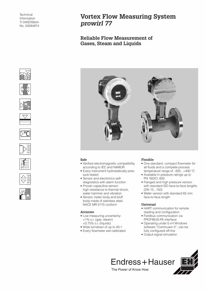
Safe• Verified electromagnetic compatibility
according to IEC and NAMUR• Every instrument hydrostatically pres-
sure tested• Sensor and electronics self-
diagnostics with alarm function• Proven capacitive sensor:
high resistance to thermal shock,water hammer and vibration
• Sensor, meter body and bluffbody made of stainless steel,NACE MR 0175 conform
Accurate• Low measuring uncertainty:
<1% o.r. (gas, steam)<0.75% o.r. (liquids)
• Wide turndown of up to 40:1• Every flowmeter wet calibrated
Flexible• One standard, compact flowmeter for
all fluids and a complete processtemperature range of –200...+400 °C
• Available in pressure ratings up toPN 160/Cl. 600
• Flanged and high pressure versionwith standard ISO face-to-face lengths(DN 15...150)
• Wafer version with standard 65 mmface-to-face length
Universal• HART communication for remote
reading and configuration• Fieldbus communication via
PROFIBUS-PA interface• Operating under E+H Windows
software “Commuwin II”, can befully configured off-line
• Output signal simulation
Vortex Flow Measuring Systemprowirl 77
Reliable Flow Measurement ofGases, Steam and Liquids
Hauser+EndressThe Power of Know How
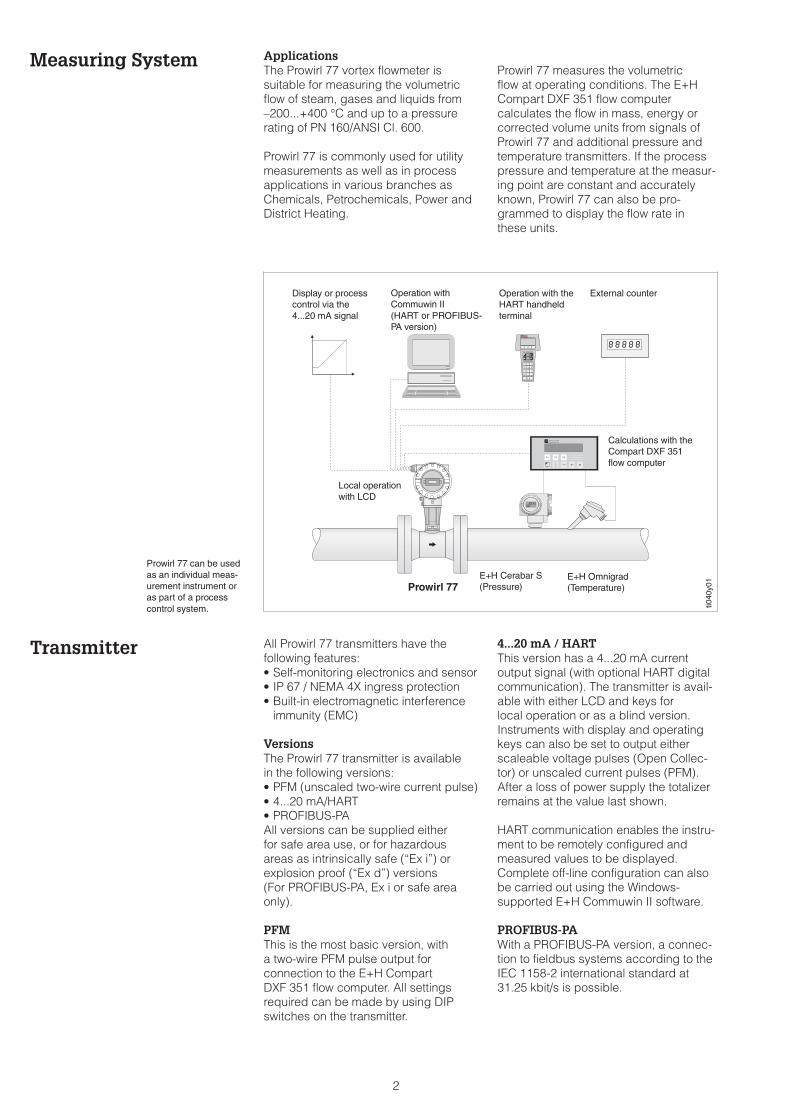
Measuring System ApplicationsThe Prowirl 77 vortex flowmeter issuitable for measuring the volumetricflow of steam, gases and liquids from–200...+400 °C and up to a pressurerating of PN 160/ANSI Cl. 600.
Prowirl 77 is commonly used for utilitymeasurements as well as in processapplications in various branches asChemicals, Petrochemicals, Power andDistrict Heating.
Prowirl 77 measures the volumetricflow at operating conditions. The E+HCompart DXF 351 flow computercalculates the flow in mass, energy orcorrected volume units from signals ofProwirl 77 and additional pressure andtemperature transmitters. If the processpressure and temperature at the measur-ing point are constant and accuratelyknown, Prowirl 77 can also be pro-grammed to display the flow rate inthese units.
Transmitter All Prowirl 77 transmitters have thefollowing features:• Self-monitoring electronics and sensor• IP 67 / NEMA 4X ingress protection• Built-in electromagnetic interference
immunity (EMC)
VersionsThe Prowirl 77 transmitter is availablein the following versions:• PFM (unscaled two-wire current pulse)• 4...20 mA/HART• PROFIBUS-PAAll versions can be supplied eitherfor safe area use, or for hazardousareas as intrinsically safe (“Ex i”) orexplosion proof (“Ex d”) versions(For PROFIBUS-PA, Ex i or safe areaonly).
PFMThis is the most basic version, witha two-wire PFM pulse output forconnection to the E+H CompartDXF 351 flow computer. All settingsrequired can be made by using DIPswitches on the transmitter.
4...20 mA / HARTThis version has a 4...20 mA currentoutput signal (with optional HART digitalcommunication). The transmitter is avail-able with either LCD and keys forlocal operation or as a blind version.Instruments with display and operatingkeys can also be set to output eitherscaleable voltage pulses (Open Collec-tor) or unscaled current pulses (PFM).After a loss of power supply the totalizerremains at the value last shown.
HART communication enables the instru-ment to be remotely configured andmeasured values to be displayed.Complete off-line configuration can alsobe carried out using the Windows-supported E+H Commuwin II software.
PROFIBUS-PAWith a PROFIBUS-PA version, a connec-tion to fieldbus systems according to theIEC 1158-2 international standard at31.25 kbit/s is possible.
ti040
y01
Operation withCommuwin II(HART or PROFIBUS-PA version)
Operation with theHART handheldterminal
Calculations with theCompart DXF 351flow computer
Local operationwith LCD
External counterDisplay or processcontrol via the4...20 mA signal
E+H Cerabar S(Pressure)
E+H Omnigrad(Temperature)Prowirl 77
Prowirl 77 can be usedas an individual meas-urement instrument oras part of a processcontrol system.
2
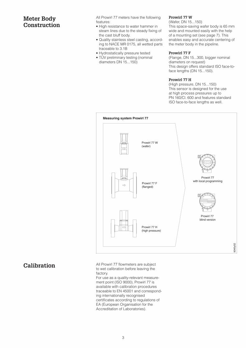
Meter BodyConstruction
All Prowirl 77 meters have the followingfeatures:• High resistance to water hammer in
steam lines due to the steady fixing ofthe cast bluff body.
• Quality stainless steel casting, accord-ing to NACE MR 0175, all wetted partstraceable to 3.1B
• Hydrostatically pressure tested• TÜV preliminary testing (nominal
diameters DN 15...150)
Prowirl 77 W(Wafer, DN 15...150)This space-saving wafer body is 65 mmwide and mounted easily with the helpof a mounting set (see page 7). Thisenables easy and accurate centering ofthe meter body in the pipeline.
Prowirl 77 F(Flange, DN 15...300, bigger nominaldiameters on request)This design offers standard ISO face-to-face lengths (DN 15...150).
Prowirl 77 H(High pressure, DN 15...150)This sensor is designed for the useat high process pressures up toPN 160/Cl. 600 and features standardISO face-to-face lengths as well.
Calibration All Prowirl 77 flowmeters are subjectto wet calibration before leaving thefactory.For use as a quality-relevant measure-ment point (ISO 9000), Prowirl 77 isavailable with calibration procedurestraceable to EN 45001 and correspond-ing internationally recognisedcertificates according to regulations ofEA (European Organisation for theAccreditation of Laboratories).
Prowirl 77 W(wafer)
Prowirl 77 F(flanged)
Prowirl 77with local programming
Prowirl 77blind version
ti040
y02
Prowirl 77 H(high pressure)
Measuring system Prowirl 77
3
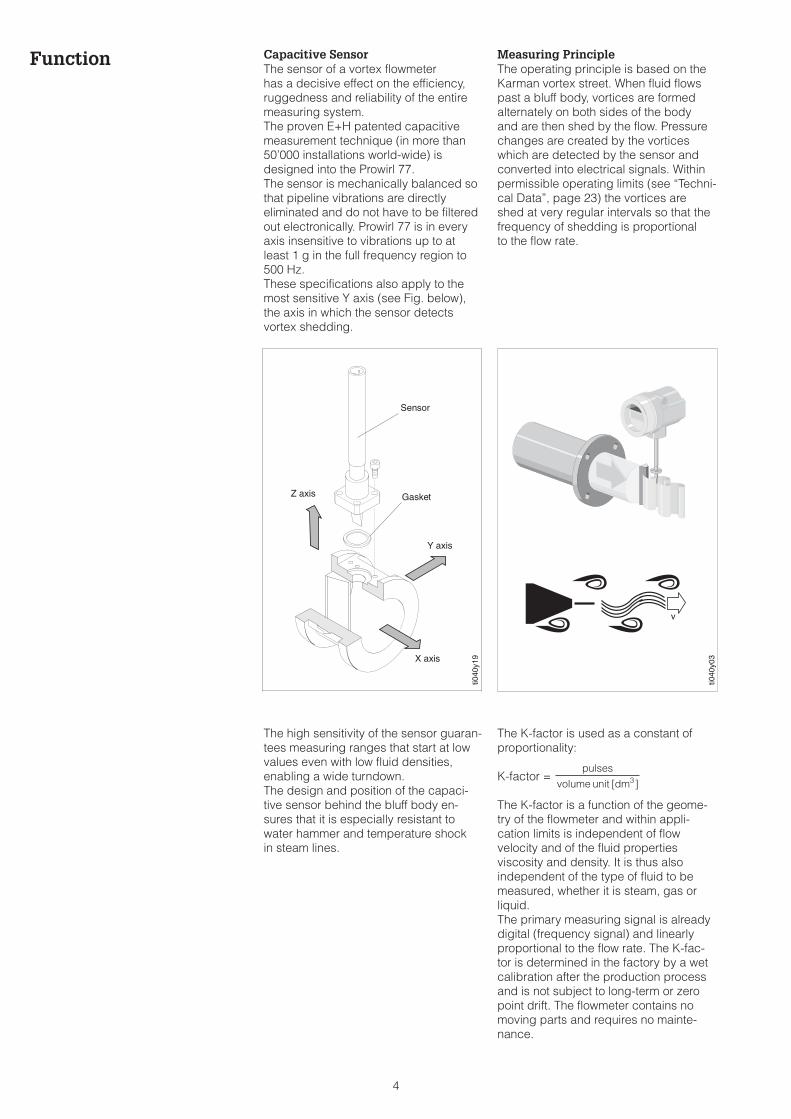
Function Capacitive SensorThe sensor of a vortex flowmeterhas a decisive effect on the efficiency,ruggedness and reliability of the entiremeasuring system.The proven E+H patented capacitivemeasurement technique (in more than50’000 installations world-wide) isdesigned into the Prowirl 77.The sensor is mechanically balanced sothat pipeline vibrations are directlyeliminated and do not have to be filteredout electronically. Prowirl 77 is in everyaxis insensitive to vibrations up to atleast 1 g in the full frequency region to500 Hz.These specifications also apply to themost sensitive Y axis (see Fig. below),the axis in which the sensor detectsvortex shedding.
The high sensitivity of the sensor guaran-tees measuring ranges that start at lowvalues even with low fluid densities,enabling a wide turndown.The design and position of the capaci-tive sensor behind the bluff body en-sures that it is especially resistant towater hammer and temperature shockin steam lines.
Measuring PrincipleThe operating principle is based on theKarman vortex street. When fluid flowspast a bluff body, vortices are formedalternately on both sides of the bodyand are then shed by the flow. Pressurechanges are created by the vorticeswhich are detected by the sensor andconverted into electrical signals. Withinpermissible operating limits (see “Techni-cal Data”, page 23) the vortices areshed at very regular intervals so that thefrequency of shedding is proportionalto the flow rate.
The K-factor is used as a constant ofproportionality:
K-factor =
The K-factor is a function of the geome-try of the flowmeter and within appli-cation limits is independent of flowvelocity and of the fluid propertiesviscosity and density. It is thus alsoindependent of the type of fluid to bemeasured, whether it is steam, gas orliquid.The primary measuring signal is alreadydigital (frequency signal) and linearlyproportional to the flow rate. The K-fac-tor is determined in the factory by a wetcalibration after the production processand is not subject to long-term or zeropoint drift. The flowmeter contains nomoving parts and requires no mainte-nance.
pulses
volume unit dm[ ]3
ti040
y03
ti040
y19
Y axis
Z axis
X axis
Sensor
Gasket
4
Planning andInstallation
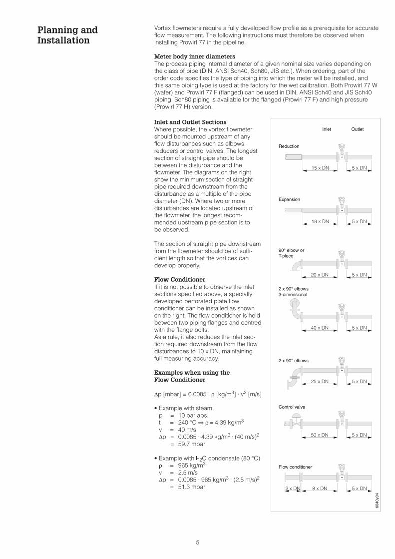
Inlet and Outlet SectionsWhere possible, the vortex flowmetershould be mounted upstream of anyflow disturbances such as elbows,reducers or control valves. The longestsection of straight pipe should bebetween the disturbance and theflowmeter. The diagrams on the rightshow the minimum section of straightpipe required downstream from thedisturbance as a multiple of the pipediameter (DN). Where two or moredisturbances are located upstream ofthe flowmeter, the longest recom-mended upstream pipe section is tobe observed.
The section of straight pipe downstreamfrom the flowmeter should be of suffi-cient length so that the vortices candevelop properly.
Flow ConditionerIf it is not possible to observe the inletsections specified above, a speciallydeveloped perforated plate flowconditioner can be installed as shownon the right. The flow conditioner is heldbetween two piping flanges and centredwith the flange bolts.As a rule, it also reduces the inlet sec-tion required downstream from the flowdisturbances to 10 x DN, maintainingfull measuring accuracy.
Examples when using theFlow Conditioner
∆p [mbar] = 0.0085 · ρ [kg/m3] · v2 [m/s]
• Example with steam:p = 10 bar abs.t = 240 °C ⇒ ρ = 4.39 kg/m3
v = 40 m/s∆p = 0.0085 · 4.39 kg/m3 · (40 m/s)2
= 59.7 mbar
• Example with H2O condensate (80 °C)ρ = 965 kg/m3
v = 2.5 m/s∆p = 0.0085 · 965 kg/m3 · (2.5 m/s)2
= 51.3 mbar
ti040
y04
Inlet Outlet
Reduction
Expansion
90° elbow orT-piece
2 x 90° elbows
2 x 90° elbows3-dimensional
Flow conditioner
Control valve
Vortex flowmeters require a fully developed flow profile as a prerequisite for accurateflow measurement. The following instructions must therefore be observed wheninstalling Prowirl 77 in the pipeline.
Meter body inner diametersThe process piping internal diameter of a given nominal size varies depending onthe class of pipe (DIN, ANSI Sch40, Sch80, JIS etc.). When ordering, part of theorder code specifies the type of piping into which the meter will be installed, andthis same piping type is used at the factory for the wet calibration. Both Prowirl 77 W(wafer) and Prowirl 77 F (flanged) can be used in DIN, ANSI Sch40 and JIS Sch40piping. Sch80 piping is available for the flanged (Prowirl 77 F) and high pressure(Prowirl 77 H) version.
5
Planning andInstallation
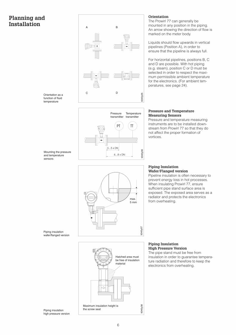
OrientationThe Prowirl 77 can generally bemounted in any position in the piping.An arrow showing the direction of flow ismarked on the meter body.
Liquids should flow upwards in verticalpipelines (Position A), in order toensure that the pipeline is always full.
For horizontal pipelines, positions B, Cand D are possible. With hot piping(e.g. steam), position C or D must beselected in order to respect the maxi-mum permissible ambient temperaturefor the electronics. (For ambient tem-peratures, see page 24).
Pressure and TemperatureMeasuring SensorsPressure and temperature measuringinstruments are to be installed down-stream from Prowirl 77 so that they donot affect the proper formation ofvortices.
Piping InsulationWafer/Flanged versionPipeline insulation is often necessary toprevent energy loss in hot processes.When insulating Prowirl 77, ensuresufficient pipe stand surface area isexposed. The exposed area serves as aradiator and protects the electronicsfrom overheating.
Piping InsulationHigh Pressure VersionThe pipe stand must be free frominsulation in order to guarantee tempera-ture radiation and therefore to keep theelectronics from overheating.
ti040
y05
A B
C DOrientation as afunction of fluidtemperature
ti040
y06
Pressuretransmitter
Temperaturetransmitter
Mounting the pressureand temperaturesensors
ti040
y07
max.5 mm
Piping insulationwafer/flanged version
ti040
y38Maximum insulation height is
the screw seat
Hatched area mustbe free of insulationmaterial
Piping insulationhigh pressure version
6
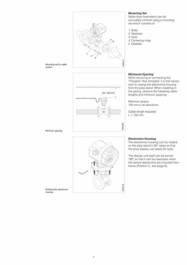
Mounting SetWafer-style flowmeters can beaccurately centred using a mountingset which consists of:
1 Bolts2 Washers3 Nuts4 Centering rings5 Gaskets
Minimum SpacingWhen servicing or connecting the“Flowjack” flow simulator, it is first neces-sary to unplug the electronics housingfrom the pipe stand. When installing inthe piping, observe the following cablelengths and minimum spacing:
Minimum space:100 mm in all directions
Cable length required:L + 150 mm
Electronics HousingThe electronics housing can be rotatedon the pipe stand in 90° steps so thatthe local display can easily be read.
The display unit itself can be turned180° so that it can be read even whenthe sensor electronics are mounted frombelow (Position C, see page 6).
ti040
y18
Rotating the electronicshousing
ti040
y08
min. 100 mm
Minimum spacing
ti040
y17
45
12
3
Mounting set for waferversion
7

Measuring RangesNominal Diameters
Selecting the Nominal DiameterThe Prowirl 77 vortex flowmeter deter-mines the volumetric flow (e.g. m3/h)under operating conditions. Steamquantities are generally given in kg or t,gas quantities in Nm3 (corrected tostandard conditions of 0 °C and1.013 bar).For conversion to operating volume anddetermining the nominal diameter,measuring range and pressure loss thefollowing tables give a first overview.
Note!If the flowmeter is operated in the upperor lower end of the measuring range,the limits of the measuring range shouldbe determined exactly using either theequations or the E+H design softwareApplicator. Your E+H Sales Organisationwill be pleased to help design a measur-ing system for your particular applica-tion with reference to the characteristicsof the fluid and operating conditions.
“Applicator” sizing SoftwareAll important transmitter data is con-tained in this E+H software for the mostefficient design of the measuring sys-tem. The equations used for calculatingthe properties of steam are the latestavailable according to the IAPS (Interna-tional Association for the Properties ofSteam).The Applicator software can easily carryout the following calculations:• Converting the operating volume of
gas into a corrected volume• Converting into a mass flow of steam
(based on temperature and/orpressure)
• Calculating using viscosity• Calculating pressure loss across the
flowmeter• Simultaneously displaying calculation
examples for various nominal diame-ters
• Determining measuring ranges
Applicator is available on Internet oras CD-ROM for local PC installation.
Measuring RangesWater / Air
The following tables are given as guide-line for measuring ranges for a typicalgas (air, at 0 °C and 1.013 bar) and atypical liquid (water, at 20 °C).
In the column “K-Factor” the possiblerange for the K-Factor with respect tonominal diameter and version is given.
Prowirl 77 W (Wafer)
DN Air (at 0 °C, 1.013 bar) Water (20 °C) K-Factor
DIN/ANSI [m3/h] [m3/h] [pulses/dm3]
min./max.
DN 15 / ½" 4 35 0.19 7 245...280
DN 25 / 1" 11 160 0.41 19 48...55
DN 40 / 1½" 31 375 1.1 45 14...17
DN 50 / 2" 50 610 1.8 73 6...8
DN 80 / 3" 112 1370 4.0 164 1.9...2.4
DN 100 / 4" 191 2330 6.9 279 1.1...1.4
DN 150 / 6" 428 5210 15.4 625 0.27...0.32
Prowirl 77 F (Flange) / Prowirl 77 H (High pressure; up to DN 150 / 6")
DN Air (at 0 °C, 1.013 bar) Water (20 °C) K-Factor
DIN/ANSI [m3/h] [m3/h] [pulses/dm3]
min./max.
DN 15 / ½" 3 25 0.16 5 390...450
DN 25 / 1" 9 125 0.32 15 70...85
DN 40 / 1½" 25 310 0.91 37 18...22
DN 50 / 2" 42 510 1.5 62 8...11
DN 80 / 3" 95 1150 3.4 140 2.5...3.2
DN 100 / 4" 164 2000 5.9 240 1.1...1.4
DN 150 / 6" 373 4540 13.4 550 0.3...0.4
DN 200 / 8" 715 8710 25.7 1050 0.1266...0.1400
DN 250 / 10" 1127 13740 40.6 1650 0.0677...0.0748
DN 300 / 12" 1617 19700 58.2 2360 0.0364...0.0402
minV maxV minV maxV
minV maxV minV maxV
8
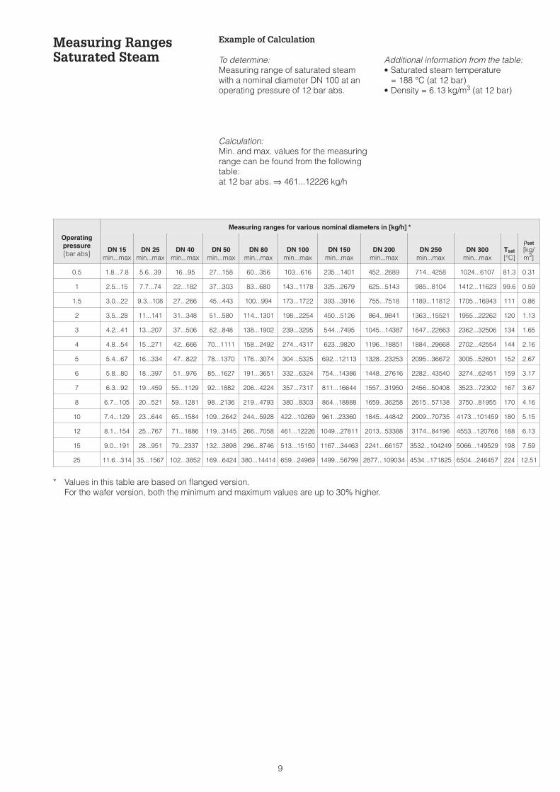
Measuring RangesSaturated Steam
Example of Calculation
To determine:Measuring range of saturated steamwith a nominal diameter DN 100 at anoperating pressure of 12 bar abs.
Calculation:Min. and max. values for the measuringrange can be found from the followingtable:at 12 bar abs. ⇒ 461...12226 kg/h
Additional information from the table:• Saturated steam temperature
= 188 °C (at 12 bar)• Density = 6.13 kg/m3 (at 12 bar)
Operatingpressure[bar abs]
Measuring ranges for various nominal diameters in [kg/h] *
DN 15min...max
DN 25min...max
DN 40min...max
DN 50min...max
DN 80min...max
DN 100min...max
DN 150min...max
DN 200min...max
DN 250min...max
DN 300min...max
Tsat
[°C]
ρsat
[kg/m3]
0.5 1.8...7.8 5.6...39 16...95 27...158 60...356 103...616 235...1401 452...2689 714...4258 1024...6107 81.3 0.31
1 2.5...15 7.7...74 22...182 37...303 83...680 143...1178 325...2679 625...5143 985...8104 1412...11623 99.6 0.59
1.5 3.0...22 9.3...108 27...266 45...443 100...994 173...1722 393...3916 755...7518 1189...11812 1705...16943 111 0.86
2 3.5...28 11...141 31...348 51...580 114...1301 198...2254 450...5126 864...9841 1363...15521 1955...22262 120 1.13
3 4.2...41 13...207 37...506 62...848 138...1902 239...3295 544...7495 1045...14387 1647...22663 2362...32506 134 1.65
4 4.8...54 15...271 42...666 70...1111 158...2492 274...4317 623...9820 1196...18851 1884...29668 2702...42554 144 2.16
5 5.4...67 16...334 47...822 78...1370 176...3074 304...5325 692...12113 1328...23253 2095...36672 3005...52601 152 2.67
6 5.8...80 18...397 51...976 85...1627 191...3651 332...6324 754...14386 1448...27616 2282...43540 3274...62451 159 3.17
7 6.3...92 19...459 55...1129 92...1882 206...4224 357...7317 811...16644 1557...31950 2456...50408 3523...72302 167 3.67
8 6.7...105 20...521 59...1281 98...2136 219...4793 380...8303 864...18888 1659...36258 2615...57138 3750...81955 170 4.16
10 7.4...129 23...644 65...1584 109...2642 244...5928 422...10269 961...23360 1845...44842 2909...70735 4173...101459 180 5.15
12 8.1...154 25...767 71...1886 119...3145 266...7058 461...12226 1049...27811 2013...53388 3174...84196 4553...120766 188 6.13
15 9.0...191 28...951 79...2337 132...3898 296...8746 513...15150 1167...34463 2241...66157 3532...104249 5066...149529 198 7.59
25 11.6...314 35...1567 102...3852 169...6424 380...14414 659...24969 1499...56799 2877...109034 4534...171825 6504...246457 224 12.51
* Values in this table are based on flanged version.For the wafer version, both the minimum and maximum values are up to 30% higher.
9
Measuring RangesSuperheated Steam
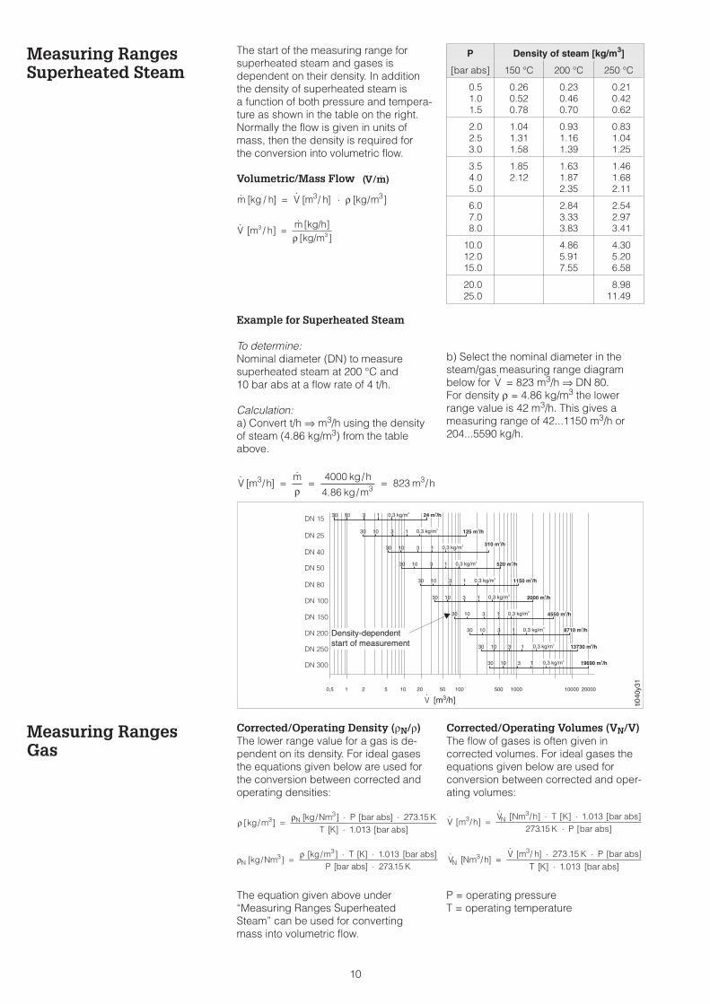
The start of the measuring range forsuperheated steam and gases isdependent on their density. In additionthe density of superheated steam isa function of both pressure and tempera-ture as shown in the table on the right.Normally the flow is given in units ofmass, then the density is required forthe conversion into volumetric flow.
Volumetric/Mass Flow
Example for Superheated Steam
To determine:Nominal diameter (DN) to measuresuperheated steam at 200 °C and10 bar abs at a flow rate of 4 t/h.
Calculation:a) Convert t/h ⇒ m3/h using the densityof steam (4.86 kg/m3) from the tableabove.
b) Select the nominal diameter in thesteam/gas measuring range diagrambelow for = 823 m3/h ⇒ DN 80.For density ρ = 4.86 kg/m3 the lowerrange value is 42 m3/h. This gives ameasuring range of 42...1150 m3/h or204...5590 kg/h.
Measuring RangesGas
Corrected/Operating Density (ρN/ρ)The lower range value for a gas is de-pendent on its density. For ideal gasesthe equations given below are used forthe conversion between corrected andoperating densities:
The equation given above under“Measuring Ranges SuperheatedSteam” can be used for convertingmass into volumetric flow.
Corrected/Operating Volumes (VN/V)The flow of gases is often given incorrected volumes. For ideal gases theequations given below are used forconversion between corrected and oper-ating volumes:
P = operating pressureT = operating temperature
(V/m)⋅
[ / ] [ / ] [ / ]m kg h V m h kg m= ⋅3 3ρ
V [m / h] =m [kg/h][kg/m ]
33ρ
V
P Density of steam [kg/m3]
[bar abs] 150 °C 200 °C 250 °C
0.51.01.5
0.260.520.78
0.230.460.70
0.210.420.62
2.02.53.0
1.041.311.58
0.931.161.39
0.831.041.25
3.54.05.0
1.852.12
1.631.872.35
1.461.682.11
6.07.08.0
2.843.333.83
2.542.973.41
10.012.015.0
4.865.917.55
4.305.206.58
20.025.0
8.9811.49
DN 15
DN 25
DN 40
DN 50
DN 80
DN 100
DN 150
DN 200
DN 250
DN 300
1 2 5 10 20 50 100 500 1000 10000 200000,5
24 m /h330 10 3 1 0,3 kg/m3
125 m /h330 10 3 1 0,3 kg/m3
310 m /h3
30 10 3 1 0,3 kg/m3
520 m /h330 10 3 1 0,3 kg/m3
1150 m /h330 10 3 1 0,3 kg/m3
2000 m /h330 10 3 1 0,3 kg/m3
4550 m /h330 10 3 1 0,3 kg/m3
8710 m /h3
19690 m /h3
30
30
30
10
10
10
3
3
3
1
1
1
0,3 kg/m3
0,3 kg/m3 13730 m /h3
0,3 kg/m3
ti040
y31
[m3/h]
Density-dependentstart of measurement
V
[ / ]/
. //V m h
m kg h
kg mm h3
334000
4 86823= = =
ρ
// .
.V [m h]
V [Nm h] T [K] [bar abs]K P [bar abs]
3 N3
= ⋅ ⋅⋅
1 01327315
[ / ][ / ] . [ ]
[ ] . [ ]V Nm h
V m h K P bar absT K bar absN
33 273 15
1 013=
⋅ ⋅⋅
ρ ρ[ / ]
[ / ] [ ] .[ ] . [ ]
kg mkg Nm P bar abs K
T K bar absN3
3 273151 013
= ⋅ ⋅⋅
ρρ
N kg Nmkg m T K bar abs
P bar abs K[ / ]
[ / ] [ ] . [ ][ ] .
33 1 013
27315=
⋅ ⋅⋅
10

Measuring RangesLiquids
Example for Liquids
To determine:Nominal diameter (DN) to measurea liquid with a density of 0.8 kg/dm3
and a kinematic viscosity of 2 cSt at aflow rate of 40 m3/h.
Calculation:Select the nominal diameter in theliquids measuring range diagrambelow for V = 40 m3/h ⇒ DN 50.For ρ = 0.8 kg/dm3 and a kinematicviscosity of 2 cSt. the lower range-valueis 1.5 m3/h and the linear measuringrange starts at 5.6 m3/h. This gives ameasuring range of 1.5...62 m3/h or1200...49600 kg/h.
Pressure Loss
Example for Saturated SteamTo determine:Pressure loss for a saturated steam flowof 8 t/h (12 bar abs.) with a nominaldiameter DN 100.
Calculation:Convert kg/h ⇒ m3/h using the densityof steam (6.13 kg/m3) from the table onpage 10.
= 1305 m3/h and DN = 100 ⇒ C = 20∆p = C·ρ = 20 · 6.13 kg/m3 ⇒ 123 mbarV
DN25
DN40
DN50
DN80
DN15
DN10
0
DN15
0DN
200
DN25
0DN
300
0,5 1 2 3 4 5 10 20 30 40 50 100 200 500 1000 2000 5000 10000 20000
0,01
0,05
0,1
0,5
1
5
10
50
100
Coe
ffici
entC
ti040
y20
in m3/hV
240 m /h3
140 m /h3
37 m /h3
15 m /h3
5 m /h3
62 m /h3
550 m /h3
1050 m /h3
1650 m /h3
2360 m /h3
11,2 0,6 kg/dm3
11,2 0,6 kg/dm3
11,2 0,6 kg/dm3
11,2 0,6 kg/dm3
11,2 0,6 kg/dm3
11,2 0,6 kg/dm3
11,2 0,6 kg/dm3
1
1
1
1,2
1,2
1,2
0,6 kg/dm3
0,6 kg/dm3
0,6 kg/dm3
0,5 1 5 10 50 100 1000 20000,1 500
32 cSt.16842
32 cSt.16842
32 cSt.1684
32 cSt.1684
16 cSt.8421
8 cSt.421
8 cSt.4
4 cSt.
4 cSt.
2
2
2
1
1
1
16 cSt.8421
0.5
0.5
0.5
0.5
0.4
0.4
0.30.20.1
0.30.2
DN 15
DN 25
DN 40
DN 50
DN 80
DN 100
DN 150
DN 200
DN 250
DN 300
ti040
y32
Kinematic viscosityindicates start oflinear measuringrange
Density-dependentstart of measurement
in m3/hV
[ / ]/
. //V m h
m kg h
kg mm h3
338000
6131305= = =
ρ
Pressure Loss:∆p [mbar] = coefficient C · density ρ [kg/m3]Determine the C coefficient from the diagram below
11
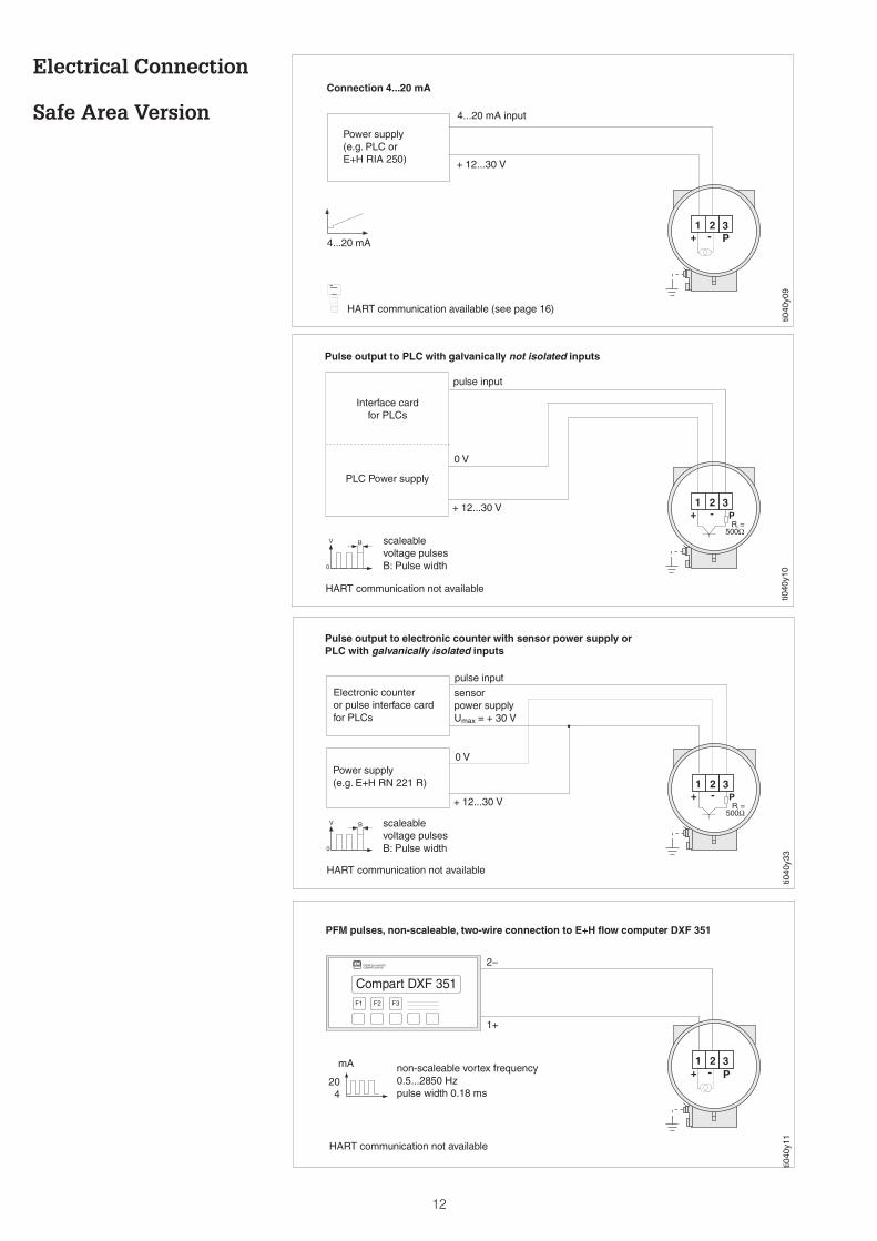
Electrical Connection
Safe Area Version
1 2 3+ - P
ti040
y09
Connection 4...20 mA
4...20 mA
Power supply(e.g. PLC orE+H RIA 250)
a HART communication available (see page 16)
4...20 mA input
+ 12...30 V
1 2 3+ - P
R =500
iΩ
V
0
B
ti040
y10
scaleablevoltage pulsesB: Pulse width
Interface cardfor PLCs
PLC Power supply
Pulse output to PLC with galvanically not isolated inputs
HART communication not available
pulse input
0 V
+ 12...30 V
1 2 3+ - P
R =500
iΩ
V
0
B
ti040
y33
Power supply(e.g. E+H RN 221 R)
Pulse output to electronic counter with sensor power supply orPLC with galvanically isolated inputs
Electronic counteror pulse interface cardfor PLCs
HART communication not available
scaleablevoltage pulsesB: Pulse width
pulse input
sensorpower supplyUmax = + 30 V
0 V
+ 12...30 V
Compart DXF 351
ENDRESS+HAUSERCOMPARTDXF351
F1 F3F2
1 2 3+ - P
ti040
y11
non-scaleable vortex frequency0.5...2850 Hzpulse width 0.18 ms
PFM pulses, non-scaleable, two-wire connection to E+H flow computer DXF 351
HART communication not available
mA
204
2–
1+
12
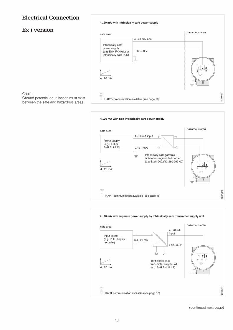
Electrical Connection
Ex i version
1 2 3+ - P
4...20 mA with intrinsically safe power supply
ti040
y22
Intrinsically safepower supply:(e.g. E+H FXN 672 orintrinsically safe PLC)
4...20 mA
safe areahazardous area
a HART communication available (see page 16)
4...20 mA input
+ 12...30 V
1 2 3+ - P
(-)
(+)
(-)
(+)
hazardous areasafe area
4...20 mA with non-intrinsically safe power supply
Intrinsically safe galvanicisolator or ungrounded barrier(e.g. Stahl 9002/13-280-093-00)
4...20 mA
ti040
y23
Power supply:(e.g. PLC orE+H RIA 250)
a HART communication available (see page 16)
4...20 mA input
+ 12...30 V
1 2 3+ - P
4...20 mA
Intrinsically safetransmitter supply unit(e.g. E+H RN 221 Z)
4...20 mA with separate power supply by intrinsically safe transmitter supply unit
hazardous areasafe area
ti040
y34
Input board:(e.g. PLC, display,recorder)
a HART communication available (see page 16)
4...20 mAinput
+ 12...30 V+ +
– –
L+ L–
0/4...20 mA
Caution!Ground potential equalisation must existbetween the safe and hazardous areas.
(continued next page)
13
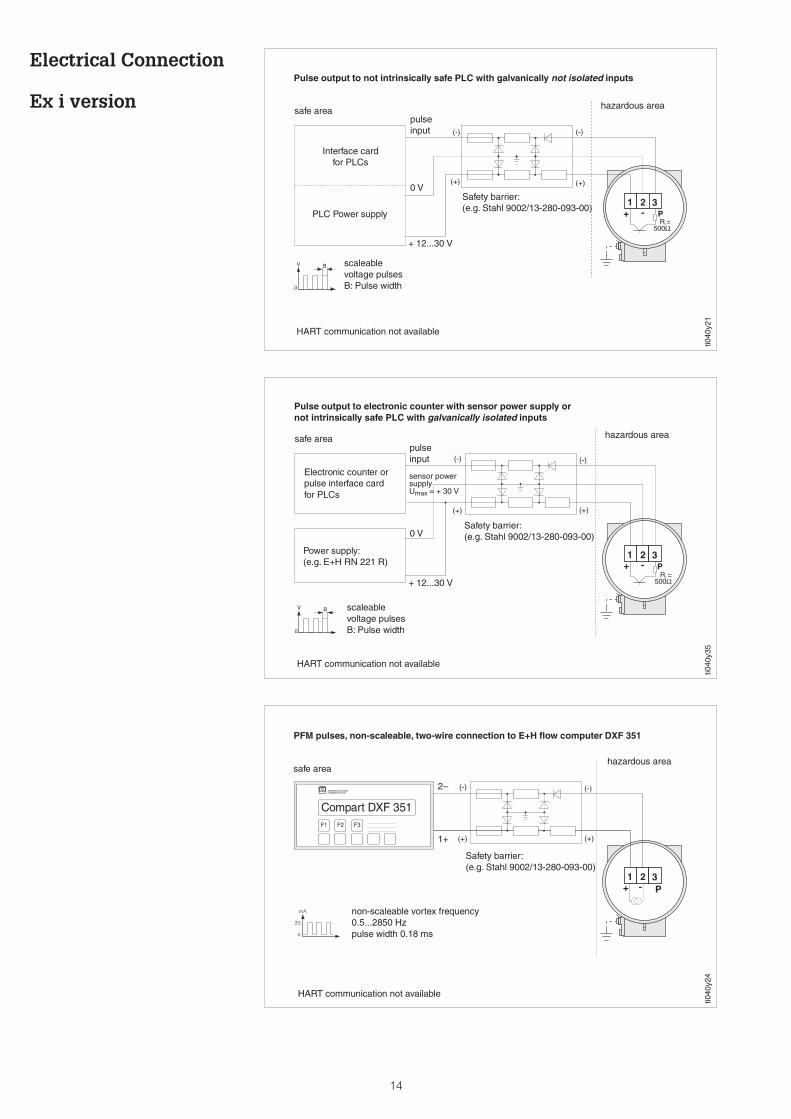
Electrical Connection
Ex i version
1 2 3+ - P
(+)
(-)
(+)
(-)
R =500
iΩ
V
0
B
Pulse output to electronic counter with sensor power supply ornot intrinsically safe PLC with galvanically isolated inputs
ti040
y35
HART communication not available
safe area hazardous area
Electronic counter orpulse interface cardfor PLCs
Power supply:(e.g. E+H RN 221 R)
Safety barrier:(e.g. Stahl 9002/13-280-093-00)
pulseinput
sensor powersupplyUmax = + 30 V
0 V
+ 12...30 V
scaleablevoltage pulsesB: Pulse width
1 2 3+ - P
Compart DXF 351
ENDRESS+HAUSERCOMPARTDXF351
F1 F3F2
(+)
(-)
(+)
(-)
mA
20
4
PFM pulses, non-scaleable, two-wire connection to E+H flow computer DXF 351
ti040
y24
non-scaleable vortex frequency0.5...2850 Hzpulse width 0.18 ms
HART communication not available
safe areahazardous area
Safety barrier:(e.g. Stahl 9002/13-280-093-00)
2–
1+
1 2 3+ - P
(-)
(+)
(-)
(+)
R =500
iΩ
V
0
B
hazardous areasafe area
Pulse output to not intrinsically safe PLC with galvanically not isolated inputs
Safety barrier:(e.g. Stahl 9002/13-280-093-00)
Interface cardfor PLCs
PLC Power supply
HART communication not available
ti040
y21
pulseinput
0 V
+ 12...30 V
scaleablevoltage pulsesB: Pulse width
14
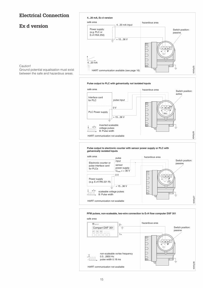
Electrical Connection
Ex d version
1 2 3+ - P
ti040
y25
4...20 mA, Ex d version
Power supply:(e.g. PLC orE+H RIA 250)
4...20 mA
hazardous areasafe area
Switch position:passive
Caution!Ground potential equalisation must existbetween the safe and hazardous areas.
a HART communication available (see page 16)
4...20 mA input
+ 15...36 V
1 2 3+ - P
38kΩ
V
0
B
ti040
y26
Interface cardfor PLC
PLC Power supply
Pulse output to PLC with galvanically not isolated inputs
hazardous areasafe areaSwitch position:active
HART communication not available
Inverted scaleablevoltage pulsesB: Pulse width
pulse input
0 V
+ 15...36 V
1 2 3+ - P
Compart DXF 351
ENDRESS+HAUSERCOMPARTDXF351
F1 F3F2
mA
20
4
ti040
y36
hazardous area
safe area
PFM pulses, non-scaleable, two-wire connection to E+H flow computer DXF 351
Switch position:passive
non-scaleable vortex frequency0.5...2850 Hzpulse width 0.18 ms
HART communication not available
2–
1+
1 2 3+ - P
R =200
iΩ
V
0
B
ti040
y27
Pulse output to electronic counter with sensor power supply or PLC withgalvanically isolated inputs
Power supply(e.g. E+H RN 221 R)
hazardous areasafe area
Electronic counter orpulse interface cardfor PLCs
Switch position:passive
HART communication not available
pulseinput
sensorpower supplyUmax = + 36 V
0 V
+ 15...36 V
scaleable voltage pulsesB: Pulse width
15
IO
FMR1130:LIC0001Online1 >Group Select2 PV 8.7 m
HELP
IO
FMR1130:LIC0001Online1 > Matrix group sel.2 PV 8.7 m3/h3 Tot4 AO15 VFHELP
IO
FMR1130:LIC0001Online1 >Group Select2 PV 8.7 m
HELP
IO
IO
FMR1130:LIC0001Online1 >Group Select2 PV 8.7 m
HELP
IO
1 2 3+ -
+
-
P
ti040
y12
min. 250 Ω
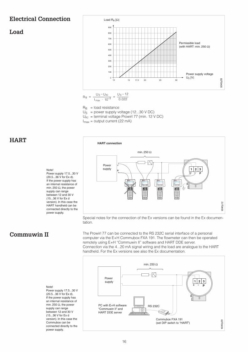
HART connection
PowersupplyNote!
Power supply 17.5...30 V(20.5...36 V for Ex d).If the power supply hasan internal resistance ofmin. 250 Ω, the powersupply can rangebetween 12 and 30 V(15...36 V for Ex dversion). In this case theHART handheld can beconnected directly to thepower supply.
Load RB [Ω]
Permissible load(with HART: min. 250 Ω)
Power supply voltageUS [V]
ti040
y28
The Prowirl 77 can be connected to the RS 232C serial interface of a personalcomputer via the E+H Commubox FXA 191. The flowmeter can then be operatedremotely using E+H “Commuwin II” software and HART DDE server.Connection via the 4...20 mA signal wiring and the load are analogue to the HARThandheld. For the Ex versions see also the Ex documentation.
RB = load resistanceUS = power supply voltage (12...30 V DC)UKI = terminal voltage Prowirl 77 (min. 12 V DC)Imax = output current (22 mA)
BS KI S
RU U
I
U=
−⋅
=−
−max .310
12
0 022
1 2 3+ - P
min. 250 Ω
PC with E+H software“Commuwin II” andHART DDE server
ti040
y29
RS 232C
Powersupply
Commubox FXA 191(set DIP switch to “HART”)
Note!Power supply 17.5...30 V(20.5...36 V for Ex d).If the power supply hasan internal resistance ofmin. 250 Ω, the powersupply can rangebetween 12 and 30 V(15...36 V for Ex dversion). In this case theCommubox can beconnected directly to thepower supply.
HART
Commuwin II
Special notes for the connection of the Ex versions can be found in the Ex documen-tation.
Electrical Connection
Load
16
Dimensions andWeights
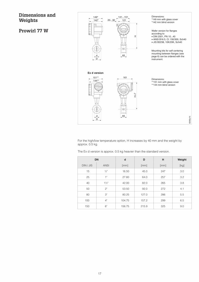
Prowirl 77 W
DN d D H Weight
DIN / JIS ANSI [mm] [mm] [mm] [kg]
15 ½" 16.50 45.0 247 3.0
25 1" 27.60 64.0 257 3.2
40 1½" 42.00 82.0 265 3.8
50 2" 53.50 92.0 272 4.1
80 3" 80.25 127.0 286 5.5
100 4" 104.75 157.2 299 6.5
150 6" 156.75 215.9 325 9.0
Dimensions:*149 mm with glass cover*142 mm blind version
Wafer version for flangesaccording to:• DIN 2501, PN 10...40• ANSI B16.5, Cl. 150/300, Sch40• JIS B2238, 10K/20K, Sch40
Mounting kits for self centeringmounting between flanges (seepage 6) can be ordered with theinstrument.
Dimensions:**151 mm with glass cover**144 mm blind version
ti040
y14
Ex d version
For the high/low temperature option, H increases by 40 mm and the weight byapprox. 0.5 kg.
The Ex d version is approx. 0.5 kg heavier than the standard version.
17
Dimensions andWeights
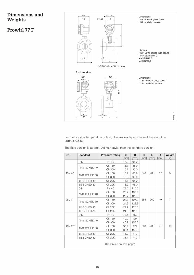
Prowirl 77 F
Dimensions:*149 mm with glass cover*142 mm blind version
Flanges:• DIN 2501, raised face acc. to• DIN 2526 form C• ANSI B16.5• JIS B2238
Dimensions:**151 mm with glass cover**144 mm blind version
(ISO/DVGW for DN 15...150)
Ex d version
ti040
y13
DN Standard Pressure rating d[mm]
D[mm]
H[mm]
L[mm]
X[mm]
Weight[kg]
15 / ½"
DIN PN 40 17.3 95.0
248 200 17 5
ANSI SCHED 40Cl. 150 15.7 88.9Cl. 300 15.7 95.0
ANSI SCHED 80Cl. 150 13.9 88.9Cl. 300 13.9 95.0
JIS SCHED 40 Cl. 20K 16.1 95.0JIS SCHED 80 Cl. 20K 13.9 95.0
25 / 1"
DIN PN 40 28.5 115.0
255 200 19 7
ANSI SCHED 40Cl. 150 26.7 107.9Cl. 300 26.7 123.8
ANSI SCHED 80Cl. 150 24.3 107.9Cl. 300 24.3 123.8
JIS SCHED 40 Cl. 20K 27.2 125.0JIS SCHED 80 Cl. 20K 24.3 125.0
40 / 1½"
DIN PN 40 43.1 150
263 200 21 10
ANSI SCHED 40Cl. 150 40.9 127Cl. 300 40.9 155.6
ANSI SCHED 80Cl. 150 38.1 127Cl. 300 38.1 155.6
JIS SCHED 40 Cl. 20K 41.2 140JIS SCHED 80 Cl. 20K 38.1 140
(Continued on next page)
For the high/low temperature option, H increases by 40 mm and the weight byapprox. 0.5 kg.
The Ex d version is approx. 0.5 kg heavier than the standard version.
18
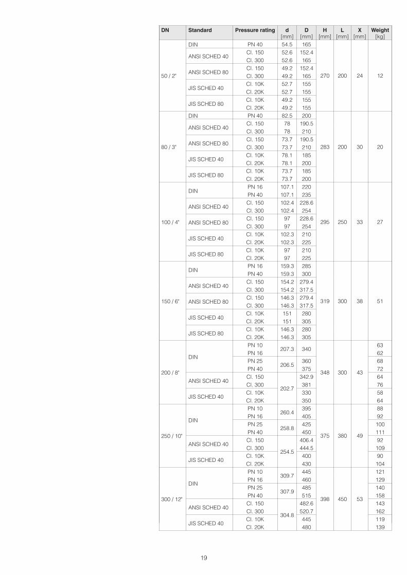
DN Standard Pressure rating d[mm]
D[mm]
H[mm]
L[mm]
X[mm]
Weight[kg]
50 / 2"
DIN PN 40 54.5 165
270 200 24 12
ANSI SCHED 40Cl. 150 52.6 152.4Cl. 300 52.6 165
ANSI SCHED 80Cl. 150 49.2 152.4Cl. 300 49.2 165
JIS SCHED 40Cl. 10K 52.7 155Cl. 20K 52.7 155
JIS SCHED 80Cl. 10K 49.2 155Cl. 20K 49.2 155
80 / 3"
DIN PN 40 82.5 200
283 200 30 20
ANSI SCHED 40Cl. 150 78 190.5Cl. 300 78 210
ANSI SCHED 80Cl. 150 73.7 190.5Cl. 300 73.7 210
JIS SCHED 40Cl. 10K 78.1 185Cl. 20K 78.1 200
JIS SCHED 80Cl. 10K 73.7 185Cl. 20K 73.7 200
100 / 4"
DINPN 16 107.1 220
295 250 33 27
PN 40 107.1 235
ANSI SCHED 40Cl. 150 102.4 228.6Cl. 300 102.4 254
ANSI SCHED 80Cl. 150 97 228.6Cl. 300 97 254
JIS SCHED 40Cl. 10K 102.3 210Cl. 20K 102.3 225
JIS SCHED 80Cl. 10K 97 210Cl. 20K 97 225
150 / 6"
DINPN 16 159.3 285
319 300 38 51
PN 40 159.3 300
ANSI SCHED 40Cl. 150 154.2 279.4Cl. 300 154.2 317.5
ANSI SCHED 80Cl. 150 146.3 279.4Cl. 300 146.3 317.5
JIS SCHED 40Cl. 10K 151 280Cl. 20K 151 305
JIS SCHED 80Cl. 10K 146.3 280Cl. 20K 146.3 305
200 / 8"
DIN
PN 10207.3 340
348 300 43
63PN 16 62PN 25
206.5360 68
PN 40 375 72
ANSI SCHED 40Cl. 150
202.7
342.9 64Cl. 300 381 76
JIS SCHED 40Cl. 10K 330 58Cl. 20K 350 64
250 / 10"
DIN
PN 10260.4
395
375 380 49
88PN 16 405 92PN 25
258.8425 100
PN 40 450 111
ANSI SCHED 40Cl. 150
254.5
406.4 92Cl. 300 444.5 109
JIS SCHED 40Cl. 10K 400 90Cl. 20K 430 104
300 / 12"
DIN
PN 10309.7
445
398 450 53
121PN 16 460 129PN 25
307.9485 140
PN 40 515 158
ANSI SCHED 40Cl. 150
304.8
482.6 143Cl. 300 520.7 162
JIS SCHED 40Cl. 10K 445 119Cl. 20K 480 139
19
Dimensions andWeights
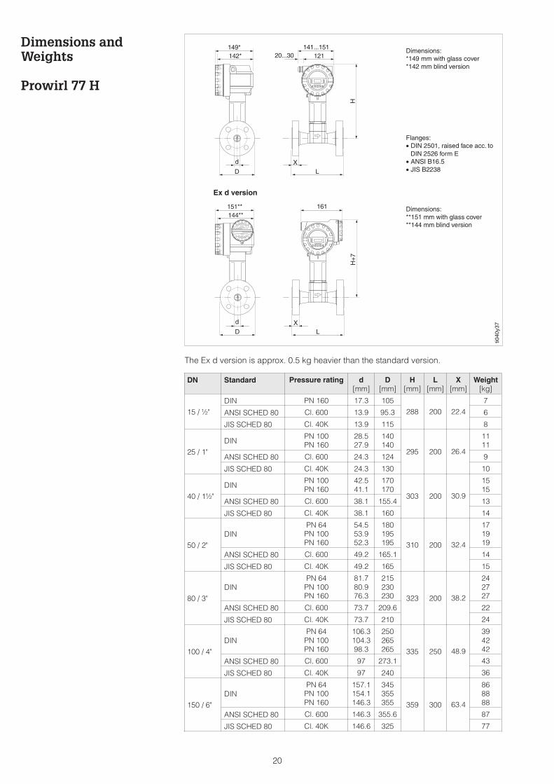
Prowirl 77 H
ti040
y37
Dimensions:*149 mm with glass cover*142 mm blind version
Flanges:• DIN 2501, raised face acc. to• DIN 2526 form E• ANSI B16.5• JIS B2238
Dimensions:**151 mm with glass cover**144 mm blind version
Ex d version
DN Standard Pressure rating d[mm]
D[mm]
H[mm]
L[mm]
X[mm]
Weight[kg]
15 / ½"
DIN PN 160 17.3 105
288 200 22.4
7
ANSI SCHED 80 Cl. 600 13.9 95.3 6
JIS SCHED 80 Cl. 40K 13.9 115 8
25 / 1"
DINPN 100PN 160
28.527.9
140140
295 200 26.4
1111
ANSI SCHED 80 Cl. 600 24.3 124 9
JIS SCHED 80 Cl. 40K 24.3 130 10
40 / 1½"
DINPN 100PN 160
42.541.1
170170
303 200 30.9
1515
ANSI SCHED 80 Cl. 600 38.1 155.4 13
JIS SCHED 80 Cl. 40K 38.1 160 14
50 / 2"
DINPN 64
PN 100PN 160
54.553.952.3
180195195 310 200 32.4
171919
ANSI SCHED 80 Cl. 600 49.2 165.1 14
JIS SCHED 80 Cl. 40K 49.2 165 15
80 / 3"
DINPN 64
PN 100PN 160
81.780.976.3
215230230 323 200 38.2
242727
ANSI SCHED 80 Cl. 600 73.7 209.6 22
JIS SCHED 80 Cl. 40K 73.7 210 24
100 / 4"
DINPN 64
PN 100PN 160
106.3104.398.3
250265265 335 250 48.9
394242
ANSI SCHED 80 Cl. 600 97 273.1 43
JIS SCHED 80 Cl. 40K 97 240 36
150 / 6"
DINPN 64
PN 100PN 160
157.1154.1146.3
345355355 359 300 63.4
868888
ANSI SCHED 80 Cl. 600 146.3 355.6 87
JIS SCHED 80 Cl. 40K 146.6 325 77
The Ex d version is approx. 0.5 kg heavier than the standard version.
20
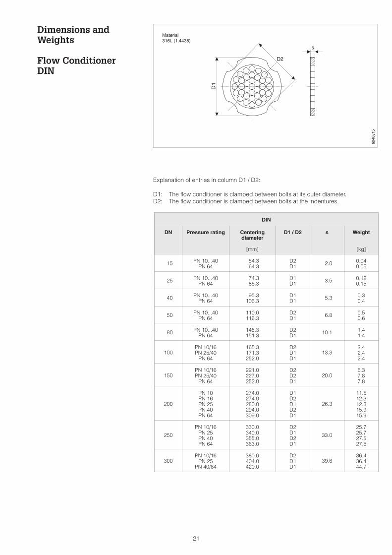
Dimensions andWeights
Flow ConditionerDIN
ti040
y15
Material316L (1.4435)
DIN
DN Pressure rating Centeringdiameter
[mm]
D1 / D2 s Weight
[kg]
15 PN 10...40PN 64
54.364.3
D2D1 2.0 0.04
0.05
25 PN 10...40PN 64
74.385.3
D1D1 3.5 0.12
0.15
40 PN 10...40PN 64
95.3106.3
D1D1 5.3 0.3
0.4
50 PN 10...40PN 64
110.0116.3
D2D1 6.8 0.5
0.6
80 PN 10...40PN 64
145.3151.3
D2D1 10.1 1.4
1.4
100PN 10/16PN 25/40
PN 64
165.3171.3252.0
D2D1D1
13.32.42.42.4
150PN 10/16PN 25/40
PN 64
221.0227.0252.0
D2D2D1
20.06.37.87.8
200
PN 10PN 16PN 25PN 40PN 64
274.0274.0280.0294.0309.0
D1D2D1D2D1
26.3
11.512.312.315.915.9
250
PN 10/16PN 25PN 40PN 64
330.0340.0355.0363.0
D2D1D2D1
33.0
25.725.727.527.5
300PN 10/16
PN 25PN 40/64
380.0404.0420.0
D2D1D1
39.636.436.444.7
Explanation of entries in column D1 / D2:
D1: The flow conditioner is clamped between bolts at its outer diameter.D2: The flow conditioner is clamped between bolts at the indentures.
21
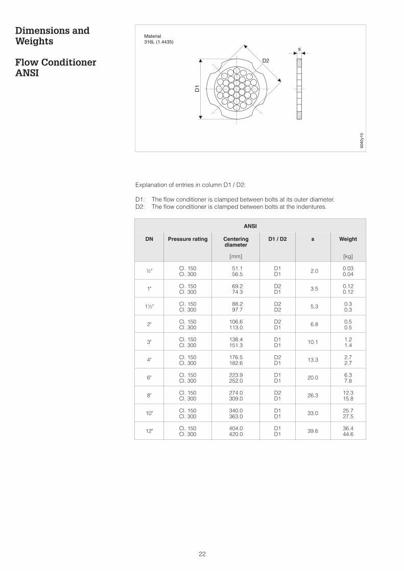
Dimensions andWeights
Flow ConditionerANSI
ANSI
DN Pressure rating Centeringdiameter
[mm]
D1 / D2 s Weight
[kg]
½" Cl. 150Cl. 300
51.156.5
D1D1 2.0 0.03
0.04
1" Cl. 150Cl. 300
69.274.3
D2D1 3.5 0.12
0.12
1½" Cl. 150Cl. 300
88.297.7
D2D2 5.3 0.3
0.3
2" Cl. 150Cl. 300
106.6113.0
D2D1 6.8 0.5
0.5
3" Cl. 150Cl. 300
138.4151.3
D1D1 10.1 1.2
1.4
4" Cl. 150Cl. 300
176.5182.6
D2D1 13.3 2.7
2.7
6" Cl. 150Cl. 300
223.9252.0
D1D1 20.0 6.3
7.8
8" Cl. 150Cl. 300
274.0309.0
D2D1 26.3 12.3
15.8
10" Cl. 150Cl. 300
340.0363.0
D1D1 33.0 25.7
27.5
12" Cl. 150Cl. 300
404.0420.0
D1D1 39.6 36.4
44.6
ti040
y15
Material316L (1.4435)
Explanation of entries in column D1 / D2:
D1: The flow conditioner is clamped between bolts at its outer diameter.D2: The flow conditioner is clamped between bolts at the indentures.
22
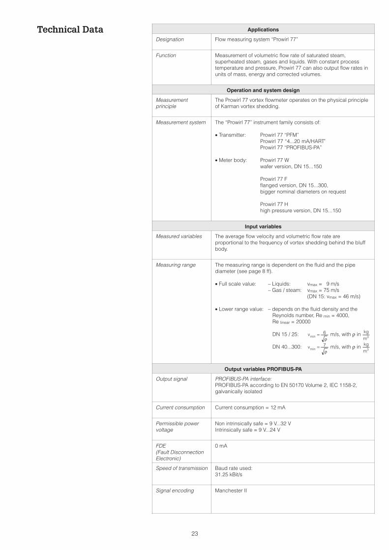
Technical Data Applications
Designation Flow measuring system “Prowirl 77”
Function Measurement of volumetric flow rate of saturated steam,superheated steam, gases and liquids. With constant processtemperature and pressure, Prowirl 77 can also output flow rates inunits of mass, energy and corrected volumes.
Operation and system design
Measurementprinciple
The Prowirl 77 vortex flowmeter operates on the physical principleof Karman vortex shedding.
Measurement system The “Prowirl 77” instrument family consists of:
• Transmitter: Prowirl 77 “PFM”Prowirl 77 “4...20 mA/HART”Prowirl 77 “PROFIBUS-PA”
• Meter body: Prowirl 77 Wwafer version, DN 15...150
Prowirl 77 Fflanged version, DN 15...300,bigger nominal diameters on request
Prowirl 77 Hhigh pressure version, DN 15...150
Input variables
Measured variables The average flow velocity and volumetric flow rate areproportional to the frequency of vortex shedding behind the bluffbody.
Measuring range The measuring range is dependent on the fluid and the pipediameter (see page 8 ff).
• Full scale value: – Liquids: vmax = 9 m/s– Gas / steam: vmax = 75 m/s
(DN 15: vmax = 46 m/s)
• Lower range value: – depends on the fluid density and theReynolds number, Re min = 4000,Re linear = 20000
DN 15 / 25: m/s, with ρ in
DN 40...300: m/s, with ρ in
Output variables PROFIBUS-PA
Output signal PROFIBUS-PA interface:PROFIBUS-PA according to EN 50170 Volume 2, IEC 1158-2,galvanically isolated
Current consumption Current consumption = 12 mA
Permissible powervoltage
Non intrinsically safe = 9 V...32 VIntrinsically safe = 9 V...24 V
FDE(Fault DisconnectionElectronic)
0 mA
Speed of transmission Baud rate used:31.25 kBit/s
Signal encoding Manchester II
vmin = 6ρ
kg
m3
vmin = 7ρ
kg
m3
23
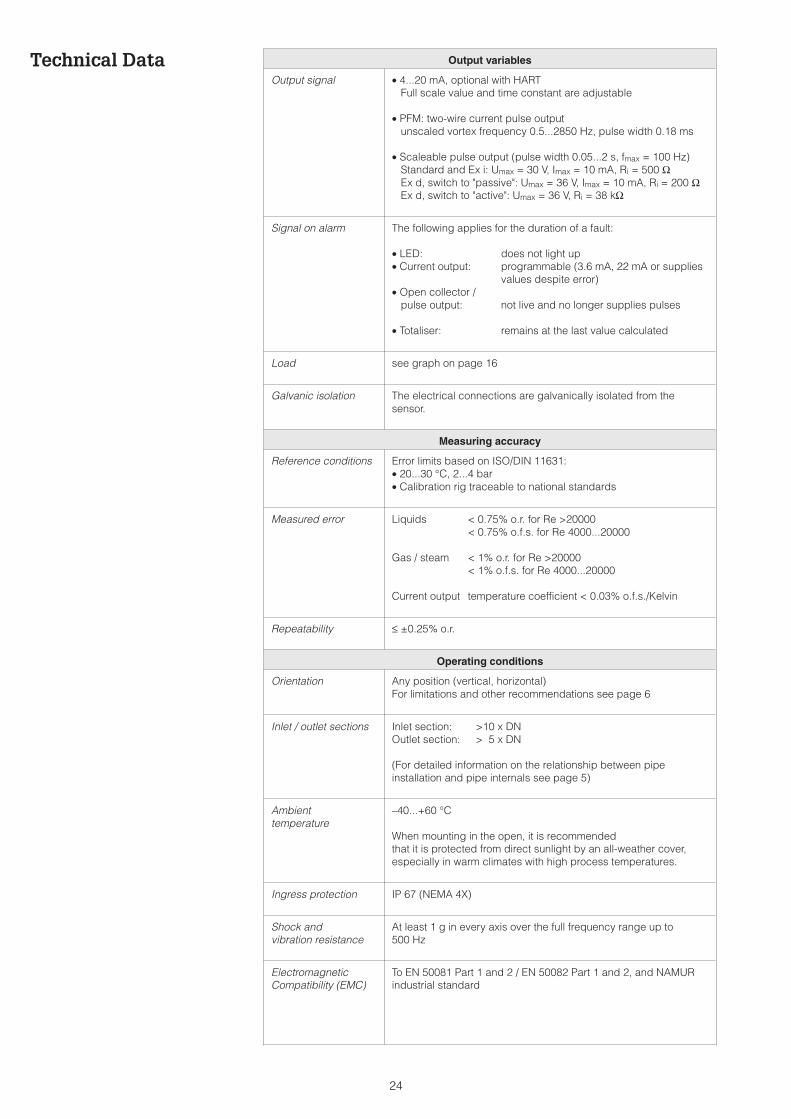
Technical Data Output variables
Output signal • 4...20 mA, optional with HARTFull scale value and time constant are adjustable
• PFM: two-wire current pulse outputunscaled vortex frequency 0.5...2850 Hz, pulse width 0.18 ms
• Scaleable pulse output (pulse width 0.05...2 s, fmax = 100 Hz)Standard and Ex i: Umax = 30 V, Imax = 10 mA, Ri = 500 ΩEx d, switch to "passive": Umax = 36 V, Imax = 10 mA, Ri = 200 ΩEx d, switch to "active": Umax = 36 V, Ri = 38 kΩ
Signal on alarm The following applies for the duration of a fault:
• LED: does not light up• Current output: programmable (3.6 mA, 22 mA or supplies
values despite error)• Open collector /
pulse output: not live and no longer supplies pulses
• Totaliser: remains at the last value calculated
Load see graph on page 16
Galvanic isolation The electrical connections are galvanically isolated from thesensor.
Measuring accuracy
Reference conditions Error limits based on ISO/DIN 11631:• 20...30 °C, 2...4 bar• Calibration rig traceable to national standards
Measured error Liquids < 0.75% o.r. for Re >20000< 0.75% o.f.s. for Re 4000...20000
Gas / steam < 1% o.r. for Re >20000< 1% o.f.s. for Re 4000...20000
Current output temperature coefficient < 0.03% o.f.s./Kelvin
Repeatability ≤ ±0.25% o.r.
Operating conditions
Orientation Any position (vertical, horizontal)For limitations and other recommendations see page 6
Inlet / outlet sections Inlet section: >10 x DNOutlet section: > 5 x DN
(For detailed information on the relationship between pipeinstallation and pipe internals see page 5)
Ambienttemperature
–40...+60 °C
When mounting in the open, it is recommendedthat it is protected from direct sunlight by an all-weather cover,especially in warm climates with high process temperatures.
Ingress protection IP 67 (NEMA 4X)
Shock andvibration resistance
At least 1 g in every axis over the full frequency range up to500 Hz
ElectromagneticCompatibility (EMC)
To EN 50081 Part 1 and 2 / EN 50082 Part 1 and 2, and NAMURindustrial standard
24
Process conditions
Process temperature • Fluid: Standard sensor –40...+260 °CHigh/low temperature sensor –200...+400 °CWafer type instruments of sizes DN 100 (4") andDN 150 (6") may not be mounted in orientationaccording to position B (see page 6) for fluidtemperatures above 200 °C.
• Seal: Graphite –200...+400 °CViton – 15...+175 °CKalrez – 20...+220 °CGylon (PTFE) –200...+260 °C
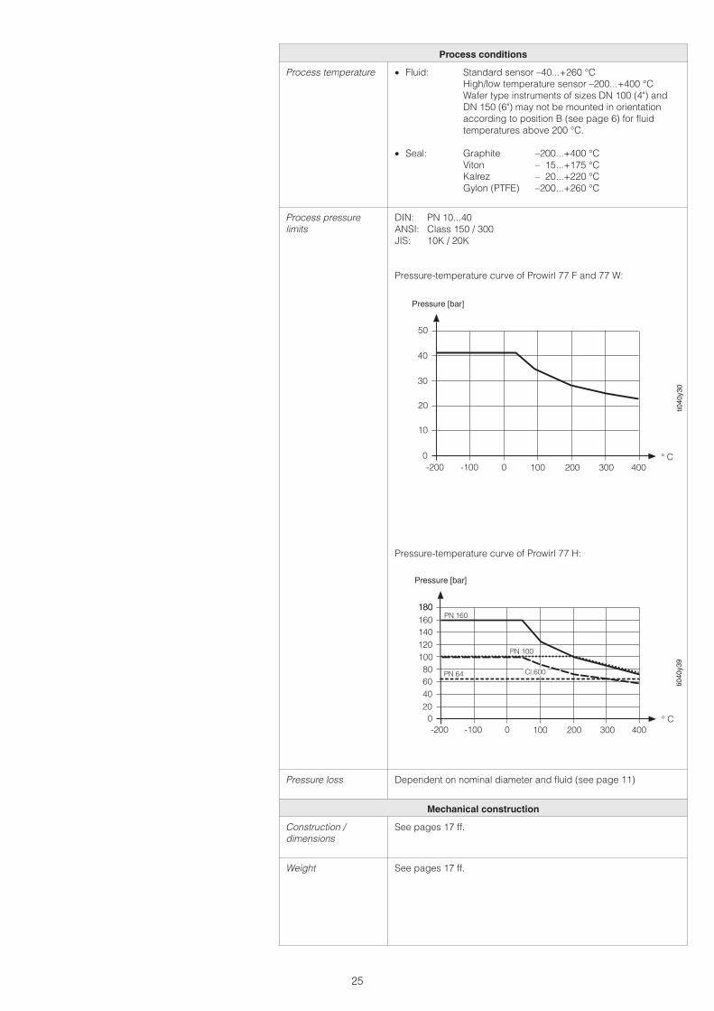
Process pressurelimits
DIN: PN 10...40ANSI: Class 150 / 300JIS: 10K / 20K
Pressure-temperature curve of Prowirl 77 F and 77 W:
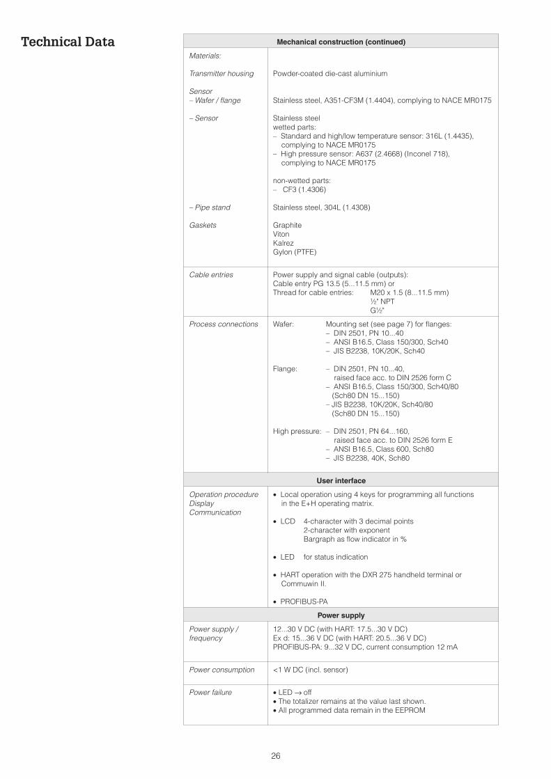
Pressure-temperature curve of Prowirl 77 H:
Pressure loss Dependent on nominal diameter and fluid (see page 11)
Mechanical construction
Construction /dimensions
See pages 17 ff.
Weight See pages 17 ff.
300 400100 2000-100-200
20
30
40
50
0
10
° C
ti040
y30
Pressure [bar]
300 400100 2000-100-200
40
80
120
160180
020
60
100
140
180PN 160
PN 100
PN 64
° C
Cl.600
Pressure [bar]
ti040
y39
25
Technical Data Mechanical construction (continued)
Materials:
Transmitter housing
Sensor– Wafer / flange
– Sensor
– Pipe stand
Gaskets
Powder-coated die-cast aluminium
Stainless steel, A351-CF3M (1.4404), complying to NACE MR0175
Stainless steelwetted parts:– Standard and high/low temperature sensor: 316L (1.4435),
complying to NACE MR0175– High pressure sensor: A637 (2.4668) (Inconel 718),
complying to NACE MR0175
non-wetted parts:– CF3 (1.4306)
Stainless steel, 304L (1.4308)
GraphiteVitonKalrezGylon (PTFE)
Cable entries Power supply and signal cable (outputs):Cable entry PG 13.5 (5...11.5 mm) orThread for cable entries: M20 x 1.5 (8...11.5 mm)
½" NPTG½"
Process connections Wafer: Mounting set (see page 7) for flanges:– DIN 2501, PN 10...40– ANSI B16.5, Class 150/300, Sch40– JIS B2238, 10K/20K, Sch40
Flange: – DIN 2501, PN 10...40,raised face acc. to DIN 2526 form C
– ANSI B16.5, Class 150/300, Sch40/80(Sch80 DN 15...150)
– JIS B2238, 10K/20K, Sch40/80(Sch80 DN 15...150)
High pressure: – DIN 2501, PN 64...160,raised face acc. to DIN 2526 form E
– ANSI B16.5, Class 600, Sch80– JIS B2238, 40K, Sch80
User interface
Operation procedureDisplayCommunication
• Local operation using 4 keys for programming all functionsin the E+H operating matrix.
• LCD 4-character with 3 decimal points2-character with exponentBargraph as flow indicator in %
• LED for status indication
• HART operation with the DXR 275 handheld terminal orCommuwin II.
• PROFIBUS-PA
Power supply
Power supply /frequency
12...30 V DC (with HART: 17.5...30 V DC)Ex d: 15...36 V DC (with HART: 20.5...36 V DC)PROFIBUS-PA: 9...32 V DC, current consumption 12 mA
Power consumption <1 W DC (incl. sensor)
Power failure • LED → off• The totalizer remains at the value last shown.• All programmed data remain in the EEPROM
26
Certificates and approvals
Ex-approval Ex i / IS:ATEX/CENELEC f II2G, EEx ib IIC T1...T6 (not PROFIBUS-PA)
f II2G, EEx ib/ia IIC T1...T6 (only PROFIBUS-PA)ATEX f II3G, EEx nA IIC T1...T6 XFM Cl I/II/III Div 1, Groups A...GCSA Class I Div 1, Groups A...D
Class II Div 1, Groups E...GClass III Div 1
Ex d / XP (not for PROFIBUS-PA):ATEX/CENELEC f II2G, EEx d [ib] llC T1...T6FM Cl I/II/III Div 1, Groups A...GCSA Class I Div 1, Groups A...D
Class II Div 1, Groups E...GClass III Div 1
– Electrical connection diagrams can be found on page 13 ff.– Further information on the Ex-approvals is given in the separate
Ex documentation.
CE mark By attaching the CE mark, Endress+Hauser confirms thatProwirl 77 has been successfully tested and fulfils all legalrequirements of the relevant EC directives.
Ordering
Accessories • Mounting set for wafer• Replacement parts according to the separate price list• Compart DXF 351 flow computer• Flow conditioner
Supplementarydocumentation
• Operating Manual Prowirl 77 “PFM” BA 034D/06/en• Operating Manual Prowirl 77 “4...20 mA/HART” BA 032D/06/en• Operating Manual Prowirl 77 “PROFIBUS-PA” BA 037D/06/en• System Information Prowirl SI 015D/06/en• System Information Prowirl 77 SI 021D/06/en
• Ex documentationATEX II2G/CENELEC Zone 1 XA 017D/06/a3ATEX II3G/CENELEC Zone 2 XA 018D/06/a3FM: Standard EX 016D/06/a2CSA: Standard EX 017D/06/D2
External standards and guidelines
EN 60529 Degree of protection (IP ingress protection)EN 61010 Protection Measures for Electronic Equipment for Measurement, Control,
Regulation and Laboratory ProceduresEN 50081 Part 1 and 2 (interference emission)EN 50082 Part 1 and 2 (interference immunity)NAMUR Normenarbeitsgemeinschaft für Meß- und Regeltechnik in der
Chemischen IndustrieNACE National Association of Corrosion Engineers
27

Endress+HauserGmbH+Co.Instruments InternationalP.O. Box 2222D-79574 Weil am RheinGermany
Tel. (07621) 975-02Tx 773926Fax (07621) 975345http://[email protected]
TI 040D/06/en/03.00CV 5.0
Subject to modification
07.99
Hauser+EndressThe Power of Know How