Embed Size (px)
Citation preview

Transportation and Installation RequirementsSUNNY CENTRAL STORAGE 500 / 630 / 720 / 760 / 800 /850 / 900 / 1000
SCS-TA-E1-en-11 | Version 1.1 ENGLISH

Table of Contents1 Information on this Document ..................................................................................................... 3
1.1 Validity .............................................................................................................................................................. 31.2 Nomenclature ................................................................................................................................................... 3
2 Product Overview......................................................................................................................... 42.1 Design of the inverter ....................................................................................................................................... 42.2 Devices of the Inverter...................................................................................................................................... 42.3 Scope of Delivery ............................................................................................................................................. 5
3 Information for Installation .......................................................................................................... 73.1 Climatic Conditions .......................................................................................................................................... 7
3.1.1 Behavior in Case of Increasing Temperatures................................................................................................ 73.1.2 Requirements for the Mounting Location ........................................................................................................ 93.1.3 Supply Air and Exhaust Air.............................................................................................................................. 93.1.4 Air Pressure Drops............................................................................................................................................ 103.1.5 Low-Temperature Option ................................................................................................................................. 10
3.2 Dimensions ........................................................................................................................................................ 113.2.1 Dimensions of the Inverter................................................................................................................................ 113.2.2 Position of the Mounting Holes ....................................................................................................................... 123.2.3 Dimensions of the Base.................................................................................................................................... 12
3.3 Minimum Clearances ....................................................................................................................................... 133.3.1 Minimum Clearances for Outdoor Installation............................................................................................... 133.3.2 Minimum Clearances in Electrical Equipment Rooms .................................................................................... 16
3.4 Requirements for the Support Surface............................................................................................................. 173.5 Requirements for the Foundation and Cable Routing .................................................................................... 18
4 Transport ....................................................................................................................................... 204.1 Safety during Transport and Mounting ........................................................................................................... 204.2 Overview of Transport Options ....................................................................................................................... 20
5 Unpacking ..................................................................................................................................... 23
6 Electrical Connection..................................................................................................................... 246.1 Cable Entry ....................................................................................................................................................... 246.2 Requirements for the Cables and Terminal Lugs for the DC Connection ...................................................... 246.3 Requirements for Cable Routing between MV Transformer and Inverter ..................................................... 256.4 Grounding Concept ......................................................................................................................................... 266.5 External Supply Voltage................................................................................................................................... 266.6 Communication................................................................................................................................................. 26
6.6.1 Requirements for Data Cables ........................................................................................................................ 266.6.2 External Fast Stop............................................................................................................................................. 266.6.3 Remote Shutdown ............................................................................................................................................ 276.6.4 Transformer Protection ..................................................................................................................................... 276.6.5 Insulation monitoring........................................................................................................................................ 27
7 Preparing for Commissioning ...................................................................................................... 28
Table of Contents SMA Solar Technology AG
Technical InformationSCS-TA-E1-en-112
1 Information on this Document
1.1 ValidityThis document is valid for the following device types from production version E1:
• SCS 500 (Sunny Central Storage 500)• SCS 630 (Sunny Central Storage 630)• SCS 720 (Sunny Central Storage 720)• SCS 760 (Sunny Central Storage 760)• SCS 800 (Sunny Central Storage 800)• SCS 850 (Sunny Central Storage 850)• SCS 900 (Sunny Central Storage 900)• SCS 1000 (Sunny Central Storage 1000)
This document is valid for the following firmware versions:• from OCU firmware version: 0.09.13.S• from DSP firmware version: 0.09.11.S• from BSC firmware version: 1.00.74.E• from SC-COM firmware version: 2.30.00.R
The production version of the inverter is indicated on the type label.The firmware version can be read off from the user interface.Illustrations in this document are reduced to the essential and may deviate from the real product.
1.2 NomenclatureComplete designation Designation in this document
Sunny Central Storage Inverter
Battery System Controller BSC or communication unit
Sunny Central Communication Controller SC-COM or communication unit
Battery Management System BMS
Medium-voltage transformer MV transformer
1 Information on this DocumentSMA Solar Technology AG
Technical Information 3SCS-TA-E1-en-11
2 Product Overview
2.1 Design of the inverter
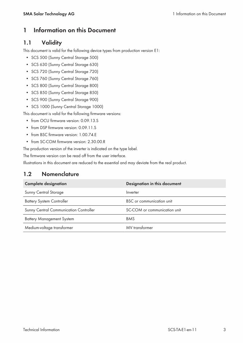
Figure 1: Design of the Inverter
Position Designation
A Inverter cabinet
B Interface cabinet
C Connection area
2.2 Devices of the Inverter
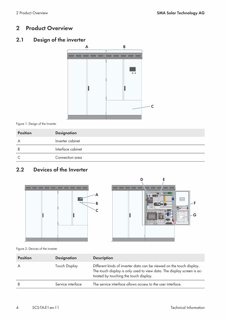
Figure 2: Devices of the inverter
Position Designation Description
A Touch Display Different kinds of inverter data can be viewed on the touch display.The touch display is only used to view data. The display screen is ac-tivated by touching the touch display.
B Service interface The service interface allows access to the user interface.
2 Product Overview SMA Solar Technology AG
Technical InformationSCS-TA-E1-en-114
Position Designation Description
C Key switch The key switch is used to switch the inverter on and off.
D DC switchgear The DC switchgear disconnects the inverter from the battery.
E Battery System Con-troller
The Battery System Controller is the communication interface of theinverter to the Battery Management System, the Fuel Save Controlleror the SCADA system.
F AC disconnection unit The AC disconnection unit disconnects the inverter from the MV trans-former.
G SC-COM The SC-COM allows for correct communication between the Bat-tery System Controller and the inverter.
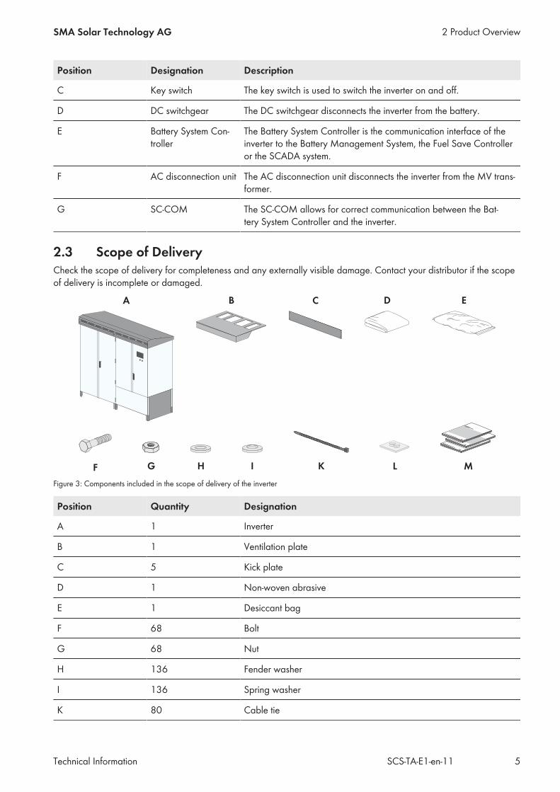
2.3 Scope of DeliveryCheck the scope of delivery for completeness and any externally visible damage. Contact your distributor if the scopeof delivery is incomplete or damaged.
Figure 3: Components included in the scope of delivery of the inverter
Position Quantity Designation
A 1 Inverter
B 1 Ventilation plate
C 5 Kick plate
D 1 Non-woven abrasive
E 1 Desiccant bag
F 68 Bolt
G 68 Nut
H 136 Fender washer
I 136 Spring washer
K 80 Cable tie
2 Product OverviewSMA Solar Technology AG
Technical Information 5SCS-TA-E1-en-11
Position Quantity Designation
L 3 Cable support sleeve (9.5 mm to 16 mm)
M 1 Circuit diagram, documentation, report
2 Product Overview SMA Solar Technology AG
Technical InformationSCS-TA-E1-en-116
3 Information for Installation
3.1 Climatic Conditions
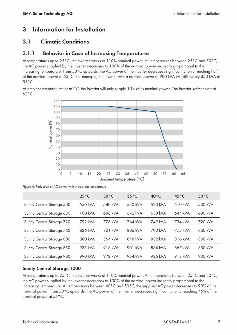
3.1.1 Behavior in Case of Increasing TemperaturesAt temperatures up to 25°C, the inverter works at 110% nominal power. At temperatures between 25°C and 50°C,the AC power supplied by the inverter decreases to 100% of the nominal power indirectly proportional to theincreasing temperature. From 50°C upwards, the AC power of the inverter decreases significantly, only reaching halfof the nominal power at 55°C. For example, the inverter with a nominal power of 900 kVA will still supply 450 kVA at55°C.At ambient temperatures of 60°C, the inverter will only supply 10% of its nominal power. The inverter switches off at62°C.
Figure 4: Reduction of AC power with increasing temperature
25°C 30°C 35°C 40°C 45°C 50°C
Sunny Central Storage 500 550 kVA 540 kVA 530 kVA 520 kVA 510 kVA 500 kVA
Sunny Central Storage 630 700 kVA 686 kVA 672 kVA 658 kVA 644 kVA 630 kVA
Sunny Central Storage 720 792 kVA 778 kVA 764 kVA 749 kVA 734 kVA 720 kVA
Sunny Central Storage 760 836 kVA 821 kVA 806 kVA 790 kVA 775 kVA 760 kVA
Sunny Central Storage 800 880 kVA 864 kVA 848 kVA 832 kVA 816 kVA 800 kVA
Sunny Central Storage 850 935 kVA 918 kVA 901 kVA 884 kVA 867 kVA 850 kVA
Sunny Central Storage 900 990 kVA 972 kVA 954 kVA 936 kVA 918 kVA 900 kVA
Sunny Central Storage 1000At temperatures up to 25°C, the inverter works at 110% nominal power. At temperatures between 25°C and 40°C,the AC power supplied by the inverter decreases to 100% of the nominal power indirectly proportional to theincreasing temperature. At temperatures between 40°C and 50°C, the supplied AC power decreases to 90% of thenominal power. From 50°C upwards, the AC power of the inverter decreases significantly, only reaching 45% of thenominal power at 55°C.
3 Information for InstallationSMA Solar Technology AG
Technical Information 7SCS-TA-E1-en-11

At ambient temperatures of 60°C, the inverter will only supply 9% of its nominal power. The inverter switches off at62°C.
Figure 5: Reduction of AC power with increasing temperature
25°C 40°C 50°C 55°C 60°C 62°C
Sunny Central Storage 1000 1,100 kVA 1,000 kVA 900 kVA 450 kVA 90 kVA 0 kVA
3 Information for Installation SMA Solar Technology AG
Technical InformationSCS-TA-E1-en-118

3.1.2 Requirements for the Mounting Location☐ The mounting location must be freely accessible at all times.☐ The fresh air requirement of the inverter amounting to 3,000 m3/h must be assured.☐ The mounting location must be below the maximum installation altitude.☐ The ambient temperature must be within the operating temperature range.☐ The fresh air must meet the 4S2 classification.
Air Quality Classification for Mechanically Active Substances
Ambient conditions for stationary application Class 4S2
a) Sand in air [mg/m3] 300
b) Dust (suspended matter) [mg/m3] 5.0
c) Dust (precipitation) [mg/m3] 20
Installation sites where appropriate measures are taken to keep dust levels to a mini-mum
x
Installation sites where no special measures have been taken to reduce the sand ordust levels and which are not located in the vicinity of sand or dust sources
x
The inverter is protected against salt spray in accordance with EN 60721-3-4 Class 4C2 and can be operated nearthe coast, for example.
Air Quality Classification for Chemically Active Substances
Ambient conditions for stationary application Class 4C2
Mean value Limiting value
a) Sea salt Occurrence of salt spray
b) Sulfur dioxide [mg/m3] 0.3 1.0
c) Hydrogen sulfide [mg/m3] 0.1 0.5
d) Chlorine [mg/m3] 0.1 0.3
e) Hydrogen chloride [mg/m3] 0.1 0.5
f) Hydrogen fluoride [mg/m3] 0.01 0.03
g) Ammonia [mg/m3] 1.0 3.0
h) Ozone [mg/m3] 0.05 0.1
i) Nitrogen oxides [mg/m3] 0.5 1.0
Installation sites in rural or densely populated areas withlittle industry and moderate traffic volume
x
Installation sites in densely populated areas with industryand high traffic volume
x
3.1.3 Supply Air and Exhaust AirThe inverter draws in the fresh air through the ventilation grids in the roof and blows it out again through the slits at therear of the inverter.
3 Information for InstallationSMA Solar Technology AG
Technical Information 9SCS-TA-E1-en-11
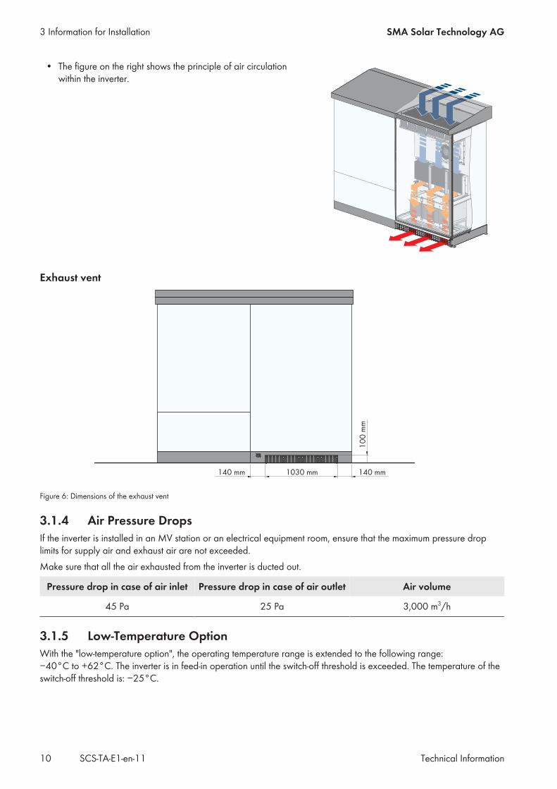
• The figure on the right shows the principle of air circulationwithin the inverter.
Exhaust vent
Figure 6: Dimensions of the exhaust vent
3.1.4 Air Pressure DropsIf the inverter is installed in an MV station or an electrical equipment room, ensure that the maximum pressure droplimits for supply air and exhaust air are not exceeded.Make sure that all the air exhausted from the inverter is ducted out.
Pressure drop in case of air inlet Pressure drop in case of air outlet Air volume
45 Pa 25 Pa 3,000 m3/h
3.1.5 Low-Temperature OptionWith the "low-temperature option", the operating temperature range is extended to the following range:−40°C to +62°C. The inverter is in feed-in operation until the switch-off threshold is exceeded. The temperature of theswitch-off threshold is: −25°C.
3 Information for Installation SMA Solar Technology AG
Technical InformationSCS-TA-E1-en-1110
If the ambient temperature falls below the switch-off threshold, the inverter switches to the operating state "Stop". Inaddition, the installed heating elements switch on to protect the components in the interior against too-lowtemperatures. As soon as the temperature exceeds the switch-on threshold, the inverter resumes feed-in operation. Thetemperature of the switch-on threshold is: −20°C.
3.2 Dimensions
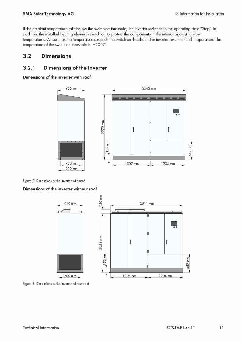
3.2.1 Dimensions of the InverterDimensions of the inverter with roof
Figure 7: Dimensions of the inverter with roof
Dimensions of the inverter without roof
Figure 8: Dimensions of the inverter without roof
3 Information for InstallationSMA Solar Technology AG
Technical Information 11SCS-TA-E1-en-11
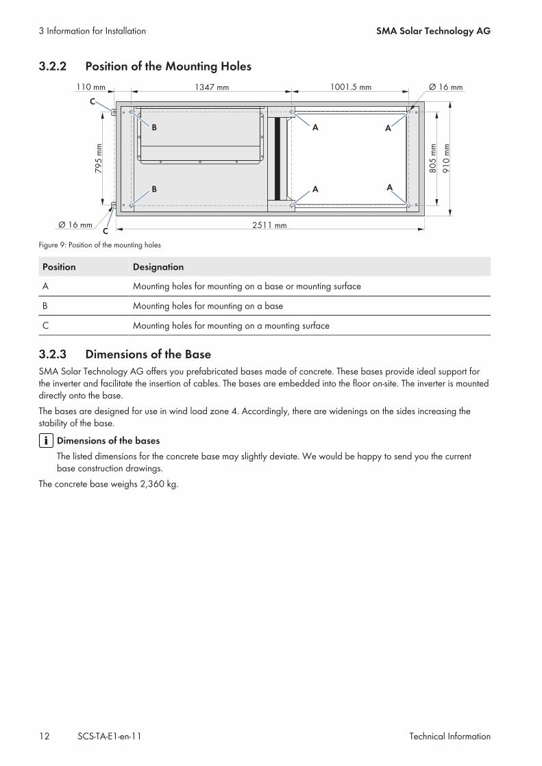
3.2.2 Position of the Mounting Holes
Figure 9: Position of the mounting holes
Position Designation
A Mounting holes for mounting on a base or mounting surface
B Mounting holes for mounting on a base
C Mounting holes for mounting on a mounting surface
3.2.3 Dimensions of the BaseSMA Solar Technology AG offers you prefabricated bases made of concrete. These bases provide ideal support forthe inverter and facilitate the insertion of cables. The bases are embedded into the floor on-site. The inverter is mounteddirectly onto the base.The bases are designed for use in wind load zone 4. Accordingly, there are widenings on the sides increasing thestability of the base.
Dimensions of the basesThe listed dimensions for the concrete base may slightly deviate. We would be happy to send you the currentbase construction drawings.
The concrete base weighs 2,360 kg.
3 Information for Installation SMA Solar Technology AG
Technical InformationSCS-TA-E1-en-1112
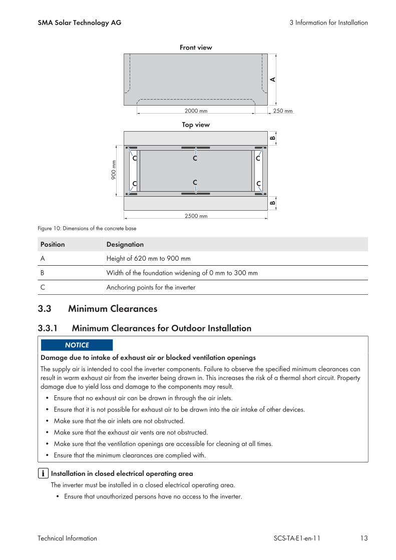
Figure 10: Dimensions of the concrete base
Position Designation
A Height of 620 mm to 900 mm
B Width of the foundation widening of 0 mm to 300 mm
C Anchoring points for the inverter
3.3 Minimum Clearances
3.3.1 Minimum Clearances for Outdoor Installation
Damage due to intake of exhaust air or blocked ventilation openingsThe supply air is intended to cool the inverter components. Failure to observe the specified minimum clearances canresult in warm exhaust air from the inverter being drawn in. This increases the risk of a thermal short circuit. Propertydamage due to yield loss and damage to the components may result.
• Ensure that no exhaust air can be drawn in through the air inlets.• Ensure that it is not possible for exhaust air to be drawn into the air intake of other devices.• Make sure that the air inlets are not obstructed.• Make sure that the exhaust air vents are not obstructed.• Make sure that the ventilation openings are accessible for cleaning at all times.• Ensure that the minimum clearances are complied with.
Installation in closed electrical operating areaThe inverter must be installed in a closed electrical operating area.
• Ensure that unauthorized persons have no access to the inverter.
3 Information for InstallationSMA Solar Technology AG
Technical Information 13SCS-TA-E1-en-11
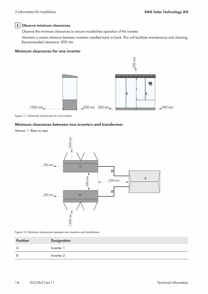
Observe minimum clearancesObserve the minimum clearances to ensure trouble-free operation of the inverter.Maintain a certain distance between inverters installed back to back. This will facilitate maintenance and cleaning.Recommended clearance: 800 mm
Minimum clearances for one inverter
Figure 11: Minimum clearances for one inverter
Minimum clearances between two inverters and transformerVersion 1: Rear to rear
Figure 12: Minimum clearances between two inverters and transformer
Position Designation
A Inverter 1
B Inverter 2
3 Information for Installation SMA Solar Technology AG
Technical InformationSCS-TA-E1-en-1114
Position Designation
C MV transformer and medium-voltage switchgear
D Cable route between inverter and MV transformer
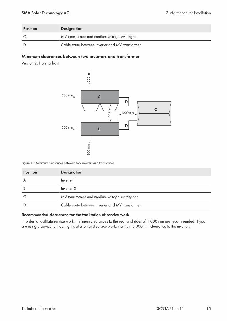
Minimum clearances between two inverters and transformerVersion 2: Front to front
Figure 13: Minimum clearances between two inverters and transformer
Position Designation
A Inverter 1
B Inverter 2
C MV transformer and medium-voltage switchgear
D Cable route between inverter and MV transformer
Recommended clearances for the facilitation of service workIn order to facilitate service work, minimum clearances to the rear and sides of 1,000 mm are recommended. If youare using a service tent during installation and service work, maintain 5,000 mm clearance to the inverter.
3 Information for InstallationSMA Solar Technology AG
Technical Information 15SCS-TA-E1-en-11
3.3.2 Minimum Clearances in Electrical Equipment Rooms
Damage due to intake of exhaust air or blocked ventilation openingsThe supply air is intended to cool the inverter components. Failure to observe the specified minimum clearances canresult in warm exhaust air from the inverter being drawn in. This increases the risk of a thermal short circuit. Propertydamage due to yield loss and damage to the components may result.
• Ensure that no exhaust air can be drawn in through the air inlets.• Ensure that it is not possible for exhaust air to be drawn into the air intake of other devices.• Make sure that the air inlets are not obstructed.• Make sure that the exhaust air vents are not obstructed.• Make sure that the ventilation openings are accessible for cleaning at all times.• Ensure that the minimum clearances are complied with.
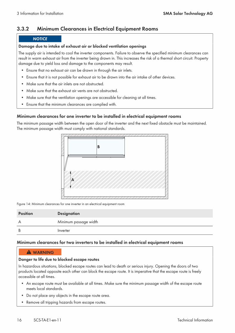
Minimum clearances for one inverter to be installed in electrical equipment roomsThe minimum passage width between the open door of the inverter and the next fixed obstacle must be maintained.The minimum passage width must comply with national standards.
Figure 14: Minimum clearances for one inverter in an electrical equipment room
Position Designation
A Minimum passage width
B Inverter
Minimum clearances for two inverters to be installed in electrical equipment rooms
Danger to life due to blocked escape routesIn hazardous situations, blocked escape routes can lead to death or serious injury. Opening the doors of twoproducts located opposite each other can block the escape route. It is imperative that the escape route is freelyaccessible at all times.
• An escape route must be available at all times. Make sure the minimum passage width of the escape routemeets local standards.
• Do not place any objects in the escape route area.• Remove all tripping hazards from escape routes.
3 Information for Installation SMA Solar Technology AG
Technical InformationSCS-TA-E1-en-1116
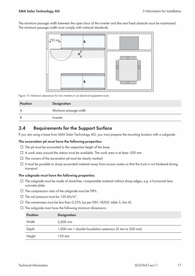
The minimum passage width between the open door of the inverter and the next fixed obstacle must be maintained.The minimum passage width must comply with national standards.
Figure 15: Minimum clearances for two inverters in an electrical equipment room
Position Designation
A Minimum passage width
B Inverter
3.4 Requirements for the Support SurfaceIf you are using a base from SMA Solar Technology AG, you must prepare the mounting location with a subgrade.
The excavation pit must have the following properties:☐ The pit must be excavated to the respective height of the base.☐ A work area around the station must be available. The work area is at least: 500 mm.☐ The corners of the excavation pit must be clearly marked.☐ It must be possible to dump excavated material away from access routes so that the truck is not hindered during
transport.
The subgrade must have the following properties:☐ The subgrade must be made of stone-free, compactable material without sharp edges, e.g. a horizontal lean
concrete plate.☐ The compression ratio of the subgrade must be 98%.☐ The soil pressure must be 150 kN/m2.☐ The unevenness must be less than 0.25% (as per DIN 18202: table 3, line 4).☐ The subgrade must have the following minimum dimensions:
Position Designation
Width 2,600 mm
Depth 1,000 mm + double foundation extension (0 mm to 300 mm)
Height 150 mm
3 Information for InstallationSMA Solar Technology AG
Technical Information 17SCS-TA-E1-en-11
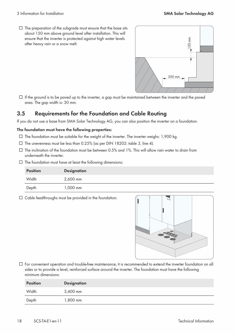
☐ The preparation of the subgrade must ensure that the base sitsabout 150 mm above ground level after installation. This willensure that the inverter is protected against high water levelsafter heavy rain or a snow melt.
☐ If the ground is to be paved up to the inverter, a gap must be maintained between the inverter and the pavedarea. The gap width is: 30 mm.
3.5 Requirements for the Foundation and Cable RoutingIf you do not use a base from SMA Solar Technology AG, you can also position the inverter on a foundation.
The foundation must have the following properties:☐ The foundation must be suitable for the weight of the inverter. The inverter weighs: 1,900 kg.☐ The unevenness must be less than 0.25% (as per DIN 18202: table 3, line 4).☐ The inclination of the foundation must be between 0.5% and 1%. This will allow rain water to drain from
underneath the inverter.☐ The foundation must have at least the following dimensions:
Position Designation
Width 2,600 mm
Depth 1,000 mm
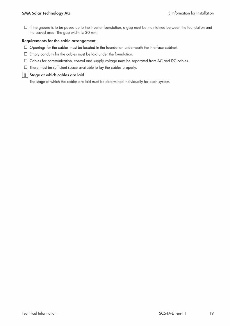
☐ Cable feedthroughs must be provided in the foundation.
☐ For convenient operation and trouble-free maintenance, it is recommended to extend the inverter foundation on allsides or to provide a level, reinforced surface around the inverter. The foundation must have the followingminimum dimensions:
Position Designation
Width 3,400 mm
Depth 1,800 mm
3 Information for Installation SMA Solar Technology AG
Technical InformationSCS-TA-E1-en-1118
☐ If the ground is to be paved up to the inverter foundation, a gap must be maintained between the foundation andthe paved area. The gap width is: 30 mm.
Requirements for the cable arrangement:☐ Openings for the cables must be located in the foundation underneath the interface cabinet.☐ Empty conduits for the cables must be laid under the foundation.☐ Cables for communication, control and supply voltage must be separated from AC and DC cables.☐ There must be sufficient space available to lay the cables properly.
Stage at which cables are laidThe stage at which the cables are laid must be determined individually for each system.
3 Information for InstallationSMA Solar Technology AG
Technical Information 19SCS-TA-E1-en-11
4 Transport
4.1 Safety during Transport and Mounting
Danger of crushing if raised or suspended loads tip over, fall or swayVibrations or careless or hasty lifting and transportation may cause the product to tip over or fall. This can result indeath or serious injury.
• All national standards and provisions for transport must be respected.• Always transport the product as close to the floor as possible.• Use all suspension points for transportation.• Avoid fast or jerky movements during transport.• Always maintain a sufficient safety distance from the product during transport.• All means of transport and auxiliary equipment used must be designed for the weight of the product. Weight:
1,900 kg.• Wear suitable personal protective equipment for all work on the product.• Disassemble the kick plates when transporting the inverter with a forklift, pallet truck or crane fork. Thus, the
contact surface of the product on the forks is sufficiently extended Disassembling and Mounting the Panels.
Damage to the frame construction of the inverter due to uneven support surfacePlacing the inverter on uneven surfaces can cause buckling so that the inverter doors will no longer close properly.This may lead to moisture and dust penetration into the inverter.
• Never place the inverter on an unstable, uneven surface even for a short period of time.• The unevenness of the support surface must be less than 0.25%.• The support surface must be suitable to take the weight of the inverter. Weight: 1,900 kg.• Do not transport the inverter with mounted kick plates.
4.2 Overview of Transport OptionsThe inverter comprises a compact enclosure which can be transported using either a long pallet truck, a forklift or acrane fork. Transport using a crane equipped with a suitable harness is also possible. Note that the selected means oftransportation must be suitable for the weight of the inverter. The weight of the inverter is: 1,900 kg.In the delivery condition, the panels in the base area have been removed so that the inverter can be transportedimmediately. The stable frame construction enables transport without the use of wooden pallets. In the standard scopeof delivery, the inverter is delivered standing on a wooden pallet. Therefore, a truck with a maximum overall height of4 m is sufficient for transport.
4 Transport SMA Solar Technology AG
Technical InformationSCS-TA-E1-en-1120
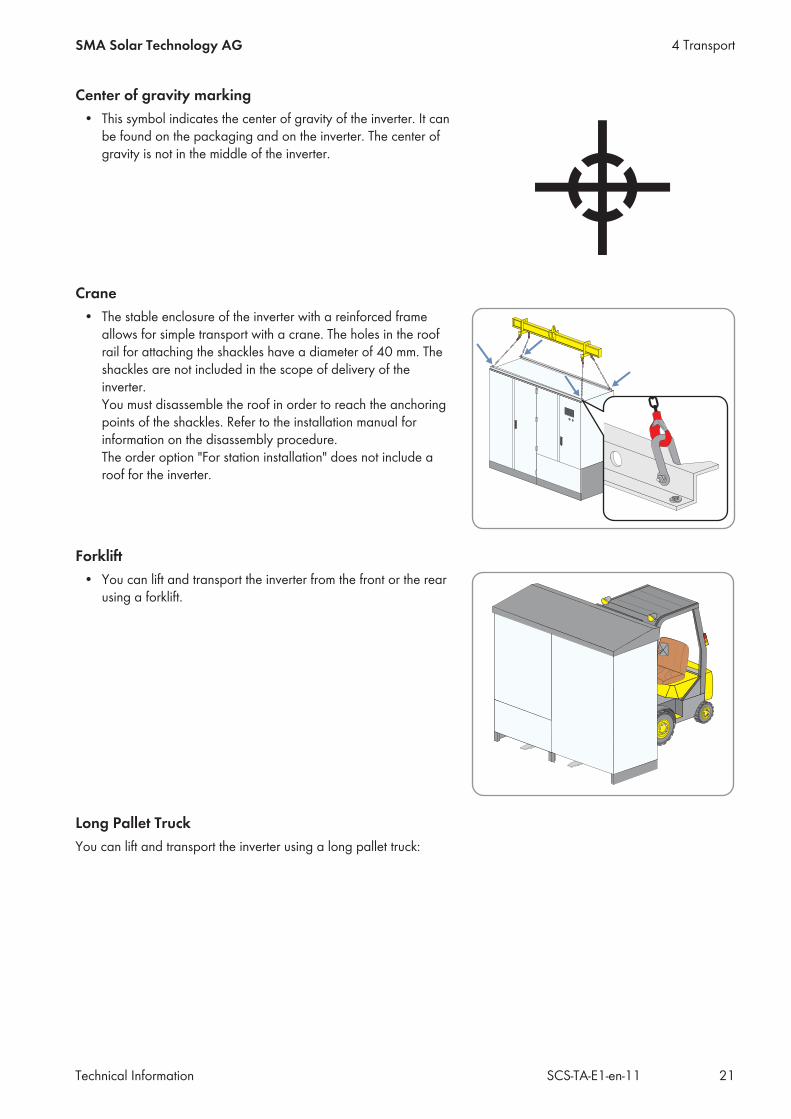
Center of gravity marking• This symbol indicates the center of gravity of the inverter. It can
be found on the packaging and on the inverter. The center ofgravity is not in the middle of the inverter.
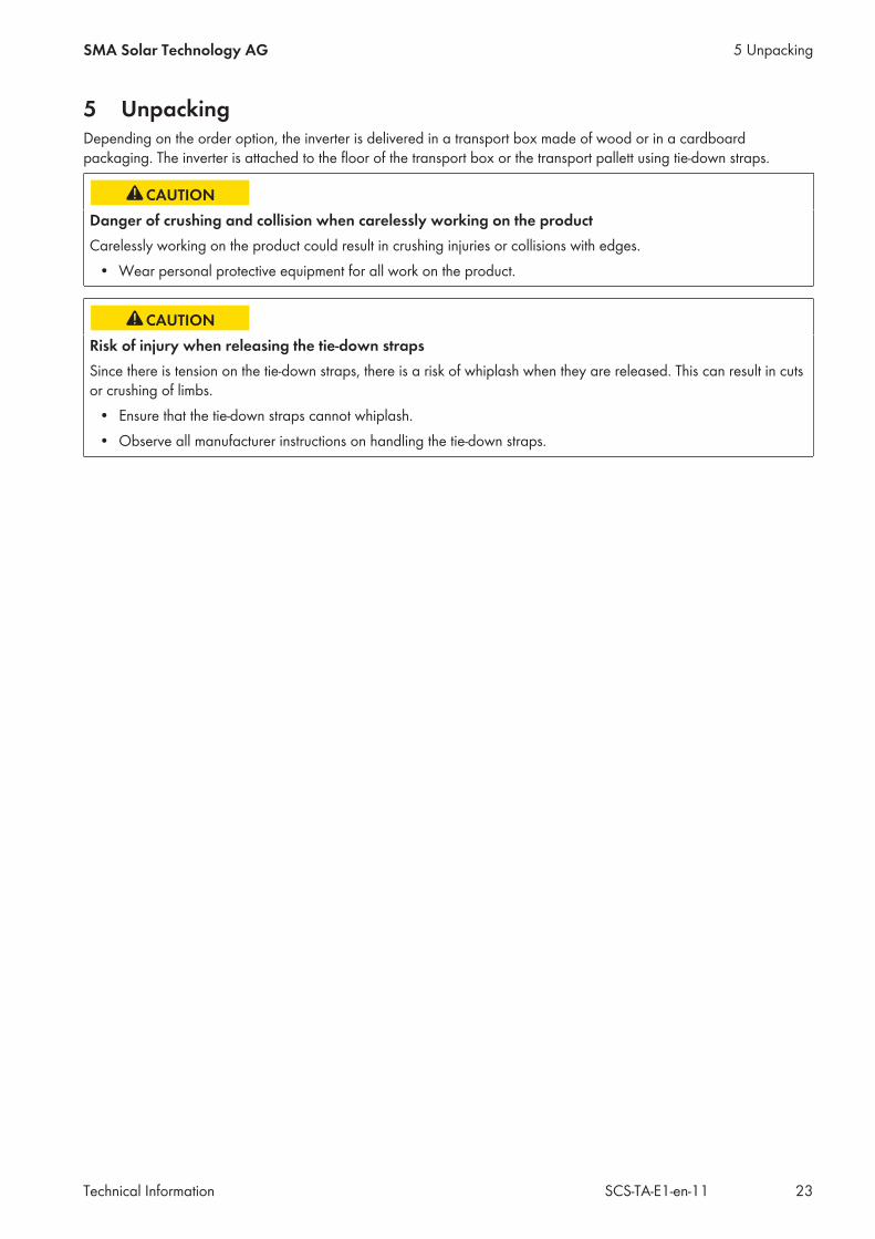
Crane• The stable enclosure of the inverter with a reinforced frame
allows for simple transport with a crane. The holes in the roofrail for attaching the shackles have a diameter of 40 mm. Theshackles are not included in the scope of delivery of theinverter.You must disassemble the roof in order to reach the anchoringpoints of the shackles. Refer to the installation manual forinformation on the disassembly procedure.The order option "For station installation" does not include aroof for the inverter.
Forklift• You can lift and transport the inverter from the front or the rear
using a forklift.
Long Pallet TruckYou can lift and transport the inverter using a long pallet truck:
4 TransportSMA Solar Technology AG
Technical Information 21SCS-TA-E1-en-11

• If the inverter is being transported on a wooden pallet, it canbe raised from either narrow side of the pallet.
• If the inverter is being transported without a wooden pallet, thepallet truck can only be moved underneath the invertercabinet. Be careful not to damage the side panels of theinverter when moving the pallet truck underneath.
Crane Fork• You can lift and transport the inverter from the front or the rear
using a crane fork.
4 Transport SMA Solar Technology AG
Technical InformationSCS-TA-E1-en-1122
5 UnpackingDepending on the order option, the inverter is delivered in a transport box made of wood or in a cardboardpackaging. The inverter is attached to the floor of the transport box or the transport pallett using tie-down straps.
Danger of crushing and collision when carelessly working on the productCarelessly working on the product could result in crushing injuries or collisions with edges.
• Wear personal protective equipment for all work on the product.
Risk of injury when releasing the tie-down strapsSince there is tension on the tie-down straps, there is a risk of whiplash when they are released. This can result in cutsor crushing of limbs.
• Ensure that the tie-down straps cannot whiplash.• Observe all manufacturer instructions on handling the tie-down straps.
5 UnpackingSMA Solar Technology AG
Technical Information 23SCS-TA-E1-en-11
6 Electrical Connection
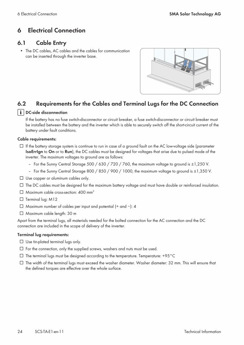
6.1 Cable Entry• The DC cables, AC cables and the cables for communication
can be inserted through the inverter base.
6.2 Requirements for the Cables and Terminal Lugs for the DC ConnectionDC-side disconnectionIf the battery has no fuse switch-disconnector or circuit breaker, a fuse switch-disconnector or circuit breaker mustbe installed between the battery and the inverter which is able to securely switch off the short-circuit current of thebattery under fault conditions.
Cable requirements:☐ If the battery storage system is continue to run in case of a ground fault on the AC low-voltage side (parameter
IsoErrIgn to On or to Run), the DC cables must be designed for voltages that arise due to pulsed mode of theinverter. The maximum voltages to ground are as follows:
– For the Sunny Central Storage 500 / 630 / 720 / 760, the maximum voltage to ground is ±1,250 V.– For the Sunny Central Storage 800 / 850 / 900 / 1000, the maximum voltage to ground is ±1,350 V.
☐ Use copper or aluminum cables only.☐ The DC cables must be designed for the maximum battery voltage and must have double or reinforced insulation.☐ Maximum cable cross-section: 400 mm2
☐ Terminal lug: M12☐ Maximum number of cables per input and potential (+ and −): 4☐ Maximum cable length: 30 m
Apart from the terminal lugs, all materials needed for the bolted connection for the AC connection and the DCconnection are included in the scope of delivery of the inverter.
Terminal lug requirements:☐ Use tin-plated terminal lugs only.☐ For the connection, only the supplied screws, washers and nuts must be used.☐ The terminal lugs must be designed according to the temperature. Temperature: +95°C☐ The width of the terminal lugs must exceed the washer diameter. Washer diameter: 32 mm. This will ensure that
the defined torques are effective over the whole surface.
6 Electrical Connection SMA Solar Technology AG
Technical InformationSCS-TA-E1-en-1124
6.3 Requirements for Cable Routing between MV Transformer andInverter
Risk of fire due to overheating of cables if different cable lengths are usedCables of differing lengths may cause the cables to overheat and catch fire. This can result in death or serious injury.
• All line conductors from the inverter to the MV transformer must be of the same length.• The cable length between the connection points must not exceed a maximum length. Maximum cable length:
15 m.
Cable and cable laying requirements:☐ The cables must be designed for the maximum voltages to ground.
For the Sunny Central Storage 500 / 630 / 720 / 760 / 800, the maximum voltage to ground is: ±1,450 V. For the Sunny Central Storage 850 / 900 / 1000, the maximum voltage to ground is: ±1,600 V.
☐ The cables must be designed for the maximum root-mean-square value. Maximum root-mean-square value: 800 V.☐ Do not attach more than four cables to each AC connecting plate.☐ Use copper or aluminum cables only.☐ Maximum cable cross-section: 300 mm².☐ All line conductor cables must be of the same length and must not exceed the maximum cable length. The
maximum cable length is 15 m.☐ The AC cables must be bundled in the three-phase system.☐ Between the MV transformer and the inverter, three separate cable routes for the AC cables must be available,
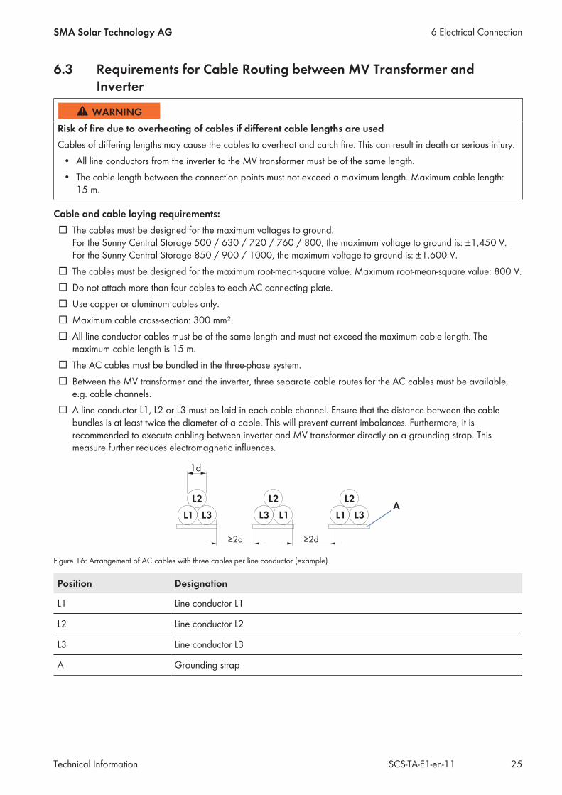
e.g. cable channels.☐ A line conductor L1, L2 or L3 must be laid in each cable channel. Ensure that the distance between the cable
bundles is at least twice the diameter of a cable. This will prevent current imbalances. Furthermore, it isrecommended to execute cabling between inverter and MV transformer directly on a grounding strap. Thismeasure further reduces electromagnetic influences.
Figure 16: Arrangement of AC cables with three cables per line conductor (example)
Position Designation
L1 Line conductor L1
L2 Line conductor L2
L3 Line conductor L3
A Grounding strap
6 Electrical ConnectionSMA Solar Technology AG
Technical Information 25SCS-TA-E1-en-11
6.4 Grounding ConceptIn accordance with the latest technology, the inverters are discharged to ground. As a result, leakage currents toground occur which must be taken into account when planning the PV power plant. The magnitude and distribution ofsuch leakage currents is influenced by the grounding concept of all devices in the PV power plant. It is thereforerecommended that e.g. for use of cameras and monitoring technology, signal transmission is executed in fiber-optictechnology. This will counteract possible interference sources.The recommended grounding of inverter and MV transformer in meshed design reduces leakage current levels.
6.5 External Supply VoltageThe inverter draws the necessary energy for internal power supply from the utility grid. The inverter can be connectedto an external supply voltage of 230 V/400 V (3/N/PE). The self-consumption is distributed asymmetrically over thethree line conductors and has a maximum value of 1,950 W. The connection of the neutral conductor is compulsorysince there are both three-phase and single-phase loads installed in the inverter. The inverter has five terminals with agrip range of 0.08 mm to 4 mm for connecting the external supply voltage.
6.6 Communication
6.6.1 Requirements for Data CablesYou can connect the Battery System Controller of the inverter to the Battery Management System using an Ethernetcable.
Network cable requirements:☐ The network cables must be shielded and pair-twisted.☐ The network cables must be of at least category 5 (CAT 5).☐ Maximum cable length: 100 m
Optical fibersYou can integrate the inverter in the network by means of direct optical fiber connection. For the order option withoptical fibers, a splice box is integrated in the inverter. The splice box features an SC-P plug to which the optical fibercan be directly connected.Another option for connecting the optical fiber to the splice box is an optical fiber pigtail. The optical fiber is spliced inthe splice box with the corresponding optical fiber pigtail. The optical fiber pigtail plug is connected to the SC-P plug ofthe splice box.
Optical fiber requirements:☐ The optical fiber cables must be equipped with a 50 μm multi-mode optical fiber.☐ The optical fibers must be fitted with a subscriber connector.
The optical fiber pigtail is not included in the scope of delivery.
6.6.2 External Fast StopThe inverter comes equipped with a fast stop input. You have the option of connecting an external switch to this faststop input which is activated via a 24 V signal. The external fast stop disconnects the inverter from the utility grid in lessthan 100 ms. The inverter has two terminals with a grip range of 0.08 mm to 4 mm for connecting the external faststop. The inverter is delivered with open terminals.The following options are available for configuring the external fast stop:
• External fast stop is deactivatedThe terminals of the active fast stop are bridged. The fast stop function is thus deactivated. You will need to bridgethe terminals if required.
6 Electrical Connection SMA Solar Technology AG
Technical InformationSCS-TA-E1-en-1126

• External fast stop operated with internal 24 V supplyAn external switch (break contact) is connected to the inverter terminals via the internal supply voltage in theinverter. When the switch is closed, the relay is activated and the inverter feeds into the grid. If the fast stop istripped, the switch opens and the relay is deactivated. The inverter is stopped and no longer feeds into the utilitygrid.With a conductor cross-section of 2.5 mm2, the maximum permissible conductor length is 130 m, and with aconductor cross-section of 1.5 mm2, the maximum permissible conductor length is 80 m.
• External fast stop operated with external 24 V supplyAn external switch (break contact) is connected to the inverter terminals via an external 24 V power supply.When the switch is closed, the relay is activated and the inverter feeds into the grid. If the fast stop is tripped, theswitch opens and the relay is deactivated. The inverter is stopped and no longer feeds into the utility grid.To use the external fast stop, an external 24 V power supply buffered for three to five seconds must be available.
The external fast stop must be connected in accordance with the circuit diagram. The external fast-stop function mustbe connected via a shielded cable.
Tripping the fast stopThe fast stop should only be tripped in case of imminent danger. Tripping of the fast stop does not entail fastdischarge of the capacitors. If the inverter is to be switched off and properly shut down via an external signal, theremote shutdown input is to be used.
6.6.3 Remote ShutdownBy means of remote shutdown, you can selectively shut down and switch off the inverter within approximately sixseconds, for example, from a control room. The function of the remote shutdown is similar to the stop function of thekey switch.The inverter has two terminals with a grip range of 0.08 mm to 4 mm for connecting the remote shutdown unit. Theremote shutdown unit can be connected to an external 24 V supply, or alternatively, the internal 24 V supply of thefast-stop function can be used.Use of the remote shutdown will only be possible if the parameter ExlStrStpEna is set to On.
6.6.4 Transformer ProtectionA fully hermetic protector can be connected to the inverter. This fully hermetic protector is integrated in the MVtransformer. If a fault occurs in the MV transformer, the inverter immediately shuts down. The inverter has two terminalswith a grip range of 0.08 mm to 4 mm for connecting the transformer monitoring unit. To use the transformermonitoring unit, an external supply voltage of 230 V ~ must be provided. The transformer monitoring unit must beconnected via a shielded cable. To deactivate this function, the associated parameter must be disabled.
6.6.5 Insulation monitoringIn order to ensure personal and system safety in an insulated, and hence non-grounded PV system, the insulation stateis monitored. If the inverter is equipped with insulation monitoring, the insulation resistance is calculated continuouslyby means of an active measurement procedure. Additional insulation monitoring is not necessary. Several insulationmeasuring devices in one system would interfere with one another and would distort the measurement results.
6 Electrical ConnectionSMA Solar Technology AG
Technical Information 27SCS-TA-E1-en-11
7 Preparing for CommissioningIn order to commission the inverter, the following conditions must be met:☐ Medium-voltage cables must be covered with sand.☐ AC and DC voltages must be available.☐ An area of 3,000 mm x 3,000 mm in front of the inverter must be reinforced.☐ The kick plates of the inverter must be attached.☐ One day before commissioning the desiccant bag enclosed ex works has to be replaced in the inverter cabinet.
7 Preparing for Commissioning SMA Solar Technology AG
Technical InformationSCS-TA-E1-en-1128


SMA Solar Technology
www.SMA-Solar.com


![[XLS] · Web view400 630 630 400 630 990 990 630 630 630 630 990 990 990 990 990 990 400 400 990 630 990 630 630 400 990 990 990 990 990 630 630 990 990 630 630 990 990 990 990 990](https://img.dokumen.tips/doc/110x75/5af695027f8b9a5b1e8f4d8f/xls-view400-630-630-400-630-990-990-630-630-630-630-990-990-990-990-990-990-400.jpg)