Embed Size (px)
Citation preview

Technical Glasses
Physical and Technical Properties
SCHOTT is an international technology group with 130 years of experience in the areas of specialty glasses and materials and advanced technologies. With our highquality products and intelligent solutions, we contribute to our customers’ success and make SCHOTT part of everyone’s life. For 130 years, SCHOTT has been shaping the future of glass technology. The Otto Schott Research Center in Mainz is one of the world’s leading glass research institutions. With our development center in Duryea, Pennsylvania (USA), and technical support centers in Asia, North America and Europe, we are present in close proximity to our customers around the globe.
2

Foreword
Apart from its application in optics, glass as a technical material has exerted a formative influence on the development of important technological fields such as chemistry, pharmaceutics, automotive, optics, optoelectronics and information technology. Traditional areas of technical application for glass, such as laboratory apparatuses, flat panel displays and light sources with their various requirements on chemical physical properties, have led to the development of a great variety of special glass types. Through new fields of application, particularly in optoelectronics, this variety of glass types and their modes of application have been continually enhanced, and new forming processes have been developed. The hermetic encapsulation of electronic components has given decisive impetus to development activities. Finally, the manufacture of highquality glassceramics from glass has opened entirely new dimensions, setting new standards for various technical applications.
To continuously optimize all commercial glasses and glass articles for existing applications and develop glasses and processes for new applications is the constant endeavor of SCHOTT. For such dynamic development, it is essential to be in close contact with the customers and to keep them as well informed as possible about glass.
SCHOTT Technical Glasses offers pertinent information in concise form. It contains general information for the determination and evaluation of important glass properties and also informs about specific chemical and physical characteristics and possible applications of the commercial technical glasses produced by SCHOTT. With this brochure, we hope to assist scientists, engineers, and designers in making the appropriate choice and make optimum use of SCHOTT products.
Users should keep in mind that the curves or sets of curves shown in the diagrams are not based on precision measurements but rather characterize and illustrate the typical property profiles of the respective glasses or glass types. Uptodate characteristic values of particular glasses can be found in the tables of this brochure or in separate data sheets.
Mainz, January 2014
3

Contents
1. Types of Technical Glasses . . . . . . . . . . . . . . . . . . . . . . . . . . . . . . . . . . . . . . . 6
Basic physical & chemical properties of specialty glass
2. Chemical Stability / Resistance of Glasses . . . . . . . . . . . . . . . . . . . . 8
2.1 Chemical reaction mechanisms with water, acids, and alkaline solutions . . . . . . . . . . . . . . . . . . . . . . . . . . . . . . . . . . . . . . . . . . . . . . 8
2.2 Determination of chemical stability . . . . . . . . . . . . . . . . . . . . . . . . . . . . . . . . . 9 2.3 The significance of chemical stability. . . . . . . . . . . . . . . . . . . . . . . . . . . . . . . 12
3. Mechanical and Thermal Properties . . . . . . . . . . . . . . . . . . . . . . . . .14
3.1 Viscosity . . . . . . . . . . . . . . . . . . . . . . . . . . . . . . . . . . . . . . . . . . . . . . . . . . . . . . . . . . 14 3.2 Strength . . . . . . . . . . . . . . . . . . . . . . . . . . . . . . . . . . . . . . . . . . . . . . . . . . . . . . . . . . 15 3.3 Elasticity . . . . . . . . . . . . . . . . . . . . . . . . . . . . . . . . . . . . . . . . . . . . . . . . . . . . . . . . . . 17 3.4 Coefficient of linear thermal expansion . . . . . . . . . . . . . . . . . . . . . . . . . . . . 17
4. Electrical Properties . . . . . . . . . . . . . . . . . . . . . . . . . . . . . . . . . . . . . . . . . . . . . 20
4.1 Volume resistivity . . . . . . . . . . . . . . . . . . . . . . . . . . . . . . . . . . . . . . . . . . . . . . . . . 20 4.2 Surface resistivity . . . . . . . . . . . . . . . . . . . . . . . . . . . . . . . . . . . . . . . . . . . . . . . . . 21 4.3 Dielectric properties . . . . . . . . . . . . . . . . . . . . . . . . . . . . . . . . . . . . . . . . . . . . . . . 21 4.4 Dielectric strength . . . . . . . . . . . . . . . . . . . . . . . . . . . . . . . . . . . . . . . . . . . . . . . . 23
5. Optical Properties . . . . . . . . . . . . . . . . . . . . . . . . . . . . . . . . . . . . . . . . . . . . . . . 24
5.1 Refraction of light . . . . . . . . . . . . . . . . . . . . . . . . . . . . . . . . . . . . . . . . . . . . . . . . . 24 5.2 Reflection of light . . . . . . . . . . . . . . . . . . . . . . . . . . . . . . . . . . . . . . . . . . . . . . . . . 24 5.3 Transmittance . . . . . . . . . . . . . . . . . . . . . . . . . . . . . . . . . . . . . . . . . . . . . . . . . . . . . 25 5.4 Color of glass . . . . . . . . . . . . . . . . . . . . . . . . . . . . . . . . . . . . . . . . . . . . . . . . . . . . . 27 5.5 Stress birefringence . . . . . . . . . . . . . . . . . . . . . . . . . . . . . . . . . . . . . . . . . . . . . . . 27
Application of specialty glass in select fields
6. Highly Resistant Glasses for Laboratory, Pharma and ... . . . . . . . . . . . . . . . . . . . . . . . . . . . . . . . . . . . . . . . . . . . . . . . . . . . 28
6.1 DURAN® . . . . . . . . . . . . . . . . . . . . . . . . . . . . . . . . . . . . . . . . . . . . . . . . . . . . . . . . . . 28 6.2 FIOLAX® . . . . . . . . . . . . . . . . . . . . . . . . . . . . . . . . . . . . . . . . . . . . . . . . . . . . . . . . . . 29 6.3 BOROFLOAT® 33/SUPREMAX® . . . . . . . . . . . . . . . . . . . . . . . . . . . . . . . . . . . . . 31
7. Flat Glasses for Home Appliances, Architecture and Safety . . . . . . . . . . . . . . . . . . . . . . . . . . . . . . . . . . . . . . . . 32
7.1 AMIRAN® . . . . . . . . . . . . . . . . . . . . . . . . . . . . . . . . . . . . . . . . . . . . . . . . . . . . . . . . . 33 7.2 MIRONA® . . . . . . . . . . . . . . . . . . . . . . . . . . . . . . . . . . . . . . . . . . . . . . . . . . . . . . . . . 33 7.3 MIROGARD® . . . . . . . . . . . . . . . . . . . . . . . . . . . . . . . . . . . . . . . . . . . . . . . . . . . . . . 33
4
7.4 PYRAN®, PYRANOVA®, NOVOLAY® secure & PYRANOVA® secure . . . . 33 7.5 Processed flat glass for home appliances . . . . . . . . . . . . . . . . . . . . . . . . . . . 34 7.6 Special solutions for home appliances . . . . . . . . . . . . . . . . . . . . . . . . . . . . . 34 7.7 Insulated glass doors for commercial refrigeration . . . . . . . . . . . . . . . . . . 35 7.8 Radiation shielding glasses . . . . . . . . . . . . . . . . . . . . . . . . . . . . . . . . . . . . . . . . 35
8. Thin Glasses / UltraThin Glasses for Electronics and More . . . . . . . . . . . . . . . . . . . . . . . . . . . . . . . . . . . . . . . . . . . . . . . . . . . . . . . . . . 36
8.1 BOROFLOAT® 33 . . . . . . . . . . . . . . . . . . . . . . . . . . . . . . . . . . . . . . . . . . . . . . . . . . 36 8.2 Xensation® Cover . . . . . . . . . . . . . . . . . . . . . . . . . . . . . . . . . . . . . . . . . . . . . . . . . 36 8.3 Thin glasses . . . . . . . . . . . . . . . . . . . . . . . . . . . . . . . . . . . . . . . . . . . . . . . . . . . . . . . 36 8.4 Thin glass processing . . . . . . . . . . . . . . . . . . . . . . . . . . . . . . . . . . . . . . . . . . . . . . 38 8.5 Antireflective glasses for technical applications
(CONTURAN®/DARO) . . . . . . . . . . . . . . . . . . . . . . . . . . . . . . . . . . . . . . . . . . . . . 40
9. Glasses for Joinings . . . . . . . . . . . . . . . . . . . . . . . . . . . . . . . . . . . . . . . . . . . . . . 44
9.1 Sealing glasses . . . . . . . . . . . . . . . . . . . . . . . . . . . . . . . . . . . . . . . . . . . . . . . . . . . 44 9.2 Glass and glassceramic sealants for technical ceramics . . . . . . . . . . . . . 51 9.3 Glass and glassceramic sealants for solid oxide fuel cells (SOFC) /
sold elecholyzer cells / SO EC . . . . . . . . . . . . . . . . . . . . . . . . . . . . . . . . . . . . . . 52 9.4 Solder glasses . . . . . . . . . . . . . . . . . . . . . . . . . . . . . . . . . . . . . . . . . . . . . . . . . . . . . 53 9.5 Passivation glasses . . . . . . . . . . . . . . . . . . . . . . . . . . . . . . . . . . . . . . . . . . . . . . . . 56
10. GlassCeramics for Industrial Applications and Home Appliances . . . . . . . . . . . . . . . . . . . . . . . . . . . . . . . . . . . . . . . . . . 58
10.1 Introduction to glassceramics . . . . . . . . . . . . . . . . . . . . . . . . . . . . . . . . . . . . . 58 10.2 PYRAN® Platinum . . . . . . . . . . . . . . . . . . . . . . . . . . . . . . . . . . . . . . . . . . . . . . . . . 60 10.3 ZERODUR® . . . . . . . . . . . . . . . . . . . . . . . . . . . . . . . . . . . . . . . . . . . . . . . . . . . . . . . . 60 10.4 NEXTREMA™ . . . . . . . . . . . . . . . . . . . . . . . . . . . . . . . . . . . . . . . . . . . . . . . . . . . . . 60
11 Optical Materials . . . . . . . . . . . . . . . . . . . . . . . . . . . . . . . . . . . . . . . . . . . . . . . . . 62
11.1 Introduction of Advanced Optics . . . . . . . . . . . . . . . . . . . . . . . . . . . . . . . . . . 62 11.2 Product overview . . . . . . . . . . . . . . . . . . . . . . . . . . . . . . . . . . . . . . . . . . . . . . . . . 62
Appendix
Glass Types . . . . . . . . . . . . . . . . . . . . . . . . . . . . . . . . . . . . . . . . . . . . . . . . . . . . . . . . . . . . . 66
Glasses for the Chemical Industry and Electrical Engineering – Sealing Glasses . . . . . . . . . . . . . . . . . . . . . . . . . 68
Your Contacts . . . . . . . . . . . . . . . . . . . . . . . . . . . . . . . . . . . . . . . . . . . . . . . . . . . . . . . . . . 73
Literature . . . . . . . . . . . . . . . . . . . . . . . . . . . . . . . . . . . . . . . . . . . . . . . . . . . . . . . . . . . . . . . . 74
5

1. Types of Technical Glasses
In the following, technical glasses are understood to be special glasses manufactured in the form of tubes, rods, hollow vessels and a variety of special shapes, as well as flat glass and glass powder for use mainly in chemistry, lab oratory technology, pharmaceuticals, optoelectronics, and household appliance technology.
Glasses for purely optical applications are usually distinguished from these technical glasses by their special manufacturing processes and by their special compositional ranges.
For the purposes of classification, the multitude of technical glasses can be roughly arranged in the following six groups, according to their oxide composition (in weight percent). It should be noted, however, that certain glasses fall between these groups, and others completely outside of the groups, and therefore cannot be classified as belonging to these types.
Borosilicate glasses
Characteristic of this type is the presence of substantial amounts of silica (SiO2) and boric oxide (B2O3 > 8 %) as glass network formers.
The amount of boric oxide affects the glass properties in a particular way. Apart from the highly resistant varieties (B2O3 up to a maximum of 13 %), there are others that – due to the different way in which the boric oxide is incorporated into the structural network – have only low chemical resistance (B2O3 content over 15 %). Hence we differentiate between the following subtypes.
Non-alkaline earth borosilicate glass (borosilicate glass 3.3)The B2O3 content for borosilicate glass is typically 12 – 13 % and the SiO2 content over 80 %. High chemical durability and low thermal expansion (3.3 x 10⁻⁶/K) – the lowest of all commercial glasses for largescale technical applications – make this a multitalented glass material.
Highgrade SCHOTT borosilicate flat glasses are used in a wide variety of industries, mainly for technical applications that require either good thermal resistance, excellent chemical durability, or high light transmission in combination with a pristine surface quality.
Other typical applications for different forms of borosilicate glass include glass tubing, glass piping, glass con tainers, etc. especially for the chemical industry.
BOROFLOAT® 33, SUPREMAX® and DURAN® belong to this glass family.
Alkaline earth containing borosilicate glassesIn addition to about 75 % SiO2 and 8 – 12 % B2O3, these glasses contain up to 5 % alkaline earths and alumina (Al2O3). To this subtype of slightly softer glasses (as compared with nonalkaline earth borosilicate glass), which have thermal expansion of between 4.0 – 5.0 x 10⁻⁶/K, belong the chemically highly resistant varieties FIOLAX® 8412 and 8414 (“neutral glasses”), and SUPRAX® and 8488.
High-borate borosilicate glassesGlasses containing 15 – 25 % B2O3, 65 – 70 % SiO2, and smaller amounts of alkalis and Al2O3 as additional components, have low softening points and low thermal expansion. Sealability to metals in the expansion range of tungstenmolybdenum and high electrical insulation are their most important features. The increased B2O3 content reduces the chemical resistance; in this respect, highborate borosilicate glasses differ widely from nonalkaline earth and alkaline earth borosilicate glasses.Examples: 8245, 8250, 8337B, 8487.
Aluminosilicate glasses
Alkaline earth aluminosilicate glassesCharacteristically, these glasses are free of alkali oxides and contain 15 – 25 % Al2O3, 52 – 60 % SiO2, and about 15 % alkaline earths. Very high transformation temperatures and softening points are typical features. Main fields of application are glass bulbs for halogen lamps, hightemperature thermometers, thermally and electrically highly loadable film resistors and combustion tubes. Examples: Halogen lamp glass types 8252 and 8253.
Alkali aluminosilicate glassesThe Al2O3 content of alkali aluminosilicate glasses is typically 10 – 25 % and the alkali content over 10 %. The high alkali content prepares the glass for ion exchange with bigger alkali ions in order to improve the surface compressive strength. High transformation temperatures and outstanding mechanical properties, e. g. hardness and scratch
6

behavior, are characteristic features of this glass type.Examples: Ion exchange glass types AS87 (8787) and LAS80 (8785).
Aluminoborosilicate glasses
Alkaline-free aluminoborosilicate glassesTypically, these glasses essentially consist of 55 – 65 % SiO2, 15 – 20 % Al2O3, 5 – 10 % B2O3 and about 10 to 15 % alkaline earth oxides, without any additions of alkali oxides. A low coefficient of thermal expansion combined with high transformation temperature and good chemical stabilities makes them especially useful as substrate glasses for flat panel displays.Examples: substrate glasses for TFT displays AF37 (8264) and AF32 (8266).
Alkalilead silicate glasses
Such glasses typically contain over 10 % lead oxide (PbO). Lead glasses containing 20 – 30 % PbO, 54 – 58 % SiO2 and about 14 % alkalis are highly insulating and therefore of
great importance in electrical engineering. They are used in lamp stems.
Lead oxide is also of great importance as an Xray protective component in radiation shielding glasses.
Alkali alkaline earth silicate glasses (sodalime glasses)
This is the oldest glass type. It comprises flat glasses (window glass) and container glasses, which are produced in large batches. Such glasses contain about 15 % alkali (usually Na2O), 13 – 16 % alkaline earths (CaO + MgO), 0 – 2 % Al2O3 and about 71 % SiO2.
Different versions of the basic composition can also contain significant amounts of BaO with reduced alkali and alkaline earth content. Example: 8350.
Also belonging to this group are glasses with higher BaO content for Xray protection such as those used in technical applications requiring radiation shielding. On a broader plane, certain crystal glasses (drinking glasses) can also be included.
LASglassceramics
Due to their outstanding properties, crystallizable glasses in the LithiumAluminiumSilicate (LAS) system have achieved high commercial significance. Key properties are very low, even zero thermal expansion, optical transparency and high chemical resistance. Characteristically, these glasses contain 3 – 6 % Li2O, 18 – 25 % Al2O3, 58 – 75 % SiO2 (crystal constituents), 2 – 6 % TiO2 + ZrO2 (nucleating agents) and about 2 % alkaline and alkaline earths to improve glass melting (residual glass formers). MgO, ZnO and P2O5 can also enter the crystalline phase to form solid solution crystals. Coloration of glassceramics (by adding coloring oxides like V2O5, Fe2O3, CoO, NiO, MnO2) creates black CERAN® cooktop panels. Transparent glassceramics are used in ROBAX® fireplace windows, CERAN CLEARTRANS® cooktop panels with underside coating, PYRAN® Platinum fire resistant glazings, ZERODUR® precision articles and a broad range of special applications under the trade name NEXTREMA®. Examples: CERAN HIGHTRANSeco® 8712, ROBAX® 8724
Ingredients for the production of special glasses
1
7

2. Chemical Stability / Resistance of Glasses
Characteristically, glass is highly resistant to water, salt solutions, acids, and organic substances. In this respect, it is superior to most metals and plastics. Glass is attacked to a significant degree – particularly at higher temperatures – only by hydrofluoric acid, strong alkaline solutions, and concentrated phosphoric acid.
Chemical reactions with glass surfaces, induced by exchange, erosion or adsorption processes, can cause most diversified effects ranging from virtually invisible surface modifications to opacity, staining, thin films with interference colors, crystallization, bubbles, rough or smooth ablation, to name but a few. These changes are often limited to the glass surface, but in extreme cases they can completely destroy or dissolve the glass. Glass composition, contact medium, and operating conditions will decide to what extent such chemical attacks are technically significant.
2.1 Chemical reaction mechanisms with water, acids, and alkaline solutions
Chemical stability is to be understood as the resistance of the glass surface to chemical attack by defined agents, whereby temperature, exposure time, and the condition of the glass surface play important roles.
Every chemical attack on glass involves water or its dissociation product, i.e. H+ or OH– ions. For this reason, we differentiate between hydrolytic (water), acid and alkali resistance. By water or acid attacks, small amounts of (mostly mono or divalent) cations are leached out. In resistant glasses, a very thin layer of silicagel then forms on the surface, which normally inhibits further attack (Figure 1a, b). Hydrofluoric acid, alkaline solutions and in some cases phosphoric acid, however, gradually destroy the silica framework and thus ablate the glass surface in total (see Figure 1c). In contrast, waterfree (i.e. organic) solutions do not react with glass.
Chemical reactions are often increased or decreased by the presence of other components. Alkali attack on glass is thus hindered by certain ions, particularly those of aluminum. On the other hand, complexforming compounds such as
EDTA, tartaric acid, citric acid, and others increase solubility. In general terms, the glass surface reacts with solutions which induce smallscale exchange reactions and/or adsorptions. Such phenomena are observed, for example, in highvacuum technology when residual gases are removed, or in certain inorganic chemical operations when small amounts of adsorbed chromium, resulting from treatment with chromic acid, are removed.
Fig. 1. Attack by water, acids and alkaline solutions on chemically resistant glass as a function of time
Rele
ase
in m
g N
a 2O/g
gla
ss g
rain
s ––
>
Time in h ––>0 2 4 6 8
0.01
0.00
0.02
0.03
0.04
a: Water attack
Wei
ght
loss
in m
g/10
0 cm
2 ––
>
Time in h ––>0 2 4 6 8
0.20
0.00
0.40
0.60
b: Acid attack
Wei
ght
loss
in m
g/10
0 cm
2 ––
>
Time in h ––>0 2 4 6 8
80
0
160
240
c: Alkali attack
8

Because acid and alkali attacks on glass are fundamentally different, silicagel layers produced by acid attack ob viously are not necessarily effective against alkali solutions and may be destroyed. Conversely, the presence of ions that inhibit an alkali attack does not necessarily represent protection against acids and water. The most severe chemical exposure is therefore the alternating treatment with acids and alkaline solutions. As in all chemical reactions, the intensity of interaction increases rapidly with increasing temperature (Figures 27 and 28).
In the case of truly ablative solutions such as hydrofluoric acid, alkaline solutions, or hot concentrated phosphoric acid, the rate of attack increases rapidly with increasing concentration (Figure 2). As can be seen in Figure 3, this is different for the other frequently applied acids.
2.2 Determination of chemical stability
In the course of time, many analysis methods have been suggested for determining the chemical stability of glass. In most cases, it is the glass surface that is analyzed either in its “as delivered” condition (with the original firepolished surface) or as a basic material with its firepolished surface removed by mechanical or chemical ablation, or after crushing.
The standardized DIN* test methods, which are uni versally and easily applicable, are the most reliable analysis methods. They include the determination of hydrolytic resistance (by two graintitration methods and one surface method), of acid resistance to hydro chloric acid, and of alkali resistance to a mixture of alkaline solutions.
Wei
ght
loss
aft
er 3
h in
mg/
100
cm2
––>
ph ––>
10
0
20
30
40
50
0 8 10 12 14
Att
acke
d la
yer
in µ
m –
–>
Acid concentration (molarity) ––>0 5 10 15 20
CH3COOH
HNO3
H2SO4
HCI Temperature: 100 °C Time: 1 h
0.00
0.01
0.02
0.03
Fig. 2. Alkali attack on DURAN®/BOROFLOAT® 33/SUPREMAX® related to pH value at 100 °C
Fig. 3. Acid attack on DURAN®/BOROFLOAT® 33/SUPREMAX® as a function of concentration
Hydrolytic classes
Acid consumption of 0.01 mol/l hydrocholric acid per g glass grains ml/g
Base equivalent as Na2O per g glass grains µg/g
Possible designation
1 up to 0.10 up to 31 very highly resistant glass
2 above 0.10 up to 0.20 above 31 up to 62 highly resistant glass
3 above 0.20 up to 0.85 above 62 up to 264 medium resistant glass
4 above 0.85 up to 2.0 above 264 up to 620 low resistant glass
5 above 2.0 up to 3.5 above 620 up to 1085 very low resistant glass
Table 1. Hydrolytic classes of DIN ISO 719
* Deutsches Institut für Normung e. V. German Institute for Standardization
2
9
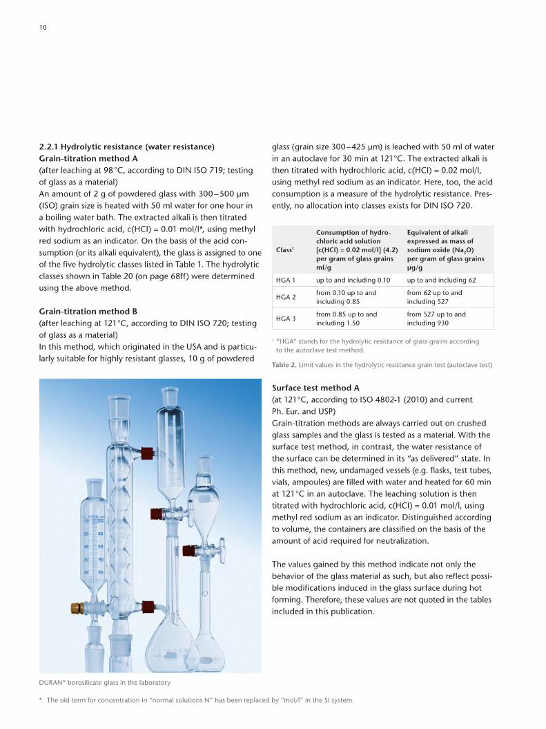
2.2.1 Hydrolytic resistance (water resistance)Grain-titration method A(after leaching at 98 °C, according to DIN ISO 719; testing of glass as a material)An amount of 2 g of powdered glass with 300 – 500 µm (ISO) grain size is heated with 50 ml water for one hour in a boiling water bath. The extracted alkali is then titrated with hydrochloric acid, c(HCI) = 0.01 mol/l*, using methyl red sodium as an indicator. On the basis of the acid consumption (or its alkali equiva lent), the glass is assigned to one of the five hydrolytic class es listed in Table 1. The hydrolytic classes shown in Table 20 (on page 68ff) were determined using the above method.
Grain-titration method B(after leaching at 121 °C, according to DIN ISO 720; testing of glass as a material)In this method, which originated in the USA and is particularly suitable for highly resistant glasses, 10 g of powdered
glass (grain size 300 – 425 µm) is leached with 50 ml of water in an autoclave for 30 min at 121 °C. The extracted alkali is then titrated with hydrochloric acid, c(HCI) = 0.02 mol/l, using methyl red sodium as an indicator. Here, too, the acid consumption is a measure of the hydrolytic resistance. Presently, no allocation into classes exists for DIN ISO 720.
Class1
Consumption of hydro-chloric acid solution [c(HCl) = 0.02 mol/l] (4.2) per gram of glass grains ml/g
Equivalent of alkali expressed as mass of sodium oxide (Na2O) per gram of glass grains µg/g
HGA 1 up to and including 0.10 up to and including 62
HGA 2from 0.10 up to and including 0.85
from 62 up to and including 527
HGA 3from 0.85 up to and including 1.50
from 527 up to and including 930
1 “HGA” stands for the hydrolytic resistance of glass grains according to the autoclave test method.
Table 2. Limit values in the hydrolytic resistance grain test (autoclave test)
Surface test method A(at 121 °C, according to ISO 48021 (2010) and current Ph. Eur. and USP)Graintitration methods are always carried out on crushed glass samples and the glass is tested as a material. With the surface test method, in contrast, the water resistance of the surface can be determined in its “as delivered” state. In this method, new, undamaged vessels (e.g. flasks, test tubes, vials, ampoules) are filled with water and heated for 60 min at 121 °C in an autoclave. The leaching solution is then titrated with hydrochloric acid, c(HCI) = 0.01 mol/l, using methyl red sodium as an indicator. Distinguished according to volume, the containers are classified on the basis of the amount of acid required for neutralization.
The values gained by this method indicate not only the behavior of the glass material as such, but also reflect possible modifications induced in the glass surface during hot forming. Therefore, these values are not quoted in the tables included in this publication.
DURAN® borosilicate glass in the laboratory
* The old term for concentration in “normal solutions N” has been replaced by “mol/l” in the SI system.
10

Surface test method B(at 121 °C, according to ISO 48022 (2010) and current Ph. Eur.)Graintitration methods are always carried out on crushed glass samples and the glass is tested as a material. With the surface test method, in contrast, the water resistance of the surface can be determined in its “as delivered” state. In this method, new, undamaged vessels (e.g. flasks, test tubes, vials, ampoules) are filled with water and heated for 60 min at 121 °C in an autoclave. The leaching solution is then analyzed by using flame atomic emission or adsorption spectrometry (flame spectrometry). This is a direct and precise method for quantifying the specific leached ions in the solution. Distinguished according to volume, the containers are classified according to the mean value of the concentration of the oxides.
2.2.2 Acid resistance, according to DIN 12116The glass surface to be tested is boiled for 6 h in 20 % hydrochloric acid [c(HCI) = 6 mol/l], and the loss in weight is determined in mg/100 cm2. Using the half loss in weight, the glasses are then classified as follows:
Acid class DesignationHalf loss in weight after 6 h mg/100 cm2
1 highly acid resistant up to 0.7
2 acid resistant above 0.7 up to 1.5
3 slight acid attack above 1.5 up to 15
4 high acid attack above 15
Table 3. Acid classes
Acid classes for glasses manufactured by SCHOTT are listed in Table 20, p. 68ff.
2.2.3 Alkali resistance, according to DIN ISO 695To determine the alkali resistance, glass surfaces are subjected to a 3 h treatment in boiling aqueous solution consisting of equal volumes of sodium hydroxide, c(NaOH) = 1 mol/l and sodium carbonate, c(Na2CO3) = 0.5 mol/l. The loss in weight is then determined, and the glasses are classified as follows:
Alkali class DesignationLoss in weight after 3 h mg/100 cm2
1 low alkali attack up to 75
2 slight alkali attack above 75 up to 175
3 high alkali attack above 175
Table 4. Alkali classes
Alkali classes for glasses manufactured by SCHOTT are listed in Table 20, p. 68ff.
The following borosilicate glasses have particularly high chemical resistance: DURAN®/BOROFLOAT® 33/ SUPREMAX® (8330), SUPRAX® (8488), FIOLAX® clear (8412), FIOLAX® amber (8414) and PYRAN® S (8341); see Table 6, p. 30.
FIOLAX® highly chemical resistant glass for save primary packaging in the pharmaceutical industry
2
11
2.3 The significance of chemical stability
2.3.1 Corrosion resistance in chemical plant applicationsFor such applications, the glasses must be resistant to the various chemical solutions to such a degree that manifold reactions can take place without running the risk of damaging the laboratory glass or the equipment by strong ablation. Moreover, no interfering amounts of glass components must be released into the reaction mixture. Attack by acids is of particular importance, both in laboratories and in chemical technology. Here, borosilicate glasses with their high acid resistance are superior to other materials. Up to the boiling point, their reactivity is very low; it then increases with increasing acid concentration, but decreases again at higher concentrations (Figure 3). The alkali attack, in con
trast, increases exponentially with increasing alkali concentration (Figure 2).
A comparison of the effect of the alkaline mixture (concentration of alkaline components about 1 mol/l) with the effect of 6 mol/l hydrochloric acid (the most aggressive acid used in acid resistance tests) under standard conditions shows that the alkali attack increases by a factor of 1000 after extended exposure.
2.3.2 Release of glass constituentsIn various processes of chemical technology, pharmaceuticals, and laboratory work, the material glass is expected to release no constituents (or a very minimum) into the reacting solutions or stored specimens.
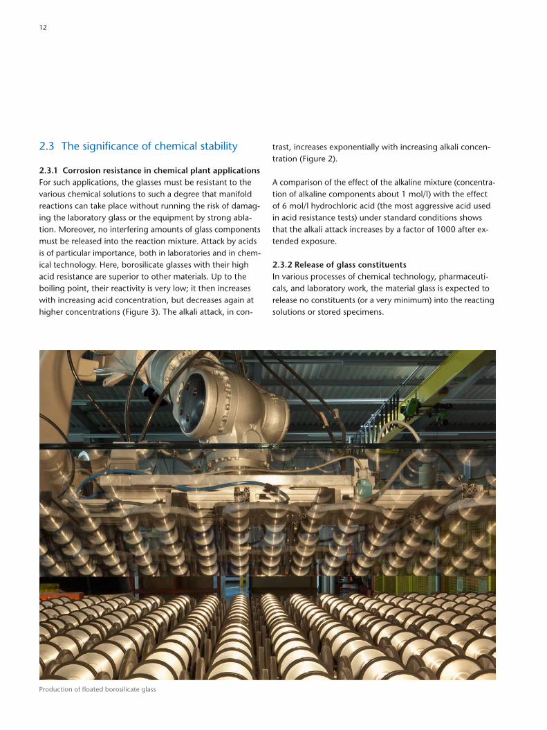
Production of floated borosilicate glass
12

Because even highly resistant materials such as nonalkaline earth and alkaline earth borosilicate glasses react to a very small degree with the surrounding media, the fulfillment of this requirement is a question of quantity and detection limits. Concentrations of 10–6 – 10–9 (i.e. trace amounts), which are measurable today with highly sophisticated analytical instruments, can be released even from borosilicate glasses in the form of SiO2, B2O3, and Na2O, depending on the conditions. However, solutions in contact with highgrade colorless DURAN® laboratory glass will not be contaminated by Fe, Cr, Mn, Zn, Pb, or other heavymetal ions.
2.3.3 Undesirable glass surface changesWhen an appreciable interaction between a glass surface and aqueous solutions occurs, there is an ion exchange in which the easily soluble glass components are replaced by H+ or OH– ions. This depletion of certain glass components in the surface leads to a corresponding enrichment in silica, which is poorly soluble, and thus to the formation of a socalled silicagel layer. This layer proves, in most cases, to be more resistant than the base glass. When its thickness exceeds about 0.1 – 0.2 µm, interference colors caused by the different refractive indices of layer and base glass make this silicagel layer visible to the unaided eye. With increasing layer thickness, it becomes opaque and finally peels off, destroying the glass.
In the case of technical laboratory glass, the first stages are only a question of aesthetics. The functionality of the glass is not influenced in any way. In optical glasses, however, interference colors and opacity are usually unacceptable, and in glasses for electrical engineering, applicability may be reduced. In the final stage of degradation, when the silicagel layer peels off, the glass of course becomes useless for any application.
Between these stages there is a wide scope of possible surface modifications, some of which, although optically visible, are of no practical significance, whereas others must be considered.
In the case of less resistant glasses, small amounts of water (air moisture and condensation) in the presence of other agents such as carbon dioxide or sulfur oxides can lead to surface damage. In the case of sensitive glasses, hand perspiration or impurities left by detergents can sometimes induce strongly adhering surface defects, mostly recognizable as stains. If the contaminated glass surfaces are reheated (> 350 – 400 °C), the contaminants or some of their components may burn in. Normal cleaning processes will then be ineffective and the whole surface layer will have to be removed (e.g. by etching).
2.3.4 Desirable chemical reactions with the glass surface (etching)
Very strong reactions between aqueous agents and glass can be used for fundamental cleaning of glass. The complete ablation of glass layers leads to the formation of a new surface.
Hydrofluoric acid reacts most strongly with glass. Because it forms poorly soluble fluorides with a great number of glass constituents, it is mostly only used in diluted form. The best etching effect is usually achieved when another acid (e.g., hydrochloric or nitric acid) is added. A mixture of seven parts by volume of water, two parts of concentrated hydrochloric acid (c = 38 %) and one part of hydrofluoric acid (c = 40 %) is recommended for a moderate surface ablation of highly resistant borosilicate glasses. When chemically less resistant glasses (e.g. 8245, 8250) are exposed for five minutes to a stirred solution at room temperature, surface layers with thicknesses of 1 – 10 µm are ablated, and a transparent, smooth, completely new surface is produced.
Glasses can also be ablated using alkaline solutions, but the alkaline etching process is much less effective.
2
13
3.1 Viscosity
Between melting temperature and room temperature, the viscosity of glasses increases by 15 – 20 orders of magnitude. Within this viscosity range, glasses are subject to three different thermodynamic states:
1. melting range – above liquidus temperature Ts ;2. range of the supercooled melt – between liquidus tem
perature Ts and transformation temperature Tg;3. frozenin, quasisolid melt (“glass range”), below trans
formation temperature Tg.
Fig. 4. Schematic volumetemperature curves for crystallization and glass formation: 1: liquid, 2: supercooled liquid, 3: glass, 4: crystal; Ts: melting temperature, Tg: transformation temperature
Volu
me
––>
Temperature ––>
Glass formation curve
Crystallizationcurve
Tg Ts
1
2
3
4
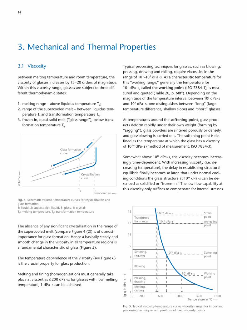
The absence of any significant crystallization in the range of the supercooled melt (compare Figure 4 (2)) is of utmost importance for glass formation. Hence a basically steady and smooth change in the viscosity in all tem perature regions is a fundamental characteristic of glass (Figure 5).
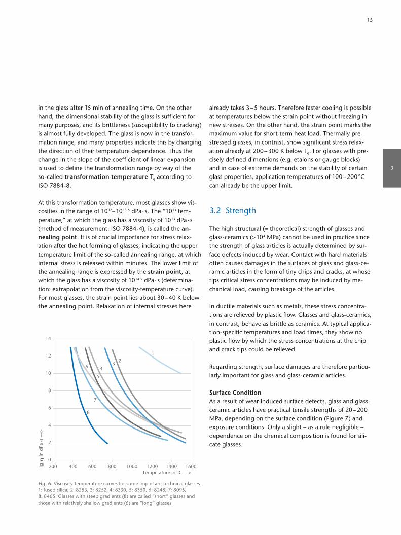
The temperature dependence of the viscosity (see Figure 6) is the crucial property for glass production.
Melting and fining (homogenization) must generally take place at viscosities ≤ 200 dPa · s; for glasses with low melting temperature, 1 dPa · s can be achieved.
Typical processing techniques for glasses, such as blowing, pressing, drawing and rolling, require viscosities in the range of 10 3–10 7 dPa · s. As a characteristic temperature for this “working range,” generally the temperature for 10 4 dPa · s, called the working point (ISO 78841), is measured and quoted (Table 20, p. 68ff). Depending on the magnitude of the temperature interval between 103 dPa · s and 10 7 dPa · s, one distinguishes between “long” (large temperature difference, shallow slope) and “short” glasses.
At temperatures around the softening point, glass products deform rapidly under their own weight (forming by “sagging”), glass powders are sintered porously or densely, and glassblowing is carried out. The softening point is defined as the temperature at which the glass has a viscosity of 10 7.6 dPa · s (method of measurement: ISO 78843).
Somewhat above 1010 dPa · s, the viscosity becomes increasingly timedependent. With increasing viscosity (i.e. decreasing temperature), the delay in establishing structural equilibria finally becomes so large that under normal cooling conditions the glass structure at 1013 dPa · s can be described as solidified or “frozenin.” The low flow capability at this viscosity only suffices to compensate for internal stresses
3. Mechanical and Thermal Properties
lg η
in d
Pa·s
––>
Temperature in °C ––>0 200 600 1000 1400
1
5
3
9
7
13
11
15
1800
1013 dPa · s
1014.5 dPa · s
107.6 dPa · s
104 dPa · s
Transforma-tion range
Blowing
Pressing,drawing
Melting,casting
Strainpoint
Annealingpoint
Softeningpoint
Workingpoint
Sintering,sagging
Fig. 5. Typical viscositytemperature curve; viscosity ranges for important processing techniques and positions of fixed viscosity points
14
already takes 3 – 5 hours. Therefore faster cooling is possible at temperatures below the strain point without freezing in new stresses. On the other hand, the strain point marks the maximum value for shortterm heat load. Thermally prestressed glasses, in contrast, show significant stress relaxation already at 200 – 300 K below Tg. For glasses with precisely defined dimensions (e.g. etalons or gauge blocks) and in case of extreme demands on the stability of certain glass properties, application temperatures of 100 – 200 °C can already be the upper limit.
3.2 Strength
The high structural (= theoretical) strength of glasses and glassceramics (> 104 MPa) cannot be used in practice since the strength of glass articles is actually determined by surface defects induced by wear. Contact with hard materials often causes damages in the surfaces of glass and glassceramic articles in the form of tiny chips and cracks, at whose tips critical stress concentrations may be induced by mechanical load, causing breakage of the articles.
In ductile materials such as metals, these stress concentrations are relieved by plastic flow. Glasses and glassceramics, in contrast, behave as brittle as ceramics. At typical applicationspecific temperatures and load times, they show no plastic flow by which the stress concentrations at the chip and crack tips could be relieved.
Regarding strength, surface damages are therefore particularly important for glass and glassceramic articles.
Surface ConditionAs a result of wearinduced surface defects, glass and glass ceramic articles have practical tensile strengths of 20 – 200 MPa, depending on the surface condition (Figure 7) and exposure conditions. Only a slight – as a rule negligible – dependence on the chemical composition is found for silicate glasses.
in the glass after 15 min of annealing time. On the other hand, the dimensional stability of the glass is sufficient for many purposes, and its brittleness (susceptibility to cracking) is almost fully developed. The glass is now in the transformation range, and many properties indicate this by changing the direction of their temperature dependence. Thus the change in the slope of the coefficient of linear expansion is used to define the transformation range by way of the socalled transformation temperature Tg according to ISO 78848.
At this transformation temperature, most glasses show viscosities in the range of 10 12 – 10 13.5 dPa · s. The “10 13 temperature,” at which the glass has a viscosity of 10 13 dPa · s (method of measurement: ISO 78844), is called the an-nealing point. It is of crucial importance for stress relaxation after the hot forming of glasses, indicating the upper temperature limit of the socalled annealing range, at which internal stress is released within minutes. The lower limit of the annealing range is expressed by the strain point, at which the glass has a viscosity of 10 14.5 dPa · s (determination: extrapolation from the viscositytemperature curve). For most glasses, the strain point lies about 30 – 40 K below the annealing point. Relaxation of internal stresses here
lg η
in d
Pa·s
––>
Temperature in °C ––>200 400 800600 1000 1200 1400 16000
4
2
8
6
12
10
14
12
346
8
5
7
Fig. 6. Viscositytemperature curves for some important technical glasses. 1: fused silica, 2: 8253, 3: 8252, 4: 8330, 5: 8350, 6: 8248, 7: 8095, 8: 8465. Glasses with steep gradients (8) are called “short” glasses and those with relatively shallow gradients (6) are “long” glasses
3
15

Size dependenceIncreasing the stressed area increases the probability of low strength flaws within this area. This relationship is important for converting of experimental strengths, which are mostly determined using small test specimens, to large glass articles such as pipelines, where many square meters of glass may be loaded (Figure 10).
StrengtheningThe defects that reduce the strength of the surfaces become ineffective if the glass surface ist subjected to compressive stress. The resulting strength of a glass article may be so high that it virtually sets no limits to technical applications. In glass articles with simple geometries, for example flat glass, the entire surface of the article can be put under compressive stress.
The toughening can be caused by rapid cooling (quenching) of the softened glass (Figure 11) or, in suitable glasses, by an ion exchange in an approximately 50 – 200 μm thick surface layer. In subsequent external loading (tensile or bending), the externally induced stress adds to the internal stress. Up to the value of the compressive surface stress,
Time and size dependenceFor testing and applying tensile strength values, the time dependence of the load and the size of the surface area exposed to the stress are particulary important.
As a result of subcritical crack growth due to stress corrosion, a long lasting tensile stress may boost critical surface flaws, thus reducing the residual strength with time. Hence the strength of glass and glassceramics is timedependent!
Stress corrosion causes the dependence of the measured fracture probability on the stress rate as depicted in Figure 8.
Static fatiqueFracture analyses of broken specimens for the initial flaw, its origin and growth kinetics yield further information about the time dependence of the strength of glasses and glassceramics. Some rules are established for estimating the strength for a permanent load from fast tests with a constant load rate, see Figure 9 for example. As a simple rule, the permanent strength (for years of loading) will only amount to about 1/2 to 1/3 of the strength measured in fast experiments.
σE in MPa ––>300200100705030201075
A3
80
605040
20
10
64
2
1
95
99
small
F in
% –
–>
grain size
large without deliberate damage
B
A: nominal strength values for chem. techn. largescale units B: … and for normal glass constructions
Fig. 7. Failure probability F for samples abraded by various size grains; predamaged surface area: 100 mm2, rate of stress increase σ̇ = 10 MPa/s
σE in MPa ––>3002001007050302010753
80
605040
20
10
64
2
1
95
99
F in
% –
–>
chem.-techn.large-scaleunits
σ = 0,01 .
0,1 1 10 100 1000 MPa/snominal strengthvalues for
normalglassconstruc-tions
Fig. 8. Failure probability F of a predamaged surface for various rates of stress increase σ̇. (predamaged area: 100 mm2, grain size: 600)
16

perature (section A), the curve shows a distinct bend and then gradually increases up to the beginning of the experimentally detectable plastic behavior (section B = quasilinear region). A distinct bend in the extension curve characterizes the transition from the predominantly elastic to the more visco elastic behavior of the glass (section C = transformation range). As a result of increasing structural mobility, the temperature dependencies of almost all glass properties are distinctly changed. This transformation range is characterized by the transformation temperature Tg according to ISO 78848. Figure 13 shows the linear thermal expansion curves of five glasses; 8330 and 4210 roughly define the normal range of technical glasses, with expansion coefficients α(20 °C; 300 °C) = 3.3 – 12 x 10–6/K. The linear thermal expansion is an essential variable for the sealability of glasses with other materials and for thermally induced stress formation, and is therefore of prime importance for glass applications.
a superimposed tensile stress keeps the surface under total compressive load. Thus, surface condition, loading rate, and loading time do not influence the strength.
3.3 Elasticity
The ideal brittleness of glasses and glassceramics is matched by an equally ideal elastic behavior up to the breaking point. The elastic moduli for most technical glasses is within the range of 50 – 90 GPa. The mean value of 70 GPa is about equal to Young’s modulus of aluminum. Poisson’s ratio of most glasses is in the range 0.21 to 0.25 and is lower than for metals or plastics.
3.4 Coefficient of linear thermal expansion
With few exceptions, the length and the volume of glasses increase with increasing temperature (positive coefficient).
The typical curve begins with a zero gradient at absolute zero (Figure 12) and increases slowly. At about room tem
σD in
MPa
––>
σE in MPa ––>
20
0
40
60
80
100
0 20 40 60 80 100 120 140
102 s (1.7 min)
105 s (1.2 days)
108 s (3.17 years)
1011 s (3170 years)
Lifetime:
Fig. 9. Timerelated strength σD (strength under constant loading) compared to experimental strength σ̇E at 10 MPa/s stress increase with lifetime tL, in normally humid atmosphere (sodalime glass).
σE in MPa ––>3002001007050302010753
80
605040
20
10
64
2
1
95
99
F in
% –
–>
chem.-techn.large-scaleunits
nominal strengthvalues for
S = 10000 1000 100 10 mm2
normalglassconstruc-tions
Fig. 10. Failure probability F for differently sized stressed areas S; all samples abraded with 600 mesh grit, stress rate σ̇ = 10 MPa/s
3
17

In addition to the geometric factors (shape and wall thickness), the material properties α, E and µ decisively influence the thermal strength of glasses subjected to temperature variations and/or thermal shock. Thermal loads of similar articles made from different glasses are easily compared by means of the characteristic material value
φ = σ ΔT
= α E1 – µ
[MPaK–1],
which indicates the maximum thermally induced stress to be expected in a flexresistant piece of glass for a local temperature difference of 1 K. Because cracking originates almost exclusively from the glass surface and is caused there by tensile stress alone, cooling processes are usually much more critical than the continuous rapid heating of glass articles.
SealabilityIn fusion sealing with other materials, the decisive glass property is the linear contraction. As Figure 14 shows, the experimental setting point TE lies in the already sharply bent section of the glass curve, and the experimental setting temperature increases with increasing cooling rate. Predicting the linear contraction is only possible if the shape of the glass curve and the setting point TE for the respective cooling rate are known. The stressoptical measurement of stresses in test fusions with practiceoriented cooling rates (ISO 4790) is a simpler and much more accurate method of testing the sealability.
Thermal stressesOwing to the low thermal conductivity of glass (typically 0.9 – 1.2 W/(m · K) at 90 °C, or a minimum of 0.6 W/(m · K) for highleadcontaining glasses), temperature changes produce relatively high temperature differences ΔT between the surface and the interior, which, depending on the elastic properties E (Young’s modulus) and µ (Poisson’s ratio), and on the coefficient of linear thermal expansion α, can result in stresses
σ = ΔT α E (1 – µ)
[MPa].
Compressivestress
Tensilestress
a
0
M M
b
c
x x
x
100 100 MPa200300
Fig. 11. Stress distribution across the thickness of thermally prestressed flat glass (a) without, (b) with additional bending M; (c) stress distribution in bending without prestressing
Rela
tive
cont
ract
ion Δ
I/I –
–>
Temperature in K ––>10000 200 400 600 800
CBA
Tg
Fig. 12. Typical thermal expansion – temperature curve for glasses
18

Rela
tive
cont
ract
ion
ΔI/I
––>
Temperature in °C ––>0 TE
Metal
Glass
Fig. 14. Contraction/expansion curves of two fusion partners which are shifted so that they intersect at setting temperature TE. The vertical difference thus describes the contraction difference with the correct sign.
ΔI/I
∙ 10
5 ––
>
Temperature in °C ––>
100
0
200
300
400
500
600
700
0 100 200 300 400 500 600 700
4210
8095
8250
8330
Fused silica
Fig. 13. Linear thermal expansion of various technical glasses and of fused silica
PYRAN® Platinum firerated glassceramic resists fire without fracturing.
3
19

As electrically highly insulating materials, glasses are used in electrical engineering and electronics for the production of highvacuum tubes, lamps, electrode seals, hermetically encapsulated components, highvoltage insulators, etc. Moreover, glasses may be used as insulating substrates of electrically conducting surface layers (surface heating elements and data displays).
4.1 Volume resistivity
Electrical conductivity in technical silicate glasses is, in general, a result of the migration of ions – mostly alkali ions. At room temperature, the mobility of these ions is usually
so small that the volume resistivities with values above 1015 Ω cm (1013 Ω m) are beyond the range of measurement. The ion mobility increases with increasing temperature. Besides the number and nature of the charge carriers, structural effects of other components also influence the volume resistivity and its temperature relationship. An Arrhenius law which is used in glass science sometimes also called RaschHinrichsen law applies to this relationship at temperatures below the transformation range:
lg ρ = A – B/T
ρ = electrical volume resistivityA, B = specific glass constantsT = absolute temperature
4. Electrical Properties
For more than 70 years, SCHOTT has been developing vacuumtight assemblies of glass and metal that enable electrical signals to pass through the walls of hermetically sealed packages, relays, for example.
20
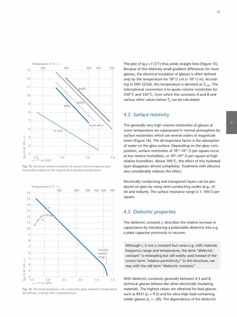
The plot of lg ρ = f (1/T) thus yields straight lines (Figure 15). Because of the relatively small gradient differences for most glasses, the electrical insulation of glasses is often defined only by the temperature for 108 Ω cm (= 106 Ω m). According to DIN 52326, this temperature is denoted as Tk100. The international convention is to quote volume resistivities for 250 °C and 350 °C, from which the constants A and B and various other values below Tg can be calculated.
4.2 Surface resistivity
The generally very high volume resistivities of glasses at room temperature are superposed in normal atmosphere by surface resistivities which are several orders of magnitude lower (Figure 16). The allimportant factor is the adsorption of water on the glass surface. Depending on the glass composition, surface resistivities of 1013– 1015 Ω per square occur at low relative humidities, or 108– 1010 Ω per square at high relative humidities. Above 100 °C, the effect of this hydrated layer disappears almost completely. Treatment with silicones also considerably reduces this effect.
Electrically conducting and transparent layers can be produced on glass by using semiconducting oxides (e.g., of tin and indium). The surface resistance range is 1 – 100 Ω per square.
4.3 Dielectric properties
The dielectric constant εr describes the relative increase in capacitance by introducing a polarizable dielectric into e.g a plate capacitor previously in vacuum.
Although εr is not a constant but varies e.g. with material, frequency range and temperature, the term “dielectric constant” is misleading but still widely used instead of the correct term “relative permittivity.” In this brochure, we stay with the old term “dielectric constant.”
With dielectric constants generally between 4.5 and 8, technical glasses behave like other electrically insulating materials. The highest values are obtained for lead glasses such as 8531 (εr = 9.5) and for ultrahigh leadcontaining solder glasses (εr = ~20). The dependence of the dielectric
lg ρ
in Ω
⋅ cm
––>
<–– T–1 in 103K–1
Temperature in °C ––>
4
3
5
6
7
8
9
10
11
12
13
2.5 2.0
200 300 400 500 700
1.5 1.0
80958250
Fused silica
N 16 B
8409
Fig. 15. Electrical volume resistivity of various technical glasses and fused silica related to the reciprocal of absolute temperature
lg ρ
in Ω
⋅ cm
––>
<–– T–1 in 103K–1
Temperature in °C ––>
4
3
2
5
6
7
8
9
10
11
12
13
14
15
16
b
a
3.03.5 2.5 2.0
200100 300 400 500 700
1.5 1.0
Transfor-mationrange
Fig. 16. Electrical resistance r of a sodalime glass related to temperature (a) without, and (b) with a hydrated layer
4
21

constants εr on frequency and temperature is relatively small (Figure 17). For a frequency range of 50 – 109 Hz, εr values will generally not vary by more than 10 %.
Reversing the polarity and shifting the dipoles of a dielectric situated in an alternating electrical field will cause heating and hence dissipation of energy as compared to ideal lossfree reactive power. The ratio of practical performance to ideal lossfree performance, which is dependent on the type of material as well as on frequency and temperature, is called the dielectric dissipation factor tanδ.
Due to the diverse mechanisms which cause such losses in glasses, there is a strong relationship with frequency, which shows minimum tanδ values in the region of 106– 108 Hz and increasing values for lower and higher frequencies (Figure 18).
At 106 Hz, the dissipation factor tanδ for different glasses lies between 10–2 – 10–3; fused silica, with 10–5, has the lowest dissipation factor of all glasses. The special glass 8248 has relatively low losses and tanδ increases only slightly up to 5.5 GHz (tanδ = 3 x 10⁻³).
tan δ
in a
.u. –
–>
lgf in Hz ––>0 2 4 6 8 10 12 14
2
1
3
4
Fig. 18. Schematic representation of the frequency spectrum of dielectric losses in glass at room temperature (Stevels). The solid curve shows the total losses builtup from: 1. conduction losses, 2. relaxation losses, 3. vibration losses, and 4. deformation losses.
tan δ
––>
Temperature in °C ––>
10–2
10–3
10–1
–100 0 100 200
8095
8487
8330
N 16 B
8245
8486
Fig. 19. Dissipation factor tanδ as a function of temperature in the range –100 to +200 °C, measured at 1 MHz
Die
lect
ric c
onst
ant ε r
––>
Temperature in °C ––>
5
4
7
6
–100 0 100 200
8095
8245
8486
8487
8330
Fig. 17. Dielectric constant εr of electrotechnical glasses related to temperature, measured at 1 MHz
22
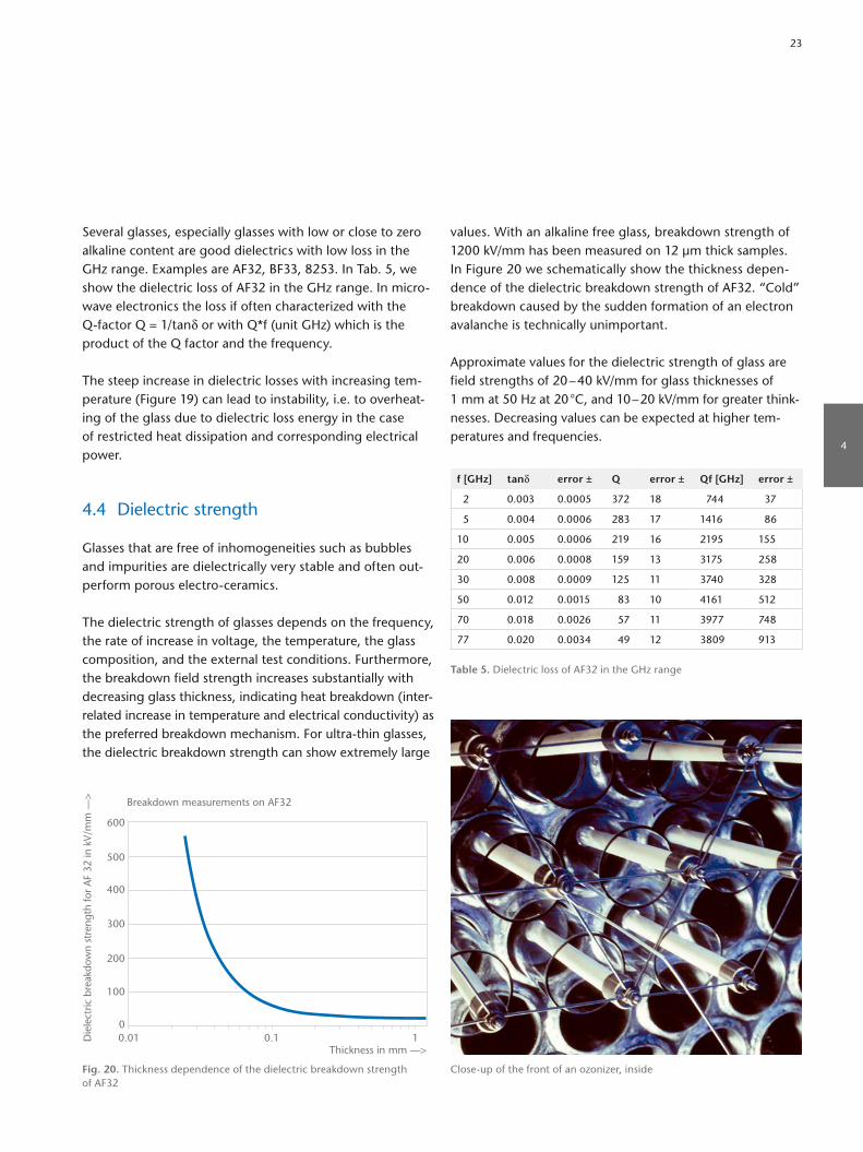
values. With an alkaline free glass, breakdown strength of 1200 kV/mm has been measured on 12 µm thick samples. In Figure 20 we schematically show the thickness dependence of the dielectric breakdown strength of AF32. “Cold” breakdown caused by the sudden formation of an electron avalanche is technically unimportant.
Approximate values for the dielectric strength of glass are field strengths of 20 – 40 kV/mm for glass thicknesses of 1 mm at 50 Hz at 20 °C, and 10 – 20 kV/mm for greater thinknesses. Decreasing values can be expected at higher temperatures and frequencies.
f [GHz] tanδ error ± Q error ± Qf [GHz] error ±
2 0.003 0.0005 372 18 744 37
5 0.004 0.0006 283 17 1416 86
10 0.005 0.0006 219 16 2195 155
20 0.006 0.0008 159 13 3175 258
30 0.008 0.0009 125 11 3740 328
50 0.012 0.0015 83 10 4161 512
70 0.018 0.0026 57 11 3977 748
77 0.020 0.0034 49 12 3809 913
Table 5. Dielectric loss of AF32 in the GHz range
Several glasses, especially glasses with low or close to zero alkaline content are good dielectrics with low loss in the GHz range. Examples are AF32, BF33, 8253. In Tab. 5, we show the dielectric loss of AF32 in the GHz range. In microwave electronics the loss if often characterized with the Qfactor Q = 1/tanδ or with Q*f (unit GHz) which is the product of the Q factor and the frequency.
The steep increase in dielectric losses with increasing temperature (Figure 19) can lead to instability, i.e. to overheating of the glass due to dielectric loss energy in the case of restricted heat dissipation and corresponding electrical power.
4.4 Dielectric strength
Glasses that are free of inhomogeneities such as bubbles and impurities are dielectrically very stable and often outperform porous electroceramics.
The dielectric strength of glasses depends on the frequency, the rate of increase in voltage, the temperature, the glass composition, and the external test conditions. Furthermore, the breakdown field strength increases substantially with decreasing glass thickness, indicating heat breakdown (interrelated increase in temperature and electrical conductivity) as the preferred breakdown mechanism. For ultrathin glasses, the dielectric breakdown strength can show extremely large
Closeup of the front of an ozonizer, inside
Die
lect
ric b
reak
dow
n st
reng
th fo
r A
F 32
in k
V/m
m –
–>
Thickness in mm ––>0.01 10.10
100
200
300
400
500
600
Breakdown measurements on AF32
Fig. 20. Thickness dependence of the dielectric breakdown strength of AF32
4
23

5. Optical Properties
5.1 Refraction of light
The ratio of the speed of light in vacuum to that in a defined material is called the refractive index nλ of that material. The refractive index of glass is dependent on the wavelength (dispersion). This is a decisive factor in purely optical applications.
The refractive indices nd of technical glasses are valid for λd = 587.6 nm and generally lie within the range of 1.47 – 1.57. Exceptions to this rule are lead glasses with PbO contents of over 35 % (glass type 8531 : nd = 1.7). The principal dispersion nF – nc (λF = 486.1 nm, λc = 656.3 nm) of technical glasses lies between 0.007 bis 0.013.
5.2 Reflection of light
At the boundary glass surface – air, the incident light is partly reflected. At perpendicular incidence, the reflectance R(λ) at wavelength λ is expressed as follows
R(λ) = ( n(λ) – 1n(λ) + 1 )2
For technical glasses R(λ = 587.6 nm) = Rd lies within 3.6 % to 4.9 % per interface.
The transmittance τd and the reflectance ρd of a nonabsorbing planeparallel glass plate with two glassair surfaces, with multiple reflections taken into account, are expressed as follows
τd = (1 – Rd)2
1 – Rd2
= 1 – Rd
1 + Rd
= 2nd
nd2 + 1
and
ρd = 2Rd
1 + Rd
= (nd – 1)2
nd2 + 1
.
High homogeneity glass
24

The transmittance τd at perpendicular incidence decreases correspondingly to values between 93.1 % and 90.6 %.
The reflection rd of a parallel glass plate can be reduced (and its total transmittance τd can be increased) by using socalled antireflective (AR) coatings. In its simplest form, a transparent layer on each surface with nlayer = √—nglass and a thickness of λ/4/nlayer will reduce the reflection for perpendicular incidence and wavelength λ completely. For other wavelengths close to λ, the reflection is reduced but not canceled. With more complex multylayer AR coatings, reflections in the visible range can be reduced to less than 1 % per surface.
5.3 Transmittance
Normally, glass is transparent to visible light and certain regions of UV and IR radiation. Losses in transmittance occur due to internal absorption and reflection, as indicated above. The socalled internal transmittance τi can be modified by using coloring agents (oxides of transition elements or colloids) or fine particles in the glass, which have different refractive indices (light scattering).
The internal transmittance τi of an absorbing glass is a function of the thickness d: τi = e–αd, where α is the spectral absorption coefficient.
The relation between spectral transmittance τ and spectral internal transmittance τi is:
τ(λ) = ( 2n(λ)n(λ)2 + 1) τi(λ)
The dependence of the factor ( 2n(λ)n(λ)2 + 1)
on wavelength is usually small, thus, a constant reflection factor P
Pd = 2nd
nd2 + 1
is sufficient for use in most cases.
The best UV transmission is achieved with pure fused silica (UV cutoff for 1 mm thickness is in the region of 160 – 180 nm); particularly good UVtransmitting multi component glasses have cutoffs of up to 220 nm wavelength (Figure 21); normal technical glasses (Figure 22) already absorb considerably at 300 nm.
Tran
smis
sion
in %
––>
Wavelength in nm ––>200 250 300 350 4000
20
40
60
80
100
8405
8337B
Fig. 21. UV transmission of highly UVtransparent technical glass types 8337B and 8405 at 0.5 mm glass thickness
Tran
smis
sion
in %
––>
Wavelength in nm ––>200 500 20001000 5000 100000
20
10
40
30
60
80
100
90
70
50
2 mm
1 mm
8 mm
Fig. 22. Transmission of DURAN® 8330 for thicknesses 1, 2 and 8 mm
5
25

As an alternative to bulk filter glasses, coated interference filters are used. Here a transparent glass substrate is coated with a set of thin transparent layers of e.g. oxidic materials with different refractive indices. The spectral properties of these filters are defined by interference effects.
Optical filter glass and inteference filters are optimized for industrial applications, thus the main focus is the repro-ducibility of spectral transmittance. However, these glasses appear to be colored if their filter effect lies within the visi-ble light spectrum.
Chalcogenide glassIn most known glass types, oxides of e.g. silicon, phospho-rous, lanthanum and borate are building the glass forming network. Though some oxidic glass types with special com-positions melted under very dry conditions show transmit-tance until 4 – 5 microns, the absorption of the cation-O-bond in the network sets a limit to the (mid – far) infrared (IR) transmission of these glasses. The main characteristic of chalcogenide glasses is the complete replacement of the element oxygen by other elements of the chalcogenide group like sulfur, selenium or tellurium to extend transmit-tance further into the mid to far IR. For instance, SCHOTT IR chalcogenide glasses (IRG) exhibit high transmission from the visible range to beyond 12 µm into the far infrared (see. Figure 24).
Optical glassThe term “optical glass” is used in distinction to “technical glass” for a specific group of glasses mainly for optical applications like imaging in the UV, visible, and infrared wavelength range. These applications require a broad set of glasses with high transmission and well defined refrac-tive index and specific dispersion properties (described by Abbe-numbers). Combinations of these glasses allow for the construction of high-performance optical systems.
Up to 17 or more different raw materials with the lowest level of impurities to avoid absorption by coloring elements are used to achieve the desired specifications. Each optical glass is described (beside others) by its coordinates in the so-called “Abbe-Diagram” (see Figure 23).
Optical filter glassOptical filter glass is known for its selective absorption in certain wavelength ranges. The absorption within the glasses is caused either by ions of heavy metals or of rare earths or it is caused by nano crystals within the glass matrix. By com-bining different coloring agents a wide range of different filter functions (neutral density filters, longpass filters, short pass filters and bandpass filters) can be obtained. Figure 25 depicts special UV bandpass filters that have a region of high internal transmittance in the UV and high absorption for visible light.
Thickness 10.0 mm (Typical Values)Transmission of IRG 22–2680
70
60
50
40
30
20
10
0
Tran
smis
sion
in %
––>
0 2000 4000 6000 8000 10000 12000 14000 16000 18000
Wavelength in nm ––>
IRG 22 IRG 23 IRG 24 IRG 25 IRG 26
Fig. 24. Transmission of IRG 22 – 26
Abbe-Diagram nd –νd
Description of Symbols
Lead and arsenic free N- or P-glass
Classical crown and flint glass
Glass available as N-glass or classical flint glass
Glass suitable for precision molding
HT – High transmittance glass
HTultra – Ultra high transmittance glass
* Available in step 0.5
PSK
FK
PK
LAK
BK K
SK
LLF
BALF
BAFSSK
BASF
F
SF
LASF
LF
LAF
KF
BAK4
452
824
16
11
145 57
57Q1 4
5
95
3
7
ZK7
KZFS2*
2
101052 A
1
51
2
64
KZFS11*
10
5
2
7
33
66
67
57
6
1156A
14
10
158
1
4
4041
31A
4743
21
235
34
108
34
14
12
227
21
5
5
1
69
37
51 50
58A
60
35
68
33B33A
35
9
45
46A 46B
*
9*
44*
KZFS8*
KZFS5* 2*
5*
KZFS4*
2*53A*
51*
5*51A*
7*
85 80 75 70 65 60 55 50 45 40 35 30 25 209095
1.45
1.50
1.55
1.60
1.65
1.70
1.75
1.80
1.85
1.90
1.95
2.00
2.05
nd
85 80 75 70 65 60 55 50 45 40 35 30 25 209095
1.45
1.50
1.55
1.60
1.65
1.70
1.75
1.80
1.85
1.90
1.95
2.00 nd
2.05
Janu
ary
2014
νd
νd
Fig. 23. SCHOTT Advanced Optics Abbe-Diagram that gives an overview of SCHOTT’s optical glass types
26

0.99
0.98
0.96
0.90
0.70
0.500.30
0.10
0.01
1E-04
200 300 400 500 600 700 800 900 1000 1100 1200Wavelength in nm ––>
Inte
rnal
tra
nsm
ittan
ce –
–>
UG11UG5 UG1
Fig. 25. UV bandpass filter for a glass thickness of 1 mm
nents. This path difference can either be estimated by means of the birefringence colors or measured with compensators:
Δs = K ∙ d ∙ Δσ [nm].
K is the stressoptical coefficient of the glass (determination according to DIN 52314).
K = Δsd
1Δσ
[MPa1]
Many glasses have stressoptical coefficients of about 3 x 10⁻⁶ MPa–1, and borosilicate glasses of up to 4 x 10⁻⁶ MPa–1. Highlead content glasses can have values down to nil or even negative.
Stressoptical measurements permit the determination of permanent stress in glass (state of annealing) as well as of reactive stress caused as a reaction to exterior forces. Stress optical measurements for the evaluation of glass seals with other glasses, metals, or ceramics are of particular importance. These offer a sensitive method of deter mining thermal expansion and contraction differences.
5.4 Color of glass
Color is a sensation perceived by the human eye whenobserving an illuminated filter glass or incandescent object.The color of glass is a function of its spectral transmission and the spectral energy distribution of the illuminating light source. Color stimulus is measurable and is defined by three numerical values (X, Y, Z) in accordance with color metric conventions set forth by the CIE (see publication CIE N° 15.2 (1986)). The first value is its brightness (standard tristimulus value) Y and the other two values define the color locus. There are two possibilities to define the color locus F (see Figure 26): Either the chromaticity coordinates x and y, or the dominant wavelength λd (at S) and the excitation purity Pe = DF : DS.
5.5 Stress birefringence
Owing to its very structure, glass is an isotropic material. Mechanical stress causes anisotropy which manifests itself as stressinduced birefringence. A ray of light impinging on glass will be resolved into two components vibrating in planes perpendicular to each other and having different phase velocities. After passing through a plate of thickness d which is subjected to a principal stress difference Δσ, an optical path difference Δs exists between the two compo
1.0
0.9
0.8
0.7
0.6
0.5
0.4
0.3
0.2
0.1
00.1 0.2 0.3 0.4 0.5 0.6 0.7 0.8 0.9 1.0
y
x
510 540
520
500
560
580
490
480
400
700
600620
F
S
D
Fig. 26. The color of optical filter glasses according to the definition of CIE 1931D: Color locus of the radiation source, for example D65S: Point at which the extension DF intersects the spectrum locus at λd
5
27

The chemically resistant glasses categorized as “borosilicate glasses” contain a high percentage of silica (70 – 80 %), considerable amounts of boric oxide (7 – 13 %), as well as alkali oxides (Na2O, K2O, 4 – 8 %), alumina (2 – 7 %), and sometimes alkaline earth oxides (CaO, BaO, 0 – 5 %). Characteristically, they have high chemical durability (hydrolytic class 1, acid class 1) and relatively low thermal expansion, giving high thermal resistance and enabling the manufacture of large, thickwalled components from these glasses.
These exceptional properties of borosilicate glasses were recognized by Otto Schott, and largescale melts were first put to use in 1892.
Chemically durable borosilicate glasses have such a high acid resistance that even for surface areas as large as 400 cm2, exposed to a sixhour boiling in 20 % hydrochloric acid, only very small weight losses can be measured. Because the measurement accuracy in determining the variation in the weight of glasses that have large surface areas is roughly equivalent with the weight losses themselves, a sound com
parison between the different glasses of this group is impossible. The values simply indicate high acid resistance.
On the other hand, silicate glasses with higher boric oxide contents (> 15 %) are generally not classified as chemically resistant. Examples are electrotechnical sealing glasses such as 8245 or 8250, which fall into acid class 4 and 3, respectively.
6.1 DURAN®
The coefficient of linear thermal expansion of 3.3 x 10⁻⁶/K is the lowest of all the largescale massproduced technical glasses with high chemical resistance. The low specific thermal stress φ = 0.24 N/(mm2 K) indicates its exceptional resistance to thermal shock and temperature variations. These properties allow the production and hot forming of large, thickwalled articles which can be exposed to application temperatures of up to max. 200 °C.
6. Highly Resistant Glasses for Laboratory, Pharma and ...
DURAN® tubing for a wide range of applications
28

tions. Their manufacturing, exclusively in the form of tubes, is today possible with exceptionally tight diameter and wall thickness tolerances. Therefore, the production of syringes, ampoules and vials and their filling on the highspeed filling lines of the pharmaceutical industry are unproblematic. Because the wall thickness of the tubes is comparatively small,
Its thermal properties coupled with outstanding water and acid resistance make DURAN® a highly suitable material for use in laboratories and largescale chemical plants, for example as pipelines, reaction vessels, heat exchangers, and so on.
For thinwalled DURAN® items, application temperatures can lie considerably above 200 °C. To guarantee shape stability, a maximum of 500 °C should not be exceeded.
DURAN® is made into tubes of up to 450 mm in dia meter and pressed and blown glassware. Processed as flat glass, it is available as a floated product under the tradename BOROFLOAT® 33 and as a rolled sheet glass under the tradename SUPREMAX® for applications in home appliances, lighting, chemical engineering, safety, optics, precision engineering and photovoltaics. Figures 27 and 28 illustrate the chemical resistance.
DURAN® is also available in different shapes and called CONTURAX®.
6.2 FIOLAX®
These highly resistant borosilicate glasses are particularly suited for pharmaceutical parenteral packaging such as syringes, ampoules and vials for highgrade injection solu
Att
acke
d la
yer
in µ
m –
–>
Temperature in °C ––>
0.01
0.001
0.1
1
0 50 150100
Na2O
SiO2
c (HCI) = 6 mol/lExposure time: 16 h
Fig. 27. Acid attack on DURAN®/BOROFLOAT® 33/SUPREMAX® 8330 as a function of temperature and calculated from leached amounts of Na2O and SiO2
Att
acke
d la
yer
in µ
m –
–>
Temperature in °C ––>
0.5
0
1.0
1.5
0 20 10040 60 80
c (NaOH) = 1 mol/lExposure time: 1 h
Fig. 28. Alkali attack on DURAN®/BOROFLOAT® 33/SUPREMAX® 8330 as a function of temperature and calculated from the weight losses
CONTURAX® Pro profile glass tubing
6
29
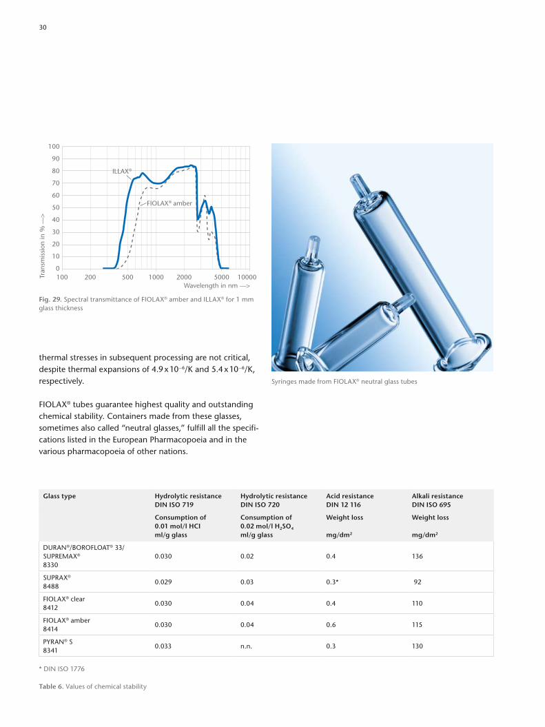
thermal stresses in subsequent processing are not critical, despite thermal expansions of 4.9 x 10⁻⁶/K and 5.4 x 10⁻⁶/K, respectively.
FIOLAX® tubes guarantee highest quality and outstanding chemical stability. Containers made from these glasses, sometimes also called “neutral glasses,” fulfill all the specifications listed in the European Pharmacopoeia and in the various pharmacopoeia of other nations.
Glass type Hydrolytic resistance DIN ISO 719
Hydrolytic resistance DIN ISO 720
Acid resistance DIN 12 116
Alkali resistance DIN ISO 695
Consumption of 0.01 mol/l HCI ml/g glass
Consumption of 0.02 mol/l H2SO4 ml/g glass
Weight loss mg/dm2
Weight loss mg/dm2
DURAN®/BOROFLOAT® 33/ SUPREMAX® 8330
0.030 0.02 0.4 136
SUPRAX®
84880.029 0.03 0.3* 92
FIOLAX® clear8412
0.030 0.04 0.4 110
FIOLAX® amber8414
0.030 0.04 0.6 115
PYRAN® S8341
0.033 n.n. 0.3 130
* DIN ISO 1776
Table 6. Values of chemical stability
Tran
smis
sion
in %
––>
Wavelength in nm ––>100 200 500 1000 2000 5000 100000
20
10
40
30
60
80
100
90
70
50FIOLAX® amber
ILLAX®
Fig. 29. Spectral transmittance of FIOLAX® amber and ILLAX® for 1 mm glass thickness
Syringes made from FIOLAX® neutral glass tubes
30

6.3 BOROFLOAT® 33/SUPREMAX®
BOROFLOAT® 33 is a highquality borosilicate glass with impressive properties that make it suitable for a wide range of applications. BOROFLOAT® 33 is manufactured using the microfloat process. SUPREMAX® is a rolled borosilicate glass that utilizes SCHOTT’s unique rolled sheet glass technology to offer thicknesses that cannot be produced via the microfloat process.
The chemical composition of BOROFLOAT® 33/SUPREMAX® complies with the requirements for a typical borosilicate glass according to DIN ISO 3585 and EN 1748 Pt. 1 respectively. Like all borosilicate glasses, BOROFLOAT® 33/SUPREMAX® demonstrate high resistance to water, many alkalis and acids as well as organic substances. Its chemical resistance is superior to that of most metals, even during longterm use and at temperatures in excess of 100 °C (as used as sight glasses in the chemical industry). Exposure to water and acids only results in the leaching out of small amounts of ions from the glass (as used in medicine and analytical engineering).
BOROFLOAT® 33/SUPREMAX® are produced using only the finest natural raw materials and are therefore harmless to human beings and the environment in accordance with the requirements of the European guideline ROHS/2002/95. The glass can be recycled for further use.
FIOLAX® clear, 8412This glass belongs to the chemically resistant alkaline earth containing borosilicate glass type. Its water and acid resistance correspond to those of DURAN®, and its alkali resistance is even higher. Alkaline preparations up to pH values of 12 can be stored and autoclaved in FIOLAX® clear.
FIOLAX® amber, 8414Due to additions of iron and titanium oxides, this borosilicate glass exhibits high light absorption in the blue and UV spectral regions (see Figure 29). Sensitive pharmaceutical preparations can therefore be effectively protected from light in the critical wavelength region.
AR-GLAS®
ARGLAS® with a CTE of 9.1 x 10⁻⁶/K belongs to the socalled sodalime glass family. The hydrolytical resistance is lower compared to the neutral glasses FIOLAX® and DURAN® but the glass is still stable enough to be used as a packaging material for nonparental drugs i.e. pipets, vials for tablets, and test tubes. An advantage is good workability and the good price/performance ratio.
BOROFLOAT® 33 is a highly versatile hightech material suitable for manifold applications in industry, engineering and research
SUPREMAX® is available in a broad range of thicknesses
6
31
7. Flat Glasses for Home Appliances, Architecture and Safety
Amiran® antireflective glass
32
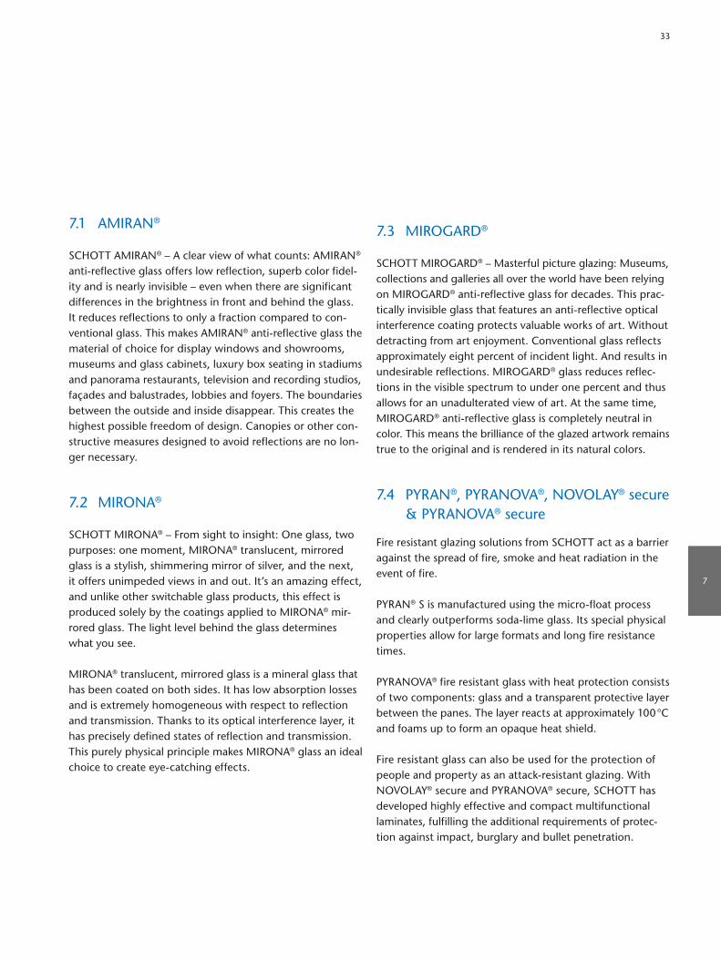
7.3 MIROGARD®
SCHOTT MIROGARD® – Masterful picture glazing: Museums, collections and galleries all over the world have been relying on MIROGARD® antireflective glass for decades. This practically invisible glass that features an antireflective optical interference coating protects valuable works of art. Without detracting from art enjoyment. Conventional glass reflects approximately eight percent of incident light. And results in undesirable reflections. MIROGARD® glass reduces reflections in the visible spectrum to under one percent and thus allows for an unadulterated view of art. At the same time, MIROGARD® antireflective glass is completely neutral in color. This means the brilliance of the glazed artwork remains true to the original and is rendered in its natural colors.
7.4 PYRAN®, PYRANOVA®, NOVOLAY® secure & PYRANOVA® secure
Fire resistant glazing solutions from SCHOTT act as a barrier against the spread of fire, smoke and heat radiation in the event of fire.
PYRAN® S is manufactured using the microfloat process and clearly outperforms sodalime glass. Its special physical properties allow for large formats and long fire resistance times.
PYRANOVA® fire resistant glass with heat protection consists of two components: glass and a transparent protective layer between the panes. The layer reacts at approximately 100 °C and foams up to form an opaque heat shield.
Fire resistant glass can also be used for the protection of people and property as an attackresistant glazing. With NOVOLAY® secure and PYRANOVA® secure, SCHOTT has developed highly effective and compact multifunctional laminates, fulfilling the additional requirements of protection against impact, burglary and bullet penetration.
7.1 AMIRAN®
SCHOTT AMIRAN® – A clear view of what counts: AMIRAN® antireflective glass offers low reflection, superb color fidelity and is nearly invisible – even when there are significant differences in the brightness in front and behind the glass. It reduces reflections to only a fraction compared to conventional glass. This makes AMIRAN® antireflective glass the material of choice for display windows and showrooms, museums and glass cabinets, luxury box seating in stadiums and panorama restaurants, television and recording studios, façades and balustrades, lobbies and foyers. The boundaries between the outside and inside disappear. This creates the highest possible freedom of design. Canopies or other constructive measures designed to avoid reflections are no longer necessary.
7.2 MIRONA®
SCHOTT MIRONA® – From sight to insight: One glass, two purposes: one moment, MIRONA® translucent, mirrored glass is a stylish, shimmering mirror of silver, and the next, it offers unimpeded views in and out. It’s an amazing effect, and unlike other switchable glass products, this effect is produced solely by the coatings applied to MIRONA® mirrored glass. The light level behind the glass determines what you see.
MIRONA® translucent, mirrored glass is a mineral glass that has been coated on both sides. It has low absorption losses and is extremely homogeneous with respect to reflection and transmission. Thanks to its optical interference layer, it has precisely defined states of reflection and transmission. This purely physical principle makes MIRONA® glass an ideal choice to create eyecatching effects.
7
33

SCHOTT® Hydro BarrierSCHOTT® Hydro Barrier is a transparent coating that repels liquids and stops liquids from passing over the edge of the glass, i.e. on a refrigerator shelf. It is extremely durable and withstands mechanical stress and temperatures up to 120 °C. SCHOTT® Hydro Barrier is an optically clear hydrophobic coating developed to protect glass. The thin coating (5–15 nanometers) is chemically bound to the substrate (glass) to create a durable protective seal.
Features of glass in combination with electronic components SCHOTT offers special printing technologies such as heating circuits and capacitive printing to integrate functionality into the glass.
Heating circuits are high current circuits which are printed onto the glass. It is a conductive layer which transmits and can be used to apply power circuits onto the glass.
Capacitive printing is used for electrical circuits to conduct electricity and can be used for touches on control panels. The conductive layer is printed on the rear side of the glass as an interface for capacitive switches to avoid the assembly of a capacitive foil.
In addition, SCHOTT offers the following features for glasses compatible with electronics: IR transparent printing which lets through infrared waves, haptic printing effect and dead front effect printing.
7.5 Processed flat glass for home appliances
SCHOTT® Flat Glass is a thermally toughened (tempered) float glass produced from a variety of raw materials. Due to its particular resistance to thermal shock, temperature gradients and mechanical loads (e.g. bending and impact), SCHOTT® Flat Glass is an ideal component in many applications such as home appliances and commercial refrigeration applications.
7.6 Special solutions for home appliances
Easy-to-clean coating SCHOTT® CleanPlusSCHOTT® CleanPlus is the industry leading easytoclean coating in the market for inner oven door glasses for baking ovens. The coating is resistant against high temperatures as well as mechanical and chemical stress. SCHOTT® CleanPlus is made of a fully tempered, heatreflective glass and an advanced, easytoclean surface. The powerful selfcleaning capability is based on a system that consists of inorganic and hybrid layers. This results in the combined advantages of the inorganic matrix and the functional organic components. Whereas the inorganic, glassy network delivers high mechanical stability, the organic components help make it easy to clean. This stateoftheart treatment repels spills and dirt away from the inner window surface, allowing it to be cleaned with minimum effort.
Conductive layer rearsideConductive layer front side
34

7.8 Radiation shielding glasses
RD 30 protective clear glass filters are used against Xscattered rays at mammography work stations. Therefore, the lead equivalent is 0.5 mm Pb. RD 30 can also be used for all other applications in the Xray area if 0.5 mm Pb is required. RD 30 is a drawn flat glass. The lead oxide content is more than 22 percent by weight. Therefore, a density of above 3.13 g/cm³ is reached, so that 6 mm glass thickness fulfill all legal safety regulations.
Radiation shielding glass RD 50® protects against Xrays and gamma rays in the medical and technical field. RD 50® is an extra dense flint glass. Its protective effect is based on its high content of heavy metallic oxides of nearly 70 percent by weight. The lead oxide content alone is more than 65 percent by weight. Therefore, a density of above 5.05 g/cm³ is reached, so that relatively small glass thicknesses fulfill all legal safety regulations. Radiation shielding glass RD 50® meets the requirements of DIN EN 613312.
Assembly solutionsSCHOTT offers a broad range of assembly solutions to the home appliance industry including encapsulation and a broad range of assembly solutions combining glass with plastics and metal parts (i.e. for refrigerator shelves, washing machine lids and doors). Solutions to combine glass with lighting are also available.
7.7 Insulated glass doors for commercial refrigeration
SCHOTT Termofrost® insulated glass door systems are used in a broad range of applications for commercial refrigeration to display and store chilled products down to +2 °C, and frozen goods down to –25 °C. The glass doors typically contain double or triple glazed insulated glass units, the front and rear panes are made of tempered safety glass. Selfclosing, condensationfree door systems are essential to display food and beverages at the right temperature, while incurring the lowest possible energy costs.
Refrigerator shelfFragmentation test for a tempered glass
SCHOTT radiation shielding glass offers various levels of protectionSCHOTT Termofrost® insulated glass door system
7
35

8.3 Thin glasses
Manufactured in proprietary downdraw and updraw processes, SCHOTT offers a choice of technical thin glasses with outstanding material properties and pristine surface qualities.
AF 32® eco is an alkalifree flat glass available in a thickness range from 0.03 mm to 1.1 mm. Its firepolished surface has a roughness value below 1 nm. The coefficient of thermal expansion of AF 32® eco matches silicon, therefore it is the perfect choice as optical packaging material in semiconductor related applications. Due to its high transformation temperature, it can be used for high temperature applications up to approx. 600 °C. AF 32® eco is supplied in wafer formats and is manufactured with ecofriendly refining agents.
D 263® T eco thin glass is a clear borosilicate glass that has high chemical resistance. It is available in a variety of thicknesses ranging from 0.03 mm to 1.1 mm. D 263® T eco borosilicate glass is available in standard stock size sheets or can be custom cut into round or square shapes. D 263® T eco thin glass is used as substrate glass for coatings in optical interference filters and in touch panel applications in the automotive and electronics industries. D 263® T eco is manufactured with ecofriendly refining agents.
MEMpax® is a borosilicate glass which has similar chemical and physical characteristics as the wellknown product SCHOTT Borofloat® 33.
At the same time, MEMpax® is produced as wafers in much lower thicknesses of 0.1 – 0.7 mm and offers thin wafers that no longer need to be ground and polished, thanks to its excellent surface quality.
The coefficient of linear thermal expansion of MEMpax® corresponds with that of silicon, therefore this glass is perfectly suited for use in anodic bonding.
Its low fluorescence, combined with its excellent surface quality, flatness and homogeneity, opens up numerous application possibilities for SCHOTT MEMpax® in MEMS and biotechnology.
8.1 BOROFLOAT® 33
BOROFLOAT® 33 is a premium quality, floated borosilicate glass from SCHOTT. It is recognized worldwide for its outstanding material properties and has become established as one of the key materials used in the electronics and semiconductor industry.
Thin BOROFLOAT® is the glass substrate of choice for a high number of technically challenging applications. With a premiumgrade surface quality, a very tight thickness tolerance, an extremely low level of defects and an outstanding level of transparency, BOROFLOAT®’s unique performance characteristics are often decisive in fulfilling the requirements of modern thin glass applications.
BOROFLOAT® 33’s coefficient of linear thermal expansion (CTE) matches perfectly with that of Silicon, making it the material of choice for anodic bonding and temporary bonding technologies.
8.2 Xensation® Cover
Xensation® Cover is a floated aluminosilicate glass that offers an outstanding level of mechanical impact and bending strength, as well as high resistance to scratches. This specialty glass has been designed for highly efficient chemical strengthening to achieve strength performance levels ideally suited for cover glass protecting touch screen devices, as well as protective and ruggedized lightweight glazing solutions.
The unique glass composition of Xensation® Cover results in the most robust and reliable cover glass available on the market today.
8. Thin Glasses/UltraThin Glasses for Electronics and More
Xensation® Cover: Aluminosilicate glass for capacitive touch technologies
36

Thanks to its low alkali content, MEMpax® acts as a high quality insulator. For this reason, MEMpax® is an extremely appropriate material for applications that require electrical insulation at high temperatures (up to 450 °C). It is manufactured with ecofriendly refining agents.
D 263® M is a colorless borosilicate glass for microscopy cover slip applications. It is available in different stock sheet sizes with thicknesses ranging from 0.1 mm to 0.21 mm. D 263® M is a perfect choice as cover glass for microscopic analysis and meets the requirements specified in ISO 82551 and DIN ISO 82551.
The chemical composition of D 263® M ensures valid and reliable research results due to its low fluorescence and high chemical resistance.
B 270i®, is an ultra white lowiron glass manufactured in an updraw process. It offers high stability with respect to solarization in combination with high transmission in the visible wavelength range. It has a firepolished surface and high chemical stability. B 270i® is available in a wide range of thicknesses and various instock formats. Customized formats (e.g. rounds) and processing can be offered upon request.
Ultra-thin glass – the flexibility of the downdraw process technology in terms of thicknesses has recently introduced the possibility to manufacture ultrathin glass in the range of 100 down to 25 µm from some of the well established glass types mentioned above. Glass of that thickness can be rolled up on a core similar to polymer film.
Inspection Bead cuttingRolling
Packaging
Defect mapping
Glass on roll or cut-to-size sheets
Down-draw
Roller
Glass ribbon
Roller
Annealingfurnace
Molten glass
Ultrathin glass on roll
Fig. 30. Schematic representation of the production up to the finalized sheet
8
37
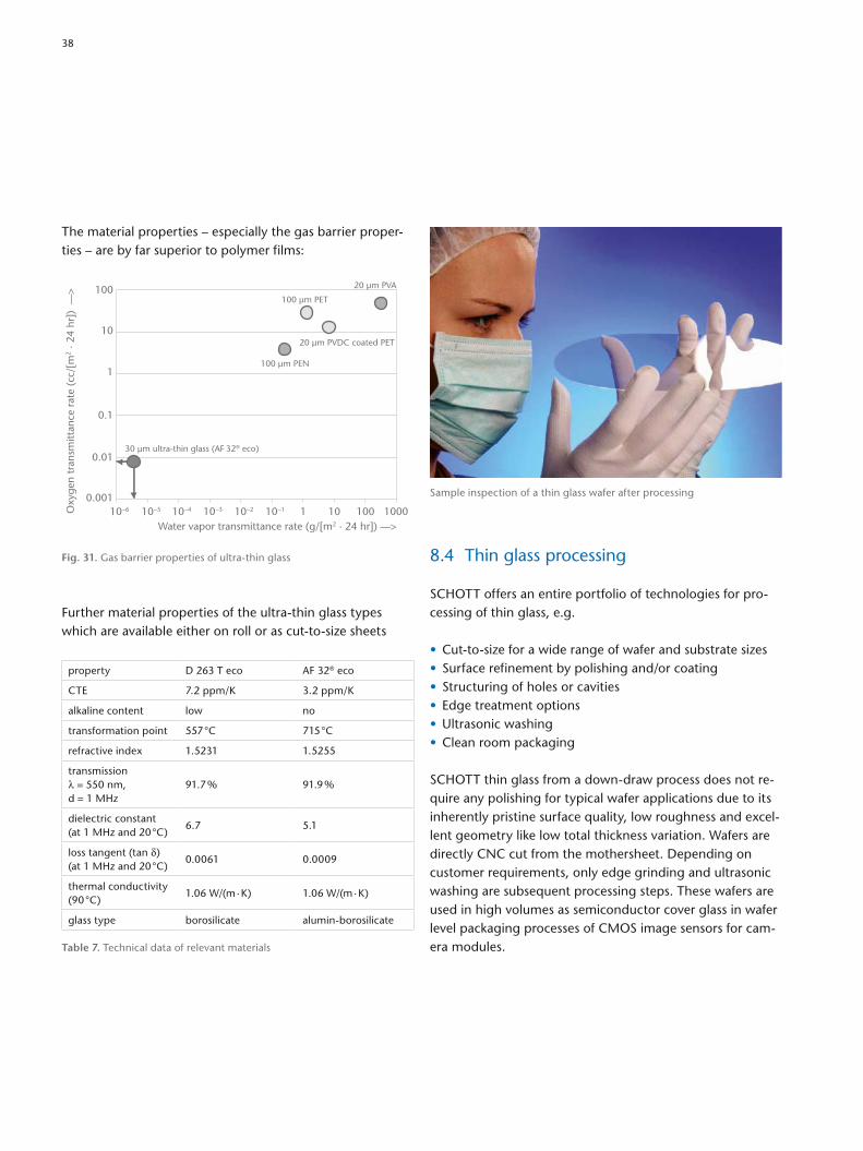
8.4 Thin glass processing
SCHOTT offers an entire portfolio of technologies for processing of thin glass, e.g.
• Cuttosize for a wide range of wafer and substrate sizes• Surface refinement by polishing and/or coating• Structuring of holes or cavities• Edge treatment options• Ultrasonic washing• Clean room packaging
SCHOTT thin glass from a downdraw process does not require any polishing for typical wafer applications due to its inherently pristine surface quality, low roughness and excellent geometry like low total thickness variation. Wafers are directly CNC cut from the mothersheet. Depending on customer requirements, only edge grinding and ultrasonic washing are subsequent processing steps. These wafers are used in high volumes as semiconductor cover glass in wafer level packaging processes of CMOS image sensors for camera modules.
The material properties – especially the gas barrier properties – are by far superior to polymer films:
Oxy
gen
tran
smitt
ance
rat
e (c
c/[m
2 · 2
4 hr
]) –
–>
Water vapor transmittance rate (g/[m2 · 24 hr]) ––>
20 µm PVA
20 µm PVDC coated PET
30 µm ultra-thin glass (AF 32® eco)
100 µm PET
100 µm PEN
10–6 10–5 10–4 10–3 10–2 10–1 1 10 100 10000.001
1
0.1
0.01
10
100
Fig. 31. Gas barrier properties of ultrathin glass
Further material properties of the ultrathin glass types which are available either on roll or as cuttosize sheets
property D 263 T eco AF 32® eco
CTE 7.2 ppm/K 3.2 ppm/K
alkaline content low no
transformation point 557 °C 715 °C
refractive index 1.5231 1.5255
transmission λ = 550 nm, d = 1 MHz
91.7 % 91.9 %
dielectric constant (at 1 MHz and 20 °C)
6.7 5.1
loss tangent (tan δ)(at 1 MHz and 20 °C)
0.0061 0.0009
thermal conductivity (90 °C)
1.06 W/(m · K) 1.06 W/(m · K)
glass type borosilicate aluminborosilicate
Table 7. Technical data of relevant materials
Sample inspection of a thin glass wafer after processing
38

Applications of structured glass wafers and substrates with holes and cavities are in the electronics industry, e.g. for MEMS capping wafers and in the biotech industry, e.g. for flow cells for blood analysis. The two major technologies currently applied by SCHOTT for structuring and their technical capabilities are:
Ultrasonic lapping Powder blasting
Size 100 mm to 200 mm Max. 400 mm x 400 mm
Thickness range 0.4 mm up to 3 mm 0.05 mm up to 3 mm
Different hole configurations
Round holes Round, rectangular holes and caverns
Positioning tolerances
± 65 µm* ± 65 µm*
Min. hole diameter
0.4 mm 0.1 mm
* Tighter tolerances upon request
Table 8. Structured technologies and technical capabilities
For processing of ultrathin glass, new laserbased processes are under design to cut the glass but also to generate a high number of holes with diameters around 50 microns as TGVs (through glass vias) in printed circuit board and interposer applications.
Hole
US-Lapping shape
Glass Thickness
Powder Blasting shapeØB
ØC
A
HoleGlass Thickness
A: hole angle (based on B and C)B: inlet diameterC: outlet diameter
Cavity by Powder Blasting
Radius at the edges
Glass Thickness
Structured glass wafer
Flow cell for DNA analysis, structured into SCHOTT thin glass TGV technology with SCHOTT AF 32® eco 100 µm ultrathin glass processed by excimer laser at 193 nm wavelength
8
39

8.5 Antireflective glasses for technical applications (CONTURAN®/DARO)
8.5.1. CONTURAN® CONTURAN® is an antireflective coating on both surfaces based on optical interference coatings, which can be used for technical applications i.e. front panels of visual display units, televisions, display panels, public displays.
The multilayer coating is applied by way of a sol gel process that uses dip coating technology. As shown in Fig. 32a, three different layers are subsequently formed simultaneously on both surfaces of the glass. The refractive index of the layers is varied by the composition of the sol gel solution. SiO2 is used as a low index material and TiO2 for the high refractive index. In standard float glass, without an interference coating, about 8 % of light is reflected backwards to the observer (Fig. 32b, lower picture). The interference coating creates a design, which reduces reflecting light waves significantly. As shown in Fig. 32b, less than 1 % of light is now reflected. This reduction of the reflection leads to an enhanced contrast for pictures or displays behind CONTURAN® cover plates. The coating is designed to reduce the reflection in the visual wavelength region of approximately 400 to 700 nm. Fig. 33 shows the reflection curve for two distinctive coating designs used in the CONTURAN® product portfolio. The “green hue” coating is a design used in standard optics. The “blue hue” coating yields a distinct residual blue reflection often desired in technical, designoriented applications.
8.5.2. Applications of CONTURAN® Mineralbased cover plates are often used in display applications to protect the display from mechanical damage. However, the reflection of light on the glass reduces the contrast of the display, especially when used outdoors. One of the most obvious examples is the usage of smartphone outdoors, where the excellent display performance often is completely wiped out by the sunlight. CONTURAN® with its low reflection is exactly designed to maintain the contrast of the display by reducing undesired reflections. Popular examples for applications are automotive displays, public displays and professional displays used for automatization.
Re�e
ctan
ce ρ
in %
––>
Wavelength in nm ––>
0.0
10.0
8.0
6.0
4.0
2.0
425 450 475 500 525 550 575 600 625 650 675 700
Clear �oat glass (standard)Blue-violet anti-re�ective coating
Green anti-re�ective coating
Fig. 33. Reflection spectrum of CONTURAN®: Comparison of “blue hue” and “green hue” reflection
Glass substrate
SiO2
SiO2 +
TiO2
TiO2
TiO2
SiO2 +
TiO2
SiO2
CONTURAN®
Transmittance
Exposure to light
Reflectance
< 1 %> 98 %
Absorptance in the glass ~ 1 %
100 %
Standard float glass
Transmittance
Exposure to light
Reflectance
~ 8 %~ 91 %
Absorptance in the glass ~ 1 %
100 %
Fig. 32a. Three layer coating design Fig. 32b. Effect of antireflective coatings on the reflection of light
40
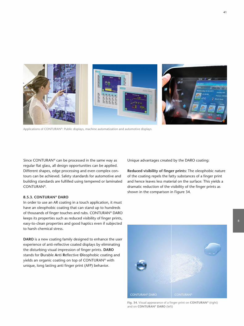
Since CONTURAN® can be processed in the same way as regular flat glass, all design opportunities can be applied. Different shapes, edge processing and even complex contours can be achieved. Safety standards for automotive and building standards are fulfilled using tempered or laminated CONTURAN®.
8.5.3. CONTURAN® DARO In order to use an AR coating in a touch application, it must have an oleophobic coating that can stand up to hundreds of thousands of finger touches and rubs. CONTURAN® DARO keeps its properties such as reduced visibility of finger prints, easytoclean properties and good haptics even if subjected to harsh chemical stress.
DARO is a new coating family designed to enhance the user experience of antireflective coated displays by eliminating the disturbing visual impression of finger prints. DARO stands for Durable Anti Reflective Oleophobic coating and yields an organic coating on top of CONTURAN® with unique, long lasting anti finger print (AFP) behavior.
Unique advantages created by the DARO coating:
Reduced visibility of finger prints: The oleophobic nature of the coating repels the fatty substances of a finger print and hence leaves less material on the surface: This yields a dramatic reduction of the visibility of the finger prints as shown in the comparison in Figure 34.
CONTURAN® DARO CONTURAN®
Fig. 34. Visual appearance of a finger print on CONTURAN® (right) and on CONTURAN® DARO (left)
Applications of CONTURAN®: Public displays, machine automatization and automotive displays
8
41
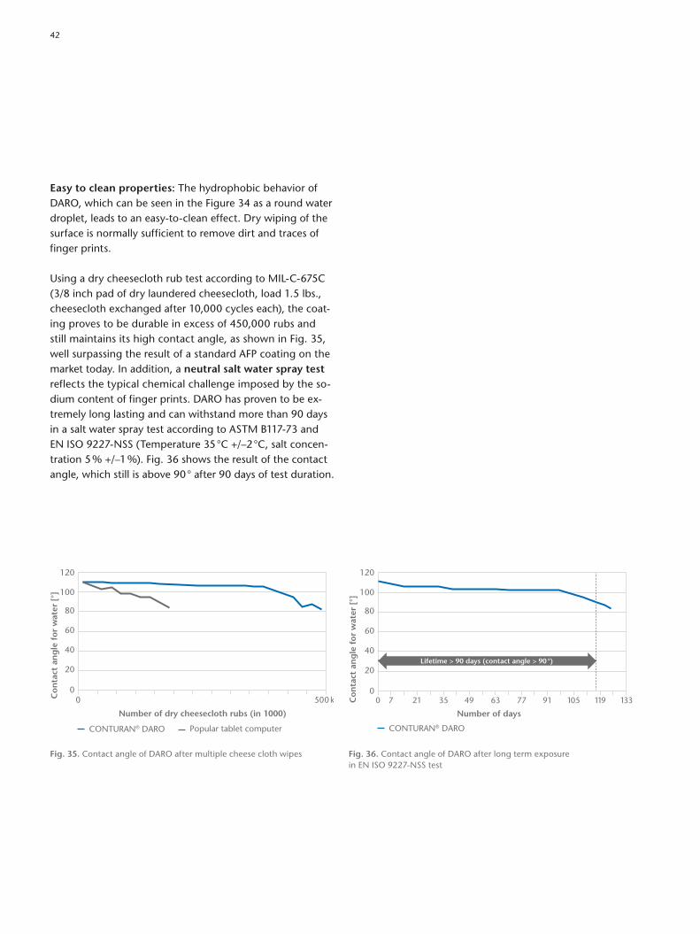
Easy to clean properties: The hydrophobic behavior of DARO, which can be seen in the Figure 34 as a round water droplet, leads to an easytoclean effect. Dry wiping of the surface is normally sufficient to remove dirt and traces of finger prints.
Using a dry cheesecloth rub test according to MILC675C (3/8 inch pad of dry laundered cheesecloth, load 1.5 lbs., cheesecloth exchanged after 10,000 cycles each), the coating proves to be durable in excess of 450,000 rubs and still maintains its high contact angle, as shown in Fig. 35, well surpassing the result of a standard AFP coating on the market today. In addition, a neutral salt water spray test reflects the typical chemical challenge imposed by the sodium content of finger prints. DARO has proven to be extremely long lasting and can withstand more than 90 days in a salt water spray test according to ASTM B11773 and EN ISO 9227NSS (Temperature 35 °C +/–2 °C, salt concentration 5 % +/–1 %). Fig. 36 shows the result of the contact angle, which still is above 90 ° after 90 days of test duration.
CONTURAN® DARO
0 7 21 35 49 63 77 91 105 119 133
Number of days
120
100
80
60
40
20
0
Co
nta
ct a
ng
le f
or
wat
er [
°]
Lifetime > 90 days (contact angle > 90°)
0 500 k
Number of dry cheesecloth rubs (in 1000)
CONTURAN® DARO Popular tablet computer
120
100
80
60
40
20
0
Co
nta
ct a
ng
le f
or
wat
er [
°]
Fig. 35. Contact angle of DARO after multiple cheese cloth wipes Fig. 36. Contact angle of DARO after long term exposure in EN ISO 9227NSS test
42
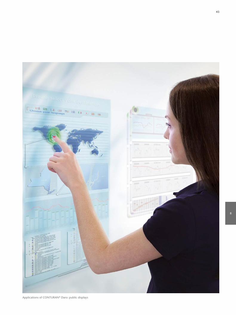
Applications of CONTURAN® Daro: public displays
8
43

Apart from characteristic material values such as coefficient of linear thermal expansion, transformation temperature, and elastic properties, the cooling rate (Figure 37) and the shape can also have considerable influence on the degree and distribution of seal stresses.
9.1.2 Matching glassesIn reference to the expansion coefficients of technically applied sealing metals (e.g. tungsten and molybdenum) and alloys (of NiFeCo, NiFeCr, and other special materials), the corresponding sealing glasses are grouped and designated as “tungsten sealing glasses,” “Kovar glasses,” etc. (see Table 9).
Alkaline earth borosilicate glasses (8412) and alumino silicate glasses (8252, 8253) have the necessary sealability and thermal resistance to be particularly suitable for tungsten and molybdenum sealings frequently used in heavyduty lamps.
Tungsten is very often used as a metal wire for highly developed and highly stressed seals. For this, a group of glass types with additional properties are available (8487).
NiFeCo (Kovar) alloys are of great importance as substitutes for molybdenum. Suitable glasses (8245 and 8250) characteristically contain relatively high amounts of B2O3. These glasses have additional special properties, such as high electrical insulation, low dielectric loss and low Xray absorption, and meet the most stringent requirements for vacuum tube technology and electronic applications.
9.1 Sealing glasses
9.1.1 General informationGlasses are best suited for the production of mechanically reliable and vacuumtight fusion seals with metals and ceramics. Particularly favored properties are the viscosity behavior of glass and the direct wettability of many crystalline materials by glasses.
A necessary condition for the stability and mechanical strength of glass seals is the limitation of mechanical stress in the glass component for temperatures encountered during production and use. To ensure “sealability” (which means that the thermal contractions of the two sealing components match each other below the trans formation temperature of the glass), glasses of a special composition, socalled sealing glasses, are often developed. Apart from sealability, such glasses must very often fulfill other requirements such as high electrical insulation, special optical properties, etc. The sealability can be tested and evaluated with sufficient accuracy and certainty by stressoptical measurements in the glass portion of a test seal (ISO 4790).
9. Glasses for Joinings
Op
tical
pat
h di
ffere
nce
=̂ Se
alin
g st
ress
in n
m/c
m –
–>
Temperature in °C ––>Compression
Tension
–200
–400
0
200
400
600
800
1000
1000 200 300 400 500 600
Fig. 37. Influence of cooling rate on the temperature–sealing stress relationship in a 8516–52 Ni/Fe combination; blue curve: low cooling rate, black curve: high cooling rate
Reed switches encapsulated in SCHOTT glass type 8516
44
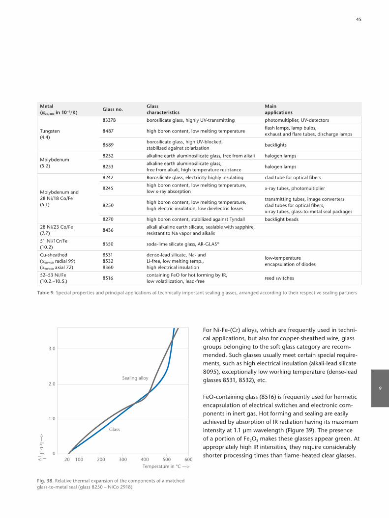
For NiFe(Cr) alloys, which are frequently used in technical applications, but also for coppersheathed wire, glass groups belonging to the soft glass category are recommended. Such glasses usually meet certain special requirements, such as high electrical insulation (alkalilead silicate 8095), exceptionally low working temperature (denselead glasses 8531, 8532), etc.
FeOcontaining glass (8516) is frequently used for hermetic encapsulation of electrical switches and electronic components in inert gas. Hot forming and sealing are easily achieved by absorption of IR radiation having its maximum intensity at 1.1 µm wavelength (Figure 39). The presence of a portion of Fe2O3 makes these glasses appear green. At appropriately high IR intensities, they require considerably shorter processing times than flameheated clear glasses.
Temperature in °C ––>
––>
Δ I I
[10–3
]
0
1.0
2.0
3.0
100
Sealing alloy
Glass
20 200 300 400 500 600
Fig. 38. Relative thermal expansion of the components of a matched glasstometal seal (glass 8250 – NiCo 2918)
Metal(α20/300 in 10–6/K)
Glass no.Glasscharacteristics
Main applications
Tungsten(4.4)
8337B borosilicate glass, highly UVtransmitting photomultiplier, UVdetectors
8487 high boron content, low melting temperatureflash lamps, lamp bulbs, exhaust and flare tubes, discharge lamps
8689borosilicate glass, high UVblocked, stabilized against solarization
backlights
Molybdenum(5.2)
8252 alkaline earth aluminosilicate glass, free from alkali halogen lamps
8253alkaline earth aluminosilicate glass, free from alkali, high temperature resistance
halogen lamps
Molybdenum and28 Ni/18 Co/Fe(5.1)
8242 Borosilicate glass, electricity highly insulating clad tube for optical fibers
8245high boron content, low melting temperature,low xray absorption
xray tubes, photomultiplier
8250high boron content, low melting temperature,high electric insulation, low dieelectric losses
transmitting tubes, image convertersclad tubes for optical fibers,xray tubes, glasstometal seal packages
8270 high boron content, stabilized against Tyndall backlight beads
28 Ni/23 Co/Fe(7.7)
8436alkali alkaline earth silicate, sealable with sapphire,resistant to Na vapor and alkalis
51 Ni/1Cr/Fe(10.2)
8350 sodalime silicate glass, ARGLAS®
Cusheathed(α20/400 radial 99)(α20/400 axial 72)
853185328360
denselead silicate, Na andLifree, low melting temp.,high electrical insulation
lowtemperatureencapsulation of diodes
52–53 Ni/Fe(10.2.–10.5.)
8516containing FeO for hot forming by IR, low volatilization, leadfree
reed switches
Table 9. Special properties and principal applications of technically important sealing glasses, arranged according to their respective sealing partners
9
45

9.1.3 Intermediate sealing glassesGlasses whose thermal expansion differs so widely from that of the partner component that direct sealing is impossible for stress reasons, must be sealed with intermediate sealing glasses. These glasses are designed for the recommended seal transitions in such a way that the sealing stresses do not exceed 20 N/mm2 at room temperature.
Glass no. Sealing partners α20/300 Transformation temperature
Glass temperature at viscosities Density tk100
1013 dPa · s 107,6 dPa · s 104 dPa · s
[10–6/K] [°C] [°C] [°C] [°C] [g/cm3] [°C]
8228 Fused silica–8228–8229 1.3 700 726 1200 1705 2.15 355
8229 8228–8229–8230 2.0 630 637 930 1480 2.17 350
8230 8229–8230–8330 2.7 570 592 915 1520 2.19 257
8447 8412–8447–Vacon 10 4.8 480 505 720 1035 2.27 271
8448 8330–8448–8449, 8486, 8487 3.7 510 560 800 1205 2.25 263
84498486 –8449– 84128487 } 8447
4.5 535 550 785 1150 2.29 348
84508412–8450–KER 2208436
5.4 570 575 778 1130 2.44 200
8454KER 221 –8454–Vacon 70Al2O3
} 6.4 565 575 750 1070 2.49 210
84558436 –8455– 84568454
6.7 565 – 740 1030 2.44 –
8456 8455–8456–8350 7.4 445 – 685 1145 2.49 –
Note: type designation of the ceramics to DIN 40685; manufacturer of Vaconalloys: Vacuumschmelze Hanau (VAC)
Table 10. Sealing and intermediate sealing glasses
Tran
smis
sion
in %
––>
Wavelength in nm ––>200 500 1000 2000 5000 100000
20
10
40
30
60
80
100
90
70
50Thickness 0.5 mm
Thickness 1 mm
Emission spectrum of atungsten halogen lamp
Fig. 39. IR absorption of Fedoped glasses compared to the emission of halogen lamps. Transmission of reed glass 8516, thicknesses 0.5 mm and 1 mm, and emission of a tungsten halogen lamp (3000 K, rel. unit)
46

Glasstometal sealed housings and feedthroughs reliably protect sensitive electronics in harsh conditions such as humidity, temperature fluctuations, pressure or aggressive chemicals.
9
47

1 2 3
9.1.4 Compression sealsA common feature of all compression seals is that the coefficient of thermal expansion of the external metal part is considerably higher than the thermal expansion coefficients of the sealing glass and the metallic inner conductors. As a result, the glass body is under overall radial pressure after the sealing. This prestressing protects the glass body against dangerous mechanical loads and guarantees robust, mechanically insensitive seals. Because the compressive stress of the glass is compensated by tensile stress in the jacket, the jacket wall must be sufficiently thick (at least 0.5 mm even for small seals) in order to be able to absorb such tensions permanently. Like adapted seals, compression seals can be produced as hard glass or soft glass seals. If the difference of the thermal expansion of the metallic jacket and the sealing glass is significantly higher than 5 ppm/K, an additional prestressing of the glass body results (“reinforced compression seal”); see Figure 40.
Temperature in °C ––>
1
8
8421
Steel
Radial tension
6
7
5
4
3
2
0 100 200 300 400 500
––>
Δ I I
[10–3
]
Fig. 41. Relative thermal expansion of the glass and metal (compression ring) of a compression glasstometal seal
Fig. 40. Schematic representation of a compression glasstometal seal 1 = external lead, 2 = glass, 3 = internal tubular lead
48

α(20/300) [10–6 K–1]
Designation Compression ring Glass Interior lead
Standard compression glasstometal seals 13 9 9
Lowexpansion standard compressionglasstometal seals
9 5 5
Reinforced compressionglasstometal seals
1813
95 – 7
95
Table 11. Expansion coefficients of common material combinations for compression glasstometal seals
Glass no.
Main applications
α(20/300) Transfor-mation tempera-ture Tg
Glass temperatures in °C at viscosities dPas
Density tk100 log of the electric volume- resistivity in Ω cm at
Dielectric properties at 25 °C for 1 MHz
Chemical resistance classes
[10–6 1K] [°C] 107,6 104 [g/cm3] [°C] 250 °C 350 °C DZ tanδ [10–4] W S L
8350Compression seals Seals with steelsand NiFe alloys
9.0 520 708 1035 2.52 198 7.1 5.7 7.2 70 3 1 2
8421Compression sealsSeals with steelsand NiFe alloys
9.6 525 721 1000 2.59 253 8.1 6.4 7.4 43 3 3 2
8422Compression sealsSeals with steelsand NiFe alloys
8.6 540 722 1027 2.46 212 7.3 5.8 7.3 60 2 3 3
8629Compression sealsSeals with steelsand NiCo 2918
7.6 529 720 1020 2.52 267 8.3 6.7 6.4 26 1 3 2
8630
Compression seals Seals with steels and NiFe alloys, increased requirements for electrolytic resistance and temperature stability
9.1 440 660 975 2.53 317 9.3 7.6 6.5 21 3 1/2 2
Table 12. Sealing glasses for compression seals
9
49

3
2
4
5
6
7
8
9
10
11
4
2
3
5
6
7
8
9
10
11
8229
8228
8230
8487
Al2O3-Ceramic
SteatiteKER 220/221
Sapphir
Vacon 70
Forsterite KER 250
Cu-sheathed wire
8531
8532
8405
Fused silica
8651
8330
8455
8456
8454
8450
Vacovit 501Platinum
8095
Vacovit 465-485
51-53 Ni-Fe
51 Ni-1 Cr-Fe
8449
8448
8447
8337 b8660
Tungsten
8652
82528253
8650
Molybdenum8245
8242Kovar/Vacon 10 8250
8516
8625
8436
8350
Ceramics Glasses Metals α (20 °C/300 °C) [10–6K]
Technical glasses
Intermediate sealing glasses
Producible seals, limited with regard to size and geometry, with stresses between 8 N/mm2 and 20 N/mm2 at room temperature
Triedout, unrestricted seals with stresses ≤ 8 N/mm2 at room temperature
Table 13. Graded seals
50

• Seals can be achieved through conventional heating (in a furnace) as well as through laser welding
• Glass sealants have excellent electrical insulation• Sealants are available in powder, paste and preform
formats
9.2 Glass and glassceramic sealants for technical ceramics
Dielectrically superior and highly insulating ceramics such as hard porcelain, steatite, Al2O3 ceramics, and forsterite exhaust almost the complete expansion range offered by technical glasses. Hard porcelain can generally be sealed with alkaline earth borosilicate glasses, which are also compatible with tungsten. Glass seals with Al2O3 ceramics and steatite are possible with special glasses such as 8436, which will also seal with 28 Ni/18 Co/Fe alloy. Soft glasses with thermal expansions around 9 x 10⁻⁶/K are suitable for sealing to forsterite.
Aluminum oxide, zirconium oxide and silicon carbide have high temperature resistance. Hence, these ceramics are commonly used in hightemperature sensor applications such as in the combustion chamber or exhaust track of automobiles.
SCHOTT has developed special glasses and glassceramics for the joining of these technical ceramics. The sealants are stable at elevated temperatures and are chemically resistant, thereby contributing to the stability of the ceramic applications over an extended period of time.
Advantages • CTEmatched sealing glasses for Al2O3, ZrO2 and SiC
substrates• Sealing glasses are available for operating tempera
tures in the range 530 – 1040 °C and CTE in the range 4.6 – 9.8 x 10⁻⁶/K
Sealing partnerSCHOTT glass number
CTE* (10–6/K for 20 – 300 °C)
Tg (°C)Sealing temperature (°C)
Maximum operating temperature (°C)
SiC 8253 4.6 785 1320 735
AIN G018200 4.6 557 665 550
Al2O3
G018266 6.9 585 770 530
G018346 7.3 720 1270 670
G0183588.5 8.8 **
658 940600 1040 **
G018385 8.4 ** 992 950 950 °C (1000)
ZrO2
G018339 9.2 ** 627 990 760 **
G0183119.1 9.9 **
622 850560 880 **
* CTE = coefficient of thermal expansion ** p.c. = partially crystalline
Table 14. Sealing glasses for hightemperature applications
Joining of SiC ceramic with SCHOTT sealing glass
9
51

9.3 Glass and glassceramic sealants for solid oxide fuel cells (SOFC) / sold elecholyzer cells / SO EC
SOFC sealing materials are specially formulated glasses and glassceramics that withstand the harsh environments and high operating temperatures of SOFCs. Sealing glass pastes made of glass powder and an organic binding agent are applied to the interconnects through dispensing or screen printing. Green sheets are also available upon request.
Besides providing hermetic sealing, i.e. inhibiting fueloxidant mixing, the sealing material also serves as electrical insulation with high electrical resistance at operating temperatures. Moreover, they feature chemical stability under reducing and oxidizing atmospheres and have a matched coefficient of thermal expansion (CTE) to prevent material stress within the structure.
Advantages• Ideal thermal cycling achieved by perfectly matched CTE
to the interconnects and ceramic components • Crystallizing glasses and glassceramic composites with a
stable structure for constant longlasting properties• High amorphous glass phase for “selfhealing” character
istics• Usage of materials with a broad range of sealing tempera
tures available• Excellent electrical insulation • Alkaline free
Glass and glassceramic sealants
Glass no.α(20–300) [ppm/K] *
Tg [°C]* Dil. Ew [°C]* p [g/cm3]Sealing temperature [°C]
Sealing partners
GM31107 9.8 543 592 3.70 700 Crofer, ITM, StS
G018281 12.1 639 > 850 2.70 1000 CFY
G018311 9.9 612 686 3.80 850 Crofer, ITM, StS
G018354 9.2 637 711 3.90 850 Crofer, ITM, StS
G018381 12.1 652 > 850 2.30 950 CFY
G018385 8.4 992 > 1000 3.14 1000 CFY
* partially crystalline
Table 15. SOFC sealing glasses
Air
AirFuel
Exhaust gas
Glass sealing metal to metal
Glass sealing ceramic to metal
52

9.4 Solder glasses
Solder glasses are special glasses with a particularly low softening point. They are used to join glass to other glasses, ceramics, or metals without thermally damaging the materials to be joined. Soldering is carried out in the viscosity range η = 104 – 106 dPa · s of the solder glass (Figure 42); this usually corresponds to a temperature range Tsolder = 350 – 700 °C.
We distinguish between vitreous solder glasses and devitrifying solder glasses, according to their behavior during the soldering process.
Vitreous solder glasses behave like traditional glasses. Their properties do not change during soldering; upon reheating the solder joint, the temperature dependence of the softening is the same as in the preceding soldering process.
Unlike vitreous solder glasses, devitrifying solder glasses have an increased tendency to crystallize. They change into a ceramiclike polycrystalline state during soldering. The viscosity increases by several orders of magnitude during crystallization so that further flowing is suppressed. This timedependent viscosity behavior is exemplarily shown in Figure 43 for a devitrifying solder glass processed by a specific temperaturetime program.
On the other hand, crystallization allows a stronger thermal reload of the solder joint, normally up to the temperature
range of the soldering process itself. Devitrifying glasses are available upon request.
The development of solder glasses with very low soldering temperatures is limited by the fact that reducing the temperature generally means increasing the coefficient of thermal expansion. This effect is less pronounced in devitrifying solder glasses. It can be even more effectively avoided by adding inert (nonreacting) fillers with low or negative coefficients of thermal expansion (e.g. ZrSiO4 or βeucryptite). Such composite solder glasses are preferably used to produce stable glass solders.
lgη
in d
Pa·s
––>
Temperature in °C ––>200 400 600 800 1000 12000
6
4
2
10
8
12
14
16
Solderingzone
Solder glass
Glass
Transformation range
lgη
in d
Pa·s
––>
Tem
per
atur
e in
°C
––>
Time in min ––>0 2010 30 40 50 60
4
8
6
10
14
12
300
350
400
500
450
Temperature
lg η
Fig. 42. Viscosities η of solder glass to be soldered Fig. 43. Viscosity development of a crystallizing solder glass during soldering
Panes of flat glass AF 45 bonded with composite solder glass
9
53

is a necessary prerequisite for stable, gas/leaktight joins. As a rule, the coefficient of thermal expansion of the solder glasses should be by Δα = 0.5 – 1.0 x 10⁻⁶/K smaller than the expansion coefficients of the sealing partners.
The relationship between soldering temperature and thermal expansion is schematically shown in Figure 44.
With devitrifying solder glasses, one must consider that the expansion coefficients given in the respective lists of properties are only valid on condition that the specific soldering program defined for each solder glass is complied with. Changing the soldering program, in particular the soldering temperature and the soldering time, may affect the relationship between glassy and crystalline phase and thus change the coefficient of thermal expansion, with the possible result of a mismatch.
Sealing joints produced with vitreous solder glasses can be loaded to approximately 50 K below the transformation temperature of the respective solder glass. The maximum service temperature of devitrifying solder glasses depends on the type and melting point of the precipitated crystals and on the amount and properties of the residual glass phase. Up to maximum service temperature, solder glasses are moisture and gasproof. Their good electric insulating property is superior to that of many standard technical glasses. They are therefore also suitable as temperature resistant insulators. The chemical resistance of solder glasses is generally lower than that of standard technical glasses. Therefore, solder glass sealings can be exposed to chemically
Because fillers reduce the flow capability during the soldering process, they can be added to the batch only in limited amounts.
Taking into consideration the properties of the materials to be joined, suitable solder glasses are mainly selected under the following aspects:1. highest permissible soldering temperature,2. thermal expansion of the materials to be joined,3. maximum application temperature of the solder zone, 4. chemical behavior.
ProcessingTo achieve satisfactory soldering, the solder glass must flow sufficiently and wet the parts to be joined well. Flow and wetting are temperature and timecontrolled; the higher the temperature, the less time is required for sufficient flow, and vice versa.
Thus, soldering at high temperatures may take only a few minutes, whereas at low temperatures (i.e. at viscosities ≥ 107 dPa · s) reaching sufficient flow takes very long and usually can be achieved only under additional mechanical load.
PropertiesAs with all sealings involving glass, adapting the thermal expansions of the components to be joined with solder glass
α(2
0/30
0) –
–>
Soldering temperature in °C ––>
4
2
6
8
10
12
400 450 500 550 650600 700
Vitreous solder glass
Devitrifying solder glass
Composite
Fig. 44. Relationship between soldering temperature and linear expansion α for solder glasses. The curves describe the lowest limits for the respective solder glass types.
Spherical lense (center) sealed to a metal casing with a sintered solder glass ring
54

aggressive environments (e.g. acids, alkaline solutions) only for a limited time.
Deliverable forms and shapesSolder glass can be supplied in the form of powder, granulate and sintered preforms (e.g. rings, rods, …), and as paste. An example of a glasstometal seal application is shown on page 50, Table 13.
Glass no. α(20/300) Tg Sealing temperature Density tk100 tanδ
tholding
[10–6 x K–1] [°C] [°C] [min] [g/cm3] [°C] [10–4]
Leadcontaining
G017002 3.7 545 700 15 3.6 – 37
G017339 4.7 325 510 15 4.3 11.5 19
G017712 5.3 375 510 10 – – –
G017393 6.5 320 425 15 4.8 11.6 15
G017340 7.0 315 420 15 4.8 13.4 14
G018228 7.6 311 400 15 5.0 – –
8465 8.2 385 520 60 5.4 14.9 27
G018229 8.7 310 410 15 5.4 – –
G018256 9.6 316 420 15 5.8 – –
G017052 11.7 308 410 15 6.7 – –
Leadfree
G018250 7.0 380 540 15 5.7 – –
G018255 9.4 396 520 15 6.7 – –
8470 10.0 440 680 60 2.8 – –
G018249 10.1 365 500 15 7.1 – –
Other matched CTE available upon customer request All solder glasses are available as K3 powder. Grain size: d50 = 10 ± αµm , d99 ≤ 63µm
Other grain sizes available upon request
Table 16. SCHOTT solder glasses
9
55

9.5 Passivation glasses
Passivation glasses are zincborosilicate and leadalumina silicate glasses used for chemical and mechanical protection of semiconductor surfaces.
ProcessingTo avoid distortion and crack formation, the different co efficients of thermal expansion of the passivation glass and the other semiconductor components must be taken into account. If the mismatch is too large, a network of cracks will originate in the glass layer during cooling or subsequent processing and destroy the hermetic protection of the semiconductor surfaces. Basically, there are three ways of overcoming this problem:
The thinner the passivation glass layer, the smaller is the risk of cracking. SCHOTT therefore recommends maximum thicknesses for all homogeneous passivation layers that, as a rule, should not be exceeded.
The sealing stress between glass and silicon, and thus the risk of cracking, can be reduced by slow cooling in the transformation range. As a rough rule, a cooling rate of 5 K/min is suitable for passivation layers in the temperature range Tg ± 50 K.
Another way of avoiding thermal expansion mismatches is using composite glasses. Composites consist of a mixture of passivation glass powder and an inert filler such as, for ex
ample, powdered ceramics with very low or negative thermal expansion. Such fillers lower the mean thermal expansion coefficient of the passivation glass and thus minimize or eliminate the risk of cracking. As a secondary effect, fillers improve the mechanical stability of the composite glass.
Different processing techniques, adjusted to the requirements of the respective applications, are employed. For the manufacturing of sintered glass diodes, usually a slurry of glass powder and deionized water is applied to the diode body, including the Mo or Wcontact studs. For wafer passivation (glass applied to the Si wafer before separating the chips), an organic suspension is applied by spinning, doctor blading, sedimentation, electrophoresis, or screen printing. The organic suspension vehicles must be completely volatile or thermally decomposable below the softening temperature of the glass.
PropertiesElectrical insulation, including dielectric breakdown resistance, generally depends on the alkali content, particularly on the Na+ content. Alkali contamination in SCHOTT passivation glasses is kept low by selecting pure raw materials and special manufacturing procedures. Contamination is tested for every batch. Typical contents are below 100 ppm for Na2O and K2O, and below 20 ppm for Li2O. Some composite passivation glasses may contain fillers with slightly higher amounts of alkali; because the mobility of alkali ions is negligible, there is no risk of impairing the quality of the component.
Polished section of a glassencapsulated silicon diode Diodes prepared for delivery (e.g. small signal diodes)
56

Forms of supplyPassivation glasses are supplied as glass powders, ground ironfree and with negligible abrasion. Passivation glasses are available as tubing or sleeves for use in certain applications. They are available in various grain sizes (generally type K, see Table 17) to suit the respective application.
Heavy metals which are incompatible with semicon ductors are controlled as well. The CuO content, for example, is below 10 ppm.
Because the mobility of charge carriers increases drastically with increasing temperature, a temperature limit, called junction temperature Tj, is defined up to which glasspassivated components can be used in blocking operations.
In manufacturing, glass passivation is often followed by chemical processes (such as etching of contact windows or electrolytic deposition of contacts) which may attack the glass. The chemical resistance of the various passivation glasses differs strongly and is an important criteria in selecting the appropriate glass type. Zincborosilicate glasses, for instance, are highly sensitive to chemical attack by acids and alkaline solutions and therefore only recommended for use with contacts applied by sputtering.
Lead- containing
Type Main applications
α(20/300)
10–6/K
Tg
°C
Pb contentswt%
Firingtemp.°C
Holdingtimemin.
Tj °C
Layerthicknessµm
G018205 PbZnB sinter glass diodes 4.45 632 1– 5 690 10 – –
G017388 ZnBSi compositethyristors, high blocking rectifiers
3.6 550 1– 5 700 5 180 ≥ 30
G017002 ZnBSi composite sintered glass diodes 3.7 545 1– 5 700 10 180 –
G017096R PbBSisinter glass, planar and mesadiodes
4.8 456 10 – 50 680 5 160 –
G017004 PbBSi composite mesa diodes 4.1 440 10 – 50 740 5 160 ≥ 30
G017230 PbBSi composite transistors 4.2 440 10 – 50 700 4 160 ≥ 25
G017725 PbBSi sinter glass diodes 4.9 468 10 – 50 670 10 180 –
G017997 PbBSi composite wafer passivation 4.4 485 10 – 50 760 20 180 –
G018133 PbBSi composite sinter glass diodes 4.8 463 10 – 50 690 30 – –
Leadfree
G018200 ZnBSi sinter glass diodes 4.6 557 – 665 10 – –
G018197 ZnBSi sinter glass diodes 4.4 557 – 675 10 – –
G018255 BiZnB varistors 9.4 396 – 520 15 – –
Table 17. SCHOTT passivation glasses
9
57

as well as their number and size are predetermined by the glass composition and the annealing program. By appropriate program selection, either transparent, slightly opaque, or highly opaque, nontransparent glassceramics can be produced. Unlike conventional ceramics, these glassceramics are absolutely dense and porefree. To achieve controlled
10.1 Introduction to glassceramics
Glassceramics are distinguished from glass and ceramics by their characteristic manufacturing process (see Figure 45) and by their properties. Not classifiable as glass or as ceramic, they represent a completely new class of materials.
They are manufactured in two principal production steps. In the first step, a batch of exactly defined composition is melted (as for normal glass). The composition is determined by the desired properties of the endproduct as well as by the necessary working properties of the glass. After melting, shapes are produced by pressing, blowing, rolling or casting and then annealed. In this state, the material still exhibits all the typical characteristics of glass.
In the second step, the “glassy” articles are subjected to a specific temperaturetime treatment between 800 – 1200 °C (defined for each composition), by which they are ceramized, i.e. they are transformed into a mainly polycrystalline material. Apart from the crystalline phase with crystals of 0.05 – 5 µm in size, this material contains a residual glass phase of 5 – 50 %.
In the temperature range between 600 – 700 °C, small amounts of nucleating agents (e.g. TiO2, ZrO2 or F) induce precipitation of crystal nuclei. As the temperature increases, crystals grow on these nuclei. Their type and properties
10. GlassCeramics for Industrial Applications and Home Appliances
Tem
per
atur
e in
°C
––>
Time ––>
a
b
c
d
e
0
200
400
600
800
1000
1200
1400
1600
1800
Fig. 45. Temperaturetime schedule for glassceramic production a: melting, b: working, c: nucleation, d: crystallization, e: cooling to room temperature
ΔI/I
in 1
0–4 –
–>
Temperature in °C ––>
0
–5
5
10
15
20
–200 0 200 400 800600
Soda-lime glass
DURAN®/BOROFLOAT® 33/SUPREMAX® borosilicate glass
“α-0”-glass-ceramics
Fig. 46. Thermal expansion of “α0”glassceramics compared to borosilicate glass 3.3 and sodalime glass
Nuc
leat
ion
rate
(N
) an
d C
ryst
al g
row
th r
ate
(C)
resp
. ––>
Temperature ––>
C
N
Nmax
Cmax
Fig. 47. Nucleation rate (N) and crystal growth rate (C) of glasses, related to temperature
58

can be produced (Figure 46 and Table 18). This exceptional property results from the combination of crystalline constituents (such as solid solutions of hquartz, heucryptite or hspodumene), with negative coefficients of thermal expansion, and the residual glass phase of the system, with a positive coefficient of thermal expansion.
Such “α0”glassceramics can be subjected to virtually any thermal shock or temperature variation below 700 °C, whereby wall thickness, wall thickness differences, and complicated shapes are of no significance.
Another technical advantage is the exceptionally high dimensional and shape stability of objects made from these materials, even when subjected to considerable temperature variations.
crystallization in the glass, the temperature difference between the nuclei formation region and the crystal growth region must be sufficiently large (Figure 47). In this way, spontaneous crystallization during hot forming and unwanted crystal growth during nucleation can be avoided.
Like the glass composition, the composition of glassceramics is highly variable. Wellknown compositions lie within the following systems:Li2O–Al2O3–SiO2; MgO–Al2O3–SiO2; CaO–P2O5–Al2O3–SiO2.
Glassceramics of the Li2O–Al2O3–SiO2 system that contain small amounts of alkali and alkaline earth oxides as well as TiO2 and ZrO2 as nucleating agents have achieved great commercial significance. Based on this system, glassceramics with coefficients of linear thermal expansion of close to zero
An application for CERAN® glassceramic cooktop panels: e.g. SCHOTT CERAN® for induction
10
59
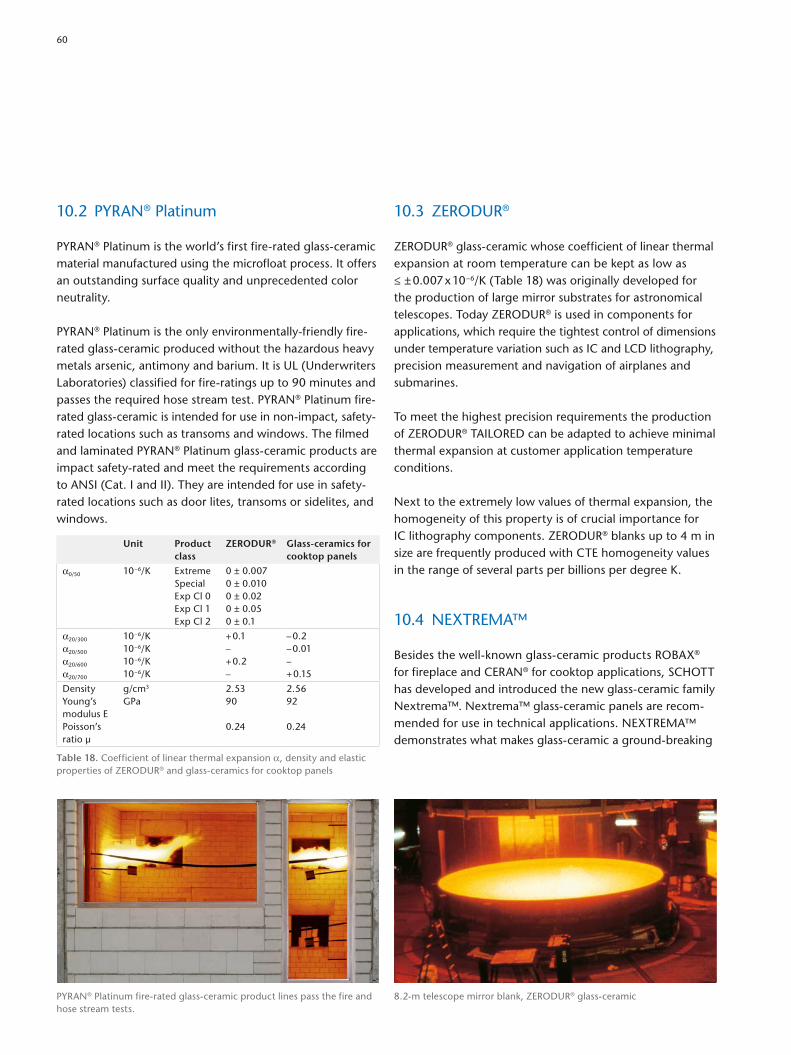
10.3 ZERODUR®
ZERODUR® glassceramic whose coefficient of linear thermal expansion at room temperature can be kept as low as ≤ ± 0.007 x 10⁻⁶/K (Table 18) was originally developed for the production of large mirror substrates for astronomical telescopes. Today ZERODUR® is used in components for applications, which require the tightest control of dimensions under temperature variation such as IC and LCD lithography, precision measurement and navigation of airplanes and submarines.
To meet the highest precision requirements the production of ZERODUR® TAILORED can be adapted to achieve minimal thermal expansion at customer application temperature conditions.
Next to the extremely low values of thermal expansion, the homogeneity of this property is of crucial importance for IC lithography components. ZERODUR® blanks up to 4 m in size are frequently produced with CTE homogeneity values in the range of several parts per billions per degree K.
10.4 NEXTREMA™
Besides the wellknown glassceramic products ROBAX® for fireplace and CERAN® for cooktop applications, SCHOTT has developed and introduced the new glassceramic family Nextrema™. Nextrema™ glassceramic panels are recommended for use in technical applications. NEXTREMA™ demonstrates what makes glassceramic a groundbreaking
10.2 PYRAN® Platinum
PYRAN® Platinum is the world’s first firerated glassceramic material manufactured using the microfloat process. It offers an outstanding surface quality and unprecedented color neutrality.
PYRAN® Platinum is the only environmentallyfriendly firerated glassceramic produced without the hazardous heavy metals arsenic, antimony and barium. It is UL (Underwriters Laboratories) classified for fireratings up to 90 minutes and passes the required hose stream test. PYRAN® Platinum firerated glassceramic is intended for use in nonimpact, safety rated locations such as transoms and windows. The filmed and laminated PYRAN® Platinum glassceramic products are impact safetyrated and meet the requirements according to ANSI (Cat. I and II). They are intended for use in safety rated locations such as door lites, transoms or sidelites, and windows.
Unit Product class
ZERODUR® Glass-ceramics for cooktop panels
α0/50 10–6/K ExtremeSpecialExp Cl 0Exp Cl 1Exp Cl 2
0 ± 0.0070 ± 0.0100 ± 0.020 ± 0.050 ± 0.1
α20/300
α20/500
α20/600
α20/700
10–6/K10–6/K10–6/K10–6/K
+ 0.1–+ 0.2–
– 0.2– 0.01–+ 0.15
DensityYoung’smodulus EPoisson’s ratio µ
g/cm3
GPa
2.5390
0.24
2.5692
0.24
Table 18. Coefficient of linear thermal expansion α, density and elastic properties of ZERODUR® and glassceramics for cooktop panels
8.2m telescope mirror blank, ZERODUR® glassceramicPYRAN® Platinum firerated glassceramic product lines pass the fire and hose stream tests.
60
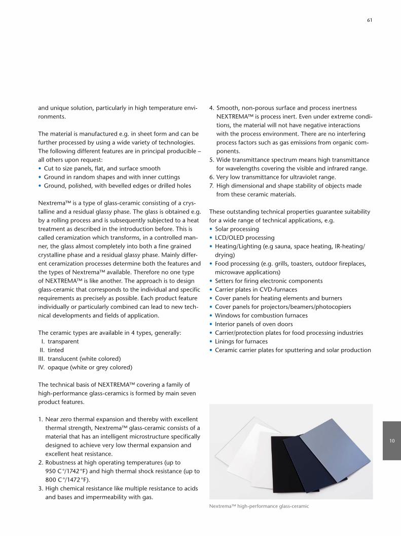
4. Smooth, nonporous surface and process inertness NEXTREMA™ is process inert. Even under extreme conditions, the material will not have negative interactions with the process environment. There are no interfering process factors such as gas emissions from organic components.
5. Wide transmittance spectrum means high transmittance for wavelengths covering the visible and infrared range.
6. Very low transmittance for ultraviolet range.7. High dimensional and shape stability of objects made
from these ceramic materials.
These outstanding technical properties guarantee suitability for a wide range of technical applications, e.g. • Solar processing• LCD/OLED processing• Heating/Lighting (e.g sauna, space heating, IRheating/
drying)• Food processing (e.g. grills, toasters, outdoor fireplaces,
microwave applications)• Setters for firing electronic components• Carrier plates in CVDfurnaces• Cover panels for heating elements and burners• Cover panels for projectors/beamers/photocopiers• Windows for combustion furnaces• Interior panels of oven doors• Carrier/protection plates for food processing industries• Linings for furnaces• Ceramic carrier plates for sputtering and solar production
and unique solution, particularly in high temperature environments.
The material is manufactured e.g. in sheet form and can be further processed by using a wide variety of technologies. The following different features are in principal producible – all others upon request:• Cut to size panels, flat, and surface smooth• Ground in random shapes and with inner cuttings• Ground, polished, with bevelled edges or drilled holes
Nextrema™ is a type of glassceramic consisting of a crystalline and a residual glassy phase. The glass is obtained e.g. by a rolling process and is subsequently subjected to a heat treatment as described in the introduction before. This is called ceramization which transforms, in a controlled manner, the glass almost completely into both a fine grained crystalline phase and a residual glassy phase. Mainly different ceramization processes determine both the features and the types of Nextrema™ available. Therefore no one type of NEXTREMA™ is like another. The approach is to design glassceramic that corresponds to the individual and specific requirements as precisely as possible. Each product feature individually or particularly combined can lead to new technical developments and fields of application.
The ceramic types are available in 4 types, generally: I. transparent II. tintedIII. translucent (white colored)IV. opaque (white or grey colored)
The technical basis of NEXTREMA™ covering a family of highperformance glassceramics is formed by main seven product features.
1. Near zero thermal expansion and thereby with excellent thermal strength, Nextrema™ glassceramic consists of a material that has an intelligent microstructure specifically designed to achieve very low thermal expansion and excellent heat resistance.
2. Robustness at high operating temperatures (up to 950 C °/1742 °F) and high thermal shock resistance (up to 800 C °/1472 °F).
3. High chemical resistance like multiple resistance to acids and bases and impermeability with gas.
Nextrema™ highperformance glassceramic
10
61

11.1 Introduction of Advanced Optics
SCHOTT Advanced Optics – Your Partner for Excellence in Optics.Today, the Advanced Optics unit of SCHOTT offers optical materials, components and filters and has been a trailblazer for various applications.
With a product portfolio of over 120 optical glasses, special materials (e.g. active laser glass, IRMaterials, sapphire), ultrathin glass, highprecision optical components, wafers, and optical filter glasses, Advanced Optics develops customized solutions all over the world for applications in optics, lithography, astronomy, optoelectronics, life sciences, research, and more.
Advanced Optics masters the entire value chain: from customerspecific glass development and its production all the way to highprecision optical product finishing, processing and measurement.
For more information on Advanced Optics, visit our website: www.schott.com/advanced_optics
11.2 Product overview
Optical Glass – More than 120 high-quality optical glassesFor more than 125 years, SCHOTT has been offering a large portfolio of highquality optical glasses to meet the needs of a broad variety of optical applications as well as industrial applications, ranging from consumer products to optical systems at the leading edge of research.
Our range of optical glasses includes arsenicfree Nglasses, glasses suitable for precision molding (low TgGlass) as well as classical glass types with lead oxide as an essential component for outstanding optical properties. In addition, we offer special versions of our glasses, e.g. high transmission glasses (HT & HTultraGlasses) or our high homogeneous glasses.
Optical filter glass Filter glasses enable applications in analytics, photography, medical technology and laser protection. Optical filter glass is known for its selective absorption in the visible wavelength range. The optical filter glasses appear to be colored if their filter effect lies within the visible light spectrum.
SCHOTT’s optical filter glasses include the following filter types in the wavelength range above 200 nm:• Bandpass filters• Longpass filters• Shortpass filters• Neutral density filters• Contrast enhancement filters• Multiband filters and• Photo filters
Interference filters Interference filters that use the interference effect to obtain spectral transmission are manufactured by depositing thin layers with different refractive indices onto a substrate. These filters are used for applications in medical technology, for analytics in measurements, environmental, biotech, chemical and medical, fluorescence microsopy, and more fields.
SCHOTT supplies standard and customized interference filters within the spectral range of 200 nm to 3,000 nm.
Our product range comprises various types of interference filters:• Bandpass filters• Edge filters• Notch filters• DUG 11• Hard bandpass filters• iline filters• VERIL linear variable filters• Hard (scratchresistant) and broadband AR coated• Beamsplitters• Neutral density filters• Mirror coatings• Black coatings
11 Optical Materials
62

Optical filter glass
11
63

Sapphire Sapphire offers a broad transmission range from UV to midinfrared wavelengths (250 – 5,000 nm). This material is capable of withstanding extreme environmental conditions and fluctuations in temperature. SCHOTT offers sapphire in processed shapes according to the customer’s specifications.
i-line glass iline glasses are optical glass types named after the iwavelength that offer both high UVtransmittance at 365 nm and high refractive index homogeneity. These glass types can be found in lithography applications such as iline steppers and wafer scanners.
Active and passive laser glassSCHOTT offers active & passive laser glasses from neodymiumdoped laser glasses and special filter glasses for use as active laser medium and diagnostic filters to ultrastable glassceramic for laser applications requiring the utmost precision.
Infrared chalcogenide glassInfrared glasses offer excellent transmission in the shortwave, midwave, and longwave IRrange. These glasses encompass the common IR transmission bands 3 – 5 μm and 8 – 12 μm, but can transmit as low as 0.7 μm. These glasses are used for night vision systems, thermal cameras, in medical applications, and much more.
Sapphire
Interference filtersLaser glass
Infrared chalcogenide glass
64

ZnS FLIRiline glass
Zinc Sulfide ZnS CLEAR Polycrystalline Zinc Sulfide (FLIR – Forward Looking Infrared) is manufactured through applying a chemical vapor deposition (CVD) process. To produce ZnS CLEAR, ZnS FLIR is treated using a hot isostatic pressing process to eliminate microscopic voids and defects that occur in the regular gradematerial.
ZnS CLEAR is commonly used in multispectral applications across the visible to infrared region from 0.4 μm – 12 μm. It is available in large sizes and custom shapes and formats. These can include windows, domes or lens blanks.
Zinc Sulfide ZnS FLIR Regular (FLIR) grade ZnS is a polycrystalline optical material that offers high performance in terms of fracture strength and hardness. ZnS FLIR is often used in the 8 – 12 μm region. The material is used in applications such as IR windows for military systems.
11
65
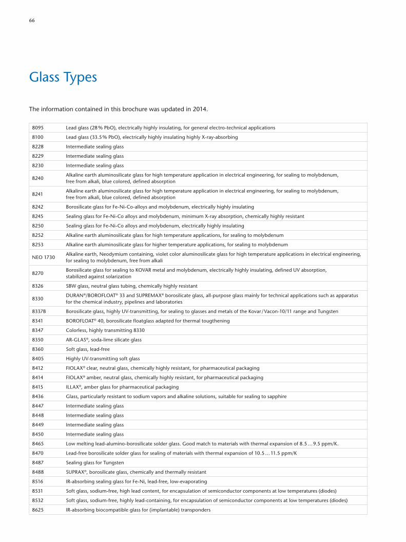
The information contained in this brochure was updated in 2014.
8095 Lead glass (28 % PbO), electrically highly insulating, for general electrotechnical applications
8100 Lead glass (33.5 % PbO), electrically highly insulating highly Xrayabsorbing
8228 Intermediate sealing glass
8229 Intermediate sealing glass
8230 Intermediate sealing glass
8240Alkaline earth aluminosilicate glass for high temperature application in electrical engineering, for sealing to molybdenum, free from alkali, blue colored, defined absorption
8241Alkaline earth aluminosilicate glass for high temperature application in electrical engineering, for sealing to molybdenum, free from alkali, blue colored, defined absorption
8242 Borosilicate glass for FeNiCoalloys and molybdenum, electrically highly insulating
8245 Sealing glass for FeNiCo alloys and molybdenum, minimum Xray absorption, chemically highly resistant
8250 Sealing glass for FeNiCo alloys and molybdenum, electrically highly insulating
8252 Alkaline earth aluminosilicate glass for high temperature applications, for sealing to molybdenum
8253 Alkaline earth aluminosilicate glass for higher temperature applications, for sealing to molybdenum
NEO 1730 Alkaline earth, Neodymium containing, violet color aluminosilicate glass for high temperature applications in electrical engineering, for sealing to molybdenum, free from alkali
8270Borosilicate glass for sealing to KOVAR metal and molybdenum, electrically highly insulating, defined UV absorption, stabilized against solarization
8326 SBW glass, neutral glass tubing, chemically highly resistant
8330 DURAN®/BOROFLOAT® 33 and SUPREMAX® borosilicate glass, allpurpose glass mainly for technical applications such as apparatus for the chemical industry, pipelines and laboratories
8337B Borosilicate glass, highly UVtransmitting, for sealing to glasses and metals of the Kovar / Vacon10/11 range and Tungsten
8341 BOROFLOAT® 40, borosilicate floatglass adapted for thermal tougthening
8347 Colorless, highly transmitting 8330
8350 ARGLAS®, sodalime silicate glass
8360 Soft glass, leadfree
8405 Highly UVtransmitting soft glass
8412 FIOLAX® clear, neutral glass, chemically highly resistant, for pharmaceutical packaging
8414 FIOLAX® amber, neutral glass, chemically highly resistant, for pharmaceutical packaging
8415 ILLAX®, amber glass for pharmaceutical packaging
8436 Glass, particularly resistant to sodium vapors and alkaline solutions, suitable for sealing to sapphire
8447 Intermediate sealing glass
8448 Intermediate sealing glass
8449 Intermediate sealing glass
8450 Intermediate sealing glass
8465 Low melting leadaluminoborosilicate solder glass. Good match to materials with thermal expansion of 8.5 … 9.5 ppm/K.
8470 Leadfree borosilicate solder glass for sealing of materials with thermal expansion of 10.5 … 11.5 ppm/K
8487 Sealing glass for Tungsten
8488 SUPRAX®, borosilicate glass, chemically and thermally resistant
8516 IRabsorbing sealing glass for FeNi, leadfree, lowevaporating
8531 Soft glass, sodiumfree, high lead content, for encapsulation of semiconductor components at low temperatures (diodes)
8532 Soft glass, sodiumfree, highly leadcontaining, for encapsulation of semiconductor components at low temperatures (diodes)
8625 IRabsorbing biocompatible glass for (implantable) transponders
Glass Types
66
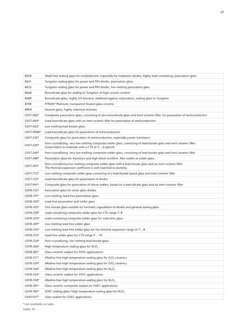
8650 Alkalifree sealing glass for molybdenum, especially for implosion diodes, highly leadcontaining, passivation glass
8651 Tungsten sealing glass for power and PIN diodes, passivation glass
8652 Tungsten sealing glass for power and PIN diodes, low melting passivation glass
8660 Borosilicate glass for sealing to Tungsten of high cesium content
8689 Borosilicate glass, highly UVblocked, stabilized against solarization, sealing glass to Tungsten
8708 PYRAN® Platinum, transparent floated glassceramic
8800 Neutral glass, highly chemical resistant
G017002* Composite passivation glass, consisting of zincborosilicate glass and inert ceramic filler, for passivation of semiconductors
G017004* Leadborosilicate glass with an inert ceramic filler for passivation of semiconductors
G017052* Low melting leadborate glass
G017096R* Leadborosilicate glass for passivation of semiconductors
G017230* Composite glass for passivation of semiconductors, especially power transistors
G017339*Noncrystallizing, very low melting composite solder glass, consisting of leadborate glass and inert ceramic filler. Good match to materials with a CTE of 5 … 6 ppm/K.
G017340* Noncrystallizing, very low melting composite solder glass, consisting of leadborate glass and inert ceramic filler
G017388* Passiviation glass for thyristors and high block rectifiers. Also usable as solder glass.
G017393*Noncrystallizing low melting composite solder glass with a leadborate glass and an inert ceramic filler The thermal expansion coefficient is well matched to alumina.
G017712* Low melting composite solder glass consisting of a leadborate based glass and inert ceramic filler
G017725* Leadborosilicate glass for passivation of diodes
G017997* Composite glass for passivation of silicon wafers, based on a leadsilicate glass and an inert ceramic filler
G018133* Passivation glass for sinter glass diodes
G018197* Low melting, leadfree passiviation glass
G018200* Leadfree passivation and solder glass
G018205* Zincborate glass suitable for hermetic capsulation of diodes and general sealing glass
G018228* Leadcontaining composite solder glass for CTE range 7– 8
G018229* Leadcontaining composite solder glass for sodalime glass
G018249* Low melting leadfree solder glass
G018250* Low melting leadfree solder glass for the thermal expansion range of 7 … 8
G018255* Leadfree solder glass for CTE range 9 … 10
G018256* Noncrystallizing, low melting leadborate glass
G018266* High temperature sealing glass for Al2O3
G018281* Glassceramic sealant for SOFC applications
G018311* Alkalinefree high temperature sealing glass for ZrO2 ceramics
G018339* Alkalinefree high temperature sealing glass for ZrO2 ceramics
G018346* Alkalinefree high temperature sealing glass for Al2O3
G018354* Glassceramic sealant for SOFC applications
G018358* Alkalinefree high temperature sealing glass for Al2O3
G018381* Glassceramic composite sealant for SOFC applications
G018385* SOFC sealing glass / High temperature sealing glass for Al2O3
GM31107* Glass sealant for SOFC applications
* not available as tube.
Table 19.
67

1 2 3 4 5 6 7 8 9 10 11 12 13 14 15 16
Glass no. α20/300 Transforma-tion tem-perature Tg
Glass temperature at viscosities Density at 25 °C
Firing conditions Young’s modulus
Poisson’s- ratio
Heat con- ductivity λ at 90 °C
tk100 Logarithm of the electric volume resistance in Ω cm at
Dielectric properties for 1 MHz at 25 °C
Refractive index nd (λd = 587.6 nm)
Stress- optical coefficient K
Classes of chemical stability
Glass no.
1013 dPa · s 107,6 dPa · s 104 dPa · s Firing Temp Dwell time
[10–6/K] [°C] [°C] [°C] [°C] [g/cm3] °C min[103N/ mm2] µ [W/(m · K)] [°C] 250 °C 350 °C εr
tanδ [10–4] [10–6 mm2/N] Water Acid
Alkaline solution
8095 9.1 430 435 630 982 3.01 – – 60 0.22 0.9 330 9.6 7.6 6.6 11 1.556 3.1 3 2 3 8095
8100 9.6 465 465 655 960 3.28 – – – – – – – – – – 1.595 – 3 – – 8100
8228 1.3 700 726 1200 1705 2.15 – – – – – 355 – – – – – – – – – 8228
8229 2.0 630 637 930 1480 2.17 – – – – – 350 – – – – – – – – – 8229
8230 2.7 570 592 915 1520 2.19 – – – – – 257 – – – – – – – – – 8230
8240 4.7 790 795 1005 1305 2.67 – – 83 0.23 1.1 630 13.0 11.0 6.6 15 1.546 2.7 – – – 8240
8241 4.7 790 795 1005 1305 2.67 – – 83 0.23 1.1 630 13.0 11.0 6.6 15 1.546 2.7 – – – 8241
8242 4.8 470 480 720 1120 2.27 – – 57.2 0.21 – – – – – – 1.480 – 2 – – 8242
8245 5.1 505 515 720 1040 2.31 – – 68 0.22 1.2 215 7.4 5.9 5.7 80 1.488 3.8 3 4 3 8245
8250 5.0 490 500 720 1055 2.28 – – 64 0.21 1.2 375 10 8.3 4.9 22 1.487 3.6 3 4 3 8250
8252 4.6 720 725 935 1240 2.63 – – 81 0.24 1.1 660 14.3 12 6.1 11 1.538 2.8 1 3 2 8252
8253 4.7 790 795 1005 1305 2.7 – – 83 0.23 1.1 630 13 11 6.6 15 1.547 2.7 1 2 2 8253
NEO 1730 4.5 725 725 935 1210 2.67 – – – – – – – – – – 1.548 – 1 3 2 NEO 1730
8270 5.0 490 505 705 1045 2.27 – – 64 0.21 1.2 377 10.3 8.4 5.3 127 1.487 3.6 3 4 3 8270
8326 6.6 565 570 770 1125 2.45 – – 75 0.20 1.2 210 7.3 6.0 6.4 65 1.506 2.8 1 1 2 8326
8330 3.3 525 560 825 1260 2.23 – – 63 0.20 1.2 250 8.0 6.5 4.6 37 1.473 4.0 1 1 2 8330
8337B 4.1 440 465 705 1085 2.22 – – 51 0.22 1.0 315 9.2 7.5 4.7 22 1.476 4.1 3 4 3 8337B
8341 4.04 577 600 840 1277 2.28 – – 68 0.20 1.2 – – – – – 1.479 – 1 1 2 8341
8347 3.3 525 560 825 1260 2.23 – – 63 0.20 1.2 250 8.0 6.5 4.6 37 1.473 4.0 1 1 2 8347
8350 9.1 525 530 720 1040 2.50 – – 73 0.22 1.1 200 7.2 5.7 7.2 70 1.514 2.7 3 1 2 8350
8360 9.1 465 470 575 745 2.66 – – 85 0.238 – 275 8.5 6.7 7.3 24 1.566 2.9 3 4 3 8360
8405 9.7 460 470 665 1000 2.51 – – 65 0.21 1.0 280 8.5 6.9 6.5 45 1.505 2.8 5 3 2 8405
8412 4.9 565 565 785 1165 2.34 – – 73 0.20 1.2 215 7.4 6.0 5.7 80 1.492 3.4 1 1 2 8412
8414 5.4 560 560 770 1155 2.42 – – 71 0.19 1.2 200 7.1 5.6 6.3 107 1.523 2.2 1 2 2 8414
8415 7.8 535 540 720 1050 2.50 – – 74 0.21 1.1 180 6.7 5.3 7.1 113 1.521 3.2 2 2 2 8415
8436 6.6 624 – – 1085 2.785 – – – – – – – – – – – – 1 2–3 1 8436
8447 4.8 480 505 720 1035 2.27 – – – – – 271 – – – – – – – – – 8447
8448 3.7 510 560 800 1205 2.25 – – – – – 263 – – – – – – – – – 8448
8449 4.5 535 550 785 1150 2.29 – – – – – 348 – – – – – – – – – 8449
8450 5.4 570 575 778 1130 2.44 – – – – – 200 – – – – – – – – – 8450
8454 6.4 565 575 750 1070 2.49 – – – – – 210 – – – – – – – – – 8454
8455 6.7 565 – 740 1030 2.44 – – – – – – – – – – – – – – – 8455
8456 7.4 445 – 685 1145 2.49 – – – – – – – – – – – – – – – 8456
8465 8.2 385 – – – 5.4 520 30 – – – – – – – – – – – – – 8465
8470 10.0 440 – 570 748 2.80 – – – – – 295 – – – – – 3.7 1 1 2 8470
8487 3.9 525 560 775 1135 2.25 – – 66 0.20 1.2 300 8.3 6.9 4.9 36 1.479 3.6 4 3 3 8487
8488 4.3 545 560 800 1250 2.30 – – 67 0.20 1.2 200 7.1 5.8 5.4 96 1.484 3.2 1 1 2 8488
8516 8.9 447 445 646 990 2.56 – – 72 0.21 1.1 250 8.1 6.4 6.5 25 1.516 3.0 3 1 2 8516
8531 9.1 435 430 585 820 4.31 – – 52 0.24 0.7 450 11 9.8 9.5 9 1.700 2.2 1 4 3 8531
8532 8.7 435 430 560 760 4.46 – – 56 0.24 0.7 440 11 9.4 10.2 9 1.724 1.7 1 4 3 8532
8625 9.15 514 520 703 1023 2.52 – – 73 0.22 1.1 210 7.2 5.8 7.1 68 1.525 – 3 1 2 8625
8650 5.1 475 475 625 885 3.57 – – 62 0.23 0.5 128 13.5 11.6 7.6 11 1.618 2.8 1 4 3 8650
8651 4.4 549 540 736 1034 2.91 – – 59 0.24 0.9 – 11.2 10.0 6.0 31 1.552 3.6 1 4 3 8651
8652 4.5 495 490 638 900 3.18 – – 58 0.25 0.9 – – – 6.9 35 1.589 3.4 1 4 3 8652
Glasses for the Chemical Industry and Electrical Engineering · Sealing Glasses
68

1 2 3 4 5 6 7 8 9 10 11 12 13 14 15 16
Glass no. α20/300 Transforma-tion tem-perature Tg
Glass temperature at viscosities Density at 25 °C
Firing conditions Young’s modulus
Poisson’s- ratio
Heat con- ductivity λ at 90 °C
tk100 Logarithm of the electric volume resistance in Ω cm at
Dielectric properties for 1 MHz at 25 °C
Refractive index nd (λd = 587.6 nm)
Stress- optical coefficient K
Classes of chemical stability
Glass no.
1013 dPa · s 107,6 dPa · s 104 dPa · s Firing Temp Dwell time
[10–6/K] [°C] [°C] [°C] [°C] [g/cm3] °C min[103N/ mm2] µ [W/(m · K)] [°C] 250 °C 350 °C εr
tanδ [10–4] [10–6 mm2/N] Water Acid
Alkaline solution
8095 9.1 430 435 630 982 3.01 – – 60 0.22 0.9 330 9.6 7.6 6.6 11 1.556 3.1 3 2 3 8095
8100 9.6 465 465 655 960 3.28 – – – – – – – – – – 1.595 – 3 – – 8100
8228 1.3 700 726 1200 1705 2.15 – – – – – 355 – – – – – – – – – 8228
8229 2.0 630 637 930 1480 2.17 – – – – – 350 – – – – – – – – – 8229
8230 2.7 570 592 915 1520 2.19 – – – – – 257 – – – – – – – – – 8230
8240 4.7 790 795 1005 1305 2.67 – – 83 0.23 1.1 630 13.0 11.0 6.6 15 1.546 2.7 – – – 8240
8241 4.7 790 795 1005 1305 2.67 – – 83 0.23 1.1 630 13.0 11.0 6.6 15 1.546 2.7 – – – 8241
8242 4.8 470 480 720 1120 2.27 – – 57.2 0.21 – – – – – – 1.480 – 2 – – 8242
8245 5.1 505 515 720 1040 2.31 – – 68 0.22 1.2 215 7.4 5.9 5.7 80 1.488 3.8 3 4 3 8245
8250 5.0 490 500 720 1055 2.28 – – 64 0.21 1.2 375 10 8.3 4.9 22 1.487 3.6 3 4 3 8250
8252 4.6 720 725 935 1240 2.63 – – 81 0.24 1.1 660 14.3 12 6.1 11 1.538 2.8 1 3 2 8252
8253 4.7 790 795 1005 1305 2.7 – – 83 0.23 1.1 630 13 11 6.6 15 1.547 2.7 1 2 2 8253
NEO 1730 4.5 725 725 935 1210 2.67 – – – – – – – – – – 1.548 – 1 3 2 NEO 1730
8270 5.0 490 505 705 1045 2.27 – – 64 0.21 1.2 377 10.3 8.4 5.3 127 1.487 3.6 3 4 3 8270
8326 6.6 565 570 770 1125 2.45 – – 75 0.20 1.2 210 7.3 6.0 6.4 65 1.506 2.8 1 1 2 8326
8330 3.3 525 560 825 1260 2.23 – – 63 0.20 1.2 250 8.0 6.5 4.6 37 1.473 4.0 1 1 2 8330
8337B 4.1 440 465 705 1085 2.22 – – 51 0.22 1.0 315 9.2 7.5 4.7 22 1.476 4.1 3 4 3 8337B
8341 4.04 577 600 840 1277 2.28 – – 68 0.20 1.2 – – – – – 1.479 – 1 1 2 8341
8347 3.3 525 560 825 1260 2.23 – – 63 0.20 1.2 250 8.0 6.5 4.6 37 1.473 4.0 1 1 2 8347
8350 9.1 525 530 720 1040 2.50 – – 73 0.22 1.1 200 7.2 5.7 7.2 70 1.514 2.7 3 1 2 8350
8360 9.1 465 470 575 745 2.66 – – 85 0.238 – 275 8.5 6.7 7.3 24 1.566 2.9 3 4 3 8360
8405 9.7 460 470 665 1000 2.51 – – 65 0.21 1.0 280 8.5 6.9 6.5 45 1.505 2.8 5 3 2 8405
8412 4.9 565 565 785 1165 2.34 – – 73 0.20 1.2 215 7.4 6.0 5.7 80 1.492 3.4 1 1 2 8412
8414 5.4 560 560 770 1155 2.42 – – 71 0.19 1.2 200 7.1 5.6 6.3 107 1.523 2.2 1 2 2 8414
8415 7.8 535 540 720 1050 2.50 – – 74 0.21 1.1 180 6.7 5.3 7.1 113 1.521 3.2 2 2 2 8415
8436 6.6 624 – – 1085 2.785 – – – – – – – – – – – – 1 2–3 1 8436
8447 4.8 480 505 720 1035 2.27 – – – – – 271 – – – – – – – – – 8447
8448 3.7 510 560 800 1205 2.25 – – – – – 263 – – – – – – – – – 8448
8449 4.5 535 550 785 1150 2.29 – – – – – 348 – – – – – – – – – 8449
8450 5.4 570 575 778 1130 2.44 – – – – – 200 – – – – – – – – – 8450
8454 6.4 565 575 750 1070 2.49 – – – – – 210 – – – – – – – – – 8454
8455 6.7 565 – 740 1030 2.44 – – – – – – – – – – – – – – – 8455
8456 7.4 445 – 685 1145 2.49 – – – – – – – – – – – – – – – 8456
8465 8.2 385 – – – 5.4 520 30 – – – – – – – – – – – – – 8465
8470 10.0 440 – 570 748 2.80 – – – – – 295 – – – – – 3.7 1 1 2 8470
8487 3.9 525 560 775 1135 2.25 – – 66 0.20 1.2 300 8.3 6.9 4.9 36 1.479 3.6 4 3 3 8487
8488 4.3 545 560 800 1250 2.30 – – 67 0.20 1.2 200 7.1 5.8 5.4 96 1.484 3.2 1 1 2 8488
8516 8.9 447 445 646 990 2.56 – – 72 0.21 1.1 250 8.1 6.4 6.5 25 1.516 3.0 3 1 2 8516
8531 9.1 435 430 585 820 4.31 – – 52 0.24 0.7 450 11 9.8 9.5 9 1.700 2.2 1 4 3 8531
8532 8.7 435 430 560 760 4.46 – – 56 0.24 0.7 440 11 9.4 10.2 9 1.724 1.7 1 4 3 8532
8625 9.15 514 520 703 1023 2.52 – – 73 0.22 1.1 210 7.2 5.8 7.1 68 1.525 – 3 1 2 8625
8650 5.1 475 475 625 885 3.57 – – 62 0.23 0.5 128 13.5 11.6 7.6 11 1.618 2.8 1 4 3 8650
8651 4.4 549 540 736 1034 2.91 – – 59 0.24 0.9 – 11.2 10.0 6.0 31 1.552 3.6 1 4 3 8651
8652 4.5 495 490 638 900 3.18 – – 58 0.25 0.9 – – – 6.9 35 1.589 3.4 1 4 3 8652
Glasses for the Chemical Industry and Electrical Engineering · Sealing Glasses
69

1 2 3 4 5 6 7 8 9 10 11 12 13 14 15 16
Glass no. α20/300 Transforma-tion tem-perature Tg
Glass temperature at viscosities Density at 25 °C
Firing conditions Young’s modulus
Poisson’s- ratio
Heat con- ductivity λ at 90 °C
tk100 Logarithm of the electric volume resistance in Ω cm at
Dielectric properties for 1 MHz at 25 °C
Refractive index nd (λd = 587.6 nm)
Stress- optical coefficient K
Classes of chemical stability
Glass no.
1013 dPa · s 107,6 dPa · s 104 dPa · s Firing Temp Dwell time
[10–6/K] [°C] [°C] [°C] [°C] [g/cm3] °C min[103N/ mm2] µ [W/(m · K)] [°C] 250 °C 350 °C εr
tanδ [10–4] [10–6 mm2/N] Water Acid
Alkaline solution
8660 4.0 555 549 830 1215 2.44 – – – – – 550 12.7 10.7 – – 1.486 – 3 3 3 8660
8689 3.8 515 565 770 1110 2.27 – – 65 0.2 1.2 314 9.1 7.5 5.0 20 1.498 3.9 3 3 3 8689
8708 –0.36 – 885 – – 2.5018 – – 92 0.254 1.65 175 6.6 5.2 7.6 21.8 1.53694 – 1 3 1 8708
8800 5.5 565 570 790 1175 2.34 – – 73 – – 191 7.0 5.7 5.9 143 1.490 4.6 1 1 2 8800
G017002 3.7 545 – 640 – 3.25 700 10 – – – – – – 6.8 37 – – – – – G017002
G017004 4.1 440 – 660 – 3.22 740 5 – – – – – – – – – – – – – G017004
G017052 11.7 308 – 347 – 6.65 410 15 43 – – – – – – – – – – – – G017052
G017096R 4.8 456 – 650 – 3.54 680 5 – – – – – – – – – – – – – G017096R
G017230 4.2 440 – 650 – 3.45 700 4 62 0.224 – – – – – – – – – – – G017230
G017339 4.7 325 – 415 – 4.3 510 30 – – – – – – – – – – – – – G017339
G017340 7.0 315 – 360 – 4.8 420 15 60 0.281 – – – – – – – – – – – G017340
G017388 3.6 550 – 645 – 3.4 700 5 – – – – – – – – – – – – – G017388
G017393 6.5 320 – 370 – 4.8 420 15 58 – – – – – – – – – – – – G017393
G017712 5.3 375 – – – 4.0 510 10 – – – – – – – – – – – – – G017712
G017725 4.9 468 – 620 874 3.59 670 10 58 0.223 – – – – – – – – – – – G017725
G017997 4.4 485 – – – 3.45 760 20 – – – – – – – – – – – – – G017997
G018133 4.8 463 – – – 3.47 690 30 60 0.22 – – – – – – – – – – – G018133
G018197 4.4 557 – – – 3.76 675 10 – – – – – – – – – – – – – G018197
G018200 4.6 557 – – – 3.63 665 10 – – – – – – – – – – – – – G018200
G018205 4.45 541 – 632 – 3.83 690 10 – – – – – – – – – – – – – G018205
G018228 7.6 311 – – – 5.0 400 15 – – – – – – – – – – – – – G018228
G018229 8.3 310 – – – 5.44 400 15 – – – – – – – – – – – – – G018229
G018249 10.1 365 – – – 7.13 500 10 68 0.307 – – – – – – – – – – – G018249
G018250 7.0 380 – – – 5.7 510 10 – – – – – – – – – – – – – G018250
G018255 9.4 396 – – – 6.71 520 15 76 0.237 – – – – – – – – – – – G018255
G018256 9.2 316 – – – 5.79 420 15 – – – – – – – – – – – – – G018256
G018266 6.9 (glassy) 585 – 673 780 4.55 770 15 111 0.304 – – – – – – – – – – – G018266
G018281 12 652 656 864 1196 2.72 960 30 – – – – – – – – – – – – – G018281
G018311 9.1 (glassy) 9.9 (p.c.)**
622 690 – 873 3.8 850 30 – – – – – – – – – – – – – G018311
G018339 9.2 (p.c.)** 627 – – – – 990 15 – – – – – – – – – – – – – G018339
G018346 7.3 (glassy) 720 – – – – 1270 15 – – – – – – – – – – – – – G018346
G018354 9.2 643 – 753 908 3.9 850 30 – – – – – – – – – – – – – G018354
G018358 8.5 (glassy) 8.8 (p.c.)**
658 – – – 3.24 940 15 – – – – – – – – – – – – – G018358
G018381 4.6 (glassy) 12 (a.c.)**
652 – – – 2.3 900 60 – – – – – – – – – – – – – G018381
G018385 8.4 (p.c.)** 992** 696 808 862 3.14 950 30 123** – – – – – – – – – – – – G018385
GM31107 10.0 (a.c.)** 532 – 632 750 3.7 700 30 – – – – – – – – – – – – – GM31107
** partially crystalline
Table 20. Characteristic values of technical glasses
70

1 2 3 4 5 6 7 8 9 10 11 12 13 14 15 16
Glass no. α20/300 Transforma-tion tem-perature Tg
Glass temperature at viscosities Density at 25 °C
Firing conditions Young’s modulus
Poisson’s- ratio
Heat con- ductivity λ at 90 °C
tk100 Logarithm of the electric volume resistance in Ω cm at
Dielectric properties for 1 MHz at 25 °C
Refractive index nd (λd = 587.6 nm)
Stress- optical coefficient K
Classes of chemical stability
Glass no.
1013 dPa · s 107,6 dPa · s 104 dPa · s Firing Temp Dwell time
[10–6/K] [°C] [°C] [°C] [°C] [g/cm3] °C min[103N/ mm2] µ [W/(m · K)] [°C] 250 °C 350 °C εr
tanδ [10–4] [10–6 mm2/N] Water Acid
Alkaline solution
8660 4.0 555 549 830 1215 2.44 – – – – – 550 12.7 10.7 – – 1.486 – 3 3 3 8660
8689 3.8 515 565 770 1110 2.27 – – 65 0.2 1.2 314 9.1 7.5 5.0 20 1.498 3.9 3 3 3 8689
8708 –0.36 – 885 – – 2.5018 – – 92 0.254 1.65 175 6.6 5.2 7.6 21.8 1.53694 – 1 3 1 8708
8800 5.5 565 570 790 1175 2.34 – – 73 – – 191 7.0 5.7 5.9 143 1.490 4.6 1 1 2 8800
G017002 3.7 545 – 640 – 3.25 700 10 – – – – – – 6.8 37 – – – – – G017002
G017004 4.1 440 – 660 – 3.22 740 5 – – – – – – – – – – – – – G017004
G017052 11.7 308 – 347 – 6.65 410 15 43 – – – – – – – – – – – – G017052
G017096R 4.8 456 – 650 – 3.54 680 5 – – – – – – – – – – – – – G017096R
G017230 4.2 440 – 650 – 3.45 700 4 62 0.224 – – – – – – – – – – – G017230
G017339 4.7 325 – 415 – 4.3 510 30 – – – – – – – – – – – – – G017339
G017340 7.0 315 – 360 – 4.8 420 15 60 0.281 – – – – – – – – – – – G017340
G017388 3.6 550 – 645 – 3.4 700 5 – – – – – – – – – – – – – G017388
G017393 6.5 320 – 370 – 4.8 420 15 58 – – – – – – – – – – – – G017393
G017712 5.3 375 – – – 4.0 510 10 – – – – – – – – – – – – – G017712
G017725 4.9 468 – 620 874 3.59 670 10 58 0.223 – – – – – – – – – – – G017725
G017997 4.4 485 – – – 3.45 760 20 – – – – – – – – – – – – – G017997
G018133 4.8 463 – – – 3.47 690 30 60 0.22 – – – – – – – – – – – G018133
G018197 4.4 557 – – – 3.76 675 10 – – – – – – – – – – – – – G018197
G018200 4.6 557 – – – 3.63 665 10 – – – – – – – – – – – – – G018200
G018205 4.45 541 – 632 – 3.83 690 10 – – – – – – – – – – – – – G018205
G018228 7.6 311 – – – 5.0 400 15 – – – – – – – – – – – – – G018228
G018229 8.3 310 – – – 5.44 400 15 – – – – – – – – – – – – – G018229
G018249 10.1 365 – – – 7.13 500 10 68 0.307 – – – – – – – – – – – G018249
G018250 7.0 380 – – – 5.7 510 10 – – – – – – – – – – – – – G018250
G018255 9.4 396 – – – 6.71 520 15 76 0.237 – – – – – – – – – – – G018255
G018256 9.2 316 – – – 5.79 420 15 – – – – – – – – – – – – – G018256
G018266 6.9 (glassy) 585 – 673 780 4.55 770 15 111 0.304 – – – – – – – – – – – G018266
G018281 12 652 656 864 1196 2.72 960 30 – – – – – – – – – – – – – G018281
G018311 9.1 (glassy) 9.9 (p.c.)**
622 690 – 873 3.8 850 30 – – – – – – – – – – – – – G018311
G018339 9.2 (p.c.)** 627 – – – – 990 15 – – – – – – – – – – – – – G018339
G018346 7.3 (glassy) 720 – – – – 1270 15 – – – – – – – – – – – – – G018346
G018354 9.2 643 – 753 908 3.9 850 30 – – – – – – – – – – – – – G018354
G018358 8.5 (glassy) 8.8 (p.c.)**
658 – – – 3.24 940 15 – – – – – – – – – – – – – G018358
G018381 4.6 (glassy) 12 (a.c.)**
652 – – – 2.3 900 60 – – – – – – – – – – – – – G018381
G018385 8.4 (p.c.)** 992** 696 808 862 3.14 950 30 123** – – – – – – – – – – – – G018385
GM31107 10.0 (a.c.)** 532 – 632 750 3.7 700 30 – – – – – – – – – – – – – GM31107
** partially crystalline
Table 20. Characteristic values of technical glasses
71
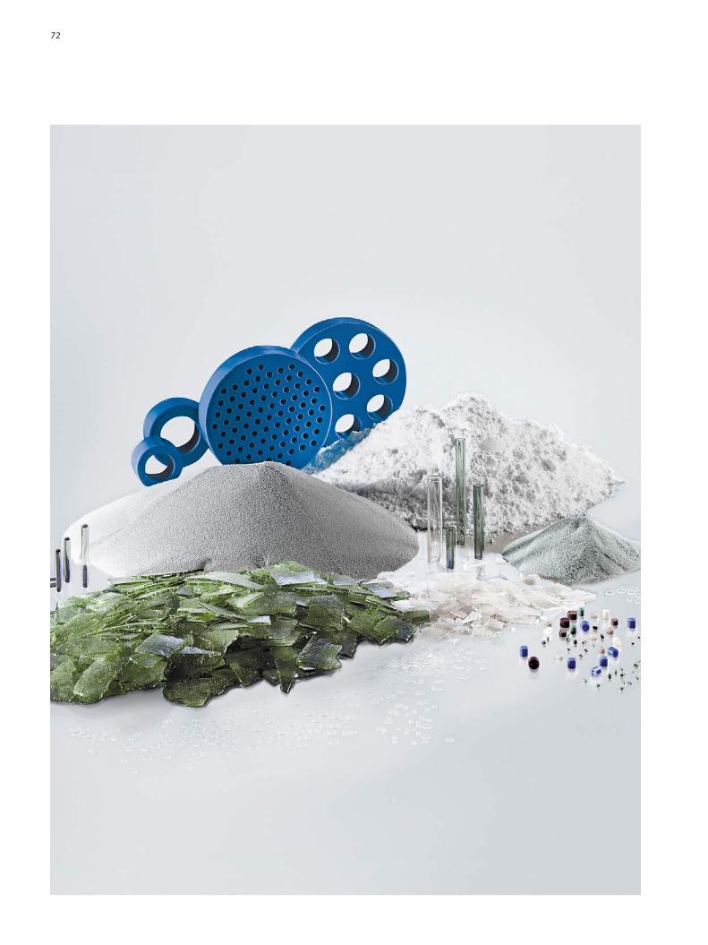
72

Advanced OpticsSCHOTT AGHattenbergstrasse 1055122 MainzGermanyPhone +49 (0)6131/661812Fax +49 (0)3641/2888[email protected]/advanced_optics
Electronic PackagingSCHOTT AGChristophDornerStrasse 2984028 LandshutGermanyPhone +49 (0)871/8260Fax +49 (0)3641/2888[email protected]/epackaging
Flat GlassSCHOTT AGHattenbergstrasse 1055122 MainzGermanyPhone +49 (0)6131/663373Fax +49 (0)3641/2888[email protected]/flatglass
SCHOTT AGResearch and DevelopmentHattenbergstrasse 1055122 MainzGermanyPhone +49 (0)6131/667616Fax +49 (0)3641/28889123www.schott.com/rd
Home TechSCHOTT AGHattenbergstrasse 1055122 MainzGermanyPhone +49 (0)6131/660Fax +49 (0)6131/662000www.schott.com/hometech
TubingSCHOTT AGErichSchottStrasse 1495666 MitterteichGermanyPhone +49 (0)9633/800Fax +49 (0)9633/80[email protected]/tubing
SCHOTT Technical Glass Solutions GmbHOttoSchottStrasse 1307745 JenaGermanyPhone +49 (0)3641/6814686Fax +49 (0)3641/2888[email protected]/borofloat
Your Contacts
73

H. Bach and D. Krause (Eds.): SCHOTT Series on Glass and Glass Ceramics, SpringerVerlag, Berlin, Heidelberg The Properties of Optical Glass (1998, 2nd printing)Low Thermal Expansion Glass Ceramics (1995)Thin Films on Glass (1997)Analysis of the Composition and Structure of Glass and Glass Ceramics (1999)Electrochemistry of Glasses and Glass Melts (2000)Mathematical Simulation in Glass Technology (2002)
M. BenzZauner, H.A. Schaeffer (Eds.): Flachglas, Deutsches Museum Verlag, München, 2007
K. Binder, W. Kob: Glass Materials and Disordered Solids – An Introduction to their Statistical Mechanics, World Sci. Pub., 2006
European Pharmacopeia, Vol. 2, Europ. Pharmacop. Com mis sion Strasbourg 1971, pp. 65 – 71
I. Gutzow, J. Schmelzer: The Vitreous State/Thermo dy na mics, Structure, Rheology and Crystallization, SpringerVerlag, Berlin, Heidelberg 1995
D.G. Holloway: The Physical Properties of Glass, Wykeham Publications, London 1973
F. Kerkhof: Bruchvorgänge in Gläsern, Verlag der Deut schen Glastechnischen Gesellschaft, Frankfurt a. M. 1970
W.D. Kingery, H.K. Bowen, D.R. Uhlmann: Introduction to Ceramics, John Wiley and Sons, New York 1995
G.W. McLellan, E.B. Shand: Glass Engineering Hand book, McGrawHill Book Company Inc., New York 1984
H.G. Pfaender (Ed.): Guide to Glass, Chapman & Hall, London 1996
H.A. Schaeffer, M. BenzZauner (Eds.): Spezialglas,Deutsches Museum Verlag, München 2009
H.A. Schaeffer, R. Langfeld, M. BenzZauner (Eds.):Werkstoff Glas, Deutsches Museum Verlag, München 2012
H.A. Schaeffer, R. LangfeldWerkstoff Glas – Alter Werkstoff mit großer ZukunftReihe Technik im Fokus, Springer Verlag, Heidelberg 2014
H. Scholze:Glass. Nature, Structure and PropertiesSpringerVerlag, Berlin, Heidelberg 1994
A.K. Varshneya:Fundamentals of Inorganic Glasses,The Society of Glass Technology, Sheffield, 2006
W. Vogel: Glass Chemistry, SpringerVerlag, Berlin, Heidelberg 1994
Literature
74

75
SCHOTT AGResearch and Development Hattenbergstrasse 1055122 MainzGermanyPhone +49 (0)6131/667616Fax +49 (0)3641/28889123www.schott.com/rd
40024 ENGLISH 05141.0 kn/E&B Printed in Germany