Embed Size (px)
Citation preview
Technical data sheet P6..W..EV-BAC
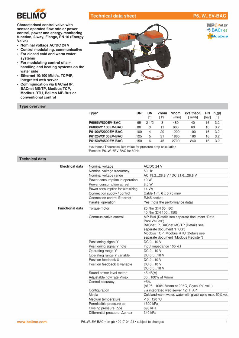
Characterised control valve with sensor-operated flow rate or power control, power and energy-monitoring function, 2-way, Flange, PN 16 (Energy Valve)• Nominal voltage AC/DC 24 V• Control modulating, communicative• For closed cold and warm water
systems• For modulating control of air-
handling and heating systems on thewater side
• Ethernet 10/100 Mbit/s, TCP/IP,integrated web server
• Communication via BACnet IP,BACnet MS/TP, Modbus TCP,Modbus RTU, Belimo MP-Bus orconventional control
Type overview
Type* DN[ ]
DN[“]
Vnom[ l/s]
Vnom[ l/min]
kvs theor.[ m³/h]
PN[bar]
n(gl)[ ]
P6065W800EV-BAC 65 2 1/2 8 480 40 16 3.2P6080W1100EV-BAC 80 3 11 660 60 16 3.2P6100W2000EV-BAC 100 4 20 1200 100 16 3.2P6125W3100EV-BAC 125 5 31 1860 160 16 3.2P6150W4500EV-BAC 150 6 45 2700 240 16 3.2
kvs theor.: Theoretical kvs value for pressure drop calculation
Technical data
Electrical data Nominal voltage AC/DC 24 VNominal voltage frequency 50 HzNominal voltage range AC 19.2...28.8 V / DC 21.6...28.8 VPower consumption in operation 10 WPower consumption at rest 8.5 WPower consumption for wire sizing 14 VAConnection supply / control Cable 1 m, 6 x 0.75 mm²Connection control Ethernet RJ45 socketParallel operation Yes (note the performance data)
Functional data Torque motor 20 Nm (DN 65...80)40 Nm (DN 100...150)
Communicative control MP-Bus (Details see separate document “Data-Pool Values”)BACnet IP, BACnet MS/TP (Details see seperate document “PICS”)Modbus TCP, Modbus RTU (Details see separate document “Modbus Register”)
Positioning signal Y DC 0...10 VPositioning signal Y note Input impedance 100 kΩOperating range Y DC 2...10 VOperating range Y variable DC 0.5...10 VPosition feedback U DC 2...10 VPosition feedback U variable DC 0...10 V
DC 0.5...10 VSound power level motor 45 dB(A)Adjustable flow rate Vmax 30...100% of VnomControl accuracy ±5%
(of 25...100% Vnom at 20°C, Glycol 0% vol. )Configuration via integrated web server / ZTH APMedia Cold and warm water, water with glycol up to max. 50% vol.Medium temperature -10...120°CPermissible pressure ps 1600 kPaClosing pressure ∆ps 690 kPaDifferential pressure ∆pmax 340 kPa
www.belimo.com P6..W..EV-BAC • en-gb • 2017-04-24 • subject to changes 1
*Remark: P6..W..6EV-BAC for 60Hz.
Functional data Flow characteristic equal percentage (VDI/VDE 2178), optimised in the opening range (switchable to linear)
Leakage rate Leakage rate A, air-bubble-tight (EN 12266-1)Pipe connector Flange PN 16 according to EN 1092-2Installation position Upright to horizontal (in relation to the stem)Maintenance Maintenance-freeManual override with push-button, can be locked
Flow measurement Measuring principle Magnetic inductive volumetric flow measurement
Measuring accuracy ±2%(of 25...100% Vnom at 20°C, Glycol 0% vol. )
Min. flow measurement 1.25% of Vnom
Temperature measurement Measuring accuracy of the absolute temperature
PT1000 EN60751 Class B(For 1/3 DIN PT1000 EN60751 Class AA, referto accessories EV-RT-100-AA)
Measuring accuracy of temperature difference
±0.18°C @ ∆T = 10°C
Resolution 0.05°C
Safety Protection class IEC/EN III Safety Extra-Low Voltage (SELV)Degree of protection IEC/EN IP54 (for use of protective cap or grommet for
RJ45 socket)EMC CE according to 2014/30/EUMode of operation Type 1Rated impulse voltage supply / control 0.8 kVControl pollution degree 3Ambient temperature -10...50°CNon-operating temperature -20...80°CAmbient humidity 95% r.h., non-condensing
Materials Housing EN-JL1040 (GG25), with protective paintMeasuring pipe EN-GJS-500-7U (GGG50 with protective paint)Closing element stainless steel AISI 316Stem Stainless steel AISI 304Stem seal EPDM PeroxBall seat PTFE, O-ring VitonImmersion sleeve Stainless steel AISI 316Ti
Safety notes
!• This device has been designed for use in stationary heating, ventilation and air
conditioning systems and must not be used outside the specified field of application,especially in aircraft or in any other airborne means of transport.
• Outdoor application: only possible in case that no (sea)water, snow, ice, insolationor aggressive gases interfere directly with the actuator and that is ensured that theambient conditions remain at any time within the thresholds according to the datasheet.
• Only authorised specialists may carry out installation. All applicable legal orinstitutional installation regulations must be complied during installation.
• The connection between the control valve and the measuring tube should not beseparated.
• The device contains electrical and electronic components and must not be disposedof as household refuse. All locally valid regulations and requirements must beobserved.
P6..W..EV-BAC Characterised control valve with sensor-operated flow rate or power control, power and energy-monitoring function, 2-way, Flange, PN 16 (Energy Valve)
Technical data
www.belimo.comP6..W..EV-BAC • en-gb • 2017-04-24 • subject to changes2
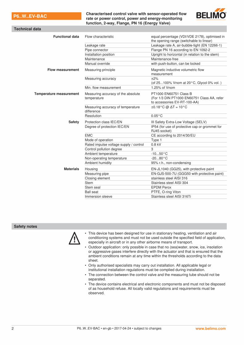
Mode of operation The final controlling device is comprised of four components: characterised control valve (CCV), measuring pipe with volumetric flow sensor, temperature sensors and the actuator itself. The adjusted maximum flow (max) is assigned to the maximum positioning signal (typically 10 V / 100%). Alternatively, the positioning signal can be assigned to the valve opening angle or to the power required on the heat exchanger (see power control). The final controlling device can be controlled communicative or analogue. The medium is detected by the sensor in the measuring pipe and is applied as the flow value. The measured value is balanced with the setpoint. The actuator corrects the deviation by changing the valve position. The angle of rotation α varies according to the differential pressure through the final controlling element (see flow rate curves).
Flow characteristic
Flow rate curves
α
∆p1 < ∆p2 < ∆p3
∆p3
∆p2
∆p1
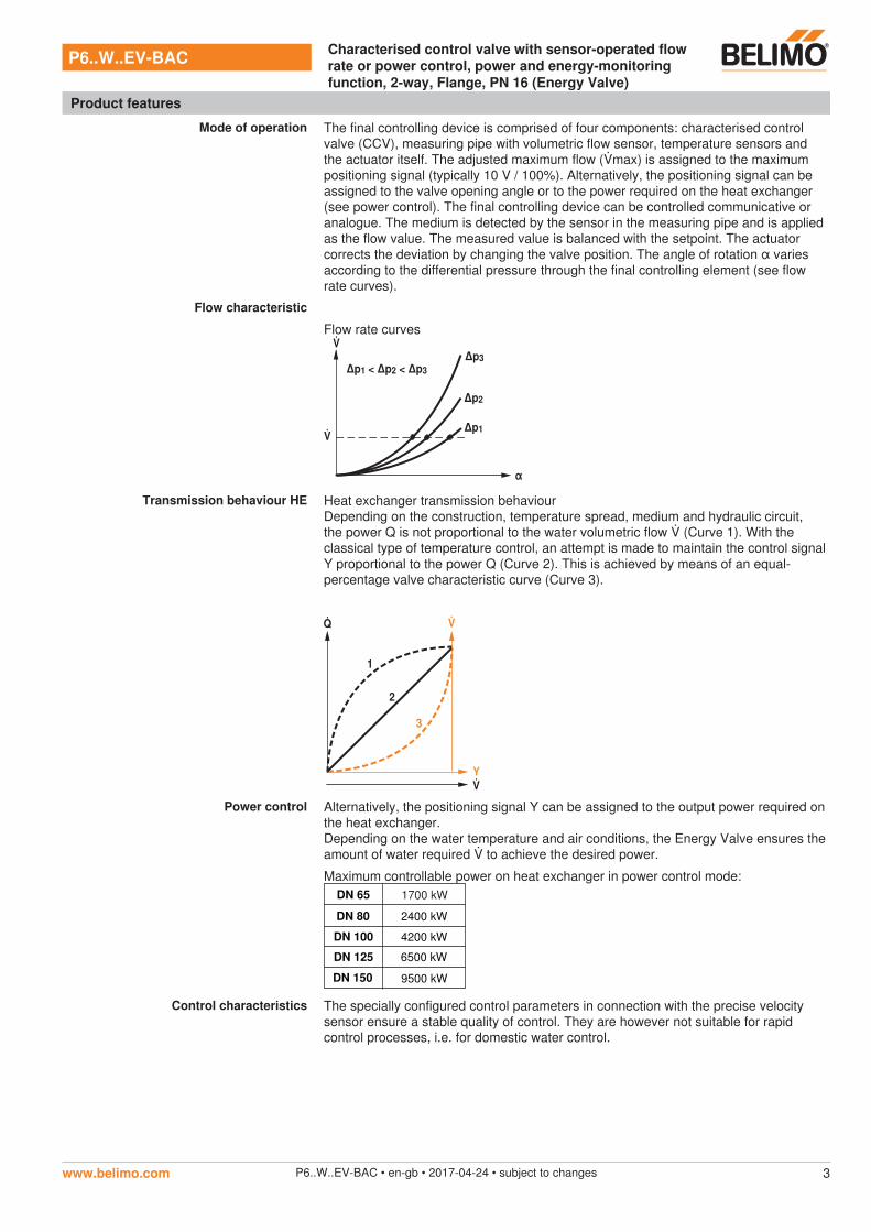
Transmission behaviour HE Heat exchanger transmission behaviourDepending on the construction, temperature spread, medium and hydraulic circuit, the power Q is not proportional to the water volumetric flow (Curve 1). With the classical type of temperature control, an attempt is made to maintain the control signal Y proportional to the power Q (Curve 2). This is achieved by means of an equal-percentage valve characteristic curve (Curve 3).
Y
3
1
2
Power control Alternatively, the positioning signal Y can be assigned to the output power required on the heat exchanger.Depending on the water temperature and air conditions, the Energy Valve ensures the amount of water required to achieve the desired power.
Maximum controllable power on heat exchanger in power control mode:DN 65 1700 kW
DN 80 2400 kW
DN 100 4200 kW
DN 125 6500 kW
DN 150 9500 kW
Control characteristics The specially configured control parameters in connection with the precise velocity sensor ensure a stable quality of control. They are however not suitable for rapid control processes, i.e. for domestic water control.
P6..W..EV-BAC Characterised control valve with sensor-operated flow rate or power control, power and energy-monitoring function, 2-way, Flange, PN 16 (Energy Valve)
Product features
www.belimo.com P6..W..EV-BAC • en-gb • 2017-04-24 • subject to changes 3
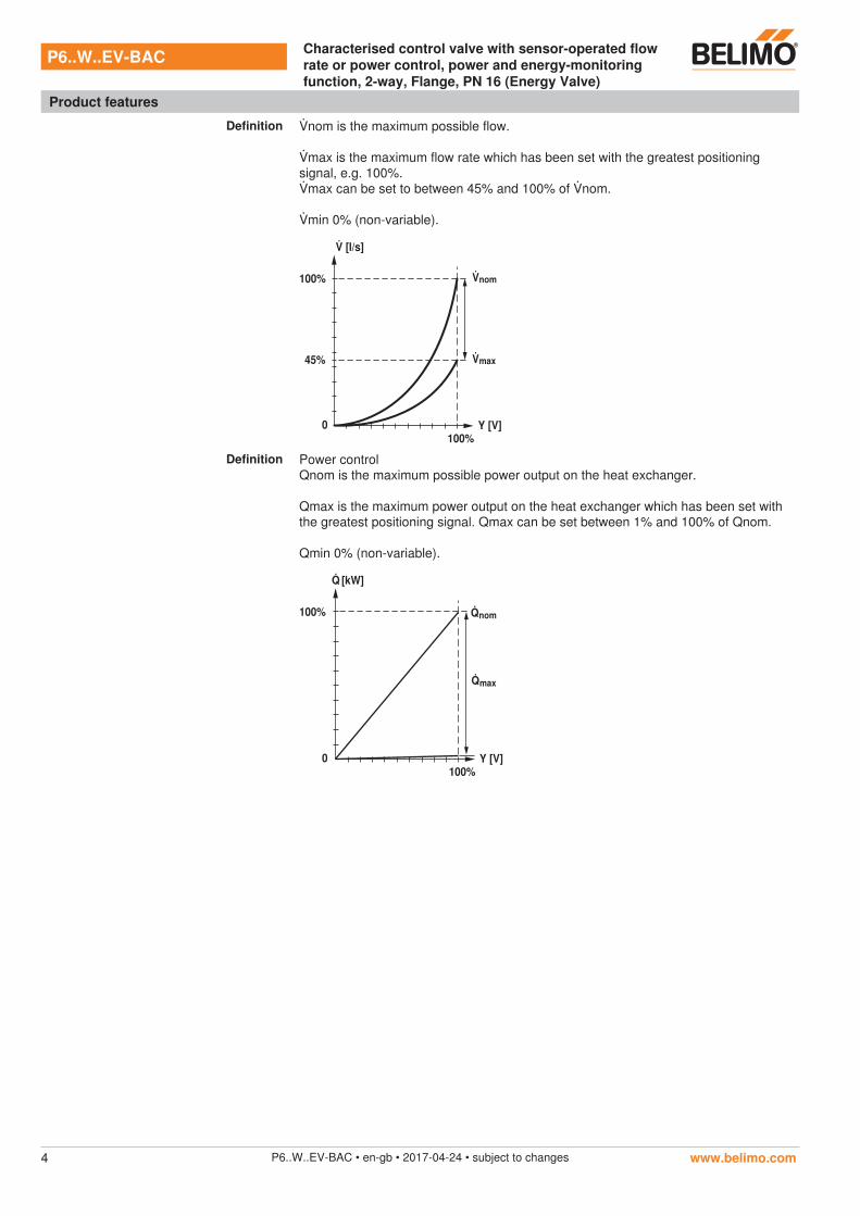
Definition nom is the maximum possible flow.
max is the maximum flow rate which has been set with the greatest positioning signal, e.g. 100%.max can be set to between 45% and 100% of nom.
min 0% (non-variable).
0100%
45%
100% nom
max
Y [V]
[l/s]
Definition Power controlQnom is the maximum possible power output on the heat exchanger.
Qmax is the maximum power output on the heat exchanger which has been set with the greatest positioning signal. Qmax can be set between 1% and 100% of Qnom.
Qmin 0% (non-variable).
100%Y [V]
[kW]
nom
0
100%
max
P6..W..EV-BAC Characterised control valve with sensor-operated flow rate or power control, power and energy-monitoring function, 2-way, Flange, PN 16 (Energy Valve)
Product features
www.belimo.comP6..W..EV-BAC • en-gb • 2017-04-24 • subject to changes4
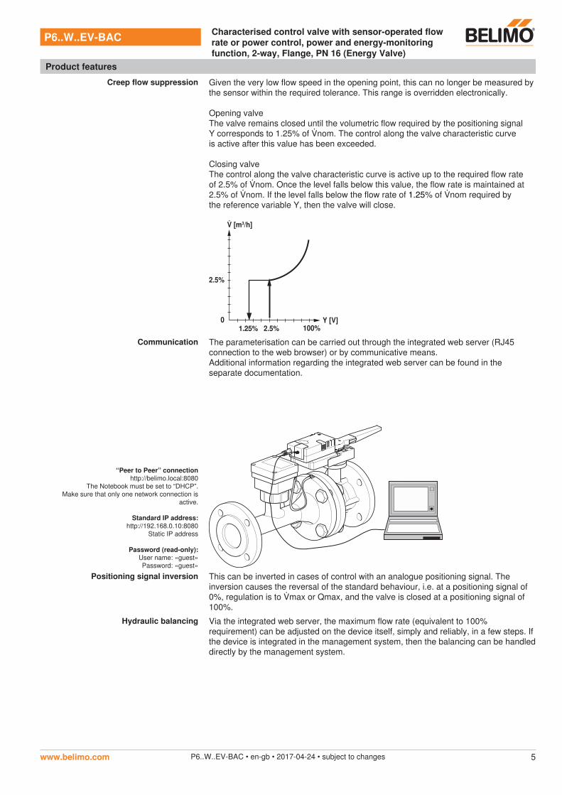
Creep flow suppression Given the very low flow speed in the opening point, this can no longer be measured by the sensor within the required tolerance. This range is overridden electronically.
Opening valveThe valve remains closed until the volumetric flow required by the positioning signal Y corresponds to 1.25% of nom. The control along the valve characteristic curve is active after this value has been exceeded.
Closing valveThe control along the valve characteristic curve is active up to the required flow rate of 2.5% of nom. Once the level falls below this value, the flow rate is maintained at 2.5% of nom. If the level falls below the flow rate of 1.25% of nom required by the reference variable Y, then the valve will close.
0
2.5%
1.25% 2.5% 100%Y [V]
[m3/h]
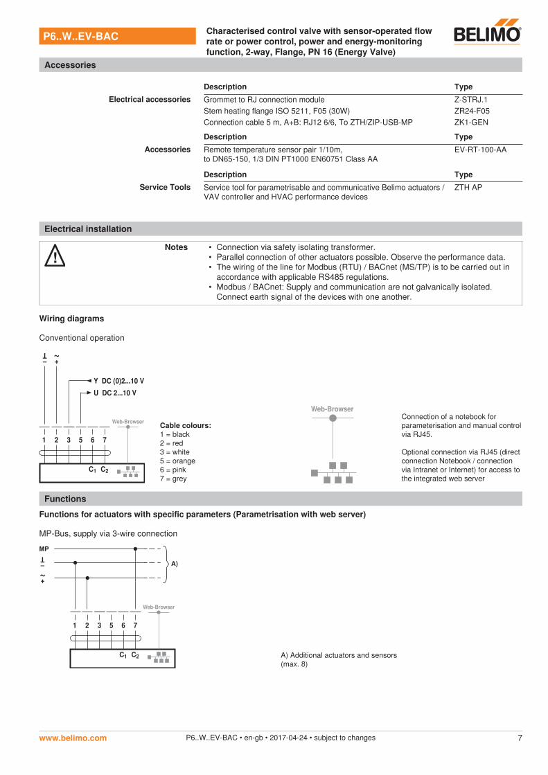
Communication The parameterisation can be carried out through the integrated web server (RJ45 connection to the web browser) or by communicative means.Additional information regarding the integrated web server can be found in the separate documentation.
“Peer to Peer” connection http://belimo.local:8080
The Notebook must be set to “DHCP”. Make sure that only one network connection is
active.
Standard IP address: http://192.168.0.10:8080
Static IP address
Password (read-only): User name: «guest» Password: «guest»
Positioning signal inversion This can be inverted in cases of control with an analogue positioning signal. The inversion causes the reversal of the standard behaviour, i.e. at a positioning signal of 0%, regulation is to max or Qmax, and the valve is closed at a positioning signal of 100%.
Hydraulic balancing Via the integrated web server, the maximum flow rate (equivalent to 100% requirement) can be adjusted on the device itself, simply and reliably, in a few steps. If the device is integrated in the management system, then the balancing can be handled directly by the management system.
P6..W..EV-BAC Characterised control valve with sensor-operated flow rate or power control, power and energy-monitoring function, 2-way, Flange, PN 16 (Energy Valve)
Product features
www.belimo.com P6..W..EV-BAC • en-gb • 2017-04-24 • subject to changes 5
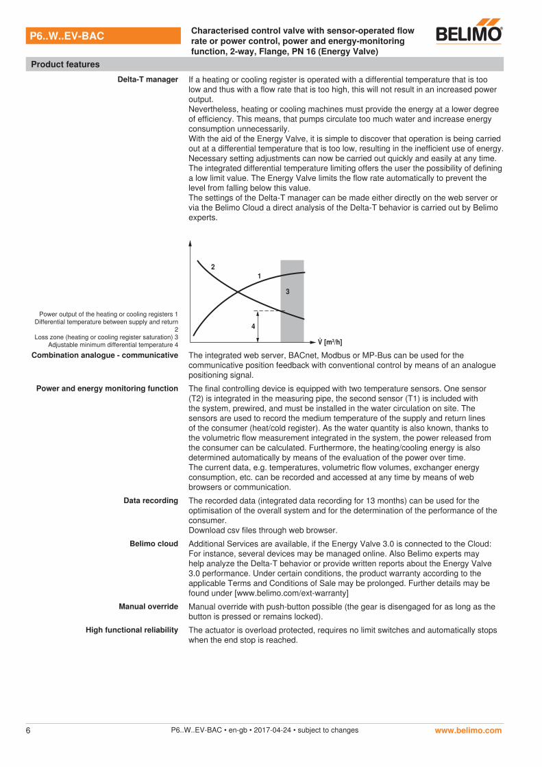
Delta-T manager If a heating or cooling register is operated with a differential temperature that is too low and thus with a flow rate that is too high, this will not result in an increased power output. Nevertheless, heating or cooling machines must provide the energy at a lower degree of efficiency. This means, that pumps circulate too much water and increase energy consumption unnecessarily.With the aid of the Energy Valve, it is simple to discover that operation is being carried out at a differential temperature that is too low, resulting in the inefficient use of energy. Necessary setting adjustments can now be carried out quickly and easily at any time. The integrated differential temperature limiting offers the user the possibility of defining a low limit value. The Energy Valve limits the flow rate automatically to prevent the level from falling below this value.The settings of the Delta-T manager can be made either directly on the web server or via the Belimo Cloud a direct analysis of the Delta-T behavior is carried out by Belimo experts.
Power output of the heating or cooling registers 1 Differential temperature between supply and return
2 Loss zone (heating or cooling register saturation) 3
Adjustable minimum differential temperature 4
4
2
[m3/h]
1
3
Combination analogue - communicative The integrated web server, BACnet, Modbus or MP-Bus can be used for the communicative position feedback with conventional control by means of an analogue positioning signal.
Power and energy monitoring function The final controlling device is equipped with two temperature sensors. One sensor (T2) is integrated in the measuring pipe, the second sensor (T1) is included with the system, prewired, and must be installed in the water circulation on site. The sensors are used to record the medium temperature of the supply and return lines of the consumer (heat/cold register). As the water quantity is also known, thanks to the volumetric flow measurement integrated in the system, the power released from the consumer can be calculated. Furthermore, the heating/cooling energy is also determined automatically by means of the evaluation of the power over time.The current data, e.g. temperatures, volumetric flow volumes, exchanger energy consumption, etc. can be recorded and accessed at any time by means of web browsers or communication.
Data recording The recorded data (integrated data recording for 13 months) can be used for the optimisation of the overall system and for the determination of the performance of the consumer.Download csv files through web browser.
Belimo cloud Additional Services are available, if the Energy Valve 3.0 is connected to the Cloud: For instance, several devices may be managed online. Also Belimo experts may help analyze the Delta-T behavior or provide written reports about the Energy Valve 3.0 performance. Under certain conditions, the product warranty according to the applicable Terms and Conditions of Sale may be prolonged. Further details may be found under [www.belimo.com/ext-warranty]
Manual override Manual override with push-button possible (the gear is disengaged for as long as the button is pressed or remains locked).
High functional reliability The actuator is overload protected, requires no limit switches and automatically stops when the end stop is reached.
P6..W..EV-BAC Characterised control valve with sensor-operated flow rate or power control, power and energy-monitoring function, 2-way, Flange, PN 16 (Energy Valve)
Product features
www.belimo.comP6..W..EV-BAC • en-gb • 2017-04-24 • subject to changes6
Description Type
Electrical accessories Grommet to RJ connection module Z-STRJ.1Stem heating flange ISO 5211, F05 (30W) ZR24-F05Connection cable 5 m, A+B: RJ12 6/6, To ZTH/ZIP-USB-MP ZK1-GEN
Description Type
Accessories Remote temperature sensor pair 1/10m,to DN65-150, 1/3 DIN PT1000 EN60751 Class AA
EV-RT-100-AA
Electrical installation
!Notes • Connection via safety isolating transformer.
• Parallel connection of other actuators possible. Observe the performance data.• The wiring of the line for Modbus (RTU) / BACnet (MS/TP) is to be carried out in
accordance with applicable RS485 regulations.• Modbus / BACnet: Supply and communication are not galvanically isolated.
Connect earth signal of the devices with one another.
Wiring diagrams
Conventional operation
1 2 3 5
+
~
–
T
6
C1
7
C2
Web-Browser
Y DC (0)2...10 V
U DC 2...10 V
Cable colours:1 = black 2 = red 3 = white 5 = orange 6 = pink 7 = grey
Web-BrowserConnection of a notebook for parameterisation and manual control via RJ45.
Optional connection via RJ45 (direct connection Notebook / connection via Intranet or Internet) for access to the integrated web server
Functions
Functions for actuators with specific parameters (Parametrisation with web server)
MP-Bus, supply via 3-wire connection
1 2 3 5 6
C1
7
C2
Web-Browser
+
~–
T
MP
A)
A) Additional actuators and sensors(max. 8)
P6..W..EV-BAC Characterised control valve with sensor-operated flow rate or power control, power and energy-monitoring function, 2-way, Flange, PN 16 (Energy Valve)
Accessories
www.belimo.com P6..W..EV-BAC • en-gb • 2017-04-24 • subject to changes 7
Description Type
Service Tools Service tool for parametrisable and communicative Belimo actuators / VAV controller and HVAC performance devices
ZTH AP
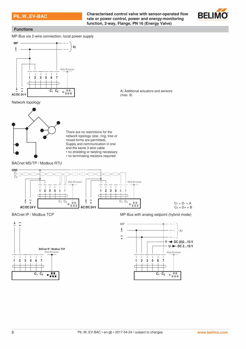
MP-Bus via 2-wire connection, local power supply
1 2 3 5 6
C1
7
C2
Web-Browser
+
~
–
T
AC/DC 24 V
MP
A)
–
T
A) Additional actuators and sensors(max. 8)
Network topology
There are no restrictions for the network topology (star, ring, tree or mixed forms are permitted).Supply and communication in one and the same 3-wire cable • no shielding or twisting necessary• no terminating resistors required
BACnet MS/TP / Modbus RTU
1 2 3 5 6 7
+
~
–
T
AC/DC 24 V
1 2 3 5 6 7
+
~
–
T
AC/DC 24 V
GND
Web-BrowserWeb-Browser
C1 C2 C1 C2
C2
C1
C₁ = D- = AC₂ = D+ = B
BACnet IP / Modbus TCP MP-Bus with analog setpoint (hybrid mode)
1 2 3 5 6
C1
7
C2
BACnet IP / Modbus TCP
+
~
–
T
Web-Browser
1 2 3 5 6
C1
7
C2
Web-Browser
+
~–
T
MP
A)
Y
U
DC (0)2…10 V
DC 2…10 V
P6..W..EV-BAC Characterised control valve with sensor-operated flow rate or power control, power and energy-monitoring function, 2-way, Flange, PN 16 (Energy Valve)
Functions
www.belimo.comP6..W..EV-BAC • en-gb • 2017-04-24 • subject to changes8
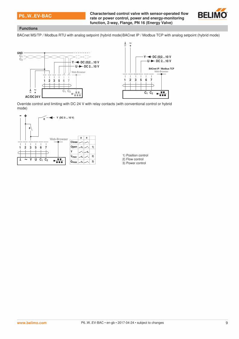
BACnet MS/TP / Modbus RTU with analog setpoint (hybrid mode)BACnet IP / Modbus TCP with analog setpoint (hybrid mode)
1 2 3 5 6 7
+
~
–
T
AC/DC 24 V
GND
Web-Browser
C1 C2
C2
C1
Y
U
DC (0)2…10 V
DC 2…10 V
1 2 3 5 6
C1
7
C2
BACnet IP / Modbus TCP
+
~
–
T
Web-Browser
Y
U
DC (0)2…10 V
DC 2…10 V
Override control and limiting with DC 24 V with relay contacts (with conventional control or hybrid mode)
- +
a
U
T ~
Y
e
a e
Close
Open
Y
Y (DC 0 ... 10 V)
1 2 3 5 6
C1
7
C2
Web-Browser
2)
1)
3)Q
1) Position control2) Flow control3) Power control
P6..W..EV-BAC Characterised control valve with sensor-operated flow rate or power control, power and energy-monitoring function, 2-way, Flange, PN 16 (Energy Valve)
Functions
www.belimo.com P6..W..EV-BAC • en-gb • 2017-04-24 • subject to changes 9
AdaptionStatus
2
3
4
5
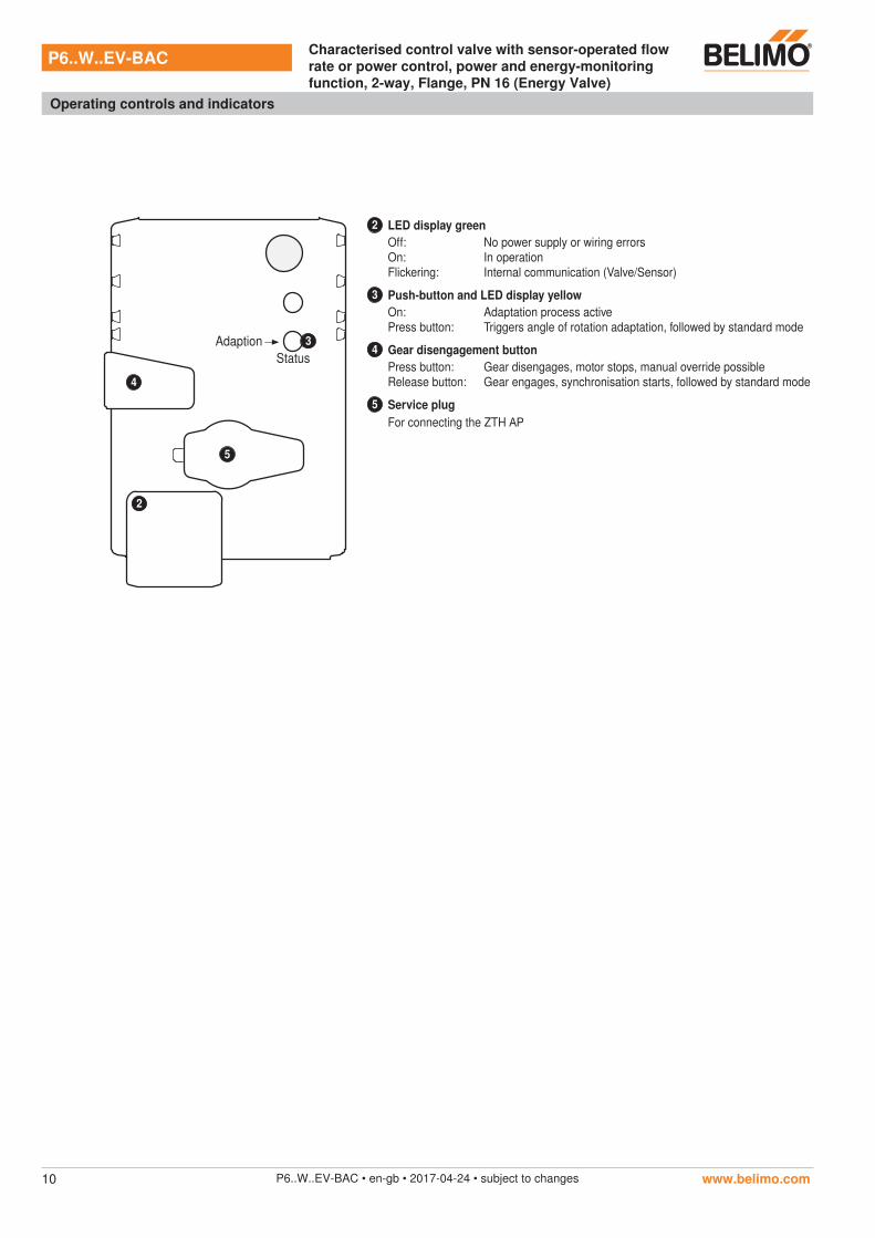
2 LED display greenOff:On:Flickering:
No power supply or wiring errorsIn operationInternal communication (Valve/Sensor)
3 Push-button and LED display yellowOn:Press button:
Adaptation process activeTriggers angle of rotation adaptation, followed by standard mode
4 Gear disengagement buttonPress button:Release button:
Gear disengages, motor stops, manual override possibleGear engages, synchronisation starts, followed by standard mode
5 Service plugFor connecting the ZTH AP
P6..W..EV-BAC Characterised control valve with sensor-operated flow rate or power control, power and energy-monitoring function, 2-way, Flange, PN 16 (Energy Valve)
Operating controls and indicators
www.belimo.comP6..W..EV-BAC • en-gb • 2017-04-24 • subject to changes10
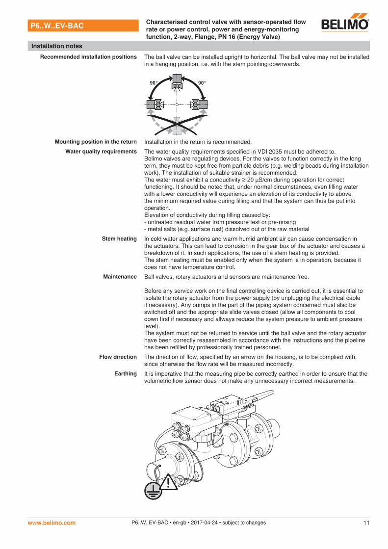
Recommended installation positions The ball valve can be installed upright to horizontal. The ball valve may not be installed in a hanging position, i.e. with the stem pointing downwards.
90° 90°
Mounting position in the return Installation in the return is recommended.
Water quality requirements The water quality requirements specified in VDI 2035 must be adhered to.Belimo valves are regulating devices. For the valves to function correctly in the long term, they must be kept free from particle debris (e.g. welding beads during installation work). The installation of suitable strainer is recommended.The water must exhibit a conductivity ≥ 20 µS/cm during operation for correct functioning. It should be noted that, under normal circumstances, even filling water with a lower conductivity will experience an elevation of its conductivity to above the minimum required value during filling and that the system can thus be put into operation.Elevation of conductivity during filling caused by:- untreated residual water from pressure test or pre-rinsing- metal salts (e.g. surface rust) dissolved out of the raw material
Stem heating In cold water applications and warm humid ambient air can cause condensation in the actuators. This can lead to corrosion in the gear box of the actuator and causes a breakdown of it. In such applications, the use of a stem heating is provided.The stem heating must be enabled only when the system is in operation, because it does not have temperature control.
Maintenance Ball valves, rotary actuators and sensors are maintenance-free.
Before any service work on the final controlling device is carried out, it is essential to isolate the rotary actuator from the power supply (by unplugging the electrical cable if necessary). Any pumps in the part of the piping system concerned must also be switched off and the appropriate slide valves closed (allow all components to cool down first if necessary and allways reduce the system pressure to ambient pressure level).The system must not be returned to service until the ball valve and the rotary actuator have been correctly reassembled in accordance with the instructions and the pipeline has been refilled by professionally trained personnel.
Flow direction The direction of flow, specified by an arrow on the housing, is to be complied with, since otherwise the flow rate will be measured incorrectly.
Earthing It is imperative that the measuring pipe be correctly earthed in order to ensure that the volumetric flow sensor does not make any unnecessary incorrect measurements.
P6..W..EV-BAC Characterised control valve with sensor-operated flow rate or power control, power and energy-monitoring function, 2-way, Flange, PN 16 (Energy Valve)
Installation notes
www.belimo.com P6..W..EV-BAC • en-gb • 2017-04-24 • subject to changes 11
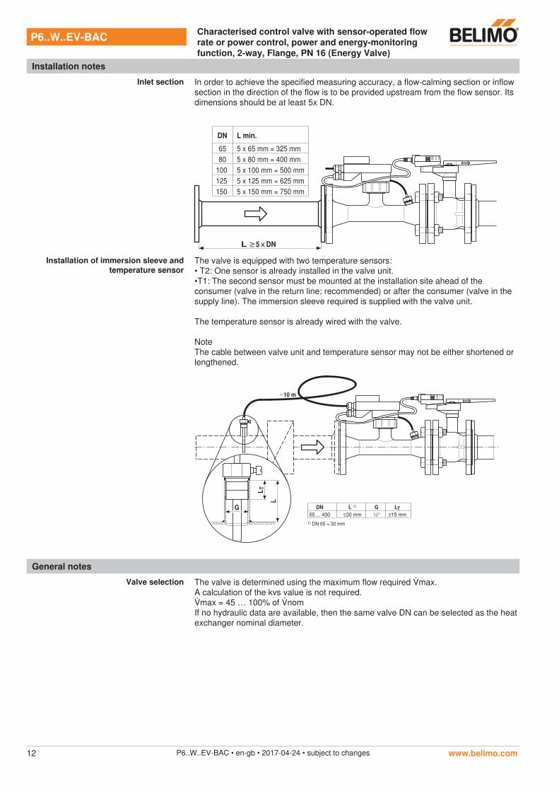
Inlet section In order to achieve the specified measuring accuracy, a flow-calming section or inflow section in the direction of the flow is to be provided upstream from the flow sensor. Its dimensions should be at least 5x DN.
DN L min.
65 5 x 65 mm = 325 mm
80 5 x 80 mm = 400 mm
100 5 x 100 mm = 500 mm
125 5 x 125 mm = 625 mm
150 5 x 150 mm = 750 mm
L ≥ 5 x DN
Installation of immersion sleeve and temperature sensor
The valve is equipped with two temperature sensors:• T2: One sensor is already installed in the valve unit.•T1: The second sensor must be mounted at the installation site ahead of theconsumer (valve in the return line; recommended) or after the consumer (valve in thesupply line). The immersion sleeve required is supplied with the valve unit.
The temperature sensor is already wired with the valve.
NoteThe cable between valve unit and temperature sensor may not be either shortened or lengthened.
~ 10 m
G
LT
L
DN L 1) G L
65 ... 400 ≤30 mm ½“ ≥15 mm
1) DN 65 = 30 mm
T
General notes
Valve selection The valve is determined using the maximum flow required max.A calculation of the kvs value is not required.max = 45 … 100% of nomIf no hydraulic data are available, then the same valve DN can be selected as the heat exchanger nominal diameter.
P6..W..EV-BAC Characterised control valve with sensor-operated flow rate or power control, power and energy-monitoring function, 2-way, Flange, PN 16 (Energy Valve)
Installation notes
www.belimo.comP6..W..EV-BAC • en-gb • 2017-04-24 • subject to changes12
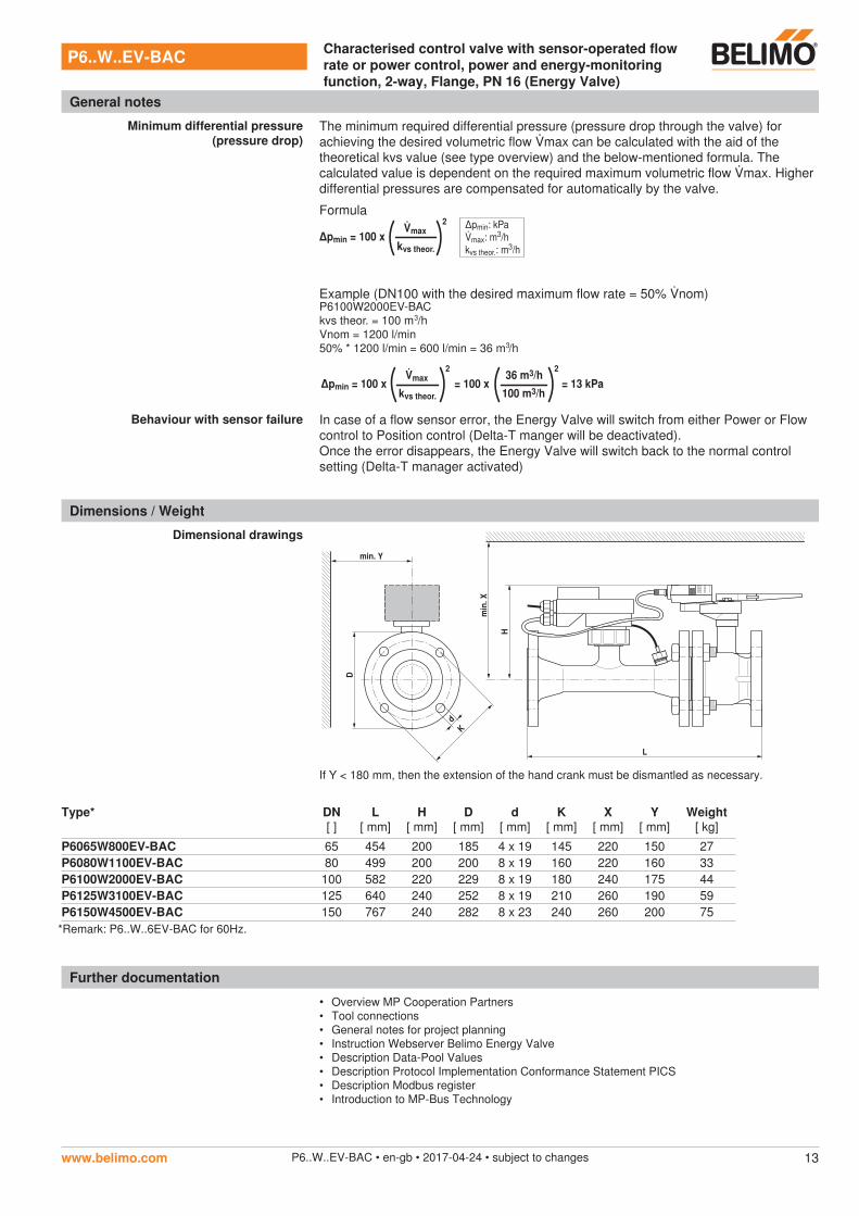
Minimum differential pressure (pressure drop)
The minimum required differential pressure (pressure drop through the valve) for achieving the desired volumetric flow max can be calculated with the aid of the theoretical kvs value (see type overview) and the below-mentioned formula. The calculated value is dependent on the required maximum volumetric flow max. Higher differential pressures are compensated for automatically by the valve.
Formula
∆pmin = 100 xmax
kvs theor.
2 ∆pmin: kPamax: m3/hkvs theor.: m3/h
Example (DN100 with the desired maximum flow rate = 50% nom)
∆pmin = 100 xmax
kvs theor.
2
= 100 x = 13 kPa36 m3/h
100 m3/h
2
P6100W2000EV-BAC
kvs theor. = 100 m /h
Vnom = 1200 l/min
50% * 1200 l/min = 600 l/min = 36 m /h
3
3
Behaviour with sensor failure In case of a flow sensor error, the Energy Valve will switch from either Power or Flow control to Position control (Delta-T manger will be deactivated).Once the error disappears, the Energy Valve will switch back to the normal control setting (Delta-T manager activated)
Dimensions / Weight
Dimensional drawings
L
H
min
. X
min. Y
D
Kd
If Y < 180 mm, then the extension of the hand crank must be dismantled as necessary.
Type* DN[ ]
L[ mm]
H[ mm]
D[ mm]
d[ mm]
K[ mm]
X[ mm]
Y[ mm]
Weight[ kg]
P6065W800EV-BAC 65 454 200 185 4 x 19 145 220 150 27P6080W1100EV-BAC 80 499 200 200 8 x 19 160 220 160 33P6100W2000EV-BAC 100 582 220 229 8 x 19 180 240 175 44P6125W3100EV-BAC 125 640 240 252 8 x 19 210 260 190 59P6150W4500EV-BAC 150 767 240 282 8 x 23 240 260 200 75
Further documentation
• Overview MP Cooperation Partners• Tool connections• General notes for project planning• Instruction Webserver Belimo Energy Valve• Description Data-Pool Values• Description Protocol Implementation Conformance Statement PICS• Description Modbus register• Introduction to MP-Bus Technology
P6..W..EV-BAC Characterised control valve with sensor-operated flow rate or power control, power and energy-monitoring function, 2-way, Flange, PN 16 (Energy Valve)
General notes
www.belimo.com P6..W..EV-BAC • en-gb • 2017-04-24 • subject to changes 13
*Remark: P6..W..6EV-BAC for 60Hz.


![Filles et garçons 2012...[ 12 ] fillesetgarçonssurlechemindel’égalité,del'écoleàl'enseignementsupérieur[2012] Les résultats Bac général Bac L Bac ES Bac S Bac techno Bac](https://img.dokumen.tips/doc/110x75/60dbc69bdcdd4d1dfb2b35f8/filles-et-garons-2012-12-fillesetgaronssurlechemindelagalitdelcolelenseignementsuprieur2012.jpg)


![MODBUS IINDUSTRIE sWETTERSTATIONNDUSTRIE …€¦ · MODBUS rain[e]one Modbus INDUSTRY Modbus Pyranometer THP[pro] Modbus rain one Modbus IN Wiegender Nieder-schlagssensor Windrichtung](https://img.dokumen.tips/doc/110x75/5eb88fa576fba607cd617fd5/modbus-iindustrie-swetterstationndustrie-modbus-raineone-modbus-industry-modbus.jpg)


![DPU2000/1500R/2000R MODBUS / MODBUS PLUS … · DPU2000/1500R/2000R Modbus/Modbus Plus Automation Guide i DPU2000/1500R/2000R MODBUS / MODBUS PLUS ... [Catalog 587XXX00-XXX0 or 587XXXX6-XXX4]](https://img.dokumen.tips/doc/110x75/5acb9eac7f8b9a73128bdc42/dpu20001500r2000r-modbus-modbus-plus-modbusmodbus-plus-automation-guide.jpg)