Embed Size (px)
Citation preview
Harefield Cardiac Course
S. EdyveanImPACT (Imaging Performance Assessment of CT Scanners)
St. Georges Hospital, Londonwww.impactscan.org
Technical Aspects of Cardiac CT

Harefield Cardiac Course
Technical Aspects of Cardiac CT
• Introduction• Multi-slice CT (MSCT)• Scanning the heart with MSCT• Improving
– Temporal resolution– Volume coverage– Spatial resolution
Harefield Cardiac Course
Cardiac CT
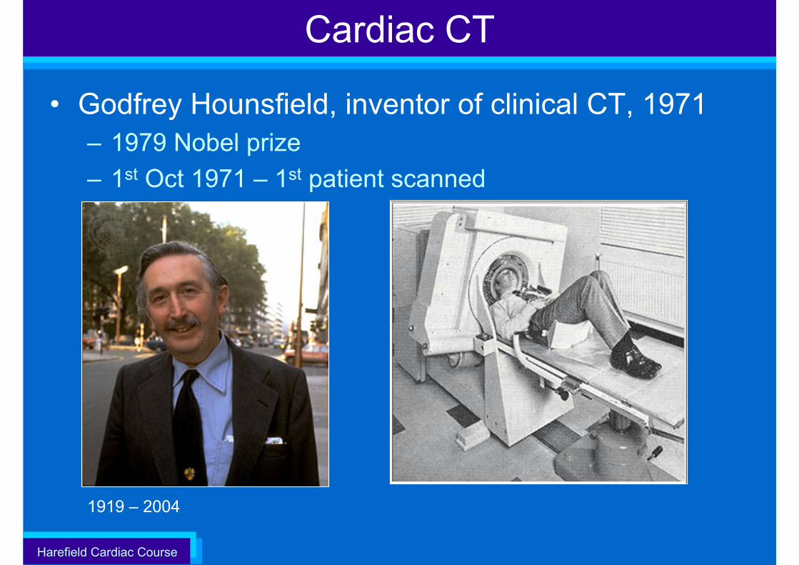
• Godfrey Hounsfield, inventor of clinical CT, 1971– 1979 Nobel prize– 1st Oct 1971 – 1st patient scanned
1919 – 2004
Harefield Cardiac Course
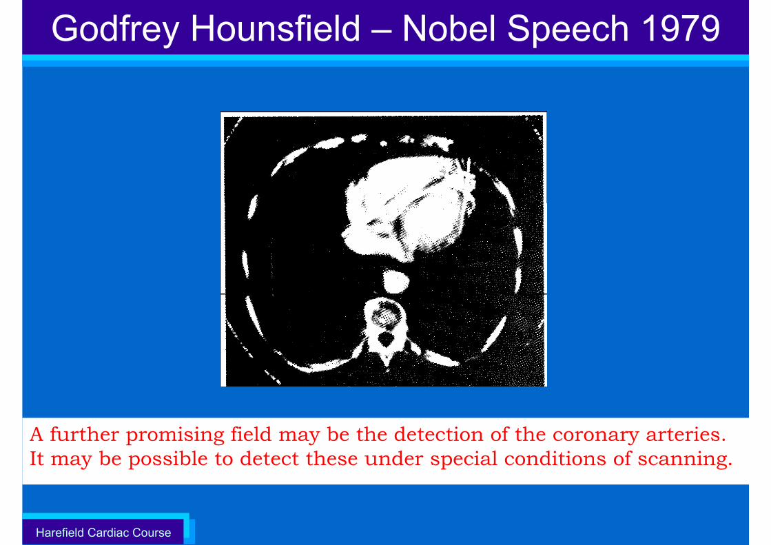
Godfrey Hounsfield – Nobel Speech 1979
A further promising field may be the detection of the coronary arteries. It may be possible to detect these under special conditions of scanning.
Harefield Cardiac Course
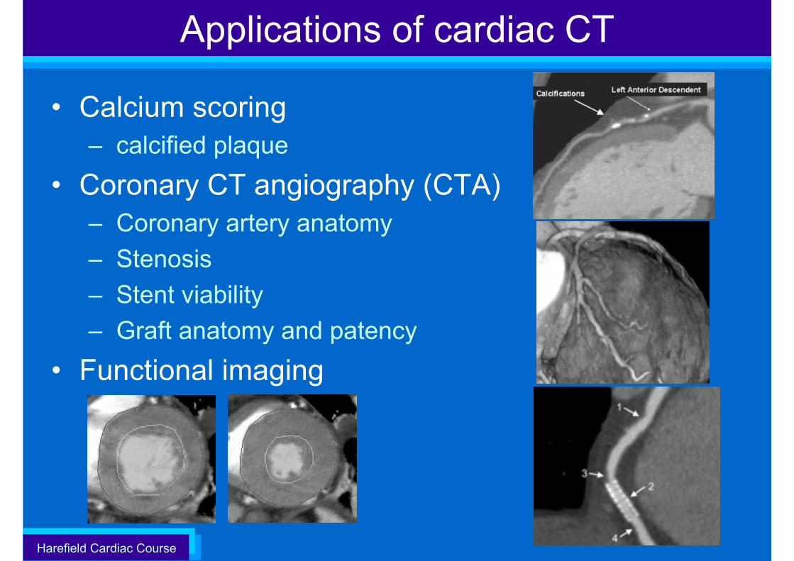
Applications of cardiac CT
• Calcium scoring – calcified plaque
• Coronary CT angiography (CTA)– Coronary artery anatomy– Stenosis– Stent viability– Graft anatomy and patency
• Functional imaging
Harefield Cardiac Course 6
Cardiac CT
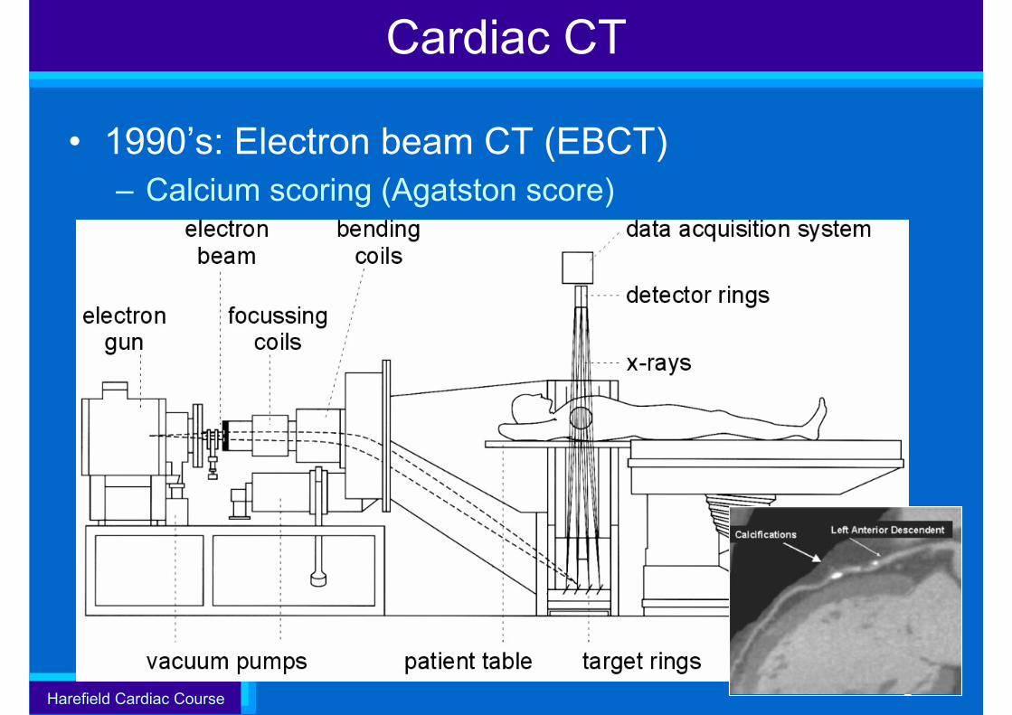
• 1990’s: Electron beam CT (EBCT)– Calcium scoring (Agatston score)
Harefield Cardiac Course
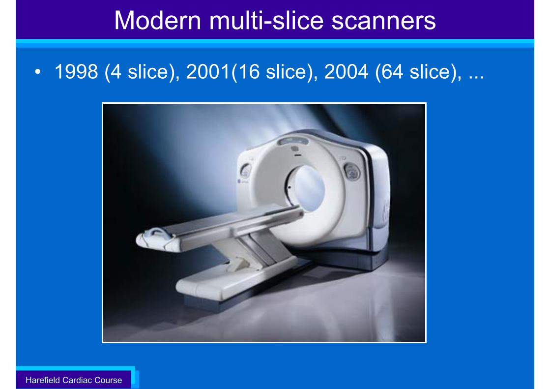
Modern multi-slice scanners
• 1998 (4 slice), 2001(16 slice), 2004 (64 slice), ...
Harefield Cardiac Course
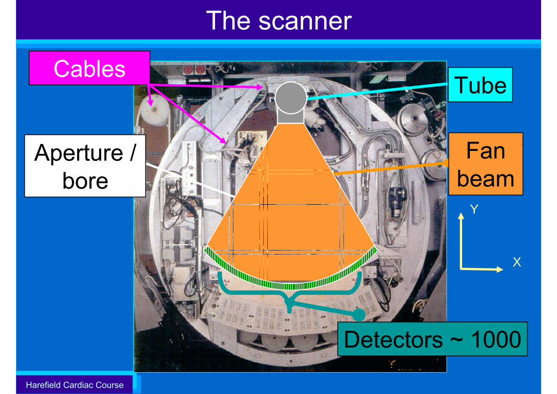
Tube
Detectors ~ 1000
Aperture / bore
The scanner
Cables
Fan beam
X
Y
Harefield Cardiac Course
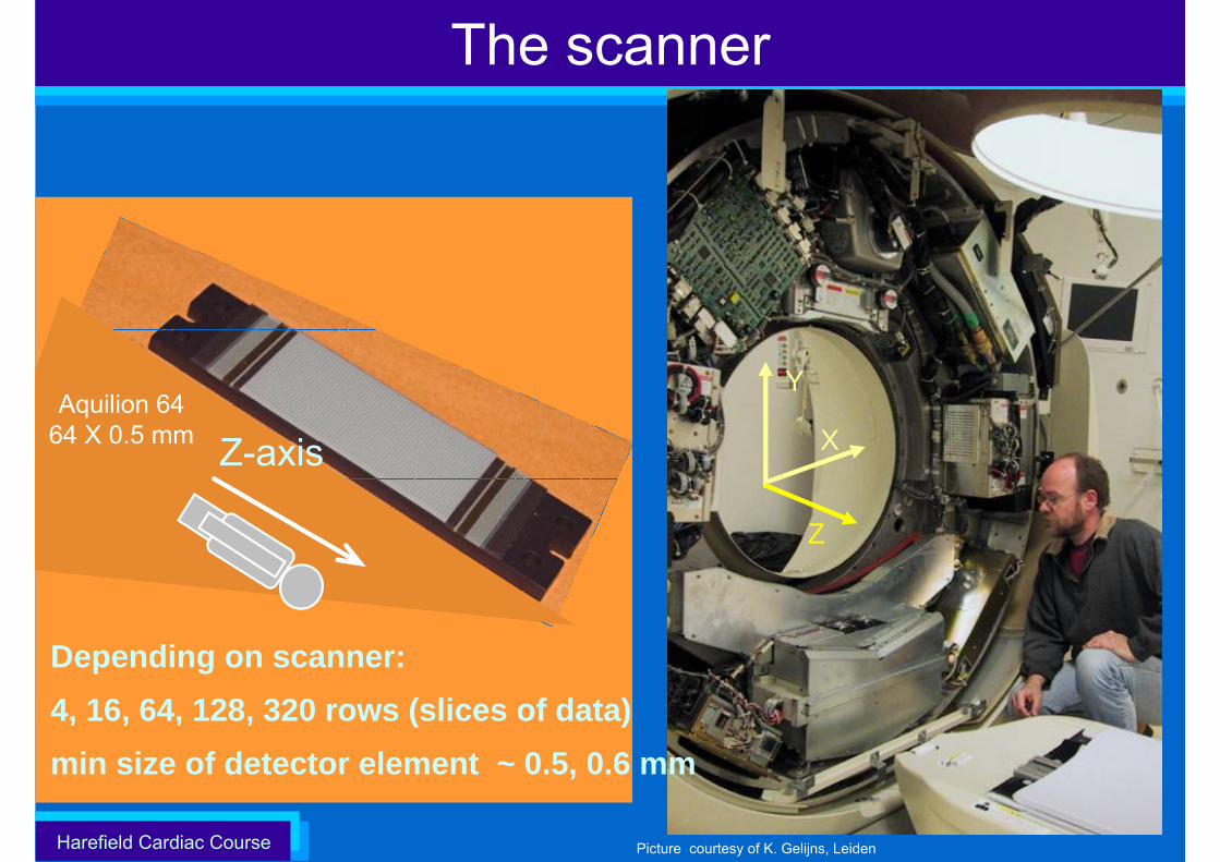
The scanner
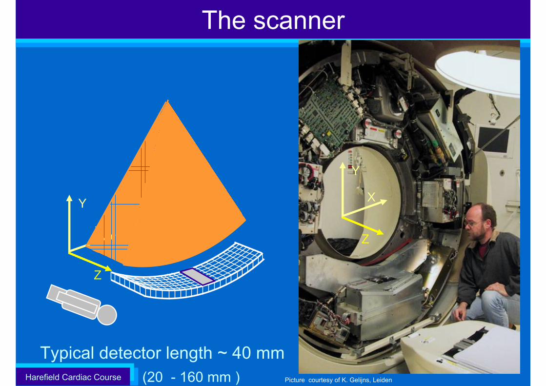
Picture courtesy of K. Gelijns, Leiden
X
Y
Z
X
Y
Z
(20 - 160 mm )Typical detector length ~ 40 mm
Harefield Cardiac Course
The scanner
64 x 0.5 = 32 mm
z-axis
Picture courtesy of K. Gelijns, Leiden
Z-axis X
Y
Z
Depending on scanner:4, 16, 64, 128, 320 rows (slices of data)min size of detector element ~ 0.5, 0.6 mm
Aquilion 6464 X 0.5 mm
Harefield Cardiac Course
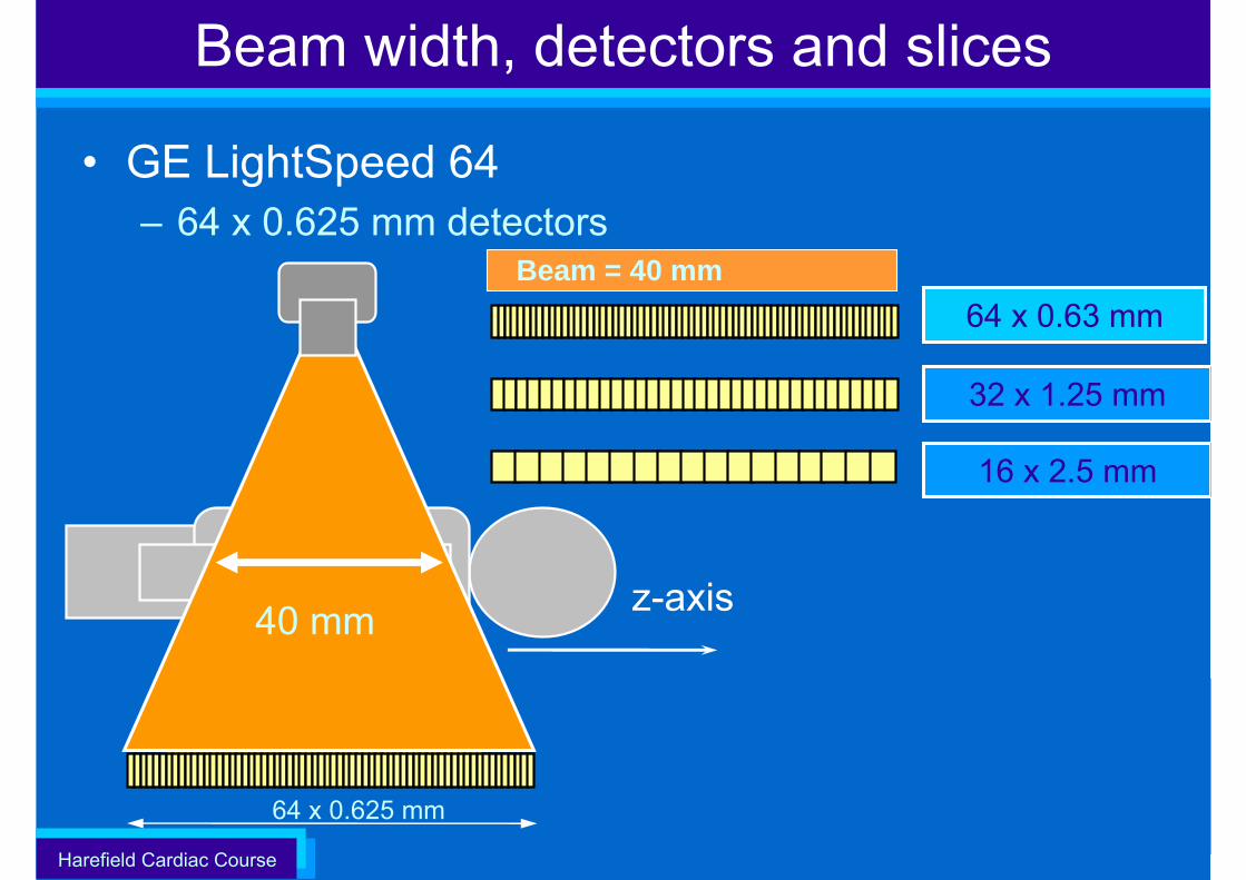
Beam width, detectors and slices
• GE LightSpeed 64– 64 x 0.625 mm detectors
32 x 1.25 mm
64 x 0.63 mm
z-axis
64 x 0.625 mm
16 x 2.5 mm
40 mm
8 x 2.5 mm
Beam = 40 mm
Beam = 20 mm
Harefield Cardiac Course
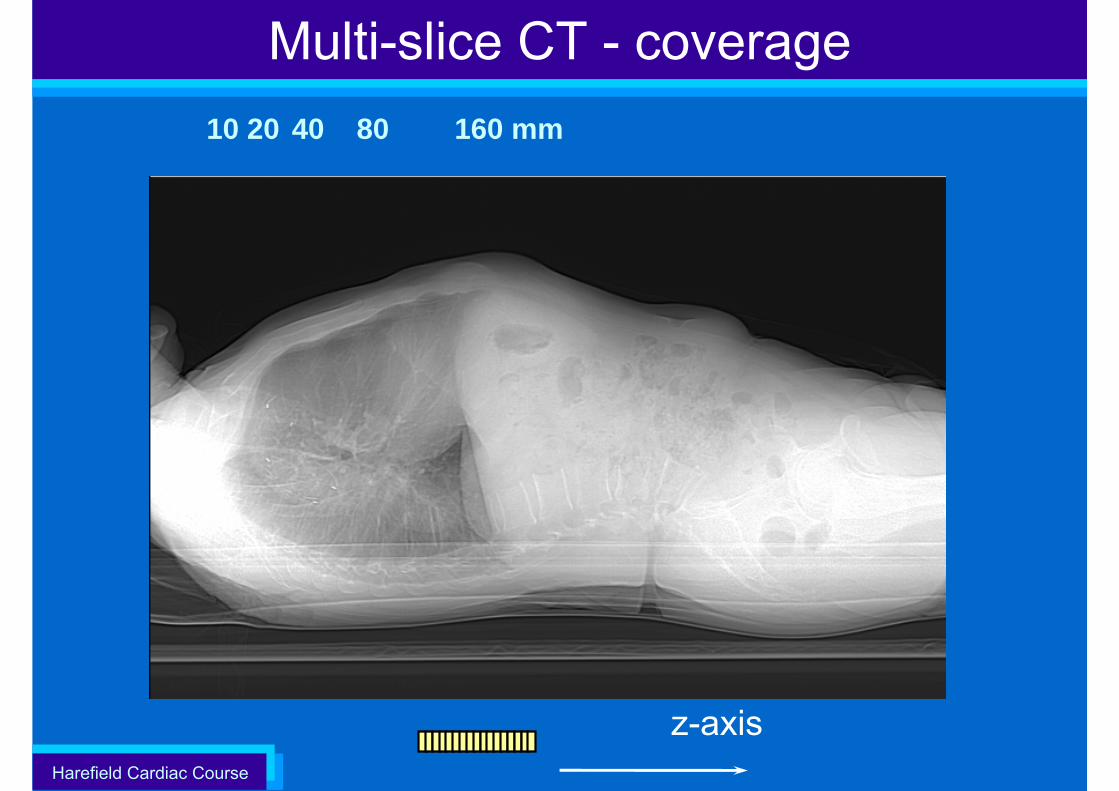
Multi-slice CT - coverage10 20 40 80 160 mm
z-axis
Harefield Cardiac Course
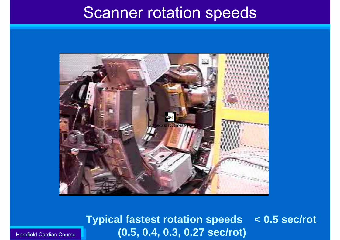
Scanner rotation speeds
Typical fastest rotation speeds < 0.5 sec/rot (0.5, 0.4, 0.3, 0.27 sec/rot)
0.3 Second rot timea.MPG
Harefield Cardiac Course
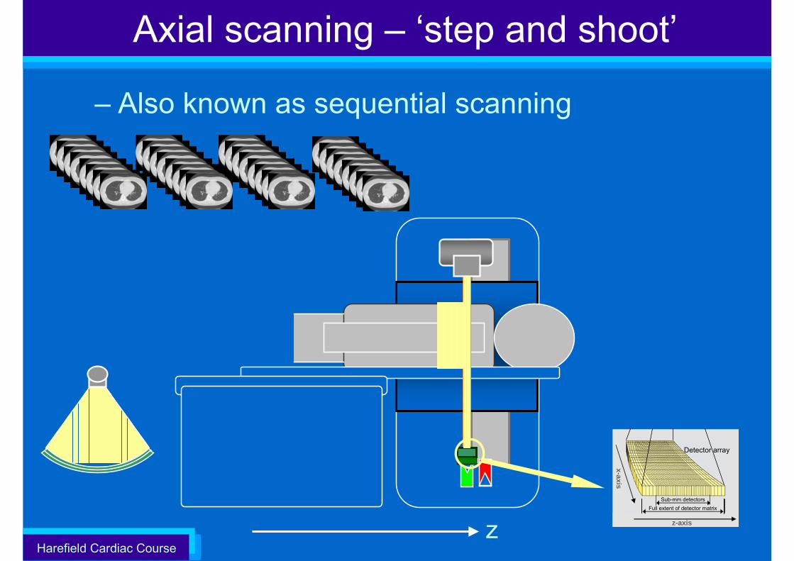
Axial scanning – ‘step and shoot’
– Also known as sequential scanning
z z-axis
x-axis
Detector array
z-axis
x-axis
z-axis
x-axis
Detector array
Sub-mm detectorsFull extent of detector matrix
Harefield Cardiac Course
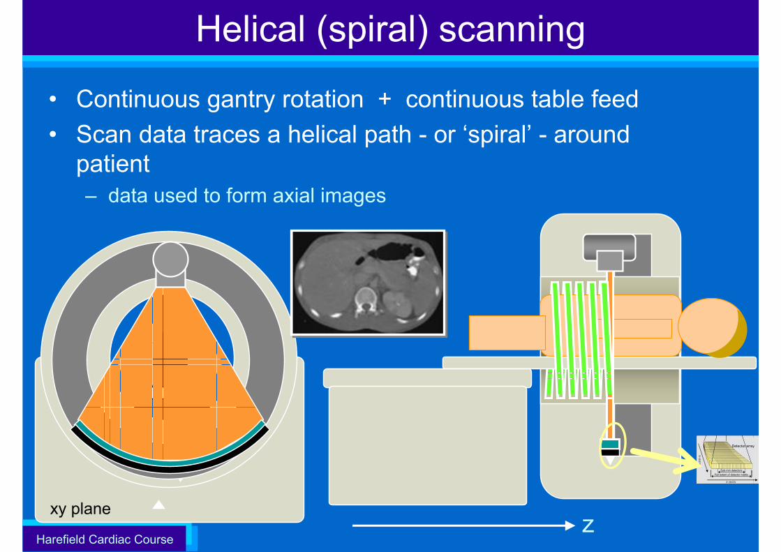
Helical (spiral) scanning
• Continuous gantry rotation + continuous table feed• Scan data traces a helical path - or ‘spiral’ - around
patient– data used to form axial images
xy plane
z-axis
x-axis
Detector array
z-axis
x-axis
z-axis
x-axis
Detector array
Sub-mm detectorsFull extent of detector matrix
z
Harefield Cardiac Course
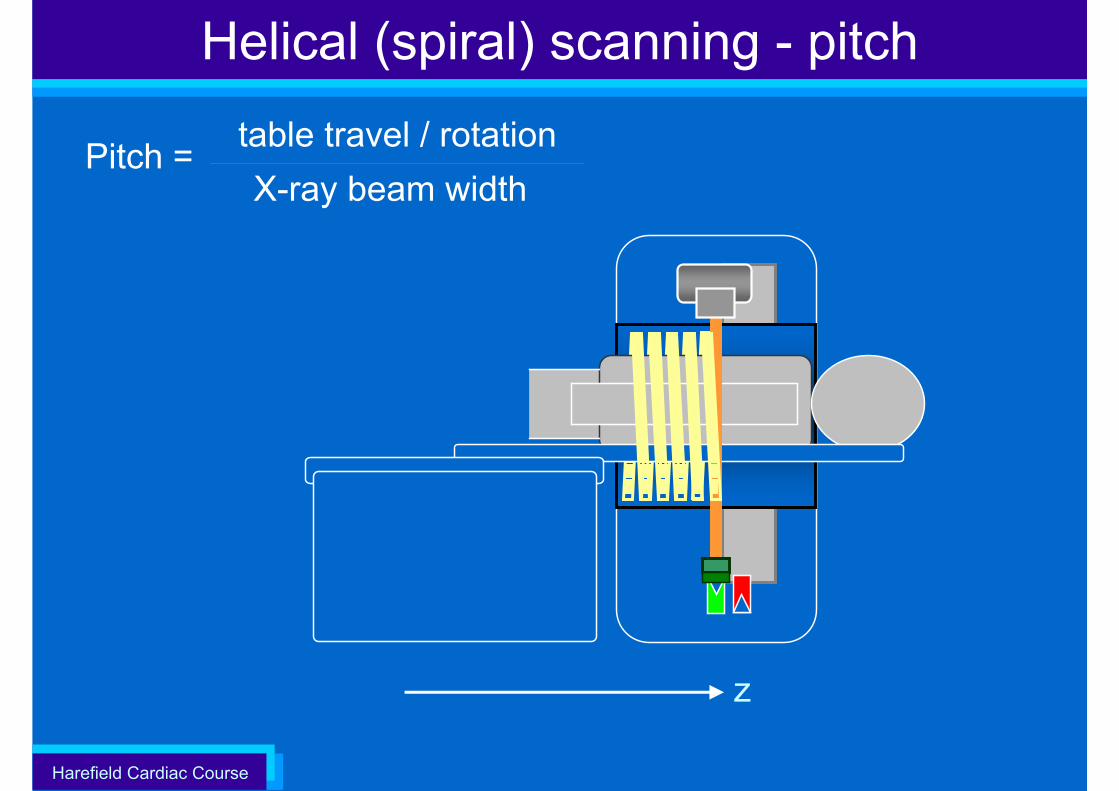
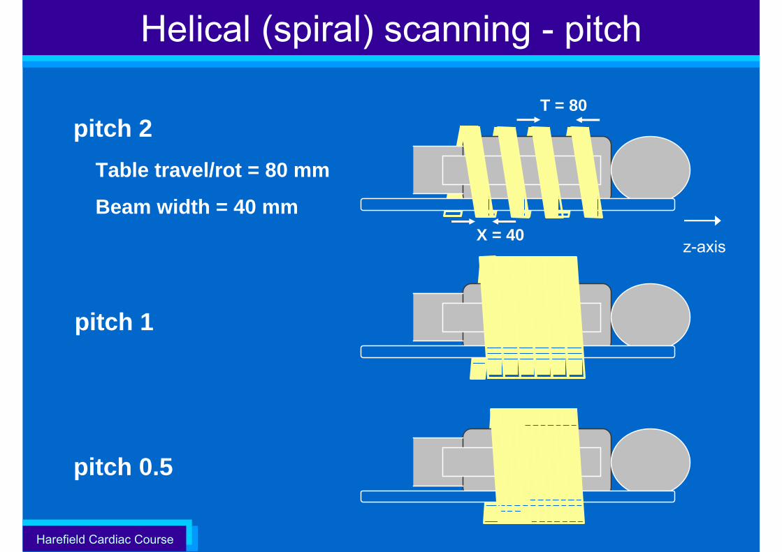
Helical (spiral) scanning - pitch
X-ray beam width Pitch = table travel / rotation
z
Harefield Cardiac Course
z-axisX = 40
T = 80pitch 2
Table travel/rot = 80 mm
Beam width = 40 mm
pitch 0.5
pitch 1
Helical (spiral) scanning - pitch
Harefield Cardiac Course
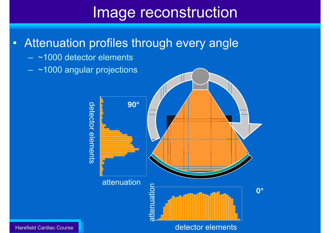
Image reconstruction
• Attenuation profiles through every angle– ~1000 detector elements – ~1000 angular projections
atte
nuat
ion
detector elements
0°attenuation
detector elements
90°
Harefield Cardiac Course
Harefield Cardiac Course
Harefield Cardiac Course
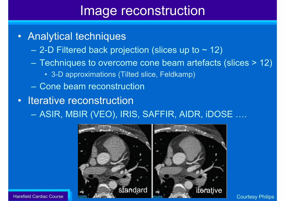
Image reconstruction
• Analytical techniques– 2-D Filtered back projection (slices up to ~ 12)– Techniques to overcome cone beam artefacts (slices > 12)
• 3-D approximations (Tilted slice, Feldkamp)
– Cone beam reconstruction• Iterative reconstruction
– ASIR, MBIR (VEO), IRIS, SAFFIR, AIDR, iDOSE ….
standard iterativeCourtesy Philips
Harefield Cardiac Course
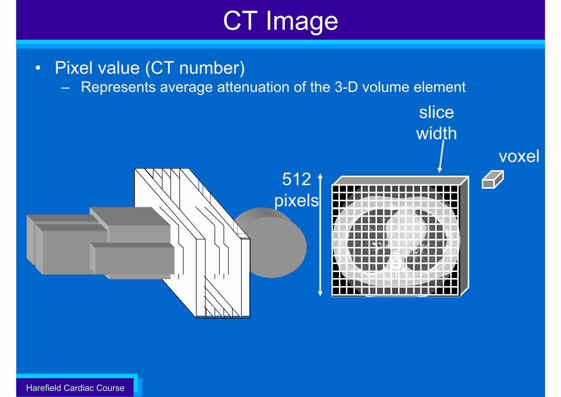
• Pixel value (CT number)– Represents average attenuation of the 3-D volume element
• Pixel size = fov / matrix – eg 350 / 512 = 0.68 mm, If 1024 matrix = 0.34 mm
CT Image
slicewidth
voxel512
pixels
Harefield Cardiac Course
Image presentation
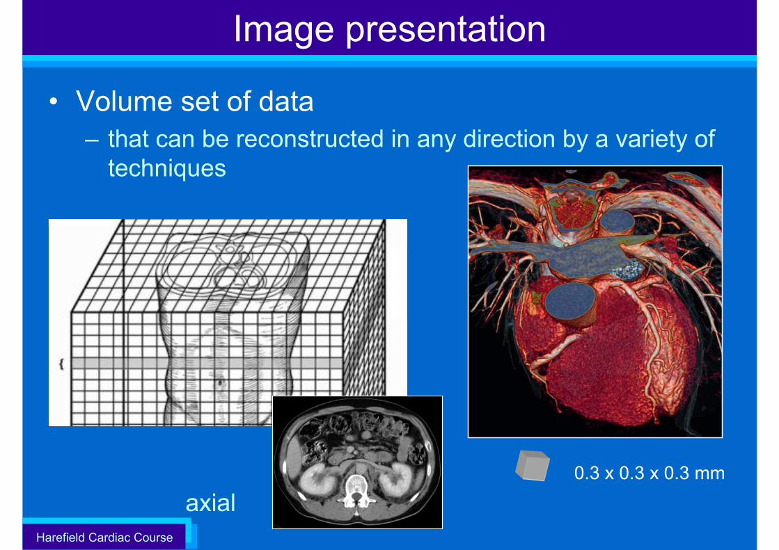
• Volume set of data – that can be reconstructed in any direction by a variety of
techniques
0.3 x 0.3 x 0.3 mm
axial
Harefield Cardiac Course
Technical Aspects of Cardiac CT
• Introduction• Multi-slice CT (MSCT)• Scanning the heart with MSCT• Improving
– Temporal resolution– Volume coverage– Spatial resolution
Harefield Cardiac Course
The heart
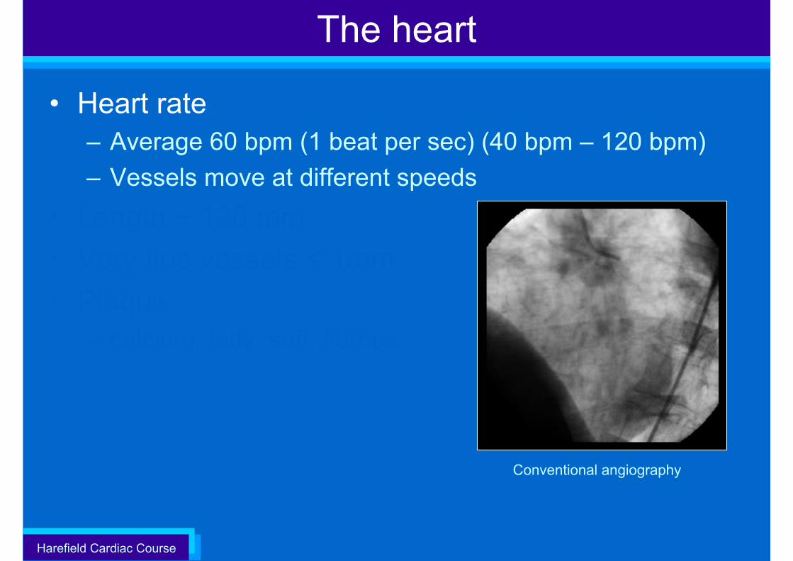
• Heart rate– Average 60 bpm (1 beat per sec) (40 bpm – 120 bpm) – Vessels move at different speeds
• Length ~ 120 mm• Very fine vessels < 1mm• Plaque
– calcium, fatty, soft, fibrous
Conventional angiography
Harefield Cardiac Course
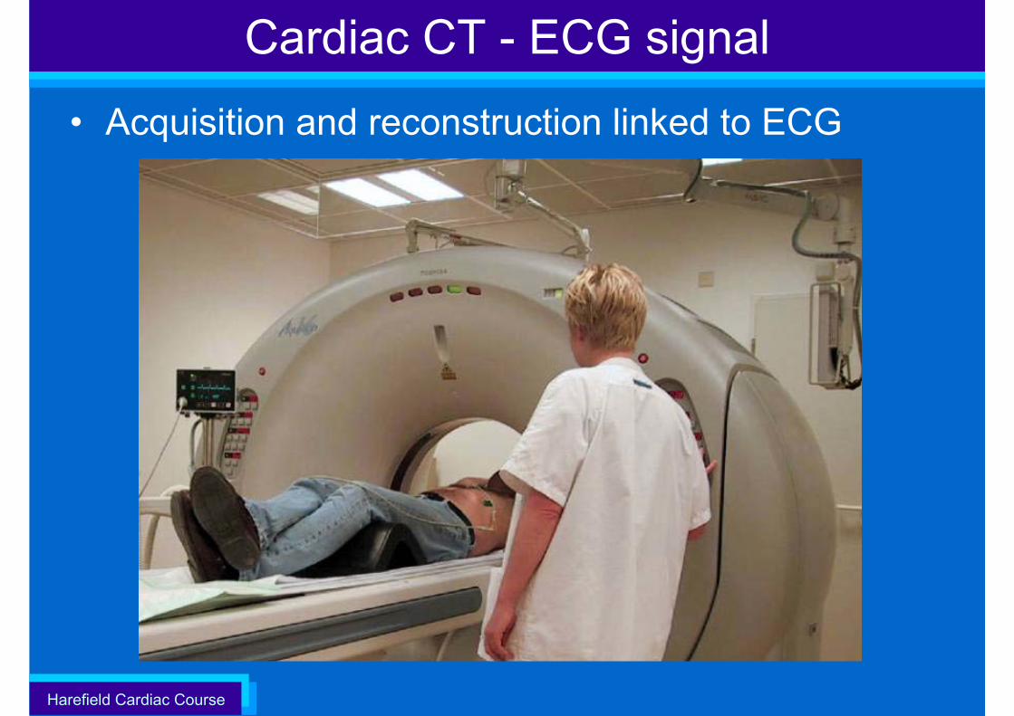
Cardiac CT - ECG signal
• Acquisition and reconstruction linked to ECG
Harefield Cardiac Course
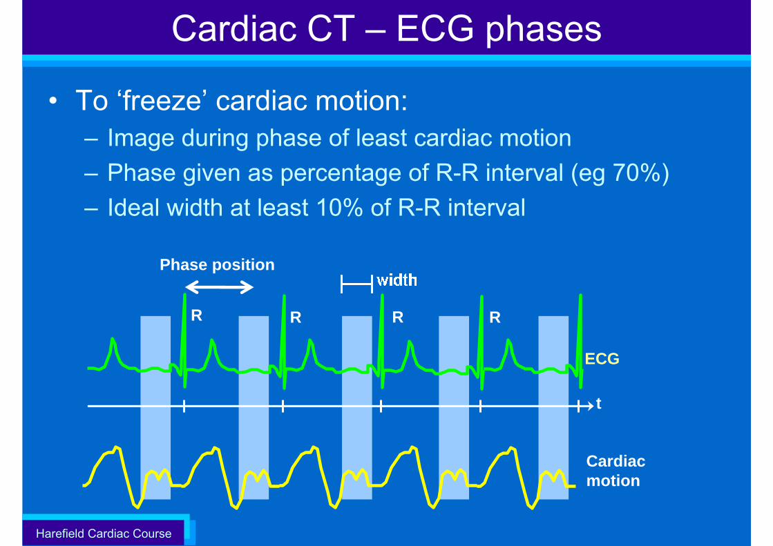
• To ‘freeze’ cardiac motion:– Image during phase of least cardiac motion– Phase given as percentage of R-R interval (eg 70%)– Ideal width at least 10% of R-R interval
Phase position
Cardiac CT – ECG phases
t
R
Cardiac motion
ECG
R R R
Harefield Cardiac Course
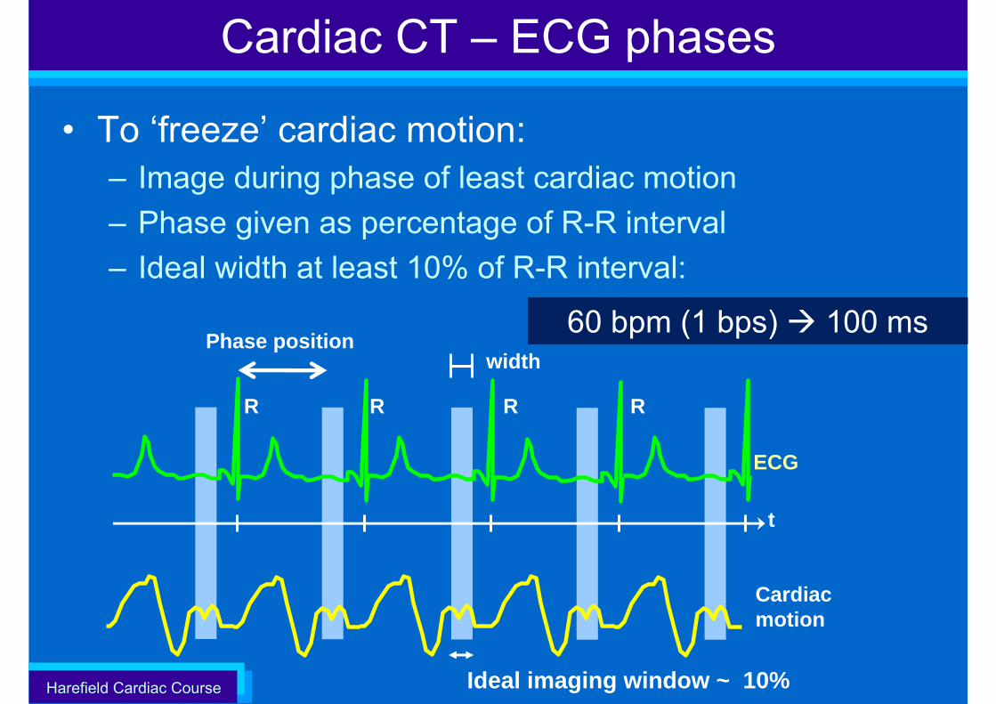
• To ‘freeze’ cardiac motion:– Image during phase of least cardiac motion– Phase given as percentage of R-R interval– Ideal width at least 10% of R-R interval:
Cardiac CT – ECG phases
t
R
Cardiac motion
ECG
R R R
width
Ideal imaging window ~ 10%
60 bpm (1 bps) 100 msPhase position
Harefield Cardiac Course
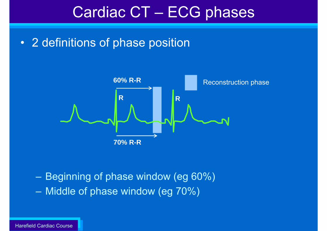
• 2 definitions of phase position
– Beginning of phase window (eg 60%)– Middle of phase window (eg 70%)
Cardiac CT – ECG phases
Reconstruction phase
70% R-R
60% R-R
R R
Harefield Cardiac Course
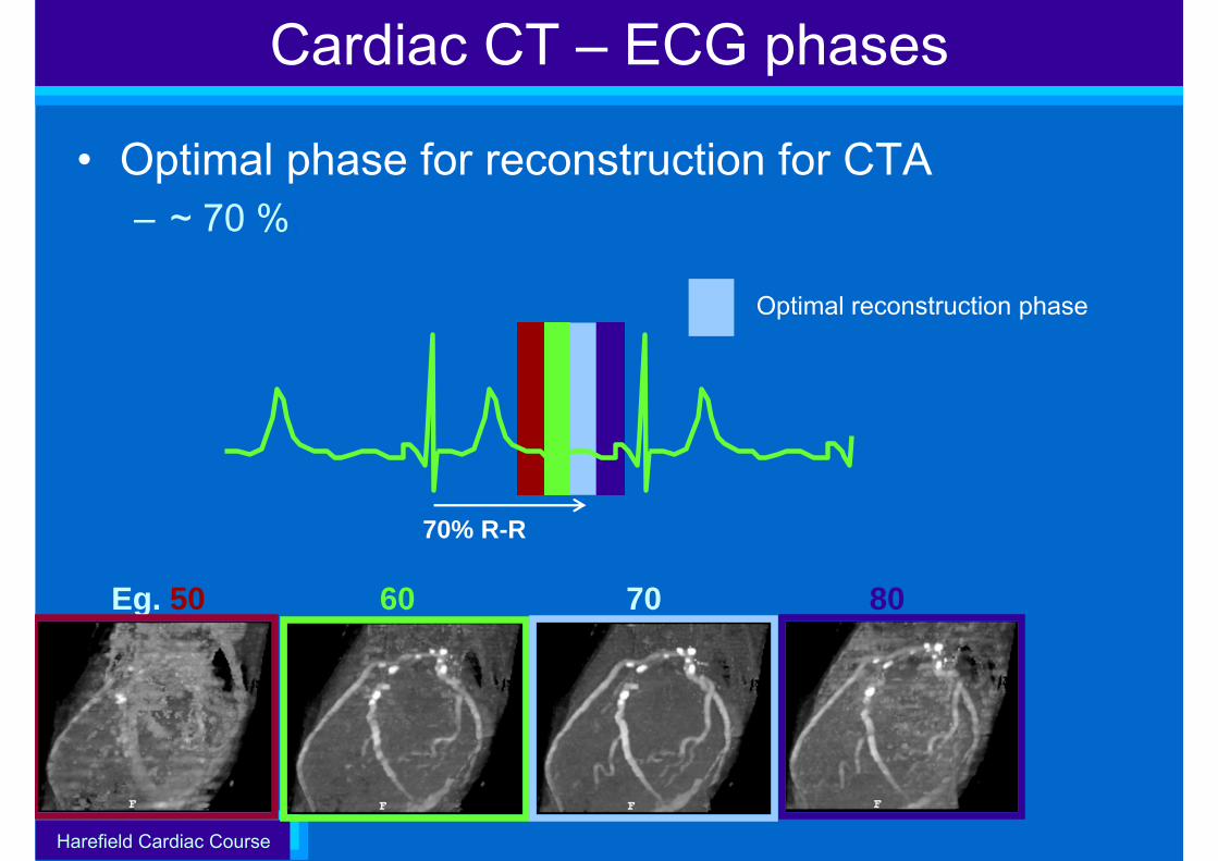
• Optimal phase for reconstruction for CTA– ~ 70 %(
Cardiac CT – ECG phases
Optimal reconstruction phase
8060Eg. 50 70
70% R-R
Harefield Cardiac Course
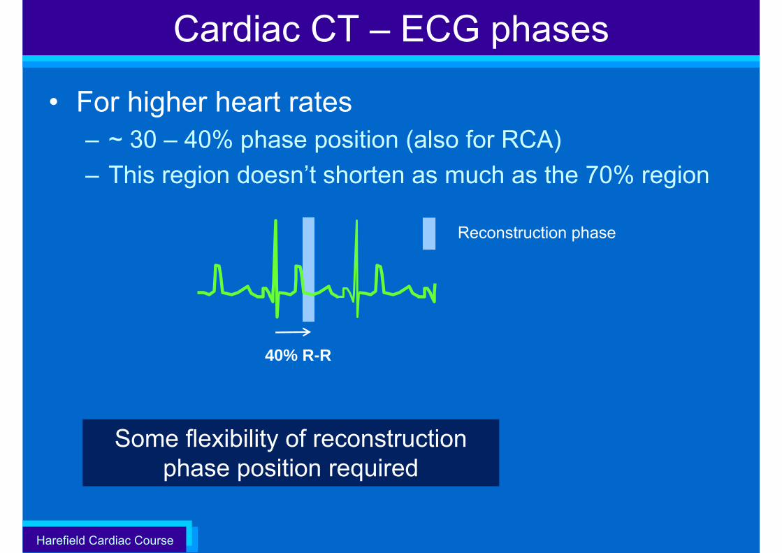
• For higher heart rates– ~ 30 – 40% phase position (also for RCA)– This region doesn’t shorten as much as the 70% region
Cardiac CT – ECG phases
Reconstruction phase
40% R-R
Some flexibility of reconstruction phase position required
Harefield Cardiac Course
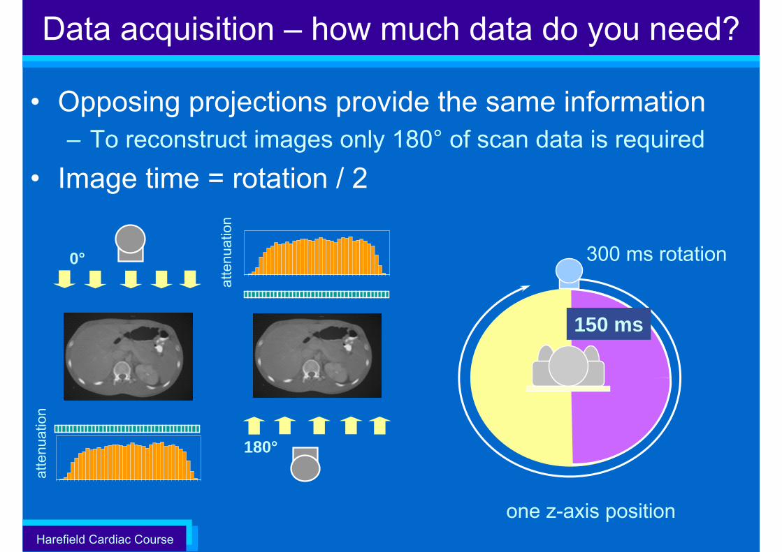
• Opposing projections provide the same information– To reconstruct images only 180° of scan data is required
• Image time = rotation / 2
Data acquisition – how much data do you need?at
tenu
atio
n
atte
nuat
ion
180°
0°
one z-axis position
150 ms
300 ms rotation
Harefield Cardiac Course
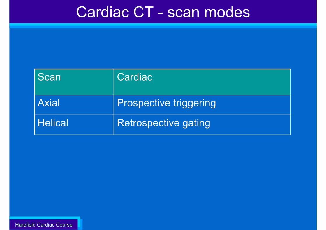
Cardiac CT - scan modes
Scan Cardiac
Axial Prospective triggering
Helical Retrospective gating
Harefield Cardiac Course
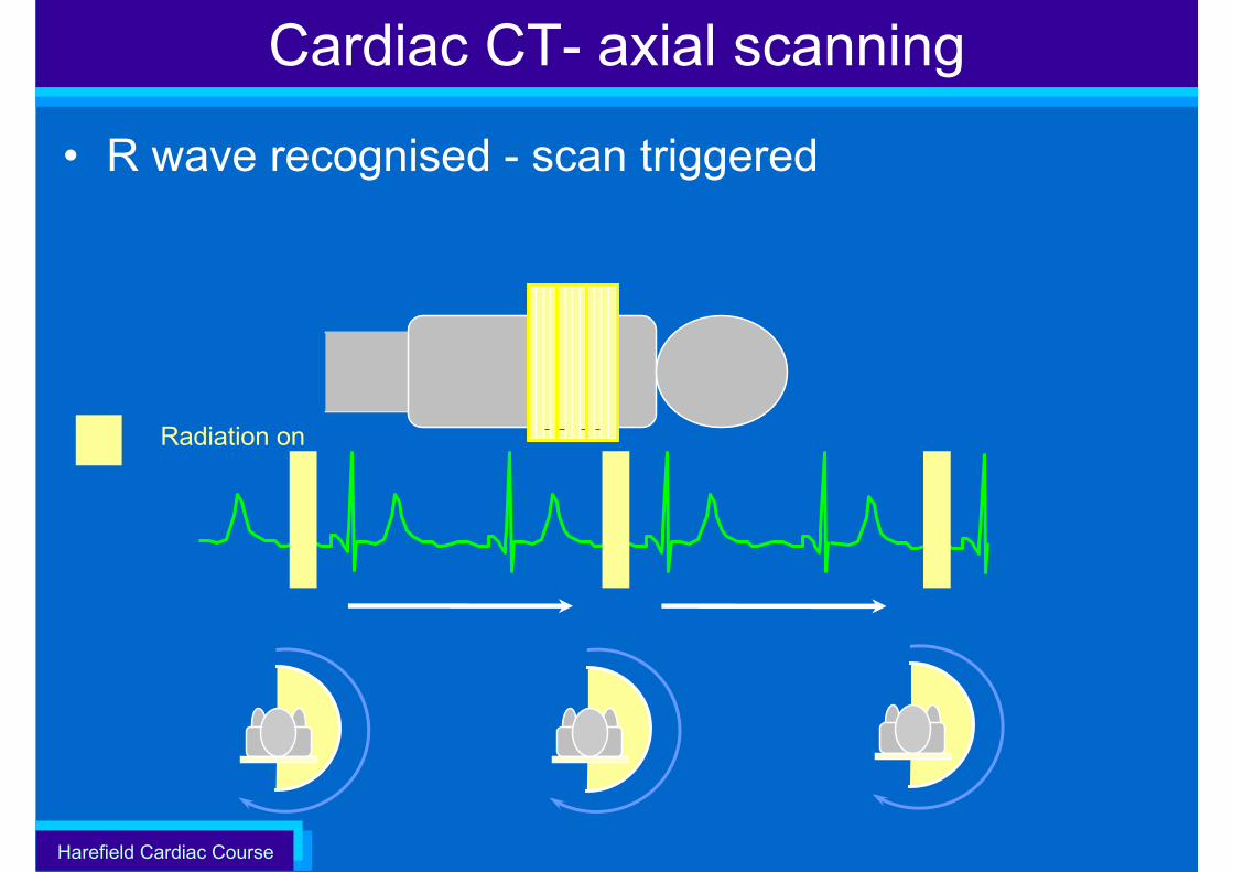
Cardiac CT- axial scanning
• R wave recognised - scan triggered
Radiation on
Harefield Cardiac Course
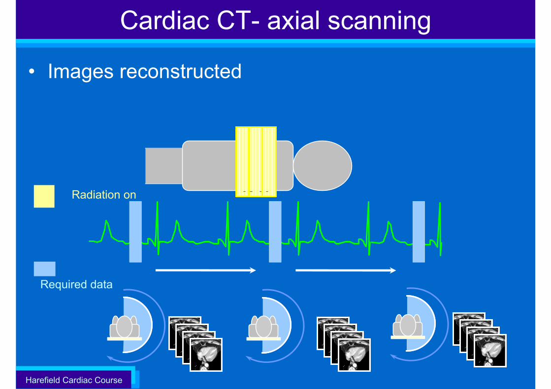
Cardiac CT- axial scanning
• Images reconstructed
Radiation on
Required data
Harefield Cardiac Course
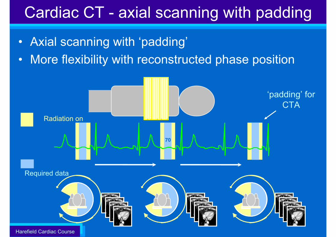
• Axial scanning with ‘padding’• More flexibility with reconstructed phase position
Cardiac CT - axial scanning with padding
‘padding’ for CTA
70
Radiation on
Required data
Harefield Cardiac Course
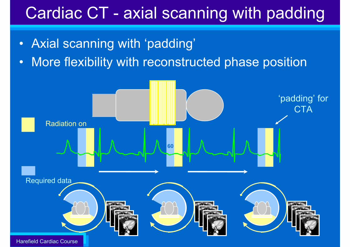
• Axial scanning with ‘padding’• More flexibility with reconstructed phase position
Cardiac CT - axial scanning with padding
‘padding’ for CTA
60
Radiation on
Required data
Harefield Cardiac Course
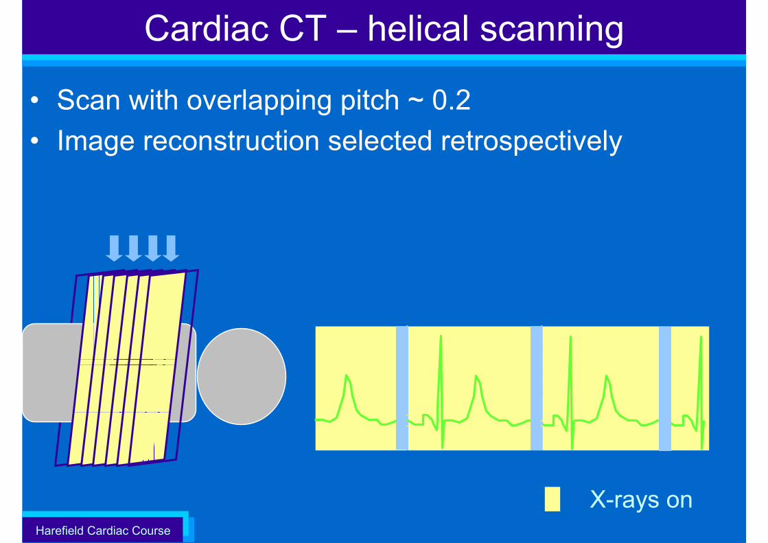
Cardiac CT – helical scanning
• Scan with overlapping pitch ~ 0.2• Image reconstruction selected retrospectively
X-rays on
Harefield Cardiac Course
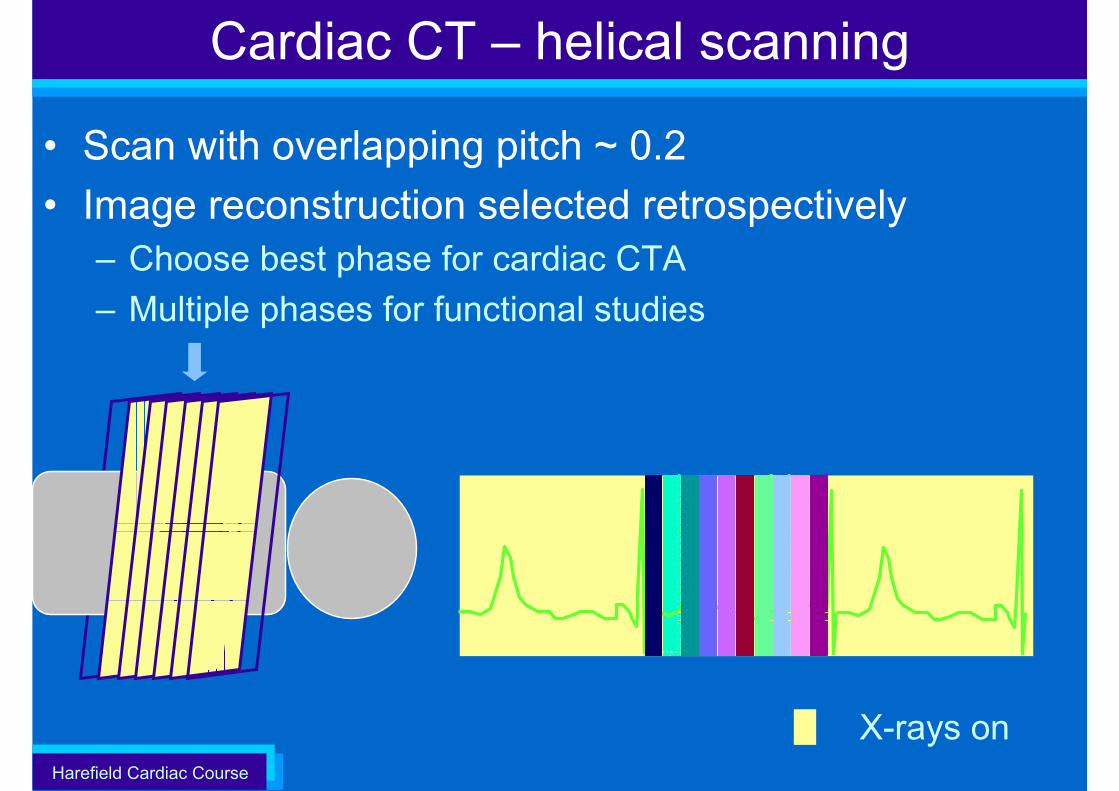
Cardiac CT – helical scanning
• Scan with overlapping pitch ~ 0.2• Image reconstruction selected retrospectively
– Choose best phase for cardiac CTA– Multiple phases for functional studies
X-rays on
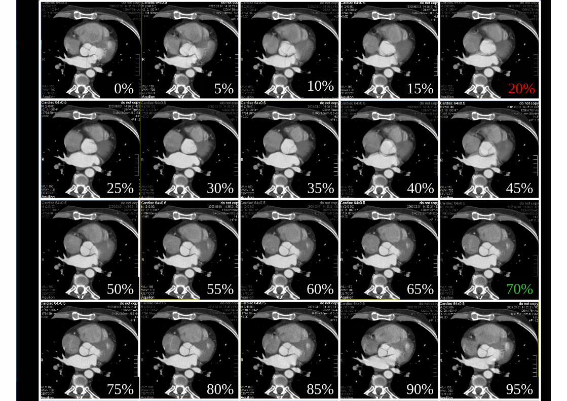
Harefield Cardiac Course 414180% 85%
55% 60% 65%
75%
50% 70%
95%90%
5% 15%0% 20%
30% 35% 40%25% 45%
10%
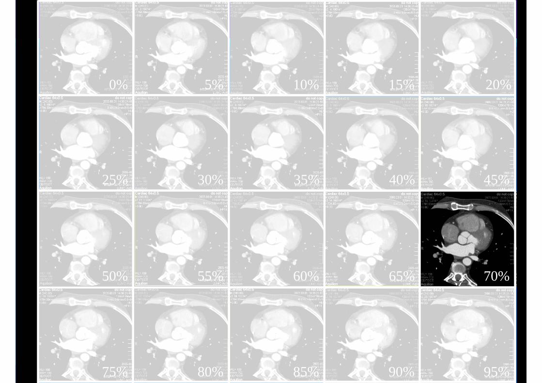
Harefield Cardiac Course 424290%75% 80% 85%
50% 55% 60% 65%
25% 30% 40%35%
0% 5% 10% 15% 20%
45%
70%
95%
Harefield Cardiac Course
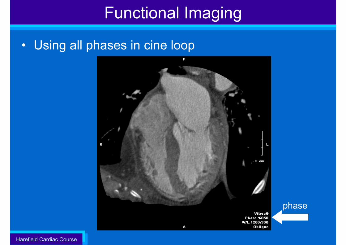
Functional Imaging
• Using all phases in cine loop
phase
Harefield Cardiac Course
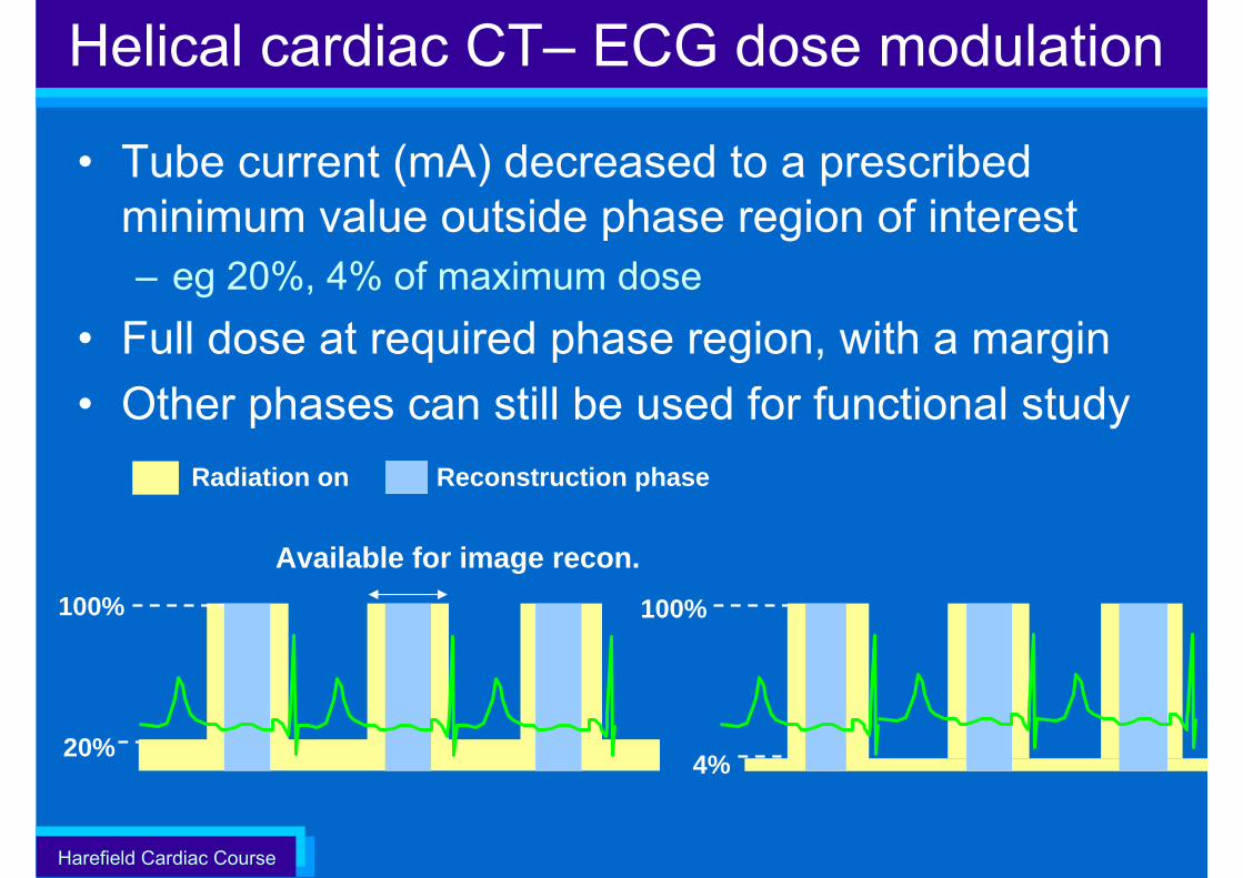
• Tube current (mA) decreased to a prescribed minimum value outside phase region of interest– eg 20%, 4% of maximum dose
• Full dose at required phase region, with a margin• Other phases can still be used for functional study
Radiation on
4%
100%
20%
Available for image recon.
Reconstruction phase
100%
Helical cardiac CT– ECG dose modulation
Harefield Cardiac Course
Helical pitch in cardiac scanning
Harefield Cardiac Course
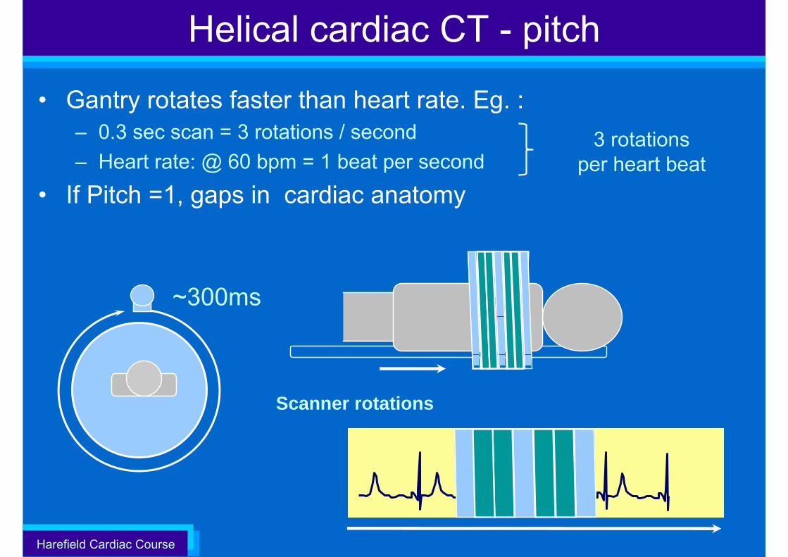
Helical cardiac CT - pitch
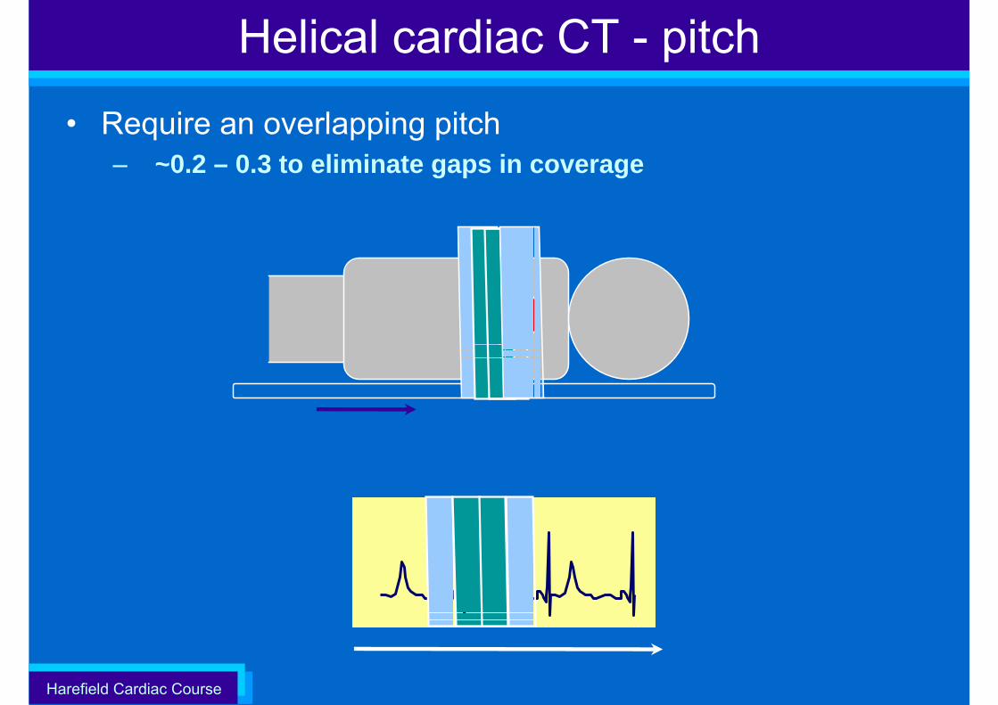
• Gantry rotates faster than heart rate. Eg. :– 0.3 sec scan = 3 rotations / second– Heart rate: @ 60 bpm = 1 beat per second
• If Pitch =1, gaps in cardiac anatomy
Scanner rotations
~300ms
3 rotations per heart beat
Harefield Cardiac Course
Helical cardiac CT - pitch
• Require an overlapping pitch– ~0.2 – 0.3 to eliminate gaps in coverage
Harefield Cardiac Course
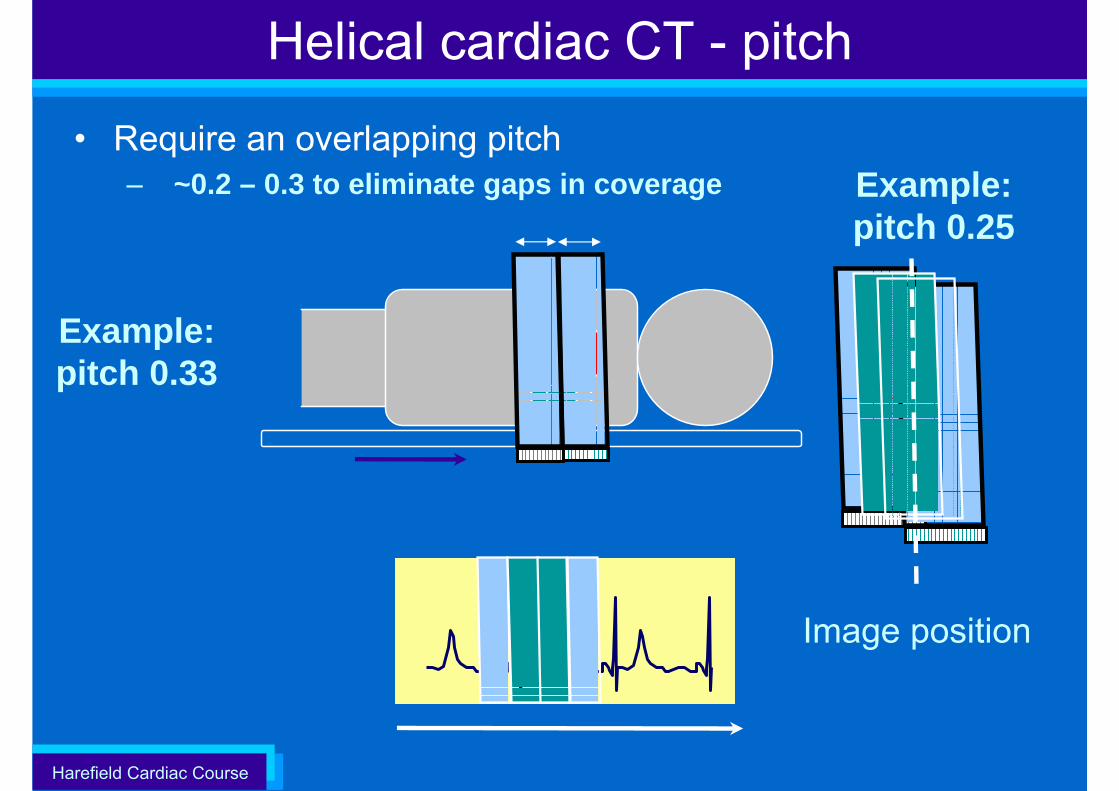
• Require an overlapping pitch– ~0.2 – 0.3 to eliminate gaps in coverage
Helical cardiac CT - pitch
Example: pitch 0.33
Example: pitch 0.25
Image position
Harefield Cardiac Course
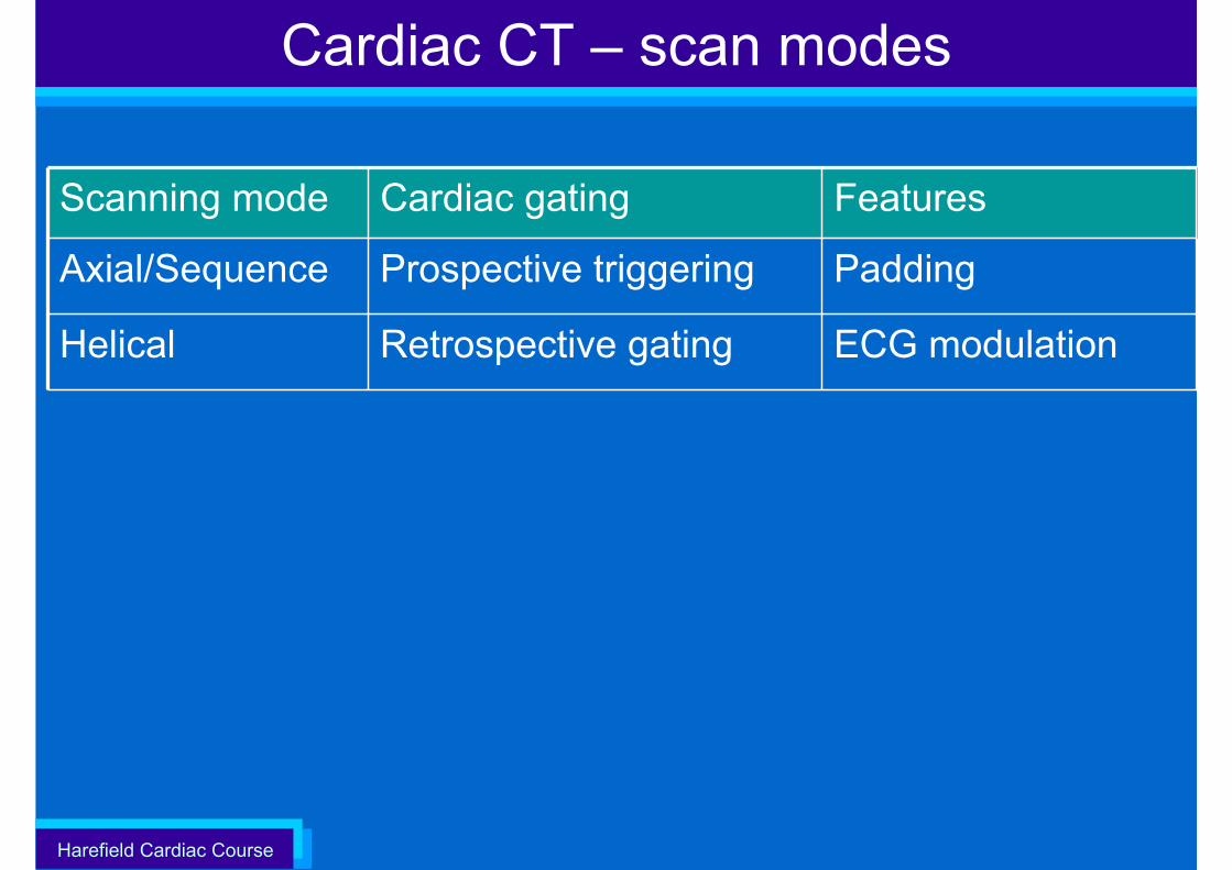
Cardiac CT – scan modes
Scanning mode Cardiac gating Features
Axial/Sequence Prospective triggering Padding
Helical Retrospective gating ECG modulation
Harefield Cardiac Course
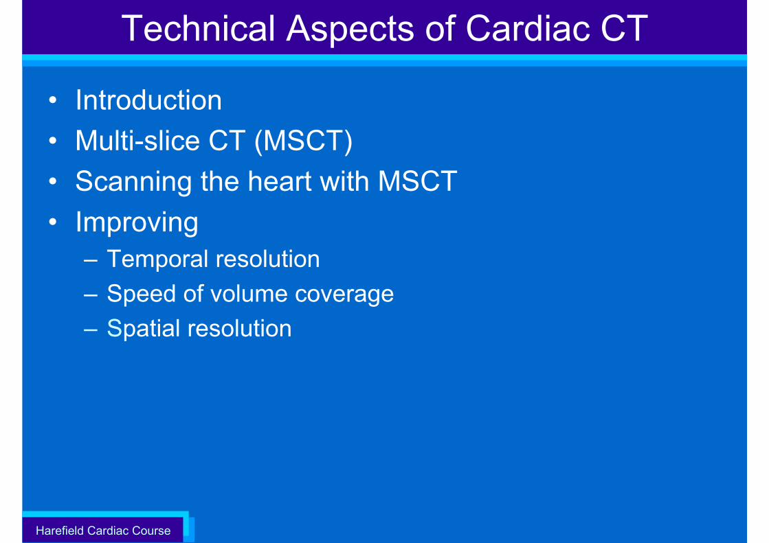
Technical Aspects of Cardiac CT
• Introduction• Multi-slice CT (MSCT)• Scanning the heart with MSCT• Improving
– Temporal resolution– Speed of volume coverage– Spatial resolution
Harefield Cardiac Course
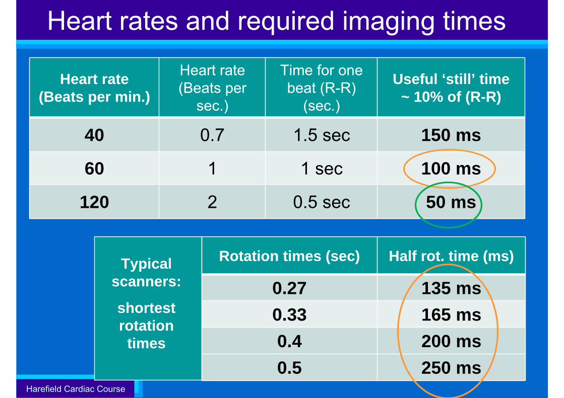
Heart rates and required imaging times
Heart rate(Beats per min.)
Heart rate(Beats per
sec.)
Time for one beat (R-R)
(sec.)
Useful ‘still’ time~ 10% of (R-R)
40 0.7 1.5 sec 150 ms
60 1 1 sec 100 ms
120 2 0.5 sec 50 ms
Rotation times (sec) Half rot. time (ms)
0.27 135 ms0.33 165 ms0.4 200 ms0.5 250 ms
Typical scanners:
shortest rotation times
Harefield Cardiac Course
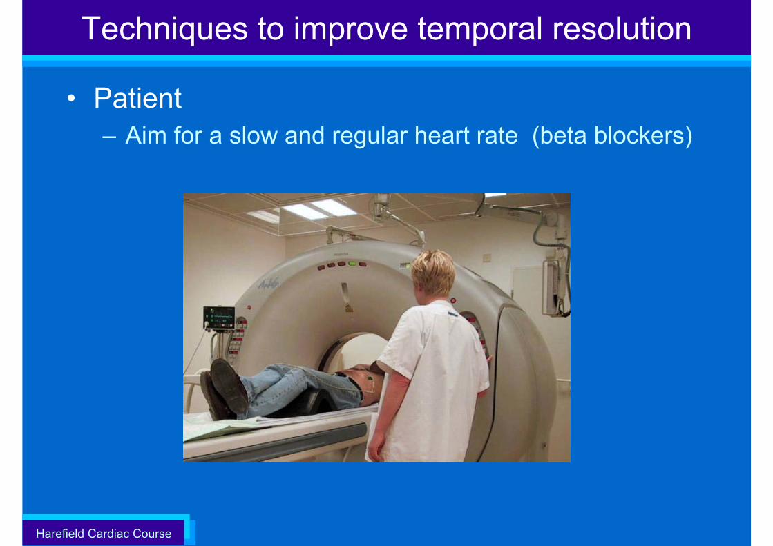
Techniques to improve temporal resolution
• Patient – Aim for a slow and regular heart rate (beta blockers)
Harefield Cardiac Course
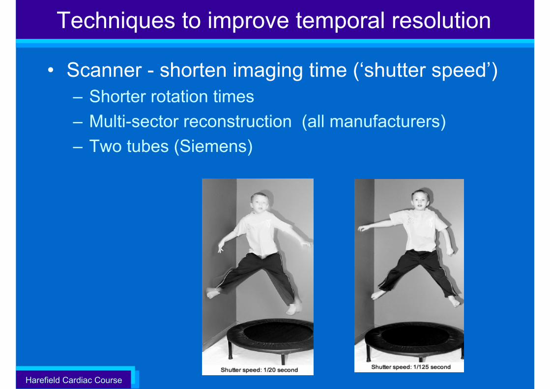
Techniques to improve temporal resolution
• Scanner - shorten imaging time (‘shutter speed’)– Shorter rotation times– Multi-sector reconstruction (all manufacturers)– Two tubes (Siemens)
Harefield Cardiac Course
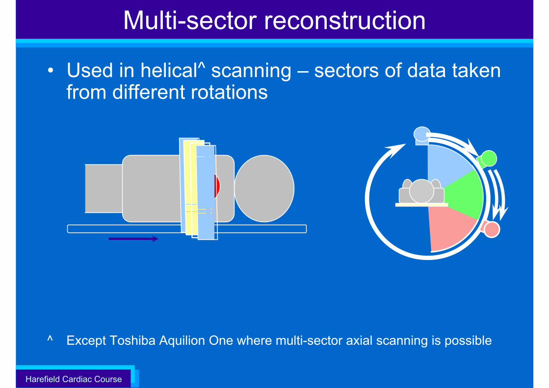
• Used in helical^ scanning – sectors of data taken from different rotations
^ Except Toshiba Aquilion One where multi-sector axial scanning is possible
Multi-sector reconstruction
Harefield Cardiac Course
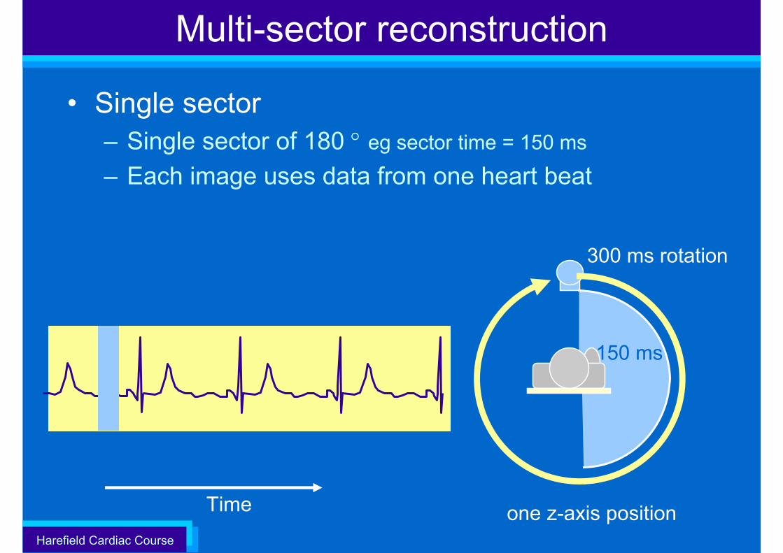
• Single sector– Single sector of 180 ° eg sector time = 150 ms
– Each image uses data from one heart beat
Multi-sector reconstruction
Time one z-axis position
150 ms
300 ms rotation
Harefield Cardiac Course
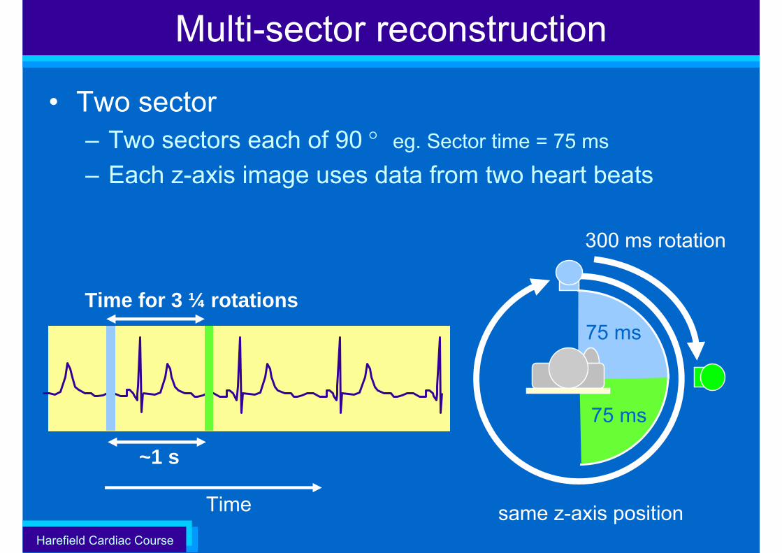
• Two sector– Two sectors each of 90 ° eg. Sector time = 75 ms
– Each z-axis image uses data from two heart beats
75 ms
Multi-sector reconstruction
Time
Time for 3 ¼ rotations
same z-axis position
75 ms
300 ms rotation
~1 s
Harefield Cardiac Course
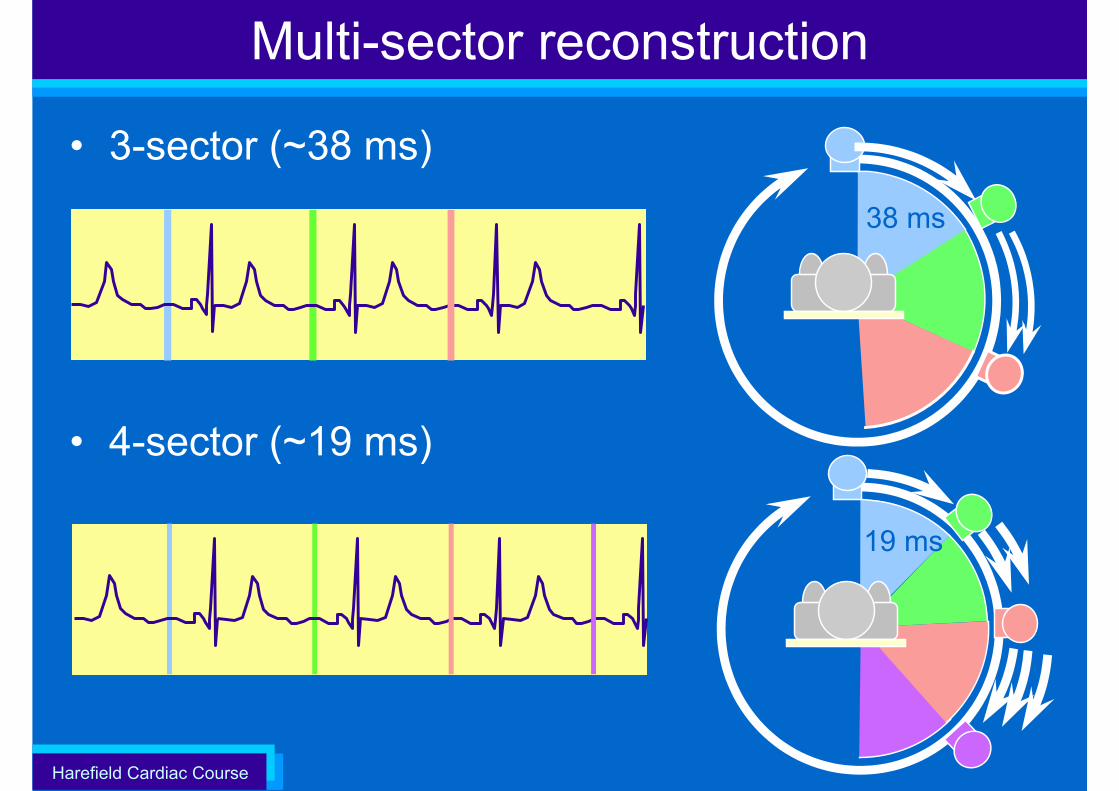
Multi-sector reconstruction
• 3-sector (~38 ms)
• 4-sector (~19 ms)
38 ms
19 ms
Harefield Cardiac Course
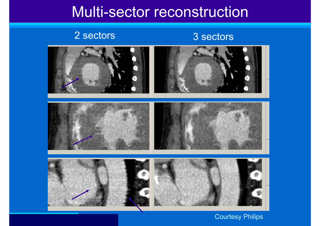
2 sectors 3 sectors
Multi-sector reconstruction
Courtesy Philips
Harefield Cardiac Course
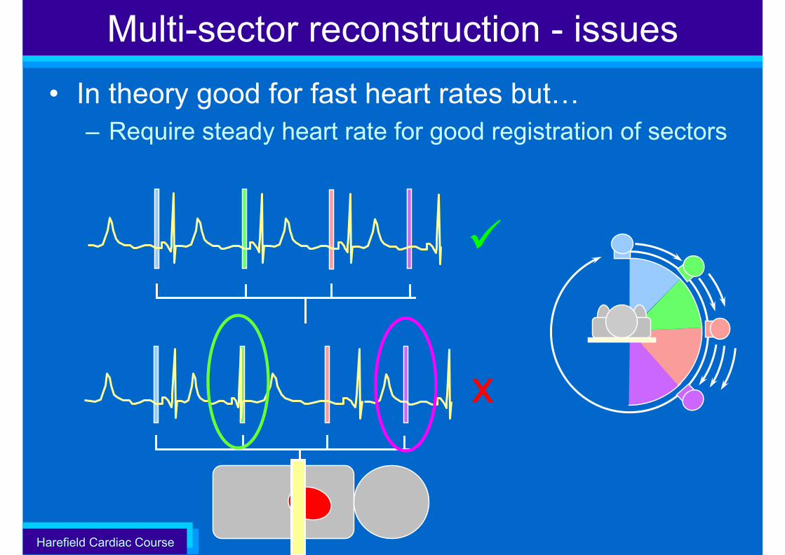
Multi-sector reconstruction - issues
• In theory good for fast heart rates but…– Require steady heart rate for good registration of sectors
x
Harefield Cardiac Course
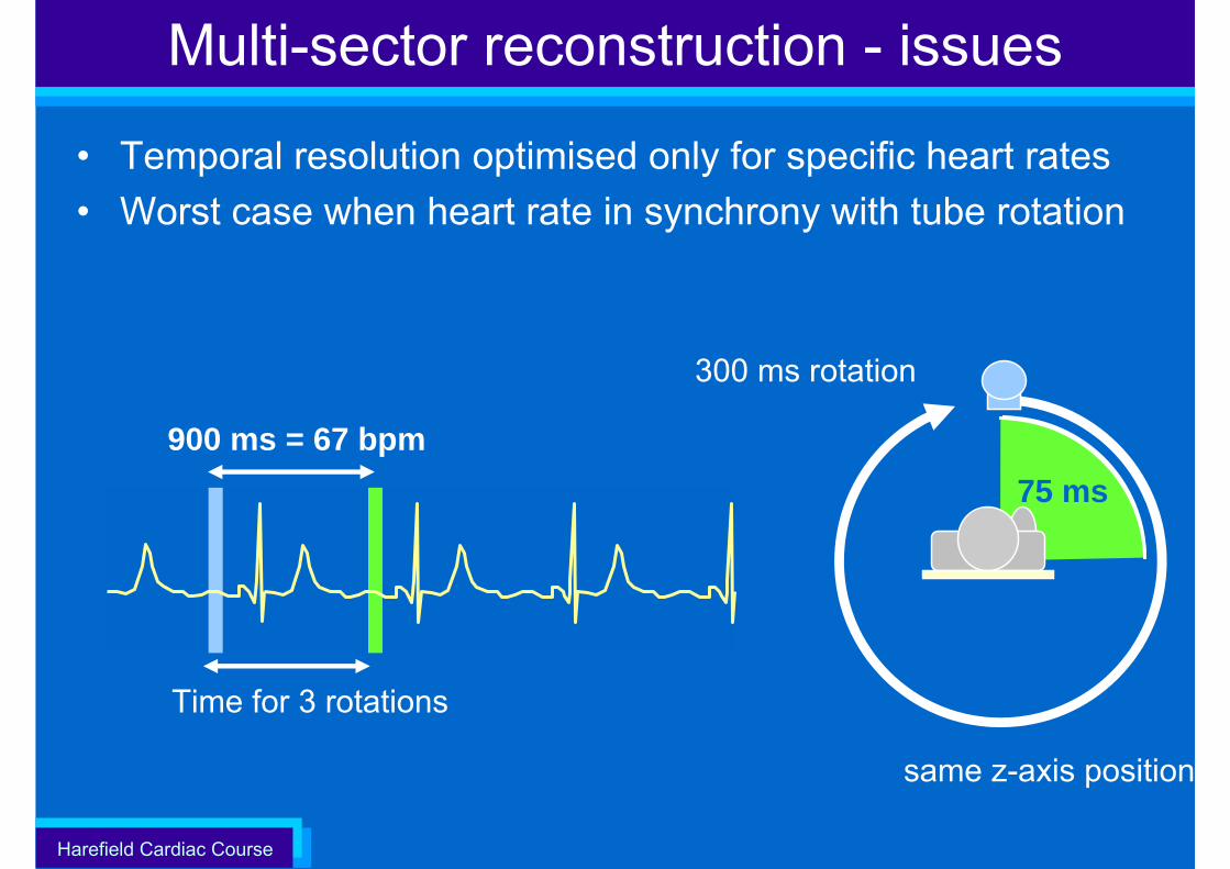
Multi-sector reconstruction - issues
• Temporal resolution optimised only for specific heart rates• Worst case when heart rate in synchrony with tube rotation
Time for 3 rotations
same z-axis position
75 ms
300 ms rotation
900 ms = 67 bpm
Harefield Cardiac Course
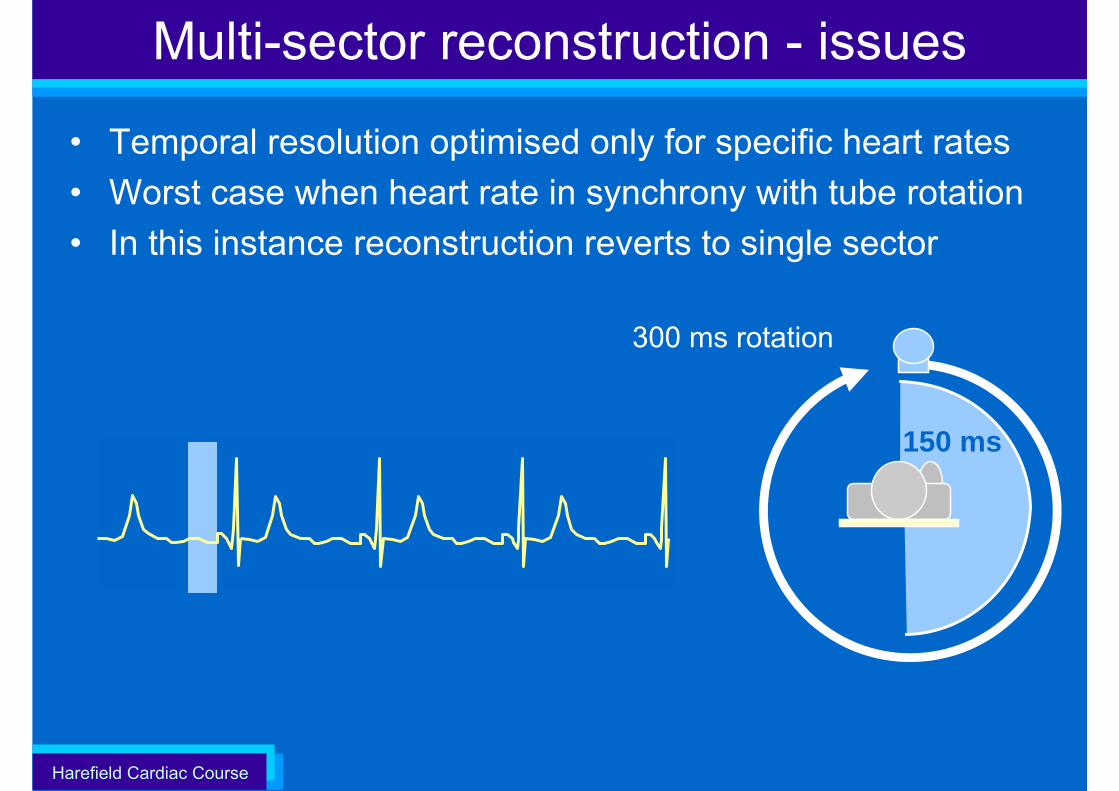
Multi-sector reconstruction - issues
• Temporal resolution optimised only for specific heart rates• Worst case when heart rate in synchrony with tube rotation• In this instance reconstruction reverts to single sector
150 ms
300 ms rotation
Harefield Cardiac Course
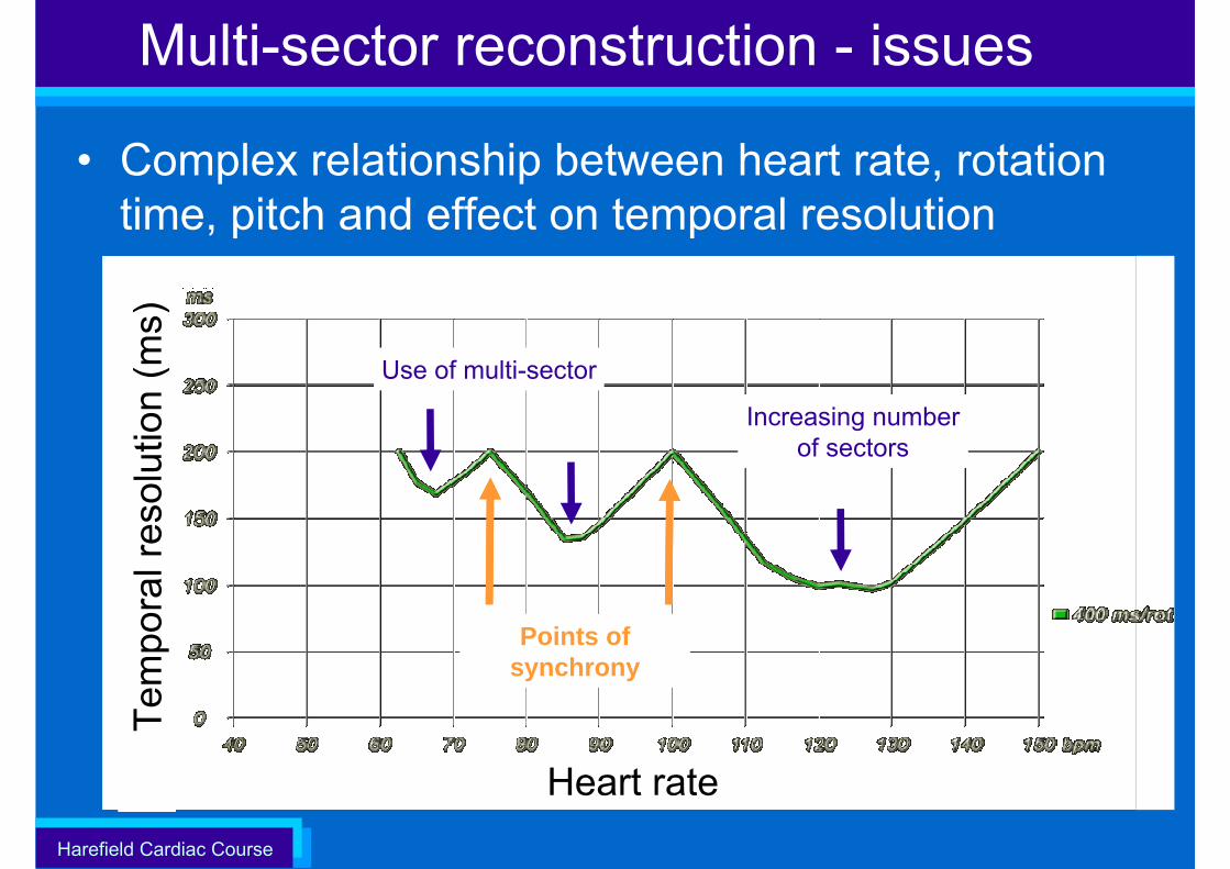
Multi-sector reconstruction - issues
• Complex relationship between heart rate, rotation time, pitch and effect on temporal resolution
Heart rate
Sec
tor w
indo
w (m
s)
Increasing number of sectors
Tem
pora
l res
olut
ion
(ms)
Points of synchrony
Use of multi-sector
Harefield Cardiac Course
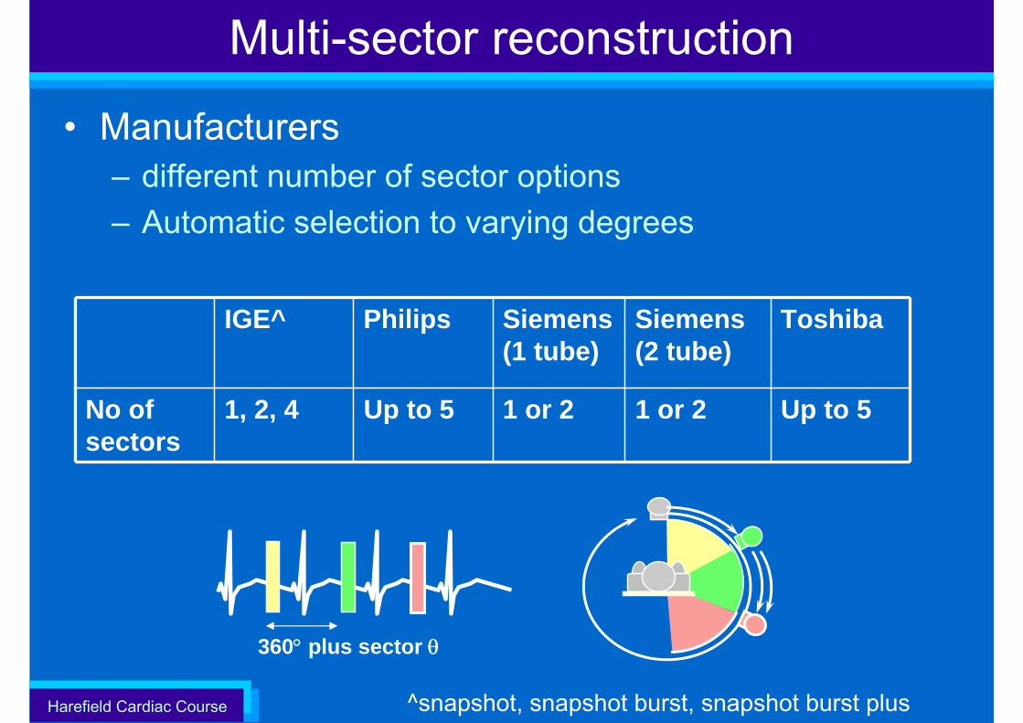
Multi-sector reconstruction
• Manufacturers– different number of sector options– Automatic selection to varying degrees
IGE^ Philips Siemens(1 tube)
Siemens (2 tube)
Toshiba
No of sectors
1, 2, 4 Up to 5 1 or 2 1 or 2 Up to 5
360° plus sector θ
^snapshot, snapshot burst, snapshot burst plus

Harefield Cardiac Course Courtesy Siemens
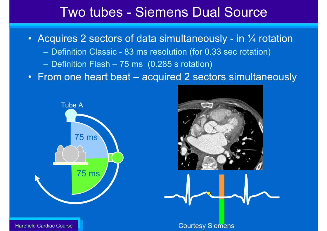
Two tubes - Siemens Dual Source
• Acquires 2 sectors of data simultaneously - in ¼ rotation– Definition Classic - 83 ms resolution (for 0.33 sec rotation)– Definition Flash – 75 ms (0.285 s rotation)
Harefield Cardiac Course Courtesy Siemens
Two tubes - Siemens Dual Source
• Acquires 2 sectors of data simultaneously - in ¼ rotation– Definition Classic - 83 ms resolution (for 0.33 sec rotation)– Definition Flash – 75 ms (0.285 s rotation)
• From one heart beat – acquired 2 sectors simultaneously
Tube A
75 ms
75 ms
Harefield Cardiac Course
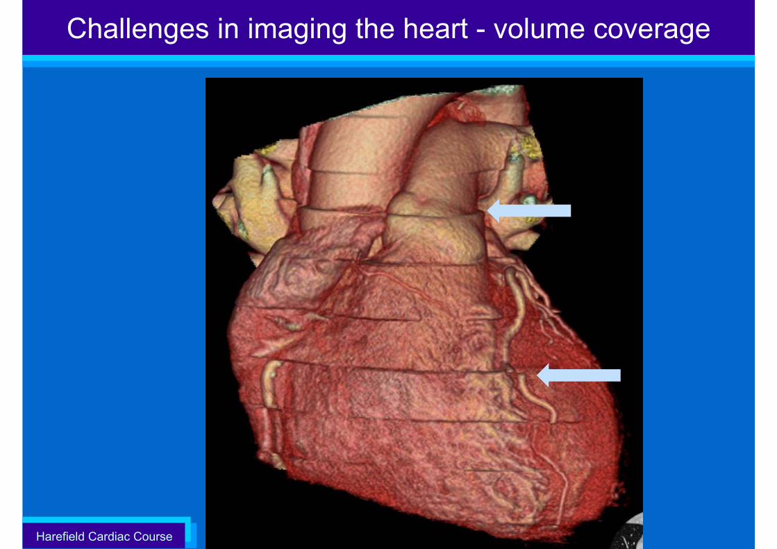
Challenges in imaging the heart - volume coverage
Harefield Cardiac Course
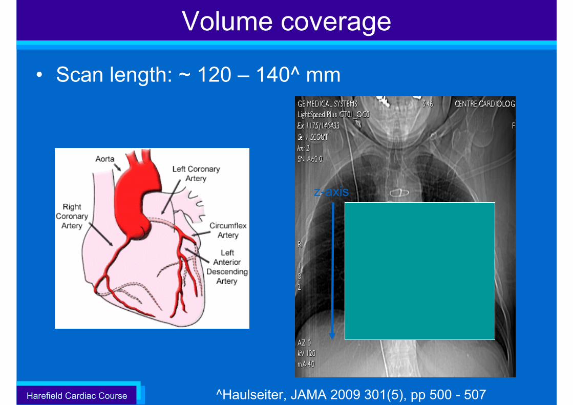
Volume coverage
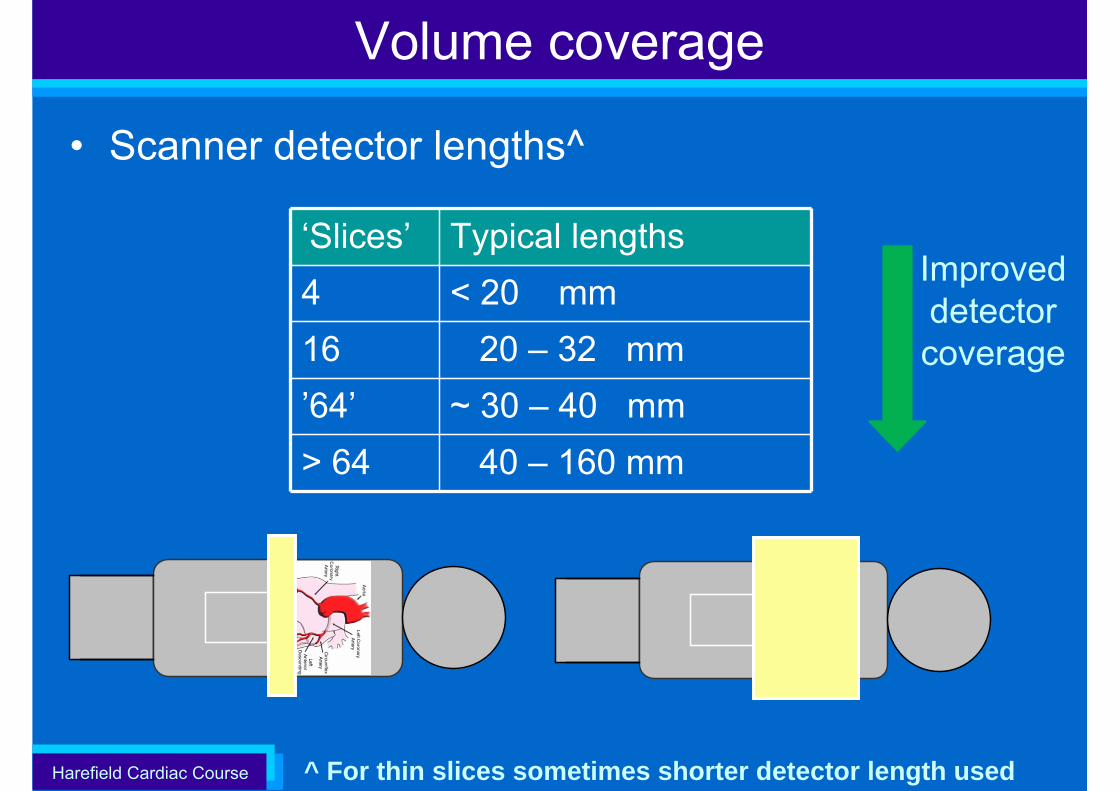
• Scan length: ~ 120 – 140^ mm
z-axis
^Haulseiter, JAMA 2009 301(5), pp 500 - 507
Harefield Cardiac Course
Volume coverage
^ For thin slices sometimes shorter detector length used
‘Slices’ Typical lengths4 < 20 mm16 20 – 32 mm’64’ ~ 30 – 40 mm> 64 40 – 160 mm
• Scanner detector lengths^
Improved detector coverage
Harefield Cardiac Course
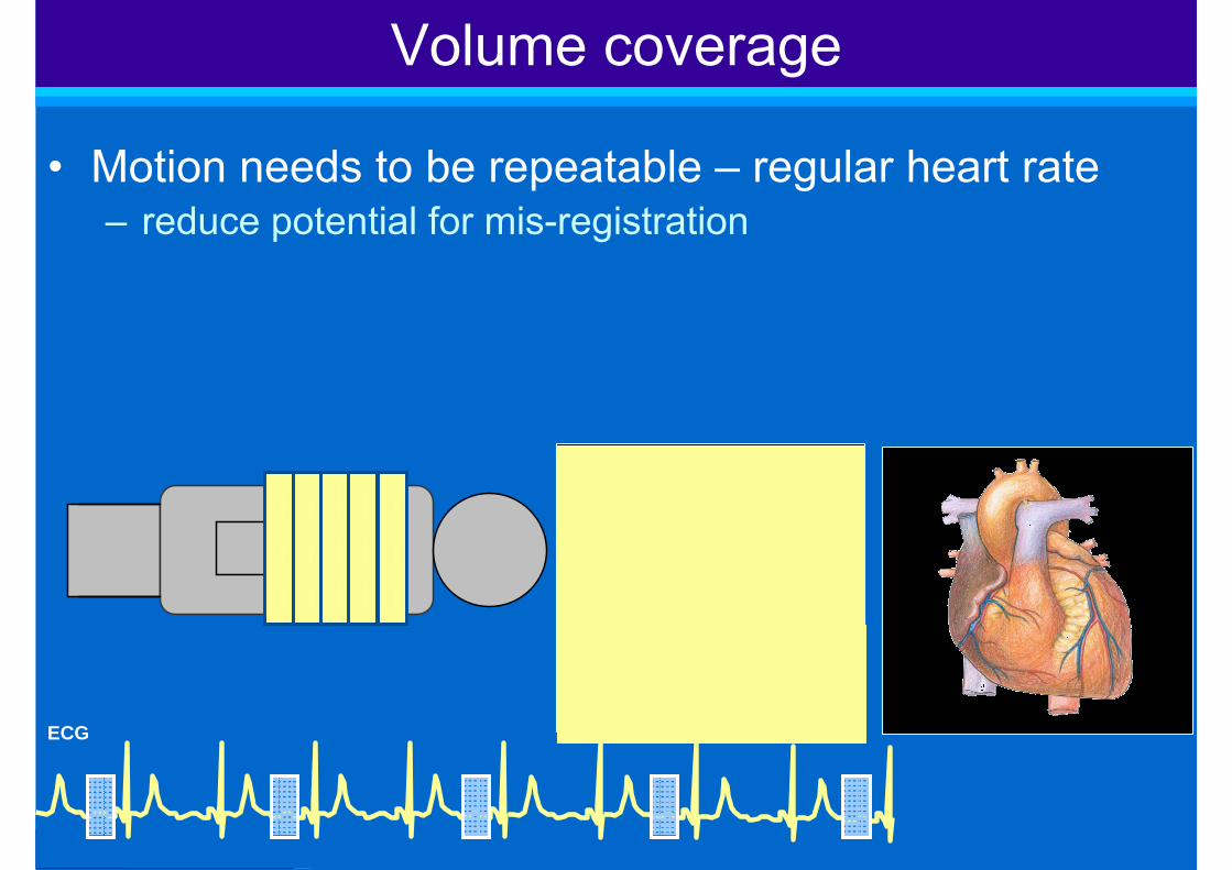
• Motion needs to be repeatable – regular heart rate– reduce potential for mis-registration
Volume coverage
ECG
iii
iii
iii
iii
iii
Harefield Cardiac Course
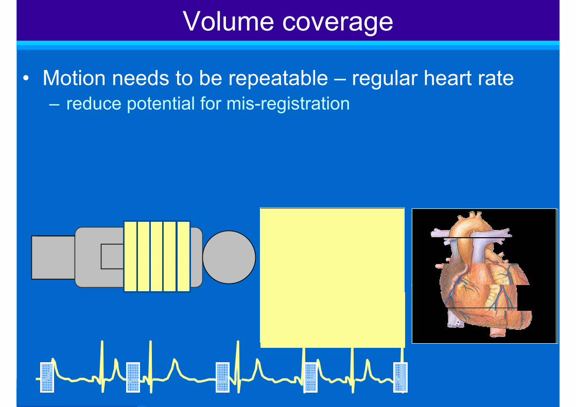
• Motion needs to be repeatable – regular heart rate– reduce potential for mis-registration
Volume coverage
iii
iii
iii
iii
iii
Harefield Cardiac Course
Challenges in imaging the heart - volume coverage
Harefield Cardiac Course
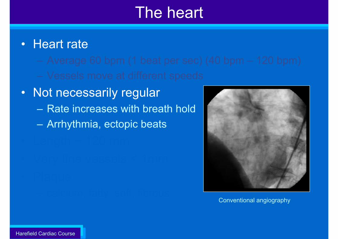
The heart
• Heart rate– Average 60 bpm (1 beat per sec) (40 bpm – 120 bpm) – Vessels move at different speeds
• Not necessarily regular– Rate increases with breath hold– Arrhythmia, ectopic beats
• Length ~ 120 mm• Very fine vessels < 1mm• Plaque
– calcium, fatty, soft, fibrousConventional angiography
Harefield Cardiac Course
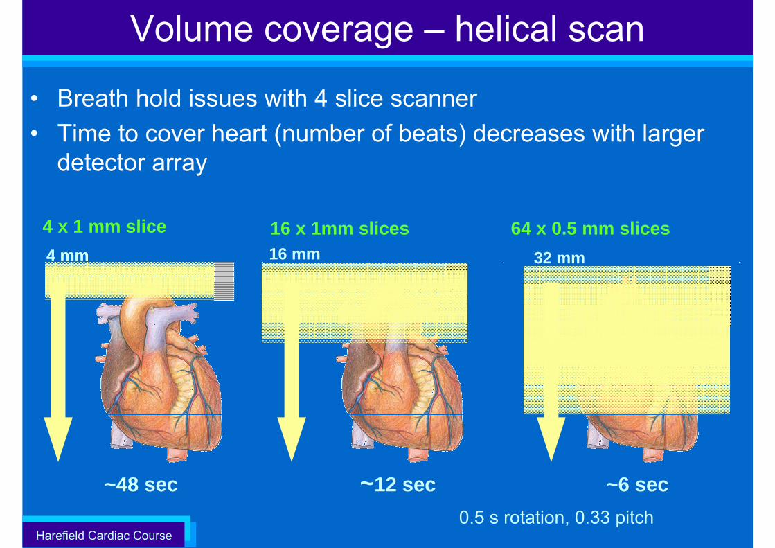
• Breath hold issues with 4 slice scanner• Time to cover heart (number of beats) decreases with larger
detector array
Volume coverage – helical scan
16 x 1mm slices 64 x 0.5 mm slices
~48 sec ~12 sec ~6 sec
4 x 1 mm slice
0.5 s rotation, 0.33 pitch
4 mm 16 mm 32 mm4 mm
Harefield Cardiac Course
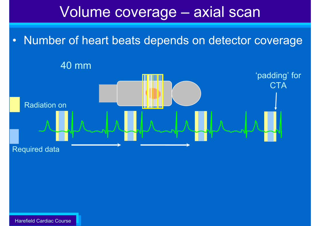
• Number of heart beats depends on detector coverage
‘padding’ for CTA
Volume coverage – axial scan
Radiation on
Required data
40 mm
Harefield Cardiac Course
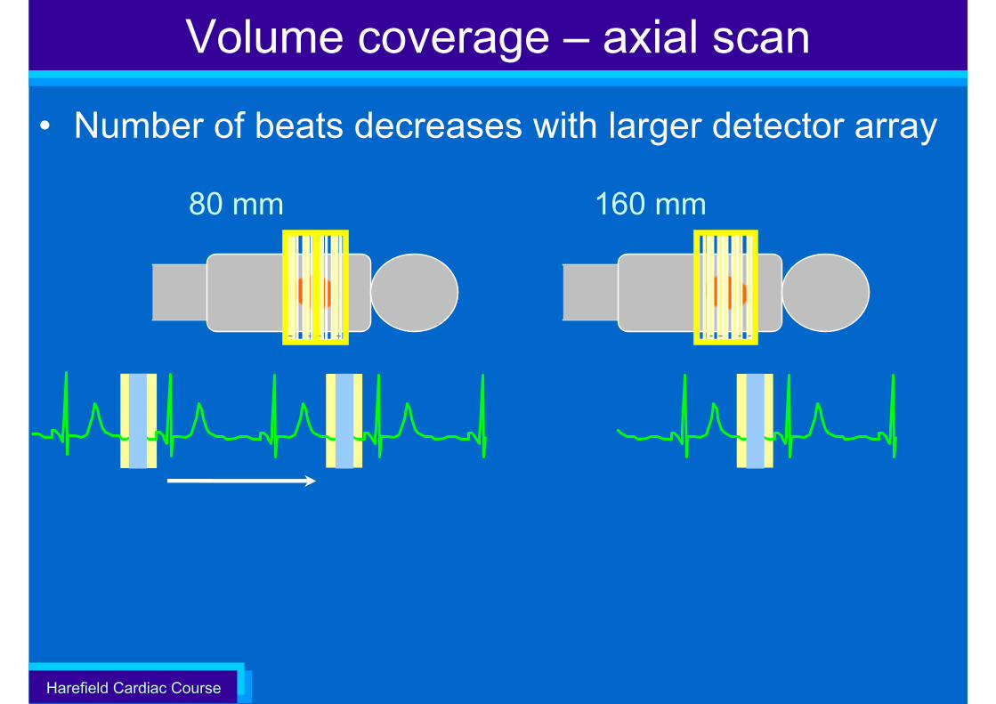
Volume coverage – axial scan
• Number of beats decreases with larger detector array
80 mm 160 mm
Harefield Cardiac Course
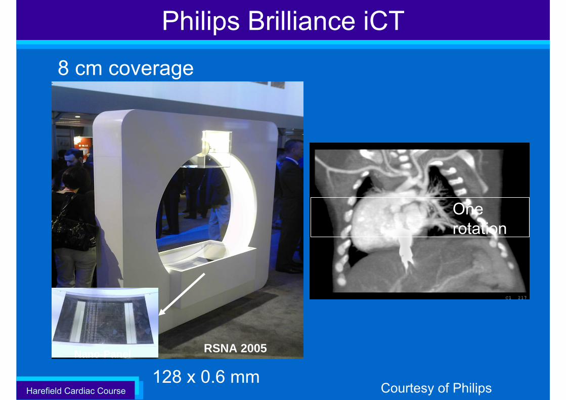
8 cm coverage
128 x 0.6 mm
One rotation
RSNA 2005Nano-Panel
Philips Brilliance iCT
Courtesy of Philips
Harefield Cardiac Course
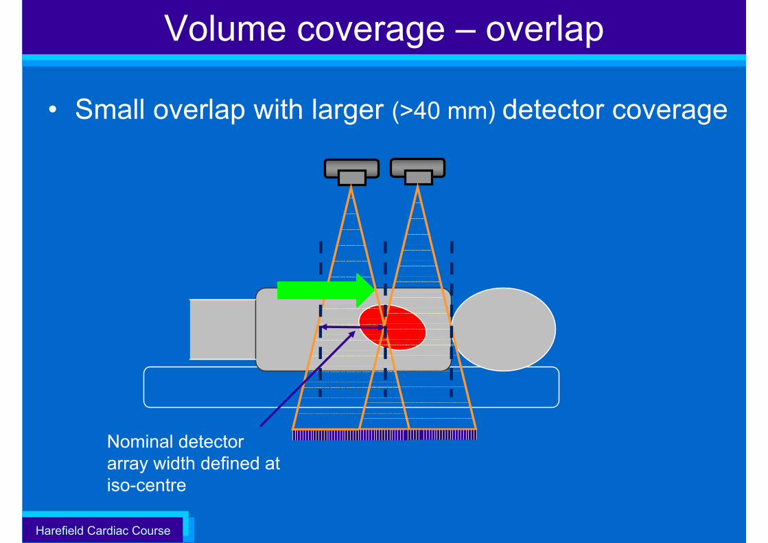
Volume coverage – overlap
• Small overlap with larger (>40 mm) detector coverage
Nominal detector array width defined at iso-centre
Harefield Cardiac Course
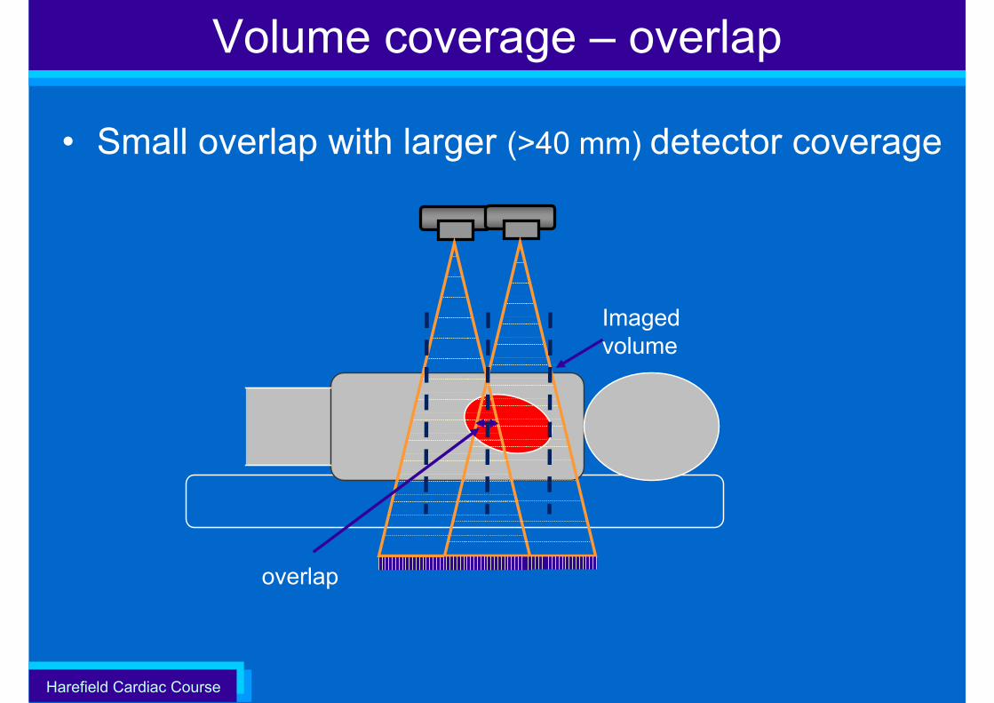
Volume coverage – overlap
• Small overlap with larger (>40 mm) detector coverage
Imaged volume
overlap
Harefield Cardiac Course
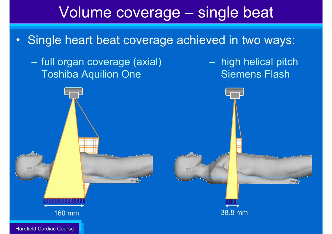
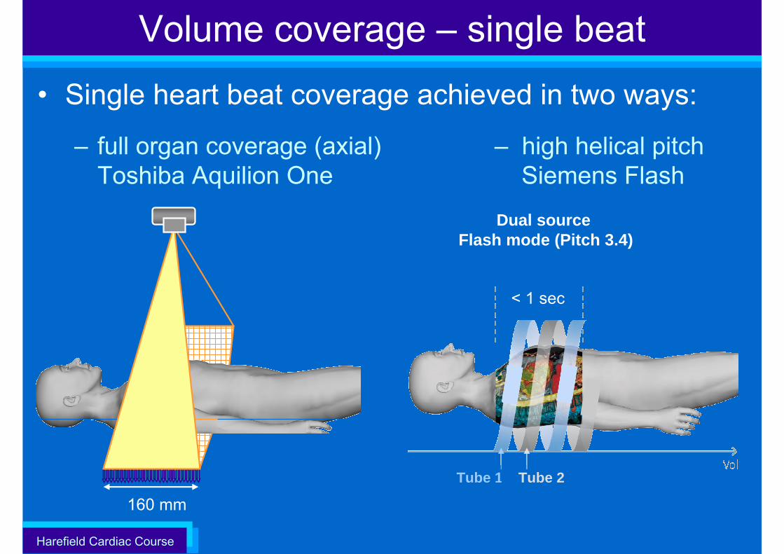
• Single heart beat coverage achieved in two ways:
– full organ coverage (axial) – high helical pitchToshiba Aquilion One Siemens Flash
160 mm
Volume coverage – single beat
38.8 mm
Harefield Cardiac Course
160 mm
Volume coverage – single beat
• Single heart beat coverage achieved in two ways:
– full organ coverage (axial) – high helical pitchToshiba Aquilion One Siemens Flash
< 1 sec
Tube 1 Tube 2
Dual source Flash mode (Pitch 3.4)
Harefield Cardiac Course
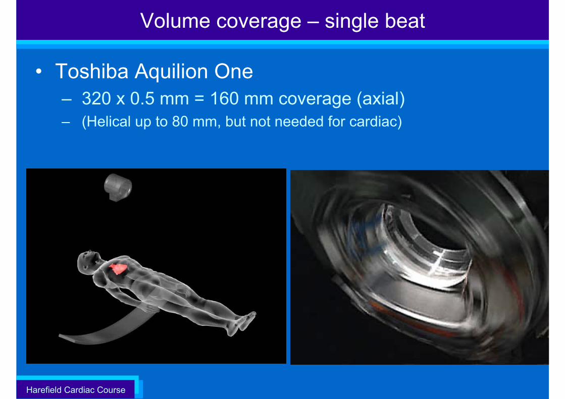
Volume coverage – single beat
• Toshiba Aquilion One– 320 x 0.5 mm = 160 mm coverage (axial)– (Helical up to 80 mm, but not needed for cardiac)
Harefield Cardiac Course85
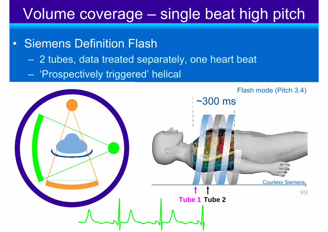
• Siemens Definition Flash– 2 tubes, data treated separately, one heart beat– ‘Prospectively triggered’ helical
Volume coverage – single beat high pitch
Courtesy Siemens
~300 ms
Tube 2 Tube 1
Flash mode (Pitch 3.4)

Harefield Cardiac Course
• Siemens Definition Flash – high pitch helical (pitch 3.4), each image 75 ms– phase difference between first and last ~ 300 ms– only suitable for regular heart rates < 65 bpm
Volume coverage – single beat high pitch
R
Acquired slices(each at 75 ms)
R
Radiation on
~300 ms
< 1 sec
Tube 1 Tube 2
Flash mode (Pitch 3.4)
Harefield Cardiac Course
• Improved temporal resolution– Fast scan speeds, multi-sector reconstruction, dual tube
• Fast volume coverage – Larger detector arrays– High pitch scanning (‘Flash’)
Cardiac CT

Harefield Cardiac Course
Technical Aspects of Cardiac CT
• Introduction• Multi-slice CT (MSCT)• Scanning the heart with MSCT• Improving
– Temporal resolution– Volume coverage– Spatial resolution
Harefield Cardiac Course
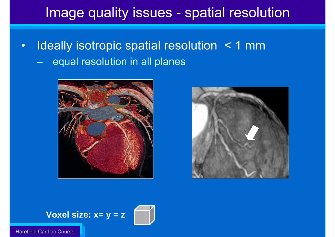
Image quality issues - spatial resolution
• Ideally isotropic spatial resolution < 1 mm– equal resolution in all planes
Voxel size: x= y = z
Harefield Cardiac Course
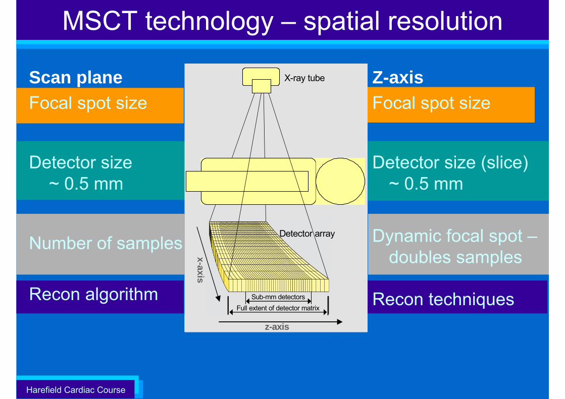
MSCT technology – spatial resolution
z-axis
x-axis
X-ray tube
Detector array
z-axis
x-axis
z-axis
x-axis
X-ray tube
Detector array
Sub-mm detectorsFull extent of detector matrix
Z-axisFocal spot size
Detector size (slice) ~ 0.5 mm
Dynamic focal spot –doubles samples
Recon techniques
Scan planeFocal spot size
Detector size ~ 0.5 mm
Number of samples
Recon algorithm
Harefield Cardiac Course
z-axis
x-axis
X-ray tube
Detector array
z-axis
x-axis
z-axis
x-axis
X-ray tube
Detector array
Sub-mm detectorsFull extent of detector matrix
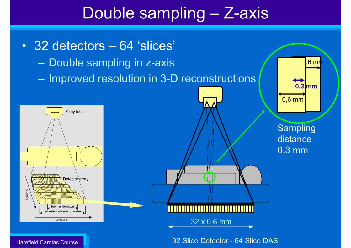
Double sampling – Z-axis
• 32 detectors – 64 ‘slices’– Double sampling in z-axis– Improved resolution in 3-D reconstructions
32 Slice Detector - 64 Slice DAS
0,6 mm
32 x 0.6 mm
0,6 mm
Sampling distance 0.3 mm
0.3 mm
Harefield Cardiac Course
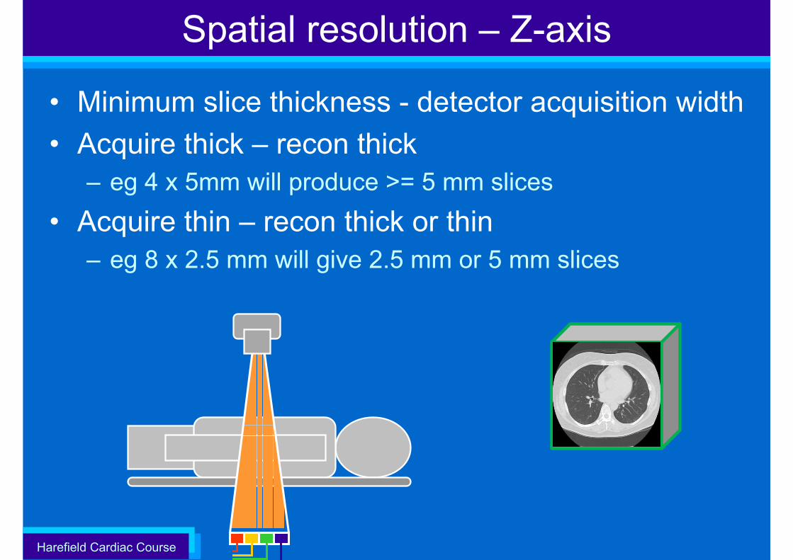
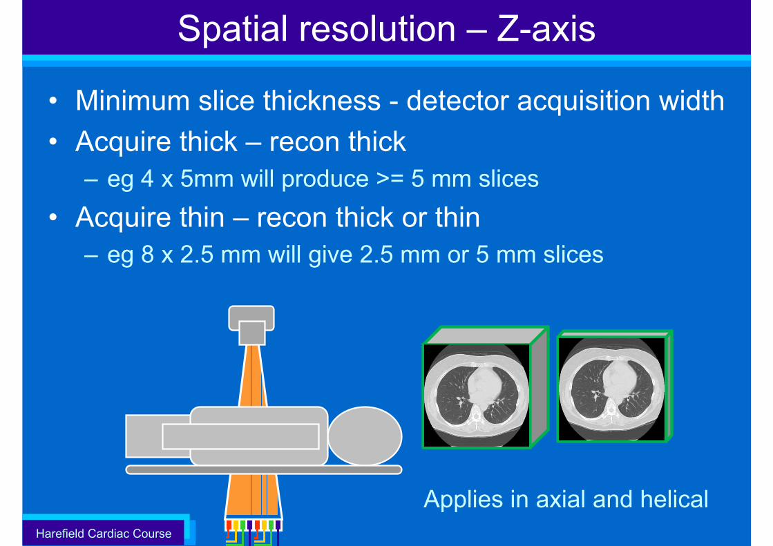
• Minimum slice thickness - detector acquisition width• Acquire thick – recon thick
– eg 4 x 5mm will produce >= 5 mm slices • Acquire thin – recon thick or thin
– eg 8 x 2.5 mm will give 2.5 mm or 5 mm slices
Spatial resolution – Z-axis
Harefield Cardiac Course
Spatial resolution – Z-axis
• Minimum slice thickness - detector acquisition width• Acquire thick – recon thick
– eg 4 x 5mm will produce >= 5 mm slices • Acquire thin – recon thick or thin
– eg 8 x 2.5 mm will give 2.5 mm or 5 mm slices
Applies in axial and helical
Harefield Cardiac Course
Spatial resolution – Z-axis
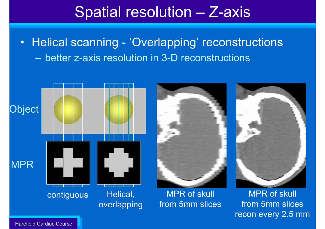
• Helical scanning - ‘Overlapping’ reconstructions– better z-axis resolution in 3-D reconstructions
MPR of skull from 5mm slices
MPR of skull from 5mm slices
recon every 2.5 mm
contiguous Helical, overlapping
MPR
Object
Harefield Cardiac Course
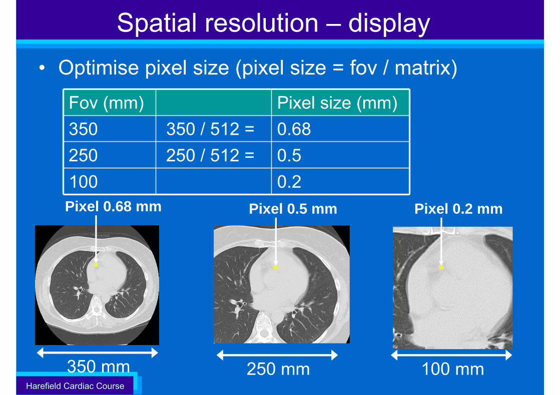
Spatial resolution – display• Optimise pixel size (pixel size = fov / matrix)
350 mm
Pixel 0.68 mm
250 mm
Pixel 0.5 mm
Fov (mm) Pixel size (mm)350 350 / 512 = 0.68250 250 / 512 = 0.5100 0.2
100 mm
Pixel 0.2 mm
Harefield Cardiac Course
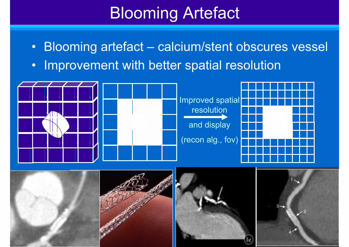
• Blooming artefact – calcium/stent obscures vessel• Improvement with better spatial resolution
96
Blooming Artefact
Improved spatial resolution
and display
(recon alg., fov)
Harefield Cardiac Course
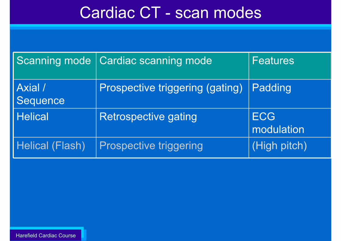
Cardiac CT - scan modes
Scanning mode Cardiac scanning mode Features
Axial / Sequence
Prospective triggering (gating) Padding
Helical Retrospective gating ECG modulation
Helical (Flash) Prospective triggering (High pitch)
Harefield Cardiac Course
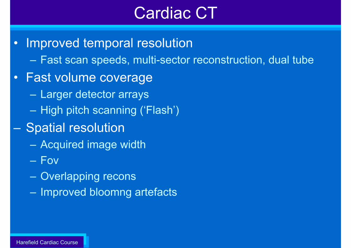
• Improved temporal resolution– Fast scan speeds, multi-sector reconstruction, dual tube
• Fast volume coverage – Larger detector arrays– High pitch scanning (‘Flash’)
– Spatial resolution– Acquired image width– Fov– Overlapping recons– Improved bloomng artefacts
Cardiac CT
Harefield Cardiac Course
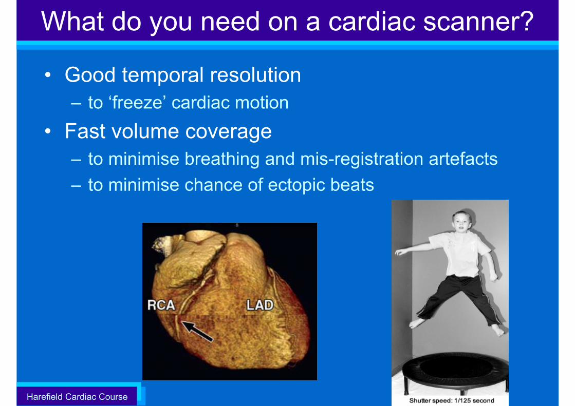
What do you need on a cardiac scanner?
• Good temporal resolution– to ‘freeze’ cardiac motion
• Fast volume coverage – to minimise breathing and mis-registration artefacts– to minimise chance of ectopic beats
Harefield Cardiac Course
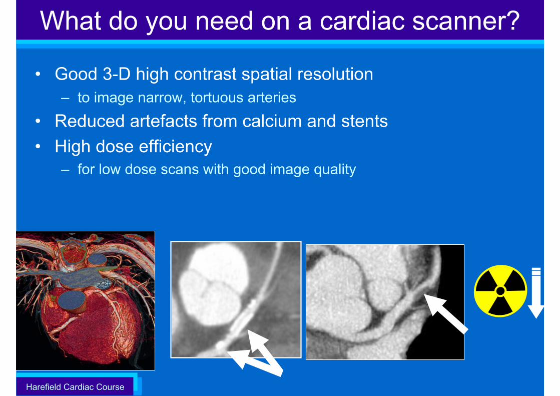
What do you need on a cardiac scanner?
• Good 3-D high contrast spatial resolution– to image narrow, tortuous arteries
• Reduced artefacts from calcium and stents• High dose efficiency
– for low dose scans with good image quality

Harefield Cardiac Course
Teaching material
• This talk and others– www.impactscan.org
• CTISUS.org
Harefield Cardiac Course
Report on Cardiac CT
Market review: Advanced CT scanners for coronary angiographyCEP10043, March 2010
•
http://www.impactscan.org/reports/CEP10043.htm
Harefield Cardiac Course
S. Edyvean
Imaging Performance Assessment of CT ScannersSt. Georges Hospitalwww.impactscan.org
Technical Aspects of Cardiac CT
Harefield Cardiac Course
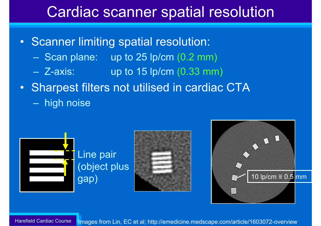
Cardiac scanner spatial resolution
• Scanner limiting spatial resolution: – Scan plane: up to 25 lp/cm (0.2 mm)– Z-axis: up to 15 lp/cm (0.33 mm)
• Sharpest filters not utilised in cardiac CTA – high noise
Images from Lin, EC et al; http://emedicine.medscape.com/article/1603072-overview
10 lp/cm ≡ 0.5 mm
Line pair (object plus gap)
Harefield Cardiac Course
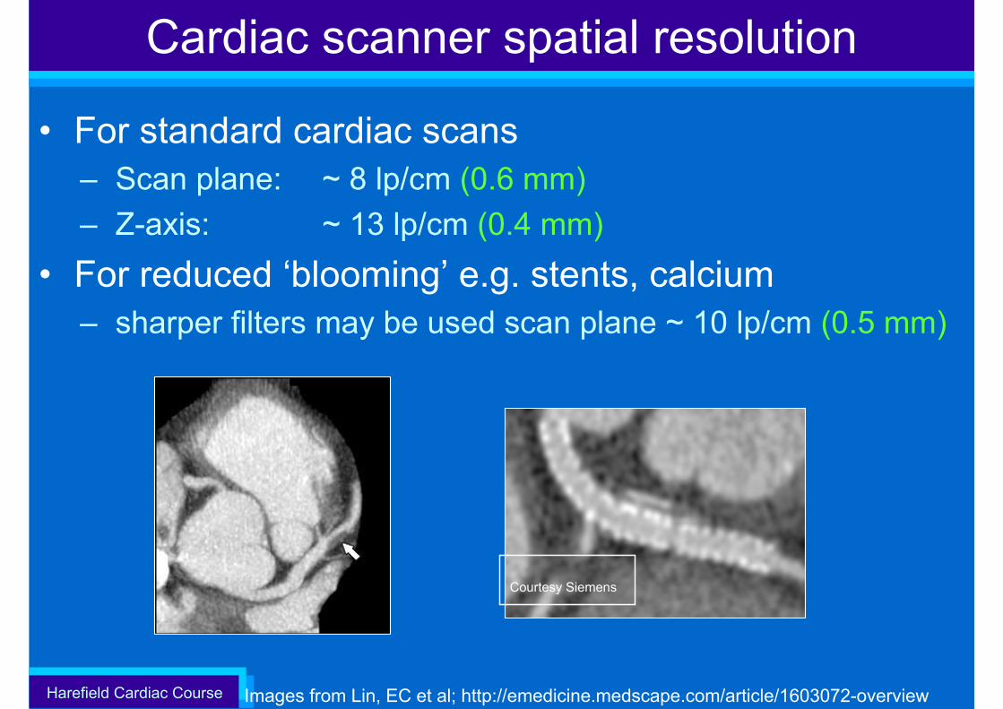
Cardiac scanner spatial resolution
• For standard cardiac scans– Scan plane: ~ 8 lp/cm (0.6 mm) – Z-axis: ~ 13 lp/cm (0.4 mm)
• For reduced ‘blooming’ e.g. stents, calcium– sharper filters may be used scan plane ~ 10 lp/cm (0.5 mm)
Images from Lin, EC et al; http://emedicine.medscape.com/article/1603072-overview
Courtesy Siemens


![Biochemical Aspects of Cardiac Muscle Differentiation · fraction of cardiac muscle tissue slices was determined by incubating slices with [SH]thymidine as described. The slices were](https://img.dokumen.tips/doc/110x75/5f2b711adc56c1182c4ca9a6/biochemical-aspects-of-cardiac-muscle-fraction-of-cardiac-muscle-tissue-slices-was.jpg)