Embed Size (px)
Citation preview
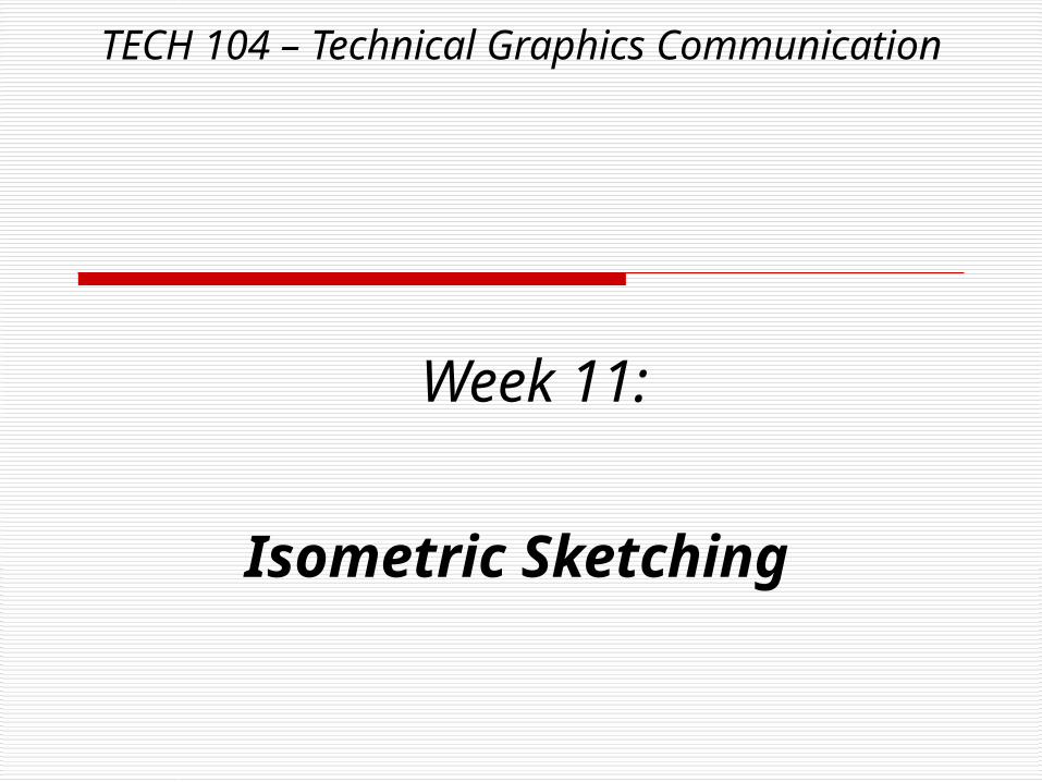
TECH 104 – Technical Graphics Communication
Week 11:
Isometric Sketching
TECH 104 – Technical Graphics Communication
Here’s what we talked about last time…Working Drawings
First,
TECH 104 – Technical Graphics Communication
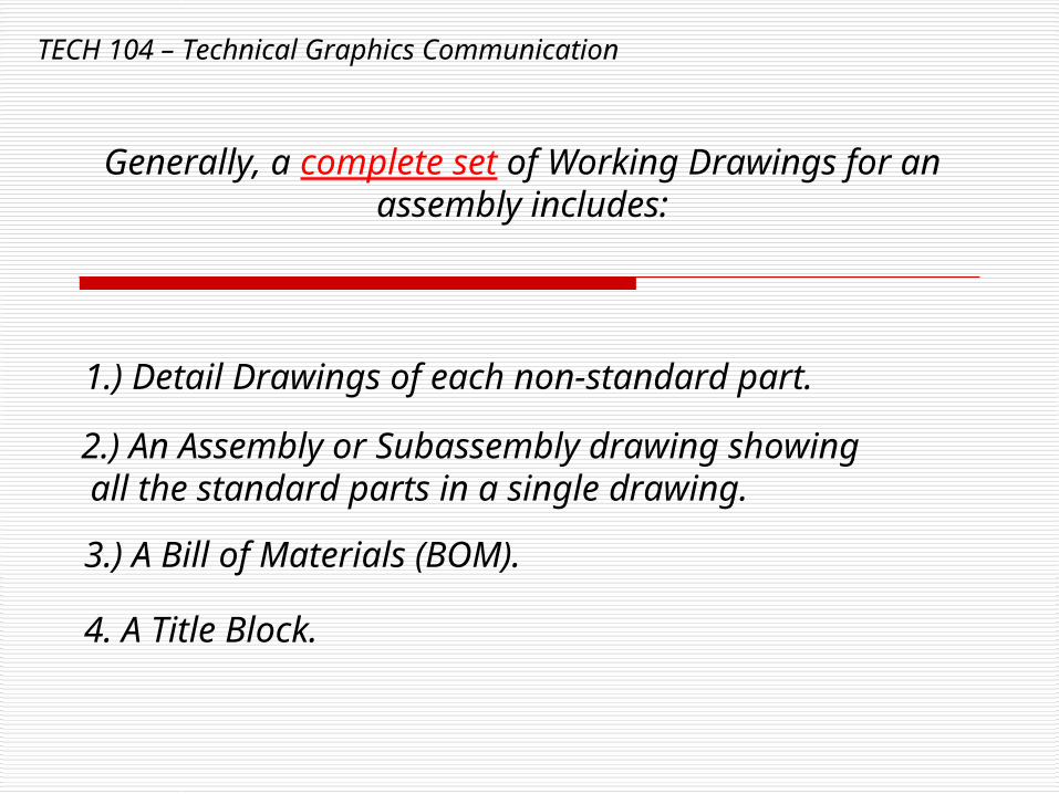
Generally, a complete set of Working Drawings for an assembly includes:
1.) Detail Drawings of each non-standard part.
2.) An Assembly or Subassembly drawing showing all the standard parts in a single drawing.
3.) A Bill of Materials (BOM).
4. A Title Block.
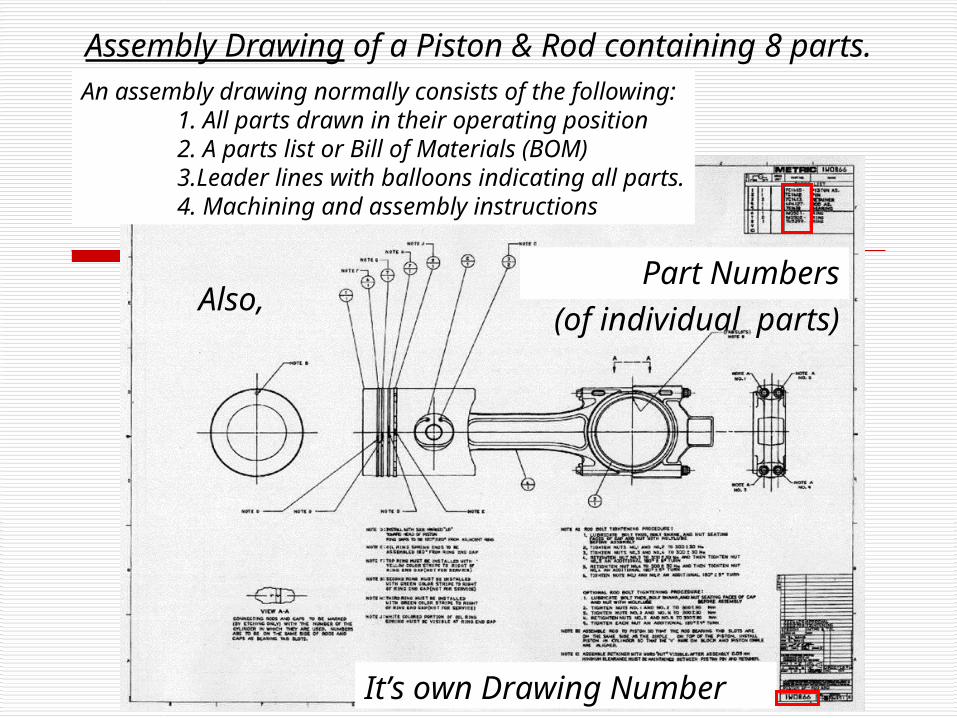
Assembly Drawing of a Piston & Rod containing 8 parts.An assembly drawing normally consists of the following:
1. All parts drawn in their operating position2. A parts list or Bill of Materials (BOM)3.Leader lines with balloons indicating all parts.4. Machining and assembly instructions
It’s own Drawing Number
Part Numbers(of individual
parts)
Also,
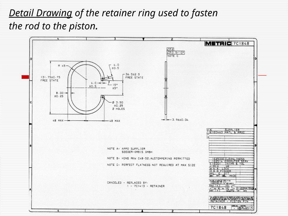
Detail Drawing of the retainer ring used to fasten the rod to the piston.
TECH 104 – Technical Graphics Communication
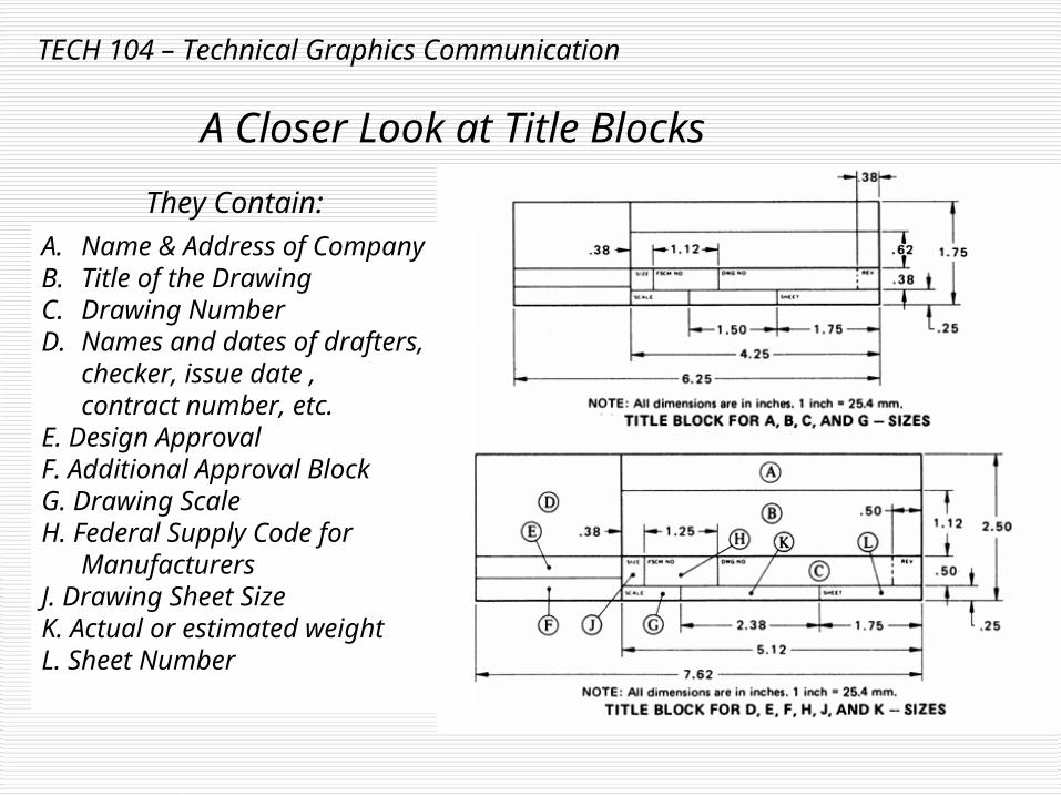
A Closer Look at Title Blocks
A. Name & Address of CompanyB. Title of the DrawingC. Drawing NumberD. Names and dates of drafters,
checker, issue date ,contract number, etc.
E. Design ApprovalF. Additional Approval BlockG. Drawing Scale H. Federal Supply Code for
ManufacturersJ. Drawing Sheet SizeK. Actual or estimated weightL. Sheet Number
They Contain:
TECH 104 – Technical Graphics Communication
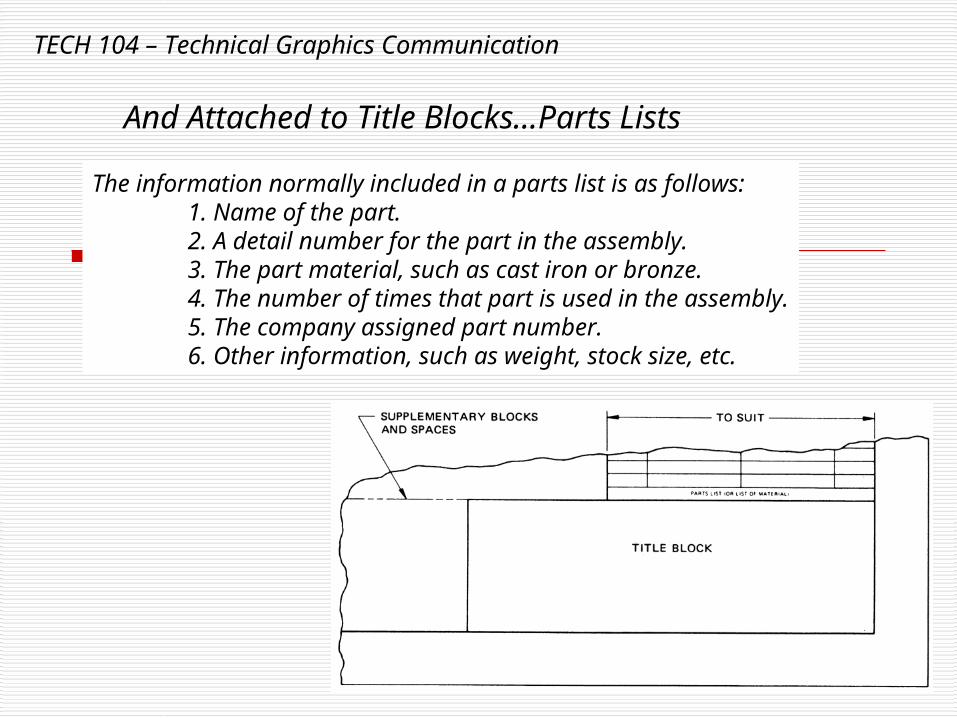
The information normally included in a parts list is as follows:1. Name of the part.2. A detail number for the part in the assembly.3. The part material, such as cast iron or bronze.4. The number of times that part is used in the assembly.5. The company assigned part number.6. Other information, such as weight, stock size, etc.
And Attached to Title Blocks…Parts Lists
TECH 104 – Technical Graphics Communication
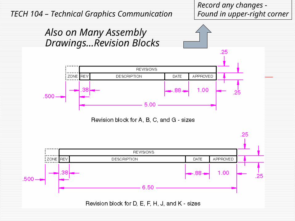
Also on Many Assembly Drawings…Revision Blocks
Record any changes - Found in upper-right corner
TECH 104 – Technical Graphics Communication
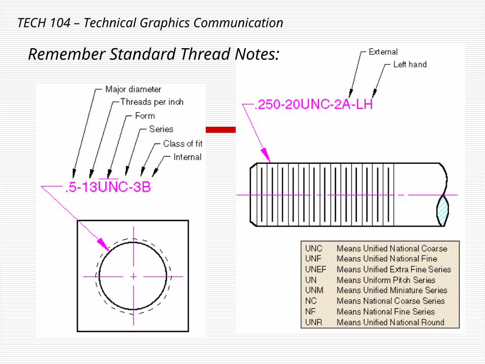
Remember Standard Thread Notes:
TECH 104 – Technical Graphics Communication
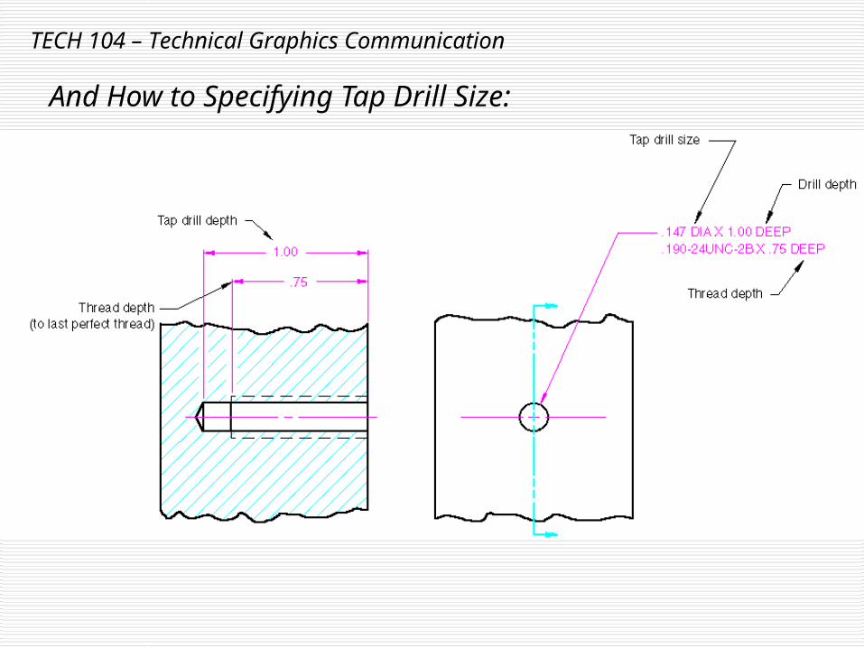
And How to Specifying Tap Drill Size:
TECH 104 – Technical Graphics Communication
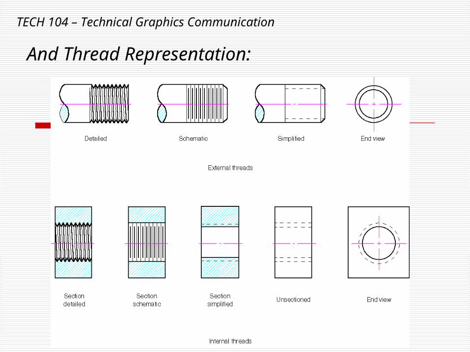
And Thread Representation:
TECH 104 – Technical Graphics Communication
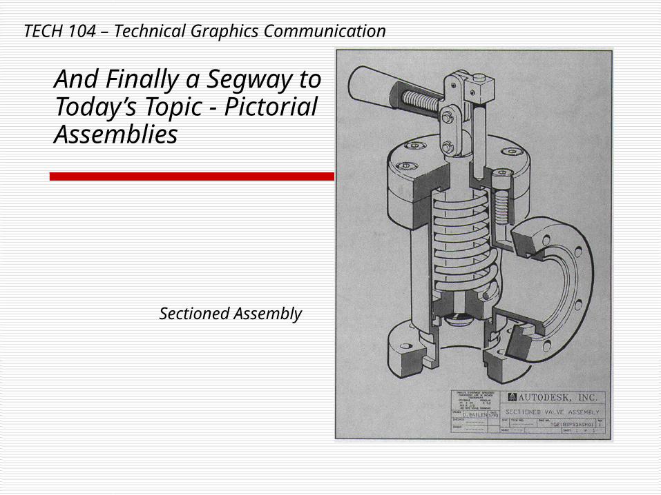
And Finally a Segway to Today’s Topic - Pictorial Assemblies
Sectioned Assembly
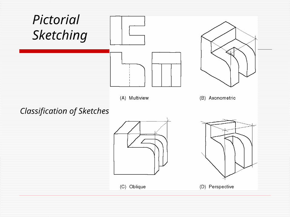
PictorialSketching
Classification of Sketches
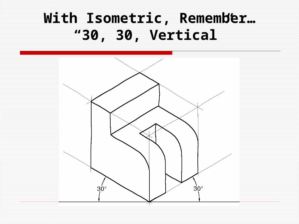
With Isometric, Remember…“30, 30, Vertical”
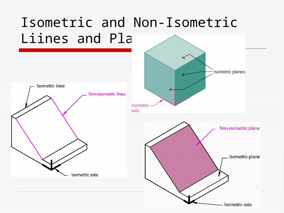
Isometric and Non-Isometric Liines and Planes
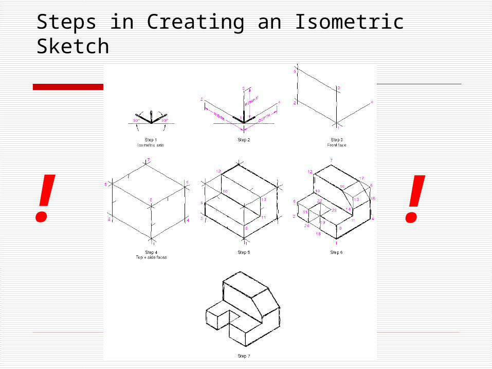
Steps in Creating an Isometric Sketch
! !
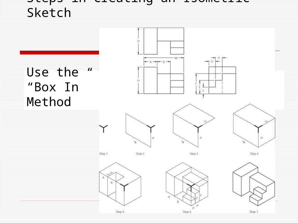
Steps in Creating an Isometric Sketch
Use the“Box In”Method
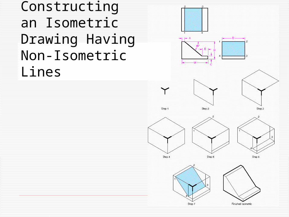
Constructingan Isometric Drawing HavingNon-Isometric Lines

ConstructingAngles in an Isometric Sketch
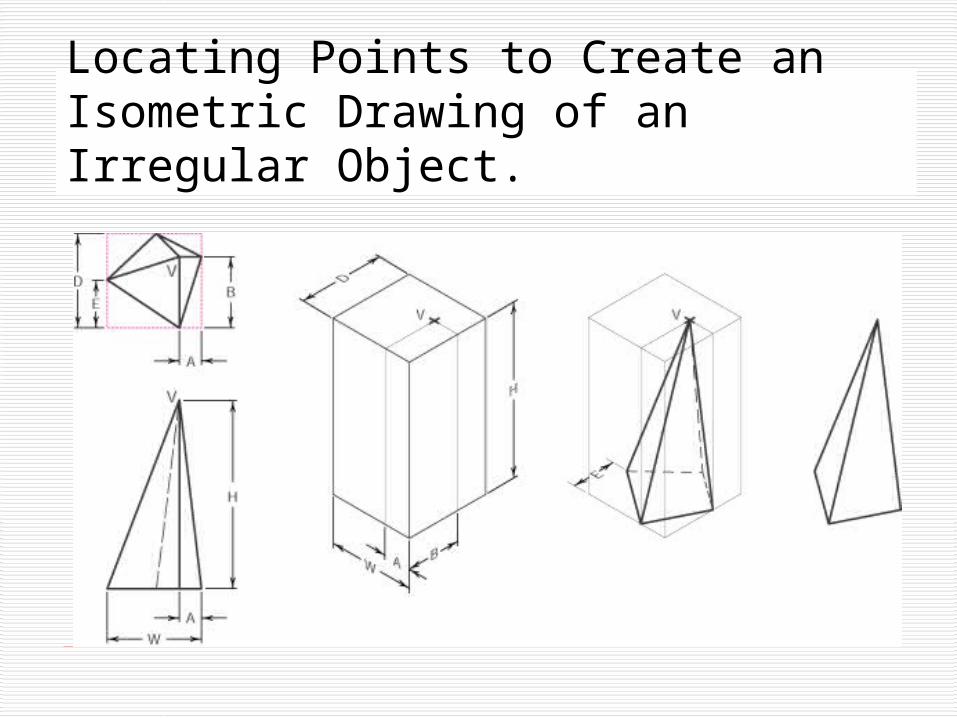
Locating Points to Create an Isometric Drawing of an Irregular Object.
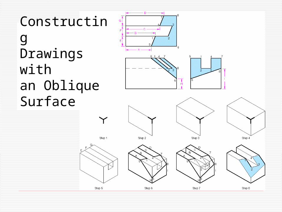
ConstructingDrawings with an ObliqueSurface
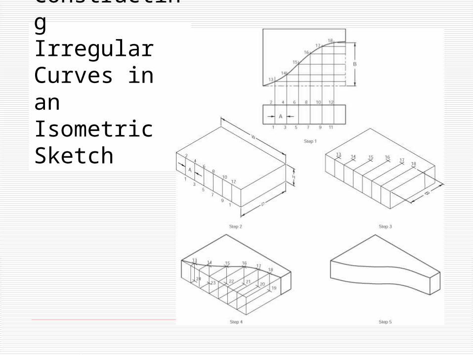
ConstructingIrregular Curves in an Isometric Sketch
TECH 104 – TechnicalGraphics Communication
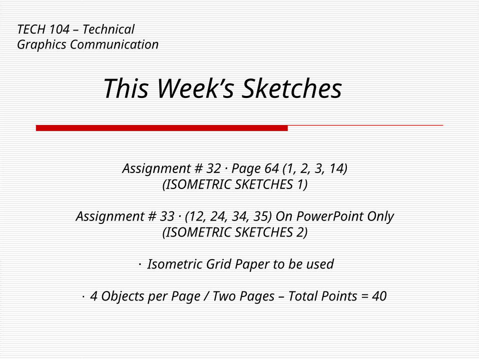
This Week’s Sketches
Assignment # 32 · Page 64 (1, 2, 3, 14)(ISOMETRIC SKETCHES 1)
Assignment # 33 · (12, 24, 34, 35) On PowerPoint Only(ISOMETRIC SKETCHES 2)
∙ Isometric Grid Paper to be used
∙ 4 Objects per Page / Two Pages – Total Points = 40
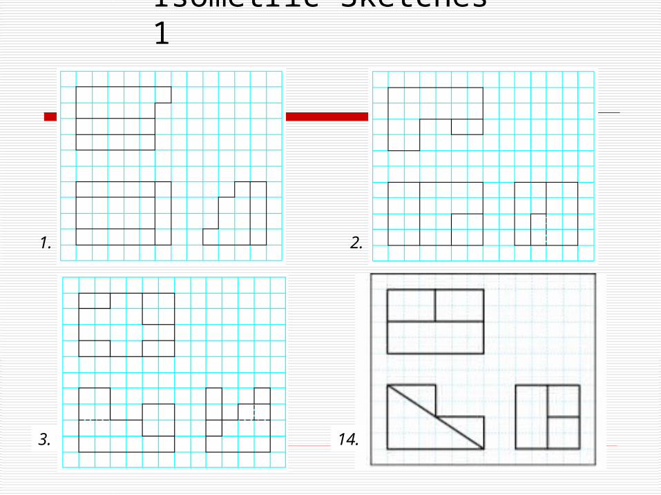
Isometric Sketches 1
1. 2.
3. 14.
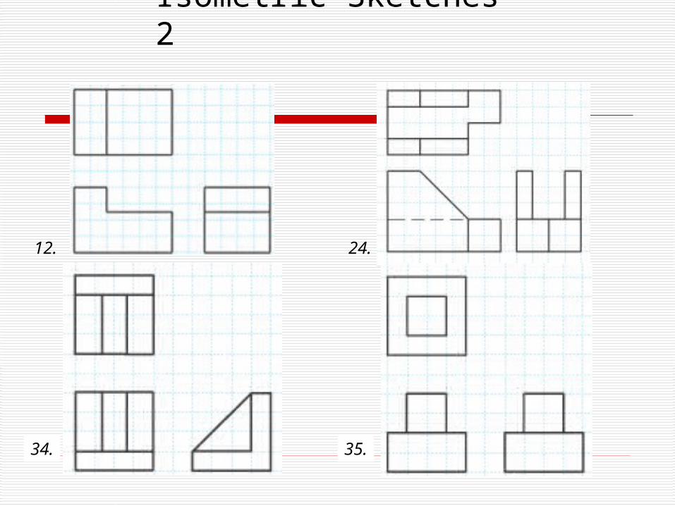
Isometric Sketches 2
12. 24.
34. 35.
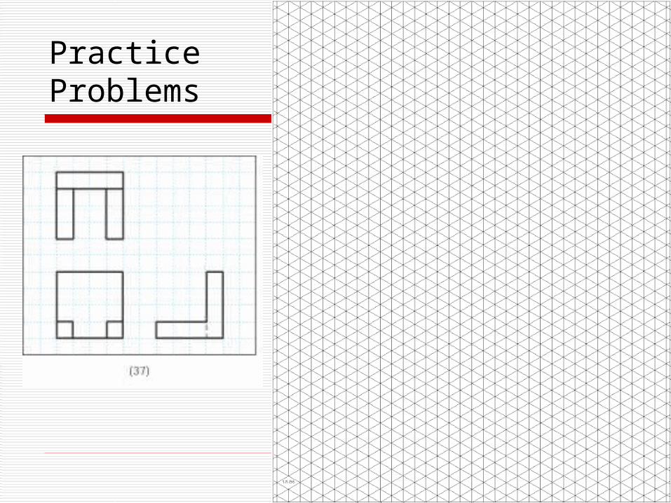
PracticeProblems
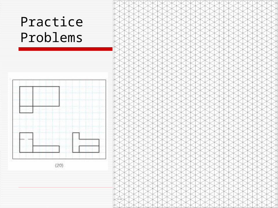
PracticeProblems
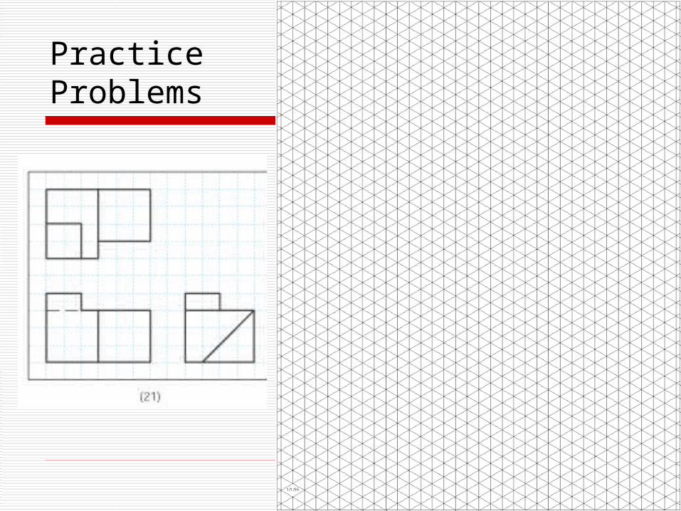
PracticeProblems

PracticeProblems
TECH 104 – Technical Graphics Communication
Week 12:
Isometric Sketching (Continued)