Embed Size (px)
DESCRIPTION
Â
Citation preview

ptg6519239

ptg6519239
in 10 Minutes
GoogleSketchUp 8
SamsTeachYourself
Steven Holzner
800 East 96th Street, Indianapolis, Indiana 46240

ptg6519239
Sams Teach Yourself Google SketchUp 8 in 10 MinutesCopyright © 2011 by Pearson Education, Inc.
All rights reserved. No part of this book shall be reproduced,stored in a retrieval system, or transmitted by any means, elec-tronic, mechanical, photocopying, recording, or otherwise, withoutwritten permission from the publisher. No patent liability isassumed with respect to the use of the information containedherein. Although every precaution has been taken in the prepara-tion of this book, the publisher and author assume no responsibil-ity for errors or omissions. Nor is any liability assumed for dam-ages resulting from the use of the information contained herein.
ISBN-13: 978-0-672-33547-1ISBN-10: 0-672-33547-6
Library of Congress Cataloging-in-Publication Data:
Holzner, Steven.
Sams teach yourself Google SketchUp 8 in 10 minutes / StevenHolzner.
p. cm.
ISBN-13: 978-0-672-33547-1
ISBN-10: 0-672-33547-6
1. Computer graphics. 2. SketchUp. 3. Three-dimensional dis-play systems. 4. Engineering graphics. I. Title.
T385.H6774 2011
006.6’93—dc22
2010049018
Printed in the United States of America
First Printing January 2011
TrademarksAll terms mentioned in this book that are known to be trademarksor service marks have been appropriately capitalized. Pearsoncannot attest to the accuracy of this information. Use of a term inthis book should not be regarded as affecting the validity of anytrademark or service mark.
Warning and DisclaimerEvery effort has been made to make this book as complete andas accurate as possible, but no warranty or fitness is implied. Theinformation provided is on an “as is” basis. The author and thepublisher shall have neither liability nor responsibility to any per-son or entity with respect to any loss or damages arising from theinformation contained in this book.
Bulk SalesPearson offers excellent discounts on this book when ordered inquantity for bulk purchases or special sales. For more informa-tion, please contact
U.S. Corporate and Government [email protected]
For sales outside of the U.S., please contact
International [email protected]
Editor-in-ChiefGreg Wiegand
AcquisitionsEditorRick Kughen
DevelopmentEditorMark Reddin
ManagingEditorSandraSchroeder
SeniorProject EditorTonya Simpson
Copy EditorBarbara Hacha
IndexerTim Wright
Technical EditorTodd Meister
PublishingCoordinatorCindy Teeters
Book DesignerAnne Jones
CompositorMark Shirar
ptg6519239
Table of Contents
Introduction 1
1 Welcome to SketchUp 5Getting Started with SketchUp ..................................................5
Drawing Lines. ........................................................................7
Drawing Simple Figures . ..........................................................7
Pushing (or Pulling) for 3D. ......................................................9
Panning and Orbiting . ............................................................10
Rotating and Moving . ............................................................15
Painting . ..............................................................................17
Using the Component Libraries ..............................................18
Zooming. ..............................................................................19
Creating Guides and Dimension Indicators ..............................22
Lots of Cool Stuff Coming Up ................................................23
2 Up and Running with SketchUp 29What SketchUp Is All About ....................................................29
Getting and Installing SketchUp ..............................................30
Starting SketchUp. ................................................................33
Understanding the Parts of SketchUp......................................36
Using the Orbit Tool . ............................................................37
Using the Pan Tool . ..............................................................39
Using the Zoom Tool . ............................................................40
Selecting a Work Template ....................................................42
Understanding SketchUp Axes ................................................44
Understanding Edges and Surfaces ........................................45
Drawing Edges . ....................................................................48
Inferring Edges . ....................................................................50
3 Drawing Shapes: Lines, Rectangles,Polygons, and Circles 55Getting Started......................................................................55
Drawing Lines........................................................................56
Drawing Multiline Shapes ......................................................57
ptg6519239
Drawing Measured Lines ........................................................59
Drawing Rectangles. ..............................................................60
Drawing Circles. ....................................................................62
Drawing Polygons . ................................................................65
Setting the Number of Sides of Circles or Polygons..................67
Orienting Shapes . ................................................................69
Getting Information About Shapes ..........................................70
Saving Your Work . ................................................................72
4 Drawing Shapes: Arcs, Freehand, Text, and 3D Text 73Arcs, Freehand, and Text ........................................................73
Drawing Arcs . ......................................................................73
Drawing Measured Arcs..........................................................75
Drawing Arcs Tangent to Corners ............................................76
Drawing Multiple Tangent Arcs ................................................79
Setting the Number of Arc Segments ......................................80
Drawing Freehand . ................................................................82
Drawing Surfaces Freehand ....................................................83
Drawing Text . ........................................................................84
Annotating Objects with Text ..................................................86
Setting Text Properties ..........................................................88
Drawing 3D Text . ..................................................................91
5 Going 3D 95Getting Started......................................................................95
Pulling Objects into 3D ..........................................................96
Pushing Objects into 3D ........................................................98
Using Measured Push/Pull ..................................................100
Inferring Push/Pull ..............................................................101
Cutting Openings ................................................................103
Erasing Edges with the Eraser Tool........................................106
Selecting Edges and Surfaces with the Select Tool ................109
Copying Objects ..................................................................110
Moving Edges and Surfaces with the Move Tool ....................112
Drawing 3D by Subtracting Elements ....................................115
ptg6519239
6 Creating Components and Groups 119Getting Started....................................................................119
Using Sticky Geometry ........................................................120
Creating a Group ................................................................121
Creating Components ..........................................................125
Editing Components ............................................................127
Understanding the Difference Between Groups and Components......................................................129
Exploding a Component........................................................132
Managing Components ........................................................133
Using the Component Sampler ............................................135
Using the 3D Warehouse......................................................136
7 Painting Your Objects 141Painting ..............................................................................141
Using the Paint Tool ............................................................143
Selecting Materials ..............................................................145
Eliminating Automatic Shading..............................................146
Drawing in Solid Color ..........................................................148
Painting Multiple Surfaces at Once........................................149
Examining All Materials in Your Model ..................................151
Creating Materials ..............................................................152
Editing Materials..................................................................154
Replacing All of a Material in a Drawing ................................156
Sampling Existing Materials..................................................157
Undoing Changes and Canceling Operations ..........................160
8 Using the Rotate, Scale, and Follow-Me Tools 161Using Some New Tools ........................................................161
Rotating Objects . ................................................................161
Rotating Parts of Objects. ....................................................164
Locking the Rotate Tool’s Orientation ....................................168
Scaling 2D Objects . ............................................................171
Scaling 3D Objects . ............................................................172
ptg6519239
Tapering Objects in 3D ........................................................175
Scaling from the Center of Objects........................................177
Setting Exact Scale . ............................................................178
Using the Follow-Me Tool ......................................................179
9 X-Raying Objects, Creating Guides and Offsets 183Getting Started....................................................................183
X-Raying Objects ..................................................................184
Offsetting Edges with the Offset Tool ....................................186
Selecting Edges to Offset ....................................................189
Creating Exact Offsets..........................................................192
Repeating Offsets on Other Surfaces ....................................194
Measuring Distances with the Tape Measure ........................195
Creating Guides with the Tape Measure Tool..........................198
Drawing Guides at Specific Offsets ......................................200
Deleting Guides ..................................................................204
10 Dimensioning, Drawing Angles,and Getting Cross Sections of Models 205Dimensioning Distances ......................................................206
Dimensioning Arcs . ............................................................208
Freezing Dimensions . ..........................................................209
Configuring Dimensioning Labels ..........................................211
Measuring Angles . ..............................................................214
Creating Guides at Specific Angles........................................217
Creating Cutaway Views of Your Model ..................................220
Reversing the Direction of a Section Cut ..............................222
Index 225

ptg6519239
About the Author
Steven Holzner is the award-winning author of more than 100 books,specializing in online topics such as Google Buzz, Gmail, and more. He’sbeen a contributing editor of PC Magazine and has specialized in onlinecomputing for many years. His books have sold more than 2.5 millioncopies and have been translated into 18 languages. Steve graduated fromMIT and earned his PhD at Cornell. He’s been a very popular member ofthe faculty at both MIT and Cornell, teaching thousands of students overthe years. He also runs his own software company and teaches weeklongclasses to corporate programmers around the country.
Dedication
To Nancy, of course.
Acknowledgements
The book you hold in your hands is the product of the work of many peo-ple. I would especially like to thank Rick Kughen, Mark Reddin, ToddMeister, Tonya Simpson, and Barbara Hacha.
Wow! eBook <WoweBook.Com>

ptg6519239
We Want to Hear from You!
As the reader of this book, you are our most important critic and commen-tator. We value your opinion and want to know what we’re doing right,what we could do better, what areas you’d like to see us publish in, andany other words of wisdom you’re willing to pass our way.
You can email or write me directly to let me know what you did or didn’tlike about this book—as well as what we can do to make our booksstronger.
Please note that I cannot help you with technical problems related tothe topic of this book, and that due to the high volume of mail Ireceive, I might not be able to reply to every message.
When you write, please be sure to include this book’s title and author aswell as your name and phone or email address. I will carefully reviewyour comments and share them with the author and editors who workedon the book.
E-mail: [email protected]
Mail: Greg WiegandEditor-in-ChiefSams Publishing800 East 96th StreetIndianapolis, IN 46240 USA
Reader Services
Visit our website and register this book at informit.com/register for conve-nient access to any updates, downloads, or errata that might be availablefor this book.
Wow! eBook <WoweBook.Com>
ptg6519239
Introduction
Welcome to SketchUp! This book is all about Google’s fantastically popu-lar 3D modeling program, ready for you to create 3D drawings with.
SketchUp is ultrapowerful, and lets you draw models with ease. Need todraw a new engine? SketchUp can do it. Need to lay out your back yardplantings? SketchUp can help. Want to plan a new office, positioningchairs, desks, and workstations as needed? SketchUp is for you.
SketchUp’s forte is 3D modeling—creating drawings of 3D objects. Thereare plenty of 2D drawing programs out there but very few of SketchUp’scaliber and ease of use for 3D.
Want to become a SketchUp-meister? Stay tuned, you’ve come to theright book.
NOTE: What’s New In Google SketchUp 8
SketchUp 8 offers a variety of new features not found in SketchUp7. For a list of what’s new in SketchUp, see http://sketchup.google.com/product/newin8.html
What’s in This BookYou’re going to get a guided tour of SketchUp in this book. SketchUp istoo large a program to cover in complete detail in a book this size, butyou’re going to get a real working knowledge of SketchUp, suitable forcreating just about any drawing you want.
SketchUp offers you a super-powerful set of tools to work with, and thisbook is about those tools. We’ll see how to draw basic figures using toolssuch as
. The Rectangle tool
. The Circle tool
Wow! eBook <WoweBook.Com>
ptg6519239
2 Sams Teach Yourself Google SketchUp 8 in 10 Minutes
. The Polygon tool
. The Arc tool
as well as how to draw freehand.
We’ll see how to use tools to convert from 2D to 3D—tools like
. The Push/Pull tool
. The Move tool
. The Rotate tool
After going 3D, we’ll make use of the tools SketchUp offers for viewing3D objects, such as
. The Orbit tool
. The Pan tool
. The Zoom tool
Having mastered 3D concepts and after we’re used to creating 3D objects,we’ll see how to measure lengths and angles, as well as construct con-struction guides with tools such as
. The Tape Measure tool
. The Dimensioning tool
. The Protractor tool
Then we’ll start getting into some tools specific to SketchUp, giving youmore 3D power:
. The Offset tool
. The Follow-Me tool
. The Section Pane tool
And more!
These tools are particular to SketchUp, and only SketchUp offers theirkind of power. The Offset tool lets you draw copies of edges at offsets
Wow! eBook <WoweBook.Com>
ptg6519239
3Introduction
from the original in case you want to repeat that surface (as when, forexample, you’re drawing an ornate window frame and want to copy acurved edge to create a whole window frame). The Follow-Me tool is anamazing one—it lets you specify a path and a shape or action, then pullsthat shape or action around your path, giving you a 3D result (so, forexample, if you bevel one side of a chair seat and want to bevel the otherthree sides similarly, you can use the Follow-Me tool). And the SectionPane tool lets you draw cross-sections through any surface in your model.
And there are yet more tools coming up, such as the Scale tool, whichenlarges or reduces models just by dragging the mouse, the TextAnnotation tool, which lets you add notes to your models, the 3D Texttool, which lets you draw 3D text, and more.
All of which is to say: there’s a lot coming up on your guided tour.
Conventions Used in This BookWhenever you need to click a particular button or link in SketchUp, you’llfind the label or name for that item bolded in the text, such as “click theLine tool.” In addition to the text and figures in this book, you alsoencounter some special boxes labelled Tip, Note, or Caution.
TIP: Tips offer helpful shortcuts or easier ways to do something.
NOTE: Notes are extra bits of information related to the text thatmight help you expand your knowledge or understanding.
CAUTION: Cautions are warnings or other important information youneed to know about consequences of using a feature or executinga task.
Wow! eBook <WoweBook.Com>

ptg6519239
4 Sams Teach Yourself Google SketchUp 8 in 10 Minutes
What You’ll NeedAll you’ll need to use this book is Google SketchUp itself.
SketchUp comes in two versions—free and paid. The paid version is the“professional” version, but the free version is also immensely powerful.We’ll be using the free version here. All you have to do is to download andinstall it, following the directions at the beginning of Lesson 2.
That’s it. Everything you need for this book comes in SketchUp itself.There’s nothing else needed. After you’ve installed the free version, you’reready to roll.
Wow! eBook <WoweBook.Com>

ptg6519239
LESSON 1
Welcome to SketchUp
Welcome to Google SketchUp—the most powerful 3D graphics programyou can get for free (and it even comes in a paid version as well for extrapower).
Getting Started with SketchUpThere’s a huge amount of material to cover when talking about SketchUp,so we’re going to spend this first lesson getting a short overview of what’spossible. In the book as a whole, we’re going to get a real working knowl-edge of SketchUp—enough to get you building and working with complexmodels.
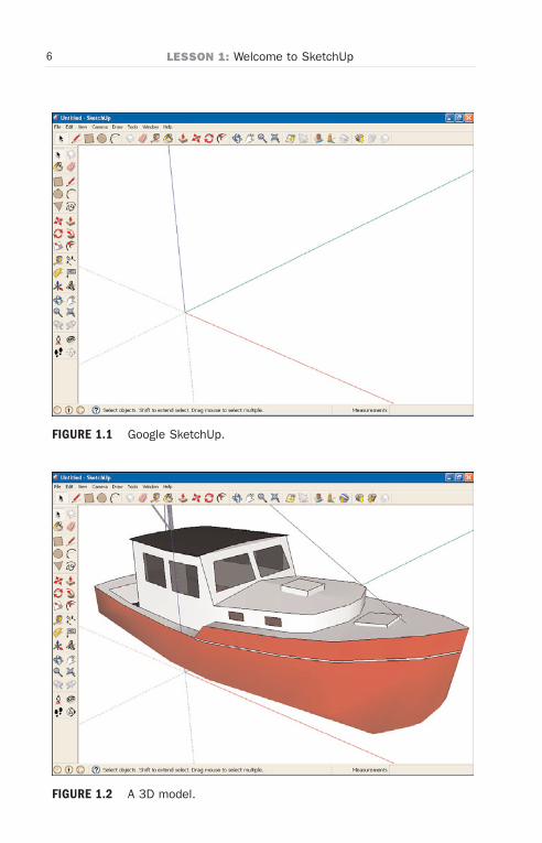
Let’s start by taking a look at SketchUp itself, which appears in Figure 1.1.
As you can see in Figure 1.1, Google SketchUp gives you a set of threeaxes, giving your drawing a 3D feel from the start. That’s appropriatebecause SketchUp is a 3D program; that is its main claim to fame.
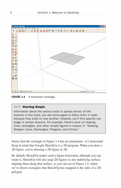
It’s simple to create 3D objects in SketchUp, and you can do so in a vari-ety of ways, as we’re going to see. The most amazing 3D models are pos-sible in SketchUp. Take a look at Figure 1.2, for example.
You draw models like the one in the figure using tools from the toolbars.By selecting individual tools such as the Line tool, the Circle tool, thePolygon tool, and so on, you create the shapes step by step that composeyour desired model.
Let’s start with an overview of SketchUp in this lesson; then we’ll installand start working with SketchUp in the next lesson.
Wow! eBook <WoweBook.Com>
ptg6519239
6 LESSON 1: Welcome to SketchUp
FIGURE 1.2 A 3D model.
FIGURE 1.1 Google SketchUp.
Wow! eBook <WoweBook.Com>

ptg6519239
7Drawing Lines
FIGURE 1.3 Drawing lines.
Drawing LinesWhen you first start SketchUp, the Line tool is selected by default. And, asyou might expect, you can draw lines with this tool—see Figure 1.3.
Drawing lines is one of the simplest of figures you can make inSketchUp—lines are one-dimensional, so they don’t exhibit any of thehelpful behavior SketchUp adds to other figures, such as snapping to axes,being colored automatically, and more, as we’re about to see.
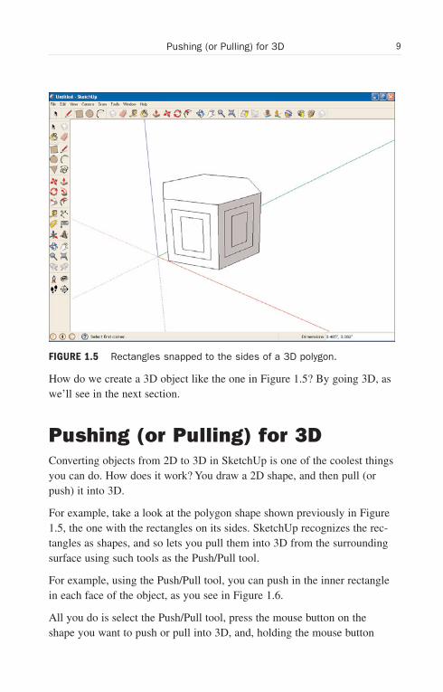
Drawing Simple FiguresUsing tools such as the Rectangle tool, you can draw 2D shapes, like therectangle you see in Figure 1.4.
Besides rectangles, you can draw circles, polygons, and arcs using the cor-responding tools.
Wow! eBook <WoweBook.Com>
ptg6519239
8 LESSON 1: Welcome to SketchUp
FIGURE 1.4 A horizontal rectangle.
NOTE: Starting Simple
Information about the various tools is spread across all thelessons in this book; you are encouraged to follow them in orderbecause they build on one another. However, you’ll find specific cov-erage in certain lessons. For example, there’s more on drawinglines, rectangles, and other simple figures in Lesson 3, “DrawingShapes: Lines, Rectangles, Polygons, and Circles.”
Notice that the rectangle in Figure 1.4 has an orientation—it’s horizontal.Keep in mind that Google SketchUp is a 3D program. When you draw a2D figure, you’re drawing a 2D figure in 3D.
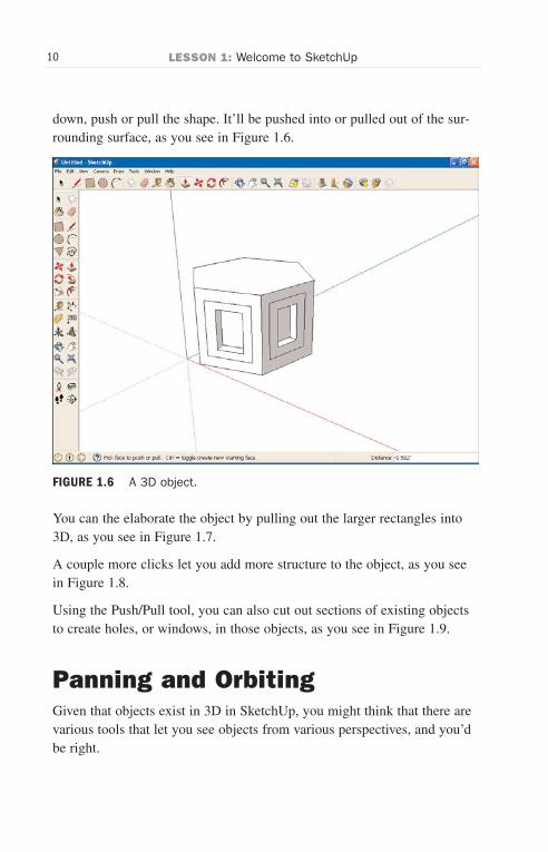
By default, SketchUp makes such a figure horizontal, although you canrotate it. SketchUp will also snap 2D figures to any underlying surface,aligning them along that surface, as you can see in Figure 1.5, wherewe’ve drawn rectangles that SketchUp has snapped to the sides of a 3Dpolygon.
Wow! eBook <WoweBook.Com>
ptg6519239
9Pushing (or Pulling) for 3D
How do we create a 3D object like the one in Figure 1.5? By going 3D, aswe’ll see in the next section.
Pushing (or Pulling) for 3DConverting objects from 2D to 3D in SketchUp is one of the coolest thingsyou can do. How does it work? You draw a 2D shape, and then pull (orpush) it into 3D.
For example, take a look at the polygon shape shown previously in Figure1.5, the one with the rectangles on its sides. SketchUp recognizes the rec-tangles as shapes, and so lets you pull them into 3D from the surroundingsurface using such tools as the Push/Pull tool.
For example, using the Push/Pull tool, you can push in the inner rectanglein each face of the object, as you see in Figure 1.6.
All you do is select the Push/Pull tool, press the mouse button on theshape you want to push or pull into 3D, and, holding the mouse button
FIGURE 1.5 Rectangles snapped to the sides of a 3D polygon.
Wow! eBook <WoweBook.Com>
ptg6519239
10 LESSON 1: Welcome to SketchUp
FIGURE 1.6 A 3D object.
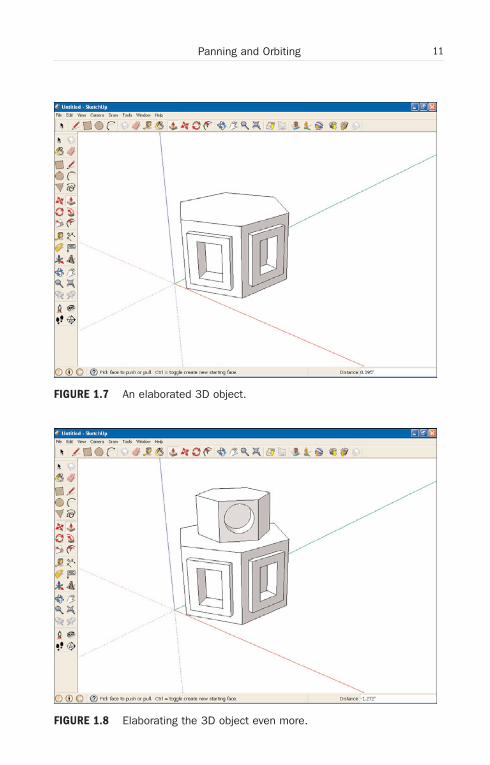
You can the elaborate the object by pulling out the larger rectangles into3D, as you see in Figure 1.7.
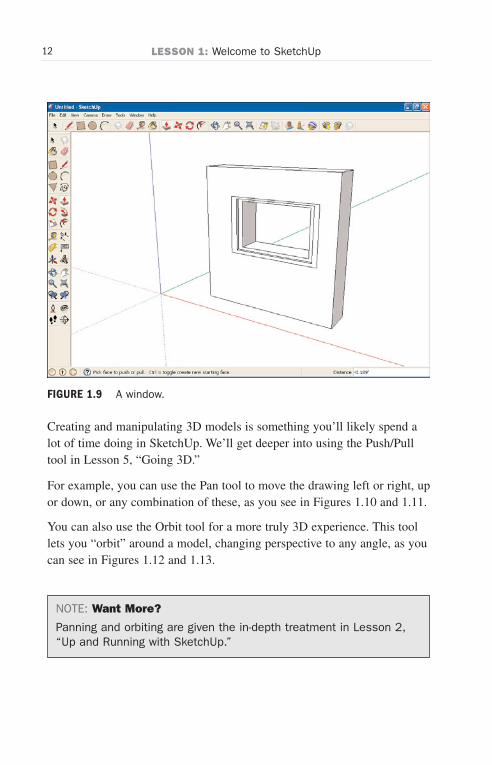
A couple more clicks let you add more structure to the object, as you seein Figure 1.8.
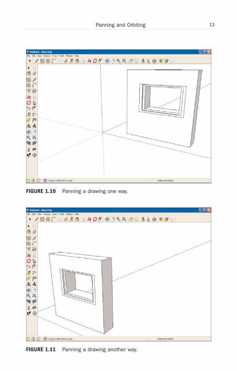
Using the Push/Pull tool, you can also cut out sections of existing objectsto create holes, or windows, in those objects, as you see in Figure 1.9.
Panning and OrbitingGiven that objects exist in 3D in SketchUp, you might think that there arevarious tools that let you see objects from various perspectives, and you’dbe right.
down, push or pull the shape. It’ll be pushed into or pulled out of the sur-rounding surface, as you see in Figure 1.6.
Wow! eBook <WoweBook.Com>
ptg6519239
11Panning and Orbiting
FIGURE 1.7 An elaborated 3D object.
FIGURE 1.8 Elaborating the 3D object even more.
Wow! eBook <WoweBook.Com>
ptg6519239
12 LESSON 1: Welcome to SketchUp
FIGURE 1.9 A window.
Creating and manipulating 3D models is something you’ll likely spend alot of time doing in SketchUp. We’ll get deeper into using the Push/Pulltool in Lesson 5, “Going 3D.”
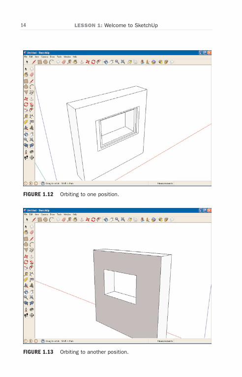
For example, you can use the Pan tool to move the drawing left or right, upor down, or any combination of these, as you see in Figures 1.10 and 1.11.
You can also use the Orbit tool for a more truly 3D experience. This toollets you “orbit” around a model, changing perspective to any angle, as youcan see in Figures 1.12 and 1.13.
NOTE: Want More?
Panning and orbiting are given the in-depth treatment in Lesson 2,“Up and Running with SketchUp.”
Wow! eBook <WoweBook.Com>
ptg6519239
13Panning and Orbiting
FIGURE 1.10 Panning a drawing one way.
FIGURE 1.11 Panning a drawing another way.
Wow! eBook <WoweBook.Com>
ptg6519239
14 LESSON 1: Welcome to SketchUp
FIGURE 1.12 Orbiting to one position.
FIGURE 1.13 Orbiting to another position.
Wow! eBook <WoweBook.Com>

ptg6519239
15Rotating and Moving
You can also move and rotate objects themselves rather than just perspective.
Rotating and MovingAlthough these tools are fairly self-explanatory, they are incredibly useful,as you might imagine. Note that while the Orbit tool lets you orbit aroundan object, the Rotate tool lets you rotate the object itself.
Take a look at Figure 1.14, showing a piano and a drum set.
Using the Rotate tool, you can rotate objects, as shown in Figure 1.15.
And using the Move tool, you can move objects around your drawing, asshown in Figure 1.16. Notice that the piano has been rotated from its posi-tion shown in Figure 1.15.
There is an infinite number of reasons you might want to rotate or moveobjects, so for more on these tools check out Lesson 8, “Using the Rotate,Scale, and Follow-Me Tools,” and Lesson 5, “Going 3D,” respectively.
FIGURE 1.14 A piano and a drum set.
Wow! eBook <WoweBook.Com>

ptg6519239
16 LESSON 1: Welcome to SketchUp
FIGURE 1.15 Rotating an object.
FIGURE 1.16 Moving an object.
Wow! eBook <WoweBook.Com>
ptg6519239
17Painting
PaintingGoogle SketchUp lets you paint the objects you create. You can paint themwith solid colors, and you can select from dozens of textures as well.
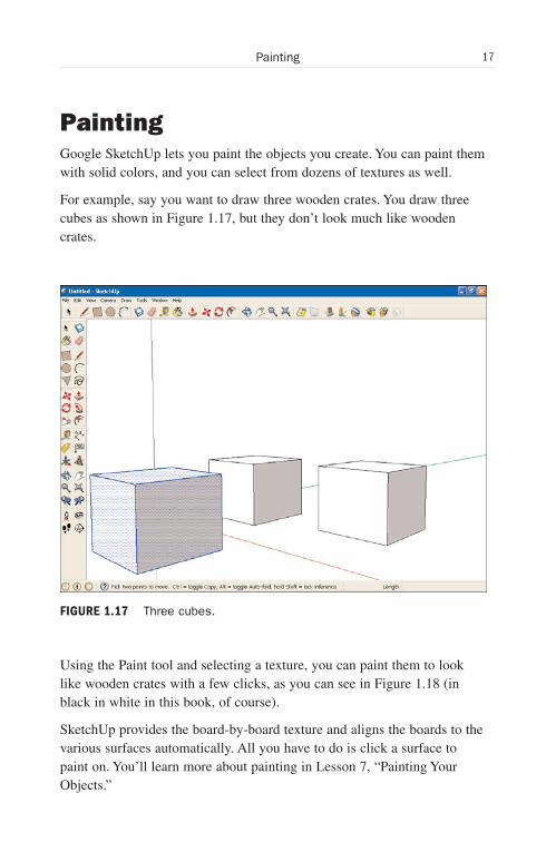
For example, say you want to draw three wooden crates. You draw threecubes as shown in Figure 1.17, but they don’t look much like woodencrates.
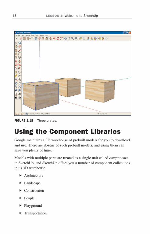
Using the Paint tool and selecting a texture, you can paint them to looklike wooden crates with a few clicks, as you can see in Figure 1.18 (inblack in white in this book, of course).
SketchUp provides the board-by-board texture and aligns the boards to thevarious surfaces automatically. All you have to do is click a surface topaint on. You’ll learn more about painting in Lesson 7, “Painting YourObjects.”
FIGURE 1.17 Three cubes.
Wow! eBook <WoweBook.Com>
ptg6519239
18 LESSON 1: Welcome to SketchUp
FIGURE 1.18 Three crates.
Using the Component LibrariesGoogle maintains a 3D warehouse of prebuilt models for you to downloadand use. There are dozens of such prebuilt models, and using them cansave you plenty of time.
Models with multiple parts are treated as a single unit called componentsin SketchUp, and SketchUp offers you a number of component collectionsin its 3D warehouse:
. Architecture
. Landscape
. Construction
. People
. Playground
. Transportation
Wow! eBook <WoweBook.Com>
ptg6519239
19Zooming
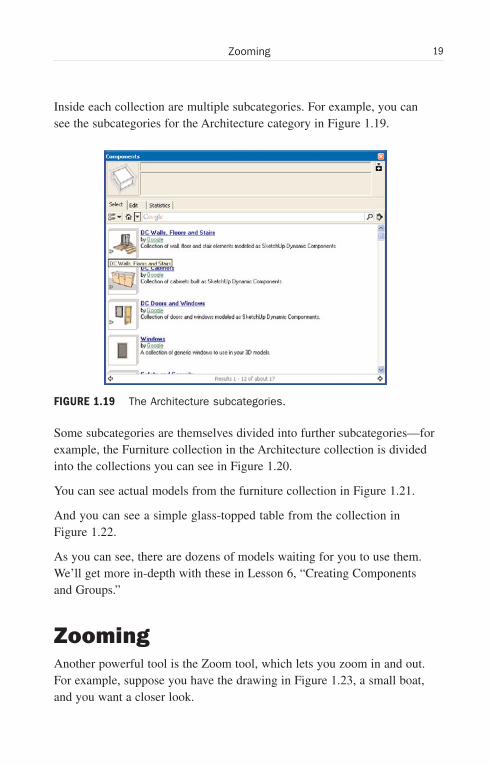
Inside each collection are multiple subcategories. For example, you cansee the subcategories for the Architecture category in Figure 1.19.
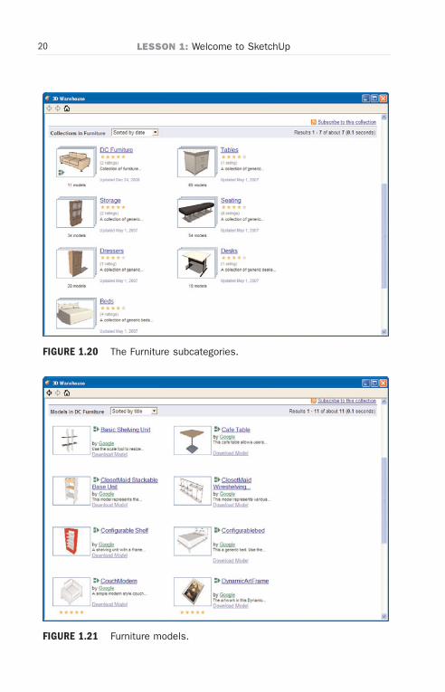
Some subcategories are themselves divided into further subcategories—forexample, the Furniture collection in the Architecture collection is dividedinto the collections you can see in Figure 1.20.
You can see actual models from the furniture collection in Figure 1.21.
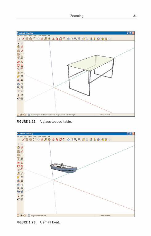
And you can see a simple glass-topped table from the collection inFigure 1.22.
As you can see, there are dozens of models waiting for you to use them.We’ll get more in-depth with these in Lesson 6, “Creating Componentsand Groups.”
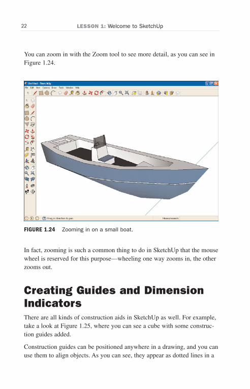
ZoomingAnother powerful tool is the Zoom tool, which lets you zoom in and out.For example, suppose you have the drawing in Figure 1.23, a small boat,and you want a closer look.
FIGURE 1.19 The Architecture subcategories.
Wow! eBook <WoweBook.Com>
ptg6519239
20 LESSON 1: Welcome to SketchUp
FIGURE 1.20 The Furniture subcategories.
FIGURE 1.21 Furniture models.
Wow! eBook <WoweBook.Com>
ptg6519239
21Zooming
FIGURE 1.22 A glass-topped table.
FIGURE 1.23 A small boat.
Wow! eBook <WoweBook.Com>
ptg6519239
22 LESSON 1: Welcome to SketchUp
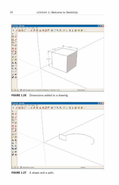
You can zoom in with the Zoom tool to see more detail, as you can see inFigure 1.24.
In fact, zooming is such a common thing to do in SketchUp that the mousewheel is reserved for this purpose—wheeling one way zooms in, the otherzooms out.
Creating Guides and DimensionIndicatorsThere are all kinds of construction aids in SketchUp as well. For example,take a look at Figure 1.25, where you can see a cube with some construc-tion guides added.
Construction guides can be positioned anywhere in a drawing, and you canuse them to align objects. As you can see, they appear as dotted lines in a
FIGURE 1.24 Zooming in on a small boat.
Wow! eBook <WoweBook.Com>

ptg6519239
23Lots of Cool Stuff Coming Up
FIGURE 1.25 A cube with construction guides.
You can also add dimensioning indicators to a drawing, as you see inFigure 1.26.
Those dimensions will change as you resize an object. Lesson 10,“Dimensioning, Drawing Angles, and Getting Cross Sections of Models”is where you will find more on this topic.
Lots of Cool Stuff Coming UpThere is a lot of cool stuff coming up, such as the Follow-Me tool, whichlets you specify a path and a shape, as you see in Figure 1.27.
With the Follow-Me tool, you can make SketchUp move the shape along thepath you’ve specified, resulting in a new object, as you see in Figure 1.28.
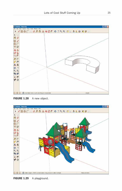
Suppose you had a model of a playground, as shown in Figure 1.29.
drawing, and if you wanted to add another cube lined up with the currentone, you could use those guides to help.
Wow! eBook <WoweBook.Com>
ptg6519239
24 LESSON 1: Welcome to SketchUp
FIGURE 1.26 Dimensions added to a drawing.
FIGURE 1.27 A shape and a path.
Wow! eBook <WoweBook.Com>
ptg6519239
25Lots of Cool Stuff Coming Up
FIGURE 1.28 A new object.
FIGURE 1.29 A playground.
Wow! eBook <WoweBook.Com>
ptg6519239
26 LESSON 1: Welcome to SketchUp
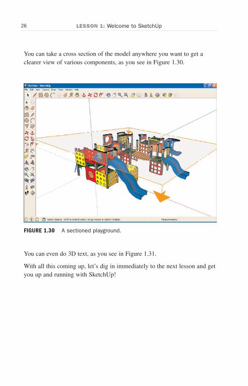
You can take a cross section of the model anywhere you want to get aclearer view of various components, as you see in Figure 1.30.
You can even do 3D text, as you see in Figure 1.31.
With all this coming up, let’s dig in immediately to the next lesson and getyou up and running with SketchUp!
FIGURE 1.30 A sectioned playground.
Wow! eBook <WoweBook.Com>

ptg6519239
27Lots of Cool Stuff Coming Up
FIGURE 1.31 3D text.
Wow! eBook <WoweBook.Com>

ptg6519239
This page intentionally left blank
Wow! eBook <WoweBook.Com>
ptg6519239
LESSON 2
Up and Running withSketchUp
You’re about to start working with an amazing program—GoogleSketchUp.
What SketchUp Is All AboutThe name of the game with Google SketchUp is 3D drawing. Not justdrawing, because there are tons of programs out there to help you withthat, but 3D drawing. In this lesson, you’ll see how easy and quick it is tocreate 3D drawings.
That’s not to say that all of SketchUp is easy. A program this complex hassome sticky points, which we’re going to cover in this book. But Googlehas made 3D drawing just about as simple as it could become and stillretain real power.
SketchUp comes in two versions—SketchUp itself, which is free, andSketchUp Pro, which is not. We’re going to be using SketchUp—the freeversion—in this book, but you should also know SketchUp Pro is availablein case SketchUp doesn’t meet your needs.
TIP: SketchUp Pro
SketchUp Pro is 3D modeling software for professionals. Pro isbilled as being everything that traditional CAD software is, only eas-ier to learn and more intuitive. Pro enables you to import drawings,CAD plans, photos, aerial imagery, and more. It also enables you toexport and share your projects more easily. At $495, however, Prois a significant investment. We recommend that you give the free
Wow! eBook <WoweBook.Com>
ptg6519239
30 LESSON 2: Up and Running with SketchUp
version a try first. It might do everything you need and more.However, if you use SketchUp extensively and need the more pow-erful features offered in the Pro edition, you might consider ponyingup for the upgrade. Go to the following site to compare features inPro with the features found in the free version: http://sketchup.google.com/intl/en/product/whygopro.html
This lesson gets us started with SketchUp. We’ll see where to get it andinstall it. Then we’ll start SketchUp and cover the basic concepts you needto know before using it.
Then we’ll take it out for a spin.
Let’s jump in immediately by installing SketchUp.
Getting and Installing SketchUpYou can download SketchUp for free from its website. Just follow thesedirections:
1. Navigate to the SketchUp site, www.sketchup.com (or http://sketchup.google.com). The SketchUp site appears, as shown inFigure 2.1.
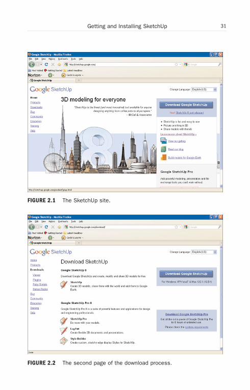
2. Click the Download Google SketchUp button. This causes thepage you see in Figure 2.2 to appear.
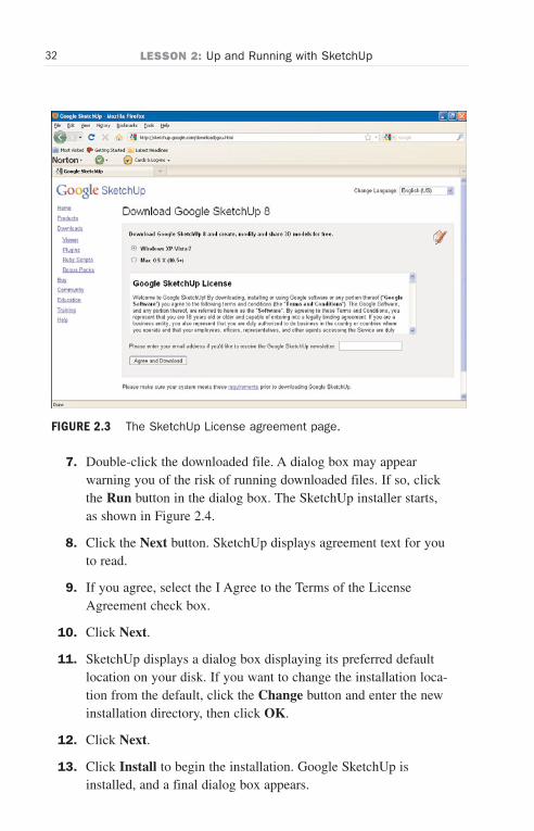
3. Click the Download Google SketchUp button again. This bringsup the license agreement you see in Figure 2.3.
4. Select the option button for your operating system. The choices are
. Windows XP/Vista/7
. Mac OS X (10.5+)
5. Read the terms and click the Agree and Download button.
6. Let your browser download and save the installation file.Depending on your browser, you might have to click a yellow barat top of the browser window and select the Download Filemenu item. If your browser asks you where to save the file, selecta convenient directory, or create a new one named SketchUp.
Wow! eBook <WoweBook.Com>
ptg6519239
31Getting and Installing SketchUp
FIGURE 2.2 The second page of the download process.
FIGURE 2.1 The SketchUp site.
Wow! eBook <WoweBook.Com>
ptg6519239
32 LESSON 2: Up and Running with SketchUp
FIGURE 2.3 The SketchUp License agreement page.
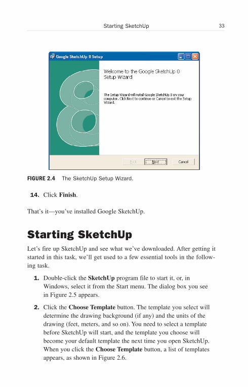
7. Double-click the downloaded file. A dialog box may appearwarning you of the risk of running downloaded files. If so, clickthe Run button in the dialog box. The SketchUp installer starts,as shown in Figure 2.4.
8. Click the Next button. SketchUp displays agreement text for youto read.
9. If you agree, select the I Agree to the Terms of the LicenseAgreement check box.
10. Click Next.
11. SketchUp displays a dialog box displaying its preferred defaultlocation on your disk. If you want to change the installation loca-tion from the default, click the Change button and enter the newinstallation directory, then click OK.
12. Click Next.
13. Click Install to begin the installation. Google SketchUp isinstalled, and a final dialog box appears.
Wow! eBook <WoweBook.Com>
ptg6519239
33Starting SketchUp
FIGURE 2.4 The SketchUp Setup Wizard.
14. Click Finish.
That’s it—you’ve installed Google SketchUp.
Starting SketchUpLet’s fire up SketchUp and see what we’ve downloaded. After getting itstarted in this task, we’ll get used to a few essential tools in the follow-ing task.
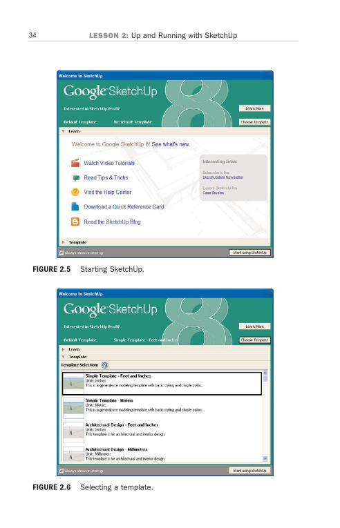
1. Double-click the SketchUp program file to start it, or, inWindows, select it from the Start menu. The dialog box you seein Figure 2.5 appears.
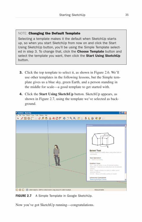
2. Click the Choose Template button. The template you select willdetermine the drawing background (if any) and the units of thedrawing (feet, meters, and so on). You need to select a templatebefore SketchUp will start, and the template you choose willbecome your default template the next time you open SketchUp.When you click the Choose Template button, a list of templatesappears, as shown in Figure 2.6.
Wow! eBook <WoweBook.Com>
ptg6519239
34 LESSON 2: Up and Running with SketchUp
FIGURE 2.5 Starting SketchUp.
FIGURE 2.6 Selecting a template.
Wow! eBook <WoweBook.Com>
ptg6519239
35Starting SketchUp
NOTE: Changing the Default Template
Selecting a template makes it the default when SketchUp startsup, so when you start SketchUp from now on and click the StartUsing SketchUp button, you’ll be using the Simple Template select-ed in step 3. To change that, click the Choose Template button andselect the template you want, then click the Start Using SketchUpbutton.
3. Click the top template to select it, as shown in Figure 2.6. We’lluse other templates in the following lessons, but the Simple tem-plate gives us a blue sky, green Earth, and a person standing inthe middle for scale—a good template to get started with.
4. Click the Start Using SketchUp button. SketchUp appears, asshown in Figure 2.7, using the template we’ve selected as back-ground.
Now you’ve got SketchUp running—congratulations.
FIGURE 2.7 A Simple Template in Google SketchUp.
Wow! eBook <WoweBook.Com>
ptg6519239
36 LESSON 2: Up and Running with SketchUp
NOTE: Listen to the Instructor
Note the dialog box along the right side, showing information aboutthe Select tool. This dialog box is called the Instructor, and it’s veryuseful to learn about the tools in the toolbox, which appear at thetop of the SketchUp window. The Select tool (an arrow much likethe default mouse pointer) is the default tool in SketchUp, activewhen you start SketchUp, which is why the Instructor is explainingits use in selecting items in SketchUp.
Leave the Instructor open for now because it’s a very useful guideto the tools in the toolbox. When you close the Instructor later, youcan get it back by clicking the round question mark button at thebottom of SketchUp.
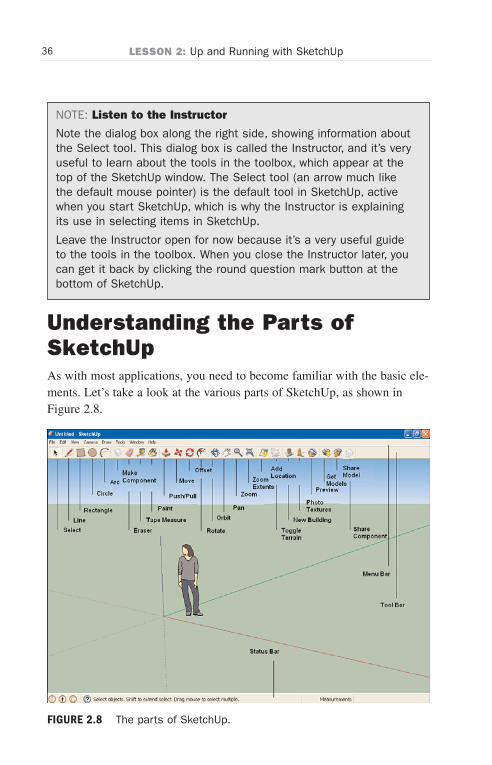
Understanding the Parts ofSketchUpAs with most applications, you need to become familiar with the basic ele-ments. Let’s take a look at the various parts of SketchUp, as shown inFigure 2.8.
FIGURE 2.8 The parts of SketchUp.
Wow! eBook <WoweBook.Com>
ptg6519239
37Using the Orbit Tool
As you’d expect, SketchUp comes with the normal parts of most applica-tions you’re familiar with:
. The menu bar—Includes familiar menus such as File, Edit, andso on. We’ll be making use of the items in SketchUp’s menusthroughout this book.
NOTE: The Getting Started Toolbars
Note that by default, SketchUp shows only its Getting Started tool-bar, which is the toolbar you see in Figure 2.8. To see the full toolset, select the View menu, then the Toolbars item, then the LargeTool Set menu item.
. The toolbar—Includes various drawing tools, as you can seelabeled in Figure 2.8.
. The status bar—Contains buttons to show you who designed thecurrent item open in SketchUp, information about the currentitem, and a Help button (the button with the question mark cap-tion) that turns the Instructor dialog box on and off.
That’s SketchUp in overview. Now let’s start using some tools.
Using the Orbit ToolThere are three primary tools that you have to get familiar with to startworking with SketchUp: Orbit, Pan, and Zoom. We’ll take a look at theOrbit tool in this task and the Pan and Zoom tools in the following twotasks.
The reason that these three tools are the important ones to start out with isthat they give you a handle on working in 2D. New users not familiar withthese tools can grope around in the dark in SketchUp before finally gettinga grip on how to work with 3D.
The Orbit tool lets you examine a 2D figure—called a model inSketchUp—from all different directions. By rotating the Orbit tool, youcan examine the model you’re creating from all angles.
Wow! eBook <WoweBook.Com>
ptg6519239
38 LESSON 2: Up and Running with SketchUp
Here’s how to use the Orbit tool:
1. Start SketchUp. The Welcome to SketchUp dialog box appears.For this task, we’ll work with the Simple Template we’ve used inthe previous tasks.
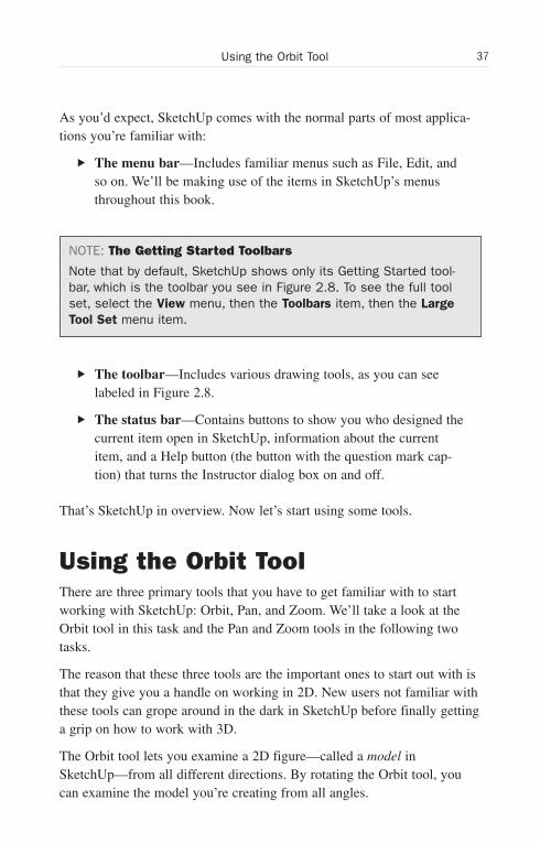
2. Click the Start Using SketchUp button. This opens SketchUpusing the Simple Template from the previous task as the defaulttemplate, as shown in Figure 2.9.
3. Click the Orbit tool in the toolbar (as shown in Figure 2.9).
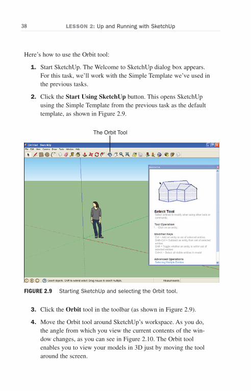
4. Move the Orbit tool around SketchUp’s workspace. As you do,the angle from which you view the current contents of the win-dow changes, as you can see in Figure 2.10. The Orbit toolenables you to view your models in 3D just by moving the toolaround the screen.
The Orbit Tool
FIGURE 2.9 Starting SketchUp and selecting the Orbit tool.
Wow! eBook <WoweBook.Com>
ptg6519239
39Using the Pan Tool
TIP: Experiment with the Orbit Tool
It’s a good idea to play with the Orbit tool for a while, getting usedto what it does, and noting the 3D feeling you get by rotating thecurrent model.
Using the Pan ToolThe Pan tool lets you move from side to side and up and down. The Pantool’s icon is a hand, and that’s appropriate, because you “grasp” the dis-play and move it around.
The angle doesn’t change when you use the Pan tool, unlike when you usethe Orbit tool. Here’s how to put the Pan tool to work:
1. Click the Start Using SketchUp button. This opens SketchUpwith the Simple Template we’ve set as the default in the previoustasks.
FIGURE 2.10 Using the Orbit tool.
Wow! eBook <WoweBook.Com>

ptg6519239
40 LESSON 2: Up and Running with SketchUp
2. Click the Pan tool in the toolbar (shown in Figure 2.11).
3. Press the mouse button in SketchUp’s display to “grasp” thedisplay.
4. Drag the mouse to move the display. When you do, the wholedisplay moves around without changing angle or perspective, asyou can see in Figure 2.11.
The Pan tool gives you a way of viewing your models by moving themfrom side to side and up and down.
Using the Zoom ToolThe Zoom tool lets you zoom in and out of the display—that is, magnifyyour view, if you want to. That’s great to see the smaller details of amodel.
The Pan Tool
FIGURE 2.11 Using the Pan tool.
Wow! eBook <WoweBook.Com>
ptg6519239
41Using the Zoom Tool
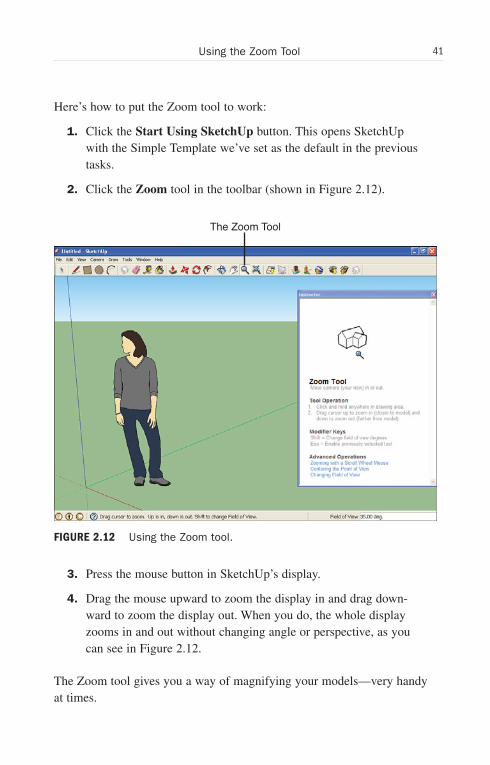
Here’s how to put the Zoom tool to work:
1. Click the Start Using SketchUp button. This opens SketchUpwith the Simple Template we’ve set as the default in the previoustasks.
2. Click the Zoom tool in the toolbar (shown in Figure 2.12).
3. Press the mouse button in SketchUp’s display.
4. Drag the mouse upward to zoom the display in and drag down-ward to zoom the display out. When you do, the whole displayzooms in and out without changing angle or perspective, as youcan see in Figure 2.12.
The Zoom tool gives you a way of magnifying your models—very handyat times.
The Zoom Tool
FIGURE 2.12 Using the Zoom tool.
Wow! eBook <WoweBook.Com>
ptg6519239
42 LESSON 2: Up and Running with SketchUp
TIP: Using the Mouse Wheel to Zoom
If your mouse has a wheel on it, you can zoom in and out just bythumbing the wheel—even if a tool such as the Select tool isselected and not the Zoom tool.
Selecting a Work TemplateUntil now, we’ve been using the first template that SketchUp had tooffer—the Simple Template measured in feet and inches, with a humanfigure in the middle of it, along with blue sky and green earth.
However, you probably don’t want someone standing there in a field undera blue sky when drawing your own models. The most common template touse has no background at all, no sky, no ground—just a set of three axes toshow you the three dimensions.
In this task, we see how to select a good working template that has no fea-tures other than the three axes. Here’s how to set this up:
1. From the Welcome to SketchUp page, click the ChooseTemplate button. The template selection dialog box appears.
2. Click the Engineering–Feet template to select it (as shown inFigure 2.13).
3. Click the Start Using SketchUp button. This opens SketchUpwith the Engineering–Feet template.
4. Select the human figure in the template by clicking it. You cansee the human figure selected in Figure 2.14.
5. Delete the human figure by pressing the Del key. The figure dis-appears. You now have a clean slate for creating your own mod-els without any distracting backgrounds.
The Engineering–Feet or Engineering–Meters templates are useful becausethey don’t give you a background, so you’re free to design your own. We’lluse these templates frequently in this book.
Wow! eBook <WoweBook.Com>

ptg6519239
43Selecting a Work Template
FIGURE 2.13 Selecting the Engineering–Feet template.
FIGURE 2.14 Selecting the human figure.
Wow! eBook <WoweBook.Com>
ptg6519239
44 LESSON 2: Up and Running with SketchUp
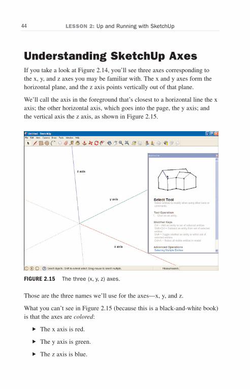
Understanding SketchUp AxesIf you take a look at Figure 2.14, you’ll see three axes corresponding tothe x, y, and z axes you may be familiar with. The x and y axes form thehorizontal plane, and the z axis points vertically out of that plane.
We’ll call the axis in the foreground that’s closest to a horizontal line the xaxis; the other horizontal axis, which goes into the page, the y axis; andthe vertical axis the z axis, as shown in Figure 2.15.
Those are the three names we’ll use for the axes—x, y, and z.
What you can’t see in Figure 2.15 (because this is a black-and-white book)is that the axes are colored:
. The x axis is red.
. The y axis is green.
. The z axis is blue.
FIGURE 2.15 The three (x, y, z) axes.
Wow! eBook <WoweBook.Com>
ptg6519239
45Understanding Edges and Surfaces
TIP: Axes Coloring
You’ll sometimes see axes referred to by color in the SketchUphelp files, so it can be helpful to bear the previous list of colorassociations in mind.
The reason the axes are colored is that the shapes you draw (see the nextlesson) are usually aligned with one or another axis by SketchUp automat-ically, and SketchUp will indicate the color axis the shape is being alignedwith. So, for example, as you draw one edge of a rectangle, a ToolTip (asmall yellow window with some text) will appear, reading On Red Axis toshow that your drawing action is being aligned with the x (red) axis. Thisis helpful because by default SketchUp automatically snaps what you drawto be parallel to an axis to let you draw shapes easily without wonderinghow they will line up with the axes. This will become more apparent as westart to draw shapes in coming sections.
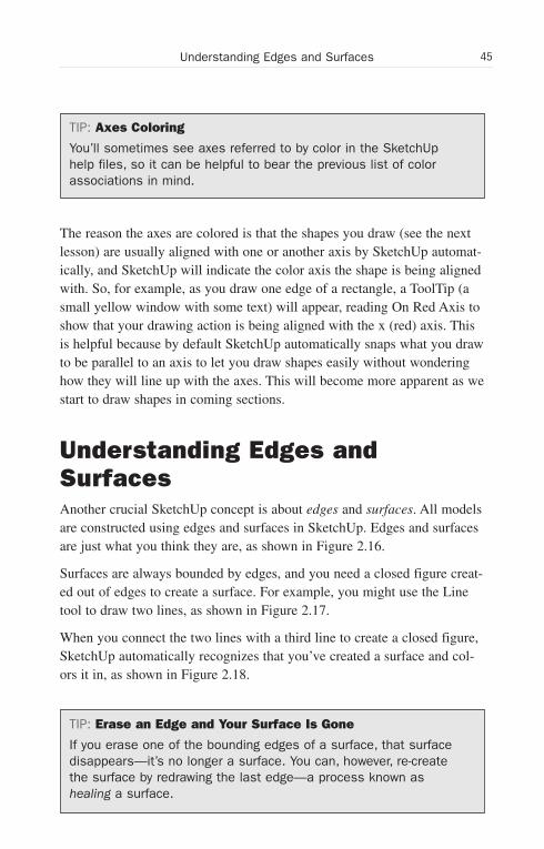
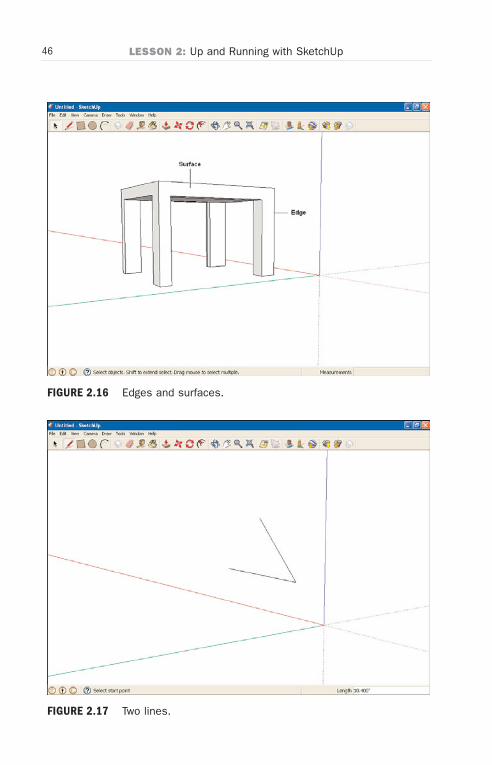
Understanding Edges andSurfacesAnother crucial SketchUp concept is about edges and surfaces. All modelsare constructed using edges and surfaces in SketchUp. Edges and surfacesare just what you think they are, as shown in Figure 2.16.
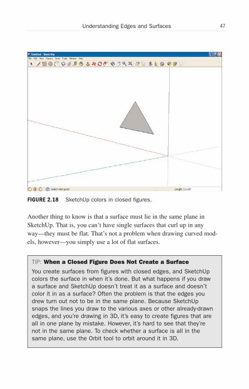
Surfaces are always bounded by edges, and you need a closed figure creat-ed out of edges to create a surface. For example, you might use the Linetool to draw two lines, as shown in Figure 2.17.
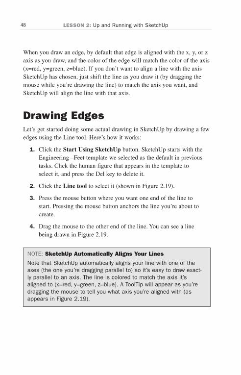
When you connect the two lines with a third line to create a closed figure,SketchUp automatically recognizes that you’ve created a surface and col-ors it in, as shown in Figure 2.18.
TIP: Erase an Edge and Your Surface Is Gone
If you erase one of the bounding edges of a surface, that surfacedisappears—it’s no longer a surface. You can, however, re-createthe surface by redrawing the last edge—a process known ashealing a surface.
Wow! eBook <WoweBook.Com>
ptg6519239
46 LESSON 2: Up and Running with SketchUp
FIGURE 2.16 Edges and surfaces.
FIGURE 2.17 Two lines.
Wow! eBook <WoweBook.Com>
ptg6519239
47Understanding Edges and Surfaces
FIGURE 2.18 SketchUp colors in closed figures.
Another thing to know is that a surface must lie in the same plane inSketchUp. That is, you can’t have single surfaces that curl up in anyway—they must be flat. That’s not a problem when drawing curved mod-els, however—you simply use a lot of flat surfaces.
TIP: When a Closed Figure Does Not Create a Surface
You create surfaces from figures with closed edges, and SketchUpcolors the surface in when it’s done. But what happens if you drawa surface and SketchUp doesn’t treat it as a surface and doesn’tcolor it in as a surface? Often the problem is that the edges youdrew turn out not to be in the same plane. Because SketchUpsnaps the lines you draw to the various axes or other already-drawnedges, and you’re drawing in 3D, it’s easy to create figures that areall in one plane by mistake. However, it’s hard to see that they’renot in the same plane. To check whether a surface is all in thesame plane, use the Orbit tool to orbit around it in 3D.
Wow! eBook <WoweBook.Com>
ptg6519239
48 LESSON 2: Up and Running with SketchUp
When you draw an edge, by default that edge is aligned with the x, y, or zaxis as you draw, and the color of the edge will match the color of the axis(x=red, y=green, z=blue). If you don’t want to align a line with the axisSketchUp has chosen, just shift the line as you draw it (by dragging themouse while you’re drawing the line) to match the axis you want, andSketchUp will align the line with that axis.
Drawing EdgesLet’s get started doing some actual drawing in SketchUp by drawing a fewedges using the Line tool. Here’s how it works:
1. Click the Start Using SketchUp button. SketchUp starts with theEngineering –Feet template we selected as the default in previoustasks. Click the human figure that appears in the template toselect it, and press the Del key to delete it.
2. Click the Line tool to select it (shown in Figure 2.19).
3. Press the mouse button where you want one end of the line tostart. Pressing the mouse button anchors the line you’re about tocreate.
4. Drag the mouse to the other end of the line. You can see a linebeing drawn in Figure 2.19.
NOTE: SketchUp Automatically Aligns Your Lines
Note that SketchUp automatically aligns your line with one of theaxes (the one you’re dragging parallel to) so it’s easy to draw exact-ly parallel to an axis. The line is colored to match the axis it’saligned to (x=red, y=green, z=blue). A ToolTip will appear as you’redragging the mouse to tell you what axis you’re aligned with (asappears in Figure 2.19).
Wow! eBook <WoweBook.Com>

ptg6519239
49Drawing Edges
The LineTool
FIGURE 2.19 Use the mouse and the Line tool to draw.
5. Release the mouse button to complete the line. When you releasethe mouse button, your new line is drawn and becomes an edge.
Congratulations—you’ve created a new edge.
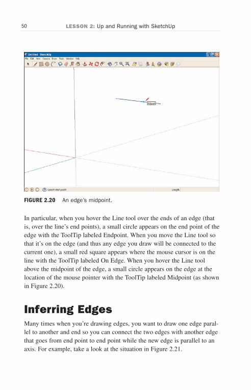
To make it easy to draw other edges that connect to this edge, SketchUplabels various points on the edge as you let the Line tool roll over theedge, as you can see in Figure 2.20.
TIP: Connecting Edges
When you draw an edge that you want to connect to another edge,you typically let the mouse hover over an end point of the first edgeuntil the end point circle and the ToolTip labeled Endpoint appears.Press the mouse button over the end point and then draw the nextedge.
Wow! eBook <WoweBook.Com>
ptg6519239
50 LESSON 2: Up and Running with SketchUp
FIGURE 2.20 An edge’s midpoint.
In particular, when you hover the Line tool over the ends of an edge (thatis, over the line’s end points), a small circle appears on the end point of theedge with the ToolTip labeled Endpoint. When you move the Line tool sothat it’s on the edge (and thus any edge you draw will be connected to thecurrent one), a small red square appears where the mouse cursor is on theline with the ToolTip labeled On Edge. When you hover the Line toolabove the midpoint of the edge, a small circle appears on the edge at thelocation of the mouse pointer with the ToolTip labeled Midpoint (as shownin Figure 2.20).
Inferring EdgesMany times when you’re drawing edges, you want to draw one edge paral-lel to another and end so you can connect the two edges with another edgethat goes from end point to end point while the new edge is parallel to anaxis. For example, take a look at the situation in Figure 2.21.
Wow! eBook <WoweBook.Com>

ptg6519239
51Inferring Edges
There are two edges there—now suppose you want to draw a third edge onyour way to making a rectangle. The third edge will be at the bottom ofthe figure, parallel to the top edge.
But how far should you draw the bottom edge so that its end point will bedirectly under the corresponding end point of the top edge? You can guessvisually where to stop drawing the third edge so that its end point will endup right under the top edge’s end point, but SketchUp provides you with abetter way.
Because this is such a common operation—ending an edge at the correctlocation to match another edge’s end point—SketchUp has a special namefor it: inferring. When you infer an edge, you align it with another edge sothat its end point is ready to be connected to another edge’s end point witha new edge that is parallel to an axis.
FIGURE 2.21 The need for inferring an edge.
Wow! eBook <WoweBook.Com>
ptg6519239
52 LESSON 2: Up and Running with SketchUp
Here’s how inferring works, making it easy to draw figures so that alledges line up with axes:
1. Click the Start Using SketchUp button. SketchUp starts with theEngineering–Feet template we selected as the default in previoustasks. Click the human figure that appears in the template toselect it, and press the Del key to delete it.
2. Click the Line tool to select it.
3. Draw two edges like those in Figure 2.21.
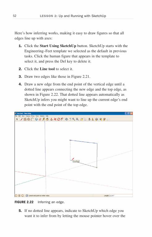
4. Draw a new edge from the end point of the vertical edge until adotted line appears connecting the new edge and the top edge, asshown in Figure 2.22. That dotted line appears automatically asSketchUp infers you might want to line up the current edge’s endpoint with the end point of the top edge.
5. If no dotted line appears, indicate to SketchUp which edge youwant it to infer from by letting the mouse pointer hover over the
FIGURE 2.22 Inferring an edge.
Wow! eBook <WoweBook.Com>
ptg6519239
53Inferring Edges
top edge for two seconds. This establishes which edge you wantto infer from, in case SketchUp doesn’t guess right. After lettingthe mouse hover over the edge you want to infer from for twoseconds, redraw the third edge, and the dotted line connecting theend points should appear.
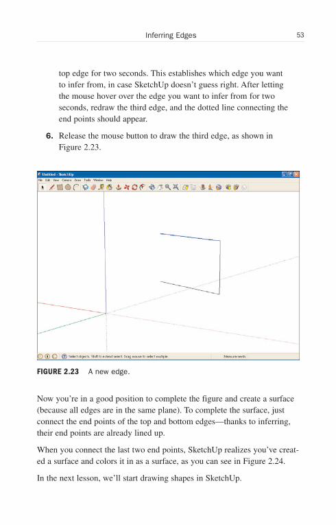
6. Release the mouse button to draw the third edge, as shown inFigure 2.23.
Now you’re in a good position to complete the figure and create a surface(because all edges are in the same plane). To complete the surface, justconnect the end points of the top and bottom edges—thanks to inferring,their end points are already lined up.
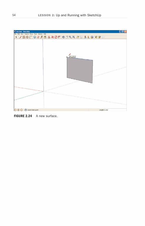
When you connect the last two end points, SketchUp realizes you’ve creat-ed a surface and colors it in as a surface, as you can see in Figure 2.24.
In the next lesson, we’ll start drawing shapes in SketchUp.
FIGURE 2.23 A new edge.
Wow! eBook <WoweBook.Com>
ptg6519239
54 LESSON 2: Up and Running with SketchUp
FIGURE 2.24 A new surface.
Wow! eBook <WoweBook.Com>

ptg6519239
LESSON 3
Drawing Shapes: Lines,Rectangles, Polygons,and Circles
In this lesson, you’ll see how to create shapes—rectangles, circles, arcs,and so on. Those are the basic shapes you create other shapes from inSketchUp, and learning how to handle each of these is important.
Getting StartedBear in mind that what you learned about edges and surfaces in the previ-ous lesson applies here. In particular, it’s important to make sure that youdon’t draw any edge over any other edge.
TIP: Crossing Edges
If it looks like you have to draw figures that cross edges, such as aline going across a rectangle, don’t. Instead, draw the line up tothe rectangle’s edge, then draw a new line inside the rectangle tocontinue. Always remember: don’t cross edges, because it confus-es SketchUp. We’ll see when you can bend this rule later.
Let’s jump in immediately by drawing some lines (that is, edges).
TIP: Selecting a Template
In this and the following lessons, we’re going to be using theEngineering template in SketchUp so that we have no backgroundto get in the way. You’re free to select your own template, of course(see Lesson 2, “Up and Running with SketchUp”), but the
Wow! eBook <WoweBook.Com>
ptg6519239
56 LESSON 3: Drawing Shapes: Lines, Rectangles, Polygons, and Circles
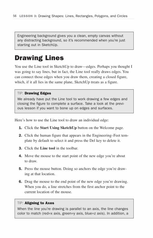
Engineering background gives you a clean, empty canvas withoutany distracting background, so it’s recommended when you’re juststarting out in SketchUp.
Drawing LinesYou use the Line tool in SketchUp to draw—edges. Perhaps you thought Iwas going to say lines, but in fact, the Line tool really draws edges. Youcan connect those edges when you draw them, creating a closed figure,which, if it all lies in the same plane, SketchUp treats as a figure.
TIP: Drawing Edges
We already have put the Line tool to work drawing a few edges andclosing the figure to complete a surface. Take a look at the previ-ous lesson if you want to bone up on edges and surfaces.
Here’s how to use the Line tool to draw an individual edge:
1. Click the Start Using SketchUp button on the Welcome page.
2. Click the human figure that appears in the Engineering–Feet tem-plate by default to select it and press the Del key to delete it.
3. Click the Line tool in the toolbar.
4. Move the mouse to the start point of the new edge you’re aboutto draw.
5. Press the mouse button. Doing so anchors the edge you’re draw-ing at that location.
6. Drag the mouse to the end point of the new edge you’re drawing.When you do, a line stretches from the first anchor point to thecurrent location of the mouse.
TIP: Aligning to Axes
When the line you’re drawing is parallel to an axis, the line changescolor to match (red=x axis, green=y axis, blue=z axis). In addition, a
Wow! eBook <WoweBook.Com>
ptg6519239
57Drawing Multiline Shapes
ToolTip will appear at the mouse cursor location. Notice also thatwhen you draw, the line will align to other edges as well for yourconvenience. And if you don’t want them aligned to other edges,just keep dragging the mouse until the line snaps to a new align-ment.
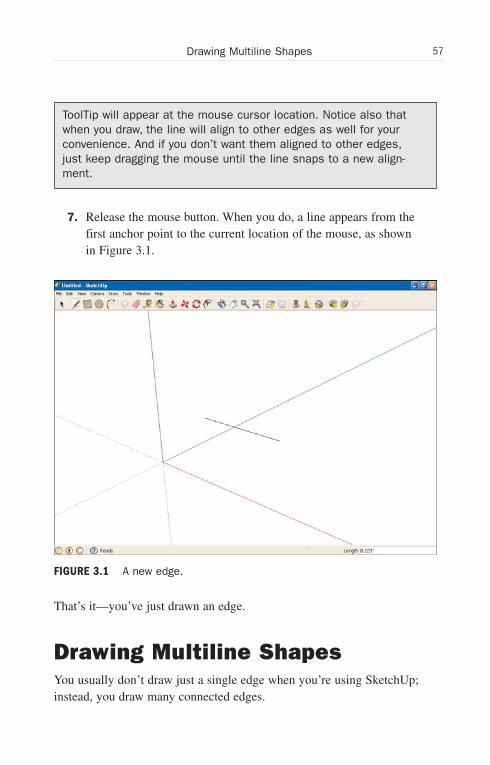
7. Release the mouse button. When you do, a line appears from thefirst anchor point to the current location of the mouse, as shownin Figure 3.1.
That’s it—you’ve just drawn an edge.
Drawing Multiline ShapesYou usually don’t draw just a single edge when you’re using SketchUp;instead, you draw many connected edges.
FIGURE 3.1 A new edge.
Wow! eBook <WoweBook.Com>
ptg6519239
58 LESSON 3: Drawing Shapes: Lines, Rectangles, Polygons, and Circles
It’s not hard to draw a new edge connecting to an existing edge inSketchUp. When you’re drawing the new edge and approach any existingedges, you’ll see a red square appear on the existing edge when you’re onthat edge. That means that releasing the mouse will connect your new edgeto the existing one. When you’re near an end point, a circle colored ingreen will appear on the existing edge at the end point, and a cyan circlewill appear for the midpoint,
TIP: Watch the ToolTips
There’s no need to try to memorize the various red squares andcyan or green circles that appear on edges when you’re connectingother edges to them—ToolTips will also appear, labeled Endpoint,On Edge, and so on.
So although you can connect one edge to another, it’s a little tedious.SketchUp recommends instead that you draw multiple edges all at once, ifyou can. That way, you can just “connect the dots” to draw a new figure,and SketchUp will keep drawing new edges as long as you move themouse. Because it realizes you’re drawing multiple edges, SketchUp keepsdrawing lines until you tell it to stop by hitting the Esc key.
Here’s how to use the Line tool to draw multiline figures working with theEngineering–Feet template set in the previous task:
1. Click the Start Using SketchUp button and delete the humanfigure that appears by default.
2. Click the Line tool in the toolbar.
3. Move the mouse to the start point of the new edge you’re aboutto draw and click the mouse.
4. Move the mouse to the end point of the new edge—which is alsothe start point of the new edge—and click it.
5. Repeat step 5 for all the new edges in your drawing. SketchUpwill keep drawing edges between the locations you click in yourdrawing.
Wow! eBook <WoweBook.Com>
ptg6519239
59Drawing Measured Lines
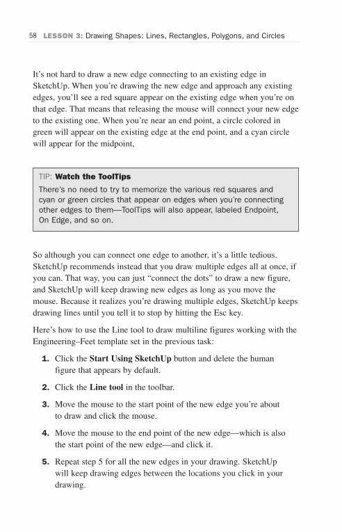
6. Press Esc to make SketchUp stop drawing edges. SketchUp willstop drawing edges, and your multiline figure is complete, asshown in Figure 3.2.
In this way, SketchUp makes drawing a multi-edge figure easy.
Drawing Measured LinesYou can also tell SketchUp just how long you want your edges to be whenyou draw them. Note that we are still working with the Engineering–Feettemplate set in the previous task.
Here’s how to draw measured edges:
1. Click the Start Using SketchUp button.
2. Click the Line tool in the toolbar.
3. Move the mouse to the start point of the new edge you’re aboutto draw and click the mouse.
FIGURE 3.2 Drawing a multiline figure.
Wow! eBook <WoweBook.Com>

ptg6519239
60 LESSON 3: Drawing Shapes: Lines, Rectangles, Polygons, and Circles
4. Move the mouse toward the end point of the new edge.
5. Enter the length of the new edge. You can enter the following:
. cm to signify centimeters
. m to signify meters
. ' for feet
. " for inches
Thus, for example, 5m means five meters, 5" means five inches,and so on.
6. Press Enter. SketchUp draws the new edge with the lengthyou’ve requested.
Being able to set the length of edges is crucial for engineering and archi-tectural drawings.
Drawing RectanglesIt takes only two clicks to draw a rectangle in SketchUp. Of course, rec-tangles are surfaces, so when you’re done drawing one, SketchUp willcolor it as a surface.
Bear in mind that according to SketchUp rules, no rectangle should evercross another rectangle or any other edge, for that matter. However, it’sfine to draw a rectangle so that an edge lies on top of an edge from anotherfigure, such as another rectangle.
Here’s how to use the Rectangle tool:
1. Click the Start Using SketchUp button and delete the humanfigure that appears within the Engineering–Feet template.
2. Click the Rectangle tool in the toolbar (shown in Figure 3.3).
3. Move the mouse to one corner of the new rectangle you’re aboutto draw and click the mouse.
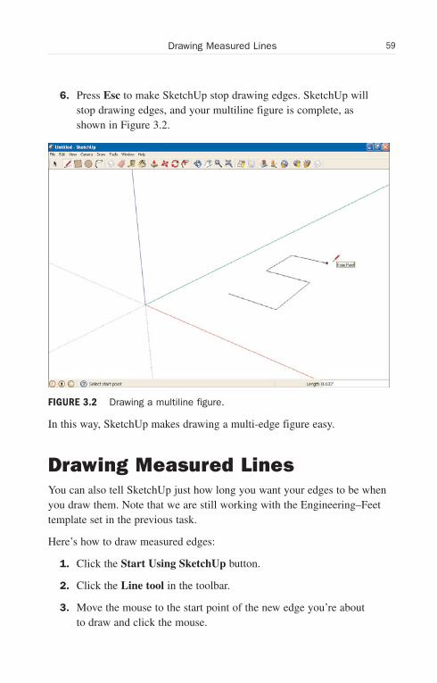
4. Move the mouse to the opposite corner of the rectangle and clickit. SketchUp will draw the rectangle, as shown in Figure 3.3.
As you can see, it’s simple to draw rectangles.
Wow! eBook <WoweBook.Com>
ptg6519239
61Drawing Rectangles
The RectangleTool
FIGURE 3.3 Drawing a rectangle.
TIP: Dragging Rectangles
You can also press the mouse button at one corner of the rectan-gle and then drag the mouse to the opposite corner, then releasethe mouse to draw the rectangle. It’s easier to click the mouseonce in one corner and then in the opposite corner if you’re creat-ing measured rectangles. See the next task.
Drawing Measured RectanglesYou can also give SketchUp the dimensions you want your rectangle to beas you draw it.
Here’s how to create measured rectangles:
1. Click the Start Using SketchUp button and delete the humanfigure that appears within the Engineering–Feet template.
2. Click the Rectangle tool in the toolbar.
Wow! eBook <WoweBook.Com>

ptg6519239
62 LESSON 3: Drawing Shapes: Lines, Rectangles, Polygons, and Circles
3. Move the mouse to one corner of the new rectangle you’re aboutto draw and click the mouse.
4. Move the mouse toward the opposite corner of the new rectangle.
5. Enter the dimensions of the new rectangle, separated by commas.You can enter these units:
. cm to signify centimeters
. m to signify meters
. ' for feet
. " for inches.
For example, to draw a rectangle of 5 meters by 6 meters, enter 5m, 6m.
6. Press Enter. SketchUp draws the new rectangle with the lengthyou’ve requested.
Being able to set the dimensions of rectangles is useful for drawing plans,as in engineering and architectural drawings.
Drawing CirclesThe Circle tool does just as you’d expect; it draws circles. That is, italmost does—in fact, what it does is draw 24-sided polygons by default ascircles. You can set the number of sides to anything you want, however.
TIP: The Polygon Tool Versus the Circle Tool
So circles are really polygons in SketchUp, and they default to 24sides. Interestingly, SketchUp also has a polygon tool, and itdefaults to six sides. But if you set the tools to the same numberof sides, they draw identical surfaces. So what’s the difference?The difference comes when you push or pull the circle or polygoninto 3D, as we’ll do soon. No matter how many sides it has, a cir-cle will give you cylindrical sides when you pull it into 3D, whereasa polygon will retain the number of sides the face has on the partthat’s cylindrical for a circle being dragged into 3D. So if you draw avertical pillar with a top that’s a circle, the sides of the pillar will bea smooth cylinder. But if the top face of the pillar is a polygon, the
Wow! eBook <WoweBook.Com>
ptg6519239
63Drawing Circles
sides of the pillar will have the same number of sides as the poly-gon. That’s the only real difference between circles and polygons(other than the default number of sides for circles is 24, and thedefault number of sides for polygons is 6).
Here’s how to use the Circle tool:
1. Click the Start Using SketchUp button and delete the humanfigure that appears within the Engineering–Feet template.
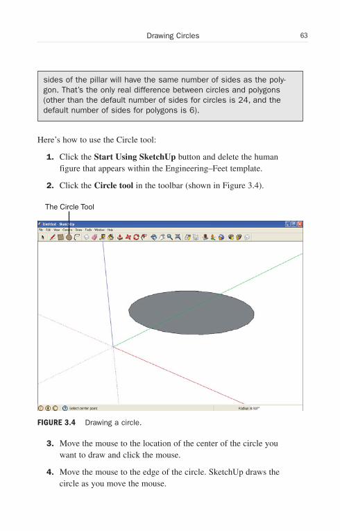
2. Click the Circle tool in the toolbar (shown in Figure 3.4).
3. Move the mouse to the location of the center of the circle youwant to draw and click the mouse.
4. Move the mouse to the edge of the circle. SketchUp draws thecircle as you move the mouse.
The Circle Tool
FIGURE 3.4 Drawing a circle.
Wow! eBook <WoweBook.Com>
ptg6519239
64 LESSON 3: Drawing Shapes: Lines, Rectangles, Polygons, and Circles
5. Click the mouse. SketchUp draws the circle permanently (unlessyou erase it, of course).
And that’s it for drawing circles. When a circle has been drawn, it’s a sur-face, and SketchUp colors it in, as you can see in Figure 3.4.
TIP: Dragging Circles
Just as you can with rectangles, you can also press the mouse but-ton at the center of a circle you want to draw, drag the mouse tothe edge of the circle, and then release the mouse to draw a circle.It’s easier to click the mouse once in the center and then on theedge if you’re creating measured circles, however; see the nexttask.
Drawing Measured CirclesJust as you can with any other figure, you can give SketchUp a size for thecircle you’re drawing, as you draw it.
Here’s how to create measured circles:
1. Click the Circle tool in the toolbar.
2. Move the mouse to the location of the center of the circle youwant to draw and click the mouse.
3. Move the mouse toward the edge of the new circle.
4. Enter the radius measurement of the new circle. You can enterthese units:
. cm to signify centimeters
. m to signify meters
. ' for feet
. " for inches.
For example, to draw a circle with a radius of 5 meters, enter 5m.
5. Press Enter. SketchUp draws the new circle with the radiusyou’ve requested.
When the circle has been drawn, it’s a surface, as mentioned in the previous task, and SketchUp colors it in.
When the circle has been drawn, it’s a surface, as mentioned in the previous task, and SketchUp colors it in.
Wow! eBook <WoweBook.Com>
ptg6519239
65Drawing Polygons
Drawing PolygonsYou can also draw polygons with SketchUp. Presumably because you candraw polygons with the circle tool (see the task after next), the Polygontool doesn’t appear on the Getting Started toolbar that we’ve been using,so we’ll have to use the “large” toolbar here to access the Polygon tool.
Here’s how to use the Polygon tool:
1. Click the Start Using SketchUp button.
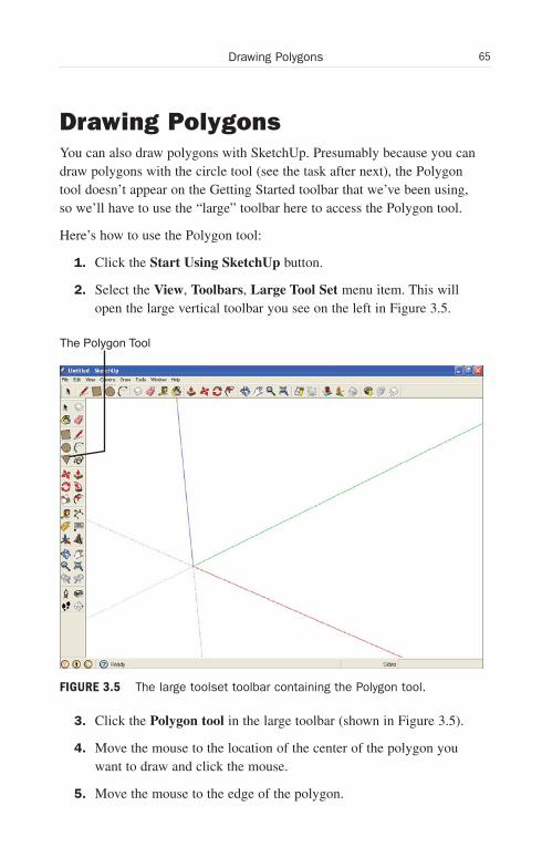
2. Select the View, Toolbars, Large Tool Set menu item. This willopen the large vertical toolbar you see on the left in Figure 3.5.
3. Click the Polygon tool in the large toolbar (shown in Figure 3.5).
4. Move the mouse to the location of the center of the polygon youwant to draw and click the mouse.
5. Move the mouse to the edge of the polygon.
The Polygon Tool
FIGURE 3.5 The large toolset toolbar containing the Polygon tool.
Wow! eBook <WoweBook.Com>
ptg6519239
66 LESSON 3: Drawing Shapes: Lines, Rectangles, Polygons, and Circles
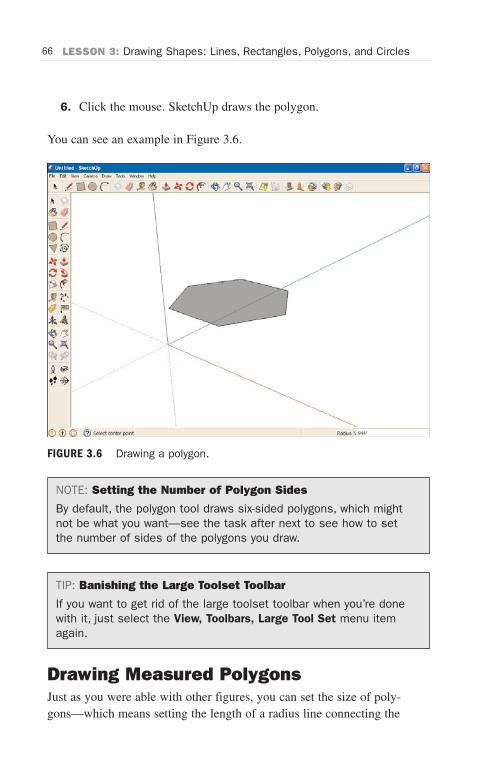
6. Click the mouse. SketchUp draws the polygon.
You can see an example in Figure 3.6.
NOTE: Setting the Number of Polygon Sides
By default, the polygon tool draws six-sided polygons, which mightnot be what you want—see the task after next to see how to setthe number of sides of the polygons you draw.
TIP: Banishing the Large Toolset Toolbar
If you want to get rid of the large toolset toolbar when you’re donewith it, just select the View, Toolbars, Large Tool Set menu itemagain.
Drawing Measured PolygonsJust as you were able with other figures, you can set the size of poly-gons—which means setting the length of a radius line connecting the
FIGURE 3.6 Drawing a polygon.
Wow! eBook <WoweBook.Com>
ptg6519239
67Setting the Number of Sides of Circles or Polygons
center of a polygon to a side so that the connecting line is perpendicular tothe side.
Here’s how to set the size of polygons:
1. Click the Start Using SketchUp button.
2. Select the View, Toolbars, Large Tool Set menu item. This willopen the large toolset’s vertical toolbar.
3. Click the Polygon tool in the large toolbar.
4. Move the mouse to the location of the center of the polygon youwant to draw and click the mouse.
5. Move the mouse toward the edge of the new polygon.
6. Enter the radius measurement of the new polygon. You can enterthese units:
. cm to signify centimeters
. m to signify meters
. ' for feet
. " for inches.
For example, to draw a polygon with a radius of 5 meters, enter 5m.
7. Press Enter. SketchUp draws the new polygon with the radiusyou’ve requested.
When the polygon has been drawn, it’s a surface, and SketchUp colors it in.
Setting the Number of Sides ofCircles or PolygonsBy default, the Polygon tool draws polygons of six sides, and the circletool draws “circles” of 24 sides. But you may need a triangle. So how doyou set the number of sides of a figure as you’re drawing it?
Follow these steps to set the number of sides of a circle or polygon:
1. If necessary, select the View, Toolbars, Large Tool Set menuitem.
Wow! eBook <WoweBook.Com>
ptg6519239
68 LESSON 3: Drawing Shapes: Lines, Rectangles, Polygons, and Circles
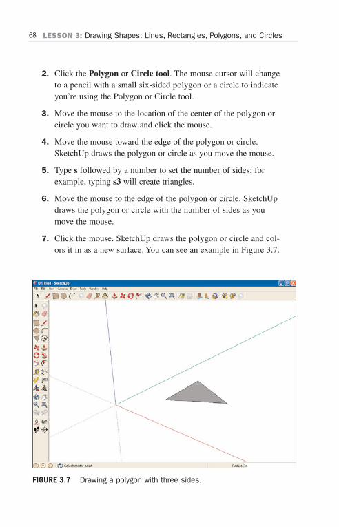
2. Click the Polygon or Circle tool. The mouse cursor will changeto a pencil with a small six-sided polygon or a circle to indicateyou’re using the Polygon or Circle tool.
3. Move the mouse to the location of the center of the polygon orcircle you want to draw and click the mouse.
4. Move the mouse toward the edge of the polygon or circle.SketchUp draws the polygon or circle as you move the mouse.
5. Type s followed by a number to set the number of sides; forexample, typing s3 will create triangles.
6. Move the mouse to the edge of the polygon or circle. SketchUpdraws the polygon or circle with the number of sides as youmove the mouse.
7. Click the mouse. SketchUp draws the polygon or circle and col-ors it in as a new surface. You can see an example in Figure 3.7.
FIGURE 3.7 Drawing a polygon with three sides.
Wow! eBook <WoweBook.Com>
ptg6519239
69Orienting Shapes
Note that you can use this technique with both the Polygon and Circletools. The only difference between these two is when you push or pull thefigure into 3D (as explained earlier in the “Drawing Circles” task).
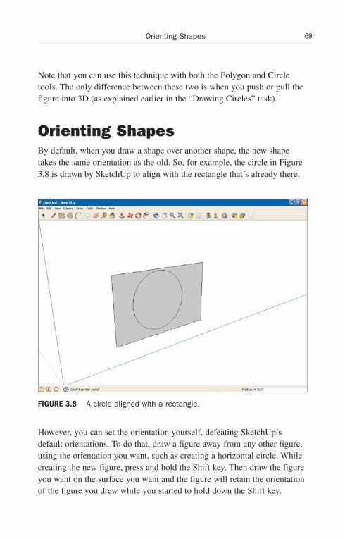
Orienting ShapesBy default, when you draw a shape over another shape, the new shapetakes the same orientation as the old. So, for example, the circle in Figure3.8 is drawn by SketchUp to align with the rectangle that’s already there.
However, you can set the orientation yourself, defeating SketchUp’sdefault orientations. To do that, draw a figure away from any other figure,using the orientation you want, such as creating a horizontal circle. Whilecreating the new figure, press and hold the Shift key. Then draw the figureyou want on the surface you want and the figure will retain the orientationof the figure you drew while you started to hold down the Shift key.
FIGURE 3.8 A circle aligned with a rectangle.
Wow! eBook <WoweBook.Com>
ptg6519239
70 LESSON 3: Drawing Shapes: Lines, Rectangles, Polygons, and Circles
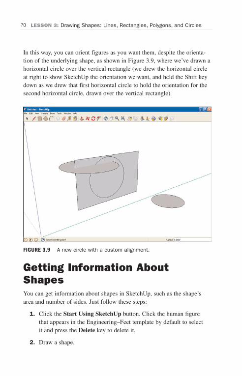
In this way, you can orient figures as you want them, despite the orienta-tion of the underlying shape, as shown in Figure 3.9, where we’ve drawn ahorizontal circle over the vertical rectangle (we drew the horizontal circleat right to show SketchUp the orientation we want, and held the Shift keydown as we drew that first horizontal circle to hold the orientation for thesecond horizontal circle, drawn over the vertical rectangle).
Getting Information AboutShapesYou can get information about shapes in SketchUp, such as the shape’sarea and number of sides. Just follow these steps:
1. Click the Start Using SketchUp button. Click the human figurethat appears in the Engineering–Feet template by default to selectit and press the Delete key to delete it.
2. Draw a shape.
FIGURE 3.9 A new circle with a custom alignment.
Wow! eBook <WoweBook.Com>
ptg6519239
71Getting Information About Shapes
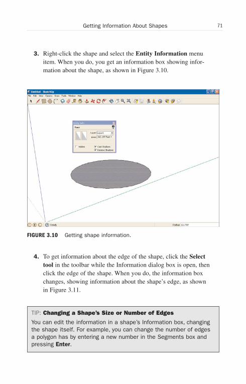
3. Right-click the shape and select the Entity Information menuitem. When you do, you get an information box showing infor-mation about the shape, as shown in Figure 3.10.
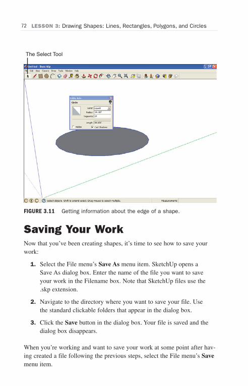
4. To get information about the edge of the shape, click the Selecttool in the toolbar while the Information dialog box is open, thenclick the edge of the shape. When you do, the information boxchanges, showing information about the shape’s edge, as shownin Figure 3.11.
TIP: Changing a Shape’s Size or Number of Edges
You can edit the information in a shape’s Information box, changingthe shape itself. For example, you can change the number of edgesa polygon has by entering a new number in the Segments box andpressing Enter.
FIGURE 3.10 Getting shape information.
Wow! eBook <WoweBook.Com>
ptg6519239
72 LESSON 3: Drawing Shapes: Lines, Rectangles, Polygons, and Circles
The Select Tool
FIGURE 3.11 Getting information about the edge of a shape.
Saving Your WorkNow that you’ve been creating shapes, it’s time to see how to save yourwork:
1. Select the File menu’s Save As menu item. SketchUp opens aSave As dialog box. Enter the name of the file you want to saveyour work in the Filename box. Note that SketchUp files use the.skp extension.
2. Navigate to the directory where you want to save your file. Usethe standard clickable folders that appear in the dialog box.
3. Click the Save button in the dialog box. Your file is saved and thedialog box disappears.
When you’re working and want to save your work at some point after hav-ing created a file following the previous steps, select the File menu’s Savemenu item.
Wow! eBook <WoweBook.Com>
ptg6519239
LESSON 4
Drawing Shapes: Arcs,Freehand, Text, and 3DText
In this lesson, we cover how to draw arcs, how to draw freehand, and howto draw text.
Arcs, Freehand, and TextThere’s a lot to see here—particularly with arcs, because they’re a com-mon edge element you use to draw curves in models. Drawing freehand isalso cool, but a little hard to control because you draw with the mouse.Finally, we’ll see how to draw text in both 2D and 3D.
Let’s get started with arcs.
Drawing ArcsDrawing arcs is a three-step process in SketchUp—you click at one anchorpoint, click at another, and then pull the arc (SketchUp will bend it as youpull) into place.
TIP: An Arc Actually Has 12 Sides
Just as circles are made up, by default, of 24 sides in SketchUp(see Lesson 2, “Up and Running with SketchUp”), arcs are madeup of 12 segments. If you’re drawing a large arc, those sides,which are really line segments, might be visible. To fix that, you canset the number of sides in an arc. We’ll see how in the task“Setting the Number of Arc Segments,” a bit later.
Wow! eBook <WoweBook.Com>

ptg6519239
74 LESSON 4: Drawing Shapes: Arcs, Freehand, Text, and 3D Text
The Arc Tool
FIGURE 4.1 The Arc tool and a new arc.
Let’s take a look at how to create arcs now.
1. Click the Start Using SketchUp button and click the human fig-ure that appears in the Engineering–Feet template to select it;press the Del key to delete it.
2. Click the Arc tool in the toolbar (shown in Figure 4.1).
3. Move the mouse to the start point of the new arc you’re about todraw and click the mouse. When you do, you anchor an end pointof the arc you’re drawing at that location.
4. Move the mouse to the end point of the new arc you’re drawingand click the mouse. When you do, a line appears from the firstanchor point to the current location of the mouse.
5. Slide the mouse along the line between the two end points, andmove the mouse to “pull” the line out into an arc. When you do,an arc appears from the first anchor point to the current locationof the mouse.
Wow! eBook <WoweBook.Com>

ptg6519239
75Drawing Measured Arcs
TIP: Inferring Arcs to Planes
Note that as you stretch your arc, SketchUp will infer it to differentaxes or underlying surfaces (that is, draw it in the plane defined bytwo axes or an underlying surface). Keep pulling the arc until itsnaps to the plane you want to draw it in, if that becomes anissue.
6. Click the mouse. The arc becomes permanent (unless you eraseit, of course). You can see an arc in Figure 4.1.
That’s it—you’ve just drawn an arc.
TIP: Drawing Perfect Half Circles
Want to draw a perfect half circle? Just keep pulling an arc until theToolTip at the location of the mouse reads Half Circle; then clickthe mouse.
Drawing Measured ArcsPerhaps you want to create an arc a bit more precisely than you can free-hand. You can specify the radius of any arc; here’s how:
1. Click the Start Using SketchUp button and click the human fig-ure that appears in the Engineering–Feet template to select it;press the Del key to delete it.
2. Click the Arc tool in the toolbar (shown in Figure 4.1).
3. Move the mouse to the start point of the new arc you’re about todraw and click the mouse. When you do, you anchor an end pointof the arc you’re drawing at that location.
4. Move the mouse to the end point of the new arc you’re drawingand click the mouse. When you do, a line appears from the firstanchor point to the current location of the mouse.
5. Slide the mouse along the line between the two end points, andmove the mouse to “pull” the line out into an arc. When you do,an arc appears from the first anchor point to the current locationof the mouse.
Wow! eBook <WoweBook.Com>

ptg6519239
76 LESSON 4: Drawing Shapes: Arcs, Freehand, Text, and 3D Text
6. Enter the size of the radius you want (simply stop using themouse and type in the radius; no dialog box or text fieldappears). You can use the following:
. cm to signify centimeters
. m to signify meters
. ' for feet
. " for inches.
Thus, for example, 5m means five meters, 5" means five inches,and so on.
7. Press Enter. SketchUp draws the new arc with the radius you’verequested.
And there you have it—an arc with a specific radius.
Drawing Arcs Tangent to CornersConsider the shape in Figure 4.2. Suppose that you want to round theacute angle in that figure—how would you do it?
FIGURE 4.2 A shape with an acute angle.
Wow! eBook <WoweBook.Com>

ptg6519239
77Drawing Arcs Tangent to Corners
You could draw an arc so that it was tangent to the two sides, as shown inFigure 4.3.
Then you could use the Eraser tool to erase the unneeded acute angle, asshown in Figure 4.4.
That’s it—you’ve rounded the acute angle. Here’s how it works step by step:
1. Click the Start Using SketchUp button and delete the humanfigure that appears in Engineering–Feet.
2. Draw the surface similar to the one shown in Figure 4.2 with theangle you want to round.
3. Click the Arc tool in the toolbar and move the mouse to the startpoint of the new arc you’re about to draw. The start point shouldbe on an edge adjacent to the angle you want to round.
4. Click the mouse. When you do, you anchor an end point of thearc you’re drawing at that location.
FIGURE 4.3 The same shape with a tangent arc added.
Wow! eBook <WoweBook.Com>
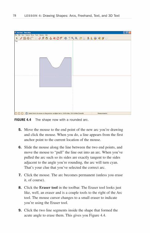
ptg6519239
78 LESSON 4: Drawing Shapes: Arcs, Freehand, Text, and 3D Text
FIGURE 4.4 The shape now with a rounded arc.
5. Move the mouse to the end point of the new arc you’re drawingand click the mouse. When you do, a line appears from the firstanchor point to the current location of the mouse.
6. Slide the mouse along the line between the two end points, andmove the mouse to “pull” the line out into an arc. When you’vepulled the arc such so its sides are exactly tangent to the sidesadjacent to the angle you’re rounding, the arc will turn cyan.That’s your clue that you’ve selected the correct arc.
7. Click the mouse. The arc becomes permanent (unless you eraseit, of course).
8. Click the Eraser tool in the toolbar. The Eraser tool looks justlike, well, an eraser and is a couple tools to the right of the Arctool. The mouse cursor changes to a small eraser to indicateyou’re using the Eraser tool.
9. Click the two line segments inside the shape that formed theacute angle to erase them. This gives you Figure 4.4.
Wow! eBook <WoweBook.Com>
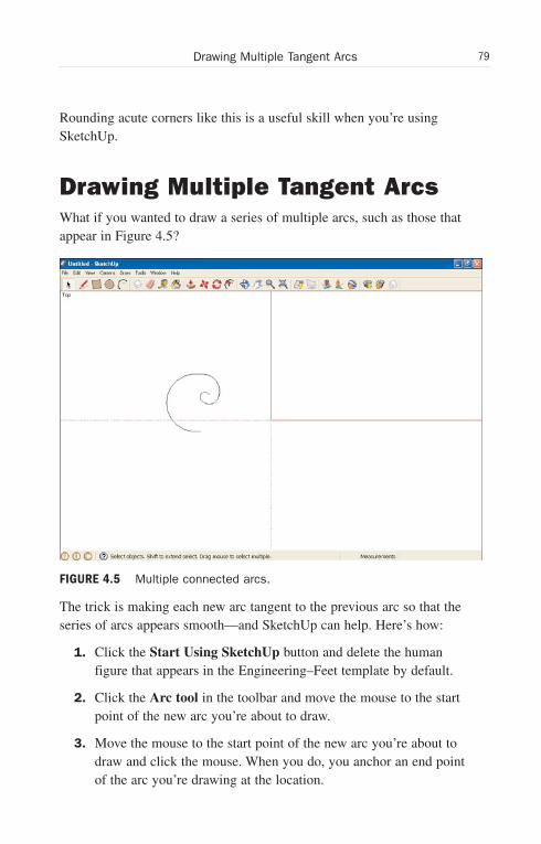
ptg6519239
79Drawing Multiple Tangent Arcs
Rounding acute corners like this is a useful skill when you’re usingSketchUp.
Drawing Multiple Tangent ArcsWhat if you wanted to draw a series of multiple arcs, such as those thatappear in Figure 4.5?
The trick is making each new arc tangent to the previous arc so that theseries of arcs appears smooth—and SketchUp can help. Here’s how:
1. Click the Start Using SketchUp button and delete the humanfigure that appears in the Engineering–Feet template by default.
2. Click the Arc tool in the toolbar and move the mouse to the startpoint of the new arc you’re about to draw.
3. Move the mouse to the start point of the new arc you’re about todraw and click the mouse. When you do, you anchor an end pointof the arc you’re drawing at the location.
FIGURE 4.5 Multiple connected arcs.
Wow! eBook <WoweBook.Com>
ptg6519239
80 LESSON 4: Drawing Shapes: Arcs, Freehand, Text, and 3D Text
4. Move the mouse to the end point of the new arc you’re drawingand click the mouse. When you do, a line appears from the firstanchor point to the current location of the mouse.
5. Slide the mouse along the line between the two end points, andmove the mouse to “pull” the line out into an arc and click themouse. The arc becomes permanent (unless you erase it, ofcourse).
6. Click the end point of the arc you want to continue and move themouse away from the end point. As you do, SketchUp will drawa new arc in blue tangent to the old arc.
7. Move the mouse to the new arc’s end point and click the mouse.The new arc becomes permanent.
8. Repeat steps 6 and 7 for additional arcs.
That’s it—now you can draw all kinds of fancy spirals.
Setting the Number of ArcSegmentsBy default, arcs have twelve sides, but you can change that to any numberof sides you want. Here’s how:
1. Click the Start Using SketchUp button and click the human fig-ure that appears in the Engineering–Feet template to select it;press the Del key to delete it.
2. Click the Arc tool in the toolbar (shown previously in Figure 4.1).
3. Move the mouse to the start point of the new arc you’re about todraw and click the mouse. When you do, you anchor an end pointof the arc you’re drawing at that location.
4. Move the mouse to the end point of the new arc you’re drawingand click the mouse. When you do, a line appears from the firstanchor point to the current location of the mouse.
Wow! eBook <WoweBook.Com>

ptg6519239
81Setting the Number of Arc Segments
5. Slide the mouse along the line between the two end points, andmove the mouse to “pull” the line out into an arc. When you do,an arc appears from the first anchor point to the current locationof the mouse.
6. Type the number of sides you want, followed by “s.” For exam-ple, 5s will give you a five-sided arc.
7. Press Enter. The arc changes to have the number of sides you’verequested.
8. Continue pulling the arc into position.
9. Click the mouse. The arc becomes permanent. Figure 4.6 shows afive-sided arc.
And now you can draw arcs with as many sides as you want.
FIGURE 4.6 A five-sided arc.
Wow! eBook <WoweBook.Com>
ptg6519239
82 LESSON 4: Drawing Shapes: Arcs, Freehand, Text, and 3D Text
Drawing FreehandDrawing freehand couldn’t be easier in one sense—you just drag themouse; but it also couldn’t be harder in another—if you want to draw fig-ures with any accuracy, it’s extraordinarily difficult to do so with themouse.
NOTE: You’re Not Actually Drawing Freehand
If you were actually drawing entirely freehand, each location of themouse would appear as a dot as you moved over it. But becausethere are only a limited number of mouse events per second,SketchUp draws the mouse locations it gets and then connects thedots with line segments. So if you draw very rapidly, your figuresmight end up looking more like interconnected lines.
Here’s how to use the freehand tool:
1. Click the Start Using SketchUp button and click the human fig-ure that appears in the Engineering–Feet template to select it;press the Del key to delete it.
2. Select the View, Toolbars, Large Tool Set menu item. This willopen the large toolset toolbar.
3. Click the Freehand tool in the large toolbar (as shown inFigure 4.7).
4. Move the mouse to the location you want to start drawing from.
5. Press the mouse button and drag the mouse to draw the figureyou want. SketchUp draws the figure following the mouse.
You can see an example in Figure 4.7.
Note that you can’t “fix” a freehand drawing on the pixel level inSketchUp—the only practical thing is to start over.
Wow! eBook <WoweBook.Com>

ptg6519239
83Drawing Surfaces Freehand
The Freehand Tool
FIGURE 4.7 Drawing freehand with the Freehand tool.
Drawing Surfaces FreehandIn addition to freehand figures of the kind you see in Figure 4.7, you canalso draw complete surfaces in SketchUp. After you complete a surface,SketchUp will color it in automatically.
Essentially, you draw freehand figures as detailed in the previous task withan additional step: Close the figure you’re drawing. When you close thefigure, SketchUp can treat it as a completed surface and fills it in. You cansee a few surfaces drawn freehand in Figure 4.8.
Note that it’s quite difficult to draw accurate surfaces freehand, and thatyou usually draw elaborate surfaces as conglomerations of simpler sur-faces from the toolbar.
Wow! eBook <WoweBook.Com>
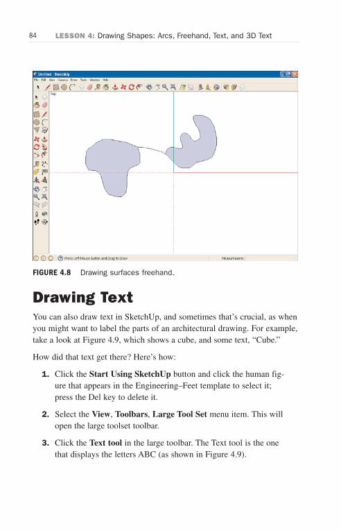
ptg6519239
84 LESSON 4: Drawing Shapes: Arcs, Freehand, Text, and 3D Text
FIGURE 4.8 Drawing surfaces freehand.
Drawing TextYou can also draw text in SketchUp, and sometimes that’s crucial, as whenyou might want to label the parts of an architectural drawing. For example,take a look at Figure 4.9, which shows a cube, and some text, “Cube.”
How did that text get there? Here’s how:
1. Click the Start Using SketchUp button and click the human fig-ure that appears in the Engineering–Feet template to select it;press the Del key to delete it.
2. Select the View, Toolbars, Large Tool Set menu item. This willopen the large toolset toolbar.
3. Click the Text tool in the large toolbar. The Text tool is the onethat displays the letters ABC (as shown in Figure 4.9).
Wow! eBook <WoweBook.Com>
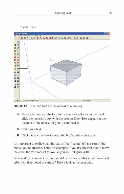
ptg6519239
85Drawing Text
The Text Tool
FIGURE 4.9 The Text tool and some text in a drawing.
4. Move the mouse to the location you want to place your text andclick the mouse. A box with the prompt Enter Text appears at thelocation of the mouse for you to enter text in.
5. Enter your text.
6. Click outside the box to make the box’s outline disappear.
It’s important to realize that this text is free-floating; it’s not part of themodel you’re drawing. Thus, for example, if you use the Pan tool to movethe cube, the text doesn’t follow, as you see in Figure 4.10.
So how do you connect text to a model or surface so that it will move andorbit with that model or surface? Take a look at the next task.
Wow! eBook <WoweBook.Com>
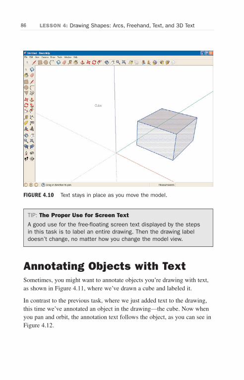
ptg6519239
86 LESSON 4: Drawing Shapes: Arcs, Freehand, Text, and 3D Text
FIGURE 4.10 Text stays in place as you move the model.
TIP: The Proper Use for Screen Text
A good use for the free-floating screen text displayed by the stepsin this task is to label an entire drawing. Then the drawing labeldoesn’t change, no matter how you change the model view.
Annotating Objects with TextSometimes, you might want to annotate objects you’re drawing with text,as shown in Figure 4.11, where we’ve drawn a cube and labeled it.
In contrast to the previous task, where we just added text to the drawing,this time we’ve annotated an object in the drawing—the cube. Now whenyou pan and orbit, the annotation text follows the object, as you can see inFigure 4.12.
Wow! eBook <WoweBook.Com>

ptg6519239
87Annotating Objects with Text
FIGURE 4.11 Annotation text for a model.
FIGURE 4.12 Annotation text follows a model.
Wow! eBook <WoweBook.Com>
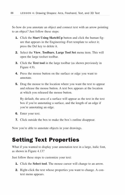
ptg6519239
88 LESSON 4: Drawing Shapes: Arcs, Freehand, Text, and 3D Text
So how do you annotate an object and connect text with an arrow pointingto an object? Just follow these steps:
1. Click the Start Using SketchUp button and click the human fig-ure that appears in the Engineering–Feet template to select it;press the Del key to delete it.
2. Select the View, Toolbars, Large Tool Set menu item. This willopen the large toolset toolbar.
3. Click the Text tool in the large toolbar (as shown previously inFigure 4.9).
4. Press the mouse button on the surface or edge you want toannotate.
5. Drag the mouse to the location where you want the text to appearand release the mouse button. A text box appears at the locationat which you released the mouse button.
By default, the area of a surface will appear as the text in the textbox if you’re annotating a surface, and the length of an edge ifyou’re annotating an edge.
6. Enter your text.
7. Click outside the box to make the box’s outline disappear.
Now you’re able to annotate objects in your drawings.
Setting Text PropertiesWhat if you wanted to display your annotation text in a large, italic font,as shown in Figure 4.13?
Just follow these steps to customize your text:
1. Click the Select tool. The mouse cursor will change to an arrow.
2. Right-click the text whose properties you want to change. A con-text menu appears.
Wow! eBook <WoweBook.Com>
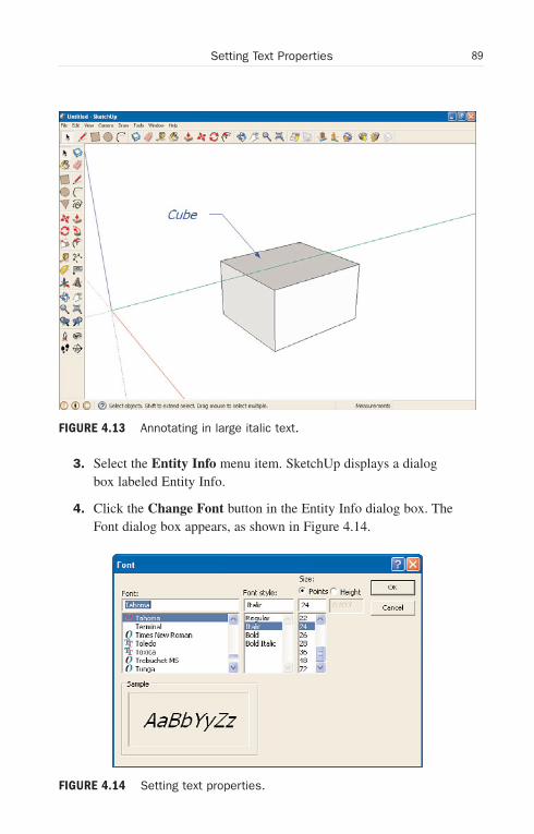
ptg6519239
89Setting Text Properties
FIGURE 4.13 Annotating in large italic text.
3. Select the Entity Info menu item. SketchUp displays a dialogbox labeled Entity Info.
4. Click the Change Font button in the Entity Info dialog box. TheFont dialog box appears, as shown in Figure 4.14.
FIGURE 4.14 Setting text properties.
Wow! eBook <WoweBook.Com>
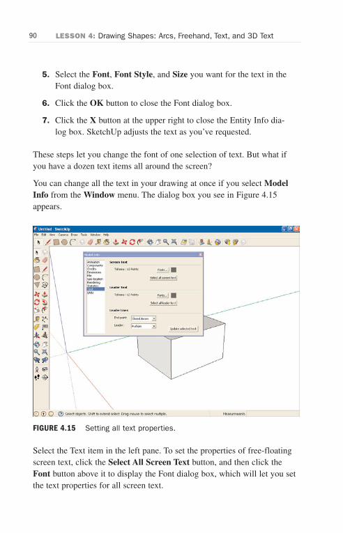
ptg6519239
90 LESSON 4: Drawing Shapes: Arcs, Freehand, Text, and 3D Text
5. Select the Font, Font Style, and Size you want for the text in theFont dialog box.
6. Click the OK button to close the Font dialog box.
7. Click the X button at the upper right to close the Entity Info dia-log box. SketchUp adjusts the text as you’ve requested.
These steps let you change the font of one selection of text. But what ifyou have a dozen text items all around the screen?
You can change all the text in your drawing at once if you select ModelInfo from the Window menu. The dialog box you see in Figure 4.15appears.
Select the Text item in the left pane. To set the properties of free-floatingscreen text, click the Select All Screen Text button, and then click theFont button above it to display the Font dialog box, which will let you setthe text properties for all screen text.
FIGURE 4.15 Setting all text properties.
Wow! eBook <WoweBook.Com>
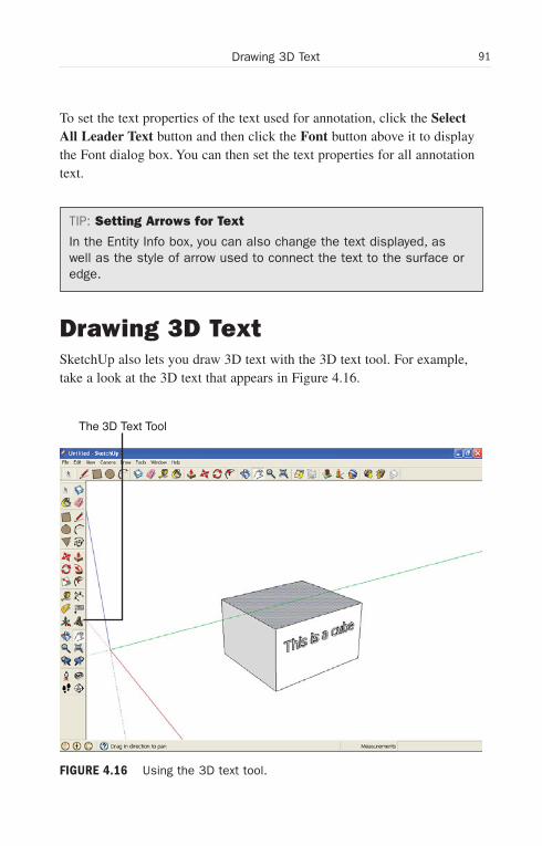
ptg6519239
91Drawing 3D Text
To set the text properties of the text used for annotation, click the SelectAll Leader Text button and then click the Font button above it to displaythe Font dialog box. You can then set the text properties for all annotationtext.
TIP: Setting Arrows for Text
In the Entity Info box, you can also change the text displayed, aswell as the style of arrow used to connect the text to the surface oredge.
Drawing 3D TextSketchUp also lets you draw 3D text with the 3D text tool. For example,take a look at the 3D text that appears in Figure 4.16.
The 3D Text Tool
FIGURE 4.16 Using the 3D text tool.
Wow! eBook <WoweBook.Com>
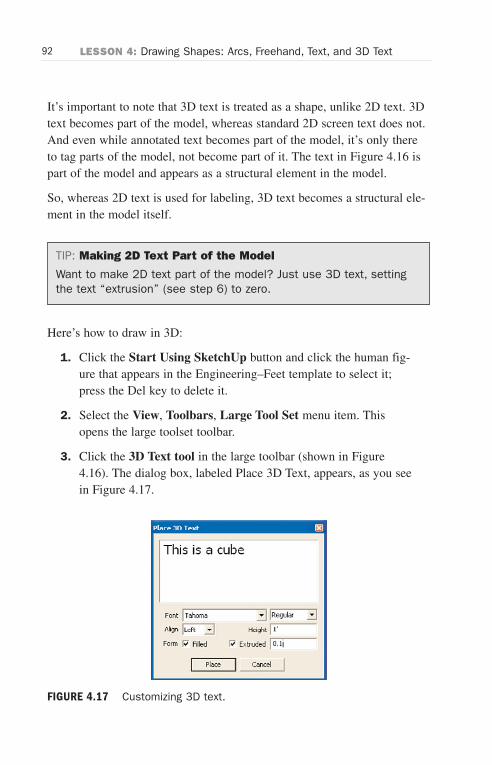
ptg6519239
92 LESSON 4: Drawing Shapes: Arcs, Freehand, Text, and 3D Text
It’s important to note that 3D text is treated as a shape, unlike 2D text. 3Dtext becomes part of the model, whereas standard 2D screen text does not.And even while annotated text becomes part of the model, it’s only thereto tag parts of the model, not become part of it. The text in Figure 4.16 ispart of the model and appears as a structural element in the model.
So, whereas 2D text is used for labeling, 3D text becomes a structural ele-ment in the model itself.
TIP: Making 2D Text Part of the Model
Want to make 2D text part of the model? Just use 3D text, settingthe text “extrusion” (see step 6) to zero.
Here’s how to draw in 3D:
1. Click the Start Using SketchUp button and click the human fig-ure that appears in the Engineering–Feet template to select it;press the Del key to delete it.
2. Select the View, Toolbars, Large Tool Set menu item. Thisopens the large toolset toolbar.
3. Click the 3D Text tool in the large toolbar (shown in Figure4.16). The dialog box, labeled Place 3D Text, appears, as you seein Figure 4.17.
FIGURE 4.17 Customizing 3D text.
Wow! eBook <WoweBook.Com>
ptg6519239
93Drawing 3D Text
4. Enter the text you want to make 3D in the large text box.
5. Select the Font, Alignment, Text style (Regular or Bold), andwhether you want the characters to appear filled in.
6. Enter the height of the characters you want (using ' for feet, " forinches, m for meters, or cm for centimeters) in the Height boxand the 3D depth you want to give to the characters in theExtruded box.
7. Click the Place button. The dialog box disappears, and the textappears as a model element that is selected and that moves as themouse moves.
8. Move the mouse to move the text and then click the mouse toplace the text in the model. The text will align to any axis or sur-face, just as any other model element.
That’s it—you can now add 3D text to models using the 3D Text tool.
Wow! eBook <WoweBook.Com>

ptg6519239
This page intentionally left blank
Wow! eBook <WoweBook.Com>

ptg6519239
LESSON 5
Going 3D
In this lesson, we’re going to see what SketchUp is really all about—going 3D.
Getting StartedSketchUp’s 3D capabilities are what set it apart from the rest of the packof drawing tools. You’re going to see how easy it is to create 3D models inSketchUp. Although you might think that you need to draw every edge tomake a model 3D, that’s not true—SketchUp operates in a very clever wayto give you 3D power.
All you need to do is to draw a 2D surface (and remember, such surfacescan be aligned to any plane). Then you use one of SketchUp’s 3D tools,such as the Push/Pull tool, to pull it into 3D. Thus a rectangle becomes acube, for example.
The Push/Pull tool, which works on any surface that’s in one plane, is theprimary 3D tool in SketchUp. This tool lets you push or pull surfaces into3D in a way that’s quite impressive. But other tools in SketchUp have 3Dpower as well, such as the Move tool, which we’ll also see here.
You can use the Move tool to move objects around, of course. But whenyou first use the Select tool to select an edge, you can use the Move tool topull out that edge in such a way that the connected surface follows, whilestill being anchored on the opposite edge (think of opening a cabinetdoor).
We’ll see both the Push/Pull and Move tools in this lesson, along withsome auxiliary tools, the Select tool and the Eraser tool.
Wow! eBook <WoweBook.Com>
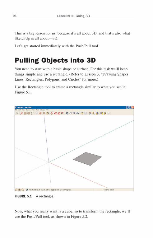
ptg6519239
96 LESSON 5: Going 3D
FIGURE 5.1 A rectangle.
This is a big lesson for us, because it’s all about 3D, and that’s also whatSketchUp is all about—3D.
Let’s get started immediately with the Push/Pull tool.
Pulling Objects into 3DYou need to start with a basic shape or surface. For this task we’ll keepthings simple and use a rectangle. (Refer to Lesson 3, “Drawing Shapes:Lines, Rectangles, Polygons, and Circles” for more.)
Use the Rectangle tool to create a rectangle similar to what you see inFigure 5.1.
Now, what you really want is a cube, so to transform the rectangle, we’lluse the Push/Pull tool, as shown in Figure 5.2.
Wow! eBook <WoweBook.Com>

ptg6519239
97Pulling Objects into 3D
The Push/Pull Tool
FIGURE 5.2 The Push/Pull tool and the resulting cube.
When you use the Push/Pull tool (shown in Figure 5.2), you literally pullthe rectangle into a 3D shape. This tool is at the center of what SketchUpdoes for you, so it’s an important one to learn.
Here’s how to go 3D with SketchUp and the Push/Pull tool:
1. Click the Start Using SketchUp button and click the human fig-ure that appears in the Engineering–Feet template to select it;press the Del key to delete it.
2. Draw a shape.
3. Click the Push/Pull tool in the toolbar (shown in Figure 5.2).
4. Move the mouse cursor to the surface you want to pull or pushinto 3D. Note that the surface must be flat.
5. Press the mouse button on the surface and drag the surface in thedirection you want to extend it into 3D.
Wow! eBook <WoweBook.Com>

ptg6519239
98 LESSON 5: Going 3D
TIP: Pushing or Pulling Surfaces
Note that you can only push or pull surfaces perpendicular to themselves.
As you drag the mouse, the surface pulls into 3D. The sides ofthe new 3D shape are defined by the edges of the 2D shape.
6. Release the mouse button. The object becomes 3D, as you cansee in Figure 5.2. As you can see, pulling shapes into 3D is onethe coolest features in SketchUp.
Pushing Objects into 3DIn the previous task, you saw that you could pull a free-standing rectangleinto 3D. But now take a look at Figure 5.3.
Can you pull the attached circle into a cylinder? Yes, you can. In fact, nowyou have two options. Because the circle is attached to an existing 3D
FIGURE 5.3 A cube with an attached circle.
Wow! eBook <WoweBook.Com>
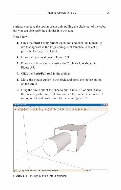
ptg6519239
99Pushing Objects into 3D
surface, you have the option of not only pulling the circle out of the cube,but you can also push the cylinder into the cube.
Here’s how:
1. Click the Start Using SketchUp button and click the human fig-ure that appears in the Engineering–Feet template to select it;press the Del key to delete it.
2. Draw the cube as shown in Figure 5.3.
3. Draw a circle on the cube using the Circle tool, as shown inFigure 5.3.
4. Click the Push/Pull tool in the toolbar.
5. Move the mouse cursor to the circle and press the mouse buttonon the circle.
6. Drag the circle out of the cube to pull it into 3D, or push it intothe cube to push it into 3D. You can see the circle pulled into 3Din Figure 5.4 and pushed into the cube in Figure 5.5.
FIGURE 5.4 Pulling a circle into a cylinder.
Wow! eBook <WoweBook.Com>

ptg6519239
100 LESSON 5: Going 3D
7. Release the mouse button. The cylinder becomes 3D.
Now you can both pull and push objects into 3D.
Using Measured Push/PullWhat if you wanted to push or pull an object exactly 5 feet when making it3D? That is, suppose you have a circle on one surface of a cube (refer toFigure 5.3), and you want to pull the circle out into a cylinder exactly 5feet—could you do it?
Yes. Like most SketchUp operations, you can interrupt them midway andenter a measurement. Here’s how it works when you’re pushing orpulling objects into 3D—in this example, we’ll pull a cylinder out of acube by 5 feet:
1. Click the Start Using SketchUp button and click the human fig-ure that appears in the Engineering–Feet template to select it;press the Del key to delete it.
FIGURE 5.5 Pushing a cylinder into a cube.
Wow! eBook <WoweBook.Com>
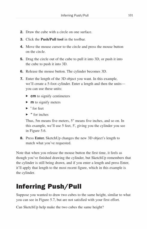
ptg6519239
101Inferring Push/Pull
2. Draw the cube with a circle on one surface.
3. Click the Push/Pull tool in the toolbar.
4. Move the mouse cursor to the circle and press the mouse buttonon the circle.
5. Drag the circle out of the cube to pull it into 3D, or push it intothe cube to push it into 3D.
6. Release the mouse button. The cylinder becomes 3D.
7. Enter the length of the 3D object you want. In this example,we’ll create a 5-foot cylinder. Enter a length and then the units—you can use these units:
. cm to signify centimeters
. m to signify meters
. ' for feet
. " for inches
Thus, 5m means five meters, 5" means five inches, and so on. Inthis example, we’ll use 5 feet, 5', giving you the cylinder you seein Figure 5.6.
8. Press Enter. SketchUp changes the new 3D object’s length tomatch what you’ve requested.
Note that when you release the mouse button the first time, it feels asthough you’ve finished drawing the cylinder, but SketchUp remembers thatthe cylinder is still being drawn, and if you enter a length and press Enter,it’ll apply that length to the most recent figure, which in this example isthe cylinder.
Inferring Push/PullSuppose you wanted to draw two cubes to the same height, similar to whatyou can see in Figure 5.7, but are not satisfied with your first effort.
Can SketchUp help make the two cubes the same height?
Wow! eBook <WoweBook.Com>

ptg6519239
102 LESSON 5: Going 3D
FIGURE 5.6 A measured cylinder.
FIGURE 5.7 Two cubes.
Wow! eBook <WoweBook.Com>
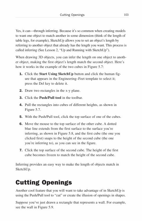
ptg6519239
103Cutting Openings
Yes, it can—through inferring. Because it’s so common when creating modelsto want one object to match another in some dimension (think of the length oftable legs, for example), SketchUp allows you to set an object’s length byreferring to another object that already has the length you want. This process iscalled inferring (See Lesson 2, “Up and Running with SketchUp”).
When drawing 3D objects, you can infer the length on one object to anoth-er object, making the first object’s length match the second object. Here’show it works in the example of the two cubes in Figure 5.7:
1. Click the Start Using SketchUp button and click the human fig-ure that appears in the Engineering–Feet template to select it;press the Del key to delete it.
2. Draw two rectangles in the x-y plane.
3. Click the Push/Pull tool in the toolbar.
4. Pull the rectangles into cubes of different heights, as shown inFigure 5.7.
5. With the Push/Pull tool, click the top surface of one of the cubes.
6. Move the mouse to the top surface of the other cube. A dottedblue line extends from the first surface to the surface you’reinferring, as shown in Figure 5.8, and the first cube (the one youclicked first) snaps to the height of the second cube (the oneyou’re inferring to), as you can see in the figure.
7. Click the top surface of the second cube. The height of the firstcube becomes frozen to match the height of the second cube.
Inferring provides an easy way to make the length of objects match inSketchUp.
Cutting OpeningsAnother cool feature that you will want to take advantage of in SketchUp isusing the Push/Pull tool to “cut” or create the illusion of openings in shapes.
Suppose you’ve just drawn a rectangle that represents a wall. For example,see the wall in Figure 5.9.
Wow! eBook <WoweBook.Com>
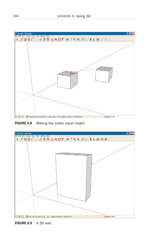
ptg6519239
104 LESSON 5: Going 3D
FIGURE 5.8 Making the cubes equal height.
FIGURE 5.9 A 3D wall.
Wow! eBook <WoweBook.Com>
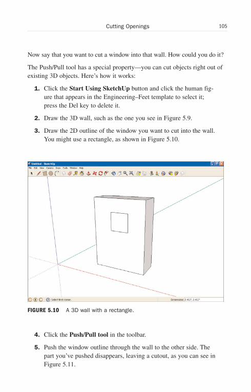
ptg6519239
105Cutting Openings
Now say that you want to cut a window into that wall. How could you do it?
The Push/Pull tool has a special property—you can cut objects right out ofexisting 3D objects. Here’s how it works:
1. Click the Start Using SketchUp button and click the human fig-ure that appears in the Engineering–Feet template to select it;press the Del key to delete it.
2. Draw the 3D wall, such as the one you see in Figure 5.9.
3. Draw the 2D outline of the window you want to cut into the wall.You might use a rectangle, as shown in Figure 5.10.
4. Click the Push/Pull tool in the toolbar.
5. Push the window outline through the wall to the other side. Thepart you’ve pushed disappears, leaving a cutout, as you can see inFigure 5.11.
FIGURE 5.10 A 3D wall with a rectangle.
Wow! eBook <WoweBook.Com>
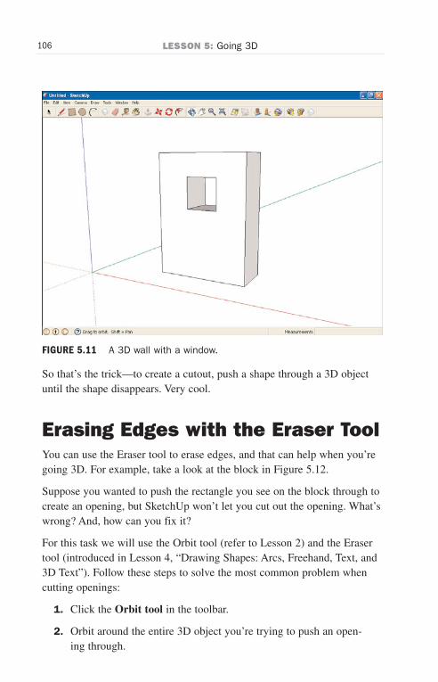
ptg6519239
106 LESSON 5: Going 3D
So that’s the trick—to create a cutout, push a shape through a 3D objectuntil the shape disappears. Very cool.
Erasing Edges with the Eraser ToolYou can use the Eraser tool to erase edges, and that can help when you’regoing 3D. For example, take a look at the block in Figure 5.12.
Suppose you wanted to push the rectangle you see on the block through tocreate an opening, but SketchUp won’t let you cut out the opening. What’swrong? And, how can you fix it?
For this task we will use the Orbit tool (refer to Lesson 2) and the Erasertool (introduced in Lesson 4, “Drawing Shapes: Arcs, Freehand, Text, and3D Text”). Follow these steps to solve the most common problem whencutting openings:
1. Click the Orbit tool in the toolbar.
2. Orbit around the entire 3D object you’re trying to push an open-ing through.
FIGURE 5.11 A 3D wall with a window.
Wow! eBook <WoweBook.Com>

ptg6519239
107Erasing Edges with the Eraser Tool
FIGURE 5.12 A 3D block with rectangle.
3. Search for obstructing edges—SketchUp won’t push openingsthrough edges. In the case of the object in Figure 5.12, it turnsout that there’s an edge drawn across the back of the object, asyou can see in Figure 5.13. This edge will stop SketchUp frompushing an opening through the object.
4. To get rid of unwanted edges, select the Eraser tool in the toolbar.
TIP: The Eraser Tool Is Only to Erase Edges
In SketchUp, you use the Eraser tool only to erase edges. But ifyou want to get rid of a surface, it’s easy—just erase all its edges.
5. Click the unwanted edge. When you do, that edge disappears.
6. Push the rectangle through the object to the other side with thePush/Pull tool. The part you’ve pushed disappears, leaving acutout, as you can see in Figure 5.14.
So that’s the way you use the Eraser tool—to erase unwanted edges. Andif you want to get rid of a surface, erase its edges.
Wow! eBook <WoweBook.Com>
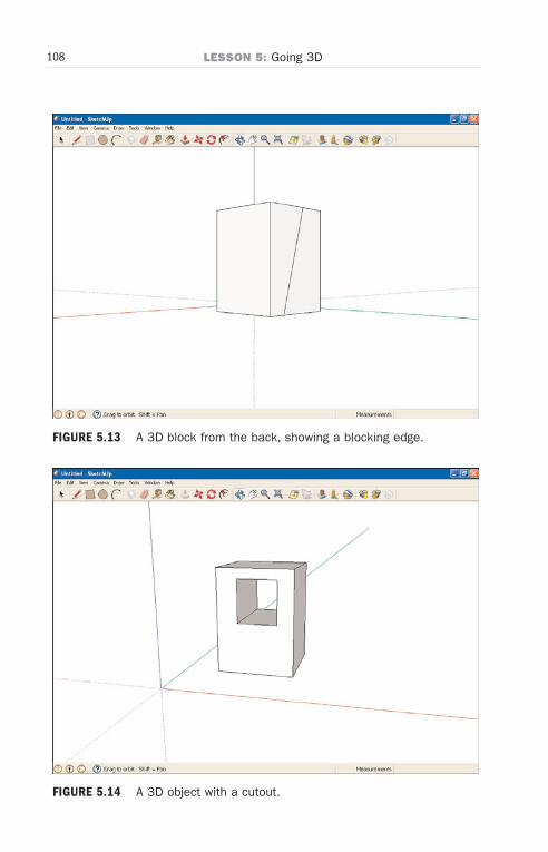
ptg6519239
108 LESSON 5: Going 3D
FIGURE 5.13 A 3D block from the back, showing a blocking edge.
FIGURE 5.14 A 3D object with a cutout.
Wow! eBook <WoweBook.Com>
ptg6519239
109Selecting Edges and Surfaces with the Select Tool
Selecting Edges and Surfaceswith the Select ToolNow that you’ve mastered drawing surfaces and are working with 3Dobjects, it’s time to see how to select edges, surfaces, and objects using theSelect tool.
Knowing how to select edges, surfaces, and objects is important for manyactions in SketchUp, because you often have to indicate to SketchUp justwhat item you’re working with. For example, when you want to make acopy of an object, you start by selecting that object. Selecting an objectbrings it to SketchUp’s attention by telling it just what item you’re work-ing with. When you want to use the Move tool to pull out an edge from anobject into 3D, you start by selecting that edge.
When you select an object, SketchUp indicates your selection by drawingit in a slightly different color than it was before, or by making it appeardotted. After you’ve selected an item, you can use that item as the target ofyour following operations, as we’ll see. For example, if you had threeboxes and wanted to make copies of only one, you’d start by selecting thebox you want to make copies of, and then the appropriate menu choices tocopy the item, as we’re going to see in this lesson.
Selecting surfaces and edges is easy. Just click the Select tool in theGetting Started toolbar (recall the Select tool has an arrow as its icon, andis the first tool on the left in the Getting Started toolbar), and click the sur-face or edge you want to select.
When you select a surface, SketchUp fills the surface with blue dots.When you select an edge, SketchUp colors it blue.
Selecting an entire object is also easy, because the Select tool lets youdraw selection rectangles automatically. Just press the mouse button out-side the object and drag the mouse over the object to draw a selection rec-tangle, as you see in Figure 5.15.
When you release the mouse button, the entire object will be selected (andyou can use menu selections to copy it, move it, and so on), which meansall its surfaces will be dotted in blue, and its edges will be drawn in blue.
Wow! eBook <WoweBook.Com>
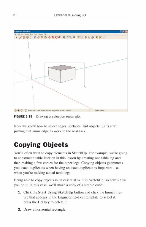
ptg6519239
110 LESSON 5: Going 3D
FIGURE 5.15 Drawing a selection rectangle.
Now we know how to select edges, surfaces, and objects. Let’s startputting that knowledge to work in the next task.
Copying ObjectsYou’ll often want to copy elements in SketchUp. For example, we’re goingto construct a table later on in this lesson by creating one table leg andthen making a few copies for the other legs. Copying objects guaranteesyou exact duplicates when having an exact duplicate is important—aswhen you’re making actual table legs.
Being able to copy objects is an essential skill in SketchUp, so here’s howyou do it. In this case, we’ll make a copy of a simple cube:
1. Click the Start Using SketchUp button and click the human fig-ure that appears in the Engineering–Feet template to select it;press the Del key to delete it.
2. Draw a horizontal rectangle.
Wow! eBook <WoweBook.Com>
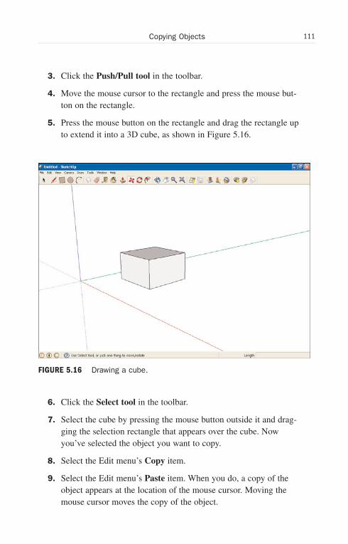
ptg6519239
111Copying Objects
3. Click the Push/Pull tool in the toolbar.
4. Move the mouse cursor to the rectangle and press the mouse but-ton on the rectangle.
5. Press the mouse button on the rectangle and drag the rectangle upto extend it into a 3D cube, as shown in Figure 5.16.
6. Click the Select tool in the toolbar.
7. Select the cube by pressing the mouse button outside it and drag-ging the selection rectangle that appears over the cube. Nowyou’ve selected the object you want to copy.
8. Select the Edit menu’s Copy item.
9. Select the Edit menu’s Paste item. When you do, a copy of theobject appears at the location of the mouse cursor. Moving themouse cursor moves the copy of the object.
FIGURE 5.16 Drawing a cube.
Wow! eBook <WoweBook.Com>
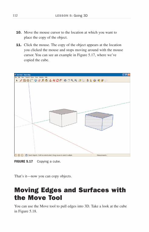
ptg6519239
112 LESSON 5: Going 3D
10. Move the mouse cursor to the location at which you want toplace the copy of the object.
11. Click the mouse. The copy of the object appears at the locationyou clicked the mouse and stops moving around with the mousecursor. You can see an example in Figure 5.17, where we’vecopied the cube.
That’s it—now you can copy objects.
Moving Edges and Surfaces withthe Move ToolYou can use the Move tool to pull edges into 3D. Take a look at the cubein Figure 5.18.
FIGURE 5.17 Copying a cube.
Wow! eBook <WoweBook.Com>
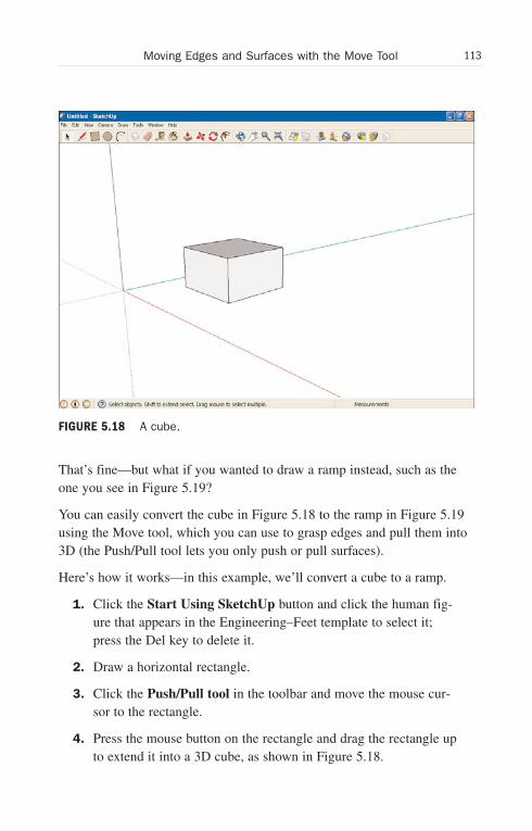
ptg6519239
113Moving Edges and Surfaces with the Move Tool
That’s fine—but what if you wanted to draw a ramp instead, such as theone you see in Figure 5.19?
You can easily convert the cube in Figure 5.18 to the ramp in Figure 5.19using the Move tool, which you can use to grasp edges and pull them into3D (the Push/Pull tool lets you only push or pull surfaces).
Here’s how it works—in this example, we’ll convert a cube to a ramp.
1. Click the Start Using SketchUp button and click the human fig-ure that appears in the Engineering–Feet template to select it;press the Del key to delete it.
2. Draw a horizontal rectangle.
3. Click the Push/Pull tool in the toolbar and move the mouse cur-sor to the rectangle.
4. Press the mouse button on the rectangle and drag the rectangle upto extend it into a 3D cube, as shown in Figure 5.18.
FIGURE 5.18 A cube.
Wow! eBook <WoweBook.Com>
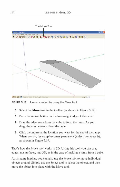
ptg6519239
114 LESSON 5: Going 3D
The Move Tool
FIGURE 5.19 A ramp created by using the Move tool.
5. Select the Move tool in the toolbar (as shown in Figure 5.19).
6. Press the mouse button on the lower-right edge of the cube.
7. Drag the edge away from the cube to form the ramp. As youdrag, the ramp extends from the cube.
8. Click the mouse at the location you want for the end of the ramp.When you do, the ramp becomes permanent (unless you erase it),as shown in Figure 5.19.
That’s how the Move tool works in 3D. Using this tool, you can dragedges, not surfaces, into 3D, as in the case of making a ramp from a cube.
As its name implies, you can also use the Move tool to move individualobjects around. Simply use the Select tool to select the object, and thenmove the object into place with the Move tool.
Wow! eBook <WoweBook.Com>
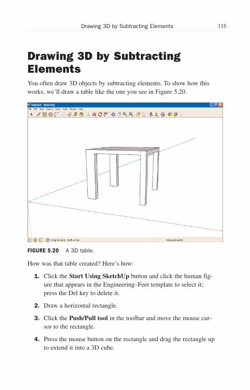
ptg6519239
115Drawing 3D by Subtracting Elements
Drawing 3D by SubtractingElementsYou often draw 3D objects by subtracting elements. To show how thisworks, we’ll draw a table like the one you see in Figure 5.20.
How was that table created? Here’s how:
1. Click the Start Using SketchUp button and click the human fig-ure that appears in the Engineering–Feet template to select it;press the Del key to delete it.
2. Draw a horizontal rectangle.
3. Click the Push/Pull tool in the toolbar and move the mouse cur-sor to the rectangle.
4. Press the mouse button on the rectangle and drag the rectangle upto extend it into a 3D cube.
FIGURE 5.20 A 3D table.
Wow! eBook <WoweBook.Com>

ptg6519239
116 LESSON 5: Going 3D
5. Select the Rectangle tool in the toolbar.
6. Draw a rectangle on the cube as shown in Figure 5.21.
7. Select the Push/Pull tool in the toolbar.
8. Push the rectangle through the cube until you get a cutout in theshape of the rectangle.
9. Select the Rectangle tool in the toolbar.
10. Draw a rectangle on a cube surface adjacent to the first surfacewhere you drew a rectangle. Draw the rectangle so that pushing itthrough will give you two of the table’s legs.
11. Select the Push/Pull tool in the toolbar.
12. Push the rectangle through until you get a cutout in the shapeof the rectangle. You can see what the result will look like inFigure 5.22.
FIGURE 5.21 Adding a rectangle to a cube.
Wow! eBook <WoweBook.Com>

ptg6519239
117Drawing 3D by Subtracting Elements
13. Select the Rectangle tool in the toolbar.
14. Draw a rectangle on the remaining vertical cube surface. Drawthe rectangle so that pushing it through will give you the finaltwo table legs.
15. Select the Push/Pull tool in the toolbar.
16. Push the rectangle through until you get a cutout in the shape ofthe rectangle. That creates the table in Figure 5.20.
And that’s one technique for drawing 3D—by subtracting elements.
TIP: Making the Table Legs Identical
If you want to make sure the table legs are identical in all dimen-sions, you can use inferring. Select the Move tool, hover over thesurface of a leg, then click another leg’s corresponding surface tosnap to the corresponding measurement.
FIGURE 5.22 Pushing through a rectangle.
Wow! eBook <WoweBook.Com>

ptg6519239
This page intentionally left blank
Wow! eBook <WoweBook.Com>

ptg6519239
LESSON 6
Creating Componentsand Groups
In this lesson, we’re going to take the shapes we’ve been drawing in theprevious lessons and start assembling them into groups and components tolet us handle them all together.
Getting StartedFor example, suppose that you’ve been drawing a car with all the surfacesyou need for that. But then you find when you want to move or copy androtate or even enlarge the model, you have to select all the surfaces indi-vidually to handle them all together.
Wouldn’t it be easier to have SketchUp understand that it’s supposed totreat all the surfaces of the car as a collection, handling all actions on allsurfaces in the collection at once?
That’s what groups and components are all about, and you’ll find yourselfusing both of these as you progress in SketchUp. When you take shapesand/or objects and collect them into a group or component, you can thenhandle the collection of shapes as one object, copying it all at once, ormoving, rotating it, and so on.
Many of the tools in SketchUp behave differently when you’re workingwith a group or component than when you’re just working with aEngineering–Feet shape, so we’ll also discuss how that works in this lesson.
Wow! eBook <WoweBook.Com>
ptg6519239
120 LESSON 6: Creating Components and Groups
NOTE: What’s the Difference Between Groups andComponents?
It has to do with the fact that when you edit one component, allcopies of the component are edited as well, but that’s not true ofgroups.
Let’s get started immediately by seeing how SketchUp handles multipleobjects by default.
Using Sticky GeometryWe’ll start this lesson with a discussion of the rudimentary way thatSketchUp handles collections of objects by default—using a system calledsticky geometry.
NOTE: On the Use of Tools
It’s assumed in these tasks that you have been progressingthrough each lesson in order and learning about the individual toolsreferenced here. If you need to flip back for review, check outLesson 3, “Drawing Shapes: Lines, Rectangles, Polygons, andCircles,” for more on the Rectangle and Circle tools. And seeLesson 5, “Going 3D,” for refreshers on the Push/Pull and Movetools.
When you bring two objects next to each other, they can “adhere” andbecome one object. It’s sort of a rudimentary form of creating groups inSketchUp. Because sticky geometry is part of SketchUp, and because it’sall about connecting objects into one (the topic of this lesson), we’ll take alook at sticky geometry here.
To get an idea of how sticky geometry works, follow these steps:
1. Start SketchUp. For this task, we’ll work with theEngineering–Feet template we’ve used in the previous lessons.
Wow! eBook <WoweBook.Com>
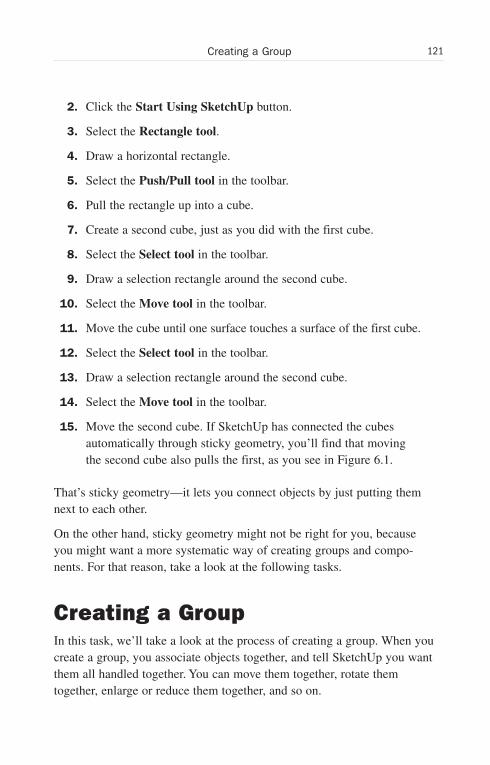
ptg6519239
121Creating a Group
2. Click the Start Using SketchUp button.
3. Select the Rectangle tool.
4. Draw a horizontal rectangle.
5. Select the Push/Pull tool in the toolbar.
6. Pull the rectangle up into a cube.
7. Create a second cube, just as you did with the first cube.
8. Select the Select tool in the toolbar.
9. Draw a selection rectangle around the second cube.
10. Select the Move tool in the toolbar.
11. Move the cube until one surface touches a surface of the first cube.
12. Select the Select tool in the toolbar.
13. Draw a selection rectangle around the second cube.
14. Select the Move tool in the toolbar.
15. Move the second cube. If SketchUp has connected the cubesautomatically through sticky geometry, you’ll find that movingthe second cube also pulls the first, as you see in Figure 6.1.
That’s sticky geometry—it lets you connect objects by just putting themnext to each other.
On the other hand, sticky geometry might not be right for you, becauseyou might want a more systematic way of creating groups and compo-nents. For that reason, take a look at the following tasks.
Creating a GroupIn this task, we’ll take a look at the process of creating a group. When youcreate a group, you associate objects together, and tell SketchUp you wantthem all handled together. You can move them together, rotate themtogether, enlarge or reduce them together, and so on.
Wow! eBook <WoweBook.Com>
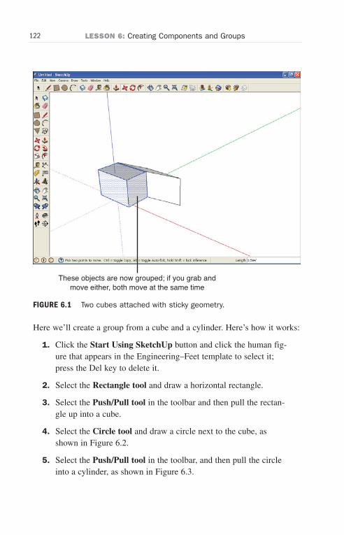
ptg6519239
122 LESSON 6: Creating Components and Groups
These objects are now grouped; if you grab andmove either, both move at the same time
FIGURE 6.1 Two cubes attached with sticky geometry.
Here we’ll create a group from a cube and a cylinder. Here’s how it works:
1. Click the Start Using SketchUp button and click the human fig-ure that appears in the Engineering–Feet template to select it;press the Del key to delete it.
2. Select the Rectangle tool and draw a horizontal rectangle.
3. Select the Push/Pull tool in the toolbar and then pull the rectan-gle up into a cube.
4. Select the Circle tool and draw a circle next to the cube, asshown in Figure 6.2.
5. Select the Push/Pull tool in the toolbar, and then pull the circleinto a cylinder, as shown in Figure 6.3.
Wow! eBook <WoweBook.Com>
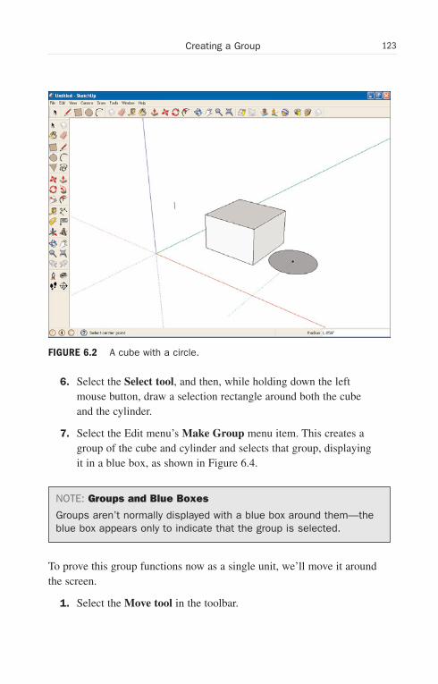
ptg6519239
123Creating a Group
FIGURE 6.2 A cube with a circle.
6. Select the Select tool, and then, while holding down the leftmouse button, draw a selection rectangle around both the cubeand the cylinder.
7. Select the Edit menu’s Make Group menu item. This creates agroup of the cube and cylinder and selects that group, displayingit in a blue box, as shown in Figure 6.4.
NOTE: Groups and Blue Boxes
Groups aren’t normally displayed with a blue box around them—theblue box appears only to indicate that the group is selected.
To prove this group functions now as a single unit, we’ll move it aroundthe screen.
1. Select the Move tool in the toolbar.
Wow! eBook <WoweBook.Com>
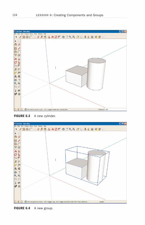
ptg6519239
124 LESSON 6: Creating Components and Groups
FIGURE 6.3 A new cylinder.
FIGURE 6.4 A new group.
Wow! eBook <WoweBook.Com>
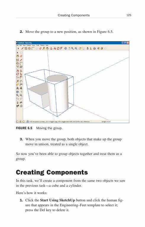
ptg6519239
125Creating Components
2. Move the group to a new position, as shown in Figure 6.5.
3. When you move the group, both objects that make up the groupmove in unison, treated as a single object.
So now you’ve been able to group objects together and treat them as agroup.
Creating ComponentsIn this task, we’ll create a component from the same two objects we sawin the previous task—a cube and a cylinder.
Here’s how it works:
1. Click the Start Using SketchUp button and click the human fig-ure that appears in the Engineering–Feet template to select it;press the Del key to delete it.
FIGURE 6.5 Moving the group.
Wow! eBook <WoweBook.Com>

ptg6519239
126 LESSON 6: Creating Components and Groups
2. Select the Rectangle tool and draw a horizontal rectangle.
3. Select the Push/Pull tool in the toolbar, and then pull the rectan-gle up into a cube.
4. Select the Circle tool and draw a circle next to the cube.
5. Select the Push/Pull tool in the toolbar, and then pull the circleinto a cylinder.
6. Select the Select tool, and then draw a selection rectangle aroundboth the cube and the cylinder.
7. Select the Edit menu’s Make Component menu item. SketchUpdisplays the dialog box you see in Figure 6.6.
8. Enter Cube Cylinder Component in the Name box.
9. Enter A cube with a cylinder in the Description box.
10. Click the Create button. The dialog box disappears and a blueselection box surrounds your new component, exactly as with thegroup in the previous task (refer to Figure 6.4).
To prove this component functions now as a single unit, we’ll move itaround the screen.
FIGURE 6.6 The Create Component dialog box.
Wow! eBook <WoweBook.Com>
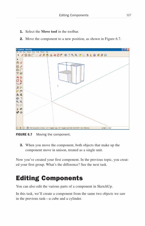
ptg6519239
127Editing Components
1. Select the Move tool in the toolbar.
2. Move the component to a new position, as shown in Figure 6.7.
3. When you move the component, both objects that make up thecomponent move in unison, treated as a single unit.
Now you’ve created your first component. In the previous topic, you creat-ed your first group. What’s the difference? See the next task.
Editing ComponentsYou can also edit the various parts of a component in SketchUp.
In this task, we’ll create a component from the same two objects we sawin the previous task—a cube and a cylinder.
FIGURE 6.7 Moving the component.
Wow! eBook <WoweBook.Com>
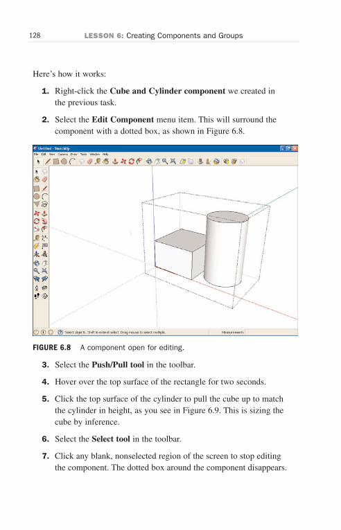
ptg6519239
128 LESSON 6: Creating Components and Groups
Here’s how it works:
1. Right-click the Cube and Cylinder component we created inthe previous task.
2. Select the Edit Component menu item. This will surround thecomponent with a dotted box, as shown in Figure 6.8.
3. Select the Push/Pull tool in the toolbar.
4. Hover over the top surface of the rectangle for two seconds.
5. Click the top surface of the cylinder to pull the cube up to matchthe cylinder in height, as you see in Figure 6.9. This is sizing thecube by inference.
6. Select the Select tool in the toolbar.
7. Click any blank, nonselected region of the screen to stop editingthe component. The dotted box around the component disappears.
FIGURE 6.8 A component open for editing.
Wow! eBook <WoweBook.Com>
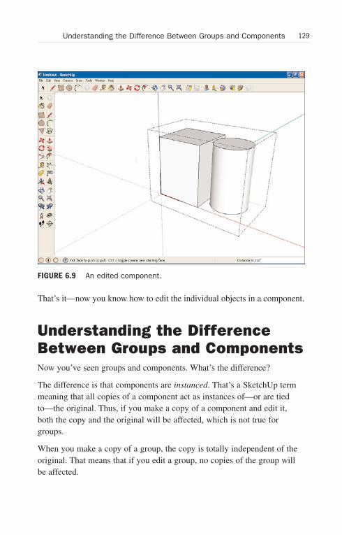
ptg6519239
129Understanding the Difference Between Groups and Components
FIGURE 6.9 An edited component.
That’s it—now you know how to edit the individual objects in a component.
Understanding the DifferenceBetween Groups and ComponentsNow you’ve seen groups and components. What’s the difference?
The difference is that components are instanced. That’s a SketchUp termmeaning that all copies of a component act as instances of—or are tiedto—the original. Thus, if you make a copy of a component and edit it,both the copy and the original will be affected, which is not true forgroups.
When you make a copy of a group, the copy is totally independent of theoriginal. That means that if you edit a group, no copies of the group willbe affected.
Wow! eBook <WoweBook.Com>
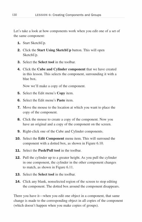
ptg6519239
130 LESSON 6: Creating Components and Groups
Let’s take a look at how components work when you edit one of a set ofthe same component:
1. Start SketchUp.
2. Click the Start Using SketchUp button. This will openSketchUp.
3. Select the Select tool in the toolbar.
4. Click the Cube and Cylinder component that we have createdin this lesson. This selects the component, surrounding it with ablue box.
Now we’ll make a copy of the component.
5. Select the Edit menu’s Copy item.
6. Select the Edit menu’s Paste item.
7. Move the mouse to the location at which you want to place thecopy of the component.
8. Click the mouse to create a copy of the component. Now youhave an original and a copy of the component on the screen.
9. Right-click one of the Cube and Cylinder components.
10. Select the Edit Component menu item. This will surround thecomponent with a dotted box, as shown in Figure 6.10.
11. Select the Push/Pull tool in the toolbar.
12. Pull the cylinder up to a greater height. As you pull the cylinderin one component, the cylinder in the other component changesto match, as shown in Figure 6.11.
13. Select the Select tool in the toolbar.
14. Click any blank, nonselected region of the screen to stop editingthe component. The dotted box around the component disappears.
There you have it—when you edit one object in a component, that samechange is made to the corresponding object in all copies of the component(which doesn’t happen when you make copies of groups).
Wow! eBook <WoweBook.Com>
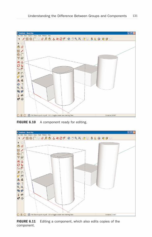
ptg6519239
131Understanding the Difference Between Groups and Components
FIGURE 6.10 A component ready for editing.
FIGURE 6.11 Editing a component, which also edits copies of the component.
Wow! eBook <WoweBook.Com>
ptg6519239
132 LESSON 6: Creating Components and Groups
Exploding a ComponentHaving created a component, can you de-create it? That is, can you“explode” the objects in the component so that they no longer make up acomponent?
Yes, you can. Just follow these steps to create a component and thenexplode it back into its parts:
1. Click the Start Using SketchUp button and click the human fig-ure that appears in the Engineering–Feet template to select it;press the Del key to delete it.
2. Select the Rectangle tool and draw a horizontal rectangle.
3. Select the Push/Pull tool in the toolbar, and then pull the rectan-gle up into a cube.
4. Select the Circle tool and draw a circle next to the cube.
5. Select the Push/Pull tool in the toolbar, and then pull the circleinto a cylinder.
6. Select the Select tool, and then draw a selection rectangle aroundboth the cube and the cylinder.
7. Select the Edit menu’s Make Component item. SketchUp dis-plays a dialog box.
8. Enter Two Cubes Component in the Name box.
9. Enter Two cubes in the Description box.
10. Click the Create button. The dialog box disappears.
A blue selection box surrounds your new component—you’vecreated your component.
The next step is to explode it back into two separate cubes.
11. While your component is selected (has a blue box around it),right-click the component. A context menu appears.
12. Select Explode from the context menu. The blue selection boxaround the component disappears, and the two cubes are nolonger one component.
Wow! eBook <WoweBook.Com>
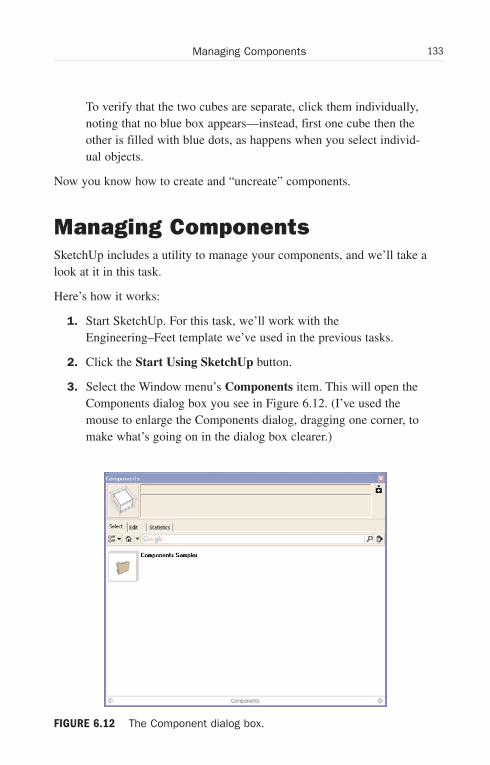
ptg6519239
133Managing Components
To verify that the two cubes are separate, click them individually,noting that no blue box appears—instead, first one cube then theother is filled with blue dots, as happens when you select individ-ual objects.
Now you know how to create and “uncreate” components.
Managing ComponentsSketchUp includes a utility to manage your components, and we’ll take alook at it in this task.
Here’s how it works:
1. Start SketchUp. For this task, we’ll work with theEngineering–Feet template we’ve used in the previous tasks.
2. Click the Start Using SketchUp button.
3. Select the Window menu’s Components item. This will open theComponents dialog box you see in Figure 6.12. (I’ve used themouse to enlarge the Components dialog, dragging one corner, tomake what’s going on in the dialog box clearer.)
FIGURE 6.12 The Component dialog box.
Wow! eBook <WoweBook.Com>
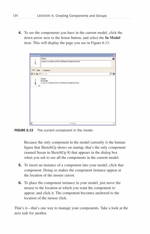
ptg6519239
134 LESSON 6: Creating Components and Groups
4. To see the components you have in the current model, click thedown arrow next to the house button, and select the In Modelitem. This will display the page you see in Figure 6.13.
Because the only component in the model currently is the humanfigure that SketchUp shows on startup, that’s the only component(named Susan in SketchUp 8) that appears in the dialog boxwhen you ask to see all the components in the current model.
5. To insert an instance of a component into your model, click thatcomponent. Doing so makes the component instance appear atthe location of the mouse cursor.
6. To place the component instance in your model, just move themouse to the location at which you want the component toappear, and click it. The component becomes anchored to thelocation of the mouse click.
That’s it—that’s one way to manage your components. Take a look at thenext task for another.
FIGURE 6.13 The current component in the model.
Wow! eBook <WoweBook.Com>
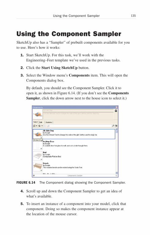
ptg6519239
135Using the Component Sampler
Using the Component SamplerSketchUp also has a “Sampler” of prebuilt components available for youto use. Here’s how it works:
1. Start SketchUp. For this task, we’ll work with theEngineering–Feet template we’ve used in the previous tasks.
2. Click the Start Using SketchUp button.
3. Select the Window menu’s Components item. This will open theComponents dialog box.
By default, you should see the Component Sampler. Click it toopen it, as shown in Figure 6.14. (If you don’t see the ComponentsSampler, click the down arrow next to the house icon to select it.)
4. Scroll up and down the Component Sampler to get an idea ofwhat’s available.
5. To insert an instance of a component into your model, click thatcomponent. Doing so makes the component instance appear atthe location of the mouse cursor.
FIGURE 6.14 The Component dialog showing the Component Sampler.
Wow! eBook <WoweBook.Com>

ptg6519239
136 LESSON 6: Creating Components and Groups
6. To place the component instance in your model, move the mouseto the location at which you want the component to appear, andclick it. The component becomes anchored to the location of themouse click.
Using the 3D WarehouseSketchUp also has available a “warehouse” of components that you canuse and download.
Let’s assume you want to draw a couch. Here’s how it works:
1. Click the Start Using SketchUp button.
2. Select the Window menu’s Components item. This opens theComponents dialog box. By default, you should see theComponent Sampler.
3. Click the down arrow next to the house button. This will displaya drop-down menu of component collections.
The choices for the Component collections are
. Architecture
. Landscape
. Construction
. People
. Playground
. Transportation
For this task, we’ll choose the Architecture collections.
4. Select the Architecture menu item. This will display a dialogbox, as you see in Figure 6.15, of component collections avail-able in Google’s 3D Warehouse.
5. Select the Furniture item. This displays the items in theFurniture collection of Google’s 3D warehouse, as shown inFigure 6.16.
Wow! eBook <WoweBook.Com>

ptg6519239
137Using the 3D Warehouse
FIGURE 6.15 The Architecture component collections.
6. Click the Seating item. This downloads the Seating collectionfrom the 3D warehouse, as shown in Figure 6.17.
FIGURE 6.16 The Furniture component collections.
Wow! eBook <WoweBook.Com>

ptg6519239
138 LESSON 6: Creating Components and Groups
7. Click the Couch Rounded item. Doing so makes the componentinstance appear at the location of the mouse cursor.
8. To place the component instance in your model, move the mouseto the location at which you want the component to appear, andclick it. The component becomes anchored to the location of themouse click, as shown in Figure 6.18.
There are dozens of components ready for you to download and use fromthe 3D warehouse—give it a try.
FIGURE 6.17 The Seating component collections.
Wow! eBook <WoweBook.Com>
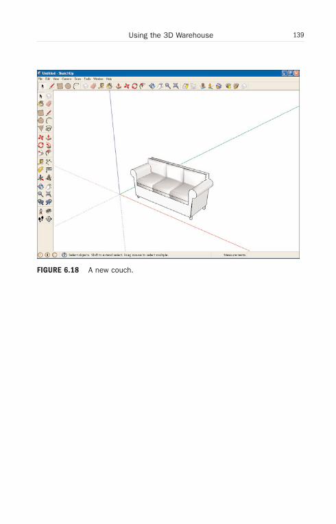
ptg6519239
139Using the 3D Warehouse
FIGURE 6.18 A new couch.
Wow! eBook <WoweBook.Com>

ptg6519239
This page intentionally left blank
Wow! eBook <WoweBook.Com>
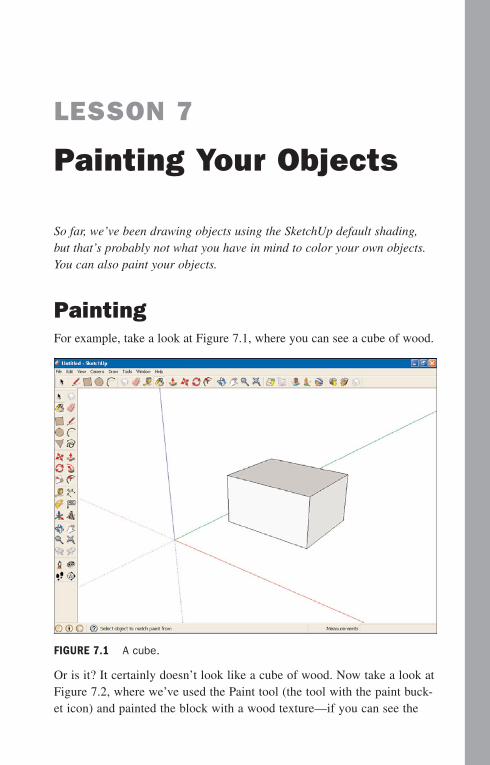
ptg6519239
LESSON 7
Painting Your Objects
So far, we’ve been drawing objects using the SketchUp default shading,but that’s probably not what you have in mind to color your own objects.You can also paint your objects.
PaintingFor example, take a look at Figure 7.1, where you can see a cube of wood.
Or is it? It certainly doesn’t look like a cube of wood. Now take a look atFigure 7.2, where we’ve used the Paint tool (the tool with the paint buck-et icon) and painted the block with a wood texture—if you can see the
FIGURE 7.1 A cube.
Wow! eBook <WoweBook.Com>
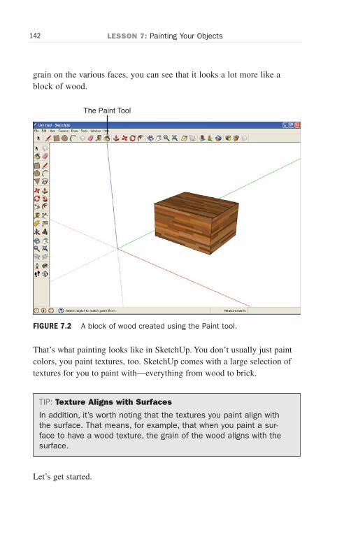
ptg6519239
142 LESSON 7: Painting Your Objects
grain on the various faces, you can see that it looks a lot more like ablock of wood.
That’s what painting looks like in SketchUp. You don’t usually just paintcolors, you paint textures, too. SketchUp comes with a large selection oftextures for you to paint with—everything from wood to brick.
TIP: Texture Aligns with Surfaces
In addition, it’s worth noting that the textures you paint align withthe surface. That means, for example, that when you paint a sur-face to have a wood texture, the grain of the wood aligns with thesurface.
Let’s get started.
The Paint Tool
FIGURE 7.2 A block of wood created using the Paint tool.
Wow! eBook <WoweBook.Com>
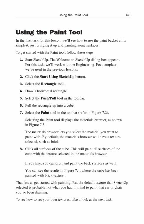
ptg6519239
143Using the Paint Tool
Using the Paint ToolIn the first task for this lesson, we’ll see how to use the paint bucket at itssimplest, just bringing it up and painting some surfaces.
To get started with the Paint tool, follow these steps:
1. Start SketchUp. The Welcome to SketchUp dialog box appears.For this task, we’ll work with the Engineering–Feet templatewe’ve used in the previous lessons.
2. Click the Start Using SketchUp button.
3. Select the Rectangle tool.
4. Draw a horizontal rectangle.
5. Select the Push/Pull tool in the toolbar.
6. Pull the rectangle up into a cube.
7. Select the Paint tool in the toolbar (refer to Figure 7.2).
Selecting the Paint tool displays the materials browser, as shownin Figure 7.3.
The materials browser lets you select the material you want topaint with. By default, the materials browser will have a textureselected, such as brick.
8. Click all surfaces of the cube. This will paint all surfaces of thecube with the texture selected in the materials browser.
If you like, you can orbit and paint the back surfaces as well.
You can see the results in Figure 7.4, where the cube has beenpainted with brick texture.
That lets us get started with painting. But the default texture that SketchUpselected is probably not what you had in mind to paint that car or chairyou’ve been drawing.
To see how to set your own textures, take a look at the next task.
Wow! eBook <WoweBook.Com>
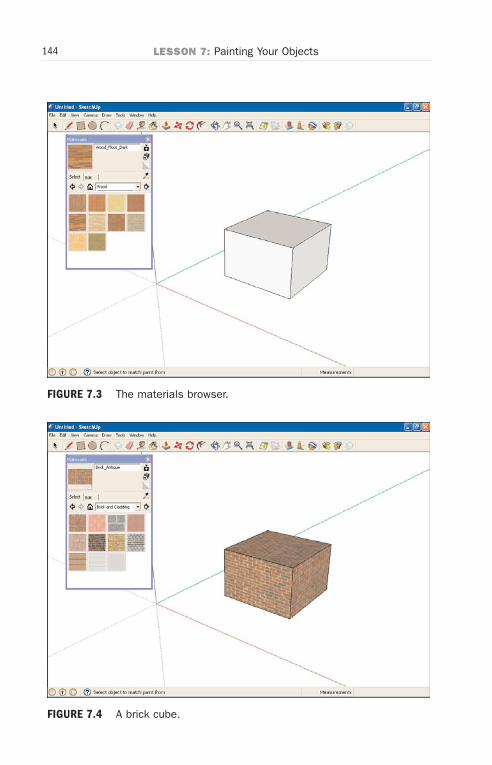
ptg6519239
144 LESSON 7: Painting Your Objects
FIGURE 7.4 A brick cube.
FIGURE 7.3 The materials browser.
Wow! eBook <WoweBook.Com>
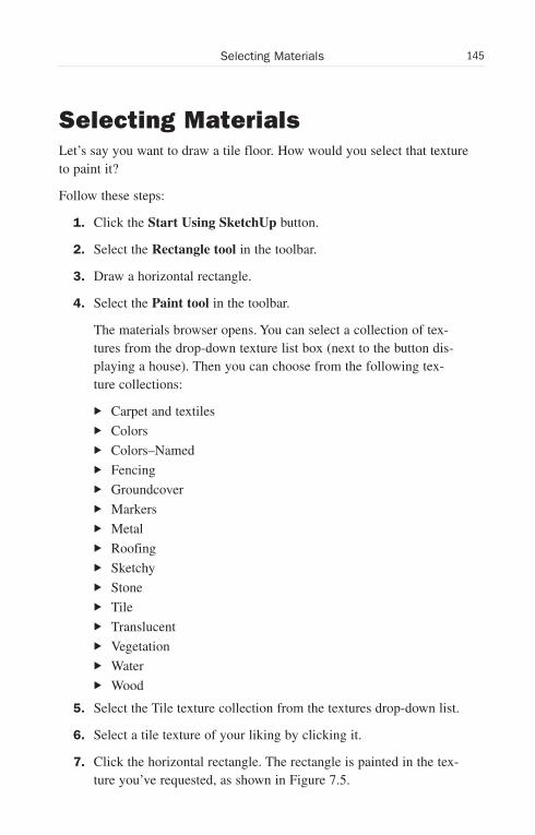
ptg6519239
145Selecting Materials
Selecting MaterialsLet’s say you want to draw a tile floor. How would you select that textureto paint it?
Follow these steps:
1. Click the Start Using SketchUp button.
2. Select the Rectangle tool in the toolbar.
3. Draw a horizontal rectangle.
4. Select the Paint tool in the toolbar.
The materials browser opens. You can select a collection of tex-tures from the drop-down texture list box (next to the button dis-playing a house). Then you can choose from the following tex-ture collections:
. Carpet and textiles
. Colors
. Colors–Named
. Fencing
. Groundcover
. Markers
. Metal
. Roofing
. Sketchy
. Stone
. Tile
. Translucent
. Vegetation
. Water
. Wood
5. Select the Tile texture collection from the textures drop-down list.
6. Select a tile texture of your liking by clicking it.
7. Click the horizontal rectangle. The rectangle is painted in the tex-ture you’ve requested, as shown in Figure 7.5.
Wow! eBook <WoweBook.Com>
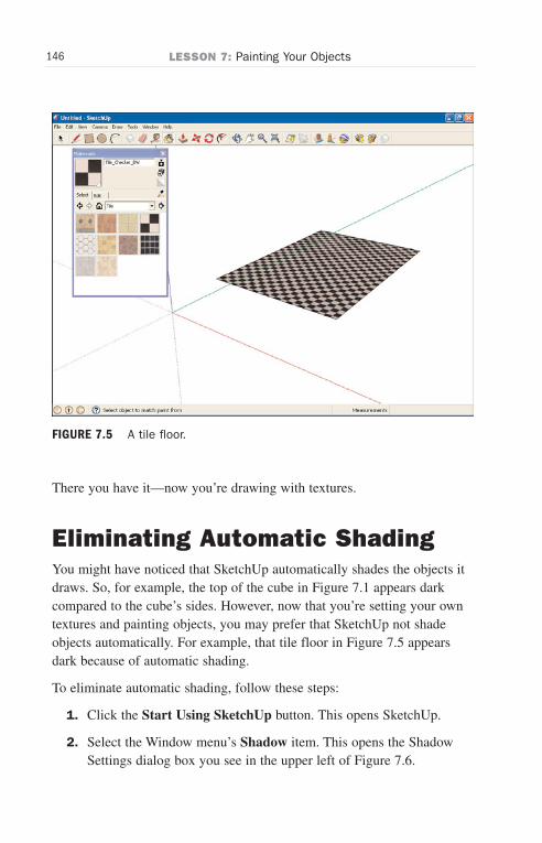
ptg6519239
146 LESSON 7: Painting Your Objects
There you have it—now you’re drawing with textures.
Eliminating Automatic ShadingYou might have noticed that SketchUp automatically shades the objects itdraws. So, for example, the top of the cube in Figure 7.1 appears darkcompared to the cube’s sides. However, now that you’re setting your owntextures and painting objects, you may prefer that SketchUp not shadeobjects automatically. For example, that tile floor in Figure 7.5 appearsdark because of automatic shading.
To eliminate automatic shading, follow these steps:
1. Click the Start Using SketchUp button. This opens SketchUp.
2. Select the Window menu’s Shadow item. This opens the ShadowSettings dialog box you see in the upper left of Figure 7.6.
FIGURE 7.5 A tile floor.
Wow! eBook <WoweBook.Com>
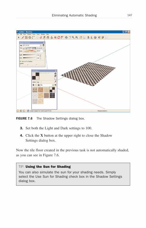
ptg6519239
147Eliminating Automatic Shading
3. Set both the Light and Dark settings to 100.
4. Click the X button at the upper right to close the ShadowSettings dialog box.
Now the tile floor created in the previous task is not automatically shaded,as you can see in Figure 7.6.
TIP: Using the Sun for Shading
You can also simulate the sun for your shading needs. Simplyselect the Use Sun for Shading check box in the Shadow Settingsdialog box.
FIGURE 7.6 The Shadow Settings dialog box.
Wow! eBook <WoweBook.Com>
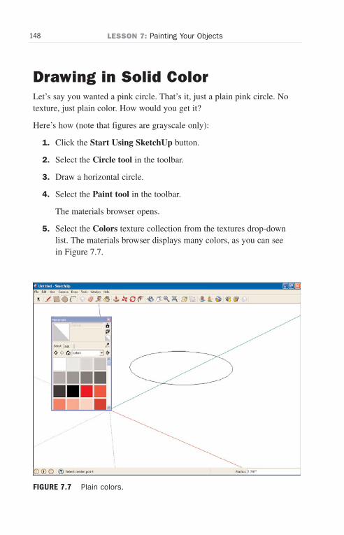
ptg6519239
148 LESSON 7: Painting Your Objects
Drawing in Solid ColorLet’s say you wanted a pink circle. That’s it, just a plain pink circle. Notexture, just plain color. How would you get it?
Here’s how (note that figures are grayscale only):
1. Click the Start Using SketchUp button.
2. Select the Circle tool in the toolbar.
3. Draw a horizontal circle.
4. Select the Paint tool in the toolbar.
The materials browser opens.
5. Select the Colors texture collection from the textures drop-downlist. The materials browser displays many colors, as you can seein Figure 7.7.
FIGURE 7.7 Plain colors.
Wow! eBook <WoweBook.Com>
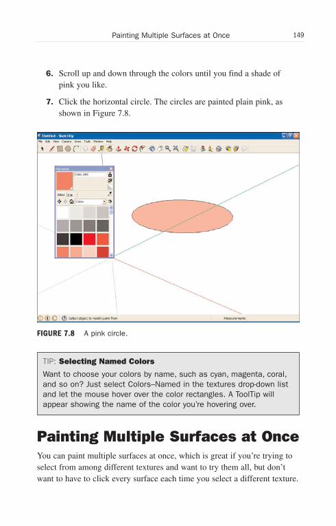
ptg6519239
149Painting Multiple Surfaces at Once
6. Scroll up and down through the colors until you find a shade ofpink you like.
7. Click the horizontal circle. The circles are painted plain pink, asshown in Figure 7.8.
TIP: Selecting Named Colors
Want to choose your colors by name, such as cyan, magenta, coral,and so on? Just select Colors–Named in the textures drop-down listand let the mouse hover over the color rectangles. A ToolTip willappear showing the name of the color you’re hovering over.
Painting Multiple Surfaces at OnceYou can paint multiple surfaces at once, which is great if you’re trying toselect from among different textures and want to try them all, but don’twant to have to click every surface each time you select a different texture.
FIGURE 7.8 A pink circle.
Wow! eBook <WoweBook.Com>
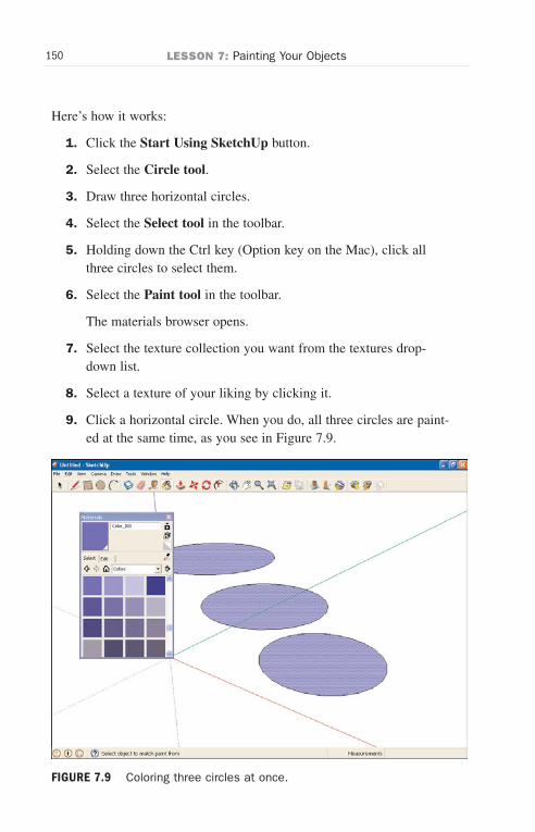
ptg6519239
150 LESSON 7: Painting Your Objects
Here’s how it works:
1. Click the Start Using SketchUp button.
2. Select the Circle tool.
3. Draw three horizontal circles.
4. Select the Select tool in the toolbar.
5. Holding down the Ctrl key (Option key on the Mac), click allthree circles to select them.
6. Select the Paint tool in the toolbar.
The materials browser opens.
7. Select the texture collection you want from the textures drop-down list.
8. Select a texture of your liking by clicking it.
9. Click a horizontal circle. When you do, all three circles are paint-ed at the same time, as you see in Figure 7.9.
FIGURE 7.9 Coloring three circles at once.
Wow! eBook <WoweBook.Com>
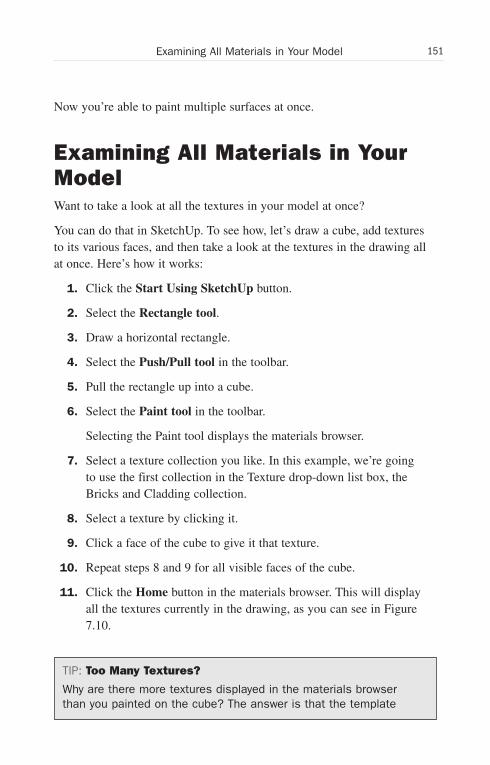
ptg6519239
151Examining All Materials in Your Model
Now you’re able to paint multiple surfaces at once.
Examining All Materials in YourModelWant to take a look at all the textures in your model at once?
You can do that in SketchUp. To see how, let’s draw a cube, add texturesto its various faces, and then take a look at the textures in the drawing allat once. Here’s how it works:
1. Click the Start Using SketchUp button.
2. Select the Rectangle tool.
3. Draw a horizontal rectangle.
4. Select the Push/Pull tool in the toolbar.
5. Pull the rectangle up into a cube.
6. Select the Paint tool in the toolbar.
Selecting the Paint tool displays the materials browser.
7. Select a texture collection you like. In this example, we’re goingto use the first collection in the Texture drop-down list box, theBricks and Cladding collection.
8. Select a texture by clicking it.
9. Click a face of the cube to give it that texture.
10. Repeat steps 8 and 9 for all visible faces of the cube.
11. Click the Home button in the materials browser. This will displayall the textures currently in the drawing, as you can see in Figure7.10.
TIP: Too Many Textures?
Why are there more textures displayed in the materials browserthan you painted on the cube? The answer is that the template
Wow! eBook <WoweBook.Com>
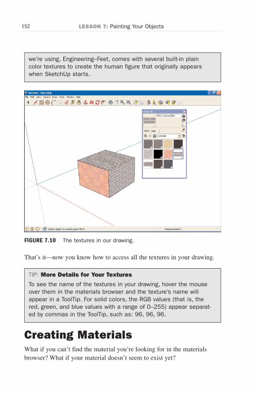
ptg6519239
152 LESSON 7: Painting Your Objects
FIGURE 7.10 The textures in our drawing.
we’re using, Engineering–Feet, comes with several built-in plaincolor textures to create the human figure that originally appearswhen SketchUp starts.
That’s it—now you know how to access all the textures in your drawing.
TIP: More Details for Your Textures
To see the name of the textures in your drawing, hover the mouseover them in the materials browser and the texture’s name willappear in a ToolTip. For solid colors, the RGB values (that is, thered, green, and blue values with a range of 0–255) appear separat-ed by commas in the ToolTip, such as: 96, 96, 96.
Creating MaterialsWhat if you can’t find the material you’re looking for in the materialsbrowser? What if your material doesn’t seem to exist yet?
Wow! eBook <WoweBook.Com>
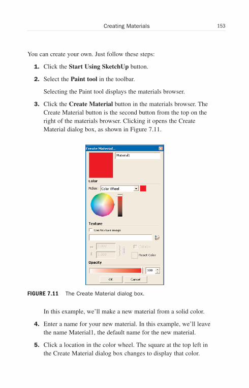
ptg6519239
153Creating Materials
You can create your own. Just follow these steps:
1. Click the Start Using SketchUp button.
2. Select the Paint tool in the toolbar.
Selecting the Paint tool displays the materials browser.
3. Click the Create Material button in the materials browser. TheCreate Material button is the second button from the top on theright of the materials browser. Clicking it opens the CreateMaterial dialog box, as shown in Figure 7.11.
In this example, we’ll make a new material from a solid color.
4. Enter a name for your new material. In this example, we’ll leavethe name Material1, the default name for the new material.
5. Click a location in the color wheel. The square at the top left inthe Create Material dialog box changes to display that color.
FIGURE 7.11 The Create Material dialog box.
Wow! eBook <WoweBook.Com>
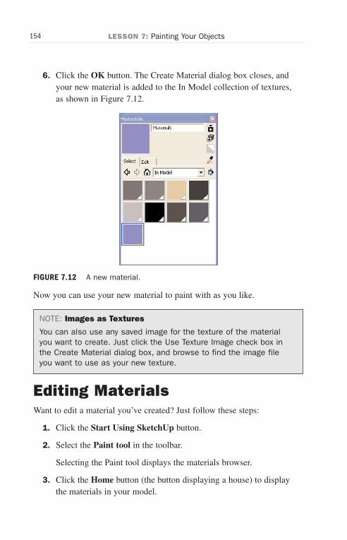
ptg6519239
154 LESSON 7: Painting Your Objects
6. Click the OK button. The Create Material dialog box closes, andyour new material is added to the In Model collection of textures,as shown in Figure 7.12.
Now you can use your new material to paint with as you like.
NOTE: Images as Textures
You can also use any saved image for the texture of the materialyou want to create. Just click the Use Texture Image check box inthe Create Material dialog box, and browse to find the image fileyou want to use as your new texture.
Editing MaterialsWant to edit a material you’ve created? Just follow these steps:
1. Click the Start Using SketchUp button.
2. Select the Paint tool in the toolbar.
Selecting the Paint tool displays the materials browser.
3. Click the Home button (the button displaying a house) to displaythe materials in your model.
FIGURE 7.12 A new material.
Wow! eBook <WoweBook.Com>

ptg6519239
155Editing Materials
4. Select a material by clicking it. This opens the materials in yourmodel, as shown in Figure 7.13.
5. Click a new location in the color wheel, if desired. The square atthe top left in the Create Material dialog box changes to displaythat color.
6. Click the Use Texture Image check box to change the image forthe material’s texture.
7. Browse to the image file that holds the image you want to use fortexture and select it; then click Open in the browsing dialog box.
8. Click the Select tab. The edits you made to your material will besaved automatically.
In this way, you can make any changes to materials.
FIGURE 7.13 Editing a material.
Wow! eBook <WoweBook.Com>
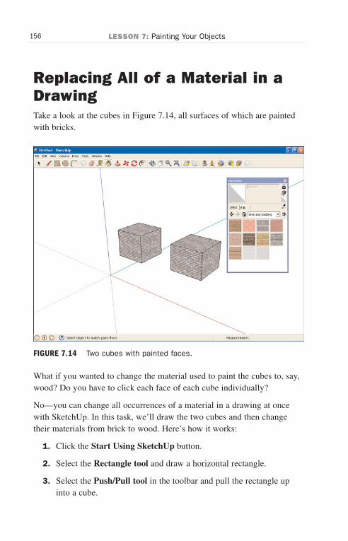
ptg6519239
156 LESSON 7: Painting Your Objects
Replacing All of a Material in aDrawingTake a look at the cubes in Figure 7.14, all surfaces of which are paintedwith bricks.
What if you wanted to change the material used to paint the cubes to, say,wood? Do you have to click each face of each cube individually?
No—you can change all occurrences of a material in a drawing at oncewith SketchUp. In this task, we’ll draw the two cubes and then changetheir materials from brick to wood. Here’s how it works:
1. Click the Start Using SketchUp button.
2. Select the Rectangle tool and draw a horizontal rectangle.
3. Select the Push/Pull tool in the toolbar and pull the rectangle upinto a cube.
FIGURE 7.14 Two cubes with painted faces.
Wow! eBook <WoweBook.Com>
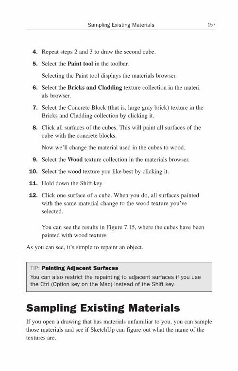
ptg6519239
157Sampling Existing Materials
4. Repeat steps 2 and 3 to draw the second cube.
5. Select the Paint tool in the toolbar.
Selecting the Paint tool displays the materials browser.
6. Select the Bricks and Cladding texture collection in the materi-als browser.
7. Select the Concrete Block (that is, large gray brick) texture in theBricks and Cladding collection by clicking it.
8. Click all surfaces of the cubes. This will paint all surfaces of thecube with the concrete blocks.
Now we’ll change the material used in the cubes to wood.
9. Select the Wood texture collection in the materials browser.
10. Select the wood texture you like best by clicking it.
11. Hold down the Shift key.
12. Click one surface of a cube. When you do, all surfaces paintedwith the same material change to the wood texture you’veselected.
You can see the results in Figure 7.15, where the cubes have beenpainted with wood texture.
As you can see, it’s simple to repaint an object.
TIP: Painting Adjacent Surfaces
You can also restrict the repainting to adjacent surfaces if you usethe Ctrl (Option key on the Mac) instead of the Shift key.
Sampling Existing MaterialsIf you open a drawing that has materials unfamiliar to you, you can samplethose materials and see if SketchUp can figure out what the name of thetextures are.
Wow! eBook <WoweBook.Com>
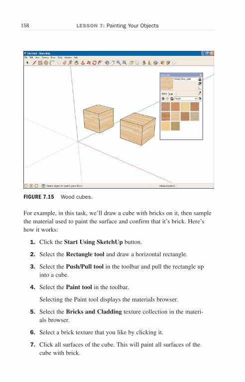
ptg6519239
158 LESSON 7: Painting Your Objects
FIGURE 7.15 Wood cubes.
For example, in this task, we’ll draw a cube with bricks on it, then samplethe material used to paint the surface and confirm that it’s brick. Here’show it works:
1. Click the Start Using SketchUp button.
2. Select the Rectangle tool and draw a horizontal rectangle.
3. Select the Push/Pull tool in the toolbar and pull the rectangle upinto a cube.
4. Select the Paint tool in the toolbar.
Selecting the Paint tool displays the materials browser.
5. Select the Bricks and Cladding texture collection in the materi-als browser.
6. Select a brick texture that you like by clicking it.
7. Click all surfaces of the cube. This will paint all surfaces of thecube with brick.
Wow! eBook <WoweBook.Com>
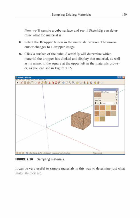
ptg6519239
159Sampling Existing Materials
Now we’ll sample a cube surface and see if SketchUp can deter-mine what the material is.
8. Select the Dropper button in the materials browser. The mousecursor changes to a dropper image.
9. Click a surface of the cube. SketchUp will determine whichmaterial the dropper has clicked and display that material, as wellas its name, in the square at the upper left in the materials brows-er, as you can see in Figure 7.16.
It can be very useful to sample materials in this way to determine just whatmaterials they are.
FIGURE 7.16 Sampling materials.
Wow! eBook <WoweBook.Com>
ptg6519239
160 LESSON 7: Painting Your Objects
Undoing Changes and CancelingOperationsPaint a surface and then wish you hadn’t? SketchUp can undo the change.
In fact, nearly every operation you perform in SketchUp can be undone;from drawing a line to painting a surface, or even deleting an object.
To undo an operation, select the Edit menu’s Undo item. The operationwill be undone and the drawing will be restored to its previous condition.You can also press Ctrl + Z (Option + Z on the Mac) to do the same thing.
What if you’ve started an operation and want to cancel it? For example,suppose you started drawing a line and then changed your mind, but theLine tool is still stretching a line from the point you clicked to the presentmouse location as you move the mouse.
Just press the Esc key. That cancels any operation that you’ve started andgets you out of it.
Wow! eBook <WoweBook.Com>
ptg6519239
LESSON 8
Using the Rotate, Scale,and Follow-Me Tools
In this lesson, we’re going to gain more SketchUp power by manipulatingobjects.
Using Some New ToolsHere, we’ll learn to use the Rotate, Scale, and Follow-Me tools.
. The Rotate tool does just what it sounds like—it rotates objects.You can use this tool not only to rotate whole objects, but alsoparts of objects if you select a part of the object and then fold itacross edges.
. The Scale tool lets you enlarge and reduce objects as you like.This is a useful tool in case you want to make changes to anobject’s size at any time.
. The Follow-Me tool lets you move 2D shapes along paths you’vespecified to create 3D shapes. It’s very cool to watch.
Let’s get started with the Rotate tool.
Rotating ObjectsThe Rotate tool lets you rotate whole objects, or just part of an object.
The Rotate tool first establishes a plane of rotation by orienting itself tothe planes formed by the red, blue, and green axes, or any surface youhover over. Then you establish an axis of rotation and rotate the object.
Wow! eBook <WoweBook.Com>
ptg6519239
162 LESSON 8: Using the Rotate, Scale, and Follow-Me Tools
First, we’ll need an object to rotate. We’ll use the Components dialog (aswe did in Lesson 6, “Creating Components and Groups”) and bring forth aworkstation desk set and orient it the way we want. For this task (and oth-ers in this lesson), we’ll work with the familiar Engineering–Feet template.
Here’s how we can rotate a drawing of a workstation:
1. Start SketchUp.
2. Click the Start Using SketchUp button.
3. Select the Window menu’s Components item.
4. Click the down arrow next to the House button and click theArchitecture component collection.
5. In the Architecture collection, click the Furniture collection.
6. In the Furniture collection, click the Desks collection.
7. Click the Work Station Desk Set component.
8. Click inside your drawing to draw the desk set, as shown inFigure 8.1. Now we’ll rotate the desk set.
9. Select the Rotate tool in the toolbar (shown in Figure 8.1).Selecting the Rotate tool displays a rotation base, which appearsas a double circle, at the location of the mouse cursor. As youmove the mouse, SketchUp aligns the rotation base with theunderlying surfaces.
10. Click the location under the desk around which you want torotate the desk. This anchors the rotation base and sets the loca-tion around which you will rotate the object. You can think of therotation base as an axle hub for the rotation.
NOTE: The Blue Box Indicates What Will Be Rotated
Note that because of the proximity of the rotation base and thedesk, SketchUp surrounds the desk in a blue box to indicate that ithas been selected as the target of your rotation operations.
Wow! eBook <WoweBook.Com>
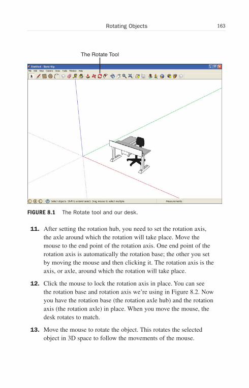
ptg6519239
163Rotating Objects
The Rotate Tool
FIGURE 8.1 The Rotate tool and our desk.
11. After setting the rotation hub, you need to set the rotation axis,the axle around which the rotation will take place. Move themouse to the end point of the rotation axis. One end point of therotation axis is automatically the rotation base; the other you setby moving the mouse and then clicking it. The rotation axis is theaxis, or axle, around which the rotation will take place.
12. Click the mouse to lock the rotation axis in place. You can seethe rotation base and rotation axis we’re using in Figure 8.2. Nowyou have the rotation base (the rotation axle hub) and the rotationaxis (the rotation axle) in place. When you move the mouse, thedesk rotates to match.
13. Move the mouse to rotate the object. This rotates the selectedobject in 3D space to follow the movements of the mouse.
Wow! eBook <WoweBook.Com>

ptg6519239
164 LESSON 8: Using the Rotate, Scale, and Follow-Me Tools
FIGURE 8.2 A rotation base and rotation axis.
14. Click the mouse to lock the object in its rotated position. You cansee the new position of the desk in our example in Figure 8.3.
That’s how rotation works in SketchUp.
Rotating Parts of ObjectsThe Rotate tool lets you rotate part of an object as well, which is greatwhen you want to “fold” part of an object over.
For example, we’ll rotate just part of a cube.
Here’s how it works:
1. Click the Start Using SketchUp button.
2. Select the Rectangle tool and draw a horizontal rectangle.
Wow! eBook <WoweBook.Com>
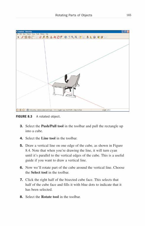
ptg6519239
165Rotating Parts of Objects
FIGURE 8.3 A rotated object.
3. Select the Push/Pull tool in the toolbar and pull the rectangle upinto a cube.
4. Select the Line tool in the toolbar.
5. Draw a vertical line on one edge of the cube, as shown in Figure8.4. Note that when you’re drawing the line, it will turn cyanuntil it’s parallel to the vertical edges of the cube. This is a usefulguide if you want to draw a vertical line.
6. Now we’ll rotate part of the cube around the vertical line. Choosethe Select tool in the toolbar.
7. Click the right half of the bisected cube face. This selects thathalf of the cube face and fills it with blue dots to indicate that ithas been selected.
8. Select the Rotate tool in the toolbar.
Wow! eBook <WoweBook.Com>

ptg6519239
166 LESSON 8: Using the Rotate, Scale, and Follow-Me Tools
FIGURE 8.4 A cube with a line.
9. Click the location under the cube around which you want torotate the selected part of the cube. That is, click directly underthe bottom end point of the bisecting line.
10. After setting the rotation hub, you need to set the rotation axis,the axle around which the rotation will take place. Move themouse to the end point of the rotation axis. That is, move themouse directly above the top end point of the bisecting line.
NOTE: One End Becomes the Rotation Axis
One end point of the rotation axis is automatically the rotationbase; the other you set by moving the mouse and then clicking it.The rotation axis is the axis, or axle, around which the rotation willtake place.
11. Click the mouse to lock the rotation axis in place. Now you havethe rotation base (the rotation axle hub) and the rotation axis (the
Wow! eBook <WoweBook.Com>
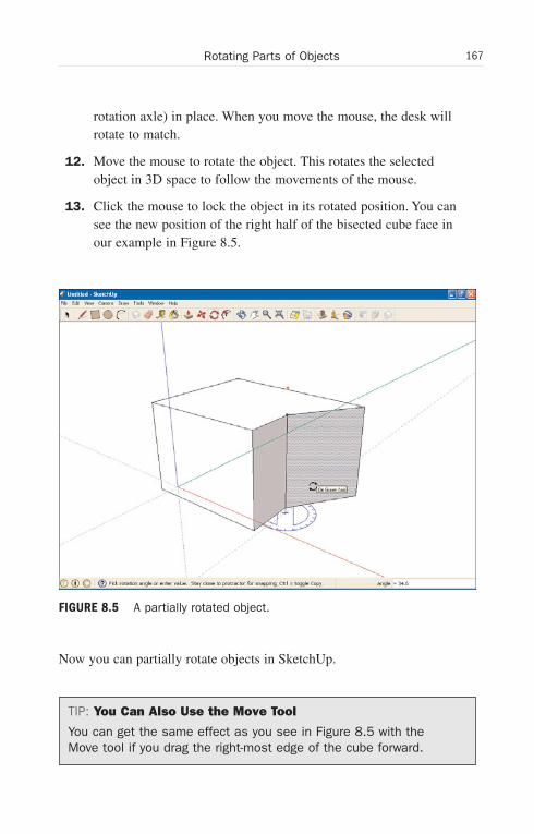
ptg6519239
167Rotating Parts of Objects
rotation axle) in place. When you move the mouse, the desk willrotate to match.
12. Move the mouse to rotate the object. This rotates the selectedobject in 3D space to follow the movements of the mouse.
13. Click the mouse to lock the object in its rotated position. You cansee the new position of the right half of the bisected cube face inour example in Figure 8.5.
Now you can partially rotate objects in SketchUp.
TIP: You Can Also Use the Move Tool
You can get the same effect as you see in Figure 8.5 with theMove tool if you drag the right-most edge of the cube forward.
FIGURE 8.5 A partially rotated object.
Wow! eBook <WoweBook.Com>
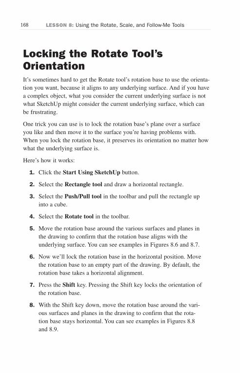
ptg6519239
168 LESSON 8: Using the Rotate, Scale, and Follow-Me Tools
Locking the Rotate Tool’sOrientationIt’s sometimes hard to get the Rotate tool’s rotation base to use the orienta-tion you want, because it aligns to any underlying surface. And if you havea complex object, what you consider the current underlying surface is notwhat SketchUp might consider the current underlying surface, which canbe frustrating.
One trick you can use is to lock the rotation base’s plane over a surfaceyou like and then move it to the surface you’re having problems with.When you lock the rotation base, it preserves its orientation no matter howwhat the underlying surface is.
Here’s how it works:
1. Click the Start Using SketchUp button.
2. Select the Rectangle tool and draw a horizontal rectangle.
3. Select the Push/Pull tool in the toolbar and pull the rectangle upinto a cube.
4. Select the Rotate tool in the toolbar.
5. Move the rotation base around the various surfaces and planes inthe drawing to confirm that the rotation base aligns with theunderlying surface. You can see examples in Figures 8.6 and 8.7.
6. Now we’ll lock the rotation base in the horizontal position. Movethe rotation base to an empty part of the drawing. By default, therotation base takes a horizontal alignment.
7. Press the Shift key. Pressing the Shift key locks the orientation ofthe rotation base.
8. With the Shift key down, move the rotation base around the vari-ous surfaces and planes in the drawing to confirm that the rota-tion base stays horizontal. You can see examples in Figures 8.8and 8.9.
Wow! eBook <WoweBook.Com>
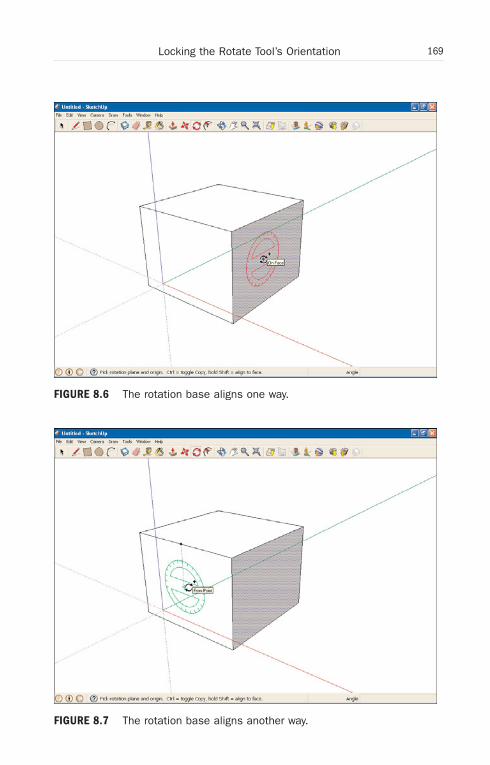
ptg6519239
169Locking the Rotate Tool’s Orientation
FIGURE 8.6 The rotation base aligns one way.
FIGURE 8.7 The rotation base aligns another way.
Wow! eBook <WoweBook.Com>
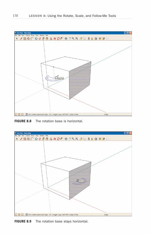
ptg6519239
170 LESSON 8: Using the Rotate, Scale, and Follow-Me Tools
FIGURE 8.8 The rotation base is horizontal.
FIGURE 8.9 The rotation base stays horizontal.
Wow! eBook <WoweBook.Com>
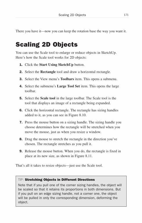
ptg6519239
171Scaling 2D Objects
There you have it—now you can keep the rotation base the way you want it.
Scaling 2D ObjectsYou can use the Scale tool to enlarge or reduce objects in SketchUp.Here’s how the Scale tool works for 2D objects:
1. Click the Start Using SketchUp button.
2. Select the Rectangle tool and draw a horizontal rectangle.
3. Select the View menu’s Toolbars item. This opens a submenu.
4. Select the submenu’s Large Tool Set item. This opens the largetoolbar.
5. Select the Scale tool in the large toolbar. The Scale tool is thetool that displays an image of a rectangle being expanded.
6. Click the horizontal rectangle. The rectangle has sizing handlesadded to it, as you can see in Figure 8.10.
7. Press the mouse button on a sizing handle. The sizing handle youchoose determines how the rectangle will be stretched when youmove the mouse, just as when you resize a window.
8. Drag the mouse to stretch the rectangle in the direction you’vechosen. The rectangle stretches as you pull it.
9. Release the mouse button. When you do, the rectangle is fixed inplace at its new size, as shown in Figure 8.11.
That’s all it takes to resize objects—just use the Scale tool.
TIP: Stretching Objects in Different Directions
Note that if you pull one of the corner sizing handles, the object willbe scaled so that it retains its proportions in both dimensions. Butif you pull on an edge sizing handle, not a corner one, the objectwill be pulled in only the corresponding dimension, deforming theobject.
Wow! eBook <WoweBook.Com>

ptg6519239
172 LESSON 8: Using the Rotate, Scale, and Follow-Me Tools
The Scale Tool
FIGURE 8.10 The Scale tool and sizing handles added to a rectangle.
Scaling 3D ObjectsAs you’d expect because SketchUp is a 3D program, you can also scaleobjects in 3D. To see this in action, we’ll draw a cube and then scale it tomake it bigger.
Here’s how it works:
1. Click the Start Using SketchUp button.
2. Select the Rectangle tool and draw a horizontal rectangle.
3. Select the Push/Pull tool in the toolbar and pull the rectangle upinto a cube.
4. Select the Select tool in the toolbar.
5. Draw a selection rectangle around the cube with the mouse.
6. Release the mouse button. When you do, the cube is selected.
Wow! eBook <WoweBook.Com>
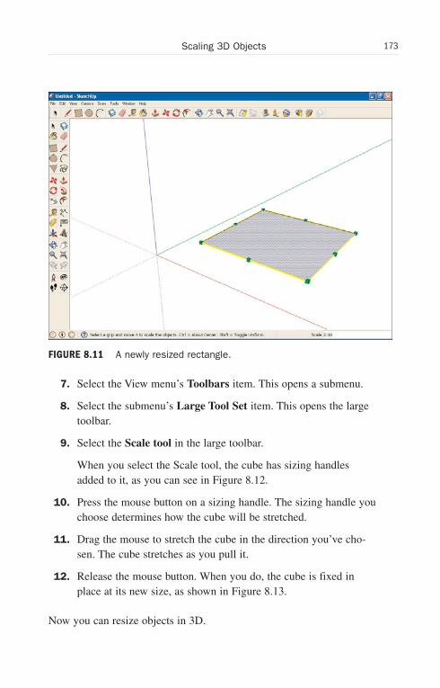
ptg6519239
173Scaling 3D Objects
FIGURE 8.11 A newly resized rectangle.
7. Select the View menu’s Toolbars item. This opens a submenu.
8. Select the submenu’s Large Tool Set item. This opens the largetoolbar.
9. Select the Scale tool in the large toolbar.
When you select the Scale tool, the cube has sizing handlesadded to it, as you can see in Figure 8.12.
10. Press the mouse button on a sizing handle. The sizing handle youchoose determines how the cube will be stretched.
11. Drag the mouse to stretch the cube in the direction you’ve cho-sen. The cube stretches as you pull it.
12. Release the mouse button. When you do, the cube is fixed inplace at its new size, as shown in Figure 8.13.
Now you can resize objects in 3D.
Wow! eBook <WoweBook.Com>
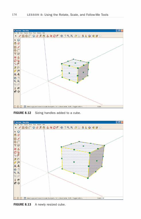
ptg6519239
174 LESSON 8: Using the Rotate, Scale, and Follow-Me Tools
FIGURE 8.12 Sizing handles added to a cube.
FIGURE 8.13 A newly resized cube.
Wow! eBook <WoweBook.Com>
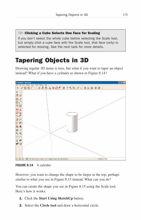
ptg6519239
175Tapering Objects in 3D
TIP: Clicking a Cube Selects One Face for Scaling
If you don’t select the whole cube before selecting the Scale tool,but simply click a cube face with the Scale tool, that face (only) isselected for resizing. See the next task for more details.
Tapering Objects in 3DDrawing regular 3D items is nice, but what if you want to taper an objectinstead? What if you have a cylinder as shown in Figure 8.14?
However, you want to change the shape to be larger at the top, perhapssimilar to what you see in Figure 8.15 instead. What can you do?
You can create the shape you see in Figure 8.15 using the Scale tool.Here’s how it works:
1. Click the Start Using SketchUp button.
2. Select the Circle tool and draw a horizontal circle.
FIGURE 8.14 A cylinder.
Wow! eBook <WoweBook.Com>
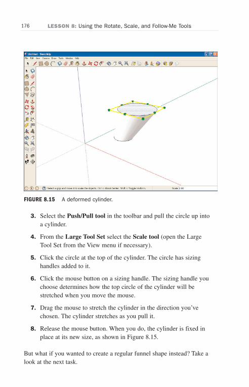
ptg6519239
176 LESSON 8: Using the Rotate, Scale, and Follow-Me Tools
FIGURE 8.15 A deformed cylinder.
3. Select the Push/Pull tool in the toolbar and pull the circle up intoa cylinder.
4. From the Large Tool Set select the Scale tool (open the LargeTool Set from the View menu if necessary).
5. Click the circle at the top of the cylinder. The circle has sizinghandles added to it.
6. Click the mouse button on a sizing handle. The sizing handle youchoose determines how the top circle of the cylinder will bestretched when you move the mouse.
7. Drag the mouse to stretch the cylinder in the direction you’vechosen. The cylinder stretches as you pull it.
8. Release the mouse button. When you do, the cylinder is fixed inplace at its new size, as shown in Figure 8.15.
But what if you wanted to create a regular funnel shape instead? Take alook at the next task.
Wow! eBook <WoweBook.Com>
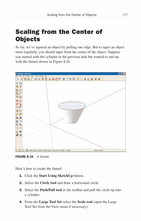
ptg6519239
177Scaling from the Center of Objects
Scaling from the Center ofObjectsSo far, we’ve tapered an object by pulling one edge. But to taper an objectmore regularly, you should taper from the center of the object. Supposeyou started with the cylinder in the previous task but wanted to end upwith the funnel shown in Figure 8.16.
Here’s how to create the funnel:
1. Click the Start Using SketchUp button.
2. Select the Circle tool and draw a horizontal circle.
3. Select the Push/Pull tool in the toolbar and pull the circle up intoa cylinder.
4. From the Large Tool Set select the Scale tool (open the LargeTool Set from the View menu if necessary).
FIGURE 8.16 A funnel.
Wow! eBook <WoweBook.Com>
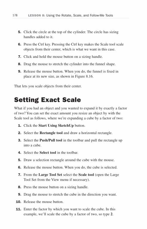
ptg6519239
178 LESSON 8: Using the Rotate, Scale, and Follow-Me Tools
5. Click the circle at the top of the cylinder. The circle has sizinghandles added to it.
6. Press the Ctrl key. Pressing the Ctrl key makes the Scale tool scaleobjects from their center, which is what we want in this case.
7. Click and hold the mouse button on a sizing handle.
8. Drag the mouse to stretch the cylinder into the funnel shape.
9. Release the mouse button. When you do, the funnel is fixed inplace at its new size, as shown in Figure 8.16.
That lets you scale objects from their center.
Setting Exact ScaleWhat if you had an object and you wanted to expand it by exactly a factorof two? You can set the exact amount you resize an object by with theScale tool as follows, where we’re expanding a cube by a factor of two:
1. Click the Start Using SketchUp button.
2. Select the Rectangle tool and draw a horizontal rectangle.
3. Select the Push/Pull tool in the toolbar and pull the rectangle upinto a cube.
4. Select the Select tool in the toolbar.
5. Draw a selection rectangle around the cube with the mouse.
6. Release the mouse button. When you do, the cube is selected.
7. From the Large Tool Set select the Scale tool (open the LargeTool Set from the View menu if necessary).
8. Press the mouse button on a sizing handle.
9. Drag the mouse to stretch the cube in the direction you want.
10. Release the mouse button.
11. Enter the factor by which you want to scale the cube. In thisexample, we’ll scale the cube by a factor of two, so type 2.
Wow! eBook <WoweBook.Com>
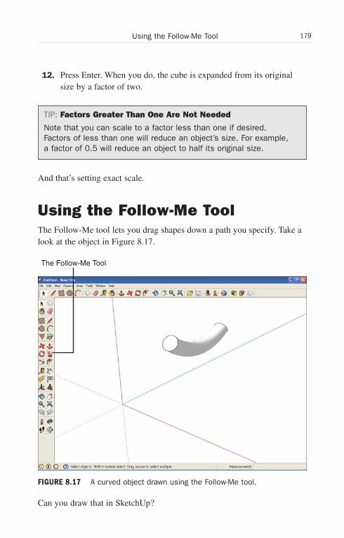
ptg6519239
179Using the Follow-Me Tool
12. Press Enter. When you do, the cube is expanded from its originalsize by a factor of two.
TIP: Factors Greater Than One Are Not Needed
Note that you can scale to a factor less than one if desired.Factors of less than one will reduce an object’s size. For example,a factor of 0.5 will reduce an object to half its original size.
And that’s setting exact scale.
Using the Follow-Me ToolThe Follow-Me tool lets you drag shapes down a path you specify. Take alook at the object in Figure 8.17.
Can you draw that in SketchUp?
The Follow-Me Tool
FIGURE 8.17 A curved object drawn using the Follow-Me tool.
Wow! eBook <WoweBook.Com>
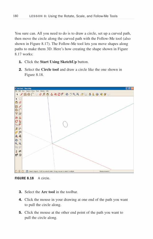
ptg6519239
180 LESSON 8: Using the Rotate, Scale, and Follow-Me Tools
You sure can. All you need to do is to draw a circle, set up a curved path,then move the circle along the curved path with the Follow-Me tool (alsoshown in Figure 8.17). The Follow-Me tool lets you move shapes alongpaths to make them 3D. Here’s how creating the shape shown in Figure8.17 works:
1. Click the Start Using SketchUp button.
2. Select the Circle tool and draw a circle like the one shown inFigure 8.18.
3. Select the Arc tool in the toolbar.
4. Click the mouse in your drawing at one end of the path you wantto pull the circle along.
5. Click the mouse at the other end point of the path you want topull the circle along.
FIGURE 8.18 A circle.
Wow! eBook <WoweBook.Com>
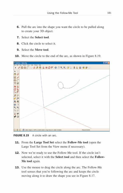
ptg6519239
181Using the Follow-Me Tool
6. Pull the arc into the shape you want the circle to be pulled alongto create your 3D object.
7. Select the Select tool.
8. Click the circle to select it.
9. Select the Move tool.
10. Move the circle to the end of the arc, as shown in Figure 8.19.
11. From the Large Tool Set select the Follow-Me tool (open theLarge Tool Set from the View menu if necessary).
12. Now we’re ready to use the Follow-Me tool. If the circle isn’tselected, select it with the Select tool and then select the Follow-Me tool again.
13. Use the mouse to drag the circle along the arc. The Follow-Metool senses that you’re following the arc and keeps the circlemoving along it to draw the shape you see in Figure 8.17.
FIGURE 8.19 A circle with an arc.
Wow! eBook <WoweBook.Com>

ptg6519239
182 LESSON 8: Using the Rotate, Scale, and Follow-Me Tools
TIP: You Don’t Have to Drag the Follow-Me Tool
You don’t have to drag the Follow-Me tool along a path if you don’twant to. Simply select the edges that form the path you want withthe Select tool so they appear as dotted lines (and form a connect-ed path). Then select the Follow-Me tool and click the shape youwant to have the Follow-Me tool drag around the path you selectedautomatically.
The Follow-Me tool is invaluable if you want to create a shape by movinganother shape along a certain path.
Wow! eBook <WoweBook.Com>
ptg6519239
LESSON 9
X-Raying Objects,Creating Guides andOffsets
In this lesson, we’re going to extend our SketchUp skill set by x-rayingobjects, creating construction guides, and offsetting edges to make copiesof them.
Getting StartedWhen you x-ray surfaces, you can see what’s behind them. That’s greatwhen your model gets more involved and objects start obstructing objectsand you don’t want to keep rotating around to see behind them.
You can create construction guides with the Tape Measure tool.Construction guides are dotted lines that you use for reference when mov-ing or aligning other objects, and they’re great when you’re laying out theparts of your model.
We’ll also see how to create offsets in this lesson. An offset is a copy of anedge that you can resize just by dragging the mouse, and offsets are veryuseful when you’re building items like doors and windows to build frames.
We’ll see all this in this lesson—let’s get started by giving some objectsthe X-ray treatment.
NOTE: Know Your Tools
It’s assumed in these tasks that you have been progressingthrough each lesson in order and learning about the individual toolsused here. In case you need to flip back for review, check out
Wow! eBook <WoweBook.Com>
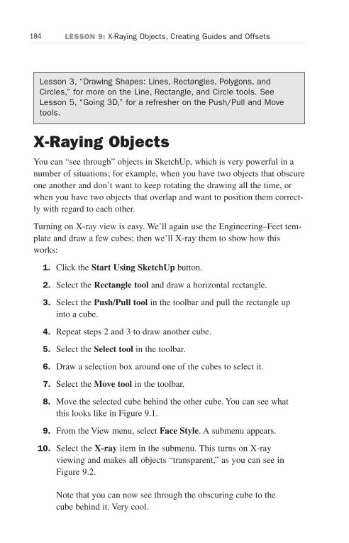
ptg6519239
184 LESSON 9: X-Raying Objects, Creating Guides and Offsets
Lesson 3, “Drawing Shapes: Lines, Rectangles, Polygons, andCircles,” for more on the Line, Rectangle, and Circle tools. SeeLesson 5, “Going 3D,” for a refresher on the Push/Pull and Movetools.
X-Raying ObjectsYou can “see through” objects in SketchUp, which is very powerful in anumber of situations; for example, when you have two objects that obscureone another and don’t want to keep rotating the drawing all the time, orwhen you have two objects that overlap and want to position them correct-ly with regard to each other.
Turning on X-ray view is easy. We’ll again use the Engineering–Feet tem-plate and draw a few cubes; then we’ll X-ray them to show how thisworks:
1. Click the Start Using SketchUp button.
2. Select the Rectangle tool and draw a horizontal rectangle.
3. Select the Push/Pull tool in the toolbar and pull the rectangle upinto a cube.
4. Repeat steps 2 and 3 to draw another cube.
5. Select the Select tool in the toolbar.
6. Draw a selection box around one of the cubes to select it.
7. Select the Move tool in the toolbar.
8. Move the selected cube behind the other cube. You can see whatthis looks like in Figure 9.1.
9. From the View menu, select Face Style. A submenu appears.
10. Select the X-ray item in the submenu. This turns on X-rayviewing and makes all objects “transparent,” as you can see inFigure 9.2.
Note that you can now see through the obscuring cube to thecube behind it. Very cool.
Wow! eBook <WoweBook.Com>
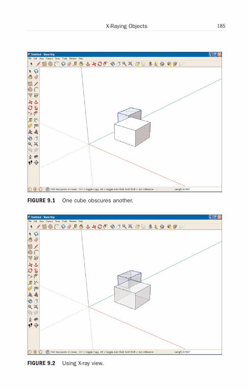
ptg6519239
185X-Raying Objects
FIGURE 9.2 Using X-ray view.
FIGURE 9.1 One cube obscures another.
Wow! eBook <WoweBook.Com>
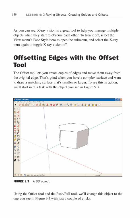
ptg6519239
186 LESSON 9: X-Raying Objects, Creating Guides and Offsets
As you can see, X-ray vision is a great tool to help you manage multipleobjects when they start to obscure each other. To turn it off, select theView menu’s Face Style item to open the submenu, and select the X-rayitem again to toggle X-ray vision off.
Offsetting Edges with the OffsetToolThe Offset tool lets you create copies of edges and move them away fromthe original edge. That’s good when you have a complex surface and wantto draw a matching surface that’s smaller or larger. To see this in action,we’ll start in this task with the object you see in Figure 9.3.
Using the Offset tool and the Push/Pull tool, we’ll change this object to theone you see in Figure 9.4 with just a couple of clicks.
FIGURE 9.3 A 3D object.
Wow! eBook <WoweBook.Com>

ptg6519239
187Offsetting Edges with the Offset Tool
Here’s how it works:
1. Click the Start Using SketchUp button.
2. Select Toolbars from the View menu. This opens a submenu.
3. Select the submenu’s Large Tool Set item. This opens the largetoolbar.
4. Select the Polygon tool in the Large Tool Set toolbar.
5. Draw a horizontal pentagon. Pentagons are the default polygondrawn by the Polygon tool.
6. Select the Push/Pull tool in the toolbar.
7. Pull the pentagon up into 3D.
Now we’ll use the Offset tool to draw the offsets we need.
The Offset Tool
FIGURE 9.4 Decorating an object using the Offset tool.
Wow! eBook <WoweBook.Com>
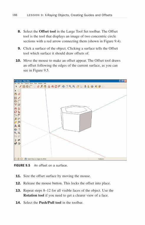
ptg6519239
188 LESSON 9: X-Raying Objects, Creating Guides and Offsets
8. Select the Offset tool in the Large Tool Set toolbar. The Offsettool is the tool that displays an image of two concentric circlesections with a red arrow connecting them (shown in Figure 9.4).
9. Click a surface of the object. Clicking a surface tells the Offsettool which surface it should draw offsets of.
10. Move the mouse to make an offset appear. The Offset tool drawsan offset following the edges of the current surface, as you cansee in Figure 9.5.
11. Size the offset surface by moving the mouse.
12. Release the mouse button. This locks the offset into place.
13. Repeat steps 8–12 for all visible faces of the object. Use theRotation tool if you need to get a clearer view of a face.
14. Select the Push/Pull tool in the toolbar.
FIGURE 9.5 An offset on a surface.
Wow! eBook <WoweBook.Com>
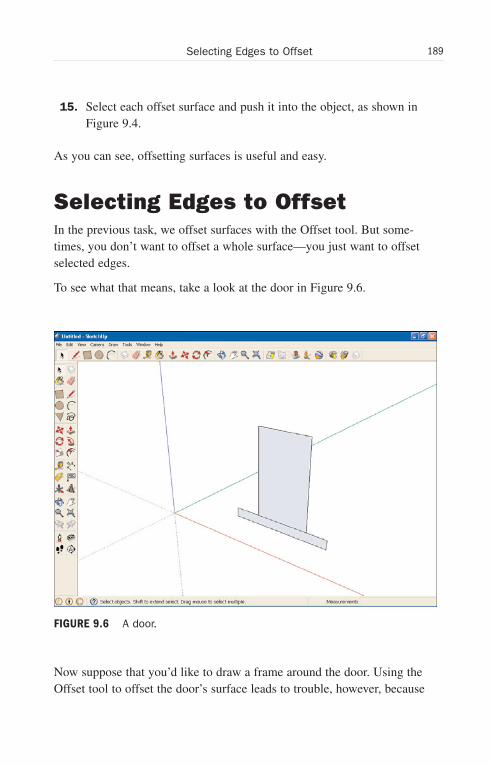
ptg6519239
189Selecting Edges to Offset
15. Select each offset surface and push it into the object, as shown inFigure 9.4.
As you can see, offsetting surfaces is useful and easy.
Selecting Edges to OffsetIn the previous task, we offset surfaces with the Offset tool. But some-times, you don’t want to offset a whole surface—you just want to offsetselected edges.
To see what that means, take a look at the door in Figure 9.6.
Now suppose that you’d like to draw a frame around the door. Using theOffset tool to offset the door’s surface leads to trouble, however, because
FIGURE 9.6 A door.
Wow! eBook <WoweBook.Com>

ptg6519239
190 LESSON 9: X-Raying Objects, Creating Guides and Offsets
the frame the Offset tool is drawing overlaps the lintel (the board at thebottom of a door), as you can see in Figure 9.7.
Wouldn’t it be nice if you could just offset the top three edges of the door,as shown in Figure 9.8?
That way, you could use the Offset tool to draw the door frame withouthaving the frame overlap the door’s lintel.
You can do this if you use the Offset tool with edges, not surfaces. Here’show it works:
1. Click the Start Using SketchUp button.
2. Select the Line tool in the Getting Started toolbar.
3. Draw the door and lintel as shown in Figure 9.6.
4. Select the Select tool in the toolbar.
FIGURE 9.7 An offset overlapping the lintel.
Wow! eBook <WoweBook.Com>
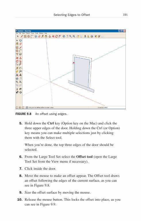
ptg6519239
191Selecting Edges to Offset
FIGURE 9.8 An offset using edges.
5. Hold down the Ctrl key (Option key on the Mac) and click thethree upper edges of the door. Holding down the Ctrl (or Option)key means you can make multiple selections just by clickingthem with the Select tool.
When you’re done, the top three edges of the door should beselected.
6. From the Large Tool Set select the Offset tool (open the LargeTool Set from the View menu if necessary).
7. Click inside the door.
8. Move the mouse to make an offset appear. The Offset tool drawsan offset following the edges of the current surface, as you cansee in Figure 9.8.
9. Size the offset surface by moving the mouse.
10. Release the mouse button. This locks the offset into place, as youcan see in Figure 9.9.
Wow! eBook <WoweBook.Com>
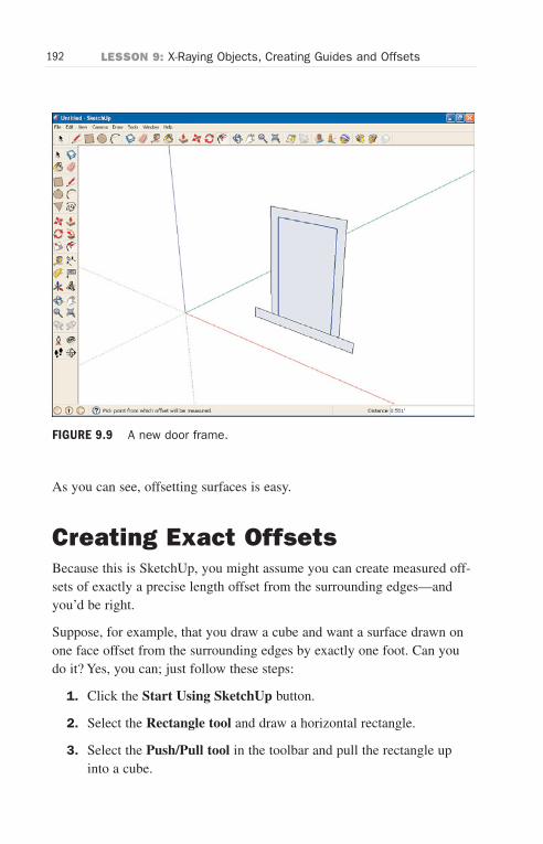
ptg6519239
192 LESSON 9: X-Raying Objects, Creating Guides and Offsets
As you can see, offsetting surfaces is easy.
Creating Exact OffsetsBecause this is SketchUp, you might assume you can create measured off-sets of exactly a precise length offset from the surrounding edges—andyou’d be right.
Suppose, for example, that you draw a cube and want a surface drawn onone face offset from the surrounding edges by exactly one foot. Can youdo it? Yes, you can; just follow these steps:
1. Click the Start Using SketchUp button.
2. Select the Rectangle tool and draw a horizontal rectangle.
3. Select the Push/Pull tool in the toolbar and pull the rectangle upinto a cube.
FIGURE 9.9 A new door frame.
Wow! eBook <WoweBook.Com>
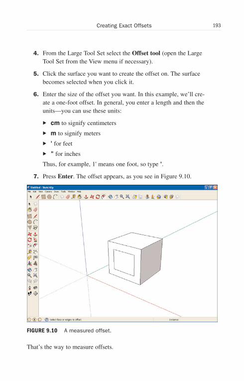
ptg6519239
193Creating Exact Offsets
4. From the Large Tool Set select the Offset tool (open the LargeTool Set from the View menu if necessary).
5. Click the surface you want to create the offset on. The surfacebecomes selected when you click it.
6. Enter the size of the offset you want. In this example, we’ll cre-ate a one-foot offset. In general, you enter a length and then theunits—you can use these units:
. cm to signify centimeters
. m to signify meters
. ' for feet
. " for inches
Thus, for example, 1' means one foot, so type '.
7. Press Enter. The offset appears, as you see in Figure 9.10.
That’s the way to measure offsets.
FIGURE 9.10 A measured offset.
Wow! eBook <WoweBook.Com>
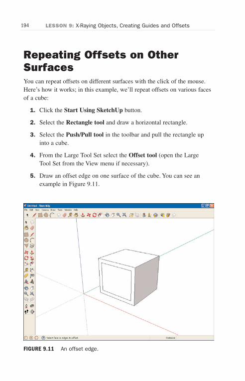
ptg6519239
194 LESSON 9: X-Raying Objects, Creating Guides and Offsets
Repeating Offsets on OtherSurfacesYou can repeat offsets on different surfaces with the click of the mouse.Here’s how it works; in this example, we’ll repeat offsets on various facesof a cube:
1. Click the Start Using SketchUp button.
2. Select the Rectangle tool and draw a horizontal rectangle.
3. Select the Push/Pull tool in the toolbar and pull the rectangle upinto a cube.
4. From the Large Tool Set select the Offset tool (open the LargeTool Set from the View menu if necessary).
5. Draw an offset edge on one surface of the cube. You can see anexample in Figure 9.11.
FIGURE 9.11 An offset edge.
Wow! eBook <WoweBook.Com>
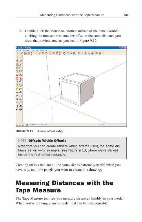
ptg6519239
195Measuring Distances with the Tape Measure
6. Double-click the mouse on another surface of the cube. Double-clicking the mouse draws another offset at the same distance youdrew the previous one, as you see in Figure 9.12.
NOTE: Offsets Within Offsets
Note that you can create offsets within offsets using the same dis-tance as well—for example, see Figure 9.13, where we’ve clickedinside the first offset rectangle.
Creating offsets that are all the same size is extremely useful when youhave, say, multiple panels you want to create in a drawing.
Measuring Distances with theTape MeasureThe Tape Measure tool lets you measure distances handily in your model.When you’re drawing plans to scale, that can be indispensable.
FIGURE 9.12 A new offset edge.
Wow! eBook <WoweBook.Com>
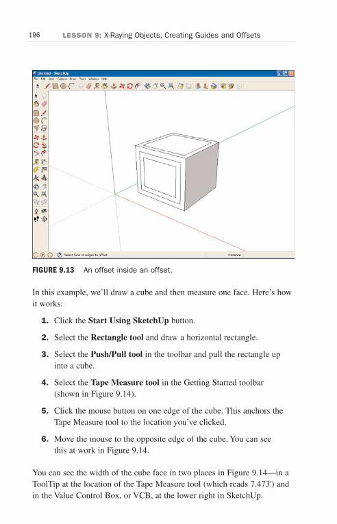
ptg6519239
196 LESSON 9: X-Raying Objects, Creating Guides and Offsets
FIGURE 9.13 An offset inside an offset.
In this example, we’ll draw a cube and then measure one face. Here’s howit works:
1. Click the Start Using SketchUp button.
2. Select the Rectangle tool and draw a horizontal rectangle.
3. Select the Push/Pull tool in the toolbar and pull the rectangle upinto a cube.
4. Select the Tape Measure tool in the Getting Started toolbar(shown in Figure 9.14).
5. Click the mouse button on one edge of the cube. This anchors theTape Measure tool to the location you’ve clicked.
6. Move the mouse to the opposite edge of the cube. You can seethis at work in Figure 9.14.
You can see the width of the cube face in two places in Figure 9.14—in aToolTip at the location of the Tape Measure tool (which reads 7.473') andin the Value Control Box, or VCB, at the lower right in SketchUp.
Wow! eBook <WoweBook.Com>
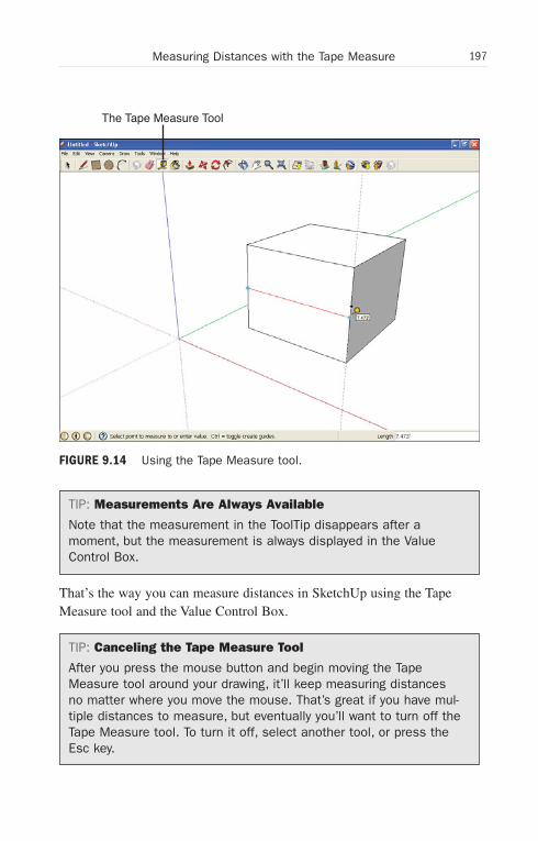
ptg6519239
197Measuring Distances with the Tape Measure
The Tape Measure Tool
FIGURE 9.14 Using the Tape Measure tool.
TIP: Measurements Are Always Available
Note that the measurement in the ToolTip disappears after amoment, but the measurement is always displayed in the ValueControl Box.
That’s the way you can measure distances in SketchUp using the TapeMeasure tool and the Value Control Box.
TIP: Canceling the Tape Measure Tool
After you press the mouse button and begin moving the TapeMeasure tool around your drawing, it’ll keep measuring distancesno matter where you move the mouse. That’s great if you have mul-tiple distances to measure, but eventually you’ll want to turn off theTape Measure tool. To turn it off, select another tool, or press theEsc key.
Wow! eBook <WoweBook.Com>
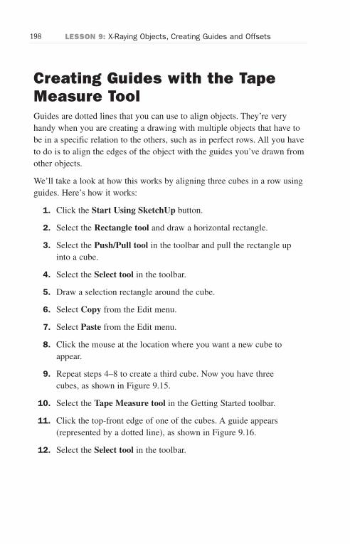
ptg6519239
198 LESSON 9: X-Raying Objects, Creating Guides and Offsets
Creating Guides with the TapeMeasure ToolGuides are dotted lines that you can use to align objects. They’re veryhandy when you are creating a drawing with multiple objects that have tobe in a specific relation to the others, such as in perfect rows. All you haveto do is to align the edges of the object with the guides you’ve drawn fromother objects.
We’ll take a look at how this works by aligning three cubes in a row usingguides. Here’s how it works:
1. Click the Start Using SketchUp button.
2. Select the Rectangle tool and draw a horizontal rectangle.
3. Select the Push/Pull tool in the toolbar and pull the rectangle upinto a cube.
4. Select the Select tool in the toolbar.
5. Draw a selection rectangle around the cube.
6. Select Copy from the Edit menu.
7. Select Paste from the Edit menu.
8. Click the mouse at the location where you want a new cube toappear.
9. Repeat steps 4–8 to create a third cube. Now you have threecubes, as shown in Figure 9.15.
10. Select the Tape Measure tool in the Getting Started toolbar.
11. Click the top-front edge of one of the cubes. A guide appears(represented by a dotted line), as shown in Figure 9.16.
12. Select the Select tool in the toolbar.
Wow! eBook <WoweBook.Com>
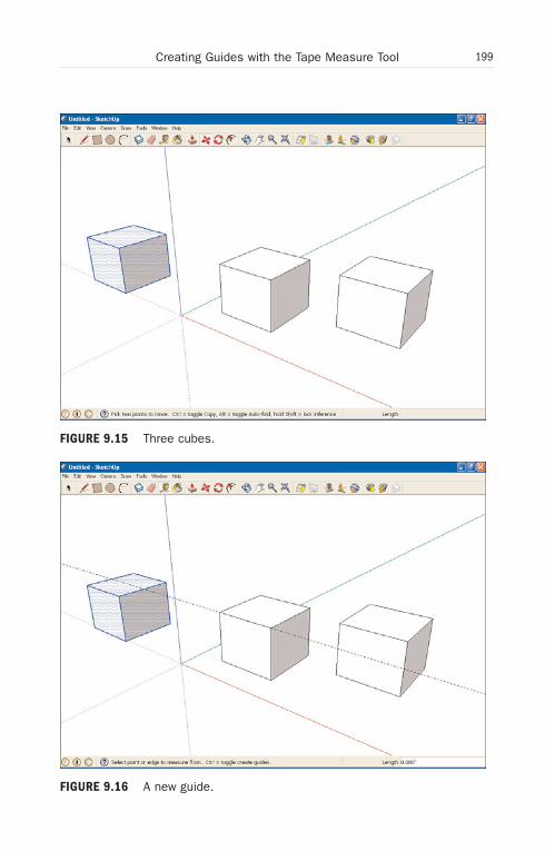
ptg6519239
199Creating Guides with the Tape Measure Tool
FIGURE 9.15 Three cubes.
FIGURE 9.16 A new guide.
Wow! eBook <WoweBook.Com>
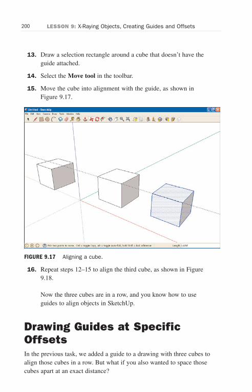
ptg6519239
200 LESSON 9: X-Raying Objects, Creating Guides and Offsets
13. Draw a selection rectangle around a cube that doesn’t have theguide attached.
14. Select the Move tool in the toolbar.
15. Move the cube into alignment with the guide, as shown inFigure 9.17.
16. Repeat steps 12–15 to align the third cube, as shown in Figure9.18.
Now the three cubes are in a row, and you know how to useguides to align objects in SketchUp.
Drawing Guides at SpecificOffsetsIn the previous task, we added a guide to a drawing with three cubes toalign those cubes in a row. But what if you also wanted to space thosecubes apart at an exact distance?
FIGURE 9.17 Aligning a cube.
Wow! eBook <WoweBook.Com>
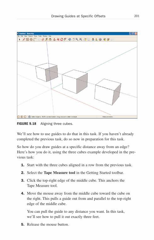
ptg6519239
201Drawing Guides at Specific Offsets
FIGURE 9.18 Aligning three cubes.
We’ll see how to use guides to do that in this task. If you haven’t alreadycompleted the previous task, do so now in preparation for this task.
So how do you draw guides at a specific distance away from an edge?Here’s how you do it, using the three cubes example developed in the pre-vious task:
1. Start with the three cubes aligned in a row from the previous task.
2. Select the Tape Measure tool in the Getting Started toolbar.
3. Click the top-right edge of the middle cube. This anchors theTape Measure tool.
4. Move the mouse away from the middle cube toward the cube onthe right. This pulls a guide out from and parallel to the top-rightedge of the middle cube.
You can pull the guide to any distance you want. In this task,we’ll see how to pull it out exactly three feet.
5. Release the mouse button.
Wow! eBook <WoweBook.Com>
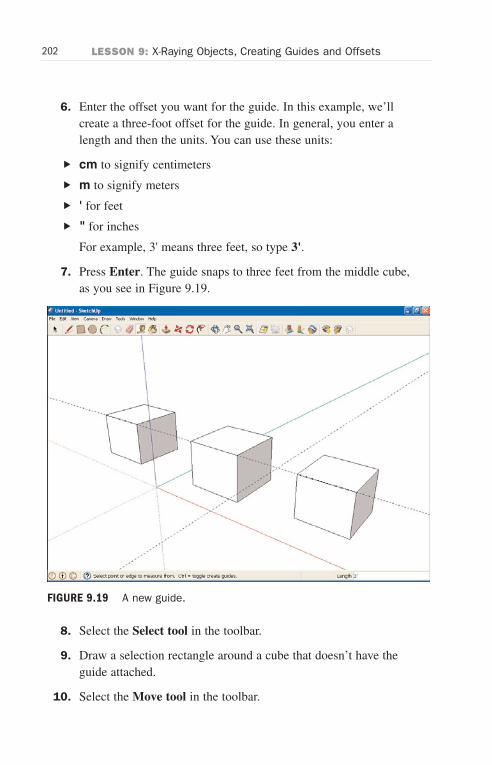
ptg6519239
202 LESSON 9: X-Raying Objects, Creating Guides and Offsets
6. Enter the offset you want for the guide. In this example, we’llcreate a three-foot offset for the guide. In general, you enter alength and then the units. You can use these units:
. cm to signify centimeters
. m to signify meters
. ' for feet
. " for inches
For example, 3' means three feet, so type 3'.
7. Press Enter. The guide snaps to three feet from the middle cube,as you see in Figure 9.19.
8. Select the Select tool in the toolbar.
9. Draw a selection rectangle around a cube that doesn’t have theguide attached.
10. Select the Move tool in the toolbar.
FIGURE 9.19 A new guide.
Wow! eBook <WoweBook.Com>

ptg6519239
203Drawing Guides at Specific Offsets
11. Move the cube into alignment with the new guide, spacing it atthree feet from the middle cube.
12. Select the Tape Measure tool in the Getting Started toolbar.
13. Click the top-left edge of the middle cube. This anchors the TapeMeasure tool.
14. Move the mouse away from the middle cube toward the cube onthe left.
15. Enter the offset you want for the guide. In this example, we’llcreate a three-foot offset for the guide, so type 3'.
16. Press Enter.
17. Repeat steps 8–11 to move the left cube into alignment.
Now your cubes are in a row, and evenly spaced, as you see inFigure 9.20.
FIGURE 9.20 Three cubes in a row, evenly spaced.
Wow! eBook <WoweBook.Com>
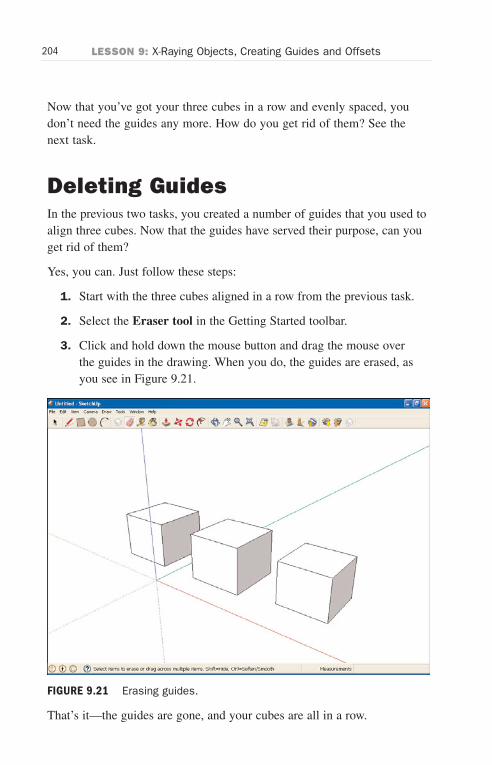
ptg6519239
204 LESSON 9: X-Raying Objects, Creating Guides and Offsets
Now that you’ve got your three cubes in a row and evenly spaced, youdon’t need the guides any more. How do you get rid of them? See thenext task.
Deleting GuidesIn the previous two tasks, you created a number of guides that you used toalign three cubes. Now that the guides have served their purpose, can youget rid of them?
Yes, you can. Just follow these steps:
1. Start with the three cubes aligned in a row from the previous task.
2. Select the Eraser tool in the Getting Started toolbar.
3. Click and hold down the mouse button and drag the mouse overthe guides in the drawing. When you do, the guides are erased, asyou see in Figure 9.21.
That’s it—the guides are gone, and your cubes are all in a row.
FIGURE 9.21 Erasing guides.
Wow! eBook <WoweBook.Com>
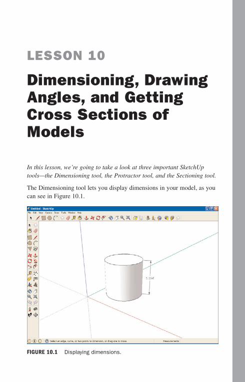
ptg6519239
LESSON 10
Dimensioning, DrawingAngles, and GettingCross Sections ofModels
In this lesson, we’re going to take a look at three important SketchUptools—the Dimensioning tool, the Protractor tool, and the Sectioning tool.
The Dimensioning tool lets you display dimensions in your model, as youcan see in Figure 10.1.
FIGURE 10.1 Displaying dimensions.
Wow! eBook <WoweBook.Com>
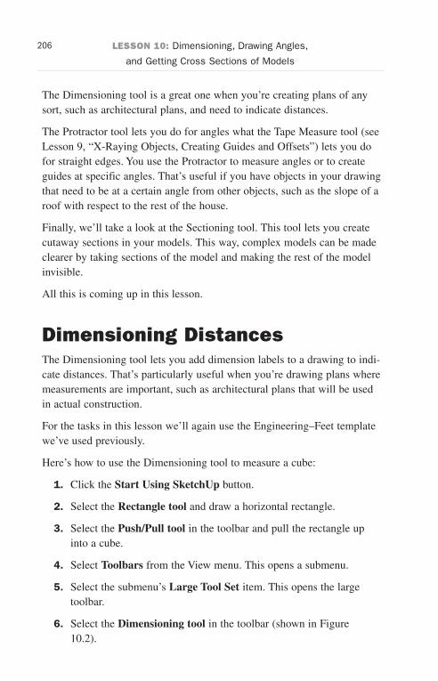
ptg6519239
206 LESSON 10: Dimensioning, Drawing Angles,
and Getting Cross Sections of Models
The Dimensioning tool is a great one when you’re creating plans of anysort, such as architectural plans, and need to indicate distances.
The Protractor tool lets you do for angles what the Tape Measure tool (seeLesson 9, “X-Raying Objects, Creating Guides and Offsets”) lets you dofor straight edges. You use the Protractor to measure angles or to createguides at specific angles. That’s useful if you have objects in your drawingthat need to be at a certain angle from other objects, such as the slope of aroof with respect to the rest of the house.
Finally, we’ll take a look at the Sectioning tool. This tool lets you createcutaway sections in your models. This way, complex models can be madeclearer by taking sections of the model and making the rest of the modelinvisible.
All this is coming up in this lesson.
Dimensioning DistancesThe Dimensioning tool lets you add dimension labels to a drawing to indi-cate distances. That’s particularly useful when you’re drawing plans wheremeasurements are important, such as architectural plans that will be usedin actual construction.
For the tasks in this lesson we’ll again use the Engineering–Feet templatewe’ve used previously.
Here’s how to use the Dimensioning tool to measure a cube:
1. Click the Start Using SketchUp button.
2. Select the Rectangle tool and draw a horizontal rectangle.
3. Select the Push/Pull tool in the toolbar and pull the rectangle upinto a cube.
4. Select Toolbars from the View menu. This opens a submenu.
5. Select the submenu’s Large Tool Set item. This opens the largetoolbar.
6. Select the Dimensioning tool in the toolbar (shown in Figure10.2).
Wow! eBook <WoweBook.Com>
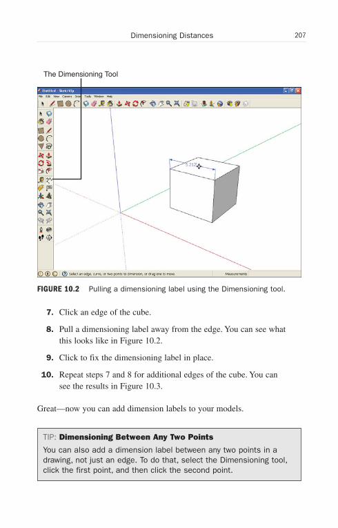
ptg6519239
207Dimensioning Distances
The Dimensioning Tool
FIGURE 10.2 Pulling a dimensioning label using the Dimensioning tool.
7. Click an edge of the cube.
8. Pull a dimensioning label away from the edge. You can see whatthis looks like in Figure 10.2.
9. Click to fix the dimensioning label in place.
10. Repeat steps 7 and 8 for additional edges of the cube. You cansee the results in Figure 10.3.
Great—now you can add dimension labels to your models.
TIP: Dimensioning Between Any Two Points
You can also add a dimension label between any two points in adrawing, not just an edge. To do that, select the Dimensioning tool,click the first point, and then click the second point.
Wow! eBook <WoweBook.Com>
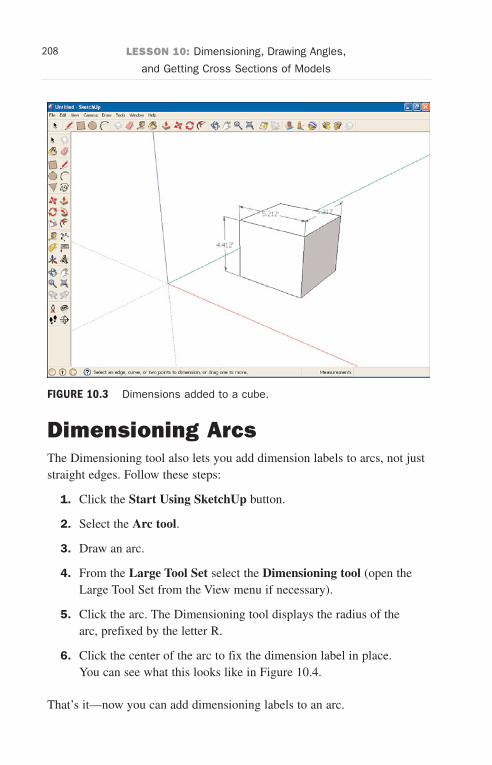
ptg6519239
208 LESSON 10: Dimensioning, Drawing Angles,
and Getting Cross Sections of Models
FIGURE 10.3 Dimensions added to a cube.
Dimensioning ArcsThe Dimensioning tool also lets you add dimension labels to arcs, not juststraight edges. Follow these steps:
1. Click the Start Using SketchUp button.
2. Select the Arc tool.
3. Draw an arc.
4. From the Large Tool Set select the Dimensioning tool (open theLarge Tool Set from the View menu if necessary).
5. Click the arc. The Dimensioning tool displays the radius of thearc, prefixed by the letter R.
6. Click the center of the arc to fix the dimension label in place.You can see what this looks like in Figure 10.4.
That’s it—now you can add dimensioning labels to an arc.
Wow! eBook <WoweBook.Com>

ptg6519239
209Freezing Dimensions
FIGURE 10.4 Dimensioning an arc.
Freezing DimensionsWhen you resize an object that has a dimensioning label attached to it, thelabel is updated with the new length by default. However, you can lock thedimension label’s displayed length so that it won’t change no matter howmuch you resize the object. Here’s how:
1. Click the Start Using SketchUp button.
2. Select the Rectangle tool and draw a horizontal rectangle.
3. Select the Push/Pull tool in the toolbar and pull the rectangle upinto a cube.
4. From the Large Tool Set select the Dimensioning tool (open theLarge Tool Set from the View menu if necessary).
5. Click an edge of the cube.
6. Pull a dimensioning guide away from the edge to create a dimen-sioning label.
Wow! eBook <WoweBook.Com>
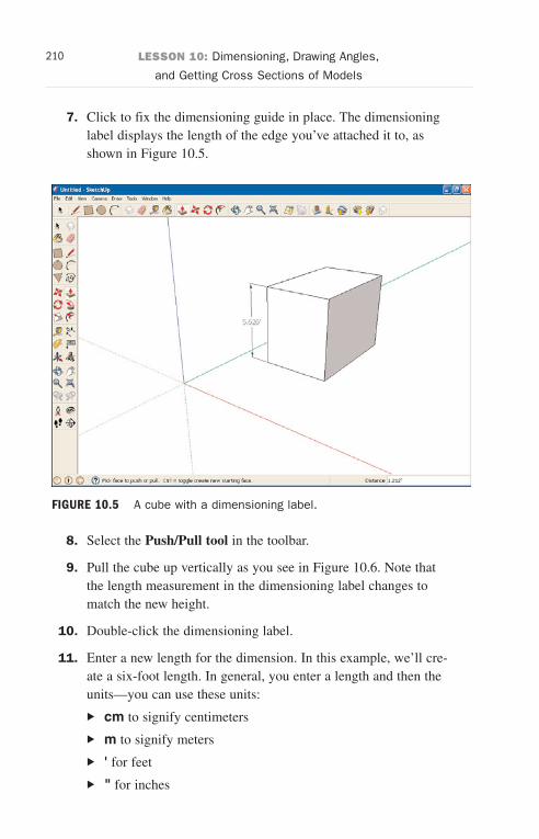
ptg6519239
210 LESSON 10: Dimensioning, Drawing Angles,
and Getting Cross Sections of Models
7. Click to fix the dimensioning guide in place. The dimensioninglabel displays the length of the edge you’ve attached it to, asshown in Figure 10.5.
8. Select the Push/Pull tool in the toolbar.
9. Pull the cube up vertically as you see in Figure 10.6. Note thatthe length measurement in the dimensioning label changes tomatch the new height.
10. Double-click the dimensioning label.
11. Enter a new length for the dimension. In this example, we’ll cre-ate a six-foot length. In general, you enter a length and then theunits—you can use these units:
. cm to signify centimeters
. m to signify meters
. ' for feet
. " for inches
FIGURE 10.5 A cube with a dimensioning label.
Wow! eBook <WoweBook.Com>
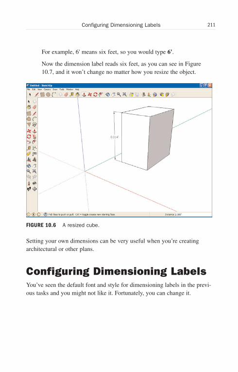
ptg6519239
211Configuring Dimensioning Labels
FIGURE 10.6 A resized cube.
Setting your own dimensions can be very useful when you’re creatingarchitectural or other plans.
Configuring Dimensioning LabelsYou’ve seen the default font and style for dimensioning labels in the previ-ous tasks and you might not like it. Fortunately, you can change it.
For example, 6' means six feet, so you would type 6'.
Now the dimension label reads six feet, as you can see in Figure10.7, and it won’t change no matter how you resize the object.
Wow! eBook <WoweBook.Com>
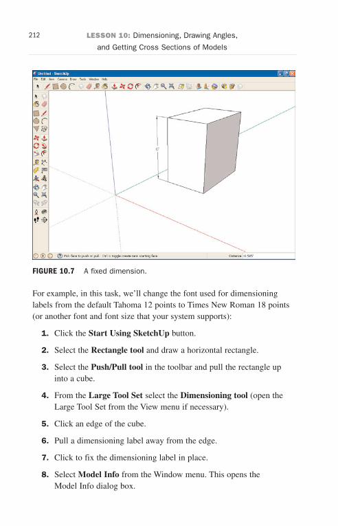
ptg6519239
212 LESSON 10: Dimensioning, Drawing Angles,
and Getting Cross Sections of Models
FIGURE 10.7 A fixed dimension.
For example, in this task, we’ll change the font used for dimensioninglabels from the default Tahoma 12 points to Times New Roman 18 points(or another font and font size that your system supports):
1. Click the Start Using SketchUp button.
2. Select the Rectangle tool and draw a horizontal rectangle.
3. Select the Push/Pull tool in the toolbar and pull the rectangle upinto a cube.
4. From the Large Tool Set select the Dimensioning tool (open theLarge Tool Set from the View menu if necessary).
5. Click an edge of the cube.
6. Pull a dimensioning label away from the edge.
7. Click to fix the dimensioning label in place.
8. Select Model Info from the Window menu. This opens theModel Info dialog box.
Wow! eBook <WoweBook.Com>
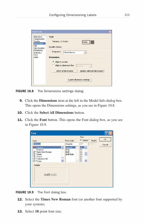
ptg6519239
213Configuring Dimensioning Labels
FIGURE 10.8 The Dimensions settings dialog.
9. Click the Dimensions item at the left in the Model Info dialog box.This opens the Dimensions settings, as you see in Figure 10.8.
10. Click the Select All Dimensions button.
11. Click the Font button. This opens the Font dialog box, as you seein Figure 10.9.
12. Select the Times New Roman font (or another font supported byyour system).
13. Select 18 point font size.
FIGURE 10.9 The Font dialog box.
Wow! eBook <WoweBook.Com>
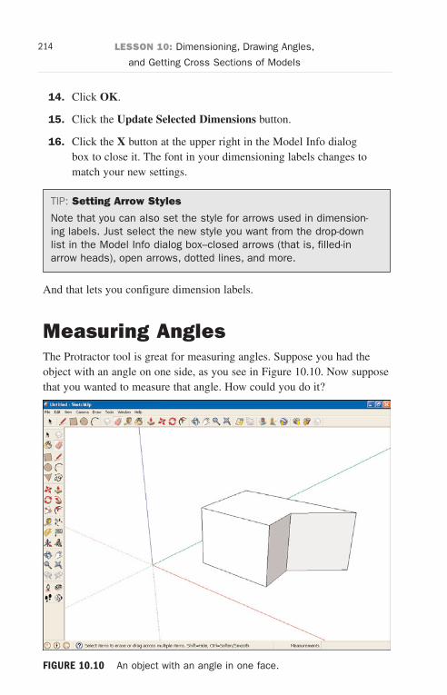
ptg6519239
214 LESSON 10: Dimensioning, Drawing Angles,
and Getting Cross Sections of Models
14. Click OK.
15. Click the Update Selected Dimensions button.
16. Click the X button at the upper right in the Model Info dialogbox to close it. The font in your dimensioning labels changes tomatch your new settings.
TIP: Setting Arrow Styles
Note that you can also set the style for arrows used in dimension-ing labels. Just select the new style you want from the drop-downlist in the Model Info dialog box–closed arrows (that is, filled-inarrow heads), open arrows, dotted lines, and more.
And that lets you configure dimension labels.
Measuring AnglesThe Protractor tool is great for measuring angles. Suppose you had theobject with an angle on one side, as you see in Figure 10.10. Now supposethat you wanted to measure that angle. How could you do it?
FIGURE 10.10 An object with an angle in one face.
Wow! eBook <WoweBook.Com>
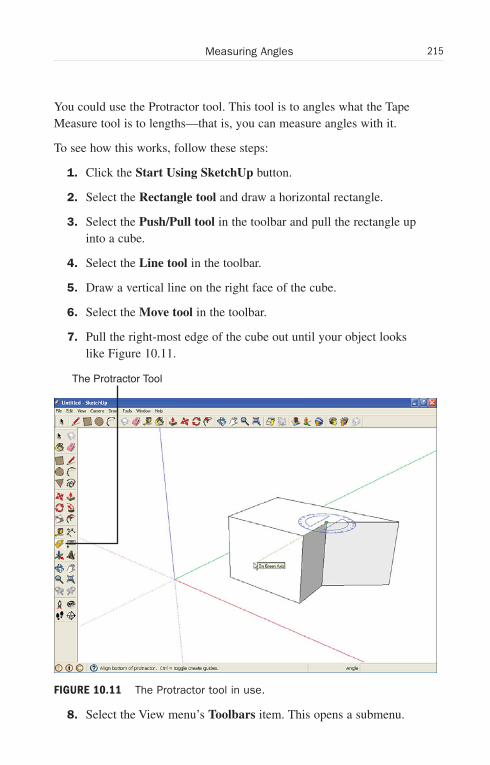
ptg6519239
215Measuring Angles
You could use the Protractor tool. This tool is to angles what the TapeMeasure tool is to lengths—that is, you can measure angles with it.
To see how this works, follow these steps:
1. Click the Start Using SketchUp button.
2. Select the Rectangle tool and draw a horizontal rectangle.
3. Select the Push/Pull tool in the toolbar and pull the rectangle upinto a cube.
4. Select the Line tool in the toolbar.
5. Draw a vertical line on the right face of the cube.
6. Select the Move tool in the toolbar.
7. Pull the right-most edge of the cube out until your object lookslike Figure 10.11.
8. Select the View menu’s Toolbars item. This opens a submenu.
The Protractor Tool
FIGURE 10.11 The Protractor tool in use.
Wow! eBook <WoweBook.Com>
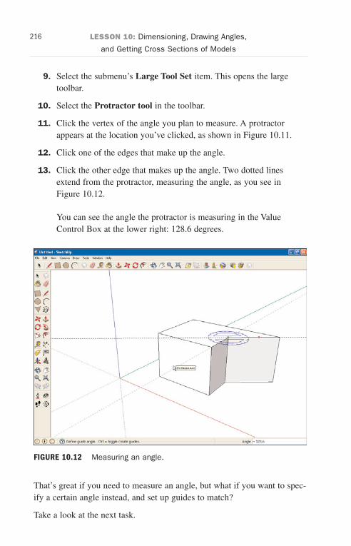
ptg6519239
216 LESSON 10: Dimensioning, Drawing Angles,
and Getting Cross Sections of Models
9. Select the submenu’s Large Tool Set item. This opens the largetoolbar.
10. Select the Protractor tool in the toolbar.
11. Click the vertex of the angle you plan to measure. A protractorappears at the location you’ve clicked, as shown in Figure 10.11.
12. Click one of the edges that make up the angle.
13. Click the other edge that makes up the angle. Two dotted linesextend from the protractor, measuring the angle, as you see inFigure 10.12.
You can see the angle the protractor is measuring in the ValueControl Box at the lower right: 128.6 degrees.
That’s great if you need to measure an angle, but what if you want to spec-ify a certain angle instead, and set up guides to match?
Take a look at the next task.
FIGURE 10.12 Measuring an angle.
Wow! eBook <WoweBook.Com>
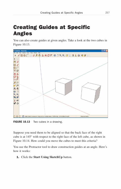
ptg6519239
217Creating Guides at Specific Angles
Creating Guides at SpecificAnglesYou can also create guides at given angles. Take a look at the two cubes inFigure 10.13.
Suppose you need them to be aligned so that the back face of the rightcube is at 145° with respect to the right face of the left cube, as shown inFigure 10.14. How could you move the cubes to meet this criteria?
You use the Protractor tool to draw construction guides at an angle. Here’show it works:
1. Click the Start Using SketchUp button.
FIGURE 10.13 Two cubes in a drawing.
Wow! eBook <WoweBook.Com>
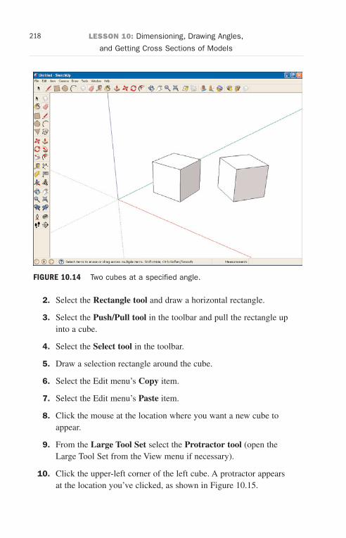
ptg6519239
218 LESSON 10: Dimensioning, Drawing Angles,
and Getting Cross Sections of Models
FIGURE 10.14 Two cubes at a specified angle.
2. Select the Rectangle tool and draw a horizontal rectangle.
3. Select the Push/Pull tool in the toolbar and pull the rectangle upinto a cube.
4. Select the Select tool in the toolbar.
5. Draw a selection rectangle around the cube.
6. Select the Edit menu’s Copy item.
7. Select the Edit menu’s Paste item.
8. Click the mouse at the location where you want a new cube toappear.
9. From the Large Tool Set select the Protractor tool (open theLarge Tool Set from the View menu if necessary).
10. Click the upper-left corner of the left cube. A protractor appearsat the location you’ve clicked, as shown in Figure 10.15.
Wow! eBook <WoweBook.Com>
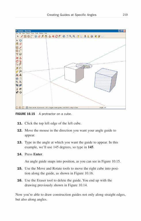
ptg6519239
219Creating Guides at Specific Angles
11. Click the top left edge of the left cube.
12. Move the mouse in the direction you want your angle guide toappear.
13. Type in the angle at which you want the guide to appear. In thisexample, we’ll use 145 degrees, so type in 145.
14. Press Enter.
An angle guide snaps into position, as you can see in Figure 10.15.
15. Use the Move and Rotate tools to move the right cube into posi-tion along the guide, as shown in Figure 10.16.
16. Use the Eraser tool to delete the guide. You end up with thedrawing previously shown in Figure 10.14.
Now you’re able to draw construction guides not only along straight edges,but also along angles.
FIGURE 10.15 A protractor on a cube.
Wow! eBook <WoweBook.Com>
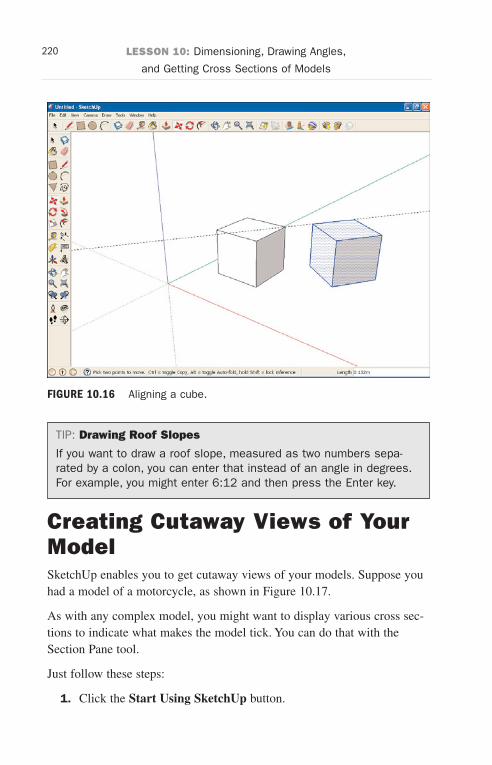
ptg6519239
220 LESSON 10: Dimensioning, Drawing Angles,
and Getting Cross Sections of Models
FIGURE 10.16 Aligning a cube.
TIP: Drawing Roof Slopes
If you want to draw a roof slope, measured as two numbers sepa-rated by a colon, you can enter that instead of an angle in degrees.For example, you might enter 6:12 and then press the Enter key.
Creating Cutaway Views of YourModelSketchUp enables you to get cutaway views of your models. Suppose youhad a model of a motorcycle, as shown in Figure 10.17.
As with any complex model, you might want to display various cross sec-tions to indicate what makes the model tick. You can do that with theSection Pane tool.
Just follow these steps:
1. Click the Start Using SketchUp button.
Wow! eBook <WoweBook.Com>
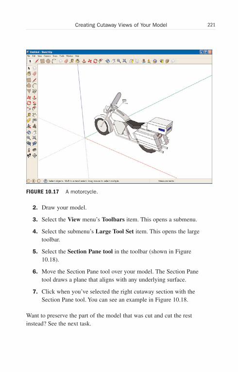
ptg6519239
221Creating Cutaway Views of Your Model
FIGURE 10.17 A motorcycle.
2. Draw your model.
3. Select the View menu’s Toolbars item. This opens a submenu.
4. Select the submenu’s Large Tool Set item. This opens the largetoolbar.
5. Select the Section Pane tool in the toolbar (shown in Figure10.18).
6. Move the Section Pane tool over your model. The Section Panetool draws a plane that aligns with any underlying surface.
7. Click when you’ve selected the right cutaway section with theSection Pane tool. You can see an example in Figure 10.18.
Want to preserve the part of the model that was cut and cut the restinstead? See the next task.
Wow! eBook <WoweBook.Com>
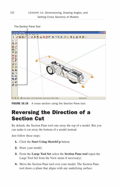
ptg6519239
222 LESSON 10: Dimensioning, Drawing Angles, and
Getting Cross Sections of Models
The Section Pane Tool
FIGURE 10.18 A cross section using the Section Pane tool.
Reversing the Direction of aSection CutBy default, the Section Pane tool cuts away the top of a model. But youcan make it cut away the bottom of a model instead.
Just follow these steps:
1. Click the Start Using SketchUp button.
2. Draw your model.
3. From the Large Tool Set select the Section Pane tool (open theLarge Tool Set from the View menu if necessary).
4. Move the Section Pane tool over your model. The Section Panetool draws a plane that aligns with any underlying surface.
Wow! eBook <WoweBook.Com>
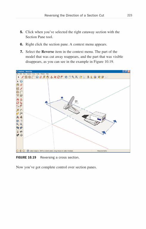
ptg6519239
223Reversing the Direction of a Section Cut
5. Click when you’ve selected the right cutaway section with theSection Pane tool.
6. Right click the section pane. A context menu appears.
7. Select the Reverse item in the context menu. The part of themodel that was cut away reappears, and the part that was visibledisappears, as you can see in the example in Figure 10.19.
Now you’ve got complete control over section panes.
FIGURE 10.19 Reversing a cross section.
Wow! eBook <WoweBook.Com>

ptg6519239
This page intentionally left blank
Wow! eBook <WoweBook.Com>

ptg6519239
2D objects3D objects
drawing, subtracting elementsmethod, 115-117
scaling, 172-175tapering, 175-176text, drawing, 91-93
3D Text tool, 91-933D Warehouse, 136-138
Aacute angles, rounding, 76-79aligning objects with guides,
198-201angles
construction guides, creating,217-220
of guides, setting, 217-220measuring, 214-216
annotating objects with text, 86-88Arc tool, 75arcs
dimensioning, 208drawing, 73-75
multiple tangent arcs, drawing,79-80
number of segments, setting,80-81
tangent to corners, drawing,76-79
automatic shading, eliminating,146-147
axes, 44-45
Ccanceling operations, 160Circle tool, 62-64circles
drawing, 62-64number of sides, setting, 67-69
collections, 18-19texture collections, 145-146
component libraries, 18-19Component Sampler, 135-136components, 129-130
3D Warehouse, 136-138comparing to groups, 129-130creating, 125-127
Index
Wow! eBook <WoweBook.Com>
ptg6519239
editing, 127-128exploding, 132-133managing, 133-134
Components dialog box, 135configuring dimensioning labels,
211-214construction guides, 22-23
creating, 217-220converting 2D objects to 3D, 9-12copying
objects, 110-112creating
components, 125-127construction guides, 217-220cutaway model views, 220-221exact offsets, 192-193funnels, 177-178groups, 121-125guides, 198-201materials, 152-154
crossing edges, 55cutaway model views, creating,
220-221cutting openings with Push/Pull tool,
103-106
Ddialog boxes
Components dialog box, 135Font, 89Instructor, 36
dimensioningarcs, 208distances, 206-207
dimensioning indicators, 22-23
dimensioning labels, configuring,211-214
Dimensioning tool, 206-208dimensions, freezing, 209-212distances
dimensioning, 206-207measuring, 195-197
draggingcircles, 64shapes, 179-182
drawing3D objects, subtracting
elements method, 115-1173D text, 91-93arcs, 73-75
multiple tangent arcs,79-80
circles, 62-64edges, 48-50freehand, 82guides at specific offsets,
200-204lines, 7, 56-57measured arcs, 75-76measured circles, 64measured lines, 59-60measured polygons, 66-67multiline shapes, 57-59polygons, 65-67rectangles, 60-62simple figures, 7-9surfaces freehand, 83text, 84-86textures, 145-146
226 components
Wow! eBook <WoweBook.Com>
ptg6519239
Eedges, 45-48
crossing, 55drawing, 48-50, 56-57erasing, 106-107inferring, 50-53moving, 112-114offsetting, 186-192selecting, 109-110
editingcomponents, 127-128materials, 154-155
eliminating automatic shading,146-147
Eraser tool, 106-107erasing edges, 106-107exact offsets, creating, 192-193exact scale of objects, setting,
178-179examining textures in your model,
151-152exploding components, 132-133
FFollow-Me tool, 25, 179-182Font dialog box, 89freehand, drawing, 82Freehand tool, 82freezing dimensions, 209-212funnels, creating, 177-178
Ggeometry, sticky geometry, 120-121groups
comparing to components,129-130
creating, 121-125guides
creating, 198-201deleting, 204drawing at specific offsets,
200-204specific angles, setting, 217-220
Hhealing a surface, 45
Iinferring
edges, 50-53push/pull, 101-103
installing SketchUp, 30-33Instructor dialog box, 36
LLicense Agreement page, 30-33Line tool
edges, drawing, 48-50measured lines, drawing, 59-60multiline shapes, drawing,
57-59
How can we make this index more useful? Email us at [email protected]
227Line tool
Wow! eBook <WoweBook.Com>
ptg6519239
lines, drawing, 7, 56-57locking Rotate tool orientation,
168-171
Mmanaging components, 133-134materials
creating, 152-154editing, 154-155replacing, 156-157sampling, 157-159
materials browser, 143materials, selecting, 145-146
measured arcs, drawing, 75-76measured circles, drawing, 64measured lines, drawing, 59-60measured offsets, 192-193measured polygons, drawing, 66-67measured push/pull, 100-101measured rectangles, drawing, 60-62measuring distances, 195-197menu bar, 37models, creating cutaway views,
220-221Move tool, 15, 112-114moving
edges, 112-114surfaces, 112-114
multiline shapes, drawing, 57-59multiple surfaces, painting, 149-151multiple tangent arcs, drawing,
79-80
Nnumber of arc segments, setting,
80-81number of polygon/circle sides,
setting, 67-69
Oobjects
2D objects, scaling, 1713D objects, scaling, 172-175aligning, 198-201annotating with text, 86-88automatic shading, eliminating,
146-147components
3D Warehouse, 136-138
comparing to groups,129-130
creating, 125-127
editing, 127-128
exploding, 132-133
managing, 133-134
copying, 110-112dimensions, freezing, 209-212groups
comparing to components,129-130
creating, 121-125
moving, 15orbiting, 37-39painting, 17, 141-142panning, 39-40pulling in to 3D, 96-98pushing into 3D, 98-100repainting, 156-157
228 lines, drawing
Wow! eBook <WoweBook.Com>
ptg6519239
rotating, 15, 161-167scaling, setting exact scale,
178-179scaling from center of, 177-178stretching, 171X-raying, 184-186zooming, 19-22, 40-42
offsetting edges, 186-192openings, cutting with Push/Pull
tool, 103-106operations, undoing, 160Orbit tool, 12, 37-39orientation (Rotate tool), locking,
168-171orienting shapes, 69-70
PPaint tool, 17, 143painting
multiple surfaces, 149-151objects, 17, 141-142solid colors, 148-149
Pan tool, 10-15, 39-40parts of an object, rotating, 164-167perspective
changing, 10-15Polygon tool, 65-66polygons
drawing, 65-67number of sides, setting, 67-69
prebuilt models, 18-19properties of text, setting, 88-91Protractor tool, 214-216pulling objects into 3D, 96-98pushing objects into 3D, 98-100
Push/Pull tool, 10, 96-98inferring push/pull, 101-103measured push/pull, 100-101openings, cutting, 103-106
RRectangle tool, 7, 60rectangles
drawing, 60-62measured rectangles, drawing,
60-62removing guides, 204repeating offsets on different
surfaces, 194-195replacing materials in drawings,
156-157retrieving shape information, 70-71reversing, direction of section cuts,
222-223Rotate tool, 15, 161-164
orientation, locking, 168-171rotating
objects, 15, 161-164parts of an object, 164-167
rounding acute angles, 76-79
Ssampling materials, 157-159saving your work, 72Scale tool, 171scaling
2D objects, 1713D objects, 172-175from center of objects, 177-178objects, setting exact scale,
178-179
How can we make this index more useful? Email us at [email protected]
229scaling
Wow! eBook <WoweBook.Com>
ptg6519239
section cuts, reversing direction of,222-223
Section Pane tool, 222-223Select tool, 109-110selecting
materials, 145-146templates, 33-35, 42
settingguides at specific angles,
217-220text properties, 88-91
shapesdragging, 179-182drawing freehand, 82information, retrieving, 70-71orienting, 69-70
simple figures, drawing, 7-9SketchUp, installing, 30-33solid colors, painting, 148-149starting SketchUp, 33-36status bar, 37sticky geometry, 120-121stretching objects, 171surfaces, 45-48
drawing freehand, 83moving, 112-114offsetting, 186-189, 194-195selecting, 109-110
TTape Measure tool, 195-197tapering 3D objects, 175-176templates, selecting, 33-35, 42
text3D, drawing, 91-93drawing, 84-86objects, annotating, 86-88properties, setting, 88-91
Text tool, 84-86textures
examining in your model,151-152
selecting, 145-146tool bar, 37tools
3D Text, 91-93Arc, 75Circle, 62-64Dimensioning, 206-208Eraser, 106-107Follow-Me, 25, 179-182Freehand, 82Line
edges, drawing, 48-50
measured lines, drawing,59-60
multiline shapes, drawing,57-59
Move, 15, 112-114Offset, 186-189Orbit, 12, 37-39Paint, 17, 143Pan, 10-15, 39-40Polygon, 65-66Protractor, 214-216Push/Pull, 10, 96-98
inferring push/pull,101-103
measured push/pull,100-101
openings, cutting, 103-106
230 section cuts, reversing direction of
Wow! eBook <WoweBook.Com>
ptg6519239
Rectangle, 7, 60Rotate, 15, 161-164
locking orientation,168-171
Scale, 171Section Pane, 222-223Select, 109-110Tape Measure, 195-197Text, 84-86Zoom, 19-22, 40-42
Uundoing operations, 160
Xx axis, 44X-Ray view, 184-186X-raying objects, 184-186
Yy axis, 44
Zz axis, 44Zoom tool, 19-22, 40-42
How can we make this index more useful? Email us at [email protected]
231Zoom tool
Wow! eBook <WoweBook.Com>