Embed Size (px)
Citation preview
TCI-W13, TCI-W23 Universal Controller
OVERVIEW
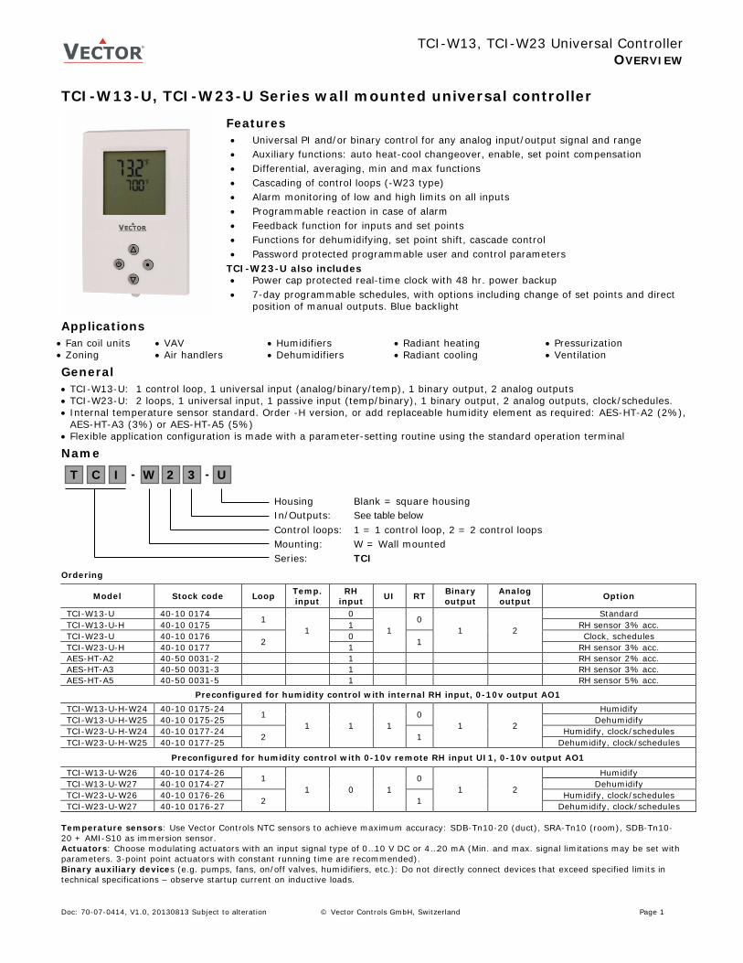
TCI-W13-U, TCI-W23-U Series wall mounted universal controller
Features • Universal PI and/or binary control for any analog input/output signal and range • Auxiliary functions: auto heat-cool changeover, enable, set point compensation • Differential, averaging, min and max functions • Cascading of control loops (-W23 type) • Alarm monitoring of low and high limits on all inputs • Programmable reaction in case of alarm • Feedback function for inputs and set points • Functions for dehumidifying, set point shift, cascade control • Password protected programmable user and control parameters
TCI-W23-U also includes • Power cap protected real-time clock with 48 hr. power backup • 7-day programmable schedules, with options including change of set points and direct
position of manual outputs. Blue backlight
Applications • Fan coil units • Zoning
• VAV • Air handlers
• Humidifiers • Dehumidifiers
• Radiant heating • Radiant cooling
• Pressurization • Ventilation
General • TCI-W13-U: 1 control loop, 1 universal input (analog/binary/temp), 1 binary output, 2 analog outputs • TCI-W23-U: 2 loops, 1 universal input, 1 passive input (temp/binary), 1 binary output, 2 analog outputs, clock/schedules. • Internal temperature sensor standard. Order -H version, or add replaceable humidity element as required: AES-HT-A2 (2%),
AES-HT-A3 (3%) or AES-HT-A5 (5%) • Flexible application configuration is made with a parameter-setting routine using the standard operation terminal
Name
Ordering
Model Stock code Loop Temp. input
RH input UI RT Binary
output Analog output Option
TCI-W13-U 40-10 0174 1 1
0
1 0
1 2
Standard TCI-W13-U-H 40-10 0175 1 RH sensor 3% acc. TCI-W23-U 40-10 0176 2 0 1 Clock, schedules TCI-W23-U-H 40-10 0177 1 RH sensor 3% acc. AES-HT-A2 40-50 0031-2 1 RH sensor 2% acc. AES-HT-A3 40-50 0031-3 1 RH sensor 3% acc. AES-HT-A5 40-50 0031-5 1 RH sensor 5% acc.
Preconfigured for humidity control with internal RH input, 0-10v output AO1 TCI-W13-U-H-W24 40-10 0175-24 1
1 1 1 0
1 2
Humidify TCI-W13-U-H-W25 40-10 0175-25 Dehumidify TCI-W23-U-H-W24 40-10 0177-24 2 1 Humidify, clock/schedules TCI-W23-U-H-W25 40-10 0177-25 Dehumidify, clock/schedules
Preconfigured for humidity control with 0-10v remote RH input UI1, 0-10v output AO1
TCI-W13-U-W26 40-10 0174-26 1 1 0 1
0 1 2
Humidify TCI-W13-U-W27 40-10 0174-27 Dehumidify TCI-W23-U-W26 40-10 0176-26 2 1 Humidify, clock/schedules TCI-W23-U-W27 40-10 0176-27 Dehumidify, clock/schedules
Temperature sensors: Use Vector Controls NTC sensors to achieve maximum accuracy: SDB-Tn10-20 (duct), SRA-Tn10 (room), SDB-Tn10-20 + AMI-S10 as immersion sensor. Actuators: Choose modulating actuators with an input signal type of 0…10 V DC or 4…20 mA (Min. and max. signal limitations may be set with parameters. 3-point point actuators with constant running time are recommended). Binary auxiliary devices (e.g. pumps, fans, on/off valves, humidifiers, etc.): Do not directly connect devices that exceed specified limits in technical specifications – observe startup current on inductive loads.
Housing Blank = square housing In/Outputs: See table below Control loops: 1 = 1 control loop, 2 = 2 control loops Mounting: W = Wall mounted Series: TCI
T C I 2 - W U - 3
Doc: 70-07-0414, V1.0, 20130813 Subject to alteration © Vector Controls GmbH, Switzerland Page 1
TCI-W13, TCI-W23 Universal Controller
OPERATION
Technical specifications Warning! This device is intended to be used for comfort applications. Where a device failure endangers human life and/or property, it is the responsibility of the owner, designer and installer to add additional safety devices to prevent or detect a system failure caused by such a device failure. The manufacturer of this device cannot be held liable for any damage caused by such a failure. Failure to follow specifications, local regulations may endanger life, cause equipment damage, void warranty. Power supply Power requirements 24 VAC ±10%, 50/60 Hz, Class 2, 2.0 A, 48 VA max.
24 VDC ±10% Power consumption max. 3 VA Electrical connection Terminal Connectors
0.34…2.5 mm2 wire (AWG 22…13)
Clock backup min. 48 hours Signal inputs Universal input
Input signal Resolution Impedance
Setting for voltage or current 0…10 V or 0…20 mA 9.76 mV or 0.019 mA (10 bit) Voltage: 98 kΩ Current: 240 Ω
Universal input Input configured to remote temperature (RT) or digital input (DI) Range NTC (Sxx-Tn10 sensor): -40…140 °C (-40…284 °F) Accuracy -40…0 °C (-40…32 °F): 0.5 K
0…50 °C (32…122 °F): 0.2 K 50…100 °C (122…212 °F): 0.5 K > 100 °C (> 212 °F): 1 K
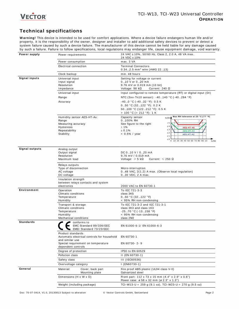
Humidity sensor AES-HT-Ax: Range Measuring accuracy Hysteresis Repeatability Stability
Capacity sensor 0…100% RH See figure to the right ± 1% ± 0.1% < 0.5% / year
Signal outputs Analog output Output signal Resolution Maximum load
DC 0…10 V / 0…20 mA 9.76 mV / 0.019 mA Voltage: ≥ 5 kΩ Current: ≤ 250 Ω
Relays outputs Type of disconnection AC voltage DC voltage
Micro-interruption 0…48 VAC, 2(1.2) A max. (Observe local regulation) 0…30 VDC, 2 A max.
Insulation strength between relays contacts and system electronics
2000 VAC to EN 60730-1
Environment Operation Climatic conditions Temperature Humidity
To IEC 721-3-3 class 3K5 0…50 °C (32…122 °F) < 95% RH non-condensing
Transport & storage Climatic conditions Temperature Humidity Mechanical conditions
To IEC 721-3-2 and IEC 721-3-1 class 3K3 and class 1K3 -25…70 °C (-13…158 °F) < 95% RH non-condensing class 2M2
Standards conforms to EMC Standard 89/336/EEC EMEI Standard 73/23/EEC
EN 61000-6-1/ EN 61000-6-3
Product standards Automatic electrical controls for household and similar use Special requirement on temperature dependent controls
EN 60730-1 EN 60730- 2- 9
Degree of protection IP30 to EN 60529 Pollution class II (EN 60730-1) Safety class III (IEC60536) Overvoltage category I (EN60730-1) General Material: Cover, back part
Mounting plate Fire proof ABS plastic (UL94 class V-0) Galvanized steel
Dimensions (H x W x D) Front part: 112 x 73 x 15 mm (4.4” x 2.9” x 0.6”) Power case: ø 58 x 32 mm (ø 2.3” x 1.3”)
Weight (including package) TCI-W13-U = 259 g (9.1 oz), TCI-W23-U = 270 g (9.5 oz)
Max RH tolerance at 25 °C (77 °F)
%RH
%RH
10 20 30 40 10
90 0 50 60 70 80
±1 ±0
±2 ±3 ±4 ±5
AES-HT-A2
AES-HT-A3 AES-HT-A5
Doc: 70-07-0414, V1.0, 20130813 Subject to alteration © Vector Controls GmbH, Switzerland Page 2
TCI-W13, TCI-W23 Universal Controller
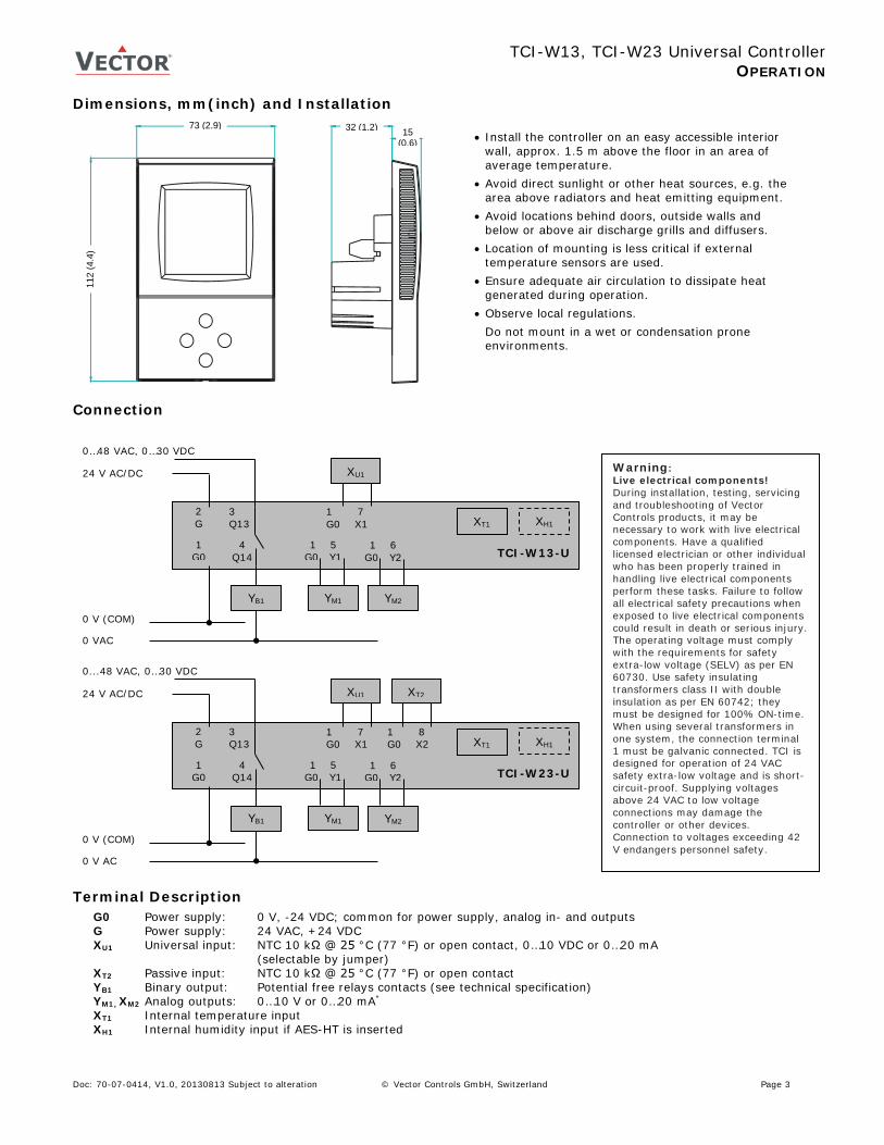
OPERATION Dimensions, mm(inch) and Installation
Connection
Terminal Description
G0 Power supply: 0 V, -24 VDC; common for power supply, analog in- and outputs G Power supply: 24 VAC, +24 VDC XU1 Universal input: NTC 10 kΩ @ 25 °C (77 °F) or open contact, 0…10 VDC or 0…20 mA (selectable by jumper) XT2 Passive input: NTC 10 kΩ @ 25 °C (77 °F) or open contact YB1 Binary output: Potential free relays contacts (see technical specification) YM1, XM2 Analog outputs: 0…10 V or 0…20 mA*
XT1 Internal temperature input XH1 Internal humidity input if AES-HT is inserted
112
(4.4
)
73 (2.9) 32 (1.2) 15 (0.6)
Warning: Live electrical components! During installation, testing, servicing and troubleshooting of Vector Controls products, it may be necessary to work with live electrical components. Have a qualified licensed electrician or other individual who has been properly trained in handling live electrical components perform these tasks. Failure to follow all electrical safety precautions when exposed to live electrical components could result in death or serious injury. The operating voltage must comply with the requirements for safety extra-low voltage (SELV) as per EN 60730. Use safety insulating transformers class II with double insulation as per EN 60742; they must be designed for 100% ON-time. When using several transformers in one system, the connection terminal 1 must be galvanic connected. TCI is designed for operation of 24 VAC safety extra-low voltage and is short-circuit-proof. Supplying voltages above 24 VAC to low voltage connections may damage the controller or other devices. Connection to voltages exceeding 42 V endangers personnel safety.
XH1 XT1
0 V (COM)
24 V AC/DC
2 G
TCI-W13-U 1
G0
0…48 VAC, 0…30 VDC
3 Q13
1 5 G0 Y1
YM1
1 7 G0 X1
XU1
YB1
4 Q14
0 VAC
1 6 G0 Y2
YM2
1 8 G0 X2 XH1 XT1
0 V (COM)
24 V AC/DC
2 G
TCI-W23-U 1
G0
0...48 VAC, 0…30 VDC
3 Q13
1 5 G0 Y1
YM1
1 7 G0 X1
XU1
YB1
4 Q14
0 V AC
XT2
1 6 G0 Y2
YM2
• Install the controller on an easy accessible interior wall, approx. 1.5 m above the floor in an area of average temperature.
• Avoid direct sunlight or other heat sources, e.g. the area above radiators and heat emitting equipment.
• Avoid locations behind doors, outside walls and below or above air discharge grills and diffusers.
• Location of mounting is less critical if external temperature sensors are used.
• Ensure adequate air circulation to dissipate heat generated during operation.
• Observe local regulations. Do not mount in a wet or condensation prone environments.
Doc: 70-07-0414, V1.0, 20130813 Subject to alteration © Vector Controls GmbH, Switzerland Page 3
TCI-W13, TCI-W23 Universal Controller
OPERATION Display and Operation
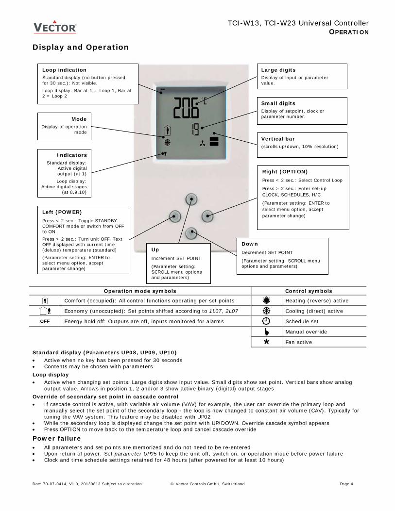
Operation mode symbols Control symbols
Comfort (occupied): All control functions operating per set points Heating (reverse) active
Economy (unoccupied): Set points shifted according to 1L07, 2L07 Cooling (direct) active
OFF Energy hold off: Outputs are off, inputs monitored for alarms Schedule set
Manual override
Fan active
Standard display (Parameters UP08, UP09, UP10) • Active when no key has been pressed for 30 seconds • Contents may be chosen with parameters Loop display • Active when changing set points. Large digits show input value. Small digits show set point. Vertical bars show analog
output value. Arrows in position 1, 2 and/or 3 show active binary (digital) output stages Override of secondary set point in cascade control • If cascade control is active, with variable air volume (VAV) for example, the user can override the primary loop and
manually select the set point of the secondary loop - the loop is now changed to constant air volume (CAV). Typically for tuning the VAV system. This feature may be disabled with UP02
• While the secondary loop is displayed change the set point with UP/DOWN. Override cascade symbol appears • Press OPTION to move back to the temperature loop and cancel cascade override
Power failure • All parameters and set points are memorized and do not need to be re-entered • Upon return of power: Set parameter UP05 to keep the unit off, switch on, or operation mode before power failure • Clock and time schedule settings retained for 48 hours (after powered for at least 10 hours)
Left (POWER) Press < 2 sec.: Toggle STANDBY-COMFORT mode or switch from OFF to ON Press > 2 sec.: Turn unit OFF. Text OFF displayed with current time (deluxe) temperature (standard) (Parameter setting: ENTER to select menu option, accept parameter change)
Up Increment SET POINT
(Parameter setting: SCROLL menu options and parameters)
Down Decrement SET POINT
(Parameter setting: SCROLL menu options and parameters)
Loop indication Standard display (no button pressed for 30 sec.): Not visible. Loop display: Bar at 1 = Loop 1, Bar at 2 = Loop 2
Mode Display of operation
mode
Large digits Display of input or parameter value.
Indicators Standard display:
Active digital output (at 1)
Loop display: Active digital stages
(at 8,9,10)
Vertical bar (scrolls up/down, 10% resolution)
Small digits Display of setpoint, clock or parameter number.
Right (OPTION) Press < 2 sec.: Select Control Loop
Press > 2 sec.: Enter set-up CLOCK, SCHEDULES, H/C
(Parameter setting: ENTER to select menu option, accept parameter change)
Doc: 70-07-0414, V1.0, 20130813 Subject to alteration © Vector Controls GmbH, Switzerland Page 4
TCI-W13, TCI-W23 Universal Controller
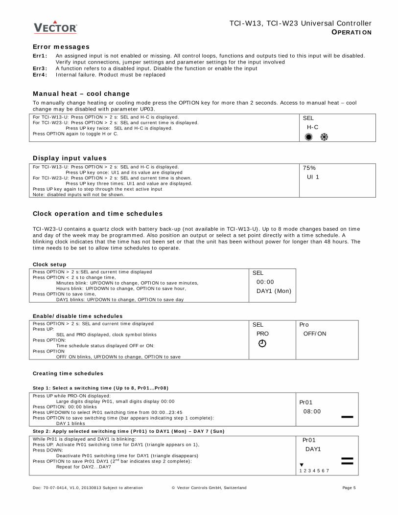
OPERATION Error messages Err1: An assigned input is not enabled or missing. All control loops, functions and outputs tied to this input will be disabled.
Verify input connections, jumper settings and parameter settings for the input involved Err3: A function refers to a disabled input. Disable the function or enable the input Err4: Internal failure. Product must be replaced
Manual heat – cool change To manually change heating or cooling mode press the OPTION key for more than 2 seconds. Access to manual heat – cool change may be disabled with parameter UP03. For TCI-W13-U: Press OPTION > 2 s: SEL and H-C is displayed. For TCI-W23-U: Press OPTION > 2 s: SEL and current time is displayed. Press UP key twice: SEL and H-C is displayed. Press OPTION again to toggle H or C.
SEL H-C
Display input values For TCI-W13-U: Press OPTION > 2 s: SEL and H-C is displayed. Press UP key once: UI1 and its value are displayed For TCI-W23-U: Press OPTION > 2 s: SEL and current time is shown. Press UP key three times: UI1 and value are displayed. Press UP key again to step through the next active input Note: disabled inputs will not be shown.
75% UI 1
Clock operation and time schedules TCI-W23-U contains a quartz clock with battery back-up (not available in TCI-W13-U). Up to 8 mode changes based on time and day of the week may be programmed. Also position an output or select a set point directly with a time schedule. A blinking clock indicates that the time has not been set or that the unit has been without power for longer than 48 hours. The time needs to be set to allow time schedules to operate. Clock setup Press OPTION > 2 s:SEL and current time displayed Press OPTION < 2 s to change time,
Minutes blink: UP/DOWN to change, OPTION to save minutes, Hours blink: UP/DOWN to change, OPTION to save hour,
Press OPTION to save time, DAY1 blinks: UP/DOWN to change, OPTION to save day
SEL 00:00 DAY1 (Mon)
Enable/disable time schedules Press OPTION > 2 s: SEL and current time displayed Press UP:
SEL and PRO displayed, clock symbol blinks Press OPTION:
Time schedule status displayed OFF or ON: Press OPTION
OFF/ ON blinks, UP/DOWN to change, OPTION to save
SEL PRO
Pro OFF/ON
Creating time schedules Step 1: Select a switching time (Up to 8, Pr01...Pr08)
Press UP while PRO-ON displayed: Large digits display Pr01, small digits display 00:00
Press OPTION: 00:00 blinks Press UP/DOWN to select Pr01 switching time from 00:00…23:45 Press OPTION to save switching time (bar appears indicating step 1 complete):
DAY 1 blinks
Pr01 08:00
Step 2: Apply selected switching time (Pr01) to DAY1 (Mon) – DAY 7 (Sun)
While Pr01 is displayed and DAY1 is blinking: Press UP: Activate Pr01 switching time for DAY1 (triangle appears on 1), Press DOWN: Deactivate Pr01 switching time for DAY1 (triangle disappears) Press OPTION to save Pr01 DAY1 (2nd bar indicates step 2 complete):
Repeat for DAY2...DAY7
Pr01 DAY1 1 2 3 4 5 6 7
Doc: 70-07-0414, V1.0, 20130813 Subject to alteration © Vector Controls GmbH, Switzerland Page 5

TCI-W13, TCI-W23 Universal Controller
OPERATION Step 3: Select action for switching time (Pr01+Days)
After Pro1, DAY1…DAY7 is completed (Pro1 switching time activate or deactivate on desired days), press OPTION again to come to desired action for Pro1. The following options appear in order:
No = switching time not active OP = operation mode (select ON (Comfort/Occupied), ECO (Economy/Unoccupied), OFF) L1 = set point of loop 1 (select set point) L2 = set point of loop 2 (select set point) d1 = ON/OFF status of do1 (output must be in manual mode) d2 = ON/OFF status of do2 (output must be in manual mode) A1 = set point (0…100%) of ao1 (output must be in manual mode)
After repeatedly pressing OPTION through DAY7: First available action No appears, blinking:
Press UP/DOWN to scroll through the 8 possible actions (3nd bar indicates step 3 complete)
Pr01 no
Step 4: Complete switching event (e.g. Pro1 = 08:00, DAY 1, Comfort mode)
Available actions blink as you scroll through them, Press OPTION to select one: Characteristics of action (e.g. 0…100% for A1) appear (4th bar indicates step 4 complete)
Press UP/DOWN to select, OPTION to complete
Pr01 08:00
Doc: 70-07-0414, V1.0, 20130813 Subject to alteration © Vector Controls GmbH, Switzerland Page 6
TCI-W13, TCI-W23 Universal Controller
SETUP AND CONFIGURATION
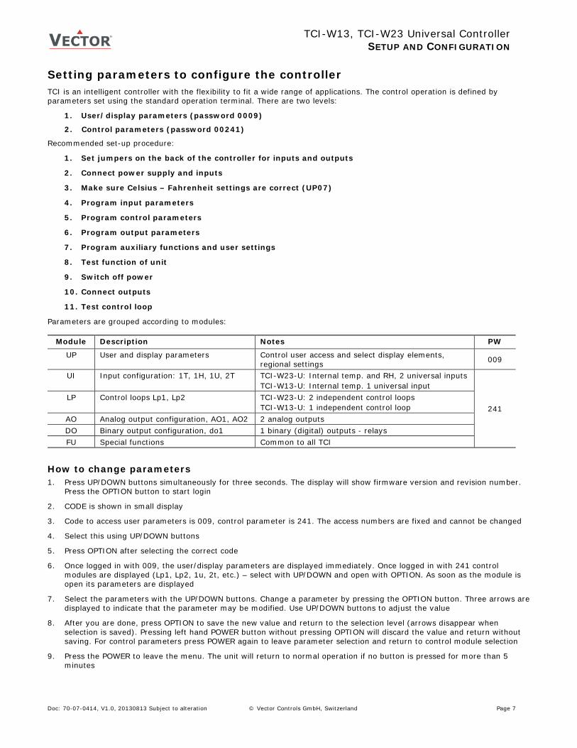
Setting parameters to configure the controller TCI is an intelligent controller with the flexibility to fit a wide range of applications. The control operation is defined by parameters set using the standard operation terminal. There are two levels:
1. User/display parameters (password 0009)
2. Control parameters (password 00241)
Recommended set-up procedure:
1. Set jumpers on the back of the controller for inputs and outputs
2. Connect power supply and inputs
3. Make sure Celsius – Fahrenheit settings are correct (UP07)
4. Program input parameters
5. Program control parameters
6. Program output parameters
7. Program auxiliary functions and user settings
8. Test function of unit
9. Switch off power
10. Connect outputs
11. Test control loop
Parameters are grouped according to modules:
Module Description Notes PW
UP User and display parameters Control user access and select display elements, regional settings 009
UI Input configuration: 1T, 1H, 1U, 2T TCI-W23-U: Internal temp. and RH, 2 universal inputs TCI-W13-U: Internal temp. 1 universal input
241 LP Control loops Lp1, Lp2 TCI-W23-U: 2 independent control loops
TCI-W13-U: 1 independent control loop AO Analog output configuration, AO1, AO2 2 analog outputs DO Binary output configuration, do1 1 binary (digital) outputs - relays FU Special functions Common to all TCI
How to change parameters 1. Press UP/DOWN buttons simultaneously for three seconds. The display will show firmware version and revision number.
Press the OPTION button to start login
2. CODE is shown in small display
3. Code to access user parameters is 009, control parameter is 241. The access numbers are fixed and cannot be changed
4. Select this using UP/DOWN buttons
5. Press OPTION after selecting the correct code
6. Once logged in with 009, the user/display parameters are displayed immediately. Once logged in with 241 control modules are displayed (Lp1, Lp2, 1u, 2t, etc.) – select with UP/DOWN and open with OPTION. As soon as the module is open its parameters are displayed
7. Select the parameters with the UP/DOWN buttons. Change a parameter by pressing the OPTION button. Three arrows are displayed to indicate that the parameter may be modified. Use UP/DOWN buttons to adjust the value
8. After you are done, press OPTION to save the new value and return to the selection level (arrows disappear when selection is saved). Pressing left hand POWER button without pressing OPTION will discard the value and return without saving. For control parameters press POWER again to leave parameter selection and return to control module selection
9. Press the POWER to leave the menu. The unit will return to normal operation if no button is pressed for more than 5 minutes
Doc: 70-07-0414, V1.0, 20130813 Subject to alteration © Vector Controls GmbH, Switzerland Page 7
TCI-W13, TCI-W23 Universal Controller
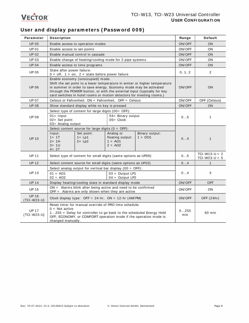
USER CONFIGURATION User and display parameters (Password 009)
Parameter Description Range Default
UP 00 Enable access to operation modes ON/OFF ON UP 01 Enable access to set points ON/OFF ON UP 02 Enable manual control in cascade ON/OFF ON UP 03 Enable change of heating/cooling mode for 2 pipe systems ON/OFF ON UP 04 Enable access to time programs ON/OFF ON
UP 05 State after power failure: 0 = off, 1 = on, 2 = state before power failure 0, 1, 2 2
UP 06
Enable economy (unoccupied) mode. Shift the set point to a lower temperature in winter or higher temperature in summer in order to save energy. Economy mode may be activated through the POWER button, or with the external input (typically for key card switches in hotel rooms or motion detectors for meeting rooms.)
ON/OFF ON
UP 07 Celsius or Fahrenheit: ON = Fahrenheit, OFF = Celsius ON/OFF OFF (Celsius) UP 08 Show standard display while no key is pressed ON/OFF ON
UP 09
Select type of content for large digits (00= OFF):
0...5 1 01= Input 02= Set point 03= Analog output
04= Binary output 05= Clock
UP 10
Select content source for large digits (0 = OFF):
0...4 1 Input: 1= 1T 2= 1H 3= 1U 4= 2T
Set point: 1= Lp1 2= Lp2
Analog or floating output: 1 = AO1 2 = AO2
Binary output: 1 = DO1
UP 11 Select type of content for small digits (same options as UP09) 0...5 TCI-W13-U = 2 TCI-W23-U = 5
UP 12 Select content source for small digits (same options as UP10) 0...4 1
UP 13 Select analog output for vertical bar display (00 = OFF):
0...4 3 01 = AO1 02 = AO2
03 = Output LP1 04 = Output LP2
UP 14 Display heating/cooling state in standard display mode ON/OFF OFF
UP 15 ON = Alarms blink after being active and need to be confirmed OFF = Alarms are only shown when they are active ON/OFF ON
UP 16 (TCI-W23-U) Clock display type: OFF = 24-hr, ON = 12-hr (AM/PM) ON/OFF OFF (24hr)
UP 17 (TCI-W23-U)
Reset timer for manual override of PRO time schedule: 0 = Not active 1...255 = Delay for controller to go back to the scheduled Energy Hold OFF, ECONOMY, or COMFORT operation mode if the operation mode is changed manually.
0...255 min 60 min
Doc: 70-07-0414, V1.0, 20130813 Subject to alteration © Vector Controls GmbH, Switzerland Page 8
TCI-W13, TCI-W23 Universal Controller
INPUT CONFIGURATION
Control configuration (Password 241) Input configuration Internal inputs 1T temperature, 1H humidity for –H devices or with AES-HT inserted
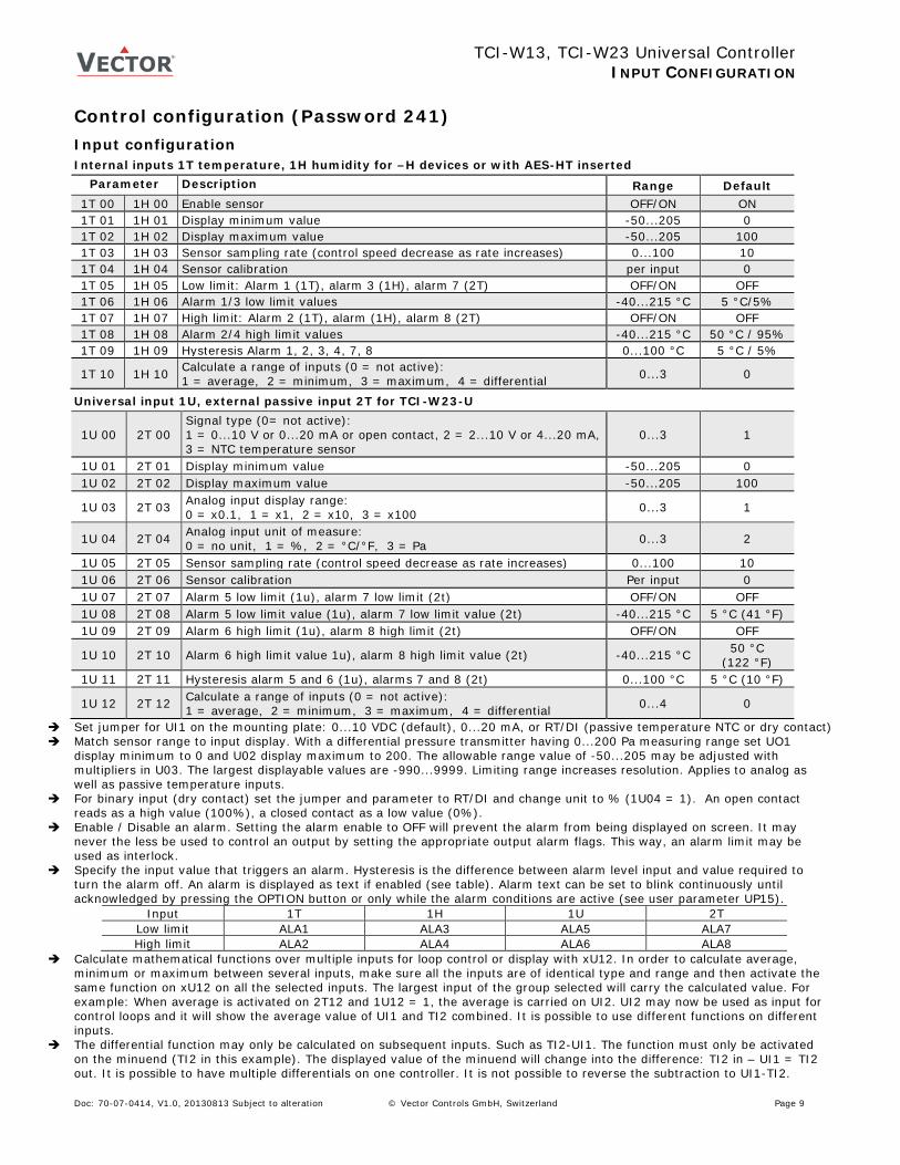
Parameter Description Range Default 1T 00 1H 00 Enable sensor OFF/ON ON 1T 01 1H 01 Display minimum value -50...205 0 1T 02 1H 02 Display maximum value -50...205 100 1T 03 1H 03 Sensor sampling rate (control speed decrease as rate increases) 0...100 10 1T 04 1H 04 Sensor calibration per input 0 1T 05 1H 05 Low limit: Alarm 1 (1T), alarm 3 (1H), alarm 7 (2T) OFF/ON OFF 1T 06 1H 06 Alarm 1/3 low limit values -40...215 °C 5 °C/5% 1T 07 1H 07 High limit: Alarm 2 (1T), alarm (1H), alarm 8 (2T) OFF/ON OFF 1T 08 1H 08 Alarm 2/4 high limit values -40...215 °C 50 °C / 95% 1T 09 1H 09 Hysteresis Alarm 1, 2, 3, 4, 7, 8 0...100 °C 5 °C / 5%
1T 10 1H 10 Calculate a range of inputs (0 = not active): 1 = average, 2 = minimum, 3 = maximum, 4 = differential 0...3 0
Universal input 1U, external passive input 2T for TCI-W23-U
1U 00 2T 00 Signal type (0= not active): 1 = 0...10 V or 0...20 mA or open contact, 2 = 2...10 V or 4...20 mA, 3 = NTC temperature sensor
0...3 1
1U 01 2T 01 Display minimum value -50...205 0 1U 02 2T 02 Display maximum value -50...205 100
1U 03 2T 03 Analog input display range: 0 = x0.1, 1 = x1, 2 = x10, 3 = x100 0...3 1
1U 04 2T 04 Analog input unit of measure: 0 = no unit, 1 = %, 2 = °C/°F, 3 = Pa 0...3 2
1U 05 2T 05 Sensor sampling rate (control speed decrease as rate increases) 0...100 10 1U 06 2T 06 Sensor calibration Per input 0 1U 07 2T 07 Alarm 5 low limit (1u), alarm 7 low limit (2t) OFF/ON OFF 1U 08 2T 08 Alarm 5 low limit value (1u), alarm 7 low limit value (2t) -40...215 °C 5 °C (41 °F) 1U 09 2T 09 Alarm 6 high limit (1u), alarm 8 high limit (2t) OFF/ON OFF
1U 10 2T 10 Alarm 6 high limit value 1u), alarm 8 high limit value (2t) -40...215 °C 50 °C (122 °F)
1U 11 2T 11 Hysteresis alarm 5 and 6 (1u), alarms 7 and 8 (2t) 0...100 °C 5 °C (10 °F)
1U 12 2T 12 Calculate a range of inputs (0 = not active): 1 = average, 2 = minimum, 3 = maximum, 4 = differential 0...4 0
Set jumper for UI1 on the mounting plate: 0...10 VDC (default), 0...20 mA, or RT/DI (passive temperature NTC or dry contact) Match sensor range to input display. With a differential pressure transmitter having 0...200 Pa measuring range set UO1
display minimum to 0 and U02 display maximum to 200. The allowable range value of -50...205 may be adjusted with multipliers in U03. The largest displayable values are -990...9999. Limiting range increases resolution. Applies to analog as well as passive temperature inputs.
For binary input (dry contact) set the jumper and parameter to RT/DI and change unit to % (1U04 = 1). An open contact reads as a high value (100%), a closed contact as a low value (0%).
Enable / Disable an alarm. Setting the alarm enable to OFF will prevent the alarm from being displayed on screen. It may never the less be used to control an output by setting the appropriate output alarm flags. This way, an alarm limit may be used as interlock.
Specify the input value that triggers an alarm. Hysteresis is the difference between alarm level input and value required to turn the alarm off. An alarm is displayed as text if enabled (see table). Alarm text can be set to blink continuously until acknowledged by pressing the OPTION button or only while the alarm conditions are active (see user parameter UP15).
Calculate mathematical functions over multiple inputs for loop control or display with xU12. In order to calculate average, minimum or maximum between several inputs, make sure all the inputs are of identical type and range and then activate the same function on xU12 on all the selected inputs. The largest input of the group selected will carry the calculated value. For example: When average is activated on 2T12 and 1U12 = 1, the average is carried on UI2. UI2 may now be used as input for control loops and it will show the average value of UI1 and TI2 combined. It is possible to use different functions on different inputs.
The differential function may only be calculated on subsequent inputs. Such as TI2-UI1. The function must only be activated on the minuend (TI2 in this example). The displayed value of the minuend will change into the difference: TI2 in – UI1 = TI2 out. It is possible to have multiple differentials on one controller. It is not possible to reverse the subtraction to UI1-TI2.
Input 1T 1H 1U 2T Low limit ALA1 ALA3 ALA5 ALA7 High limit ALA2 ALA4 ALA6 ALA8
Doc: 70-07-0414, V1.0, 20130813 Subject to alteration © Vector Controls GmbH, Switzerland Page 9
TCI-W13, TCI-W23 Universal Controller
CONTROL LOOP CONFIGURATION
Control loop configuration Manipulation of the set point (1L and 2L)
Parameter Description Range Default
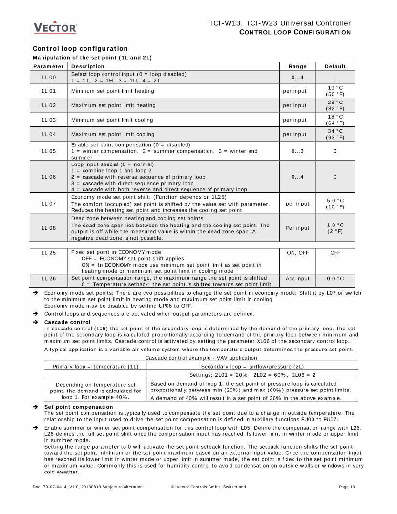
1L 00 Select loop control input (0 = loop disabled): 1 = 1T, 2 = 1H, 3 = 1U, 4 = 2T 0...4 1
1L 01 Minimum set point limit heating per input 10 °C (50 °F)
1L 02 Maximum set point limit heating per input 28 °C (82 °F)
1L 03 Minimum set point limit cooling per input 18 °C (64 °F)
1L 04 Maximum set point limit cooling per input 34 °C (93 °F)
1L 05 Enable set point compensation (0 = disabled) 1 = winter compensation, 2 = summer compensation, 3 = winter and summer
0...3 0
1L 06
Loop input special (0 = normal): 1 = combine loop 1 and loop 2 2 = cascade with reverse sequence of primary loop 3 = cascade with direct sequence primary loop 4 = cascade with both reverse and direct sequence of primary loop
0...4 0
1L 07 Economy mode set point shift: (Function depends on 1L25) The comfort (occupied) set point is shifted by the value set with parameter. Reduces the heating set point and increases the cooling set point.
per input 5.0 °C (10 °F)
1L 08
Dead zone between heating and cooling set points The dead zone span lies between the heating and the cooling set point. The output is off while the measured value is within the dead zone span. A negative dead zone is not possible.
Per input 1.0 °C (2 °F)
1L 25 Fixed set point in ECONOMY mode
OFF = ECONOMY set point shift applies ON = In ECONOMY mode use minimum set point limit as set point in heating mode or maximum set point limit in cooling mode
ON, OFF OFF
1L 26 Set point compensation range, the maximum range the set point is shifted. 0 = Temperature setback: the set point is shifted towards set point limit
Acc input 0.0 °C
Economy mode set points: There are two possibilities to change the set point in economy mode: Shift it by L07 or switch to the minimum set point limit in heating mode and maximum set point limit in cooling. Economy mode may be disabled by setting UP06 to OFF.
Control loops and sequences are activated when output parameters are defined. Cascade control
In cascade control (L06) the set point of the secondary loop is determined by the demand of the primary loop. The set point of the secondary loop is calculated proportionally according to demand of the primary loop between minimum and maximum set point limits. Cascade control is activated by setting the parameter XL06 of the secondary control loop. A typical application is a variable air volume system where the temperature output determines the pressure set point.
Cascade control example - VAV application Primary loop = temperature (1L) Secondary loop = airflow/pressure (2L)
Settings: 2L01 = 20%, 2L02 = 60%, 2L06 = 2
Depending on temperature set point, the demand is calculated for
loop 1. For example 40%.
Based on demand of loop 1, the set point of pressure loop is calculated proportionally between min (20%) and max (60%) pressure set point limits. A demand of 40% will result in a set point of 36% in the above example.
Set point compensation The set point compensation is typically used to compensate the set point due to a change in outside temperature. The relationship to the input used to drive the set point compensation is defined in auxiliary functions FU00 to FU07.
Enable summer or winter set point compensation for this control loop with L05. Define the compensation range with L26. L26 defines the full set point shift once the compensation input has reached its lower limit in winter mode or upper limit in summer mode. Setting the range parameter to 0 will activate the set point setback function: The setback function shifts the set point toward the set point minimum or the set point maximum based on an external input value. Once the compensation input has reached its lower limit in winter mode or upper limit in summer mode, the set point is fixed to the set point minimum or maximum value. Commonly this is used for humidity control to avoid condensation on outside walls or windows in very cold weather.
Doc: 70-07-0414, V1.0, 20130813 Subject to alteration © Vector Controls GmbH, Switzerland Page 10

TCI-W13, TCI-W23 Universal Controller
CONTROL LOOP CONFIGURATION
Legend T, U Input signal temp/universal XPH P-band heating/direct XPC P-band cooling/reverse XDZ Dead zone h/c set points XSBY Economy mode set point shift WH Set point heating/reverse WC Set point cooling/direct YH1, YR1 PI sequence heating/reverse YC1, YD1 PI sequence cooling/direct
PI control sequence Parameter Description Range Default
1L 09 Offset for heating PI sequence per input 0 1L 10 Offset for cooling PI sequence per input 0
1L 11 P-band heating per input 2.0 °C (4.0 °F)
1L 12 P-band cooling per input 2.0 °C (4.0 °F)
1L 13 Integral gain heating (0.1 steps) Low = slow reaction, high = fast reaction 0...25.5 0.0
1L 14 Integral gain cooling (0.1 steps) 0...25.5 0.0
1L 15 Measuring interval integral (seconds) Low = fast reaction, high value = slow reaction 0...255 s 1 s
Proportional control (P-band)
The proportional control function calculates the output based on the difference between set point and measured value. The proportional band (P-band) defines the difference between set point and measured value which will result in a 100% output. For example, with a heating or reverse 0...10 V control sequence, and a 2.0 °C (4.0 °F) P-band value, at 10 V the controller will be 2.0 °C (4.0 °F) below set point. This is the working range of the proportional control sequence.
Setting the proportional band to 0 disables proportional control.
Integral and differential control
Proportional control is in most cases a very stable control mode. The flaw of proportional control alone, however, is that the set point is normally not reached. As the measured value gets closer to the set point, the output reduces until it reaches a point, a fraction above or below the set point, where the output equals the load. To reach the set point and achieve a higher level in comfort the integral/differential function should be activated.
Integral gain (KI) dynamically increases the output by the selected KI value every Measuring interval TI until the set point is reached. The challenge is to prevent hunting, where the output increases too fast, the temperature overshoots the set point, the output goes to 0, the temperature undershoots the set point, and the cycle repeats itself. Hunting may result if the integral gain is too high or measuring interval too short. Each system is different. To prevent instability the P-band should be extended when integral gain is active (L14 or L15 set above 0).
Setting the integral gain to 0 disables integral and differential control.
Recommended values heating (air) heating (radiant) humidifying cooling dehumidifying pressure
P-band 2...3 °C (4...6 °F) 1...1.5 °C (2...3°F) Measuring interval (TI) 2 5 15 1 70 1
Integral gain (KI) 0.2 0.1 0.1 0.2 0.3 0.8
Heating/Reverse Cooling/Direct
100
0 T [°C, °F] U [V, mA]
YH1, YR1
XPH
WH
XPC XDZ
YC1, YD1
WC
XSBY XSBY
Doc: 70-07-0414, V1.0, 20130813 Subject to alteration © Vector Controls GmbH, Switzerland Page 11
TCI-W13, TCI-W23 Universal Controller
CONTROL LOOP CONFIGURATION
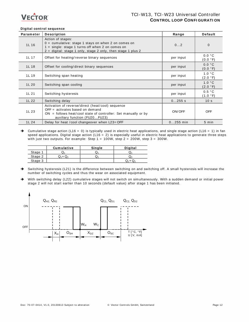
Legend T, U Input signal OQH Offset heating/direct OQC Offset cooling/reverse XDZ Dead zone XSBY Economy set point shift WH Set point heating/reverse WC Set point cooling/direct QC, QD Binary sequences cooling/direct QH, QR Binary sequences heating/reverse
Digital control sequence Parameter Description Range Default
1L 16
Action of stages: 0 = cumulative: stage 1 stays on when 2 on comes on 1 = single: stage 1 turns off when 2 on comes on 2 = digital: stage 1 only, stage 2 only, then stage 1 plus 2
0...2 0
1L 17 Offset for heating/reverse binary sequences per input 0.0 °C (0.0 °F)
1L 18 Offset for cooling/direct binary sequences per input 0.0 °C (0.0 °F)
1L 19 Switching span heating per input 1.0 °C (2.0 °F)
1L 20 Switching span cooling per input 1.0 °C (2.0 °F)
1L 21 Switching hysteresis per input 0.5 °C (1.0 °F)
1L 22 Switching delay 0...255 s 10 s
1L 23
Activation of reverse/direct (heat/cool) sequence OFF = activates based on demand ON = follows heat/cool state of controller: Set manually or by
auxiliary function (FU20...FU23)
ON/OFF OFF
1L 24 Delay for heat /cool changeover when L23=OFF 0...255 min 5 min Cumulative stage action (L16 = 0) is typically used in electric heat applications, and single stage action (L16 = 1) in fan
speed applications. Digital stage action (L16 = 2) is especially useful in electric heat applications to generate three steps with just two outputs. For example: Step 1 = 100W, step 2 = 200W, step 3 = 300W.
Switching hysteresis (L21) is the difference between switching on and switching off. A small hysteresis will increase the number of switching cycles and thus the wear on associated equipment.
With switching delay (L22) cumulative stages will not switch on simultaneously. With a sudden demand or initial power stage 2 will not start earlier than 10 seconds (default value) after stage 1 has been initiated.
Cumulative Single Digital Stage 1 Q1 Q1 Q1 Stage 2 Q1+Q2 Q2 Q2 Stage 3 Q1+Q2
ON
OFF
T [°C, °F] U [V, mA]
QC2, QD2
OSH
WH
OSC XDZ
WC
XH
QC1, QD1 QH2, QR2
Doc: 70-07-0414, V1.0, 20130813 Subject to alteration © Vector Controls GmbH, Switzerland Page 12
TCI-W13, TCI-W23 Universal Controller
OUTPUT CONFIGURATION
WH WC
YH1,YR1
XDZ
YC1,YD1 Heating
Cooling
1A04 1A05 1A03
1A06
T (°C/F), U(V, mA)
100%
50%
0%
Output priority 1. Alarm level low 2. Alarm level high 3. Operation mode OFF 4. Control function
Output configuration Analog output configuration (1A, 2A) Parameter Description Range Default
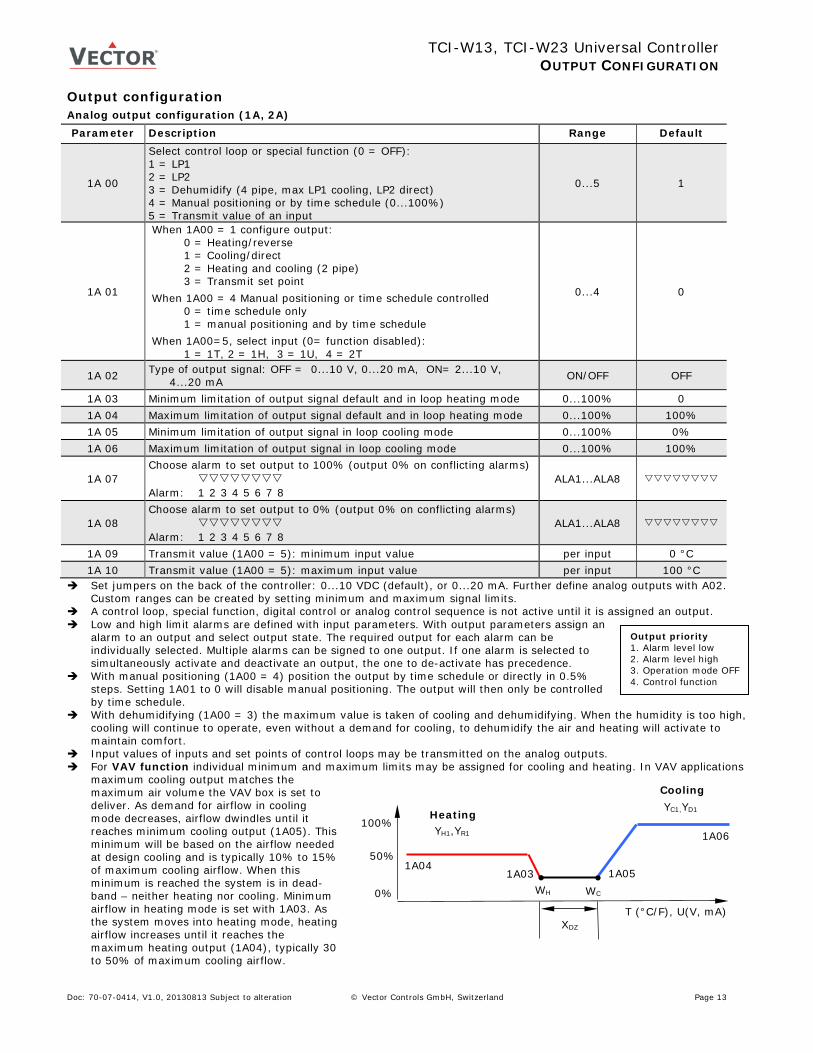
1A 00
Select control loop or special function (0 = OFF): 1 = LP1 2 = LP2 3 = Dehumidify (4 pipe, max LP1 cooling, LP2 direct) 4 = Manual positioning or by time schedule (0...100%) 5 = Transmit value of an input
0...5 1
1A 01
When 1A00 = 1 configure output: 0 = Heating/reverse 1 = Cooling/direct
2 = Heating and cooling (2 pipe)
3 = Transmit set point When 1A00 = 4 Manual positioning or time schedule controlled
0 = time schedule only 1 = manual positioning and by time schedule
When 1A00=5, select input (0= function disabled): 1 = 1T, 2 = 1H, 3 = 1U, 4 = 2T
0...4 0
1A 02 Type of output signal: OFF = 0...10 V, 0...20 mA, ON= 2...10 V, 4...20 mA ON/OFF OFF
1A 03 Minimum limitation of output signal default and in loop heating mode 0...100% 0 1A 04 Maximum limitation of output signal default and in loop heating mode 0...100% 100% 1A 05 Minimum limitation of output signal in loop cooling mode 0...100% 0% 1A 06 Maximum limitation of output signal in loop cooling mode 0...100% 100%
1A 07 Choose alarm to set output to 100% (output 0% on conflicting alarms) Alarm: 1 2 3 4 5 6 7 8
ALA1...ALA8
1A 08 Choose alarm to set output to 0% (output 0% on conflicting alarms) Alarm: 1 2 3 4 5 6 7 8
ALA1...ALA8
1A 09 Transmit value (1A00 = 5): minimum input value per input 0 °C 1A 10 Transmit value (1A00 = 5): maximum input value per input 100 °C
Set jumpers on the back of the controller: 0...10 VDC (default), or 0...20 mA. Further define analog outputs with A02. Custom ranges can be created by setting minimum and maximum signal limits.
A control loop, special function, digital control or analog control sequence is not active until it is assigned an output. Low and high limit alarms are defined with input parameters. With output parameters assign an
alarm to an output and select output state. The required output for each alarm can be individually selected. Multiple alarms can be signed to one output. If one alarm is selected to simultaneously activate and deactivate an output, the one to de-activate has precedence.
With manual positioning (1A00 = 4) position the output by time schedule or directly in 0.5% steps. Setting 1A01 to 0 will disable manual positioning. The output will then only be controlled by time schedule.
With dehumidifying (1A00 = 3) the maximum value is taken of cooling and dehumidifying. When the humidity is too high, cooling will continue to operate, even without a demand for cooling, to dehumidify the air and heating will activate to maintain comfort.
Input values of inputs and set points of control loops may be transmitted on the analog outputs. For VAV function individual minimum and maximum limits may be assigned for cooling and heating. In VAV applications
maximum cooling output matches the maximum air volume the VAV box is set to deliver. As demand for airflow in cooling mode decreases, airflow dwindles until it reaches minimum cooling output (1A05). This minimum will be based on the airflow needed at design cooling and is typically 10% to 15% of maximum cooling airflow. When this minimum is reached the system is in dead-band – neither heating nor cooling. Minimum airflow in heating mode is set with 1A03. As the system moves into heating mode, heating airflow increases until it reaches the maximum heating output (1A04), typically 30 to 50% of maximum cooling airflow.
Doc: 70-07-0414, V1.0, 20130813 Subject to alteration © Vector Controls GmbH, Switzerland Page 13
TCI-W13, TCI-W23 Universal Controller
OUTPUT CONFIGURATION
Output priority 1. Alarm level low 2. Alarm level high 3. Operation mode OFF 4. Control function
Digital output configuration (1d) Parameter Description Range Default
1d 00 Enable digital or PWM output OFF = 1d is a digital output ON = 1d is a PWM output
ON/OFF OFF
1d 01
Select control loop or special function (0 = OFF) 1 = LP1, 2 = LP2 3 = Dehumidify (4 pipe, max LP1 cooling, LP2 direct) 4 = Manual positioning (on/off) 5 = State functions
0...5 0
1d 02
When 1d01 = 1, configure output: 0 = Stage 1 heating/reverse
1 = Stage 1 cooling/direct
2 = Stage 1 heating and cooling, reverse and direct
3 = Stage 2 heating/reverse
4 = Stage 2 cooling/direct
5 = Stage 2 heating and cooling, reverse and direct
If 1d01 = 4 Manual positioning or time schedule controlled 0 = Time schedule controlled only 1 = Manual positioning and time schedule controlled
When 1d01=5, select state functions: 0 = ON if controller operation state is ON 1 = ON while demand on any output 2 = ON while controller in heating mode and operation state ON 3 = ON while controller in cooling mode and operation state ON
0...5 0
1d 03 Switch-off delay (time output active with no more demand) Delay is in seconds or minutes depending on d09 0...255 s 90 s
1d 04 Switch-on delay (time demand active before output on) In state mode 1d01 = 5 outputs disabled during switch-on delay Delay is in seconds or minutes depending on d09
0...255 s 5 s
1d 05 Activate PWM, set cycle time, seconds (> 0 activates, 0 deactivates) 0...1650 0
1d 06 Choose alarm to set output to ON (output OFF on conflicting alarms) Alarm: 1 2 3 4 5 6 7 8
ALA1...ALA8
1d 07 Choose alarm to set output to OFF (output OFF on conflicting alarms) Alarm: 1 2 3 4 5 6 7 8
ALA1...ALA8
1d 08 Display fan symbol while active ON/OFF OFF 1d 09 Binary switching delays in minutes or seconds
OFF = delays are in seconds, ON = delays are in minutes ON/OFF OFF
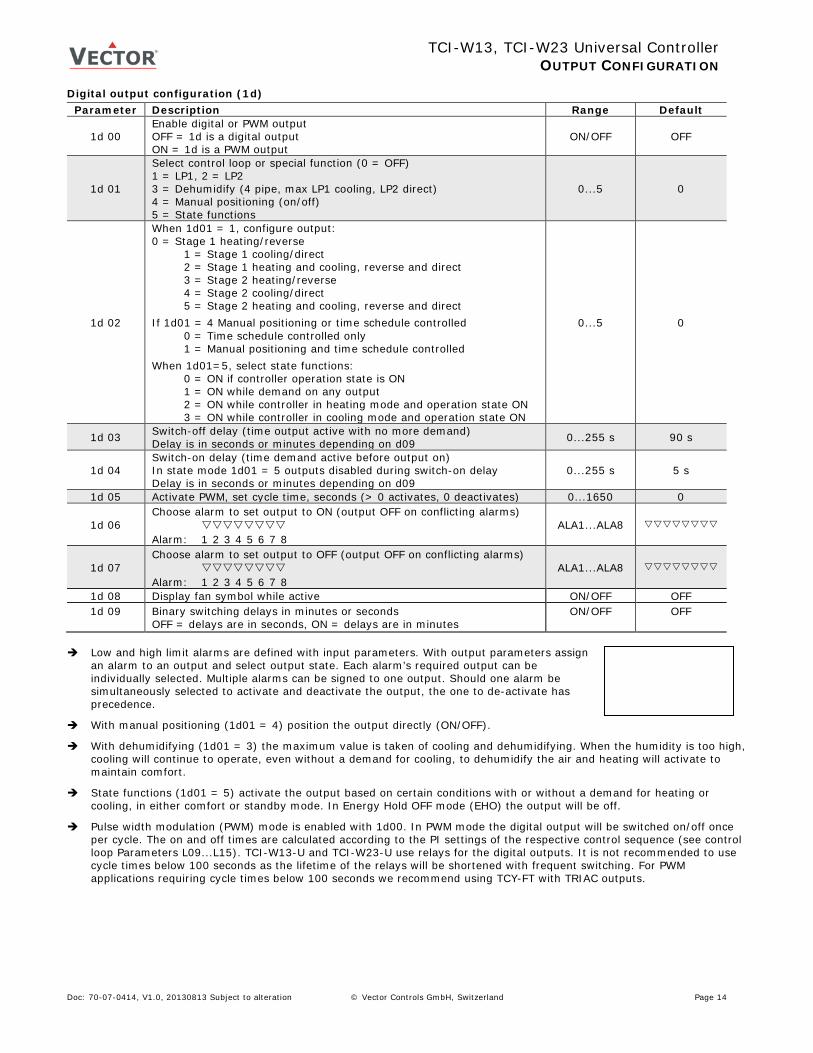
Low and high limit alarms are defined with input parameters. With output parameters assign
an alarm to an output and select output state. Each alarm’s required output can be individually selected. Multiple alarms can be signed to one output. Should one alarm be simultaneously selected to activate and deactivate the output, the one to de-activate has precedence.
With manual positioning (1d01 = 4) position the output directly (ON/OFF).
With dehumidifying (1d01 = 3) the maximum value is taken of cooling and dehumidifying. When the humidity is too high, cooling will continue to operate, even without a demand for cooling, to dehumidify the air and heating will activate to maintain comfort.
State functions (1d01 = 5) activate the output based on certain conditions with or without a demand for heating or cooling, in either comfort or standby mode. In Energy Hold OFF mode (EHO) the output will be off.
Pulse width modulation (PWM) mode is enabled with 1d00. In PWM mode the digital output will be switched on/off once per cycle. The on and off times are calculated according to the PI settings of the respective control sequence (see control loop Parameters L09...L15). TCI-W13-U and TCI-W23-U use relays for the digital outputs. It is not recommended to use cycle times below 100 seconds as the lifetime of the relays will be shortened with frequent switching. For PWM applications requiring cycle times below 100 seconds we recommend using TCY-FT with TRIAC outputs.
Doc: 70-07-0414, V1.0, 20130813 Subject to alteration © Vector Controls GmbH, Switzerland Page 14
TCI-W13, TCI-W23 Universal Controller
AUX FUNCTIONS CONFIGURATION Auxiliary functions Summer/winter compensation Parameter Description Range Default
Fu 00 Select compensation input (0 = function disabled): 1 = 1T, 2 = 1H, 3 = 1U, 4 = 2T 0...4 0
Fu 01 Winter compensation set point setback OFF = shift toward control loop heating set point minimum ON = shift toward control loop heating set point maximum
ON/OFF OFF
Fu 02 Winter compensation lower limit value – end shift per input 5 °C (41 °F) Fu 03 Winter compensation upper limit value – start shift per input 20 °C (68 °F)
Fu 04 Summer compensation set point setback OFF = shift toward control loop cooling set point minimum ON = shift toward control loop cooling set point maximum
ON/OFF ON
Fu 05 Summer compensation lower limit value – start shift per input 35 °C (95 °F)
Fu 06 Summer compensation upper limit value – end shift per input 40 °C (104 °F)
Fu 07 Show hot/cool symbol while compensation active ON/OFF OFF Comfort/economy mode changeover
Fu 08 Select comfort/economy changeover input (0= disabled): 1 = 1T, 2 = 1H, 3 = 1U, 4 = 2T
0...4 0
Fu 09 Economy activation delay (seconds) 0...1275 300 Fu 10 Input limit 1 per input 10 Fu 11 Input limit 2 Per input 90
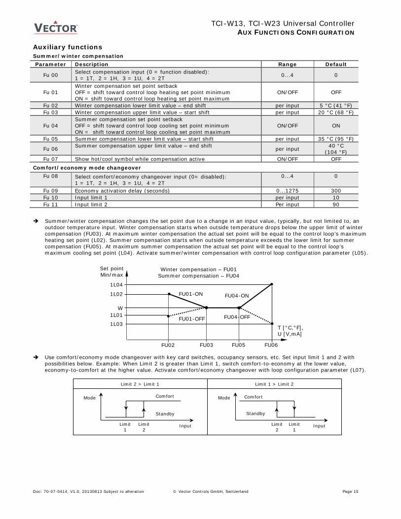
Summer/winter compensation changes the set point due to a change in an input value, typically, but not limited to, an
outdoor temperature input. Winter compensation starts when outside temperature drops below the upper limit of winter compensation (FU03). At maximum winter compensation the actual set point will be equal to the control loop’s maximum heating set point (L02). Summer compensation starts when outside temperature exceeds the lower limit for summer compensation (FU05). At maximum summer compensation the actual set point will be equal to the control loop’s maximum cooling set point (L04). Activate summer/winter compensation with control loop configuration parameter (L05).
Use comfort/economy mode changeover with key card switches, occupancy sensors, etc. Set input limit 1 and 2 with
possibilities below. Example: When Limit 2 is greater than Limit 1, switch comfort-to-economy at the lower value, economy-to-comfort at the higher value. Activate comfort/economy changeover with loop configuration parameter (L07).
1L03 FU04-OFF
Winter compensation – FU01 Summer compensation – FU04
1L02
T [°C,°F], U [V,mA]
FU02
FU01-ON
FU03
1L01 FU01-OFF
Set point Min/max
FU04-ON
1L04
FU05 FU06
W
Standby
Mode Mode Comfort
Input
Limit 2 > Limit 1
Comfort
Standby
Input
Limit 1 > Limit 2
Limit 1
Limit 2
Limit 2
Limit 1
Doc: 70-07-0414, V1.0, 20130813 Subject to alteration © Vector Controls GmbH, Switzerland Page 15
TCI-W13, TCI-W23 Universal Controller
AUX FUNCTIONS CONFIGURATION Enable/disable Parameter Description Range Default
Fu 12 Select enable–disable input (0= function disabled): 1 = 1T, 2 = 1H, 3 = 1U, 4 = 2T
0...4 0
FU 13 Manual override permitted (without waiting for delay). This function allows starting the controller, even the enable conditions are not met. The controller will switch off again if the running conditions are not met until the disable delay is expired.
ON/OFF OFF
Fu 14 Enable delay (seconds) 0...1275 0 Fu 15 Disable delay (seconds) 0...1275 300 Fu 16 Range of limits:
OFF = When limit 2 is greater than limit 1, enable when input value is greater than limit 2, disable when input value is less than limit 1. When limit 2 is less than limit 1, enable when input value less than limit 1, disable when input value is greater than limit 2
ON = When limit 2 is greater than limit 1 enable when input value is between limit 1 and limit 2. When limit 2 is less than limit 1, enable when input value below limit 2 or above limit 1
ON/OFF OFF
Fu 17 Input limit 1 per input 10 Fu 18 Input limit 2 Per input 90 Fu 19 Disable in case of alarms Selection
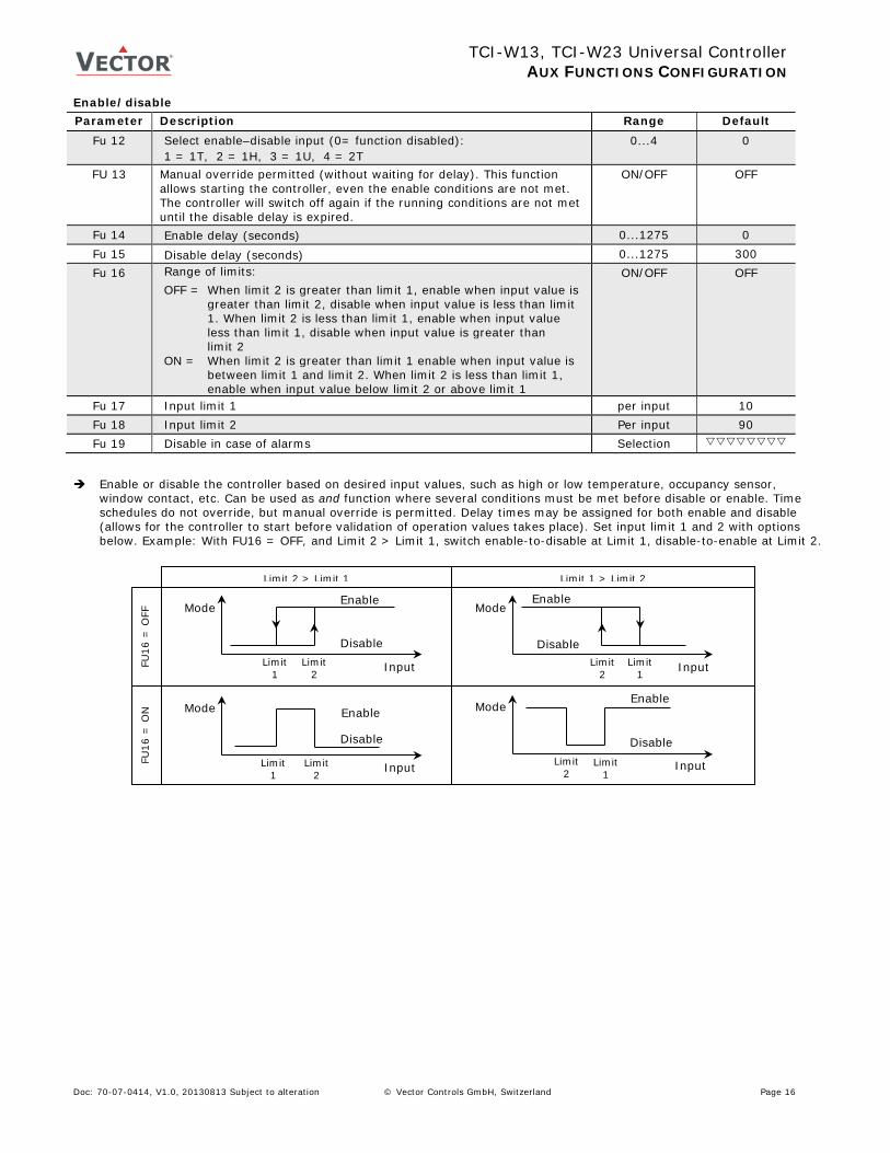
Enable or disable the controller based on desired input values, such as high or low temperature, occupancy sensor, window contact, etc. Can be used as and function where several conditions must be met before disable or enable. Time schedules do not override, but manual override is permitted. Delay times may be assigned for both enable and disable (allows for the controller to start before validation of operation values takes place). Set input limit 1 and 2 with options below. Example: With FU16 = OFF, and Limit 2 > Limit 1, switch enable-to-disable at Limit 1, disable-to-enable at Limit 2.
Limit 2 > Limit 1
Limit 1 > Limit 2 Enable
Disable
Input
Mode Enable
Disable
Input
Mode
FU16
= O
FF
FU16
= O
N
Enable
Disable
Input
Mode Enable
Disable
Input
Mode
Limit 1
Limit 2
Limit 2
Limit 1
Limit 1
Limit 2
Limit 2
Limit 1
Doc: 70-07-0414, V1.0, 20130813 Subject to alteration © Vector Controls GmbH, Switzerland Page 16
TCI-W13, TCI-W23 Universal Controller
AUX FUNCTIONS CONFIGURATION Heating/cooling mode changeover Parameter Description Range Default
Fu 20 Select heat/cool changeover input (0 = function disabled): 1 = 1T, 2 = 1H, 3 = 1U, 4 = 2T, 5 = h/c status loop 1, 6 = h/c status loop 2
0...6 0
Fu 21 Cooling activation delay (seconds) 0...1275 300 Fu 22 Input limit 1 per input 20 Fu 23 Input limit 2 per input 40
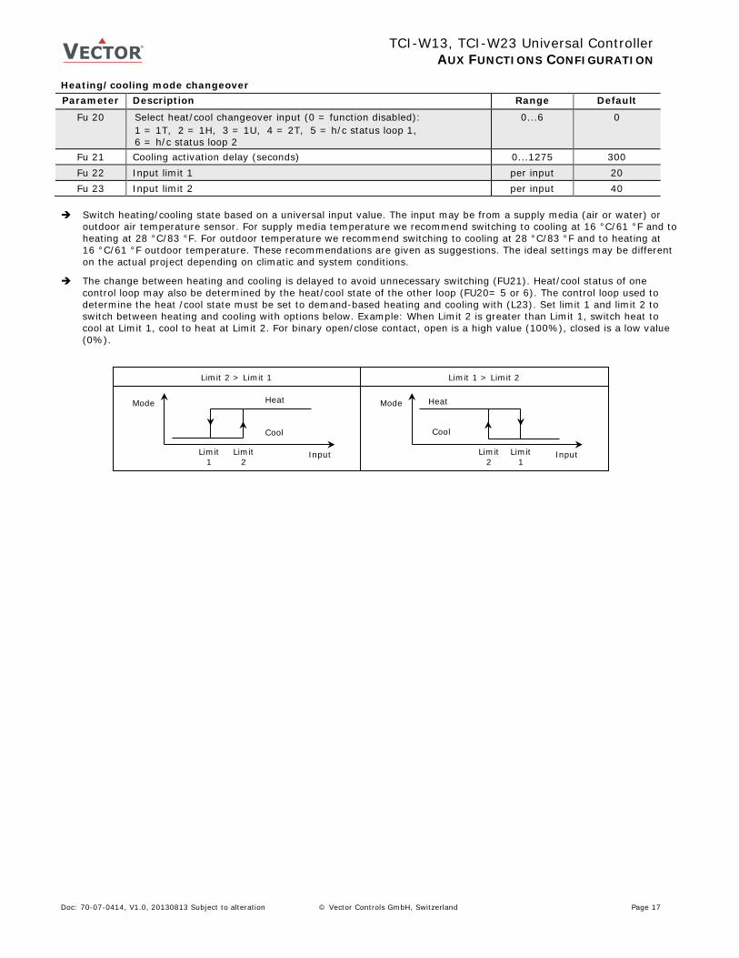
Switch heating/cooling state based on a universal input value. The input may be from a supply media (air or water) or
outdoor air temperature sensor. For supply media temperature we recommend switching to cooling at 16 °C/61 °F and to heating at 28 °C/83 °F. For outdoor temperature we recommend switching to cooling at 28 °C/83 °F and to heating at 16 °C/61 °F outdoor temperature. These recommendations are given as suggestions. The ideal settings may be different on the actual project depending on climatic and system conditions.
The change between heating and cooling is delayed to avoid unnecessary switching (FU21). Heat/cool status of one control loop may also be determined by the heat/cool state of the other loop (FU20= 5 or 6). The control loop used to determine the heat /cool state must be set to demand-based heating and cooling with (L23). Set limit 1 and limit 2 to switch between heating and cooling with options below. Example: When Limit 2 is greater than Limit 1, switch heat to cool at Limit 1, cool to heat at Limit 2. For binary open/close contact, open is a high value (100%), closed is a low value (0%).
Cool
Mode Mode Heat
Input
Limit 2 > Limit 1
Heat
Cool
Input
Limit 1 > Limit 2
Limit 1
Limit 2
Limit 2
Limit 1
Doc: 70-07-0414, V1.0, 20130813 Subject to alteration © Vector Controls GmbH, Switzerland Page 17