Embed Size (px)
Citation preview
Tailoring Systems Engineering Processes in a Conceptual Design Environment: a case study at
NASA Marshall Spaceflight Center’s ACO
John Mulqueen, C. Dauphne Maples, Leo Fabisinski, III Qualis Corporation (Engineering, Science and Technical Services [ESTS Group] contract),
NASA MSFC, International Space Systems, Inc. (ESTS Group) [email protected], [email protected], [email protected]
Copyright © 2012 by John Mulqueen, C. Dauphne Maples, and Leo Fabisinski, III. Published and used by INCOSE with permission.
Abstract. This paper provides an overview of Systems Engineering as it is applied in a conceptual design space systems department at the National Aeronautics and Space Administration (NASA) Marshall Spaceflight Center (MSFC) Advanced Concepts Office (ACO). Engineering work performed in the NASA MFSC’s ACO is targeted toward the Exploratory Research and Concepts Development life cycle stages, as defined in the International Council on Systems Engineering (INCOSE) System Engineering Handbook. This paper addresses three ACO Systems Engineering tools that correspond to three INCOSE Technical Processes: Stakeholder Requirements Definition, Requirements Analysis, and Integration, as well as one Project Process – Risk Management. These processes are used to facilitate, streamline, and manage systems engineering processes tailored for the earliest two life cycle stages, which is the environment in which ACO engineers work. The role of systems engineers and systems engineering as performed in ACO is explored in this paper. The need for tailoring Systems Engineering processes, tools, and products in the ever-changing engineering services ACO provides to its customers is addressed. Introduction. Systems engineering is a broad field with an even broader application that benefits a variety of engineering environments and workplaces. Various Systems Engineering disciplines, methods, and tools have been applied in ACO throughout the years. This paper examines the tailoring of Systems Engineering processes and tools currently being planned or used in ACO at NASA’s MSFC, as well as why former processes and tools evolved or were replaced. ACO has implemented various Systems Engineering practices and tools over the years as the dynamic nature of the office and the work performed has changed.
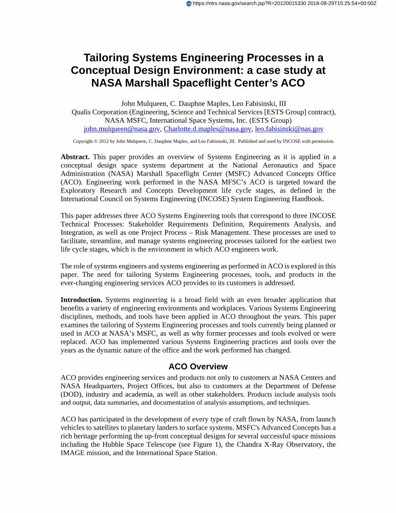
ACO Overview ACO provides engineering services and products not only to customers at NASA Centers and NASA Headquarters, Project Offices, but also to customers at the Department of Defense (DOD), industry and academia, as well as other stakeholders. Products include analysis tools and output, data summaries, and documentation of analysis assumptions, and techniques. ACO has participated in the development of every type of craft flown by NASA, from launch vehicles to satellites to planetary landers to surface systems. MSFC's Advanced Concepts has a rich heritage performing the up-front conceptual designs for several successful space missions including the Hubble Space Telescope (see Figure 1), the Chandra X-Ray Observatory, the IMAGE mission, and the International Space Station.
https://ntrs.nasa.gov/search.jsp?R=20120015330 2018-08-29T15:25:54+00:00Z
There are two teams within ACO: the Earth-to-Orbit (ETO) Team and the Space Systems Team. The ETO Team performs primarily launch vehicle analysis, and the Space Systems Team conducts studies on spacecraft, satellites, and other in-space vehicles and payloads.
Figure 1. Hubble Space Telescope
Engineering work performed in the NASA MFSC’s ACO is targeted toward the Exploratory Research and Concepts Development life cycle stages, as defined in the INCOSE System Engineering Handbook. ACO develops early reference architectures that are complete transportation architectures to meet customer needs. Starting with an analysis of customer requirements, ACO can analyze the reference missions and design a full complement of architecture elements (vehicles and surface systems) to best realize those requirements. This paper examines exploratory research and concept development in the ACO Space Systems Team. Once architecture has been chosen to realize mission requirements, the Space Systems Team in ACO develops one or more concepts for each required vehicle and surface element that is part of the Concept Development.
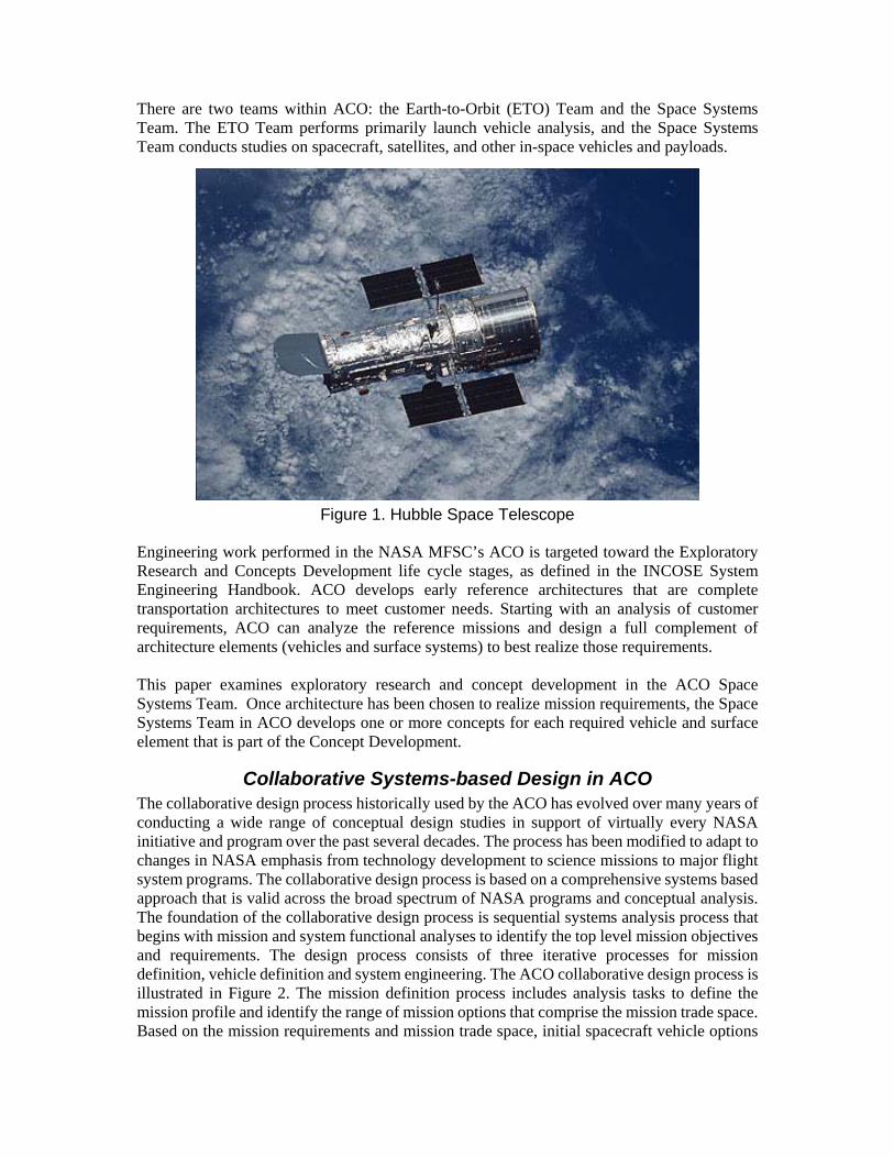
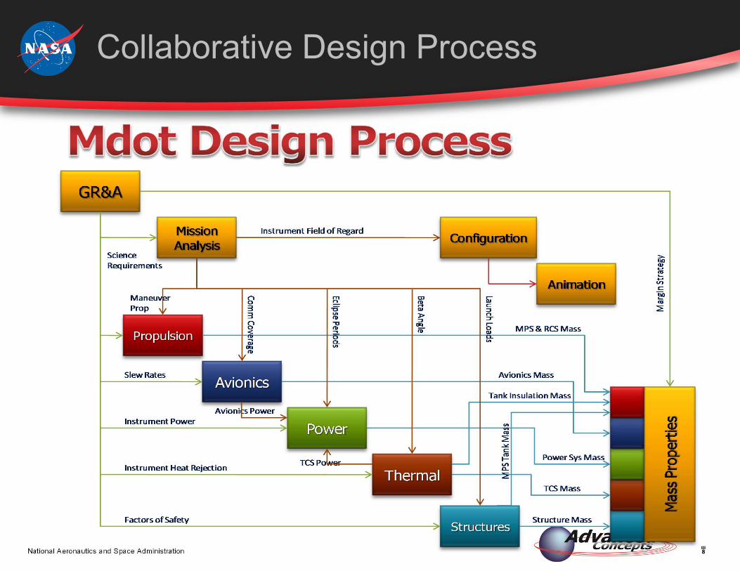
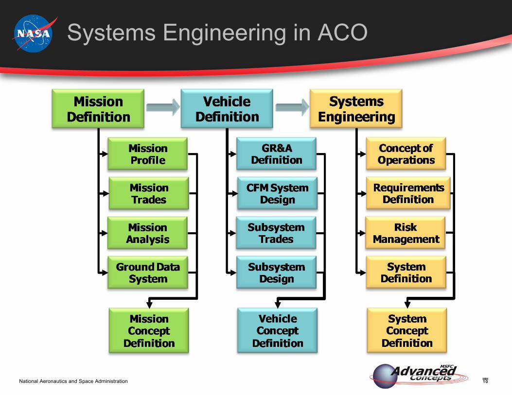
Collaborative Systems-based Design in ACO The collaborative design process historically used by the ACO has evolved over many years of conducting a wide range of conceptual design studies in support of virtually every NASA initiative and program over the past several decades. The process has been modified to adapt to changes in NASA emphasis from technology development to science missions to major flight system programs. The collaborative design process is based on a comprehensive systems based approach that is valid across the broad spectrum of NASA programs and conceptual analysis. The foundation of the collaborative design process is sequential systems analysis process that begins with mission and system functional analyses to identify the top level mission objectives and requirements. The design process consists of three iterative processes for mission definition, vehicle definition and system engineering. The ACO collaborative design process is illustrated in Figure 2. The mission definition process includes analysis tasks to define the mission profile and identify the range of mission options that comprise the mission trade space. Based on the mission requirements and mission trade space, initial spacecraft vehicle options
VehicleDefinition
Systems Engineering
Preliminary Mission Analysis
Mission Trade Space Definition
Vehicle Trade Space Definition
Preliminary GR&A Definition
Architecture Analysis
ArchitectureDefinition
MissionAnalysis
Initial Con‐Ops(Mission Profiles)
GR&ADefinition
Subsystem Trades
Vehicle Concept Definition
Requirements Definition
InterfaceDefinition
Risk Management
System Concept Definition
Con‐Ops Definition
and design ground rules and assumptions (GR&A) are defined. This process is often iterative, as mission requirements are derived from analysis of the mission and vehicle trade space. Results of the mission definition iterations contribute to the definition of the mission concept. The vehicle definition process is closely linked to the mission definition process. Vehicle definition is based on requirements derived from the mission analysis which become the basis for vehicle performance and subsystem design assumptions. Initial vehicle design GR&A not only shape the vehicle options and subsystem trades, but may eventually serve as the initial vehicle and subsystem requirements. The subsequent analysis of subsystem design trades and subsystem design analysis contribute to the definition of the vehicle concept. In parallel with the mission and vehicle definition processes, system engineering processes are conducted to the extent possible for conceptual design studies. These initial system engineering activities are compliant with the established NASA project formulation guidelines as specified in NASA Procedural Requirements document NPR 7120.1. The system engineering products developed at this early stage of program maturity often contribute to the specified system engineering products required for the Mission Concept Review (MCR) program key decision point. Initial system engineering activities consist of initial concept of operations and requirements definition. Initial system risk identification is often a valuable component of the system analysis. The system engineering analyses, integrated with the mission and vehicle concepts, contribute to the overall definition of the system concept.
Figure 2. Systems-based Collaborative Design Process
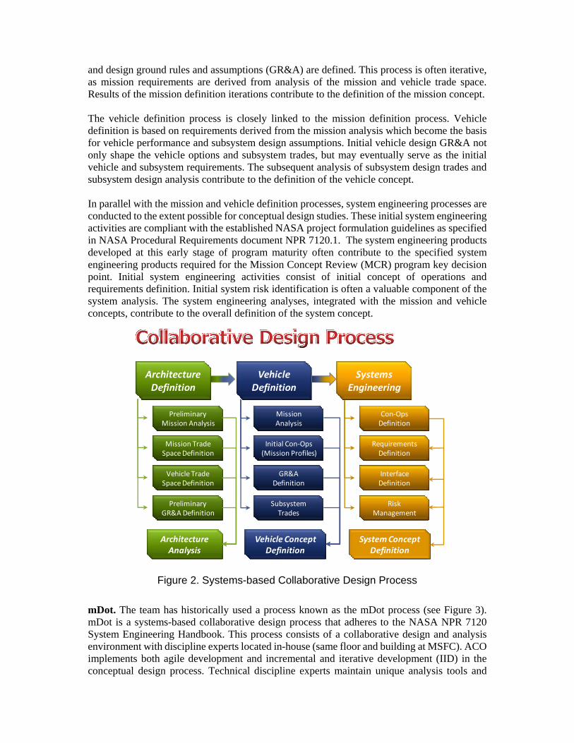
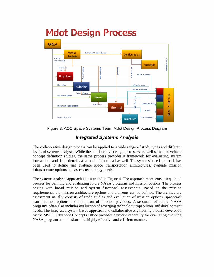
mDot. The team has historically used a process known as the mDot process (see Figure 3). mDot is a systems-based collaborative design process that adheres to the NASA NPR 7120 System Engineering Handbook. This process consists of a collaborative design and analysis environment with discipline experts located in-house (same floor and building at MSFC). ACO implements both agile development and incremental and iterative development (IID) in the conceptual design process. Technical discipline experts maintain unique analysis tools and
databases to enable rapid concept design capabilities. All mission and vehicle design disciplines work in a coordinated effort to converge to the desired analysis result or design solution. In most cases, the iterations are based on reaching a converged system mass estimate. For this reason, the design process is called the mDot Design Process. Figure 3 shows the basic steps and information flow of the mDot process. The key to the efficiency of this process is collaboration between disciplines, which is based on iterative analysis and transmission of analysis results to all related design disciplines, so dependencies and interactions between subsystems can be addressed. Figure 3 shows a simplified representation of the design process. Many interactions and feedback loops are not shown. Basically, the design process begins after initial study planning is completed. The study planning phase consists of gathering information from the study customer in the form of Needs, Goals, and Objectives (NGOs) and defining the mission concept. NGOs are used to develop an initial set of Ground Rules and Assumptions (GR&A). Depending on the study, a set of stakeholder/customer requirements is also developed. The initial mission and vehicle trade space is defined during the study planning process as well. Once the planning is complete, the design process is initiated with a review of the initial GR&A. Usually a joint design session is held in which each design discipline updates the initial GR&A for their particular subsystem. The design GR&A are documented and serve as the starting point for the design iteration. The GR&A are revisited each iteration because in many cases they must be adjusted as the study progresses. Mission analysis tasks are closely related to GR&A since the mission profile, trajectory, orbit analysis, and mission delta-velocity budget are all crucial to beginning many of the subsystem analyses. In many cases, an initial vehicle configuration is defined as a starting point for the subsystem design trades. Once there is sufficient information available to begin the vehicle subsystem analysis, the actual design iterations can begin. Within each design iteration data is passed between subsystem designers in a highly interactive fashion. Efficient communication, data management and documentation of design results are crucial to maintain the efficiency of the design process. In addition, each discipline maintains a keen awareness of the interactions and dependencies between subsystems. This allows overall system optimization of design results. ACO has recently purchased and begun to use a process management tool known as Vdot to integrate tasks and communication flows between disciplines during design iterations. Vdot is also used to manage resources, since engineers are often supporting more than one study or ACO activity at a time. This tool is discussed in more detail in later sections of this paper.
GR&A
Mission Analysis
Power
Avionics
Propulsion
Thermal
StructuresFactors of Safety Structure Mass
MPS Tank Mass
TCS Power
Avionics Power
Tank Insulation Mass
TCS Mass
Power Sys Mass
Avionics Mass
MPS & RCS Mass
Mas
s Pr
oper
ties
ManeuverProp
Eclipse P
eriods
CommCoverage
ScienceRequirements
Instrument Power
Slew Rates
Instrument Heat Rejection
Margin Strategy
Configuration
Beta A
ngle
Launch Lo
ads
Instrument Field of Regard
Animation
Figure 3. ACO Space Systems Team Mdot Design Process Diagram
Integrated Systems Analysis
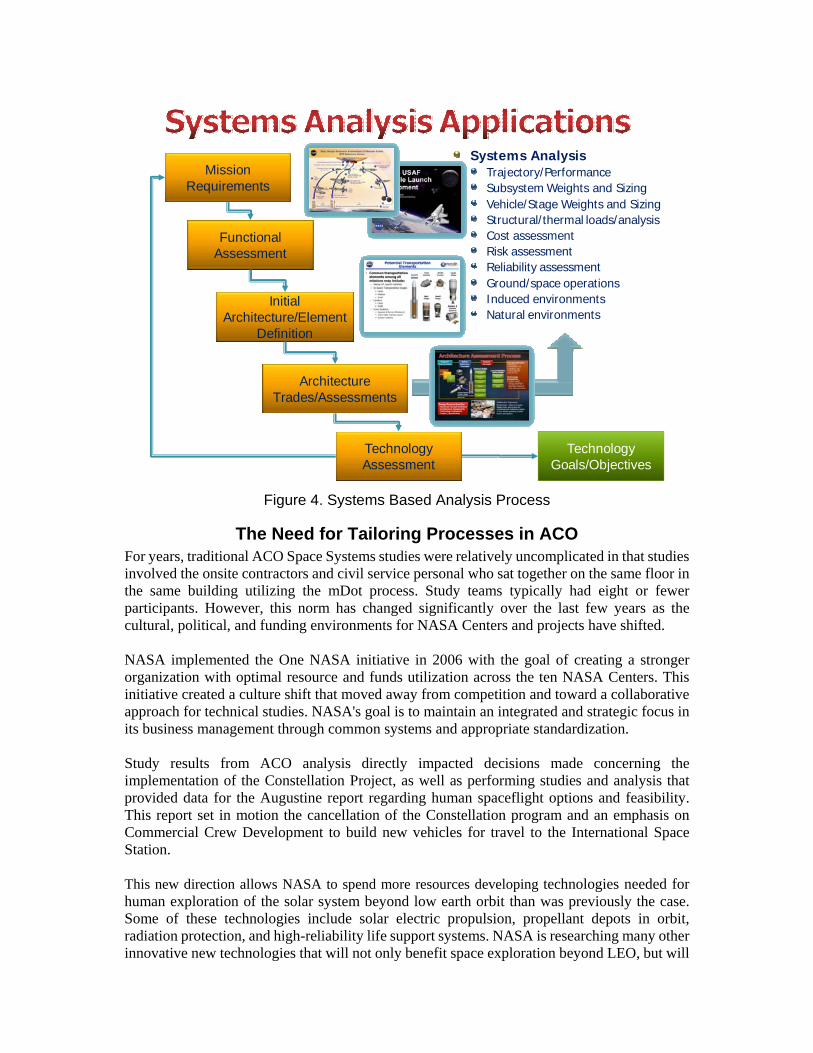
The collaborative design process can be applied to a wide range of study types and different levels of systems analysis. While the collaborative design processes are well suited for vehicle concept definition studies, the same process provides a framework for evaluating system interactions and dependencies at a much higher level as well. The systems based approach has been used to define and evaluate space transportation architectures, evaluate mission infrastructure options and assess technology needs. The systems analysis approach is illustrated in Figure 4. The approach represents a sequential process for defining and evaluating future NASA programs and mission options. The process begins with broad mission and system functional assessments. Based on the mission requirements, the mission architecture options and elements can be defined. The architecture assessment usually consists of trade studies and evaluation of mission options, spacecraft transportation options and definition of mission payloads. Assessment of future NASA programs often also includes evaluation of emerging technology capabilities and development needs. The integrated system based approach and collaborative engineering process developed by the MSFC Advanced Concepts Office provides a unique capability for evaluating evolving NASA program and missions in a highly effective and efficient manner.
Systems AnalysisTrajectory/PerformanceSubsystem Weights and SizingVehicle/Stage Weights and SizingStructural/thermal loads/analysisCost assessmentRisk assessmentReliability assessmentGround/space operationsInduced environmentsNatural environments
Mission Requirements
Functional Assessment
Architecture Trades/Assessments
Initial Architecture/Element
Definition
Technology Assessment
Technology Goals/Objectives
Figure 4. Systems Based Analysis Process
The Need for Tailoring Processes in ACO For years, traditional ACO Space Systems studies were relatively uncomplicated in that studies involved the onsite contractors and civil service personal who sat together on the same floor in the same building utilizing the mDot process. Study teams typically had eight or fewer participants. However, this norm has changed significantly over the last few years as the cultural, political, and funding environments for NASA Centers and projects have shifted. NASA implemented the One NASA initiative in 2006 with the goal of creating a stronger organization with optimal resource and funds utilization across the ten NASA Centers. This initiative created a culture shift that moved away from competition and toward a collaborative approach for technical studies. NASA's goal is to maintain an integrated and strategic focus in its business management through common systems and appropriate standardization. Study results from ACO analysis directly impacted decisions made concerning the implementation of the Constellation Project, as well as performing studies and analysis that provided data for the Augustine report regarding human spaceflight options and feasibility. This report set in motion the cancellation of the Constellation program and an emphasis on Commercial Crew Development to build new vehicles for travel to the International Space Station. This new direction allows NASA to spend more resources developing technologies needed for human exploration of the solar system beyond low earth orbit than was previously the case. Some of these technologies include solar electric propulsion, propellant depots in orbit, radiation protection, and high-reliability life support systems. NASA is researching many other innovative new technologies that will not only benefit space exploration beyond LEO, but will
improve life on earth in unexpected, unanticipated ways once these technologies move beyond the exploratory research and concept development stages and are developed and matured. Many such technology spin-offs have occurred already, such as memory foam and inflatable satellite communication systems. NASA was previously more focused on later life cycle stages, such as development and production – and in the case of the Space Shuttle and many lesser known projects and programs within NASA – utilization, support, and retirement. As a result of the One NASA initiative and the direction toward new technology development, MSFC’s ACO has been working with engineers, groups, and organizations outside ACO, both at MSFC and other NASA Centers. This has become increasingly frequent for new studies over the past two years. The need for systems engineering processes, standards, tools, and integration efforts has never been greater in the MSFC ACO. Whereas study teams in ACO once were one engineer deep per discipline, they have often grown to include teams within teams; for example, an avionics team might consist of eight engineers from MSFC and other avionics engineers from JSC, KSC, GRC, or GSFC. For one recent study, the team included over 70 participants across five NASA Centers, in addition to the core ACO design team. The vast majority of new study team members have had little or no experience with the exploratory research or concept development life cycle stages. Many study participants not part of the MSFC ACO core Space Systems design team have most of their engineering experience in later life cycle stages. This fact increases the complexity naturally involved in working with larger groups of people. For concept studies that involve other MSFC team members or engineers from other NASA Centers, new and innovative systems engineering and systems integration processes and procedures have become necessary. The ACO Space Systems Team has purchased a commercial-off-the-shelf process management tool to assist with the systems integration activities on studies that include study team members other than the core ACO Design Team. ACO has also developed an in-house Risk Management tool to facilitate incorporating risk into all ACO Space Systems studies. An in-house Requirements Analysis and Requirements Management tool is also being developed for use in the concept development studies. In addition, the Space Systems Team Lead has implemented numerous changes in policies, processes, and product standardization that will address many of these new challenges.
Tailoring Systems Integration in ACO New and innovative approaches to systems integration, including tools, processes, and personnel, are a must to deal with the new level of complexity that has been introduced into the ACO Space Systems studies. Tailoring systems engineering activities in ACO has been, and continues to be, an ongoing process. New planning and control processes, procedures, tools, and policies are being adopted even as this paper is being written in order to deal with these needs. Standard Systems Integration is not done in ACO because of the early life cycle phases implemented – Exploratory Research and Concept Development. Thus, tailoring systems integration is done to meet the unique needs of the ACO engineering environment. The majority of all engineering disciplines focus almost exclusively on the details of individual aspects of a particular system or “discipline,” such as avionics, power, thermal, etc. Systems
engineering focuses on the integration of the various engineering disciplines into a comprehensive, effective system. The systems integrator in ACO helps to facilitate communication among the subsystem experts and also ensures that discipline inputs and outputs are provided in the order needed to complete a design iteration in a timely manner to meet the study schedule. Systems integration activities within ACO have traditionally been done in-person between discipline engineers and/or with an ACO systems engineer integrating design team communication between subsystems. This is done in formal team meetings, working meetings, and via office visits. ACO has recently begun using a tool called Vdot, which is discussed in the next section, to improve systems integration processes in the office. These processes correspond to the INCOSE Technical Process of Integration. For concept studies that involve other MSFC team members or engineers from other NASA Centers, new study and systems integration processes and procedures have become necessary. The ACO Space Systems Team has purchased a commercial-off-the-shelf process management tool to assist with the systems integration activities necessary on the majority of ACO studies, which now involved more that core ACO Design Team members. ACO discipline experts in the Space Systems Team will take on some of the systems integration responsibilities when there are subsystem teams on a study rather that a single ACO discipline expert. ACO discipline experts have limited systems integration responsibilities to ensure that they have time to do subsystem analysis and necessary design trades. However, each ACO subsystem engineer (discipline expert) will interact with the ACO systems engineer and provide all subsystem inputs and data for that studies subsystem team.
Vdot™ To succeed in improving the efficiency of any team, capturing the processes employed to a sufficient level of detail to understand the flow of information, tasks, and deliverables that are required to produce products, or in the case of ACO, study inputs. This information needs to be accessible to both study leads, systems engineering integrators, and core ACO Space Systems Design Team members to ensure that subsystem engineering teams and team members physically located outside of ACO are all using the same GR&A and study requirements. This has not always been the case when using the mDot collaborative design systems-based process on large, multi-organization and/or multi-center study teams. Engineers located in other organizations with MSFC or at other NASA Centers have sometimes used data and requirements that were not consistent with the overall study. This has caused deadline delays and rework in some cases. To address these concerns, ACO is implementing the use of a commercial-off-the-shelf process management and systems integration tool called Vdot™. The software tool, whose name is derived from the mathematical symbol for the derivative of velocity (acceleration), is available from the ESI Group. The tool provides the ability to define, deploy, and execute desktop processes for teams in a distributed network environment. Vdot provides the ability to route data, launch tools (IT applications), and provide automatic real-time project status. The tool uses a point and click graphical interface, as shown in Figure 5, to facilitate quick process definition. A feature in Vdot known as “Smart Tasks” provides everything needed for the task at hand, already gathered into a package and delivered to the point of action.

Figure 5. Defining Value Streams using Vdot’s Process Editor. Behind the scenes, an “as-performed” database captures a complete history of the events that occur during process execution. This includes information about when tasks begin, when tasks are finished, and who is assigned to complete tasks. Vdot’s dashboards and task lists are tied directly to the state of an ACO study’s processes, as well as to the engineers working them. This means that Vdot provides real-time progress visibility, which is shown in Figure 6.
Figure 6. Vdot Enables Real-Time Progress Visibility.
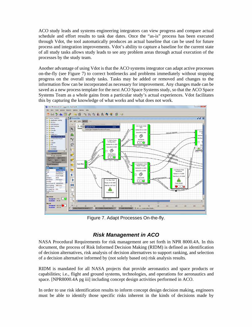
ACO study leads and systems engineering integrators can view progress and compare actual schedule and effort results to task due dates. Once the “as-is” process has been executed through Vdot, the tool automatically produces an actual baseline that can be used for future process and integration improvements. Vdot’s ability to capture a baseline for the current state of all study tasks allows study leads to see any problem areas through actual execution of the processes by the study team. Another advantage of using Vdot is that the ACO systems integrator can adapt active processes on-the-fly (see Figure 7) to correct bottlenecks and problems immediately without stopping progress on the overall study tasks. Tasks may be added or removed and changes to the information flow can be incorporated as necessary for improvement. Any changes made can be saved as a new process template for the next ACO Space Systems study, so that the ACO Space Systems Team as a whole gains from a particular study’s actual experiences. Vdot facilitates this by capturing the knowledge of what works and what does not work.
Figure 7. Adapt Processes On-the-fly.
Risk Management in ACO NASA Procedural Requirements for risk management are set forth in NPR 8000.4A. In this document, the process of Risk Informed Decision Making (RIDM) is defined as identification of decision alternatives, risk analysis of decision alternatives to support ranking, and selection of a decision alternative informed by (not solely based on) risk analysis results. RIDM is mandated for all NASA projects that provide aeronautics and space products or capabilities; i.e., flight and ground systems, technologies, and operations for aeronautics and space. [NPR8000.4A pg iii] including concept design activities performed in ACO. In order to use risk identification results to inform concept design decision making, engineers must be able to identify those specific risks inherent in the kinds of decisions made by
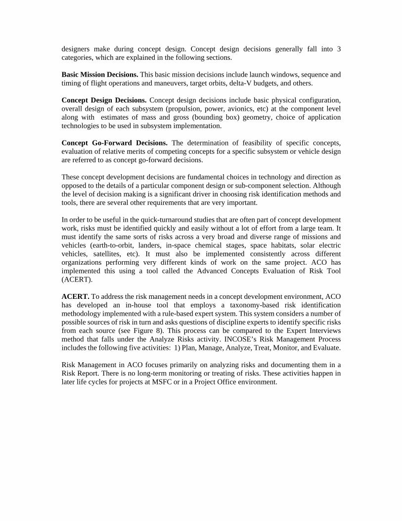
designers make during concept design. Concept design decisions generally fall into 3 categories, which are explained in the following sections. Basic Mission Decisions. This basic mission decisions include launch windows, sequence and timing of flight operations and maneuvers, target orbits, delta-V budgets, and others. Concept Design Decisions. Concept design decisions include basic physical configuration, overall design of each subsystem (propulsion, power, avionics, etc) at the component level along with estimates of mass and gross (bounding box) geometry, choice of application technologies to be used in subsystem implementation. Concept Go-Forward Decisions. The determination of feasibility of specific concepts, evaluation of relative merits of competing concepts for a specific subsystem or vehicle design are referred to as concept go-forward decisions. These concept development decisions are fundamental choices in technology and direction as opposed to the details of a particular component design or sub-component selection. Although the level of decision making is a significant driver in choosing risk identification methods and tools, there are several other requirements that are very important. In order to be useful in the quick-turnaround studies that are often part of concept development work, risks must be identified quickly and easily without a lot of effort from a large team. It must identify the same sorts of risks across a very broad and diverse range of missions and vehicles (earth-to-orbit, landers, in-space chemical stages, space habitats, solar electric vehicles, satellites, etc). It must also be implemented consistently across different organizations performing very different kinds of work on the same project. ACO has implemented this using a tool called the Advanced Concepts Evaluation of Risk Tool (ACERT). ACERT. To address the risk management needs in a concept development environment, ACO has developed an in-house tool that employs a taxonomy-based risk identification methodology implemented with a rule-based expert system. This system considers a number of possible sources of risk in turn and asks questions of discipline experts to identify specific risks from each source (see Figure 8). This process can be compared to the Expert Interviews method that falls under the Analyze Risks activity. INCOSE’s Risk Management Process includes the following five activities: 1) Plan, Manage, Analyze, Treat, Monitor, and Evaluate. Risk Management in ACO focuses primarily on analyzing risks and documenting them in a Risk Report. There is no long-term monitoring or treating of risks. These activities happen in later life cycles for projects at MSFC or in a Project Office environment.
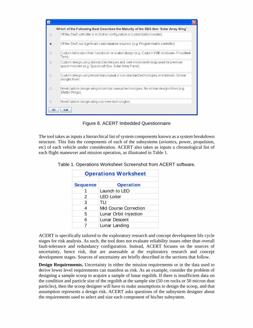
Sequence Operation1 Launch to LEO2 LEO Loiter3 TLI4 Mid Course Correction5 Lunar Orbit Injection6 Lunar Descent7 Lunar Landing
Operations Worksheet
Figure 8. ACERT Imbedded Questionnaire
The tool takes as inputs a hierarchical list of system components known as a system breakdown structure. This lists the components of each of the subsystems (avionics, power, propulsion, etc) of each vehicle under consideration. ACERT also takes as inputs a chronological list of each flight maneuver and mission operation, as illustrated in Table 1.
Table 1. Operations Worksheet Screenshot from ACERT software. ACERT is specifically tailored to the exploratory research and concept development life cycle stages for risk analysis. As such, the tool does not evaluate reliability issues other than overall fault-tolerance and redundancy configuration. Instead, ACERT focuses on the sources of uncertainty, hence risk, that are assessable at the exploratory research and concept development stages. Sources of uncertainty are briefly described in the sections that follow.
Design Requirements. Uncertainty in either the mission requirements or in the data used to derive lower level requirements can manifest as risk. As an example, consider the problem of designing a sample scoop to acquire a sample of lunar regolith. If there is insufficient data on the condition and particle size of the regolith at the sample site (50 cm rocks or 50 micron dust particles), then the scoop designer will have to make assumptions to design the scoop, and that assumption represents a design risk. ACERT asks questions of the subsystem designer about the requirements used to select and size each component of his/her subsystem.
Component Maturity. In designing a subsystem at the concept development stage, representative components are chosen and sized with the assumption that similar components will be included in the final design. ACERT asks the subsystem designer questions about the maturity of each component. Components with little flight heritage pose risks. Components that rely on undeveloped technologies pose even greater risks. ACERT uses information on the maturity of each component to assess the risk of including it.
Component Availability. Components and materials supplied off-the-shelf pose less risk than those that must be built to order. There is additional risk incurred if a component or material is available from only one supplier or requires long lead time to deliver. ACERT asks the subsystem designer about the availability and vendor status of each component.
Test Planning and Facilities. Uncertainties in the planning of unit and integration tests and in the facilities available for those tests manifest risk. ACERT asks subsystem designers questions about the planned testing of each subsystem component. Is there an existing test plan? Can the component be fully tested before flight? Do facilities sufficient for the test exist?
Component Development. If a design component does not exist and will require development, risk must be assessed based on the uncertainties with the development plan and process. ACERT asks the designer questions about the plan for developing the component. Is there a complete development plan in place? Do required technologies exist?
Inherent Operational Risk. Each flight maneuver and mission operation has inherent risks. Situational and environmental factors may incur further risks while these are being performed. Automated rendezvous and docking in low Earth orbit incurs risk, but it has been done successfully. It has not been successfully accomplished in lunar orbit where there are many more uncertainties. ACERT takes a mission operations sequence as input and asks questions to assess risk based on how much uncertainty there appears to be in the mission operations plan.
Integration. Although engineers performing concept development design cannot accurately predict the precise reliability of each subsystem, engineers can make some overall assessments based on the redundancy of components integrated into the subsystem. ACERT asks questions about fault-tolerance and redundancy to assess reliability in a gross way.
Requirements ACO has traditionally met with customers and used an expectations questionnaire to define spacecraft requirements for studies in the study planning phase. GR&A, which are derived from top-level customer requirements, have been documented via Excel spreadsheets, as well. Customer Needs, Goals, and Objectives (NGO) typically overlap with some ground rules for a study. After defining NGOs, they are allocated to the correct requirement category and level, i.e., programmatic, mission, functional/performance. Well-defined payload (i.e., science instrument) data and spacecraft requirements result in a more rapid turnaround with more confidence in the analysis results. Stakeholder requirements analysis is done prior to engaging the design team. Thus, there is overlap in ACO between the two INCOSE Technical Processes of Stakeholder Requirements Definition and Requirements Analysis. The use of Dynamic Object-Oriented Requirements System (DOORS) or other database tools is not required in ACO due to the relatively small number of requirements needed for each study. This is the case for both Stakeholder Requirements definition and Requirements Analysis. ACO typically uses Excel and Power Point to develop requirements trees (see Figure 9) and top-level requirements. Traceability and the tracking of requirement attributes are maintained using Excel. Compliance, validation, or verification data is also included as a
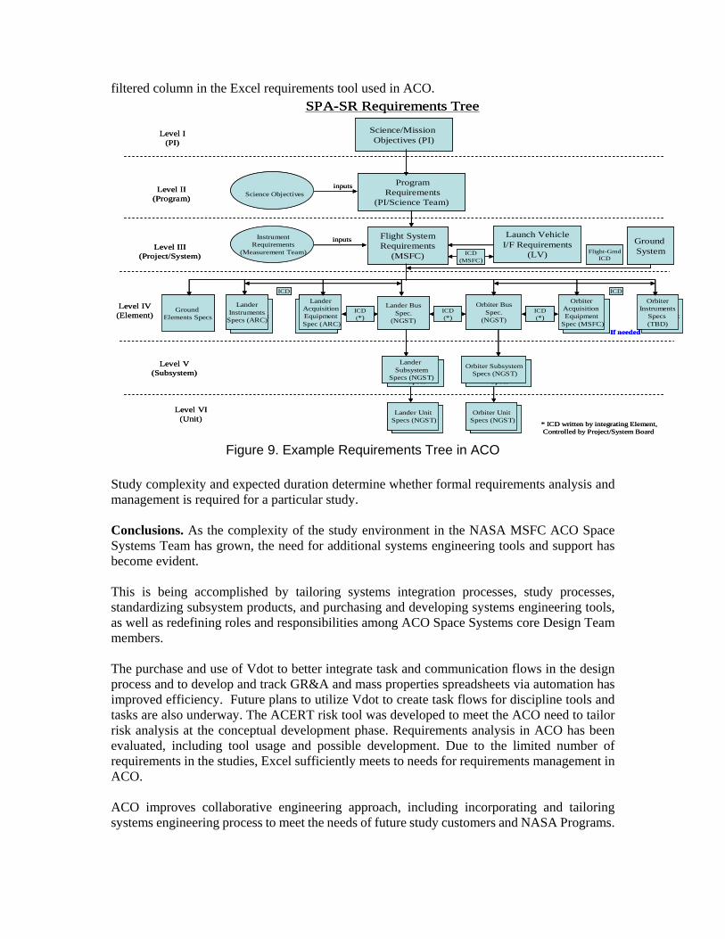
filtered column in the Excel requirements tool used in ACO.
Rover/HopperSubsystem
Specs
LanderSubsystem
Specs
SMSInstrument
Specs
SPA-SR Requirements Tree
ProgramRequirements
(PI/Science Team)
Science/Mission Objectives (PI)
Flight SystemRequirements
(MSFC)
Launch VehicleI/F Requirements
(LV)
Orbiter BusSpec.
(NGST)
InstrumentRequirements
(Measurement Team)
Lander BusSpec.
(NGST)
Ground Elements Specs
LanderSubsystem
Specs (NGST)
Orbiter SubsystemSpecs (NGST)
Level I (PI)
Level II(Program)
Level III(Project/System)
Level IV(Element)
Level V(Subsystem)
Level VI(Unit) Component
Specs
Orbiter UnitSpecs (NGST)
inputs
inputs
ICD(MSFC)
OrbiterAcquisition Equipment
Spec (MSFC)
LanderInstrument
Specs
LanderAcquisition EquipmentSpec (ARC)
Science Objectives
ComponentSpecs
Lander UnitSpecs (NGST)
ICD(*)
ICD(*)
ICD(*)
* ICD written by integrating Element,Controlled by Project/System Board
Ground SystemFlight-Grnd
ICD
SMSInstrument
Specs
LanderInstruments
Specs (ARC)
SMSInstrument
Specs
OrbiterInstruments
Specs (TBD)
If needed
ICD ICD
Rover/HopperSubsystem
Specs
LanderSubsystem
Specs
SMSInstrument
Specs
SPA-SR Requirements Tree
ProgramRequirements
(PI/Science Team)
Science/Mission Objectives (PI)
Flight SystemRequirements
(MSFC)
Launch VehicleI/F Requirements
(LV)
Orbiter BusSpec.
(NGST)
InstrumentRequirements
(Measurement Team)
Lander BusSpec.
(NGST)
Ground Elements Specs
LanderSubsystem
Specs (NGST)
Orbiter SubsystemSpecs (NGST)
Level I (PI)
Level II(Program)
Level III(Project/System)
Level IV(Element)
Level V(Subsystem)
Level VI(Unit) Component
Specs
Orbiter UnitSpecs (NGST)
ComponentSpecs
Orbiter UnitSpecs (NGST)
inputs
inputs
ICD(MSFC)
OrbiterAcquisition Equipment
Spec (MSFC)
LanderInstrument
Specs
LanderAcquisition EquipmentSpec (ARC)
LanderInstrument
Specs
LanderAcquisition EquipmentSpec (ARC)
Science Objectives
ComponentSpecs
Lander UnitSpecs (NGST)
ComponentSpecs
Lander UnitSpecs (NGST)
ICD(*)
ICD(*)
ICD(*)
* ICD written by integrating Element,Controlled by Project/System Board
Ground SystemFlight-Grnd
ICD
SMSInstrument
Specs
LanderInstruments
Specs (ARC)
SMSInstrument
Specs
OrbiterInstruments
Specs (TBD)
If needed
ICD ICD
Figure 9. Example Requirements Tree in ACO
Study complexity and expected duration determine whether formal requirements analysis and management is required for a particular study. Conclusions. As the complexity of the study environment in the NASA MSFC ACO Space Systems Team has grown, the need for additional systems engineering tools and support has become evident. This is being accomplished by tailoring systems integration processes, study processes, standardizing subsystem products, and purchasing and developing systems engineering tools, as well as redefining roles and responsibilities among ACO Space Systems core Design Team members. The purchase and use of Vdot to better integrate task and communication flows in the design process and to develop and track GR&A and mass properties spreadsheets via automation has improved efficiency. Future plans to utilize Vdot to create task flows for discipline tools and tasks are also underway. The ACERT risk tool was developed to meet the ACO need to tailor risk analysis at the conceptual development phase. Requirements analysis in ACO has been evaluated, including tool usage and possible development. Due to the limited number of requirements in the studies, Excel sufficiently meets to needs for requirements management in ACO. ACO improves collaborative engineering approach, including incorporating and tailoring systems engineering process to meet the needs of future study customers and NASA Programs.
References
Fabisinski, L. and Maples, C.D. 2010. “Risk Evaluation in the Pre-Phase A Conceptual design of Spacecraft.” Conference Paper. Anaheim, CA (US): AIAA Space 2010 Conference and Exposition.
Everett, C. 2008. “NPR 8000.4A, NASA Procedural Requirements: Agency Risk Management Procedural Requirements.” NASA Procedural Requirement Document. Huntsville, AL (US).
Haskins, C., ed. 2011. Systems Engineering Handbook: A Guide for System Life Cycle Processes and Activities. Version 3.2. Revised by M. Krueger, David Walden, and R. Douglas Hamelin. San Diego, CA (US): INCOSE.
Herdy, R. and Yanez, D. 2009. “Vdot™ A COTS Tool To Optimize Aerospace Processes. White Paper. Orlando, FL (US): AIAA Aerospace Sciences Conference 2009.
Mulqueen, J., Jones, D. and Hopkins, R. 2011. “The MSFC Collaborative Engineering Process for Preliminary Design and Concept Definition Studies.” Conference Paper. Long Beach, CA (US): AIAA Space 2011 Conference and Exposition.
Biographies John Mulqueen works for NASA as the MSFC ACO Space Systems Team Lead. He has supported NASA human Mars and lunar mission transportation studies for over twenty years. He served as Next Generation Launch Technology Lead for Guidance Navigation and Control Technologies and as Lead Systems Engineer for Flight Mechanics Project during the 2nd Generation Reusable Launch Vehicle Program. His technical background is in launch vehicle guidance navigation and control software development and orbital mechanics. He holds a Master of Science from the University of Alabama in Huntsville (UAH), 1991 and a Bachelor of Science from West Virginia University, 1980. C. Dauphne Maples is a Systems Engineer at Qualis and has supported MSFC since 2004. Ms. Maples is ESTS Task Lead in ACO. Her technical background includes Mass Properties, Mission Analysis, Requirements Management, and Risk Analysis. Ms. Maples obtained a Bachelor’s Degree from the University of Huntsville in Alabama in 2001. She completed the UAH Systems Engineering Certificate (2006) and completed coursework toward a Bachelor’s Degree in Computer Science from Athens State University (2009). She expects certification through INCOSE’s CSEP exam in 2012 and is a member of AIAA, INCOSE, and the Society of Women Engineers (SWE) Secretary, Outreach Chair. Mr. Fabisinski graduated from Vanderbilt University with a Bachelor’s Degree in both History and Electrical Engineering. His work experience has included software engineering, digital audio engineering, project management, and risk analysis. He is employed as a senior engineer at International Space Systems, Inc. (ISSI) on the Jacobs ESTS Group contract. Currently Mr. Fabisinski works in the ACO at NASA’s Marshall Spaceflight Center. His principal responsibilities are Modeling and Simulation, Risk Analysis, and Power Systems Design. He is a senior member of AIAA.
National Aeronautics and Space Administration
www.nasa.gov
Tailoring Systems Engineering Processes in a Conceptual Design Environment:A case study at NASA Marshall Spaceflight Center’sAdvanced Concepts Office
Authors: John Mulqueen (NASA)C. Dauphne Maples (Qualis)Leo Fabisinski, III (ISSI)
2National Aeronautics and Space Administration
Agenda
MSFC Organizational ChartAdvanced Concepts Office (ACO)ACO Space Systems TeamPre-Phase A Concept DevelopmentCollaborative Design ProcessSystems AnalysisSystems Engineering in ACOProcess ImprovementsSystems IntegrationRequirementsRiskAdvanced Concepts Evaluation of Risk Tool (ACERT)Conclusions
3National Aeronautics and Space Administration
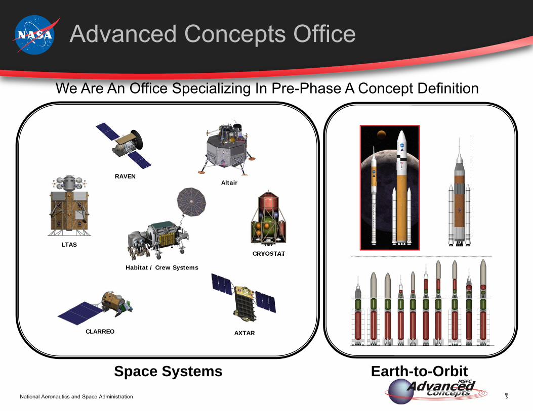
We Are An Office Specializing In Pre-Phase A Concept Definition
Advanced Concepts Office
Space Systems Earth-to-Orbit
CRYOSTAT
Habitat / Crew Systems
LTAS
AXTAR
AltairRAVEN
CLARREO
4National Aeronautics and Space Administration
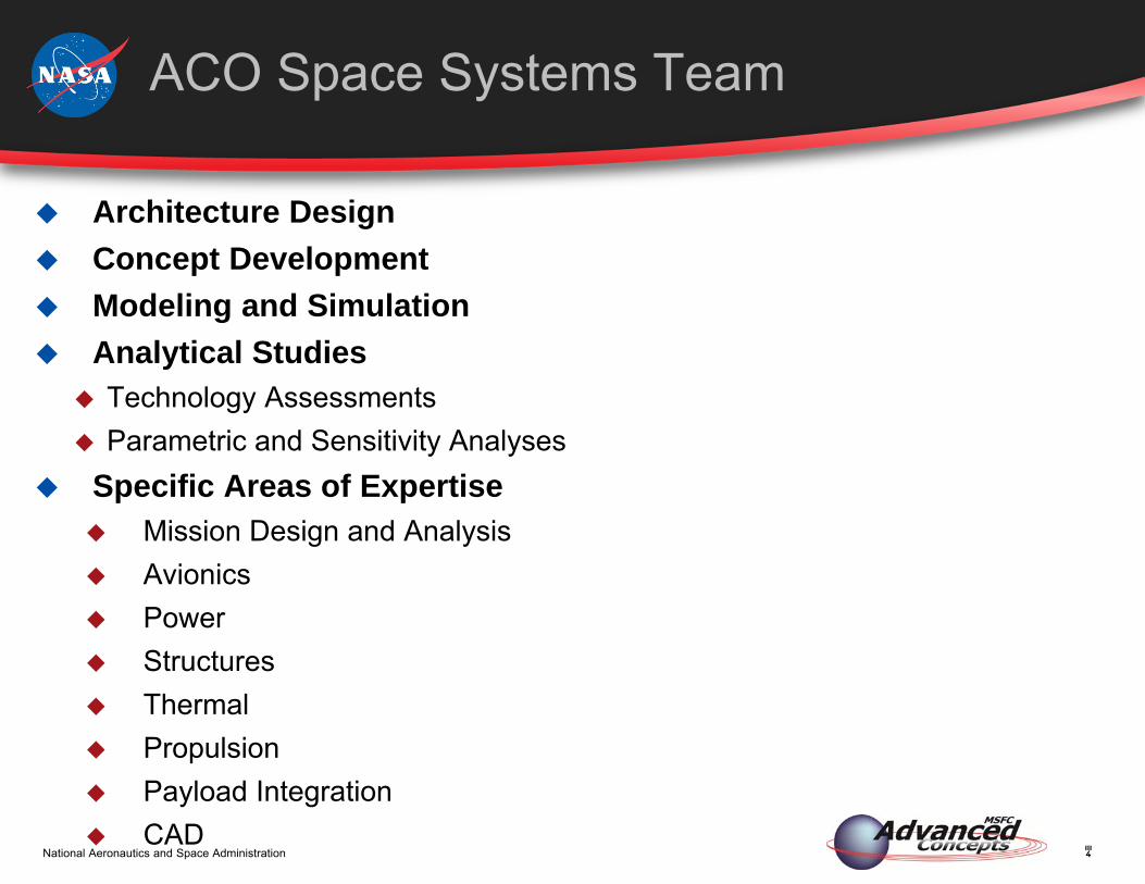
ACO Space Systems Team
Architecture Design Concept Development Modeling and Simulation Analytical Studies
Technology Assessments Parametric and Sensitivity Analyses
Specific Areas of Expertise Mission Design and Analysis Avionics Power Structures Thermal Propulsion Payload Integration CAD
5National Aeronautics and Space Administration
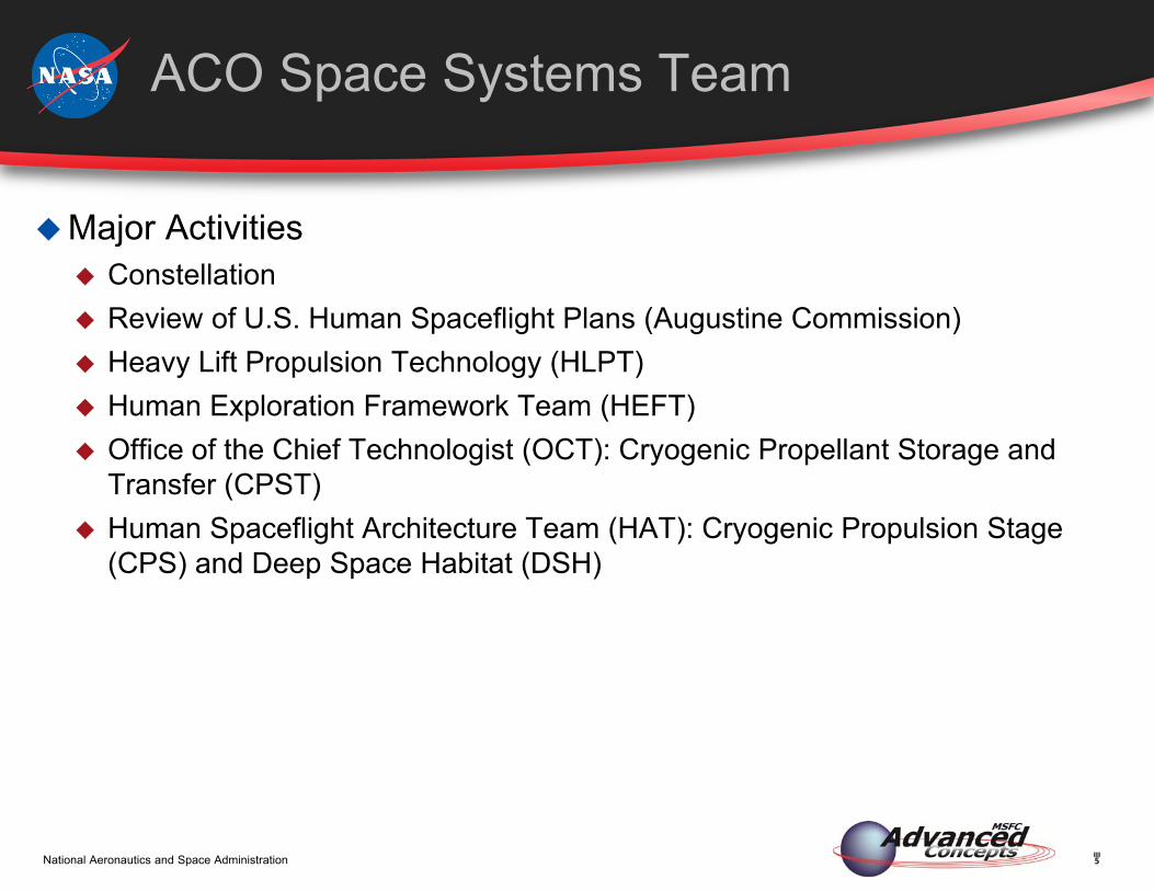
ACO Space Systems Team
Major Activities Constellation Review of U.S. Human Spaceflight Plans (Augustine Commission) Heavy Lift Propulsion Technology (HLPT) Human Exploration Framework Team (HEFT) Office of the Chief Technologist (OCT): Cryogenic Propellant Storage and
Transfer (CPST) Human Spaceflight Architecture Team (HAT): Cryogenic Propulsion Stage
(CPS) and Deep Space Habitat (DSH)
6National Aeronautics and Space Administration
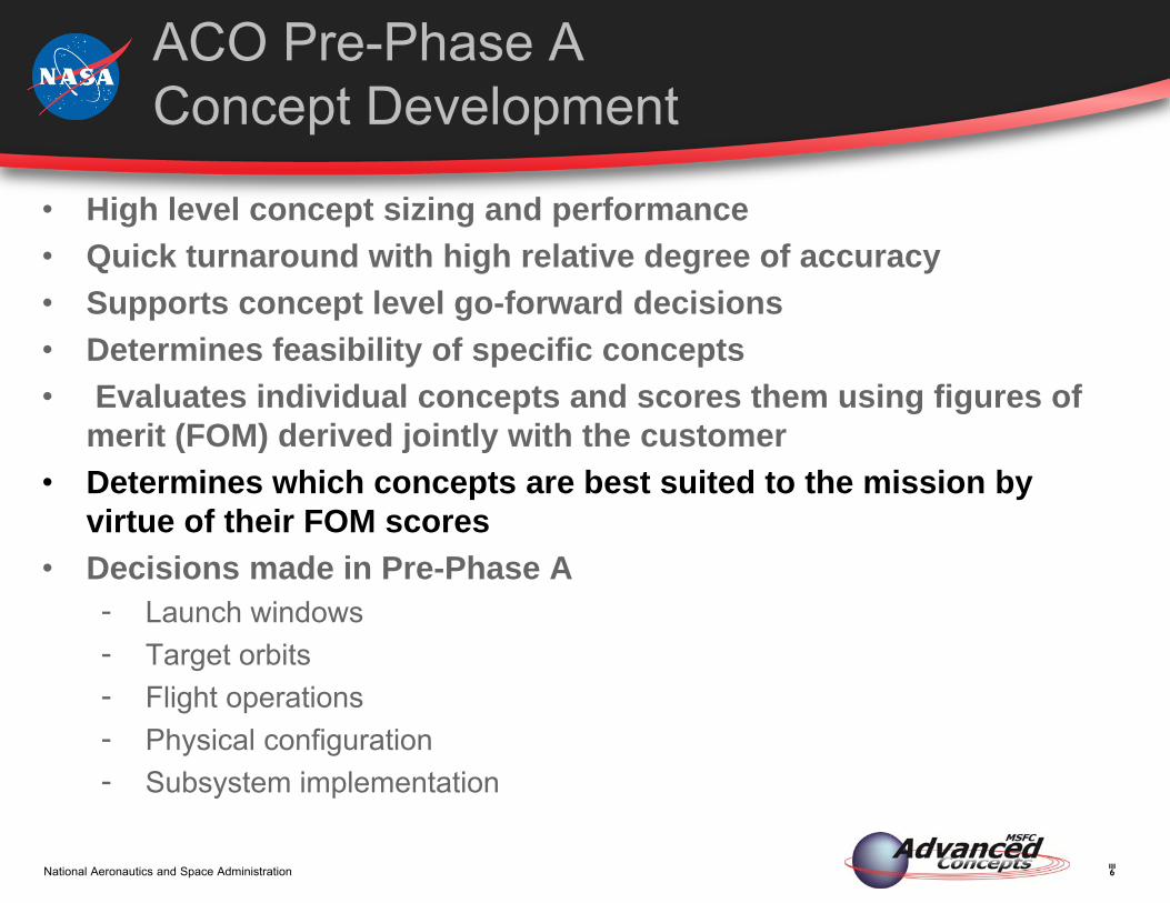
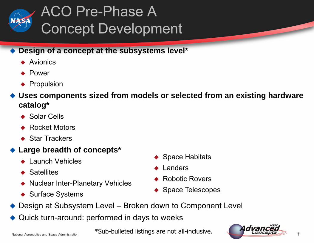
ACO Pre-Phase A Concept Development
• High level concept sizing and performance • Quick turnaround with high relative degree of accuracy• Supports concept level go-forward decisions• Determines feasibility of specific concepts• Evaluates individual concepts and scores them using figures of
merit (FOM) derived jointly with the customer• Determines which concepts are best suited to the mission by
virtue of their FOM scores• Decisions made in Pre-Phase A
- Launch windows- Target orbits- Flight operations- Physical configuration- Subsystem implementation
7National Aeronautics and Space Administration
ACO Pre-Phase A Concept Development
Design of a concept at the subsystems level* Avionics Power Propulsion
Uses components sized from models or selected from an existing hardware catalog* Solar Cells Rocket Motors Star Trackers
Large breadth of concepts* Launch Vehicles Satellites Nuclear Inter-Planetary Vehicles Surface Systems
Design at Subsystem Level – Broken down to Component Level Quick turn-around: performed in days to weeks
*Sub-bulleted listings are not all-inclusive.
Space Habitats Landers Robotic Rovers Space Telescopes
8National Aeronautics and Space Administration
Collaborative Design Process

9National Aeronautics and Space Administration
Systems Analysis
10National Aeronautics and Space Administration
Systems Engineering in ACO
11National Aeronautics and Space Administration
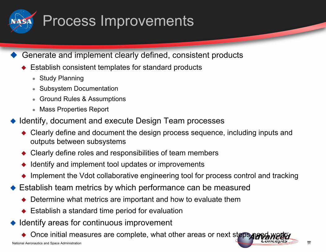
Process Improvements
Generate and implement clearly defined, consistent products Establish consistent templates for standard products
● Study Planning● Subsystem Documentation● Ground Rules & Assumptions● Mass Properties Report
Identify, document and execute Design Team processes Clearly define and document the design process sequence, including inputs and
outputs between subsystems Clearly define roles and responsibilities of team members Identify and implement tool updates or improvements Implement the Vdot collaborative engineering tool for process control and tracking
Establish team metrics by which performance can be measured Determine what metrics are important and how to evaluate them Establish a standard time period for evaluation
Identify areas for continuous improvement Once initial measures are complete, what other areas or next steps need work

12National Aeronautics and Space Administration
Systems Integration
Customer purchased Vdot in late 2011 as part of the process improvement effort
Started training on the tool in early 2012 Began using Vdot for the GR&A on the Wide Field X-ray Telescope Study in
April Next step is to use the tool for the Mass Properties reports Ultimately, all data transfers will be performed and captured in Vdot Benefits of using Vdot
Traceability Planning Discipline Prioritizing Visibility Communication Transparency

13National Aeronautics and Space Administration
Vdot
14National Aeronautics and Space Administration
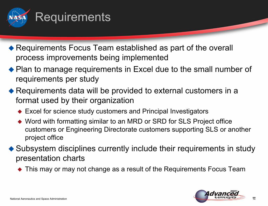
Requirements
Requirements Focus Team established as part of the overall process improvements being implemented
Plan to manage requirements in Excel due to the small number of requirements per study
Requirements data will be provided to external customers in a format used by their organization Excel for science study customers and Principal Investigators Word with formatting similar to an MRD or SRD for SLS Project office
customers or Engineering Directorate customers supporting SLS or another project office
Subsystem disciplines currently include their requirements in study presentation charts This may or may not change as a result of the Requirements Focus Team
15National Aeronautics and Space Administration
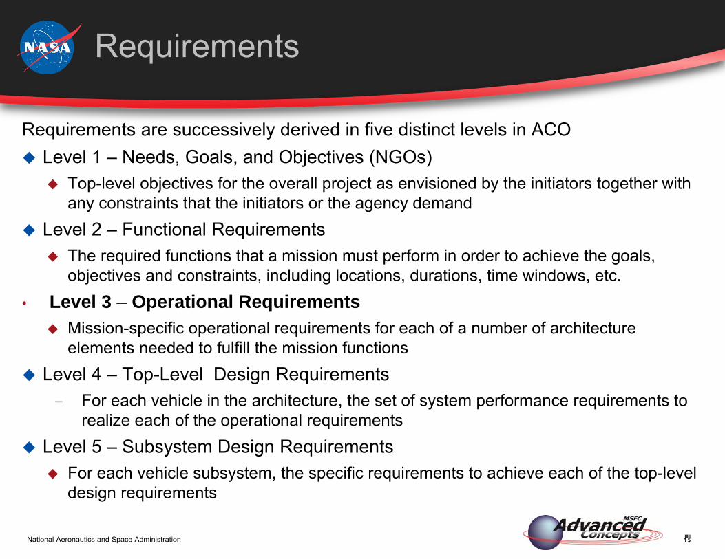
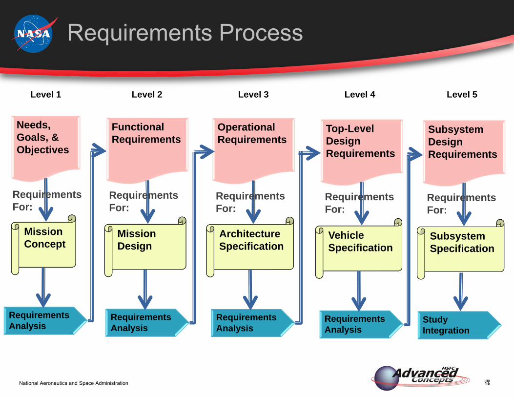
Requirements
Requirements are successively derived in five distinct levels in ACO Level 1 – Needs, Goals, and Objectives (NGOs)
Top-level objectives for the overall project as envisioned by the initiators together with any constraints that the initiators or the agency demand
Level 2 – Functional Requirements The required functions that a mission must perform in order to achieve the goals,
objectives and constraints, including locations, durations, time windows, etc.• Level 3 – Operational Requirements
Mission-specific operational requirements for each of a number of architecture elements needed to fulfill the mission functions
Level 4 – Top-Level Design Requirements− For each vehicle in the architecture, the set of system performance requirements to
realize each of the operational requirements Level 5 – Subsystem Design Requirements
For each vehicle subsystem, the specific requirements to achieve each of the top-level design requirements
16National Aeronautics and Space Administration
Requirements Process
Needs, Goals, & Objectives
Mission Concept
Requirements Analysis
Functional Requirements
Mission Design
Requirements Analysis
Operational Requirements
Architecture Specification
Requirements Analysis
Top-Level Design Requirements
Vehicle Specification
Requirements Analysis
Subsystem Design Requirements
Subsystem Specification
Level 1 Level 2 Level 3 Level 4 Level 5
Study Integration
RequirementsFor:
RequirementsFor:
RequirementsFor:
RequirementsFor:
RequirementsFor:
17National Aeronautics and Space Administration
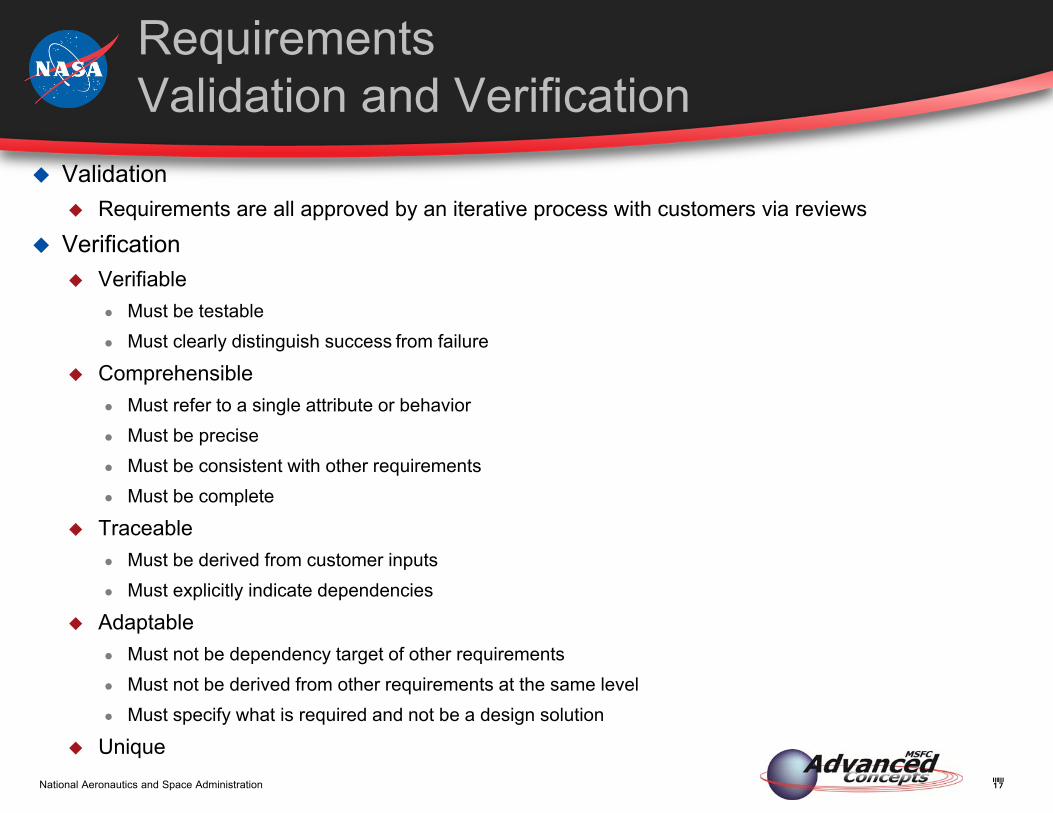
Requirements Validation and Verification
Validation Requirements are all approved by an iterative process with customers via reviews
Verification Verifiable
● Must be testable● Must clearly distinguish success from failure
Comprehensible● Must refer to a single attribute or behavior● Must be precise● Must be consistent with other requirements● Must be complete
Traceable● Must be derived from customer inputs● Must explicitly indicate dependencies
Adaptable● Must not be dependency target of other requirements● Must not be derived from other requirements at the same level● Must specify what is required and not be a design solution
Unique
18National Aeronautics and Space Administration
Risk Management at NASA is guided by specification NPR 8000.4A This specification defines Risk Management as
Risk Informed Decision Making (RIDM) Continuous Risk Management
Many NASA Announcements of Opportunity specifically demand Risk Assessment as a part of proposal response
In addition, Risk Assessment is often requested by internal customers
Risk Analysis in Pre-Phase A Design

19National Aeronautics and Space Administration
Unnecessary Seen as contrary to a ‘Can Do’ attitude Negative views of Risk Analysis obscure benefits
Time Consuming, Expensive Past risk identification methods often required significant effort Feeling at NASA that Risk Analysis is a cost to be avoided until after ATP
when down-selected concept is detailed
Low Fidelity of Risk Likelihood, Impact Prevalence of poor risk evaluation methods has led to common belief that risk
estimates cannot be made with any accuracy before design is complete Confusion of Risk with Reliability leads to conclusion that only very high
fidelity risk estimates are useful
Reluctance to use Risk Analysis in Pre-Phase A
20National Aeronautics and Space Administration
Define Pre-Phase A Risk Analysis and Management Requirements Must support RIDM for Pre-Phase A decisions Must be quick and easy to implement Must be adaptable to a wide variety of concepts Must be capable of producing a Risk Plan useful for further studies (continuous risk
management) Tailor Risk Analysis to the specific needs of Pre-Phase A work
Start by viewing risk in the context of the decisions that we make in Pre-Phase A studies. The appropriate risks are always found in the specific uncertainties that affect those decisions
Identify as many risks as possible by inspecting those decisions. Taxonomy-based risk identification does this well
Estimate the Risk Probability and Impact using historical data along with expert judgment. Estimates must be sufficient to inform Pre-Phase A decisions but will not have the fidelity available at Phase C and beyond
Use automated tools to reduce cost and improve standardization
What To Do?
21National Aeronautics and Space Administration
Advanced Concepts Evaluating Risk Tool (ACERT)
The ESTS Group within ACO took the initiative to develop a risk tool tailored to Pre-Phase A
Tool was validated by ESTS risk experts from EV ACERT was verified by using the tool on two studies using other risk
identification methods and comparing the results A conference paper, “Risk Evaluation in the Pre-Phase A Conceptual Design of
Spacecraft” was presented at the AIAA Space 2010 Funding and resource limitations have prevented the development of formal
documentation and tool maintenance Forward Work Needed
Addition of rules to identify more operations risks Creation of more detailed risk statement templates Tool Maintenance Documentation
22National Aeronautics and Space Administration
ACERT
Taxonomy/source – based risk identification tool Taxonomy-based risk identification searches the risk space by the source of
uncertainty Value-based risk assessment assigns a comparable value to each risk
Computes risk probability based on empirical data, expert judgment Computes impact value based on value (cost in $) of risk event occurrence
Risk Value = Probability × Impact Excel workbook-based interface Allows input of mission, operations, and design concept information, including the
concept WBS Excel macro launches a rule-based (backward-chaining) system
Asks each discipline expert a series of questions about the mission or concept design The answers are used to identify risks
Risk suggestions may be edited in Excel and scored with VBA custom formula functions
Tool may be customized by editing risk identification rules, risk statement templates, and other configuration information
23National Aeronautics and Space Administration
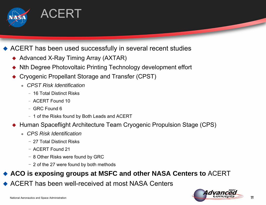
ACERT
ACERT has been used successfully in several recent studies Advanced X-Ray Timing Array (AXTAR) Nth Degree Photovoltaic Printing Technology development effort Cryogenic Propellant Storage and Transfer (CPST)
● CPST Risk Identification− 16 Total Distinct Risks− ACERT Found 10− GRC Found 6− 1 of the Risks found by Both Leads and ACERT
Human Spaceflight Architecture Team Cryogenic Propulsion Stage (CPS)● CPS Risk Identification
− 27 Total Distinct Risks − ACERT Found 21− 8 Other Risks were found by GRC − 2 of the 27 were found by both methods
ACO is exposing groups at MSFC and other NASA Centers to ACERT ACERT has been well-received at most NASA Centers
24National Aeronautics and Space Administration
Useful Figure of Merit in evaluating Concept Design Decisions (e.g. choice of Rocket Motor)
Figure of Merit in choosing ‘Go-Forward’ concept in trade studies Informs the planning of the crucial Phase A study Guides Project Management in allocating resources to solve potential
problems early
Benefits of Risk Analysis in Pre-Phase A Design
25National Aeronautics and Space Administration
Conclusion
Systems Engineering is about the implementation of processes that assure that the customer’s NGOs are met throughout the engineering product lifecycle
ACO is currently engaged in an effort to implement those processes The Pre-Phase A engineering environment represents the very beginning of that
product life-cycle, and presents a number of unique challenges that affect systems engineering implementation
Current experience suggests that by tailoring traditional systems engineering processes to the specific demands of the unique environment, ACO is able to realize the full benefits of systems engineering and provide a product that better prepares the customer for Phase A and beyond Integration: Vdot Requirements: Group requirements according to the ACO study flow Risk: Use semi-automated tools to implement taxonomy-based risk
identification and value-based risk assessment processes that require less time and effort

National Aeronautics and Space Administration www.nasa.gov


![Vol. 7, No. 7, 2016 Goal Model Integration for Tailoring ... · Again, tailoring of development processes for product lines is an important success factor. As described in [13] but](https://img.dokumen.tips/doc/110x75/602d3b78b056a8524613474f/vol-7-no-7-2016-goal-model-integration-for-tailoring-again-tailoring-of.jpg)


