Embed Size (px)
Citation preview

Table of ContentsEntire NEC®, Article
All. . . . . . . . . . . . . . . . . . . . . . . . . . . . . . . . . . . . . . . . . . . . . . . . . . . . . 3General . . . . . . . . . . . . . . . . . . . . . . . . . . . . . . . . . . . . . . . . . . . . . . . . 4
Administration and Enforcement, Article 8080 Introduction . . . . . . . . . . . . . . . . . . . . . . . . . . . . . . . . . . . . . . . . . . . . . 5
Introduction and Enforcement, Article 9090 Introduction . . . . . . . . . . . . . . . . . . . . . . . . . . . . . . . . . . . . . . . . . . . . . 6
General, Articles 100 and 110100 Definitions . . . . . . . . . . . . . . . . . . . . . . . . . . . . . . . . . . . . . . . . . . . . . . 7110 Requirements for Electrical Installations . . . . . . . . . . . . . . . . . . . . . . . 8
Wiring and Protection, Articles 200-250200 Use and Identification of Grounded Conductors . . . . . . . . . . . . . . . . 10210 Branch Circuits . . . . . . . . . . . . . . . . . . . . . . . . . . . . . . . . . . . . . . . . . 11225 Outside Branch Circuits and Feeders . . . . . . . . . . . . . . . . . . . . . . . . 17230 Services. . . . . . . . . . . . . . . . . . . . . . . . . . . . . . . . . . . . . . . . . . . . . . . 18250 Grounding and Bonding. . . . . . . . . . . . . . . . . . . . . . . . . . . . . . . . . . . 19
Wiring Methods and Materials, Articles 300-392300 Wiring Methods . . . . . . . . . . . . . . . . . . . . . . . . . . . . . . . . . . . . . . . . . 29310 Conductors for General Wiring . . . . . . . . . . . . . . . . . . . . . . . . . . . . . 40312 Cabinets, Cutout Boxes and Meter Socket Enclosures. . . . . . . . . . . 41314 Outlet, Device, Pull and Junction Boxes:
Conduit Bodies, Fittings and Handhole Enclosures . . . . . . . . . . . . . 42342 Intermediate Metal Conduit: Type IMC . . . . . . . . . . . . . . . . . . . . . . . 48344 Rigid Metal Conduit: Type RMC . . . . . . . . . . . . . . . . . . . . . . . . . . . . 51348 Flexible Metal Conduit: Type FMC . . . . . . . . . . . . . . . . . . . . . . . . . . 54350 Liquidtight Flexible Metal Conduit: Type LFMC. . . . . . . . . . . . . . . . . 58352 Rigid Nonmetallic Conduit: Type RNC. . . . . . . . . . . . . . . . . . . . . . . . 61353 High Density Polyethylene Conduit: Type HDPE . . . . . . . . . . . . . . . 62356 Liquidtight Flexible Nonmetallic Conduit: Type LFNC . . . . . . . . . . . . 63358 Electrical Metallic Tubing: Type EMT. . . . . . . . . . . . . . . . . . . . . . . . . 69362 Electrical Nonmetallic Tubing: Type ENT . . . . . . . . . . . . . . . . . . . . . 71374 Cellular Metal Floor Raceways . . . . . . . . . . . . . . . . . . . . . . . . . . . . . 73376 Metal Wireways . . . . . . . . . . . . . . . . . . . . . . . . . . . . . . . . . . . . . . . . . 74384 Strut-Type Channel Raceway . . . . . . . . . . . . . . . . . . . . . . . . . . . . . . 75386 Surface Metal Raceways. . . . . . . . . . . . . . . . . . . . . . . . . . . . . . . . . . 76388 Surface Nonmetallic Raceways. . . . . . . . . . . . . . . . . . . . . . . . . . . . . 79390 Underfloor Raceways . . . . . . . . . . . . . . . . . . . . . . . . . . . . . . . . . . . . 81392 Cable Trays . . . . . . . . . . . . . . . . . . . . . . . . . . . . . . . . . . . . . . . . . . . . 82
Equipment for General Use, Articles 404-440404 Switches . . . . . . . . . . . . . . . . . . . . . . . . . . . . . . . . . . . . . . . . . . . . . . 89406 Receptacles, Cord Connectors and Attachment Plugs (Caps) . . . . . 90409 Industrial Control Panels . . . . . . . . . . . . . . . . . . . . . . . . . . . . . . . . . . 94
© 2005 Thomas & Betts Corporation. Specifications are subject to change without notice. www.tnb.com 1
410 Luminaires (Lighting Fixtures), Lampholders and Lamps . . . . . . . . . 95422 Appliances. . . . . . . . . . . . . . . . . . . . . . . . . . . . . . . . . . . . . . . . . . . . . 97430 Motors, Motor Circuits and Controllers . . . . . . . . . . . . . . . . . . . . . . . 98440 Air-Conditioning and Refrigeration Equipment . . . . . . . . . . . . . . . . 100
Special Occupancies, Articles 500-590500 Hazardous Classified Locations, Classes
I, II & III, Division 1 & 2 . . . . . . . . . . . . . . . . . . . . . . . . . . . . . . . . . . 101501 Class I Locations . . . . . . . . . . . . . . . . . . . . . . . . . . . . . . . . . . . . . . . 102502 Class II Locations . . . . . . . . . . . . . . . . . . . . . . . . . . . . . . . . . . . . . . 105506 Zone 20, 21 and 22 Locations for Flammable Dusts,
Fibers and Flyings . . . . . . . . . . . . . . . . . . . . . . . . . . . . . . . . . . . . . . 106516 Spray Application, Dipping, and Coating Processes . . . . . . . . . . . . 107517 Health Care Facilities . . . . . . . . . . . . . . . . . . . . . . . . . . . . . . . . . . . 108518 Assembly Occupancies . . . . . . . . . . . . . . . . . . . . . . . . . . . . . . . . . . 109520 Theatres, Audience Areas of Motion Picture and
Television Studios, Performance Areas,and Similar Locations . . . . . . . . . . . . . . . . . . . . . . . . . . . . . . . . . . . 110
547 Agricultural Buildings . . . . . . . . . . . . . . . . . . . . . . . . . . . . . . . . . . . . 111551 Recreational Vehicles and Recreational
Vehicle Parks . . . . . . . . . . . . . . . . . . . . . . . . . . . . . . . . . . . . . . . . . . 113590 Temporary Installations . . . . . . . . . . . . . . . . . . . . . . . . . . . . . . . . . . 114
Special Equipment, Articles 604-830604 Manufactured Wiring Systems. . . . . . . . . . . . . . . . . . . . . . . . . . . . . 115680 Swimming Pools, Fountains, and Similar Installations . . . . . . . . . . 117690 Solar Photovoltaic Systems. . . . . . . . . . . . . . . . . . . . . . . . . . . . . . . 120695 Fire Pumps . . . . . . . . . . . . . . . . . . . . . . . . . . . . . . . . . . . . . . . . . . . 121725 Class 1, Class 2, and Class 3 Remote-Control,
Signaling, and Power-Limited Circuits. . . . . . . . . . . . . . . . . . . . . . . 123770 Optical Fiber Cables and Raceways . . . . . . . . . . . . . . . . . . . . . . . . 124800 Communications Circuits. . . . . . . . . . . . . . . . . . . . . . . . . . . . . . . . . 125820 Community Antenna Television and Radio
Distribution Systems . . . . . . . . . . . . . . . . . . . . . . . . . . . . . . . . . . . . 127830 Network-Powered Broadband Communications
Systems. . . . . . . . . . . . . . . . . . . . . . . . . . . . . . . . . . . . . . . . . . . . . . 128
On the following pages are changes to the National Electrical Code for the 2005Code cycle. This is not intended to be an iteration of all the changes, but a listing ofthose that may affect the Thomas & Betts product lines.
This document was compiled through the efforts of the Technical LiaisonDepartment of Thomas & Betts, and is the property of Thomas & Betts. If you haveany questions or require interpretation assistance please contact one of thefollowing:
Tim McNeive 1-800-888-0211 Ext. 5785Greg Steinman 1-800-888-0211 Ext. 5719George Dauberger 1-800-888-0211 Ext. 5191
Do not duplicate any part of this publication without the permission of a member ofthe T&B Technical Liaison Department.
2 © 2005 Thomas & Betts Corporation. Specifications are subject to change without notice. www.tnb.com
Article - Entire NEC®
T&B PRODUCT: All
Section Entire NEC
ANALYSIS OF CHANGE:The phrase “Listed for thepurpose” has been removedfrom the NEC and replacedwith “Listed as ____”. Thisprovides users more guidance on the proper application of Listedproducts. Annex A of the NEC includes a list of Product SafetyStandards for reference. An example would be products listed as“grounding and bonding equipment” as opposed to “listed for thepurpose”.
© 2005 Thomas & Betts Corporation. Specifications are subject to change without notice. www.tnb.com 3
NEC 2005 © National Fire Protection Association
Article - Entire NEC®
T&B PRODUCT: General
Section Entire NEC
There was a proposal to change the term “equipment groundingconductor” to “equipment bonding conductor”. This change wasplaced on HOLD until the 2008 NEC cycle.
ANALYSIS OF CHANGE: This would be a major change thatwould have impacted almost every article. A task group has beenformed to evaluate this proposal. There is a group that believesthat the term “equipment bonding conductor” is technically morecorrect since the attachment of that conductor does not directlyconnect to the ground.
From Article 100, the definitions are:
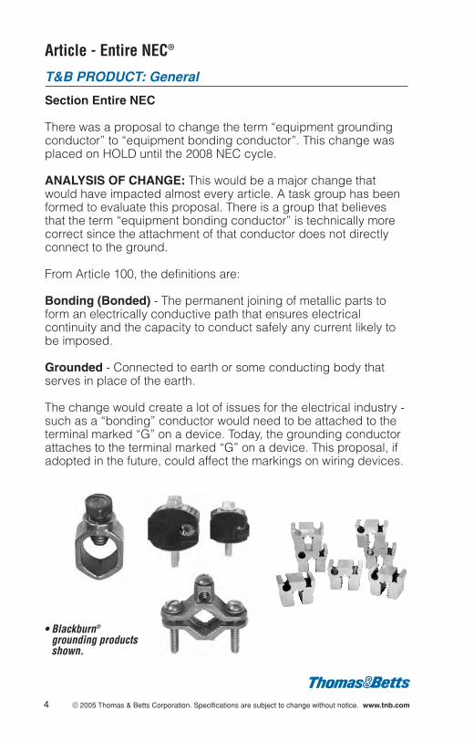
Bonding (Bonded) - The permanent joining of metallic parts toform an electrically conductive path that ensures electricalcontinuity and the capacity to conduct safely any current likely tobe imposed.
Grounded - Connected to earth or some conducting body thatserves in place of the earth.
The change would create a lot of issues for the electrical industry -such as a “bonding” conductor would need to be attached to theterminal marked “G” on a device. Today, the grounding conductorattaches to the terminal marked “G” on a device. This proposal, ifadopted in the future, could affect the markings on wiring devices.
4 © 2005 Thomas & Betts Corporation. Specifications are subject to change without notice. www.tnb.com
• Blackburn®
grounding productsshown.
Article 80 - Administration and Enforcement
T&B PRODUCT: All
Entire Article Administration and Enforcement
Article 80 has been relocated as ANNEX G. It is an example ofadministrative and enforcement requirements and is not part of thecode unless specifically adopted.
ANALYSIS OF CHANGE: For information only. These informativeguidelines provide insight into the means by which the NEC® isadministered and enforced locally.
© 2005 Thomas & Betts Corporation. Specifications are subject to change without notice. www.tnb.com 5
NEC 2005 © National Fire Protection Association
Article 90 - Introduction
T&B PRODUCT: All
Section 90.1 (D) Purpose; Relation to other InternationalStandards
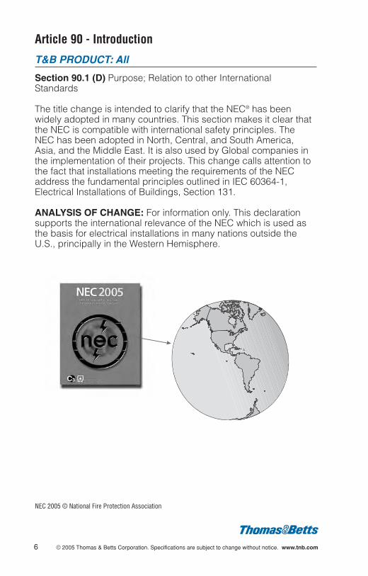
The title change is intended to clarify that the NEC® has beenwidely adopted in many countries. This section makes it clear thatthe NEC is compatible with international safety principles. TheNEC has been adopted in North, Central, and South America,Asia, and the Middle East. It is also used by Global companies inthe implementation of their projects. This change calls attention tothe fact that installations meeting the requirements of the NECaddress the fundamental principles outlined in IEC 60364-1,Electrical Installations of Buildings, Section 131.
ANALYSIS OF CHANGE: For information only. This declarationsupports the international relevance of the NEC which is used asthe basis for electrical installations in many nations outside theU.S., principally in the Western Hemisphere.
6 © 2005 Thomas & Betts Corporation. Specifications are subject to change without notice. www.tnb.com
NEC 2005 © National Fire Protection Association
Article 100 - Definitions
T&B PRODUCT: Grounding
Section 100 (I) General
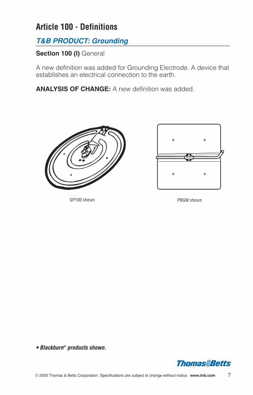
A new definition was added for Grounding Electrode. A device thatestablishes an electrical connection to the earth.
ANALYSIS OF CHANGE: A new definition was added.
© 2005 Thomas & Betts Corporation. Specifications are subject to change without notice. www.tnb.com 7
GP100 shown PBGW shown
• Blackburn® products shown.
Article 110 - Requirements for Electrical Installations
T&B PRODUCT: All
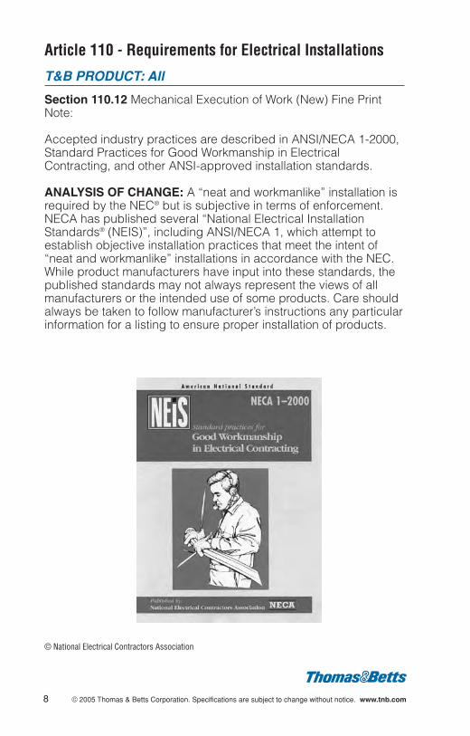
Section 110.12 Mechanical Execution of Work (New) Fine PrintNote:
Accepted industry practices are described in ANSI/NECA 1-2000,Standard Practices for Good Workmanship in ElectricalContracting, and other ANSI-approved installation standards.
ANALYSIS OF CHANGE: A “neat and workmanlike” installation isrequired by the NEC® but is subjective in terms of enforcement.NECA has published several “National Electrical InstallationStandards® (NEIS)”, including ANSI/NECA 1, which attempt toestablish objective installation practices that meet the intent of“neat and workmanlike” installations in accordance with the NEC.While product manufacturers have input into these standards, thepublished standards may not always represent the views of allmanufacturers or the intended use of some products. Care shouldalways be taken to follow manufacturer’s instructions any particularinformation for a listing to ensure proper installation of products.
8 © 2005 Thomas & Betts Corporation. Specifications are subject to change without notice. www.tnb.com
© National Electrical Contractors Association
Article 110 - Requirements for Electrical Installations(Continued)
T&B PRODUCT: Electrical Connectors, UndergroundSplices, Heat Shrinkable Tubing
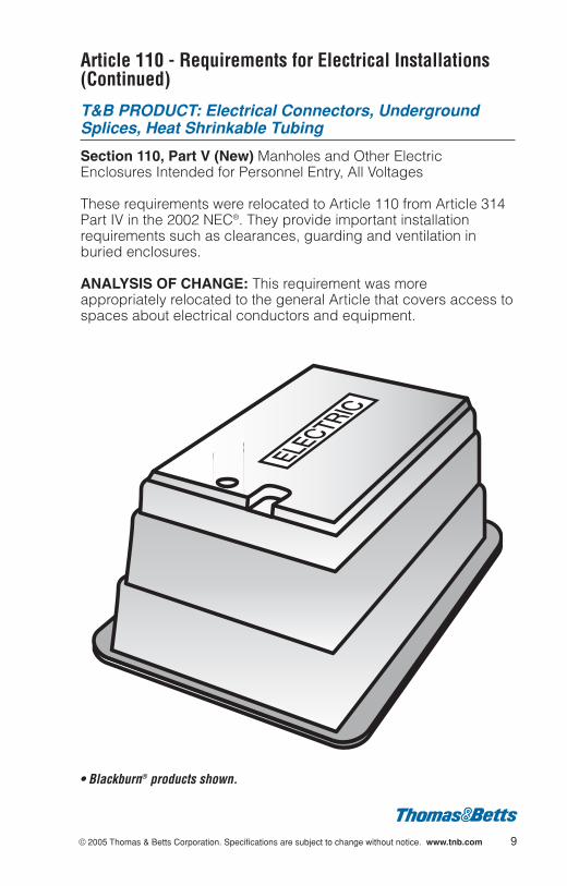
Section 110, Part V (New) Manholes and Other ElectricEnclosures Intended for Personnel Entry, All Voltages
These requirements were relocated to Article 110 from Article 314Part IV in the 2002 NEC®. They provide important installationrequirements such as clearances, guarding and ventilation inburied enclosures.
ANALYSIS OF CHANGE: This requirement was moreappropriately relocated to the general Article that covers access tospaces about electrical conductors and equipment.
© 2005 Thomas & Betts Corporation. Specifications are subject to change without notice. www.tnb.com 9
• Blackburn® products shown.
Article 200 - Use and Identification of GroundedConductors
T&B PRODUCT: Identification Products
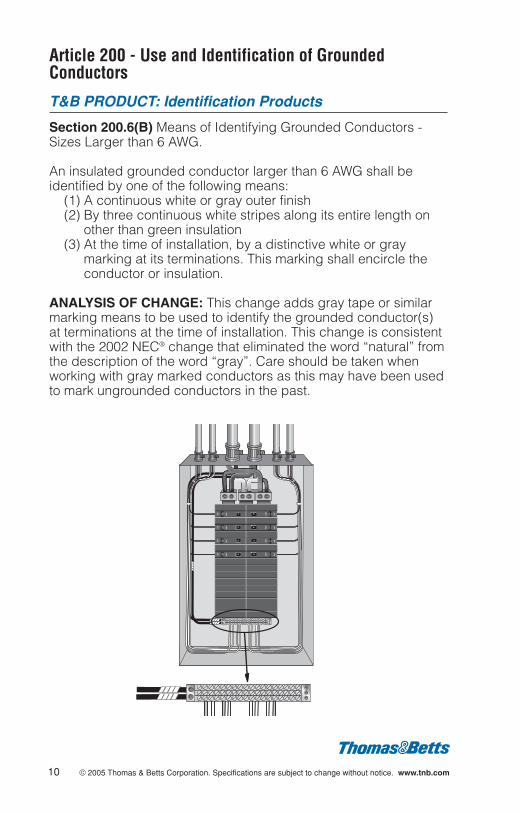
Section 200.6(B) Means of Identifying Grounded Conductors -Sizes Larger than 6 AWG.
An insulated grounded conductor larger than 6 AWG shall beidentified by one of the following means:
(1) A continuous white or gray outer finish(2) By three continuous white stripes along its entire length on
other than green insulation(3) At the time of installation, by a distinctive white or gray
marking at its terminations. This marking shall encircle theconductor or insulation.
ANALYSIS OF CHANGE: This change adds gray tape or similarmarking means to be used to identify the grounded conductor(s)at terminations at the time of installation. This change is consistentwith the 2002 NEC® change that eliminated the word “natural” fromthe description of the word “gray”. Care should be taken whenworking with gray marked conductors as this may have been usedto mark ungrounded conductors in the past.
10 © 2005 Thomas & Betts Corporation. Specifications are subject to change without notice. www.tnb.com

Article 210 - Branch Circuits
T&B PRODUCT: Outdoor Weatherproof Boxes & Covers
Section 210.8 (B)(4) (New) Ground-Fault Circuit InterrupterProtection for Personnel; Other Than Dwelling Units
Added the term “Outdoors in public spaces- for the purposes ofthis section a public space is defined as any space that is for useby or is accessible to the public” to the list of areas that shall haveground-fault circuit interrupter protection for personnel.
ANALYSIS OF CHANGE: This expanded requirement for GFCIprotected receptacles outdoors will influence the demand for thesize and type of boxes and weatherproof while-in-use covers inpublic places such as schools, stores, theaters, shopping malls,restaurants, museums, houses of worship, and other commercialand government structures, along sidewalks, plazas, parks,promenades, etc.
© 2005 Thomas & Betts Corporation. Specifications are subject to change without notice. www.tnb.com 11
• Red•Dot ® weatherproof products shown.

Article 210 - Branch Circuits (Continued)
T&B PRODUCT: Outdoor Weatherproof Boxes & Covers
Section 210.8 (B)(5) (New) Ground-Fault Circuit InterrupterProtection for Personnel; Other Than Dwelling Units
Added the term “Outdoors, where installed to comply with 210.63”to the list of areas that shall have ground-fault circuit interrupterprotection for personnel. This requires the receptacle outletinstalled in accordance with 210.63, to be within 25 feet of heating,air-conditioning and refrigeration units, and to be equipped withground-fault circuit-interrupter protection for personnel.
ANALYSIS OF CHANGE: Another expansion of GFCI protectionwith the potential for influence on the demand for the size and typeof box and weatherproof while-in-use covers.
12 © 2005 Thomas & Betts Corporation. Specifications are subject to change without notice. www.tnb.com
Article 210 - Branch Circuits (Continued)
T&B PRODUCT: Outdoor Weatherproof Boxes & Covers
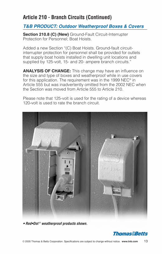
Section 210.8 (C) (New) Ground-Fault Circuit-InterrupterProtection for Personnel; Boat Hoists.
Added a new Section “(C) Boat Hoists. Ground-fault circuit-interrupter protection for personnel shall be provided for outletsthat supply boat hoists installed in dwelling unit locations andsupplied by 125-volt, 15- and 20- ampere branch circuits.”
ANALYSIS OF CHANGE: This change may have an influence onthe size and type of boxes and weatherproof while in use coversfor this application. The requirement was in the 1999 NEC® inArticle 555 but was inadvertently omitted from the 2002 NEC whenthe Section was moved from Article 555 to Article 210.
Please note that 125-volt is used for the rating of a device whereas120-volt is used to rate the branch circuit.
© 2005 Thomas & Betts Corporation. Specifications are subject to change without notice. www.tnb.com 13
• Red•Dot ® weatherproof products shown.

Article 210 - Branch Circuits (Continued)
T&B PRODUCT: Circuit Breakers
Section 210.12 (B) Arc-Fault Circuit-Interrupter Protection;Dwelling Unit Bedrooms
The revision to this Section mandates the use of a “combinationtype” AFCI to the exclusion of branch/feeder types,” beginningJanuary 1, 2008.
ANALYSIS OF CHANGE: The requirement for AFCI protection inbedrooms of dwelling units became effective January 1, 2002.Presently, AFCI protection is of the branch/feeder type. Listedcombination types were not commercially available at the time theproposal for this change was considered by the NEC® CodeMaking panel. A transition period of 3 years is established toenable the technology to advance to the market.
There are two AFCI types to be considered: (1) Branch/FeederType and (2) Combination Type.
(1) AFCI Branch/Feeder Type (Commercially Available): Offersprotection to the branch circuit or to the feeder circuit, butonly limited protection to extension and appliance wiring(connected cords of utilization equipment).
(2) AFCI Combination Type (Not Commercially Available): Offersprotection to the branch circuit or to the feeder circuit andalso to any connecting cords of utilization equipment.
AFCI-
Combination-
Type
14 © 2005 Thomas & Betts Corporation. Specifications are subject to change without notice. www.tnb.com

Article 210 - Branch Circuits (Continued)
T&B PRODUCT: Outlet Boxes and Fittings
Section 210.52(C)(1)(New Exception) Dwelling Unit ReceptacleOutlets; Countertops; Wall Counter Spaces
A new exception and diagrams have been added to clarify howseparate wall countertop spaces are determined and to clarifywhere outlets are and are not required.
ANALYSIS OF CHANGE: This change may result in the need foradditional receptacle outlets on wall counters as outlets placedwithin the areas designated “outlets not required”, “shall not beconsidered as the required countertop outlets.”
© 2005 Thomas & Betts Corporation. Specifications are subject to change without notice. www.tnb.com 15

Article 210 - Branch Circuits (Continued)
T&B PRODUCT: Outlet Boxes and Fittings
Section 210.52(C)(2) Dwelling Unit Receptacle Outlets;Countertop; Island Counter Spaces
New text has been added to clarify how separate countertopspaces are determined on Island Countertops. “Where a rangetopor sink is installed in an island counter, and the width of thecounter behind the rangetop or sink is less than 300 mm (12 in.),the rangetop or sink is considered to divide the island into twoseparate countertop spaces as defined in 210.52(C)(4).”
ANALYSIS OF CHANGE: This change results in the need foradditional receptacle outlets on certain island countertop designs.Since each side of the countertop is determined to be a separatecountertop space and a separate receptacle outlet is required foreach space 12 inches or wider.
16 © 2005 Thomas & Betts Corporation. Specifications are subject to change without notice. www.tnb.com
Article 225
T&B PRODUCT: Raceways, Fittings, Boxes
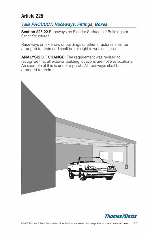
Section 225.22 Raceways on Exterior Surfaces of Buildings orOther Structures
Raceways on exteriors of buildings or other structures shall bearranged to drain and shall be raintight in wet locations.
ANALYSIS OF CHANGE: The requirement was revised torecognize that all exterior building locations are not wet locations.An example of this is under a porch. All raceways shall bearranged to drain.
© 2005 Thomas & Betts Corporation. Specifications are subject to change without notice. www.tnb.com 17
Article 230 - Services
T&B PRODUCT: Cable Tray
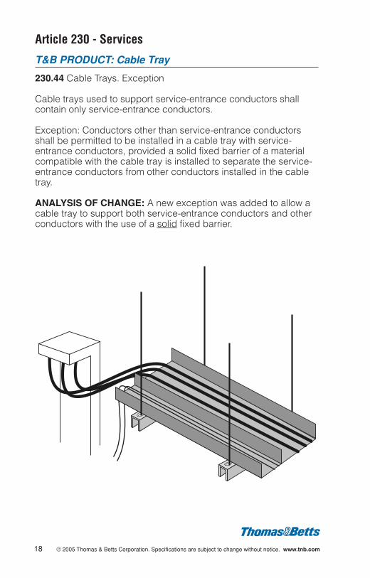
230.44 Cable Trays. Exception
Cable trays used to support service-entrance conductors shallcontain only service-entrance conductors.
Exception: Conductors other than service-entrance conductorsshall be permitted to be installed in a cable tray with service-entrance conductors, provided a solid fixed barrier of a materialcompatible with the cable tray is installed to separate the service-entrance conductors from other conductors installed in the cabletray.
ANALYSIS OF CHANGE: A new exception was added to allow acable tray to support both service-entrance conductors and otherconductors with the use of a solid fixed barrier.
18 © 2005 Thomas & Betts Corporation. Specifications are subject to change without notice. www.tnb.com
© 2005 Thomas & Betts Corporation. Specifications are subject to change without notice. www.tnb.com 19
Article 250 - Grounding and Bonding
T&B PRODUCT: General
Section Title
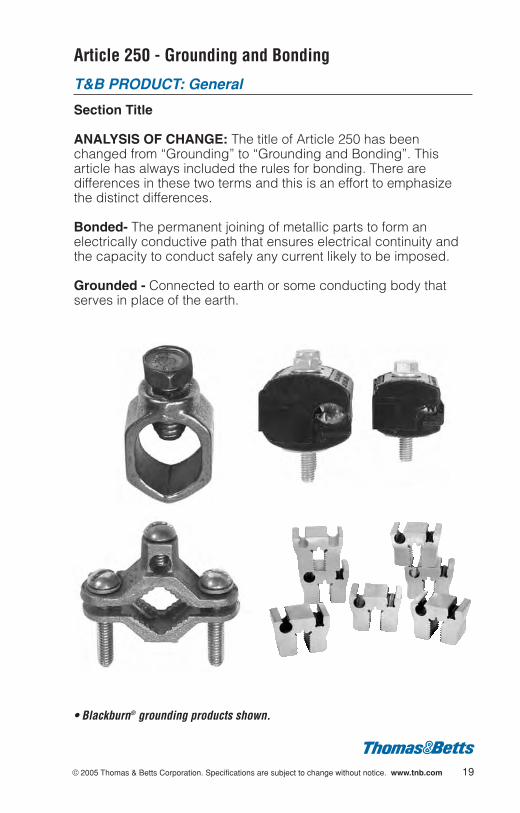
ANALYSIS OF CHANGE: The title of Article 250 has beenchanged from “Grounding” to “Grounding and Bonding”. Thisarticle has always included the rules for bonding. There aredifferences in these two terms and this is an effort to emphasizethe distinct differences.
Bonded- The permanent joining of metallic parts to form anelectrically conductive path that ensures electrical continuity andthe capacity to conduct safely any current likely to be imposed.
Grounded - Connected to earth or some conducting body thatserves in place of the earth.
• Blackburn® grounding products shown.

Article 250 - Grounding and Bonding (Continued)
T&B PRODUCT: Grounding Products, Terminals
Section 250.8 Connection of Grounding and Bonding Equipment
Sheet metal screws shall not be used to connect groundingconductors or connection devices to enclosures.
ANALYSIS OF CHANGE: The revised text adds the term “orconnection devices” and disallows the attachment of connectiondevices with sheet metal screws. The connection issue is with thesheet metal screw and its tendency to loosen over time.
20 © 2005 Thomas & Betts Corporation. Specifications are subject to change without notice. www.tnb.com
© 2005 Thomas & Betts Corporation. Specifications are subject to change without notice. www.tnb.com 21
Article 250 - Grounding and Bonding (Continued)
T&B PRODUCT: Electrical Connectors
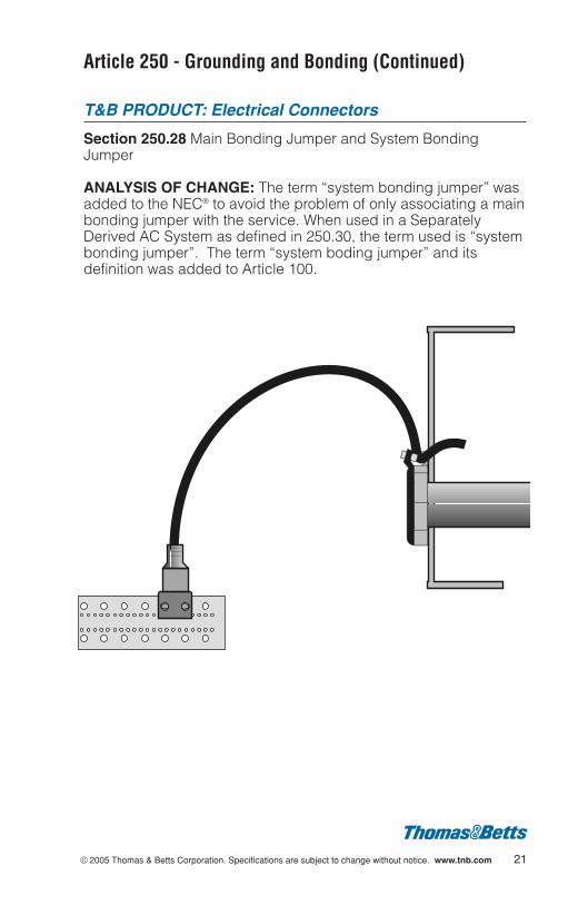
Section 250.28 Main Bonding Jumper and System BondingJumper
ANALYSIS OF CHANGE: The term “system bonding jumper” wasadded to the NEC® to avoid the problem of only associating a mainbonding jumper with the service. When used in a SeparatelyDerived AC System as defined in 250.30, the term used is “systembonding jumper”. The term “system boding jumper” and itsdefinition was added to Article 100.
Article 250 - Grounding and Bonding (Continued)
T&B PRODUCT: Electrical Connectors
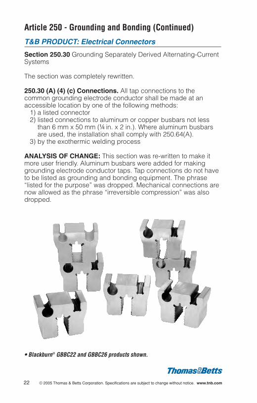
Section 250.30 Grounding Separately Derived Alternating-CurrentSystems
The section was completely rewritten.
250.30 (A) (4) (c) Connections. All tap connections to thecommon grounding electrode conductor shall be made at anaccessible location by one of the following methods:
1) a listed connector 2) listed connections to aluminum or copper busbars not less
than 6 mm x 50 mm (b in. x 2 in.). Where aluminum busbarsare used, the installation shall comply with 250.64(A).
3) by the exothermic welding process
ANALYSIS OF CHANGE: This section was re-written to make itmore user friendly. Aluminum busbars were added for makinggrounding electrode conductor taps. Tap connections do not haveto be listed as grounding and bonding equipment. The phrase“listed for the purpose” was dropped. Mechanical connections arenow allowed as the phrase “irreversible compression” was alsodropped.
• Blackburn® GBBC22 and GBBC26 products shown.
22 © 2005 Thomas & Betts Corporation. Specifications are subject to change without notice. www.tnb.com
Article 250 - Grounding and Bonding (Continued)
T&B PRODUCT: Electrical Connectors
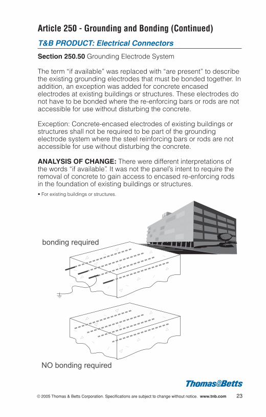
Section 250.50 Grounding Electrode System
The term “if available” was replaced with “are present” to describethe existing grounding electrodes that must be bonded together. Inaddition, an exception was added for concrete encasedelectrodes at existing buildings or structures. These electrodes donot have to be bonded where the re-enforcing bars or rods are notaccessible for use without disturbing the concrete.
Exception: Concrete-encased electrodes of existing buildings orstructures shall not be required to be part of the groundingelectrode system where the steel reinforcing bars or rods are notaccessible for use without disturbing the concrete.
ANALYSIS OF CHANGE: There were different interpretations ofthe words “if available”. It was not the panel’s intent to require theremoval of concrete to gain access to encased re-enforcing rodsin the foundation of existing buildings or structures. • For existing buildings or structures.
© 2005 Thomas & Betts Corporation. Specifications are subject to change without notice. www.tnb.com 23
NO bonding required
bonding required
Article 250 - Grounding and Bonding (Continued)
T&B PRODUCT: Electrical Connectors
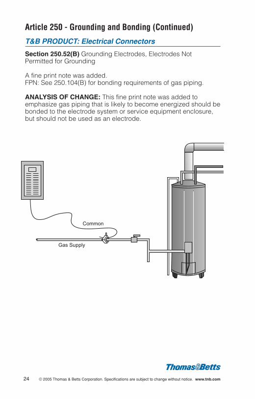
Section 250.52(B) Grounding Electrodes, Electrodes NotPermitted for Grounding
A fine print note was added.FPN: See 250.104(B) for bonding requirements of gas piping.
ANALYSIS OF CHANGE: This fine print note was added toemphasize gas piping that is likely to become energized should bebonded to the electrode system or service equipment enclosure,but should not be used as an electrode.
24 © 2005 Thomas & Betts Corporation. Specifications are subject to change without notice. www.tnb.com
Common
Gas Supply
© 2005 Thomas & Betts Corporation. Specifications are subject to change without notice. www.tnb.com 25
Article 250 - Grounding and Bonding (Continued)
T&B PRODUCT: Conduit Fittings
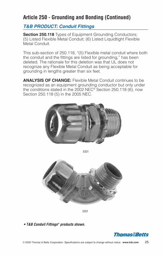
Section 250.118 Types of Equipment Grounding Conductors; (5) Listed Flexible Metal Conduit; (6) Listed Liquidtight FlexibleMetal Conduit.
This sub-section of 250.118, “(5) Flexible metal conduit where boththe conduit and the fittings are listed for grounding,” has beendeleted. The rationale for this deletion was that UL does notrecognize any Flexible Metal Conduit as being acceptable forgrounding in lengths greater than six feet.
ANALYSIS OF CHANGE: Flexible Metal Conduit continues to berecognized as an equipment grounding conductor but only underthe conditions stated in the 2002 NEC® Section 250.118 (6), nowSection 250.118 (5) in the 2005 NEC.
5331
5351
• T&B Conduit Fittings® products shown.

Article 250 - Grounding and Bonding (Continued)
T&B PRODUCT: Conduit Fittings, Terminals
Section 250.118 Types of Equipment Grounding Conductors; (5) Listed Flexible Metal Conduit; (6) Listed Liquidtight FlexibleMetal Conduit.
The statement, “where flexibility is necessary after installation” wasadded to both of these items in the types of equipment groundingconductors list. This identifies when an equipment groundingconductor (a green wire) must be added.
ANALYSIS OF CHANGE: There was confusion in previous coderequirements. Clarification was added by clearly stating that whenflexibility is needed after an installation, such as a motorinstallation, one cannot rely on the sheath of flexible metal conduitor liquidtight flexible metal conduit as the equipment groundingconductor. An equipment grounding conductor (a green wire),must be installed. Previous wording could have been interpretedas requiring the installation of an equipment grounding conductor(a green wire) when the conduit must be flexed to be installed.
5331
5351
• T&B Conduit Fittings® products shown.
26 © 2005 Thomas & Betts Corporation. Specifications are subject to change without notice. www.tnb.com
© 2005 Thomas & Betts Corporation. Specifications are subject to change without notice. www.tnb.com 27
Article 250 - Grounding and Bonding (Continued)
T&B PRODUCT: General
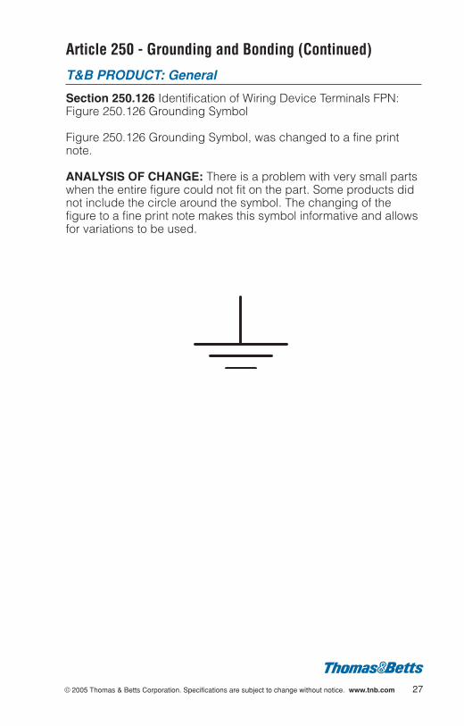
Section 250.126 Identification of Wiring Device Terminals FPN:Figure 250.126 Grounding Symbol
Figure 250.126 Grounding Symbol, was changed to a fine printnote.
ANALYSIS OF CHANGE: There is a problem with very small partswhen the entire figure could not fit on the part. Some products didnot include the circle around the symbol. The changing of thefigure to a fine print note makes this symbol informative and allowsfor variations to be used.

Article 250 - Grounding and Bonding (Continued)
T&B PRODUCT: Metallic Outlet Boxes
Section 250.146(A) Connecting Receptacle Grounding Terminal toBox; Surface Mounted Box
At least one of the insulating washers shall be removed fromreceptacles that do not have a contact yoke or device thatcomplies with 250.146(B) to ensure metal to metal contact.
ANALYSIS OF CHANGE: On surface mounted metal boxes, non-self grounding receptacles may be used without an equipmentbonding jumper, as long as one of the insulating washers isremoved. There was concern that these fiber washers would inhibita good grounding connection between the device and box.
28 © 2005 Thomas & Betts Corporation. Specifications are subject to change without notice. www.tnb.com

© 2005 Thomas & Betts Corporation. Specifications are subject to change without notice. www.tnb.com 29
Article 300 - Wiring Methods
T&B PRODUCT: CP-1 Cable Protector
Section 300.4(D) Protection Against Physical Damage; Cablesand Raceways Parallel to Framing Members or Furring Strips.
This change adds “or Furring Strips” to the section title and adds“or is installed parallel to furring strips” to the laundry list ofexposed and concealed locations where a cable or raceway-typewiring method is installed parallel to framing members. Also, adds“cable or raceway shall be installed and supported so that thenearest outside of the cable or raceway is not less than 32 mm (1b in.) from the nearest edge of the framing member or furringstrip where nails or screws are likely to penetrate. Where thisdistance cannot be maintained, the cable or raceway shall beprotected from penetration by nails or screws by a steel plate,sleeve or equivalent at least 1.6 mm (h in.) thick.”
ANALYSIS OF CHANGE: The proposal was written becausefurring strips are not normally considered framing members andprotection for the cable or raceway still needs to be maintained.This new requirement presents a new application for cableprotectors and the like.
• Steel City® products shown.

Article 300 - Wiring Methods (Continued)
T&B PRODUCT: CP-1 Cable Protector
Section 300.4(A)(1) Exception No. 2 (New) Protection AgainstPhysical Damage; Cable and Raceways Through Wood members;Bored Holes.
The existing Exception will be relabeled Exception No. 1, and thefollowing wording will be inserted as Exception No. 2. “A listed andmarked steel plate less than 1.6 mm (h in.) thick that providesequal or better protection against nail or screw penetration shall bepermitted”.
ANALYSIS OF CHANGE: The substantiation provided with theproposal indicated that the current h in. thick cable protectorswere being penetrated by self-tapping and drywall screws. Testscompared heat-treated spring steel protectors that were in the .020to .032 in. thickness range to the current h in. thick protectors andthe results were that neither of the screws was able to penetratethe heat treated spring steel and thus they provided equivalent orbetter protection for the cables.
CP-1
• Steel City® products shown.
30 © 2005 Thomas & Betts Corporation. Specifications are subject to change without notice. www.tnb.com
© 2005 Thomas & Betts Corporation. Specifications are subject to change without notice. www.tnb.com 31
Article 300 - Wiring Methods (Continued)
T&B PRODUCT: CP-1 Cable Protector
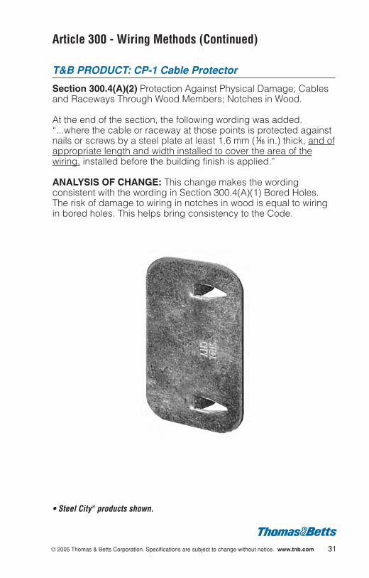
Section 300.4(A)(2) Protection Against Physical Damage; Cablesand Raceways Through Wood Members; Notches in Wood.
At the end of the section, the following wording was added.“...where the cable or raceway at those points is protected againstnails or screws by a steel plate at least 1.6 mm (h in.) thick, and ofappropriate length and width installed to cover the area of thewiring, installed before the building finish is applied.”
ANALYSIS OF CHANGE: This change makes the wordingconsistent with the wording in Section 300.4(A)(1) Bored Holes.The risk of damage to wiring in notches in wood is equal to wiringin bored holes. This helps bring consistency to the Code.
• Steel City® products shown.
Article 300 - Wiring Methods (Continued)
T&B PRODUCT: CP-1 Cable Protector
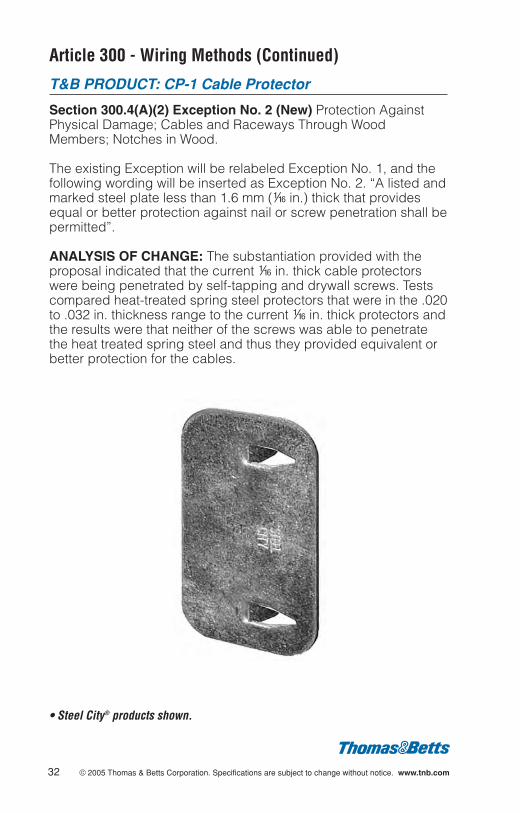
Section 300.4(A)(2) Exception No. 2 (New) Protection AgainstPhysical Damage; Cables and Raceways Through WoodMembers; Notches in Wood.
The existing Exception will be relabeled Exception No. 1, and thefollowing wording will be inserted as Exception No. 2. “A listed andmarked steel plate less than 1.6 mm (h in.) thick that providesequal or better protection against nail or screw penetration shall bepermitted”.
ANALYSIS OF CHANGE: The substantiation provided with theproposal indicated that the current h in. thick cable protectorswere being penetrated by self-tapping and drywall screws. Testscompared heat-treated spring steel protectors that were in the .020to .032 in. thickness range to the current h in. thick protectors andthe results were that neither of the screws was able to penetratethe heat treated spring steel and thus they provided equivalent orbetter protection for the cables.
32 © 2005 Thomas & Betts Corporation. Specifications are subject to change without notice. www.tnb.com
• Steel City® products shown.
© 2005 Thomas & Betts Corporation. Specifications are subject to change without notice. www.tnb.com 33
Article 300 - Wiring Methods (Continued)
T&B PRODUCT: CP-1 Cable Protector
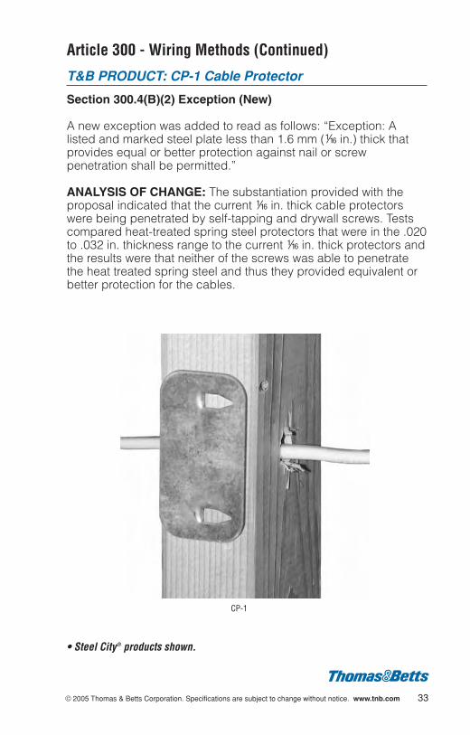
Section 300.4(B)(2) Exception (New)
A new exception was added to read as follows: “Exception: Alisted and marked steel plate less than 1.6 mm (h in.) thick thatprovides equal or better protection against nail or screwpenetration shall be permitted.”
ANALYSIS OF CHANGE: The substantiation provided with theproposal indicated that the current h in. thick cable protectorswere being penetrated by self-tapping and drywall screws. Testscompared heat-treated spring steel protectors that were in the .020to .032 in. thickness range to the current h in. thick protectors andthe results were that neither of the screws was able to penetratethe heat treated spring steel and thus they provided equivalent orbetter protection for the cables.
CP-1
• Steel City® products shown.

Article 300 - Wiring Methods (Continued)
T&B PRODUCT: CP-1 Cable Protector
Section 300.4(D) Exception No. 3 (New) Protection AgainstPhysical Damage; Cables and Raceways Parallel to FramingMembers.
A new exception was added to read as follows: “Exception No.3: A listed and marked steel plate less than 1.6 mm (h in.) thick thatprovides equal or better protection against nail or screwpenetration shall be permitted.”
ANALYSIS OF CHANGE: The substantiation provided with theproposal indicated that the current h in. thick cable protectorswere being penetrated by self-tapping and drywall screws. Testscompared heat-treated spring steel protectors that were in the .020to .032 in. thickness range to the current h in. thick protectors andthe results were that neither of the screws was able to penetratethe heat treated spring steel and thus they provided equivalent orbetter protection for the cables.
34 © 2005 Thomas & Betts Corporation. Specifications are subject to change without notice. www.tnb.com
• Steel City® products shown.
© 2005 Thomas & Betts Corporation. Specifications are subject to change without notice. www.tnb.com 35
Article 300 - Wiring Methods (Continued)
T&B PRODUCT: CP-1 Cable Protector
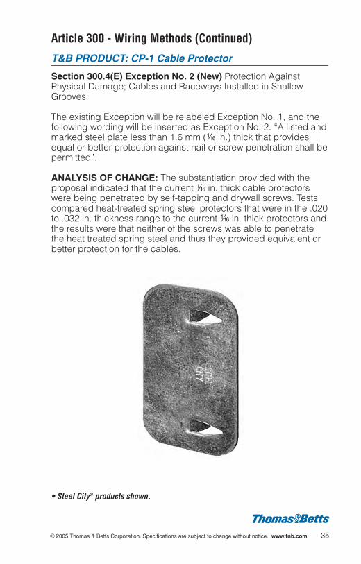
Section 300.4(E) Exception No. 2 (New) Protection AgainstPhysical Damage; Cables and Raceways Installed in ShallowGrooves.
The existing Exception will be relabeled Exception No. 1, and thefollowing wording will be inserted as Exception No. 2. “A listed andmarked steel plate less than 1.6 mm (h in.) thick that providesequal or better protection against nail or screw penetration shall bepermitted”.
ANALYSIS OF CHANGE: The substantiation provided with theproposal indicated that the current h in. thick cable protectorswere being penetrated by self-tapping and drywall screws. Testscompared heat-treated spring steel protectors that were in the .020to .032 in. thickness range to the current h in. thick protectors andthe results were that neither of the screws was able to penetratethe heat treated spring steel and thus they provided equivalent orbetter protection for the cables.
• Steel City® products shown.
Article 300 - Wiring Methods (Continued)
T&B PRODUCT: All
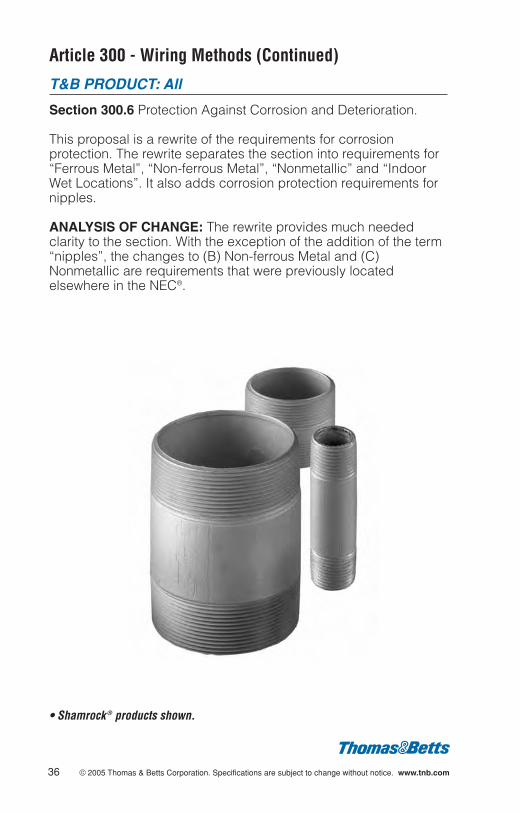
Section 300.6 Protection Against Corrosion and Deterioration.
This proposal is a rewrite of the requirements for corrosionprotection. The rewrite separates the section into requirements for“Ferrous Metal”, “Non-ferrous Metal”, “Nonmetallic” and “IndoorWet Locations”. It also adds corrosion protection requirements fornipples.
ANALYSIS OF CHANGE: The rewrite provides much neededclarity to the section. With the exception of the addition of the term“nipples”, the changes to (B) Non-ferrous Metal and (C)Nonmetallic are requirements that were previously locatedelsewhere in the NEC®.
36 © 2005 Thomas & Betts Corporation. Specifications are subject to change without notice. www.tnb.com
• Shamrock ® products shown.
© 2005 Thomas & Betts Corporation. Specifications are subject to change without notice. www.tnb.com 37
Article 300 - Wiring Methods (Continued)
T&B PRODUCT: Kopr-Shield ™
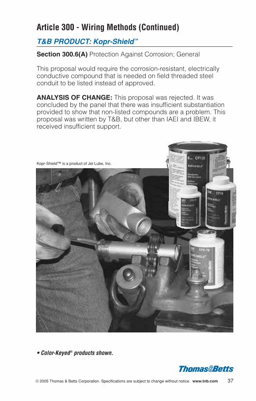
Section 300.6(A) Protection Against Corrosion; General
This proposal would require the corrosion-resistant, electricallyconductive compound that is needed on field threaded steelconduit to be listed instead of approved.
ANALYSIS OF CHANGE: This proposal was rejected. It wasconcluded by the panel that there was insufficient substantiationprovided to show that non-listed compounds are a problem. Thisproposal was written by T&B, but other than IAEI and IBEW, itreceived insufficient support.
• Color-Keyed® products shown.
Kopr-Shield™ is a product of Jet Lube, Inc.
Article 300 - Wiring Methods (Continued)
T&B PRODUCT: Raceways
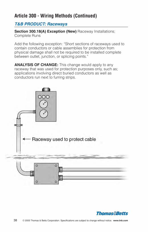
Section 300.18(A) Exception (New) Raceway Installations;Complete Runs
Add the following exception: “Short sections of raceways used tocontain conductors or cable assemblies for protection fromphysical damage shall not be required to be installed completebetween outlet, junction, or splicing points.”
ANALYSIS OF CHANGE: This change would apply to anyraceway that was used for protection purposes only, such as;applications involving direct buried conductors as well asconductors run next to furring strips.
38 © 2005 Thomas & Betts Corporation. Specifications are subject to change without notice. www.tnb.com

© 2005 Thomas & Betts Corporation. Specifications are subject to change without notice. www.tnb.com 39
Article 300 - Wiring Methods (Continued)
T&B PRODUCT: Liquidtight Flexible Metal Conduitand Fittings
Section 300.22(B) Wiring in Ducts, Plenums, and Other Air-Handling Spaces; Ducts or Plenums Used for Environmental Air
The term “Liquidtight Flexible Metal Conduit” was removed fromthe list of approved wiring methods permitted to be used in ductsor plenums specifically used to transport environmental air.
ANALYSIS OF CHANGE: In the last Code cycle, all PVC productswere removed from the list of acceptable products for use in ductsor plenums or other spaces used for environmental air. Thischange simply updates 300.22(B) to agree with the 2002 change.
Raceways with nonmetallic covering listed for use in such spaces
Air HandlingUnit Duct
Article 310 - Conductors for General Wiring
T&B PRODUCT : EMT and Rigid Conduit Fittings
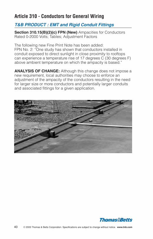
Section 310.15(B)(2)(c) FPN (New) Ampacities for ConductorsRated 0-2000 Volts; Tables; Adjustment Factors
The following new Fine Print Note has been added: FPN No. 2: “One study has shown that conductors installed inconduit exposed to direct sunlight in close proximity to rooftopscan experience a temperature rise of 17 degrees C (30 degrees F)above ambient temperature on which the ampacity is based.”
ANALYSIS OF CHANGE: Although this change does not impose anew requirement, local authorities may choose to enforce anadjustment of the ampacity of the conductors resulting in the needfor larger size or more conductors and potentially larger conduitsand associated fittings for a given application.
40 © 2005 Thomas & Betts Corporation. Specifications are subject to change without notice. www.tnb.com
© 2005 Thomas & Betts Corporation. Specifications are subject to change without notice. www.tnb.com 41
Article 312 - Cabinets, Cutout Boxes, and Meter SocketEnclosures
T&B PRODUCT: Fittings
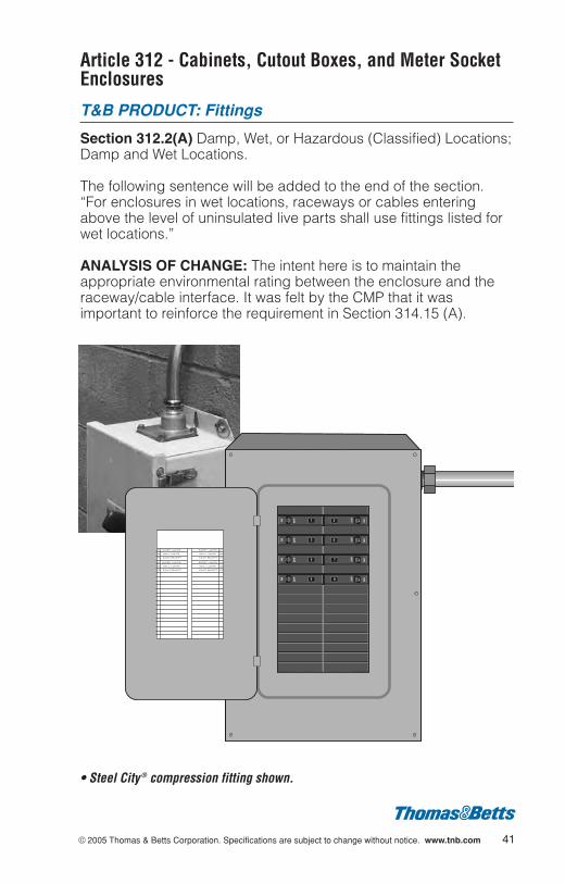
Section 312.2(A) Damp, Wet, or Hazardous (Classified) Locations;Damp and Wet Locations.
The following sentence will be added to the end of the section.“For enclosures in wet locations, raceways or cables enteringabove the level of uninsulated live parts shall use fittings listed forwet locations.”
ANALYSIS OF CHANGE: The intent here is to maintain theappropriate environmental rating between the enclosure and theraceway/cable interface. It was felt by the CMP that it wasimportant to reinforce the requirement in Section 314.15 (A).
• Steel City ® compression fitting shown.
Article 314 - Outlet, Device, Pull, and Junction Boxes;Conduit Bodies; Fittings; and Handhole Enclosures
T&B PRODUCT: Metallic and Nonmetallic Boxes
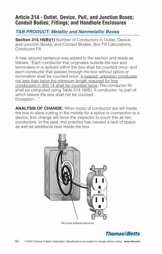
Section 314.16(B)(1) Number of Conductors in Outlet, Device,and Junction Boxes, and Conduit Bodies, Box Fill Calculations,Conductor Fill.
A new second sentence was added to the section and reads asfollows: “Each conductor that originates outside the box andterminates or is spliced within the box shall be counted once, andeach conductor that passes through the box without splice ortermination shall be counted once. A looped, unbroken conductornot less than twice the minimum length required for freeconductors in 300.14 shall be counted twice. The conductor fillshall be computed using Table 314.16(B). A conductor, no part ofwhich leaves the box shall not be counted.Exception:...”
ANALYSIS OF CHANGE: When loops of conductor are left insidethe box to allow cutting in the middle for a splice or connection to adevice, this change will force the inspector to count this as twoconductors. In the past, this practice has caused a lack of spaceas well as additional heat inside the box.
42 © 2005 Thomas & Betts Corporation. Specifications are subject to change without notice. www.tnb.com
Will require Additional Deductions
© 2005 Thomas & Betts Corporation. Specifications are subject to change without notice. www.tnb.com 43
Article 314 - Outlet, Device, Pull, and Junction Boxes;Conduit Bodies; Fittings; and Handhole Enclosures
T&B PRODUCT: Metallic and Nonmetallic Boxes
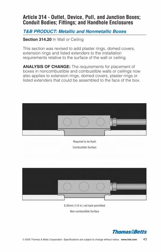
Section 314.20 In Wall or Ceiling
This section was revised to add plaster rings, domed covers,extension rings and listed extenders to the installationrequirements relative to the surface of the wall or ceiling.
ANALYSIS OF CHANGE: The requirements for placement ofboxes in noncombustible and combustible walls or ceilings nowalso applies to extension rings, domed covers, plaster rings orlisted extenders that could be assembled to the face of the box.
6.35mm (1/4 in.) set back permitted
Non-combustible Surface
Required to be flush
Combustible Surface
Article 314 - Outlet, Device, Pull, and Junction Boxes;Conduit Bodies; Fittings; and Handhole Enclosures(Continued)
T&B PRODUCT: Metallic and Nonmetallic Boxes
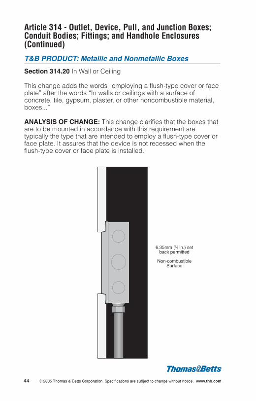
Section 314.20 In Wall or Ceiling
This change adds the words “employing a flush-type cover or faceplate” after the words “In walls or ceilings with a surface ofconcrete, tile, gypsum, plaster, or other noncombustible material,boxes...”
ANALYSIS OF CHANGE: This change clarifies that the boxes thatare to be mounted in accordance with this requirement aretypically the type that are intended to employ a flush-type cover orface plate. It assures that the device is not recessed when theflush-type cover or face plate is installed.
6.35mm (b in.) setback permitted
Non-combustibleSurface
44 © 2005 Thomas & Betts Corporation. Specifications are subject to change without notice. www.tnb.com
© 2005 Thomas & Betts Corporation. Specifications are subject to change without notice. www.tnb.com 45
Article 314 - Outlet, Device, Pull, and Junction Boxes;Conduit Bodies; Fittings; and Handhole Enclosures(Continued)
T&B PRODUCT: Metallic and Nonmetallic Boxes
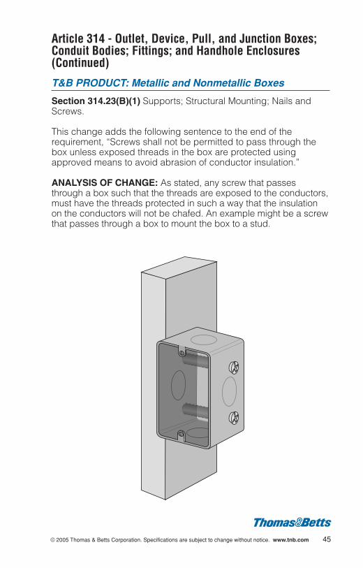
Section 314.23(B)(1) Supports; Structural Mounting; Nails andScrews.
This change adds the following sentence to the end of therequirement, “Screws shall not be permitted to pass through thebox unless exposed threads in the box are protected usingapproved means to avoid abrasion of conductor insulation.”
ANALYSIS OF CHANGE: As stated, any screw that passesthrough a box such that the threads are exposed to the conductors,must have the threads protected in such a way that the insulationon the conductors will not be chafed. An example might be a screwthat passes through a box to mount the box to a stud.
Article 314 - Outlet, Device, Pull, and Junction Boxes;Conduit Bodies; Fittings; and Handhole Enclosures(Continued)
T&B PRODUCT: Metallic and Nonmetallic Ceiling Boxes
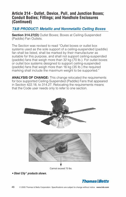
Section 314.27(D) Outlet Boxes; Boxes at Ceiling-Suspended(Paddle) Fan Outlets.
The Section was revised to read “Outlet boxes or outlet boxsystems used as the sole support of a ceiling-suspended (paddle)fan shall be listed, shall be marked by their manufacturer assuitable for this purpose, and shall not support ceiling-suspended(paddle) fans that weigh more than 32 kg (70 lb.). For outlet boxesor outlet box systems designed to support ceiling-suspended(paddle) fans that weigh more than 16 kg (35 lb.) the requiredmarking shall include the maximum weight to be supported.”
ANALYSIS OF CHANGE: This change relocated the requirementsfor box supported Ceiling-Suspended (Paddle) Fans that appearedin Section 422.18, to 314.27. Relocating the requirements meansthat the Code user needs only to refer to one section.
46 © 2005 Thomas & Betts Corporation. Specifications are subject to change without notice. www.tnb.com
Cannot exceed 70 lbs.
• Steel City ® products shown.

© 2005 Thomas & Betts Corporation. Specifications are subject to change without notice. www.tnb.com 47
Article 314 - Outlet, Device, Pull, and Junction Boxes;Conduit Bodies; Fittings; and Handhole Enclosures(Continued)
T&B PRODUCT: Boxes and Conduit Bodies
Section 314.29 Boxes, Conduit Bodies, and Handhole Enclosuresto Be Accessible.
“Handhole Enclosures” was added to the section so it reads,“Boxes, conduit bodies, and handhole enclosures shall beinstalled so that the wiring contained in them can be renderedaccessible without removing any part of the building or, inunderground circuits, without excavating sidewalks, paving, earth,or other substance that is to be used to establish the finishedgrade.
Exception: Listed boxes and handhole enclosures shall bepermitted where covered by gravel, light aggregate, or non-cohesive soil if their location is effectively identified and accessiblefor excavation.
ANALYSIS OF CHANGE: The requirement was expanded toinclude handhole enclosures. New Section 314.30 was establishedto cover the requirements for handhole enclosures. This term anddefinition was also added to Article 100.
Article 342 - Intermediate Metal Conduit: Type IMC
T&B PRODUCT: Conduit, Elbows, and Conduit Benders
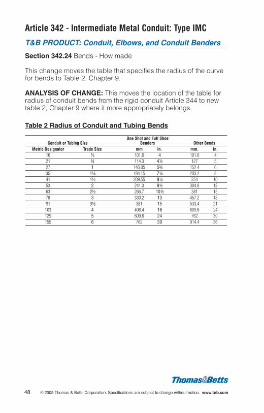
Section 342.24 Bends - How made
This change moves the table that specifies the radius of the curvefor bends to Table 2, Chapter 9.
ANALYSIS OF CHANGE: This moves the location of the table forradius of conduit bends from the rigid conduit Article 344 to newtable 2, Chapter 9 where it more appropriately belongs.
Table 2 Radius of Conduit and Tubing Bends
One Shot and Full ShoeConduit or Tubing Size Benders Other Bends
Metric Designator Trade Size mm in. mm. in.16 d 101.6 4 101.6 421 f 114.3 4d 127 527 1 146.05 5f 152.4 635 1b 184.15 7b 203.2 841 1d 209.55 8b 254 1053 2 241.3 9d 304.8 1263 2d 266.7 10d 381 1578 3 330.2 13 457.2 1891 3d 381 15 533.4 21103 4 406.4 16 609.6 24129 5 609.6 24 762 30155 6 762 30 914.4 36
48 © 2005 Thomas & Betts Corporation. Specifications are subject to change without notice. www.tnb.com
© 2005 Thomas & Betts Corporation. Specifications are subject to change without notice. www.tnb.com 49
Article 342 - Intermediate Metal Conduit: Type IMC(Continued)
T&B PRODUCT: Conduit, Elbows and Fittings
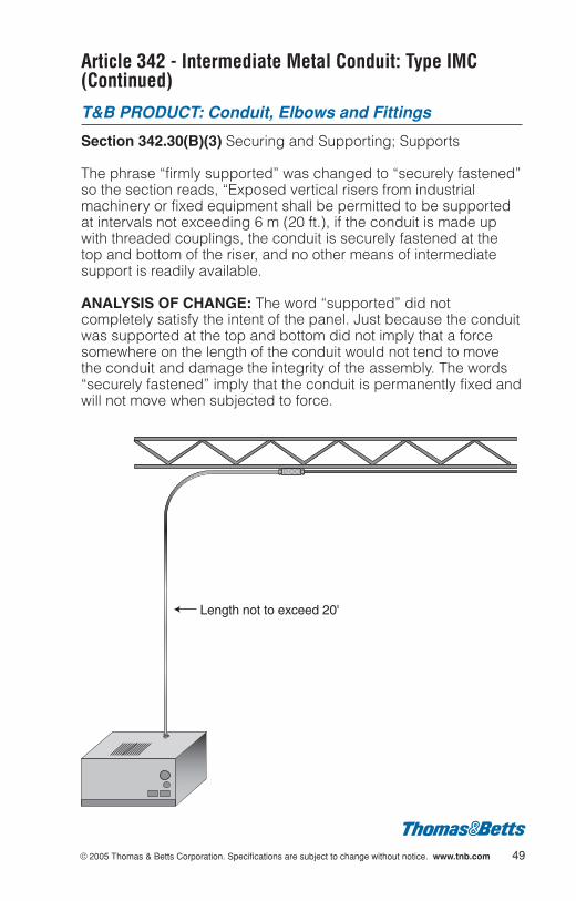
Section 342.30(B)(3) Securing and Supporting; Supports
The phrase “firmly supported” was changed to “securely fastened”so the section reads, “Exposed vertical risers from industrialmachinery or fixed equipment shall be permitted to be supportedat intervals not exceeding 6 m (20 ft.), if the conduit is made upwith threaded couplings, the conduit is securely fastened at thetop and bottom of the riser, and no other means of intermediatesupport is readily available.
ANALYSIS OF CHANGE: The word “supported” did notcompletely satisfy the intent of the panel. Just because the conduitwas supported at the top and bottom did not imply that a forcesomewhere on the length of the conduit would not tend to movethe conduit and damage the integrity of the assembly. The words“securely fastened” imply that the conduit is permanently fixed andwill not move when subjected to force.
Length not to exceed 20'
Article 342 - Intermediate Metal Conduit: Type IMC(Continued)
T&B PRODUCT: Conduit, Elbows and Fittings
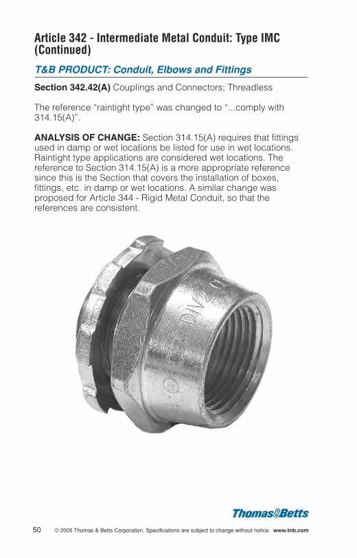
Section 342.42(A) Couplings and Connectors; Threadless
The reference “raintight type” was changed to “...comply with314.15(A)”.
ANALYSIS OF CHANGE: Section 314.15(A) requires that fittingsused in damp or wet locations be listed for use in wet locations.Raintight type applications are considered wet locations. Thereference to Section 314.15(A) is a more appropriate referencesince this is the Section that covers the installation of boxes,fittings, etc. in damp or wet locations. A similar change wasproposed for Article 344 - Rigid Metal Conduit, so that thereferences are consistent.
50 © 2005 Thomas & Betts Corporation. Specifications are subject to change without notice. www.tnb.com
© 2005 Thomas & Betts Corporation. Specifications are subject to change without notice. www.tnb.com 51
Article 344 - Rigid Metal Conduit: Type RMC
T&B PRODUCT: Conduit, Elbows, Fittings and ConduitBenders
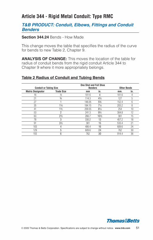
Section 344.24 Bends - How Made
This change moves the table that specifies the radius of the curvefor bends to new Table 2, Chapter 9.
ANALYSIS OF CHANGE: This moves the location of the table forradius of conduit bends from the rigid conduit Article 344 toChapter 9 where it more appropriately belongs.
Table 2 Radius of Conduit and Tubing Bends
One Shot and Full ShoeConduit or Tubing Size Benders Other Bends
Metric Designator Trade Size mm in. mm. in.16 d 101.6 4 101.6 421 f 114.3 4d 127 527 1 146.05 5f 152.4 635 1b 184.15 7b 203.2 841 1d 209.55 8b 254 1053 2 241.3 9d 304.8 1263 2d 266.7 10d 381 1578 3 330.2 13 457.2 1891 3d 381 15 533.4 21103 4 406.4 16 609.6 24129 5 609.6 24 762 30155 6 762 30 914.4 36

Article 344 - Rigid Metal Conduit: Type RMC (Continued)
T&B PRODUCT: Conduit, Elbows and Fittings
Section 344.30(B)(3) Securing and Supporting; Supports
The phrase “firmly supported” was changed to “securely fastened”so the section reads, “Exposed vertical risers from industrialmachinery or fixed equipment shall be permitted to be supportedat intervals not exceeding 6 m (20 ft.), if the conduit is made upwith threaded couplings, the conduit is securely fastened at thetop and bottom of the riser, and no other means of intermediatesupport is readily available.”
ANALYSIS OF CHANGE: The word “supported” did notcompletely satisfy the intent of the panel. Just because the conduitwas supported at the top and bottom did not imply that a forcesomewhere on the length of the conduit would not tend to movethe conduit and damage the integrity of the assembly. The words“securely fastened” imply that the conduit is permanently fixed andwill not move when subjected to force.
52 © 2005 Thomas & Betts Corporation. Specifications are subject to change without notice. www.tnb.com
Length not to exceed 20'

© 2005 Thomas & Betts Corporation. Specifications are subject to change without notice. www.tnb.com 53
Article 344 - Rigid Metal Conduit: Type RMC (Continued)
T&B PRODUCT: Conduit, Elbows and Fittings
Section 344.42(A) Couplings and Connectors; Threadless
The reference “raintight type” was changed to “....comply with314.15(A)”.
ANALYSIS OF CHANGE: Section 314.15(A) requires that fittingsused in damp or wet locations be listed for use in wet locations.Raintight type applications are considered wet locations. Thereference to Section 314.15(A) is a more appropriate referencesince this is the Section that covers the installation of boxes,fittings, etc. in damp or wet locations. A similar change wasproposed for Article 342 - Intermediate Metal Conduit, so that thereferences are consistent.

Article 348 - Flexible Metal Conduit: Type FMC
T&B PRODUCT: Fittings
Section 348.24 Bends - How Made
This change moves the table that specifies the radius of the curvefor bends to new Table 2, Chapter 9.
ANALYSIS OF CHANGE: This moves the location of the table forradius of conduit bends from the rigid conduit Article 344 toChapter 9 where it more appropriately belongs.
Table 2 Radius of Conduit and Tubing Bends
One Shot and Full ShoeConduit or Tubing Size Benders Other Bends
Metric Designator Trade Size mm in. mm. in.16 d 101.6 4 101.6 421 f 114.3 4d 127 527 1 146.05 5f 152.4 635 1b 184.15 7b 203.2 841 1d 209.55 8b 254 1053 2 241.3 9d 304.8 1263 2d 266.7 10d 381 1578 3 330.2 13 457.2 1891 3d 381 15 533.4 21103 4 406.4 16 609.6 24129 5 609.6 24 762 30155 6 762 30 914.4 36
54 © 2005 Thomas & Betts Corporation. Specifications are subject to change without notice. www.tnb.com

© 2005 Thomas & Betts Corporation. Specifications are subject to change without notice. www.tnb.com 55
Up to 3' (3/4'')
Article 348 - Flexible Metal Conduit: Type FMC(Continued)
T&B PRODUCT: Fittings
Section 348.30(A) Securing and Supporting; Securely Fastened;Exception No. 2
The exception that eliminates the need for support of flexible metalconduit installed where flexibility was required, was expanded forthe larger trade sizes of conduit. Previously the unsupportedlength for all trade sizes was the same, 900 mm (3 ft.). The newexception reads:
Exception No. 2: At terminals where flexibility is required, lengthsshall not exceed:
(1) 900 mm (3 ft.) for metric designators 16 through 35 (tradesizes d through 1b)
(2) 1200 mm (4 ft.) for metric designators 41 through 53 (tradesizes 1d through 2)
(3) 1500 mm (5 ft.) for metric designators 63 (trade size 2d) andlarger.
ANALYSIS OF CHANGE: The change will provide neededflexibility to the installer when connecting conduit to motor junctionboxes. The longer length will also allow for easier replacement ofV-belts and improve ease of maintenance.
Article 348 - Flexible Metal Conduit: Type FMC(Continued)
T&B PRODUCT: Fittings
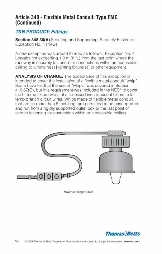
Section 348.30(A) Securing and Supporting; Securely Fastened;Exception No. 4 (New)
A new exception was added to read as follows: Exception No. 4:Lengths not exceeding 1.8 m (6 ft.) from the last point where theraceway is securely fastened for connections within an accessibleceiling to luminaire(s) [lighting fixture(s)] or other equipment.
ANALYSIS OF CHANGE: The acceptance of this exception isintended to cover the installation of a flexible metal conduit “whip”.Some have felt that the use of “whips” was covered in Section410.67(C), but this requirement was included in the NEC® to coverthe hi-temp fixture wires of a recessed incandescent fixture to lo-temp branch circuit wires. Whips made of flexible metal conduitthat are no more than 6 feet long, are permitted to be unsupportedand run from a rigidly supported outlet box or the last point ofsecure fastening for connection within an accessible ceiling.
Maximum length 6 feet
56 © 2005 Thomas & Betts Corporation. Specifications are subject to change without notice. www.tnb.com
© 2005 Thomas & Betts Corporation. Specifications are subject to change without notice. www.tnb.com 57
Article 348 - Flexible Metal Conduit: Type FMC(Continued)
T&B PRODUCT: Fittings
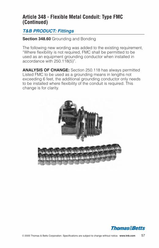
Section 348.60 Grounding and Bonding
The following new wording was added to the existing requirement,“Where flexibility is not required, FMC shall be permitted to beused as an equipment grounding conductor when installed inaccordance with 250.118(5)”.
ANALYSIS OF CHANGE: Section 250.118 has always permittedListed FMC to be used as a grounding means in lengths notexceeding 6 feet, the additional grounding conductor only needsto be installed where flexibility of the conduit is required. Thischange is for clarity.
Article 350 - Liquidtight Flexible Metal Conduit: TypeLFMC
T&B PRODUCT: Liquidtight Flexible Metal Conduit and Fittings
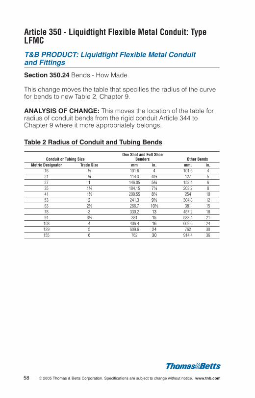
Section 350.24 Bends - How Made
This change moves the table that specifies the radius of the curvefor bends to new Table 2, Chapter 9.
ANALYSIS OF CHANGE: This moves the location of the table forradius of conduit bends from the rigid conduit Article 344 toChapter 9 where it more appropriately belongs.
Table 2 Radius of Conduit and Tubing Bends
One Shot and Full ShoeConduit or Tubing Size Benders Other Bends
Metric Designator Trade Size mm in. mm. in.16 d 101.6 4 101.6 421 f 114.3 4d 127 527 1 146.05 5f 152.4 635 1b 184.15 7b 203.2 841 1d 209.55 8b 254 1053 2 241.3 9d 304.8 1263 2d 266.7 10d 381 1578 3 330.2 13 457.2 1891 3d 381 15 533.4 21103 4 406.4 16 609.6 24129 5 609.6 24 762 30155 6 762 30 914.4 36
58 © 2005 Thomas & Betts Corporation. Specifications are subject to change without notice. www.tnb.com
© 2005 Thomas & Betts Corporation. Specifications are subject to change without notice. www.tnb.com 59
Article 350 - Liquidtight Flexible Metal Conduit(Continued)
T&B PRODUCT: Liquidtight Flexible Metal Conduit and Fittings
Section 350.30(A) Securing and Supporting; Securely Fastened
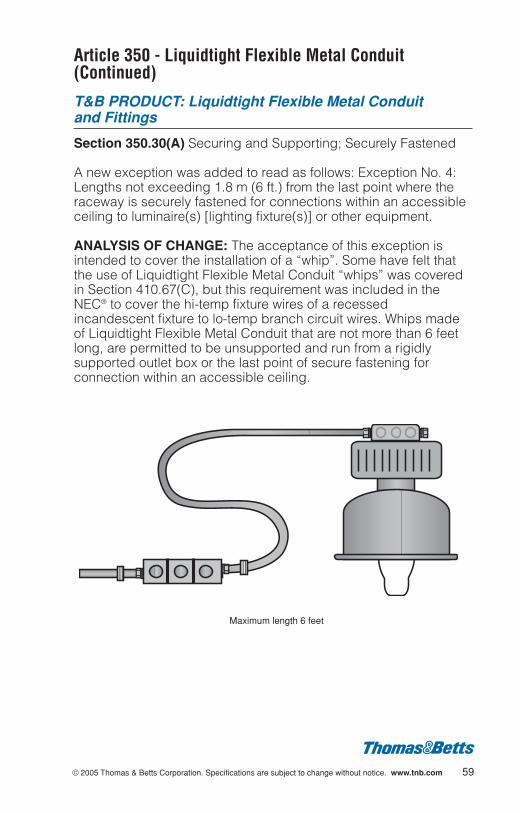
A new exception was added to read as follows: Exception No. 4:Lengths not exceeding 1.8 m (6 ft.) from the last point where theraceway is securely fastened for connections within an accessibleceiling to luminaire(s) [lighting fixture(s)] or other equipment.
ANALYSIS OF CHANGE: The acceptance of this exception isintended to cover the installation of a “whip”. Some have felt thatthe use of Liquidtight Flexible Metal Conduit “whips” was coveredin Section 410.67(C), but this requirement was included in theNEC® to cover the hi-temp fixture wires of a recessedincandescent fixture to lo-temp branch circuit wires. Whips madeof Liquidtight Flexible Metal Conduit that are not more than 6 feetlong, are permitted to be unsupported and run from a rigidlysupported outlet box or the last point of secure fastening forconnection within an accessible ceiling.
Maximum length 6 feet
Article 350 - Liquidtight Flexible Metal Conduit: TypeLFMC (Continued)
T&B PRODUCT: Liquidtight Flexible Metal Conduit and Fittings
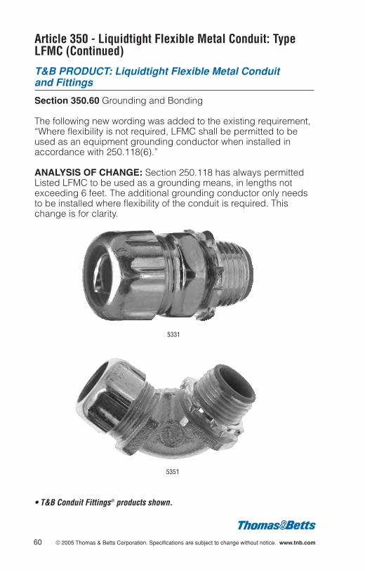
Section 350.60 Grounding and Bonding
The following new wording was added to the existing requirement,“Where flexibility is not required, LFMC shall be permitted to beused as an equipment grounding conductor when installed inaccordance with 250.118(6).”
ANALYSIS OF CHANGE: Section 250.118 has always permittedListed LFMC to be used as a grounding means, in lengths notexceeding 6 feet. The additional grounding conductor only needsto be installed where flexibility of the conduit is required. Thischange is for clarity.
5331
5351
• T&B Conduit Fittings® products shown.
60 © 2005 Thomas & Betts Corporation. Specifications are subject to change without notice. www.tnb.com
© 2005 Thomas & Betts Corporation. Specifications are subject to change without notice. www.tnb.com 61
Article 352 - Rigid Nonmetallic Conduit: Type RNC(Continued)
T&B PRODUCT: Fittings
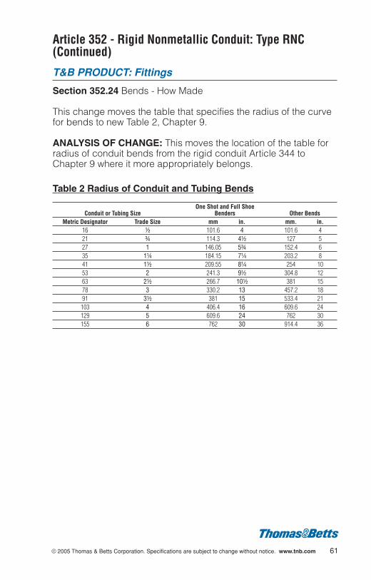
Section 352.24 Bends - How Made
This change moves the table that specifies the radius of the curvefor bends to new Table 2, Chapter 9.
ANALYSIS OF CHANGE: This moves the location of the table forradius of conduit bends from the rigid conduit Article 344 toChapter 9 where it more appropriately belongs.
Table 2 Radius of Conduit and Tubing Bends
One Shot and Full ShoeConduit or Tubing Size Benders Other Bends
Metric Designator Trade Size mm in. mm. in.16 d 101.6 4 101.6 421 f 114.3 4d 127 527 1 146.05 5f 152.4 635 1b 184.15 7b 203.2 841 1d 209.55 8b 254 1053 2 241.3 9d 304.8 1263 2d 266.7 10d 381 1578 3 330.2 13 457.2 1891 3d 381 15 533.4 21103 4 406.4 16 609.6 24129 5 609.6 24 762 30155 6 762 30 914.4 36

Article 353 - High Density Polyethylene Conduit: Type HDPE Conduit
T&B PRODUCT: Information only
New Article
This new Article was written so that HDPE requirements could beextracted from Article 352 Rigid Nonmetallic Conduit.
ANALYSIS OF CHANGE: HDPE Conduit is currently a listedproduct that is restricted in its uses and is sometimes substitutedas a Rigid Nonmetallic Conduit and used underground. There arehowever, differences between HDPE and RNC in that the thermalexpansion characteristics are different as well as some differencesin the Uses Permitted and Uses Not Permitted sections.
62 © 2005 Thomas & Betts Corporation. Specifications are subject to change without notice. www.tnb.com
© 2005 Thomas & Betts Corporation. Specifications are subject to change without notice. www.tnb.com 63
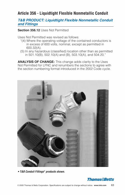
Article 356 - Liquidtight Flexible Nonmetallic Conduit
T&B PRODUCT: Liquidtight Flexible Nonmetallic Conduitand Fittings
Section 356.12 Uses Not Permitted
Uses Not Permitted was revised as follows:“(4) Where the operating voltage of the contained conductors is
in excess of 600 volts, nominal, except as permitted in600.32(A).
(5) In any hazardous (classified) location other than as permittedin 501.10(B), 502.10(A) and (B), 503.10(A), and 504.20.”
ANALYSIS OF CHANGE: This change adds clarity to the UsesNot Permitted for LFNC and renumbers the sections to agree withthe section numbering format introduced in the 2002 Code cycle.
• T&B Conduit Fittings® products shown.
Article 356 - Liquidtight Flexible Nonmetallic Conduit:Type LFNC (Continued)
T&B PRODUCT: Liquidtight Flexible Nonmetallic Conduitand Fittings
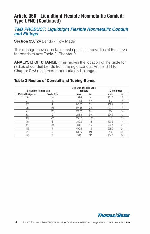
Section 356.24 Bends - How Made
This change moves the table that specifies the radius of the curvefor bends to new Table 2, Chapter 9.
ANALYSIS OF CHANGE: This moves the location of the table forradius of conduit bends from the rigid conduit Article 344 toChapter 9 where it more appropriately belongs.
Table 2 Radius of Conduit and Tubing Bends
One Shot and Full ShoeConduit or Tubing Size Benders Other Bends
Metric Designator Trade Size mm in. mm. in.16 d 101.6 4 101.6 421 f 114.3 4d 127 527 1 146.05 5f 152.4 635 1b 184.15 7b 203.2 841 1d 209.55 8b 254 1053 2 241.3 9d 304.8 1263 2d 266.7 10d 381 1578 3 330.2 13 457.2 1891 3d 381 15 533.4 21103 4 406.4 16 609.6 24129 5 609.6 24 762 30155 6 762 30 914.4 36
64 © 2005 Thomas & Betts Corporation. Specifications are subject to change without notice. www.tnb.com
© 2005 Thomas & Betts Corporation. Specifications are subject to change without notice. www.tnb.com 65
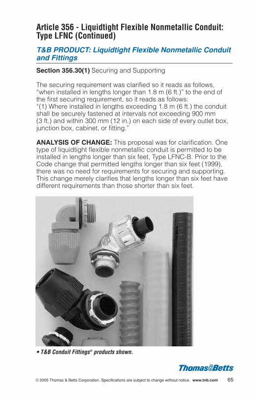
Article 356 - Liquidtight Flexible Nonmetallic Conduit:Type LFNC (Continued)
T&B PRODUCT: Liquidtight Flexible Nonmetallic Conduitand Fittings
Section 356.30(1) Securing and Supporting
The securing requirement was clarified so it reads as follows,“when installed in lengths longer than 1.8 m (6 ft.)” to the end ofthe first securing requirement, so it reads as follows:“(1) Where installed in lengths exceeding 1.8 m (6 ft.) the conduitshall be securely fastened at intervals not exceeding 900 mm (3 ft.) and within 300 mm (12 in.) on each side of every outlet box,junction box, cabinet, or fitting.”
ANALYSIS OF CHANGE: This proposal was for clarification. Onetype of liquidtight flexible nonmetallic conduit is permitted to beinstalled in lengths longer than six feet, Type LFNC-B. Prior to theCode change that permitted lengths longer than six feet (1999),there was no need for requirements for securing and supporting.This change merely clarifies that lengths longer than six feet havedifferent requirements than those shorter than six feet.
• T&B Conduit Fittings® products shown.
Article 356 - Liquidtight Flexible Nonmetallic Conduit:Type LFNC (Continued)
T&B PRODUCT: Liquidtight Flexible Nonmetallic Conduitand Fittings
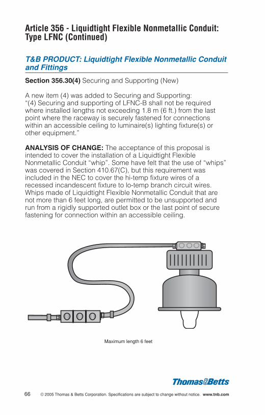
Section 356.30(4) Securing and Supporting (New)
A new item (4) was added to Securing and Supporting:“(4) Securing and supporting of LFNC-B shall not be requiredwhere installed lengths not exceeding 1.8 m (6 ft.) from the lastpoint where the raceway is securely fastened for connectionswithin an accessible ceiling to luminaire(s) lighting fixture(s) orother equipment.”
ANALYSIS OF CHANGE: The acceptance of this proposal isintended to cover the installation of a Liquidtight FlexibleNonmetallic Conduit “whip”. Some have felt that the use of “whips”was covered in Section 410.67(C), but this requirement wasincluded in the NEC to cover the hi-temp fixture wires of arecessed incandescent fixture to lo-temp branch circuit wires.Whips made of Liquidtight Flexible Nonmetallic Conduit that arenot more than 6 feet long, are permitted to be unsupported andrun from a rigidly supported outlet box or the last point of securefastening for connection within an accessible ceiling.
66 © 2005 Thomas & Betts Corporation. Specifications are subject to change without notice. www.tnb.com
Maximum length 6 feet

© 2005 Thomas & Betts Corporation. Specifications are subject to change without notice. www.tnb.com 67
Article 356 - Liquidtight Flexible Nonmetallic Conduit:Type LFNC (Continued)
T&B PRODUCT: Liquidtight Flexible Nonmetallic Conduitand Fittings
Section 356.42 Couplings and Connectors
The Section was revised as follows:“356.42 Connectors and Couplings. Only fittings listed for use withLFNC shall be used. Angle connectors shall not be used forconcealed raceway installations.”
ANALYSIS OF CHANGE: This change requires that fittings usedwith LFNC to be listed for that application since there have beensome instances where fittings have been solvent cemented ontoLFNC.
• T&B Conduit Fittings® products shown.
Article 356 - Liquidtight Flexible Nonmetallic Conduit:Type LFNC (Continued)
T&B PRODUCT: Liquidtight Flexible Nonmetallic Conduitand Fittings
Section 356.42 Couplings and Connectors
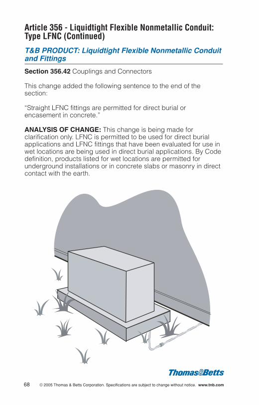
This change added the following sentence to the end of thesection:
“Straight LFNC fittings are permitted for direct burial orencasement in concrete.”
ANALYSIS OF CHANGE: This change is being made forclarification only. LFNC is permitted to be used for direct burialapplications and LFNC fittings that have been evaluated for use inwet locations are being used in direct burial applications. By Codedefinition, products listed for wet locations are permitted forunderground installations or in concrete slabs or masonry in directcontact with the earth.
68 © 2005 Thomas & Betts Corporation. Specifications are subject to change without notice. www.tnb.com
© 2005 Thomas & Betts Corporation. Specifications are subject to change without notice. www.tnb.com 69
Article 358 - Electrical Metallic Tubing: Type EMT
T&B PRODUCT: EMT, Elbows and EMT Benders
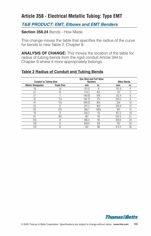
Section 358.24 Bends - How Made
This change moves the table that specifies the radius of the curvefor bends to new Table 2, Chapter 9.
ANALYSIS OF CHANGE: This moves the location of the table forradius of tubing bends from the rigid conduit Article 344 toChapter 9 where it more appropriately belongs.
Table 2 Radius of Conduit and Tubing Bends
One Shot and Full ShoeConduit or Tubing Size Benders Other Bends
Metric Designator Trade Size mm in. mm. in.16 d 101.6 4 101.6 421 f 114.3 4d 127 527 1 146.05 5f 152.4 635 1b 184.15 7b 203.2 841 1d 209.55 8b 254 1053 2 241.3 9d 304.8 1263 2d 266.7 10d 381 1578 3 330.2 13 457.2 1891 3d 381 15 533.4 21103 4 406.4 16 609.6 24129 5 609.6 24 762 30155 6 762 30 914.4 36

Article 358 Electrical Metallic Tubing: Type EMT(Continued)
T&B PRODUCT: Fittings
Section 358.42 Connectors and Couplings
The reference “raintight type” was changed to “...comply with314.15(A)”.
ANALYSIS OF CHANGE: Section 314.15(A) requires that fittingsused in damp or wet locations be listed for use in wet locations.Raintight type applications are considered wet locations. Thereference to Section 314.15(A) is a more appropriate referencesince this is the section that covers the installation of boxes,fittings, etc. in damp or wet locations.
70 © 2005 Thomas & Betts Corporation. Specifications are subject to change without notice. www.tnb.com
© 2005 Thomas & Betts Corporation. Specifications are subject to change without notice. www.tnb.com 71
Article 362 - Electrical Nonmetallic Tubing: Type ENT
T&B PRODUCT: Information only
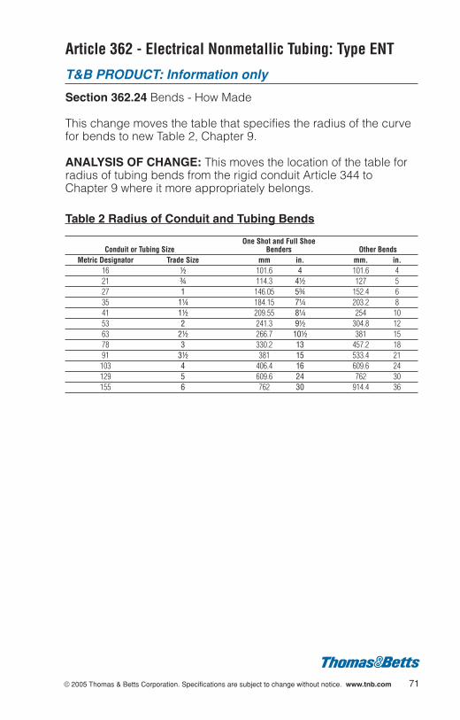
Section 362.24 Bends - How Made
This change moves the table that specifies the radius of the curvefor bends to new Table 2, Chapter 9.
ANALYSIS OF CHANGE: This moves the location of the table forradius of tubing bends from the rigid conduit Article 344 toChapter 9 where it more appropriately belongs.
Table 2 Radius of Conduit and Tubing Bends
One Shot and Full ShoeConduit or Tubing Size Benders Other Bends
Metric Designator Trade Size mm in. mm. in.16 d 101.6 4 101.6 421 f 114.3 4d 127 527 1 146.05 5f 152.4 635 1b 184.15 7b 203.2 841 1d 209.55 8b 254 1053 2 241.3 9d 304.8 1263 2d 266.7 10d 381 1578 3 330.2 13 457.2 1891 3d 381 15 533.4 21103 4 406.4 16 609.6 24129 5 609.6 24 762 30155 6 762 30 914.4 36
Article 362 - Electrical Nonmetallic Tubing: Type ENT(Continued)
T&B PRODUCT: Information only
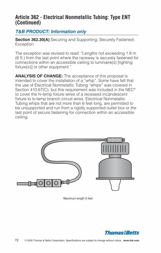
Section 362.30(A) Securing and Supporting; Securely Fastened;Exception
The exception was revised to read: “Lengths not exceeding 1.8 m(6 ft.) from the last point where the raceway is securely fastened forconnections within an accessible ceiling to luminaire(s) [lightingfixture(s)] or other equipment.”
ANALYSIS OF CHANGE: The acceptance of this proposal isintended to cover the installation of a “whip”. Some have felt thatthe use of Electrical Nonmetallic Tubing “whips” was covered inSection 410.67(C), but this requirement was included in the NEC®
to cover the hi-temp fixture wires of a recessed incandescentfixture to lo-temp branch circuit wires. Electrical NonmetallicTubing whips that are not more than 6 feet long, are permitted tobe unsupported and run from a rigidly supported outlet box or thelast point of secure fastening for connection within an accessibleceiling.
72 © 2005 Thomas & Betts Corporation. Specifications are subject to change without notice. www.tnb.com
Maximum length 6 feet
© 2005 Thomas & Betts Corporation. Specifications are subject to change without notice. www.tnb.com 73
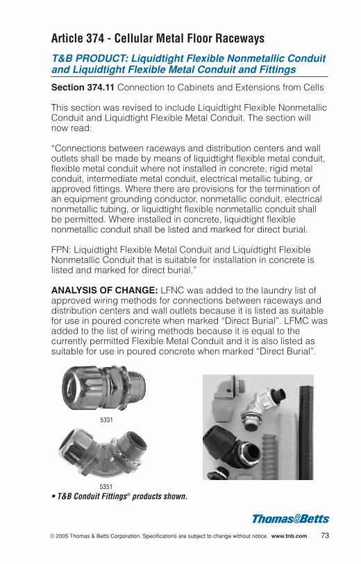
Article 374 - Cellular Metal Floor Raceways
T&B PRODUCT: Liquidtight Flexible Nonmetallic Conduitand Liquidtight Flexible Metal Conduit and Fittings
Section 374.11 Connection to Cabinets and Extensions from Cells
This section was revised to include Liquidtight Flexible NonmetallicConduit and Liquidtight Flexible Metal Conduit. The section willnow read:
“Connections between raceways and distribution centers and walloutlets shall be made by means of liquidtight flexible metal conduit,flexible metal conduit where not installed in concrete, rigid metalconduit, intermediate metal conduit, electrical metallic tubing, orapproved fittings. Where there are provisions for the termination ofan equipment grounding conductor, nonmetallic conduit, electricalnonmetallic tubing, or liquidtight flexible nonmetallic conduit shallbe permitted. Where installed in concrete, liquidtight flexiblenonmetallic conduit shall be listed and marked for direct burial.
FPN: Liquidtight Flexible Metal Conduit and Liquidtight FlexibleNonmetallic Conduit that is suitable for installation in concrete islisted and marked for direct burial.”
ANALYSIS OF CHANGE: LFNC was added to the laundry list ofapproved wiring methods for connections between raceways anddistribution centers and wall outlets because it is listed as suitablefor use in poured concrete when marked “Direct Burial”. LFMC wasadded to the list of wiring methods because it is equal to thecurrently permitted Flexible Metal Conduit and it is also listed assuitable for use in poured concrete when marked “Direct Burial”.
5331
5351
• T&B Conduit Fittings® products shown.
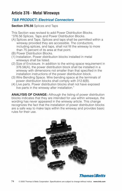
Article 376 - Metal Wireways
T&B PRODUCT: Electrical Connectors
Section 376.56 Splices and Taps
This Section was revised to add Power Distribution Blocks.“376.56 Splices, Taps and Power Distribution Blocks.(A) Splices and Taps. Splices and taps shall be permitted within a
wireway provided they are accessible. The conductors,including splices, and taps, shall not fill the wireway to morethan 75 percent of its area at that point.
(B) Power Distribution Blocks. (1) Installation. Power distribution blocks installed in metal
wireways shall be listed.(2) Size of Enclosure. In addition to the wiring space requirement in
376.56(A), the power distribution block shall be installed in awireway with dimensions not smaller than that specified in theinstallation instructions of the power distribution block.
(3) Wire Bending Space. Wire bending space at the terminals ofpower distribution blocks shall comply with 312.6(B).
(4) Live parts. Power distribution blocks shall not have exposedlive parts in the wireway after installation.”
ANALYSIS OF CHANGE: Although the listing of power distributionblocks indicates that they are intended for use within wireways, thewording has never appeared in the wireway article. This changerecognizes the fact that the installation of power distribution blocksare a safe way to make taps within the wireway and provides basicrules for their use.
74 © 2005 Thomas & Betts Corporation. Specifications are subject to change without notice. www.tnb.com
© 2005 Thomas & Betts Corporation. Specifications are subject to change without notice. www.tnb.com 75
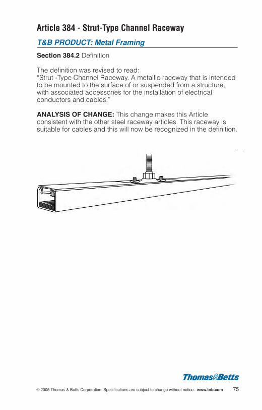
Article 384 - Strut-Type Channel Raceway
T&B PRODUCT: Metal Framing
Section 384.2 Definition
The definition was revised to read:“Strut -Type Channel Raceway. A metallic raceway that is intendedto be mounted to the surface of or suspended from a structure,with associated accessories for the installation of electricalconductors and cables.”
ANALYSIS OF CHANGE: This change makes this Articleconsistent with the other steel raceway articles. This raceway issuitable for cables and this will now be recognized in the definition.
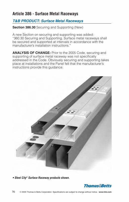
Article 386 - Surface Metal Raceways
T&B PRODUCT: Surface Metal Raceways
Section 386.30 Securing and Supporting (New)
A new Section on securing and supporting was added:“360.30 Securing and Supporting. Surface metal raceways shallbe secured and supported at intervals in accordance with themanufacturer’s installation instructions.”
ANALYSIS OF CHANGE: Prior to the 2005 Code, securing andsupporting of surface metal raceway was not specificallyaddressed in the Code. Obviously securing and supporting takesplace at installations and the Panel felt that the manufacturer’sinstructions provide this guidance.
• Steel City® Surface Raceway products shown.
76 © 2005 Thomas & Betts Corporation. Specifications are subject to change without notice. www.tnb.com
© 2005 Thomas & Betts Corporation. Specifications are subject to change without notice. www.tnb.com 77
Article 386 - Surface Metal Raceways (Continued)
T&B PRODUCT: Surface Metal Raceway
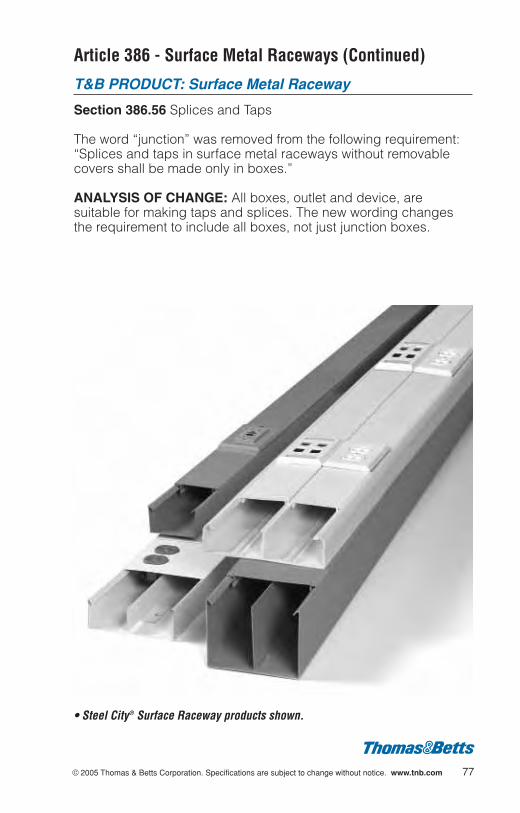
Section 386.56 Splices and Taps
The word “junction” was removed from the following requirement:“Splices and taps in surface metal raceways without removablecovers shall be made only in boxes.”
ANALYSIS OF CHANGE: All boxes, outlet and device, aresuitable for making taps and splices. The new wording changesthe requirement to include all boxes, not just junction boxes.
• Steel City® Surface Raceway products shown.
Article 386 - Surface Metal Raceways (Continued)
T&B PRODUCT: Surface Metal Raceways
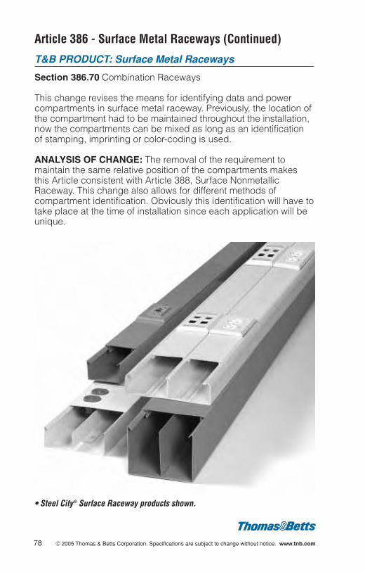
Section 386.70 Combination Raceways
This change revises the means for identifying data and powercompartments in surface metal raceway. Previously, the location ofthe compartment had to be maintained throughout the installation,now the compartments can be mixed as long as an identificationof stamping, imprinting or color-coding is used.
ANALYSIS OF CHANGE: The removal of the requirement tomaintain the same relative position of the compartments makesthis Article consistent with Article 388, Surface NonmetallicRaceway. This change also allows for different methods ofcompartment identification. Obviously this identification will have totake place at the time of installation since each application will beunique.
• Steel City® Surface Raceway products shown.
78 © 2005 Thomas & Betts Corporation. Specifications are subject to change without notice. www.tnb.com

© 2005 Thomas & Betts Corporation. Specifications are subject to change without notice. www.tnb.com 79
Article 388 - Surface Nonmetallic Raceways
T&B PRODUCT: Surface Nonmetallic Raceways
Section 388.56 Splices and Taps
The word “junction” was removed from the following requirement:“Splices and taps in surface nonmetallic raceways withoutremovable covers shall be made only in boxes.
ANALYSIS OF CHANGE: All boxes, outlet and device, aresuitable for making taps and splices. The new wording changesthe requirement to include all boxes, not just junction boxes.
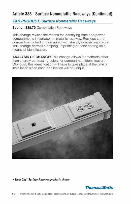
Article 388 - Surface Nonmetallic Raceways (Continued)
T&B PRODUCT: Surface Nonmetallic Raceways
Section 388.70 Combination Raceways
This change revises the means for identifying data and powercompartments in surface nonmetallic raceway. Previously, thecompartments had to be marked with sharply contrasting colors.This change permits stamping, imprinting or color-coding as ameans of identification.
ANALYSIS OF CHANGE: This change allows for methods otherthan sharply contrasting colors for compartment identification.Obviously this identification will have to take place at the time ofinstallation since each application will be unique.
• Steel City® Surface Raceway products shown.
80 © 2005 Thomas & Betts Corporation. Specifications are subject to change without notice. www.tnb.com
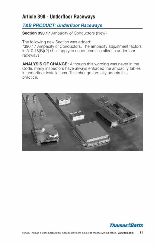
© 2005 Thomas & Betts Corporation. Specifications are subject to change without notice. www.tnb.com 81
Article 390 - Underfloor Raceways
T&B PRODUCT: Underfloor Raceways
Section 390.17 Ampacity of Conductors (New)
The following new Section was added:“390.17 Ampacity of Conductors. The ampacity adjustment factorsin 310.15(B)(2) shall apply to conductors installed in underfloorraceways.”
ANALYSIS OF CHANGE: Although this wording was never in theCode, many inspectors have always enforced the ampacity tablesin underfloor installations. This change formally adopts thispractice.
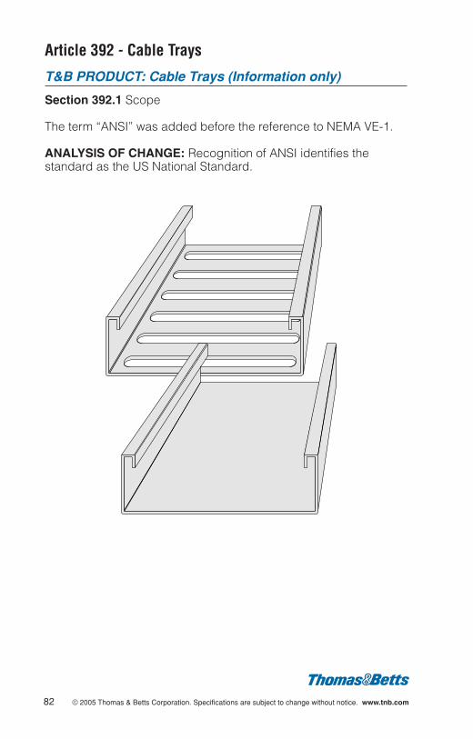
Article 392 - Cable Trays
T&B PRODUCT: Cable Trays (Information only)
Section 392.1 Scope
The term “ANSI” was added before the reference to NEMA VE-1.
ANALYSIS OF CHANGE: Recognition of ANSI identifies thestandard as the US National Standard.
82 © 2005 Thomas & Betts Corporation. Specifications are subject to change without notice. www.tnb.com

© 2005 Thomas & Betts Corporation. Specifications are subject to change without notice. www.tnb.com 83
Article 392 - Cable Trays (Continued)
T&B PRODUCT: Cable Trays
Section 392.4 Uses Not Permitted
The term “environmental airspaces” was changed to “ducts,plenums, and other air-handling spaces”.
ANALYSIS OF CHANGE: This change is being made forconsistency, since proposals have been made to change otherArticles in the NEC®.
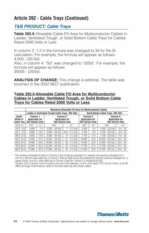
Article 392 - Cable Trays (Continued)
T&B PRODUCT: Cable Trays
Table 392.9 Allowable Cable Fill Area for Multiconductor Cables inLadder, Ventilated Trough, or Solid Bottom Cable Trays for CablesRated 2000 Volts or Less
In column 2, 1.2 in the formula was changed to 30 for the SIcalculation. For example, the formula will appear as follows:4,500 - (30 Sd)Also, in column 4, “Sd” was changed to “25Sd”. For example, theformula will appear as follows:35005 - (25Sd).
ANALYSIS OF CHANGE: This change is editorial. The table wasincorrect in the 2002 NEC® publication.
Table 392.9 Allowable Cable Fill Area for MulticonductorCables in Ladder, Ventilated Trough, or Solid Bottom CableTrays for Cables Rated 2000 Volts or Less
Maximum Allowable Fill Area for Multiconductor CablesLadder or Ventilated Trough Cable Trays, 392.9(A) Solid Bottom Cable Trays, 392.9(C)
Inside Column 1 Column 2a Column 3 Column 4a
Width of Applicable for Applicable for Applicable for Applicable forCable Tray 392.9(A)(2) Only 392.9(A)(3) Only 392.9(C)(2) Only 392.9(C)(3) Only
mm in. mm2 in.2 mm2 in.2 mm2 in.2 mm2 in.2
150 6.0 4,500 7.0 4,500 - (30 Sd)b 7 - (1.2 Sd)b 3,500 5.5 3,500 - (25 Sd)b 5.5 - Sd225 9.0 6,800 10.5 6,800 - (30 Sd) 10.5 - (1.2 Sd) 5,100 8.0 5,100 - (25 Sd) 8.0 - Sd300 12.0 9,000 14.0 9,000 - (30 Sd) 14 - (1.2 Sd) 7,100 11.0 7,100 - (25 Sd) 11.0 - Sd450 18.0 13,500 21.0 13,500 - (30 Sd) 21 - (1.2 Sd) 10,600 16.5 10,600 - (25 Sd) 16.5 - Sd600 24.0 18,000 28.0 18,000 - (30 Sd) 28 - (1.2 Sd) 14,200 22.0 14,200 - (25 Sd) 22.0 - Sd750 30.0 22,500 35.0 22,500 - (30 Sd) 35 - (1.2 Sd) 17,700 27.5 17,700 - (25 Sd) 27.5 - Sd900 36.0 27,000 42.0 27,000 - (30 Sd) 42 - (1.2 Sd) 21,300 33.0 21,300 - (25 Sd) 33.0 - Sd
a The maximum allowable fill areas in Columns 2 and 4 shall be computed. For example, the maximum allowable fill inmm2 for a 150-mm wide cable tray in Column 2 shall be 4500 minus (30 multiplied by Sd) [the maximum allowable fill, insquare inches, for a 6-in. wide cable tray in Column 2 shall be 7 minus (1.2 multiplied by Sd)].
b The term Sd in Columns 2 and 4 is equal to the sum of the diameters, in mm, of all cables 107.2 mm (in inches, of all 4/0AWG) and larger multiconductor cables in the same cable tray with smaller cables.
84 © 2005 Thomas & Betts Corporation. Specifications are subject to change without notice. www.tnb.com
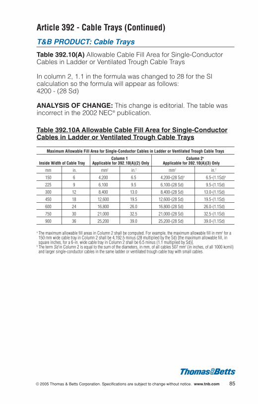
© 2005 Thomas & Betts Corporation. Specifications are subject to change without notice. www.tnb.com 85
Article 392 - Cable Trays (Continued)
T&B PRODUCT: Cable Trays
Table 392.10(A) Allowable Cable Fill Area for Single-ConductorCables in Ladder or Ventilated Trough Cable Trays
In column 2, 1.1 in the formula was changed to 28 for the SIcalculation so the formula will appear as follows:4200 - (28 Sd)
ANALYSIS OF CHANGE: This change is editorial. The table wasincorrect in the 2002 NEC® publication.
Table 392.10A Allowable Cable Fill Area for Single-ConductorCables in Ladder or Ventilated Trough Cable Trays
Maximum Allowable Fill Area for Single-Conductor Cables in Ladder or Ventilated Trough Cable Trays
Column 1 Column 2a
Inside Width of Cable Tray Applicable for 392.10(A)(2) Only Applicable for 392.10(A)(3) Only
mm in. mm2 in.2 mm2 in.2
150 6 4,200 6.5 4,200-(28 Sd)b 6.5-(1.1Sd)b
225 9 6,100 9.5 6,100-(28 Sd) 9.5-(1.1Sd)
300 12 8,400 13.0 8,400-(28 Sd) 13.0-(1.1Sd)
450 18 12,600 19.5 12,600-(28 Sd) 19.5-(1.1Sd)
600 24 16,800 26.0 16,800-(28 Sd) 26.0-(1.1Sd)
750 30 21,000 32.5 21,000-(28 Sd) 32.5-(1.1Sd)
900 36 25,200 39.0 25,200-(28 Sd) 39.0-(1.1Sd)
a The maximum allowable fill areas in Column 2 shall be computed. For example, the maximum allowable fill in mm2 for a150 mm wide cable tray in Column 2 shall be 4,192.5 minus (28 multiplied by the Sd) [the maximum allowable fill, insquare inches, for a 6-in. wide cable tray in Column 2 shall be 6.5 minus (1.1 multiplied by Sd)].
b The term Sd in Column 2 is equal to the sum of the diameters, in mm, of all cables 507 mm2 (in inches, of all 1000 kcmil)and larger single-conductor cables in the same ladder or ventilated trough cable tray with small cables.
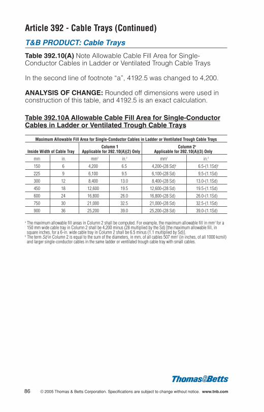
Article 392 - Cable Trays (Continued)
T&B PRODUCT: Cable Trays
Table 392.10(A) Note Allowable Cable Fill Area for Single-Conductor Cables in Ladder or Ventilated Trough Cable Trays
In the second line of footnote “a”, 4192.5 was changed to 4,200.
ANALYSIS OF CHANGE: Rounded off dimensions were used inconstruction of this table, and 4192.5 is an exact calculation.
Table 392.10A Allowable Cable Fill Area for Single-ConductorCables in Ladder or Ventilated Trough Cable Trays
Maximum Allowable Fill Area for Single-Conductor Cables in Ladder or Ventilated Trough Cable Trays
Column 1 Column 2a
Inside Width of Cable Tray Applicable for 392.10(A)(2) Only Applicable for 392.10(A)(3) Only
mm in. mm2 in.2 mm2 in.2
150 6 4,200 6.5 4,200-(28 Sd)b 6.5-(1.1Sd)b
225 9 6,100 9.5 6,100-(28 Sd) 9.5-(1.1Sd)
300 12 8,400 13.0 8,400-(28 Sd) 13.0-(1.1Sd)
450 18 12,600 19.5 12,600-(28 Sd) 19.5-(1.1Sd)
600 24 16,800 26.0 16,800-(28 Sd) 26.0-(1.1Sd)
750 30 21,000 32.5 21,000-(28 Sd) 32.5-(1.1Sd)
900 36 25,200 39.0 25,200-(28 Sd) 39.0-(1.1Sd)
a The maximum allowable fill areas in Column 2 shall be computed. For example, the maximum allowable fill in mm2 for a150 mm wide cable tray in Column 2 shall be 4,200 minus (28 multiplied by the Sd) [the maximum allowable fill, insquare inches, for a 6-in. wide cable tray in Column 2 shall be 6.5 minus (1.1 multiplied by Sd)].
b The term Sd in Column 2 is equal to the sum of the diameters, in mm, of all cables 507 mm2 (in inches, of all 1000 kcmil)and larger single-conductor cables in the same ladder or ventilated trough cable tray with small cables.
86 © 2005 Thomas & Betts Corporation. Specifications are subject to change without notice. www.tnb.com
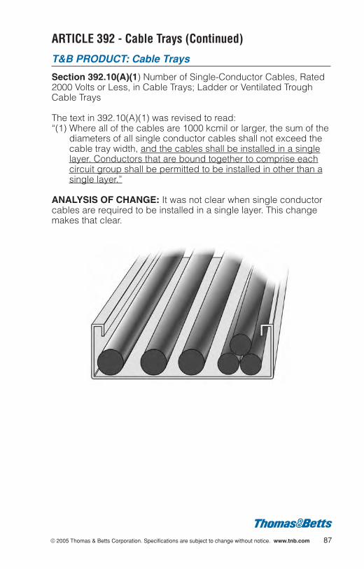
© 2005 Thomas & Betts Corporation. Specifications are subject to change without notice. www.tnb.com 87
ARTICLE 392 - Cable Trays (Continued)
T&B PRODUCT: Cable Trays
Section 392.10(A)(1) Number of Single-Conductor Cables, Rated2000 Volts or Less, in Cable Trays; Ladder or Ventilated TroughCable Trays
The text in 392.10(A)(1) was revised to read:“(1) Where all of the cables are 1000 kcmil or larger, the sum of the
diameters of all single conductor cables shall not exceed thecable tray width, and the cables shall be installed in a singlelayer. Conductors that are bound together to comprise eachcircuit group shall be permitted to be installed in other than asingle layer.”
ANALYSIS OF CHANGE: It was not clear when single conductorcables are required to be installed in a single layer. This changemakes that clear.
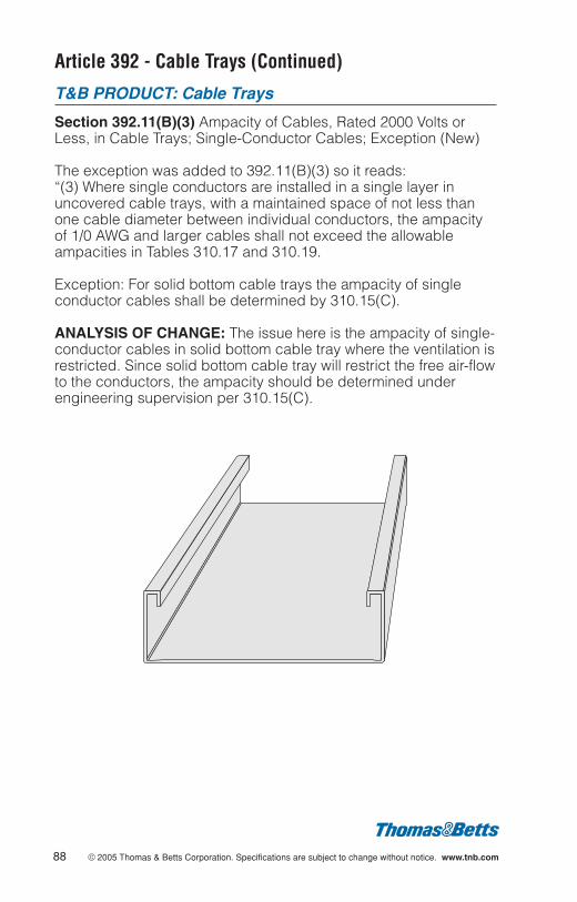
Article 392 - Cable Trays (Continued)
T&B PRODUCT: Cable Trays
Section 392.11(B)(3) Ampacity of Cables, Rated 2000 Volts orLess, in Cable Trays; Single-Conductor Cables; Exception (New)
The exception was added to 392.11(B)(3) so it reads:“(3) Where single conductors are installed in a single layer inuncovered cable trays, with a maintained space of not less thanone cable diameter between individual conductors, the ampacityof 1/0 AWG and larger cables shall not exceed the allowableampacities in Tables 310.17 and 310.19.
Exception: For solid bottom cable trays the ampacity of singleconductor cables shall be determined by 310.15(C).
ANALYSIS OF CHANGE: The issue here is the ampacity of single-conductor cables in solid bottom cable tray where the ventilation isrestricted. Since solid bottom cable tray will restrict the free air-flowto the conductors, the ampacity should be determined underengineering supervision per 310.15(C).
88 © 2005 Thomas & Betts Corporation. Specifications are subject to change without notice. www.tnb.com

© 2005 Thomas & Betts Corporation. Specifications are subject to change without notice. www.tnb.com 89
Article 404 - Switches
T&B PRODUCT: Steel device boxes
Section 404.10(B) Mounting of Snap Switches; Box Mounted
Section 404.10(B) was revised to replace references to “wallsurface” with “finished surface” as follows:
“(B) Box Mounted. Flush-type snap switches that are mounted inboxes that are set back of the finished surface as permitted in314.20 shall be installed so that the extension plaster ears areseated against the surface. Flush-type snap switches that aremounted in boxes that are flush with the finished surface or projectfrom it shall be installed so that the mounting yoke or strap of theswitch is seated against the box.
ANALYSIS OF CHANGE: This section was revised so that the ruleapplies to walls, ceilings, cabinets and any other type surfaces.
Article 406 - Receptacles, Cord Connectors andAttachment Plugs (Caps)
T&B PRODUCT: Flush Device Coverplates
Section 406.4 (D) Position of Receptacle FacesSection 406.4 (D) was revised by adding two exceptions:
Exception No. 1: Listed kits or assemblies encompassingreceptacles and nonmetallic faceplates that cover the receptacleface, where the plate cannot be installed on any other receptacle,shall be permitted.
Exception No.2: Listed nonmetallic faceplates that cover thereceptacle face to maximum thickness of 1 mm (0.040 in.) shall bepermitted.
ANALYSIS OF CHANGE: These new exceptions permitinstallation of specially designed coverplates that may not allowattachment plugs to attach flush with a receptacle face. ExceptionNo.1 permits kits containing specially designed receptacles andcoverplates to be installed. Exception No. 2 provides guidance forproduct standards (UL 514D) and permits up to 1 mm (0.040 in.)of nonmetallic material of a coverplate to come between anattachment plug and the face of the receptacle in which it isinstalled. The original proposal was substantiated on the basis thatthe 2002 Code language had resulted in de-listing of coverplateswith more than 10 years of use and having popular and effectivechild safety features.
NEMA manufacturers were strongly against Exception No. 2 citingsafety concerns wherever a gap is permitted between anattachment plug and the face of a receptacle.
90 © 2005 Thomas & Betts Corporation. Specifications are subject to change without notice. www.tnb.com
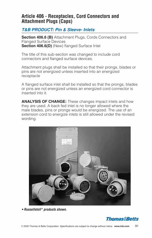
© 2005 Thomas & Betts Corporation. Specifications are subject to change without notice. www.tnb.com 91
Article 406 - Receptacles, Cord Connectors andAttachment Plugs (Caps)
T&B PRODUCT: Pin & Sleeve- Inlets
Section 406.6 (B) Attachment Plugs, Cords Connectors andFlanged Surface DevicesSection 406.6(D) (New) flanged Surface Inlet
The title of this sub-section was changed to include cordconnectors and flanged surface devices.
Attachment plugs shall be installed so that their prongs, blades orpins are not energized unless inserted into an energizedreceptacle
A flanged surface inlet shall be installed so that the prongs, bladesor pins are not energized unless an energized cord connector isinserted into it.
ANALYSIS OF CHANGE: These changes impact inlets and howthey are used. A back fed inlet is no longer allowed where themale blades, pins or prongs would be energized. The use of anextension cord to energize inlets is still allowed under the revisedwording.
• Russellstoll ® products shown.
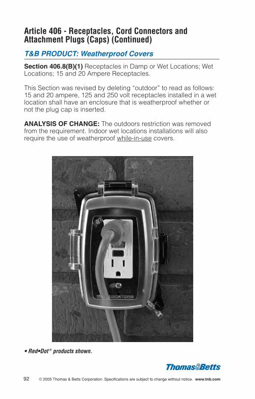
Article 406 - Receptacles, Cord Connectors andAttachment Plugs (Caps) (Continued)
T&B PRODUCT: Weatherproof Covers
Section 406.8(B)(1) Receptacles in Damp or Wet Locations; WetLocations; 15 and 20 Ampere Receptacles.
This Section was revised by deleting “outdoor” to read as follows:15 and 20 ampere, 125 and 250 volt receptacles installed in a wetlocation shall have an enclosure that is weatherproof whether ornot the plug cap is inserted.
ANALYSIS OF CHANGE: The outdoors restriction was removedfrom the requirement. Indoor wet locations installations will alsorequire the use of weatherproof while-in-use covers.
• Red•Dot ® products shown.
92 © 2005 Thomas & Betts Corporation. Specifications are subject to change without notice. www.tnb.com

© 2005 Thomas & Betts Corporation. Specifications are subject to change without notice. www.tnb.com 93
Article 406 - Receptacles, Cord Connectors andAttachment Plugs (Caps) (Continued)
T&B PRODUCT: All equipment
Section 406.9(B)(4) and Figure Grounding-Type Receptacles,Adapters, Cord Connectors, and Attachment Plugs; GroundingPole Identification
The grounding symbol was revised to a fine print note meaningthis specific symbol is not mandatory.
ANALYSIS OF CHANGE: There are many small products in theelectrical industry that can not accommodate the groundingsymbol inside the circle. This change allows manufacturers to usethe symbol without the circle.
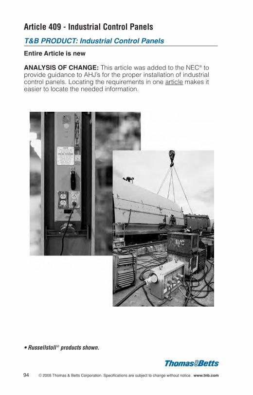
Article 409 - Industrial Control Panels
T&B PRODUCT: Industrial Control Panels
Entire Article is new
ANALYSIS OF CHANGE: This article was added to the NEC® toprovide guidance to AHJ’s for the proper installation of industrialcontrol panels. Locating the requirements in one article makes iteasier to locate the needed information.
94 © 2005 Thomas & Betts Corporation. Specifications are subject to change without notice. www.tnb.com
• Russellstoll ® products shown.

© 2005 Thomas & Betts Corporation. Specifications are subject to change without notice. www.tnb.com 95
Article 410 - Luminaires (Lighting Fixtures),Lampholders, and Lamps
T&B PRODUCT: Outlet Boxes, Lighting
Section 410.16A Means of Support; Outlet Boxes.
This Section was revised to read as follows: “(A) Outlet boxes orfittings installed as required by 314.23 and complying with theprovisions of 314.27(A) and 314.27(B) shall be permitted tosupport luminaires (fixtures).”
ANALYSIS OF CHANGE: There is no technical change to therequirements, simply a clarification of the rules on installation ofluminaires and how outlet boxes can be used as the means ofsupport for the luminaire. This was necessary due to the relocationof requirements from Section 410.16 to 314.27.
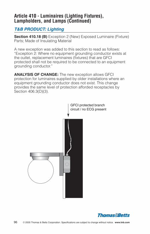
Article 410 - Luminaires (Lighting Fixtures),Lampholders, and Lamps (Continued)
T&B PRODUCT: Lighting
Section 410.18 (B) Exception 2 (New) Exposed Luminaire (Fixture)Parts; Made of Insulating Material
A new exception was added to this section to read as follows:“Exception 2: Where no equipment grounding conductor exists atthe outlet, replacement luminaires (fixtures) that are GFCIprotected shall not be required to be connected to an equipmentgrounding conductor.”
ANALYSIS OF CHANGE: The new exception allows GFCIprotection for luminaires supplied by older installations where anequipment grounding conductor does not exist. This changeprovides the same level of protection afforded receptacles bySection 406.3(D)(3).
96 © 2005 Thomas & Betts Corporation. Specifications are subject to change without notice. www.tnb.com
GFCI protected branch circuit / no ECG present

© 2005 Thomas & Betts Corporation. Specifications are subject to change without notice. www.tnb.com 97
Article 422 - Appliances
T&B PRODUCT: Ceiling Fan Boxes
Section 422.18 Support of Ceiling-Suspended (Paddle) Fans
The text for the support of ceiling-suspended paddle fans wasrevised by replacing the existing requirements for paddle fansweighing less than 35 lbs. and requirements for paddle fansweighing more than 35 lbs. with the following wording:
“Ceiling-Suspended (Paddle) Fans shall be supportedindependently of an outlet box or by listed outlet box or outletbox systems identified for the use and installed in accordancewith 314.27(D).”
ANALYSIS OF CHANGE: This change eliminates the need to referto two Code sections to determine what size Ceiling-Suspended(Paddle) Fans are permitted to be supported by an outlet box.There was a companion proposal written for Section 314.27(D)where the support requirements for boxes reside.
• Steel City ® products shown.
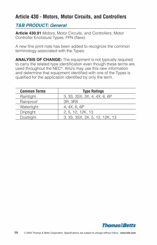
Article 430 - Motors, Motor Circuits, and Controllers
T&B PRODUCT: General
Article 430.91 Motors, Motor Circuits, and Controllers; MotorController Enclosure Types; FPN (New)
A new fine print note has been added to recognize the commonterminology associated with the Types.
ANALYSIS OF CHANGE: The equipment is not typically requiredto carry the related type identification even though these terms areused throughout the NEC®. AHJ’s may use this new informationand determine that equipment identified with one of the Types isqualified for the application identified by only the term.
Common Terms Type RatingsRaintight 3, 3S, 3SX, 3X, 4, 4X, 6, 6PRainproof 3R, 3RXWatertight 4, 4X, 6, 6PDriptight 2, 5, 12, 12K, 13Dusttight 3, 3S, 3SX, 3X, 5, 12, 12K, 13
98 © 2005 Thomas & Betts Corporation. Specifications are subject to change without notice. www.tnb.com
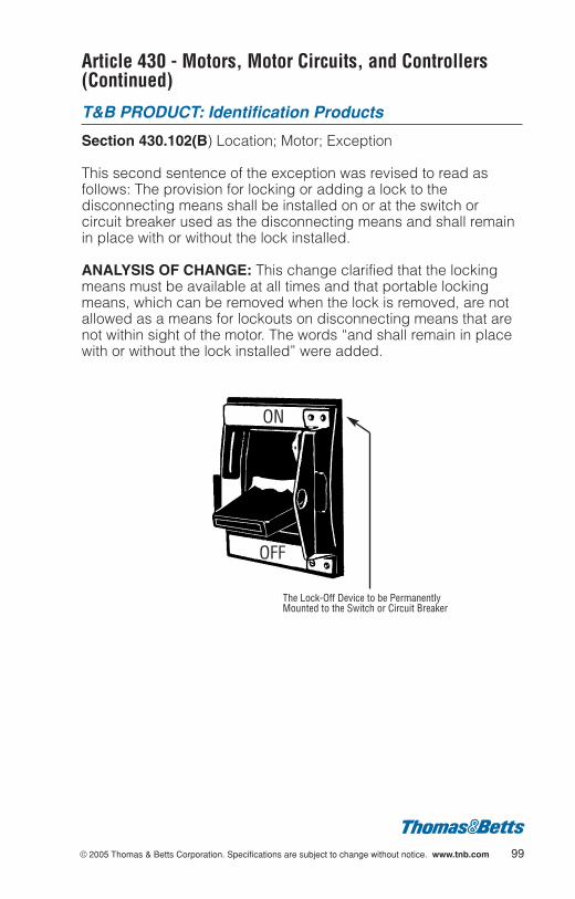
© 2005 Thomas & Betts Corporation. Specifications are subject to change without notice. www.tnb.com 99
Article 430 - Motors, Motor Circuits, and Controllers(Continued)
T&B PRODUCT: Identification Products
Section 430.102(B) Location; Motor; Exception
This second sentence of the exception was revised to read asfollows: The provision for locking or adding a lock to thedisconnecting means shall be installed on or at the switch orcircuit breaker used as the disconnecting means and shall remainin place with or without the lock installed.
ANALYSIS OF CHANGE: This change clarified that the lockingmeans must be available at all times and that portable lockingmeans, which can be removed when the lock is removed, are notallowed as a means for lockouts on disconnecting means that arenot within sight of the motor. The words “and shall remain in placewith or without the lock installed” were added.
ON
OFF
The Lock-Off Device to be PermanentlyMounted to the Switch or Circuit Breaker
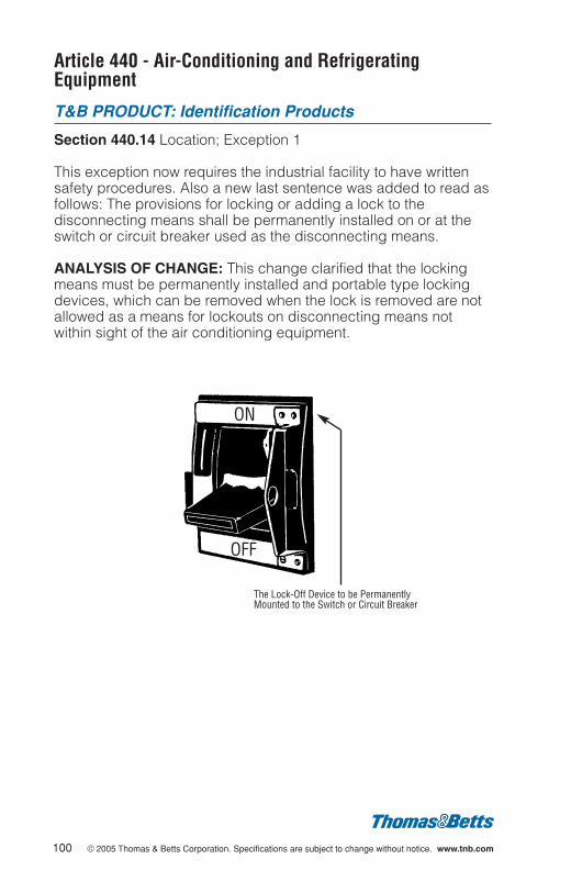
Article 440 - Air-Conditioning and RefrigeratingEquipment
T&B PRODUCT: Identification Products
Section 440.14 Location; Exception 1
This exception now requires the industrial facility to have writtensafety procedures. Also a new last sentence was added to read asfollows: The provisions for locking or adding a lock to thedisconnecting means shall be permanently installed on or at theswitch or circuit breaker used as the disconnecting means.
ANALYSIS OF CHANGE: This change clarified that the lockingmeans must be permanently installed and portable type lockingdevices, which can be removed when the lock is removed are notallowed as a means for lockouts on disconnecting means notwithin sight of the air conditioning equipment.
100 © 2005 Thomas & Betts Corporation. Specifications are subject to change without notice. www.tnb.com
ON
OFF
The Lock-Off Device to be PermanentlyMounted to the Switch or Circuit Breaker
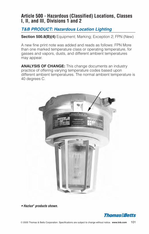
© 2005 Thomas & Betts Corporation. Specifications are subject to change without notice. www.tnb.com 101
Article 500 - Hazardous (Classified) Locations, ClassesI, II, and III, Divisions 1 and 2
T&B PRODUCT: Hazardous Location Lighting
Section 500.8(B)(4) Equipment; Marking; Exception 2; FPN (New)
A new fine print note was added and reads as follows: FPN Morethan one marked temperature class or operating temperature, forgasses and vapors, dusts, and different ambient temperaturesmay appear.
ANALYSIS OF CHANGE: This change documents an industrypractice of offering varying temperature codes based upondifferent ambient temperatures. The normal ambient temperature is40 degrees C.
• Hazlux® products shown.
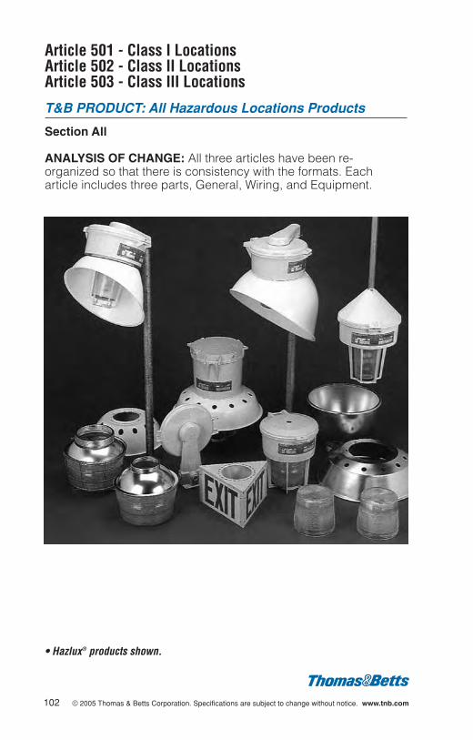
Article 501 - Class I Locations Article 502 - Class II LocationsArticle 503 - Class III Locations
T&B PRODUCT: All Hazardous Locations Products
Section All
ANALYSIS OF CHANGE: All three articles have been re-organized so that there is consistency with the formats. Eacharticle includes three parts, General, Wiring, and Equipment.
102 © 2005 Thomas & Betts Corporation. Specifications are subject to change without notice. www.tnb.com
• Hazlux® products shown.

© 2005 Thomas & Betts Corporation. Specifications are subject to change without notice. www.tnb.com 103
Article 501 - Class I Locations
T&B PRODUCT: All Hazardous Locations Products
Section 501.5 General
Equipment listed and marked in accordance with 505.9(C)(2) foruse in Class I Zone 0, 1, or 2 locations shall be permitted in Class IDivision 1 or 2 locations for the same gas and with a suitabletemperature class.
ANALYSIS OF CHANGE: This is a further expansion of theacceptance of Zone rated products. This European origin systemis gaining popularity in North America.
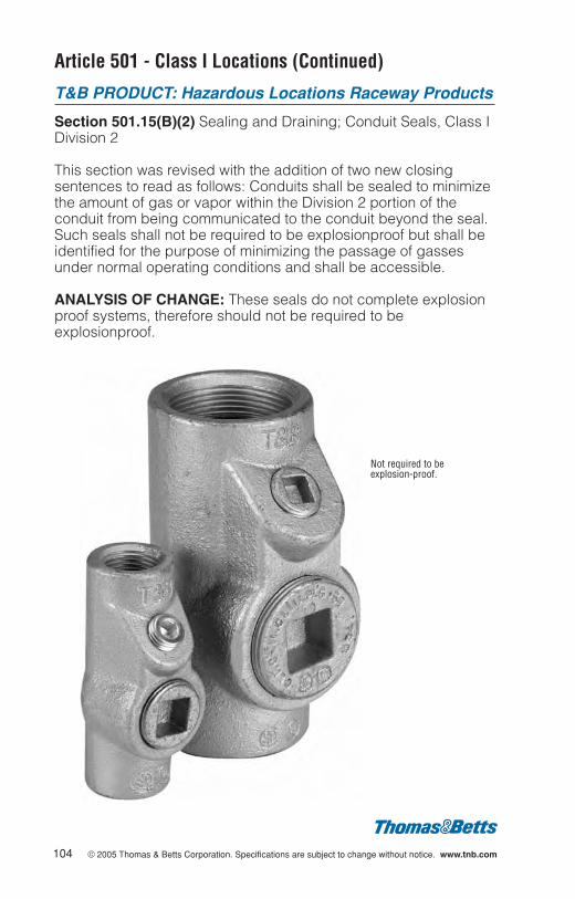
Article 501 - Class I Locations (Continued)
T&B PRODUCT: Hazardous Locations Raceway Products
Section 501.15(B)(2) Sealing and Draining; Conduit Seals, Class IDivision 2
This section was revised with the addition of two new closingsentences to read as follows: Conduits shall be sealed to minimizethe amount of gas or vapor within the Division 2 portion of theconduit from being communicated to the conduit beyond the seal.Such seals shall not be required to be explosionproof but shall beidentified for the purpose of minimizing the passage of gassesunder normal operating conditions and shall be accessible.
ANALYSIS OF CHANGE: These seals do not complete explosionproof systems, therefore should not be required to beexplosionproof.
104 © 2005 Thomas & Betts Corporation. Specifications are subject to change without notice. www.tnb.com
Not required to beexplosion-proof.
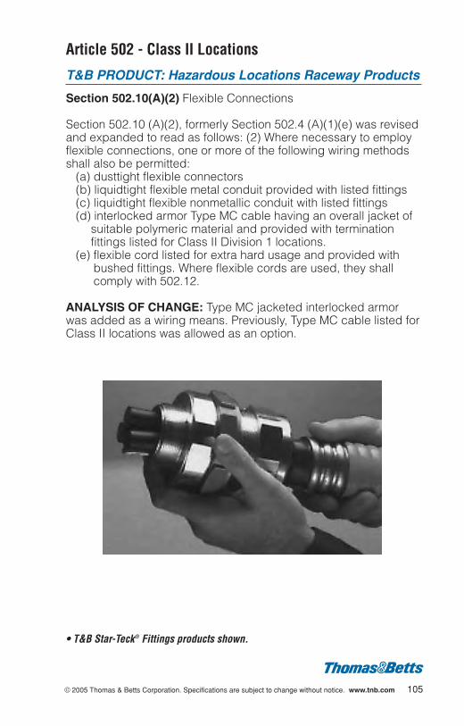
© 2005 Thomas & Betts Corporation. Specifications are subject to change without notice. www.tnb.com 105
Article 502 - Class II Locations
T&B PRODUCT: Hazardous Locations Raceway Products
Section 502.10(A)(2) Flexible Connections
Section 502.10 (A)(2), formerly Section 502.4 (A)(1)(e) was revisedand expanded to read as follows: (2) Where necessary to employflexible connections, one or more of the following wiring methodsshall also be permitted:
(a) dusttight flexible connectors(b) liquidtight flexible metal conduit provided with listed fittings(c) liquidtight flexible nonmetallic conduit with listed fittings(d) interlocked armor Type MC cable having an overall jacket of
suitable polymeric material and provided with terminationfittings listed for Class II Division 1 locations.
(e) flexible cord listed for extra hard usage and provided withbushed fittings. Where flexible cords are used, they shallcomply with 502.12.
ANALYSIS OF CHANGE: Type MC jacketed interlocked armorwas added as a wiring means. Previously, Type MC cable listed forClass II locations was allowed as an option.
• T&B Star-Teck® Fittings products shown.

Article 506 - Zone 20, 21, and 22 Locations forFlammable Dusts, Fibers, and Flyings
T&B PRODUCT: All Hazardous Locations Products
Article All (New)
A new Article, utilizing Zone classifications is introduced to coverHazardous (Classified) Locations where fire and explosion hazardsmay exist due to combustible dusts or ignitable fibers or flyings.
Zone 20 - Continuously present or for long periods of time.Protection Methods-Dust ignition proof, intrinsically safe Wiring Methods - Same as Class II Division 1
Zone 21 - Likely to exist under normal operating conditions.Protection Methods - Dust ignition proof, intrinsically safe,pressurized, Wiring Methods - Same as Class II Division 1
Zone 22 - Not likely to exist under normal operating conditions. Protection Methods - Dust ignition proof, intrinsically safe,pressurized, dust-tight, non-incentiveWiring Methods - Same as Class II Division 2
ANALYSIS OF CHANGE: This is a further expansion of the IECorigin protection systems used for hazardous (classified) locations.An overview of the new alternate system includes:
1. This is an alternative to the Division system of articles 500,502, and 503.
2. There are no groups within the Zones, such as EFG.3. No metal dusts are within the scope of this new protection
system. All group E dusts will use the existing Division systemin article 502.
4. This is a modified system based upon IEC 61241-10.Manufacturers can specify the depth of dust/flyings coverageon a product, such as 25 mm. The Division based systemrequires the max coverage the product can support.
5. The system treats dusts the same as flyings.6. There is no requirement for PE supervision of the area.
106 © 2005 Thomas & Betts Corporation. Specifications are subject to change without notice. www.tnb.com
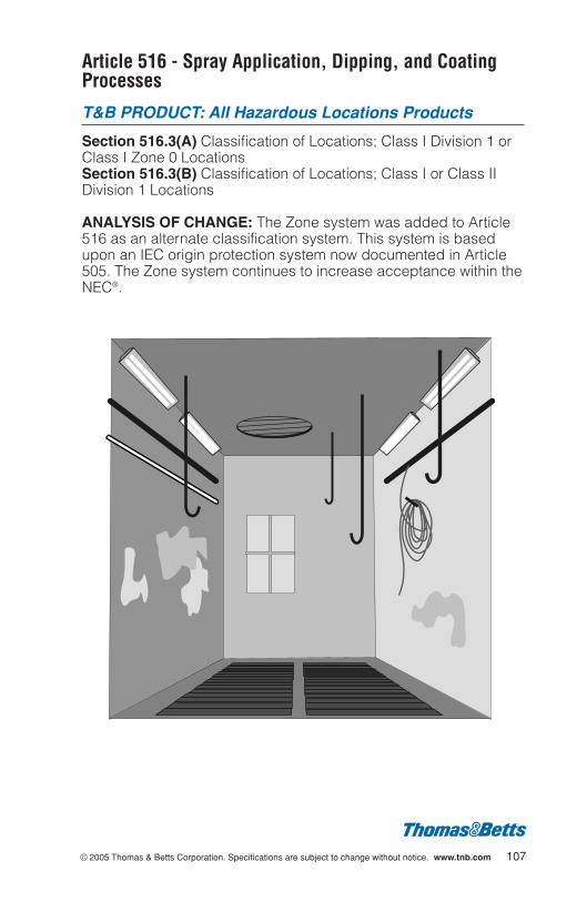
© 2005 Thomas & Betts Corporation. Specifications are subject to change without notice. www.tnb.com 107
Article 516 - Spray Application, Dipping, and CoatingProcesses
T&B PRODUCT: All Hazardous Locations Products
Section 516.3(A) Classification of Locations; Class I Division 1 orClass I Zone 0 Locations Section 516.3(B) Classification of Locations; Class I or Class IIDivision 1 Locations
ANALYSIS OF CHANGE: The Zone system was added to Article516 as an alternate classification system. This system is basedupon an IEC origin protection system now documented in Article505. The Zone system continues to increase acceptance within theNEC®.
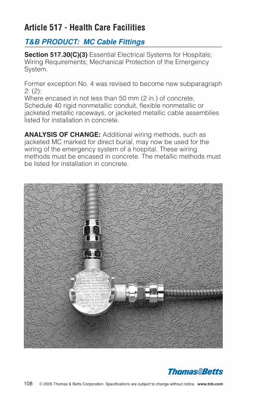
Article 517 - Health Care Facilities
T&B PRODUCT: MC Cable Fittings
Section 517.30(C)(3) Essential Electrical Systems for Hospitals;Wiring Requirements; Mechanical Protection of the EmergencySystem.
Former exception No. 4 was revised to become new subparagraph2: (2):Where encased in not less than 50 mm (2 in.) of concrete,Schedule 40 rigid nonmetallic conduit, flexible nonmetallic orjacketed metallic raceways, or jacketed metallic cable assemblieslisted for installation in concrete.
ANALYSIS OF CHANGE: Additional wiring methods, such asjacketed MC marked for direct burial, may now be used for thewiring of the emergency system of a hospital. These wiringmethods must be encased in concrete. The metallic methods mustbe listed for installation in concrete.
108 © 2005 Thomas & Betts Corporation. Specifications are subject to change without notice. www.tnb.com
© 2005 Thomas & Betts Corporation. Specifications are subject to change without notice. www.tnb.com 109
Article 518 - Assembly Occupancies
T&B PRODUCT: General
Section 518.4(C) Wiring Methods; Spaces with Finish Rating
The title of the article was changed from “Places of Assembly” to“Assembly Occupancies”. College and university classrooms,drinking establishments, passenger stations and terminals of air,surface, underground, and marine public transportation facilitieshave all been removed from the list of locations where electricalnonmetallic tubing and rigid nonmetallic conduit may be used inspaces with finish rating.
ANALYSIS OF CHANGE: This is a reduction in usage for electricalnonmetallic tubing (ENT) and rigid nonmetallic conduit (RNC). Thehigh profile nightclub fires were cited in the substantiation for thischange.
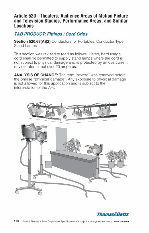
Article 520 - Theaters, Audience Areas of Motion Pictureand Television Studios, Performance Areas, and SimilarLocations
T&B PRODUCT: Fittings / Cord Grips
Section 520.68(A)(2) Conductors for Portables; Conductor Type;Stand Lamps
This section was revised to read as follows: Listed, hard usagecord shall be permitted to supply stand lamps where the cord isnot subject to physical damage and is protected by an overcurrentdevice rated at not over 20 amperes.
ANALYSIS OF CHANGE: The term “severe” was removed beforethe phrase “physical damage”. Any exposure to physical damageis not allowed for this application and is subject to theinterpretation of the AHJ.
110 © 2005 Thomas & Betts Corporation. Specifications are subject to change without notice. www.tnb.com
© 2005 Thomas & Betts Corporation. Specifications are subject to change without notice. www.tnb.com 111
Article 547 - Agricultural Buildings
T&B PRODUCT: Outlet Boxes and Covers
Section 547.5 (G)(1)(d) Wiring Methods; Receptacles
The areas requiring GFCI protection were expanded to include dirtconfinement areas for livestock and the Section was restructuredto read:
(G) General Purpose Receptacles. All 125-volt, single phase, 15-and 20- ampere general purpose receptacles installed in thefollowing locations shall have ground-fault circuit-interrupterprotection for personnel:
(1) In areas having an equipotential plane (2) Outdoors(3) Damp or wet locations(4) Dirt confinement areas for livestock
ANALYSIS OF CHANGE: This requirement has been moved andrevised as the result of changes in 547.10(B). Previously, allbranch circuits providing power to equipment that was accessibleto animals in dirt confinement areas were required to have GFCIprotection. The requirement for GFCI now only applies to 125-volt,single phase, 15- and 20- ampere general- purpose receptacles inthese areas. Dirt confinement areas were not required to have anequipotential plane grounding system installed. Loss of use due tonuisance tripping of a GFCI on circuits feeding unattendedequipment essential to the well being of livestock is seen as agreater hazard than the potential shock hazard to the livestock andhumans in the event of an electrical fault. The result of this changewill influence the demand for larger boxes and covers to houseGFCI receptacles.
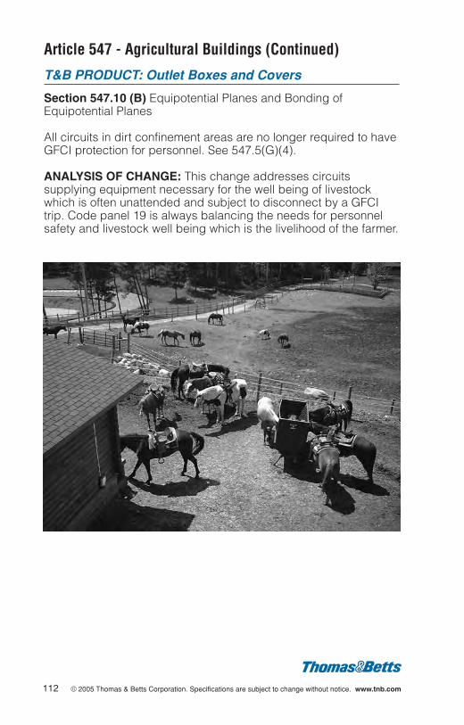
112 © 2005 Thomas & Betts Corporation. Specifications are subject to change without notice. www.tnb.com
Article 547 - Agricultural Buildings (Continued)
T&B PRODUCT: Outlet Boxes and Covers
Section 547.10 (B) Equipotential Planes and Bonding ofEquipotential Planes
All circuits in dirt confinement areas are no longer required to haveGFCI protection for personnel. See 547.5(G)(4).
ANALYSIS OF CHANGE: This change addresses circuitssupplying equipment necessary for the well being of livestockwhich is often unattended and subject to disconnect by a GFCItrip. Code panel 19 is always balancing the needs for personnelsafety and livestock well being which is the livelihood of the farmer.
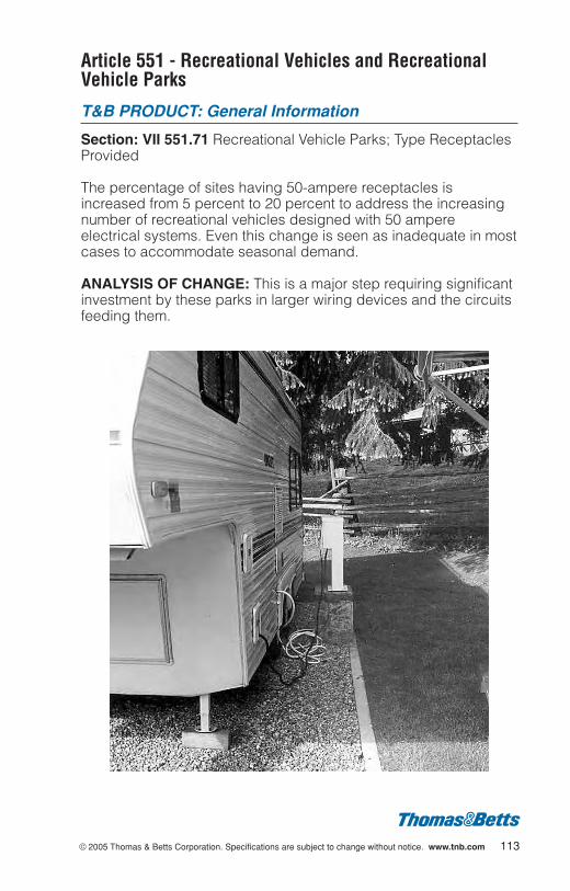
© 2005 Thomas & Betts Corporation. Specifications are subject to change without notice. www.tnb.com 113
Article 551 - Recreational Vehicles and RecreationalVehicle Parks
T&B PRODUCT: General Information
Section: VII 551.71 Recreational Vehicle Parks; Type ReceptaclesProvided
The percentage of sites having 50-ampere receptacles isincreased from 5 percent to 20 percent to address the increasingnumber of recreational vehicles designed with 50 ampereelectrical systems. Even this change is seen as inadequate in mostcases to accommodate seasonal demand.
ANALYSIS OF CHANGE: This is a major step requiring significantinvestment by these parks in larger wiring devices and the circuitsfeeding them.
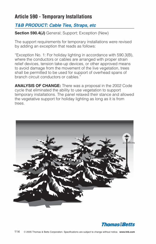
114 © 2005 Thomas & Betts Corporation. Specifications are subject to change without notice. www.tnb.com
Article 590 - Temporary Installations
T&B PRODUCT: Cable Ties, Straps, etc
Section 590.4(J) General; Support; Exception (New)
The support requirements for temporary installations were revisedby adding an exception that reads as follows:
“Exception No. 1: For holiday lighting in accordance with 590.3(B),where the conductors or cables are arranged with proper strainrelief devices, tension take-up devices, or other approved meansto avoid damage from the movement of the live vegetation, treesshall be permitted to be used for support of overhead spans ofbranch circuit conductors or cables.”
ANALYSIS OF CHANGE: There was a proposal in the 2002 Codecycle that eliminated the ability to use vegetation to supporttemporary installations. The panel relaxed their stance and allowedthe vegetative support for holiday lighting as long as it is fromtrees.
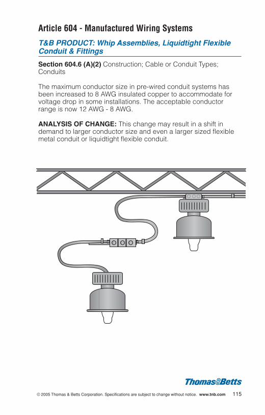
© 2005 Thomas & Betts Corporation. Specifications are subject to change without notice. www.tnb.com 115
Article 604 - Manufactured Wiring Systems
T&B PRODUCT: Whip Assemblies, Liquidtight FlexibleConduit & Fittings
Section 604.6 (A)(2) Construction; Cable or Conduit Types;Conduits
The maximum conductor size in pre-wired conduit systems hasbeen increased to 8 AWG insulated copper to accommodate forvoltage drop in some installations. The acceptable conductorrange is now 12 AWG - 8 AWG.
ANALYSIS OF CHANGE: This change may result in a shift indemand to larger conductor size and even a larger sized flexiblemetal conduit or liquidtight flexible conduit.
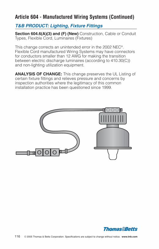
Article 604 - Manufactured Wiring Systems (Continued)
T&B PRODUCT: Lighting, Fixture Fittings
Section 604.6(A)(3) and (F) (New) Construction, Cable or ConduitTypes, Flexible Cord, Luminaires (Fixtures)
This change corrects an unintended error in the 2002 NEC®.Flexible Cord manufactured Wiring Systems may have connectorsfor conductors smaller than 12 AWG for making the transitionbetween electric discharge luminaires (according to 410.30(C))and non-lighting utilization equipment.
ANALYSIS OF CHANGE: This change preserves the UL Listing ofcertain fixture fittings and relieves pressure and concerns byinspection authorities where the legitimacy of this commoninstallation practice has been questioned since 1999.
116 © 2005 Thomas & Betts Corporation. Specifications are subject to change without notice. www.tnb.com
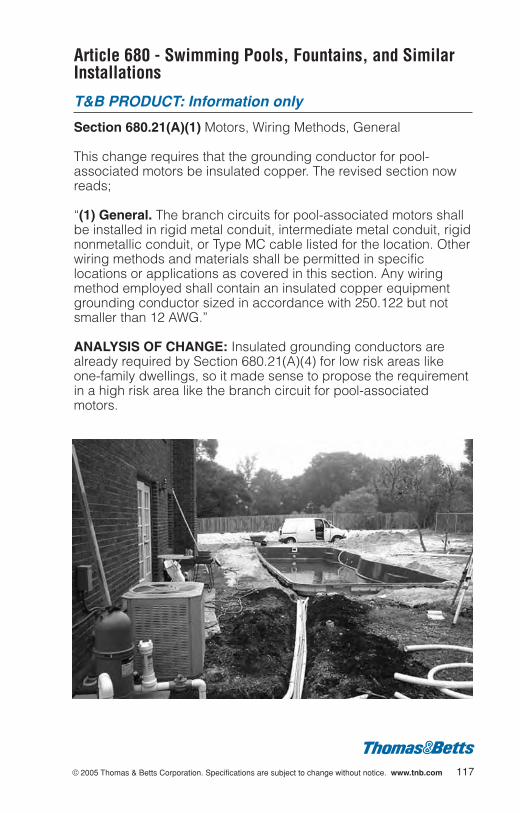
© 2005 Thomas & Betts Corporation. Specifications are subject to change without notice. www.tnb.com 117
Article 680 - Swimming Pools, Fountains, and SimilarInstallations
T&B PRODUCT: Information only
Section 680.21(A)(1) Motors, Wiring Methods, General
This change requires that the grounding conductor for pool-associated motors be insulated copper. The revised section nowreads;
“(1) General. The branch circuits for pool-associated motors shallbe installed in rigid metal conduit, intermediate metal conduit, rigidnonmetallic conduit, or Type MC cable listed for the location. Otherwiring methods and materials shall be permitted in specificlocations or applications as covered in this section. Any wiringmethod employed shall contain an insulated copper equipmentgrounding conductor sized in accordance with 250.122 but notsmaller than 12 AWG.”
ANALYSIS OF CHANGE: Insulated grounding conductors arealready required by Section 680.21(A)(4) for low risk areas likeone-family dwellings, so it made sense to propose the requirementin a high risk area like the branch circuit for pool-associatedmotors.
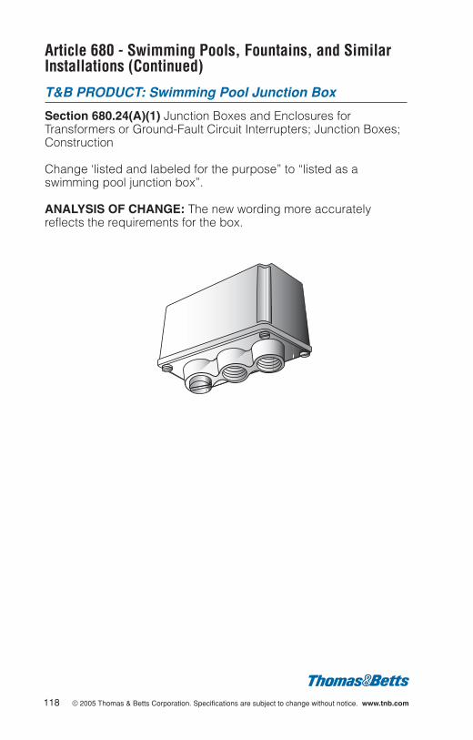
Article 680 - Swimming Pools, Fountains, and SimilarInstallations (Continued)
T&B PRODUCT: Swimming Pool Junction Box
Section 680.24(A)(1) Junction Boxes and Enclosures forTransformers or Ground-Fault Circuit Interrupters; Junction Boxes;Construction
Change ‘listed and labeled for the purpose” to “listed as aswimming pool junction box”.
ANALYSIS OF CHANGE: The new wording more accuratelyreflects the requirements for the box.
118 © 2005 Thomas & Betts Corporation. Specifications are subject to change without notice. www.tnb.com
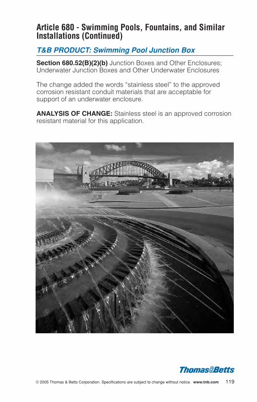
© 2005 Thomas & Betts Corporation. Specifications are subject to change without notice. www.tnb.com 119
Article 680 - Swimming Pools, Fountains, and SimilarInstallations (Continued)
T&B PRODUCT: Swimming Pool Junction Box
Section 680.52(B)(2)(b) Junction Boxes and Other Enclosures;Underwater Junction Boxes and Other Underwater Enclosures
The change added the words “stainless steel” to the approvedcorrosion resistant conduit materials that are acceptable forsupport of an underwater enclosure.
ANALYSIS OF CHANGE: Stainless steel is an approved corrosionresistant material for this application.
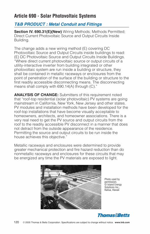
Article 690 - Solar Photovoltaic Systems
T&B PRODUCT : Metal Conduit and Fittings
Section IV. 690.31(E)(New) Wiring Methods; Methods Permitted;Direct Current Photovoltaic Source and Output Circuits InsideBuilding.
The change adds a new wiring method (E) covering DCPhotovoltaic Source and Output Circuits inside buildings to read:(E) DC Photovoltaic Source and Output Circuits Inside Buildings.“Where direct current photovoltaic source or output circuits of autility-interactive inverter from building integrated or otherphotovoltaic system are run inside a building or structure, theyshall be contained in metallic raceways or enclosures from thepoint of penetration of the surface of the building or structure to thefirst readily accessible disconnecting means. The disconnectingmeans shall comply with 690.14(A) through (C).”
ANALYSIS OF CHANGE: Submitters of this requirement notedthat “roof-top residential (solar photovoltaic) PV systems are goingmainstream in California, New York, New Jersey and other states.PV modules and installation methods have been developed for theroof-top installations that have become visually acceptable tohomeowners, architects, and homeowner associations. There is avery real need to get the PV source and output circuits from theroof to the readily accessible PV disconnect in a manner that doesnot detract from the outside appearance of the residence.Permitting the source and output circuits to be run inside thehouse achieves this objective.”
Metallic raceways and enclosures were determined to providegreater mechanical protection and fire hazard reduction than dononmetallic raceways and enclosures for these circuits that maybe energized any time the PV materials are exposed to light.
120 © 2005 Thomas & Betts Corporation. Specifications are subject to change without notice. www.tnb.com
Photo used bypermission.© Island EnergySolutions Inc.,Kailua, Hawaii
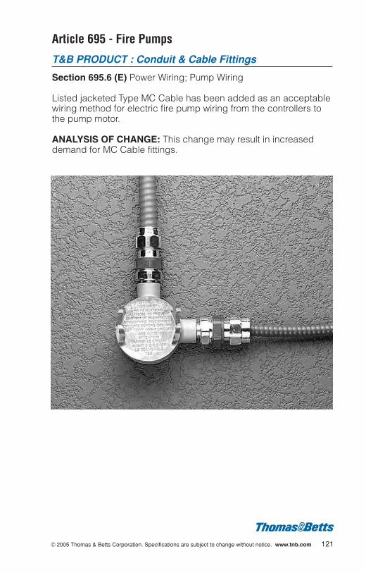
© 2005 Thomas & Betts Corporation. Specifications are subject to change without notice. www.tnb.com 121
Article 695 - Fire Pumps
T&B PRODUCT : Conduit & Cable Fittings
Section 695.6 (E) Power Wiring; Pump Wiring
Listed jacketed Type MC Cable has been added as an acceptablewiring method for electric fire pump wiring from the controllers tothe pump motor.
ANALYSIS OF CHANGE: This change may result in increaseddemand for MC Cable fittings.
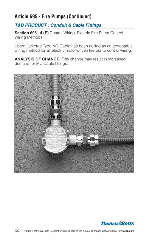
Article 695 - Fire Pumps (Continued)
T&B PRODUCT : Conduit & Cable Fittings
Section 695.14 (E) Control Wiring; Electric Fire Pump ControlWiring Methods
Listed jacketed Type MC Cable has been added as an acceptablewiring method for all electric motor-driven fire pump control wiring.
ANALYSIS OF CHANGE: This change may result in increaseddemand for MC Cable fittings.
122 © 2005 Thomas & Betts Corporation. Specifications are subject to change without notice. www.tnb.com
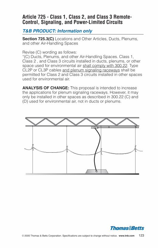
© 2005 Thomas & Betts Corporation. Specifications are subject to change without notice. www.tnb.com 123
Article 725 - Class 1, Class 2, and Class 3 Remote-Control, Signaling, and Power-Limited Circuits
T&B PRODUCT: Information only
Section 725.3(C) Locations and Other Articles, Ducts, Plenums,and other Air-Handling Spaces
Revise (C) wording as follows:“(C) Ducts, Plenums, and other Air-Handling Spaces. Class 1,Class 2 , and Class 3 circuits installed in ducts, plenums, or otherspace used for environmental air shall comply with 300.22. TypeCL2P or CL3P cables and plenum signaling raceways shall bepermitted for Class 2 and Class 3 circuits installed in other spacesused for environmental air.
ANALYSIS OF CHANGE: This proposal is intended to increasethe applications for plenum signaling raceways. However, it mayonly be installed in other spaces as described in 300.22 (C) and(D) used for environmental air, not in ducts or plenums.
Article 770 - Optical Fiber Cables and Raceways
T&B PRODUCT: Information only
Section 770.6 Raceways for Optical Fiber Cables
This change turns the exception into positive language and adds areference to 770.53, Applications of Listed Optical Fiber Cables andRaceways. The change is editorial in nature and reads as follows:
“770.6 Raceways for Optical Fiber Cables. Installation of racewaysshall comply with (A) through (D) below:(A) Chapter 3 Raceways. Listed optical fiber cable shall be
permitted to be installed in any type of listed racewaypermitted in Chapter 3 where that listed raceway is installed inaccordance with Chapter 3. Where optical fiber cables areinstalled within raceway without current-carrying conductors,the raceway fill tables of Chapter 3 and Chapter 9 shall notapply. Where nonconductive optical fiber cables are installedwith electric conductors in a raceway, the raceway fill tables ofChapter 3 and Chapter 9 will apply.
(B) Optical Fiber Raceways. Listed optical fiber cable shall bepermitted to be installed in listed plenum optical fiber raceway,listed riser optical fiber raceway or listed general purposeoptical fiber raceway installed in accordance with 770.61 and362.24 through 362.56, where the requirements applicable toelectrical nonmetallic tubing shall apply.
(C) Innerduct. Listed plenum optical fiber raceway, listed riseroptical fiber raceway or listed general purpose optical fiberraceway installed in accordance with 770.61 shall be permittedto be installed in innerduct in any type of listed racewaypermitted in Chapter 3.
(D) Entering Buildings. Unlisted underground or outside plant con-struction plastic innerduct entering the building from the outsidewall shall be terminated and firestopped at the point of entrance.
ANALYSIS OF CHANGE: These changes are editorial, butpromote the use of nonmetallic raceways for optical fiber cables.
124 © 2005 Thomas & Betts Corporation. Specifications are subject to change without notice. www.tnb.com
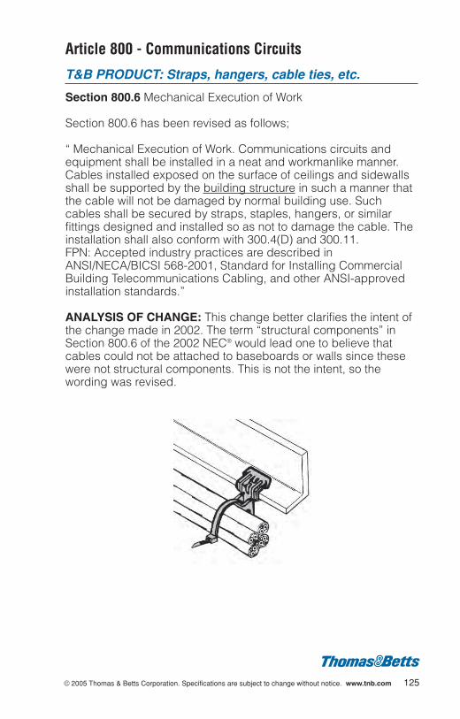
© 2005 Thomas & Betts Corporation. Specifications are subject to change without notice. www.tnb.com 125
Article 800 - Communications Circuits
T&B PRODUCT: Straps, hangers, cable ties, etc.
Section 800.6 Mechanical Execution of Work
Section 800.6 has been revised as follows;
“ Mechanical Execution of Work. Communications circuits andequipment shall be installed in a neat and workmanlike manner.Cables installed exposed on the surface of ceilings and sidewallsshall be supported by the building structure in such a manner thatthe cable will not be damaged by normal building use. Suchcables shall be secured by straps, staples, hangers, or similarfittings designed and installed so as not to damage the cable. Theinstallation shall also conform with 300.4(D) and 300.11.FPN: Accepted industry practices are described inANSI/NECA/BICSI 568-2001, Standard for Installing CommercialBuilding Telecommunications Cabling, and other ANSI-approvedinstallation standards.”
ANALYSIS OF CHANGE: This change better clarifies the intent ofthe change made in 2002. The term “structural components” inSection 800.6 of the 2002 NEC® would lead one to believe thatcables could not be attached to baseboards or walls since thesewere not structural components. This is not the intent, so thewording was revised.

Article 800 - Communications Circuits (Continued)
T&B PRODUCT: Information only
Section 800.52(A)(1)(c) Exception No. 1 Installation ofCommunications Wires, Cables, and Equipment; Separation fromOther Conductors; In Raceways, Boxes, and Cables
This change mandates that the barrier is a permanent part of theenclosure or that a removable divider that has been listed may beused to divide the power and communications circuits.
ANALYSIS OF CHANGE: This change indicates that the barriermay be permanently installed or a listed field installed barrier.
126 © 2005 Thomas & Betts Corporation. Specifications are subject to change without notice. www.tnb.com
• Steel City® Surface Raceway products shown.
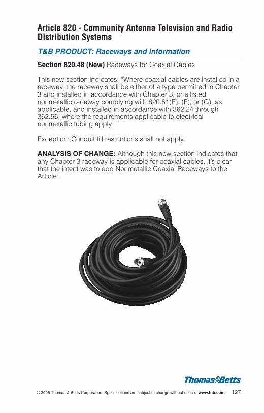
© 2005 Thomas & Betts Corporation. Specifications are subject to change without notice. www.tnb.com 127
Article 820 - Community Antenna Television and RadioDistribution Systems
T&B PRODUCT: Raceways and Information
Section 820.48 (New) Raceways for Coaxial Cables
This new section indicates: “Where coaxial cables are installed in araceway, the raceway shall be either of a type permitted in Chapter3 and installed in accordance with Chapter 3, or a listednonmetallic raceway complying with 820.51(E), (F), or (G), asapplicable, and installed in accordance with 362.24 through362.56, where the requirements applicable to electricalnonmetallic tubing apply.
Exception: Conduit fill restrictions shall not apply.
ANALYSIS OF CHANGE: Although this new section indicates thatany Chapter 3 raceway is applicable for coaxial cables, it’s clearthat the intent was to add Nonmetallic Coaxial Raceways to theArticle.
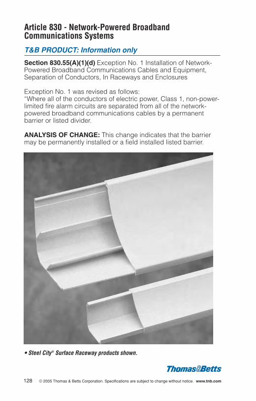
Article 830 - Network-Powered BroadbandCommunications Systems
T&B PRODUCT: Information only
Section 830.55(A)(1)(d) Exception No. 1 Installation of Network-Powered Broadband Communications Cables and Equipment,Separation of Conductors, In Raceways and Enclosures
Exception No. 1 was revised as follows:“Where all of the conductors of electric power, Class 1, non-power-limited fire alarm circuits are separated from all of the network-powered broadband communications cables by a permanentbarrier or listed divider.
ANALYSIS OF CHANGE: This change indicates that the barriermay be permanently installed or a field installed listed barrier.
128 © 2005 Thomas & Betts Corporation. Specifications are subject to change without notice. www.tnb.com
• Steel City® Surface Raceway products shown.


