Embed Size (px)
Citation preview


TABLE OF CONTENTSSUBJECT PAGE
INTRODUCTION ............................................................................................................1
TECHNICAL DATA...........................................................................................................2-3
INSTALLATION INSTRUCTIONS.....................................................................................4-5
SCALER OPERATION .....................................................................................................6
ULTRASONIC SCALING PROCEDURES........................................................................6-7
SCALER MAINTENANCE................................................................................................7-8
STACK INSTALLATION / REMOVAL ...............................................................................9
SONUS ULTRASONIC SCALING TIPS...........................................................................10
POLISHER INSTALLATION .............................................................................................11
POLISHER OPERATION..................................................................................................12
POLISHER MAINTENANCE............................................................................................13
STRAIGHT HANDPIECE MAINTENANCE.......................................................................15-16
MICROMOTOR MAINTENANCE.....................................................................................16
SCALER TROUBLESHOOTING .....................................................................................17
POLISHER TROUBLESHOOTING ..................................................................................18
WATER FILTER CLEANING INSTRUCTIONS .................................................................19
SON MATE OPTIONAL ACCESSORIES .........................................................................20
FRICTION GRIP CONTRA ANGLE MAINTENANCE.......................................................21-22
OPTIONAL BURS............................................................................................................23
SADDLE VALVE ASSEMBLY INSTRUCTIONS................................................................24-25
WATER TANK INSTRUCTIONS.......................................................................................26
WATER TANK CARE & MAINTENANCE .........................................................................26-27
DIAMOND DISK OPERATING INSTRUCTIONS..............................................................28
CARE FOR YOUR MAINTENANCE FREE-ANGLE .........................................................29
OPTIONAL SON-MATE DENTAL ACCESSORIES ..........................................................30
WARRANTY ....................................................................................................................31
RETURN FOR EVALUATION/REPAIR FORM..................................................................32
REQUEST LOANER FORM.............................................................................................33
INTRODUCTION:
Thank you for purchasing an Engler Son-Mate Scaler Polisher combination.
The design of the Engler Engineering Corporation, Son-Mate scaler circuitry combinesIntegrated Phase Lock Loop technology along with our time tested delayed cavitationcircuitry. This combination produces a powerful and potent tool against periodontal disease.A reinforced solid aluminum chassis surrounds the internal circuit board, providing a verydurable and reliable unit.
The dental scaler utilizes an ultrasonic principle of operation. The internal circuitry convertsordinary line voltage to an operating frequency of approximately 18,000 Hz. This frequencyis then amplified and delivered to the scaling tip. As a result, the tip vibrates at this ultrasonicfrequency with an amplitude of 0.001 to 0.004 in. (25.4 um to 102 um).
In designing our unique Engler tips, water flows internally through the tip as it vibrates. Asthe bubbles in the lavage are bacteriocidal, the energy released collapses and destroys thebacterial cell walls. The water flowing internally through the tip, effectively cools the area andassists in removing any debris from the operative site
IMPORTANT:We recommend that ultrasonic scalers should not be used by or in close proximity toanyone who has any electronic implant device (pacemaker, defibrillator, or has anyneurological problems).
PLEASE READ VERY CAREFULLY
Engler Engineering Corporation makes every effort to verify that all parts for the unit alongwith any optional accessories shipped from our location are included in your order. It isimperative that you inspect the package and if you find any pieces missing or damaged,you must notify us immediately.
All devices manufactured by Engler Engineering are built and tested to approvedstandards. Any modification to the device, cables or hoses, initiated by others nullifies allwarranty statements. Engler Engineering Corporation will not be held liable for anydamage, injury or death due to non-authorized service and / or improper installation ofthe device.
If you have any questions or comments, please contact:
Engler Engineering Corporation1099 East 47th StreetHialeah, Florida 33013
800-445-8581 – 305-688-8581 – FAX 305-685-7671
1

TECHNICAL DATA:
I. SCALER:
Input Voltage: 120 240 VACInput Frequency: 50/60 Hz. 50/60 Hz.Current (Amperes) 1.2 0.6
IMPORTANT: Your Son-Mate has been pre-set to the voltage as requested in you orderand will not require adjustments in this regard. The voltage of operation is indicated on thelast line of the label on rear panel of your unit.
Transducer Style: MagnetostrictiveOperating Frequency: 17,000-19,000 Hz.
Ultrasonic Generator Data-Auto-Tuned Feedback OscillatorVariable Amplitude Power ControlPulse Modulation Output
II. WATER:
Input Pressure: 30 PSI (min.)60 PSI (max)
III. POLISHER:
Power Control: Variable Voltage StyleOutput Voltage: 3 - 30 VDCOutput Current: 5 Amperes (max)
IV. MICROMOTOR:
Velocity Range: 300 - 35,000 RPMStyle: Sealed BearingBrush Design: Fully Replaceable
V. STRAIGHT HANDPIECE:
Maximum Drive Velocity: 30,000 RPMStyle: Sealed Bearing
Twist Lock Collet
2

TECHNICAL DATA: (cont.)
VI: PROPHY ANGLE:
Recommended Drive Velocity: 5,000 - 6,000 RPMType: Sealed Bearing/Open Bushing
IMPORTANT: Since the gears and bushings of the Prophy Angle are of a open design theyMUST be kept clean and lubricated daily to insure long life.
VII. DIMENSIONS:
CHASSIS:
Length: 9 in. (23 cm)Width: 8 in. (20 cm)Height: 3.3 in. (8.4 cm)
VIII. ACCESSORIES:
Handpiece Cable: 96 in. (244 cm)Footswitch Cable: 96 in. (244 cm)Power Cord: 72 in. (183 cm)Water Line: 96 in. (244 cm)
NET WEIGHT: 8 1/2 Lbs. (3.85 Kg.)
SHIPPING WEIGHT: 10 Lbs. (4.5 Kg.)
3

INSTALLATION INSTRUCTIONS:
Before installing or operating your new Son-Mate, carefully read and follow all of theinstructions.
IMPORTANT: The Son-Mate must be connected to a clean, filtered, water supply, capableof delivering 30 to 60 psi (2.0 to 4.2 kg/cm2) of water input pressure. This unit comes with anIn-Line water filter (P/N: A52030). When kept clean and free of foreign matter, it will assist inproper water flow to the unit. If the water pressure in your office is above 60 psi, we recommend you install a waterpressure regulator on the supply line to your scaler.
CONNECTING WATER SUPPLY:We strongly recommend that a manual shut off valve be placed prior to the Female QuickDisconnect, so that the water can be completely shut-off, and line pressure relieved, whenthe unit is not in use.
The Son-Mate comes equipped with an 8 foot (244 cm)water line with a male Poly-Quick disconnect fitting. Thewater line may be connected to your water source inmany different ways. We offer four suggestions:
It is imperative that you disconnect the device fromthe water supply when it is not in operation.
1. Female Quick Disconnect (P/N: 44300) - This isthe female mating connector to the male quickdisconnect supplied with the Son-Mate. Usethis to create a custom water installation.
2. Saddle Valve Assembly (P/N: A44303) - This kitcontains all parts to quickly and easily connect yourunit to an existing cold water supply line.
44301 Male quick disconnect** Please note male quick disconnect is supplied as astandard item with all Engler dental units
44300 Female quick disconnect
A-44303 Saddle valveassembly w/femaleconnector & tubing
4

3. Faucet Adapter Assembly (P/N: A22303) Thisscrews on the faucet and has a female mating connector.
4. Portable Water Tank (P/N: PT-1) - This is a selfcontained water source which is suited ideallyfor portable operation. All you do is fill tankwith distilled water, pressurize the tank, andbegin scaling.
IMPORTANT: If you do not feel comfortable doing thewater installation yourself, we highly recommend theservices of a professional plumber. Engler EngineeringCorporation will not be held liable for any damageincluding, but not limited to leakage caused by improperinstallation of our products.
CONNECTING POWER SUPPLY:Plug the power cord into a grounded power outlet. DO NOT remove or bypass the groundpin from the power cord of this device.
IMPORTANT: Your Son-Mate has been pre-set to the voltage as requested in you orderand will not require adjustments in this regard. The voltage of operation is indicated on therear panel of your unit.
PT-1 Portable water tank (one gallon)
5
A-22303 Faucet attachmentw/female connector & tubing

SCALER OPERATING INSTRUCTIONS:
Initial procedures at the start of every day!
1. Make sure the water is turned on and flowing to the Son-Mate.2. Rotate the Selector Switch to the “SCALER” position, the red LED
indicator should light up, showing that you have power to the unit.3. Adjust the power control knob to the minimum power setting fully counter-clockwise.
NOTE: The transducer (stack) has already been installed into the hand- piece, please do not remove it at this time.
4. With only the transducer (stack) in the handpiece (no tip installed), set the WATERCONTROL to its maximum setting by rotating it counterclockwise, hold the handpieceover a cuspidor or sink and depress the footswitch until water comes out in a stream.This should take a few seconds. This step is done to insure proper operation of the delaycavitation feature by removing air that may be trapped in the water lines.
5. Insert a sterile tip into the nosecone, and rotate the assembly in a clockwise direction.Then firmly tighten by hand.
IMPORTANT: It is important that you DO NOT over-tighten the tips, as this will damage theStack and / or the tip.
6. Set the power control and the water control to a level where you have a fine mist at thetip.
IMPORTANT: Keep in mind that higher power levels tend to heat the out-flowing water.Temperature control can be achieved by balancing the power with water flow volume. Thus,high power settings require high water flow rates and conversely low power requires lowwater flow rates.
7. The scaler is now ready for use.
ULTRASONIC SCALING PROCEDURES:
1. Before placing tip into patient’s mouth activate the scaler over a sink by depressing thefootswitch. Check for the desired power and water spray.
2. It is recommended that when a tip is placed into a patient’s mouth, the lips, cheek andtongue be retracted to prevent accidental contact.
3. Place the tip into the patient’s mouth and depress the footswitch in order to activate thescaler.
4. Bring the tip lightly up to the tooth and gently move it over the surface of the tooth in acircular motion.
6

IMPORTANT: Pressure on the tip is not necessary to remove calculus or tartar. Enamel onthe teeth may be damaged or removed when using excessive pressure. It can also bedamaged by keeping the tip in one location for a short period of time. Using the tip as a pryto remove calculus or tartar may change the shape of the tip, which in-turn, changes thefrequency. The normal power setting for most procedures should be near mid-range. Sinceevery operator has a different technique and some patient’s are more sensitive than others,the power may be adjusted to satisfy specific requirements. Ultrasonic Scaling Procedures(Tip Application) is not intended for contact with Soft Tissue
CAUTION: Contact with Soft Tissue May Cause Burns.
As with any precision instrument, stacks should be handled carefully. To avoid damage to thestack during insertion, please familiarize yourself with the stack installation on page 10.
The use of a face mask is recommended when operating the scaler, to avoid inhalation ofbacterially contaminated aerosol (water mist) by the operator.
FINAL PROCEDURES AT THE END OF EACH DAY:
1. Switch the unit to the off position.2. Detach the tip and nose cone and sterilize. 3. Disconnect the unit from its water source or turn off the water supply.4. Clean and disinfect all surfaces.
SCALER MAINTENANCE:
Instrument Tips:IMPORTANT: The scaling tips should be thoroughly cleaned and free of blood, tissue, or anyother debris before sterilization.
The scaling tips nosecone and stack may be sterilized by Autoclave or Chemiclave, alwaysfollowing the manufacturer’s instructions and recommendations. Do not autoclave over 270degrees F or more than twenty (20) minutes..
It is recommended that you do not leave tips screwed into the handpiece for several days,as water and sediment may make it difficult to remove, causing possible damage to thestack.
7

Transducer / Stack:The stack may be sterilized using the same methods as listed above. Do not sterilize theentire Stack, Tip and Nosecone assembly as one piece. Separate the tip from the stackbefore sterilization.
To re-install stack into handpiece, follow correct procedures on page 9.
Note: To achieve optimum performance of your equipment, we recommend that the stack,tip and nosecone be replaced every 6 months to a year.
Chassis:The chassis of your unit should be cleaned at the end of every operating day with a chemicalsterilization solution. This procedure could be done by spraying a fine mist of sterilizationsolution on the unit, allowing it to remain on the chassis for the length of time recommendedby the manufacturer. The surface should be wiped with a clean damp cloth or as suggestedby the Chemiclave manufacturer.. Dry completely.
IMPORTANT: In using any chemical sterilization solution please follow the manufacturer’ssuggested procedures.
HANDPIECE, FOOTSWITCH AND POWER CABLES:After each procedure, or at least once a day, it is suggested that the handpiece and its cablebe thoroughly cleaned and sterilized. The recommended procedure is as follows:
1. Remove Tip, and Nosecone - Sterilize these items as listed above.2. Clean the outer surface of the handpiece and its cable with an antiseptic soap, rinse off
with water and sterilize with a chemical sterilization solution.3. Place cleaned Tip and Nosecone into handpiece for next patient.4. The footswitch and power cables should be cleaned periodically by spraying a fine mist
of sterilization or cleaning solution on the cables. It should remain on the cables for thelength of time recommended by the manufacturer. Wipe the surface with a damp clothand dry the cables completely.
FOR HUMAN DENTISTRY:
1. It is recommended that the Stack, Nose Cone and Tip be removed and properly sterilizedafter each patient. This can be done as shown on page 9, however always replace stackby properly lining up the white dot on the handpiece with the small hole on the stack.
2. If using an Autoclave, DO NOT exceed 270 degrees F. for more than 20 minutes ashigher temperatures may reduce the effectiveness of the stack and tip.
8

STACK (TRANSDUCER) INSTALLATION / REMOVAL INSTRUCTIONS
You have purchased a precision instrumentPlease handle gently- It is easily damaged
TO REMOVE THE STACK:
A. Unscrew the scaling tip by turning theplastic nose-cone counterclockwise.
B. Remove tip.C. Pull off plastic nose-cone.
Pull stack straight up . DO NOT USEPLIERS!If you have difficulty pulling up, insert the scaling tip and pull from tip. (IF YOU STILLCANNOT REMOVE IT CALL US AT 800-445-8581)
D. Do not twist or rotate stack while it is in the handpiece as it will damage the stack and /or handpiece.
TO INSTALL THE STACK:
A. Carefully remove the new stack from the clear shipping tube.B. Locate the hole (see photo
above) on side of stack. Alignit with the white dot on thetop of the handpiece and letthe stack slide down into thehandpiece.
C. Gently push the stack downuntil it stops. There should beapproximately 1/2 inchshowing above the handpiece.
D. Push plastic nosecone ontoscaler handpiece.
E. Place Scaling Tip into nose-cone and turn nose-coneclockwise. Tighten securely byhand. DO NOT USE TIPWRENCH.
NOTE: Twisting the nosecone or tip with excessive force will damage the stack.
FOR FURTHER ASSISTANCE CALL CUSTOMER SERVICE800-445-8581 OR 305-688-8581
scaler handpiece shell
white dot nose cone scaling metaltip
insert/transducer/stack
tip wrench(fits on nose cone)
white dot on
handpiecehole on
sideof stack
9

10

POLISHER INSTALLATION:
1. Plug the Micromotor into the front of the control box. This is done by inserting the maleconnector at the end of the Micromotor cable, into the female receptacle on the frontpanel of the unit and rotating the locking collar clockwise.
2. Slide the Straight Handpiece down over the top of the Micromotor.
3. Line up the notch of the Prophy Angle with theAligning Pin on the Straight Handpiece, and thenpush the shaft of the Prophy Angle into thechuck of the Straight Handpiece.
4. Rotate the Lock Ring clockwise, until it clicksand locks the prophy angle in place.
5. Place a disposable rubber polishing cup on theend of the prophy angle by snapping it on. TheProphy Angle is now secured and ready foroperation.
6. Rotate the selector knob on the front of unit toeither forward or reverse operation.
NOTE: When using the polisher the GREEN LED indicator should be on.
NOTE: It is suggested to use a low to mid range speed setting for polishing. High speed will damage the gears in the Prophy angle
SAFETY INFORMATION:
1. Never turn the Lock Ring while the handpiece is in operation.
2. Never reverse the direction of the micromotor while it is in operation. Possible damage tothe unit may occur. Always let the micromotor come to a complete stop before reversingdirections.
3. Do not drop the Micromotor, Handpiece or Prophy Angle on the floor or other hardsurface as the shock may cause malfunction.
4. Do Not lock or run the Micromotor / Straight Handpiece Assembly without a ProphyAngle, Cutting Disk, Contra Angle, or test shaft installed. Doing so could damage theStraight Handpiece and / or Micromotor.
11
Straight Handpiece
Chuck
Prophy AngleAligning Pin
Lock Ring

5. When installing the Prophy Angle or other accessory, make sure that the Lock Ring isrotated fully in the unlock position, otherwise the accessory can not be installed and theStraight Handpiece will not operate.
6. Do Not rotate the selector switch on the front of the control box between Forward andReverse rapidly. Always allow a second between the two selections.
7. As this is a precision instrument, always return it to Engler Engineering Corporation forrepair.
POLISHER OPERATION:
1. Dampen the rubber cup and place a small amount of polishing paste on it.
2. Rotate the POWER control to the minimum setting in the Prophy Range.
3. Depress the footswitch and the rubber cup will begin to rotate. The speed of rotationmay be adjusted to your desired level by readjusting the POWER control.
4. To keep the paste from flying off the cup, maintain a low speed and gently bring the cupup to the tooth before depressing the footswitch
IMPORTANT: The prophy angle is only rated to rotational speeds of 5,000 RPM - therefore,in order to prevent premature failure of the angle keep the unit set in the prophy rangewhenever the prophy angle is attached to the straight handpiece.
5. High speed settings may throw the polishing paste off of the rubber cup. Always startwith a low speed and then adjust to a higher speed as required.
6. Place the end of the angle into the patients’ mouth and gently apply the rubber cup tothe surface of the tooth with a circular motion. Do not allow the rubber cup to remainstationary on one area for an extended period of time.
12

POLISHER MAINTENANCE:PROPHY ANGLE:
The Prophy Angle is a precision engineered dental device. All of the gears and shaftassemblies are made of high grade stainless steel, which if cleaned and lubricate correctlywill provide long, trouble-free service.
Daily Cleaning and Lubrication:
1. Remove prophy angle from straight handpiece.
2. Remove used rubber cup.
3. Follow the cleaning and lubricating instructions that were supplied with the Prophy angle.
4. Place a new rubber cup onto the angle.
5. Slide the prophy angle down over the straight handpiece and lock it in place
IMPORTANT: For a long dependable life, the prophy angle should be lubricated daily, ifpossible after each use. Keep hair away from prophy cup and head cap.
SUGGESTION: To keep hair from getting tangled in the angle, we recommend using a gentleadhesive tape around the lips, keeping hair in place away from treatment area.
13

P-M
M-E
35,
000
RP
MM
icro
mot
or W
/Cor
d
P-S
H-A
1:1
Str
aigh
t ha
ndp
iece
P-A
3 F.
G,
Con
tra
Ang
lefo
r H
and
pie
ce
P-A
1-B
Pro
phy
Ang
le (S
eale
dB
earin
gs)
P-1
29 D
iam
ond
cut
ting
dis
c 18
MM
dia
.P
-130
Dia
mon
d c
uttin
g d
isc
22 M
M d
ia.
Bot
h d
isc’
s ha
ve a
2.3
5 m
m p
ost
dia
met
er
Sna
p o
n ru
bb
er c
ups
Pol
ishi
ng p
aste
P-1
31 C
arb
ide
Bur
s- K
it of
6
Sh
ipp
ed
wit
h S
on
Ma
te
Op
tio
na
l A
cc
esso
rie
s w
hic
h f
it in
to s
tra
igh
t h
an
dp
iec
e
14
P-A
4 F.
G,
Con
tra
Ang
lefo
r M
icro
mot
or

STRAIGHT HANDPIECE MAINTENANCE:
LUBRICATION:
The spray nozzle oiling method is optional but highly recommended because it cleans aswell as lubricates. The alternate method is to place 1 drop of approved oil in the chuck hole.Do not lubricate the handpiece while it is on the Micromotor.
Lubrication of the straight handpiece is required at least once a week.
Lubrication by spray lubricant:
1. Make sure that the straight handpiece is in the unlocked position prior to lubricating.
2. Install the E-Type nozzle by pushing it onto the top of the spray can. To lubricate, insertthe E-Type nozzle into the bottom of the handpiece. Holding the two together tightly, withcan in the upright position, push spray button for 2 to 3 seconds.
NOTE: If spray time is too short oil may not be propelled into all areas of the handpiece.
CLEANING and STERILIZATION OF HANDPIECE.
Cleaning:
1. Wipe the handpiece clean with an alcohol-soaked soft tissue. 2. Never clean the handpiece with boiling water, chemical solutions, ultrasonic cleaner, or
with wire brushes.
Sterilization:
1. Autoclaving is recommended for the Engler Straight Handpiece.2. Clean the Handpiece as described above.3. Lubricate the Handpiece as described in the lubrication section of this manual.4. Place the Handpiece in an autoclaving pouch and seal it in accordance with the
instructions on the pouch.
15
E-Type nozzle
Spray lubricant

5. Autoclave the Handpiece for no longer than 20 minutes at 121 C (250 F), or 15 min. at132 C (270 F).
Keep the straight Handpiece away from water vapor or mist that may settle and causepremature damage to the bearings.
IMPORTANT: If you experience problems during operation, call our repair department. DONOT attempt to repair the straight Handpiece. Doing do may shift the internal springs andmay cause permanent damage to the unit and will void your warranty.
MICROMOTOR MAINTENANCE:
The Micromotor is capable of rotational speeds up to 35,000 RPM for use in cutting,sectioning and drilling. It contains sealed bearings and does not require any lubrication. TheMicromotor has cooling vents located at the back of its body, DO NOT allow water, oil, orany other substance to enter these vents. Failure to keep debris out of the Micromotor willshorten the lifespan of the unit and may cause permanent damage.
IMPORTANT: 1. NEVER change the direction of the Micromotor while it is in operation. ALWAYS wait
until it has come to a full stop.
IMPORTANT: 2. NEVER oil, or allow oil to get into the micromotor.
16
Micromotor
Cooling vents(Do not oil)
Male Connector
Shaft

SCALER TROUBLESHOOTING:
I “ON” LED INDICATOR DOES NOT LIGHT UP:A. The unit is not plugged in to a power outlet: verify that the unit is plugged in.B. Power Outlet not active: try another outlet.C. Contact Engler Engineering Corporation.
ll “ON” LED INDICATOR LIGHTS UP, NO WATER FLOW:A. Verify that the selector switch is in scaling mode.B. Verify water line is connected and water is flowing to unit. C. Check if water line is kinked or twisted.D. Check Water Filter and disk: clean disk with plain water and a toothbrush. If
clogged, replace “O” ring and discE. If using Portable Water Tank: verify you have sufficient pressure in the tank.F. Water blockage in tip: replace the tip. (Clean with # 5 piano wire)G. Contact Engler Engineering Corporation.
lll “ON” LED INDICATOR LIGHTS UP, LITTLE OR NO VIBRATION / CAVITATION ON TIP:A. Tip loose: tighten the tip.B. Tip damaged: replace the tip.C. Old or damaged stack: replace the stack.D. Contact Engler Engineering Corporation.
HOT WATER AND / OR SCALING HANDPIECE:
The Stack requires a constant cool water flow in order to maintain tip water temperaturebelow 100 degrees F. You may correct the problem by:
A. Adjusting water flow knob higher (counter clockwise).B. Tip clogged. Replace tip.C. Check and / or replace “O” ring and disc.D. Water restriction in unit: contact Engler Engineering Corporation repair department. E. If using Portable Water Bottle, pump up to pressurize the bottle.
INTERMITTENT OPERATION:
I. Tip vibrates/cavitates and then stops:A. Tip loose: tighten tip.B. Footswitch damaged: Contact Engler Engineering Corporation.C. Handpiece / cable damaged: Contact Engler Engineering Corporation.
II Tip action ceases abruptly during operating procedure.A. Tip not tightened: tighten tip.B. Transducer broken: replace.C. Handpiece / cable damaged: Contact Engler Engineering Corporation.
17

POLISHER TROUBLESHOOTING:
NO POWER:
I.“ON” LED indicator does not light up:
A. The unit is not plugged in to a power outlet: verify that the unit is plugged in.B. Power Outlet not active: try another outlet. Also check the electrical panel to verify
circuit is on.C. Contact Engler Engineering Corporation.
II. “ON” LED indicator lights up polisher not functioning:
A. Switch unit to Polisher mode.B. Micromotor not plugged in: plug micromotor in. C. Short in Micromotor or its cord: Contact Engler Engineering Corporation for
instructions.
HOT HANDPIECE:
I. Handpiece not lubricated properly: Lubricate as shown on page 15.II. Bearings in straight handpiece are becoming worn, causing drag. Contact Engler
Engineering Corporation.
POLISHER TROUBLESHOOTING:
HOT MICROMOTOR:1. Straight handpiece causing drag, lubricate correctly.2. Worn brushes in micromotor, Contact Engler Engineering Corporation.3. Oil inside micromotor, return to Engler Engineering Corporation.
INTERMITTENT OPERATION:I. Unit polishes and then stops:
A. Damaged micromotor cord: contact Engler Engineering Corporation.A. Damaged footswitch: contact Engler Engineering Corporation.
MISCELLANEOUS:
I. If the micromotor speed does not vary (runs high speed only): return the complete SonMate to Engler Engineering Corporation.
II. If the prophy cup “flies off” the prophy angle: micromotor is rotating in the wrong direction, change direction by rotating the selector on the front of the unit to the opposite direction.
III. Straight handpiece rotates on the micromotor: straight handpiece not properly locked, or Prophy angle gears worn or binding. (Refer to Page 11)
18

WATER FILTER CLEANING INSTRUCTIONS – SHOULD BE DONE AT LEAST QUARTERLY
1. Turn off water supply to unit or disconnect the male from the female water connector.
2. Unscrew filter by firmly holding Point “A” in your left hand and Point “B” in your right hand. (Refer to Figure) Next, unscrew by simultaneously rotating your left hand away from you and rotating your right hand toward you. Continue this process until the filter unscrews into two separate pieces.
3. The filter body consists of two sides, one with an outer male thread and anotherwith an inner female thread. Take the side with the inner female thread and lookinto it, should see an O-RING and under it a FILTER DISC (Refer to Figure below).
4. Remove the O-RING by carefully prying it out of the inner wall with a finger nail orother dull object.
NOTE: Be careful not to rip or break this O-RING, a water leak could result.
5. Next, remove the FILTER DISK by turning the female side over and tapping itgently into the palm of your hand.
6. Replace with new disc and “O” ring. Engler part number A-52031.7. Reassemble the filter in the reverse order as you disassembled it.8. Turn on the main water supply and check for leaks.
19
“Female Side” “Male Side”
Filter DiskO-Ring
A-52030 in-line water filter
Point A Point B

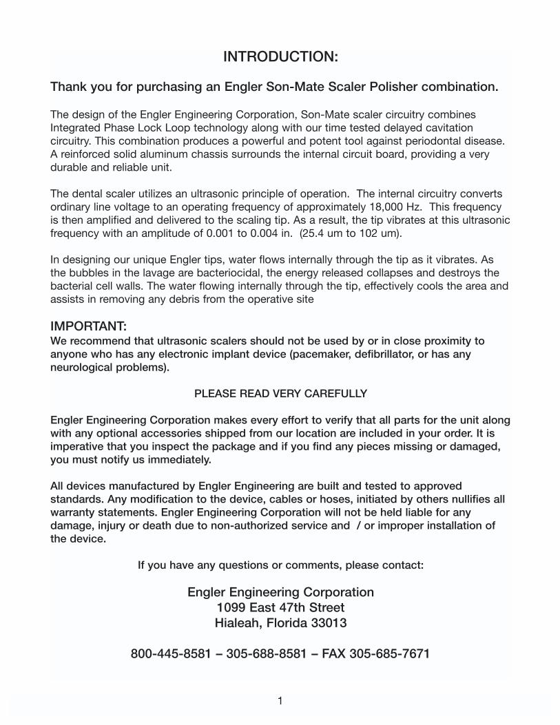
SON MATE ACCESSORIESSon-Mate Accessories
A number of optional handpieces and attachments are available for the Son-Mate unit.1:1 handpieces, reduction handpieces, friction grip or latch type contra angles, prophyangle, 2.35 mm diamond cutting disc, 1.60 mm diamond and carbide bur kits, prophypaste and snap-on rubber cups.AUTOCLAVABLE: All handpieces , metal accessory angles, metal discs and burs areautoclavable. ** Please note Micro motor is not A.C.**
MAINTENANCE FOR THE FRICTION GRIP CONTRA ANGLE (See diagrams on pages 20 and 21)
Part A
1. Hold the contra angle in onehand and the special wrench inthe other.
2. Position the “U” cutout on thewrench which corresponds tothe correct head cap size, over the head cap.Note the wrench only fits on to the flats of thehead cap.
3. Rotate wrench in a clockwise direction until head cap is loose.4. Unscrew the head cap with your fingers, and put aside to be cleaned with alcohol and a
toothbrush.5. Pull the collet assembly from the contra angle’s head.6. Clean the collet assembly with alcohol and a toothbrush then lubricate with mineral oil.7. Put the collet assembly back into the head making sure the long part of the collet
assembly is first into the head, and that the crown on the collet assembly mates with thecrown in the head.
8. Replace head cap, turning counterclockwise secure with finger tight pressure: note donot use the wrench to tighten the cap.
Part B
1. Locate the nut approximately one inch from the head located on the elbow.2. Unscrew counterclockwise, and separate the head from the main body.3. Remove the shaft that is located in either the main body or the head.4. Clean the shaft with alcohol and a toothbrush, then lubricate with a light film of mineral
oil making sure that a drop of oil is placed in the hole that is in the middle of the shaft.Apply a drop of mineral oil on both ends (crowns) for lubrication.
5. Replace the shaft into the main body (short end first).6. Fit the head onto the long end of the shaft, making sure that the teeth on the head aligns
with the teeth of the main body at the correct angle for the desired operation.7. Secure the nut using only finger pressure.
20
P-A3 F.G. Contra angle for handpiece

21

22
23

SADDLE VALVE ASSEMBLYInstallation Instructions:
1. To assemble the saddle valve to existing water source:Place the saddle valve over and around your existing 3/8” copper tubing. Evenly tightenthe securing screws so that the saddle valve is securely fastened onto the copper tubing.
DO NOT OVERTIGHTEN, THIS MAY CAUSE THE COPPER TUBING TO CRIMP ANDREDUCE FLOW.
2. To Mount the Female Quick Disconnect:
YOU HAVE TWO OPTIONS.
Option “A”Take the other end of the 1/4” watertubing that comes from the saddlevalve and connect it to the femalequick disconnect. This is done byplacing the hose coupling nut overthe water tubing and placing thehose into the back of the femalequick disconnect, then tightening thecoupling nut.
Option “B”If you wish, the female quickdisconnect may be mounted directlythrough the sink top or vanity counter. If you choose this way, you must first drill a1/2” diameter hole through the surface in the space desired. (see next page) Thenmount the female quick disconnect and tighten the mounting nut to securely holdit in place. Then proceed to place the hose coupling nut over the 1/4” watertubing. Place this tubing into the back of the female quick disconnect and tightenthe hose coupling nut securely.
3. To Pierce Existing Water Tube:You are now ready to pierce the copper tube. Turn the handle of the saddlevalve ina CLOCKWISE direction until it will go no further. The Saddle valve is now installedand in the OFF position. Turn the handle of the Saddle valve counter-clockwiseuntil resistance is felt. Water is ready to flow into the dental unit. Check for leaks.
4. To Connect the Scaler to the Quick Disconnect:Push the male quick disconnect from the scaler into the female quick disconnectuntil they lock and installation is complete.
24
A-44303 Saddle valve assemblyw/female connector & tubing

Rubber Gasket
Securing screws
3/8” Copper tubing
Securing nut
Hose coupling nut
Mounting nut
Female quickdisconnect
1/4” Tubing
Option A
WALL
Option B
Engler Engineering Corporation will not be held liable for any damage including, but not limitedto leakage caused by improper installation of our products.
25

WATER TANK INSTRUCTIONS:
DIRECTIONS:
1. Remove pump and cap assembly.2. Fill tank with water or medicated solution up to the
“FILL LINE” mark. Do NOT fill beyond this line.3. Replace pump and cap assembly and tighten
securely.4. Pressurize tank by pumping it approximately 10-20
times (depending on the amount of liquid used). Ifa hissing sound is detected, tank is over-pressurized. Stop pumping. Leave tank on a levelsurface until hissing stops. Insert the male quickdisconnect on the end of the waterline from scalerinto female quick disconnect provided on tank.
WATER TANK CARE & MAINTENANCE:
NOTE: A small amount of care will repay in long life and efficient operation.
1. RELEASE AIR PRESSURE by turning knob of pressure relief valve. Pull out fullyand allow air to escape.
2. Loosen cap slowly. Remove pump & cap assembly. Pour out any remainingliquid & rinse all parts thoroughly with clean water.
3. Always store tank empty and with tank cap loose, upside down.
TROUBLESHOOTING:
PROBLEM: TANK FAILS TO PRESSURIZE.
1. Be sure cap is tight.2. Check to see if pressure relief valve is in safety position.3. Remove the pump from the tank. Turn pump handle counterclockwise and lift
handle to unlock. On top of the pump cap there is an opening that says “oilhere”. Place 2 or 3 drops of oil (20 weight, household vegetable oil, etc.) intothe opening. Pump several times to work the oil into the walls of the pump untilit moves freely. Repeat if necessary. Screw the pump back into the tank andresume normal operations. This process should be repeated often dependingon usage, or when pump starts to work harder.
4. Black particles found in water, the pump assembly is deteriorating. Order newpump assembly from Engler Engineering.
Pump assembly has been pre-lubricated...DO NOT TAKE THIS ASSEMBLYAPART TO CLEAN INSIDE PUMP.
26
PT-1 Water Tank

WARNING:
READ AND FOLLOW ALL INSTRUCTIONS.
ALWAYS INSPECT your pump before each use.
ALWAYS RELEASE AIR pressure before removing pump or servicing tank, by pullingpressure relief valve knob out fully.
ALWAYS TIGHTEN CAP securely, a loose cap could be forcibly ejected & cause injury.
DO NOT use mechanical devices to pressurize the tank They can create excessive anddangerous pressure which could cause the tank to explode.
DO NOT STAND over pressurized tank while using it or pumping it
DO NOT USE solutions hotter than 105°F.
D0 NOT damage or alter the functions of the pressure relief valve or plug the pressure reliefvalve hole, as this could cause the tank to explode
DO NOT pressurize the tank until ready for use.
DO NOT lift or carry the tank by waterline, extension rod or pump handle unless it is securelylocked in place.
CARE AND MAINTENANCE OF YOUR PORTABLE WATER TANK
To keep slime from forming inside the tank and eventually getting into the dental unit:
Every two weeks dispose of water in tank. Pour 1/2 cup of bleach and one quart of hot waterinto tank and swirl the liquid thoroughly inside the tank.
DO NOT PLACE pump assembly in tank with Clorox solution as lubrication inside theassembly may react with the mixture.
Dispose of the bleach mixture and rinse the tank out. You can allow the tank to dry overnightor fill it again with distilled water.
Clean the outside of the pump assembly with paper towels and alcohol.
The pump assembly has been pre-lubricated. DO NOT TAKE THIS ASSEMBLY APART.
27

DIAMOND DISC OPERATING INSTRUCTIONS: The diamond disc is an extremely powerful and versatile tool which may be used for dentaland other surgical procedures.
WARNING !!!Keep the cutting disc away from any surface you DO NOT wish to cut. The disc operates ata very high speed and it is extremely sharp. The disc will cut through Skin, Bone, and Toothsurfaces with no resistance. Keep fingers away from disc at all times.
NOTE: To prevent thermal damage to the surface being cut, it is highly recommended thatyou irrigate the area being cut with water during the procedure.
Always wear protective eyeware when using the cutting disc.
1. Place the cutting disc into the straight handpiece. This can be done by performing thefollowing:
A. Hold the straight handpiece in one hand,and rotate the movable collar so that the dot on the collar linesup with the arrow/marker on the straighthandpiece.
B. If there is another tool in the straighthandpiece, remove it at this time
C. Fully insert the shaft of the disc into thechuck of the straight handpiece.
D. Rotate the movable collar so that the doton the collar lines up with the dot on thestraight handpiece.
2. Rotate the selector knob on the front of unit toeither micromotor forward or reverse operation.
Important: Do Not run the Micromotor/Straight Handpiece Assembly without a ProphyAngle, Cutting Disk, Contra Angle or other accessory installed. Doing so could damage theStraight Handpiece and/or Micromotor.
Important: When installing the Cutting Disc or other accessory make sure that the dots lineup EXACTLY, and when securing the Prophy Angle or other accessory make sure that theWhite Dot on the Collar lines up exactly with the White Dot on the Straight Handpiece,otherwise the Straight Handpiece will not operate.
3. Adjust “POWER” control to a medium to high setting.4.To activate, depress footswitch.
28
P-129 Diamond cutting disc 18 MM dia.P-130 Diamond cutting disc 22 MM dia.Both disc’s have a 2.35 mm post diameter

CARE FOR YOUR MAINTENANCE-FREE ANGLE
STERILIZATION PROCEDURES: After each prophy...
A. Remove rubber cup.B. Rinse abrasive paste from head
area with water.C. Thoroughly clean the outside of
angle with disinfectant.D. Autoclave angle - not more than
275°F (135°C)E. After sterilization cycle is
complete, install a newdisposable rubber cup and attach angle to handpiece.You are now ready for your next prophy.
CAUTIONS AND WARNINGS:
A. Do not attempt to disassemble.B. DO NOT SUBMERGE IN LIQUIDS, INCLUDING ULTRASONIC SOLUTIONS.C. Do not heat over 275°F (135°C).D. Use only Engler Care Free Prophy Rubber Cups. Other brands will not properly seal the
angle, causing premature wear and voiding the warranty.E. Use 1 year and dispose of properly.
YOUR CARE-FREE ANGLE IS WARRANTED AGAINST DEFECTS IN MATERIAL ANDWORKMANSHIP FOR 6 MONTHS. A COPY OF OUR INVOICE OR PICKING TICKET WILLBE REQUIRED AS PROOF OF PURCHASE.
WARRANTY IS VOID IF:
A. Engler Care-Free rubber cups are not used exclusively.B. Sterilization procedure is not followed properly.C. The angle has been submerged in any liquid.D. The angle has been damaged or abused.E. Damaged due to use at high speed.
29
P-MF Maintenance free prophy angleP-106 screw on rubber cups 144/pkt
P-MF
P-106

30
Optional Son-Mate Accessories
P-131 Carbide Burs - Kit of 6P-132 Diamond Burs - Kit of 7
P112 Polishing paste (8 oz. jar)
P-105 Snap on rubber cups 144/pktP-110 polishing paste (200 cups)
133-1199 Sonus feline catheter
If you have any questions or concerns, please call us.ENGLER ENGINEERING CORP
800-445-8581.
Optional Oiling AccessorySpray Lubricant with E-Type Nozzle
for all Engler Polishing StraightHandpieces
8.8 Oz / 355 ML
To Order call:
At 1-800-445-8581or 305-688-8581
8.8 Oz. / 355 ML # P-02

WARRANTY INFORMATION
It is imperative that when calling Engler Engineering regarding the operation of yourunit, that you have the serial number available for quick reference.
The Son-Mate, scaler polisher combination, with attachments, is warranted to befree from material and manufacturing defects to the original consumer / purchaser for aperiod as specified below.
The Son-Mate control box is warranted for a period of six (6) years from date of purchase.The scaler handpiece is warranted for a period of two (2) years from date of purchase.The Micromotor is warranted for a period of one (1) year from date of purchase.The polishing straight handpiece is warranted for a period of one year from date of purchase.Stacks (transducer) are warranted for a period of six (6) months from date of purchase.Scaling tips are warranted for a period of thirty (30) days from date of purchase. Prophy and Contra angles, burs and cutting discs are warranted for a period of thirty (30)days from date of purchase.
All warranties are void if the items have been damaged due to negligence, improper use,failure to lubricate, removed parts, or opening the control unit.
PLEASE NOTE:
Whenever returning any products for evaluation and / or repair, we strongly suggest yousend in the complete unit with all attachments so that a correct evaluation can be made. Engler Engineering Corp., has been in business since 1964, in Hialeah, Florida, building andmaintaining dental units and parts for not only our ultrasonic scalers, polishers, andanesthesia machine, but for many others on the market today. As a leader in the field, wewould appreciate a minute of your time to let us know how we can better serve you.
You can mail all comments, suggestions and questions to us at the following address andnumber:
Engler Engineering Corp.1099 East 47 StreetHialeah, FL 33013
If you wish to fax to us, please use 305-685-7671. For your convenience, the following names are listed for your correspondence:
President Eva EnglerVP Sales & Marketing Steven MenagedOperations Manager Joel KatzCustomer Service Raya EnglerCust. Service/Repair Harvey Meinstein
31

RETURN FOR EVALUATION / REPAIR FORM
PLEASE PHOTOCOPY AND INCLUDE A COMPLETED COPY WHENEVER SENDINGUNITS IN TO US FOR EVALUATION AND / OR REPAIR.
CLINIC PHONE NUMBER: ___________________________FAX #___________________________
CLINIC NAME: _____________________________________________________________________
Contact person: ____________________________________________________________________
Shipping Address: __________________________________________________________________
City: ___________________________ State: ___________________ Zip: _______
Item being sent: ____________________________________________________________________
Please describe what is happening or why you are sending in this unit:____________________________________________________________________________________
____________________________________________________________________________________
____________________________________________________________________________________
When returning items to us, we would prefer you send the complete unit so that a properevaluation can be made.
It is suggested that you ship all returns to us by Federal Express, UPS or DHL. If using USMail, it is suggested that you track and insure the package.
Address all returns as follows:
ENGLER ENGINEERING CORP.REPAIR DEPARTMENT1099 EAST 47 STREET
HIALEAH, FL 33013
33
If you have any questions or concerns, please call us.ENGLER ENGINEERING CORP 800-445-8581.

34
Lifetime Loaner Program Form

Notes:
35