Embed Size (px)
Citation preview
Introduction 4
Instrument Cluster 10
Warning lights and chimes 10Gauges 14
Entertainment Systems 17
AM/FM stereo with CD 17AM/FM stereo with in-dash six CD 20Family entertainment system 25
Climate Controls 40
Manual heating and air conditioning 40Automatic temperature control 42Rear window defroster 47
Lights 48
Headlamps 48Turn signal control 52Bulb replacement 52
Driver Controls 58
Windshield wiper/washer control 58Steering wheel adjustment 59Power windows 61Mirrors 64Speed control 65Moon roof 69Message center 74
Locks and Security 84
Keys 84Locks 84Anti-theft system 96
Table of Contents
1
2006 Five Hundred (500)Owners Guide (post-2002-fmt)USA (fus)
Seating and Safety Restraints 101
Seating 101Safety restraints 109Airbags 123Child restraints 137
Tires, Wheels and Loading 149
Tire Information 149Tire Inflation 151Vehicle loading 163Trailer towing 169Recreational towing 171
Driving 172
Starting 172Brakes 175Traction control 178Transmission operation 179
Roadside Emergencies 192
Getting roadside assistance 192Hazard flasher switch 194Fuel pump shut-off switch 194Fuses and relays 195Changing tires 201Lug Nut Torque 208Jump starting 208Wrecker towing 214
Customer Assistance 216
Reporting safety defects (U.S. only) 222
Cleaning 223
Table of Contents
2
2006 Five Hundred (500)Owners Guide (post-2002-fmt)USA (fus)

Maintenance and Specifications 230
Engine compartment 232Engine oil 234Battery 237Engine Coolant 239Fuel information 245Part numbers 259Refill capacities 260Lubricant specifications 262Engine data 264
Accessories 268
Index 271
All rights reserved. Reproduction by any means, electronic or mechanicalincluding photocopying, recording or by any information storage and retrievalsystem or translation in whole or part is not permitted without writtenauthorization from Ford Motor Company. Ford may change the contents withoutnotice and without incurring obligation.
Copyright © 2006 Ford Motor Company
Table of Contents
3
2006 Five Hundred (500)Owners Guide (post-2002-fmt)USA (fus)
CALIFORNIA Proposition 65 Warning
WARNING: Engine exhaust, some of its constituents, andcertain vehicle components contain or emit chemicals known to
the State of California to cause cancer and birth defects or otherreproductive harm. In addition, certain fluids contained in vehicles andcertain products of component wear contain or emit chemicals knownto the State of California to cause cancer and birth defects or otherreproductive harm.
CONGRATULATIONSCongratulations on acquiring your new Ford. Please take the time to getwell acquainted with your vehicle by reading this handbook. The moreyou know and understand about your vehicle, the greater the safety andpleasure you will derive from driving it.
For more information on Ford Motor Company and its products visit thefollowing website:
• In the United States: www.ford.com
• In Canada: www.ford.ca
• In Australia: www.ford.com.au
• In Mexico: www.ford.com.mx
Additional owner information is given in separate publications.
This Owner’s Guide describes every option and model variant availableand therefore some of the items covered may not apply to yourparticular vehicle. Furthermore, due to printing cycles it may describeoptions before they are generally available.
Remember to pass on this Owner’s Guide when reselling the vehicle. Itis an integral part of the vehicle.
Fuel pump shut-off switch: In the event of an accident thesafety switch will automatically cut off the fuel supply to the
engine. The switch can also be activated through sudden vibration (e.g.collision when parking). To reset the switch, refer to the Fuel pumpshut-off switch in the Roadside Emergencies chapter.
2006 Five Hundred (500)Owners Guide (post-2002-fmt)USA (fus)
Introduction
4
SAFETY AND ENVIRONMENT PROTECTION
Warning symbols in this guide
How can you reduce the risk of personal injury to yourself or others? Inthis guide, answers to such questions are contained in commentshighlighted by the warning triangle symbol. These comments should beread and observed.
Warning symbols on your vehicle
When you see this symbol, it isimperative that you consult therelevant section of this guide beforetouching or attempting adjustmentof any kind.
Protecting the environmentWe must all play our part inprotecting the environment. Correctvehicle usage and the authorizeddisposal of waste, cleaning andlubrication materials are significantsteps towards this aim. Information in this respect is highlighted in thisguide with the tree symbol.
BREAKING-IN YOUR VEHICLEYour vehicle does not need an extensive break-in. Try not to drivecontinuously at the same speed for the first 1,000 miles (1,600 km) ofnew vehicle operation. Vary your speed frequently in order to give themoving parts a chance to break in.
Drive your new vehicle at least 500 miles (800 km) before towing atrailer. For more detailed information about towing a trailer, refer toTrailer towing in the Tires, Wheels and Loading chapter.
Do not add friction modifier compounds or special break-in oils sincethese additives may prevent piston ring seating. See Engine oil in theMaintenance and Specifications chapter for more information on oilusage.
2006 Five Hundred (500)Owners Guide (post-2002-fmt)USA (fus)
Introduction
5
SPECIAL NOTICES
New Vehicle Limited WarrantyFor a detailed description of what is covered and what is not covered byyour vehicle’s New Vehicle Limited Warranty, refer to the WarrantyGuide that is provided to you along with your Owner’s Guide.
Service Data RecordingService data recorders in your vehicle are capable of collecting andstoring diagnostic information about your vehicle. This potentiallyincludes information about the performance or status of various systemsand modules in the vehicle, such as engine, throttle, steering or brakesystems. In order to properly diagnose and service your vehicle, FordMotor Company, Ford of Canada, and service and repair facilities mayaccess vehicle diagnostic information through a direct connection to yourvehicle when diagnosing or servicing your vehicle.
Event Data RecordingOther modules in your vehicle — event data recorders — are capable ofcollecting and storing data during a crash or near crash event. Therecorded information may assist in the investigation of such an event.The modules may record information about both the vehicle and theoccupants, potentially including information such as:
• how various systems in your vehicle were operating;
• whether or not the driver and passenger seatbelts were buckled;
• how far (if at all) the driver was depressing the accelerator and/or thebrake pedal;
• how fast the vehicle was traveling; and
• where the driver was positioning the steering wheel.
To access this information, special equipment must be directly connectedto the recording modules. Ford Motor Company and Ford of Canada donot access event data recorder information without obtaining consent,unless pursuant to court order or where required by law enforcement,other government authorities or other third parties acting with lawfulauthority. Other parties may seek to access the informationindependently of Ford Motor Company and Ford of Canada.
2006 Five Hundred (500)Owners Guide (post-2002-fmt)USA (fus)
Introduction
6
Special instructionsFor your added safety, your vehicle is fitted with sophisticated electroniccontrols.
Please read the section Supplemental restraint system (SRS)in the Seating and Safety Restraints chapter. Failure to follow
the specific warnings and instructions could result in personal injury.
Front seat mounted rear-facing child or infant seats shouldNEVER be placed in front of an active passenger airbag.
Cell phone useThe use of Mobile Communications Equipment has become increasinglyimportant in the conduct of business and personal affairs. However,drivers must not compromise their own or others’ safety when usingsuch equipment. Mobile Communications can enhance personal safetyand security when appropriately used, particularly in emergencysituations. Safety must be paramount when using mobile communicationsequipment to avoid negating these benefits.
Mobile Communication Equipment includes, but is not limited to cellularphones, pagers, portable email devices, in-vehicle communicationssystems, telematics devices and portable two-way radios.
A driver’s first responsibility is the safe operation of the vehicle.The most important thing you can do to prevent a crash is to
avoid distractions and pay attention to the road. Wait until it is safe tooperate Mobile Communications Equipment.
Middle East/North Africa vehicle specific informationFor your particular global region, your vehicle may be equipped withfeatures and options that are different from the ones that are describedin this Owner’s Guide; therefore, a supplement has been supplied thatcomplements this book. By referring to the pages in the providedsupplement, you can properly identify those features, recommendationsand specifications that are unique to your vehicle. Refer to thisOwner’s Guide for all other required information and warnings.
2006 Five Hundred (500)Owners Guide (post-2002-fmt)USA (fus)
Introduction
7
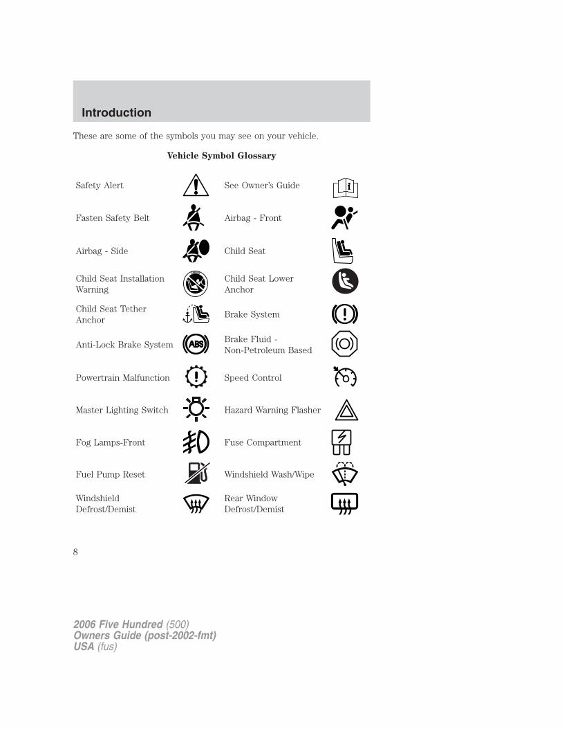
These are some of the symbols you may see on your vehicle.
Vehicle Symbol Glossary
Safety Alert See Owner’s Guide
Fasten Safety Belt Airbag - Front
Airbag - Side Child Seat
Child Seat InstallationWarning
Child Seat LowerAnchor
Child Seat TetherAnchor
Brake System
Anti-Lock Brake SystemBrake Fluid -Non-Petroleum Based
Powertrain Malfunction Speed Control
Master Lighting Switch Hazard Warning Flasher
Fog Lamps-Front Fuse Compartment
Fuel Pump Reset Windshield Wash/Wipe
WindshieldDefrost/Demist
Rear WindowDefrost/Demist
2006 Five Hundred (500)Owners Guide (post-2002-fmt)USA (fus)
Introduction
8
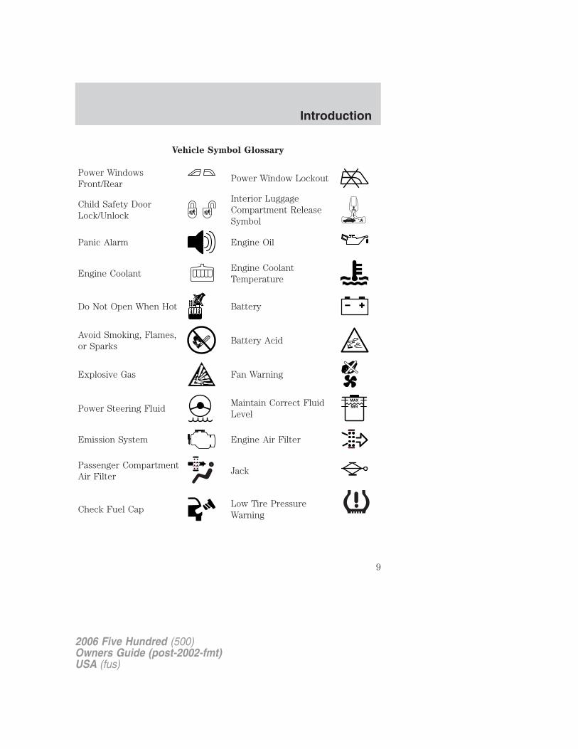
Vehicle Symbol Glossary
Power WindowsFront/Rear
Power Window Lockout
Child Safety DoorLock/Unlock
Interior LuggageCompartment ReleaseSymbol
Panic Alarm Engine Oil
Engine CoolantEngine CoolantTemperature
Do Not Open When Hot Battery
Avoid Smoking, Flames,or Sparks
Battery Acid
Explosive Gas Fan Warning
Power Steering FluidMaintain Correct FluidLevel
MAX
MIN
Emission System Engine Air Filter
Passenger CompartmentAir Filter
Jack
Check Fuel CapLow Tire PressureWarning
2006 Five Hundred (500)Owners Guide (post-2002-fmt)USA (fus)
Introduction
9
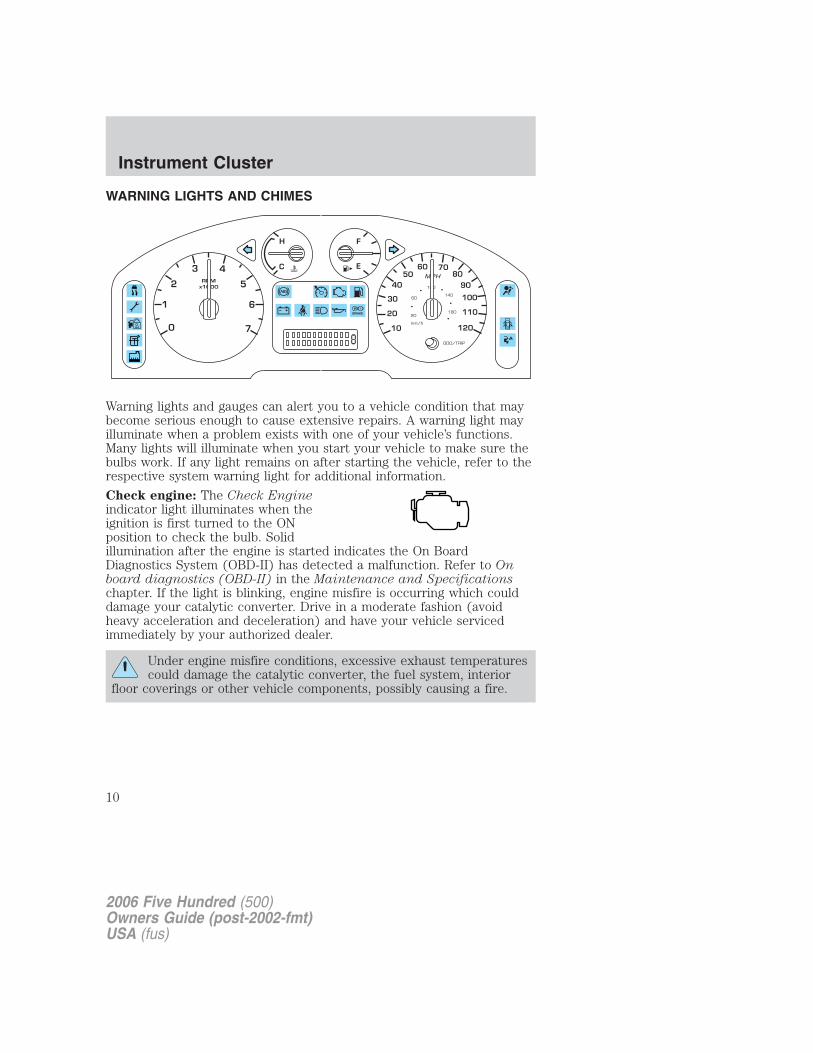
WARNING LIGHTS AND CHIMES
Warning lights and gauges can alert you to a vehicle condition that maybecome serious enough to cause extensive repairs. A warning light mayilluminate when a problem exists with one of your vehicle’s functions.Many lights will illuminate when you start your vehicle to make sure thebulbs work. If any light remains on after starting the vehicle, refer to therespective system warning light for additional information.
Check engine: The Check Engineindicator light illuminates when theignition is first turned to the ONposition to check the bulb. Solidillumination after the engine is started indicates the On BoardDiagnostics System (OBD-II) has detected a malfunction. Refer to Onboard diagnostics (OBD-II) in the Maintenance and Specificationschapter. If the light is blinking, engine misfire is occurring which coulddamage your catalytic converter. Drive in a moderate fashion (avoidheavy acceleration and deceleration) and have your vehicle servicedimmediately by your authorized dealer.
Under engine misfire conditions, excessive exhaust temperaturescould damage the catalytic converter, the fuel system, interior
floor coverings or other vehicle components, possibly causing a fire.
2006 Five Hundred (500)Owners Guide (post-2002-fmt)USA (fus)
Instrument Cluster
10
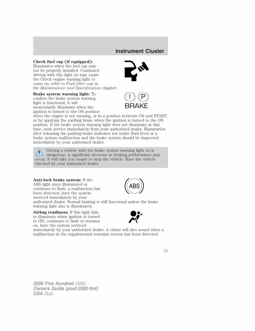
Check fuel cap (if equipped):Illuminates when the fuel cap maynot be properly installed. Continueddriving with this light on may causethe Check engine warning light tocome on, refer to Fuel filler cap inthe Maintenance and Specification chapter.
Brake system warning light: Toconfirm the brake system warninglight is functional, it willmomentarily illuminate when theignition is turned to the ON positionwhen the engine is not running, or in a position between ON and START,or by applying the parking brake when the ignition is turned to the ONposition. If the brake system warning light does not illuminate at thistime, seek service immediately from your authorized dealer. Illuminationafter releasing the parking brake indicates low brake fluid level or abrake system malfunction and the brake system should be inspectedimmediately by your authorized dealer.
Driving a vehicle with the brake system warning light on isdangerous. A significant decrease in braking performance may
occur. It will take you longer to stop the vehicle. Have the vehiclechecked by your authorized dealer.
Anti-lock brake system: If theABS light stays illuminated orcontinues to flash, a malfunction hasbeen detected, have the systemserviced immediately by yourauthorized dealer. Normal braking is still functional unless the brakewarning light also is illuminated.
Airbag readiness: If this light failsto illuminate when ignition is turnedto ON, continues to flash or remainson, have the system servicedimmediately by your authorized dealer. A chime will also sound when amalfunction in the supplemental restraint system has been detected.
P!BRAKE
ABS
2006 Five Hundred (500)Owners Guide (post-2002-fmt)USA (fus)
Instrument Cluster
11
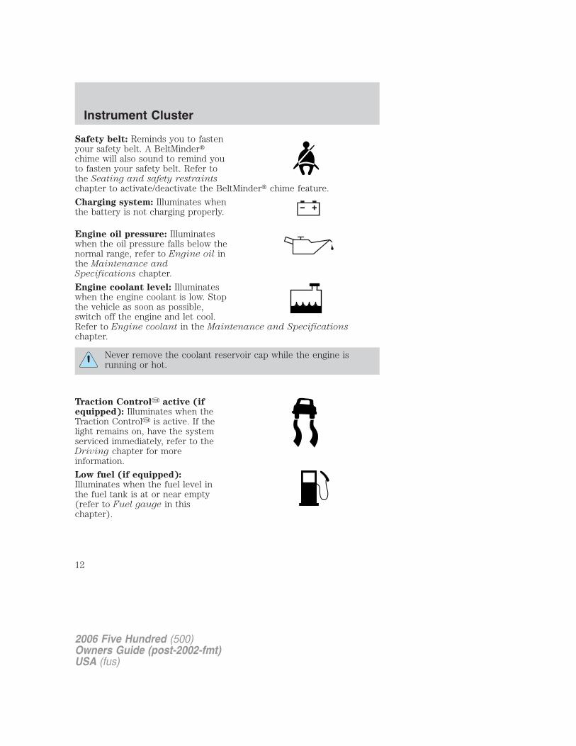
Safety belt: Reminds you to fastenyour safety belt. A BeltMinder�chime will also sound to remind youto fasten your safety belt. Refer tothe Seating and safety restraintschapter to activate/deactivate the BeltMinder� chime feature.
Charging system: Illuminates whenthe battery is not charging properly.
Engine oil pressure: Illuminateswhen the oil pressure falls below thenormal range, refer to Engine oil inthe Maintenance andSpecifications chapter.
Engine coolant level: Illuminateswhen the engine coolant is low. Stopthe vehicle as soon as possible,switch off the engine and let cool.Refer to Engine coolant in the Maintenance and Specificationschapter.
Never remove the coolant reservoir cap while the engine isrunning or hot.
Traction Control� active (ifequipped): Illuminates when theTraction Control� is active. If thelight remains on, have the systemserviced immediately, refer to theDriving chapter for moreinformation.
Low fuel (if equipped):Illuminates when the fuel level inthe fuel tank is at or near empty(refer to Fuel gauge in thischapter).
2006 Five Hundred (500)Owners Guide (post-2002-fmt)USA (fus)
Instrument Cluster
12
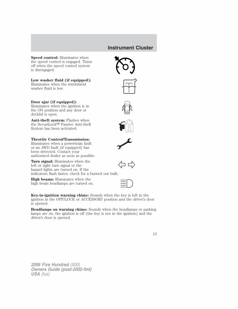
Speed control: Illuminates whenthe speed control is engaged. Turnsoff when the speed control systemis disengaged.
Low washer fluid (if equipped):Illuminates when the windshieldwasher fluid is low.
Door ajar (if equipped):Illuminates when the ignition is inthe ON position and any door ordecklid is open.
Anti-theft system: Flashes whenthe SecuriLock� Passive Anti-theftSystem has been activated.
Throttle Control/Transmission:Illuminates when a powertrain faultor an AWD fault (if equipped) hasbeen detected. Contact yourauthorized dealer as soon as possible.
Turn signal: Illuminates when theleft or right turn signal or thehazard lights are turned on. If theindicators flash faster, check for a burned out bulb.
High beams: Illuminates when thehigh beam headlamps are turned on.
Key-in-ignition warning chime: Sounds when the key is left in theignition in the OFF/LOCK or ACCESSORY position and the driver’s dooris opened.
Headlamps on warning chime: Sounds when the headlamps or parkinglamps are on, the ignition is off (the key is not in the ignition) and thedriver’s door is opened.
2006 Five Hundred (500)Owners Guide (post-2002-fmt)USA (fus)
Instrument Cluster
13
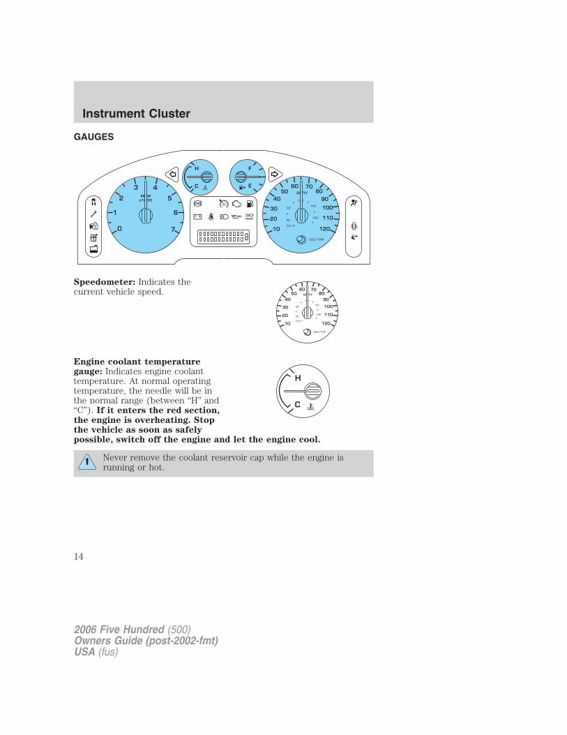
GAUGES
Speedometer: Indicates thecurrent vehicle speed.
Engine coolant temperaturegauge: Indicates engine coolanttemperature. At normal operatingtemperature, the needle will be inthe normal range (between “H” and“C”). If it enters the red section,the engine is overheating. Stopthe vehicle as soon as safelypossible, switch off the engine and let the engine cool.
Never remove the coolant reservoir cap while the engine isrunning or hot.
2006 Five Hundred (500)Owners Guide (post-2002-fmt)USA (fus)
Instrument Cluster
14
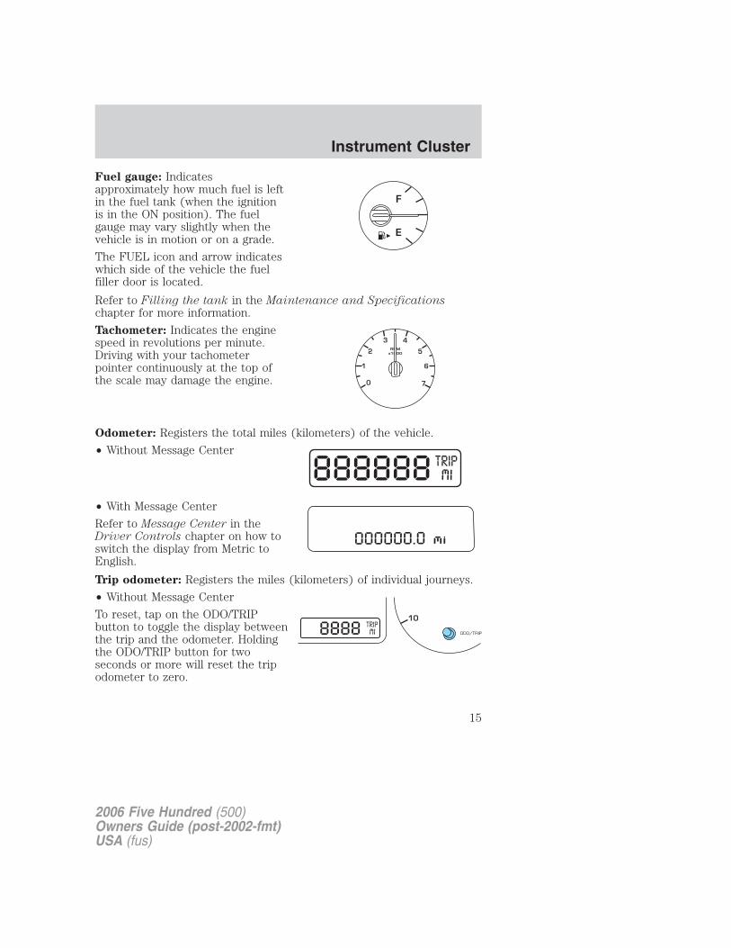
Fuel gauge: Indicatesapproximately how much fuel is leftin the fuel tank (when the ignitionis in the ON position). The fuelgauge may vary slightly when thevehicle is in motion or on a grade.
The FUEL icon and arrow indicateswhich side of the vehicle the fuelfiller door is located.
Refer to Filling the tank in the Maintenance and Specificationschapter for more information.
Tachometer: Indicates the enginespeed in revolutions per minute.Driving with your tachometerpointer continuously at the top ofthe scale may damage the engine.
Odometer: Registers the total miles (kilometers) of the vehicle.
• Without Message Center
• With Message Center
Refer to Message Center in theDriver Controls chapter on how toswitch the display from Metric toEnglish.
Trip odometer: Registers the miles (kilometers) of individual journeys.
• Without Message Center
To reset, tap on the ODO/TRIPbutton to toggle the display betweenthe trip and the odometer. Holdingthe ODO/TRIP button for twoseconds or more will reset the tripodometer to zero.
2006 Five Hundred (500)Owners Guide (post-2002-fmt)USA (fus)
Instrument Cluster
15
• With Message Center
To reset with the ODO/TRIP button:
• Tap on the button to toggle the display between the trip and theodometer. Holding the ODO/TRIP button for two seconds or more willreset the trip odometer to zero.
To reset with the message centerbuttons:
• Select the TRIP function from theINFO menu. Depressing theRESET control for approximatelyone second will reset the tripodometer to zero.
Note: The following is for vehicles without a message center. Forvehicles with a message center, refer to Message Center in the DriverControls chapter.
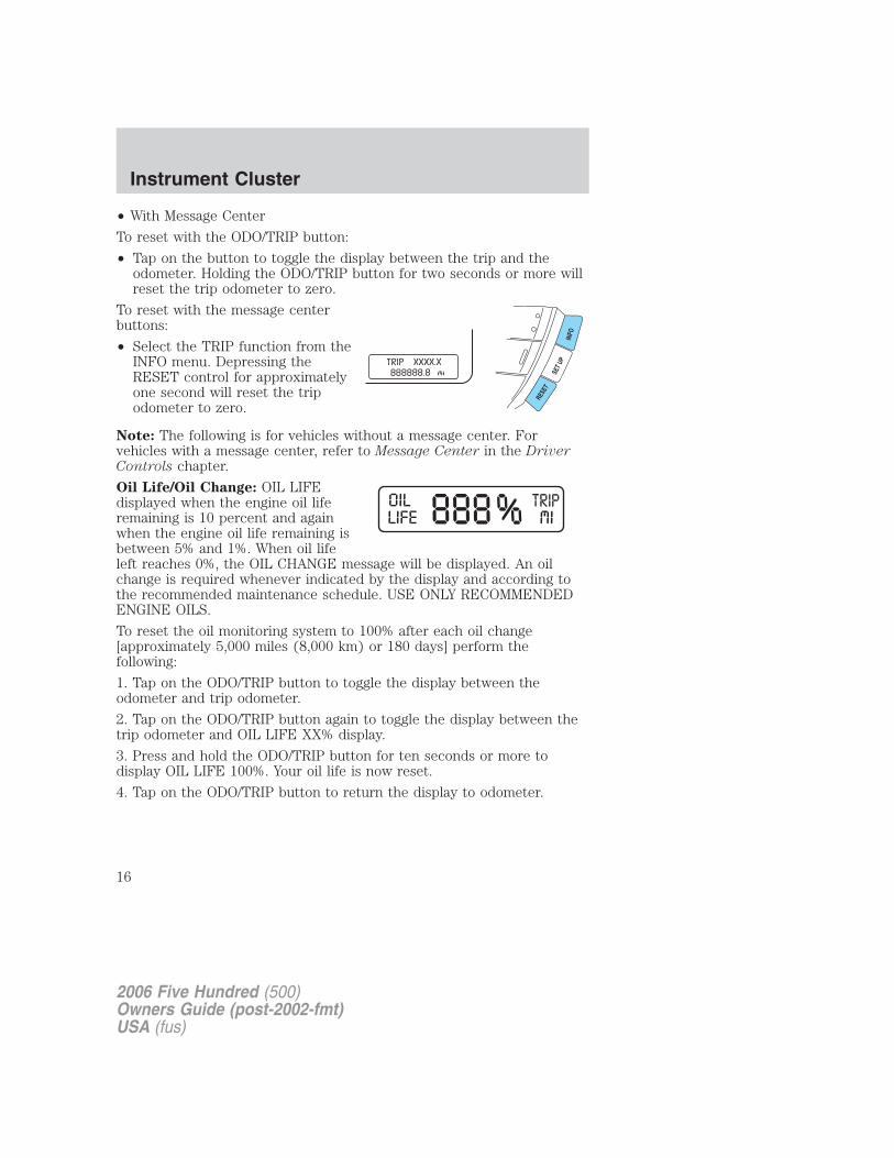
Oil Life/Oil Change: OIL LIFEdisplayed when the engine oil liferemaining is 10 percent and againwhen the engine oil life remaining isbetween 5% and 1%. When oil lifeleft reaches 0%, the OIL CHANGE message will be displayed. An oilchange is required whenever indicated by the display and according tothe recommended maintenance schedule. USE ONLY RECOMMENDEDENGINE OILS.
To reset the oil monitoring system to 100% after each oil change[approximately 5,000 miles (8,000 km) or 180 days] perform thefollowing:
1. Tap on the ODO/TRIP button to toggle the display between theodometer and trip odometer.
2. Tap on the ODO/TRIP button again to toggle the display between thetrip odometer and OIL LIFE XX% display.
3. Press and hold the ODO/TRIP button for ten seconds or more todisplay OIL LIFE 100%. Your oil life is now reset.
4. Tap on the ODO/TRIP button to return the display to odometer.
2006 Five Hundred (500)Owners Guide (post-2002-fmt)USA (fus)
Instrument Cluster
16
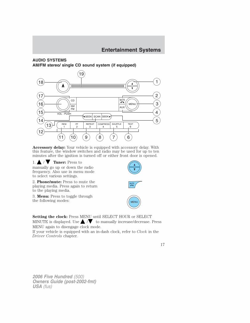
AUDIO SYSTEMSAM/FM stereo/ single CD sound system (if equipped)
Accessory delay: Your vehicle is equipped with accessory delay. Withthis feature, the window switches and radio may be used for up to tenminutes after the ignition is turned off or either front door is opened.
1. / Tuner: Press tomanually go up or down the radiofrequency. Also use in menu modeto select various settings.
2. Phone/mute: Press to mute theplaying media. Press again to returnto the playing media.
3. Menu: Press to toggle throughthe following modes:
Setting the clock: Press MENU until SELECT HOUR or SELECTMINUTE is displayed. Use / to manually increase/decrease. PressMENU again to disengage clock mode.If your vehicle is equipped with an in-dash clock, refer to Clock in theDriver Controls chapter.
1211 10 9 8 7
4
1
2
3
6
14
15
16
17
18
19
513 COMPRESS
2006 Five Hundred (500)Owners Guide (post-2002-fmt)USA (fus)
Entertainment Systems
17
Autoset: Allows you to set the strongest local radio stations withoutlosing your original manually set preset stations for AM/FM1/FM2 . Press
MENU to access. Use / / SEEK to set.
When the six strongest stations are filled, the station stored in preset 1will begin playing. If there are less than six strong stations, the systemwill store the last one in the remaining presets.
Bass: Press to adjust the bass setting. Use / / SEEK .
Treble: Press to adjust the treble setting. Use / / SEEK .
Balance: Press to adjust the audio between the left and right speakers.
Use / / SEEK .
Fade: Press to adjust the audio between the front and rear speakers.
Use / / SEEK .
Speed sensitive volume (if equipped): Radio volume automaticallychanges slightly with vehicle speed to compensate for road and wind
noise. Press MENU to access and use / / SEEK to adjust.
Recommended level is 1–3. Level 0 turns the feature off and level 7 isthe maximum setting.
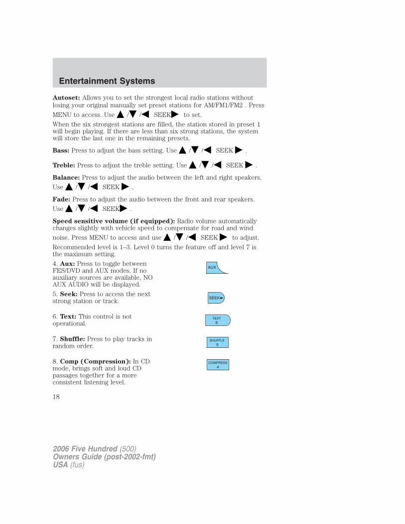
4. Aux: Press to toggle betweenFES/DVD and AUX modes. If noauxiliary sources are available, NOAUX AUDIO will be displayed.
5. Seek: Press to access the nextstrong station or track.
6. Text: This control is notoperational.
7. Shuffle: Press to play tracks inrandom order.
8. Comp (Compression): In CDmode, brings soft and loud CDpassages together for a moreconsistent listening level.
2006 Five Hundred (500)Owners Guide (post-2002-fmt)USA (fus)
Entertainment Systems
18
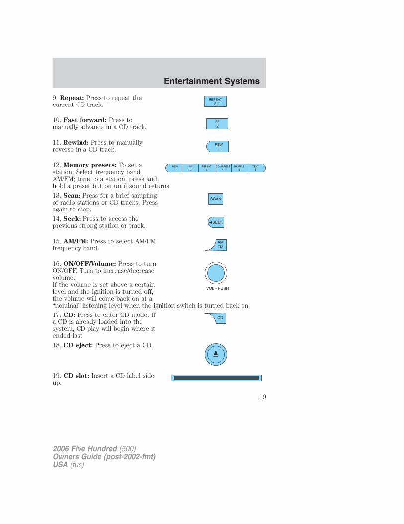
9. Repeat: Press to repeat thecurrent CD track.
10. Fast forward: Press tomanually advance in a CD track.
11. Rewind: Press to manuallyreverse in a CD track.
12. Memory presets: To set astation: Select frequency bandAM/FM; tune to a station, press andhold a preset button until sound returns.
13. Scan: Press for a brief samplingof radio stations or CD tracks. Pressagain to stop.
14. Seek: Press to access theprevious strong station or track.
15. AM/FM: Press to select AM/FMfrequency band.
16. ON/OFF/Volume: Press to turnON/OFF. Turn to increase/decreasevolume.If the volume is set above a certainlevel and the ignition is turned off,the volume will come back on at a“nominal” listening level when the ignition switch is turned back on.
17. CD: Press to enter CD mode. Ifa CD is already loaded into thesystem, CD play will begin where itended last.
18. CD eject: Press to eject a CD.
19. CD slot: Insert a CD label sideup.
2006 Five Hundred (500)Owners Guide (post-2002-fmt)USA (fus)
Entertainment Systems
19
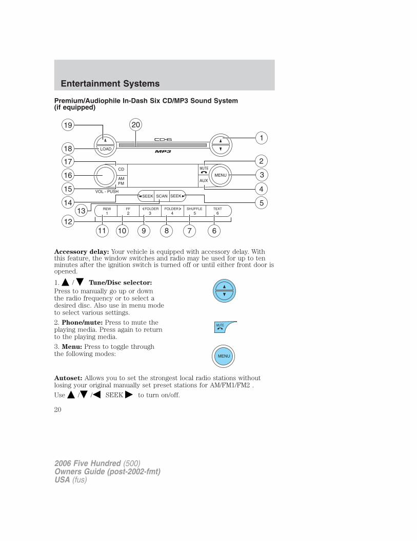
Premium/Audiophile In-Dash Six CD/MP3 Sound System(if equipped)
Accessory delay: Your vehicle is equipped with accessory delay. Withthis feature, the window switches and radio may be used for up to tenminutes after the ignition switch is turned off or until either front door isopened.
1. / Tune/Disc selector:
Press to manually go up or downthe radio frequency or to select adesired disc. Also use in menu modeto select various settings.
2. Phone/mute: Press to mute theplaying media. Press again to returnto the playing media.
3. Menu: Press to toggle throughthe following modes:
Autoset: Allows you to set the strongest local radio stations withoutlosing your original manually set preset stations for AM/FM1/FM2 .
Use / / SEEK to turn on/off.
2006 Five Hundred (500)Owners Guide (post-2002-fmt)USA (fus)
Entertainment Systems
20
When the six strongest stations are filled, the station stored in preset 1will begin playing. If there are less than six strong stations, the systemwill store the last one in the remaining presets.
Bass: Press to adjust the bass setting. Use / / SEEK .
Treble: Press to adjust the treble setting. Use / / SEEK .
Balance: Press to adjust the audio between the left and right speakers.Use / / SEEK .
Fade: Press to adjust the audio between the front and rear speakers.
Use / / SEEK .
Occupancy mode: (Available on Audiophile radios only):
Use / / SEEK select and optimize sound for ALL SEATS,
DRIVERS SEAT or REAR SEATS.
Speed sensitive volume: Radio volume automatically changes slightlywith vehicle speed to compensate for road and wind noise.
Use / / SEEK to adjust. Recommended level is 1–3. Level 0
turns the feature off and level 7 is the maximum setting.
Setting the clock: Press until SELECT HOUR or SELECT MINS is
displayed. Press / / SEEK to adjust the hours/minutes.
If your vehicle is equipped with an in-dash clock, refer to “Setting theclock” in the Driver Controls chapter.
Track/Folder Mode: Available only on MP3 discs in CD mode. In TrackMode, pressing SEEK will scroll through all tracks on the disc.
In Folder mode, pressing SEEK will scroll only through trackswithin the selected folder.
Compression: Available only in CD mode, brings soft and loud CDpassages together for a more consistent listening level.
Repeat: Available only in CD mode. Press to repeat the current CDtrack.
RDS (Available on Audiophile radios only): Allows you to searchRDS-equipped stations for a certain category of music format: Classic,Country, Info, Jazz/RB, Religious, Rock, Soft, Top 40. RDS (only availablein FM mode) must be activated to access Find and Show functions.
2006 Five Hundred (500)Owners Guide (post-2002-fmt)USA (fus)
Entertainment Systems
21
To activate, press and hold MENU until RDS (ON/OFF) appears in thedisplay. Press MENU repeatedly to scroll through Find, Show and RDS.
Use / / SEEK to toggle RDS ON/OFF. When RDS is Off, you
will not be able to access Find and Show functions.
Find: Allows you to search RDS-equipped stations for the desired musiccategory. Use / to find the desired program type, then use
SEEK or SCAN to begin the search.
Show: Allows you to display the name of the radio station or program
type. Use / / SEEK to show type, name or none.
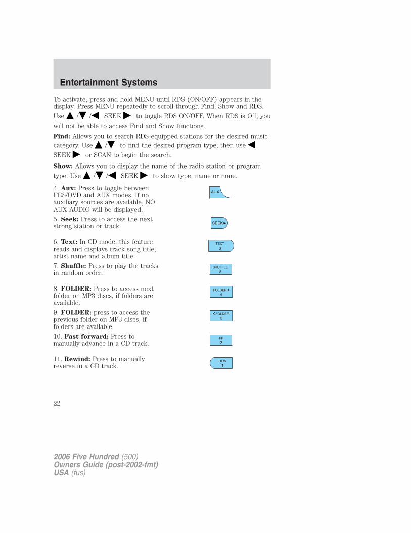
4. Aux: Press to toggle betweenFES/DVD and AUX modes. If noauxiliary sources are available, NOAUX AUDIO will be displayed.
5. Seek: Press to access the nextstrong station or track.
6. Text: In CD mode, this featurereads and displays track song title,artist name and album title.
7. Shuffle: Press to play the tracksin random order.
8. FOLDER: Press to access nextfolder on MP3 discs, if folders areavailable.
9. FOLDER: press to access theprevious folder on MP3 discs, iffolders are available.
10. Fast forward: Press tomanually advance in a CD track.
11. Rewind: Press to manuallyreverse in a CD track.
2006 Five Hundred (500)Owners Guide (post-2002-fmt)USA (fus)
Entertainment Systems
22
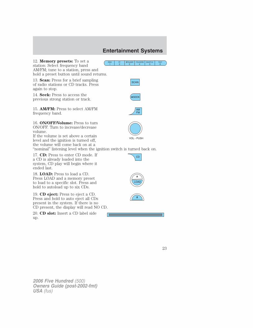
12. Memory presets: To set astation: Select frequency bandAM/FM; tune to a station, press andhold a preset button until sound returns.
13. Scan: Press for a brief samplingof radio stations or CD tracks. Pressagain to stop.
14. Seek: Press to access theprevious strong station or track.
15. AM/FM: Press to select AM/FMfrequency band.
16. ON/OFF/Volume: Press to turnON/OFF. Turn to increase/decreasevolume.If the volume is set above a certainlevel and the ignition is turned off,the volume will come back on at a“nominal” listening level when the ignition switch is turned back on.
17. CD: Press to enter CD mode. Ifa CD is already loaded into thesystem, CD play will begin where itended last.
18. LOAD: Press to load a CD.Press LOAD and a memory presetto load to a specific slot. Press andhold to autoload up to six CDs.
19. CD eject: Press to eject a CD.Press and hold to auto eject all CDspresent in the system. If there is noCD present, the display will read NO CD.
20. CD slot: Insert a CD label sideup.
2006 Five Hundred (500)Owners Guide (post-2002-fmt)USA (fus)
Entertainment Systems
23
GENERAL AUDIO INFORMATIONRadio frequencies:
AM and FM frequencies are established by the Federal CommunicationsCommission (FCC) and the Canadian Radio and TelecommunicationsCommission (CRTC). Those frequencies are:
AM: 530, 540–1700, 1710 kHz
FM: 87.7, 87.9–107.7, 107.9 MHz
Radio reception factors:
There are three factors that can affect radio reception:
• Distance/strength: The further you travel from an FM station, theweaker the signal and the weaker the reception.
• Terrain: Hills, mountains, tall buildings, power lines, electric fences,traffic lights and thunderstorms can interfere with your reception.
• Station overload: When you pass a broadcast tower, a stronger signalmay overtake a weaker one and play while the weak station frequencyis displayed.
CD/CD player care
Do:
• Handle discs by their edges only. Never touch the playing surface.
• Inspect discs before playing. Clean only with an approved CD cleanerand wipe from the center out.
Don’t:
• Expose discs to direct sunlight or heat sources for extended periodsof time.
• Clean using a circular motion.
CD units are designed to play commercially pressed 4.75 in (12cm) audio compact discs only. Due to technical incompatibility,certain recordable and re-recordable compact discs may notfunction correctly when used in Ford CD players. Irregularshaped CDs, CDs with a scratch protection film attached, and CDswith homemade paper (adhesive) labels should not be insertedinto the CD player. The label may peel and cause the CD tobecome jammed. It is recommended that homemade CDs beidentified with permanent felt tip marker rather than adhesivelabels. Ballpoint pens may damage CDs. Please contact yourauthorized dealer for further information.
2006 Five Hundred (500)Owners Guide (post-2002-fmt)USA (fus)
Entertainment Systems
24
Audio system warranty and service
Refer to the Warranty Guide for audio system warranty information. Ifservice is necessary, see your dealer or qualified technician.
Navigation system (if equipped)Your vehicle may be equipped with a Navigation System. Refer to theNavigation supplement for further information.
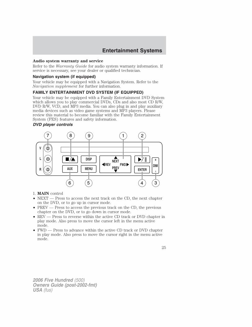
FAMILY ENTERTAINMENT DVD SYSTEM (IF EQUIPPED)Your vehicle may be equipped with a Family Entertainment DVD Systemwhich allows you to play commercial DVDs, CDs and also most CD R/W,DVD R/W, VCD, and MP3 media. You can also plug in and play auxiliarymedia devices such as video game systems and MP3 players. Pleasereview this material to become familiar with the Family EntertainmentSystem (FES) features and safety information.DVD player controls
1. MAIN control• NEXT — Press to access the next track on the CD, the next chapter
on the DVD, or to go up in cursor mode.• PREV — Press to access the previous track on the CD, the previous
chapter on the DVD, or to go down in cursor mode.• REV — Press to reverse within the active CD track or DVD chapter in
play mode. Also press to move the cursor left in the menu activemode.
• FWD — Press to advance within the active CD track or DVD chapterin play mode. Also press to move the cursor right in the menu activemode.
2006 Five Hundred (500)Owners Guide (post-2002-fmt)USA (fus)
Entertainment Systems
25
2. PLAY/PAUSE control
Press to playback or pause the DVD.
3. DIM control
Press (+) to increase or (-) to decrease the brightness on the screen.
4. ENTER control
Press to select the function highlighted on the active menu. ENTER mayalso be used by some user interactive discs during movie play.
5. MENU control
Press to bring up the disc menu.
6. AUX control
Press to switch DVD player from play mode to auxiliary mode.
7. Auxiliary jacks
Input jacks for standard video/audio media device.
8. STOP/EJECT control
Press once to stop a disc from playing. Press a second time to eject thedisc. (If a disc is not playing, but is present in the system, pressing ejectwill eject the disc).
9. DISPLAY (DISP) control
Press to enable the on screen display of the player’s menu and user’sdisplay adjustments. Double click the DISP button to change the formatof the display. If the DVD disc format is NORMAL, it can be changed tofull screen by selecting WIDE SCREEN. Use the NEXT and PREV buttonto scroll through the different format of the display. Please note that thescreen quality will degrade if the display mode is changed to “Zoom.”
DVD control features
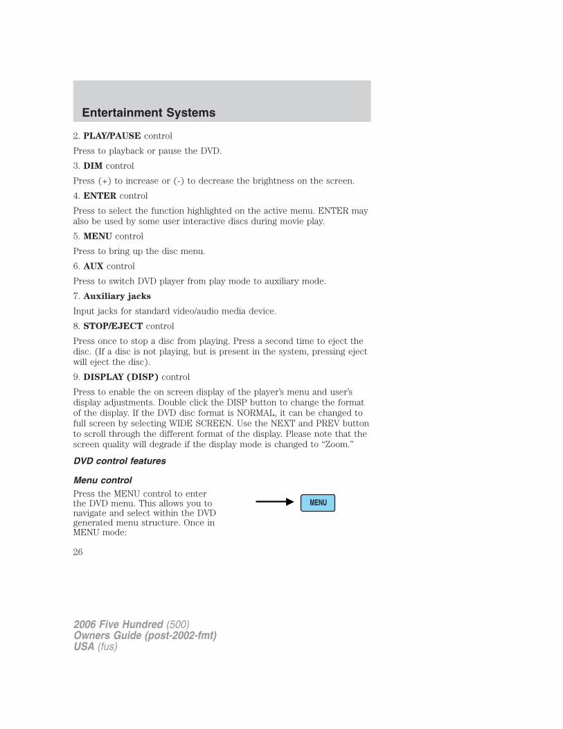
Menu controlPress the MENU control to enterthe DVD menu. This allows you tonavigate and select within the DVDgenerated menu structure. Once inMENU mode:
2006 Five Hundred (500)Owners Guide (post-2002-fmt)USA (fus)
Entertainment Systems
26
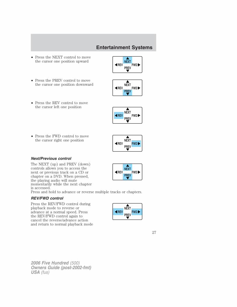
• Press the NEXT control to movethe cursor one position upward
• Press the PREV control to movethe cursor one position downward
• Press the REV control to movethe cursor left one position
• Press the FWD control to movethe cursor right one position
Next/Previous controlThe NEXT (up) and PREV (down)controls allows you to access thenext or previous track on a CD orchapter on a DVD. When pressed,the playing audio will mutemomentarily while the next chapteris accessed.Press and hold to advance or reverse multiple tracks or chapters.
REV/FWD controlPress the REV/FWD control duringplayback mode to reverse oradvance at a normal speed. Pressthe REV/FWD control again tocancel the reverse/advance actionand return to normal playback mode
NEXT
PREVREV FWD
NEXT
PREVREV FWD
NEXT
PREVREV FWD
NEXT
PREVREV FWD
NEXT
PREVREV FWD
NEXT
PREVREV FWD
2006 Five Hundred (500)Owners Guide (post-2002-fmt)USA (fus)
Entertainment Systems
27
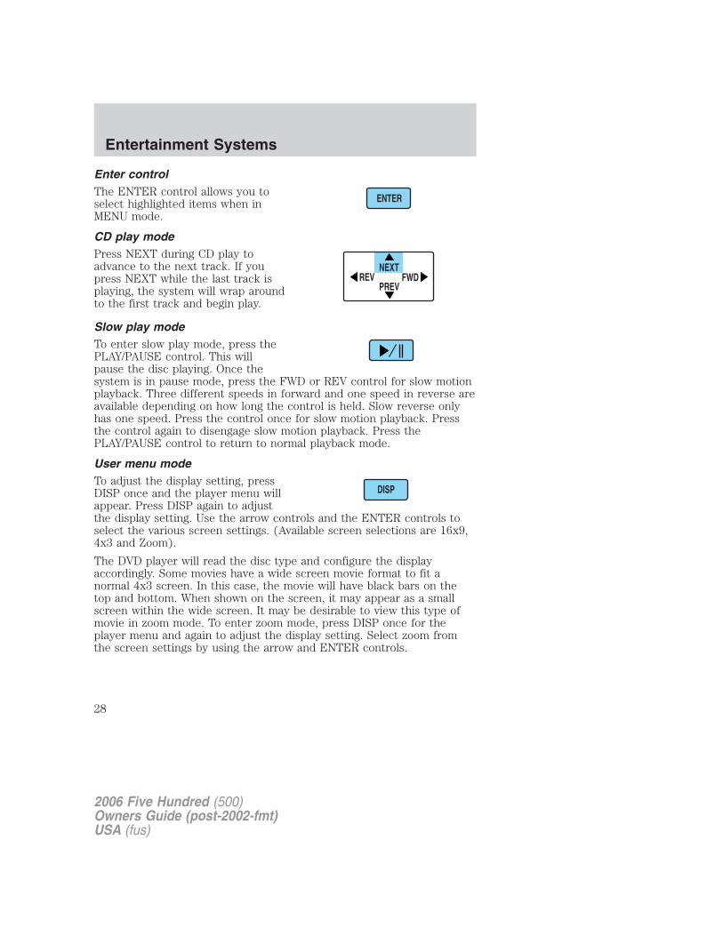
Enter controlThe ENTER control allows you toselect highlighted items when inMENU mode.
CD play modePress NEXT during CD play toadvance to the next track. If youpress NEXT while the last track isplaying, the system will wrap aroundto the first track and begin play.
Slow play modeTo enter slow play mode, press thePLAY/PAUSE control. This willpause the disc playing. Once thesystem is in pause mode, press the FWD or REV control for slow motionplayback. Three different speeds in forward and one speed in reverse areavailable depending on how long the control is held. Slow reverse onlyhas one speed. Press the control once for slow motion playback. Pressthe control again to disengage slow motion playback. Press thePLAY/PAUSE control to return to normal playback mode.
User menu modeTo adjust the display setting, pressDISP once and the player menu willappear. Press DISP again to adjustthe display setting. Use the arrow controls and the ENTER controls toselect the various screen settings. (Available screen selections are 16x9,4x3 and Zoom).
The DVD player will read the disc type and configure the displayaccordingly. Some movies have a wide screen movie format to fit anormal 4x3 screen. In this case, the movie will have black bars on thetop and bottom. When shown on the screen, it may appear as a smallscreen within the wide screen. It may be desirable to view this type ofmovie in zoom mode. To enter zoom mode, press DISP once for theplayer menu and again to adjust the display setting. Select zoom fromthe screen settings by using the arrow and ENTER controls.
ENTER
NEXT
PREVREV FWD
DISP
2006 Five Hundred (500)Owners Guide (post-2002-fmt)USA (fus)
Entertainment Systems
28
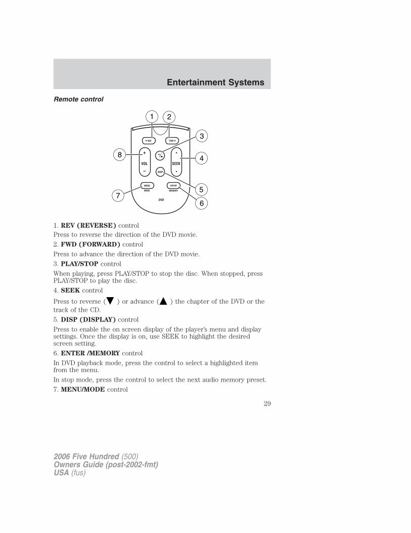
Remote control
1. REV (REVERSE) controlPress to reverse the direction of the DVD movie.
2. FWD (FORWARD) control
Press to advance the direction of the DVD movie.
3. PLAY/STOP control
When playing, press PLAY/STOP to stop the disc. When stopped, pressPLAY/STOP to play the disc.
4. SEEK control
Press to reverse ( ) or advance ( ) the chapter of the DVD or thetrack of the CD.
5. DISP (DISPLAY) control
Press to enable the on screen display of the player’s menu and displaysettings. Once the display is on, use SEEK to highlight the desiredscreen setting.
6. ENTER /MEMORY control
In DVD playback mode, press the control to select a highlighted itemfrom the menu.
In stop mode, press the control to select the next audio memory preset.
7. MENU/MODE control
2006 Five Hundred (500)Owners Guide (post-2002-fmt)USA (fus)
Entertainment Systems
29
In DVD playback mode, press to access the disc menu.
In stop mode, press to change media types (e.g. AM, FM, CD . . . )
8. VOL (VOLUME) control
Press (+) to increase or (-) to decrease the volume level.
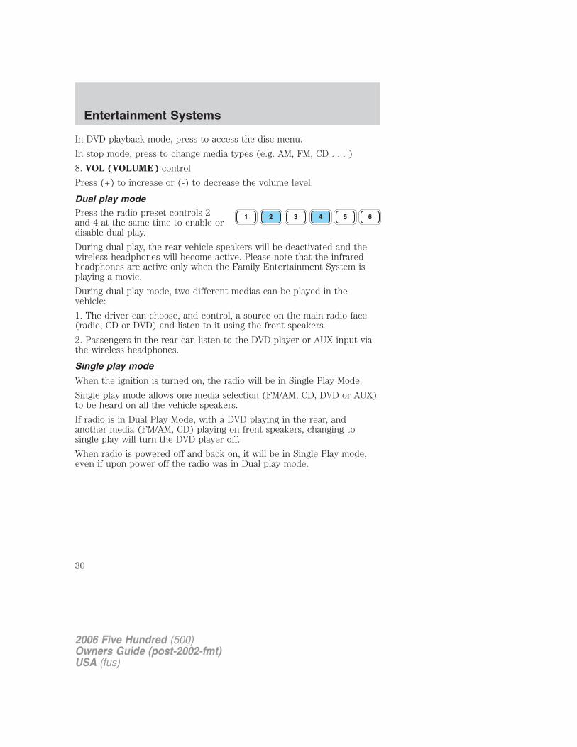
Dual play modePress the radio preset controls 2and 4 at the same time to enable ordisable dual play.
During dual play, the rear vehicle speakers will be deactivated and thewireless headphones will become active. Please note that the infraredheadphones are active only when the Family Entertainment System isplaying a movie.
During dual play mode, two different medias can be played in thevehicle:
1. The driver can choose, and control, a source on the main radio face(radio, CD or DVD) and listen to it using the front speakers.
2. Passengers in the rear can listen to the DVD player or AUX input viathe wireless headphones.
Single play mode
When the ignition is turned on, the radio will be in Single Play Mode.
Single play mode allows one media selection (FM/AM, CD, DVD or AUX)to be heard on all the vehicle speakers.
If radio is in Dual Play Mode, with a DVD playing in the rear, andanother media (FM/AM, CD) playing on front speakers, changing tosingle play will turn the DVD player off.
When radio is powered off and back on, it will be in Single Play mode,even if upon power off the radio was in Dual play mode.
1 2 3 4 5 6
2006 Five Hundred (500)Owners Guide (post-2002-fmt)USA (fus)
Entertainment Systems
30
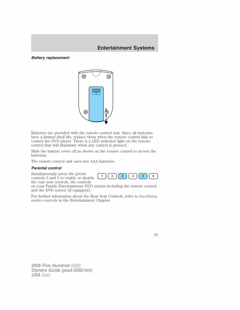
Battery replacement
Batteries are provided with the remote control unit. Since all batterieshave a limited shelf life, replace them when the remote control fails tocontrol the DVD player. There is a LED indicator light on the remotecontrol that will illuminate when any control is pressed.
Slide the battery cover off as shown on the remote control to access thebatteries.
The remote control unit uses two AAA batteries.
Parental controlSimultaneously press the presetcontrols 3 and 5 to enable or disablethe rear seat controls, the controlson your Family Entertainment DVD system including the remote control,and the DVD screen (if equipped).
For further information about the Rear Seat Controls, refer to Auxiliaryaudio controls in the Entertainment Chapter.
2006 Five Hundred (500)Owners Guide (post-2002-fmt)USA (fus)
Entertainment Systems
31
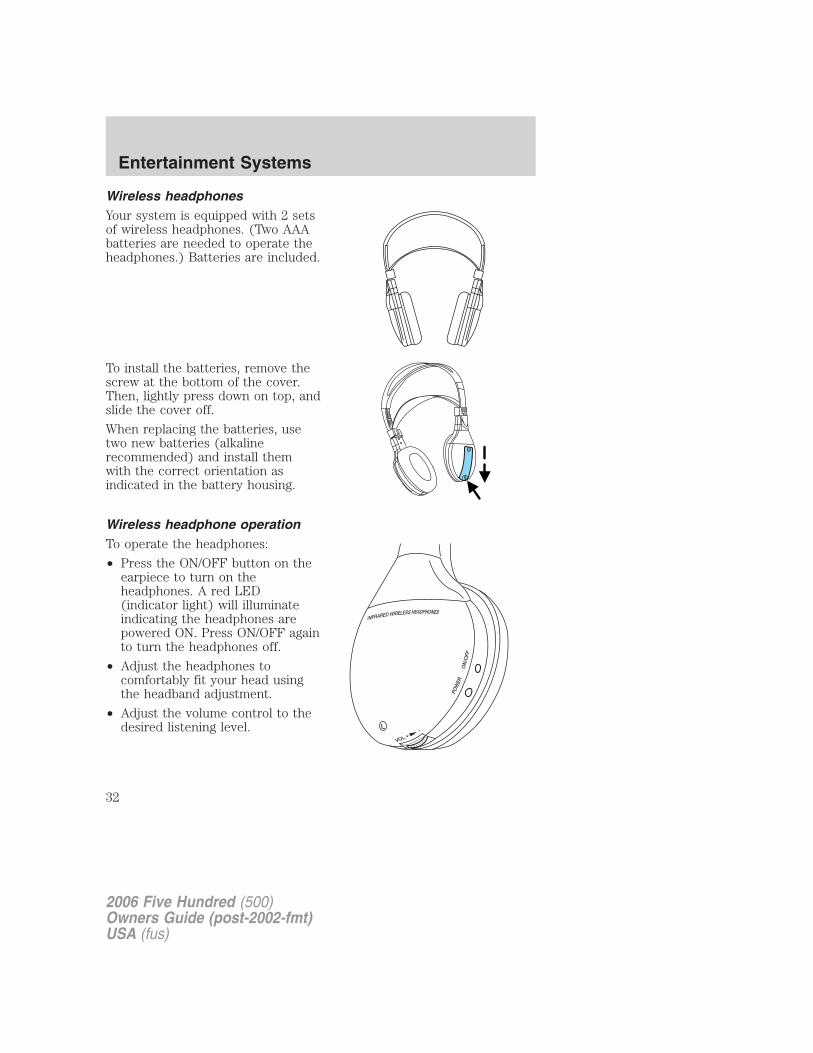
Wireless headphonesYour system is equipped with 2 setsof wireless headphones. (Two AAAbatteries are needed to operate theheadphones.) Batteries are included.
To install the batteries, remove thescrew at the bottom of the cover.Then, lightly press down on top, andslide the cover off.
When replacing the batteries, usetwo new batteries (alkalinerecommended) and install themwith the correct orientation asindicated in the battery housing.
Wireless headphone operationTo operate the headphones:
• Press the ON/OFF button on theearpiece to turn on theheadphones. A red LED(indicator light) will illuminateindicating the headphones arepowered ON. Press ON/OFF againto turn the headphones off.
• Adjust the headphones tocomfortably fit your head usingthe headband adjustment.
• Adjust the volume control to thedesired listening level.
2006 Five Hundred (500)Owners Guide (post-2002-fmt)USA (fus)
Entertainment Systems
32
Note: The volume level of the wireless headphones can only becontrolled by the thumbwheel. Neither the remote control nor the rearseat controls will affect the volume output of the wireless headphones.When not using the headphones, turn them off to preserve battery life.The headphones will automatically turn off after five minutes if they havenot received an infrared audio signal from the Family EntertainmentSystem (FES).Note: Ensure that the line of sight between the headphone and infraredtransmitter (mounted on the DVD housing) is not obstructed for optimalperformance.
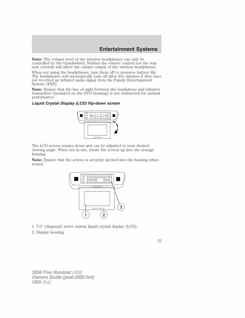
Liquid Crystal Display (LCD) flip-down screen
The LCD screen rotates down and can be adjusted to your desiredviewing angle. When not in use, rotate the screen up into the storagehousing.
Note: Ensure that the screen is securely latched into the housing whenstored.
1. 7.0” (diagonal) active matrix liquid crystal display (LCD).
2. Display housing.
2006 Five Hundred (500)Owners Guide (post-2002-fmt)USA (fus)
Entertainment Systems
33
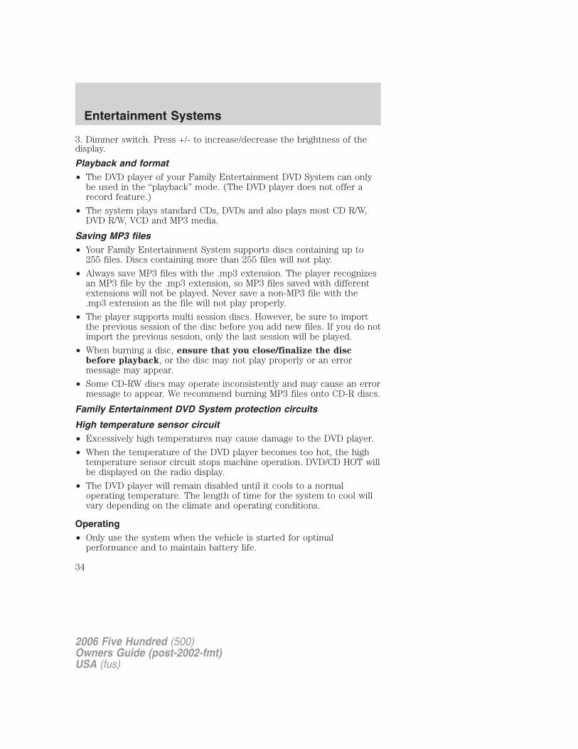
3. Dimmer switch. Press +/- to increase/decrease the brightness of thedisplay.
Playback and format• The DVD player of your Family Entertainment DVD System can only
be used in the “playback” mode. (The DVD player does not offer arecord feature.)
• The system plays standard CDs, DVDs and also plays most CD R/W,DVD R/W, VCD and MP3 media.
Saving MP3 files• Your Family Entertainment System supports discs containing up to
255 files. Discs containing more than 255 files will not play.
• Always save MP3 files with the .mp3 extension. The player recognizesan MP3 file by the .mp3 extension, so MP3 files saved with differentextensions will not be played. Never save a non-MP3 file with the.mp3 extension as the file will not play properly.
• The player supports multi session discs. However, be sure to importthe previous session of the disc before you add new files. If you do notimport the previous session, only the last session will be played.
• When burning a disc, ensure that you close/finalize the discbefore playback, or the disc may not play properly or an errormessage may appear.
• Some CD-RW discs may operate inconsistently and may cause an errormessage to appear. We recommend burning MP3 files onto CD-R discs.
Family Entertainment DVD System protection circuits
High temperature sensor circuit• Excessively high temperatures may cause damage to the DVD player.
• When the temperature of the DVD player becomes too hot, the hightemperature sensor circuit stops machine operation. DVD/CD HOT willbe displayed on the radio display.
• The DVD player will remain disabled until it cools to a normaloperating temperature. The length of time for the system to cool willvary depending on the climate and operating conditions.
Operating• Only use the system when the vehicle is started for optimal
performance and to maintain battery life.
2006 Five Hundred (500)Owners Guide (post-2002-fmt)USA (fus)
Entertainment Systems
34
• If the Family Entertainment System (FES) is playing and the ignitionis turned OFF, the system will turn off, and suspend playback. Whenthe ignition is turned on again, playback will begin from the lastselected media source when the play control is pressed.
• To disable the DVD player rear controls, simultaneously press the 3and 5 memory presets on the radio face. To enable the DVD playerrear controls again, press the 3 and 5 presets simultaneously.
• The DVD player is only capable of reading the bottom side of a disc.When inserting a single sided disc, the label should be up. For amulti-sided disc, the desired play side should be down when the discis inserted into the player.
• DVDs are formatted by regions. This DVD system can only play region1 DVDs (DVDs manufactured for U.S. and Canada).
This unit is designed to play commercially pressed 4.75 (12 cm)audio compact discs and DVDs only. Due to technicalincompatibility, certain recordable and re-recordable compactdiscs may not function correctly when used in Ford DVD/CDplayers. Irregular shaped discs, discs with a scratch protectionfilm attached, and discs with homemade paper (adhesive) labelsshould not be inserted into the player. The label may peel andcause the disc to become jammed. It is recommended thathomemade discs be identified with permanent felt tip markerrather than adhesive labels. Ball point pens may damage discs.Please contact your dealer for further information.
Inserting a CD/DVDWith the ignition ON, inserting a CD/DVD into the DVD playerautomatically turns ON the FES and playback should begin immediately.The counter is automatically reset to 0:00:00 when any disc is insertedinto the FES.Removing a CD/DVD (while playing)1. Press the STOP/EJECT control to stop playback if a disc is playing.2. Press the STOP/EJECT control again to eject the CD/DVD.If the CD/DVD is not removed within the allotted time, the system willpull the CD/DVD back into the system for safety purposes.If the CD/DVD will not eject from the system, press and hold the EJECTcontrol for approximately 2 seconds. The disc should eject whether thevehicle ignition is ON or OFF.Playing an auxiliary device1. Connect the video line from your video device to the YELLOWauxiliary input jack.
2006 Five Hundred (500)Owners Guide (post-2002-fmt)USA (fus)
Entertainment Systems
35
2. Connect the left and right audio lines to the WHITE (left) and RED(right) auxiliary input jacks respectively.3. Press the MODE control repeatedly until DVD/CD AUX (no disc inplayer) or DVD/CD play (disc in player) illuminates in the radio display.If a disc is in the system, playback should begin. To enable the auxinputs, press the STOP control or press the AUX control on the DVDplayer.
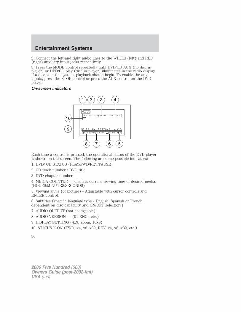
On-screen indicators
Each time a control is pressed, the operational status of the DVD playeris shown on the screen. The following are some possible indicators:
1. DVD/ CD STATUS (PLAY/FWD/REV/PAUSE)
2. CD track number / DVD title
3. DVD chapter number
4. MEDIA COUNTER — displays current viewing time of desired media.(HOURS:MINUTES:SECONDS)
5. Viewing angle (of picture) - Adjustable with cursor controls andENTER control.
6. Subtitles (specific language type - English, Spanish or French,dependent on disc capability and ON/OFF selection.)
7. AUDIO OUTPUT (not changeable)
8. AUDIO VERSION — (01 ENG., etc.)
9. DISPLAY SETTING (4x3, Zoom, 16x9)
10. STATUS ICON (FWD, x4, x8, x32, REV, x4, x8, x32, etc.)
2006 Five Hundred (500)Owners Guide (post-2002-fmt)USA (fus)
Entertainment Systems
36
Safety informationRead all the safety and operating instructions before operating thesystem and retain for future reference.
• Do not attempt to service, repair or modify the Family EntertainmentDVD System. See your Ford or Lincoln Mercury dealer.
• Do not insert foreign objects into the DVD compartment.
The front glass on the flip-down liquid crystal display (LCD) maybreak when hit with a hard surface. If the glass breaks, do not
touch the liquid crystalline material. In case of contact with skin, washimmediately with soap and water.
Do not expose the flip-down liquid crystal display (LCD) to directsunlight or intensive ultraviolet rays for extensive periods oftime. Ultraviolet rays deteriorate the liquid crystal.
• Ensure that you review User Manuals for video games and video gameequipment when used as auxiliary inputs for your FamilyEntertainment DVD System.
• Do not operate video games or video equipment if the power cordsand/or cables are broken, split or damaged. Carefully place cordsand/or cables where they will not be stepped on or interfere with theoperation of seats and/or compartments.
• Disconnect video games and video equipment power cords and/orcables when not in use.
• Avoid touching auxiliary input jacks with your fingers. Do not blow onthem or allow them to get wet or dirty.
• Do not clean any part of the DVD player with benzene, paint thinneror any other solvent.
Whenever a warning notice is received, the radio volume will belowered to a volume that will allow the tones to be heard. Theradio volume will return to the previous level after the warningnotice is complete.
2006 Five Hundred (500)Owners Guide (post-2002-fmt)USA (fus)
Entertainment Systems
37
Federal Communication Commission (FCC) ComplianceChanges or modifications not approved by Ford or Lincoln Mercury couldvoid user’s authority to operate the equipment. This equipment has beentested and found to comply with the limits for a Class B digital device,pursuant to Part 15 of the FCC Rules. These limits are designed toprovide reasonable protection against harmful interference in aresidential installation. This equipment generates, uses and can radiateradio frequency energy. If not installed and used in accordance with theinstructions, the Family Entertainment System (FES) may cause harmfulinterference with radio communications.
However, there is no guarantee that interference will not occur in aparticular installation. If this equipment does cause harmful interferenceto radio or television reception, (which can be determined by turning theequipment off and on), the user is encouraged to consult the dealer oran experienced radio/TV technician for help.
Care and service of the DVD player
Environmental extremesDVD players that are subjected to harsh environmental conditions maybe damaged or perform at less than optimal capability. To avoid theseoutcomes, whenever possible avoid exposing your DVD player to:
• extremely hot or cold temperatures.
• direct sunlight.
• high humidity.
• a dusty environment.
• locations where strong magnetic fields are generated.
Temperature extremesWhen the vehicle is parked under direct sunlight or in an extremely coldplace for a long period of time, wait until the cabin temperature of thevehicle is at normal temperature before operating the system.
Humidity and moisture condensationMoisture in the air will condense in the DVD player under extremelyhumid conditions or when moving from a cold to a warm location. Ifmoisture condensation occurs, do not insert a CD or DVD into theplayer. If one is already in the player, remove it and turn the DVD playerON to dry the moisture before inserting a DVD. This could take an houror more depending on the amount of moisture.
2006 Five Hundred (500)Owners Guide (post-2002-fmt)USA (fus)
Entertainment Systems
38

Cleaning the liquid crystal display (LCD) flip-down screenClean the display screen by applying a small amount of water or anyammonia-based household glass cleaner directly to a soft cloth. Rub thescreen gently until the dust, dirt or fingerprints are removed. Do notspray the screen directly with water or glass cleaning solvents. Oversprayfrom these fluids could drip down into the internal electronics of thescreen and cause damage. Do not apply excessive pressure whilecleaning the screen.
Foreign substancesExercise care to prevent dirt and foreign objects from entering the DVDplayer compartment. If liquid is accidentally spilled onto the system,immediately turn the system OFF and consult a qualified servicetechnician.
Cleaning compact discsInspect all discs for contamination before playing. If necessary, cleandiscs only with an approved CD cleaner and wipe from the center out tothe edge. Do not wipe in a circular motion.
Cleaning the DVD playerClean the exterior of the DVD player with a damp cloth. Do not use CDcleaning kits or CDs intended to clean the interior of your DVD player.Use of these products may damage your system.
2006 Five Hundred (500)Owners Guide (post-2002-fmt)USA (fus)
Entertainment Systems
39
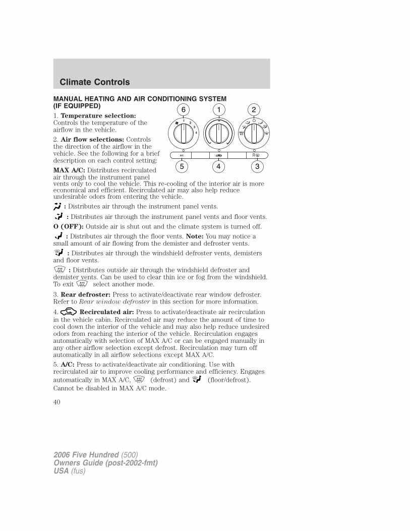
MANUAL HEATING AND AIR CONDITIONING SYSTEM(IF EQUIPPED)1. Temperature selection:Controls the temperature of theairflow in the vehicle.
2. Air flow selections: Controlsthe direction of the airflow in thevehicle. See the following for a briefdescription on each control setting:
MAX A/C: Distributes recirculatedair through the instrument panelvents only to cool the vehicle. This re-cooling of the interior air is moreeconomical and efficient. Recirculated air may also help reduceundesirable odors from entering the vehicle.
: Distributes air through the instrument panel vents.
: Distributes air through the instrument panel vents and floor vents.
O (OFF): Outside air is shut out and the climate system is turned off.
: Distributes air through the floor vents. Note: You may notice asmall amount of air flowing from the demister and defroster vents.
: Distributes air through the windshield defroster vents, demistersand floor vents.
: Distributes outside air through the windshield defroster anddemister vents. Can be used to clear thin ice or fog from the windshield.To exit select another mode.
3. Rear defroster: Press to activate/deactivate rear window defroster.Refer to Rear window defroster in this section for more information.
4. Recirculated air: Press to activate/deactivate air recirculationin the vehicle cabin. Recirculated air may reduce the amount of time tocool down the interior of the vehicle and may also help reduce undesiredodors from reaching the interior of the vehicle. Recirculation engagesautomatically with selection of MAX A/C or can be engaged manually inany other airflow selection except defrost. Recirculation may turn offautomatically in all airflow selections except MAX A/C.
5. A/C: Press to activate/deactivate air conditioning. Use withrecirculated air to improve cooling performance and efficiency. Engagesautomatically in MAX A/C, (defrost) and (floor/defrost).Cannot be disabled in MAX A/C mode.
2006 Five Hundred (500)Owners Guide (post-2002-fmt)USA (fus)
Climate Controls
40
6. Fan speed adjustment: Controls the volume of air circulated in thevehicle.
Operating tips• To reduce fog build up on the windshield during humid weather, place
the air flow selector in the position.
• To reduce humidity build up inside the vehicle: do not drive with theairflow selector in the O (OFF) or with recirculated air engaged.
• Do not put objects under the front seats that will interfere with theairflow to the back seats.
• Remove any snow, ice or leaves from the air intake area at the base ofthe windshield.
• For maximum cooling performance (MAX A/C):In the MAX A/C mode:• Move the temperature control selector to the coldest setting.• Set the fan to the highest speed initially, then adjust to maintain
passenger comfort.
In the and modes:
• Move the temperature control selector to the coldest setting.
• Select A/C and recirculated air . Use with A/C to providecolder airflow.
• Set the fan to the highest speed initially, then adjust to maintainpassenger comfort.
In extremely cold temperatures, to maximize overall heater performanceit is suggested to not operate the auxiliary system (if so equipped) untilthe engine temperature gauge crosses into the normal operating range.
To aid in side window defogging/demisting in cold weather:
1. Select .
2. Select A/C.
3. Set the temperature control to full heat.
4. Set the fan speed to the highest setting.
5. Direct the outer instrument panel vents towards the side windows.
Do not place objects on top of the instrument panel as theseobjects may become projectiles in a collision or sudden stop.
2006 Five Hundred (500)Owners Guide (post-2002-fmt)USA (fus)
Climate Controls
41
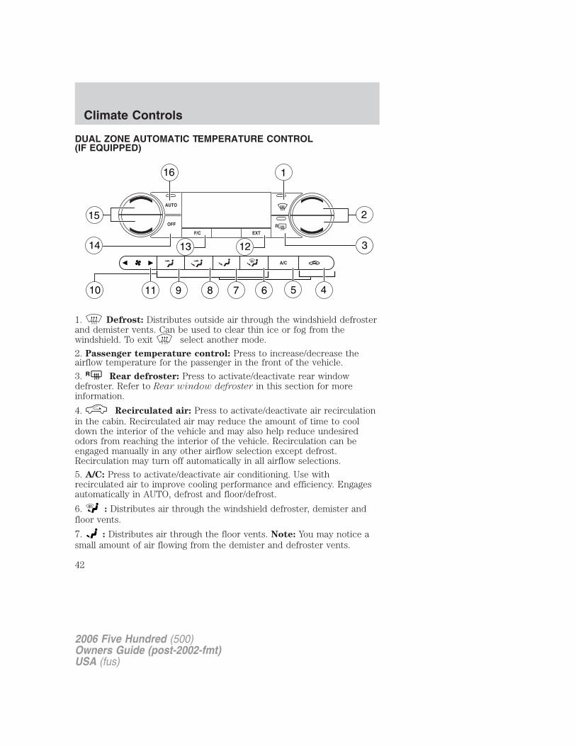
DUAL ZONE AUTOMATIC TEMPERATURE CONTROL(IF EQUIPPED)
1. Defrost: Distributes outside air through the windshield defrosterand demister vents. Can be used to clear thin ice or fog from thewindshield. To exit select another mode.
2. Passenger temperature control: Press to increase/decrease theairflow temperature for the passenger in the front of the vehicle.
3. R Rear defroster: Press to activate/deactivate rear windowdefroster. Refer to Rear window defroster in this section for moreinformation.
4. Recirculated air: Press to activate/deactivate air recirculationin the cabin. Recirculated air may reduce the amount of time to cooldown the interior of the vehicle and may also help reduce undesiredodors from reaching the interior of the vehicle. Recirculation can beengaged manually in any other airflow selection except defrost.Recirculation may turn off automatically in all airflow selections.
5. A/C: Press to activate/deactivate air conditioning. Use withrecirculated air to improve cooling performance and efficiency. Engagesautomatically in AUTO, defrost and floor/defrost.
6. : Distributes air through the windshield defroster, demister andfloor vents.
7. : Distributes air through the floor vents. Note: You may notice asmall amount of air flowing from the demister and defroster vents.
2006 Five Hundred (500)Owners Guide (post-2002-fmt)USA (fus)
Climate Controls
42
8. : Distributes air through the instrument panel and floor vents.
9. : Distributes air through the instrument panel vents.
10. Manual override controls: Allows you to manually select whereairflow is directed. To return to full automatic control, press AUTO.
11. Front fan speed control: Press to manually increase ordecrease the fan speed. To return to automatic fan operation, pressAUTO.
12. EXT: Press to display outside temperature. Press again to displaycabin temperature settings.
13. F/C (Temperature conversions): Press to switch temperaturedisplay between ° Fahrenheit and ° Celsius.
14. OFF: Outside air is shut out and the climate control system is turnedoff.
15. Driver temperature control: Press to increase/decrease thetemperature on the driver side of the cabin. Sets the passenger sidetemperature also when DUAL is disengaged. The recommended vehiclecabin setting is between 72°F (22°C) and 75°F (24°C).
Dual temperature control: Press and hold the AUTO button toengage-disengage separate passenger side temperature control.
16. AUTO: To engage automatic temperature control, press AUTO andselect the desired temperature using the temperature control. Thesystem will automatically determine fan speed, airflow location, A/C onor off, and outside or recirculated air, to heat or cool the vehicle to reachthe desired temperature.
2006 Five Hundred (500)Owners Guide (post-2002-fmt)USA (fus)
Climate Controls
43
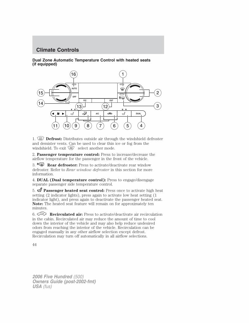
Dual Zone Automatic Temperature Control with heated seats(if equipped)
1. Defrost: Distributes outside air through the windshield defrosterand demister vents. Can be used to clear thin ice or fog from thewindshield. To exit select another mode.
2. Passenger temperature control: Press to increase/decrease theairflow temperature for the passenger in the front of the vehicle.
3. R Rear defroster: Press to activate/deactivate rear windowdefroster. Refer to Rear window defroster in this section for moreinformation.
4. DUAL (Dual temperature control): Press to engage/disengageseparate passenger side temperature control.
5. Passenger heated seat control: Press once to activate high heatsetting (2 indicator lights), press again to activate low heat setting (1indicator light), and press again to deactivate the passenger heated seat.Note: The heated seat feature will remain on for approximately tenminutes.
6. Recirculated air: Press to activate/deactivate air recirculationin the cabin. Recirculated air may reduce the amount of time to cooldown the interior of the vehicle and may also help reduce undesiredodors from reaching the interior of the vehicle. Recirculation can beengaged manually in any other airflow selection except defrost.Recirculation may turn off automatically in all airflow selections.
2006 Five Hundred (500)Owners Guide (post-2002-fmt)USA (fus)
Climate Controls
44
7. A/C: Press to activate/deactivate air conditioning. Use withrecirculated air to improve cooling performance and efficiency. Engagesautomatically in AUTO, defrost and floor/defrost.8. Airflow direction control: Press to toggle through the airdistribution modes listed below. The selected mode will be shown in thedisplay.
: Distributes air through the instrument panel and center consolevents (if equipped).
: Distributes air through the instrument panel, floor and centerconsole vents (if equipped).
: Distributes air through the floor vents. Note: You may notice asmall amount of air flowing from the demister and defroster vents.
: Distributes air through the windshield defroster, demister and floorvents.9. Manual override controls: Allows you to manually select whereairflow is directed. To return to full automatic control, press AUTO.
10. Driver heated seat control: Press to heat the driver seat. Pressonce to activate high heat (two indicator lights). Press again to activatelow heat (one indicator light). Press again to deactivate the driverheated seat. Note: The heated seat feature will remain on forapproximately ten minutes.
11. Front fan speed control: Press to manually increase ordecrease the fan speed. To return to automatic fan operation, pressAUTO.12. EXT: Press to display outside temperature. Press again to displaycabin temperature settings.13. F/C (Temperature conversions): Press to switch temperaturedisplay between ° Fahrenheit and ° Celsius.14. OFF: Outside air is shut out and the climate control system is turnedoff.15. Driver temperature control: Press to increase/decrease thetemperature on the driver side of the cabin. Sets the passenger sidetemperature also when DUAL is disengaged. The recommended vehiclecabin setting is between 72°F (22°C) and 75°F (24°C).16. AUTO: Press to engage automatic temperature control. Select thedesired temperature using the temperature control. The system willautomatically determine fan speed, airflow location, A/C on or off, andoutside or recirculated air, to heat or cool the vehicle to reach thedesired temperature.
2006 Five Hundred (500)Owners Guide (post-2002-fmt)USA (fus)
Climate Controls
45
Operating tips• To reduce fog build up on the windshield during humid weather, place
the air flow selector in the position.
• To reduce humidity build up inside the vehicle: do not drive with theairflow selector in the OFF or with recirculated air engaged.
• Do not put objects under the front seats that will interfere with theairflow to the back seats.
• Remove any snow, ice or leaves from the air intake area at the base ofthe windshield.
• For maximum cooling performance (MAX A/C):
In AUTO mode, press AUTO control and set to desired temperature.
In manual override control, select or , A/C and recirculatedair and set the temperature to 60°F (16°C). Set the fan to thehighest speed initially, then adjust to maintain passenger comfort.
• To improve the A/C cool down, drive with the windows slightly openfor 2–3 minutes after starting the vehicle or until the vehicle has“aired out.”
In extremely cold temperatures, to maximize overall heater performanceit is suggested to not operate the auxiliary system (if so equipped) untilthe engine temperature gauge crosses into the normal operating range.
To aid in side window defogging/demisting in cold weather:
1. Select .
2. Select A/C.
3. Adjust the temperature control to maintain comfort.
4. Set the fan to the highest speed.
5. Direct the outer instrument panel vents towards the side windows.
Do not place objects on top of the instrument panel as theseobjects may become projectiles in a collision or sudden stop.
2006 Five Hundred (500)Owners Guide (post-2002-fmt)USA (fus)
Climate Controls
46
REAR WINDOW DEFROSTERR
The rear defroster control is located on the climate control panel andworks to clear the rear window of fog and thin ice.
The ignition must be in the 3 (RUN) position to operate the rear windowdefroster.
The rear defroster turns off automatically after 10 minutes or when theignition is turned to the 1 (LOCK) position. To manually turn off thedefroster before 10 minutes have passed, push the control again.
Do not use razor blades or other sharp objects to clean the insideof the rear window or to remove decals from the inside of therear window. This may cause damage to the heated grid lines andwill not be covered by your warranty.
2006 Five Hundred (500)Owners Guide (post-2002-fmt)USA (fus)
Climate Controls
47
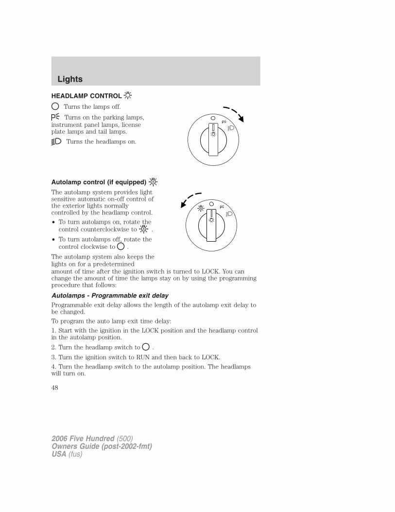
HEADLAMP CONTROL
Turns the lamps off.
Turns on the parking lamps,instrument panel lamps, licenseplate lamps and tail lamps.
Turns the headlamps on.
Autolamp control (if equipped)
The autolamp system provides lightsensitive automatic on-off control ofthe exterior lights normallycontrolled by the headlamp control.
• To turn autolamps on, rotate thecontrol counterclockwise to .
• To turn autolamps off, rotate thecontrol clockwise to .
The autolamp system also keeps thelights on for a predeterminedamount of time after the ignition switch is turned to LOCK. You canchange the amount of time the lamps stay on by using the programmingprocedure that follows:
Autolamps - Programmable exit delayProgrammable exit delay allows the length of the autolamp exit delay tobe changed.
To program the auto lamp exit time delay:
1. Start with the ignition in the LOCK position and the headlamp controlin the autolamp position.
2. Turn the headlamp switch to .
3. Turn the ignition switch to RUN and then back to LOCK.
4. Turn the headlamp switch to the autolamp position. The headlampswill turn on.
P
2006 Five Hundred (500)Owners Guide (post-2002-fmt)USA (fus)
Lights
48
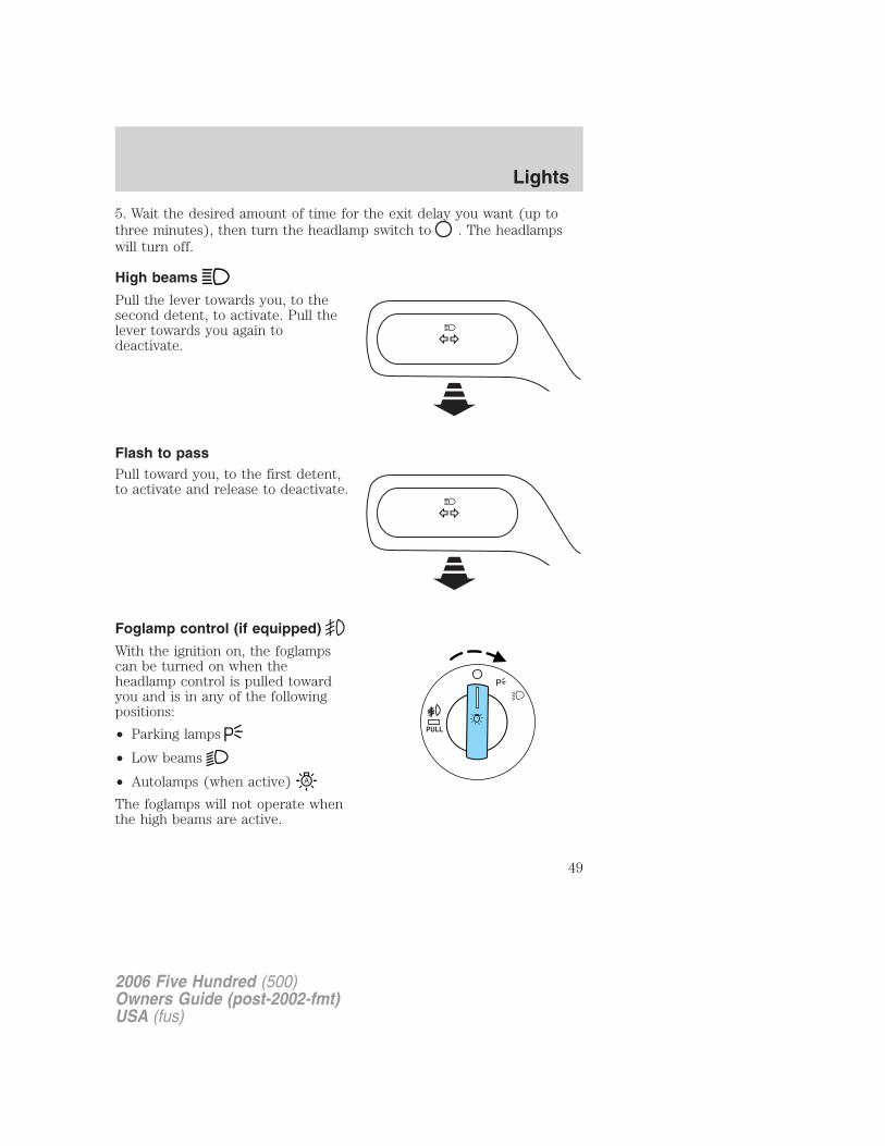
5. Wait the desired amount of time for the exit delay you want (up tothree minutes), then turn the headlamp switch to . The headlampswill turn off.
High beams
Pull the lever towards you, to thesecond detent, to activate. Pull thelever towards you again todeactivate.
Flash to passPull toward you, to the first detent,to activate and release to deactivate.
Foglamp control (if equipped)
With the ignition on, the foglampscan be turned on when theheadlamp control is pulled towardyou and is in any of the followingpositions:
• Parking lamps
• Low beams
• Autolamps (when active)
The foglamps will not operate whenthe high beams are active.
2006 Five Hundred (500)Owners Guide (post-2002-fmt)USA (fus)
Lights
49
Daytime running lamps (DRL) (if equipped)
Turns the headlamps on with a reduced output.
To activate:
• the ignition must be in the ON position,
• the headlamp control is in the OFF, autolamps or parking lampposition and
• the transmission must be out of the Park position.
Always remember to turn on your headlamps at dusk or duringinclement weather. The Daytime Running Lamp (DRL) system
does not activate the tail lamps and generally may not provideadequate lighting during these conditions. Failure to activate yourheadlamps under these conditions may result in a collision.
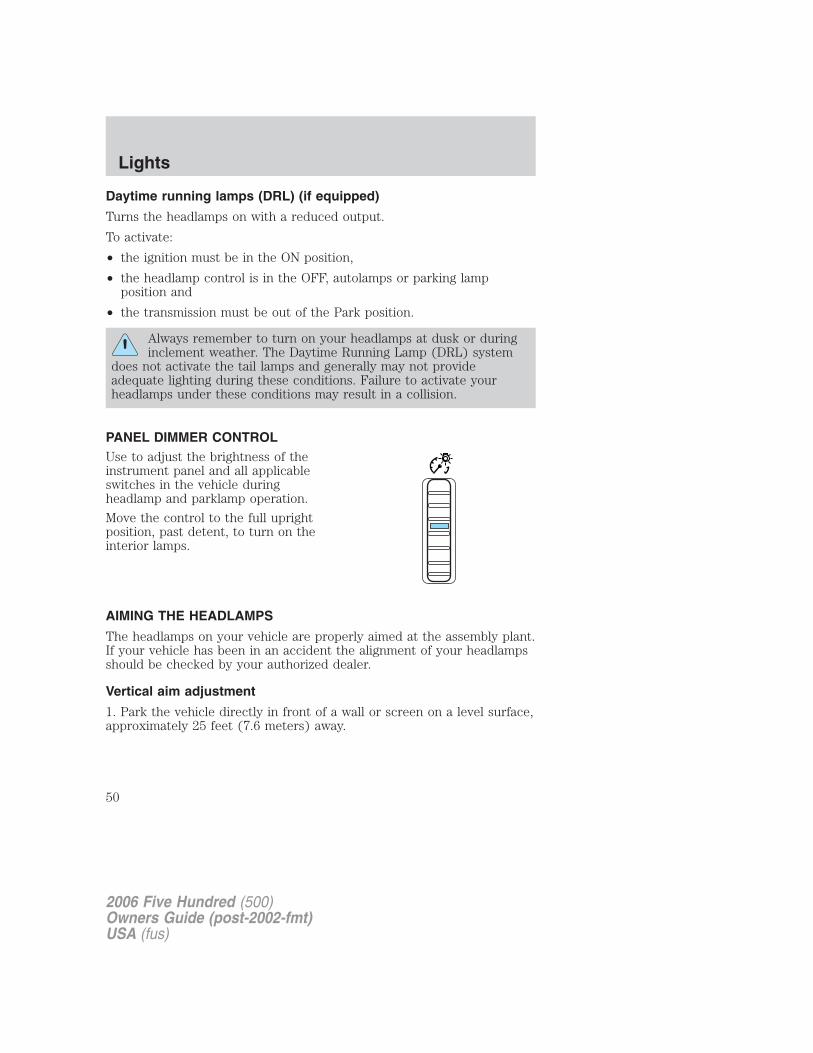
PANEL DIMMER CONTROLUse to adjust the brightness of theinstrument panel and all applicableswitches in the vehicle duringheadlamp and parklamp operation.
Move the control to the full uprightposition, past detent, to turn on theinterior lamps.
AIMING THE HEADLAMPS
The headlamps on your vehicle are properly aimed at the assembly plant.If your vehicle has been in an accident the alignment of your headlampsshould be checked by your authorized dealer.
Vertical aim adjustment
1. Park the vehicle directly in front of a wall or screen on a level surface,approximately 25 feet (7.6 meters) away.
2006 Five Hundred (500)Owners Guide (post-2002-fmt)USA (fus)
Lights
50
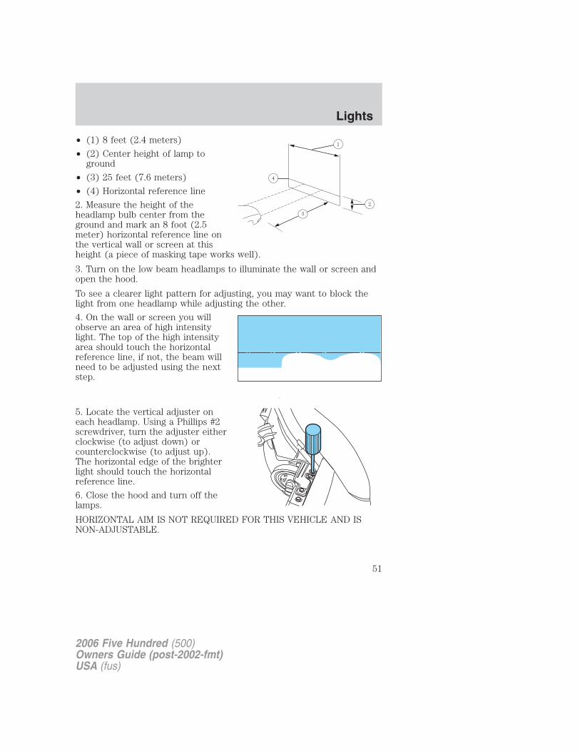
• (1) 8 feet (2.4 meters)
• (2) Center height of lamp toground
• (3) 25 feet (7.6 meters)
• (4) Horizontal reference line
2. Measure the height of theheadlamp bulb center from theground and mark an 8 foot (2.5meter) horizontal reference line onthe vertical wall or screen at thisheight (a piece of masking tape works well).
3. Turn on the low beam headlamps to illuminate the wall or screen andopen the hood.
To see a clearer light pattern for adjusting, you may want to block thelight from one headlamp while adjusting the other.
4. On the wall or screen you willobserve an area of high intensitylight. The top of the high intensityarea should touch the horizontalreference line, if not, the beam willneed to be adjusted using the nextstep.
5. Locate the vertical adjuster oneach headlamp. Using a Phillips #2screwdriver, turn the adjuster eitherclockwise (to adjust down) orcounterclockwise (to adjust up).The horizontal edge of the brighterlight should touch the horizontalreference line.
6. Close the hood and turn off thelamps.
HORIZONTAL AIM IS NOT REQUIRED FOR THIS VEHICLE AND ISNON-ADJUSTABLE.
2006 Five Hundred (500)Owners Guide (post-2002-fmt)USA (fus)
Lights
51
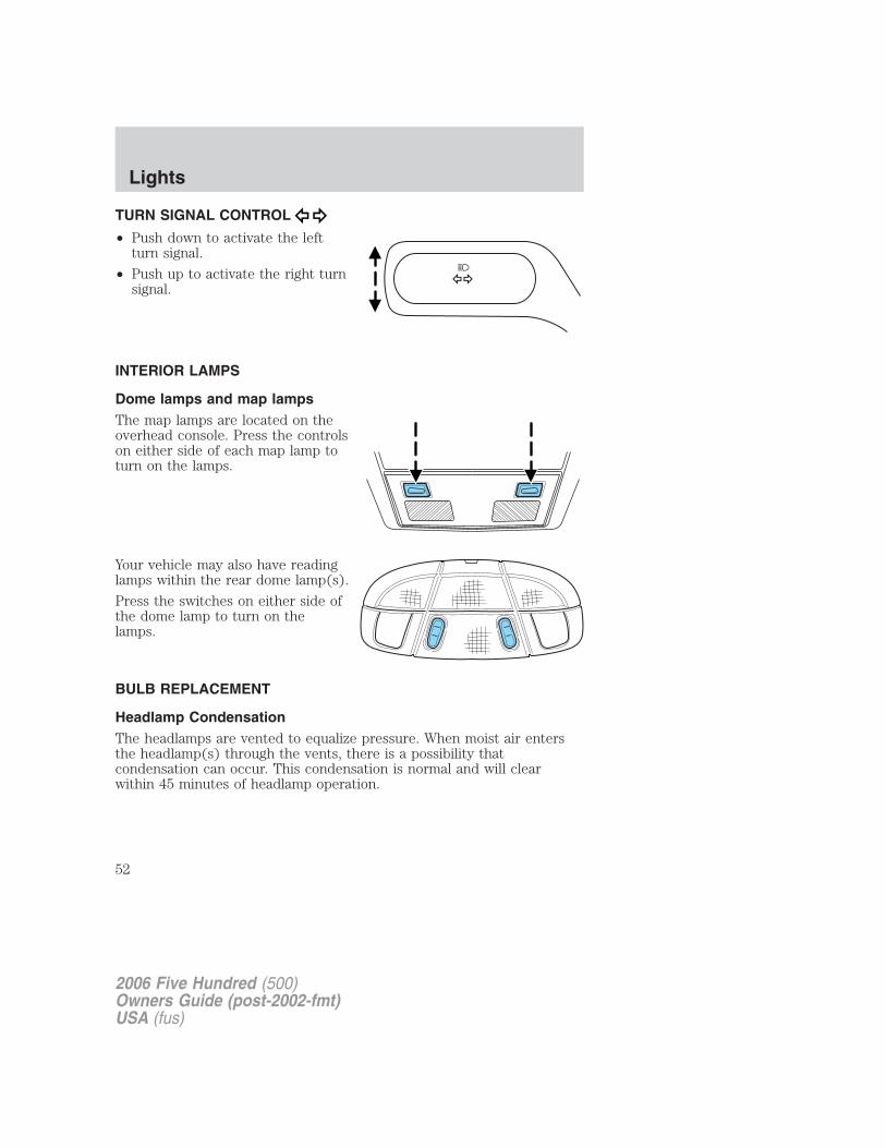
TURN SIGNAL CONTROL
• Push down to activate the leftturn signal.
• Push up to activate the right turnsignal.
INTERIOR LAMPS
Dome lamps and map lampsThe map lamps are located on theoverhead console. Press the controlson either side of each map lamp toturn on the lamps.
Your vehicle may also have readinglamps within the rear dome lamp(s).
Press the switches on either side ofthe dome lamp to turn on thelamps.
BULB REPLACEMENT
Headlamp CondensationThe headlamps are vented to equalize pressure. When moist air entersthe headlamp(s) through the vents, there is a possibility thatcondensation can occur. This condensation is normal and will clearwithin 45 minutes of headlamp operation.
2006 Five Hundred (500)Owners Guide (post-2002-fmt)USA (fus)
Lights
52
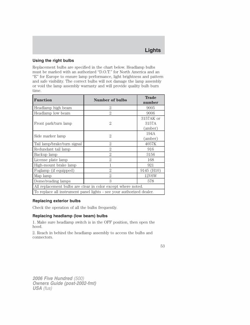
Using the right bulbs
Replacement bulbs are specified in the chart below. Headlamp bulbsmust be marked with an authorized “D.O.T.” for North America and an“E” for Europe to ensure lamp performance, light brightness and patternand safe visibility. The correct bulbs will not damage the lamp assemblyor void the lamp assembly warranty and will provide quality bulb burntime.
Function Number of bulbsTrade
number
Headlamp high beam 2 9005Headlamp low beam 2 9006
Front park/turn lamp 23157AK or
3157A(amber)
Side marker lamp 2194A
(amber)Tail lamp/brake/turn signal 2 4057KRedundant tail lamp 2 916Backup lamp 2 3156License plate lamp 2 168High-mount brake lamp 1 921Foglamp (if equipped) 2 9145 (H10)Map lamp 2 12V6WDome/reading lamps 3 578All replacement bulbs are clear in color except where noted.To replace all instrument panel lights - see your authorized dealer.
Replacing exterior bulbs
Check the operation of all the bulbs frequently.
Replacing headlamp (low beam) bulbs
1. Make sure headlamp switch is in the OFF position, then open thehood.
2. Reach in behind the headlamp assembly to access the bulbs andconnectors.
2006 Five Hundred (500)Owners Guide (post-2002-fmt)USA (fus)
Lights
53
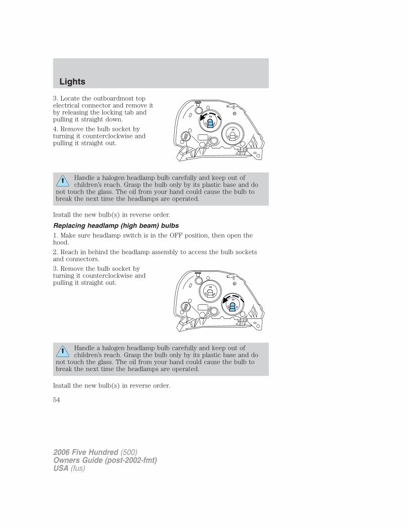
3. Locate the outboardmost topelectrical connector and remove itby releasing the locking tab andpulling it straight down.
4. Remove the bulb socket byturning it counterclockwise andpulling it straight out.
Handle a halogen headlamp bulb carefully and keep out ofchildren’s reach. Grasp the bulb only by its plastic base and do
not touch the glass. The oil from your hand could cause the bulb tobreak the next time the headlamps are operated.
Install the new bulb(s) in reverse order.
Replacing headlamp (high beam) bulbs1. Make sure headlamp switch is in the OFF position, then open thehood.
2. Reach in behind the headlamp assembly to access the bulb socketsand connectors.
3. Remove the bulb socket byturning it counterclockwise andpulling it straight out.
Handle a halogen headlamp bulb carefully and keep out ofchildren’s reach. Grasp the bulb only by its plastic base and do
not touch the glass. The oil from your hand could cause the bulb tobreak the next time the headlamps are operated.
Install the new bulb(s) in reverse order.
2006 Five Hundred (500)Owners Guide (post-2002-fmt)USA (fus)
Lights
54
Replacing front parking lamp/turn signal bulbs
1. Make sure headlamp switch is in the OFF position, then open thehood.
2. Reach up from the underside of the fascia to access the bulb socketsand connectors.
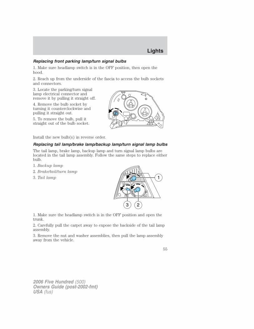
3. Locate the parking/turn signallamp electrical connector andremove it by pulling it straight off.
4. Remove the bulb socket byturning it counterclockwise andpulling it straight out.
5. To remove the bulb, pull itstraight out of the bulb socket.
Install the new bulb(s) in reverse order.
Replacing tail lamp/brake lamp/backup lamp/turn signal lamp bulbs
The tail lamp, brake lamp, backup lamp and turn signal lamp bulbs arelocated in the tail lamp assembly. Follow the same steps to replace eitherbulb.
1. Backup lamp
2. Brake/tail/turn lamp
3. Tail lamp
1. Make sure the headlamp switch is in the OFF position and open thetrunk.
2. Carefully pull the carpet away to expose the backside of the tail lampassembly.
3. Remove the nut and washer assemblies, then pull the lamp assemblyaway from the vehicle.
2006 Five Hundred (500)Owners Guide (post-2002-fmt)USA (fus)
Lights
55
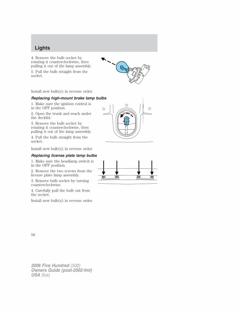
4. Remove the bulb socket byrotating it counterclockwise, thenpulling it out of the lamp assembly.
5. Pull the bulb straight from thesocket.
Install new bulb(s) in reverse order.
Replacing high-mount brake lamp bulbs1. Make sure the ignition control isin the OFF position.
2. Open the trunk and reach underthe decklid.
3. Remove the bulb socket byrotating it counterclockwise, thenpulling it out of the lamp assembly.
4. Pull the bulb straight from thesocket.
Install new bulb(s) in reverse order.
Replacing license plate lamp bulbs1. Make sure the headlamp switch isin the OFF position.
2. Remove the two screws from thelicense plate lamp assembly.
3. Remove bulb socket by turningcounterclockwise.
4. Carefully pull the bulb out fromthe socket.
Install new bulb(s) in reverse order.
2006 Five Hundred (500)Owners Guide (post-2002-fmt)USA (fus)
Lights
56
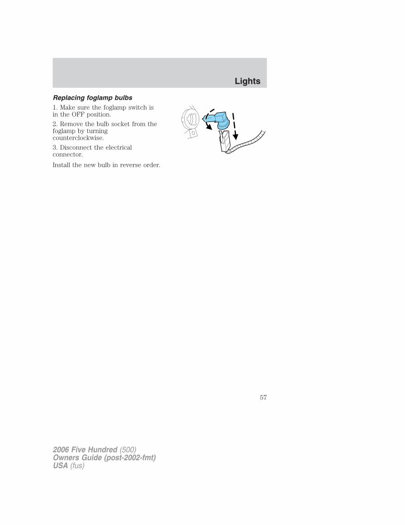
Replacing foglamp bulbs1. Make sure the foglamp switch isin the OFF position.
2. Remove the bulb socket from thefoglamp by turningcounterclockwise.
3. Disconnect the electricalconnector.
Install the new bulb in reverse order.
2006 Five Hundred (500)Owners Guide (post-2002-fmt)USA (fus)
Lights
57
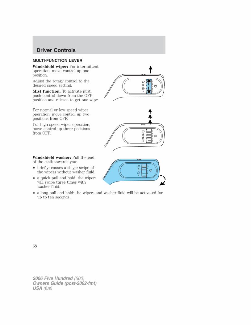
MULTI-FUNCTION LEVERWindshield wiper: For intermittentoperation, move control up oneposition.
Adjust the rotary control to thedesired speed setting.
Mist function: To activate mist,push control down from the OFFposition and release to get one wipe.
For normal or low speed wiperoperation, move control up twopositions from OFF.
For high speed wiper operation,move control up three positionsfrom OFF.
Windshield washer: Pull the endof the stalk towards you:
• briefly: causes a single swipe ofthe wipers without washer fluid.
• a quick pull and hold: the wiperswill swipe three times withwasher fluid.
• a long pull and hold: the wipers and washer fluid will be activated forup to ten seconds.
2006 Five Hundred (500)Owners Guide (post-2002-fmt)USA (fus)
Driver Controls
58
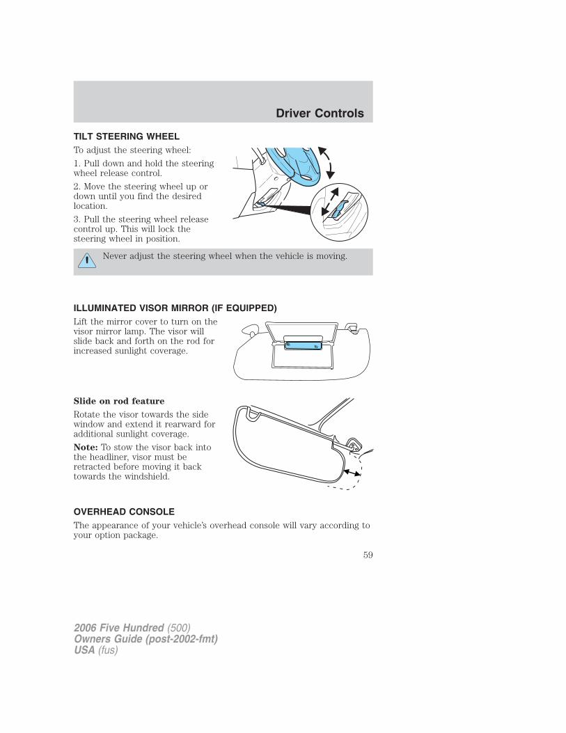
TILT STEERING WHEELTo adjust the steering wheel:
1. Pull down and hold the steeringwheel release control.
2. Move the steering wheel up ordown until you find the desiredlocation.
3. Pull the steering wheel releasecontrol up. This will lock thesteering wheel in position.
Never adjust the steering wheel when the vehicle is moving.
ILLUMINATED VISOR MIRROR (IF EQUIPPED)Lift the mirror cover to turn on thevisor mirror lamp. The visor willslide back and forth on the rod forincreased sunlight coverage.
Slide on rod feature
Rotate the visor towards the sidewindow and extend it rearward foradditional sunlight coverage.
Note: To stow the visor back intothe headliner, visor must beretracted before moving it backtowards the windshield.
OVERHEAD CONSOLEThe appearance of your vehicle’s overhead console will vary according toyour option package.
2006 Five Hundred (500)Owners Guide (post-2002-fmt)USA (fus)
Driver Controls
59
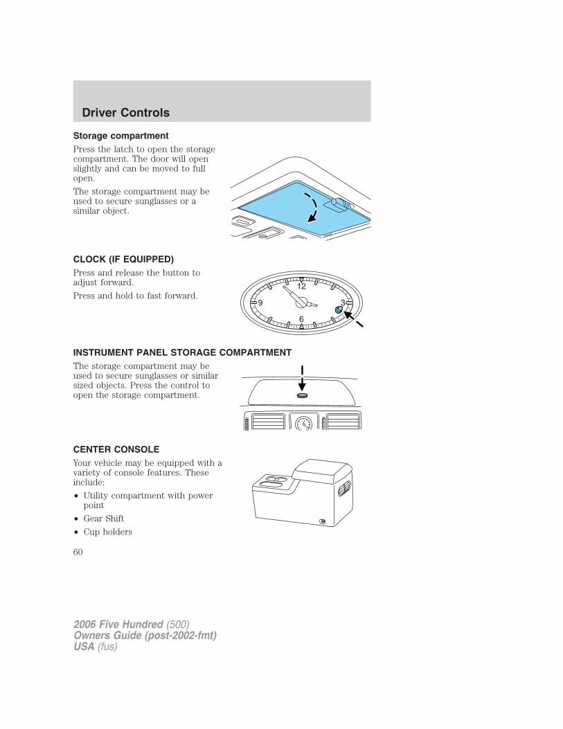
Storage compartmentPress the latch to open the storagecompartment. The door will openslightly and can be moved to fullopen.
The storage compartment may beused to secure sunglasses or asimilar object.
CLOCK (IF EQUIPPED)Press and release the button toadjust forward.
Press and hold to fast forward.
INSTRUMENT PANEL STORAGE COMPARTMENTThe storage compartment may beused to secure sunglasses or similarsized objects. Press the control toopen the storage compartment.
CENTER CONSOLEYour vehicle may be equipped with avariety of console features. Theseinclude:
• Utility compartment with powerpoint
• Gear Shift
• Cup holders
2006 Five Hundred (500)Owners Guide (post-2002-fmt)USA (fus)
Driver Controls
60
• Rear vent (if equipped)
Use only soft cups in the cupholder. Hard objects can injure youin a collision.
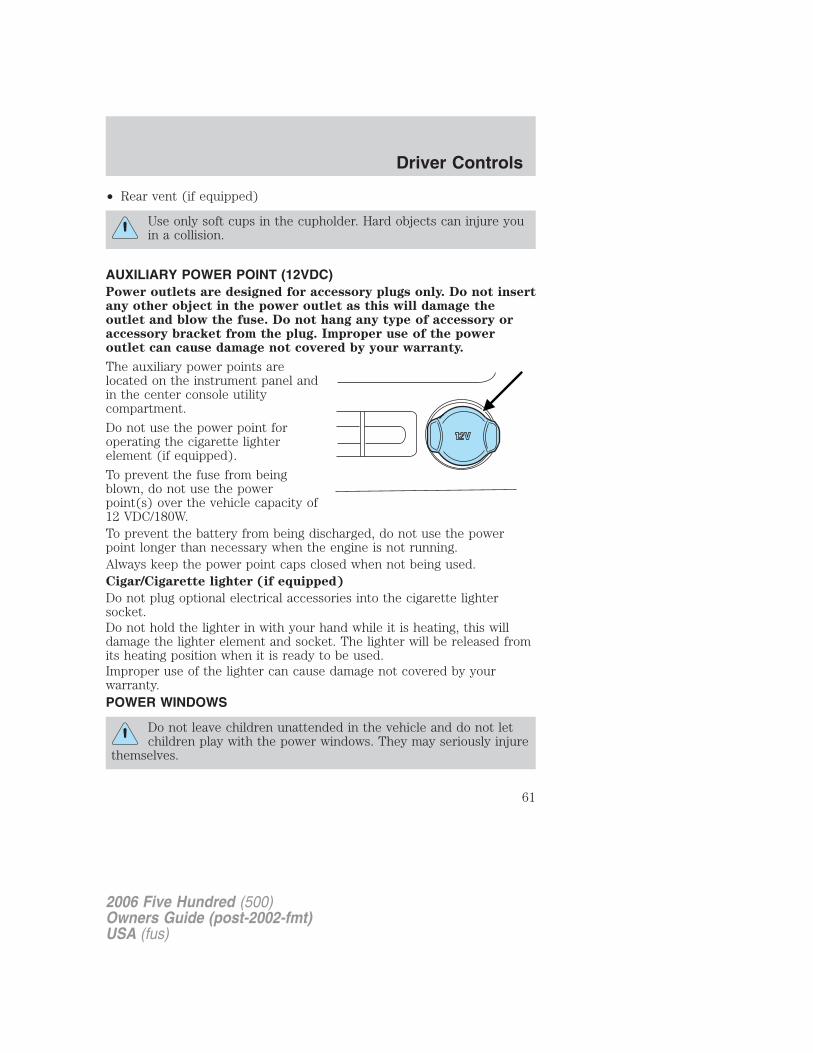
AUXILIARY POWER POINT (12VDC)Power outlets are designed for accessory plugs only. Do not insertany other object in the power outlet as this will damage theoutlet and blow the fuse. Do not hang any type of accessory oraccessory bracket from the plug. Improper use of the poweroutlet can cause damage not covered by your warranty.
The auxiliary power points arelocated on the instrument panel andin the center console utilitycompartment.
Do not use the power point foroperating the cigarette lighterelement (if equipped).
To prevent the fuse from beingblown, do not use the powerpoint(s) over the vehicle capacity of12 VDC/180W.To prevent the battery from being discharged, do not use the powerpoint longer than necessary when the engine is not running.Always keep the power point caps closed when not being used.Cigar/Cigarette lighter (if equipped)
Do not plug optional electrical accessories into the cigarette lightersocket.Do not hold the lighter in with your hand while it is heating, this willdamage the lighter element and socket. The lighter will be released fromits heating position when it is ready to be used.Improper use of the lighter can cause damage not covered by yourwarranty.POWER WINDOWS
Do not leave children unattended in the vehicle and do not letchildren play with the power windows. They may seriously injure
themselves.
2006 Five Hundred (500)Owners Guide (post-2002-fmt)USA (fus)
Driver Controls
61
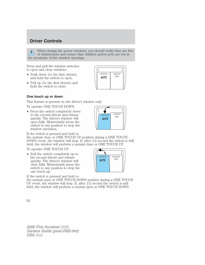
When closing the power windows, you should verify they are freeof obstructions and ensure that children and/or pets are not in
the proximity of the window openings.
Press and pull the window switchesto open and close windows.
• Push down (to the first detent)and hold the switch to open.
• Pull up (to the first detent) andhold the switch to close.
One touch up or down
This feature is present on the driver’s window only.
To operate ONE TOUCH DOWN:
• Press the switch completely downto the second detent and releasequickly. The driver’s window willopen fully. Momentarily press theswitch to any position to stop thewindow operation.
If the switch is pressed and held tothe normal close or ONE TOUCH UP position during a ONE TOUCHDOWN event, the window will stop. If, after 1/2 second the switch is stillheld, the window will perform a normal close or ONE TOUCH UP.
To operate ONE TOUCH UP:
• Pull the switch completely up tothe second detent and releasequickly. The driver’s window willclose fully. Momentarily press theswitch to any position to stop theone touch up.
If the switch is pressed and held tothe normal open or ONE TOUCH DOWN position during a ONE TOUCHUP event, the window will stop. If, after 1/2 second the switch is stillheld, the window will perform a normal open or ONE TOUCH DOWN.
AUTO
2006 Five Hundred (500)Owners Guide (post-2002-fmt)USA (fus)
Driver Controls
62
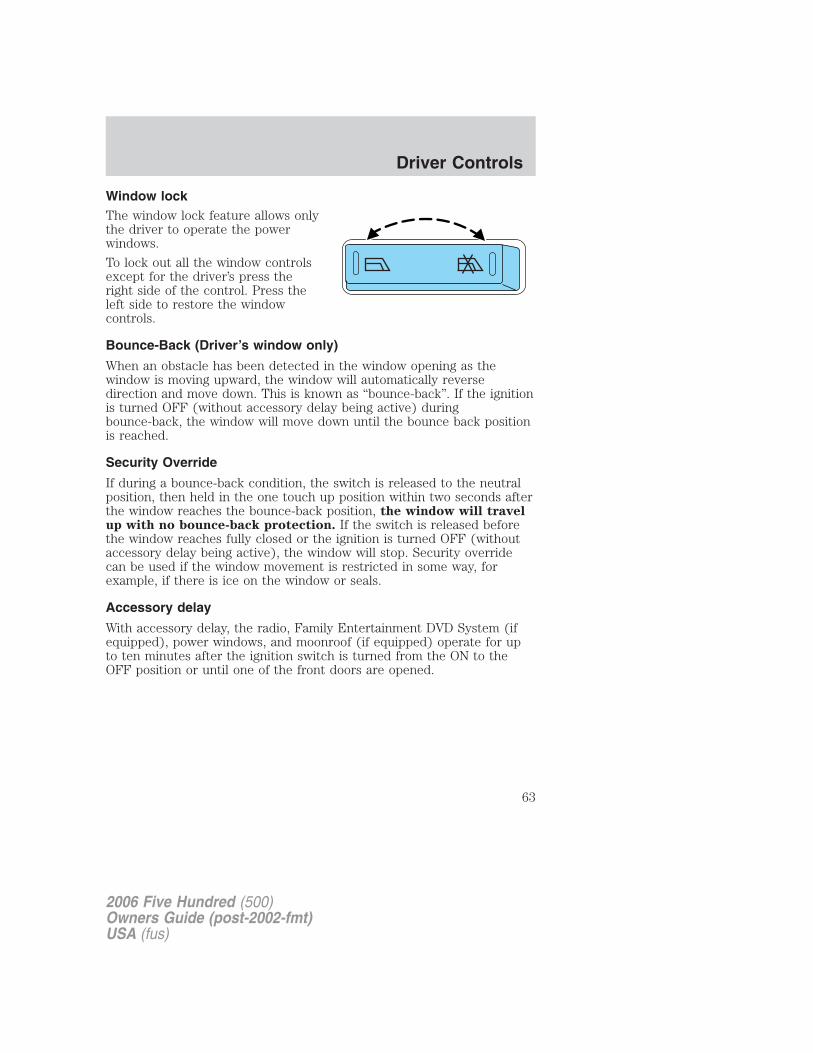
Window lockThe window lock feature allows onlythe driver to operate the powerwindows.
To lock out all the window controlsexcept for the driver’s press theright side of the control. Press theleft side to restore the windowcontrols.
Bounce-Back (Driver’s window only)
When an obstacle has been detected in the window opening as thewindow is moving upward, the window will automatically reversedirection and move down. This is known as “bounce-back”. If the ignitionis turned OFF (without accessory delay being active) duringbounce-back, the window will move down until the bounce back positionis reached.
Security Override
If during a bounce-back condition, the switch is released to the neutralposition, then held in the one touch up position within two seconds afterthe window reaches the bounce-back position, the window will travelup with no bounce-back protection. If the switch is released beforethe window reaches fully closed or the ignition is turned OFF (withoutaccessory delay being active), the window will stop. Security overridecan be used if the window movement is restricted in some way, forexample, if there is ice on the window or seals.
Accessory delay
With accessory delay, the radio, Family Entertainment DVD System (ifequipped), power windows, and moonroof (if equipped) operate for upto ten minutes after the ignition switch is turned from the ON to theOFF position or until one of the front doors are opened.
2006 Five Hundred (500)Owners Guide (post-2002-fmt)USA (fus)
Driver Controls
63
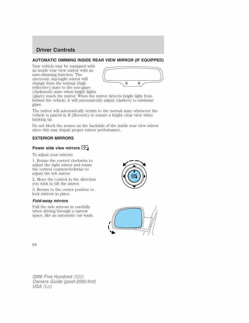
AUTOMATIC DIMMING INSIDE REAR VIEW MIRROR (IF EQUIPPED)Your vehicle may be equipped withan inside rear view mirror with anauto-dimming function. Theelectronic day/night mirror willchange from the normal (highreflective) state to the non-glare(darkened) state when bright lights(glare) reach the mirror. When the mirror detects bright light frombehind the vehicle, it will automatically adjust (darken) to minimizeglare.
The mirror will automatically return to the normal state whenever thevehicle is placed in R (Reverse) to ensure a bright clear view whenbacking up.
Do not block the sensor on the backside of the inside rear view mirrorsince this may impair proper mirror performance.
EXTERIOR MIRRORS
Power side view mirrors
To adjust your mirrors:
1. Rotate the control clockwise toadjust the right mirror and rotatethe control counterclockwise toadjust the left mirror.
2. Move the control in the directionyou wish to tilt the mirror.
3. Return to the center position tolock mirrors in place.
Fold-away mirrorsPull the side mirrors in carefullywhen driving through a narrowspace, like an automatic car wash.
2006 Five Hundred (500)Owners Guide (post-2002-fmt)USA (fus)
Driver Controls
64
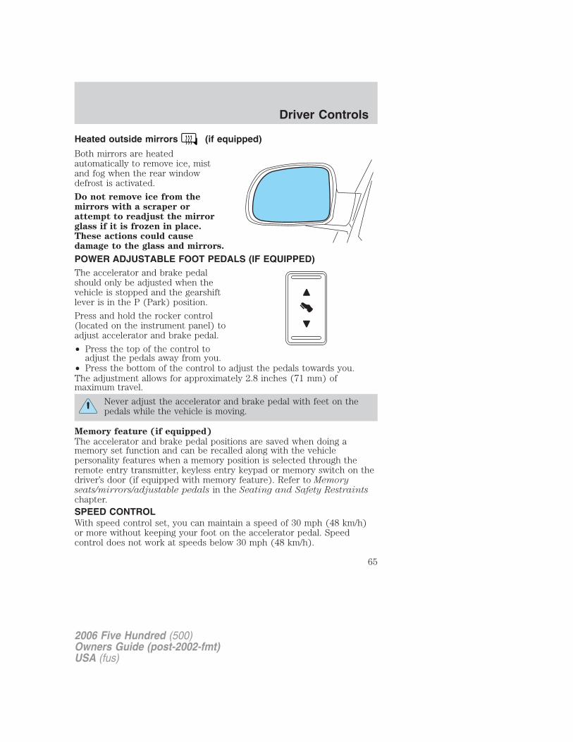
Heated outside mirrors (if equipped)
Both mirrors are heatedautomatically to remove ice, mistand fog when the rear windowdefrost is activated.
Do not remove ice from themirrors with a scraper orattempt to readjust the mirrorglass if it is frozen in place.These actions could causedamage to the glass and mirrors.
POWER ADJUSTABLE FOOT PEDALS (IF EQUIPPED)The accelerator and brake pedalshould only be adjusted when thevehicle is stopped and the gearshiftlever is in the P (Park) position.
Press and hold the rocker control(located on the instrument panel) toadjust accelerator and brake pedal.
• Press the top of the control toadjust the pedals away from you.
• Press the bottom of the control to adjust the pedals towards you.The adjustment allows for approximately 2.8 inches (71 mm) ofmaximum travel.
Never adjust the accelerator and brake pedal with feet on thepedals while the vehicle is moving.
Memory feature (if equipped)
The accelerator and brake pedal positions are saved when doing amemory set function and can be recalled along with the vehiclepersonality features when a memory position is selected through theremote entry transmitter, keyless entry keypad or memory switch on thedriver’s door (if equipped with memory feature). Refer to Memoryseats/mirrors/adjustable pedals in the Seating and Safety Restraintschapter.SPEED CONTROLWith speed control set, you can maintain a speed of 30 mph (48 km/h)or more without keeping your foot on the accelerator pedal. Speedcontrol does not work at speeds below 30 mph (48 km/h).
2006 Five Hundred (500)Owners Guide (post-2002-fmt)USA (fus)
Driver Controls
65
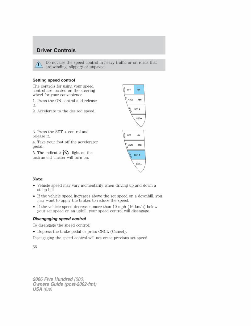
Do not use the speed control in heavy traffic or on roads thatare winding, slippery or unpaved.
Setting speed controlThe controls for using your speedcontrol are located on the steeringwheel for your convenience.
1. Press the ON control and releaseit.
2. Accelerate to the desired speed.
3. Press the SET + control andrelease it.
4. Take your foot off the acceleratorpedal.
5. The indicator light on theinstrument cluster will turn on.
Note:
• Vehicle speed may vary momentarily when driving up and down asteep hill.
• If the vehicle speed increases above the set speed on a downhill, youmay want to apply the brakes to reduce the speed.
• If the vehicle speed decreases more than 10 mph (16 km/h) belowyour set speed on an uphill, your speed control will disengage.
Disengaging speed control
To disengage the speed control:
• Depress the brake pedal or press CNCL (Cancel).
Disengaging the speed control will not erase previous set speed.
SET
SET
RSMCNCL
ONOFF
SET
SET
RSMCNCL
ONOFF
2006 Five Hundred (500)Owners Guide (post-2002-fmt)USA (fus)
Driver Controls
66
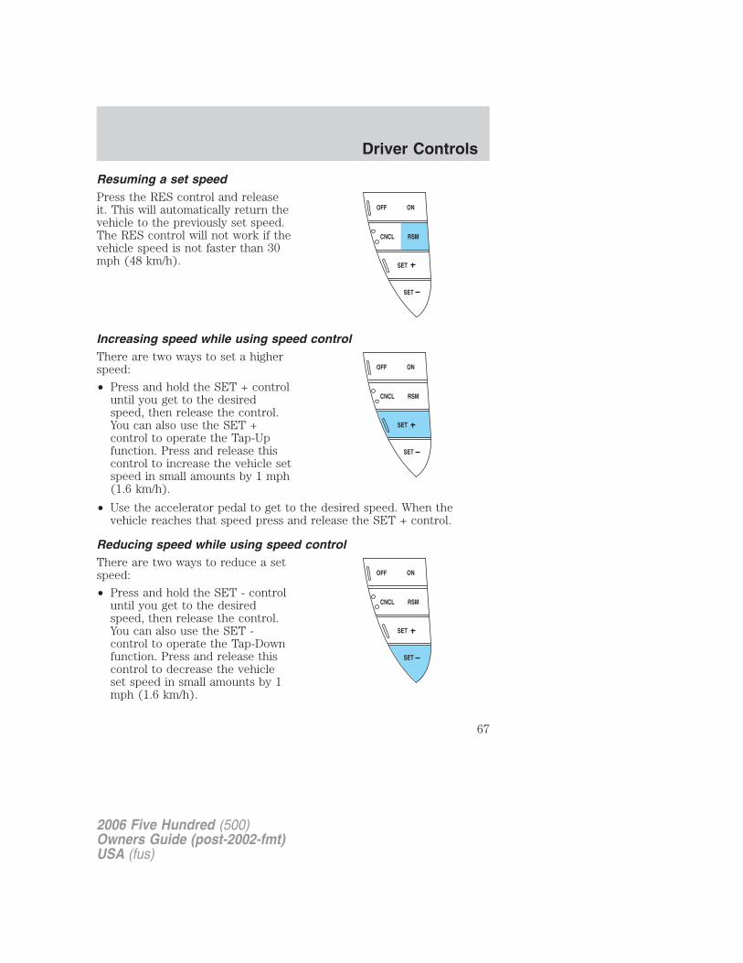
Resuming a set speedPress the RES control and releaseit. This will automatically return thevehicle to the previously set speed.The RES control will not work if thevehicle speed is not faster than 30mph (48 km/h).
Increasing speed while using speed controlThere are two ways to set a higherspeed:
• Press and hold the SET + controluntil you get to the desiredspeed, then release the control.You can also use the SET +control to operate the Tap-Upfunction. Press and release thiscontrol to increase the vehicle setspeed in small amounts by 1 mph(1.6 km/h).
• Use the accelerator pedal to get to the desired speed. When thevehicle reaches that speed press and release the SET + control.
Reducing speed while using speed controlThere are two ways to reduce a setspeed:
• Press and hold the SET - controluntil you get to the desiredspeed, then release the control.You can also use the SET -control to operate the Tap-Downfunction. Press and release thiscontrol to decrease the vehicleset speed in small amounts by 1mph (1.6 km/h).
SET
SET
RSMCNCL
ONOFF
SET
SET
RSMCNCL
ONOFF
SET
SET
RSMCNCL
ONOFF
2006 Five Hundred (500)Owners Guide (post-2002-fmt)USA (fus)
Driver Controls
67
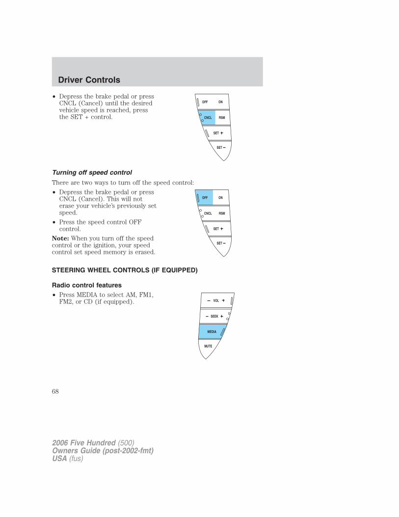
• Depress the brake pedal or pressCNCL (Cancel) until the desiredvehicle speed is reached, pressthe SET + control.
Turning off speed control
There are two ways to turn off the speed control:
• Depress the brake pedal or pressCNCL (Cancel). This will noterase your vehicle’s previously setspeed.
• Press the speed control OFFcontrol.
Note: When you turn off the speedcontrol or the ignition, your speedcontrol set speed memory is erased.
STEERING WHEEL CONTROLS (IF EQUIPPED)
Radio control features• Press MEDIA to select AM, FM1,
FM2, or CD (if equipped).
SET
SET
RSMCNCL
ONOFF
SET
SET
RSMCNCL
ONOFF
MUTE
MEDIA
SEEK
VOL
2006 Five Hundred (500)Owners Guide (post-2002-fmt)USA (fus)
Driver Controls
68
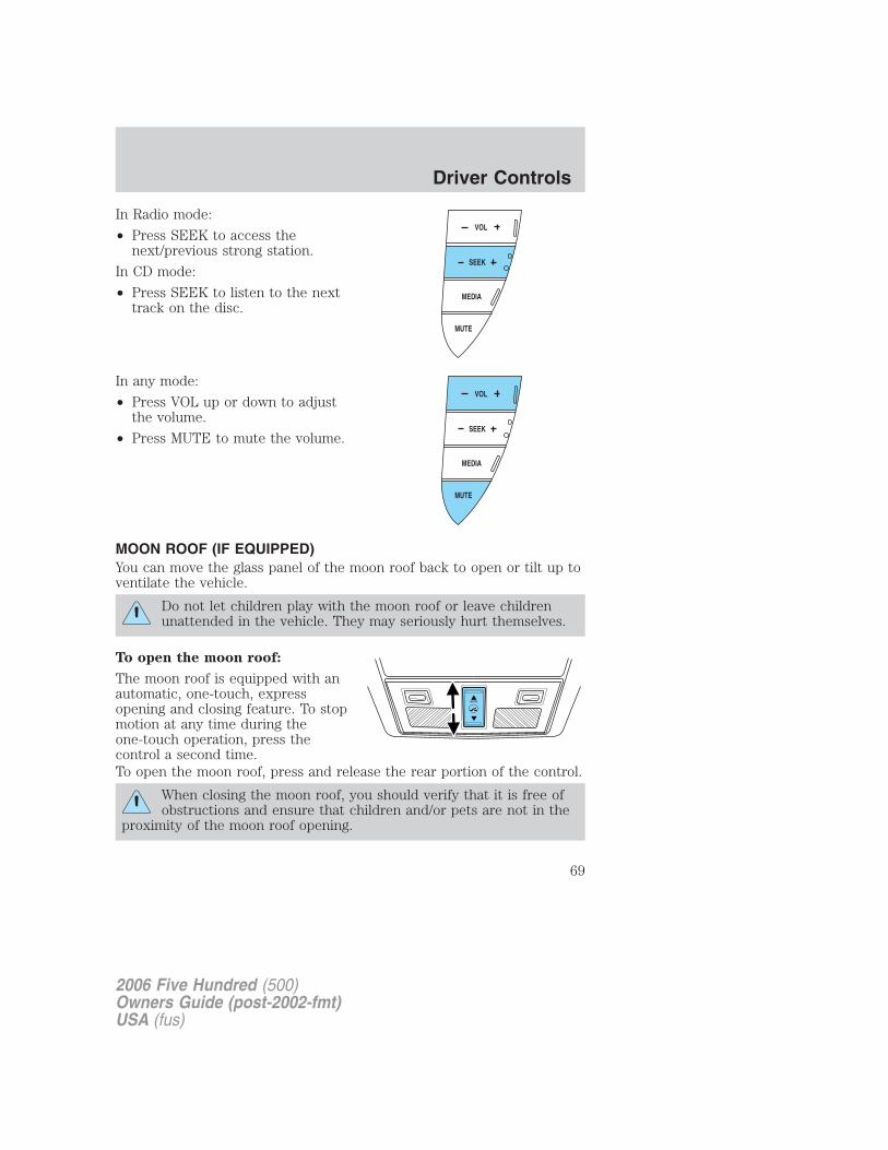
In Radio mode:
• Press SEEK to access thenext/previous strong station.
In CD mode:
• Press SEEK to listen to the nexttrack on the disc.
In any mode:
• Press VOL up or down to adjustthe volume.
• Press MUTE to mute the volume.
MOON ROOF (IF EQUIPPED)You can move the glass panel of the moon roof back to open or tilt up toventilate the vehicle.
Do not let children play with the moon roof or leave childrenunattended in the vehicle. They may seriously hurt themselves.
To open the moon roof:
The moon roof is equipped with anautomatic, one-touch, expressopening and closing feature. To stopmotion at any time during theone-touch operation, press thecontrol a second time.To open the moon roof, press and release the rear portion of the control.
When closing the moon roof, you should verify that it is free ofobstructions and ensure that children and/or pets are not in the
proximity of the moon roof opening.
MUTE
MEDIA
SEEK
VOL
2006 Five Hundred (500)Owners Guide (post-2002-fmt)USA (fus)
Driver Controls
69
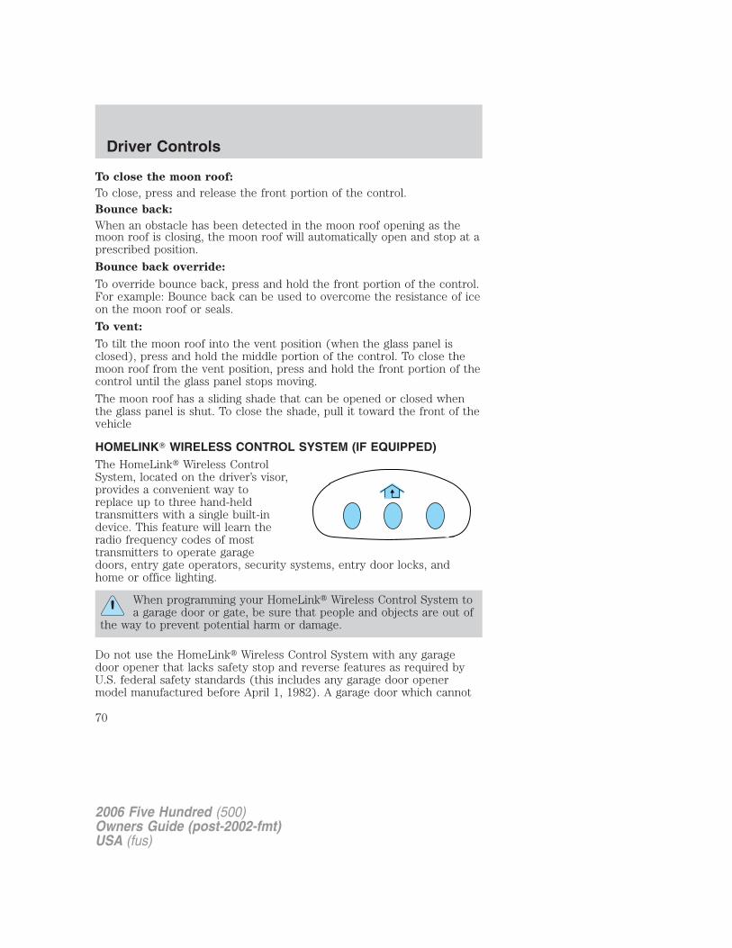
To close the moon roof:
To close, press and release the front portion of the control.Bounce back:
When an obstacle has been detected in the moon roof opening as themoon roof is closing, the moon roof will automatically open and stop at aprescribed position.
Bounce back override:
To override bounce back, press and hold the front portion of the control.For example: Bounce back can be used to overcome the resistance of iceon the moon roof or seals.
To vent:
To tilt the moon roof into the vent position (when the glass panel isclosed), press and hold the middle portion of the control. To close themoon roof from the vent position, press and hold the front portion of thecontrol until the glass panel stops moving.
The moon roof has a sliding shade that can be opened or closed whenthe glass panel is shut. To close the shade, pull it toward the front of thevehicle
HOMELINK� WIRELESS CONTROL SYSTEM (IF EQUIPPED)The HomeLink� Wireless ControlSystem, located on the driver’s visor,provides a convenient way toreplace up to three hand-heldtransmitters with a single built-indevice. This feature will learn theradio frequency codes of mosttransmitters to operate garagedoors, entry gate operators, security systems, entry door locks, andhome or office lighting.
When programming your HomeLink� Wireless Control System toa garage door or gate, be sure that people and objects are out of
the way to prevent potential harm or damage.
Do not use the HomeLink� Wireless Control System with any garagedoor opener that lacks safety stop and reverse features as required byU.S. federal safety standards (this includes any garage door openermodel manufactured before April 1, 1982). A garage door which cannot
2006 Five Hundred (500)Owners Guide (post-2002-fmt)USA (fus)
Driver Controls
70
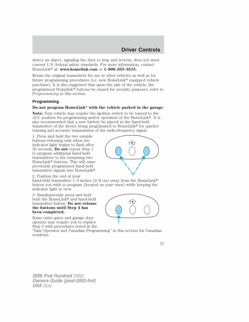
detect an object, signaling the door to stop and reverse, does not meetcurrent U.S. federal safety standards. For more information, contactHomeLink� at: www.homelink.com or 1–800–355–3515.
Retain the original transmitter for use in other vehicles as well as forfuture programming procedures (i.e. new HomeLink� equipped vehiclepurchase). It is also suggested that upon the sale of the vehicle, theprogrammed Homelink� buttons be erased for security purposes, refer toProgramming in this section.
ProgrammingDo not program HomeLink� with the vehicle parked in the garage.
Note: Your vehicle may require the ignition switch to be turned to theACC position for programming and/or operation of the HomeLink�. It isalso recommended that a new battery be placed in the hand-heldtransmitter of the device being programmed to HomeLink� for quickertraining and accurate transmission of the radio-frequency signal.
1. Press and hold the two outsidebuttons releasing only when theindicator light begins to flash after20 seconds. Do not repeat Step 1to program additional hand-heldtransmitters to the remaining twoHomeLink� buttons. This will erasepreviously programmed hand-heldtransmitter signals into HomeLink�.
2. Position the end of yourhand-held transmitter 1–3 inches (2–8 cm) away from the HomeLink�button you wish to program (located on your visor) while keeping theindicator light in view.
3. Simultaneously press and holdboth the HomeLink� and hand-heldtransmitter button. Do not releasethe buttons until Step 4 hasbeen completed.
Some entry gates and garage dooropeners may require you to replaceStep 3 with procedures noted in the“Gate Operator and Canadian Programming” in this section for Canadianresidents.
2006 Five Hundred (500)Owners Guide (post-2002-fmt)USA (fus)
Driver Controls
71
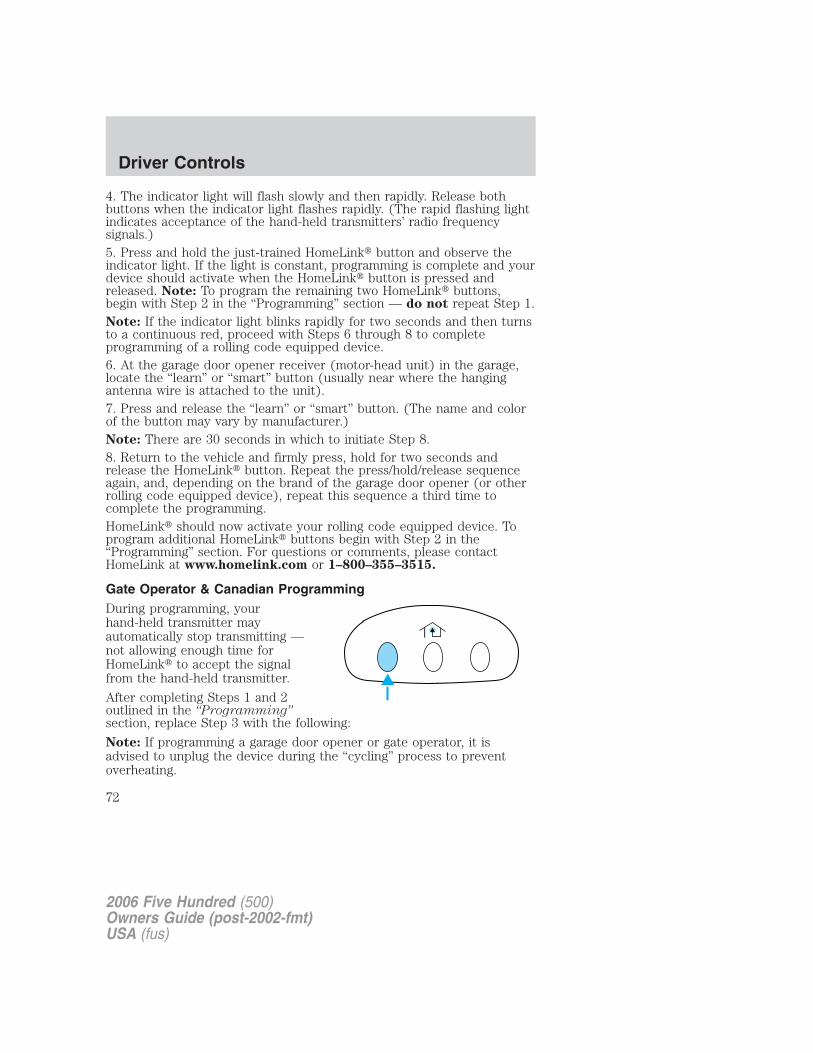
4. The indicator light will flash slowly and then rapidly. Release bothbuttons when the indicator light flashes rapidly. (The rapid flashing lightindicates acceptance of the hand-held transmitters’ radio frequencysignals.)5. Press and hold the just-trained HomeLink� button and observe theindicator light. If the light is constant, programming is complete and yourdevice should activate when the HomeLink� button is pressed andreleased. Note: To program the remaining two HomeLink� buttons,begin with Step 2 in the “Programming” section — do not repeat Step 1.Note: If the indicator light blinks rapidly for two seconds and then turnsto a continuous red, proceed with Steps 6 through 8 to completeprogramming of a rolling code equipped device.6. At the garage door opener receiver (motor-head unit) in the garage,locate the “learn” or “smart” button (usually near where the hangingantenna wire is attached to the unit).7. Press and release the “learn” or “smart” button. (The name and colorof the button may vary by manufacturer.)Note: There are 30 seconds in which to initiate Step 8.8. Return to the vehicle and firmly press, hold for two seconds andrelease the HomeLink� button. Repeat the press/hold/release sequenceagain, and, depending on the brand of the garage door opener (or otherrolling code equipped device), repeat this sequence a third time tocomplete the programming.HomeLink� should now activate your rolling code equipped device. Toprogram additional HomeLink� buttons begin with Step 2 in the“Programming” section. For questions or comments, please contactHomeLink at www.homelink.com or 1–800–355–3515.
Gate Operator & Canadian ProgrammingDuring programming, yourhand-held transmitter mayautomatically stop transmitting —not allowing enough time forHomeLink� to accept the signalfrom the hand-held transmitter.
After completing Steps 1 and 2outlined in the “Programming”section, replace Step 3 with the following:
Note: If programming a garage door opener or gate operator, it isadvised to unplug the device during the “cycling” process to preventoverheating.
2006 Five Hundred (500)Owners Guide (post-2002-fmt)USA (fus)
Driver Controls
72
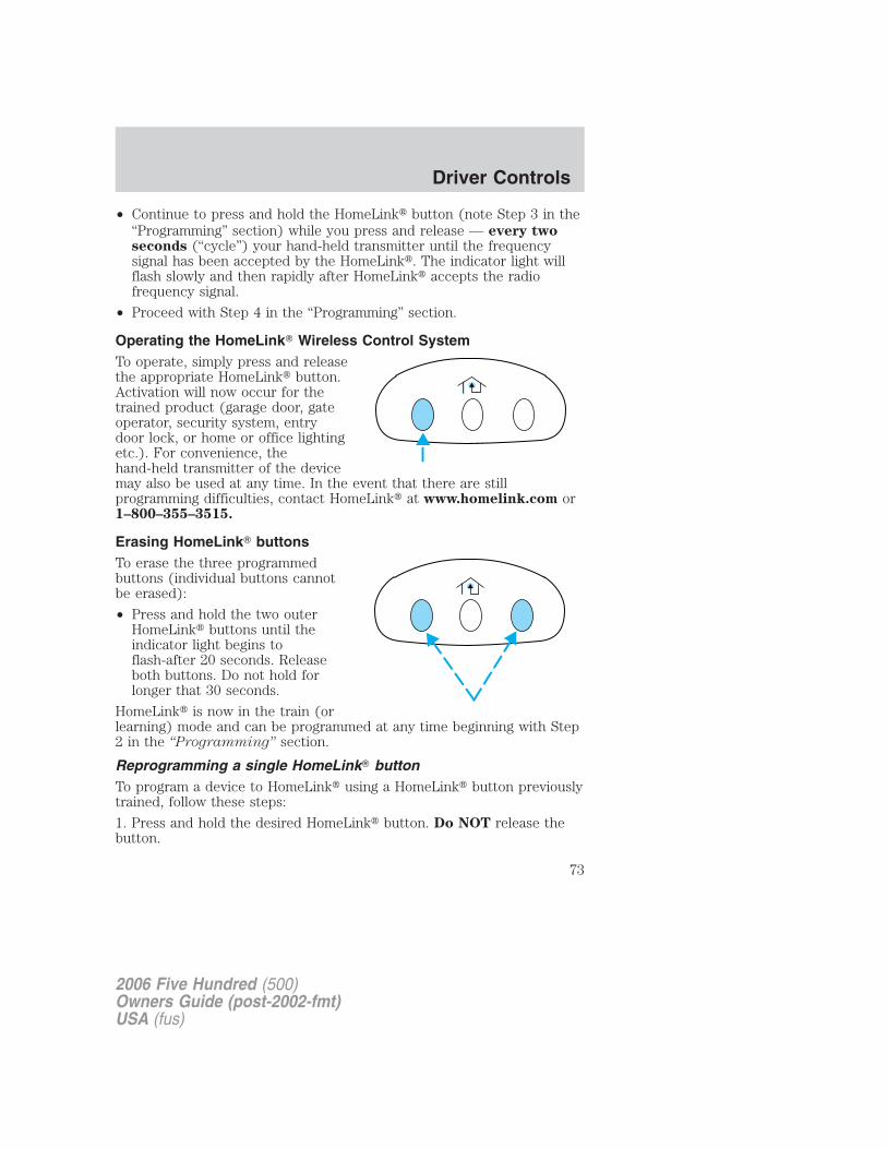
• Continue to press and hold the HomeLink� button (note Step 3 in the“Programming” section) while you press and release — every twoseconds (“cycle”) your hand-held transmitter until the frequencysignal has been accepted by the HomeLink�. The indicator light willflash slowly and then rapidly after HomeLink� accepts the radiofrequency signal.
• Proceed with Step 4 in the “Programming” section.
Operating the HomeLink� Wireless Control SystemTo operate, simply press and releasethe appropriate HomeLink� button.Activation will now occur for thetrained product (garage door, gateoperator, security system, entrydoor lock, or home or office lightingetc.). For convenience, thehand-held transmitter of the devicemay also be used at any time. In the event that there are stillprogramming difficulties, contact HomeLink� at www.homelink.com or1–800–355–3515.
Erasing HomeLink� buttonsTo erase the three programmedbuttons (individual buttons cannotbe erased):
• Press and hold the two outerHomeLink� buttons until theindicator light begins toflash-after 20 seconds. Releaseboth buttons. Do not hold forlonger that 30 seconds.
HomeLink� is now in the train (orlearning) mode and can be programmed at any time beginning with Step2 in the “Programming” section.
Reprogramming a single HomeLink� buttonTo program a device to HomeLink� using a HomeLink� button previouslytrained, follow these steps:
1. Press and hold the desired HomeLink� button. Do NOT release thebutton.
2006 Five Hundred (500)Owners Guide (post-2002-fmt)USA (fus)
Driver Controls
73
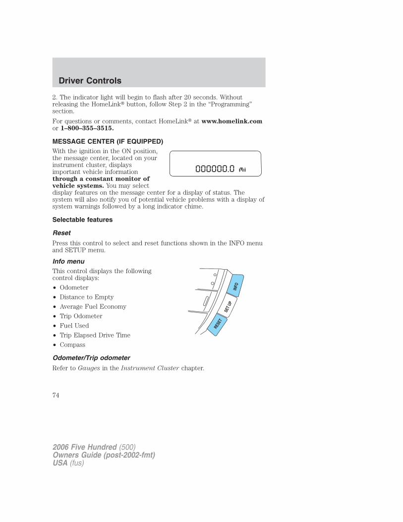
2. The indicator light will begin to flash after 20 seconds. Withoutreleasing the HomeLink� button, follow Step 2 in the “Programming”section.
For questions or comments, contact HomeLink� at www.homelink.comor 1–800–355–3515.
MESSAGE CENTER (IF EQUIPPED)With the ignition in the ON position,the message center, located on yourinstrument cluster, displaysimportant vehicle informationthrough a constant monitor ofvehicle systems. You may selectdisplay features on the message center for a display of status. Thesystem will also notify you of potential vehicle problems with a display ofsystem warnings followed by a long indicator chime.
Selectable features
Reset
Press this control to select and reset functions shown in the INFO menuand SETUP menu.
Info menuThis control displays the followingcontrol displays:
• Odometer
• Distance to Empty
• Average Fuel Economy
• Trip Odometer
• Fuel Used
• Trip Elapsed Drive Time
• Compass
Odometer/Trip odometer
Refer to Gauges in the Instrument Cluster chapter.
2006 Five Hundred (500)Owners Guide (post-2002-fmt)USA (fus)
Driver Controls
74
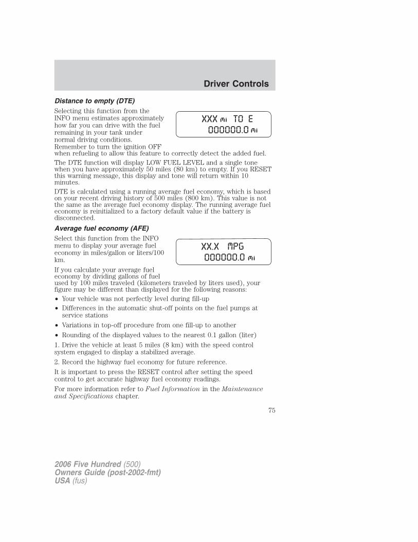
Distance to empty (DTE)Selecting this function from theINFO menu estimates approximatelyhow far you can drive with the fuelremaining in your tank undernormal driving conditions.Remember to turn the ignition OFFwhen refueling to allow this feature to correctly detect the added fuel.The DTE function will display LOW FUEL LEVEL and a single tonewhen you have approximately 50 miles (80 km) to empty. If you RESETthis warning message, this display and tone will return within 10minutes.DTE is calculated using a running average fuel economy, which is basedon your recent driving history of 500 miles (800 km). This value is notthe same as the average fuel economy display. The running average fueleconomy is reinitialized to a factory default value if the battery isdisconnected.
Average fuel economy (AFE)Select this function from the INFOmenu to display your average fueleconomy in miles/gallon or liters/100km.
If you calculate your average fueleconomy by dividing gallons of fuelused by 100 miles traveled (kilometers traveled by liters used), yourfigure may be different than displayed for the following reasons:• Your vehicle was not perfectly level during fill-up• Differences in the automatic shut-off points on the fuel pumps at
service stations
• Variations in top-off procedure from one fill-up to another
• Rounding of the displayed values to the nearest 0.1 gallon (liter)
1. Drive the vehicle at least 5 miles (8 km) with the speed controlsystem engaged to display a stabilized average.
2. Record the highway fuel economy for future reference.
It is important to press the RESET control after setting the speedcontrol to get accurate highway fuel economy readings.
For more information refer to Fuel Information in the Maintenanceand Specifications chapter.
2006 Five Hundred (500)Owners Guide (post-2002-fmt)USA (fus)
Driver Controls
75
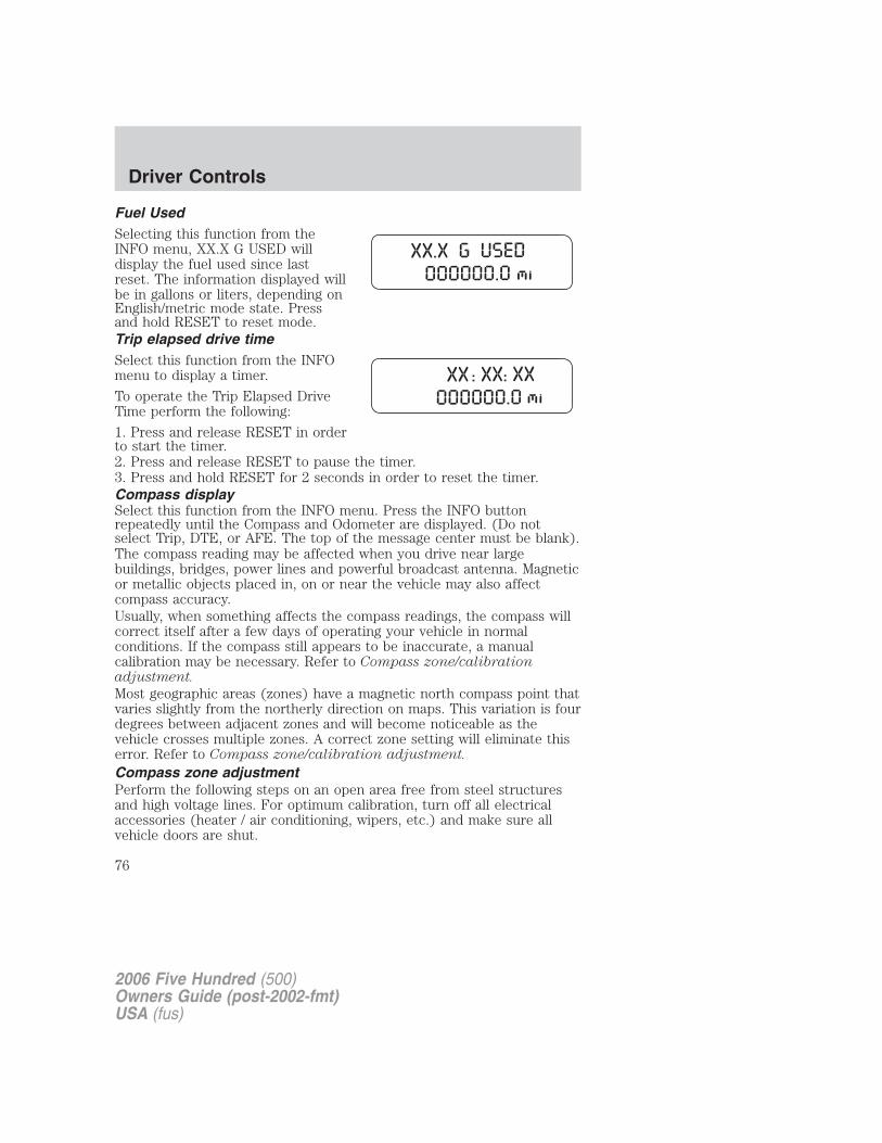
Fuel UsedSelecting this function from theINFO menu, XX.X G USED willdisplay the fuel used since lastreset. The information displayed willbe in gallons or liters, depending onEnglish/metric mode state. Pressand hold RESET to reset mode.Trip elapsed drive timeSelect this function from the INFOmenu to display a timer.
To operate the Trip Elapsed DriveTime perform the following:
1. Press and release RESET in orderto start the timer.2. Press and release RESET to pause the timer.3. Press and hold RESET for 2 seconds in order to reset the timer.Compass displaySelect this function from the INFO menu. Press the INFO buttonrepeatedly until the Compass and Odometer are displayed. (Do notselect Trip, DTE, or AFE. The top of the message center must be blank).The compass reading may be affected when you drive near largebuildings, bridges, power lines and powerful broadcast antenna. Magneticor metallic objects placed in, on or near the vehicle may also affectcompass accuracy.Usually, when something affects the compass readings, the compass willcorrect itself after a few days of operating your vehicle in normalconditions. If the compass still appears to be inaccurate, a manualcalibration may be necessary. Refer to Compass zone/calibrationadjustment.
Most geographic areas (zones) have a magnetic north compass point thatvaries slightly from the northerly direction on maps. This variation is fourdegrees between adjacent zones and will become noticeable as thevehicle crosses multiple zones. A correct zone setting will eliminate thiserror. Refer to Compass zone/calibration adjustment.
Compass zone adjustmentPerform the following steps on an open area free from steel structuresand high voltage lines. For optimum calibration, turn off all electricalaccessories (heater / air conditioning, wipers, etc.) and make sure allvehicle doors are shut.
2006 Five Hundred (500)Owners Guide (post-2002-fmt)USA (fus)
Driver Controls
76
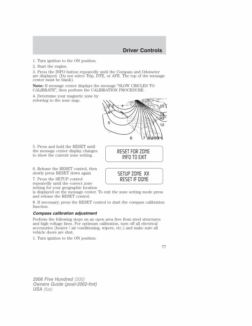
1. Turn ignition to the ON position.2. Start the engine.3. Press the INFO button repeatedly until the Compass and Odometerare displayed. (Do not select Trip, DTE, or AFE. The top of the messagecenter must be blank).
Note: If message center displays the message �SLOW CIRCLES TOCALIBRATE�, then perform the CALIBRATION PROCEDURE.
4. Determine your magnetic zone byreferring to the zone map.
5. Press and hold the RESET untilthe message center display changesto show the current zone setting.
6. Release the RESET control, thenslowly press RESET down again.
7. Press the SETUP controlrepeatedly until the correct zonesetting for your geographic locationis displayed on the message center. To exit the zone setting mode pressand release the RESET control.
8. If necessary, press the RESET control to start the compass calibrationfunction.
Compass calibration adjustmentPerform the following steps on an open area free from steel structuresand high voltage lines. For optimum calibration, turn off all electricalaccessories (heater / air conditioning, wipers, etc.) and make sure allvehicle doors are shut.
1. Turn ignition to the ON position.
123
4
5
6 7 8 91011
12
1314
15
2006 Five Hundred (500)Owners Guide (post-2002-fmt)USA (fus)
Driver Controls
77
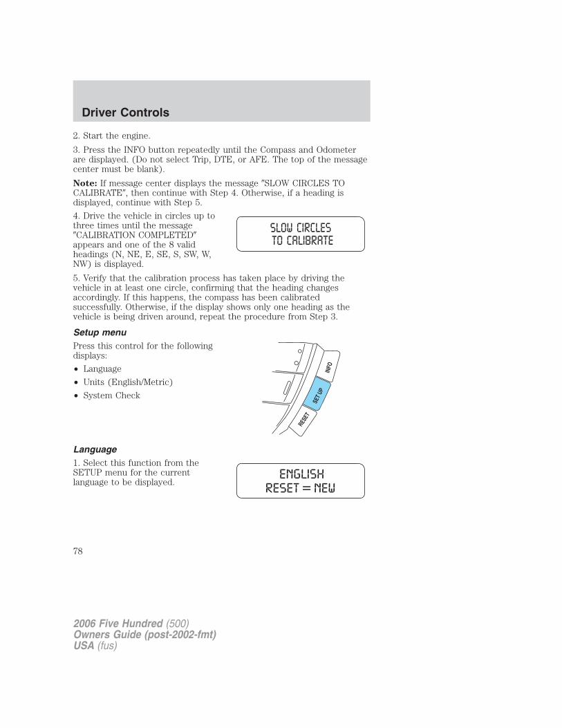
2. Start the engine.
3. Press the INFO button repeatedly until the Compass and Odometerare displayed. (Do not select Trip, DTE, or AFE. The top of the messagecenter must be blank).
Note: If message center displays the message �SLOW CIRCLES TOCALIBRATE�, then continue with Step 4. Otherwise, if a heading isdisplayed, continue with Step 5.
4. Drive the vehicle in circles up tothree times until the message�CALIBRATION COMPLETED�appears and one of the 8 validheadings (N, NE, E, SE, S, SW, W,NW) is displayed.
5. Verify that the calibration process has taken place by driving thevehicle in at least one circle, confirming that the heading changesaccordingly. If this happens, the compass has been calibratedsuccessfully. Otherwise, if the display shows only one heading as thevehicle is being driven around, repeat the procedure from Step 3.
Setup menuPress this control for the followingdisplays:
• Language
• Units (English/Metric)
• System Check
Language1. Select this function from theSETUP menu for the currentlanguage to be displayed.
2006 Five Hundred (500)Owners Guide (post-2002-fmt)USA (fus)
Driver Controls
78
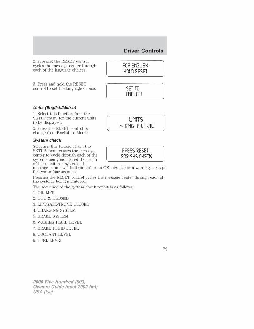
2. Pressing the RESET controlcycles the message center througheach of the language choices.
3. Press and hold the RESETcontrol to set the language choice.
Units (English/Metric)1. Select this function from theSETUP menu for the current unitsto be displayed.
2. Press the RESET control tochange from English to Metric.
System checkSelecting this function from theSETUP menu causes the messagecenter to cycle through each of thesystems being monitored. For eachof the monitored systems, themessage center will indicate either an OK message or a warning messagefor two to four seconds.Pressing the RESET control cycles the message center through each ofthe systems being monitored.The sequence of the system check report is as follows:1. OIL LIFE2. DOORS CLOSED
3. LIFTGATE/TRUNK CLOSED
4. CHARGING SYSTEM
5. BRAKE SYSTEM
6. WASHER FLUID LEVEL
7. BRAKE FLUID LEVEL
8. COOLANT LEVEL
9. FUEL LEVEL
2006 Five Hundred (500)Owners Guide (post-2002-fmt)USA (fus)
Driver Controls
79
System warningsSystem warnings alert you to possible problems or malfunctions in yourvehicle’s operating systems.
In the event of a multiple warning situation, the message center willcycle the display to show all warnings by displaying each one for severalseconds.
The message center will display the last selected feature if there are nomore warning messages. This allows you to use the full functionality ofthe message center after you acknowledge the warning by pressing theRESET control and clearing the warning message.
Warning messages that have been reset are divided into three categories:
• They will not disappear until a condition is changed.
• They will reappear on the display ten minutes from the reset.
• They will not reappear until an ignition OFF-ON cycle has beencompleted.
This acts as a reminder that these warning conditions still exist withinthe vehicle.
Warnings Status
Driver’s door ajar Warning cannot be reset (CLOSEDOOR TO RESET) will be displayedPassenger door ajar
Left rear door ajarRight rear door ajarPark brake engaged RELEASE PARK BRAKE will be
displayedLow fuel level Warning returns after 10 minutesCheck charging systemCheck brake systemLow brake fluid Warning returns after the ignition key
is turned from OFF to RUNLiftgate ajar (if equipped)Trunk ajar (if equipped)Washer Fluid level lowChange oil soonOil change required
2006 Five Hundred (500)Owners Guide (post-2002-fmt)USA (fus)
Driver Controls
80
DRIVER’S DOOR AJAR. Displayed when the driver’s door is notcompletely closed.PASSENGER DOOR AJAR. Displayed when the passenger side door isnot completely closed.LEFT REAR DOOR AJAR. Displayed when the left rear door is notcompletely closed.RIGHT REAR DOOR AJAR. Displayed when the right rear door is notcompletely closed.PARK BRAKE ENGAGED. Displayed when the park brake is engaged.If the warning stays on after the park brake is off, contact yourauthorized dealer as soon as possible.LOW FUEL LEVEL. Displayed as an early reminder of a low fuelcondition.CHECK CHARGING SYSTEM. Displayed when the electrical system isnot maintaining proper voltage. If you are operating electrical accessorieswhen the engine is idling at a low speed, turn off as many of theelectrical loads as possible. If the warning stays on or comes on when theengine is operating at normal speeds, have the electrical system checkedas soon as possible.
CHECK BRAKE SYSTEM. Displayed when the brake system needsservicing. If the warning stays on or continues to come on, contact yourauthorized dealer as soon as possible.
LOW BRAKE FLUID. Indicates the brake fluid level is low and thebrake system should be inspected immediately. Refer to Brake fluidreservoir in the Maintenance and Specifications chapter.
LIFTGATE AJAR (if equipped). Displayed when the liftgate is notcompletely closed.
TRUNK AJAR (if equipped). Displayed when the trunk is notcompletely closed.
LOW WASHER FLUID LEVEL. Indicates the washer fluid reservoir isless than one quarter full. Check the washer fluid level. Refer toWindshield washer fluid in the Maintenance and Specificationschapter.
CHANGE OIL SOON/OIL CHANGE REQUIRED. Oil Life XX%,CHANGE SOON/OIL LIFE 0%, CHANGE OIL, OIL LIFE XX%, CHANGESOON displayed when the engine oil life remaining is 10 percent andagain when the engine oil life remaining is between 5% and 1%. When oillife left reaches 0%, the OIL LIFE 0%, CHANGE OIL message will bedisplayed.
2006 Five Hundred (500)Owners Guide (post-2002-fmt)USA (fus)
Driver Controls
81
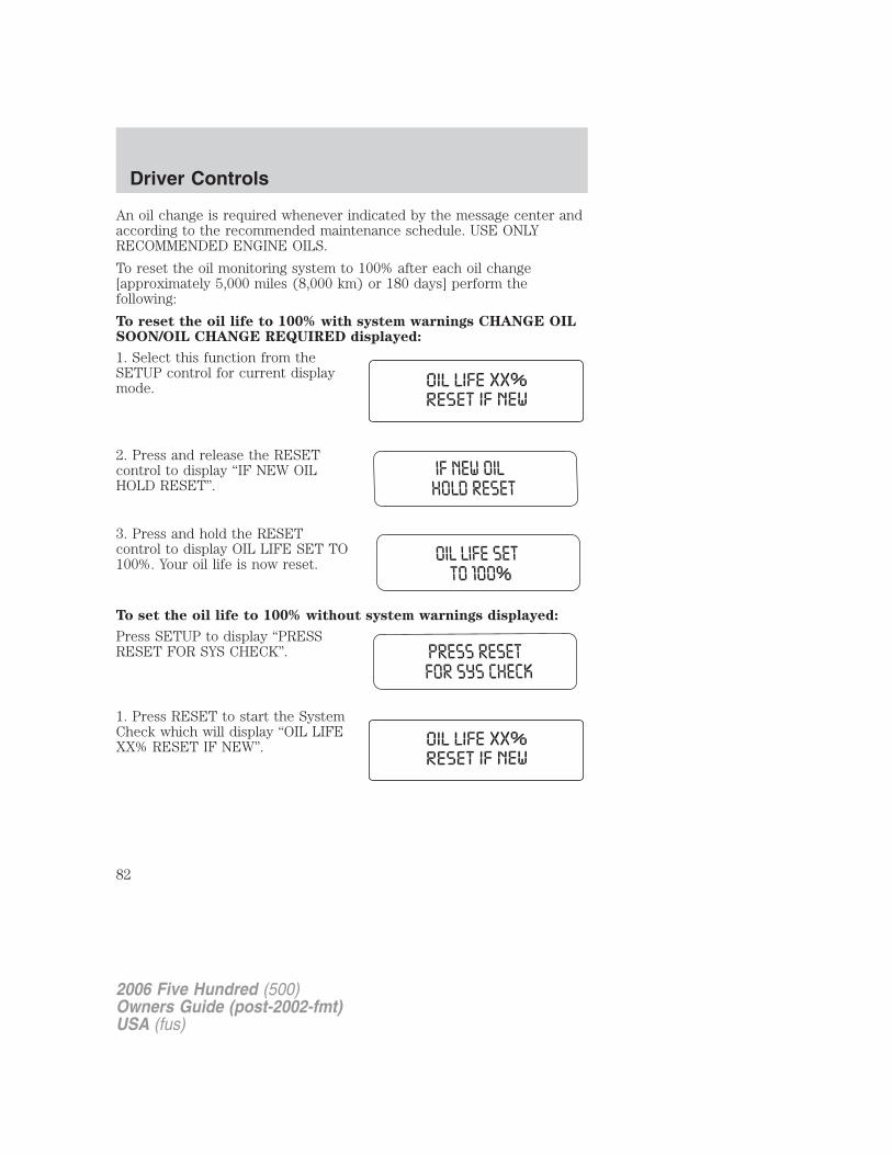
An oil change is required whenever indicated by the message center andaccording to the recommended maintenance schedule. USE ONLYRECOMMENDED ENGINE OILS.
To reset the oil monitoring system to 100% after each oil change[approximately 5,000 miles (8,000 km) or 180 days] perform thefollowing:
To reset the oil life to 100% with system warnings CHANGE OILSOON/OIL CHANGE REQUIRED displayed:
1. Select this function from theSETUP control for current displaymode.
2. Press and release the RESETcontrol to display “IF NEW OILHOLD RESET”.
3. Press and hold the RESETcontrol to display OIL LIFE SET TO100%. Your oil life is now reset.
To set the oil life to 100% without system warnings displayed:
Press SETUP to display “PRESSRESET FOR SYS CHECK”.
1. Press RESET to start the SystemCheck which will display “OIL LIFEXX% RESET IF NEW”.
2006 Five Hundred (500)Owners Guide (post-2002-fmt)USA (fus)
Driver Controls
82
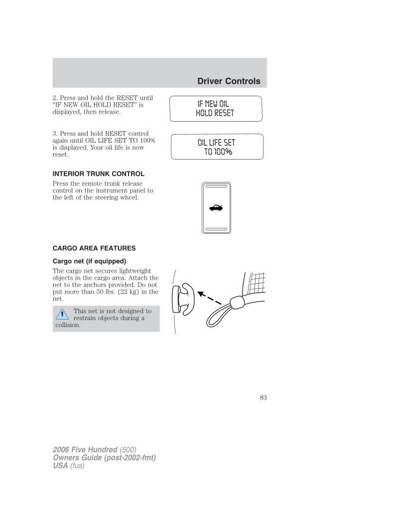
2. Press and hold the RESET until“IF NEW OIL HOLD RESET” isdisplayed, then release.
3. Press and hold RESET controlagain until OIL LIFE SET TO 100%is displayed. Your oil life is nowreset.
INTERIOR TRUNK CONTROLPress the remote trunk releasecontrol on the instrument panel tothe left of the steering wheel.
CARGO AREA FEATURES
Cargo net (if equipped)The cargo net secures lightweightobjects in the cargo area. Attach thenet to the anchors provided. Do notput more than 50 lbs. (22 kg) in thenet.
This net is not designed torestrain objects during a
collision.
2006 Five Hundred (500)Owners Guide (post-2002-fmt)USA (fus)
Driver Controls
83
KEYSOne key operates all the locks and starts the vehicle. Always carry aspare key with you in case of an emergency.Your keys are programmed to your vehicle; using a non-programmed keywill not permit your vehicle to start. If you lose your authorized dealersupplied keys, replacement keys are available through your authorizeddealer. Refer to the SecuriLock� passive anti-theft system section laterin this chapter for more information.
POWER DOOR LOCKSPress control to unlock or lock alldoors.
Smart locksThis feature attempts to help prevent you from locking yourself out ofthe vehicle if your key is still in the ignition.When you open the driver’s door and you lock the vehicle with thepower door lock control (on the driver or passenger door trim panel), allthe doors will lock, then the driver’s door will automatically unlockreminding you that your key is still in the ignition.
The vehicle can still be locked, with the key in the ignition, using themanual lock control on the door, locking the driver’s door with a key, orusing the lock control on the remote entry transmitter.
If the driver’s door is closed, then the vehicle can be locked from anymethod, regardless of whether the key is in the ignition or not.
Power door lock/unlock inhibit featureAs a theft deterrent, the power door lock controls can be disabled 20seconds after the ignition has been turned to the 1 (LOCK) position andthe vehicle is locked using the remote entry transmitter or the key in thedoor lock cylinder. The door lock controls are re-enabled when thevehicle is unlocked using the key in the door lock cylinder, the keypad,or by pressing on the remote entry transmitter. This feature can beturned on or off using the following procedure:
Before starting, ensure the ignition is in the 1 (LOCK) position and allvehicle doors are closed. You must complete Steps 1–5 within 30 secondsor the procedure will have to be repeated.
2006 Five Hundred (500)Owners Guide (post-2002-fmt)USA (fus)
Locks and Security
84
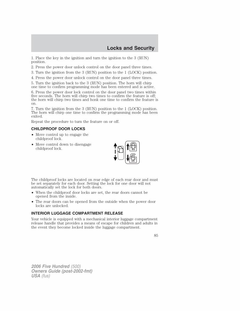
1. Place the key in the ignition and turn the ignition to the 3 (RUN)position.2. Press the power door unlock control on the door panel three times.3. Turn the ignition from the 3 (RUN) position to the 1 (LOCK) position.4. Press the power door unlock control on the door panel three times.5. Turn the ignition back to the 3 (RUN) position. The horn will chirpone time to confirm programming mode has been entered and is active.6. Press the power door lock control on the door panel two times withinfive seconds. The horn will chirp two times to confirm the feature is off;the horn will chirp two times and honk one time to confirm the feature ison.7. Turn the ignition from the 3 (RUN) position to the 1 (LOCK) position.The horn will chirp one time to confirm the programming mode has beenexited.Repeat the procedure to turn the feature on or off.
CHILDPROOF DOOR LOCKS• Move control up to engage the
childproof lock.
• Move control down to disengagechildproof lock.
The childproof locks are located on rear edge of each rear door and mustbe set separately for each door. Setting the lock for one door will notautomatically set the lock for both doors.• When the childproof door locks are set, the rear doors cannot be
opened from the inside.• The rear doors can be opened from the outside when the power door
locks are unlocked.
INTERIOR LUGGAGE COMPARTMENT RELEASEYour vehicle is equipped with a mechanical interior luggage compartmentrelease handle that provides a means of escape for children and adults inthe event they become locked inside the luggage compartment.
2006 Five Hundred (500)Owners Guide (post-2002-fmt)USA (fus)
Locks and Security
85
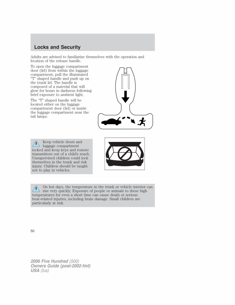
Adults are advised to familiarize themselves with the operation andlocation of the release handle.
To open the luggage compartmentdoor (lid) from within the luggagecompartment, pull the illuminated“T” shaped handle and push up onthe trunk lid. The handle iscomposed of a material that willglow for hours in darkness followingbrief exposure to ambient light.
The “T” shaped handle will belocated either on the luggagecompartment door (lid) or insidethe luggage compartment near thetail lamps.
Keep vehicle doors andluggage compartment
locked and keep keys and remotetransmitters out of a child’s reach.Unsupervised children could lockthemselves in the trunk and riskinjury. Children should be taughtnot to play in vehicles.
On hot days, the temperature in the trunk or vehicle interior canrise very quickly. Exposure of people or animals to these high
temperatures for even a short time can cause death or seriousheat-related injuries, including brain damage. Small children areparticularly at risk.
2006 Five Hundred (500)Owners Guide (post-2002-fmt)USA (fus)
Locks and Security
86
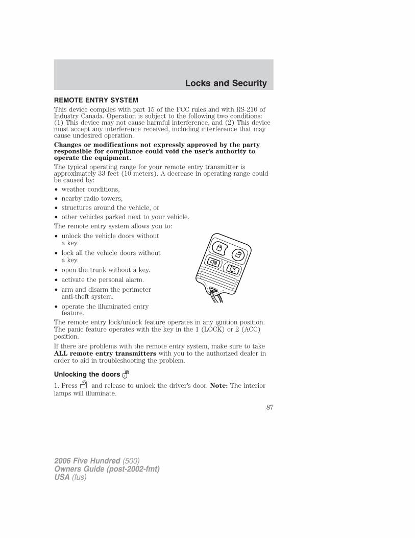
REMOTE ENTRY SYSTEMThis device complies with part 15 of the FCC rules and with RS-210 ofIndustry Canada. Operation is subject to the following two conditions:(1) This device may not cause harmful interference, and (2) This devicemust accept any interference received, including interference that maycause undesired operation.Changes or modifications not expressly approved by the partyresponsible for compliance could void the user’s authority tooperate the equipment.
The typical operating range for your remote entry transmitter isapproximately 33 feet (10 meters). A decrease in operating range couldbe caused by:• weather conditions,• nearby radio towers,• structures around the vehicle, or• other vehicles parked next to your vehicle.The remote entry system allows you to:
• unlock the vehicle doors withouta key.
• lock all the vehicle doors withouta key.
• open the trunk without a key.
• activate the personal alarm.
• arm and disarm the perimeteranti-theft system.
• operate the illuminated entryfeature.
The remote entry lock/unlock feature operates in any ignition position.The panic feature operates with the key in the 1 (LOCK) or 2 (ACC)position.
If there are problems with the remote entry system, make sure to takeALL remote entry transmitters with you to the authorized dealer inorder to aid in troubleshooting the problem.
Unlocking the doors
1. Press and release to unlock the driver’s door. Note: The interiorlamps will illuminate.
2006 Five Hundred (500)Owners Guide (post-2002-fmt)USA (fus)
Locks and Security
87
2. Press and release again within three seconds to unlock all thedoors.The remote entry system activates the illuminated entry feature; thisfeature turns on the lamps for 25 seconds or until the ignition is turnedto the 3 (RUN) position.The inside lights will not turn off if:• they have been turned on using the dimmer control or• any door is open.The battery saver feature will turn off the interior lamps 30 minutes afterthe ignition is turned to the 1 (LOCK) position.
Locking the doors
1. Press and release to lock all the doors. The turn lamps will flash.Note: If any door is not closed properly, the lamps will not flash.
2. Press and release again within three seconds to confirm that allthe doors are closed. Note: The doors will lock again, the horn will chirpand the turn lamps will flash once if all the doors and trunk are closed. Ifany door or the trunk is not closed, or if the hood is not closed invehicles equipped with the perimeter alarm feature, the horn will chirptwice and the lamps will not flash
Sounding a panic alarm
Press to activate the alarm. The horn will sound and the turn lampswill flash for a maximum of 3 minutes. Press again or turn the ignition tothe 3 (RUN) position to deactivate, or wait for the alarm to timeout in 3minutes.
Note: The panic alarm will only operate when the ignition is in the 1(LOCK) or 2 (ACC) position.
Opening the trunk
Press once to open the trunk.
• Ensure that the trunk is closed and latched before driving yourvehicle. Failure to properly latch the trunk may cause objects to fallout or block the driver’s rear view.
Memory seats/power mirrors/adjustable pedals (if equipped)The remote entry system can also control the memory seat /powermirrors/adjustable pedals feature.
2006 Five Hundred (500)Owners Guide (post-2002-fmt)USA (fus)
Locks and Security
88
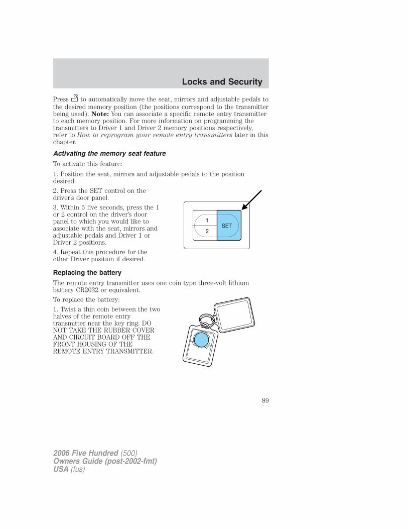
Press to automatically move the seat, mirrors and adjustable pedals tothe desired memory position (the positions correspond to the transmitterbeing used). Note: You can associate a specific remote entry transmitterto each memory position. For more information on programming thetransmitters to Driver 1 and Driver 2 memory positions respectively,refer to How to reprogram your remote entry transmitters later in thischapter.
Activating the memory seat feature
To activate this feature:
1. Position the seat, mirrors and adjustable pedals to the positiondesired.
2. Press the SET control on thedriver’s door panel.
3. Within 5 five seconds, press the 1or 2 control on the driver’s doorpanel to which you would like toassociate with the seat, mirrors andadjustable pedals and Driver 1 orDriver 2 positions.
4. Repeat this procedure for theother Driver position if desired.
Replacing the battery
The remote entry transmitter uses one coin type three-volt lithiumbattery CR2032 or equivalent.
To replace the battery:
1. Twist a thin coin between the twohalves of the remote entrytransmitter near the key ring. DONOT TAKE THE RUBBER COVERAND CIRCUIT BOARD OFF THEFRONT HOUSING OF THEREMOTE ENTRY TRANSMITTER.
2006 Five Hundred (500)Owners Guide (post-2002-fmt)USA (fus)
Locks and Security
89
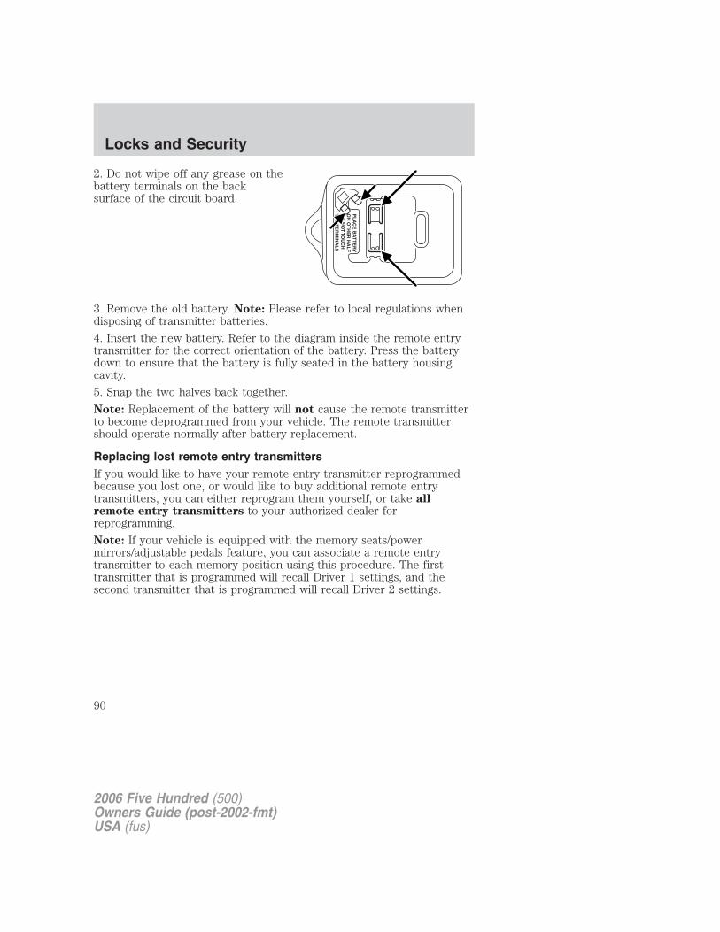
2. Do not wipe off any grease on thebattery terminals on the backsurface of the circuit board.
3. Remove the old battery. Note: Please refer to local regulations whendisposing of transmitter batteries.
4. Insert the new battery. Refer to the diagram inside the remote entrytransmitter for the correct orientation of the battery. Press the batterydown to ensure that the battery is fully seated in the battery housingcavity.
5. Snap the two halves back together.
Note: Replacement of the battery will not cause the remote transmitterto become deprogrammed from your vehicle. The remote transmittershould operate normally after battery replacement.
Replacing lost remote entry transmittersIf you would like to have your remote entry transmitter reprogrammedbecause you lost one, or would like to buy additional remote entrytransmitters, you can either reprogram them yourself, or take allremote entry transmitters to your authorized dealer forreprogramming.
Note: If your vehicle is equipped with the memory seats/powermirrors/adjustable pedals feature, you can associate a remote entrytransmitter to each memory position using this procedure. The firsttransmitter that is programmed will recall Driver 1 settings, and thesecond transmitter that is programmed will recall Driver 2 settings.
2006 Five Hundred (500)Owners Guide (post-2002-fmt)USA (fus)
Locks and Security
90
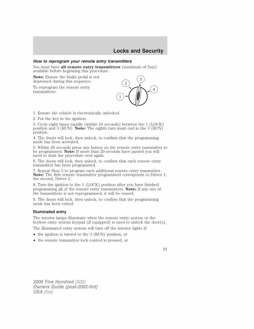
How to reprogram your remote entry transmittersYou must have all remote entry transmitters (maximum of four)available before beginning this procedure.
Note: Ensure the brake pedal is notdepressed during this sequence.
To reprogram the remote entrytransmitters:
1. Ensure the vehicle is electronically unlocked.2. Put the key in the ignition.3. Cycle eight times rapidly (within 10 seconds) between the 1 (LOCK)position and 3 (RUN). Note: The eighth turn must end in the 3 (RUN)position.4. The doors will lock, then unlock, to confirm that the programmingmode has been activated.5. Within 20 seconds press any button on the remote entry transmitter tobe programmed. Note: If more than 20 seconds have passed you willneed to start the procedure over again.6. The doors will lock, then unlock, to confirm that each remote entrytransmitter has been programmed.7. Repeat Step 5 to program each additional remote entry transmitter.Note: The first remote transmitter programmed corresponds to Driver 1;the second, Driver 2.
8. Turn the ignition to the 1 (LOCK) position after you have finishedprogramming all of the remote entry transmitters. Note: If any one ofthe transmitters is not reprogrammed, it will be erased.
9. The doors will lock, then unlock, to confirm that the programmingmode has been exited.
Illuminated entryThe interior lamps illuminate when the remote entry system or thekeyless entry system keypad (if equipped) is used to unlock the door(s).
The illuminated entry system will turn off the interior lights if:
• the ignition is turned to the 3 (RUN) position, or
• the remote transmitter lock control is pressed, or
2006 Five Hundred (500)Owners Guide (post-2002-fmt)USA (fus)
Locks and Security
91
• after 25 seconds of illumination.
The inside lights will not turn off if:
• they have been turned on with the dimmer control, or
• any door is open.
Battery saver
The battery saver will shut off the interior lamps 30 minutes after theignition has been turned to the 1 (LOCK) position.
• If the dome lamps were turned on using the panel dimmer control, thebattery saver will shut off them off 30 minutes after the ignition hasbeen turned to the 1 (LOCK) position.
• If the courtesy lamps were turned on because one of the vehicle doorswas opened, the battery saver will shut them off 10 minutes after theignition has been turned to the 1 (LOCK) position.
• The battery saver will shut off the headlamps and foglamps 10minutes after the ignition has been turned to the 1 (LOCK) position.
Illuminated exit
• When all vehicle doors and the trunk are closed, and the key isremoved from the ignition, the interior dome lamps (and the exteriormirror puddle lamps, if equipped) will illuminate.
The lights will turn off if all the doors and the trunk remain closed and
• 25 seconds elapse, or
• the key is inserted in the ignition.
2006 Five Hundred (500)Owners Guide (post-2002-fmt)USA (fus)
Locks and Security
92
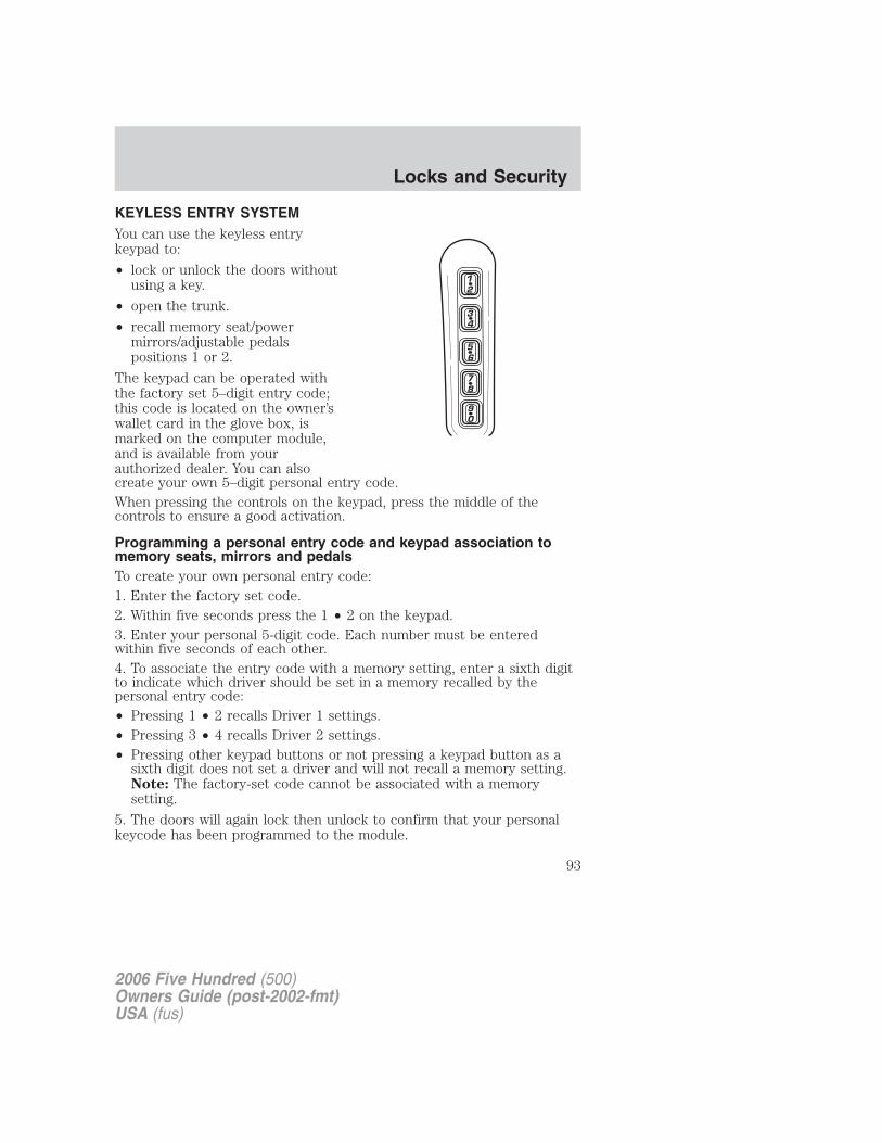
KEYLESS ENTRY SYSTEMYou can use the keyless entrykeypad to:
• lock or unlock the doors withoutusing a key.
• open the trunk.
• recall memory seat/powermirrors/adjustable pedalspositions 1 or 2.
The keypad can be operated withthe factory set 5–digit entry code;this code is located on the owner’swallet card in the glove box, ismarked on the computer module,and is available from yourauthorized dealer. You can alsocreate your own 5–digit personal entry code.When pressing the controls on the keypad, press the middle of thecontrols to ensure a good activation.
Programming a personal entry code and keypad association tomemory seats, mirrors and pedalsTo create your own personal entry code:1. Enter the factory set code.2. Within five seconds press the 1 • 2 on the keypad.3. Enter your personal 5-digit code. Each number must be enteredwithin five seconds of each other.4. To associate the entry code with a memory setting, enter a sixth digitto indicate which driver should be set in a memory recalled by thepersonal entry code:• Pressing 1 • 2 recalls Driver 1 settings.• Pressing 3 • 4 recalls Driver 2 settings.• Pressing other keypad buttons or not pressing a keypad button as a
sixth digit does not set a driver and will not recall a memory setting.Note: The factory-set code cannot be associated with a memorysetting.
5. The doors will again lock then unlock to confirm that your personalkeycode has been programmed to the module.
2006 Five Hundred (500)Owners Guide (post-2002-fmt)USA (fus)
Locks and Security
93
Tips:
• Do not set a code that uses five of the same number.• Do not use five numbers in sequential order.• The factory set code will work even if you have set your own personal
code.
Erasing personal code1. Enter the factory set 5–digit code.2. Within five seconds, press the 1 • 2 on the keypad and release.3. Press and hold the 1 • 2 for two seconds. This must be done withinfive seconds of completing Step 2.Your personal code is now erased and only the factory set 5–digit codewill work.
Anti-scan featureIf the wrong code has been entered 7 times (35 consecutive buttonpresses), the keypad will go into an anti-scan mode. This mode disablesthe keypad for one minute and the keypad lamp will flash.The anti-scan feature will turn off after:
• one minute of keypad inactivity.
• pressing the UNLOCK control on the remote entry transmitter.
• the ignition is turned to the 3 (RUN) position.
Unlocking and locking the doors using keyless entryTo unlock the driver’s door, enter the factory set 5-digit code or yourpersonal code. Each number must be pressed within five seconds of eachother. The interior lamps will illuminate.
To unlock all doors, enter the factory set code or your personal code,then press the 3 • 4 control within five seconds.
To open the trunk, enter the factory set code or your personal code,then press the 5 • 6 control within five seconds.
To lock all doors, press the 7 • 8 and the 9 • 0 at the same time. Youdo not need to enter the keypad code first.
AutolockThe autolock feature will lock all the doors when:
• all the doors are closed,
2006 Five Hundred (500)Owners Guide (post-2002-fmt)USA (fus)
Locks and Security
94
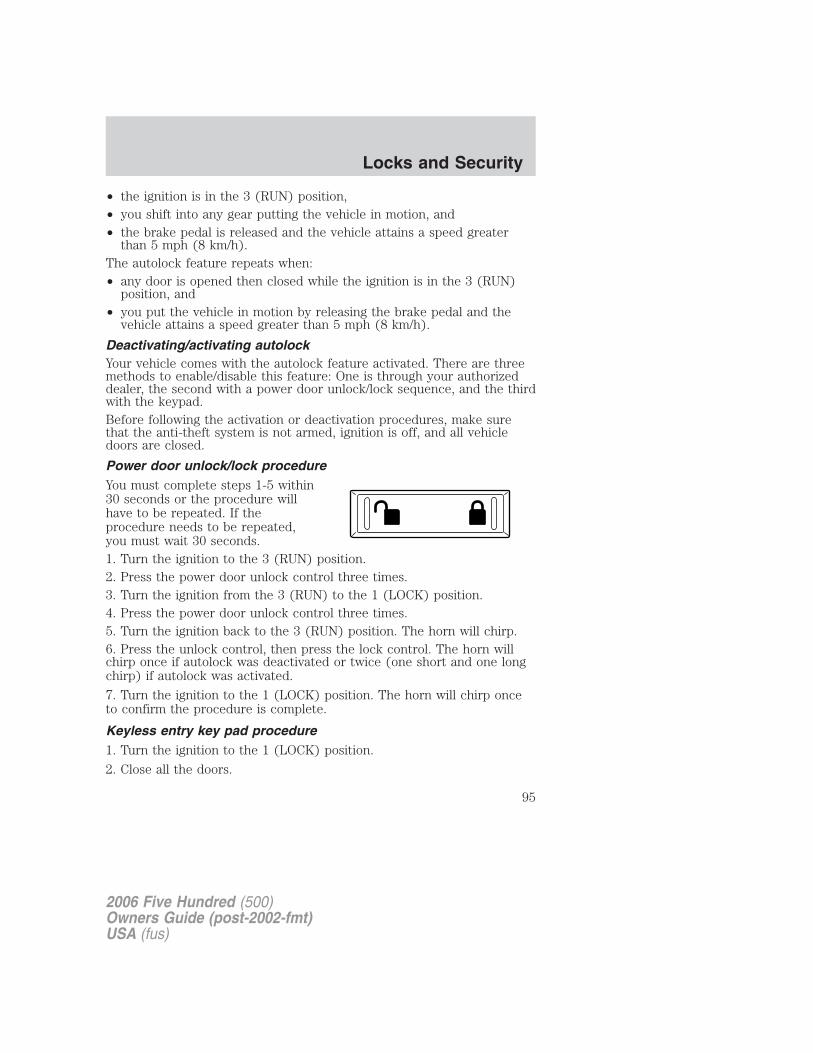
• the ignition is in the 3 (RUN) position,• you shift into any gear putting the vehicle in motion, and• the brake pedal is released and the vehicle attains a speed greater
than 5 mph (8 km/h).The autolock feature repeats when:• any door is opened then closed while the ignition is in the 3 (RUN)
position, and• you put the vehicle in motion by releasing the brake pedal and the
vehicle attains a speed greater than 5 mph (8 km/h).
Deactivating/activating autolockYour vehicle comes with the autolock feature activated. There are threemethods to enable/disable this feature: One is through your authorizeddealer, the second with a power door unlock/lock sequence, and the thirdwith the keypad.Before following the activation or deactivation procedures, make surethat the anti-theft system is not armed, ignition is off, and all vehicledoors are closed.
Power door unlock/lock procedureYou must complete steps 1-5 within30 seconds or the procedure willhave to be repeated. If theprocedure needs to be repeated,you must wait 30 seconds.1. Turn the ignition to the 3 (RUN) position.2. Press the power door unlock control three times.3. Turn the ignition from the 3 (RUN) to the 1 (LOCK) position.4. Press the power door unlock control three times.5. Turn the ignition back to the 3 (RUN) position. The horn will chirp.6. Press the unlock control, then press the lock control. The horn willchirp once if autolock was deactivated or twice (one short and one longchirp) if autolock was activated.
7. Turn the ignition to the 1 (LOCK) position. The horn will chirp onceto confirm the procedure is complete.
Keyless entry key pad procedure1. Turn the ignition to the 1 (LOCK) position.
2. Close all the doors.
2006 Five Hundred (500)Owners Guide (post-2002-fmt)USA (fus)
Locks and Security
95
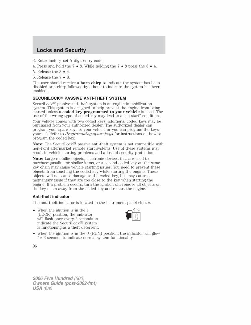
3. Enter factory–set 5–digit entry code.4. Press and hold the 7 • 8. While holding the 7 • 8 press the 3 • 4.5. Release the 3 • 4.6. Release the 7 • 8.The user should receive a horn chirp to indicate the system has beendisabled or a chirp followed by a honk to indicate the system has beenenabled.
SECURILOCK� PASSIVE ANTI-THEFT SYSTEMSecuriLock� passive anti-theft system is an engine immobilizationsystem. This system is designed to help prevent the engine from beingstarted unless a coded key programmed to your vehicle is used. Theuse of the wrong type of coded key may lead to a “no-start” condition.Your vehicle comes with two coded keys; additional coded keys may bepurchased from your authorized dealer. The authorized dealer canprogram your spare keys to your vehicle or you can program the keysyourself. Refer to Programming spare keys for instructions on how toprogram the coded key.
Note: The SecuriLock� passive anti-theft system is not compatible withnon-Ford aftermarket remote start systems. Use of these systems mayresult in vehicle starting problems and a loss of security protection.
Note: Large metallic objects, electronic devices that are used topurchase gasoline or similar items, or a second coded key on the samekey chain may cause vehicle starting issues. You need to prevent theseobjects from touching the coded key while starting the engine. Theseobjects will not cause damage to the coded key, but may cause amomentary issue if they are too close to the key when starting theengine. If a problem occurs, turn the ignition off, remove all objects onthe key chain away from the coded key and restart the engine.
Anti-theft indicatorThe anti-theft indicator is located in the instrument panel cluster.
• When the ignition is in the 1(LOCK) position, the indicatorwill flash once every 2 seconds toindicate the SecuriLock� systemis functioning as a theft deterrent.
• When the ignition is in the 3 (RUN) position, the indicator will glowfor 3 seconds to indicate normal system functionality.
2006 Five Hundred (500)Owners Guide (post-2002-fmt)USA (fus)
Locks and Security
96
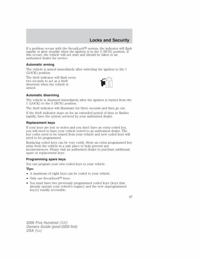
If a problem occurs with the SecuriLock� system, the indicator will flashrapidly or glow steadily when the ignition is in the 3 (RUN) position. Ifthis occurs, the vehicle will not start and should be taken to anauthorized dealer for service.
Automatic armingThe vehicle is armed immediately after switching the ignition to the 1(LOCK) position.
The theft indicator will flash everytwo seconds to act as a theftdeterrent when the vehicle isarmed.
Automatic disarmingThe vehicle is disarmed immediately after the ignition is turned from the1 (LOCK) to the 3 (RUN) position.
The theft indicator will illuminate for three seconds and then go out.
If the theft indicator stays on for an extended period of time or flashesrapidly, have the system serviced by your authorized dealer.
Replacement keysIf your keys are lost or stolen and you don’t have an extra coded key,you will need to have your vehicle towed to an authorized dealer. Thekey codes need to be erased from your vehicle and new coded keys willneed to be programmed.
Replacing coded keys can be very costly. Store an extra programmed keyaway from the vehicle in a safe place to help prevent anyinconveniences. Please visit an authorized dealer to purchase additionalspare or replacement keys.
Programming spare keysYou can program your own coded keys to your vehicle.
Tips:
• A maximum of eight keys can be coded to your vehicle.
• Only use SecuriLock� keys.
• You must have two previously programmed coded keys (keys thatalready operate your vehicle’s engine) and the new unprogrammedkey(s) readily accessible.
2006 Five Hundred (500)Owners Guide (post-2002-fmt)USA (fus)
Locks and Security
97
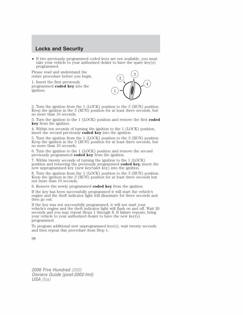
• If two previously programmed coded keys are not available, you musttake your vehicle to your authorized dealer to have the spare key(s)programmed.
Please read and understand theentire procedure before you begin.
1. Insert the first previouslyprogrammed coded key into theignition.
2. Turn the ignition from the 1 (LOCK) position to the 3 (RUN) position.Keep the ignition in the 3 (RUN) position for at least three seconds, butno more than 10 seconds.3. Turn the ignition to the 1 (LOCK) position and remove the first codedkey from the ignition.4. Within ten seconds of turning the ignition to the 1 (LOCK) position,insert the second previously coded key into the ignition.5. Turn the ignition from the 1 (LOCK) position to the 3 (RUN) position.Keep the ignition in the 3 (RUN) position for at least three seconds, butno more than 10 seconds.6. Turn the ignition to the 1 (LOCK) position and remove the secondpreviously programmed coded key from the ignition.7. Within twenty seconds of turning the ignition to the 1 (LOCK)position and removing the previously programmed coded key, insert thenew unprogrammed key (new key/valet key) into the ignition.8. Turn the ignition from the 1 (LOCK) position to the 3 (RUN) position.Keep the ignition in the 3 (RUN) position for at least three seconds butnot more than 10 seconds.9. Remove the newly programmed coded key from the ignition.If the key has been successfully programmed it will start the vehicle’sengine and the theft indicator light will illuminate for three seconds andthen go out.If the key was not successfully programmed, it will not start yourvehicle’s engine and the theft indicator light will flash on and off. Wait 20seconds and you may repeat Steps 1 through 8. If failure repeats, bringyour vehicle to your authorized dealer to have the new key(s)programmed.
To program additional new unprogrammed key(s), wait twenty secondsand then repeat this procedure from Step 1.
2006 Five Hundred (500)Owners Guide (post-2002-fmt)USA (fus)
Locks and Security
98
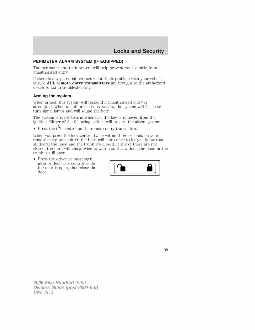
PERIMETER ALARM SYSTEM (IF EQUIPPED)
The perimeter anti-theft system will help prevent your vehicle fromunauthorized entry.
If there is any potential perimeter anti-theft problem with your vehicle,ensure ALL remote entry transmitters are brought to the authorizeddealer to aid in troubleshooting.
Arming the system
When armed, this system will respond if unauthorized entry isattempted. When unauthorized entry occurs, the system will flash theturn signal lamps and will sound the horn.
The system is ready to arm whenever the key is removed from theignition. Either of the following actions will prearm the alarm system:
• Press the control on the remote entry transmitter.
When you press the lock control twice within three seconds on yourremote entry transmitter, the horn will chirp once to let you know thatall doors, the hood and the trunk are closed. If any of these are notclosed, the horn will chirp twice to warn you that a door, the hood or thetrunk is still open.
• Press the driver or passengerinterior door lock control whilethe door is open, then close thedoor.
2006 Five Hundred (500)Owners Guide (post-2002-fmt)USA (fus)
Locks and Security
99
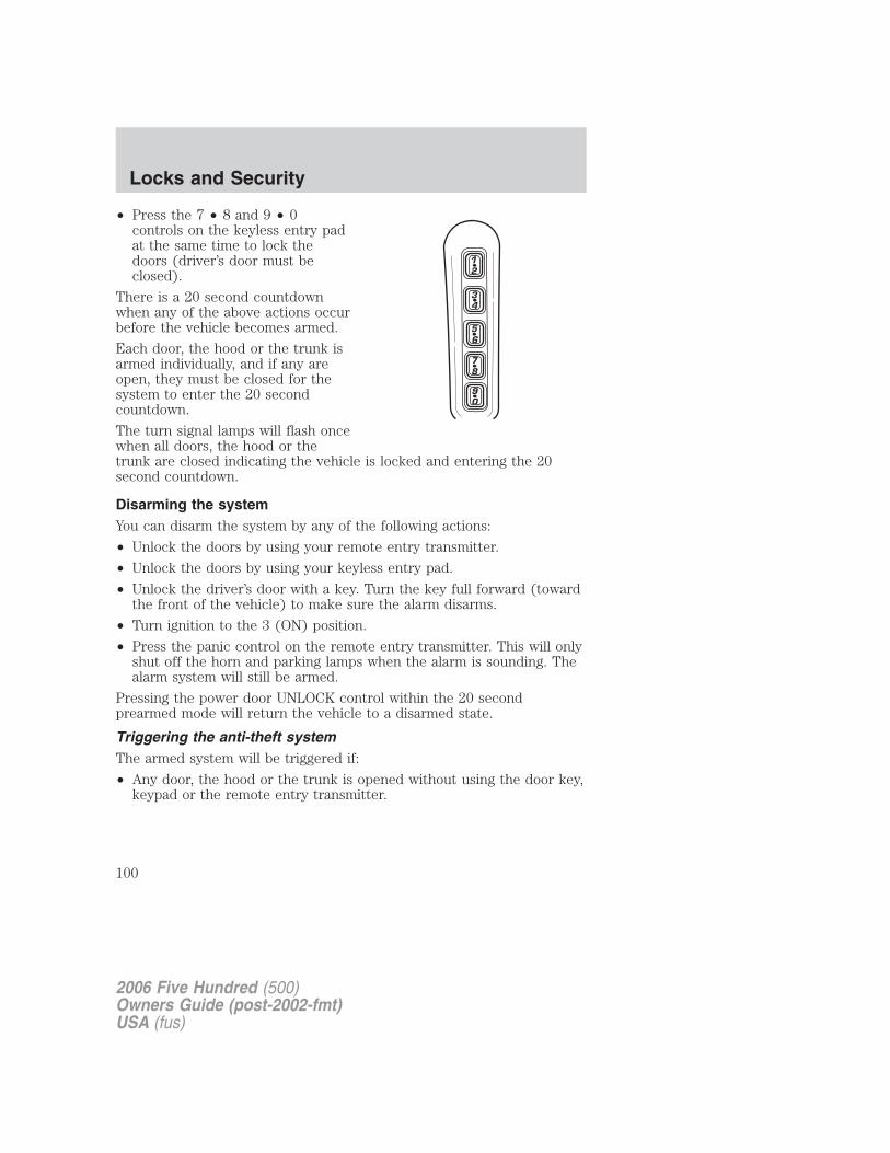
• Press the 7 • 8 and 9 • 0controls on the keyless entry padat the same time to lock thedoors (driver’s door must beclosed).
There is a 20 second countdownwhen any of the above actions occurbefore the vehicle becomes armed.
Each door, the hood or the trunk isarmed individually, and if any areopen, they must be closed for thesystem to enter the 20 secondcountdown.
The turn signal lamps will flash oncewhen all doors, the hood or thetrunk are closed indicating the vehicle is locked and entering the 20second countdown.
Disarming the systemYou can disarm the system by any of the following actions:
• Unlock the doors by using your remote entry transmitter.
• Unlock the doors by using your keyless entry pad.
• Unlock the driver’s door with a key. Turn the key full forward (towardthe front of the vehicle) to make sure the alarm disarms.
• Turn ignition to the 3 (ON) position.
• Press the panic control on the remote entry transmitter. This will onlyshut off the horn and parking lamps when the alarm is sounding. Thealarm system will still be armed.
Pressing the power door UNLOCK control within the 20 secondprearmed mode will return the vehicle to a disarmed state.
Triggering the anti-theft systemThe armed system will be triggered if:
• Any door, the hood or the trunk is opened without using the door key,keypad or the remote entry transmitter.
2006 Five Hundred (500)Owners Guide (post-2002-fmt)USA (fus)
Locks and Security
100
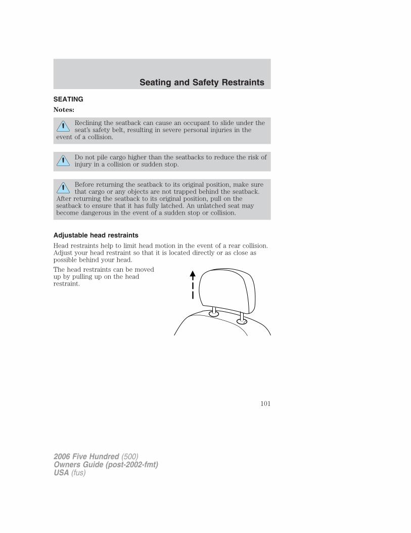
SEATING
Notes:
Reclining the seatback can cause an occupant to slide under theseat’s safety belt, resulting in severe personal injuries in the
event of a collision.
Do not pile cargo higher than the seatbacks to reduce the risk ofinjury in a collision or sudden stop.
Before returning the seatback to its original position, make surethat cargo or any objects are not trapped behind the seatback.
After returning the seatback to its original position, pull on theseatback to ensure that it has fully latched. An unlatched seat maybecome dangerous in the event of a sudden stop or collision.
Adjustable head restraints
Head restraints help to limit head motion in the event of a rear collision.Adjust your head restraint so that it is located directly or as close aspossible behind your head.
The head restraints can be movedup by pulling up on the headrestraint.
2006 Five Hundred (500)Owners Guide (post-2002-fmt)USA (fus)
Seating and Safety Restraints
101
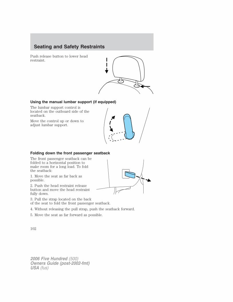
Push release button to lower headrestraint.
Using the manual lumbar support (if equipped)The lumbar support control islocated on the outboard side of theseatback.
Move the control up or down toadjust lumbar support.
Folding down the front passenger seatbackThe front passenger seatback can befolded to a horizontal position tomake room for a long load. To foldthe seatback:
1. Move the seat as far back aspossible.
2. Push the head restraint releasebutton and move the head restraintfully down.
3. Pull the strap located on the backof the seat to fold the front passenger seatback.
4. Without releasing the pull strap, push the seatback forward.
5. Move the seat as far forward as possible.
2006 Five Hundred (500)Owners Guide (post-2002-fmt)USA (fus)
Seating and Safety Restraints
102
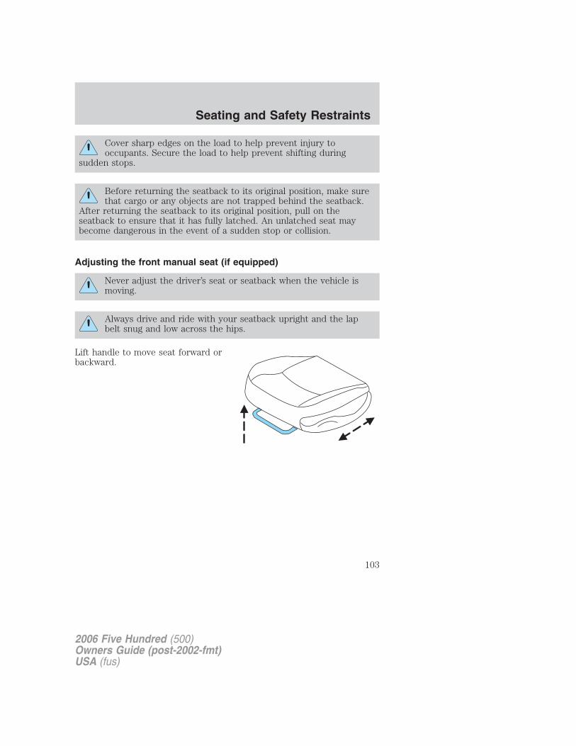
Cover sharp edges on the load to help prevent injury tooccupants. Secure the load to help prevent shifting during
sudden stops.
Before returning the seatback to its original position, make surethat cargo or any objects are not trapped behind the seatback.
After returning the seatback to its original position, pull on theseatback to ensure that it has fully latched. An unlatched seat maybecome dangerous in the event of a sudden stop or collision.
Adjusting the front manual seat (if equipped)
Never adjust the driver’s seat or seatback when the vehicle ismoving.
Always drive and ride with your seatback upright and the lapbelt snug and low across the hips.
Lift handle to move seat forward orbackward.
2006 Five Hundred (500)Owners Guide (post-2002-fmt)USA (fus)
Seating and Safety Restraints
103
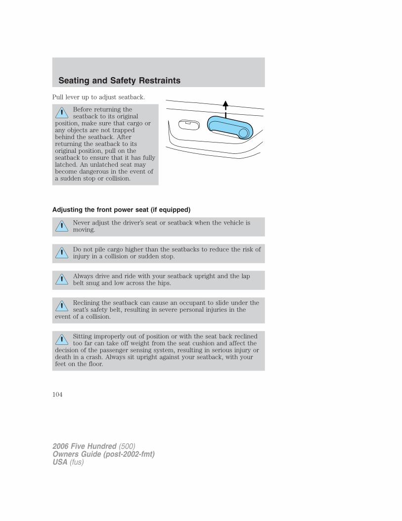
Pull lever up to adjust seatback.
Before returning theseatback to its original
position, make sure that cargo orany objects are not trappedbehind the seatback. Afterreturning the seatback to itsoriginal position, pull on theseatback to ensure that it has fullylatched. An unlatched seat maybecome dangerous in the event ofa sudden stop or collision.
Adjusting the front power seat (if equipped)
Never adjust the driver’s seat or seatback when the vehicle ismoving.
Do not pile cargo higher than the seatbacks to reduce the risk ofinjury in a collision or sudden stop.
Always drive and ride with your seatback upright and the lapbelt snug and low across the hips.
Reclining the seatback can cause an occupant to slide under theseat’s safety belt, resulting in severe personal injuries in the
event of a collision.
Sitting improperly out of position or with the seat back reclinedtoo far can take off weight from the seat cushion and affect the
decision of the passenger sensing system, resulting in serious injury ordeath in a crash. Always sit upright against your seatback, with yourfeet on the floor.
2006 Five Hundred (500)Owners Guide (post-2002-fmt)USA (fus)
Seating and Safety Restraints
104
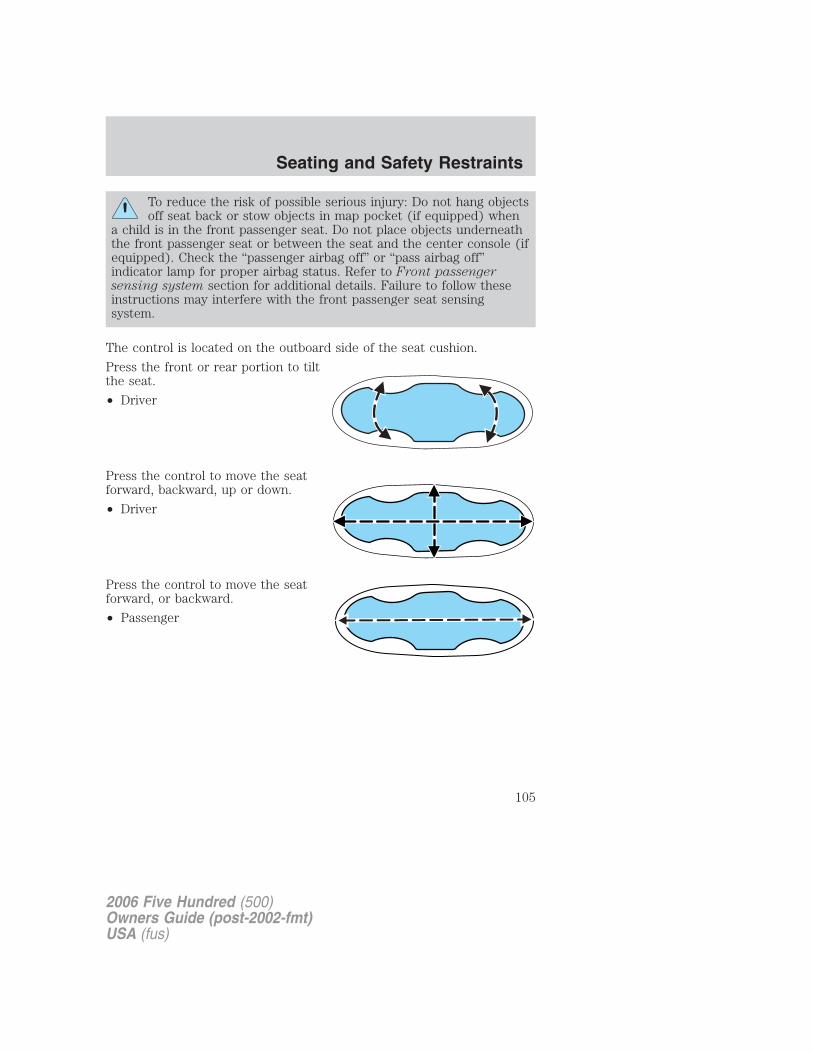
To reduce the risk of possible serious injury: Do not hang objectsoff seat back or stow objects in map pocket (if equipped) when
a child is in the front passenger seat. Do not place objects underneaththe front passenger seat or between the seat and the center console (ifequipped). Check the “passenger airbag off” or “pass airbag off”indicator lamp for proper airbag status. Refer to Front passengersensing system section for additional details. Failure to follow theseinstructions may interfere with the front passenger seat sensingsystem.
The control is located on the outboard side of the seat cushion.
Press the front or rear portion to tiltthe seat.
• Driver
Press the control to move the seatforward, backward, up or down.
• Driver
Press the control to move the seatforward, or backward.
• Passenger
2006 Five Hundred (500)Owners Guide (post-2002-fmt)USA (fus)
Seating and Safety Restraints
105
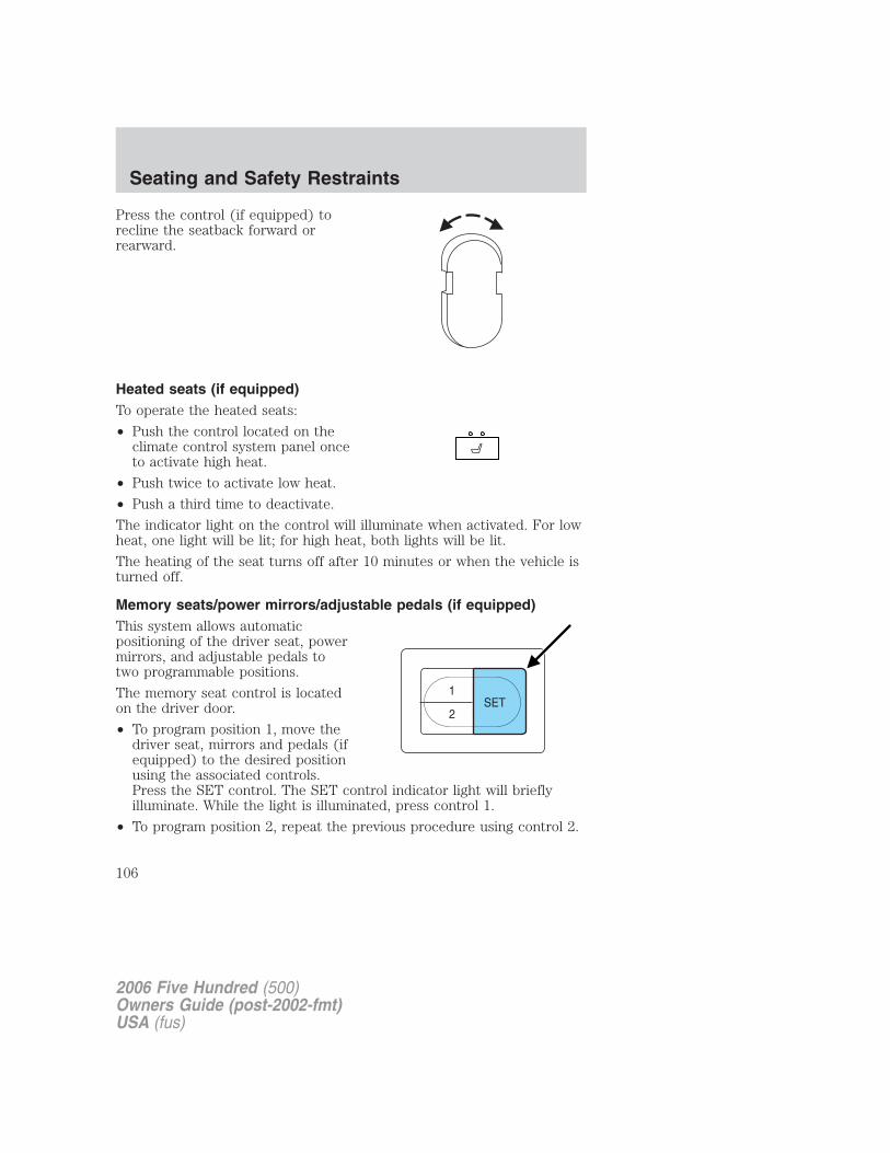
Press the control (if equipped) torecline the seatback forward orrearward.
Heated seats (if equipped)To operate the heated seats:
• Push the control located on theclimate control system panel onceto activate high heat.
• Push twice to activate low heat.
• Push a third time to deactivate.
The indicator light on the control will illuminate when activated. For lowheat, one light will be lit; for high heat, both lights will be lit.
The heating of the seat turns off after 10 minutes or when the vehicle isturned off.
Memory seats/power mirrors/adjustable pedals (if equipped)This system allows automaticpositioning of the driver seat, powermirrors, and adjustable pedals totwo programmable positions.
The memory seat control is locatedon the driver door.
• To program position 1, move thedriver seat, mirrors and pedals (ifequipped) to the desired positionusing the associated controls.Press the SET control. The SET control indicator light will brieflyilluminate. While the light is illuminated, press control 1.
• To program position 2, repeat the previous procedure using control 2.
2006 Five Hundred (500)Owners Guide (post-2002-fmt)USA (fus)
Seating and Safety Restraints
106
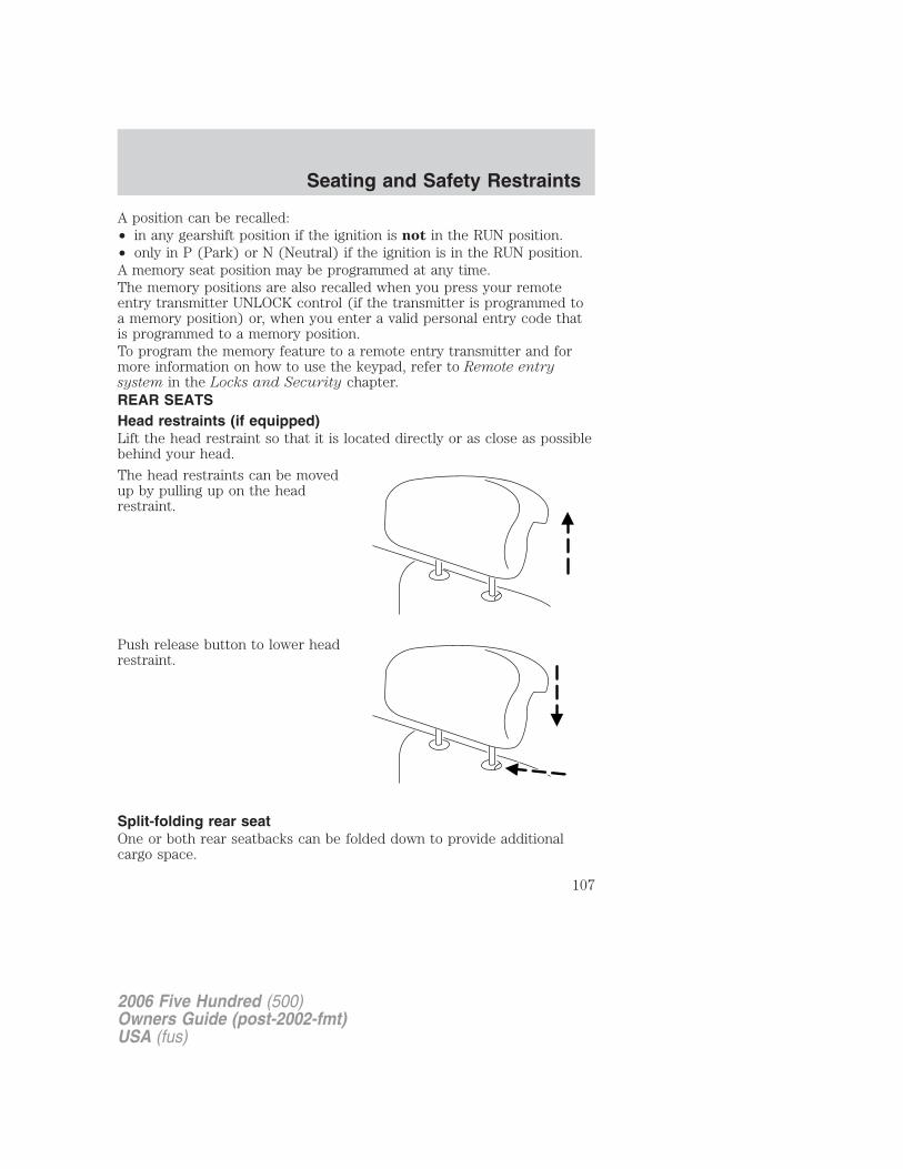
A position can be recalled:• in any gearshift position if the ignition is not in the RUN position.• only in P (Park) or N (Neutral) if the ignition is in the RUN position.A memory seat position may be programmed at any time.The memory positions are also recalled when you press your remoteentry transmitter UNLOCK control (if the transmitter is programmed toa memory position) or, when you enter a valid personal entry code thatis programmed to a memory position.To program the memory feature to a remote entry transmitter and formore information on how to use the keypad, refer to Remote entrysystem in the Locks and Security chapter.REAR SEATSHead restraints (if equipped)Lift the head restraint so that it is located directly or as close as possiblebehind your head.
The head restraints can be movedup by pulling up on the headrestraint.
Push release button to lower headrestraint.
Split-folding rear seatOne or both rear seatbacks can be folded down to provide additionalcargo space.
2006 Five Hundred (500)Owners Guide (post-2002-fmt)USA (fus)
Seating and Safety Restraints
107
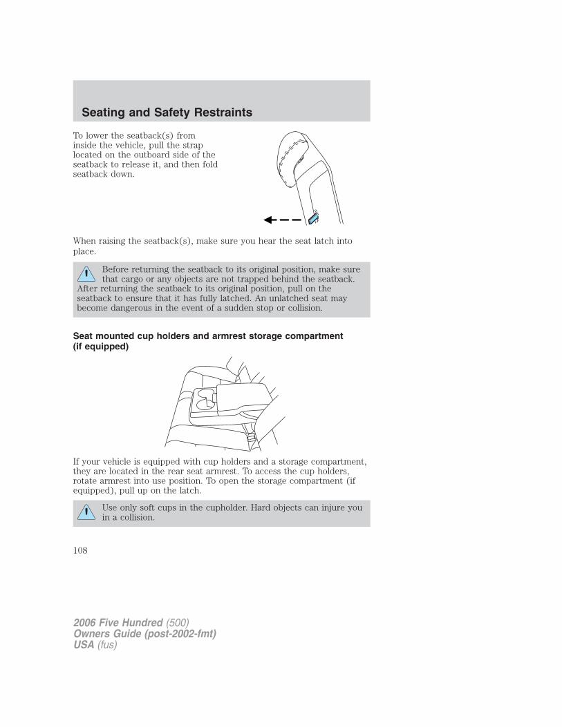
To lower the seatback(s) frominside the vehicle, pull the straplocated on the outboard side of theseatback to release it, and then foldseatback down.
When raising the seatback(s), make sure you hear the seat latch intoplace.
Before returning the seatback to its original position, make surethat cargo or any objects are not trapped behind the seatback.
After returning the seatback to its original position, pull on theseatback to ensure that it has fully latched. An unlatched seat maybecome dangerous in the event of a sudden stop or collision.
Seat mounted cup holders and armrest storage compartment(if equipped)
If your vehicle is equipped with cup holders and a storage compartment,they are located in the rear seat armrest. To access the cup holders,rotate armrest into use position. To open the storage compartment (ifequipped), pull up on the latch.
Use only soft cups in the cupholder. Hard objects can injure youin a collision.
2006 Five Hundred (500)Owners Guide (post-2002-fmt)USA (fus)
Seating and Safety Restraints
108
SAFETY RESTRAINTS
Personal Safety System�
The Personal Safety System� provides an improved overall level offrontal crash protection to front seat occupants and is designed to helpfurther reduce the risk of airbag-related injuries. The system is able toanalyze different occupant conditions and crash severity before activatingthe appropriate safety devices to help better protect a range ofoccupants in a variety of frontal crash situations.Your vehicle’s Personal Safety System� consists of:• Driver and passenger dual-stage airbag supplemental restraints.• Front outboard safety belts with pretensioners, energy management
retractors (first row only), and safety belt usage sensors.• Driver’s seat position sensor.• Passenger occupant classification sensor• Front crash severity sensor.• Restraints Control Module (RCM) with impact and safing sensors.• Restraint system warning light and back-up tone.• The electrical wiring for the airbags, crash sensor(s), safety belt
pretensioners, front safety belt usage sensors, driver seat positionsensor, passenger occupant classification sensor, and indicator lights.
How does the Personal Safety System� work?The Personal Safety System� can adapt the deployment strategy of yourvehicle’s safety devices according to crash severity and occupantconditions. A collection of crash and occupant sensors providesinformation to the Restraints Control Module (RCM). During a crash, theRCM activates the safety belt pretensioners and/or either one or bothstages of the dual-stage airbag supplemental restraints based on crashseverity and occupant conditions.
The fact that the pretensioners or airbags did not activate for both frontseat occupants in a collision does not mean that something is wrong withthe system. Rather, it means the Personal Safety System� determinedthe accident conditions (crash severity, belt usage, etc.) were notappropriate to activate these safety devices. Front airbags are designedto activate only in frontal and near-frontal collisions (not rollovers, sideimpacts or rear impacts) unless the collision causes sufficientlongitudinal deceleration. The pretensioners are designed to activate infrontal and near-frontal collisions, and in side collisions and rolloverswhen the vehicle is equipped with the Safety Canopy� system.
2006 Five Hundred (500)Owners Guide (post-2002-fmt)USA (fus)
Seating and Safety Restraints
109
Driver and passenger dual-stage airbag supplemental restraintsThe dual-stage airbags offer the capability to tailor the level of airbaginflation energy. A lower, less forceful energy level is provided for morecommon, moderate-severity impacts. A higher energy level is used forthe most severe impacts. Refer to Airbag supplemental restraintssection in this chapter.
Front crash severity sensorThe front crash severity sensor enhances the ability to detect theseverity of an impact. Positioned up front, it provides valuableinformation early in the crash event on the severity of the impact. Thisallows your Personal Safety System� to distinguish between differentlevels of crash severity and modify the deployment strategy of thedual-stage airbags and safety belt pretensioners.
Driver’s seat position sensorThe driver’s seat position sensor allows your Personal Safety System� totailor the deployment level of the driver dual-stage airbag based on seatposition. The system is designed to help protect smaller drivers sittingclose to the driver airbag by providing a lower airbag output level.
Front passenger sensing systemFor airbags to do their job they must inflate with great force, and thisforce can pose a potentially deadly risk to occupants that are very closeto the airbag when it begins to inflate. For some occupants, this occursbecause they are initially sitting very close to the airbag. For otheroccupants, this occurs when the occupant is not properly restrained bysafety belts or child safety seats and they move forward during pre-crashbraking. The most effective way to reduce the risk of unnecessaryinjuries is to make sure all occupants are properly restrained. Accidentstatistics suggest that children are much safer when properly restrainedin the rear seating positions than in the front.
Air bags can kill or injure a child in a child seat. NEVER place arear-facing child seat in front of an active air bag. If you must
use a forward-facing child seat in the front seat, move the seat all theway back.
Always transport children 12 years old and under in the backseat and always properly use appropriate child restraints.
The front passenger sensing system can automatically turn off thepassenger front airbag. The system is designed to help protect small
2006 Five Hundred (500)Owners Guide (post-2002-fmt)USA (fus)
Seating and Safety Restraints
110
(child size) occupants from airbag deployments when they areimproperly seated or restrained in the front passenger seat contrary toproper child-seating or restraint usage recommendations. Even with thistechnology, parents are STRONGLY encouraged to always properlyrestrain children in the rear seat. The sensor also turns off the passengerfront airbag and seat-mounted side airbag (if equipped) when thepassenger seat is empty to prevent unnecessary replacement of airbag(s)after a collision.
Front safety belt usage sensorsThe front safety belt usage sensors detect whether or not the driver andfront outboard passenger safety belts are fastened. This informationallows your Personal Safety System� to tailor the airbag deployment andsafety belt pretensioner activation depending upon safety belt usage.Refer to Safety belt section in this chapter.
Front safety belt pretensionersThe safety belt pretensioners at the front outboard seating positions aredesigned to tighten the safety belts firmly against the occupant’s bodyduring frontal collisions, and in side collisions and rollovers when thevehicle is equipped with the Safety Canopy� system. This helps increasethe effectiveness of the safety belts. In frontal collisions, the safety beltpretensioners can be activated alone or, if the collision is of sufficientseverity, together with the front airbags.
Front safety belt energy management retractorsThe front outboard safety belt energy management retractors allowwebbing to be pulled out of the retractor in a gradual and controlledmanner in response to the occupant’s forward momentum. This helpsreduce the risk of force-related injuries to the occupant’s chest bylimiting the load on the occupant. Refer to Energy management featuresection in this chapter.
Determining if the Personal Safety System� is operationalThe Personal Safety System� uses a warning light in the instrumentcluster or a back-up tone to indicate the condition of the system. Referto the Warning lights and chimes section in the Instrument Clusterchapter. Routine maintenance of the Personal Safety System� is notrequired.
The Restraints Control Module (RCM) monitors its own internal circuitsand the circuits for the airbag supplemental restraints, crash sensor(s),safety belt pretensioners, front safety belt buckle sensors, driver seat
2006 Five Hundred (500)Owners Guide (post-2002-fmt)USA (fus)
Seating and Safety Restraints
111
position sensor, and passenger occupant classification sensor. In addition,the RCM also monitors the restraints warning light in the instrumentcluster. A difficulty with the system is indicated by one or more of thefollowing.
• The warning light will either flash or stay lit.
• The warning light will not illuminate immediately after ignition isturned on.
• A series of five beeps will be heard. The tone pattern will repeatperiodically until the problem and warning light are repaired.
If any of these things happen, even intermittently, have the PersonalSafety System� serviced at an authorized dealer immediately. Unlessserviced, the system may not function properly in the event of acollision.
Safety belt precautions
Always drive and ride with your seatback upright and the lapbelt snug and low across the hips.
To reduce the risk of injury, make sure children sit where theycan be properly restrained.
Never let a passenger hold a child on his or her lap while thevehicle is moving. The passenger cannot protect the child from
injury in a collision.
All occupants of the vehicle, including the driver, should alwaysproperly wear their safety belts, even when an air bag
supplemental restraint system (SRS) is provided.
It is extremely dangerous to ride in a cargo area, inside oroutside of a vehicle. In a collision, people riding in these areas
are more likely to be seriously injured or killed. Do not allow people toride in any area of your vehicle that is not equipped with seats andsafety belts. Be sure everyone in your vehicle is in a seat and using asafety belt properly.
2006 Five Hundred (500)Owners Guide (post-2002-fmt)USA (fus)
Seating and Safety Restraints
112
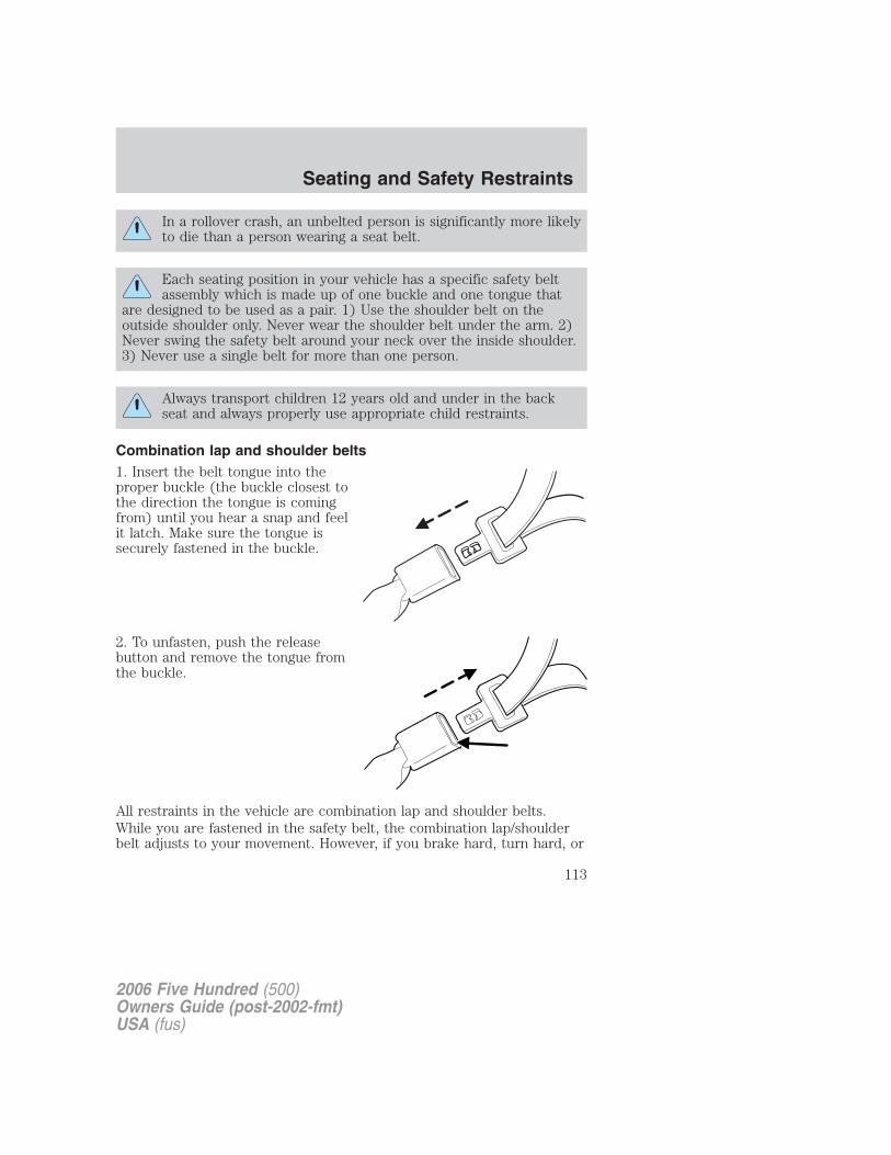
In a rollover crash, an unbelted person is significantly more likelyto die than a person wearing a seat belt.
Each seating position in your vehicle has a specific safety beltassembly which is made up of one buckle and one tongue that
are designed to be used as a pair. 1) Use the shoulder belt on theoutside shoulder only. Never wear the shoulder belt under the arm. 2)Never swing the safety belt around your neck over the inside shoulder.3) Never use a single belt for more than one person.
Always transport children 12 years old and under in the backseat and always properly use appropriate child restraints.
Combination lap and shoulder belts1. Insert the belt tongue into theproper buckle (the buckle closest tothe direction the tongue is comingfrom) until you hear a snap and feelit latch. Make sure the tongue issecurely fastened in the buckle.
2. To unfasten, push the releasebutton and remove the tongue fromthe buckle.
All restraints in the vehicle are combination lap and shoulder belts.While you are fastened in the safety belt, the combination lap/shoulderbelt adjusts to your movement. However, if you brake hard, turn hard, or
2006 Five Hundred (500)Owners Guide (post-2002-fmt)USA (fus)
Seating and Safety Restraints
113
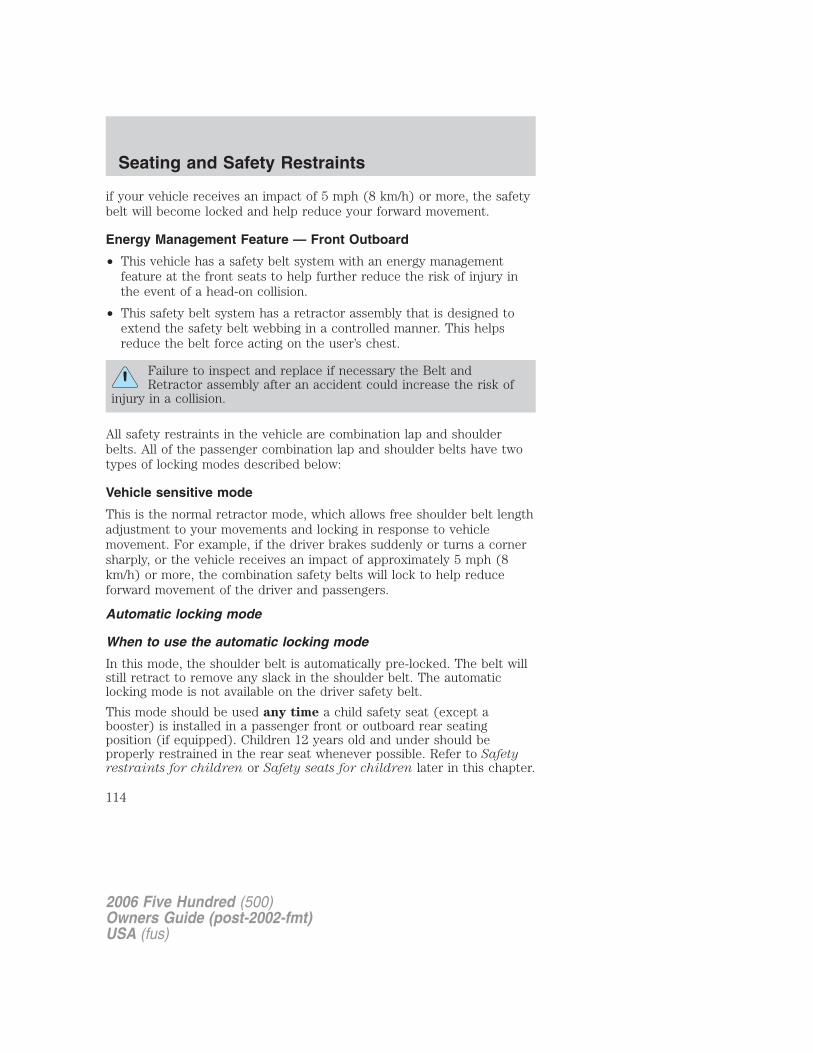
if your vehicle receives an impact of 5 mph (8 km/h) or more, the safetybelt will become locked and help reduce your forward movement.
Energy Management Feature — Front Outboard
• This vehicle has a safety belt system with an energy managementfeature at the front seats to help further reduce the risk of injury inthe event of a head-on collision.
• This safety belt system has a retractor assembly that is designed toextend the safety belt webbing in a controlled manner. This helpsreduce the belt force acting on the user’s chest.
Failure to inspect and replace if necessary the Belt andRetractor assembly after an accident could increase the risk of
injury in a collision.
All safety restraints in the vehicle are combination lap and shoulderbelts. All of the passenger combination lap and shoulder belts have twotypes of locking modes described below:
Vehicle sensitive mode
This is the normal retractor mode, which allows free shoulder belt lengthadjustment to your movements and locking in response to vehiclemovement. For example, if the driver brakes suddenly or turns a cornersharply, or the vehicle receives an impact of approximately 5 mph (8km/h) or more, the combination safety belts will lock to help reduceforward movement of the driver and passengers.
Automatic locking mode
When to use the automatic locking mode
In this mode, the shoulder belt is automatically pre-locked. The belt willstill retract to remove any slack in the shoulder belt. The automaticlocking mode is not available on the driver safety belt.
This mode should be used any time a child safety seat (except abooster) is installed in a passenger front or outboard rear seatingposition (if equipped). Children 12 years old and under should beproperly restrained in the rear seat whenever possible. Refer to Safetyrestraints for children or Safety seats for children later in this chapter.
2006 Five Hundred (500)Owners Guide (post-2002-fmt)USA (fus)
Seating and Safety Restraints
114
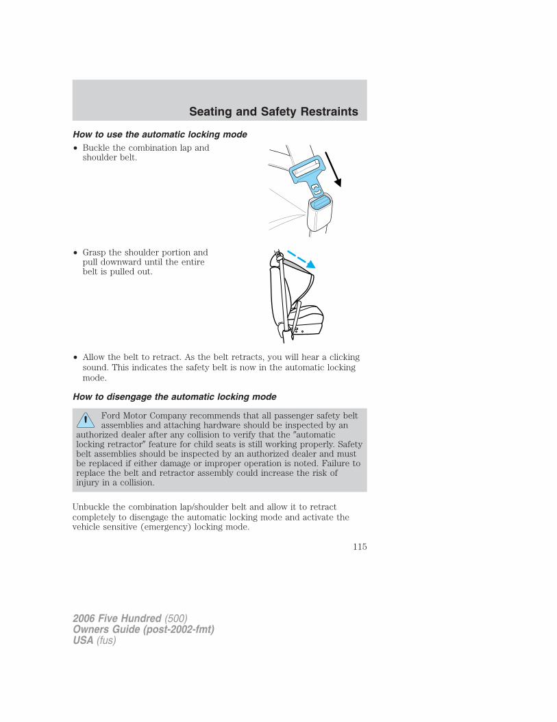
How to use the automatic locking mode• Buckle the combination lap and
shoulder belt.
• Grasp the shoulder portion andpull downward until the entirebelt is pulled out.
• Allow the belt to retract. As the belt retracts, you will hear a clickingsound. This indicates the safety belt is now in the automatic lockingmode.
How to disengage the automatic locking mode
Ford Motor Company recommends that all passenger safety beltassemblies and attaching hardware should be inspected by an
authorized dealer after any collision to verify that the �automaticlocking retractor� feature for child seats is still working properly. Safetybelt assemblies should be inspected by an authorized dealer and mustbe replaced if either damage or improper operation is noted. Failure toreplace the belt and retractor assembly could increase the risk ofinjury in a collision.
Unbuckle the combination lap/shoulder belt and allow it to retractcompletely to disengage the automatic locking mode and activate thevehicle sensitive (emergency) locking mode.
2006 Five Hundred (500)Owners Guide (post-2002-fmt)USA (fus)
Seating and Safety Restraints
115
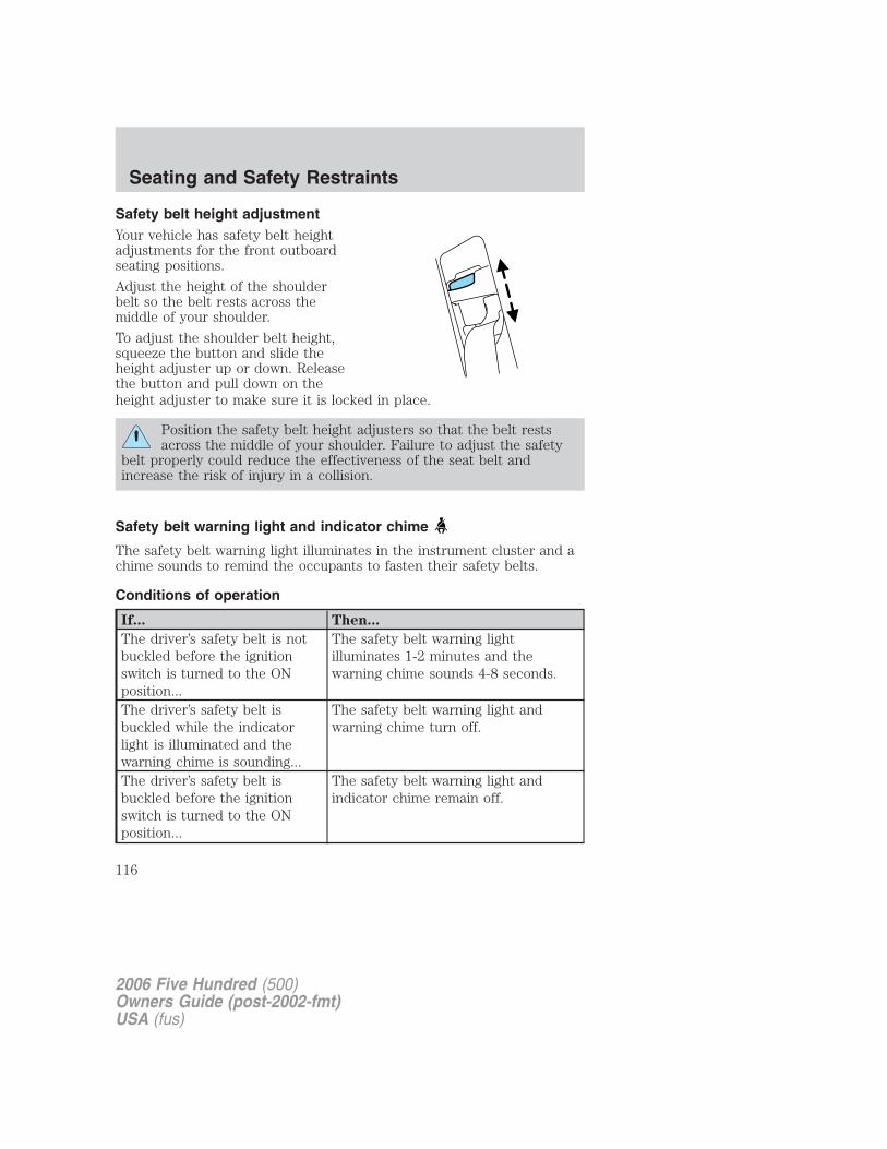
Safety belt height adjustmentYour vehicle has safety belt heightadjustments for the front outboardseating positions.
Adjust the height of the shoulderbelt so the belt rests across themiddle of your shoulder.
To adjust the shoulder belt height,squeeze the button and slide theheight adjuster up or down. Releasethe button and pull down on theheight adjuster to make sure it is locked in place.
Position the safety belt height adjusters so that the belt restsacross the middle of your shoulder. Failure to adjust the safety
belt properly could reduce the effectiveness of the seat belt andincrease the risk of injury in a collision.
Safety belt warning light and indicator chime
The safety belt warning light illuminates in the instrument cluster and achime sounds to remind the occupants to fasten their safety belts.
Conditions of operation
If... Then...
The driver’s safety belt is notbuckled before the ignitionswitch is turned to the ONposition...
The safety belt warning lightilluminates 1-2 minutes and thewarning chime sounds 4-8 seconds.
The driver’s safety belt isbuckled while the indicatorlight is illuminated and thewarning chime is sounding...
The safety belt warning light andwarning chime turn off.
The driver’s safety belt isbuckled before the ignitionswitch is turned to the ONposition...
The safety belt warning light andindicator chime remain off.
2006 Five Hundred (500)Owners Guide (post-2002-fmt)USA (fus)
Seating and Safety Restraints
116
BeltMinder�
The BeltMinder� feature is a supplemental warning to the safety beltwarning function. This feature provides additional reminders byintermittently sounding a chime and illuminating the safety belt warninglight in the instrument cluster when the driver’s and front passenger’ssafety belt is unbuckled.
The BeltMinder� feature uses information from the front passengersensing system to determine if a front seat passenger is present andtherefore potentially in need of a warning. To avoid activating theBeltMinder� feature for objects placed in the front passenger seat,warnings will only be given to large front seat occupants as determinedby the front passenger sensing system.
Both the driver’s and passenger’s safety belt usages are monitored andeither may activate the BeltMinder� feature. The warnings are the samefor the driver and the front passenger. If the BeltMinder� warnings haveexpired (warnings for approximately 5 minutes) for one occupant (driveror front passenger), the other occupant can still activate the BeltMinder�feature.
2006 Five Hundred (500)Owners Guide (post-2002-fmt)USA (fus)
Seating and Safety Restraints
117
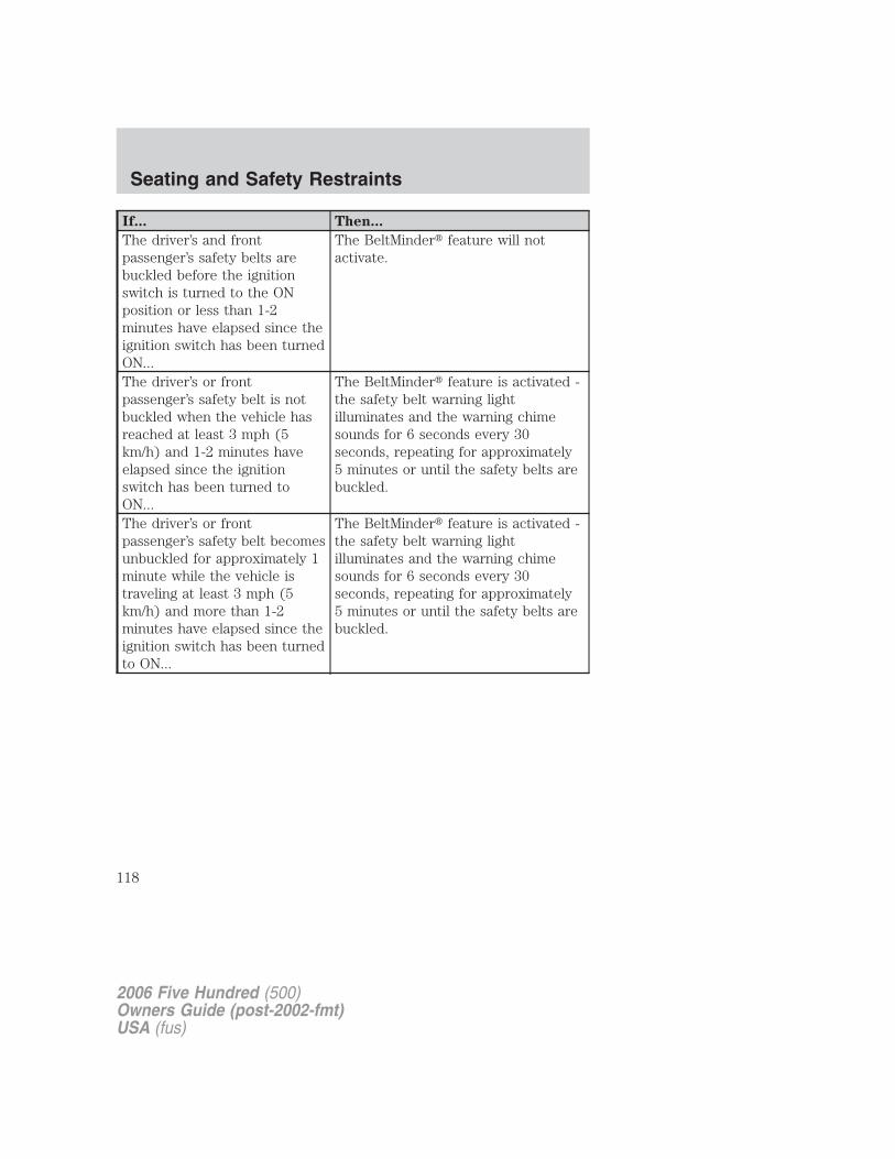
If... Then...
The driver’s and frontpassenger’s safety belts arebuckled before the ignitionswitch is turned to the ONposition or less than 1-2minutes have elapsed since theignition switch has been turnedON...
The BeltMinder� feature will notactivate.
The driver’s or frontpassenger’s safety belt is notbuckled when the vehicle hasreached at least 3 mph (5km/h) and 1-2 minutes haveelapsed since the ignitionswitch has been turned toON...
The BeltMinder� feature is activated -the safety belt warning lightilluminates and the warning chimesounds for 6 seconds every 30seconds, repeating for approximately5 minutes or until the safety belts arebuckled.
The driver’s or frontpassenger’s safety belt becomesunbuckled for approximately 1minute while the vehicle istraveling at least 3 mph (5km/h) and more than 1-2minutes have elapsed since theignition switch has been turnedto ON...
The BeltMinder� feature is activated -the safety belt warning lightilluminates and the warning chimesounds for 6 seconds every 30seconds, repeating for approximately5 minutes or until the safety belts arebuckled.
2006 Five Hundred (500)Owners Guide (post-2002-fmt)USA (fus)
Seating and Safety Restraints
118
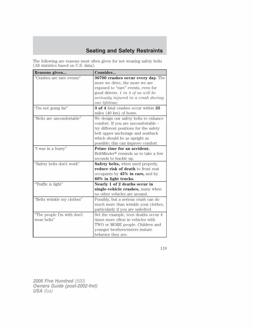
The following are reasons most often given for not wearing safety belts(All statistics based on U.S. data):
Reasons given... Consider...
“Crashes are rare events” 36700 crashes occur every day. Themore we drive, the more we areexposed to “rare” events, even forgood drivers. 1 in 4 of us will be
seriously injured in a crash during
our lifetime.
“I’m not going far” 3 of 4 fatal crashes occur within 25
miles (40 km) of home.“Belts are uncomfortable” We design our safety belts to enhance
comfort. If you are uncomfortable -try different positions for the safetybelt upper anchorage and seatbackwhich should be as upright aspossible; this can improve comfort.
“I was in a hurry” Prime time for an accident.
BeltMinder� reminds us to take a fewseconds to buckle up.
“Safety belts don’t work” Safety belts, when used properly,reduce risk of death to front seatoccupants by 45% in cars, and by60% in light trucks.
“Traffic is light” Nearly 1 of 2 deaths occur in
single-vehicle crashes, many whenno other vehicles are around.
“Belts wrinkle my clothes” Possibly, but a serious crash can domuch more than wrinkle your clothes,particularly if you are unbelted.
“The people I’m with don’twear belts”
Set the example, teen deaths occur 4times more often in vehicles withTWO or MORE people. Children andyounger brothers/sisters imitatebehavior they see.
2006 Five Hundred (500)Owners Guide (post-2002-fmt)USA (fus)
Seating and Safety Restraints
119
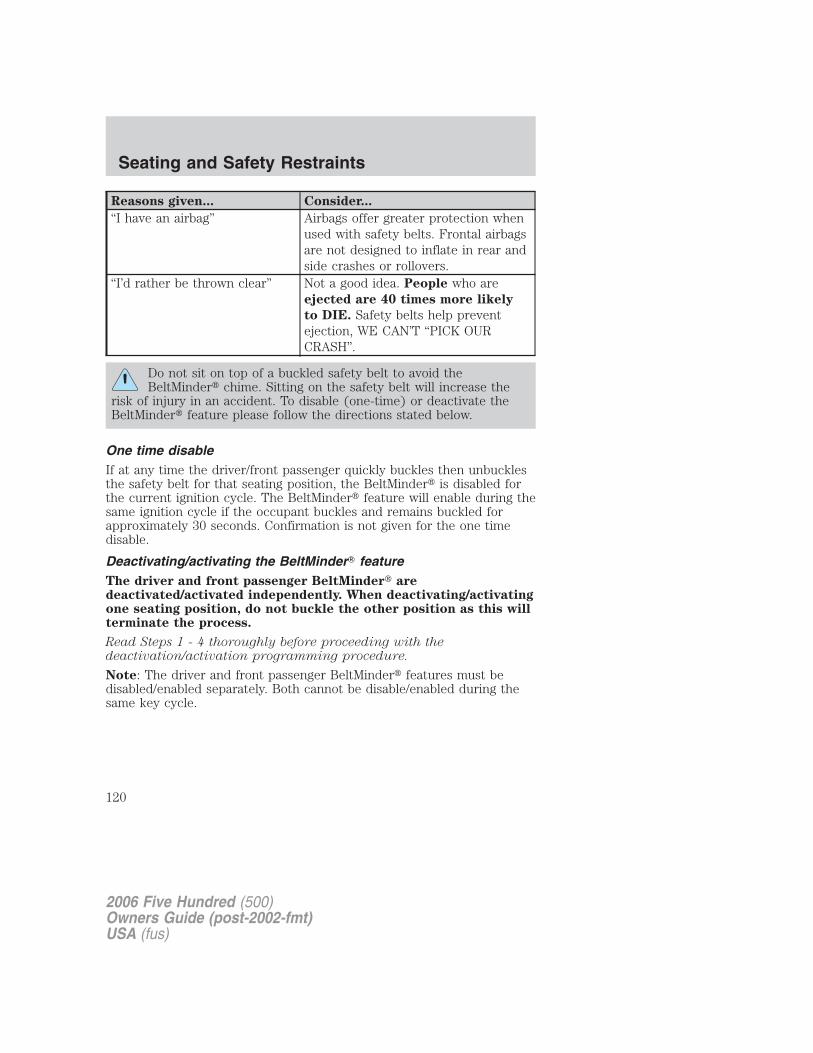
Reasons given... Consider...
“I have an airbag” Airbags offer greater protection whenused with safety belts. Frontal airbagsare not designed to inflate in rear andside crashes or rollovers.
“I’d rather be thrown clear” Not a good idea. People who areejected are 40 times more likely
to DIE. Safety belts help preventejection, WE CAN’T “PICK OURCRASH”.
Do not sit on top of a buckled safety belt to avoid theBeltMinder� chime. Sitting on the safety belt will increase the
risk of injury in an accident. To disable (one-time) or deactivate theBeltMinder� feature please follow the directions stated below.
One time disableIf at any time the driver/front passenger quickly buckles then unbucklesthe safety belt for that seating position, the BeltMinder� is disabled forthe current ignition cycle. The BeltMinder� feature will enable during thesame ignition cycle if the occupant buckles and remains buckled forapproximately 30 seconds. Confirmation is not given for the one timedisable.
Deactivating/activating the BeltMinder� featureThe driver and front passenger BeltMinder� aredeactivated/activated independently. When deactivating/activatingone seating position, do not buckle the other position as this willterminate the process.
Read Steps 1 - 4 thoroughly before proceeding with thedeactivation/activation programming procedure.
Note: The driver and front passenger BeltMinder� features must bedisabled/enabled separately. Both cannot be disable/enabled during thesame key cycle.
2006 Five Hundred (500)Owners Guide (post-2002-fmt)USA (fus)
Seating and Safety Restraints
120
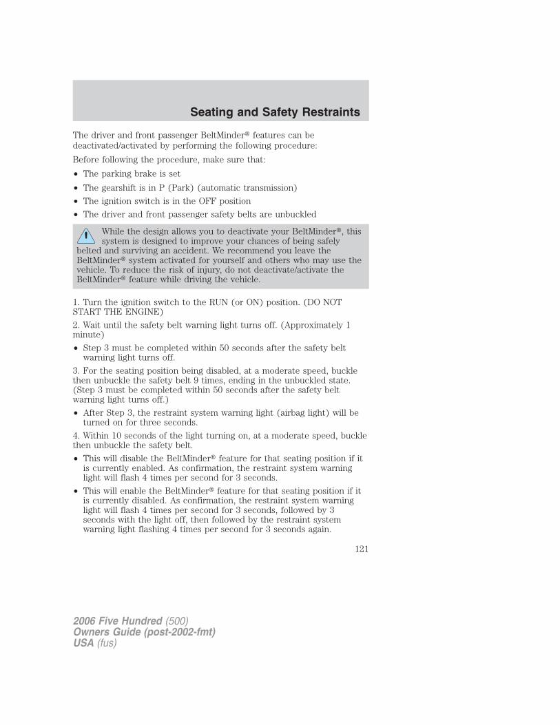
The driver and front passenger BeltMinder� features can bedeactivated/activated by performing the following procedure:
Before following the procedure, make sure that:
• The parking brake is set
• The gearshift is in P (Park) (automatic transmission)
• The ignition switch is in the OFF position
• The driver and front passenger safety belts are unbuckled
While the design allows you to deactivate your BeltMinder�, thissystem is designed to improve your chances of being safely
belted and surviving an accident. We recommend you leave theBeltMinder� system activated for yourself and others who may use thevehicle. To reduce the risk of injury, do not deactivate/activate theBeltMinder� feature while driving the vehicle.
1. Turn the ignition switch to the RUN (or ON) position. (DO NOTSTART THE ENGINE)
2. Wait until the safety belt warning light turns off. (Approximately 1minute)
• Step 3 must be completed within 50 seconds after the safety beltwarning light turns off.
3. For the seating position being disabled, at a moderate speed, bucklethen unbuckle the safety belt 9 times, ending in the unbuckled state.(Step 3 must be completed within 50 seconds after the safety beltwarning light turns off.)
• After Step 3, the restraint system warning light (airbag light) will beturned on for three seconds.
4. Within 10 seconds of the light turning on, at a moderate speed, bucklethen unbuckle the safety belt.
• This will disable the BeltMinder� feature for that seating position if itis currently enabled. As confirmation, the restraint system warninglight will flash 4 times per second for 3 seconds.
• This will enable the BeltMinder� feature for that seating position if itis currently disabled. As confirmation, the restraint system warninglight will flash 4 times per second for 3 seconds, followed by 3seconds with the light off, then followed by the restraint systemwarning light flashing 4 times per second for 3 seconds again.
2006 Five Hundred (500)Owners Guide (post-2002-fmt)USA (fus)
Seating and Safety Restraints
121
Safety belt extension assembly
If the safety belt is too short when fully extended, there is a 8 inch (20cm) safety belt extension assembly that can be added (part number611C22). This assembly can be obtained from an authorized dealer.
Use only extensions manufactured by the same supplier as the safetybelt. Manufacturer identification is located at the end of the webbing onthe label. Also, use the safety belt extension only if the safety belt is tooshort for you when fully extended.
Do not use extensions to change the fit of the shoulder beltacross the torso.
Safety belt maintenance
Inspect the safety belt systems periodically to make sure they workproperly and are not damaged. Inspect the safety belts to make surethere are no nicks, tears or cuts. Replace if necessary. All safety beltassemblies, including retractors, buckles, front safety belt buckleassemblies, buckle support assemblies (slide bar-if equipped), shoulderbelt height adjusters (if equipped), shoulder belt guide on seatback (ifequipped), child safety seat LATCH and tether anchors, and attachinghardware, should be inspected after a collision. Ford Motor Companyrecommends that all safety belt assemblies in use in vehicles involved ina collision be replaced. However, if the collision was minor and anauthorized dealer finds that the belts do not show damage and continueto operate properly, they do not need to be replaced. Safety beltassemblies not in use during a collision should also be inspected andreplaced if either damage or improper operation is noted.
Failure to inspect and if necessary replace the safety beltassembly under the above conditions could result in severe
personal injuries in the event of a collision.
For proper care of soiled safety belts, refer to Interior in the Cleaningchapter.
2006 Five Hundred (500)Owners Guide (post-2002-fmt)USA (fus)
Seating and Safety Restraints
122
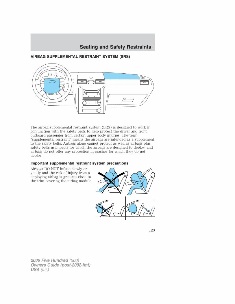
AIRBAG SUPPLEMENTAL RESTRAINT SYSTEM (SRS)
The airbag supplemental restraint system (SRS) is designed to work inconjunction with the safety belts to help protect the driver and frontoutboard passenger from certain upper body injuries. The term“supplemental restraint” means the airbags are intended as a supplementto the safety belts. Airbags alone cannot protect as well as airbags plussafety belts in impacts for which the airbags are designed to deploy, andairbags do not offer any protection in crashes for which they do notdeploy.
Important supplemental restraint system precautionsAirbags DO NOT inflate slowly orgently and the risk of injury from adeploying airbag is greatest close tothe trim covering the airbag module.
2006 Five Hundred (500)Owners Guide (post-2002-fmt)USA (fus)
Seating and Safety Restraints
123
All occupants of the vehicle, including the driver, should alwaysproperly wear their safety belts, even when an air bag
supplemental restraint system (SRS) is provided.
Always transport children 12 years old and under in the backseat and always properly use appropriate child restraints.
National Highway Traffic Safety Administration (NHTSA)recommends a minimum distance of at least 10 inches (25 cm)
between an occupant’s chest and the driver airbag module.
Never place your arm over the airbag module as a deployingairbag can result in serious arm fractures or other injuries.
Steps you can take to properly position yourself away from the airbag:
• Move your seat to the rear as far as you can while still reaching thepedals comfortably.
• Recline the seat slightly (one or two degrees) from the uprightposition.
Do not put anything on or over the airbag module. Placingobjects on or over the airbag inflation area may cause those
objects to be propelled by the airbag into your face and torso causingserious injury.
Do not attempt to service, repair, or modify the airbagsupplemental restraint system (SRS) or its fuses. See your
authorized dealer.
Modifying or adding equipment to the front end of the vehicle(including frame, bumper, front end body structure and tow
hooks) may affect the performance of the airbag system, increasing therisk of injury. Do not modify the front end of the vehicle.
2006 Five Hundred (500)Owners Guide (post-2002-fmt)USA (fus)
Seating and Safety Restraints
124
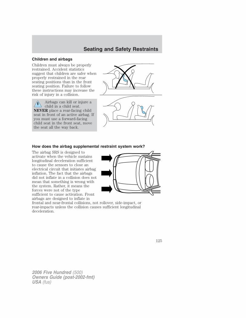
Children and airbagsChildren must always be properlyrestrained. Accident statisticssuggest that children are safer whenproperly restrained in the rearseating positions than in the frontseating position. Failure to followthese instructions may increase therisk of injury in a collision.
Airbags can kill or injure achild in a child seat.
NEVER place a rear-facing childseat in front of an active airbag. Ifyou must use a forward-facingchild seat in the front seat, movethe seat all the way back.
How does the airbag supplemental restraint system work?The airbag SRS is designed toactivate when the vehicle sustainslongitudinal deceleration sufficientto cause the sensors to close anelectrical circuit that initiates airbaginflation. The fact that the airbagsdid not inflate in a collision does notmean that something is wrong withthe system. Rather, it means theforces were not of the typesufficient to cause activation. Frontairbags are designed to inflate infrontal and near-frontal collisions, not rollover, side-impact, orrear-impacts unless the collision causes sufficient longitudinaldeceleration.
2006 Five Hundred (500)Owners Guide (post-2002-fmt)USA (fus)
Seating and Safety Restraints
125
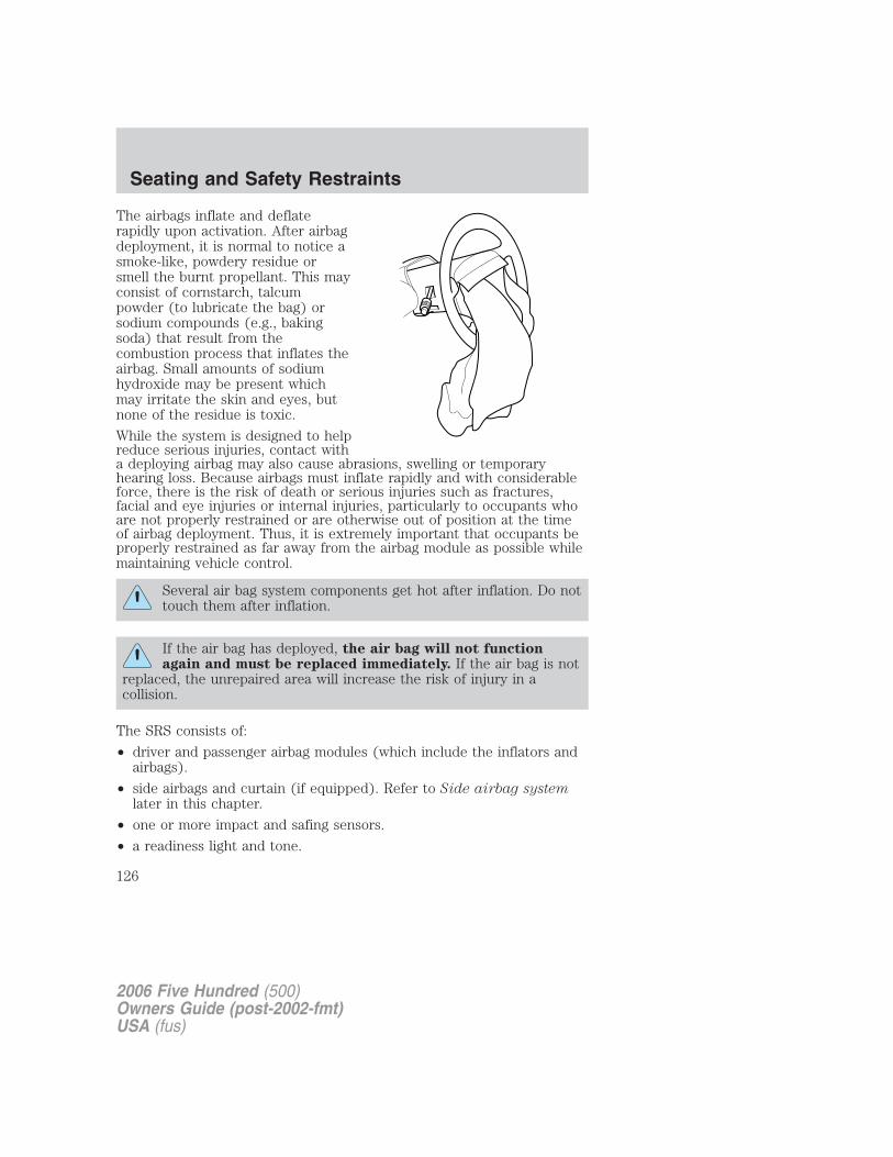
The airbags inflate and deflaterapidly upon activation. After airbagdeployment, it is normal to notice asmoke-like, powdery residue orsmell the burnt propellant. This mayconsist of cornstarch, talcumpowder (to lubricate the bag) orsodium compounds (e.g., bakingsoda) that result from thecombustion process that inflates theairbag. Small amounts of sodiumhydroxide may be present whichmay irritate the skin and eyes, butnone of the residue is toxic.
While the system is designed to helpreduce serious injuries, contact witha deploying airbag may also cause abrasions, swelling or temporaryhearing loss. Because airbags must inflate rapidly and with considerableforce, there is the risk of death or serious injuries such as fractures,facial and eye injuries or internal injuries, particularly to occupants whoare not properly restrained or are otherwise out of position at the timeof airbag deployment. Thus, it is extremely important that occupants beproperly restrained as far away from the airbag module as possible whilemaintaining vehicle control.
Several air bag system components get hot after inflation. Do nottouch them after inflation.
If the air bag has deployed, the air bag will not functionagain and must be replaced immediately. If the air bag is not
replaced, the unrepaired area will increase the risk of injury in acollision.
The SRS consists of:
• driver and passenger airbag modules (which include the inflators andairbags).
• side airbags and curtain (if equipped). Refer to Side airbag systemlater in this chapter.
• one or more impact and safing sensors.
• a readiness light and tone.
2006 Five Hundred (500)Owners Guide (post-2002-fmt)USA (fus)
Seating and Safety Restraints
126
• diagnostic module.
• and the electrical wiring which connects the components.
The diagnostic module monitors its own internal circuits and thesupplemental airbag electrical system wiring (including the impactsensors), the system wiring, the airbag system readiness light, the airbagback up power and the airbag ignitors.
Front passenger sensing systemThe front passenger sensing system is designed to meet the regulatoryrequirements of Federal Motor Vehicle Safety Standard (FMVSS) 208and is designed to disable (will not inflate) the front passenger’s frontalairbag under certain conditions.
The front passenger sensing system works with sensors that are part ofthe front passenger’s seat and safety belt. The sensors are designed todetect the presence of a properly seated occupant and determine if thefront passenger’s frontal airbag should be enabled (may inflate) ordisabled (will not inflate).
The front passenger sensing system will disable (will not inflate) thefront passenger’s frontal airbag if:
• the front passenger seat is unoccupied, or has small/medium objects inthe front seat,
• the system determines that an infant is present in a rear-facing infantseat that is installed according to the manufacturer’s instructions,
• the system determines that a small child is present in a forward-facingchild restraint that is installed according to the manufacturer’sinstructions,
• the system determines that a small child is present in a booster seat,
• a front passenger takes his/her weight off of the seat for a period oftime,
• a child or a small person occupies the front passenger seat.
For side airbag equipped vehicles, the front passenger sensing systemwill turn off the passenger seat side airbag if:
• the seat is empty and safety belt is unbuckled.
2006 Five Hundred (500)Owners Guide (post-2002-fmt)USA (fus)
Seating and Safety Restraints
127
The front passenger sensing systemuses a �passenger airbag off� or�pass airbag off� indicator which willilluminate and stay lit to remind youthat the front passenger frontal airbag is disabled. The indicator lamp islocated above the glove box on the instrument panel.Note: The indicator lamp will illuminate for a short period of time whenthe ignition is turned to the ON position to confirm it is functional.When the front passenger seat is not occupied (empty seat) or in theevent that the front passenger frontal airbag is enabled (may inflate), theindicator lamp will be unlit.The front passenger sensing system is designed to disable (will notinflate) the front passenger’s frontal airbag when a rear facing infantseat, a forward-facing child restraint, or a booster seat is detected.• When the front passenger sensing system disables (will not inflate)
the front passenger frontal airbag, the indicator lamp will illuminateand stay lit to remind you that the front passenger frontal airbag isdisabled.
• If the child restraint has been installed and the indicator lamp is notlit, then turn the vehicle off, remove the child restraint from thevehicle and reinstall the restraint following the child restraintmanufacturer’s instructions.
The front passenger sensing system is designed to enable (may inflate)the front passenger’s frontal airbag anytime the system senses that aperson of adult size is sitting properly in the front passenger seat.
• When the front passenger sensing system enables the front passengerfrontal airbag (may inflate), the indicator will be unlit and stay unlit.
If a person of adult size is sitting in the front passenger’s seat, but the�passenger airbag off� or �pass airbag off� indicator lamp is lit, it ispossible that the person isn’t sitting properly in the seat. If this happens:
• Turn the vehicle off and ask the person to place the seatback in thefull upright position.
• Have the person sit upright in the seat, centered on the seat cushion,with the person’s legs comfortably extended.
• Restart the vehicle and have the person remain in this position forabout two minutes. This will allow the system to detect that personand enable the passenger’s frontal airbag.
• If the indicator lamp remains lit even after this, the person should beadvised to ride in the rear seat.
2006 Five Hundred (500)Owners Guide (post-2002-fmt)USA (fus)
Seating and Safety Restraints
128
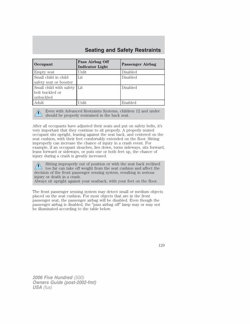
OccupantPass Airbag Off
Indicator LightPassenger Airbag
Empty seat Unlit DisabledSmall child in childsafety seat or booster
Lit Disabled
Small child with safetybelt buckled orunbuckled
Lit Disabled
Adult Unlit Enabled
Even with Advanced Restraints Systems, children 12 and undershould be properly restrained in the back seat.
After all occupants have adjusted their seats and put on safety belts, it’svery important that they continue to sit properly. A properly seatedoccupant sits upright, leaning against the seat back, and centered on theseat cushion, with their feet comfortably extended on the floor. Sittingimproperly can increase the chance of injury in a crash event. Forexample, if an occupant slouches, lies down, turns sideways, sits forward,leans forward or sideways, or puts one or both feet up, the chance ofinjury during a crash is greatly increased.
Sitting improperly out of position or with the seat back reclinedtoo far can take off weight from the seat cushion and affect the
decision of the front passenger sensing system, resulting in seriousinjury or death in a crash.Always sit upright against your seatback, with your feet on the floor.
The front passenger sensing system may detect small or medium objectsplaced on the seat cushion. For most objects that are in the frontpassenger seat, the passenger airbag will be disabled. Even though thepassenger airbag is disabled, the �pass airbag off� lamp may or may notbe illuminated according to the table below.
2006 Five Hundred (500)Owners Guide (post-2002-fmt)USA (fus)
Seating and Safety Restraints
129
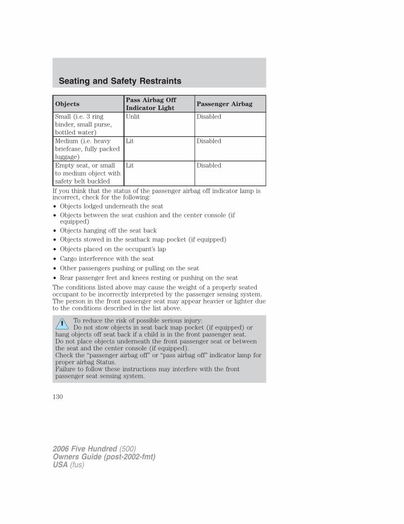
ObjectsPass Airbag Off
Indicator LightPassenger Airbag
Small (i.e. 3 ringbinder, small purse,bottled water)
Unlit Disabled
Medium (i.e. heavybriefcase, fully packedluggage)
Lit Disabled
Empty seat, or smallto medium object withsafety belt buckled
Lit Disabled
If you think that the status of the passenger airbag off indicator lamp isincorrect, check for the following:• Objects lodged underneath the seat• Objects between the seat cushion and the center console (if
equipped)• Objects hanging off the seat back• Objects stowed in the seatback map pocket (if equipped)
• Objects placed on the occupant’s lap
• Cargo interference with the seat
• Other passengers pushing or pulling on the seat
• Rear passenger feet and knees resting or pushing on the seat
The conditions listed above may cause the weight of a properly seatedoccupant to be incorrectly interpreted by the passenger sensing system.The person in the front passenger seat may appear heavier or lighter dueto the conditions described in the list above.
To reduce the risk of possible serious injury:Do not stow objects in seat back map pocket (if equipped) or
hang objects off seat back if a child is in the front passenger seat.Do not place objects underneath the front passenger seat or betweenthe seat and the center console (if equipped).Check the “passenger airbag off” or “pass airbag off” indicator lamp forproper airbag Status.Failure to follow these instructions may interfere with the frontpassenger seat sensing system.
2006 Five Hundred (500)Owners Guide (post-2002-fmt)USA (fus)
Seating and Safety Restraints
130

In case there is a problem with thefront passenger sensing system, theairbag readiness lamp in theinstrument cluster will stay lit.
If the airbag readiness lamp is lit, do the following:
The driver and/or adult passengers should check for any objects thatmay be lodged underneath the front passenger seat or cargo interferingwith the seat.
If objects are lodged and/or cargo is interfering with the seat; please takethe following steps to remove the obstruction:
• Pull the vehicle over.
• Turn the vehicle off.
• Driver and/or adult passengers should check for any objects lodgedunderneath the front passenger seat or cargo interfering with the seat.
• Remove the obstruction(s) (if found).
• Restart the vehicle.
• Wait at least 2 minutes and verify that the airbag readiness lamp is nolonger illuminated
• If the airbag readiness lamp remains illuminated, this may or may/notbe a problem due to the front passenger sensing system.
DO NOT attempt to repair or service the system; take your vehicleimmediately to an authorized dealer.
If it is necessary to modify an advanced front airbag system toaccommodate a person with disabilities, contact the Ford CustomerRelationship Center at the phone number shown in the CustomerAssistance chapter of this Owner’s Guide.
Any alteration/modification to the front passenger seat mayaffect the performance of the front passenger sensing system.
Determining if the system is operationalThe supplemental restraint system uses a warning indicator light in theinstrument cluster or a back-up tone to indicate the condition of thesystem. Refer to the Warning lights and chimes section in theInstrument Cluster chapter. Routine maintenance of the airbag is notrequired.
2006 Five Hundred (500)Owners Guide (post-2002-fmt)USA (fus)
Seating and Safety Restraints
131
A difficulty with the system is indicated by one or more of the following:
• The readiness light (same lightfor front and side airbag system)will either flash or stay lit.
• The readiness light will notilluminate immediately after ignition is turned on.
• A series of five beeps will be heard. The tone pattern will repeatperiodically until the problem and/or light are repaired.
If any of these things happen, even intermittently, have the supplementalrestraint system serviced at an authorized dealer immediately. Unlessserviced, the system may not function properly in the event of acollision.
Seat-mounted side airbag system (if equipped)
Do not place objects or mount equipment on or near the airbagcover on the side of the seatbacks of the front seats or in front
seat areas that may come into contact with a deploying airbag. Failureto follow these instructions may increase the risk of personal injury inthe event of a collision.
Do not use accessory seat covers. The use of accessory seatcovers may prevent the deployment of the side airbags and
increase the risk of injury in an accident.
Do not lean your head on the door. The side airbag could injureyou as it deploys from the side of the seatback.
Do not attempt to service, repair, or modify the airbag SRS, itsfuses or the seat cover on a seat containing an airbag. See your
authorized dealer.
All occupants of the vehicle should always wear their safety beltseven when an airbag SRS is provided.
2006 Five Hundred (500)Owners Guide (post-2002-fmt)USA (fus)
Seating and Safety Restraints
132
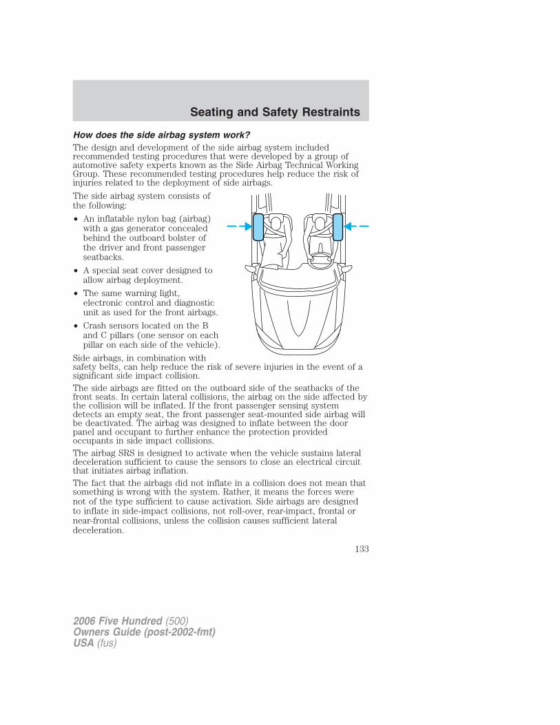
How does the side airbag system work?The design and development of the side airbag system includedrecommended testing procedures that were developed by a group ofautomotive safety experts known as the Side Airbag Technical WorkingGroup. These recommended testing procedures help reduce the risk ofinjuries related to the deployment of side airbags.
The side airbag system consists ofthe following:
• An inflatable nylon bag (airbag)with a gas generator concealedbehind the outboard bolster ofthe driver and front passengerseatbacks.
• A special seat cover designed toallow airbag deployment.
• The same warning light,electronic control and diagnosticunit as used for the front airbags.
• Crash sensors located on the Band C pillars (one sensor on eachpillar on each side of the vehicle).
Side airbags, in combination withsafety belts, can help reduce the risk of severe injuries in the event of asignificant side impact collision.The side airbags are fitted on the outboard side of the seatbacks of thefront seats. In certain lateral collisions, the airbag on the side affected bythe collision will be inflated. If the front passenger sensing systemdetects an empty seat, the front passenger seat-mounted side airbag willbe deactivated. The airbag was designed to inflate between the doorpanel and occupant to further enhance the protection providedoccupants in side impact collisions.The airbag SRS is designed to activate when the vehicle sustains lateraldeceleration sufficient to cause the sensors to close an electrical circuitthat initiates airbag inflation.The fact that the airbags did not inflate in a collision does not mean thatsomething is wrong with the system. Rather, it means the forces werenot of the type sufficient to cause activation. Side airbags are designedto inflate in side-impact collisions, not roll-over, rear-impact, frontal ornear-frontal collisions, unless the collision causes sufficient lateraldeceleration.
2006 Five Hundred (500)Owners Guide (post-2002-fmt)USA (fus)
Seating and Safety Restraints
133
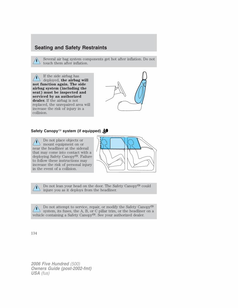
Several air bag system components get hot after inflation. Do nottouch them after inflation.
If the side airbag hasdeployed, the airbag will
not function again. The sideairbag system (including theseat) must be inspected andserviced by an authorizeddealer. If the airbag is notreplaced, the unrepaired area willincrease the risk of injury in acollision.
Safety Canopy� system (if equipped)
Do not place objects ormount equipment on or
near the headliner at the siderailthat may come into contact with adeploying Safety Canopy�. Failureto follow these instructions mayincrease the risk of personal injuryin the event of a collision.
Do not lean your head on the door. The Safety Canopy� couldinjure you as it deploys from the headliner.
Do not attempt to service, repair, or modify the Safety Canopy�system, its fuses, the A, B, or C pillar trim, or the headliner on a
vehicle containing a Safety Canopy�. See your authorized dealer.
2006 Five Hundred (500)Owners Guide (post-2002-fmt)USA (fus)
Seating and Safety Restraints
134
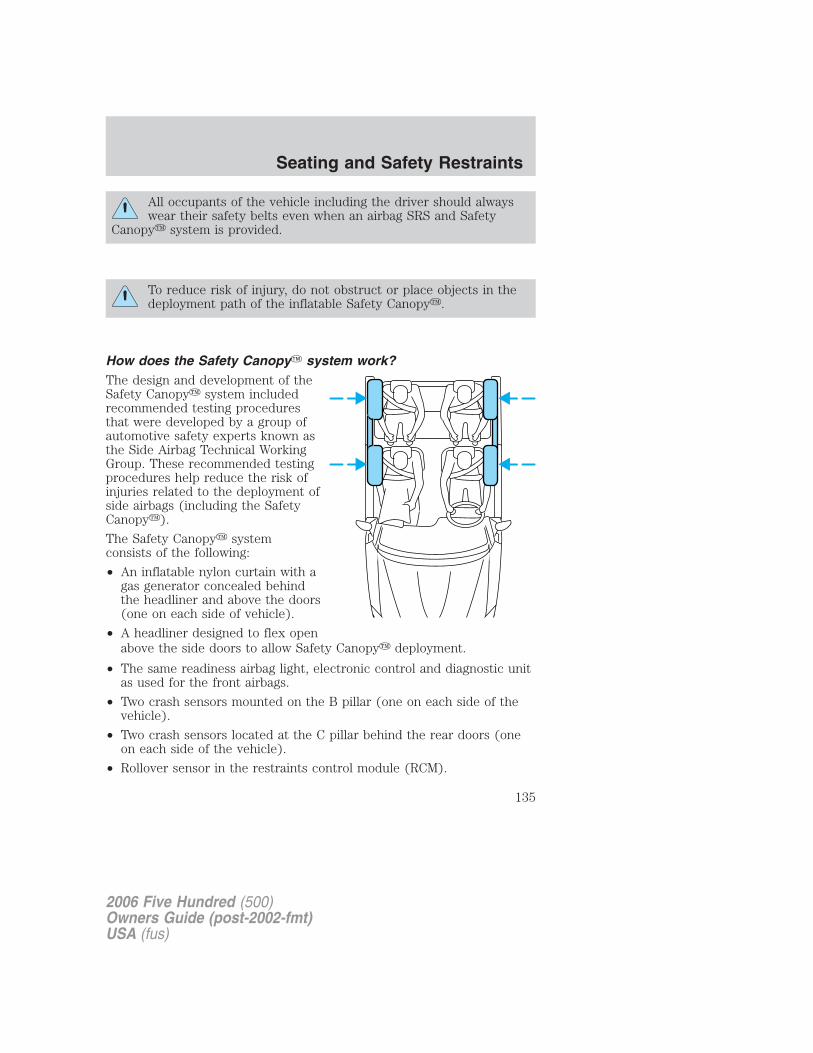
All occupants of the vehicle including the driver should alwayswear their safety belts even when an airbag SRS and Safety
Canopy� system is provided.
To reduce risk of injury, do not obstruct or place objects in thedeployment path of the inflatable Safety Canopy�.
How does the Safety Canopy� system work?The design and development of theSafety Canopy� system includedrecommended testing proceduresthat were developed by a group ofautomotive safety experts known asthe Side Airbag Technical WorkingGroup. These recommended testingprocedures help reduce the risk ofinjuries related to the deployment ofside airbags (including the SafetyCanopy�).
The Safety Canopy� systemconsists of the following:
• An inflatable nylon curtain with agas generator concealed behindthe headliner and above the doors(one on each side of vehicle).
• A headliner designed to flex openabove the side doors to allow Safety Canopy� deployment.
• The same readiness airbag light, electronic control and diagnostic unitas used for the front airbags.
• Two crash sensors mounted on the B pillar (one on each side of thevehicle).
• Two crash sensors located at the C pillar behind the rear doors (oneon each side of the vehicle).
• Rollover sensor in the restraints control module (RCM).
2006 Five Hundred (500)Owners Guide (post-2002-fmt)USA (fus)
Seating and Safety Restraints
135
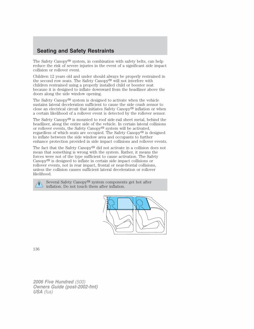
The Safety Canopy� system, in combination with safety belts, can helpreduce the risk of severe injuries in the event of a significant side impactcollision or rollover event.
Children 12 years old and under should always be properly restrained inthe second row seats. The Safety Canopy� will not interfere withchildren restrained using a properly installed child or booster seatbecause it is designed to inflate downward from the headliner above thedoors along the side window opening.
The Safety Canopy� system is designed to activate when the vehiclesustains lateral deceleration sufficient to cause the side crash sensor toclose an electrical circuit that initiates Safety Canopy� inflation or whena certain likelihood of a rollover event is detected by the rollover sensor.
The Safety Canopy� is mounted to roof side-rail sheet metal, behind theheadliner, along the entire side of the vehicle. In certain lateral collisionsor rollover events, the Safety Canopy� system will be activated,regardless of which seats are occupied. The Safety Canopy� is designedto inflate between the side window area and occupants to furtherenhance protection provided in side impact collisions and rollover events.
The fact that the Safety Canopy� did not activate in a collision does notmean that something is wrong with the system. Rather, it means theforces were not of the type sufficient to cause activation. The SafetyCanopy� is designed to inflate in certain side impact collisions orrollover events, not in rear impact, frontal or near-frontal collisions,unless the collision causes sufficient lateral deceleration or rolloverlikelihood.
Several Safety Canopy� system components get hot afterinflation. Do not touch them after inflation.
2006 Five Hundred (500)Owners Guide (post-2002-fmt)USA (fus)
Seating and Safety Restraints
136
If the Safety Canopy� system has deployed, the SafetyCanopy� will not function again unless replaced. The
Safety Canopy� system (including the A, B, and C pillar trim)must be inspected and serviced by an authorized dealer. If theSafety Canopy� is not replaced, the unrepaired area will increase therisk of injury in a collision.
Determining if the system is operationalThe SRS uses a readiness light in the instrument cluster or a tone toindicate the condition of the system. Refer to the Airbag readinesssection in the Instrument Cluster chapter. Routine maintenance of theairbag is not required.
Any difficulty with the system is indicated by one or more of thefollowing:
• The readiness airbag light (same light as for front airbag system) willeither flash or stay lit.
• The readiness light will not illuminate immediately after ignition isturned on.
• A series of five beeps will be heard. The tone pattern will repeatperiodically until the problem and light are repaired.
If any of these things happen, even intermittently, have the SRS servicedat your an authorized dealer immediately. Unless serviced, the systemmay not function properly in the event of a collision or rollover event.
Disposal of airbags and airbag equipped vehiclesFor disposal of airbags or airbag equipped vehicles, see your authorizeddealer . Airbags MUST BE disposed of by qualified personnel.
SAFETY RESTRAINTS FOR CHILDRENSee the following sections for directions on how to properly use safetyrestraints for children. Also see Airbag supplemental restraint system(SRS) in this chapter for special instructions about using airbags.
Important child restraint precautionsYou are required by law to use safety restraints for children in the U.S.and Canada. If small children (generally children who are four years oldor younger and who weigh 40 lb. [18 kg] or less) ride in your vehicle, you
2006 Five Hundred (500)Owners Guide (post-2002-fmt)USA (fus)
Seating and Safety Restraints
137

must put them in safety seats made especially for children. Many statesrequire that children use approved booster seats until they are eightyears old. Check your local and state or provincial laws for specificrequirements regarding the safety of children in your vehicle. Whenpossible, always place children under age 12 in the rear seat of yourvehicle. Accident statistics suggest that children are safer when properlyrestrained in the rear seating positions than in the front seating position.
Never let a passenger hold a child on his or her lap while thevehicle is moving. The passenger cannot protect the child from
injury in a collision.
Always follow the instructions and warnings that come with any infant orchild restraint you might use.
Children and safety beltsIf the child is the proper size, restrain the child in a safety seat. Childrenwho are too large for child safety seats (as specified by your child safetyseat manufacturer) should always wear safety belts.Follow all the important safety restraint and airbag precautions thatapply to adult passengers in your vehicle.If the shoulder belt portion of a combination lap and shoulder belt canbe positioned so it does not cross or rest in front of the child’s face orneck, the child should wear the lap and shoulder belt. Moving the childcloser to the center of the vehicle may help provide a good shoulder beltfit.
Do not leave children, unreliable adults, or pets unattended inyour vehicle.
Child booster seatsChildren outgrow a typical convertible or toddler seat when they weigh40 lb. (18 kg) and are around 4 years of age. Although the lap/shoulderbelt will provide some protection, these children are still too small forlap/shoulder belts to fit properly, which could increase the risk of seriousinjury in a crash.
To improve the fit of both the lap and shoulder belt on children whohave outgrown child safety seats, Ford Motor Company recommends useof a belt-positioning booster.
Booster seats position a child so that safety belts fit better. They lift thechild up so that the lap belt rests low across the hips and the knees
2006 Five Hundred (500)Owners Guide (post-2002-fmt)USA (fus)
Seating and Safety Restraints
138
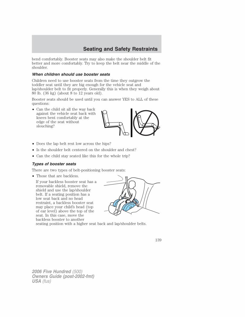
bend comfortably. Booster seats may also make the shoulder belt fitbetter and more comfortably. Try to keep the belt near the middle of theshoulder.
When children should use booster seats
Children need to use booster seats from the time they outgrow thetoddler seat until they are big enough for the vehicle seat andlap/shoulder belt to fit properly. Generally this is when they weigh about80 lb. (36 kg) (about 8 to 12 years old).
Booster seats should be used until you can answer YES to ALL of thesequestions:
• Can the child sit all the way backagainst the vehicle seat back withknees bent comfortably at theedge of the seat withoutslouching?
• Does the lap belt rest low across the hips?
• Is the shoulder belt centered on the shoulder and chest?
• Can the child stay seated like this for the whole trip?
Types of booster seats
There are two types of belt-positioning booster seats:
• Those that are backless.
If your backless booster seat has aremovable shield, remove theshield and use the lap/shoulderbelt. If a seating position has alow seat back and no headrestraint, a backless booster seatmay place your child’s head (topof ear level) above the top of theseat. In this case, move thebackless booster to anotherseating position with a higher seat back and lap/shoulder belts.
2006 Five Hundred (500)Owners Guide (post-2002-fmt)USA (fus)
Seating and Safety Restraints
139
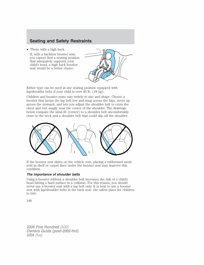
• Those with a high back.
If, with a backless booster seat,you cannot find a seating positionthat adequately supports yourchild’s head, a high back boosterseat would be a better choice.
Either type can be used at any seating position equipped withlap/shoulder belts if your child is over 40 lb. (18 kg).
Children and booster seats vary widely in size and shape. Choose abooster that keeps the lap belt low and snug across the hips, never upacross the stomach, and lets you adjust the shoulder belt to cross thechest and rest snugly near the center of the shoulder. The drawingsbelow compare the ideal fit (center) to a shoulder belt uncomfortablyclose to the neck and a shoulder belt that could slip off the shoulder.
If the booster seat slides on the vehicle seat, placing a rubberized meshsold as shelf or carpet liner under the booster seat may improve thiscondition.
The importance of shoulder beltsUsing a booster without a shoulder belt increases the risk of a child’shead hitting a hard surface in a collision. For this reason, you shouldnever use a booster seat with a lap belt only. It is best to use a boosterseat with lap/shoulder belts in the back seat- the safest place for childrento ride.
2006 Five Hundred (500)Owners Guide (post-2002-fmt)USA (fus)
Seating and Safety Restraints
140
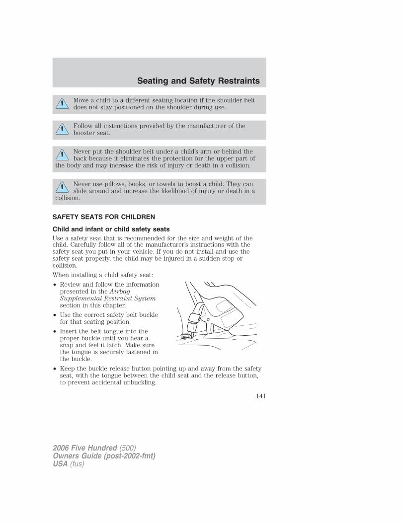
Move a child to a different seating location if the shoulder beltdoes not stay positioned on the shoulder during use.
Follow all instructions provided by the manufacturer of thebooster seat.
Never put the shoulder belt under a child’s arm or behind theback because it eliminates the protection for the upper part of
the body and may increase the risk of injury or death in a collision.
Never use pillows, books, or towels to boost a child. They canslide around and increase the likelihood of injury or death in a
collision.
SAFETY SEATS FOR CHILDREN
Child and infant or child safety seatsUse a safety seat that is recommended for the size and weight of thechild. Carefully follow all of the manufacturer’s instructions with thesafety seat you put in your vehicle. If you do not install and use thesafety seat properly, the child may be injured in a sudden stop orcollision.
When installing a child safety seat:
• Review and follow the informationpresented in the AirbagSupplemental Restraint Systemsection in this chapter.
• Use the correct safety belt bucklefor that seating position.
• Insert the belt tongue into theproper buckle until you hear asnap and feel it latch. Make surethe tongue is securely fastened inthe buckle.
• Keep the buckle release button pointing up and away from the safetyseat, with the tongue between the child seat and the release button,to prevent accidental unbuckling.
2006 Five Hundred (500)Owners Guide (post-2002-fmt)USA (fus)
Seating and Safety Restraints
141
• Place seat back in upright position.
• Put the safety belt in the automatic locking mode. Refer to Automatic
locking mode.
• LATCH lower anchors are recommended for use by children up to 48lb (22 kg) in a child restraint. Top tether anchors can be used forchildren up to 60 lb (27 kg) in a child restraint, and to provide uppertorso restraint for children up to 80 lb (36 kg) using an upper torsoharness and a belt-positioning booster.
Ford Motor Company recommends the use of a child safety seat having atop tether strap. Install the child safety seat in a seating position withLATCH and tether anchors. For more information on top tether strapsand anchors, refer to Attaching safety seats with tether straps in thischapter. For more information of LATCH anchors refer to Attaching
safety seats with LATCH (Lower Anchors and Tethers for Children)
attachments in this chapter.
Carefully follow all of the manufacturer’s instructions includedwith the safety seat you put in your vehicle. If you do not install
and use the safety seat properly, the child may be injured in a suddenstop or collision.
Rear-facing child seats or infant carriers should never be placedin front of an active passenger airbag.
Installing child safety seats with combination lap and shoulderbelts
Airbags can kill or injure a child in a child seat. NEVER place arear-facing child seat in front of an active airbag. If you must use
a forward-facing child seat in the front seat, move the seat all the wayback.
Children 12 and under should be properly restrained in the rearseat whenever possible.
2006 Five Hundred (500)Owners Guide (post-2002-fmt)USA (fus)
Seating and Safety Restraints
142
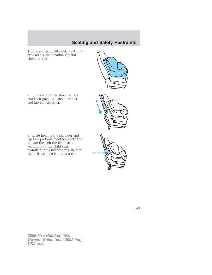
1. Position the child safety seat in aseat with a combination lap andshoulder belt.
2. Pull down on the shoulder beltand then grasp the shoulder beltand lap belt together.
3. While holding the shoulder andlap belt portions together, route thetongue through the child seataccording to the child seatmanufacturer’s instructions. Be surethe belt webbing is not twisted.
2006 Five Hundred (500)Owners Guide (post-2002-fmt)USA (fus)
Seating and Safety Restraints
143
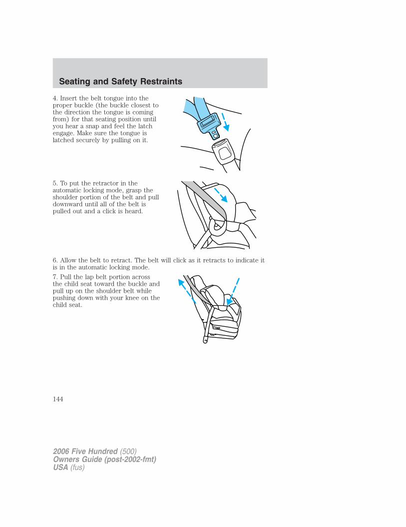
4. Insert the belt tongue into theproper buckle (the buckle closest tothe direction the tongue is comingfrom) for that seating position untilyou hear a snap and feel the latchengage. Make sure the tongue islatched securely by pulling on it.
5. To put the retractor in theautomatic locking mode, grasp theshoulder portion of the belt and pulldownward until all of the belt ispulled out and a click is heard.
6. Allow the belt to retract. The belt will click as it retracts to indicate itis in the automatic locking mode.
7. Pull the lap belt portion acrossthe child seat toward the buckle andpull up on the shoulder belt whilepushing down with your knee on thechild seat.
2006 Five Hundred (500)Owners Guide (post-2002-fmt)USA (fus)
Seating and Safety Restraints
144
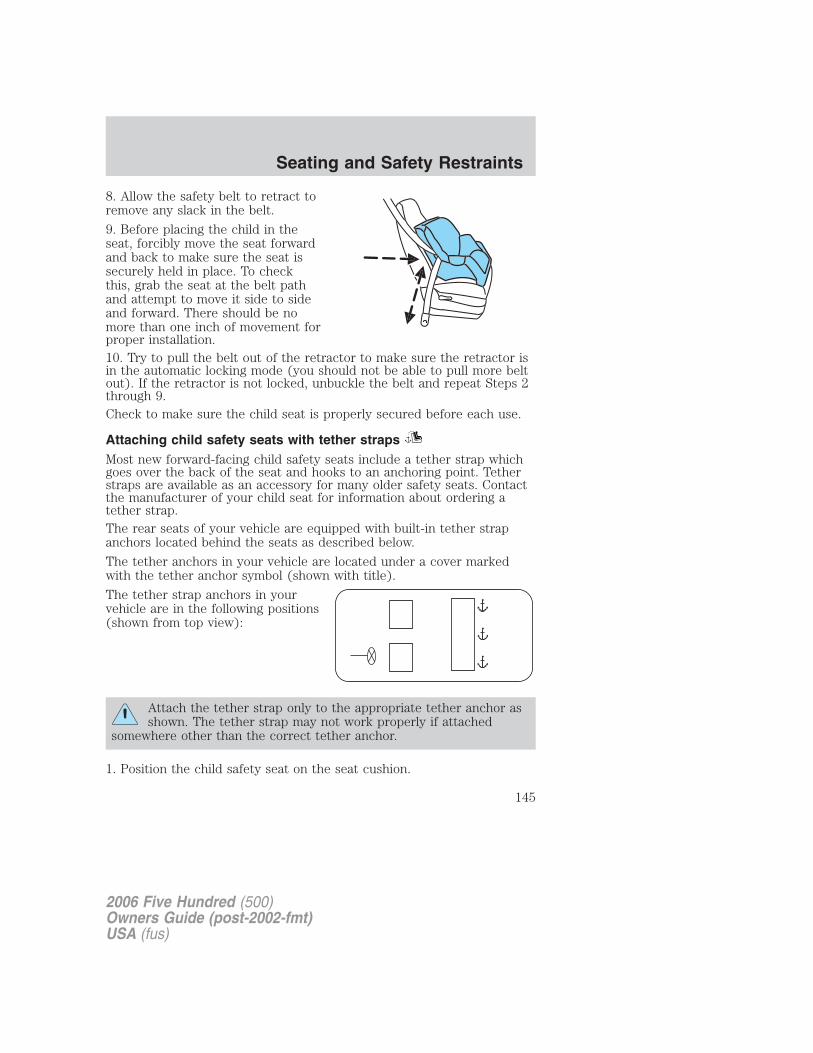
8. Allow the safety belt to retract toremove any slack in the belt.
9. Before placing the child in theseat, forcibly move the seat forwardand back to make sure the seat issecurely held in place. To checkthis, grab the seat at the belt pathand attempt to move it side to sideand forward. There should be nomore than one inch of movement forproper installation.10. Try to pull the belt out of the retractor to make sure the retractor isin the automatic locking mode (you should not be able to pull more beltout). If the retractor is not locked, unbuckle the belt and repeat Steps 2through 9.Check to make sure the child seat is properly secured before each use.
Attaching child safety seats with tether strapsMost new forward-facing child safety seats include a tether strap whichgoes over the back of the seat and hooks to an anchoring point. Tetherstraps are available as an accessory for many older safety seats. Contactthe manufacturer of your child seat for information about ordering atether strap.The rear seats of your vehicle are equipped with built-in tether strapanchors located behind the seats as described below.
The tether anchors in your vehicle are located under a cover markedwith the tether anchor symbol (shown with title).
The tether strap anchors in yourvehicle are in the following positions(shown from top view):
Attach the tether strap only to the appropriate tether anchor asshown. The tether strap may not work properly if attached
somewhere other than the correct tether anchor.
1. Position the child safety seat on the seat cushion.
2006 Five Hundred (500)Owners Guide (post-2002-fmt)USA (fus)
Seating and Safety Restraints
145
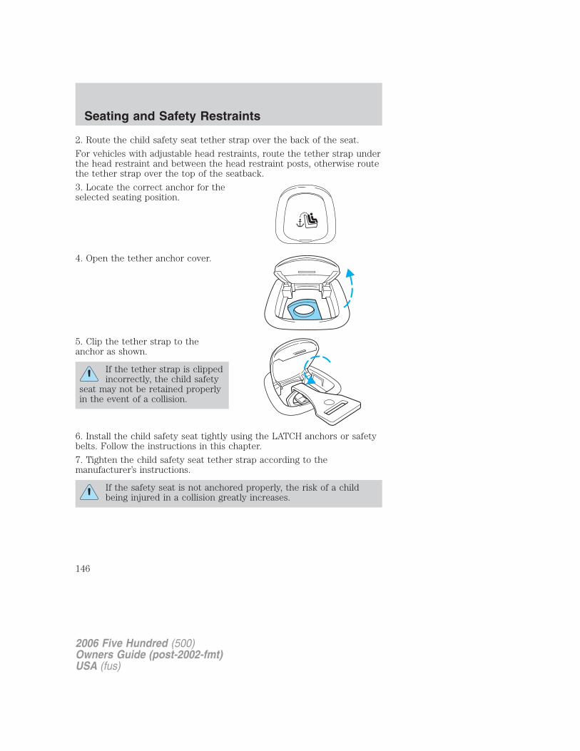
2. Route the child safety seat tether strap over the back of the seat.
For vehicles with adjustable head restraints, route the tether strap underthe head restraint and between the head restraint posts, otherwise routethe tether strap over the top of the seatback.
3. Locate the correct anchor for theselected seating position.
4. Open the tether anchor cover.
5. Clip the tether strap to theanchor as shown.
If the tether strap is clippedincorrectly, the child safety
seat may not be retained properlyin the event of a collision.
6. Install the child safety seat tightly using the LATCH anchors or safetybelts. Follow the instructions in this chapter.
7. Tighten the child safety seat tether strap according to themanufacturer’s instructions.
If the safety seat is not anchored properly, the risk of a childbeing injured in a collision greatly increases.
2006 Five Hundred (500)Owners Guide (post-2002-fmt)USA (fus)
Seating and Safety Restraints
146
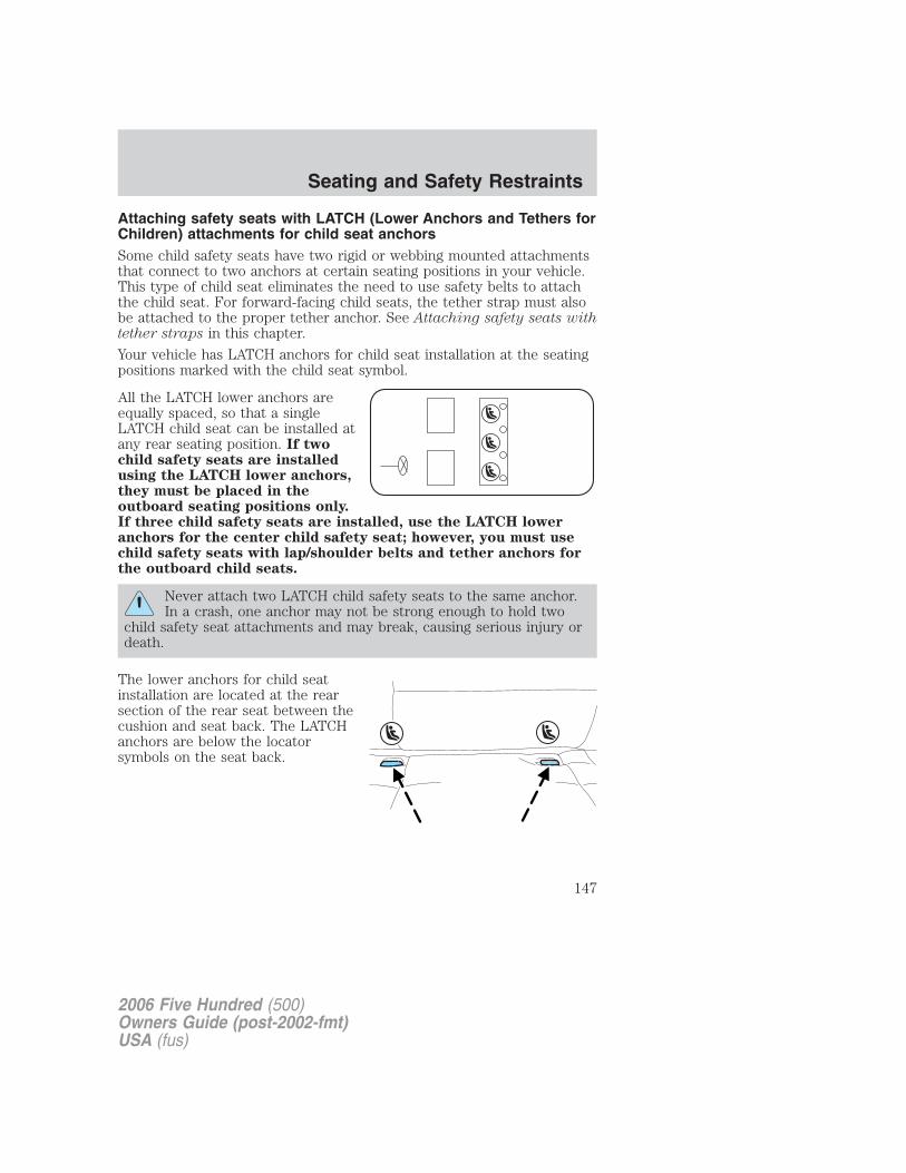
Attaching safety seats with LATCH (Lower Anchors and Tethers forChildren) attachments for child seat anchorsSome child safety seats have two rigid or webbing mounted attachmentsthat connect to two anchors at certain seating positions in your vehicle.This type of child seat eliminates the need to use safety belts to attachthe child seat. For forward-facing child seats, the tether strap must alsobe attached to the proper tether anchor. See Attaching safety seats withtether straps in this chapter.
Your vehicle has LATCH anchors for child seat installation at the seatingpositions marked with the child seat symbol.
All the LATCH lower anchors areequally spaced, so that a singleLATCH child seat can be installed atany rear seating position. If twochild safety seats are installedusing the LATCH lower anchors,they must be placed in theoutboard seating positions only.If three child safety seats are installed, use the LATCH loweranchors for the center child safety seat; however, you must usechild safety seats with lap/shoulder belts and tether anchors forthe outboard child seats.
Never attach two LATCH child safety seats to the same anchor.In a crash, one anchor may not be strong enough to hold two
child safety seat attachments and may break, causing serious injury ordeath.
The lower anchors for child seatinstallation are located at the rearsection of the rear seat between thecushion and seat back. The LATCHanchors are below the locatorsymbols on the seat back.
2006 Five Hundred (500)Owners Guide (post-2002-fmt)USA (fus)
Seating and Safety Restraints
147
Follow the child seat manufacturer’s instructions to properly install achild seat with LATCH attachments.
Attach LATCH lower attachments of the child seat only to theanchors shown.
If you install a child seat with rigid LATCH attachments, do not tightenthe tether strap enough to lift the child seat off the vehicle seat cushionwhen the child is seated in it. Keep the tether strap just snug withoutlifting the front of the child seat. Keeping the child seat just touching thevehicle seat gives the best protection in a severe crash.
Each time you use the safety seat, check that the seat is properlyattached to the lower anchors and tether anchor. Try to tilt the childseat from side to side. Also try to tug the seat forward. Check to see ifthe anchors hold the seat in place.
If the safety seat is not anchored properly, the risk of a childbeing injured in a crash greatly increases.
2006 Five Hundred (500)Owners Guide (post-2002-fmt)USA (fus)
Seating and Safety Restraints
148
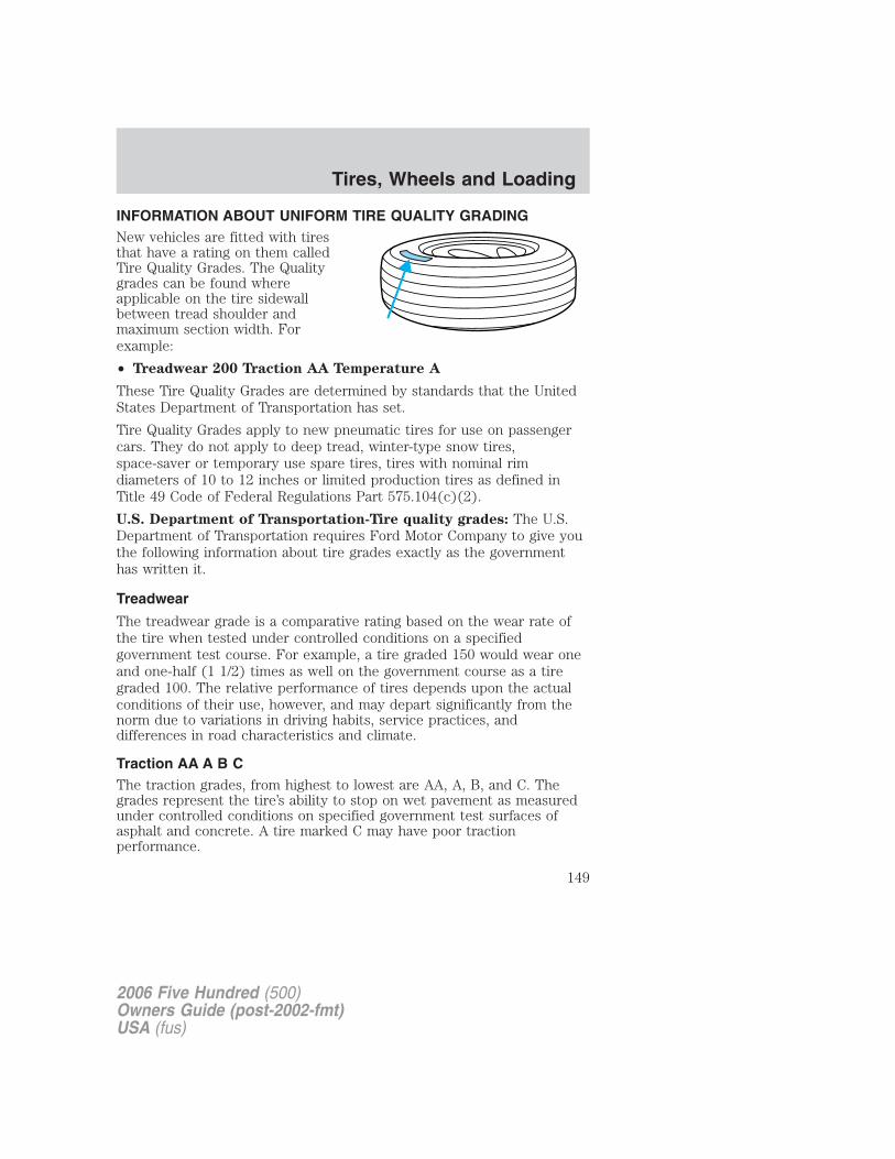
INFORMATION ABOUT UNIFORM TIRE QUALITY GRADINGNew vehicles are fitted with tiresthat have a rating on them calledTire Quality Grades. The Qualitygrades can be found whereapplicable on the tire sidewallbetween tread shoulder andmaximum section width. Forexample:
• Treadwear 200 Traction AA Temperature A
These Tire Quality Grades are determined by standards that the UnitedStates Department of Transportation has set.
Tire Quality Grades apply to new pneumatic tires for use on passengercars. They do not apply to deep tread, winter-type snow tires,space-saver or temporary use spare tires, tires with nominal rimdiameters of 10 to 12 inches or limited production tires as defined inTitle 49 Code of Federal Regulations Part 575.104(c)(2).
U.S. Department of Transportation-Tire quality grades: The U.S.Department of Transportation requires Ford Motor Company to give youthe following information about tire grades exactly as the governmenthas written it.
Treadwear
The treadwear grade is a comparative rating based on the wear rate ofthe tire when tested under controlled conditions on a specifiedgovernment test course. For example, a tire graded 150 would wear oneand one-half (1 1/2) times as well on the government course as a tiregraded 100. The relative performance of tires depends upon the actualconditions of their use, however, and may depart significantly from thenorm due to variations in driving habits, service practices, anddifferences in road characteristics and climate.
Traction AA A B CThe traction grades, from highest to lowest are AA, A, B, and C. Thegrades represent the tire’s ability to stop on wet pavement as measuredunder controlled conditions on specified government test surfaces ofasphalt and concrete. A tire marked C may have poor tractionperformance.
2006 Five Hundred (500)Owners Guide (post-2002-fmt)USA (fus)
Tires, Wheels and Loading
149
The traction grade assigned to this tire is based onstraight-ahead braking traction tests, and does not include
acceleration, cornering, hydroplaning or peak traction characteristics.
Temperature A B CThe temperature grades are A (the highest), B and C, representing the tire’sresistance to the generation of heat and its ability to dissipate heat whentested under controlled conditions on a specified indoor laboratory testwheel. Sustained high temperature can cause the material of the tire todegenerate and reduce tire life, and excessive temperature can lead tosudden tire failure. The grade C corresponds to a level of performance whichall passenger car tires must meet under the Federal Motor Vehicle SafetyStandard No. 109. Grades B and A represent higher levels of performance onthe laboratory test wheel than the minimum required by law.
The temperature grade for this tire is established for a tire thatis properly inflated and not overloaded. Excessive speed,
underinflation, or excessive loading, either separately or incombination, can cause heat buildup and possible tire failure.
TIRESTires are designed to give many thousands of miles of service, but theymust be maintained in order to get the maximum benefit from them.
Glossary of tire terminology• Tire label: A label showing the OE (Original Equipment) tire sizes,
recommended inflation pressure and the maximum weight the vehiclecan carry.
• Tire Identification Number (TIN): A number on the sidewall ofeach tire providing information about the tire brand andmanufacturing plant, tire size and date of manufacture. Also referredto as DOT code.
• Inflation pressure: A measure of the amount of air in a tire.
• Standard load: A class of P-metric or Metric tires designed to carry amaximum load at 35 psi [37 psi (2.5 bar) for Metric tires]. Increasingthe inflation pressure beyond this pressure will not increase the tire’sload carrying capability.
• Extra load: A class of P-metric or Metric tires designed to carry aheavier maximum load at 41 psi [43 psi (2.9 bar) for Metric tires].
2006 Five Hundred (500)Owners Guide (post-2002-fmt)USA (fus)
Tires, Wheels and Loading
150
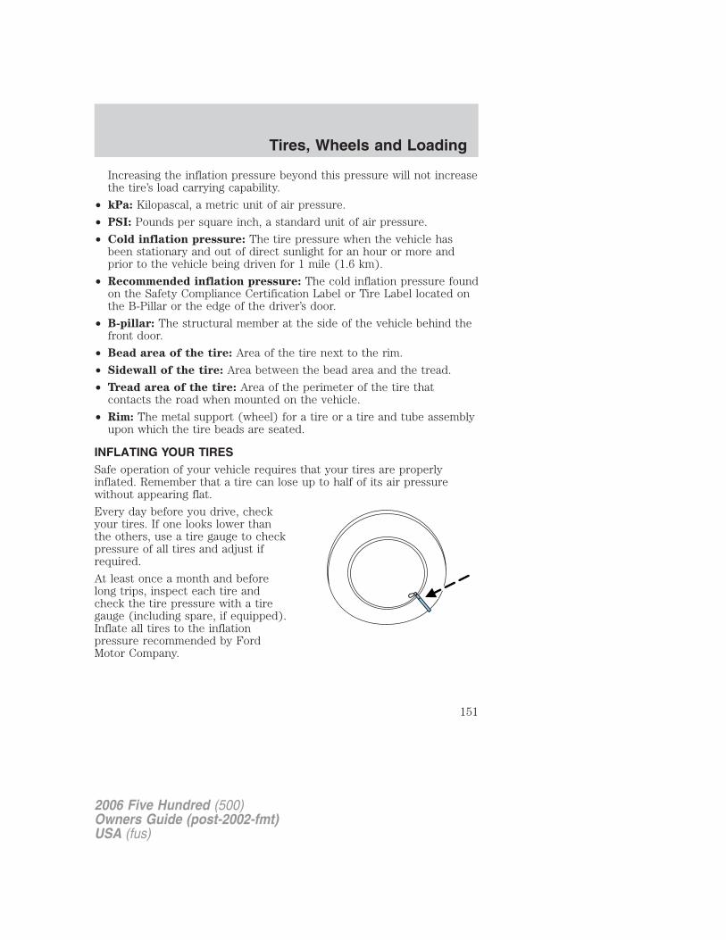
Increasing the inflation pressure beyond this pressure will not increasethe tire’s load carrying capability.
• kPa: Kilopascal, a metric unit of air pressure.
• PSI: Pounds per square inch, a standard unit of air pressure.
• Cold inflation pressure: The tire pressure when the vehicle hasbeen stationary and out of direct sunlight for an hour or more andprior to the vehicle being driven for 1 mile (1.6 km).
• Recommended inflation pressure: The cold inflation pressure foundon the Safety Compliance Certification Label or Tire Label located onthe B-Pillar or the edge of the driver’s door.
• B-pillar: The structural member at the side of the vehicle behind thefront door.
• Bead area of the tire: Area of the tire next to the rim.
• Sidewall of the tire: Area between the bead area and the tread.
• Tread area of the tire: Area of the perimeter of the tire thatcontacts the road when mounted on the vehicle.
• Rim: The metal support (wheel) for a tire or a tire and tube assemblyupon which the tire beads are seated.
INFLATING YOUR TIRESSafe operation of your vehicle requires that your tires are properlyinflated. Remember that a tire can lose up to half of its air pressurewithout appearing flat.
Every day before you drive, checkyour tires. If one looks lower thanthe others, use a tire gauge to checkpressure of all tires and adjust ifrequired.
At least once a month and beforelong trips, inspect each tire andcheck the tire pressure with a tiregauge (including spare, if equipped).Inflate all tires to the inflationpressure recommended by FordMotor Company.
2006 Five Hundred (500)Owners Guide (post-2002-fmt)USA (fus)
Tires, Wheels and Loading
151
Use a tire gauge to check the tire inflation pressure, including the spare(if equipped), at least monthly and before long trips. You are stronglyurged to buy a reliable tire pressure gauge, as automatic service stationgauges may be inaccurate. Ford Motor Company recommends the use ofa digital or dial-type tire pressure gauge rather than a stick-type tirepressure gauge.
Use the recommended cold inflation pressure for optimum tireperformance and wear. Under-inflation or over-inflation may causeuneven treadwear patterns.
Under-inflation is the most common cause of tire failures andmay result in severe tire cracking, tread separation or �blowout�,
with unexpected loss of vehicle control and increased risk of injury.Under-inflation increases sidewall flexing and rolling resistance,resulting in heat buildup and internal damage to the tire. It also mayresult in unnecessary tire stress, irregular wear, loss of vehicle controland accidents. A tire can lose up to half of its air pressure and notappear to be flat!
Always inflate your tires to the Ford recommended inflation pressureeven if it is less than the maximum inflation pressure information foundon the tire. The Ford recommended tire inflation pressure is found onthe Safety Compliance Certification Label or Tire Label which is locatedon the B-Pillar or the edge of the driver’s door. Failure to follow the tirepressure recommendations can cause uneven treadwear patterns andadversely affect the way your vehicle handles.
Maximum Permissible Inflation Pressure is the tire manufacturer’smaximum permissible pressure and/or the pressure at which themaximum load can be carried by the tire. This pressure is normallyhigher than the manufacturer’s recommended cold inflation pressurewhich can be found on the Safety Compliance Certification Label or TireLabel which is located on the B-Pillar or the edge of the driver’s door.The cold inflation pressure should never be set lower than therecommended pressure on the Safety Compliance Certification Label orTire Label.
When weather temperature changes occur, tire inflation pressures alsochange. A 10° F (6° C) temperature drop can cause a correspondingdrop of 1 psi (7 kPa) in inflation pressure. Check your tire pressuresfrequently and adjust them to the proper pressure which can be foundon the Safety Compliance Certification Label or Tire Label.
2006 Five Hundred (500)Owners Guide (post-2002-fmt)USA (fus)
Tires, Wheels and Loading
152
To check the pressure in your tire(s):1. Make sure the tires are cool, meaning they are not hot from drivingeven a mile.
If you are checking tire pressure when the tire is hot, (i.e. driven morethan 1 mile [1.6 km]), never “bleed” or reduce air pressure. The tires arehot from driving and it is normal for pressures to increase aboverecommended cold pressures. A hot tire at or below recommended coldinflation pressure could be significantly under-inflated.
Note: If you have to drive a distance to get air for your tire(s), checkand record the tire pressure first and add the appropriate air pressurewhen you get to the pump. It is normal for tires to heat up and the airpressure inside to go up as you drive.
2. Remove the cap from the valve on one tire, then firmly press the tiregauge onto the valve and measure the pressure with the tire gauge.
3. Add enough air to reach the recommended air pressure.
Note: If you overfill the tire, release air by pushing on the metal stem inthe center of the valve. Then recheck the pressure with your tire gauge.
4. Replace the valve cap.
5. Repeat this procedure for each tire, including the spare.
Note: Some spare tires operate at a higher inflation pressure than theother tires. For T-type/mini-spare tires (see T-Type/Mini-Spare TireInformation section for description): Store and maintain at 60psi (4.15bars). For Full Size and Dissimilar spare tires (see Dissimilar SpareTire/Wheel Information section for description): Store and maintain atthe higher of the front and rear inflation pressure as shown on the SafetyCompliance Certification Label or the Tire Label.
6. Visually inspect the tires to make sure there are no nails or otherobjects embedded that could poke a hole in the tire and cause an airleak.
7. Check the sidewalls to make sure there are no gouges, cuts or bulges.
TIRE CARE
Inspecting your tiresPeriodically inspect the tire treads for uneven or excessive wear andremove objects such as stones, nails or glass that may be wedged in thetread grooves. Check for holes or cuts that may permit air leakage fromthe tire and make necessary repairs. Also inspect the tire sidewalls for
2006 Five Hundred (500)Owners Guide (post-2002-fmt)USA (fus)
Tires, Wheels and Loading
153
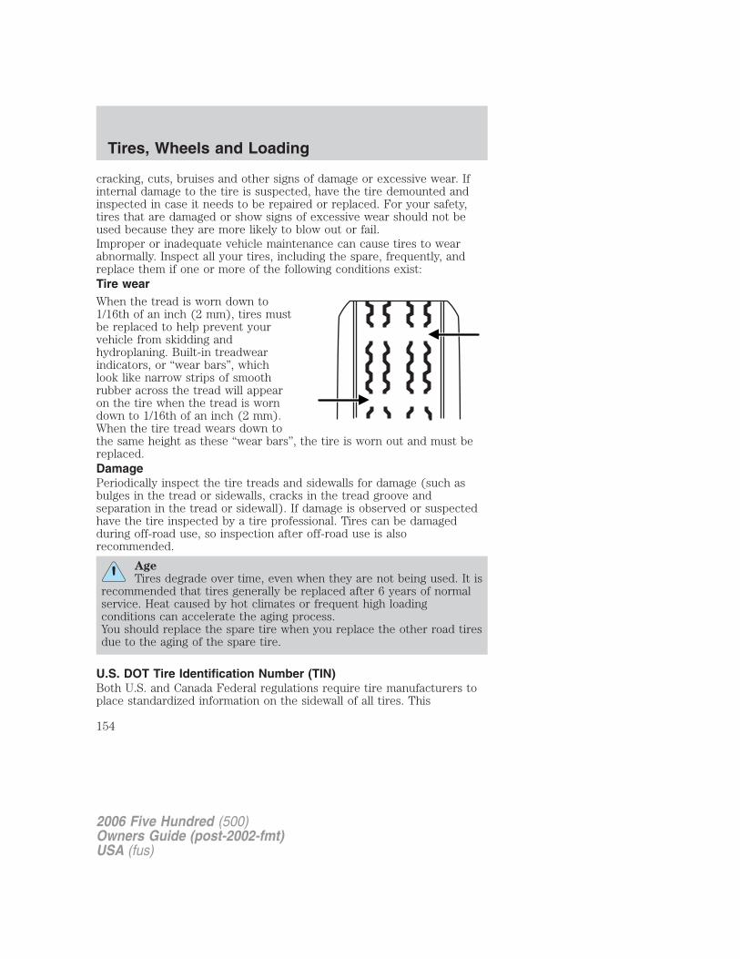
cracking, cuts, bruises and other signs of damage or excessive wear. Ifinternal damage to the tire is suspected, have the tire demounted andinspected in case it needs to be repaired or replaced. For your safety,tires that are damaged or show signs of excessive wear should not beused because they are more likely to blow out or fail.Improper or inadequate vehicle maintenance can cause tires to wearabnormally. Inspect all your tires, including the spare, frequently, andreplace them if one or more of the following conditions exist:Tire wearWhen the tread is worn down to1/16th of an inch (2 mm), tires mustbe replaced to help prevent yourvehicle from skidding andhydroplaning. Built-in treadwearindicators, or “wear bars”, whichlook like narrow strips of smoothrubber across the tread will appearon the tire when the tread is worndown to 1/16th of an inch (2 mm).When the tire tread wears down tothe same height as these “wear bars”, the tire is worn out and must bereplaced.DamagePeriodically inspect the tire treads and sidewalls for damage (such asbulges in the tread or sidewalls, cracks in the tread groove andseparation in the tread or sidewall). If damage is observed or suspectedhave the tire inspected by a tire professional. Tires can be damagedduring off-road use, so inspection after off-road use is alsorecommended.
AgeTires degrade over time, even when they are not being used. It is
recommended that tires generally be replaced after 6 years of normalservice. Heat caused by hot climates or frequent high loadingconditions can accelerate the aging process.You should replace the spare tire when you replace the other road tiresdue to the aging of the spare tire.
U.S. DOT Tire Identification Number (TIN)Both U.S. and Canada Federal regulations require tire manufacturers toplace standardized information on the sidewall of all tires. This
2006 Five Hundred (500)Owners Guide (post-2002-fmt)USA (fus)
Tires, Wheels and Loading
154
information identifies and describes the fundamental characteristics ofthe tire and also provides a U.S. DOT Tire Identification Number forsafety standard certification and in case of a recall.
This begins with the letters “DOT” and indicates that the tire meets allfederal standards. The next two numbers or letters are the plant codedesignating where it was manufactured, the next two are the tire sizecode and the last four numbers represent the week and year the tire wasbuilt. For example, the numbers 317 mean the 31st week of 1997. After2000 the numbers go to four digits. For example, 2501 means the 25thweek of 2001. The numbers in between are identification codes used fortraceability. This information is used to contact customers if a tire defectrequires a recall.
Tire Replacement RequirementsYour vehicle is equipped with tires designed to provide a safe ride andhandling capability.
Only use replacement tires and wheels that are the same sizeand type (such as P-metric versus LT-metric or all-season versus
all-terrain) as those originally provided by Ford. Use of any tire orwheel not recommended by Ford can affect the safety andperformance of your vehicle, which could result in an increased risk ofloss of vehicle control, vehicle rollover, personal injury and death.Additionally the use of non-recommended tires and wheels could causesteering, suspension, axle or transfer case/power transfer unit failure. Ifyou have questions regarding tire replacement, see an authorizeddealer.
Important: Remember to replace the wheel valve stems when the roadtires are replaced on your vehicle.
It is recommended that the two front tires or two rear tires generally bereplaced as a pair.
Safety practicesDriving habits have a great deal to do with your tire mileage and safety.
• Observe posted speed limits
• Avoid fast starts, stops and turns
• Avoid potholes and objects on the road
• Do not run over curbs or hit the tire against a curb when parking
2006 Five Hundred (500)Owners Guide (post-2002-fmt)USA (fus)
Tires, Wheels and Loading
155
If your vehicle is stuck in snow, mud, sand, etc., do not rapidlyspin the tires; spinning the tires can tear the tire and cause an
explosion. A tire can explode in as little as three to five seconds.
Do not spin the wheels at over 35 mph (56 km/h). The tires mayfail and injure a passenger or bystander.
Highway hazardsNo matter how carefully you drive there’s always the possibility that youmay eventually have a flat tire on the highway. Drive slowly to theclosest safe area out of traffic. This may further damage the flat tire, butyour safety is more important.If you feel a sudden vibration or ride disturbance while driving, or yoususpect your tire or vehicle has been damaged, immediately reduce yourspeed. Drive with caution until you can safely pull off the road. Stop andinspect the tires for damage. If a tire is under-inflated or damaged,deflate it, remove wheel and replace it with your spare tire and wheel. Ifyou cannot detect a cause, have the vehicle towed to the nearest repairfacility or tire dealer to have the vehicle inspected.
Tire and wheel alignmentA bad jolt from hitting a curb or pothole can cause the front end of yourvehicle to become misaligned or cause damage to your tires. If yourvehicle seems to pull to one side when you’re driving, the wheels may beout of alignment. Have an authorized dealer check the wheel alignmentperiodically.
Wheel misalignment in the front or the rear can cause uneven and rapidtreadwear of your tires and should be corrected by an authorized dealer.Front wheel drive (FWD) vehicles and those with an independent rearsuspension (if equipped) may require alignment of all four wheels.
The tires should also be balanced periodically. An unbalanced tire andwheel assembly may result in irregular tire wear.
Tire rotationRotating your tires at the recommended interval (as indicated in thescheduled maintenance information that comes with your vehicle) willhelp your tires wear more evenly, providing better tire performance andlonger tire life. Unless otherwise specified, rotate the tires approximatelyevery 5,000 miles (8,000 km).
2006 Five Hundred (500)Owners Guide (post-2002-fmt)USA (fus)
Tires, Wheels and Loading
156
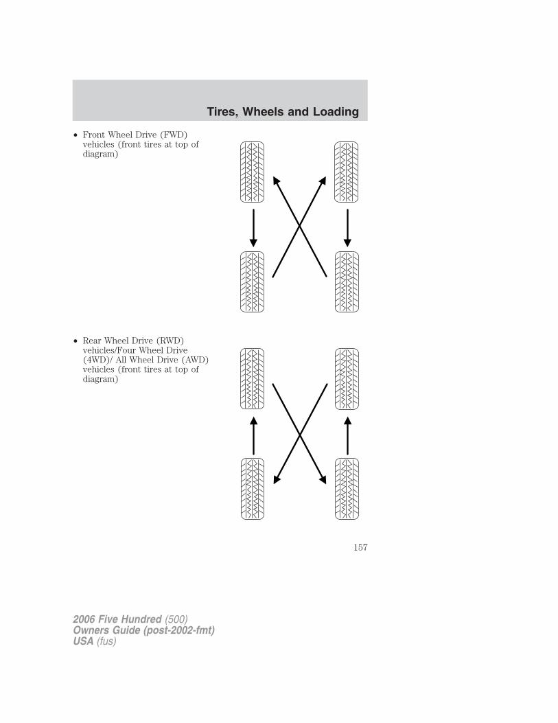
• Front Wheel Drive (FWD)vehicles (front tires at top ofdiagram)
• Rear Wheel Drive (RWD)vehicles/Four Wheel Drive(4WD)/ All Wheel Drive (AWD)vehicles (front tires at top ofdiagram)
2006 Five Hundred (500)Owners Guide (post-2002-fmt)USA (fus)
Tires, Wheels and Loading
157
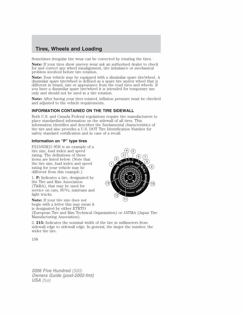
Sometimes irregular tire wear can be corrected by rotating the tires.Note: If your tires show uneven wear ask an authorized dealer to checkfor and correct any wheel misalignment, tire imbalance or mechanicalproblem involved before tire rotation.Note: Your vehicle may be equipped with a dissimilar spare tire/wheel. Adissimilar spare tire/wheel is defined as a spare tire and/or wheel that isdifferent in brand, size or appearance from the road tires and wheels. Ifyou have a dissimilar spare tire/wheel it is intended for temporary useonly and should not be used in a tire rotation.
Note: After having your tires rotated, inflation pressure must be checkedand adjusted to the vehicle requirements.
INFORMATION CONTAINED ON THE TIRE SIDEWALLBoth U.S. and Canada Federal regulations require tire manufacturers toplace standardized information on the sidewall of all tires. Thisinformation identifies and describes the fundamental characteristics ofthe tire and also provides a U.S. DOT Tire Identification Number forsafety standard certification and in case of a recall.
Information on “P” type tiresP215/65R15 95H is an example of atire size, load index and speedrating. The definitions of theseitems are listed below. (Note thatthe tire size, load index and speedrating for your vehicle may bedifferent from this example.)
1. P: Indicates a tire, designated bythe Tire and Rim Association(T&RA), that may be used forservice on cars, SUVs, minivans andlight trucks.
Note: If your tire size does notbegin with a letter this may mean itis designated by either ETRTO(European Tire and Rim Technical Organization) or JATMA (Japan TireManufacturing Association).
2. 215: Indicates the nominal width of the tire in millimeters fromsidewall edge to sidewall edge. In general, the larger the number, thewider the tire.
2006 Five Hundred (500)Owners Guide (post-2002-fmt)USA (fus)
Tires, Wheels and Loading
158
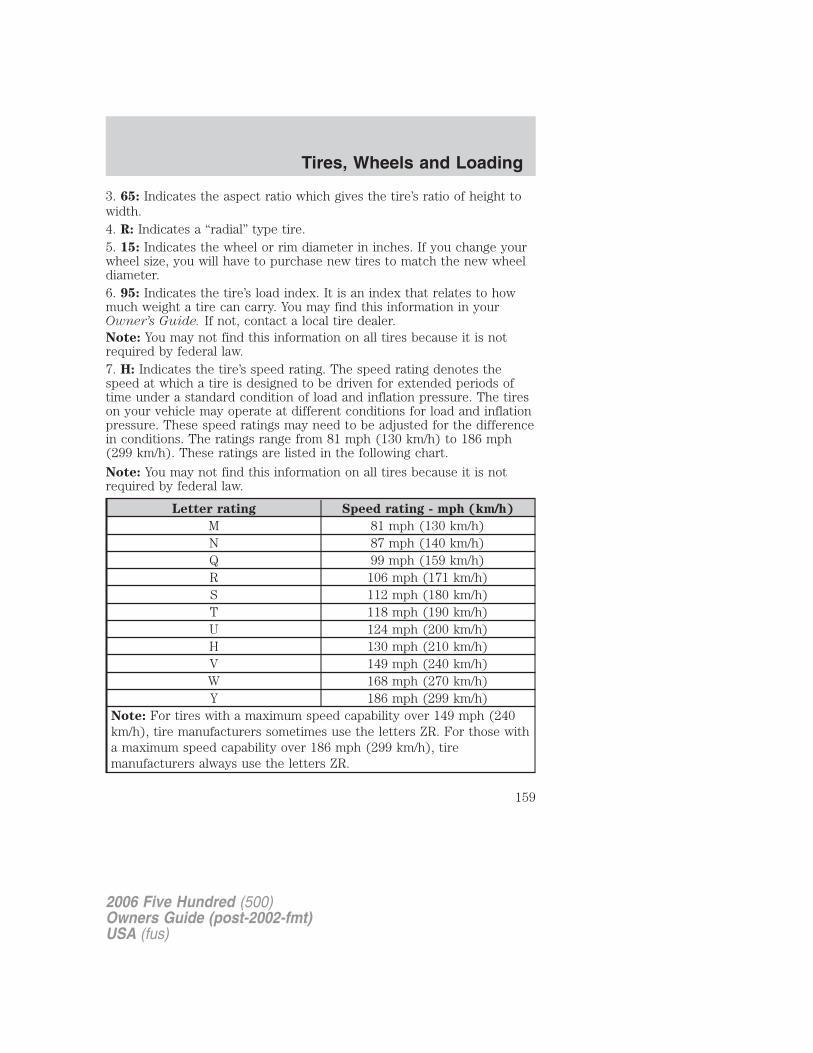
3. 65: Indicates the aspect ratio which gives the tire’s ratio of height towidth.4. R: Indicates a “radial” type tire.5. 15: Indicates the wheel or rim diameter in inches. If you change yourwheel size, you will have to purchase new tires to match the new wheeldiameter.6. 95: Indicates the tire’s load index. It is an index that relates to howmuch weight a tire can carry. You may find this information in yourOwner’s Guide. If not, contact a local tire dealer.Note: You may not find this information on all tires because it is notrequired by federal law.7. H: Indicates the tire’s speed rating. The speed rating denotes thespeed at which a tire is designed to be driven for extended periods oftime under a standard condition of load and inflation pressure. The tireson your vehicle may operate at different conditions for load and inflationpressure. These speed ratings may need to be adjusted for the differencein conditions. The ratings range from 81 mph (130 km/h) to 186 mph(299 km/h). These ratings are listed in the following chart.
Note: You may not find this information on all tires because it is notrequired by federal law.
Letter rating Speed rating - mph (km/h)
M 81 mph (130 km/h)N 87 mph (140 km/h)Q 99 mph (159 km/h)R 106 mph (171 km/h)S 112 mph (180 km/h)T 118 mph (190 km/h)U 124 mph (200 km/h)H 130 mph (210 km/h)V 149 mph (240 km/h)W 168 mph (270 km/h)Y 186 mph (299 km/h)
Note: For tires with a maximum speed capability over 149 mph (240km/h), tire manufacturers sometimes use the letters ZR. For those witha maximum speed capability over 186 mph (299 km/h), tiremanufacturers always use the letters ZR.
2006 Five Hundred (500)Owners Guide (post-2002-fmt)USA (fus)
Tires, Wheels and Loading
159
8. U.S. DOT Tire Identification Number (TIN): This begins with theletters “DOT” and indicates that the tire meets all federal standards. Thenext two numbers or letters are the plant code designating where it wasmanufactured, the next two are the tire size code and the last fournumbers represent the week and year the tire was built. For example,the numbers 317 mean the 31st week of 1997. After 2000 the numbersgo to four digits. For example, 2501 means the 25th week of 2001. Thenumbers in between are identification codes used for traceability. Thisinformation is used to contact customers if a tire defect requires a recall.
9. M+S or M/S: Mud and Snow, orAT: All Terrain, orAS: All Season.
10. Tire Ply Composition and Material Used: Indicates the number ofplies or the number of layers of rubber-coated fabric in the tire tread andsidewall. Tire manufacturers also must indicate the ply materials in thetire and the sidewall, which include steel, nylon, polyester, and others.
11. Maximum Load: Indicates the maximum load in kilograms andpounds that can be carried by the tire. Refer to the Safety ComplianceCertification Label, which is located on the B-Pillar or the edge of thedriver’s door, for the correct tire pressure for your vehicle.
12. Treadwear, Traction and Temperature Grades
• Treadwear: The treadwear grade is a comparative rating based on thewear rate of the tire when tested under controlled conditions on aspecified government test course. For example, a tire graded 150would wear one and one-half (11⁄2) times as well on the governmentcourse as a tire graded 100.
• Traction: The traction grades, from highest to lowest are AA, A, B,and C. The grades represent the tire’s ability to stop on wet pavementas measured under controlled conditions on specified government testsurfaces of asphalt and concrete. A tire marked C may have poortraction performance.
• Temperature: The temperature grades are A (the highest), B and C,representing the tire’s resistance to the generation of heat and itsability to dissipate heat when tested under controlled conditions on aspecified indoor laboratory test wheel.
2006 Five Hundred (500)Owners Guide (post-2002-fmt)USA (fus)
Tires, Wheels and Loading
160
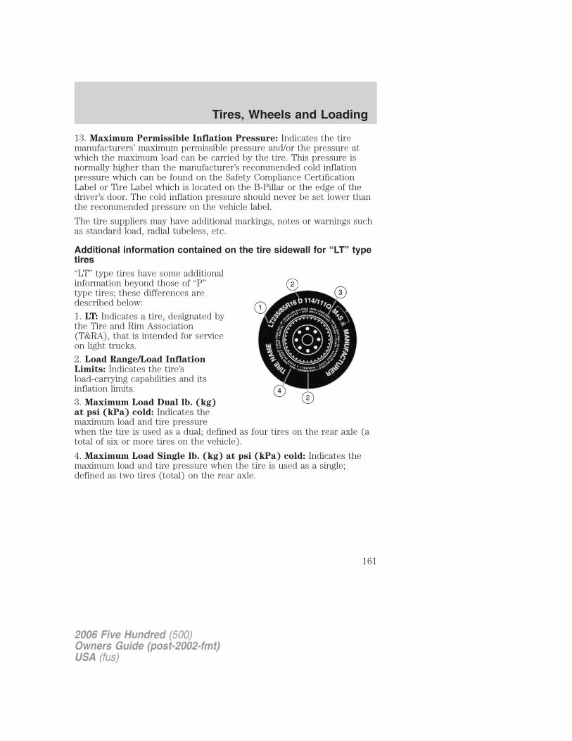
13. Maximum Permissible Inflation Pressure: Indicates the tiremanufacturers’ maximum permissible pressure and/or the pressure atwhich the maximum load can be carried by the tire. This pressure isnormally higher than the manufacturer’s recommended cold inflationpressure which can be found on the Safety Compliance CertificationLabel or Tire Label which is located on the B-Pillar or the edge of thedriver’s door. The cold inflation pressure should never be set lower thanthe recommended pressure on the vehicle label.
The tire suppliers may have additional markings, notes or warnings suchas standard load, radial tubeless, etc.
Additional information contained on the tire sidewall for “LT” typetires“LT” type tires have some additionalinformation beyond those of “P”type tires; these differences aredescribed below:
1. LT: Indicates a tire, designated bythe Tire and Rim Association(T&RA), that is intended for serviceon light trucks.
2. Load Range/Load InflationLimits: Indicates the tire’sload-carrying capabilities and itsinflation limits.
3. Maximum Load Dual lb. (kg)at psi (kPa) cold: Indicates themaximum load and tire pressurewhen the tire is used as a dual; defined as four tires on the rear axle (atotal of six or more tires on the vehicle).
4. Maximum Load Single lb. (kg) at psi (kPa) cold: Indicates themaximum load and tire pressure when the tire is used as a single;defined as two tires (total) on the rear axle.
2006 Five Hundred (500)Owners Guide (post-2002-fmt)USA (fus)
Tires, Wheels and Loading
161
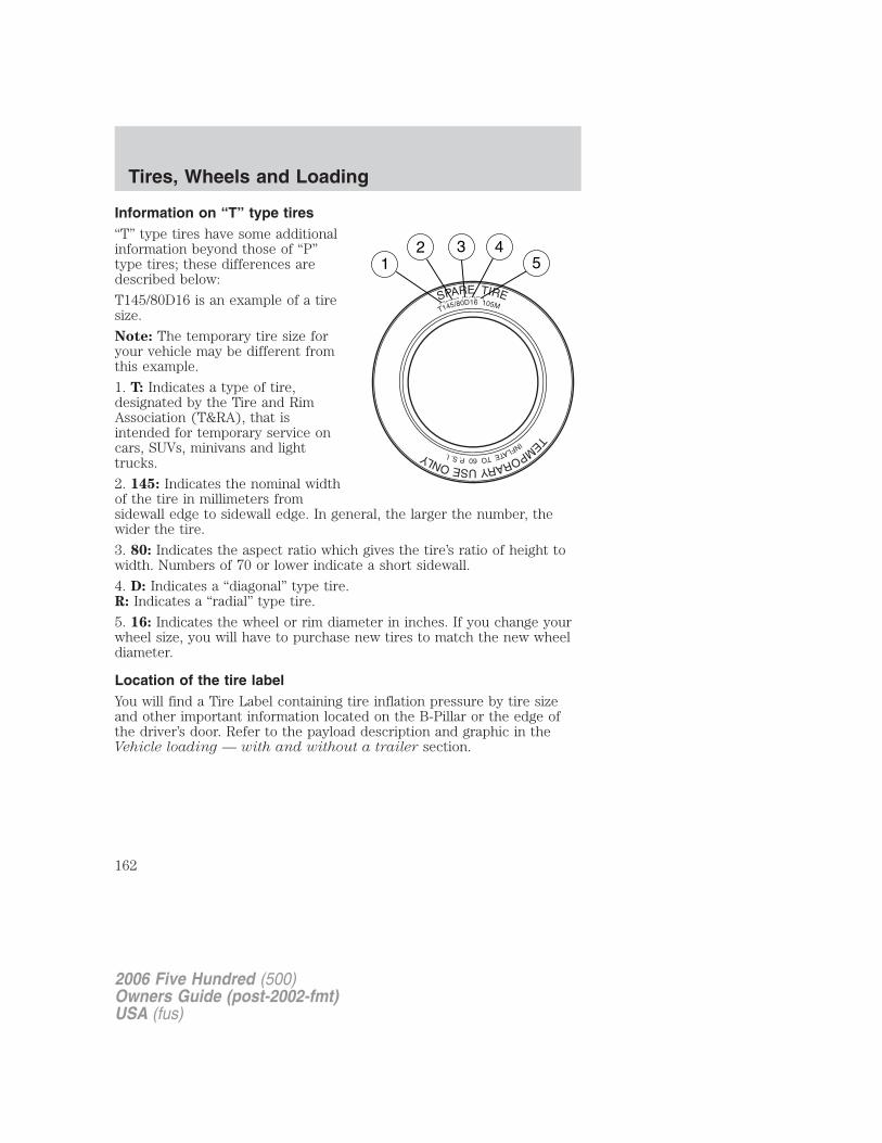
Information on “T” type tires“T” type tires have some additionalinformation beyond those of “P”type tires; these differences aredescribed below:
T145/80D16 is an example of a tiresize.
Note: The temporary tire size foryour vehicle may be different fromthis example.
1. T: Indicates a type of tire,designated by the Tire and RimAssociation (T&RA), that isintended for temporary service oncars, SUVs, minivans and lighttrucks.
2. 145: Indicates the nominal widthof the tire in millimeters fromsidewall edge to sidewall edge. In general, the larger the number, thewider the tire.
3. 80: Indicates the aspect ratio which gives the tire’s ratio of height towidth. Numbers of 70 or lower indicate a short sidewall.
4. D: Indicates a “diagonal” type tire.R: Indicates a “radial” type tire.
5. 16: Indicates the wheel or rim diameter in inches. If you change yourwheel size, you will have to purchase new tires to match the new wheeldiameter.
Location of the tire labelYou will find a Tire Label containing tire inflation pressure by tire sizeand other important information located on the B-Pillar or the edge ofthe driver’s door. Refer to the payload description and graphic in theVehicle loading — with and without a trailer section.
2006 Five Hundred (500)Owners Guide (post-2002-fmt)USA (fus)
Tires, Wheels and Loading
162
SNOW TIRES AND CHAINS
Snow tires must be the same size and grade as the tires youcurrently have on your vehicle.
The tires on your vehicle have all weather treads to provide traction inrain and snow. However, in some climates, you may need to use snowtires and chains.
Follow these guidelines when using snow tires and chains:
• Use only SAE class “S” cables or equivalent on the front axle forP215/60R17 equipped vehicles. SAE class “S” chains or otherconventional link chains may cause damage to the vehicles wheelhouse and/or body. Use of optional spike spider type traction devicesor equivalent is also acceptable.
• Do not install tire chains, cables, or optional traction devices on therear tires. This could cause damage to the vehicle’s wheel house orbody.
• Do not use tire chains, cables, or optional traction devices withoptional P225/55R18 tires.
• Install cable chains securely, verifying that the cables do not touch anywiring, brake lines or fuel lines.
• Drive cautiously. If you hear the cables rub or bang against yourvehicle, stop and re-tighten the cables. If this does not work, removethe cables to prevent damage to your vehicle.
• If possible, avoid fully loading your vehicle.
• Remove the tire cables when they are no longer needed. Do not usetire cables on dry roads.
• The suspension insulation and bumpers will help prevent vehicledamage. Do not remove these components from your vehicle whenusing snow tires and chains.
• Do not exceed 30 mph (48 km/h) with tire cables on your vehicle.
VEHICLE LOADING – WITH AND WITHOUT A TRAILERThis section will guide you in the proper loading of your vehicle and/ortrailer, to keep your loaded vehicle weight within its design ratingcapability, with or without a trailer. Properly loading your vehicle willprovide maximum return of vehicle design performance. Before loadingyour vehicle, familiarize yourself with the following terms for determining
2006 Five Hundred (500)Owners Guide (post-2002-fmt)USA (fus)
Tires, Wheels and Loading
163
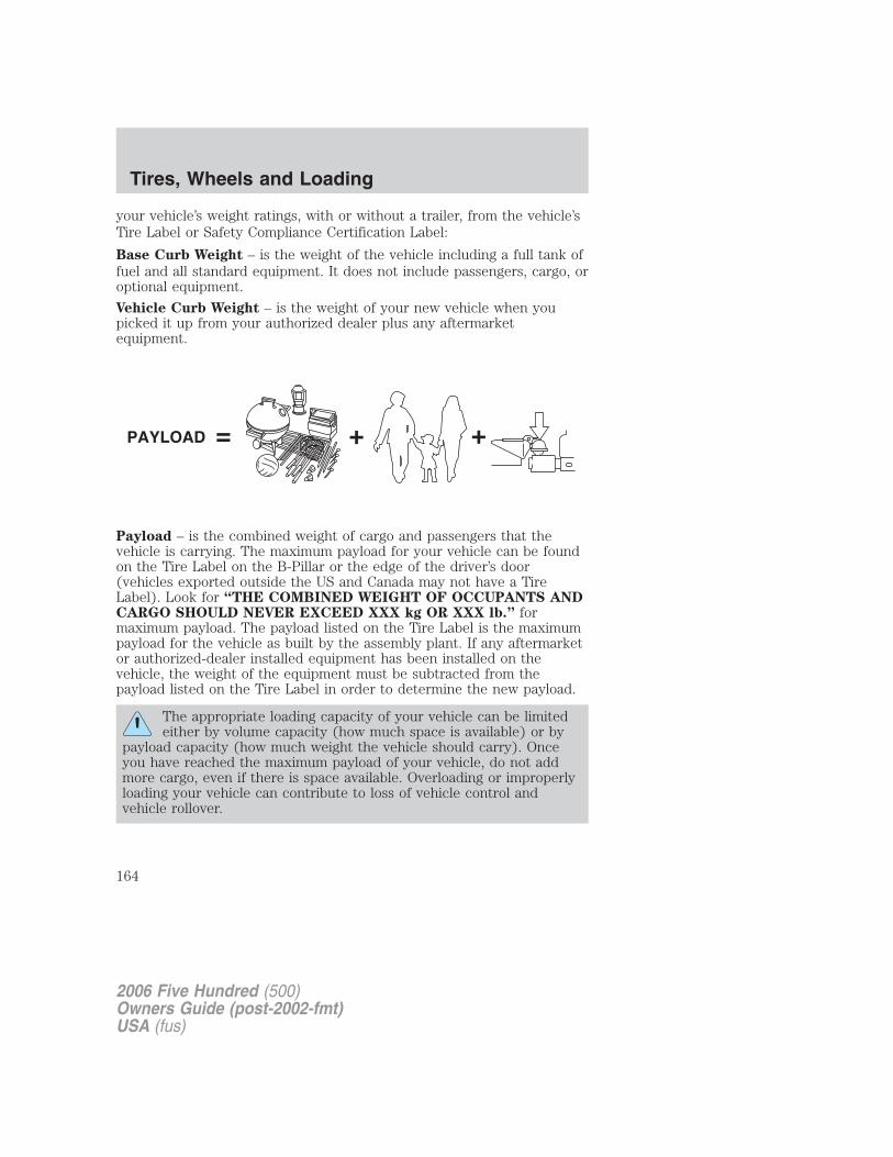
your vehicle’s weight ratings, with or without a trailer, from the vehicle’sTire Label or Safety Compliance Certification Label:
Base Curb Weight – is the weight of the vehicle including a full tank offuel and all standard equipment. It does not include passengers, cargo, oroptional equipment.
Vehicle Curb Weight – is the weight of your new vehicle when youpicked it up from your authorized dealer plus any aftermarketequipment.
Payload – is the combined weight of cargo and passengers that thevehicle is carrying. The maximum payload for your vehicle can be foundon the Tire Label on the B-Pillar or the edge of the driver’s door(vehicles exported outside the US and Canada may not have a TireLabel). Look for “THE COMBINED WEIGHT OF OCCUPANTS ANDCARGO SHOULD NEVER EXCEED XXX kg OR XXX lb.” formaximum payload. The payload listed on the Tire Label is the maximumpayload for the vehicle as built by the assembly plant. If any aftermarketor authorized-dealer installed equipment has been installed on thevehicle, the weight of the equipment must be subtracted from thepayload listed on the Tire Label in order to determine the new payload.
The appropriate loading capacity of your vehicle can be limitedeither by volume capacity (how much space is available) or by
payload capacity (how much weight the vehicle should carry). Onceyou have reached the maximum payload of your vehicle, do not addmore cargo, even if there is space available. Overloading or improperlyloading your vehicle can contribute to loss of vehicle control andvehicle rollover.
2006 Five Hundred (500)Owners Guide (post-2002-fmt)USA (fus)
Tires, Wheels and Loading
164
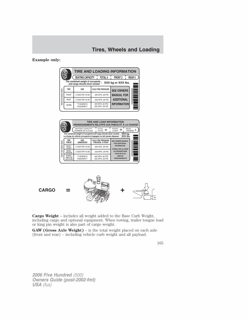
Example only:
Cargo Weight – includes all weight added to the Base Curb Weight,including cargo and optional equipment. When towing, trailer tongue loador king pin weight is also part of cargo weight.
GAW (Gross Axle Weight) – is the total weight placed on each axle(front and rear) – including vehicle curb weight and all payload.
2006 Five Hundred (500)Owners Guide (post-2002-fmt)USA (fus)
Tires, Wheels and Loading
165
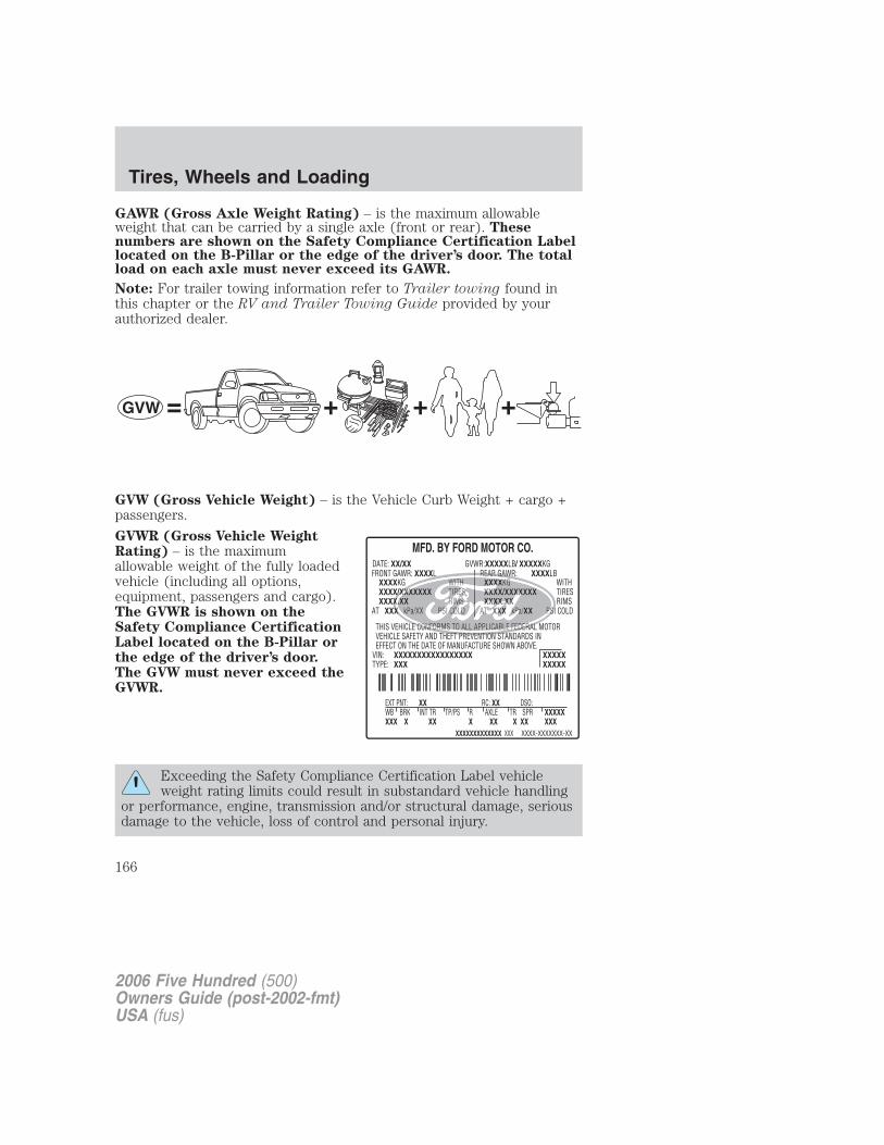
GAWR (Gross Axle Weight Rating) – is the maximum allowableweight that can be carried by a single axle (front or rear). Thesenumbers are shown on the Safety Compliance Certification Labellocated on the B-Pillar or the edge of the driver’s door. The totalload on each axle must never exceed its GAWR.
Note: For trailer towing information refer to Trailer towing found inthis chapter or the RV and Trailer Towing Guide provided by yourauthorized dealer.
GVW (Gross Vehicle Weight) – is the Vehicle Curb Weight + cargo +passengers.
GVWR (Gross Vehicle WeightRating) – is the maximumallowable weight of the fully loadedvehicle (including all options,equipment, passengers and cargo).The GVWR is shown on theSafety Compliance CertificationLabel located on the B-Pillar orthe edge of the driver’s door.The GVW must never exceed theGVWR.
Exceeding the Safety Compliance Certification Label vehicleweight rating limits could result in substandard vehicle handling
or performance, engine, transmission and/or structural damage, seriousdamage to the vehicle, loss of control and personal injury.
2006 Five Hundred (500)Owners Guide (post-2002-fmt)USA (fus)
Tires, Wheels and Loading
166
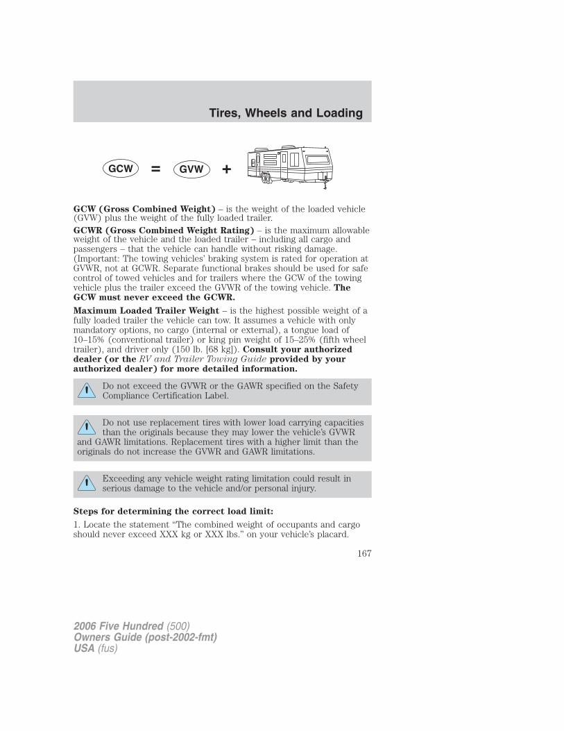
GCW (Gross Combined Weight) – is the weight of the loaded vehicle(GVW) plus the weight of the fully loaded trailer.GCWR (Gross Combined Weight Rating) – is the maximum allowableweight of the vehicle and the loaded trailer – including all cargo andpassengers – that the vehicle can handle without risking damage.(Important: The towing vehicles’ braking system is rated for operation atGVWR, not at GCWR. Separate functional brakes should be used for safecontrol of towed vehicles and for trailers where the GCW of the towingvehicle plus the trailer exceed the GVWR of the towing vehicle. TheGCW must never exceed the GCWR.
Maximum Loaded Trailer Weight – is the highest possible weight of afully loaded trailer the vehicle can tow. It assumes a vehicle with onlymandatory options, no cargo (internal or external), a tongue load of10–15% (conventional trailer) or king pin weight of 15–25% (fifth wheeltrailer), and driver only (150 lb. [68 kg]). Consult your authorizeddealer (or the RV and Trailer Towing Guide provided by yourauthorized dealer) for more detailed information.
Do not exceed the GVWR or the GAWR specified on the SafetyCompliance Certification Label.
Do not use replacement tires with lower load carrying capacitiesthan the originals because they may lower the vehicle’s GVWR
and GAWR limitations. Replacement tires with a higher limit than theoriginals do not increase the GVWR and GAWR limitations.
Exceeding any vehicle weight rating limitation could result inserious damage to the vehicle and/or personal injury.
Steps for determining the correct load limit:
1. Locate the statement “The combined weight of occupants and cargoshould never exceed XXX kg or XXX lbs.” on your vehicle’s placard.
2006 Five Hundred (500)Owners Guide (post-2002-fmt)USA (fus)
Tires, Wheels and Loading
167
2. Determine the combined weight of the driver and passengers that willbe riding in your vehicle.3. Subtract the combined weight of the driver and passengers from XXXkg or XXX lbs.4. The resulting figure equals the available amount of cargo and luggageload capacity. For example, if the “XXX” amount equals 1,400 lbs. andthere will be five 150 lb. passengers in your vehicle, the amount ofavailable cargo and luggage load capacity is 650 lbs. (1400–750 (5 x 150)= 650 lb.). In metric units (635–340 (5 x 68) = 295 kg.)
5. Determine the combined weight of luggage and cargo being loaded onthe vehicle. That weight may not safely exceed the available cargo andluggage load capacity calculated in Step 4.
6. If your vehicle will be towing a trailer, load from your trailer will betransferred to your vehicle. Consult this manual to determine how thisreduces the available cargo and luggage load capacity of your vehicle.
The following gives you a few examples on how to calculate the availableamount of cargo and luggage load capacity:
• Another example for your vehicle with 1400 lb. (635 kg) of cargo andluggage capacity. You decide to go golfing. Is there enough loadcapacity to carry you, 4 of your friends and all the golf bags? You andfour friends average 220 lb. (99 kg) each and the golf bags weighapproximately 30 lb. (13.5 kg) each. The calculation would be: 1400 –(5 x 220) – (5 x 30) = 1400 – 1100 – 150 = 150 lb. Yes, you haveenough load capacity in your vehicle to transport four friends andyour golf bags. In metric units, the calculation would be: 635 kg — (5x 99 kg) — (5 x 13.5 kg) = 635 — 495 — 67.5 = 72.5 kg.
• A final example for your vehicle with 1400 lb. (635 kg) of cargo andluggage capacity. You and one of your friends decide to pick upcement from the local home improvement store to finish that patioyou have been planning for the past 2 years. Measuring the inside ofthe vehicle with the rear seat folded down, you have room for 12-100lb. (45 kg) bags of cement. Do you have enough load capacity totransport the cement to your home? If you and your friend each weigh220 lb. (99 kg), the calculation would be: 1400 – (2 x 220) – (12 x100) = 1400 – 440 – 1200 = – 240 lb. No, you do not have enoughcargo capacity to carry that much weight. In metric units, thecalculation would be: 635 kg — (2 x 99 kg) — (12 x 45 kg) = 635 —198 — 540 = —103 kg. You will need to reduce the load weight by atleast 240 lb. (104 kg). If you remove 3-100 lb. (45 kg) cement bags,then the load calculation would be:
2006 Five Hundred (500)Owners Guide (post-2002-fmt)USA (fus)
Tires, Wheels and Loading
168
1400 – (2 x 220) – (9 x 100) = 1400 – 440 – 900 = 60 lb. Now youhave the load capacity to transport the cement and your friend home.In metric units, the calculation would be: 635 kg — (2 x 99 kg) — (9x 45 kg) = 635 — 198 — 405 = 32 kg.
The above calculations also assume that the loads are positioned in yourvehicle in a manner that does not overload the Front or the Rear GrossAxle Weight Rating specified for your vehicle on the Safety ComplianceCertification Label found on the edge of the driver’s door.
TRAILER TOWINGYour vehicle is capable of towing a trailer up to 1,000 lb. (454 kg) grosstrailer weight with a maximum tongue load of 100 lb. (45 kg). Do nottow a trailer until your vehicle has been driven at least 500 miles (800km).Towing a trailer places an additional load on your vehicle’s engine,transmission, brakes, tires and suspension. Inspect these componentscarefully after towing.
Do not exceed the GVWR or the GAWR specified on thecertification label.
Towing trailers beyond the maximum recommended gross trailerweight exceeds the limit of the vehicle and could result in
engine damage, transmission damage, structural damage, loss of vehiclecontrol, vehicle rollover and personal injury.
Preparing to towUse the proper equipment for towing a trailer and make sure it isproperly attached to your vehicle. See your authorized dealer or areliable trailer dealer if you require assistance.
HitchesDo not use hitches that clamp onto the vehicle bumper. Use a loadcarrying hitch. You must distribute the load in your trailer so that10–15% of the total weight of the trailer is on the tongue.
Safety chainsAlways connect the trailer’s safety chains to the frame or hook retainersof the vehicle hitch. To connect the trailer’s safety chains, cross thechains under the trailer tongue and allow slack for turning corners.
2006 Five Hundred (500)Owners Guide (post-2002-fmt)USA (fus)
Tires, Wheels and Loading
169
If you use a rental trailer, follow the instructions that the rental agencygives to you.Do not attach safety chains to the bumper.
Trailer brakesElectric brakes and manual, automatic or surge-type trailer brakes aresafe if installed properly and adjusted to the manufacturer’sspecifications. The trailer brakes must meet local and Federalregulations.
Do not connect a trailer’s hydraulic brake system directly to yourvehicle’s brake system. Your vehicle may not have enough
braking power and your chances of having a collision greatly increase.
The braking system of the tow vehicle is rated for operation at theGVWR not GCWR.
Trailer lampsTrailer lamps are required on most towed vehicles. Make sure all runninglights, brake lights, turn signals and hazard lights are working. See yourauthorized dealer or trailer rental agency for proper instructions andequipment for hooking up trailer lamps.
Driving while you towWhen towing a trailer:• Turn off the speed control. The speed control may shut off
automatically when you are towing on long, steep grades.• Consult your local motor vehicle speed regulations for towing a trailer.• It is recommended to select the L (Low) gear position when additional
engine braking is needed. In situations such as prolonged downhilldriving on steep grades (i.e., driving in mountainous areas), additionalengine braking is needed to reduce the load on the vehicle’s regularbrake system to prevent them from overheating.
• Anticipate stops and brake gradually.
Servicing after towingIf you tow a trailer for long distances, your vehicle will require morefrequent service intervals. Refer to your scheduled maintenanceinformation for more information.
Trailer towing tips• Practice turning, stopping and backing up before starting on a trip to
get the feel of the vehicle trailer combination. When turning, makewider turns so the trailer wheels will clear curbs and other obstacles.
2006 Five Hundred (500)Owners Guide (post-2002-fmt)USA (fus)
Tires, Wheels and Loading
170
• Allow more distance for stopping with a trailer attached.
• If you are driving down a long or steep hill, shift into the “L” gearposition. Do not apply the brakes continuously, as they may overheatand become less effective.
• The trailer tongue weight should be 10–15% of the loaded trailerweight.
• After you have traveled 50 miles (80 km), thoroughly check yourhitch, electrical connections and trailer wheel lug nuts.
• To aid in engine/transmission cooling and A/C efficiency during hotweather while stopped in traffic, place the gearshift lever in P (Park).
• Vehicles with trailers should not be parked on a grade. If you mustpark on a grade, place wheel chocks under the trailer’s wheels.
RECREATIONAL TOWINGFollow these guidelines for your specific powertrain combination to towyour vehicle for personal travel (such as behind a recreational vehicle ormoving truck).
In case of roadside emergency with a disabled vehicle, please refer to theWrecker towing section in the Driving chapter.
These guidelines are designed to ensure that your transmission is notdamaged due to insufficient lubrication.
Front Wheel Drive (FWD) vehicles:
Do not tow your Front Wheel Drive vehicle with the front drive wheelson the ground as transaxle damage may occur. It is recommended to towyour vehicle with the front drive wheels on a dolly or use a car-haulingtrailer.
All Wheel Drive (AWD) vehicles:
Do not tow your All Wheel Drive vehicle with any wheels on the groundas vehicle or transaxle damage may occur. It is recommended to towyour vehicle using a car-hauling trailer.
2006 Five Hundred (500)Owners Guide (post-2002-fmt)USA (fus)
Tires, Wheels and Loading
171
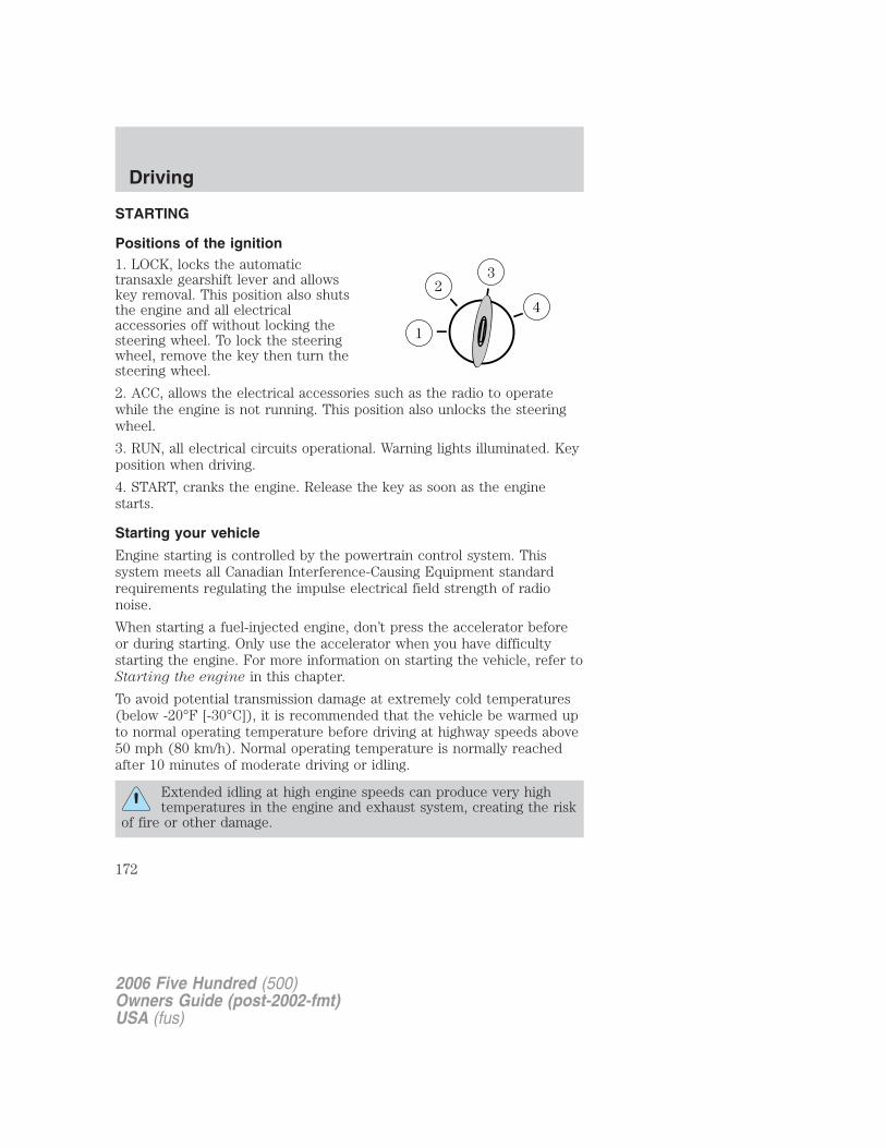
STARTING
Positions of the ignition1. LOCK, locks the automatictransaxle gearshift lever and allowskey removal. This position also shutsthe engine and all electricalaccessories off without locking thesteering wheel. To lock the steeringwheel, remove the key then turn thesteering wheel.
2. ACC, allows the electrical accessories such as the radio to operatewhile the engine is not running. This position also unlocks the steeringwheel.
3. RUN, all electrical circuits operational. Warning lights illuminated. Keyposition when driving.
4. START, cranks the engine. Release the key as soon as the enginestarts.
Starting your vehicle
Engine starting is controlled by the powertrain control system. Thissystem meets all Canadian Interference-Causing Equipment standardrequirements regulating the impulse electrical field strength of radionoise.
When starting a fuel-injected engine, don’t press the accelerator beforeor during starting. Only use the accelerator when you have difficultystarting the engine. For more information on starting the vehicle, refer toStarting the engine in this chapter.
To avoid potential transmission damage at extremely cold temperatures(below -20°F [-30°C]), it is recommended that the vehicle be warmed upto normal operating temperature before driving at highway speeds above50 mph (80 km/h). Normal operating temperature is normally reachedafter 10 minutes of moderate driving or idling.
Extended idling at high engine speeds can produce very hightemperatures in the engine and exhaust system, creating the risk
of fire or other damage.
2006 Five Hundred (500)Owners Guide (post-2002-fmt)USA (fus)
Driving
172
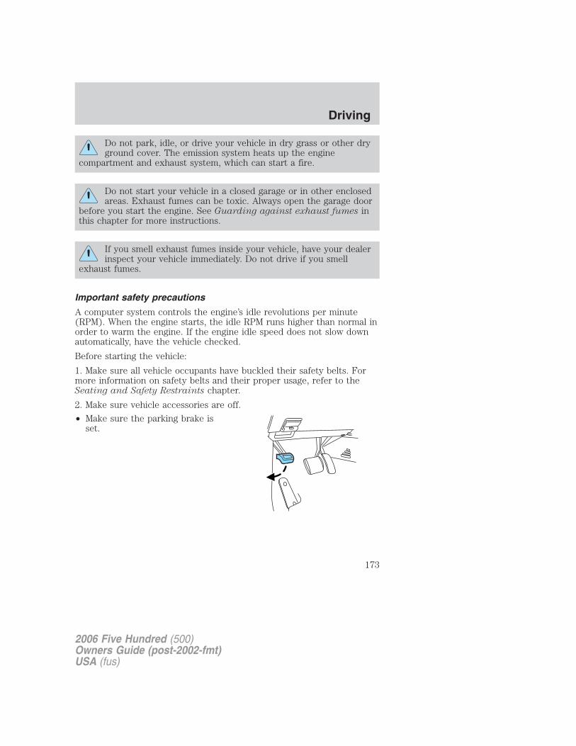
Do not park, idle, or drive your vehicle in dry grass or other dryground cover. The emission system heats up the engine
compartment and exhaust system, which can start a fire.
Do not start your vehicle in a closed garage or in other enclosedareas. Exhaust fumes can be toxic. Always open the garage door
before you start the engine. See Guarding against exhaust fumes inthis chapter for more instructions.
If you smell exhaust fumes inside your vehicle, have your dealerinspect your vehicle immediately. Do not drive if you smell
exhaust fumes.
Important safety precautions
A computer system controls the engine’s idle revolutions per minute(RPM). When the engine starts, the idle RPM runs higher than normal inorder to warm the engine. If the engine idle speed does not slow downautomatically, have the vehicle checked.
Before starting the vehicle:
1. Make sure all vehicle occupants have buckled their safety belts. Formore information on safety belts and their proper usage, refer to theSeating and Safety Restraints chapter.
2. Make sure vehicle accessories are off.
• Make sure the parking brake isset.
2006 Five Hundred (500)Owners Guide (post-2002-fmt)USA (fus)
Driving
173
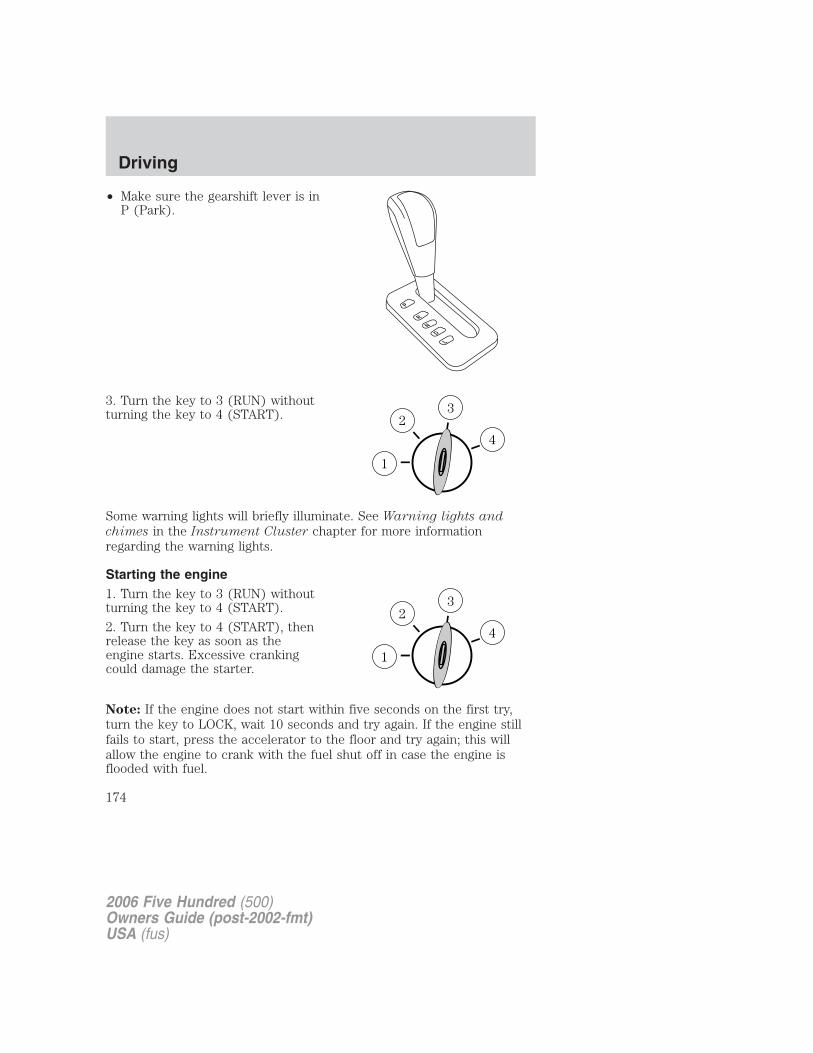
• Make sure the gearshift lever is inP (Park).
3. Turn the key to 3 (RUN) withoutturning the key to 4 (START).
Some warning lights will briefly illuminate. See Warning lights and
chimes in the Instrument Cluster chapter for more informationregarding the warning lights.
Starting the engine1. Turn the key to 3 (RUN) withoutturning the key to 4 (START).
2. Turn the key to 4 (START), thenrelease the key as soon as theengine starts. Excessive crankingcould damage the starter.
Note: If the engine does not start within five seconds on the first try,turn the key to LOCK, wait 10 seconds and try again. If the engine stillfails to start, press the accelerator to the floor and try again; this willallow the engine to crank with the fuel shut off in case the engine isflooded with fuel.
2006 Five Hundred (500)Owners Guide (post-2002-fmt)USA (fus)
Driving
174
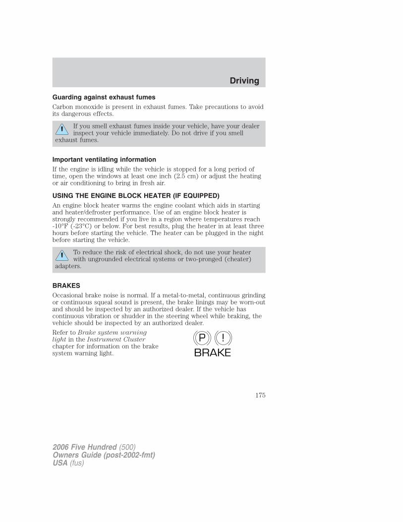
Guarding against exhaust fumesCarbon monoxide is present in exhaust fumes. Take precautions to avoidits dangerous effects.
If you smell exhaust fumes inside your vehicle, have your dealerinspect your vehicle immediately. Do not drive if you smell
exhaust fumes.
Important ventilating informationIf the engine is idling while the vehicle is stopped for a long period oftime, open the windows at least one inch (2.5 cm) or adjust the heatingor air conditioning to bring in fresh air.
USING THE ENGINE BLOCK HEATER (IF EQUIPPED)An engine block heater warms the engine coolant which aids in startingand heater/defroster performance. Use of an engine block heater isstrongly recommended if you live in a region where temperatures reach-10°F (-23°C) or below. For best results, plug the heater in at least threehours before starting the vehicle. The heater can be plugged in the nightbefore starting the vehicle.
To reduce the risk of electrical shock, do not use your heaterwith ungrounded electrical systems or two-pronged (cheater)
adapters.
BRAKESOccasional brake noise is normal. If a metal-to-metal, continuous grindingor continuous squeal sound is present, the brake linings may be worn-outand should be inspected by an authorized dealer. If the vehicle hascontinuous vibration or shudder in the steering wheel while braking, thevehicle should be inspected by an authorized dealer.
Refer to Brake system warninglight in the Instrument Clusterchapter for information on the brakesystem warning light.
P !BRAKE
2006 Five Hundred (500)Owners Guide (post-2002-fmt)USA (fus)
Driving
175
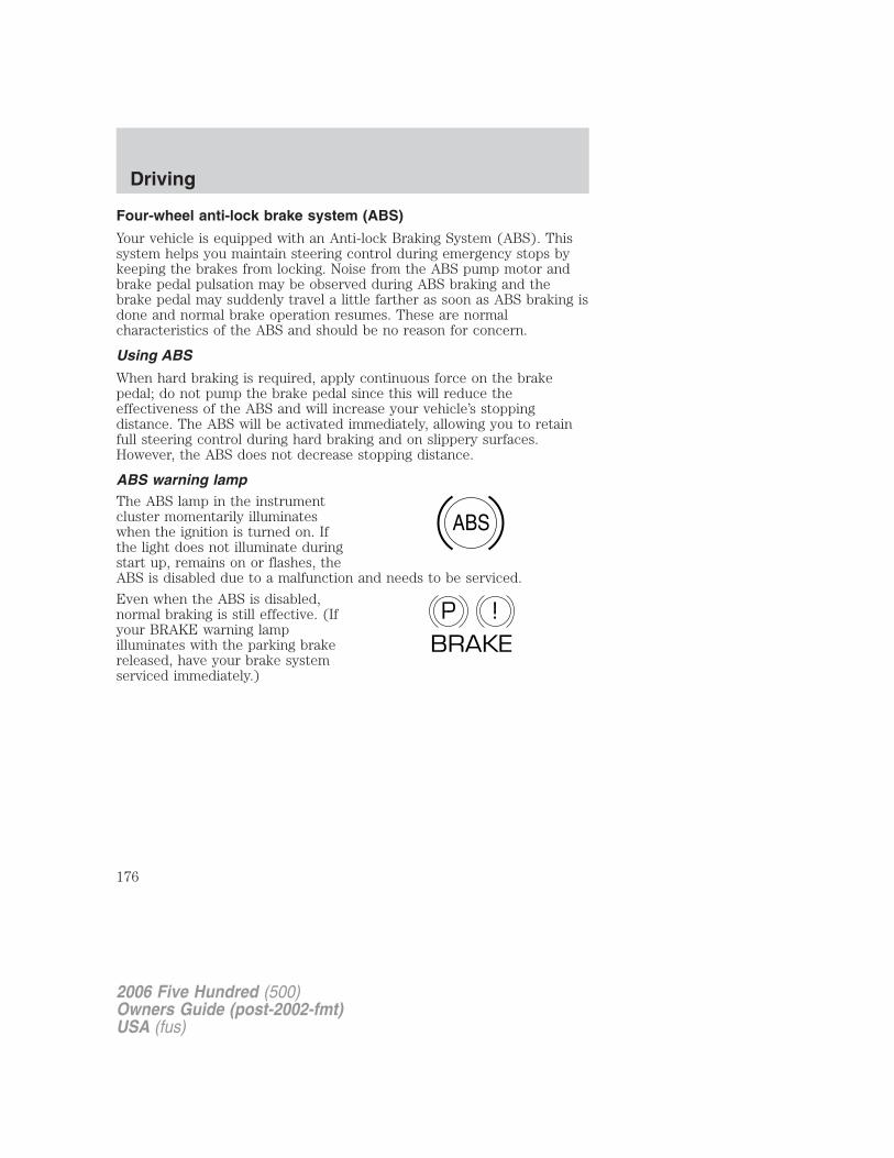
Four-wheel anti-lock brake system (ABS)
Your vehicle is equipped with an Anti-lock Braking System (ABS). Thissystem helps you maintain steering control during emergency stops bykeeping the brakes from locking. Noise from the ABS pump motor andbrake pedal pulsation may be observed during ABS braking and thebrake pedal may suddenly travel a little farther as soon as ABS braking isdone and normal brake operation resumes. These are normalcharacteristics of the ABS and should be no reason for concern.
Using ABS
When hard braking is required, apply continuous force on the brakepedal; do not pump the brake pedal since this will reduce theeffectiveness of the ABS and will increase your vehicle’s stoppingdistance. The ABS will be activated immediately, allowing you to retainfull steering control during hard braking and on slippery surfaces.However, the ABS does not decrease stopping distance.
ABS warning lampThe ABS lamp in the instrumentcluster momentarily illuminateswhen the ignition is turned on. Ifthe light does not illuminate duringstart up, remains on or flashes, theABS is disabled due to a malfunction and needs to be serviced.
Even when the ABS is disabled,normal braking is still effective. (Ifyour BRAKE warning lampilluminates with the parking brakereleased, have your brake systemserviced immediately.)
ABS
P !BRAKE
2006 Five Hundred (500)Owners Guide (post-2002-fmt)USA (fus)
Driving
176
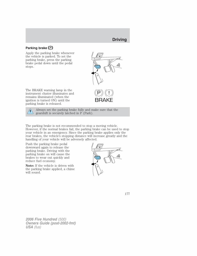
Parking brake
Apply the parking brake wheneverthe vehicle is parked. To set theparking brake, press the parkingbrake pedal down until the pedalstops.
The BRAKE warning lamp in theinstrument cluster illuminates andremains illuminated (when theignition is turned ON) until theparking brake is released.
Always set the parking brake fully and make sure that thegearshift is securely latched in P (Park).
The parking brake is not recommended to stop a moving vehicle.However, if the normal brakes fail, the parking brake can be used to stopyour vehicle in an emergency. Since the parking brake applies only therear brakes, the vehicle’s stopping distance will increase greatly and thehandling of your vehicle will be adversely affected.
Push the parking brake pedaldownward again to release theparking brake. Driving with theparking brake on will cause thebrakes to wear out quickly andreduce fuel economy.
Note: If the vehicle is driven withthe parking brake applied, a chimewill sound.
P !BRAKE
2006 Five Hundred (500)Owners Guide (post-2002-fmt)USA (fus)
Driving
177
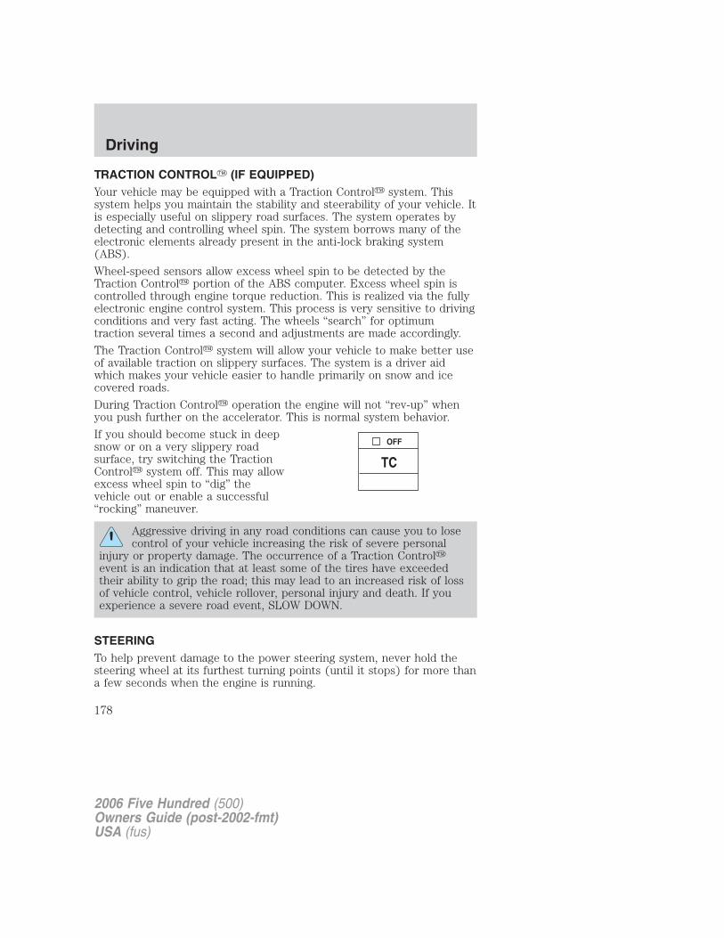
TRACTION CONTROL� (IF EQUIPPED)Your vehicle may be equipped with a Traction Control� system. Thissystem helps you maintain the stability and steerability of your vehicle. Itis especially useful on slippery road surfaces. The system operates bydetecting and controlling wheel spin. The system borrows many of theelectronic elements already present in the anti-lock braking system(ABS).
Wheel-speed sensors allow excess wheel spin to be detected by theTraction Control� portion of the ABS computer. Excess wheel spin iscontrolled through engine torque reduction. This is realized via the fullyelectronic engine control system. This process is very sensitive to drivingconditions and very fast acting. The wheels “search” for optimumtraction several times a second and adjustments are made accordingly.
The Traction Control� system will allow your vehicle to make better useof available traction on slippery surfaces. The system is a driver aidwhich makes your vehicle easier to handle primarily on snow and icecovered roads.
During Traction Control� operation the engine will not “rev-up” whenyou push further on the accelerator. This is normal system behavior.
If you should become stuck in deepsnow or on a very slippery roadsurface, try switching the TractionControl� system off. This may allowexcess wheel spin to “dig” thevehicle out or enable a successful“rocking” maneuver.
Aggressive driving in any road conditions can cause you to losecontrol of your vehicle increasing the risk of severe personal
injury or property damage. The occurrence of a Traction Control�event is an indication that at least some of the tires have exceededtheir ability to grip the road; this may lead to an increased risk of lossof vehicle control, vehicle rollover, personal injury and death. If youexperience a severe road event, SLOW DOWN.
STEERINGTo help prevent damage to the power steering system, never hold thesteering wheel at its furthest turning points (until it stops) for more thana few seconds when the engine is running.
2006 Five Hundred (500)Owners Guide (post-2002-fmt)USA (fus)
Driving
178
It is also important to maintain a proper power steering fluid level in thepower steering fluid reservoir:
• Do not operate the vehicle with a low power steering pump fluid level.See Checking and adding power steering fluid in the Maintenance
and Specifications chapter.
• Some noise is normal during operation. If the noise is excessive, checkfor low power steering pump fluid level before seeking service by yourauthorized dealer.
• Heavy or uneven steering efforts may be caused by low power steeringpump fluid level. Check for low power steering pump fluid level beforeseeking service by your authorized dealer.
• Do not fill the power steering pump reservoir above the maximumlevel, as this may result in leaks from the reservoir. See Checking and
adding power steering fluid in the Maintenance and Specifications
chapter.
If the power steering system breaks down (or if the engine is turnedoff), you can steer the vehicle manually, but it takes more effort.
If the steering wanders or pulls, check for:
• an improperly inflated tire
• uneven tire wear
• loose or worn suspension components
• loose or worn steering components
• improper steering alignment
AUTOMATIC TRANSAXLE OPERATION
Brake-shift interlock
This vehicle is equipped with a brake-shift interlock feature that preventsthe gearshift lever from being moved from P (Park) when the ignition isin the ON position unless the brake pedal is depressed.
If you cannot move the gearshift lever out of P (Park) with ignition inthe ON position and the brake pedal depressed:
1. Remove the trim ring around the gearshift lever.
2006 Five Hundred (500)Owners Guide (post-2002-fmt)USA (fus)
Driving
179
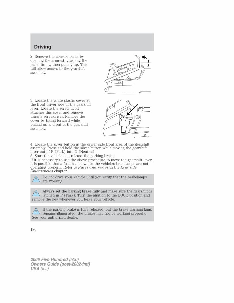
2. Remove the console panel byopening the armrest, grasping thepanel firmly, then pulling up. Thiswill allow access to the gearshiftassembly.
3. Locate the white plastic cover atthe front driver side of the gearshiftlever. Locate the screw whichattaches this cover and removeusing a screwdriver. Remove thecover by tilting forward whilepulling up and out of the gearshiftassembly.
4. Locate the silver button in the driver side front area of the gearshiftassembly. Press and hold the silver button while moving the gearshiftlever out of P (Park) into N (Neutral).5. Start the vehicle and release the parking brake.If it is necessary to use the above procedure to move the gearshift lever,it is possible that a fuse has blown or the vehicle’s brakelamps are notoperating properly. Refer to Fuses and relays in the RoadsideEmergencies chapter.
Do not drive your vehicle until you verify that the brakelampsare working.
Always set the parking brake fully and make sure the gearshift islatched in P (Park). Turn the ignition to the LOCK position and
remove the key whenever you leave your vehicle.
If the parking brake is fully released, but the brake warning lampremains illuminated, the brakes may not be working properly.
See your authorized dealer.
2006 Five Hundred (500)Owners Guide (post-2002-fmt)USA (fus)
Driving
180
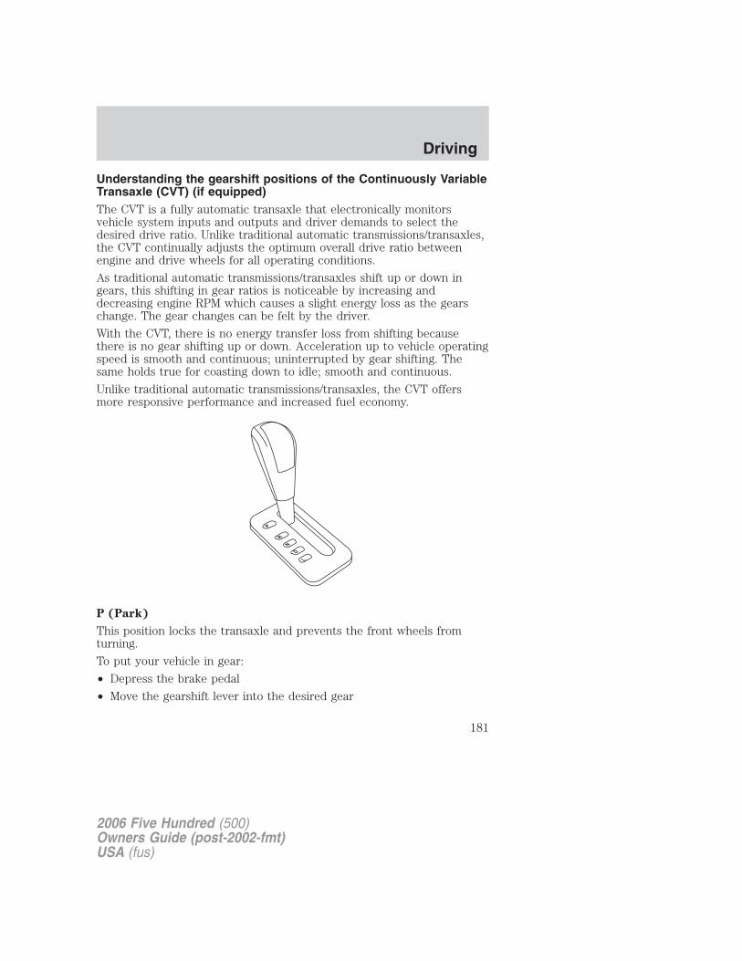
Understanding the gearshift positions of the Continuously VariableTransaxle (CVT) (if equipped)The CVT is a fully automatic transaxle that electronically monitorsvehicle system inputs and outputs and driver demands to select thedesired drive ratio. Unlike traditional automatic transmissions/transaxles,the CVT continually adjusts the optimum overall drive ratio betweenengine and drive wheels for all operating conditions.
As traditional automatic transmissions/transaxles shift up or down ingears, this shifting in gear ratios is noticeable by increasing anddecreasing engine RPM which causes a slight energy loss as the gearschange. The gear changes can be felt by the driver.
With the CVT, there is no energy transfer loss from shifting becausethere is no gear shifting up or down. Acceleration up to vehicle operatingspeed is smooth and continuous; uninterrupted by gear shifting. Thesame holds true for coasting down to idle; smooth and continuous.
Unlike traditional automatic transmissions/transaxles, the CVT offersmore responsive performance and increased fuel economy.
P (Park)
This position locks the transaxle and prevents the front wheels fromturning.
To put your vehicle in gear:
• Depress the brake pedal
• Move the gearshift lever into the desired gear
2006 Five Hundred (500)Owners Guide (post-2002-fmt)USA (fus)
Driving
181
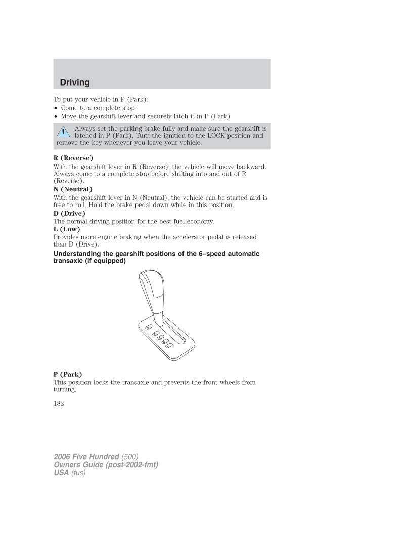
To put your vehicle in P (Park):• Come to a complete stop• Move the gearshift lever and securely latch it in P (Park)
Always set the parking brake fully and make sure the gearshift islatched in P (Park). Turn the ignition to the LOCK position and
remove the key whenever you leave your vehicle.
R (Reverse)
With the gearshift lever in R (Reverse), the vehicle will move backward.Always come to a complete stop before shifting into and out of R(Reverse).N (Neutral)
With the gearshift lever in N (Neutral), the vehicle can be started and isfree to roll. Hold the brake pedal down while in this position.D (Drive)
The normal driving position for the best fuel economy.L (Low)
Provides more engine braking when the accelerator pedal is releasedthan D (Drive).
Understanding the gearshift positions of the 6–speed automatictransaxle (if equipped)
P (Park)
This position locks the transaxle and prevents the front wheels fromturning.
2006 Five Hundred (500)Owners Guide (post-2002-fmt)USA (fus)
Driving
182
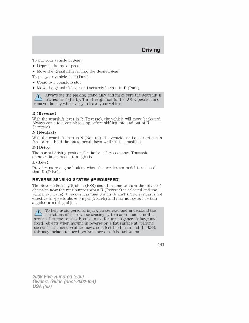
To put your vehicle in gear:• Depress the brake pedal• Move the gearshift lever into the desired gearTo put your vehicle in P (Park):• Come to a complete stop• Move the gearshift lever and securely latch it in P (Park)
Always set the parking brake fully and make sure the gearshift islatched in P (Park). Turn the ignition to the LOCK position and
remove the key whenever you leave your vehicle.
R (Reverse)
With the gearshift lever in R (Reverse), the vehicle will move backward.Always come to a complete stop before shifting into and out of R(Reverse).N (Neutral)
With the gearshift lever in N (Neutral), the vehicle can be started and isfree to roll. Hold the brake pedal down while in this position.D (Drive)
The normal driving position for the best fuel economy. Transaxleoperates in gears one through six.L (Low)
Provides more engine braking when the accelerator pedal is releasedthan D (Drive).
REVERSE SENSING SYSTEM (IF EQUIPPED)The Reverse Sensing System (RSS) sounds a tone to warn the driver ofobstacles near the rear bumper when R (Reverse) is selected and thevehicle is moving at speeds less than 3 mph (5 km/h). The system is noteffective at speeds above 3 mph (5 km/h) and may not detect certainangular or moving objects.
To help avoid personal injury, please read and understand thelimitations of the reverse sensing system as contained in this
section. Reverse sensing is only an aid for some (generally large andfixed) objects when moving in reverse on a flat surface at “parkingspeeds”. Inclement weather may also affect the function of the RSS;this may include reduced performance or a false activation.
2006 Five Hundred (500)Owners Guide (post-2002-fmt)USA (fus)
Driving
183
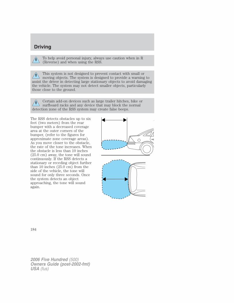
To help avoid personal injury, always use caution when in R(Reverse) and when using the RSS.
This system is not designed to prevent contact with small ormoving objects. The system is designed to provide a warning to
assist the driver in detecting large stationary objects to avoid damagingthe vehicle. The system may not detect smaller objects, particularlythose close to the ground.
Certain add-on devices such as large trailer hitches, bike orsurfboard racks and any device that may block the normal
detection zone of the RSS system may create false beeps.
The RSS detects obstacles up to sixfeet (two meters) from the rearbumper with a decreased coveragearea at the outer corners of thebumper, (refer to the figures forapproximate zone coverage areas).As you move closer to the obstacle,the rate of the tone increases. Whenthe obstacle is less than 10 inches(25.0 cm) away, the tone will soundcontinuously. If the RSS detects astationary or receding object furtherthan 10 inches (25.0 cm) from theside of the vehicle, the tone willsound for only three seconds. Oncethe system detects an objectapproaching, the tone will soundagain.
2006 Five Hundred (500)Owners Guide (post-2002-fmt)USA (fus)
Driving
184
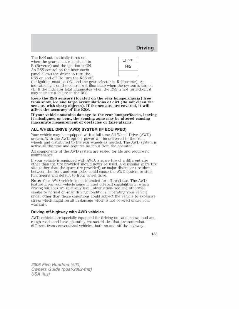
The RSS automatically turns onwhen the gear selector is placed inR (Reverse) and the ignition is ON.An RSS control on the instrumentpanel allows the driver to turn theRSS on and off. To turn the RSS off,the ignition must be ON, and the gear selector in R (Reverse). Anindicator light on the control will illuminate when the system is turnedoff. If the indicator light illuminates when the RSS is not turned off, itmay indicate a failure in the RSS.Keep the RSS sensors (located on the rear bumper/fascia) freefrom snow, ice and large accumulations of dirt (do not clean thesensors with sharp objects). If the sensors are covered, it willaffect the accuracy of the RSS.
If your vehicle sustains damage to the rear bumper/fascia, leavingit misaligned or bent, the sensing zone may be altered causinginaccurate measurement of obstacles or false alarms.
ALL WHEEL DRIVE (AWD) SYSTEM (IF EQUIPPED)Your vehicle may be equipped with a full-time All Wheel Drive (AWD)system. With the AWD option, power will be delivered to the frontwheels and distributed to the rear wheels as needed. The AWD system isactive all the time and requires no input from the operator.All components of the AWD system are sealed for life and require nomaintenance.If your vehicle is equipped with AWD, a spare tire of a different sizeother than the tire provided should never be used. A dissimilar spare tiresize (other than the spare tire provided) or major dissimilar tire sizesbetween the front and rear axles could cause the AWD system to stopfunctioning and default to front wheel drive.Note: Your AWD vehicle is not intended for off-road use. The AWDfeature gives your vehicle some limited off-road capabilities in whichdriving surfaces are relatively level, obstruction-free and otherwisesimilar to normal on-road driving conditions. Operating your vehicleunder other than those conditions could subject the vehicle to excessivestress which might result in damage which is not covered under yourwarranty.
Driving off-highway with AWD vehiclesAWD vehicles are specially equipped for driving on sand, snow, mud andrough roads and have operating characteristics that are somewhatdifferent from conventional vehicles, both on and off the highway.
2006 Five Hundred (500)Owners Guide (post-2002-fmt)USA (fus)
Driving
185
When driving at slow speeds off-highway under high outsidetemperatures, use L (Low) gear when possible. L (Low) gear operationwill maximize the engine and transmission cooling capability.
Under severe operating conditions, the A/C may cycle on and off toprotect overheating of the engine.
Basic operating principles
• Drive slower in strong crosswinds which can affect the normal steeringcharacteristics of your vehicle.
• Be extremely careful when driving on pavement made slippery byloose sand, water, gravel, snow or ice.
If your vehicle goes off the edge of the pavement• If your vehicle goes off the edge of the pavement, slow down, but
avoid severe brake application, ease the vehicle back onto thepavement only after reducing your speed. Do not turn the steeringwheel too sharply while returning to the road surface.
• It may be safer to stay on the apron or shoulder of the road and slowdown gradually before returning to the pavement. You may losecontrol if you do not slow down or if you turn the steering wheel toosharply or abruptly.
• It often may be less risky to strike small objects, such as highwayreflectors, with minor damage to your vehicle rather than attempt asudden return to the pavement which could cause the vehicle to slidesideways out of control or rollover. Remember, your safety and thesafety of others should be your primary concern.
If your vehicle gets stuckIf your vehicle gets stuck in mud or snow it may be rocked out byshifting between forward and reverse gears, stopping between shifts, in asteady pattern. Press lightly on the accelerator in each gear.
If your vehicle is equipped with Traction Control�, it may be beneficialto disengage the Traction Control� system while attempting to rock thevehicle.
Do not rock the vehicle if the engine is not at normal operatingtemperature or damage to the transmission may occur.
Do not rock the vehicle for more than a few minutes or damageto the transmission and tires may occur or the engine mayoverheat.
2006 Five Hundred (500)Owners Guide (post-2002-fmt)USA (fus)
Driving
186
Always set the parking brake fully and make sure the gearshift islatched in P (Park). Turn the ignition to the LOCK position and
remove the key whenever you leave your vehicle.
If the parking brake is fully released, but the brake warning lampremains illuminated, the brakes may not be working properly.
See your authorized dealer.
Do not spin the wheels at over 35 mph (56 km/h). The tires mayfail and injure a passenger or bystander.
Emergency maneuvers
• In an unavoidable emergency situation where a sudden sharp turnmust be made, remember to avoid “over-driving” your vehicle (i.e.,turn the steering wheel only as rapidly and as far as required to avoidthe emergency). Excessive steering will result in less vehicle control,not more. Additionally, smooth variations of the accelerator and/orbrake pedal pressure should be utilized if changes in vehicle speed arecalled for. Avoid abrupt steering, acceleration or braking which couldresult in an increased risk of loss of vehicle control, vehicle rolloverand/or personal injury. Use all available road surface to return thevehicle to a safe direction of travel.
• In the event of an emergency stop, avoid skidding the tires and do notattempt any sharp steering wheel movements.
• If the vehicle goes from one type of surface to another (i.e., fromconcrete to gravel) there will be a change in the way the vehicleresponds to a maneuver (steering, acceleration or braking). Again,avoid these abrupt inputs.
2006 Five Hundred (500)Owners Guide (post-2002-fmt)USA (fus)
Driving
187
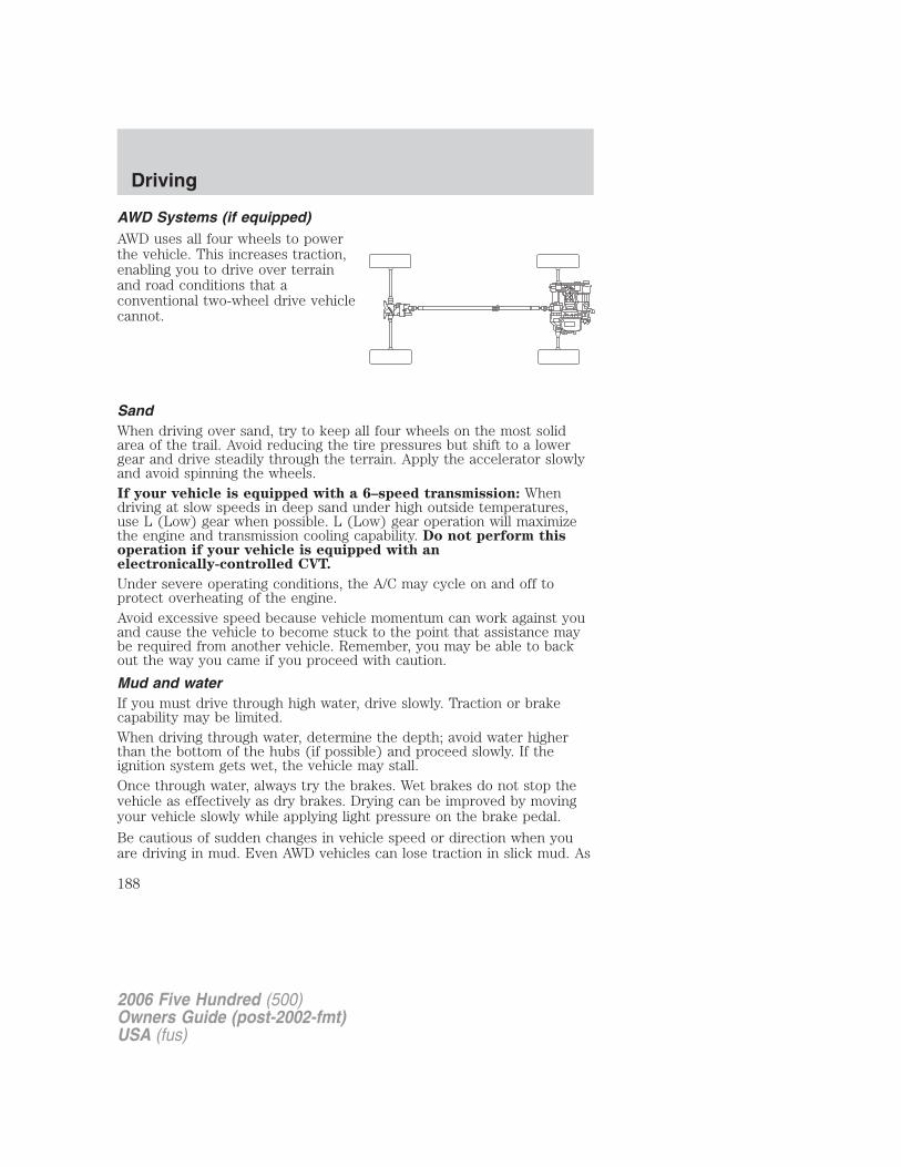
AWD Systems (if equipped)AWD uses all four wheels to powerthe vehicle. This increases traction,enabling you to drive over terrainand road conditions that aconventional two-wheel drive vehiclecannot.
SandWhen driving over sand, try to keep all four wheels on the most solidarea of the trail. Avoid reducing the tire pressures but shift to a lowergear and drive steadily through the terrain. Apply the accelerator slowlyand avoid spinning the wheels.If your vehicle is equipped with a 6–speed transmission: Whendriving at slow speeds in deep sand under high outside temperatures,use L (Low) gear when possible. L (Low) gear operation will maximizethe engine and transmission cooling capability. Do not perform thisoperation if your vehicle is equipped with anelectronically-controlled CVT.
Under severe operating conditions, the A/C may cycle on and off toprotect overheating of the engine.Avoid excessive speed because vehicle momentum can work against youand cause the vehicle to become stuck to the point that assistance maybe required from another vehicle. Remember, you may be able to backout the way you came if you proceed with caution.
Mud and waterIf you must drive through high water, drive slowly. Traction or brakecapability may be limited.When driving through water, determine the depth; avoid water higherthan the bottom of the hubs (if possible) and proceed slowly. If theignition system gets wet, the vehicle may stall.Once through water, always try the brakes. Wet brakes do not stop thevehicle as effectively as dry brakes. Drying can be improved by movingyour vehicle slowly while applying light pressure on the brake pedal.
Be cautious of sudden changes in vehicle speed or direction when youare driving in mud. Even AWD vehicles can lose traction in slick mud. As
2006 Five Hundred (500)Owners Guide (post-2002-fmt)USA (fus)
Driving
188
when you are driving over sand, apply the accelerator slowly and avoidspinning your wheels. If the vehicle does slide, steer in the direction ofthe slide until you regain control of the vehicle.
If the transmission, AWD system components or axles are submerged inwater, their fluids should be checked and changed, if necessary.
Driving through deep water may damage the transmission.
If the front or rear axle is submerged in water, the axle lubricant andPTU (Power Transfer Unit) lubricant should be checked and changed ifnecessary.
After driving through mud, clean off residue stuck to rotating driveshaftsand tires. Excess mud stuck on tires and rotating driveshafts causes animbalance that could damage drive components.
“Tread Lightly” is an educationalprogram designed to increase publicawareness of land-use regulationsand responsibilities in our nationswilderness areas. Ford MotorCompany joins the U.S. Forest Service and the Bureau of LandManagement in encouraging you to help preserve our national forest andother public and private lands by “treading lightly.”
Driving on hilly or sloping terrainAlthough natural obstacles may make it necessary to travel diagonally upor down a hill or steep incline, you should always try to drive straight upor straight down. Avoid driving crosswise or turning on steepslopes or hills. A danger lies in losing traction, slipping sideways andpossibly rolling over. Whenever driving on a hill, determine beforehandthe route you will use. Do not drive over the crest of a hill withoutseeing what conditions are on the other side. Do not drive in reverseover a hill without the aid of an observer.
When climbing a steep slope or hill, start in a lower gear rather thandownshifting to a lower gear from a higher gear once the ascent hasstarted. This reduces strain on the engine and the possibility of stalling.
If you do stall out, Do not try to turnaround because you might roll over.It is better to back down to a safe location.
Apply just enough power to the wheels to climb the hill. Too muchpower will cause the tires to slip, spin or lose traction, resulting in loss ofvehicle control.
2006 Five Hundred (500)Owners Guide (post-2002-fmt)USA (fus)
Driving
189
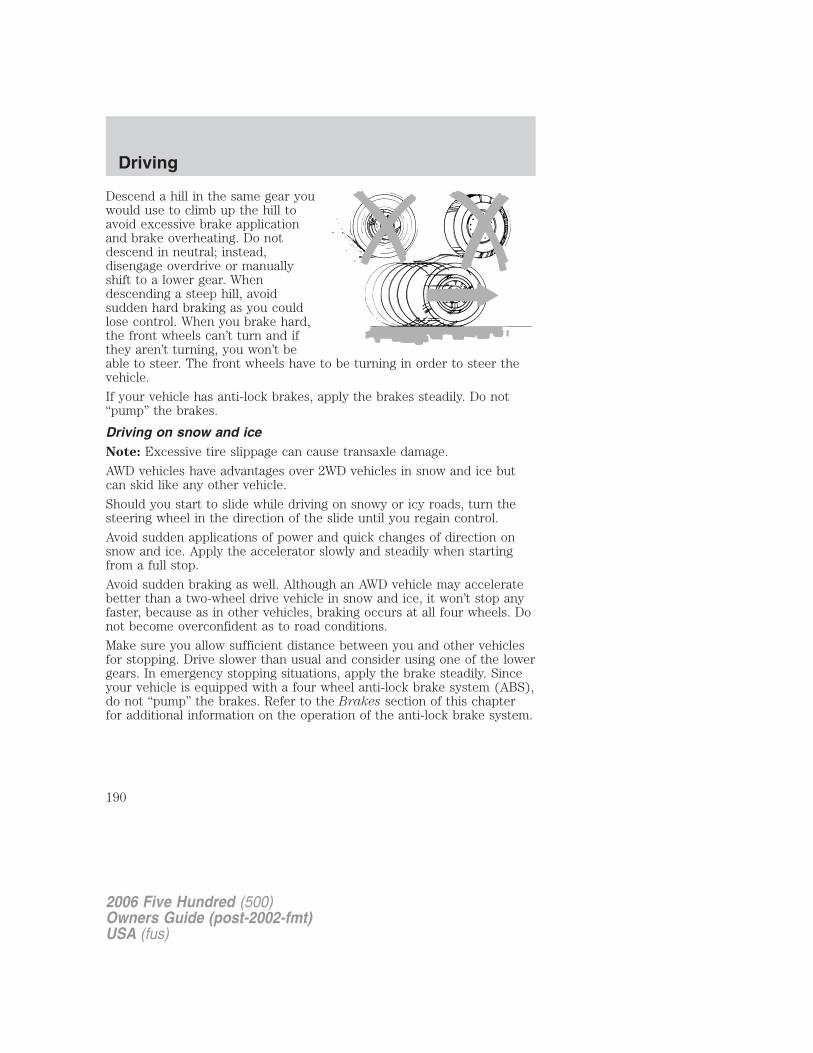
Descend a hill in the same gear youwould use to climb up the hill toavoid excessive brake applicationand brake overheating. Do notdescend in neutral; instead,disengage overdrive or manuallyshift to a lower gear. Whendescending a steep hill, avoidsudden hard braking as you couldlose control. When you brake hard,the front wheels can’t turn and ifthey aren’t turning, you won’t beable to steer. The front wheels have to be turning in order to steer thevehicle.
If your vehicle has anti-lock brakes, apply the brakes steadily. Do not“pump” the brakes.
Driving on snow and iceNote: Excessive tire slippage can cause transaxle damage.
AWD vehicles have advantages over 2WD vehicles in snow and ice butcan skid like any other vehicle.
Should you start to slide while driving on snowy or icy roads, turn thesteering wheel in the direction of the slide until you regain control.
Avoid sudden applications of power and quick changes of direction onsnow and ice. Apply the accelerator slowly and steadily when startingfrom a full stop.
Avoid sudden braking as well. Although an AWD vehicle may acceleratebetter than a two-wheel drive vehicle in snow and ice, it won’t stop anyfaster, because as in other vehicles, braking occurs at all four wheels. Donot become overconfident as to road conditions.
Make sure you allow sufficient distance between you and other vehiclesfor stopping. Drive slower than usual and consider using one of the lowergears. In emergency stopping situations, apply the brake steadily. Sinceyour vehicle is equipped with a four wheel anti-lock brake system (ABS),do not “pump” the brakes. Refer to the Brakes section of this chapterfor additional information on the operation of the anti-lock brake system.
2006 Five Hundred (500)Owners Guide (post-2002-fmt)USA (fus)
Driving
190
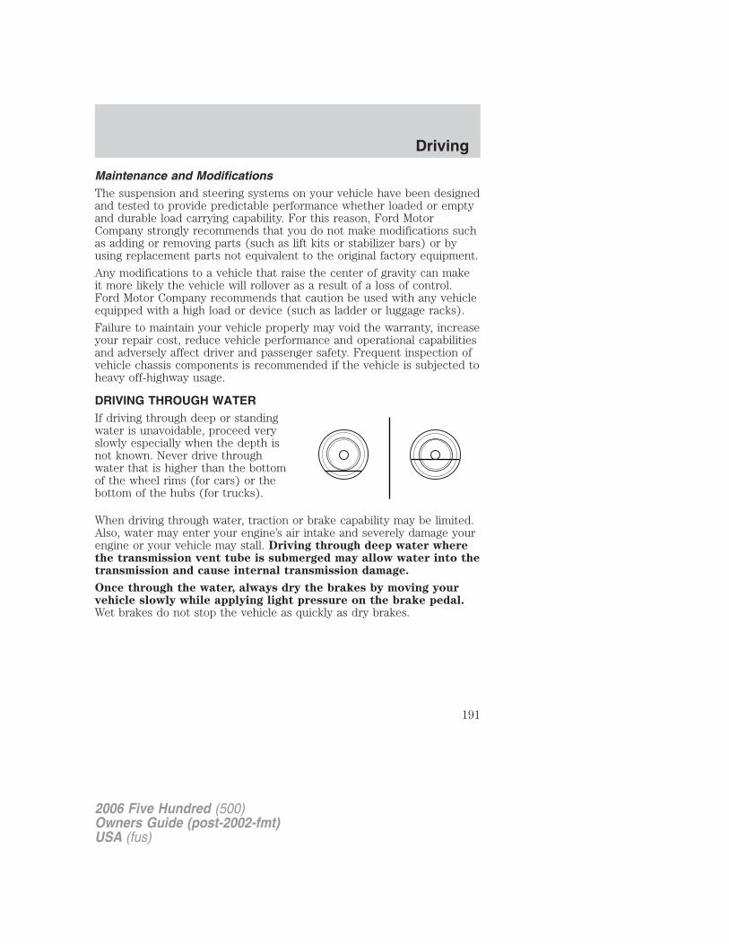
Maintenance and ModificationsThe suspension and steering systems on your vehicle have been designedand tested to provide predictable performance whether loaded or emptyand durable load carrying capability. For this reason, Ford MotorCompany strongly recommends that you do not make modifications suchas adding or removing parts (such as lift kits or stabilizer bars) or byusing replacement parts not equivalent to the original factory equipment.
Any modifications to a vehicle that raise the center of gravity can makeit more likely the vehicle will rollover as a result of a loss of control.Ford Motor Company recommends that caution be used with any vehicleequipped with a high load or device (such as ladder or luggage racks).
Failure to maintain your vehicle properly may void the warranty, increaseyour repair cost, reduce vehicle performance and operational capabilitiesand adversely affect driver and passenger safety. Frequent inspection ofvehicle chassis components is recommended if the vehicle is subjected toheavy off-highway usage.
DRIVING THROUGH WATERIf driving through deep or standingwater is unavoidable, proceed veryslowly especially when the depth isnot known. Never drive throughwater that is higher than the bottomof the wheel rims (for cars) or thebottom of the hubs (for trucks).
When driving through water, traction or brake capability may be limited.Also, water may enter your engine’s air intake and severely damage yourengine or your vehicle may stall. Driving through deep water wherethe transmission vent tube is submerged may allow water into thetransmission and cause internal transmission damage.
Once through the water, always dry the brakes by moving yourvehicle slowly while applying light pressure on the brake pedal.Wet brakes do not stop the vehicle as quickly as dry brakes.
2006 Five Hundred (500)Owners Guide (post-2002-fmt)USA (fus)
Driving
191
ROADSIDE ASSISTANCE
Getting roadside assistanceTo fully assist you should you have a vehicle concern, Ford MotorCompany offers a complimentary roadside assistance program. Thisprogram is separate from the New Vehicle Limited Warranty. The serviceis available:
• 24–hours, seven days a week
• for the New Vehicle Limited Warranty period of three years or 36,000miles (60,000 km), whichever occurs first on Ford and Mercuryvehicles, and four years or 50,000 miles (80,000 km) on Lincolnvehicles.
Roadside assistance will cover:
• a flat tire change with a good spare (except Ford GT which has a tireinflation kit)
• battery jump start
• lock-out assistance (key replacement cost is the customer’sresponsibility)
• fuel delivery – Independent Service Contractors, if not prohibited bystate, local or municipal law shall deliver up to 2.0 gallons (7.5L) ofgasoline or 5 gallons (18.9L) of diesel fuel to a disabled vehicle. Fueldelivery service is limited to two no-charge occurrences within a12-month period.
• winch out – available within 100 feet (30.5 meters) of a paved orcounty maintained road, no recoveries.
• towing – Ford/Mercury/Lincoln eligible vehicle towed to an authorizeddealer within 35 miles (56.3 km) of the disablement location or to thenearest authorized dealer. If a member requests to be towed to anauthorized dealer more than 35 miles (56.3 km) from the disablementlocation, the member shall be responsible for any mileage costs inexcess of 35 miles (56.3 km).
Trailers shall be covered up to $100 if the disabled eligible vehiclerequires service at the nearest authorized dealer. If the trailer is disabled,but the towing vehicle is operational, the trailer does not qualify for anyroadside services.
2006 Five Hundred (500)Owners Guide (post-2002-fmt)USA (fus)
Roadside Emergencies
192
Canadian customers refer to your Owner Information Guide forinformation on:
• coverage period
• exact fuel amounts
• towing of your disabled vehicle
• emergency travel expense reimbursement
• travel planning benefits
Using roadside assistance
Complete the roadside assistance identification card and place it in yourwallet for quick reference. In the United States, this card is found in theOwner Guide portfolio in the glove compartment. In Canada, the card isfound in the Owner Information Guide in the glove compartment.
U.S. Ford or Mercury vehicle customers who require roadside assistance,call 1–800–241–3673; Lincoln vehicle customers call 1–800–521–4140.
Canadian customers who require roadside assistance, call1–800–665–2006.
If you need to arrange roadside assistance for yourself, Ford MotorCompany will reimburse a reasonable amount. To obtain reimbursementinformation, U.S. Ford or Mercury vehicles customers call1–800–241–3673; Lincoln vehicle customers call 1–800–521–4140.
Canadian customers who need to obtain reimbursement information, call1–800–665–2006.
Roadside coverage beyond basic warranty
In the United States, you may purchase additional roadside assistancecoverage beyond this period through the Ford Auto Club by contactingyour authorized dealer.
Similarly in Canada, for uninterrupted Roadside Assistance coverage, youmay purchase extended coverage prior to your Basic Warranty’s RoadsideAssistance expiring. For more information and enrollment, contact1–877–294–2582 or visit our website at www.ford.ca.
2006 Five Hundred (500)Owners Guide (post-2002-fmt)USA (fus)
Roadside Emergencies
193
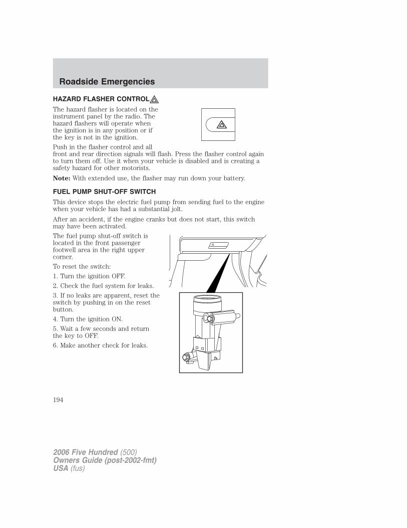
HAZARD FLASHER CONTROL
The hazard flasher is located on theinstrument panel by the radio. Thehazard flashers will operate whenthe ignition is in any position or ifthe key is not in the ignition.
Push in the flasher control and allfront and rear direction signals will flash. Press the flasher control againto turn them off. Use it when your vehicle is disabled and is creating asafety hazard for other motorists.
Note: With extended use, the flasher may run down your battery.
FUEL PUMP SHUT-OFF SWITCH
This device stops the electric fuel pump from sending fuel to the enginewhen your vehicle has had a substantial jolt.
After an accident, if the engine cranks but does not start, this switchmay have been activated.
The fuel pump shut-off switch islocated in the front passengerfootwell area in the right uppercorner.
To reset the switch:
1. Turn the ignition OFF.
2. Check the fuel system for leaks.
3. If no leaks are apparent, reset theswitch by pushing in on the resetbutton.
4. Turn the ignition ON.
5. Wait a few seconds and returnthe key to OFF.
6. Make another check for leaks.
2006 Five Hundred (500)Owners Guide (post-2002-fmt)USA (fus)
Roadside Emergencies
194
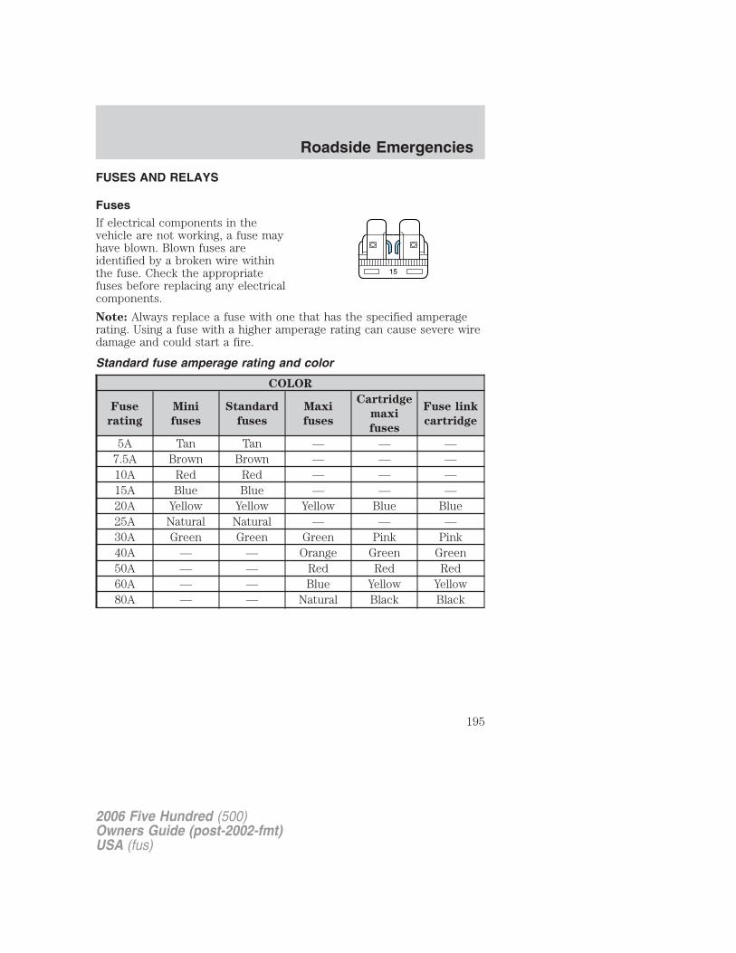
FUSES AND RELAYS
FusesIf electrical components in thevehicle are not working, a fuse mayhave blown. Blown fuses areidentified by a broken wire withinthe fuse. Check the appropriatefuses before replacing any electricalcomponents.
Note: Always replace a fuse with one that has the specified amperagerating. Using a fuse with a higher amperage rating can cause severe wiredamage and could start a fire.
Standard fuse amperage rating and color
COLOR
Fuse
rating
Mini
fuses
Standard
fuses
Maxi
fuses
Cartridge
maxi
fuses
Fuse link
cartridge
5A Tan Tan — — —7.5A Brown Brown — — —10A Red Red — — —15A Blue Blue — — —20A Yellow Yellow Yellow Blue Blue25A Natural Natural — — —30A Green Green Green Pink Pink40A — — Orange Green Green50A — — Red Red Red60A — — Blue Yellow Yellow80A — — Natural Black Black
15
2006 Five Hundred (500)Owners Guide (post-2002-fmt)USA (fus)
Roadside Emergencies
195
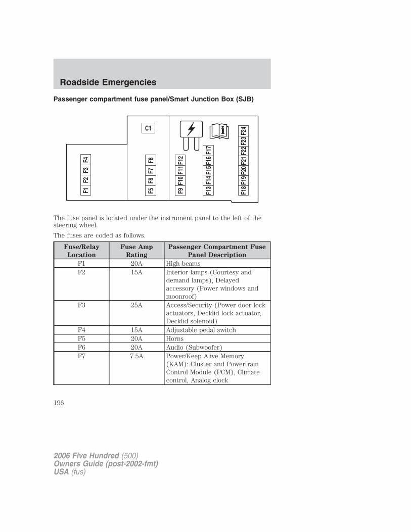
Passenger compartment fuse panel/Smart Junction Box (SJB)
The fuse panel is located under the instrument panel to the left of thesteering wheel.
The fuses are coded as follows.
Fuse/Relay
Location
Fuse Amp
Rating
Passenger Compartment Fuse
Panel Description
F1 20A High beamsF2 15A Interior lamps (Courtesy and
demand lamps), Delayedaccessory (Power windows andmoonroof)
F3 25A Access/Security (Power door lockactuators, Decklid lock actuator,Decklid solenoid)
F4 15A Adjustable pedal switchF5 20A HornsF6 20A Audio (Subwoofer)F7 7.5A Power/Keep Alive Memory
(KAM): Cluster and PowertrainControl Module (PCM), Climatecontrol, Analog clock
2006 Five Hundred (500)Owners Guide (post-2002-fmt)USA (fus)
Roadside Emergencies
196
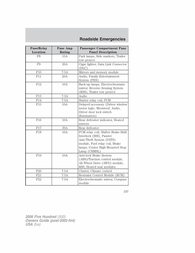
Fuse/Relay
Location
Fuse Amp
Rating
Passenger Compartment Fuse
Panel Description
F8 15A Park lamps, Side markers, Trailertow protect
F9 20A Cigar lighter, Data Link Connector(DLC)
F10 7.5A Mirrors and memory moduleF11 20A Audio, Family Entertainment
System (FES)F12 10A Back-up lamps, Electrochromatic
mirror, Reverse Sensing System(RSS), Trailer tow protect
F13 7.5A AudioF14 7.5A Starter relay coil, PCMF15 10A Delayed accessory (Driver window
motor logic, Moonroof, Audio,Driver door lock switchillumination)
F16 10A Rear defroster indicator, Heatedmirrors
F17 30A Rear defrosterF18 10A PCM relay coil, Shifter Brake-Shift
Interlock (BSI), PassiveAnti-Theft System (PATS)module, Fuel relay coil, Brakelamps, Center High-Mounted StopLamp (CHMSL)
F19 10A Anti-lock Brake System(ABS)/Traction control module,All Wheel Drive (AWD) module,RSS, Heated seat modules
F20 7.5A Cluster, Climate controlF21 7.5A Restraint Control Module (RCM)F22 7.5A Electrochromatic mirror, Compass
module
2006 Five Hundred (500)Owners Guide (post-2002-fmt)USA (fus)
Roadside Emergencies
197
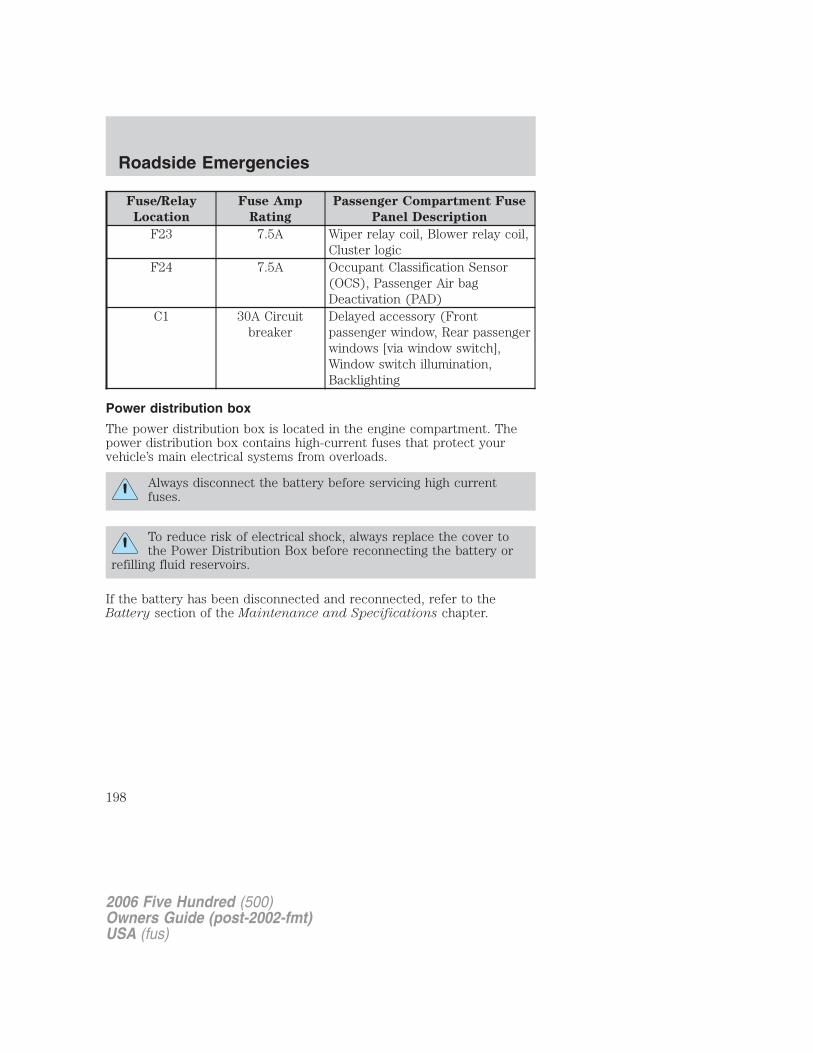
Fuse/Relay
Location
Fuse Amp
Rating
Passenger Compartment Fuse
Panel Description
F23 7.5A Wiper relay coil, Blower relay coil,Cluster logic
F24 7.5A Occupant Classification Sensor(OCS), Passenger Air bagDeactivation (PAD)
C1 30A Circuitbreaker
Delayed accessory (Frontpassenger window, Rear passengerwindows [via window switch],Window switch illumination,Backlighting
Power distribution box
The power distribution box is located in the engine compartment. Thepower distribution box contains high-current fuses that protect yourvehicle’s main electrical systems from overloads.
Always disconnect the battery before servicing high currentfuses.
To reduce risk of electrical shock, always replace the cover tothe Power Distribution Box before reconnecting the battery or
refilling fluid reservoirs.
If the battery has been disconnected and reconnected, refer to theBattery section of the Maintenance and Specifications chapter.
2006 Five Hundred (500)Owners Guide (post-2002-fmt)USA (fus)
Roadside Emergencies
198
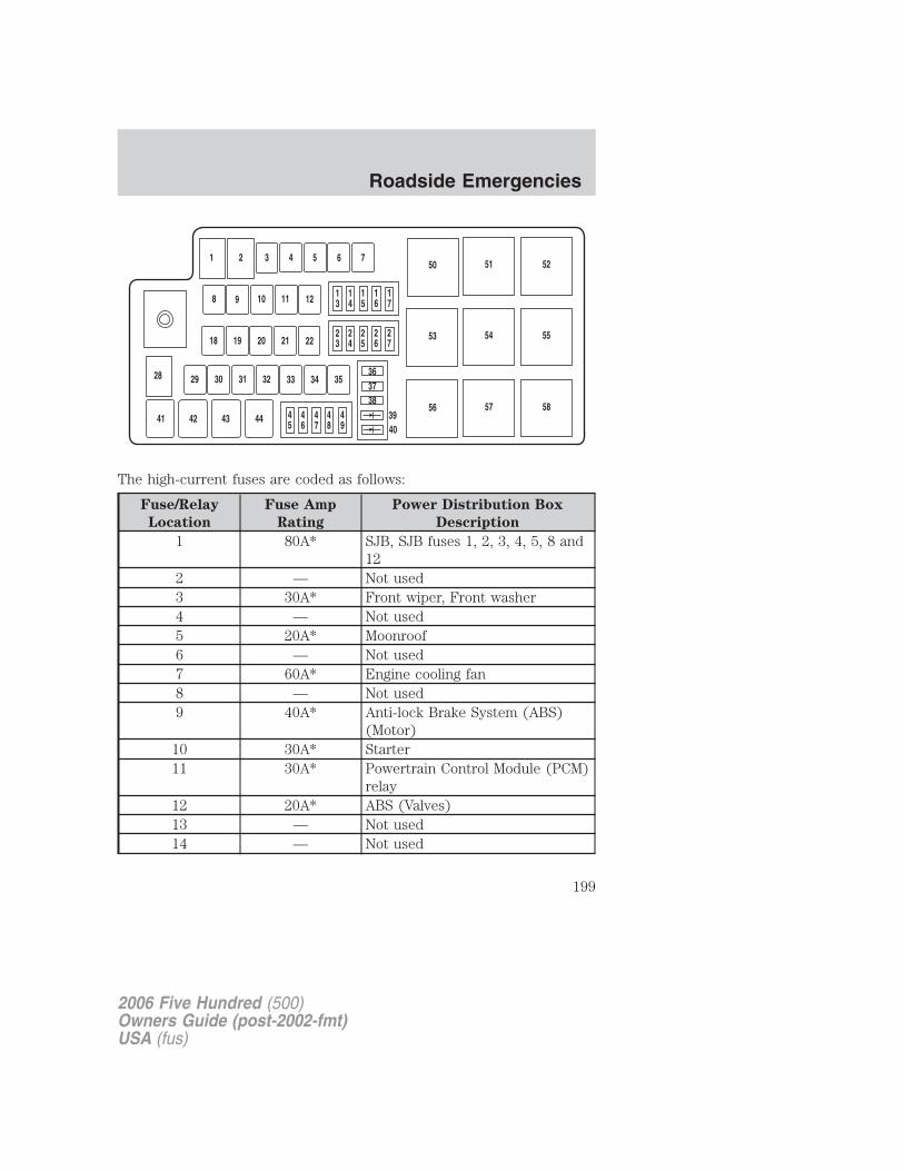
The high-current fuses are coded as follows:
Fuse/Relay
Location
Fuse Amp
Rating
Power Distribution Box
Description
1 80A* SJB, SJB fuses 1, 2, 3, 4, 5, 8 and12
2 — Not used3 30A* Front wiper, Front washer4 — Not used5 20A* Moonroof6 — Not used7 60A* Engine cooling fan8 — Not used9 40A* Anti-lock Brake System (ABS)
(Motor)10 30A* Starter11 30A* Powertrain Control Module (PCM)
relay12 20A* ABS (Valves)13 — Not used14 — Not used
2006 Five Hundred (500)Owners Guide (post-2002-fmt)USA (fus)
Roadside Emergencies
199
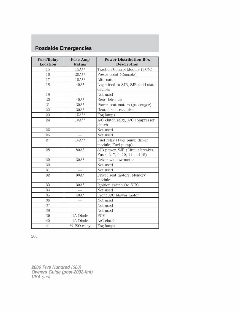
Fuse/Relay
Location
Fuse Amp
Rating
Power Distribution Box
Description
15 15A** Traction Control Module (TCM)16 20A** Power point (Console)17 10A** Alternator18 40A* Logic feed to SJB, SJB solid state
devices19 — Not used20 40A* Rear defroster21 30A* Power seat motors (passenger)22 30A* Heated seat modules23 15A** Fog lamps24 10A** A/C clutch relay, A/C compressor
clutch25 — Not used26 — Not used27 15A** Fuel relay (Fuel pump driver
module, Fuel pump)28 80A* SJB power, SJB (Circuit breaker,
Fuses 6, 7, 9, 10, 11 and 15)29 30A* Driver window motor30 — Not used31 — Not used32 30A* Driver seat motors, Memory
module33 30A* Ignition switch (to SJB)34 — Not used35 40A* Front A/C blower motor36 — Not used37 — Not used38 — Not used39 1A Diode PCM40 1A Diode A/C clutch41 1⁄2 ISO relay Fog lamps
2006 Five Hundred (500)Owners Guide (post-2002-fmt)USA (fus)
Roadside Emergencies
200
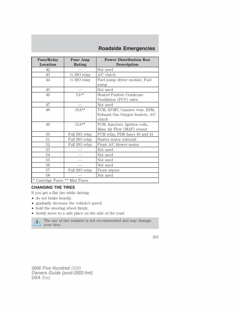
Fuse/Relay
Location
Fuse Amp
Rating
Power Distribution Box
Description
42 — Not used43 1⁄2 ISO relay A/C clutch44 1⁄2 ISO relay Fuel pump driver module, Fuel
pump45 — Not used46 5A** Heated Positive Crankcase
Ventilation (PCV) valve47 — Not used48 10A** TCM, EVMV, Canister vent, ESM,
Exhaust Gas Oxygen heaters, A/Cclutch
49 15A** PCM, Injectors, Ignition coils,Mass Air Flow (MAF) sensor
50 Full ISO relay PCM relay, PDB fuses 40 and 4151 Full ISO relay Starter motor solenoid52 Full ISO relay Front A/C blower motor53 — Not used54 — Not used55 — Not used56 — Not used57 Full ISO relay Front wipers58 — Not used
* Cartridge Fuses ** Mini Fuses
CHANGING THE TIRESIf you get a flat tire while driving:• do not brake heavily.• gradually decrease the vehicle’s speed.• hold the steering wheel firmly.• slowly move to a safe place on the side of the road.
The use of tire sealants is not recommended and may damageyour tires.
2006 Five Hundred (500)Owners Guide (post-2002-fmt)USA (fus)
Roadside Emergencies
201
Dissimilar spare tire/wheel information
Failure to follow these guidelines could result in an increasedrisk of loss of vehicle control, injury or death.
If you have a dissimilar spare tire/wheel, then it is intended fortemporary use only. This means that if you need to use it, you shouldreplace it as soon as possible with a road tire/wheel that is the same sizeand type as the road tires and wheels that were originally provided byFord. If the dissimilar spare tire or wheel is damaged, it should bereplaced rather than repaired.
A dissimilar spare tire/wheel is defined as a spare tire and/or wheel thatis different in brand, size or appearance from the road tires and wheelsand can be one of three types:
1. T-type mini-spare: This spare tire begins with the letter “T” for tiresize and may have “Temporary Use Only” molded in the sidewall
2. Full-size dissimilar spare with label on wheel: This spare tire hasa label on the wheel that states: “THIS TIRE AND WHEEL FORTEMPORARY USE ONLY”
When driving with one of the dissimilar spare tires listed above, do not:
• Exceed 50 mph (80 km/h)
• Load the vehicle beyond maximum vehicle load rating listed on theSafety Compliance Label
• Tow a trailer
• Use snow chains on the end of the vehicle with the dissimilar sparetire
• Use more than one dissimilar spare tire at a time
• Use commercial car washing equipment
• Try to repair the dissimilar spare tire
Use of one of the dissimilar spare tires listed above at any one wheellocation can lead to impairment of the following:
• Handling, stability and braking performance
• Comfort and noise
• Ground clearance and parking at curbs
• Winter weather driving capability
• Wet weather driving capability
2006 Five Hundred (500)Owners Guide (post-2002-fmt)USA (fus)
Roadside Emergencies
202
For vehicles equipped with 4WD, it is not recommended that the vehiclebe operated in 4WD modes with a temporary emergency spare tire. If4WD operation is necessary, do not operate above speeds of 10 mph (16km/h) or for distances above 50 miles (80 km).
3. Full-size dissimilar spare without label on wheel
When driving with the full-size dissimilar spare tire/wheel, do not:
• Exceed 70 mph (113 km/h)
• Use more than one dissimilar spare tire/wheel at a time
• Use commercial car washing equipment
• Use snow chains on the end of the vehicle with the dissimilar sparetire/wheel
The usage of a full-size dissimilar spare tire/wheel can lead toimpairment of the following:
• Handling, stability and braking performance
• Comfort and noise
• Ground clearance and parking at curbs
• Winter weather driving capability
• Wet weather driving capability
• All-Wheel driving capability (if applicable)
• Load leveling adjustment (if applicable)
When driving with the full-size dissimilar spare tire/wheel additionalcaution should be given to:
• Towing a trailer
• Driving vehicles equipped with a camper body
• Driving vehicles with a load on the cargo rack
Drive cautiously when using a full-size dissimilar spare tire/wheel andseek service as soon as possible.
2006 Five Hundred (500)Owners Guide (post-2002-fmt)USA (fus)
Roadside Emergencies
203
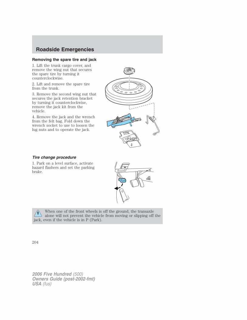
Removing the spare tire and jack1. Lift the trunk cargo cover, andremove the wing nut that securesthe spare tire by turning itcounterclockwise.
2. Lift and remove the spare tirefrom the trunk.
3. Remove the second wing nut thatsecures the jack retention bracketby turning it counterclockwise,remove the jack kit from thevehicle.
4. Remove the jack and the wrenchfrom the felt bag. Fold down thewrench socket to use to loosen thelug nuts and to operate the jack.
Tire change procedure1. Park on a level surface, activatehazard flashers and set the parkingbrake.
When one of the front wheels is off the ground, the transaxlealone will not prevent the vehicle from moving or slipping off the
jack, even if the vehicle is in P (Park).
2006 Five Hundred (500)Owners Guide (post-2002-fmt)USA (fus)
Roadside Emergencies
204
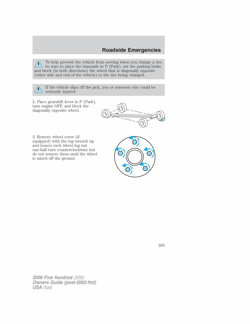
To help prevent the vehicle from moving when you change a tire,be sure to place the transaxle in P (Park), set the parking brake
and block (in both directions) the wheel that is diagonally opposite(other side and end of the vehicle) to the tire being changed.
If the vehicle slips off the jack, you or someone else could beseriously injured.
2. Place gearshift lever in P (Park),turn engine OFF, and block thediagonally opposite wheel.
3. Remove wheel cover (ifequipped) with the lug wrench tipand loosen each wheel lug nutone-half turn counterclockwise butdo not remove them until the wheelis raised off the ground.
2006 Five Hundred (500)Owners Guide (post-2002-fmt)USA (fus)
Roadside Emergencies
205
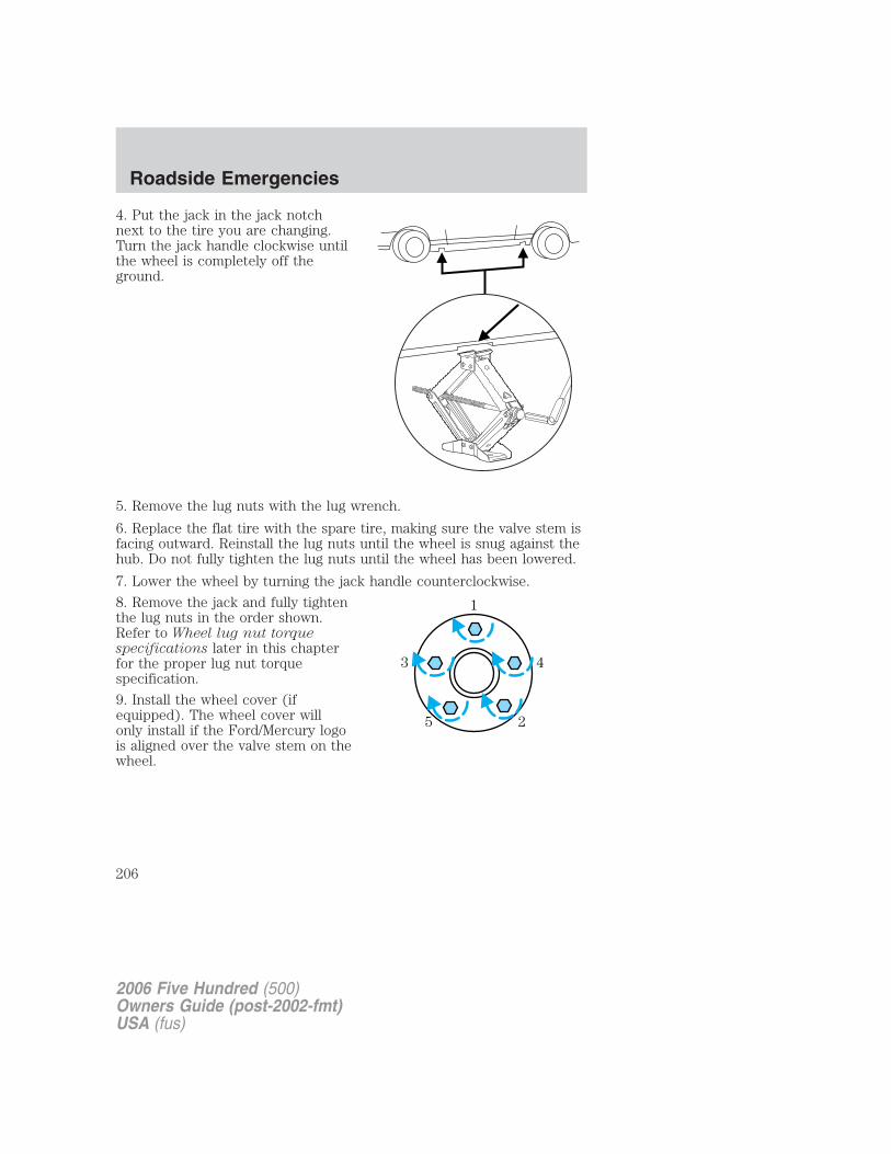
4. Put the jack in the jack notchnext to the tire you are changing.Turn the jack handle clockwise untilthe wheel is completely off theground.
5. Remove the lug nuts with the lug wrench.
6. Replace the flat tire with the spare tire, making sure the valve stem isfacing outward. Reinstall the lug nuts until the wheel is snug against thehub. Do not fully tighten the lug nuts until the wheel has been lowered.
7. Lower the wheel by turning the jack handle counterclockwise.
8. Remove the jack and fully tightenthe lug nuts in the order shown.Refer to Wheel lug nut torquespecifications later in this chapterfor the proper lug nut torquespecification.
9. Install the wheel cover (ifequipped). The wheel cover willonly install if the Ford/Mercury logois aligned over the valve stem on thewheel.
1
43
25
2006 Five Hundred (500)Owners Guide (post-2002-fmt)USA (fus)
Roadside Emergencies
206
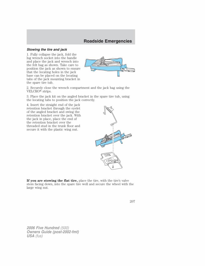
Stowing the tire and jack1. Fully collapse the jack, fold thelug wrench socket into the handleand place the jack and wrench intothe felt bag as shown. Take care toposition the jack as shown to ensurethat the locating holes in the jackbase can be placed on the locatingtabs of the jack mounting bracket inthe spare tire tub.
2. Securely close the wrench compartment and the jack bag using theVELCRO� strips.
3. Place the jack kit on the angled bracket in the spare tire tub, usingthe locating tabs to position the jack correctly.
4. Insert the straight end of the jackretention bracket through the eyeletof the angled bracket and swing theretention bracket over the jack. Withthe jack in place, place the end ofthe retention bracket over thethreaded stud in the trunk floor andsecure it with the plastic wing nut.
If you are stowing the flat tire, place the tire, with the tire’s valvestem facing down, into the spare tire well and secure the wheel with thelarge wing nut.
2006 Five Hundred (500)Owners Guide (post-2002-fmt)USA (fus)
Roadside Emergencies
207
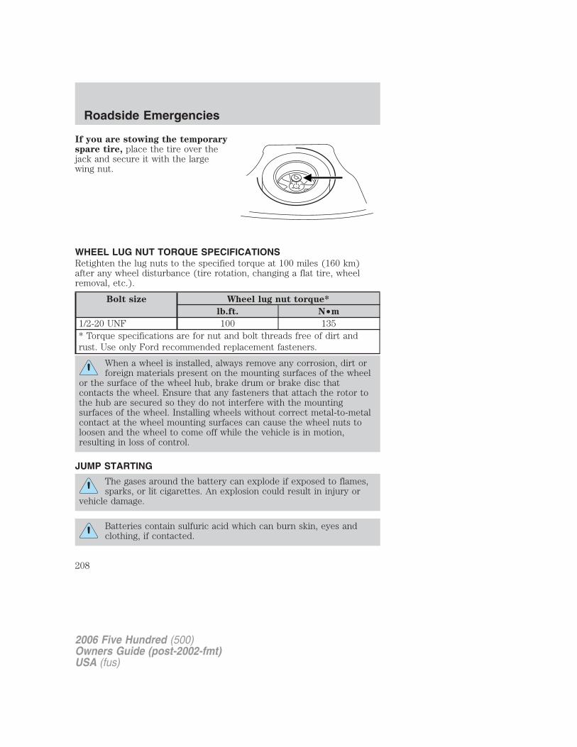
If you are stowing the temporaryspare tire, place the tire over thejack and secure it with the largewing nut.
WHEEL LUG NUT TORQUE SPECIFICATIONSRetighten the lug nuts to the specified torque at 100 miles (160 km)after any wheel disturbance (tire rotation, changing a flat tire, wheelremoval, etc.).
Bolt size Wheel lug nut torque*
lb.ft. N•m
1/2-20 UNF 100 135* Torque specifications are for nut and bolt threads free of dirt andrust. Use only Ford recommended replacement fasteners.
When a wheel is installed, always remove any corrosion, dirt orforeign materials present on the mounting surfaces of the wheel
or the surface of the wheel hub, brake drum or brake disc thatcontacts the wheel. Ensure that any fasteners that attach the rotor tothe hub are secured so they do not interfere with the mountingsurfaces of the wheel. Installing wheels without correct metal-to-metalcontact at the wheel mounting surfaces can cause the wheel nuts toloosen and the wheel to come off while the vehicle is in motion,resulting in loss of control.
JUMP STARTING
The gases around the battery can explode if exposed to flames,sparks, or lit cigarettes. An explosion could result in injury or
vehicle damage.
Batteries contain sulfuric acid which can burn skin, eyes andclothing, if contacted.
2006 Five Hundred (500)Owners Guide (post-2002-fmt)USA (fus)
Roadside Emergencies
208

Do not attempt to push-start your vehicle. Automatic
transmissions do not have push-start capability; doing so may
damage the catalytic converter.
Preparing your vehicle
When the battery is disconnected or a new battery is installed, thetransmission must relearn its shift strategy. As a result, the transmissionmay have firm and/or soft shifts. This operation is considered normal andwill not affect function or durability of the transmission. Over time, theadaptive learning process will fully update transmission operation.
1. Use only a 12–volt supply to start your vehicle.
2. Do not disconnect the battery of the disabled vehicle as this coulddamage the vehicle’s electrical system.
3. Park the booster vehicle close to the hood of the disabled vehiclemaking sure the two vehicles do not touch. Set the parking brake onboth vehicles and stay clear of the engine cooling fan and other movingparts.
4. Check all battery terminals and remove any excessive corrosion beforeyou attach the battery cables. Ensure that vent caps are tight and level.
5. Turn the heater fan on in both vehicles to protect any electricalsurges. Turn all other accessories off.
Connecting the jumper cables
1. Connect the positive (+) jumper cable to the positive (+) terminal ofthe discharged battery.
Note: In the illustrations, lightning bolts are used to designate theassisting (boosting) battery.
+–
+–
2006 Five Hundred (500)Owners Guide (post-2002-fmt)USA (fus)
Roadside Emergencies
209
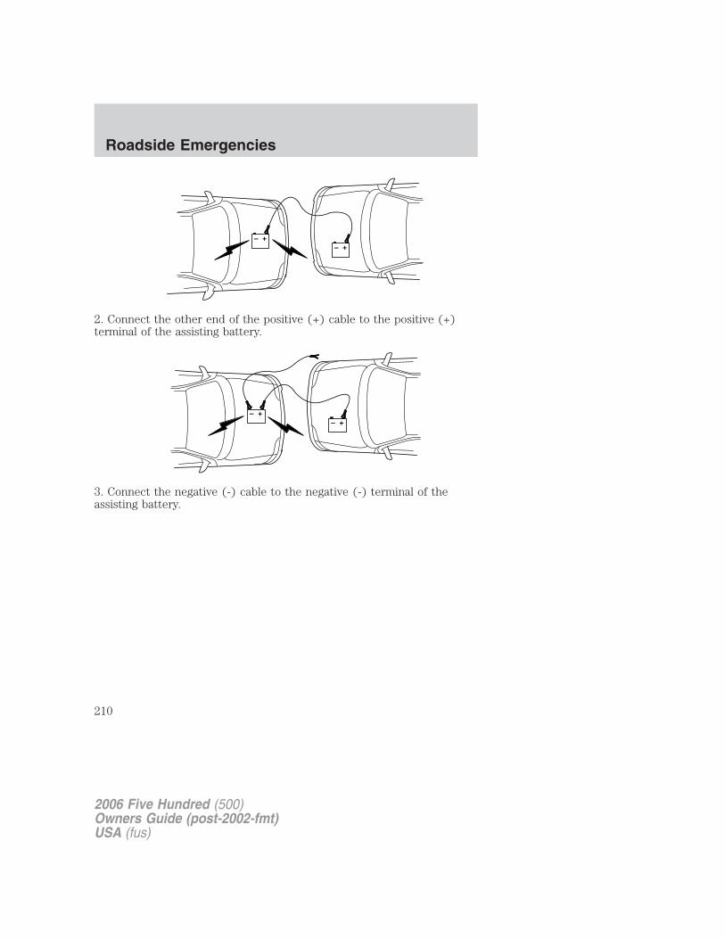
2. Connect the other end of the positive (+) cable to the positive (+)terminal of the assisting battery.
3. Connect the negative (-) cable to the negative (-) terminal of theassisting battery.
+–
+–
+–
+–
2006 Five Hundred (500)Owners Guide (post-2002-fmt)USA (fus)
Roadside Emergencies
210
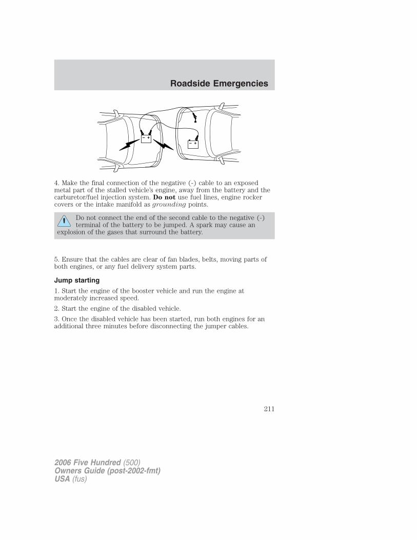
4. Make the final connection of the negative (-) cable to an exposedmetal part of the stalled vehicle’s engine, away from the battery and thecarburetor/fuel injection system. Do not use fuel lines, engine rockercovers or the intake manifold as grounding points.
Do not connect the end of the second cable to the negative (-)terminal of the battery to be jumped. A spark may cause an
explosion of the gases that surround the battery.
5. Ensure that the cables are clear of fan blades, belts, moving parts ofboth engines, or any fuel delivery system parts.
Jump starting
1. Start the engine of the booster vehicle and run the engine atmoderately increased speed.
2. Start the engine of the disabled vehicle.
3. Once the disabled vehicle has been started, run both engines for anadditional three minutes before disconnecting the jumper cables.
+–
+–
2006 Five Hundred (500)Owners Guide (post-2002-fmt)USA (fus)
Roadside Emergencies
211
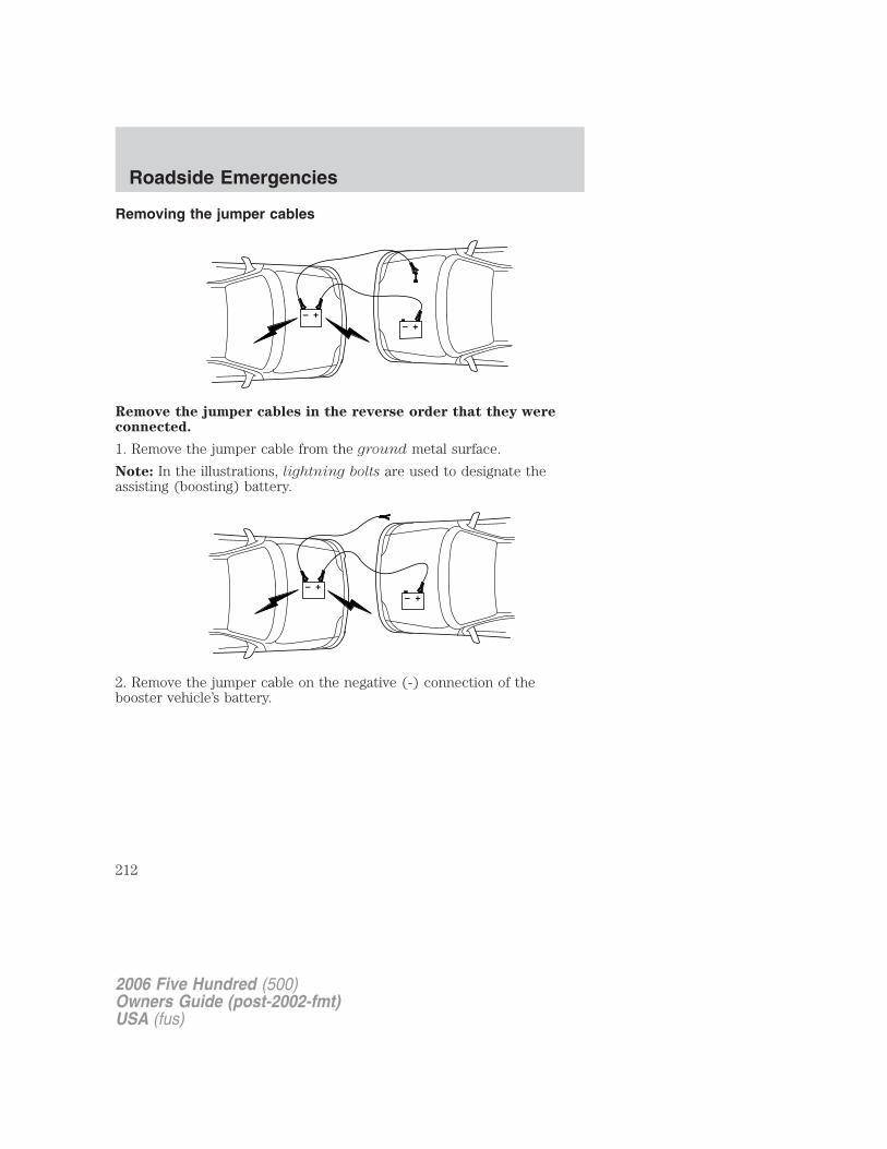
Removing the jumper cables
Remove the jumper cables in the reverse order that they wereconnected.
1. Remove the jumper cable from the ground metal surface.
Note: In the illustrations, lightning bolts are used to designate theassisting (boosting) battery.
2. Remove the jumper cable on the negative (-) connection of thebooster vehicle’s battery.
+–
+–
+–
+–
2006 Five Hundred (500)Owners Guide (post-2002-fmt)USA (fus)
Roadside Emergencies
212
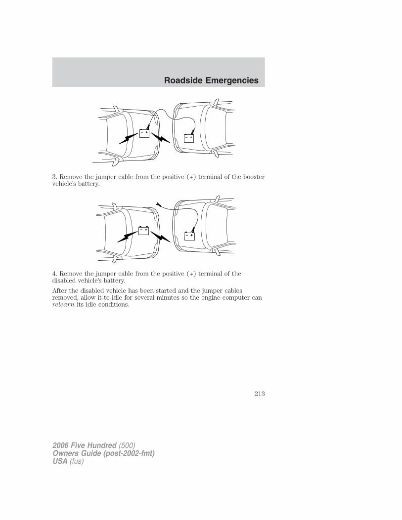
3. Remove the jumper cable from the positive (+) terminal of the boostervehicle’s battery.
4. Remove the jumper cable from the positive (+) terminal of thedisabled vehicle’s battery.
After the disabled vehicle has been started and the jumper cablesremoved, allow it to idle for several minutes so the engine computer canrelearn its idle conditions.
+–
+–
+–
+–
2006 Five Hundred (500)Owners Guide (post-2002-fmt)USA (fus)
Roadside Emergencies
213
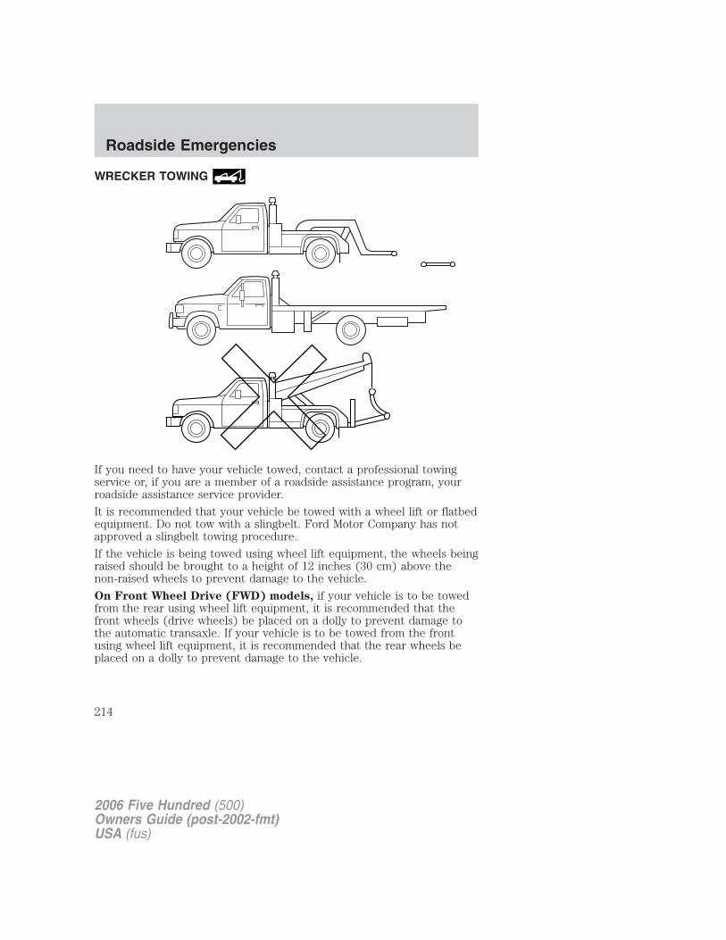
WRECKER TOWING
If you need to have your vehicle towed, contact a professional towingservice or, if you are a member of a roadside assistance program, yourroadside assistance service provider.
It is recommended that your vehicle be towed with a wheel lift or flatbedequipment. Do not tow with a slingbelt. Ford Motor Company has notapproved a slingbelt towing procedure.
If the vehicle is being towed using wheel lift equipment, the wheels beingraised should be brought to a height of 12 inches (30 cm) above thenon-raised wheels to prevent damage to the vehicle.
On Front Wheel Drive (FWD) models, if your vehicle is to be towedfrom the rear using wheel lift equipment, it is recommended that thefront wheels (drive wheels) be placed on a dolly to prevent damage tothe automatic transaxle. If your vehicle is to be towed from the frontusing wheel lift equipment, it is recommended that the rear wheels beplaced on a dolly to prevent damage to the vehicle.
2006 Five Hundred (500)Owners Guide (post-2002-fmt)USA (fus)
Roadside Emergencies
214
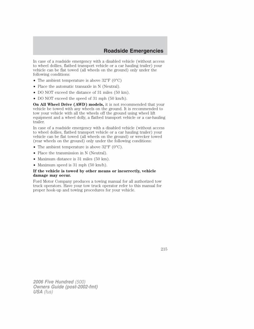
In case of a roadside emergency with a disabled vehicle (without accessto wheel dollies, flatbed transport vehicle or a car hauling trailer) yourvehicle can be flat towed (all wheels on the ground) only under thefollowing conditions:
• The ambient temperature is above 32°F (0°C)
• Place the automatic transaxle in N (Neutral).
• DO NOT exceed the distance of 31 miles (50 km).
• DO NOT exceed the speed of 31 mph (50 km/h).
On All Wheel Drive (AWD) models, it is not recommended that yourvehicle be towed with any wheels on the ground. It is recommended totow your vehicle with all the wheels off the ground using wheel liftequipment and a wheel dolly, a flatbed transport vehicle or a car-haulingtrailer.
In case of a roadside emergency with a disabled vehicle (without accessto wheel dollies, flatbed transport vehicle or a car hauling trailer) yourvehicle can be flat towed (all wheels on the ground) or wrecker towed(rear wheels on the ground) only under the following conditions:
• The ambient temperature is above 32°F (0°C).
• Place the transmission in N (Neutral).
• Maximum distance is 31 miles (50 km).
• Maximum speed is 31 mph (50 km/h).
If the vehicle is towed by other means or incorrectly, vehicledamage may occur.
Ford Motor Company produces a towing manual for all authorized towtruck operators. Have your tow truck operator refer to this manual forproper hook-up and towing procedures for your vehicle.
2006 Five Hundred (500)Owners Guide (post-2002-fmt)USA (fus)
Roadside Emergencies
215
GETTING THE SERVICES YOU NEED
At homeYou must take your Ford vehicle to an authorized dealer for warrantyrepairs. While any authorized dealer handling your vehicle line willprovide warranty service, we recommend you return to your sellingauthorized dealer who wants to ensure your continued satisfaction.Please note that certain warranty repairs require special training and/orequipment, so not all authorized dealers are authorized to perform allwarranty repairs. This means that, depending on the warranty repairneeded, you may have to take your vehicle to another authorized dealer.A reasonable time must be allowed to perform a repair after taking yourvehicle to the authorized dealer. Repairs will be made using Ford orMotorcraft parts, or remanufactured or other parts that are authorized byFord.
If you have questions or concerns, or are unsatisfied with the service youare receiving, follow these steps:
1. Contact your Sales Representative or Service Advisor at yourselling/servicing authorized dealer.
2. If your inquiry or concern remains unresolved, contact the SalesManager, Service Manager or Customer Relations Manager.
3. If you require assistance or clarification on Ford Motor Companypolicies or procedures, please contact the Ford Customer RelationshipCenter at 1-800-392-3673 (FORD).
Away from homeIf you own a Ford or Mercury vehicle and are away from home whenyour vehicle needs service, or if you need more help than the authorizeddealer could provide, after following the steps described above, contactthe Ford Customer Relationship Center to find an authorized dealer tohelp you.
In the United States:
Ford Motor CompanyCustomer Relationship CenterP.O. Box 6248Dearborn, MI 481211-800-392-3673 (FORD)(TDD for the hearing impaired: 1-800-232-5952)www.customersaskford.com
2006 Five Hundred (500)Owners Guide (post-2002-fmt)USA (fus)
Customer Assistance
216
In Canada:Customer Relationship CentreFord Motor Company of Canada, LimitedP.O. Box 2000Oakville, Ontario L6J 5E41-800-565-3673 (FORD)www.ford.caIf you own a Lincoln vehicle and are away from home when your vehicleneeds service, or if you need more help than the authorized dealer couldprovide, after following the steps described above, contact the FordCustomer Relationship Center to find an authorized dealer to help you.In the United States:Ford Motor CompanyCustomer Relationship CenterP.O. Box 6248Dearborn, MI 481211-800-521-4140(TDD for the hearing impaired: 1-800-232-5952)www.customersaskford.comIn Canada:Lincoln CentreFord Motor Company of Canada, LimitedP.O. Box 2000Oakville, Ontario L6J 5E41-800-387-9333www.lincolncanada.com
In order to help you service your Lincoln vehicle, please have thefollowing information available when contacting the Lincoln Centre:
• Your telephone number (home and business)
• The name of the authorized dealer and the city where the authorizeddealer is located
• The year and make of your vehicle
• The date of vehicle purchase
• The current odometer reading
• The vehicle identification number (VIN)
Additional AssistanceIf you still have a complaint involving a warranty dispute, you may wishto contact the Better Business Bureau (BBB) AUTO LINE program (U.S.only).
2006 Five Hundred (500)Owners Guide (post-2002-fmt)USA (fus)
Customer Assistance
217
In some states (in the U.S.) you must directly notify Ford in writingbefore pursuing remedies under your state’s warranty laws. Ford is alsoallowed a final repair attempt in some states.In the United States, a warranty dispute must be submitted to the BBBAUTO LINE before taking action under the Magnuson-Moss WarrantyAct, or to the extent allowed by state law, before pursuing replacementor repurchase remedies provided by certain state laws. This disputehandling procedure is not required prior to enforcing state created rightsor other rights which are independent of the Magnuson-Moss WarrantyAct or state replacement or repurchase laws.
IN CALIFORNIA (U.S. ONLY)California Civil Code Section 1793.2(d) requires that, if a manufactureror its representative is unable to repair a motor vehicle to conform to thevehicle’s applicable express warranty after a reasonable number ofattempts, the manufacturer shall be required to either replace thevehicle with one substantially identical or repurchase the vehicle andreimburse the buyer in an amount equal to the actual price paid orpayable by the consumer (less a reasonable allowance for consumeruse). The consumer has the right to choose whether to receive a refundor replacement vehicle.
California Civil Code Section 1793.22(b) presumes that the manufacturerhas had a reasonable number of attempts to conform the vehicle to itsapplicable express warranties if, within the first 18 months of ownershipof a new vehicle or the first 18,000 miles (29,000 km), whichever occursfirst:
1. Two or more repair attempts are made on the same non-conformitylikely to cause death or serious bodily injury OR
2. Four or more repair attempts are made on the same nonconformity (adefect or condition that substantially impairs the use, value or safety ofthe vehicle) OR
3. The vehicle is out of service for repair of nonconformities for a total ofmore than 30 calendar days (not necessarily all at one time)
In the case of 1 or 2 above, the consumer must also notify themanufacturer of the need for the repair of the nonconformity at thefollowing address:
Ford Motor Company16800 Executive Plaza DriveMail Drop 3NE-BDearborn, MI 48126
2006 Five Hundred (500)Owners Guide (post-2002-fmt)USA (fus)
Customer Assistance
218
THE BETTER BUSINESS BUREAU (BBB) AUTO LINE PROGRAM(U.S. ONLY)Your satisfaction is important to Ford Motor Company and to your dealer.Experience has shown that our customers have been very successful inachieving satisfaction by following the three-step procedure outlined onthe front page of the Warranty Guide. However, if your warranty concernhas not been resolved using the three-step procedure, you may beeligible to participate in the BBB AUTO LINE program.
The BBB AUTO LINE program consists of two parts – mediation andarbitration. Initially, the BBB will try to resolve your question or concernthrough mediation. Mediation is a process through which arepresentative of the BBB will contact the parties and explore optionsfor settlement of your claim. If mediation is not successful, customerswith eligible claims may participate in the BBB AUTO LINE arbitrationprocess. An arbitration hearing will be scheduled so that you can presentyour case in an informal setting before an impartial person. Thearbitrator will consider the testimony provided and make a decision afterthe hearing. You are not bound by the decision but may choose to acceptit. If you choose to accept the BBB AUTO LINE decision then Ford mustabide by the accepted decision as well. If the arbitrator has decided inyour favor and you accept the decision, the BBB AUTO LINE programwill contact you to ensure that Ford has complied with the decision in atimely manner. Disputes submitted to the BBB AUTO LINE program areusually decided within forty days after you file your claim with the BBB.
To file a claim with the BBB AUTO LINE, you will be asked for yourname and address, information about your vehicle, information aboutyour concerns and any steps you have already taken to try to resolvethem.
You can get more information by calling BBB AUTO LINE at1–800–955–5100, or writing to:
BBB AUTO LINE4200 Wilson Boulevard, Suite 800Arlington, Virginia 22203–1833
Note: Ford Motor Company reserves the right to change eligibilitylimitations, modify procedures, or to discontinue this process at any timewithout notice and without obligation.
2006 Five Hundred (500)Owners Guide (post-2002-fmt)USA (fus)
Customer Assistance
219
UTILIZING THE MEDIATION/ARBITRATION PROGRAM(CANADA ONLY)For vehicles delivered to authorized Canadian dealers. In those caseswhere you continue to feel that the efforts by Ford of Canada and theauthorized dealer to resolve a factory-related vehicle service concernhave been unsatisfactory, Ford of Canada participates in an impartialthird party mediation/arbitration program administered by the CanadianMotor Vehicle Arbitration Plan (CAMVAP).
The CAMVAP program is a straight-forward and relatively speedyalternative to resolve a disagreement when all other efforts to produce asettlement have failed. This procedure is without cost to you and isdesigned to eliminate the need for lengthy and expensive legalproceedings.
In the CAMVAP program, impartial third-party arbitrators conducthearings at mutually convenient times and places in an informalenvironment. These impartial arbitrators review the positions of theparties, make decisions and, when appropriate, render awards to resolvedisputes. CAMVAP decisions are fast, fair, and final as the arbitrator’saward is binding both to you and Ford of Canada.
CAMVAP services are available in all territories and provinces. For moreinformation, without charge or obligation, call your CAMVAP ProvincialAdministrator directly at 1-800-207-0685.
FORD EXTENDED SERVICE PLANYou can get more protection for your new car or light truck bypurchasing Ford Extended Service Plan (Ford ESP) coverage. It providesthe following:
• Benefits during the warranty period depending on the plan youpurchase (such as: reimbursement for rentals; coverage for certainmaintenance and wear items).
• Protection against covered repair costs after your Bumper-to-BumperWarranty expires.
You may purchase Ford ESP from any participating authorized dealer.There are several plans available in various time, distance and deductiblecombinations which can be tailored to fit your own driving needs. FordESP also offers reimbursement benefits for towing and rental coverage.
When you buy Ford ESP, you receive Peace-of-Mind protectionthroughout the United States and Canada, provided by a network ofmore than 4,600 participating authorized dealers.
2006 Five Hundred (500)Owners Guide (post-2002-fmt)USA (fus)
Customer Assistance
220
If you did not take advantage of the Ford Extended Service Plan at thetime of purchasing your vehicle, you may still be eligible. Since thisinformation is subject to change, please ask your authorized dealer forcomplete details about Ford Extended Service Plan coverage options, orvisit the Ford ESP website at www.ford-esp.com.
GETTING ASSISTANCE OUTSIDE THE U.S. AND CANADABefore exporting your vehicle to a foreign country, contact theappropriate foreign embassy or consulate. These officials can inform youof local vehicle registration regulations and where to find unleaded fuel.
If you cannot find unleaded fuel or can only get fuel with an anti-knockindex lower than is recommended for your vehicle, contact a regionaloffice or owner relations/customer relationship office.
The use of leaded fuel in your vehicle without proper conversion maydamage the effectiveness of your emission control system and may causeengine knocking or serious engine damage. Ford Motor Company/Ford ofCanada is not responsible for any damage caused by use of improperfuel. Using leaded fuel may also result in difficulty importing your vehicleback into the U.S.
If your vehicle must be serviced while you are traveling or living inCentral America, the Caribbean, or the Middle East, contact the nearestauthorized dealer. If the authorized dealer cannot help you, write or call:
FORD MOTOR COMPANYWORLDWIDE DIRECT MARKET OPERATIONS1555 Fairlane DriveFairlane Business Park #3Allen Park, Michigan 48101U.S.A.Telephone: (313) 594-4857FAX: (313) 390-0804
If you are in another foreign country, contact the nearest authorizeddealer. If the authorized dealer employees cannot help you, they candirect you to the nearest Ford affiliate office.
If you buy your vehicle in North America and then relocate outside ofthe U.S. or Canada, register your vehicle identification number (VIN) andnew address with Ford Motor Company Worldwide Direct MarketOperations.
Customers in the U.S. should call 1–800–392–3673.
2006 Five Hundred (500)Owners Guide (post-2002-fmt)USA (fus)
Customer Assistance
221
ORDERING ADDITIONAL OWNER’S LITERATURETo order the publications in this portfolio, contact Helm, Incorporated at:HELM, INCORPORATEDP.O. Box 07150Detroit, Michigan 48207Or call:For a free publication catalog, order toll free: 1-800-782-4356
Monday-Friday 8:00 a.m. - 6:00 p.m. EST
Helm, Incorporated can also be reached by their website:www.helminc.com.
(Items in this catalog may be purchased by credit card, check ormoney order.)
Obtaining a French owner’s guideFrench Owner’s Guides can be obtained from your authorized dealer orby writing to Ford Motor Company of Canada, Limited, ServicePublications, P.O. Box 1580, Station B, Mississauga, Ontario L4Y 4G3.
REPORTING SAFETY DEFECTS (U.S. ONLY)If you believe that your vehicle hasa defect which could cause a crashor could cause injury or death, youshould immediately inform theNational Highway Traffic SafetyAdministration (NHTSA) in addition to notifying Ford Motor Company.
If NHTSA receives similar complaints, it may open an investigation, and if itfinds that a safety defect exists in a group of vehicles, it may order a recalland remedy campaign. However, NHTSA cannot become involved inindividual problems between you, your dealer, or Ford Motor Company.
To contact NHTSA, you may call the Vehicle Safety Hotline toll-free at1–888–327–4236 (TTY: 1–800–424–9153); go to http://www.safercar.gov;or write to:
AdministratorNHTSA400 Seventh Street, SWWashington, D.C. 20590
You can also obtain other information about motor vehicle safety fromhttp://www.safercar.gov.
2006 Five Hundred (500)Owners Guide (post-2002-fmt)USA (fus)
Customer Assistance
222
WASHING THE EXTERIORWash your vehicle regularly with cool or lukewarm water and a neutralpH shampoo, such as Motorcraft Detail Wash (ZC-3–A), which isavailable from your authorized dealer.
• Never use strong household detergents or soap, such as dish washingor laundry liquid. These products can discolor and spot paintedsurfaces.
• Never wash a vehicle that is “hot to the touch” or during exposure tostrong, direct sunlight.
• Always use a clean sponge or car wash mitt with plenty of water forbest results.
• Dry the vehicle with a chamois or soft terry cloth towel in order toeliminate water spotting.
• It is especially important to wash the vehicle regularly during thewinter months, as dirt and road salt are difficult to remove and causedamage to the vehicle.
• Immediately remove items such as gasoline, diesel fuel, bird droppingsand insect deposits because they can cause damage to the vehicle’spaintwork and trim over time.
• Remove any exterior accessories, such as antennas, before entering acar wash.
• Suntan lotions and insect repellents can damage any paintedsurface; if these substances come in contact with your vehicle,wash off as soon as possible.
Exterior chrome
• Wash the vehicle first, using cool or lukewarm water and a neutral pHshampoo, such as Motorcraft Detail Wash (ZC-3–A).
• Use Custom Brite Metal Cleaner (ZC-15), available from yourauthorized dealer. Apply the product as you would a wax to cleanbumpers and other chrome parts; allow the cleaner to dry for a fewminutes, then wipe off the haze with a clean, dry rag.
• Never use abrasive materials such as steel wool or plastic padsas they can scratch the chrome surface.
2006 Five Hundred (500)Owners Guide (post-2002-fmt)USA (fus)
Cleaning
223
WAXINGApplying Motorcraft Paint Sealant (ZC-45) to your vehicle every sixmonths will assist in reducing minor scratches and paint damage.
• Wash the vehicle first.
• Do not use waxes that contain abrasives; use Motorcraft PremiumLiquid Wax (ZC-53-A), which is available from your authorized dealer,or an equivalent quality product.
• Do not allow paint sealant to come in contact with any non-body(low-gloss black) colored trim, such as grained door handles, roofracks, bumpers, side moldings, mirror housings or the windshield cowlarea. The paint sealant will “gray” or stain the parts over time.
PAINT CHIPSYour authorized dealer has touch-up paint and sprays to match yourvehicle’s color. Take your color code (printed on a sticker in the driver’sdoor jamb) to your authorized dealer to ensure you get the correct color.
• Remove particles such as bird droppings, tree sap, insect deposits, tarspots, road salt and industrial fallout before repairing paint chips.
• Always read the instructions before using the products.
ALUMINUM WHEELS AND WHEEL COVERSAluminum wheels and wheel covers are coated with a clearcoat paintfinish. In order to maintain their shine:
• Clean weekly with Motorcraft Wheel and Tire Cleaner (ZC-37–A),which is available from your authorized dealer. Heavy dirt and brakedust accumulation may require agitation with a sponge. Rinsethoroughly with a strong stream of water.
• Never apply any cleaning chemical to hot or warm wheel rims orcovers.
• Some automatic car washes may cause damage to the finish on yourwheel rims or covers. Chemical-strength cleaners, or cleaningchemicals, in combination with brush agitation to remove brake dustand dirt, could wear away the clearcoat finish over time.
• Do not use hydrofluoric acid-based or high caustic-based wheelcleaners, steel wool, fuels or strong household detergent.
• To remove tar and grease, use Motorcraft Bug and Tar Remover(ZC-42), available from your authorized dealer.
2006 Five Hundred (500)Owners Guide (post-2002-fmt)USA (fus)
Cleaning
224
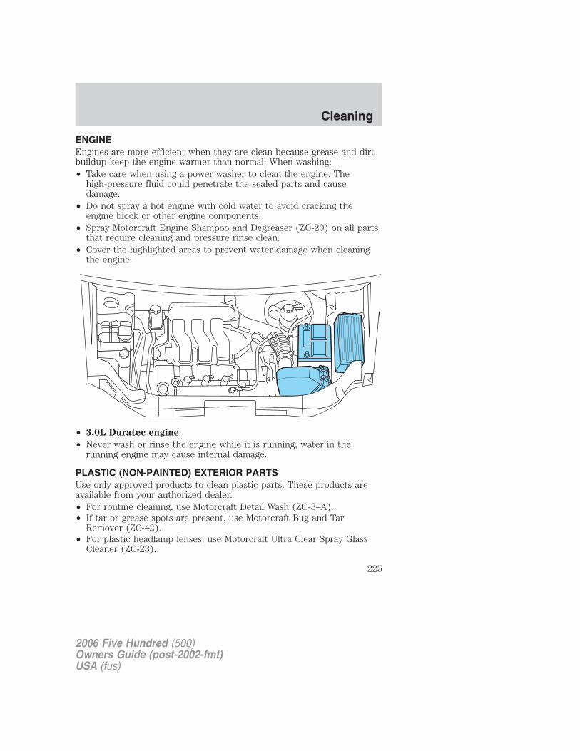
ENGINEEngines are more efficient when they are clean because grease and dirtbuildup keep the engine warmer than normal. When washing:• Take care when using a power washer to clean the engine. The
high-pressure fluid could penetrate the sealed parts and causedamage.
• Do not spray a hot engine with cold water to avoid cracking theengine block or other engine components.
• Spray Motorcraft Engine Shampoo and Degreaser (ZC-20) on all partsthat require cleaning and pressure rinse clean.
• Cover the highlighted areas to prevent water damage when cleaningthe engine.
• 3.0L Duratec engine
• Never wash or rinse the engine while it is running; water in therunning engine may cause internal damage.
PLASTIC (NON-PAINTED) EXTERIOR PARTSUse only approved products to clean plastic parts. These products areavailable from your authorized dealer.• For routine cleaning, use Motorcraft Detail Wash (ZC-3–A).• If tar or grease spots are present, use Motorcraft Bug and Tar
Remover (ZC-42).• For plastic headlamp lenses, use Motorcraft Ultra Clear Spray Glass
Cleaner (ZC-23).
2006 Five Hundred (500)Owners Guide (post-2002-fmt)USA (fus)
Cleaning
225
WINDOWS AND WIPER BLADES
The windshield, rear and side windows and the wiper blades should becleaned regularly. If the wipers do not wipe properly, substances on thevehicle’s glass or the wiper blades may be the cause. These may includehot wax treatments used by commercial car washes, water repellantcoatings, tree sap, or other organic contamination; these contaminantsmay cause squeaking or chatter noise from the blades, and streaking andsmearing of the windshield. To clean these items, follow these tips:
• The windshield, rear windows and side windows may be cleaned witha non-abrasive cleaner such as Motorcraft Ultra-Clear Spray GlassCleaner (ZC-23), available from your authorized dealer.
• The wiper blades can be cleaned with isopropyl (rubbing) alcohol orMotorcraft Premium Windshield Washer Concentrate (ZC-32–A),available from your authorized dealer. This washer fluid containsspecial solution in addition to alcohol which helps to remove the hotwax deposited on the wiper blade and windshield from automated carwash facilities. Be sure to replace wiper blades when they appearworn or do not function properly.
• Do not use abrasives, as they may cause scratches.
• Do not use fuel, kerosene, or paint thinner to clean any parts.
If you cannot remove those streaks after cleaning with the glass cleaneror if the wipers chatter and move in a jerky motion, clean the outersurface of the windshield and the wiper blades using a sponge or softcloth with a neutral detergent or mild-abrasive cleaning solution. Aftercleaning, rinse the windshield and wiper blades with clean water. Thewindshield is clean if beads do not form when you rinse the windshieldwith water.
Do not use sharp objects, such as a razor blade, to clean theinside of the rear window or to remove decals, as it may causedamage to the rear window defroster’s heated grid lines.
INSTRUMENT PANEL AND CLUSTER LENSClean the instrument panel with a damp cloth, then with a clean, drycloth, or use Motorcraft Dash & Vinyl Cleaner (ZC-38-A).
• Avoid cleaners or polish that increase the gloss of the upper portion ofthe instrument panel. The dull finish in this area helps protect thedriver from undesirable windshield reflection.
2006 Five Hundred (500)Owners Guide (post-2002-fmt)USA (fus)
Cleaning
226
Do not use chemical solvents or strong detergents when cleaningthe steering wheel or instrument panel to avoid contamination of
the airbag system.
• Be certain to wash or wipe your hands clean if you have been incontact with certain products such as insect repellent and suntanlotion in order to avoid possible damage to the interior paintedsurfaces.
INTERIOR TRIM• Clean the interior trim areas with a damp cloth, then with a clean, dry
cloth; you may also use Motorcraft Dash & Vinyl Cleaner (ZC-38-A).
• Do not use household or glass cleaners as these may damage thefinish.
INTERIORFor fabric, carpets, cloth seats, safety belts and seats equipped with sideairbags:
• Remove dust and loose dirt with a vacuum cleaner.
• Remove light stains and soil with Motorcraft Professional StrengthCarpet & Upholstery Cleaner (ZC-54).
• If grease or tar is present on the material, spot-clean the area firstwith Motorcraft Spot and Stain Remover (ZC-14).
• If a ring forms on the fabric after spot cleaning, clean the entire areaimmediately (but do not oversaturate) or the ring will set.
• Do not use household cleaning products or glass cleaners, which canstain and discolor the fabric and affect the flame retardant abilities ofthe seat materials.
Do not use cleaning solvents, bleach or dye on the vehicle’ssafety belts, as these actions may weaken the belt webbing.
Do not use chemical solvents or strong detergents when cleaningthe seat-mounted side airbag (if equipped). Such products could
contaminate the side airbag system and affect performance of the sideairbag in a collision.
2006 Five Hundred (500)Owners Guide (post-2002-fmt)USA (fus)
Cleaning
227
LEATHER SEATS (IF EQUIPPED)Your leather seating surfaces have a clear, protective coating over theleather.• To clean, use a soft cloth with Motorcraft Deluxe Leather and Vinyl
Cleaner (ZC-11–A). Dry the area with a soft cloth.• To help maintain its resiliency and color, use the Motorcraft Deluxe
Leather Care Kit (ZC-11–D), available from your authorized dealer.• Do not use household cleaning products, alcohol solutions, solvents or
cleaners intended for rubber, vinyl and plastics, or oil/petroleum-basedleather conditioners. These products may cause premature wearing ofthe clear, protective coating.
Note: In some instances, color or dye transfer can occur when wetclothing comes in contact with leather upholstery. If this occurs, theleather should be cleaned immediately to avoid permanent staining.
UNDERBODYFlush the complete underside of your vehicle frequently. Keep body anddoor drain holes free from packed dirt.
FORD AND LINCOLN MERCURY CAR CARE PRODUCTSYour Ford or Lincoln Mercury authorized dealer has many qualityproducts available to clean your vehicle and protect its finishes. Thesequality products have been specifically engineered to fulfill yourautomotive needs; they are custom designed to complement the styleand appearance of your vehicle. Each product is made from high qualitymaterials that meet or exceed rigid specifications. For best results, usethe following products or products of equivalent quality:
Motorcraft Bug and Tar Remover (ZC-42)
Motorcraft Car Care Kit (ZC-26)
Motorcraft Car Wash (Canada only) (CXC-21)
Motorcraft Custom Bright Metal Cleaner (ZC-15)
Motorcraft Custom Clear Coat Polish (ZC–8–A)
Motorcraft Custom Vinyl Protectant (U.S. only) (ZC-40-A)
Motorcraft Dash and Vinyl Cleaner (ZC-38–A)
Motorcraft Deluxe Leather and Vinyl Cleaner (U.S. only) (ZC-11–A)
Motorcraft Detail Wash (ZC-3–A)
Motorcraft Dusting Cloth (ZC-24)
2006 Five Hundred (500)Owners Guide (post-2002-fmt)USA (fus)
Cleaning
228
Motorcraft Engine Shampoo and Degreaser (U.S. only) (ZC-20)
Motorcraft Engine Shampoo (Canada only) (CXC-66-A)
Motorcraft One Step Wash and Wax Concentrate (ZC-6-A)
Motorcraft Paint Sealant (ZC-45)
Motorcraft Premium Car Wash Concentrate (U.S. only) (ZC-17-B)
Motorcraft Premium Glass Cleaner (Canada only) (CXC-100)
Motorcraft Premium Liquid Wax (ZC-53-A)
Motorcraft Premium Windshield Washer Concentrate (ZC-32–A)
Motorcraft Professional Strength Carpet & Upholstery Cleaner (ZC-54)
Motorcraft Spot and Stain Remover (U.S. only) (ZC-14)
Motorcraft Tire Clean and Shine (ZC-28)
Motorcraft Triple Clean (U.S. only) (ZC-13)
Motorcraft Ultra-Clear Spray Glass Cleaner (ZC-23)
Motorcraft Vinyl Cleaner (Canada only) (CXC-93)
Motorcraft Vinyl Conditioner (Canada only) (CXC-94)
Motorcraft Wheel and Tire Cleaner (ZC-37–A)
2006 Five Hundred (500)Owners Guide (post-2002-fmt)USA (fus)
Cleaning
229
SERVICE RECOMMENDATIONS
To help you service your vehicle we provide scheduled maintenanceinformation which makes tracking routine service easy.
If your vehicle requires professional service, your authorized dealer canprovide the necessary parts and service. Check your WarrantyGuide/Owner Information Guide to find out which parts and servicesare covered.
Use only recommended fuels, lubricants, fluids and service partsconforming to specifications. Motorcraft parts are designed and built toprovide the best performance in your vehicle.
PRECAUTIONS WHEN SERVICING YOUR VEHICLE
• Do not work on a hot engine.
• Make sure that nothing gets caught in moving parts.
• Do not work on a vehicle with the engine running in an enclosedspace, unless you are sure you have enough ventilation.
• Keep all open flames and other burning (cigarettes) material awayfrom the battery and all fuel related parts.
Working with the engine off
1. Set the parking brake and shift to P (Park).
2. Turn off the engine and remove the key.
3. Block the wheels.
Working with the engine on
1. Set the parking brake and ensure the gearshift is securely latched in P(Park).
2. Block the wheels to prevent the vehicle from moving unexpectedly.
To reduce the risk of vehicle damage and/or personal burninjuries do not start your engine with the air cleaner removed
and do not remove it while the engine is running.
2006 Five Hundred (500)Owners Guide (post-2002-fmt)USA (fus)
Maintenance and Specifications
230
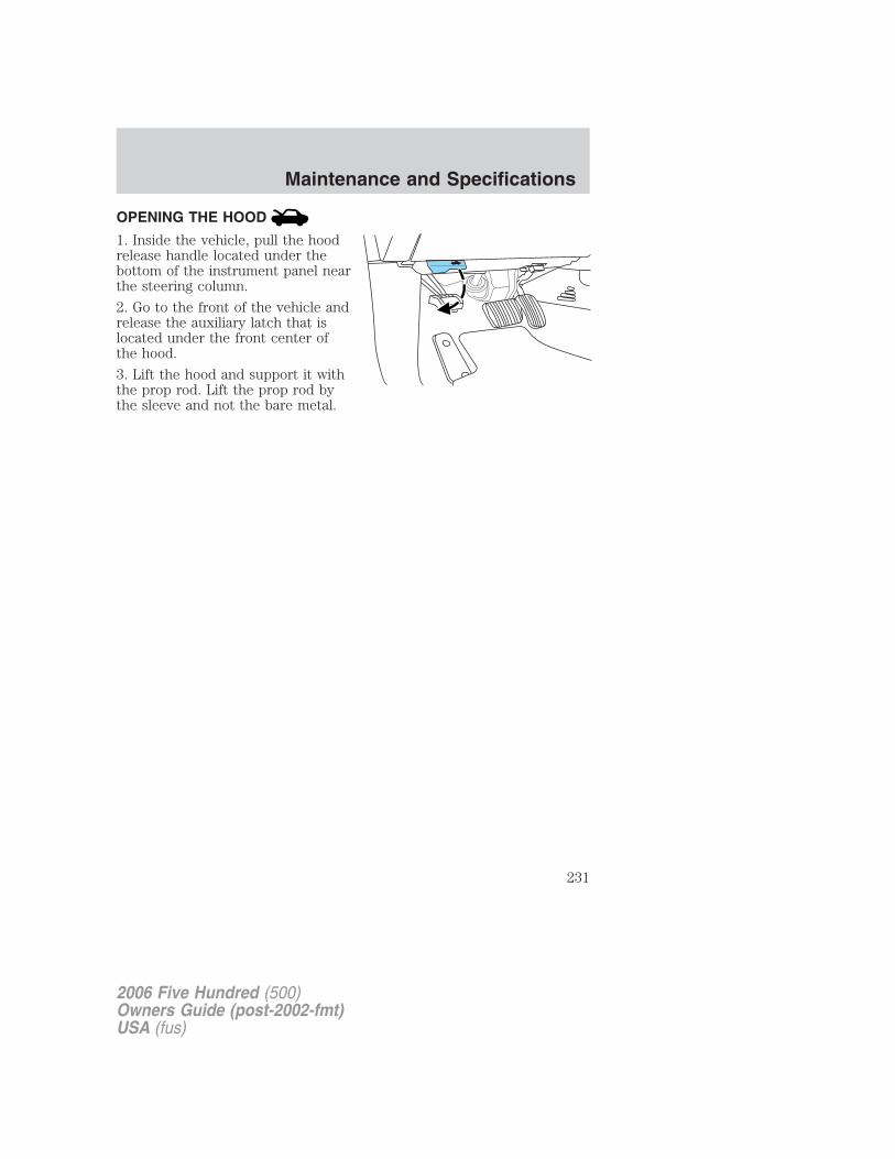
OPENING THE HOOD
1. Inside the vehicle, pull the hoodrelease handle located under thebottom of the instrument panel nearthe steering column.
2. Go to the front of the vehicle andrelease the auxiliary latch that islocated under the front center ofthe hood.
3. Lift the hood and support it withthe prop rod. Lift the prop rod bythe sleeve and not the bare metal.
2006 Five Hundred (500)Owners Guide (post-2002-fmt)USA (fus)
Maintenance and Specifications
231
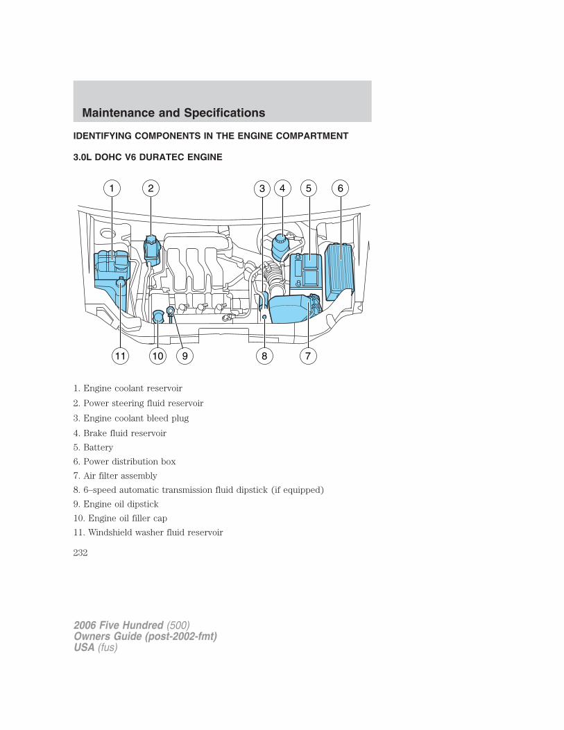
IDENTIFYING COMPONENTS IN THE ENGINE COMPARTMENT
3.0L DOHC V6 DURATEC ENGINE
1. Engine coolant reservoir
2. Power steering fluid reservoir
3. Engine coolant bleed plug
4. Brake fluid reservoir
5. Battery
6. Power distribution box
7. Air filter assembly
8. 6–speed automatic transmission fluid dipstick (if equipped)
9. Engine oil dipstick
10. Engine oil filler cap
11. Windshield washer fluid reservoir
2006 Five Hundred (500)Owners Guide (post-2002-fmt)USA (fus)
Maintenance and Specifications
232
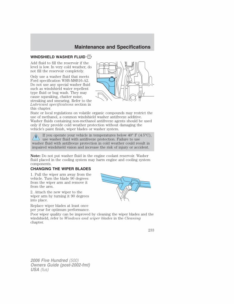
WINDSHIELD WASHER FLUID
Add fluid to fill the reservoir if thelevel is low. In very cold weather, donot fill the reservoir completely.
Only use a washer fluid that meetsFord specification WSB-M8B16-A2.Do not use any special washer fluidsuch as windshield water repellenttype fluid or bug wash. They maycause squeaking, chatter noise,streaking and smearing. Refer to theLubricant specifications section inthis chapter.State or local regulations on volatile organic compounds may restrict theuse of methanol, a common windshield washer antifreeze additive.Washer fluids containing non-methanol antifreeze agents should be usedonly if they provide cold weather protection without damaging thevehicle’s paint finish, wiper blades or washer system.
If you operate your vehicle in temperatures below 40° F (4.5°C),use washer fluid with antifreeze protection. Failure to use
washer fluid with antifreeze protection in cold weather could result inimpaired windshield vision and increase the risk of injury or accident.
Note: Do not put washer fluid in the engine coolant reservoir. Washerfluid placed in the cooling system may harm engine and cooling systemcomponents.CHANGING THE WIPER BLADES1. Pull the wiper arm away from thevehicle. Turn the blade 90 degreesfrom the wiper arm and remove itfrom the arm.
2. Attach the new wiper to thewiper arm by turning it 90 degreesinto place.
Replace wiper blades at least onceper year for optimum performance.Poor wiper quality can be improved by cleaning the wiper blades and thewindshield, refer to Windows and wiper blades in the Cleaningchapter.
2006 Five Hundred (500)Owners Guide (post-2002-fmt)USA (fus)
Maintenance and Specifications
233
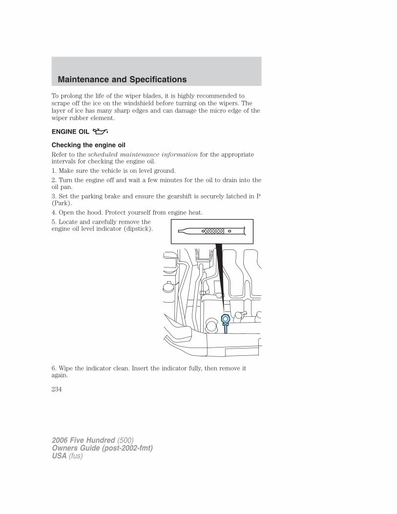
To prolong the life of the wiper blades, it is highly recommended toscrape off the ice on the windshield before turning on the wipers. Thelayer of ice has many sharp edges and can damage the micro edge of thewiper rubber element.
ENGINE OIL
Checking the engine oilRefer to the scheduled maintenance information for the appropriateintervals for checking the engine oil.
1. Make sure the vehicle is on level ground.
2. Turn the engine off and wait a few minutes for the oil to drain into theoil pan.
3. Set the parking brake and ensure the gearshift is securely latched in P(Park).
4. Open the hood. Protect yourself from engine heat.
5. Locate and carefully remove theengine oil level indicator (dipstick).
6. Wipe the indicator clean. Insert the indicator fully, then remove itagain.
2006 Five Hundred (500)Owners Guide (post-2002-fmt)USA (fus)
Maintenance and Specifications
234
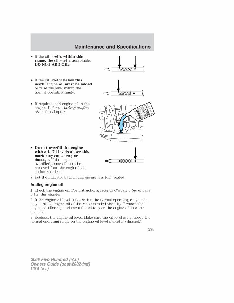
• If the oil level is within thisrange, the oil level is acceptable.DO NOT ADD OIL.
• If the oil level is below thismark, engine oil must be addedto raise the level within thenormal operating range.
• If required, add engine oil to theengine. Refer to Adding engineoil in this chapter.
• Do not overfill the enginewith oil. Oil levels above thismark may cause enginedamage. If the engine isoverfilled, some oil must beremoved from the engine by anauthorized dealer.
7. Put the indicator back in and ensure it is fully seated.
Adding engine oil1. Check the engine oil. For instructions, refer to Checking the engineoil in this chapter.
2. If the engine oil level is not within the normal operating range, addonly certified engine oil of the recommended viscosity. Remove theengine oil filler cap and use a funnel to pour the engine oil into theopening.
3. Recheck the engine oil level. Make sure the oil level is not above thenormal operating range on the engine oil level indicator (dipstick).
2006 Five Hundred (500)Owners Guide (post-2002-fmt)USA (fus)
Maintenance and Specifications
235
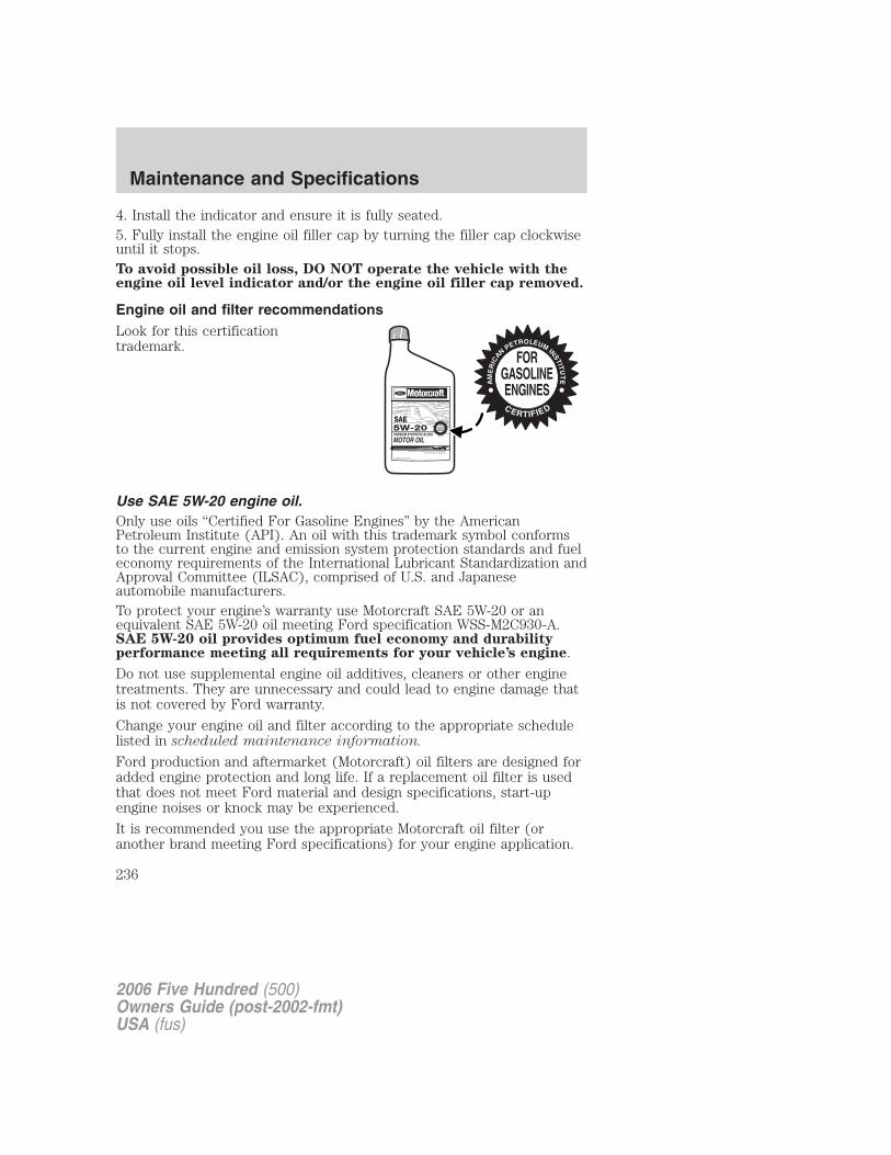
4. Install the indicator and ensure it is fully seated.5. Fully install the engine oil filler cap by turning the filler cap clockwiseuntil it stops.To avoid possible oil loss, DO NOT operate the vehicle with theengine oil level indicator and/or the engine oil filler cap removed.
Engine oil and filter recommendationsLook for this certificationtrademark.
Use SAE 5W-20 engine oil.Only use oils “Certified For Gasoline Engines” by the AmericanPetroleum Institute (API). An oil with this trademark symbol conformsto the current engine and emission system protection standards and fueleconomy requirements of the International Lubricant Standardization andApproval Committee (ILSAC), comprised of U.S. and Japaneseautomobile manufacturers.To protect your engine’s warranty use Motorcraft SAE 5W-20 or anequivalent SAE 5W-20 oil meeting Ford specification WSS-M2C930-A.SAE 5W-20 oil provides optimum fuel economy and durabilityperformance meeting all requirements for your vehicle’s engine.
Do not use supplemental engine oil additives, cleaners or other enginetreatments. They are unnecessary and could lead to engine damage thatis not covered by Ford warranty.
Change your engine oil and filter according to the appropriate schedulelisted in scheduled maintenance information.
Ford production and aftermarket (Motorcraft) oil filters are designed foradded engine protection and long life. If a replacement oil filter is usedthat does not meet Ford material and design specifications, start-upengine noises or knock may be experienced.
It is recommended you use the appropriate Motorcraft oil filter (oranother brand meeting Ford specifications) for your engine application.
2006 Five Hundred (500)Owners Guide (post-2002-fmt)USA (fus)
Maintenance and Specifications
236
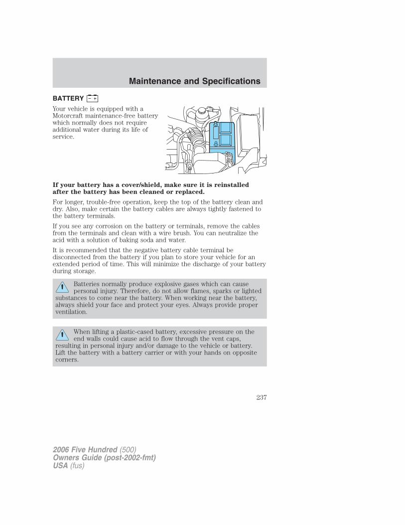
BATTERY
Your vehicle is equipped with aMotorcraft maintenance-free batterywhich normally does not requireadditional water during its life ofservice.
If your battery has a cover/shield, make sure it is reinstalledafter the battery has been cleaned or replaced.
For longer, trouble-free operation, keep the top of the battery clean anddry. Also, make certain the battery cables are always tightly fastened tothe battery terminals.
If you see any corrosion on the battery or terminals, remove the cablesfrom the terminals and clean with a wire brush. You can neutralize theacid with a solution of baking soda and water.
It is recommended that the negative battery cable terminal bedisconnected from the battery if you plan to store your vehicle for anextended period of time. This will minimize the discharge of your batteryduring storage.
Batteries normally produce explosive gases which can causepersonal injury. Therefore, do not allow flames, sparks or lighted
substances to come near the battery. When working near the battery,always shield your face and protect your eyes. Always provide properventilation.
When lifting a plastic-cased battery, excessive pressure on theend walls could cause acid to flow through the vent caps,
resulting in personal injury and/or damage to the vehicle or battery.Lift the battery with a battery carrier or with your hands on oppositecorners.
2006 Five Hundred (500)Owners Guide (post-2002-fmt)USA (fus)
Maintenance and Specifications
237
Keep batteries out of reach of children. Batteries contain sulfuricacid. Avoid contact with skin, eyes or clothing. Shield your eyes
when working near the battery to protect against possible splashing ofacid solution. In case of acid contact with skin or eyes, flushimmediately with water for a minimum of 15 minutes and get promptmedical attention. If acid is swallowed, call a physician immediately.
Battery posts, terminals and related accessories contain lead andlead compounds. Wash hands after handling.
Because your vehicle’s engine is electronically controlled by a computer,some control conditions are maintained by power from the battery. Whenthe battery is disconnected or a new battery is installed, the engine mustrelearn its idle and fuel trim strategy for optimum driveability andperformance. To begin this process:
1. With the vehicle at a complete stop, set the parking brake.
2. Put the gearshift in P (Park), turn off all accessories and start theengine.
3. Run the engine until it reaches normal operating temperature.
4. Allow the engine to idle for at least one minute.
5. Turn the A/C on and allow the engine to idle for at least one minute.
6. Release the parking brake. With your foot on the brake pedal and withthe A/C on, put the vehicle in D (Drive) and allow the engine to idle forat least one minute.
7. Drive the vehicle to complete the relearning process.
• The vehicle may need to be driven 10 miles (16 km) or more torelearn the idle and fuel trim strategy.
• If you do not allow the engine to relearn its idle trim, the idlequality of your vehicle may be adversely affected until the idletrim is eventually relearned.
If the battery has been disconnected or a new battery has been installed,the clock and radio settings must be reset once the battery isreconnected.
2006 Five Hundred (500)Owners Guide (post-2002-fmt)USA (fus)
Maintenance and Specifications
238
• Always dispose of automotivebatteries in a responsible manner.Follow your local authorizedstandards for disposal. Call yourlocal authorized recycling centerto find out more about recyclingautomotive batteries.
ENGINE COOLANT
Checking engine coolant
The concentration and level of engine coolant should be checked at theintervals listed in scheduled maintenance information. The coolantconcentration should be maintained at 50/50 coolant and distilled water,which equates to a freeze point of -34°F (-36°C). Coolant concentrationtesting is possible with a hydrometer or antifreeze tester (such as theRotunda Battery and Antifreeze Tester, 014–R1060). The level of coolantshould be maintained at the “FULL COLD” level or within the “COLDFILL RANGE” in the coolant reservoir. If the level falls below, addcoolant per the instructions in the Adding engine coolant section.
Your vehicle was factory-filled with a 50/50 engine coolant and waterconcentration. If the concentration of coolant falls below 40% or above60%, the engine parts could become damaged or not work properly. A50–50 mixture of coolant and water provides the following:
• Freeze protection down to -34°F (-36°C).
• Boiling protection up to 265°F (129°C).
• Protection against rust and other forms of corrosion.
• Enables calibrated gauges to work properly.
LE
AD
RE
TU
RN
RECYCLE
2006 Five Hundred (500)Owners Guide (post-2002-fmt)USA (fus)
Maintenance and Specifications
239
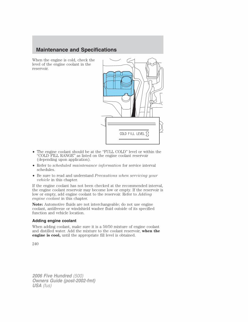
When the engine is cold, check thelevel of the engine coolant in thereservoir.
• The engine coolant should be at the “FULL COLD” level or within the“COLD FILL RANGE” as listed on the engine coolant reservoir(depending upon application).
• Refer to scheduled maintenance information for service intervalschedules.
• Be sure to read and understand Precautions when servicing yourvehicle in this chapter.
If the engine coolant has not been checked at the recommended interval,the engine coolant reservoir may become low or empty. If the reservoir islow or empty, add engine coolant to the reservoir. Refer to Addingengine coolant in this chapter.
Note: Automotive fluids are not interchangeable; do not use enginecoolant, antifreeze or windshield washer fluid outside of its specifiedfunction and vehicle location.
Adding engine coolantWhen adding coolant, make sure it is a 50/50 mixture of engine coolantand distilled water. Add the mixture to the coolant reservoir, when theengine is cool, until the appropriate fill level is obtained.
2006 Five Hundred (500)Owners Guide (post-2002-fmt)USA (fus)
Maintenance and Specifications
240
Do not add engine coolant when the engine is hot. Steam andscalding liquids released from a hot cooling system can burn you
badly. Also, you can be burned if you spill coolant on hot engine parts.
Do not put engine coolant in the windshield washer fluidcontainer. If sprayed on the windshield, engine coolant could
make it difficult to see through the windshield.
• Add Motorcraft Premium Gold Engine Coolant or equivalentmeeting Ford specification WSS-M97B51-A1. Refer to Lubricantspecifications in this chapter.
Note: Use of Motorcraft Cooling System Stop Leak Pellets or anequivalent product meeting Ford specification WSS-M99B37-B6, maydarken the color of Motorcraft Premium Gold Engine Coolant fromyellow to golden tan.• Do not add/mix an orange-colored, extended life coolant such
as Motorcraft Specialty Orange Engine Coolant, meeting Fordspecification WSS-M97B44-D, with the factory-filled coolant.Mixing Motorcraft Specialty Orange Engine Coolant or anyorange-colored extended life product with your factory filled coolantcan result in degraded corrosion protection.
• A large amount of water without engine coolant may be added, in caseof emergency, to reach a vehicle service location. In this instance, thecooling system must be drained and refilled with a 50/50 mixture ofengine coolant and distilled water as soon as possible. Water alone(without engine coolant) can cause engine damage from corrosion,overheating or freezing.
• Do not use alcohol, methanol, brine or any engine coolantsmixed with alcohol or methanol antifreeze (coolant). Alcoholand other liquids can cause engine damage from overheating orfreezing.
• Do not add extra inhibitors or additives to the coolant. Thesecan be harmful and compromise the corrosion protection of the enginecoolant.
To reduce the risk of personal injury, make sure the engine iscool before unscrewing the coolant pressure relief cap. The
cooling system is under pressure; steam and hot liquid can come outforcefully when the cap is loosened slightly.
2006 Five Hundred (500)Owners Guide (post-2002-fmt)USA (fus)
Maintenance and Specifications
241
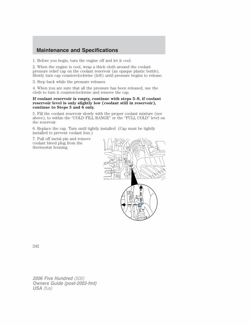
1. Before you begin, turn the engine off and let it cool.
2. When the engine is cool, wrap a thick cloth around the coolantpressure relief cap on the coolant reservoir (an opaque plastic bottle).Slowly turn cap counterclockwise (left) until pressure begins to release.
3. Step back while the pressure releases.
4. When you are sure that all the pressure has been released, use thecloth to turn it counterclockwise and remove the cap.
If coolant reservoir is empty, continue with steps 5–9, if coolantreservoir level is only slightly low (coolant still in reservoir),continue to Steps 5 and 6 only.
5. Fill the coolant reservoir slowly with the proper coolant mixture (seeabove), to within the “COLD FILL RANGE” or the “FULL COLD” level onthe reservoir.
6. Replace the cap. Turn until tightly installed. (Cap must be tightlyinstalled to prevent coolant loss.)
7. Pull off metal pin and removecoolant bleed plug from thethermostat housing.
2006 Five Hundred (500)Owners Guide (post-2002-fmt)USA (fus)
Maintenance and Specifications
242
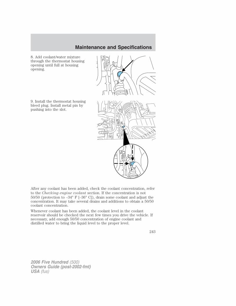
8. Add coolant/water mixturethrough the thermostat housingopening until full at housingopening.
9. Install the thermostat housingbleed plug. Install metal pin bypushing into the slot.
After any coolant has been added, check the coolant concentration, referto the Checking engine coolant section. If the concentration is not50/50 (protection to –34° F [–36° C]), drain some coolant and adjust theconcentration. It may take several drains and additions to obtain a 50/50coolant concentration.
Whenever coolant has been added, the coolant level in the coolantreservoir should be checked the next few times you drive the vehicle. Ifnecessary, add enough 50/50 concentration of engine coolant anddistilled water to bring the liquid level to the proper level.
2006 Five Hundred (500)Owners Guide (post-2002-fmt)USA (fus)
Maintenance and Specifications
243
If you have to add more than 1.0 quart (1.0 liter) of engine coolant permonth, have your authorized dealer check the engine cooling system.Your cooling system may have a leak. Operating an engine with a lowlevel of coolant can result in engine overheating and possible enginedamage.
Recycled engine coolantFord Motor Company does NOT recommend the use of recycled enginecoolant in vehicles originally equipped with Motorcraft Premium GoldEngine Coolant since a Ford-approved recycling process is not yetavailable.
Used engine coolant should be disposed of in an appropriatemanner. Follow your community’s regulations and standards for recyclingand disposing of automotive fluids.
Coolant refill capacityTo find out how much fluid your vehicle’s cooling system can hold, referto Refill capacities in this chapter.Fill your engine coolant reservoir as outlined in Adding engine coolantin this section.
Severe climatesIf you drive in extremely cold climates (less than –34° F [–36° C ]):• It may be necessary to increase the coolant concentration
above 50%.
• NEVER increase the coolant concentration above 60%.
• Increased engine coolant concentrations above 60% willdecrease the overheat protection characteristics of the enginecoolant and may cause engine damage.
• Refer to the chart on the coolant container to ensure thecoolant concentration in your vehicle will provide adequatefreeze protection at the temperatures in which you drive in thewinter months.
If you drive in extremely hot climates:• It is still necessary to maintain the coolant concentration
above 40%.
• NEVER decrease the coolant concentration below 40%.
• Decreased engine coolant concentrations below 40% willdecrease the corrosion protection characteristics of the enginecoolant and may cause engine damage.
2006 Five Hundred (500)Owners Guide (post-2002-fmt)USA (fus)
Maintenance and Specifications
244
• Decreased engine coolant concentrations below 40% willdecrease the freeze protection characteristics of the enginecoolant and may cause engine damage.
• Refer to the chart on the coolant container to ensure thecoolant concentration in your vehicle will provide adequateprotection at the temperatures in which you drive.
Vehicles driven year-round in non-extreme climates should use a 50/50mixture of engine coolant and distilled water for optimum cooling systemand engine protection.
FUEL FILTERFor fuel filter replacement, see your authorized dealer. Refer toscheduled maintenance information for the appropriate intervals forchanging the fuel filter.Replace the fuel filter with an authorized Motorcraft part. Thecustomer warranty may be void for any damage to the fuel systemif an authorized Motorcraft fuel filter is not used.
WHAT YOU SHOULD KNOW ABOUT AUTOMOTIVE FUELS
Important safety precautions
Do not overfill the fuel tank. The pressure in an overfilled tankmay cause leakage and lead to fuel spray and fire.
The fuel system may be under pressure. If the fuel filler cap isventing vapor or if you hear a hissing sound, wait until it stops
before completely removing the fuel filler cap. Otherwise, fuel mayspray out and injure you or others.
If you do not use the proper fuel filler cap, excessive vacuum inthe fuel tank may damage the fuel system or cause the fuel cap
to disengage in a collision, which may result in possible personal injury.
Automotive fuels can cause serious injury or death if misused ormishandled.
Gasoline may contain benzene, which is a cancer-causing agent.
2006 Five Hundred (500)Owners Guide (post-2002-fmt)USA (fus)
Maintenance and Specifications
245
Observe the following guidelines when handling automotive fuel:
• Extinguish all smoking materialsand any open flames beforerefueling your vehicle.
• Always turn off the vehicle beforerefueling.
• Automotive fuels can be harmfulor fatal if swallowed. Fuel such as gasoline is highly toxic and ifswallowed can cause death or permanent injury. If fuel is swallowed,call a physician immediately, even if no symptoms are immediatelyapparent. The toxic effects of fuel may not be visible for hours.
• Avoid inhaling fuel vapors. Inhaling too much fuel vapor of any kindcan lead to eye and respiratory tract irritation. In severe cases,excessive or prolonged breathing of fuel vapor can cause seriousillness and permanent injury.
• Avoid getting fuel liquid in your eyes. If fuel is splashed in the eyes,remove contact lenses (if worn), flush with water for 15 minutes andseek medical attention. Failure to seek proper medical attention couldlead to permanent injury.
• Fuels can also be harmful if absorbed through the skin. If fuel issplashed on the skin and/or clothing, promptly remove contaminatedclothing and wash skin thoroughly with soap and water. Repeated orprolonged skin contact with fuel liquid or vapor causes skin irritation.
• Be particularly careful if you are taking “Antabuse” or other forms ofdisulfiram for the treatment of alcoholism. Breathing gasoline vapors,or skin contact could cause an adverse reaction. In sensitiveindividuals, serious personal injury or sickness may result. If fuel issplashed on the skin, promptly wash skin thoroughly with soap andwater. Consult a physician immediately if you experience an adversereaction.
When refueling always shut the engine off and never allowsparks or open flames near the filler neck. Never smoke while
refueling. Fuel vapor is extremely hazardous under certain conditions.Care should be taken to avoid inhaling excess fumes.
The flow of fuel through a fuel pump nozzle can produce staticelectricity, which can cause a fire if fuel is pumped into an
ungrounded fuel container.
2006 Five Hundred (500)Owners Guide (post-2002-fmt)USA (fus)
Maintenance and Specifications
246
Refueling
Fuel vapor burns violently and a fuel fire can cause severeinjuries. To help avoid injuries to you and others:
• Read and follow all the instructions on the pump island;
• Turn off your engine when you are refueling;
• Do not smoke if you are near fuel or refueling your vehicle;
• Keep sparks, flames and smoking materials away from fuel;
• Stay outside your vehicle and do not leave the fuel pump unattendedwhen refueling your vehicle — this is against the law in some places;
• Keep children away from the fuel pump; never let children pump fuel.
Use the following guidelines to avoid electrostatic charge build-up whenfilling an ungrounded fuel container:• Place approved fuel container on the ground.• DO NOT fill a fuel container while it is in the vehicle (including the
cargo area).• Keep the fuel pump nozzle in contact with the fuel container while
filling.• DO NOT use a device that would hold the fuel pump handle in the fill
position.
Fuel Filler CapYour fuel tank filler cap has an indexed design with a 1/4 turn on/offfeature.
When fueling your vehicle:
1. Turn the engine off.
2. Carefully turn the filler cap counterclockwise 1/4 of a turn until itstops.
3. Pull to remove the cap from the fuel filler pipe.
4. To install the cap, align the tabs on the cap with the notches on thefiller pipe.
5. Turn the filler cap clockwise 1/4 of a turn until it clicks at least once.
If the indicator comes on and stays on after you start the engine, thefuel filler cap may not be properly installed. Turn off the engine, removethe fuel filler cap, align the cap properly and reinstall it.
2006 Five Hundred (500)Owners Guide (post-2002-fmt)USA (fus)
Maintenance and Specifications
247
If you must replace the fuel filler cap, replace it with a fuel fillercap that is designed for your vehicle. The customer warranty maybe void for any damage to the fuel tank or fuel system if thecorrect genuine Ford or Motorcraft fuel filler cap is not used.
The fuel system may be under pressure. If the fuel filler cap isventing vapor or if you hear a hissing sound, wait until it stops
before completely removing the fuel filler cap. Otherwise, fuel mayspray out and injure you or others.
If you do not use the proper fuel filler cap, excessive vacuum inthe fuel tank may damage the fuel system or cause the fuel cap
to disengage in a collision, which may result in possible personal injury.
Choosing the right fuelUse only UNLEADED FUEL. The use of leaded fuel is prohibited by lawand could damage your vehicle.
Your vehicle was not designed to use fuel or fuel additives with metalliccompounds, including manganese-based additives. Studies indicate thatthese additives can cause your vehicle’s emission control system todeteriorate more rapidly. In Canada, premium grade fuel generallycontains more metallic additives than regular grade fuel. We recommendusing regular grade fuel. In Canada, many fuels contain metallicadditives, but fuels free of such additives may be available; check withyour local fuel dealer.
Do not use fuel containing methanol. It can damage critical fuel systemcomponents.
Repairs to correct the effects of using a fuel for which your vehicle wasnot designed may not be covered by your warranty.
2006 Five Hundred (500)Owners Guide (post-2002-fmt)USA (fus)
Maintenance and Specifications
248
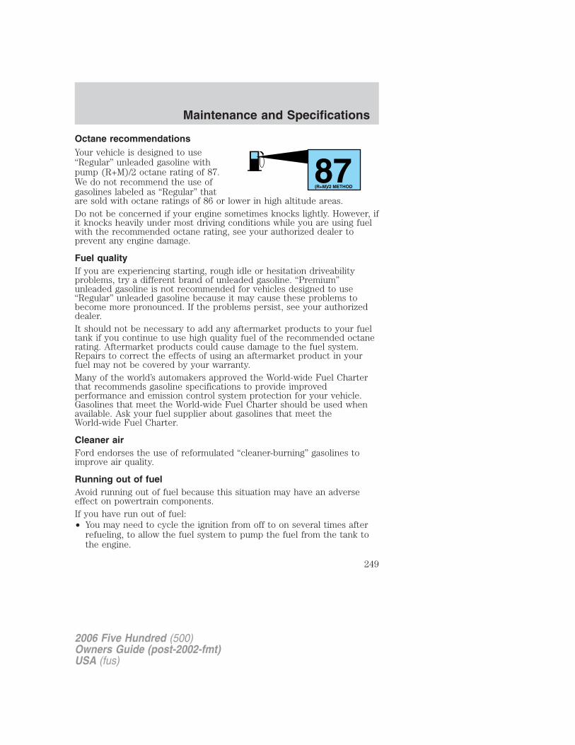
Octane recommendationsYour vehicle is designed to use“Regular” unleaded gasoline withpump (R+M)/2 octane rating of 87.We do not recommend the use ofgasolines labeled as “Regular” thatare sold with octane ratings of 86 or lower in high altitude areas.Do not be concerned if your engine sometimes knocks lightly. However, ifit knocks heavily under most driving conditions while you are using fuelwith the recommended octane rating, see your authorized dealer toprevent any engine damage.
Fuel qualityIf you are experiencing starting, rough idle or hesitation driveabilityproblems, try a different brand of unleaded gasoline. “Premium”unleaded gasoline is not recommended for vehicles designed to use“Regular” unleaded gasoline because it may cause these problems tobecome more pronounced. If the problems persist, see your authorizeddealer.It should not be necessary to add any aftermarket products to your fueltank if you continue to use high quality fuel of the recommended octanerating. Aftermarket products could cause damage to the fuel system.Repairs to correct the effects of using an aftermarket product in yourfuel may not be covered by your warranty.Many of the world’s automakers approved the World-wide Fuel Charterthat recommends gasoline specifications to provide improvedperformance and emission control system protection for your vehicle.Gasolines that meet the World-wide Fuel Charter should be used whenavailable. Ask your fuel supplier about gasolines that meet theWorld-wide Fuel Charter.
Cleaner airFord endorses the use of reformulated “cleaner-burning” gasolines toimprove air quality.
Running out of fuelAvoid running out of fuel because this situation may have an adverseeffect on powertrain components.If you have run out of fuel:• You may need to cycle the ignition from off to on several times after
refueling, to allow the fuel system to pump the fuel from the tank tothe engine.
87(R+M)/2 METHOD
2006 Five Hundred (500)Owners Guide (post-2002-fmt)USA (fus)
Maintenance and Specifications
249
• The indicator may come on. For more information on the “checkengine” or the “service engine soon” indicator, refer to Warning lightsand chimes in the Instrument Cluster chapter.
ESSENTIALS OF GOOD FUEL ECONOMY
Measuring techniquesYour best source of information about actual fuel economy is you, thedriver. You must gather information as accurately and consistently aspossible. Fuel expense, frequency of fill-ups or fuel gauge readings areNOT accurate as a measure of fuel economy. We do not recommendtaking fuel economy measurements during the first 1,000 miles (1,600km) of driving (engine break-in period). You will get a more accuratemeasurement after 2,000 miles-3,000 miles (3,000 km–5,000 km).
Filling the tankThe advertised fuel capacity of the fuel tank on your vehicle is equal tothe rated refill capacity of the fuel tank as listed in the Refill capacitiessection of this chapter.
The advertised capacity is the amount of the indicated capacity and theempty reserve combined. Indicated capacity is the difference in theamount of fuel in a full tank and a tank when the fuel gauge indicatesempty. Empty reserve is the small amount of fuel remaining in the fueltank after the fuel gauge indicates empty.
The amount of usable fuel in the empty reserve varies and shouldnot be relied upon to increase driving range. When refueling yourvehicle after the fuel gauge indicates empty, you might not beable to refuel the full amount of the advertised capacity of thefuel tank due to the empty reserve still present in the tank.
For consistent results when filling the fuel tank:
• Turn the engine/ignition switch to the off position prior to refueling,an error in the reading will result if the engine is left running.
• Use the same filling rate setting (low — medium — high) each timethe tank is filled.
• Allow no more than two automatic click-offs when filling.
• Always use fuel with the recommended octane rating.
• Use a known quality gasoline, preferably a national brand.
• Use the same side of the same pump and have the vehicle facing thesame direction each time you fill up.
2006 Five Hundred (500)Owners Guide (post-2002-fmt)USA (fus)
Maintenance and Specifications
250
• Have the vehicle loading and distribution the same every time.Your results will be most accurate if your filling method is consistent.
Calculating fuel economy1. Fill the fuel tank completely and record the initial odometer reading(in miles or kilometers).2. Each time you fill the tank, record the amount of fuel added (ingallons or liters).3. After at least three to five tank fill-ups, fill the fuel tank and recordthe current odometer reading.4. Subtract your initial odometer reading from the current odometerreading.5. Follow one of the simple calculations in order to determine fueleconomy:
Calculation 1: Divide total miles traveled by total gallons used.
Calculation 2: Multiply liters used by 100, then divide by totalkilometers traveled.
Keep a record for at least one month and record the type of driving (cityor highway). This will provide an accurate estimate of the vehicle’s fueleconomy under current driving conditions. Additionally, keeping recordsduring summer and winter will show how temperature impacts fueleconomy. In general, lower temperatures give lower fuel economy.
Driving style — good driving and fuel economy habitsGive consideration to the lists that follow and you may be able to changea number of variables and improve your fuel economy.
Habits• Smooth, moderate operation can yield up to 10% savings in fuel.
• Steady speeds without stopping will usually give the best fueleconomy.
• Idling for long periods of time (greater than one minute) may wastefuel.
• Anticipate stopping; slowing down may eliminate the need to stop.
• Sudden or hard accelerations may reduce fuel economy.
• Slow down gradually.
• Driving at reasonable speeds (traveling at 55 mph [88 km/h] uses 15%less fuel than traveling at 65 mph [105 km/h]).
2006 Five Hundred (500)Owners Guide (post-2002-fmt)USA (fus)
Maintenance and Specifications
251
• Revving the engine before turning it off may reduce fuel economy.• Using the air conditioner or defroster may reduce fuel economy.• You may want to turn off the speed control in hilly terrain if unnecessary
shifting between third and fourth gear occurs. Unnecessary shifting ofthis type could result in reduced fuel economy.
• Warming up a vehicle on cold mornings is not required and mayreduce fuel economy.
• Resting your foot on the brake pedal while driving may reduce fueleconomy.
• Combine errands and minimize stop-and-go driving.
Maintenance• Keep tires properly inflated and use only recommended size.
• Operating a vehicle with the wheels out of alignment will reduce fueleconomy.
• Use recommended engine oil. Refer to Lubricant specifications inthis chapter.
• Perform all regularly scheduled maintenance items. Follow therecommended maintenance schedule and owner maintenance checksfound in scheduled maintenance information.
Conditions• Heavily loading a vehicle or towing a trailer may reduce fuel economy
at any speed.
• Carrying unnecessary weight may reduce fuel economy (approximately1 mpg [0.4 km/L] is lost for every 400 lb [180 kg] of weight carried).
• Adding certain accessories to your vehicle (for example bugdeflectors, rollbars/light bars, running boards, ski/luggage racks) mayreduce fuel economy.
• Using fuel blended with alcohol may lower fuel economy.
• Fuel economy may decrease with lower temperatures during the first8–10 miles (12–16 km) of driving.
• Driving on flat terrain offers improved fuel economy as compared todriving on hilly terrain.
• Transmissions give their best fuel economy when operated in the topcruise gear and with steady pressure on the gas pedal.
• Close windows for high speed driving.
2006 Five Hundred (500)Owners Guide (post-2002-fmt)USA (fus)
Maintenance and Specifications
252
EPA window sticker
Every new vehicle should have the EPA window sticker. Contact yourauthorized dealer if the window sticker is not supplied with your vehicle.The EPA window sticker should be your guide for the fuel economycomparisons with other vehicles.
It is important to note the box in the lower left corner of the windowsticker. These numbers represent the Range of MPG (L/100 km)expected on the vehicle under optimum conditions. Your fuel economymay vary depending upon the method of operation and conditions.
EMISSION CONTROL SYSTEM
Your vehicle is equipped with various emission control components and acatalytic converter which will enable your vehicle to comply withapplicable exhaust emission standards. To make sure that the catalyticconverter and other emission control components continue to workproperly:
• Use only the specified fuel listed.
• Avoid running out of fuel.
• Do not turn off the ignition while your vehicle is moving, especially athigh speeds.
• Have the items listed in scheduled maintenance informationperformed according to the specified schedule.
The scheduled maintenance items listed in scheduled maintenanceinformation are essential to the life and performance of your vehicleand to its emissions system.
If other than Ford, Motorcraft or Ford-authorized parts are used formaintenance replacements or for service of components affectingemission control, such non-Ford parts should be equivalent to genuineFord Motor Company parts in performance and durability.
Do not park, idle, or drive your vehicle in dry grass or other dryground cover. The emission system heats up the engine
compartment and exhaust system, which can start a fire.
Illumination of the indicator, charging system warning light or thetemperature warning light, fluid leaks, strange odors, smoke or loss ofengine power could indicate that the emission control system is notworking properly.
2006 Five Hundred (500)Owners Guide (post-2002-fmt)USA (fus)
Maintenance and Specifications
253
Exhaust leaks may result in entry of harmful and potentiallylethal fumes into the passenger compartment.
Do not make any unauthorized changes to your vehicle or engine. Bylaw, vehicle owners and anyone who manufactures, repairs, services,sells, leases, trades vehicles, or supervises a fleet of vehicles are notpermitted to intentionally remove an emission control device or preventit from working. Information about your vehicle’s emission system is onthe Vehicle Emission Control Information Decal located on or near theengine. This decal identifies engine displacement and gives some tune upspecifications.
Please consult your Warranty Guide for complete emission warrantyinformation.
On board diagnostics (OBD-II)Your vehicle is equipped with a computer that monitors the engine’semission control system. This system is commonly known as the OnBoard Diagnostics System (OBD-II). This OBD-II system protects theenvironment by ensuring that your vehicle continues to meetgovernment emission standards. The OBD-II system also assists yourauthorized dealer in properly servicing your vehicle. When theindicator illuminates, the OBD-II system has detected a malfunction.Temporary malfunctions may cause the indicator to illuminate.Examples are:
1. The vehicle has run out of fuel—the engine may misfire or run poorly.
2. Poor fuel quality or water in the fuel.
3. The fuel cap may not have been securely tightened. See Fuel fillercap in this chapter.
These temporary malfunctions can be corrected by filling the fuel tankwith good quality fuel and/or properly tightening the fuel cap. After threedriving cycles without these or any other temporary malfunctionspresent, the indicator should turn off—A driving cycle consists of acold engine startup followed by mixed city/highway driving. No additionalvehicle service is required.
If the indicator remains on, have your vehicle serviced at the firstavailable opportunity.
2006 Five Hundred (500)Owners Guide (post-2002-fmt)USA (fus)
Maintenance and Specifications
254
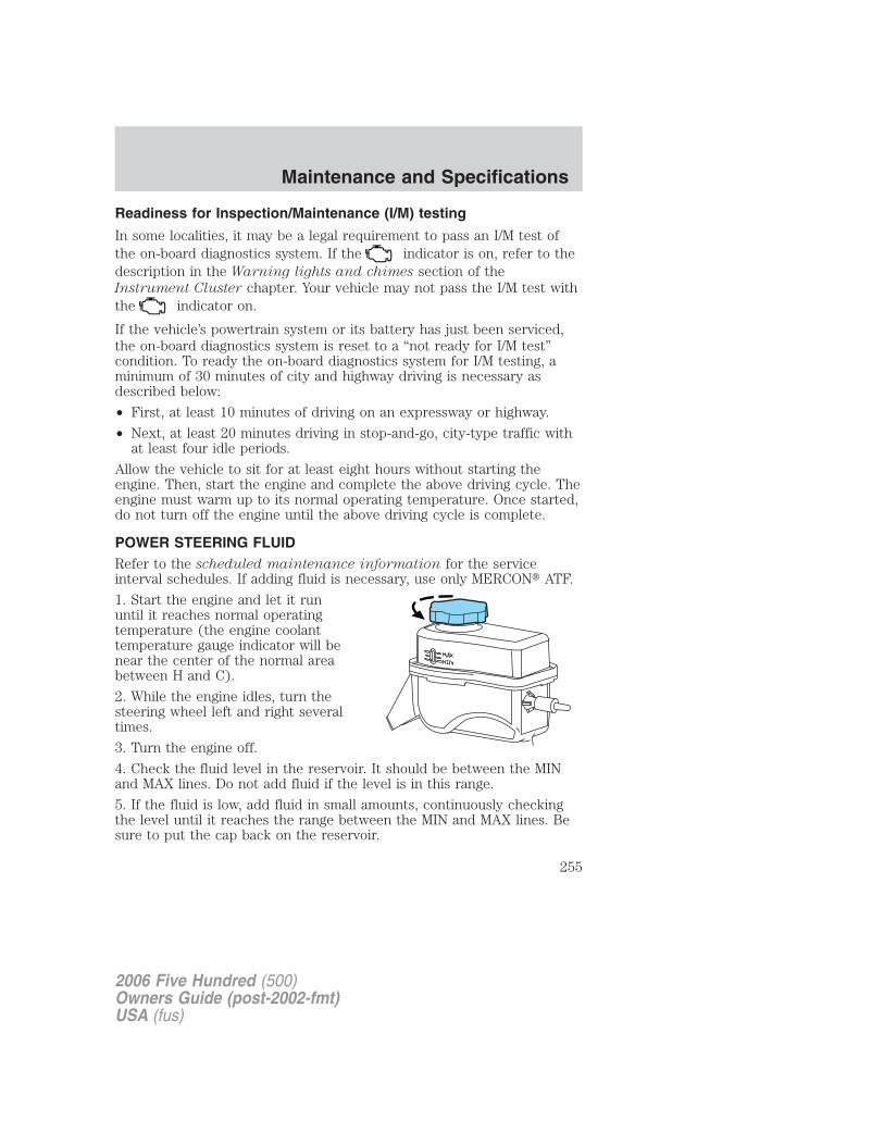
Readiness for Inspection/Maintenance (I/M) testing
In some localities, it may be a legal requirement to pass an I/M test ofthe on-board diagnostics system. If the indicator is on, refer to thedescription in the Warning lights and chimes section of theInstrument Cluster chapter. Your vehicle may not pass the I/M test withthe indicator on.
If the vehicle’s powertrain system or its battery has just been serviced,the on-board diagnostics system is reset to a “not ready for I/M test”condition. To ready the on-board diagnostics system for I/M testing, aminimum of 30 minutes of city and highway driving is necessary asdescribed below:
• First, at least 10 minutes of driving on an expressway or highway.
• Next, at least 20 minutes driving in stop-and-go, city-type traffic withat least four idle periods.
Allow the vehicle to sit for at least eight hours without starting theengine. Then, start the engine and complete the above driving cycle. Theengine must warm up to its normal operating temperature. Once started,do not turn off the engine until the above driving cycle is complete.
POWER STEERING FLUIDRefer to the scheduled maintenance information for the serviceinterval schedules. If adding fluid is necessary, use only MERCON� ATF.
1. Start the engine and let it rununtil it reaches normal operatingtemperature (the engine coolanttemperature gauge indicator will benear the center of the normal areabetween H and C).
2. While the engine idles, turn thesteering wheel left and right severaltimes.
3. Turn the engine off.
4. Check the fluid level in the reservoir. It should be between the MINand MAX lines. Do not add fluid if the level is in this range.
5. If the fluid is low, add fluid in small amounts, continuously checkingthe level until it reaches the range between the MIN and MAX lines. Besure to put the cap back on the reservoir.
2006 Five Hundred (500)Owners Guide (post-2002-fmt)USA (fus)
Maintenance and Specifications
255
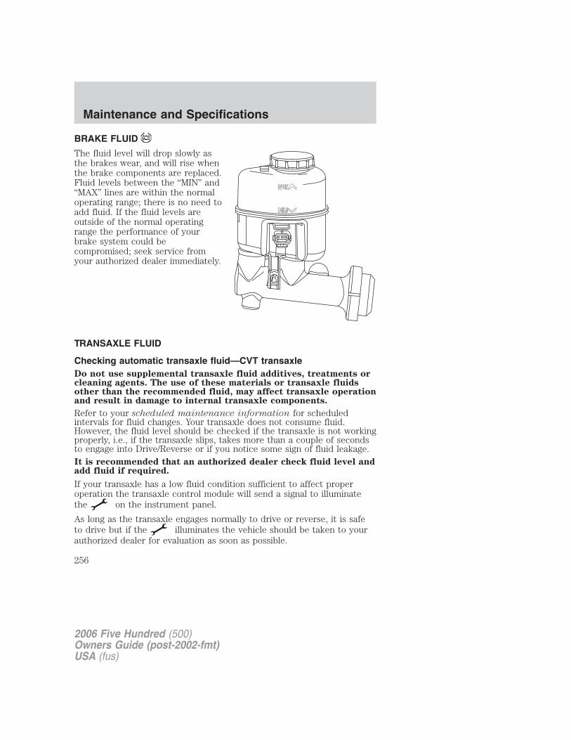
BRAKE FLUID
The fluid level will drop slowly asthe brakes wear, and will rise whenthe brake components are replaced.Fluid levels between the “MIN” and“MAX” lines are within the normaloperating range; there is no need toadd fluid. If the fluid levels areoutside of the normal operatingrange the performance of yourbrake system could becompromised; seek service fromyour authorized dealer immediately.
TRANSAXLE FLUID
Checking automatic transaxle fluid—CVT transaxleDo not use supplemental transaxle fluid additives, treatments orcleaning agents. The use of these materials or transaxle fluidsother than the recommended fluid, may affect transaxle operationand result in damage to internal transaxle components.
Refer to your scheduled maintenance information for scheduledintervals for fluid changes. Your transaxle does not consume fluid.However, the fluid level should be checked if the transaxle is not workingproperly, i.e., if the transaxle slips, takes more than a couple of secondsto engage into Drive/Reverse or if you notice some sign of fluid leakage.It is recommended that an authorized dealer check fluid level andadd fluid if required.
If your transaxle has a low fluid condition sufficient to affect properoperation the transaxle control module will send a signal to illuminatethe on the instrument panel.
As long as the transaxle engages normally to drive or reverse, it is safeto drive but if the illuminates the vehicle should be taken to yourauthorized dealer for evaluation as soon as possible.
2006 Five Hundred (500)Owners Guide (post-2002-fmt)USA (fus)
Maintenance and Specifications
256
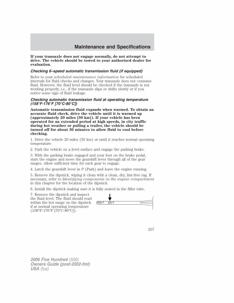
If your transaxle does not engage normally, do not attempt todrive. The vehicle should be towed to your authorized dealer forevaluation.
Checking 6–speed automatic transmission fluid (if equipped)
Refer to your scheduled maintenance information for scheduledintervals for fluid checks and changes. Your transaxle does not consumefluid. However, the fluid level should be checked if the transaxle is notworking properly, i.e., if the transaxle slips or shifts slowly or if younotice some sign of fluid leakage.
Checking automatic transmission fluid at operating temperature(158°F-176°F [70°C-80°C])
Automatic transmission fluid expands when warmed. To obtain anaccurate fluid check, drive the vehicle until it is warmed up(approximately 20 miles [30 km]). If your vehicle has beenoperated for an extended period at high speeds, in city trafficduring hot weather or pulling a trailer, the vehicle should beturned off for about 30 minutes to allow fluid to cool beforechecking.
1. Drive the vehicle 20 miles (30 km) or until it reaches normal operatingtemperature.
2. Park the vehicle on a level surface and engage the parking brake.
3. With the parking brake engaged and your foot on the brake pedal,start the engine and move the gearshift lever through all of the gearranges. Allow sufficient time for each gear to engage.
4. Latch the gearshift lever in P (Park) and leave the engine running.
5. Remove the dipstick, wiping it clean with a clean, dry, lint-free rag. Ifnecessary, refer to Identifying components in the engine compartmentin this chapter for the location of the dipstick.
6. Install the dipstick making sure it is fully seated in the filler tube.
7. Remove the dipstick and inspectthe fluid level. The fluid should readwithin the hot range on the dipstickif at normal operating temperature(158°F-176°F [70°C-80°C]).
2006 Five Hundred (500)Owners Guide (post-2002-fmt)USA (fus)
Maintenance and Specifications
257
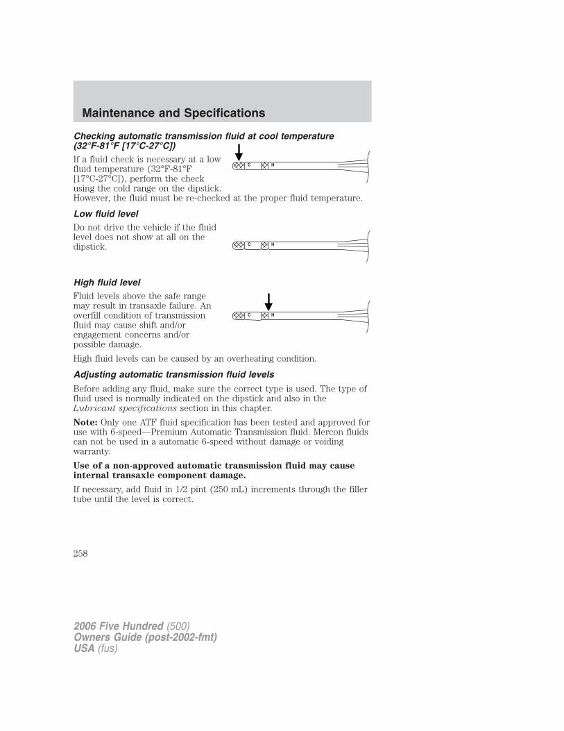
Checking automatic transmission fluid at cool temperature(32°F-81°F [17°C-27°C])If a fluid check is necessary at a lowfluid temperature (32°F-81°F[17°C-27°C]), perform the checkusing the cold range on the dipstick.However, the fluid must be re-checked at the proper fluid temperature.
Low fluid levelDo not drive the vehicle if the fluidlevel does not show at all on thedipstick.
High fluid levelFluid levels above the safe rangemay result in transaxle failure. Anoverfill condition of transmissionfluid may cause shift and/orengagement concerns and/orpossible damage.
High fluid levels can be caused by an overheating condition.
Adjusting automatic transmission fluid levels
Before adding any fluid, make sure the correct type is used. The type offluid used is normally indicated on the dipstick and also in theLubricant specifications section in this chapter.
Note: Only one ATF fluid specification has been tested and approved foruse with 6-speed—Premium Automatic Transmission fluid. Mercon fluidscan not be used in a automatic 6-speed without damage or voidingwarranty.
Use of a non-approved automatic transmission fluid may causeinternal transaxle component damage.
If necessary, add fluid in 1/2 pint (250 mL) increments through the fillertube until the level is correct.
2006 Five Hundred (500)Owners Guide (post-2002-fmt)USA (fus)
Maintenance and Specifications
258
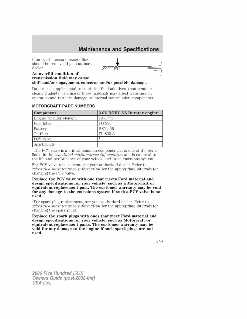
If an overfill occurs, excess fluidshould be removed by an authorizeddealer.
An overfill condition oftransmission fluid may cause
shift and/or engagement concerns and/or possible damage.
Do not use supplemental transmission fluid additives, treatments orcleaning agents. The use of these materials may affect transmissionoperation and result in damage to internal transmission components.
MOTORCRAFT PART NUMBERS
Component 3.0L DOHC V6 Duratec engine
Engine air filter element FA-1771Fuel filter FG-986Battery BXT-36ROil filter FL-820-SPCV valve 1
Spark plugs 2
1The PCV valve is a critical emission component. It is one of the itemslisted in the scheduled maintenance information and is essential tothe life and performance of your vehicle and to its emissions system.
For PCV valve replacement, see your authorized dealer. Refer toscheduled maintenance information for the appropriate intervals forchanging the PCV valve.
Replace the PCV valve with one that meets Ford material anddesign specifications for your vehicle, such as a Motorcraft orequivalent replacement part. The customer warranty may be voidfor any damage to the emissions system if such a PCV valve is notused.2For spark plug replacement, see your authorized dealer. Refer toscheduled maintenance information for the appropriate intervals forchanging the spark plugs.
Replace the spark plugs with ones that meet Ford material anddesign specifications for your vehicle, such as Motorcraft orequivalent replacement parts. The customer warranty may bevoid for any damage to the engine if such spark plugs are notused.
2006 Five Hundred (500)Owners Guide (post-2002-fmt)USA (fus)
Maintenance and Specifications
259

REFILL CAPACITIES
Fluid Ford Part
Name
Application Capacity
Brake fluid Motorcraft HighPerformanceDOT 3 MotorVehicle BrakeFluid
All Between MAXand MIN onreservoir
Enginecoolant1
MotorcraftPremium GoldEngine Coolant(yellow-colored)
3.0L engine 11.6 quarts(11.0L)
Engine oil(includes filterchange)2
Motorcraft SAE5W-20 PremiumSynthetic BlendMotor Oil (US)Motorcraft SAE5W-20 SuperPremium MotorOil (Canada)
3.0L engine 6.0 quarts (5.7L)
Fuel tankcapacity
N/A All 20.0 gallons(75.7)
Power steeringfluid
MotorcraftMERCON� ATF
3.0L engine Between MAXand MIN onreservoir
Automatictransaxle
MotorcraftContinuouslyVariable ChainTypeTransmissionFluid3
CVT automatictransaxle
10.0 quarts(9.5L)4
PremiumAutomaticTransmissionFluid3
6–speedautomatictransaxle
7.4 quarts (7.0L)4
2006 Five Hundred (500)Owners Guide (post-2002-fmt)USA (fus)
Maintenance and Specifications
260
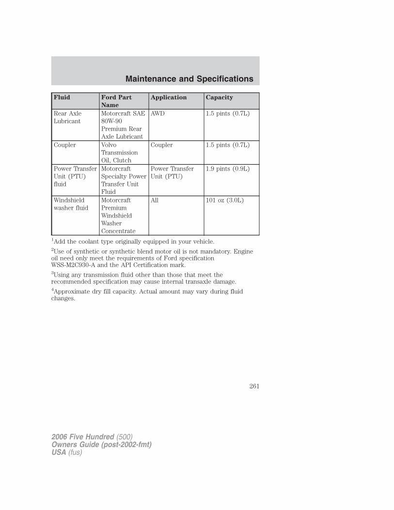
Fluid Ford Part
Name
Application Capacity
Rear AxleLubricant
Motorcraft SAE80W-90Premium RearAxle Lubricant
AWD 1.5 pints (0.7L)
Coupler VolvoTransmissionOil, Clutch
Coupler 1.5 pints (0.7L)
Power TransferUnit (PTU)fluid
MotorcraftSpecialty PowerTransfer UnitFluid
Power TransferUnit (PTU)
1.9 pints (0.9L)
Windshieldwasher fluid
MotorcraftPremiumWindshieldWasherConcentrate
All 101 oz (3.0L)
1Add the coolant type originally equipped in your vehicle.2Use of synthetic or synthetic blend motor oil is not mandatory. Engineoil need only meet the requirements of Ford specificationWSS-M2C930-A and the API Certification mark.3Using any transmission fluid other than those that meet therecommended specification may cause internal transaxle damage.4Approximate dry fill capacity. Actual amount may vary during fluidchanges.
2006 Five Hundred (500)Owners Guide (post-2002-fmt)USA (fus)
Maintenance and Specifications
261
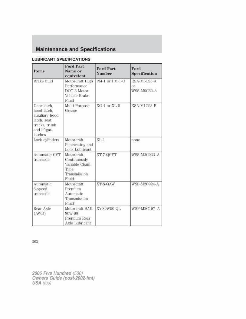
LUBRICANT SPECIFICATIONS
Items
Ford Part
Name or
equivalent
Ford Part
Number
Ford
Specification
Brake fluid Motorcraft HighPerformanceDOT 3 MotorVehicle BrakeFluid
PM-1 or PM-1-C ESA-M6C25-AorWSS-M6C62-A
Door latch,hood latch,auxiliary hoodlatch, seattracks, trunkand liftgatelatches
Multi-PurposeGrease
XG-4 or XL-5 ESA-M1C93-B
Lock cylinders MotorcraftPenetrating andLock Lubricant
XL-1 none
Automatic CVTtransaxle
MotorcraftContinuouslyVariable ChainTypeTransmissionFluid1
XT-7-QCFT WSS-M2C933–A
Automatic6-speedtransaxle
MotorcraftPremiumAutomaticTransmissionFluid1
XT-8-QAW WSS-M2C924-A
Rear Axle(AWD)
Motorcraft SAE80W-90Premium RearAxle Lubricant
XY-80W90-QL WSP-M2C197–A
2006 Five Hundred (500)Owners Guide (post-2002-fmt)USA (fus)
Maintenance and Specifications
262
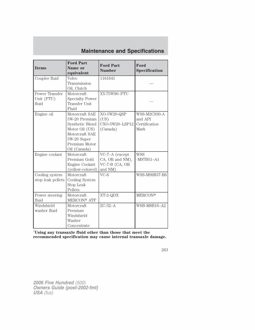
Items
Ford Part
Name or
equivalent
Ford Part
Number
Ford
Specification
Coupler fluid VolvoTransmissionOil, Clutch
1161641—
Power TransferUnit (PTU)fluid
MotorcraftSpecialty PowerTransfer UnitFluid
XY-75W90–PTU
—
Engine oil Motorcraft SAE5W-20 PremiumSynthetic BlendMotor Oil (US)Motorcraft SAE5W-20 SuperPremium MotorOil (Canada)
XO-5W20-QSP(US)CXO-5W20–LSP12(Canada)
WSS-M2C930-Aand APICertificationMark
Engine coolant MotorcraftPremium GoldEngine Coolant(yellow-colored)
VC-7–A (exceptCA, OR and NM),VC-7-B (CA, ORand NM)
WSS-M97B51–A1
Cooling systemstop leak pellets
MotorcraftCooling SystemStop LeakPellets
VC-6 WSS-M99B37-B6
Power steeringfluid
MotorcraftMERCON� ATF
XT-2-QDX MERCON�
Windshieldwasher fluid
MotorcraftPremiumWindshieldWasherConcentrate
ZC-32–A WSB-M8B16–A2
1Using any transaxle fluid other than those that meet therecommended specification may cause internal transaxle damage.
2006 Five Hundred (500)Owners Guide (post-2002-fmt)USA (fus)
Maintenance and Specifications
263
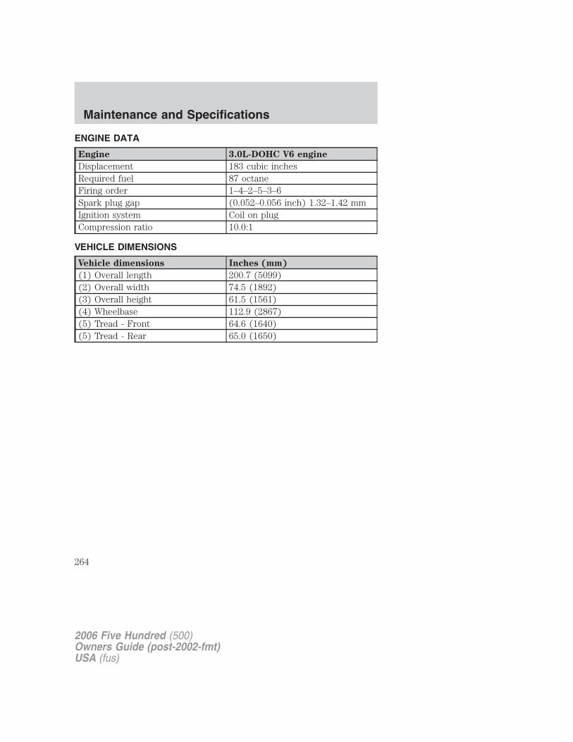
ENGINE DATA
Engine 3.0L-DOHC V6 engine
Displacement 183 cubic inchesRequired fuel 87 octaneFiring order 1–4–2–5–3–6Spark plug gap (0.052–0.056 inch) 1.32–1.42 mmIgnition system Coil on plugCompression ratio 10.0:1
VEHICLE DIMENSIONS
Vehicle dimensions Inches (mm)
(1) Overall length 200.7 (5099)(2) Overall width 74.5 (1892)(3) Overall height 61.5 (1561)(4) Wheelbase 112.9 (2867)(5) Tread - Front 64.6 (1640)(5) Tread - Rear 65.0 (1650)
2006 Five Hundred (500)Owners Guide (post-2002-fmt)USA (fus)
Maintenance and Specifications
264
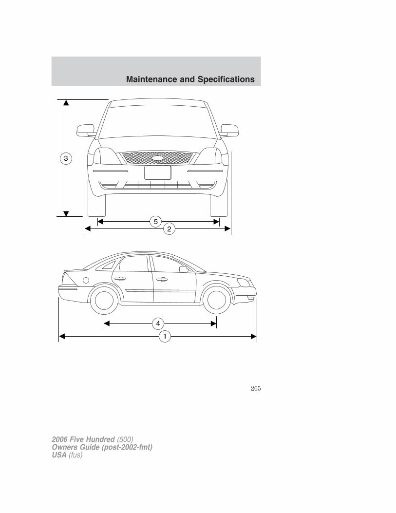
52
3
2006 Five Hundred (500)Owners Guide (post-2002-fmt)USA (fus)
Maintenance and Specifications
265
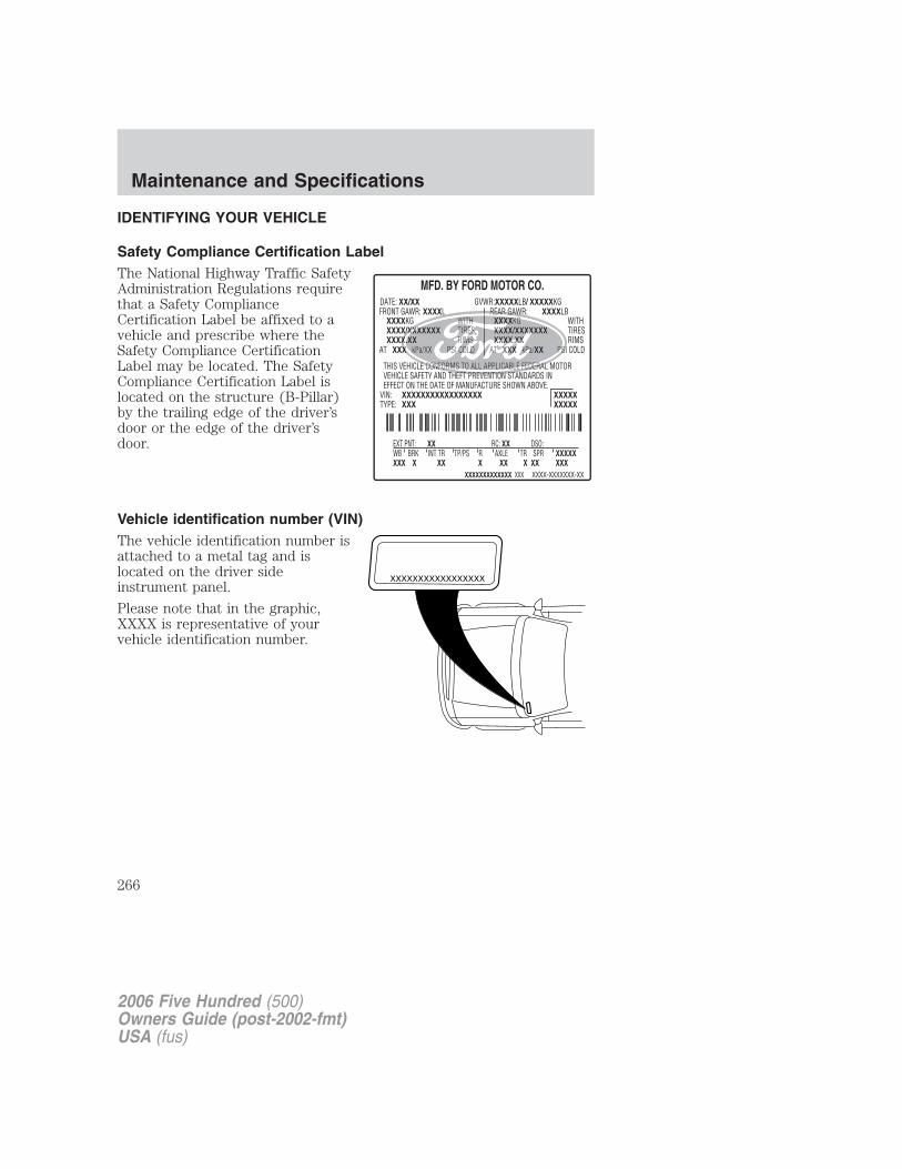
IDENTIFYING YOUR VEHICLE
Safety Compliance Certification LabelThe National Highway Traffic SafetyAdministration Regulations requirethat a Safety ComplianceCertification Label be affixed to avehicle and prescribe where theSafety Compliance CertificationLabel may be located. The SafetyCompliance Certification Label islocated on the structure (B-Pillar)by the trailing edge of the driver’sdoor or the edge of the driver’sdoor.
Vehicle identification number (VIN)The vehicle identification number isattached to a metal tag and islocated on the driver sideinstrument panel.
Please note that in the graphic,XXXX is representative of yourvehicle identification number.
XXXXXXXXXXXXXXXXX
2006 Five Hundred (500)Owners Guide (post-2002-fmt)USA (fus)
Maintenance and Specifications
266
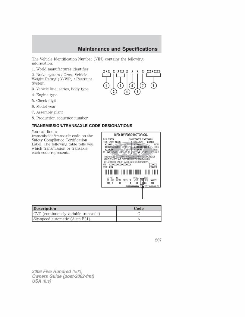
The Vehicle Identification Number (VIN) contains the followinginformation:
1. World manufacturer identifier
2. Brake system / Gross VehicleWeight Rating (GVWR) / RestraintSystem
3. Vehicle line, series, body type
4. Engine type
5. Check digit
6. Model year
7. Assembly plant
8. Production sequence number
TRANSMISSION/TRANSAXLE CODE DESIGNATIONSYou can find atransmission/transaxle code on theSafety Compliance CertificationLabel. The following table tells youwhich transmission or transaxleeach code represents.
Description Code
CVT (continuously variable transaxle) CSix-speed automatic (Aisin F21) A
2006 Five Hundred (500)Owners Guide (post-2002-fmt)USA (fus)
Maintenance and Specifications
267
GENUINE FORD ACCESSORIES FOR YOUR VEHICLEA wide selection of Genuine Ford Accessories are available for yourvehicle through your local Ford or Ford of Canada dealer. These qualityaccessories have been specifically engineered to fulfill your automotiveneeds; they are custom designed to complement the style andaerodynamic appearance of your vehicle. In addition, each accessory ismade from high quality materials and meets or exceeds Ford’s rigorousengineering and safety specifications. Ford Motor Company will repair orreplace any properly dealer-installed Genuine Ford Accessories found tobe defective in factory-supplied materials or workmanship during thewarranty period, as well as any component damaged by the defectiveaccessory. The accessories will be warranted for whichever provides youthe greatest benefit:
• 12 months or 12,000 miles (20,000 km) (whichever occurs first), or
• the remainder of your new vehicle limited warranty.
This means that Genuine Ford Accessories purchased along with yournew vehicle and installed by a dealer are covered for the full length ofyour New Vehicle’s Limited Warranty — 3 years or 36,000 miles (60,000km) (whichever occurs first). Contact your dealer for details and a copyof the warranty.
Not all accessories are available for all models.
The following is a list of several Genuine Ford Accessories. Not allaccessories are available for all models. For a complete listing of theaccessories that are available for your vehicle, please contact your dealeror visit our online store at: www.fordaccessoriesstore.com.
Exterior styleBug shields
Front end covers
Side window air deflectors
Moonroof air deflectors
Splash guards
Wheels
2006 Five Hundred (500)Owners Guide (post-2002-fmt)USA (fus)
Accessories
268
Interior styleElectrochromic compass/temperature/Homelink options
Floor mats
Scuff plates
LifestyleEngine block heaters
Interior cargo organization and management
Smoker’s pack
Peace of mindFirst aid kits
Full vehicle covers
Highway safety kits
Keyless entry keypads
Locking gas cap
Mobile-Ease� hands free communication system
Remote start
Vehicle security systems
Wheel locks
For maximum vehicle performance, keep the following information inmind when adding accessories or equipment to your vehicle:
• When adding accessories, equipment, passengers and luggage to yourvehicle, do not exceed the total weight capacity of the vehicle or ofthe front or rear axle (GVWR or GAWR as indicated on the SafetyCompliance Certification label). Consult your authorized dealer forspecific weight information.
• The Federal Communications Commission (FCC) and Canadian RadioTelecommunications Commission (CRTC) regulate the use of mobilecommunications systems — such as two-way radios, telephones andtheft alarms - that are equipped with radio transmitters. Any suchequipment installed in your vehicle should comply with FCC or CRTCregulations and should be installed only by a qualified servicetechnician.
2006 Five Hundred (500)Owners Guide (post-2002-fmt)USA (fus)
Accessories
269
• Mobile communications systems may harm the operation of yourvehicle, particularly if they are not properly designed for automotiveuse.
• To avoid interference with other vehicle functions, such as anti-lockbraking systems, amateur radio users who install radios and antennasonto their vehicle should not locate the Amateur Radio Antennas inthe area of the driver’s side hood.
• Electrical or electronic accessories or components that are added tothe vehicle by the authorized dealer or the owner may adversely affectbattery performance and durability.
2006 Five Hundred (500)Owners Guide (post-2002-fmt)USA (fus)
Accessories
270
A
Accessory delay ..........................63Air cleaner filter .......................259Air conditioning ....................42, 44Airbag supplemental restraintsystem ........................123, 132, 134
and child safety seats ............125description ..............123, 132, 134disposal ....................................137driver airbag ............125, 133, 135indicator light .................131, 137operation .................125, 133, 135passenger airbag .....125, 133, 135side airbag ...............................132
All Wheel Drive (AWD),driving off road .........................185Antifreeze(see Engine coolant) ................239Anti-lock brake system(see Brakes) ..............................176Anti-theft system ..................96, 99
arming the system ....................99disarming a triggeredsystem .....................................100triggering .................................100
Audio system (see Radio) ...17, 20Automatic transaxle
fluid, adding ....................256–257fluid, checking ................256–257fluid, refill capacities ..............260fluid, specification ..................264
Automatic transmissiondriving an automaticoverdrive .........................181–182
Axlelubricant specifications ..........262
B
Battery .......................................237
acid, treating emergencies .....237jumping a disabled battery ....208maintenance-free ....................237replacement, specifications ...259servicing ..................................237
BeltMinder� ...............................117Brakes ........................................175
anti-lock ...................................176anti-lock brake system (ABS)warning light ...........................176fluid, checking and adding ....256fluid, refill capacities ..............260fluid, specifications .........262, 264lubricant specifications ..262, 264parking ....................................177shift interlock ..........................179
Bulbs ............................................52
C
Capacities for refilling fluids ....260
Cargo net .....................................83
Cassette tape player ...................17
Cell phone use ..............................7
Changing a tire .........................201
Child safety restraints ..............138child safety belts ....................138
Child safety seats ......................141attaching with tether straps ..145in front seat ............................142in rear seat ..............................142
Cleaning your vehicleengine compartment ..............225instrument panel ....................226interior .....................................227interior trim ............................227plastic parts ............................225washing ....................................223waxing .....................................224
2006 Five Hundred (500)Owners Guide (post-2002-fmt)USA (fus)
Index
271
wheels ......................................224wiper blades ............................226
Climate control (see Airconditioning or Heating) ......42, 44
Clock ............................................60
Clock adjust6-CD in dash .............................21AM/FM/CD .................................17
Compass, electronicset zone adjustment .................76
Console ........................................60overhead ..............................59–60
Controlspower seat ...............................104steering column ........................68
Coolantchecking and adding ..............239refill capacities ................244, 260specifications ..................262, 264
Cruise control(see Speed control) ....................65
Cupholder(s) .............................108
Customer Assistance ................192Ford Extended ServicePlan ..........................................220Getting assistance outside theU.S. and Canada .....................221Getting roadside assistance ...192Getting the service youneed .........................................216Ordering additional owner’sliterature .................................222Utilizing theMediation/ArbitrationProgram ...................................220
D
Daytime running lamps(see Lamps) ................................50Dipstick
automatic transmissionfluid ..................................256–257engine oil .................................234
Doorslubricant specifications ..........262
Driving under specialconditions ..........................186, 189
sand .........................................188snow and ice ...........................190through water .................188, 191
E
Electronic message center .........74
Emergencies, roadsidejump-starting ..........................208
Emission control system ..........253
Engine ........................................264cleaning ...................................225coolant .....................................239idle speed control ...................237lubrication specifications ......262,
264refill capacities ........................260service points ..........................232starting after a collision .........194
Engine block heater .................175
Engine oil ..................................234change oil soon warning,message center .......................234checking and adding ..............234dipstick ....................................234filter, specifications ........236, 259recommendations ...................236refill capacities ........................260
2006 Five Hundred (500)Owners Guide (post-2002-fmt)USA (fus)
Index
272
specifications ..................262, 264Exhaust fumes ..........................175
F
Fluid capacities .........................260Foglamps .....................................49Four-Wheel Drive vehicles
driving off road .......................185Fuel ............................................245
calculating fueleconomy ............................75, 250cap ...........................................247capacity ...................................260choosing the right fuel ...........248comparisons with EPA fueleconomy estimates .................253detergent in fuel .....................249filling your vehicle withfuel ...........................245, 247, 250filter, specifications ........245, 259fuel pump shut-off switch .....194improving fuel economy ........250octane rating ...................249, 264quality ......................................249running out of fuel .................249safety information relating toautomotive fuels .....................245
Fuel pump shut-off switch .......194
Fuses ..........................................195
G
Gas cap (see Fuel cap) ............247
Gas mileage(see Fuel economy) .................250
Gauges .........................................14
H
Hazard flashers .........................194
Head restraints .................101, 107Headlamps ...................................48
aiming ........................................50autolamp system .......................48bulb specifications ....................53daytime running lights .............50flash to pass ..............................49high beam .................................49replacing bulbs ...................53–54turning on and off ....................48
Heatingheating and air conditioningsystem ...........................40, 42, 44
Homelink wireless controlsystem ..........................................70Hood ..........................................231
I
Ignition ...............................172, 264Illuminated visor mirror .............59Infant seats(see Safety seats) .....................141Inspection/maintenance (I/M)testing ........................................255Instrument panel ........................60
cleaning ...................................226cluster ........................................10lighting up panel andinterior .......................................50
J
Jack ............................................201positioning ...............................201storage .....................................201
Jump-starting your vehicle ......208
K
Keyless entry system .................93
2006 Five Hundred (500)Owners Guide (post-2002-fmt)USA (fus)
Index
273
autolock .....................................94keypad .......................................93locking and unlocking doors ....94programming entry code .........93
Keys .............................................97positions of the ignition .........172
L
Lampsautolamp system .......................48bulb replacementspecifications chart ..................53daytime running light ...............50fog lamps ...................................49headlamps .................................48headlamps, flash to pass ..........49instrument panel, dimming .....50interior lamps ...........................52replacing bulbs .............53–54, 57
Lane change indicator(see Turn signal) ........................52
Lights, warning and indicator ....10anti-lock brakes (ABS) ..........176
Load limits .................................163
Locksautolock .....................................94childproof ..................................85doors ..........................................84
Lubricant specifications ...262, 264
Lug nuts ....................................208
Lumbar support, seats .............102
M
Message center ...........................74english/metric button ...............79system check button ................79warning messages .....................80
Mirrors .........................................64
automatic dimming rearviewmirror ........................................64fold away ...................................64heated ........................................65side view mirrors (power) .......64
Moon roof ....................................69
Motorcraft parts ........228, 245, 259
N
Navigation system .......................25
O
Octane rating ............................249
Oil (see Engine oil) ..................234
P
Parking brake ............................177
Parts (see Motorcraft parts) ....259
Passenger OccupantClassification Sensor .................110
Power adjustable foot pedals .....65
Power distribution box(see Fuses) ...............................198
Power door locks ........................84
Power mirrors .............................64
Power point .................................61
Power steering ..........................178fluid, checking and adding ....255fluid, refill capacity ................260fluid, specifications .........262, 264
Power Windows ...........................61
R
Radio ......................................17, 20
2006 Five Hundred (500)Owners Guide (post-2002-fmt)USA (fus)
Index
274
Relays ........................................195Remote entry system .................87
illuminated entry ................91–92locking/unlocking doors .....87–88opening the trunk .....................88panic alarm ...............................88replacement/additionaltransmitters ...............................90replacing the batteries .............89
Reverse sensing system ...........183
Roadside assistance ..................192
S
Safety Belt Maintenance ..........122
Safety belts (see Safetyrestraints) ..................109, 112–116
Safety Canopy ...........................134
Safety defects, reporting ..........222
Safety restraints ........109, 112–116BeltMinder� ............................117extension assembly ................122for adults .........................113–115for children .....................137–138Occupant ClassificationSensor ......................................110safety belt maintenance .........122warning light and chime ........116
Safety seats for children ..........141
Safety ComplianceCertification Label ....................266
Seat belts(see Safety restraints) .............109
Seats ..........................................101child safety seats ....................141front seats ...............101, 103, 106heated ........................................44memory seat .....................88, 106
SecuriLock passive anti-theftsystem ..........................................96Servicing your vehicle ..............230Setting the clock
AM/FM single CD .....................17AM/FM/In-dash 6 CD ................21
Spare tire(see Changing the Tire) ...........204Spark plugs,specifications .....................259, 264
Specification chart,lubricants ...........................262, 264
Speed control ..............................65
Starting your vehicle ........172–174jump starting ..........................208
Steering wheelcontrols ......................................68tilting .........................................59
T
Tilt steering wheel ......................59
Tires ...........................149–150, 201alignment ................................156care ..........................................153changing ..........................201, 204checking the pressure ............153inflating ...................................151label .........................................162replacing ..................................155rotating ....................................156safety practices .......................155sidewall information ...............158snow tires and chains ............163spare tire .................................202terminology .............................150tire grades ...............................150treadwear ........................149, 154
Towing .......................................169
2006 Five Hundred (500)Owners Guide (post-2002-fmt)USA (fus)
Index
275
recreational towing .................171trailer towing ..........................169wrecker ....................................214
Traction control ........................178
Transaxlefluid, checking and adding(automatic) .....................256–257fluid, refill capacities ..............260lubricant specifications ..........264
Transmission .............................179brake-shift interlock (BSI) ....179lubricant specifications ..........262
Trunk ...........................................85remote release ....................83, 88
Turn signal ..................................52
V
Vehicle dimensions ...................264
Vehicle Identification Number(VIN) ..........................................266
Vehicle loading ..........................163
Ventilating your vehicle ...........175
W
Warning lights (see Lights) .......10
Washer fluid ..............................233
Water, Driving through .............191
Windowspower .........................................61
Windshield washer fluid andwipers
checking and adding fluid .....233operation ...................................58replacing wiper blades ...........233
Wrecker towing .........................214
2006 Five Hundred (500)Owners Guide (post-2002-fmt)USA (fus)
Index
276

277

278

279

280


![[PI00100(ALL)06/95] - fordservicecontent.com · by a network of more than 5,100 participating Ford Motor Company dealers. [IN04600(ALL)05/96] NOTE: ... 07/95] Pollen, bird droppings](https://img.dokumen.tips/doc/110x75/5ad6933a7f8b9a32618b4a57/pi00100all0695-a-network-of-more-than-5100-participating-ford-motor-company.jpg)