Embed Size (px)
Citation preview
TABLE OF CONTENTS
Chassis Dynamics
Subject Page
Objectives of the Module...............................................................................2
Chassis............................................................................................................3Front and Rear Axle.........................................................................................3Springs and Dampers......................................................................................4Parking Brake..................................................................................................4
Electric Power Steering..................................................................................7Purpose of the System....................................................................................7System Components.......................................................................................8Inputs and Outputs........................................................................................11Principle of Operation.....................................................................................12Workshop Hints.............................................................................................14
Dynamic Stability Control.............................................................................17Purpose of the System..................................................................................17Inputs and Outputs........................................................................................18System Components.....................................................................................19
Run Flat Tire (RFT) Technology...................................................................20Purpose of the System..................................................................................20Principle of Operation....................................................................................20System Components.....................................................................................20
Tire Deflation Warning (RPA)........................................................................21Principle of Operation....................................................................................21Initialization/Operation....................................................................................21
Wheel/Tire Styling Combinations................................................................22
Review Questions.........................................................................................24
Chassis Dynamics
Model: E85
Production Date: Start of Production MY 2003
Objectives of the Module
After completing this module, you will be able to:
• Verify the correct inflation pressure in a RFT.
• Perform the RPA Initialization procedure.
• Identify when to “lock” the ASZE unit for service procedures.
• Describe how the “Sport” button affects the EPS system.
• Understand what must be performed on the EPS column for removal/installation.
• Demonstrate how to activate DTC.
2E85 Chassis Dynamics
3E85 Chassis Dynamics
E85 Chassis
The proven chassis and suspension of the E46 serves as the basis for the E85. The com-bination of a rigid roadster body, lightweight aluminum suspension components, optimumweight distribution and rear-wheel drive are ideal prerequisites for pure driving pleasure withthe BMW E85 Z4. The development objectives of E85 Z4 were to further improve the road-ster handling characteristics as compared to the predecessor while retaining the outstand-ing driveability for everyday use.
The front axle has been taken directly from the E46. The service brakes, pedal assembly,hydraulics and brake calipers are essentially the same as the E46. Because of the widenedtrack, the E85 has been given new brake discs with a different depth on the rear axle.
Rear Axle
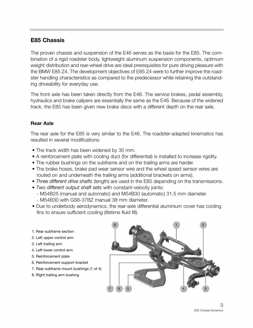
The rear axle for the E85 is very similar to the E46. The roadster-adapted kinematics hasresulted in several modifications:
• The track width has been widened by 30 mm.• A reinforcement plate with cooling duct (for differential) is installed to increase rigidity.• The rubber bushings on the subframe and on the trailing arms are harder.• The brake hoses, brake pad wear sensor wire and the wheel speed sensor wires are
routed on and underneath the trailing arms (additional brackets on arms).• Three different drive shafts (length) are used in the E85 depending on the transmissions. • Two different output shaft sets with constant-velocity joints:
- M54B25 (manual and automatic) and M54B30 (automatic) 31.5 mm diameter.- M54B30 with GS6-37BZ manual 38 mm diameter.
• Due to underbody aerodynamics, the rear-axle differential aluminium cover has cooling fins to ensure sufficient cooling (lifetime fluid fill).
1. Rear subframe section
2. Left upper control arm
3. Left trailing arm
4. Left lower control arm
5. Reinforcement plate
6. Reinforcement support bracket
7. Rear subframe mount bushings (1 of 4)
8. Right trailing arm bushing
4E85 Chassis Dynamics
Springs and Dampers
The spring/damper set is similar to the E46.
• Front axle: spring struts with coil springs and gas-pressure dampers.
• Rear axle: barrel springs and gas-pressure dampers.
• Ride level is 10 mm lower compared with the E46.
• Compared with the E85 standard suspension, the ride level of the sports suspension (when available) is a further 15 mm lower.
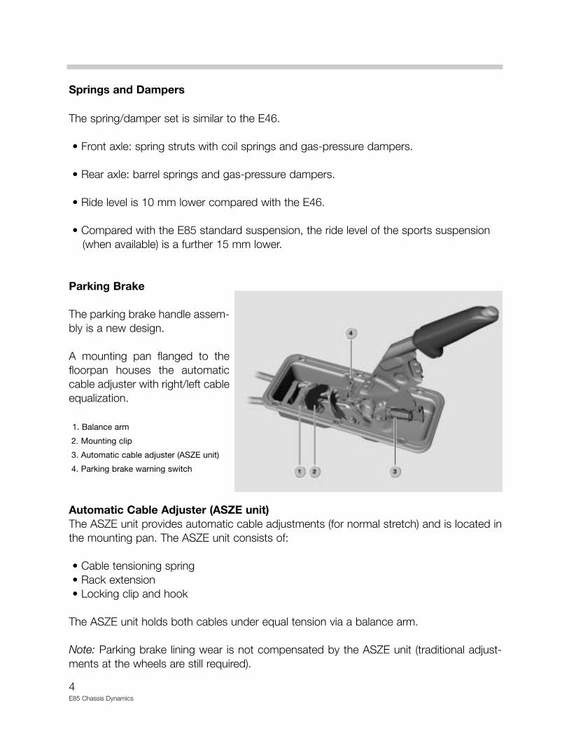
Parking Brake
The parking brake handle assem-bly is a new design.
A mounting pan flanged to thefloorpan houses the automaticcable adjuster with right/left cableequalization.
1. Balance arm
2. Mounting clip
3. Automatic cable adjuster (ASZE unit)
4. Parking brake warning switch
Automatic Cable Adjuster (ASZE unit)The ASZE unit provides automatic cable adjustments (for normal stretch) and is located inthe mounting pan. The ASZE unit consists of:
• Cable tensioning spring• Rack extension• Locking clip and hook
The ASZE unit holds both cables under equal tension via a balance arm.
Note: Parking brake lining wear is not compensated by the ASZE unit (traditional adjust-ments at the wheels are still required).
5E85 Chassis Dynamics
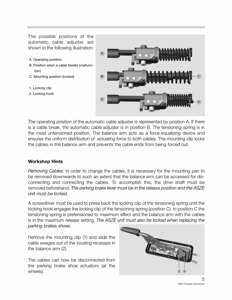
The possible positions of theautomatic cable adjuster areshown in the following illustration:
A. Operating position
B. Position when a cable breaks (malfunc-
tion)
C. Mounting position (locked)
1. Locking clip
2. Locking hook
The operating position of the automatic cable adjuster is represented by position A. If thereis a cable break, the automatic cable adjuster is in position B. The tensioning spring is inthe most untensioned position. The balance arm acts as a force-equalizing device andensures the uniform distribution of actuating force to both cables. The mounting clip locksthe cables in the balance arm and prevents the cable ends from being forced out.
Workshop Hints
Removing Cables: In order to change the cables, it is necessary for the mounting pan tobe removed downwards to such an extent that the balance arm can be accessed for dis-connecting and connecting the cables. To accomplish this, the drive shaft must beremoved beforehand. The parking brake lever must be in the release position and the ASZEunit must be locked.
A screwdriver must be used to press back the locking clip of the tensioning spring until thelocking hook engages the locking clip of the tensioning spring (position C). In position C thetensioning spring is pretensioned to maximum effect and the balance arm with the cablesis in the maximum release setting. The ASZE unit must also be locked when replacing theparking brakes shoes.
Remove the mounting clip (1) and slide thecable sweges out of the locating recesses inthe balance arm (2).
The cables can now be disconnected fromthe parking brake shoe actuators (at thewheels).
6E85 Chassis Dynamics
Installing Cables: The parking brake lever must be in the "released" position. The cables donot automatically feed themselves into the balance arm on insertion, but must be guidedwith a screwdriver into the correct position.
Attach the mounting clip (1) to secure the cables in the balance arm (2). The mounting pancan be resecured in position. Connect the cables to the parking brake actuators (at thewheels).
Adjustment: The basic clearance of the parking brake shoes is adjusted at the adjustmentwheel (screw) of the parking brake shoes in the traditional manner. The parking brake isautomatically adjusted when the ASZE unit is unlocked. The pretension of the tensioningspring is relieved at the automatic cable adjuster with a screwdriver by moving the lockinghook out of the locking clip.
The parking brake lever can be tightened in a low notch setting (pull upwards - 1 click) forthis procedure. This makes it easier to access the locking hook. When the locking hook isreleased, the automatic cable adjuster returns to the operating position. The cables areretensioned.
Notes:

7E85 Chassis Dynamics
Electric Power Steering (EPS)
Purpose of the System
With a conventional power assisted (hydraulic) steering system, a belt driven pump pro-vides pressure to the control valve which is integral in the power steering rack. When thesteering shaft is turned, the control valve provides pressure to assist (decrease effort) inturning the steering gear.
On some BMW vehicles, this control pressure is reduced by increasing vehicle speed viaan electronically controlled bleed off valve (Servotronic). However; hydraulic power assitedsteering systems utilize a reservoir, hydraulic fluid, pump, hoses/lines, cooler, hydraulicvalve/steering rack, Servotronic valve, purpose built steering shaft and column.
Electric Power Steering (EPS) is used for the first time by BMW in the E85. It provides thetypical BMW power assisted steering characteristics and “feel”. The EPS is a very direct,sporty steering element with a change-over between normal and “Sport” mode by theDynamic Driving Control (Sport) button.
The EPS differs from the conventional hydraulic power assisted steering system by utilizingelectrical/electronic components to provide power assisted steering while retaining a com-plete mechanical connection. The EPS is a "dry system", the hydraulic components and oilare not required.
The programmed EPS control functions areinfluenced by vehicle speed and provide addi-tional benefits regarding steering tuning,absorption adjustments and active steeringreturn characteristics.
The EPS system includes:
1. EPS Control Module 4. Steering Rack 2. EPS Electric Motor 5. Steering Gears 3. Lower Steering Column 6. Steering Angle Sensor
The advantages of EPS are:
• Less maintenance and assembly • Improved driving dynamics • Increased comfort • Increased driving safety • Weight reduction• Increased environmental compatibility • Less power consumption
8E85 Chassis Dynamics
Improved Driving Dynamics: - The EPS Electric Motor provides good power assisted steering control characteristics. - Active return to center. - Switchable steering characteristic (Dynamic Driving Control). - Use of light weight sport steering wheels (1kg less than other steering wheels).
Increased Driving Comfort: - Decouples unnessesary steering oscillations (from road disturbances) while maintaining
relevant road feel information (different road conditions) to the driver. - Speed dependent steering assist force (parking vs. high speed driving).
Increased Driving Safety: - EPS provides a direct mechanical connection to the steering gear, conveying direct road
feel.- Speed dependent steering actively absorbs left/right roll.
Increased Environmental Compatibility: - Reduced fuel and engine power consumption - Leak free "dry system"
System Components
The EPS system is divided into 3 component groups:
• Upper steering column assembly • Steering gear with rack• Lower steering spindle
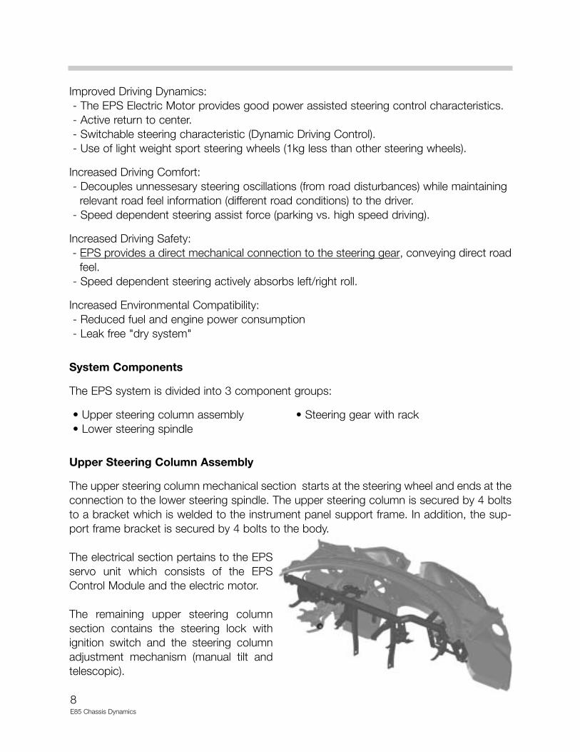
Upper Steering Column Assembly
The upper steering column mechanical section starts at the steering wheel and ends at theconnection to the lower steering spindle. The upper steering column is secured by 4 boltsto a bracket which is welded to the instrument panel support frame. In addition, the sup-port frame bracket is secured by 4 bolts to the body.
The electrical section pertains to the EPSservo unit which consists of the EPSControl Module and the electric motor.
The remaining upper steering columnsection contains the steering lock withignition switch and the steering columnadjustment mechanism (manual tilt andtelescopic).
9E85 Chassis Dynamics
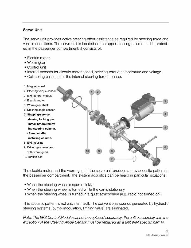
Servo Unit
The servo unit provides active steering-effort assistance as required by steering force andvehicle conditions. The servo unit is located on the upper steering column and is protect-ed in the passenger compartment, it consists of:
• Electric motor• Worm gear• Control unit• Internal sensors for electric motor speed, steering torque, temperature and voltage.• Coil-spring cassette for the internal steering torque sensor.
1. Magnet wheel
2. Steering torque sensor
3. EPS control module
4. Electric motor
5. Worm gear shaft
6. Steering angle sensor
7. Shipping/service
steering locking pin
- Install before remov-
ing steering column.
- Remove after
installing column.
8. EPS housing
9. Driven gear (meshes
with worm gear)
10. Torsion bar
The electric motor and the worm gear in the servo unit produce a new acoustic pattern inthe passenger compartment. The system acoustics can be heard in particular situations:
• When the steering wheel is spun quickly• When the steering wheel is turned while the car is stationary• When the steering wheel is turned in a quiet atmosphere (e.g. radio not turned on)
This acoustic pattern is not a system fault. The conventional sounds generated by hydraulicsteering systems (pump modulation, limiting valve) are eliminated.
Note: The EPS Control Module cannot be replaced separately, the entire assembly with theexception of the Steering Angle Sensor must be replaced as a unit (VIN specific part #).
10E85 Chassis Dynamics
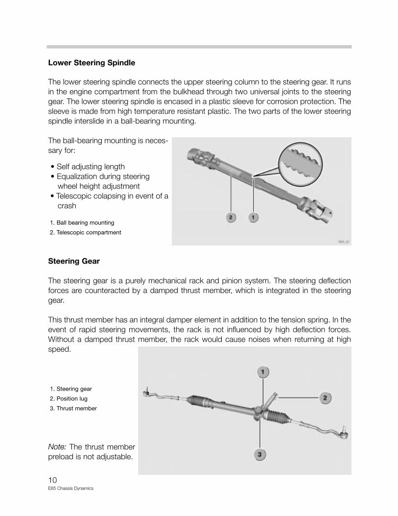
Lower Steering Spindle
The lower steering spindle connects the upper steering column to the steering gear. It runsin the engine compartment from the bulkhead through two universal joints to the steeringgear. The lower steering spindle is encased in a plastic sleeve for corrosion protection. Thesleeve is made from high temperature resistant plastic. The two parts of the lower steeringspindle interslide in a ball-bearing mounting.
The ball-bearing mounting is neces-sary for:
• Self adjusting length• Equalization during steering
wheel height adjustment• Telescopic colapsing in event of a
crash
1. Ball bearing mounting
2. Telescopic compartment
Steering Gear
The steering gear is a purely mechanical rack and pinion system. The steering deflectionforces are counteracted by a damped thrust member, which is integrated in the steeringgear.
This thrust member has an integral damper element in addition to the tension spring. In theevent of rapid steering movements, the rack is not influenced by high deflection forces.Without a damped thrust member, the rack would cause noises when returning at highspeed.
1. Steering gear
2. Position lug
3. Thrust member
Note: The thrust memberpreload is not adjustable.
11E85 Chassis Dynamics
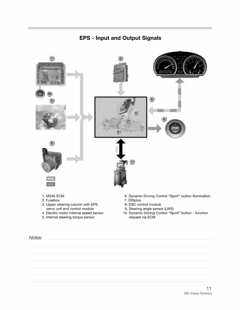
EPS - Input and Output Signals
1. MS45 ECM 6. Dynamic Driving Control “Sport” button illumination2. Fusebox 7. DISplus3. Upper steering column with EPS 8. DSC control module
servo unit and control module 9. Steering angle sensor (LWS)4. Electric motor internal speed sensor 10. Dynamic Driving Control “Sport” button - function 5. Internal steering torque sensor request via ECM
Notes:
12E85 Chassis Dynamics
Principle of Operation
EPS controls servo assistance for steering. In addition to the measuring the driver’s steer-ing torque, the EPS Control Module also monitors further inputs such as:
• Vehicle speed • Dynamic Driving Control (Sport) button• Steering angle velocity • Internal system temperature• Steering angle
The EPS calculates an assistance setpoint. The electric motor is activated via the integrat-ed power electronics and the torque is transmitted through the worm gear to the drivengear (attached to the steering column output shaft).
The Servotronic function (vehicle speed dependent steering assistance) is also integrated.The corresponding assistance and damping characteristics are stored in the EPS ControlModule. The required assistance torque is gradually increased when the engine is startedand reduced (with a delay) when the engine is switched off.
Steering Torque Measurement
The driver’s steering torque is measured by a steering torque sensor integrated in the servounit. The function is based on the magnetoresistive principle, these sensors are curentlyused in BMWs include wheel speed sensors (DSC III MK60) and Valvetronic position sen-sors (E65 - N62 engine). The magnetoresistive elements resistance changes as a functionof the magnetic field acting on them.
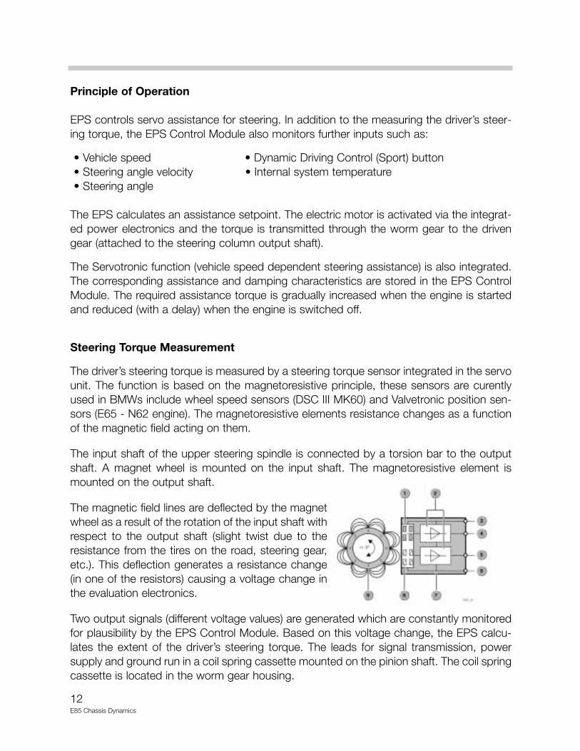
The input shaft of the upper steering spindle is connected by a torsion bar to the outputshaft. A magnet wheel is mounted on the input shaft. The magnetoresistive element ismounted on the output shaft.
The magnetic field lines are deflected by the magnetwheel as a result of the rotation of the input shaft withrespect to the output shaft (slight twist due to theresistance from the tires on the road, steering gear,etc.). This deflection generates a resistance change(in one of the resistors) causing a voltage change inthe evaluation electronics.
Two output signals (different voltage values) are generated which are constantly monitoredfor plausibility by the EPS Control Module. Based on this voltage change, the EPS calcu-lates the extent of the driver’s steering torque. The leads for signal transmission, powersupply and ground run in a coil spring cassette mounted on the pinion shaft. The coil springcassette is located in the worm gear housing.
13E85 Chassis Dynamics
Steering Angle Measurement
To be able to perform active steering wheel resetting (return to center), the EPS ControlModule requires the following:
• Steering wheel center position• Present steering wheel angle
The above information is input to the EPS ControlModule by the steering angle sensor (LWS), in additionto the DSC system requirement. The steering anglesensor is located on the lower steering column in thepassenger compartment.
Note: The steering angle sensor must be calibrated(like the E46 DSC). 4. Steering angle sensor (LWS)
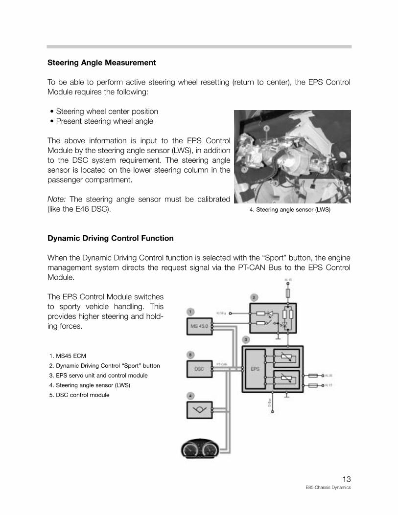
Dynamic Driving Control Function
When the Dynamic Driving Control function is selected with the “Sport” button, the enginemanagement system directs the request signal via the PT-CAN Bus to the EPS ControlModule.
The EPS Control Module switchesto sporty vehicle handling. Thisprovides higher steering and hold-ing forces.
1. MS45 ECM
2. Dynamic Driving Control “Sport” button
3. EPS servo unit and control module
4. Steering angle sensor (LWS)
5. DSC control module
14E85 Chassis Dynamics
Indicator Light
The instrument cluster contains an indicator light for the EPS system. This light alerts thedriver to significantly reduced steering effort assistance or to a complete shutdown of assis-tance. This may be caused by:
• Fault in the EPS Control Module or an associated control module (DSC, ECM).
• Undervoltage/overvoltage
• Overloading of EPS
Workshop Hints
Servo Assistance Reduction or Shutdown
When the EPS system is overloaded, it protects itself by reducing or shutting down servoassistance while retaining a complete mechanical connection for steering. The drivernotices the increased steering torque and receives a visual signal from the indicator light.
The following causes will implement protective measures:
• Servo assistance is reduced/shut down if a fault relevant to EPS is detected in an asso- ciated Control Module/sensors (ECM, DSC Control Module, Steering Angle Sensor). A fault code is stored and the indicator light in the instrument cluster illuminates in the event of complete assistance shutdown.
• Power assisted steering is reduced as EPS internal temperature increases (due to over-loading). When reduction of the power is not sufficient to cool the system down, servo assistance is reduced down to zero. A fault is stored and the indicator light in the instru-ment cluster illuminates. When the temperature cools down, servo assistance returns within 2 seconds to the present requested value.
• In the event of overvoltage (> 17 V), servo assistance shuts down immediately to protect the output transistors. A fault is stored and the indicator light in the instrument cluster illuminates. When the voltage drops (< 16 V), servo assistance returns within 2 seconds to the present requested value.
15E85 Chassis Dynamics
• If an undervoltage (< 9 V) is detected, servo assistance is immediately reduced down to 0. A fault is stored and the indicator light illuiminates in the event of complete assistance shutdown. When the voltage returns to a level > 10 V, servo assistance increases within 2 seconds to the requested value. In all cases, the indicator light goes out when the fault is no longer present.
Default Structure
Default 1 - Complete shutdown (Control Module, under/over voltage, no assist.
Default 2 - When the steering is held in left/right lock position > 40 seconds, power is reduced by 50% (due to increasing internal temperature).
Default 3 - Vehicle speed signal is missing, Servotronic feature is deactivated.
Default 4 - When the Steering Angle Sensor (LWS) input is defective, active return center-ing is deactivated.
Working on Steering Column
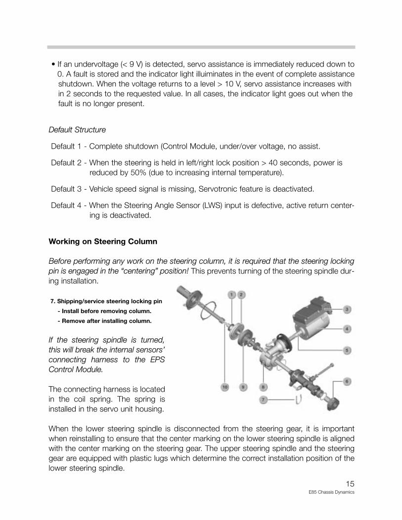
Before performing any work on the steering column, it is required that the steering lockingpin is engaged in the “centering” position! This prevents turning of the steering spindle dur-ing installation.
7. Shipping/service steering locking pin
- Install before removing column.
- Remove after installing column.
If the steering spindle is turned,this will break the internal sensors’connecting harness to the EPSControl Module.
The connecting harness is locatedin the coil spring. The spring isinstalled in the servo unit housing.
When the lower steering spindle is disconnected from the steering gear, it is importantwhen reinstalling to ensure that the center marking on the lower steering spindle is alignedwith the center marking on the steering gear. The upper steering spindle and the steeringgear are equipped with plastic lugs which determine the correct installation position of thelower steering spindle.
16E85 Chassis Dynamics
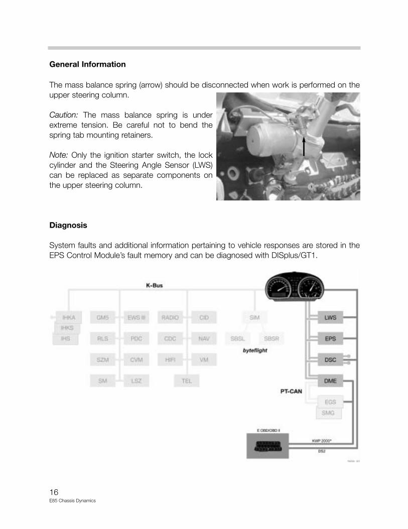
General Information
The mass balance spring (arrow) should be disconnected when work is performed on theupper steering column.
Caution: The mass balance spring is underextreme tension. Be careful not to bend thespring tab mounting retainers.
Note: Only the ignition starter switch, the lockcylinder and the Steering Angle Sensor (LWS)can be replaced as separate components onthe upper steering column.
Diagnosis
System faults and additional information pertaining to vehicle responses are stored in theEPS Control Module’s fault memory and can be diagnosed with DISplus/GT1.
17E85 Chassis Dynamics
Dynamic Stability Control
Purpose of the System
The Dynamic Stability Control system (DSC MK 60) currently in the E46 is carried over tothe E85. In addition to the ABS, ASC and CBC functions, the DSC system incorporates afurther function in the E85, Dynamic Traction Control (DTC). The DTC function can be acti-vated with the DSC button and provides two subfunctions:
• Sports tuning of the Automatic Stability Control (ASC) + Dynamic Stability Control (DSC)• Improved traction, particularly on ground surfaces with a low coefficient of friction
All other functions have essentially remained the same. A "DTC" indicator light illuminatesin the instrument cluster when the DTC function is activated. The DSC warning light in theinstrument cluster flashes when intervention is necessary and takes priority over all otherfunctions (as in current E46 vehicles).
In certain situations (i.e. accelerating on an uphill gradient on a snow covered road), the pre-vious ASC function provided brake intervention at the spinning wheel and extremelyreduced the engine output. Although the vehicle remained extremely stable, minimalpropulsion was available.
DTC achieves maximum possible traction essentially by expanded ASC and DSC controlthresholds. Compared to the ASC/DSC function, DTC mode allows a little more "drift" atlow speeds and transverse acceleration (increased rear wheel spin is permissible up to aspeed of approx. 45 mph). This allows the engine power output to remain without anextreme reduction of power, improving propulsion.
On approaching higher speeds and transverse acceleration (measured by the yaw rate sen-sor), the DTC function acts more and more like the "normal" ASC and DSC function andthe slip thresholds are reduced back to a conservative mode for stability reasons.
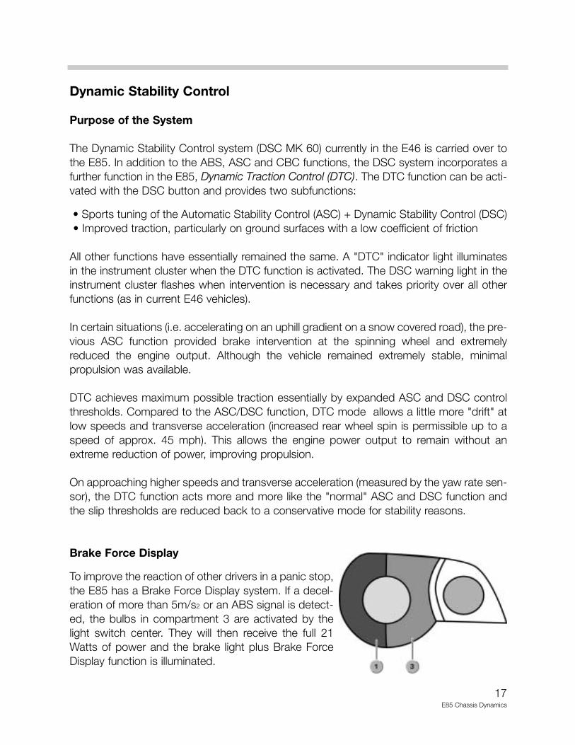
Brake Force Display
To improve the reaction of other drivers in a panic stop,the E85 has a Brake Force Display system. If a decel-eration of more than 5m/s2 or an ABS signal is detect-ed, the bulbs in compartment 3 are activated by thelight switch center. They will then receive the full 21Watts of power and the brake light plus Brake ForceDisplay function is illuminated.

18E85 Chassis Dynamics
DSC - Input and Output Signals
1. Wheel speed sensors 8. RPA (Tire Deflation Warning) button2. Power distribution box (KL30 and KL15) 9. DSC button3. MS45 ECM 10. Steering angle sensor (LWS)4. Instrument cluster 11. Brake light switch5. Navigation computer 12. DSC yaw rate sensor6. Private CAN (DSC-CAN High and 13. Handbrake switch
DSC-CAN Low) between DSC 14. Sensors: 2 pressure sensors inyaw rate sensor and DSC module master brake cylinder and one
7. DISplus/GT1 brake fluid sensor
19E85 Chassis Dynamics
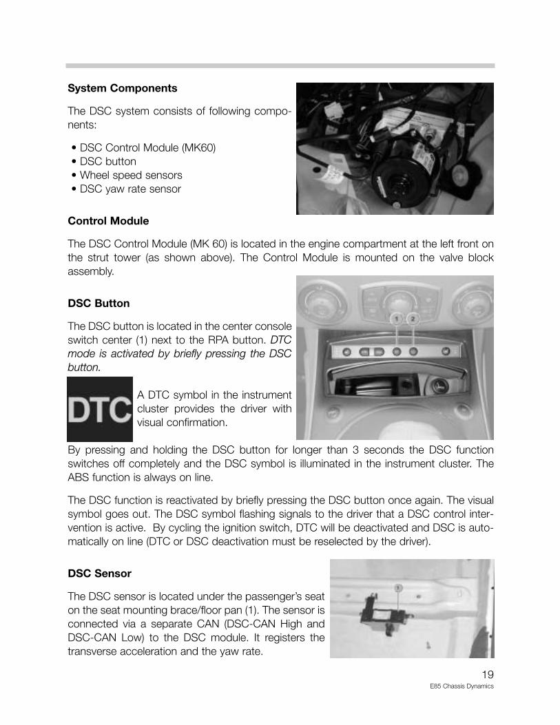
System Components
The DSC system consists of following compo-nents:
• DSC Control Module (MK60)• DSC button• Wheel speed sensors• DSC yaw rate sensor
Control Module
The DSC Control Module (MK 60) is located in the engine compartment at the left front onthe strut tower (as shown above). The Control Module is mounted on the valve blockassembly.
DSC Button
The DSC button is located in the center consoleswitch center (1) next to the RPA button. DTCmode is activated by briefly pressing the DSCbutton.
A DTC symbol in the instrumentcluster provides the driver withvisual confirmation.
By pressing and holding the DSC button for longer than 3 seconds the DSC functionswitches off completely and the DSC symbol is illuminated in the instrument cluster. TheABS function is always on line.
The DSC function is reactivated by briefly pressing the DSC button once again. The visualsymbol goes out. The DSC symbol flashing signals to the driver that a DSC control inter-vention is active. By cycling the ignition switch, DTC will be deactivated and DSC is auto-matically on line (DTC or DSC deactivation must be reselected by the driver).
DSC Sensor
The DSC sensor is located under the passenger’s seaton the seat mounting brace/floor pan (1). The sensor isconnected via a separate CAN (DSC-CAN High andDSC-CAN Low) to the DSC module. It registers thetransverse acceleration and the yaw rate.
20E85 Chassis Dynamics
E85 Run Flat Tire (RFT) Technology
Purpose of the System
BMW Run Flat Tire (RFT) Technology which was first introduced on the Z8, is standard onthe E85 (Z4). RFT technology offers large advantages to the customer in dynamic stabilitywith slow or sudden air pressure loss and Deflation Warning. In addition, the spare wheeland jacking equipment in the trunk is deleted which provides additional storage space.
A tire with back up running ability (RFT) will be differentiated froma non-run flat tire by the encircled letter designation on the side-wall (for example: RSC - Runflat System Component).
Principle of Operation
If slow or sudden inflation pressure loss occurs in a RFT, it is still mobile because of theadditional high temperature rubber reinforcements that strengthen the side wall.
These reinforcements prevent side wall damage when the tire is deflated and also providessupport during extreme loads (even when negotiating curves). In addition, the special RFTwheel (rim) grips the tire for sufficient steering, braking and accelerating power.
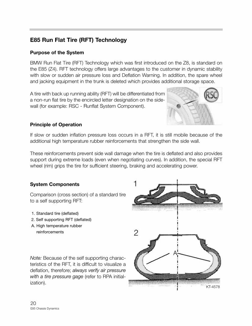
System Components
Comparison (cross section) of a standard tireto a self supporting RFT:
1. Standard tire (deflated)
2. Self supporting RFT (deflated)
A. High temperature rubber
reinforcements
Note: Because of the self supporting charac-teristics of the RFT, it is difficult to visualize adeflation, therefore; always verify air pressurewith a tire pressure gage (refer to RPA initial-ization).
KT-4578
21E85 Chassis Dynamics
Note:- With a sudden inflation pressure loss the vehicle can be driven with a maximum
speed of 50 mph for a maximum distance of approx. 100 miles.
- With a slow inflation pressure loss the vehicle can be driven with a maximum speed of 50 mph for a maximum distance of approx. 1200 miles.
- A winter profile RFT will also be offered.
- In an extreme case, standard tires can be temporarily substitued on the samewheel (rim) if RFT is not available.
Tire Deflation Warning (RPA)
When a slow inflation pressure loss is present, it is more difficult for the driver to recognizethe gradually increasing “spongy” handling of the vehicle (this constitutes approx. 80% offlat tire cases). The condition is more dificult to detect with RFT because of the increasedsidewall rigidity. The Tire Deflation Warning (RPA) monitors tire deflation and will alert thedriver.
Principle of Operation
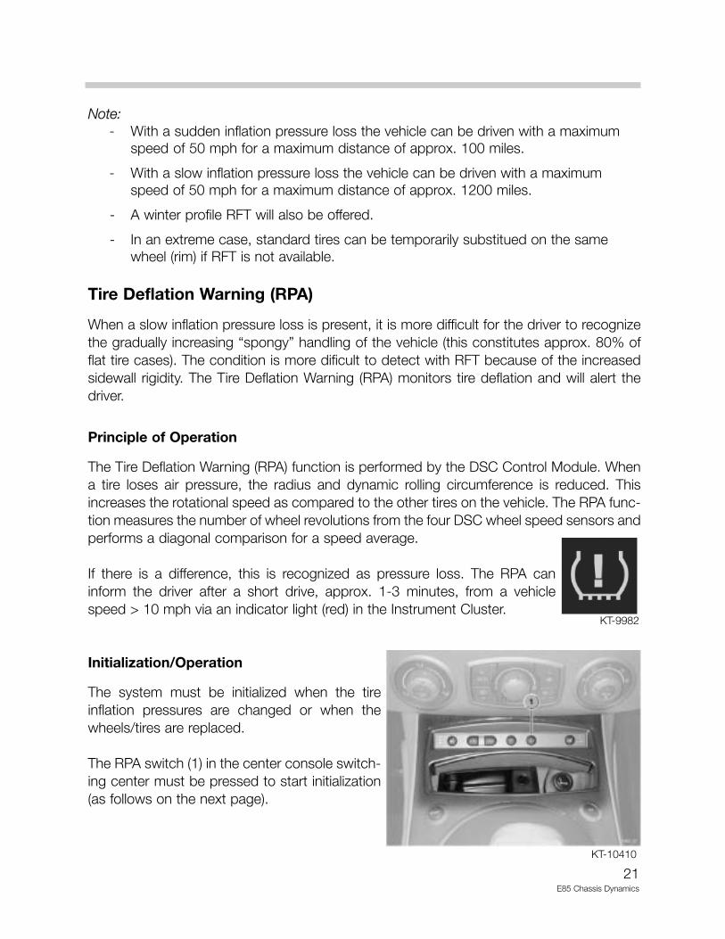
The Tire Deflation Warning (RPA) function is performed by the DSC Control Module. Whena tire loses air pressure, the radius and dynamic rolling circumference is reduced. Thisincreases the rotational speed as compared to the other tires on the vehicle. The RPA func-tion measures the number of wheel revolutions from the four DSC wheel speed sensors andperforms a diagonal comparison for a speed average.
If there is a difference, this is recognized as pressure loss. The RPA caninform the driver after a short drive, approx. 1-3 minutes, from a vehiclespeed > 10 mph via an indicator light (red) in the Instrument Cluster.
Initialization/Operation
The system must be initialized when the tireinflation pressures are changed or when thewheels/tires are replaced.
The RPA switch (1) in the center console switch-ing center must be pressed to start initialization(as follows on the next page).
KT-9982
KT-10410
22E85 Chassis Dynamics
With KL15 “on”, press the RPA switch until the RPA indicator light in theInstrument Cluster illuminates in “yellow”.
After a a short drive (approx. 1-3 minutes), from a vehicle speed > 10 mph,the system learns the new wheel speed sensor reference values and the RPAindicator light (yellow) goes out.
When an inflation pressure loss is determined, the RPA indicator light illuminates in “red”.The driver is informed of a RPA system failure by the “yellow” illuminated RPA indicator light.
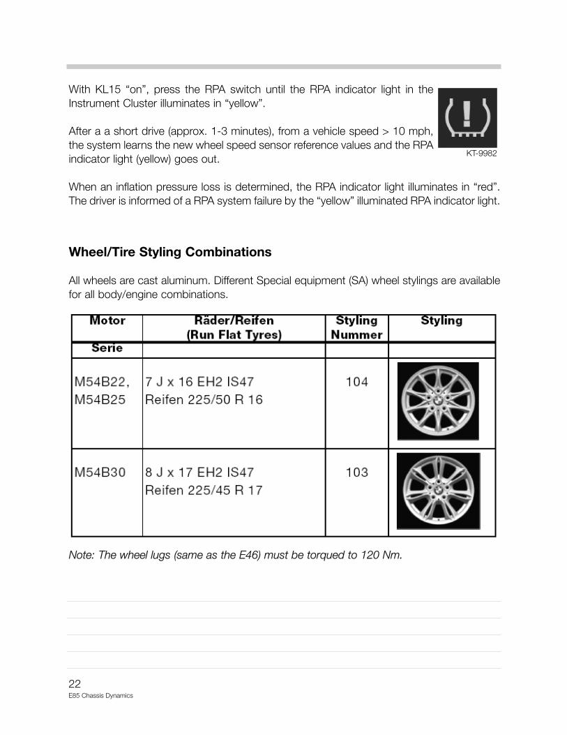
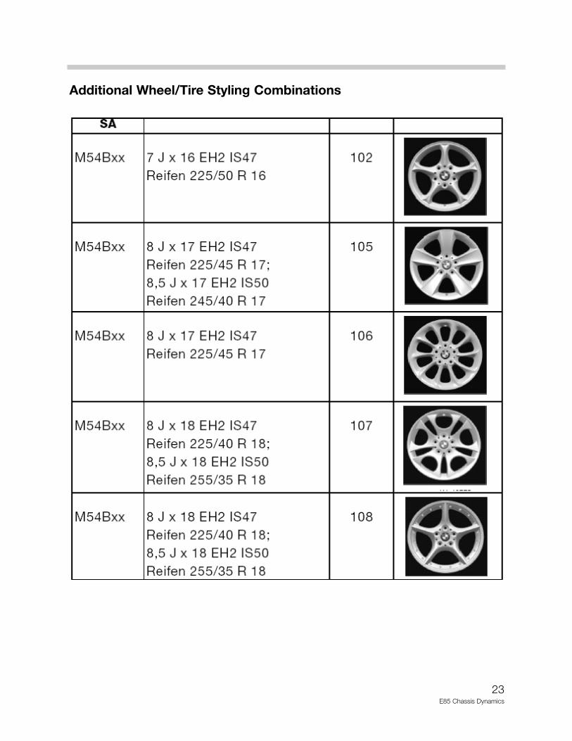
Wheel/Tire Styling Combinations
All wheels are cast aluminum. Different Special equipment (SA) wheel stylings are availablefor all body/engine combinations.
Note: The wheel lugs (same as the E46) must be torqued to 120 Nm.
KT-9982
23E85 Chassis Dynamics
Additional Wheel/Tire Styling Combinations
24Running Gear/E52
Review Questions
1. What is the only reliable method to verify the correct inflation pressure in a RFT?
2. List the RPA Initialization procedure:
3. The ASZE unit must be in the “locked” position for what two service procedures?
4. How does the “Sport” button affect the EPS system?
5. What must be installed in the EPS column before removal and be removed after instal-lation?
6. How is DTC activated?
7. When the EPS indicator light is illuminated, what does this indicate?
What could be the causes?