Embed Size (px)
Citation preview


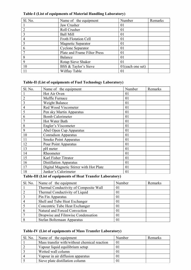
Table-I (List of equipments of Material Handling Laboratory)
Sl. No. Name of the equipment Number Remarks1 Jaw Crusher 012 Roll Crusher 013 Ball Mill 014 Froth Flotation Cell 015 Magnetic Separator 016 Cyclone Separator 017 Plate and Frame Filter Press 018 Balance 019 Rotap Sieve Shaker 0110 BSS & Taylor’s Sieve 01(each one set)11 Wilflay Table 01
Table-II (List of equipments of Fuel Technology Laboratory)
Sl. No. Name of the equipment Number Remarks1 Hot Air Oven 012 Muffle Furnace 013 Weight Balance 014 Red Wood Viscometer 015 Pen sky Martin Apparatus 016 Bomb Calorimeter 017 Hot Water Bath 018 Engler’s Viscometer 019 Abel Open Cup Apparatus 0110 Conradson Apparatus 0111 Smoke Point Apparatus 0112 Pour Point Apparatus 0113 pH meter 0114 Rheometer 0115 Karl Fisher Titrator 0116 Distillation Apparatus 0117 Digital Magnetic Stirrer with Hot Plate 0118 Junker’s Calorimeter 01Table-III (List of equipments of Heat Transfer Laboratory)
Sl. No. Name of the equipment Number Remarks1 Thermal Conductivity of Composite Wall 012 Thermal Conductivity of Liquid 013 Pin Fin Apparatus 014 Shell and Tube Heat Exchanger 015 Concentric Tube Heat Exchanger 016 Natural and Forced Convection 017 Dropwise and Filmwise Condensation 018 Stefan Boltzmaan Apparatus 01
Table-IV (List of equipments of Mass Transfer Laboratory)
Sl. No. Name of the equipment Number Remarks1 Mass transfer with/without chemical reaction 012 Vapour liquid equilibrium setup 013 Wetted wall column 014 Vapour in air diffusion apparatus 015 Sieve plate distillation column 01

6 Simple Distillation apparatus 017 Steam distillation apparatus 01

Table-V (List of equipments of Chemical Reaction Engineering Laboratory)
Sl. No. Name of the equipment Number Remarks1 Batch reactor 012 CSTR in series 013 PFR( Straight tube type) 014 CSTR 015 Isothermal batch reactor 016 Isothermal CSTR 017 Isothermal Plug flow tubular reactor(Coiled tube type) 01Table-VI (List of equipments of Process Control and Instrumentation Laboratory)
Sl. No. Name of the equipment Number Remarks1 Flow control trainer setup 012 Control valve characteristics setup 013 Interacting and non-interacting 01Table-VII (List of equipments of Computer Aided design Laboratory)
Sl. No. Name of the equipment Number Remarks1 Aspen hysis software 01Table-VIII (List of equipments of Mass Transfer design Laboratory and Heat transfer
design Laboratory)
Sl. No. Name of the equipment Number Remarks1 Matlab software 01
Table-IX (List of equipments of Chemical Engg. Thermodynamics Laboratory)
Sl. No. Name of the equipment Number Remarks1 Humidification and dehumidification set up 012 Computer controlled vapour-liquid equilibrium set up 013 Air conditioning test 014 Water to water heat pump 01
EQUIPMENT SPECIFICATIONS
MATERIAL HANDLING LAB.S.NO Name of the Equipment/Setup Technical Specifications
1 Sieve Set(2 SETS) As per ASTM E 11-09 standard specification.
Standard test sieves of 200 mm (8 in) dia. and 50

mm (2 in) height with brass sieves with the
following standard openings.
British std. Indian std. Taylor
std.
4 4.000 4
8 2.000 8
16 1.000 16
22 0.710 22
30 0.500 30
52 0.300 52
72 0.212 72
85 0.180 85
100 0.150 100
150 0.106 150
200 0.075 200
300 0.053 300
350 0.045 350
400 0.037 400
Receiver pan+ Lid -2 Sieve shaker Sieve assembly: Compatible to sieves of 10-20 mm
dia (5-6 sieves).
Drive: By FHP motor.
• Control panel should consist of Standard
make on-off switch, mains indicator.
• The whole set up should be well designed
and arranged on a rigid structure.
• Special arrangement for settling time for
shaking.
• An English instruction manual consisting of
experimental procedure,
Block diagrams should be provided along
with apparatus.3 Jaw crusher Jaws - Manganese Steel
Jaw Size – 6’’× 8”
Feed Size – 3-5”
Product Size – 10mm -20mm Motor Capacity = 5
HP, 3 phase Capacity 300 kg/h.
• An English instruction manual consisting of

experimental procedure,
Block diagrams should be provided along
with apparatus.
• The whole set up should be well designed
and arranged on a rigid structure
4 Roll crusher Rolls Material Chilled steel, Dia100-200mm,
width 50-100mm approx.
Max feed Size 6-10mm
Product Size- 1-2mm
Feed hopper: Suitable capacity.
Drive: 2HP motor coupled with reduction gear box.
• Control panel should consist of electronic
energy meter, starter and an MCB.
• The whole set up should be well designed
and arranged on a rigid structure.
• An English instruction manual consisting
of experimental procedure,
block diagrams should be provided along
with apparatus.5 Ball Mill Material MS, Dia 250-275mm,
Length 300-350 mm, thickness 4-5 mm.
Discharge suite: Suitable size.
Feed size 4-6mm approx.
Product size: 200 mesh approx. Drive: 1/2HP
motor coupled with reduction gear box.
Product receiver: Material SS of suitable size.
Revolution counter: Mechanical type.
• The whole set up should be well designed
and arranged on a rigid structure.
• An English instruction manual consisting
of experimental procedure,
block diagrams should be provided along
with apparatus.6 Plate and Frame filter press No of frames: 4-6
No of plates: 5-7
Size: 200 mm×200 mm
Material: Acrylic

Filter medium :Filter cloth
Filtrate collecting tray: Material SS suitable size.
Slurry feed tank: Material SS capacity 20-40 Ltrs.
Slurry tank agitator: SS impeller with SS shaft
coupled to motor and reduction gear box.
Slurry feed pump: Gear pump with motor.
Piping system: GI and PVC.
Filtration rate measurement: Using measuring tank,
Material SS.
Pressure measurement: Bourden type pressure
measurement.
Overhead water tank: Material SS, Capacity 20-25
Ltrs.
• Control panel should consist of Standard
make on-off switch, mains indicator.
• The whole set up should be well designed
and arranged on a rigid structure.
• An English instruction manual consisting of
experimental procedure,
block diagrams should be provided along
with apparatus.7 Froth Flotation Cell Floatation chamber: Material SS, compatable
capacity
Agitator: Stainless steel impeller with SS shaft
coupled to motor.
Diffuser: Material SS holding the impeller.
Froth collecting tank: Material SS, Capacity 10-20
Ltrs
• Control panel should consist of Standard
make on-off switch, mains indicator.
• The whole set up should be well designed
and arranged on a rigid structure.
• An English instruction manual consisting of
experimental procedure, block diagrams
should be provided along with apparatus.8. Wilfley table Size: 1’ width x 4’ length
Capacity: 50 to 250 kg/hr
RPM: 250 to 350

Amplitude: 5 mm to 13 mm
Motor:0.75 hp/415 v/3 ph/50 cycles/1440
rpm/TEFC (Totally enclosed fan-cooled)9 Magnetic separator Belts: Width 100-150 mm, Length 400-500 mm.
Feed hopper: Material SS, suitable capacity
(continuous vibrating).
Drive: Motor with reduction gear box.
Magnets: Permanent magnets kept in a SS
chamber.
Collecting Bins: 2 Nos one for magnetic and other
for non-magnetic material.
• Control panel should consist of Standard
make on-off switch, mains indicator.
• The whole set up should be well designed
and arranged on a rigid structure.
• An English instruction manual consisting of
experimental procedure, block diagrams
should be provided along with apparatus.
10 Balance Weight:0.001-5kg11 Cyclone separator Material Stainless steel, Dia.: 50-100 mm
Solid discharge silo: Material Stainless steel,
suitable capacity with discharge control valve.
Blower: ID Fan blower with 1 HP provided motor.
Air flow measurement: Flow meter with
manometer.
Solids collector: Transparent PVC controller fixed
with cyclone.
Fine dust collector: Bag of nylon cloth fixed on exit
of air.
• Control panel should consist of Standard
make on-off switch, mains indicator.
• The whole set up should be well designed
and arranged on a rigid structure.
• An English instruction manual consisting of
experimental procedure,
Block diagrams should be provided along
with apparatus.

HEAT TRANSFER LAB.
S.NO Name of the setup Technical Specifications1 Thermal
conductivity of
composite wall
1) Slab Size:
a) M.S – 25 cmφ × 25mm thick
b) Bakelite – 25cmφ × 10mm thick
c) Brass – 25cmφ × 10mm thick
2) Nichrome heater wound on mica former and insulator
with control unit capacity 200 watt maximum.
3)Heater control unit – 230 V, 0—2 A single phase
Dimmerstat 1 no
4)Voltmeter – 0 – 250 volts
5) Ammeter – 0 -1 1 amps.
6)Multichannel digital temperature indicator,
Wall thickness Conductivity:
7) M.S = 2.5 cm; 0.46 w/moK
8) Bakelite = 1.0 cm ; 0.12w/moK
9)Brass =1.0 cm; 110w/moK2 Thermal
conductivity of
liquid
1) Main Heater – Mica heater φ 100 mm sandwiched
between plates-300 watts
2)Ring Heater – Mica Ring heater, sandwiched between
plates – 300 watts
3) Top Heater – Mica Heater, sandwiched between plates –
200 Watts
4) Cooling Plates with test liquid cavity
5) Glass wool insulation covers for heater and cooling plate
assembly.
6) Measurements and controls:
• Separate dimmers for heaters, 2 Amp. Capacity: 3
nos.
• Voltmeter and Ammeter for heater input
measurement.
• Voltmeter/Ammeter selector switch.

• Multichannel digital temperature indicator 00c to
2000c with 0.10c least count.3 Pin Fin Apparatus 1) Duct size: 150mm x 100mm. Cross section, 1000mm
long connected to suction side blower.
2)Diameter of the fin:12 mm. O.D, effective length 102
mm with 5 nos. of thermocouples positions along the
length, made of mild steel
3) Fin is screwed in block which is heated by a band heater.
4) No. of thermocouples on fin: 5nos.
5) Temperature indicator: 0 – 300 0C with compensation of
ambient temperature up to 500C.
6) Dimmerstat for heat input control: 0- 230V, 2 Amps.
7) Voltmeter : 0 – 250 V
8) Ammeter: 0 – 1 Amps.4 Shell and Tube Heat
Exchanger
1) Shell 150 NB, 750 mm long provided with end boxes.
2)One end box with divider box
3) 25% cut baffles – 4 nos. In shell side
4) Tube – 4.5 I.D, 6.35 O.D, 750 mm copper with
triangular pitch – 32 nos.
5) Instantaneous water heater, capacity, to supply hot
water.
6) Thermometer for measuring the water temperature.
7) Valves to control hot and cold water flow.5 Concentric Tube
Heat Exchanger
1) Heat exchanger:
a) Inner tube - φ 12.7 mm O.D., φ 11.7 mm I.D. copper
tube.
b) Outer tube - φ 25 mm NB G.I pipe
c) Length of heat exchanger is – 1m.
2) Electric heater – 3 KW capacities to supply hot water.
3) Valves for flow and direction control – 5 nos.
4) Thermometers to measure temperatures – 10 to 110 oC –
4 nos.
5) Measuring flask and stop clock for flow measurement.
6 Natural and Forced
convection
Stainless steel tube, Outer Diameter of the tube (d) = 38-40
mm
2. Length of the tube (L) = 500 mm

3. Duct size = 20cm × 20cm × 1m length
4. Number of the thermocouples = 8
5. Thermocouple number.
6. Temperature Indicator 0-300°C. Multi-channel type
calibrated from iron constantan thermocouples with
compensation of ambient from 0-50°C.
7. Ammeter
8. Voltmeter
9. Dimmerstat7 Drop wise and Film
wise condensation
1. Steam generator of suitable capacity.
2. Copper tubes with - i) Natural finish.
ii) Polished surface finish.
3. Temperature Indicator 0-300°C with chromel alumel
thermocouples.8 Stefan Boltzmaan
Apparatus
1)Hemisphere dia.: 200-400 mm (approx)
2) Jacket dia-250-500 mm (approx)
3) Test disc size -20 mm dia.: x 1.5 mm thickness.
4) Water tank of sufficient capacity with a 1.5kw
immersion heater.
5) Control panel comprises of :-
i) Supply for heater.
ii) Digital temperature Indicator 0-300°C with 0.1 C least
count.
iii) Built in timer for temperature readings at 5 seconds
interval.

FUEL TECHNOLOGY LAB.S.NO Name of the setup Technical Specifications
1 Hot air oven Temp. range up to 300°C, Heating rate of 5-
50°C /min, Accuracy 1°C, Material: Made up
of Stainless steel with 3 shells with provision of
air flow rate or cooling2 Muffle furnace Max. temp. 1200°C , Heating rate 50-100°C
/min, Accuracy 1-5°C, Heating Zone area:
15×30 cms, Controller type :PID
Provision for air cooling, Supported with wheel
stand3 Weight balance Range 0.0001 - 500g , Accuracy:0.001 g
4 Red Wood Viscometer Liquid Flow: 15-2500 sec.
Stain less steel bath with electrical heating
arrangement and controlled by digital
temperature controller com indicator. The
apparatus comprises tap, silver plated steel jet,
and cup cover with precision stainless steel jet,
cup cover, ball valve, thermometer clip, stirrer
and M.S sheet stand with levelling screws. The
temperature should uniformly distributed
throughout the chamber by stirrer. Suitable to
operate on 220 volts, single phase, 50 Hz.5 Pen sky – Martin apparatus ASTMD-93 and IS 1448 (Part I)1270 (P.21)
and IS 1209-1953 method B. Used for finding
out Flash Point above 700 C and below 3000 C.
The Instrument having Oil Test Jet/Gas Test Jet
Flame Device, stirrer with flexible shaft. The
Assembly rests in Air Bath which is covered
with Dome shape metal top. The cup is fitted
with insulated Handle and locking arrangement
near Cup flange. The assemble should be kept
on round shape electric heater with Separate
temp regulator. Suitable for operation on 220
Volts 50 cycles AC Circuits.6 Bomb Calorimeter Complete Digital with 0.01 deg C readout with
one no. of S.S.Bomb with crucible, 3000 cc
jacketed vessel, motorised stirrer, briquette
press, firing Unit, Pressure guage with copper
pipe fitting, magnifying glass, nichrome wire
40 SWG & digital thermometer with printing
facility.


MASS TRANSFER LAB.S.NO Name of the
setup
Technical specifications
1. Mass transfer
with/without
chemical
reaction
Reactor: Material Stainless Steel, Capacity 1-2 Ltrs.(approx)
Water Bath: Material Stainless Steel, Double Wall, Insulated with ceramic
fibre wool.
Heater: Nichrome Wire Heater
Stirrer: Stainless Steel Impeller and shaft couples with DC motor drive for
variable speed.
Temperature Sensors: RTD PT-100 type.
Control panel comprises of RPM Indicator: Digital, Non-contact type
Digital Temp. Controller: 0-199.9° C for hot water tank.
With standard make on/off switch, main indicator & fuse etc.
Peltilizer setup required
• The whole unit should be assembled rigidly on a base plate.
• Whole setup should be well designed and arrangement in a good
quality painted structure.2. Vapour liquid
equilibrium set-
up
Distillation Still:1-2Ltrs capacity, made of stainless steel, insulated by
ceramic wool.
Condenser: Concentric Tube Type.
Heater: Nichrome wire
Cooling Water Tank: Material Stainless Steel, Capacity 15-20Ltrs.
Approx.
Cold Water Circulation Using FHP Pump
Temperature Sensors :RTD PT-100 type
Control panel comprising of
Digital Voltmeter:0-300 Volt.
Dimmerstat: 0-230 V, 2A.
Digital temperature indicator: 0-199.9° C, RTD PT-100 type with multi
channel switch.
Refractometer: Standard make (digital)
• With Standard make on/off switch, Mains Indicator etc.
• The whole set-up should be mounted on a powder coated base
plate.3. Wetted wall
column
Column: Borosilicate Glass, Dia 45-50 mm, Length 1000-2000 mm
(Aprox.)
Water Circulation :FHP pump
Water Tank: Material Stainless Steel, Capacity 15-20 Ltrs.
Heating Chamber : Compatible capacity
Heater: Nichrome wire heater
Rota meter: For Water Flow rate measurement.
Dry & Wet Bulb Temp.: With digital temperature indicator.

Annexure -01
Specifications for Advanced Modular Rheometer
The Rheometer should conform to the following specifications:
1. The Rheometer should have an Asynchronous/synchronous Dynamic Motor having
low inertia allowing fast transient response and excellent high frequency response.
2. The Asynchronous Drag Cup motor/ synchronous motor should be supported by
extremely sensitive 4th generation micro porous carbon air bearings to ensure good low
viscosity measurements for most weakly structured viscoelastic samples. Air Bearing
should be Diffused type Air bearings for eliminating the Wind Mill effect with better
thermal stability.
3. The Rheometer should be equipped with integrated chip for calibration parameters and
High resolution optical encoder with high resolution Digital Signal Processor technology
for precise measurement of the angular deflection.
4. The Rheometer should be equipped with a High Resolution Normal Force for
measurements between -50 N and +50 N allowing axial force measurements during
rotation as well as measurements of axial movement in tension and compression
5. The Rheometer should be enabling for all types of measurements in CS, CR and CD
Mode in Rotation and Oscillation.

6. The housing and frame of the Rheometer should be rigid and stable with maximum
stiffness with optimized force flow i.e. the active forces from the sample and the re-active
forces in the stand should be in one plane to make the measurements with minimum
mechanical interferences. The Rheometer should be with high modularity with open and
enough space for easy sample loading, trimming.
7. The specified values of control parameters for the rheometer should be as follows:
a. Bearing: Air bearing
b. Torque Range : 0.01 µNm to 200 mNm
c. Torque resolution: 0.1 nNm
d. Internal angular resolution: 12 nrad
e. Min. speed: 10-6 rpm (CS mode); 10-7 rpm (CR mode)
f. Max. speed: 3000 rpm
g. Frequency Range : 1 x 10⁻⁵ or lower to 100 Hz
h. Normal Force Range : 0.01 N to 50 N
i. Normal Force Resolution : 0.001 to 0.003 N
j. Lift Speed : 0.05 µm/s to 15 mm/s
k. Gap Resolution : 0.5 µm
8. High Temp. Control Device with a combination of convection and radiant heating to
ensure an even temperature distribution within the chamber. The chamber should have
two halves to allow convenient handling and optimal access to the sample without any
special tools. Each chamber half should be equipped with a window to visualise the
sample during measurement. The Temp. range must be Ambient to 650°C or higher.
Suitable temperature sensor should be provided for handling molten Alluminum alloy.
9. The following measurement cone and plate/ concentric cylinder are desired:
a. Suitable diameter with 1° Cone alongwith Ceramic Shaft
b. Suitable diameter Parallel Plate with Ceramic Shaft
c. Suitable diameter concentric cylinder with Ceramic Shaft
d. Material used should be one of them, mentioned below
Titanium steel/stainless steel/graphite (cost & life of each may be
mentioned separately in the price bid)
10. The rheometer should enable performing the following tests :
a. Controlled Stress – Rotation ( CS )
b. Controlled Rate – Rotation ( CR )
c. CS creep / recovery
d. CD jump / relaxation (CD = Controlled Deformation)
e. CS oscillation
f. CD oscillation
g. Multiwave oscillation

h. Oscillation with superimposed rotation
i. Oscillatory tests (frequency and amplitude sweep )
j. Automatic Maintenance of the gap between the geometries
k. Normal force measurement & control
l. Multi wave test
m. Oscillation data Lissajous plots for data evaluation, display of inertia and
Compliance influence
11. The Rheometer should be interfaced with PC through RS 232 Serial Port, preferably
through TCP/IP Ethernet for fast data acquisition.
12. The rheometer should be driven by user-friendly software that allows Measurements,
Data acquisition, evaluation and report print out with true Multi Tasking also for creating
Methods (Jobs) by using predefined measuring and evaluation elements. The software
should be enable of easy export of data in graphical (pdf etc.) and numerical like ASCII,
Excel etc. The software should be capable of export and import of data in IUPAC XML
format.
13. Software and programming of the tests as follows :
a) Viscosity as a function of Time, Temp. and Shear Rate
b) Yield Stress Measurement
c) Constant Shear Rate Measurement
d) Shear Rate Sweep
e) Oscillation with Stress Control ( Frequency Sweep with Controlled Shear Stress )
The software should be able to show, calculate and plot the standard Rheological
parameters as follows :
- Shear Rate - Steady Shear Viscosity
- Stress - Temp.
- Strain - Time
- Thixotropy - Torque
- Angular Velocity - Angular Frequency
- Yield Stress - Storage Modulus
- Gelation Point - Complex Shear Modulus
- Loss Modulus
14. Suitable Air Compressor, Air Dryer, Computer etc. should be offered as essential utilities
15. Detailed Training for operation of the Rheometer should be provided.
Computer specification
Branded Computer

Intel core i7 processor-3.2 GHz
Ram: 4 G.B
Hard disk: 500 G.B
Monitor: 22 inch TFT
Keyboard, Mouse
O.S – Windows XP/Windows 7 professional with media & License
The vendors shall enclose the following documents with technical bid.
1. Physical evidence i.e. micrograph/graphical results in support of rheological analysis
of Aluminium alloy.
2. P.O. copies of the similar equipment supplied to other academic institutions / R&D
organizations.
3. Assurance that spares will be available for next 7 years after installation of the
machine.
4. Balance sheet/ Financial statement of the manufacturer
5. Details of support service available.
6. Cost of annual maintenance after warranty period should be quoted in the financial
bid.