Embed Size (px)
Citation preview
September 2005
System Level Design with IBM PowerPC ModelsA view of system level design
SLESLE--m3m3

SLE Division, A view of system level design, September 20052
The System-Level ChallengesVerification escapes cost design success
— “There is a 45% chance of committing a logical/functional error when designing an IC/ASIC”Source: Collett International Research 2003 IC/ASIC Design Closure Study
— Can no longer verify large systems at detail level
Functionality convergence challenges validation— Multipurpose devices - video phone, MP3 etc— Functional validation and test is very complex
Multiple IP blocks bring interface problems— Integration, interconnect and interoperability issues
Software dominance of most designs— Need early executable hardware specification
Desire to have physical and power information earlier in the development cycle

SLE Division, A view of system level design, September 20053
“Traditional” Simplified Flow
Co-Verification
Specification(s)Specification(sSpecification(s))
HDL - RTL• Design• Debug• Verification
HDL HDL -- RTLRTL•• DesignDesign•• DebugDebug•• VerificationVerification
Application
BSP (drivers)
ApplicationApplication
BSP (drivers)BSP (drivers)
RTOSRTOS
Software HardwareSoftwareSoftware HardwareHardware
Weak link between specification and implementation
Limited ability to address complexity, assess full range of
tradeoffs

SLE Division, A view of system level design, September 20054
There is a Need for Something New
Paper SpecificationPaper SpecificationPaper Specification
HDL - RTL• Design• Debug• Verification
HDL HDL -- RTLRTL•• DesignDesign•• DebugDebug•• VerificationVerification
Application
BSP (drivers)
ApplicationApplication
BSP (drivers)BSP (drivers)
RTOSRTOSRTOS
Software HardwareSoftwareSoftware HardwareHardware
System ModelSystem ModelSystem Model
More abstract system modelFaster to create and simulate
More “what –if”sConsistent verificationfrom concept to implementation
SLE Division, A view of system level design, September 20055
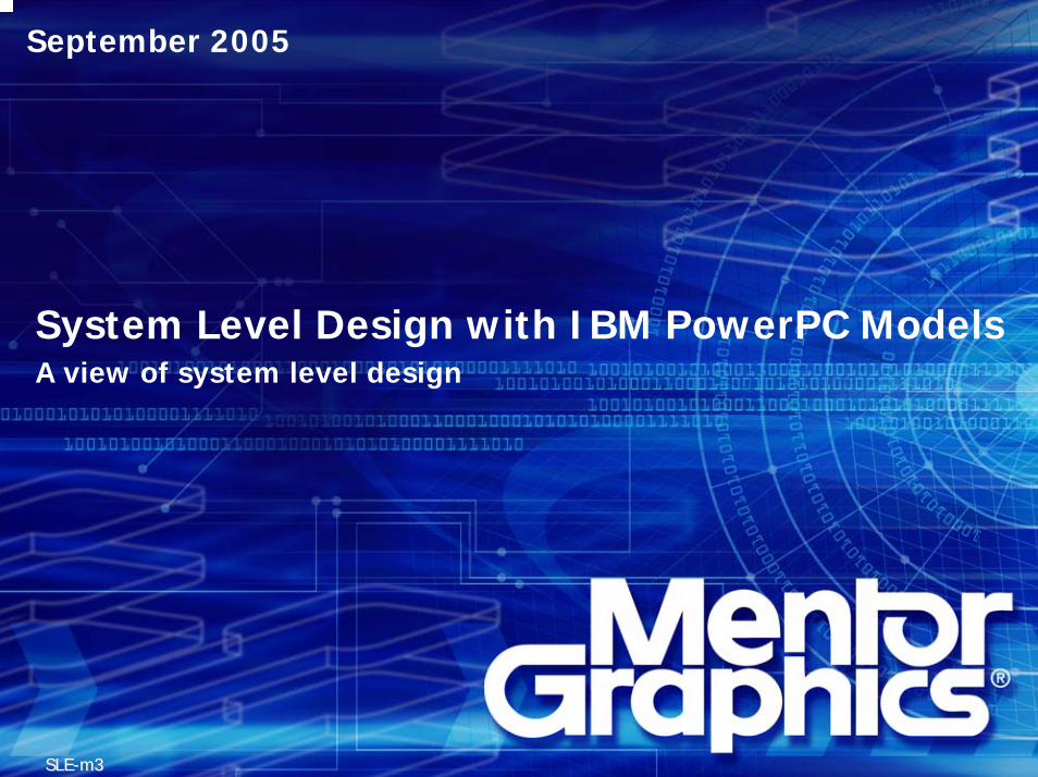
An Evolution of the “Traditional” FlowPaper SpecificationPaper SpecificationPaper Specification
High Level Model
Co-Verification HDL - RTL• Design• Debug• Verification
HDL HDL -- RTLRTL•• DesignDesign•• DebugDebug•• VerificationVerification
Application
BSP (drivers)
ApplicationApplication
BSP (drivers)BSP (drivers)
RTOSRTOS
Software HardwareSoftwareSoftware HardwareHardware
HardwareHigh Level Model
HardwareHardwareHigh Level ModelHigh Level Model
System High Level ModelExecutable Specification
System High Level ModelSystem High Level ModelExecutable SpecificationExecutable Specification
Consistent Verification
Requirements follow-up
SoftwareSoftwareSoftwareVirtual Prototype

SLE Division, A view of system level design, September 20056
Register Transfer LevelRegister Transfer Level
Hardware Transaction LevelHardware virtual prototyping, high level verification environment,
architecture refinement, performance verification
Hardware Transaction LevelHardware virtual prototyping, high level verification environment,
architecture refinement, performance verification
System Exploration LevelSystem executable specification, architecture exploration,
HW/SW partitioning, mapping of functional list on HW/SW resources
System Exploration LevelSystem executable specification, architecture exploration,
HW/SW partitioning, mapping of functional list on HW/SW resources
Algorithmic LevelFunctional design and verification,
exploration of the functional requirement list
Algorithmic LevelFunctional design and verification,
exploration of the functional requirement listExplore the feasibility of requirementsExplore the feasibility of requirements
Partition HW and SW - Define the architectureFinalize the specification
Partition HW and SW - Define the architectureFinalize the specification
Create a first prototype of the HWCreate a verification infrastructureCreate a first prototype of the HWCreate a verification infrastructure
Implement the hardware at register levelImplement the hardware at register level
System Level Tasks and Stages
SystemLevel
Design
Functional RequirementsFunctional Requirements
GatesGates
Uncommitted Systems
HardwareCommitted

SLE Division, A view of system level design, September 20057
Advantages of System Level Design
Functional behavior validated early in the process speeds the flow to working silicon
Fast execution allows architectural exploration to find the best design alternatives and encourages more testing to eliminate functional bugs
The system level model serves as a rapid, updateable early prototype to support concurrent software development

SLE Division, A view of system level design, September 20058
Hardware FlowHardware Flow
Software FlowSoftware Flow
A view of system level design
GoldenVerification Model
GoldenVerification Model
Power MetricsPower Metrics
PerformanceMetrics
PerformanceMetrics
Virtual Prototypefor SW
Virtual Prototypefor SWTLM ModelsTLM Models
RTLRTL
Manual DesignManual DesignManual Design
Manual Design /Interface Automation
Manual Design /Manual Design /Interface AutomationInterface Automation
AlgorithmicC Synthesis
AlgorithmicAlgorithmicC SynthesisC Synthesis
SystemAssembly
RTL
SystemSystemAssemblyAssembly
RTL
SimulationEnvironment
RTL
SimulationSimulationEnvironmentEnvironment
RTLVerified
Implementation
VerifiedImplementation
UMLUML
IP LibraryIP LibraryIP Library
xtUMLExecuter &Compiler
xtUMLxtUMLExecuter &Executer &CompilerCompiler
C CodeC Code C Compiler/ linker
C CompilerC Compiler/ linker/ linker Host / Target CodeHost / Target Code
C AlgorithmC Algorithm
TLMTLM
RTOSRTOSRTOS
RTOSRTOS
Compilers/DebuggersCompilers/Debuggers
ApplicationsApplications
MiddlewareMiddleware
ArchitectureArchitecture
Logic DesignLogic Design
VerificationVerification
Physical DesignPhysical Design

SLE Division, A view of system level design, September 20059
Merged MGC Merged MGC -- IBM SLD PowerPC PlatformIBM SLD PowerPC Platform
TOSTOSTOS
H2CH2CH2C
HDLHDL
HDL & CHDL & C--Based DesignBased Design
Catapult CCatapult CCatapult CHDL DesignerHDL DesignerHDL Designer
DesignAnalystDesignAnalystDesignAnalyst
((Co)SimulationCo)Simulation
Platform ExpressPlatform ExpressPlatform Express
Seamless | PerspectaSeamless | Seamless | PerspectaPerspecta
Model ExpressModel ExpressModel Express
BEAMBEAMBEAM
Embedded SystemsEmbedded Systems
xtUMLxtUML
C/CC/C++++/SystemC/SystemC
Nucleus BridgePointNucleus Nucleus BridgePointBridgePoint
SoC VirtualDesign Creation
SoCSoC VirtualVirtualDesign CreationDesign Creation
FloorplanningFloorplanningFloorplanning Power AnalysisPower AnalysisPower Analysis
IBM IBM ChipBenchChipBench SOC Virtual Design CreationSOC Virtual Design Creation
Voltage IslandsVoltage IslandsVoltage Islands ImplementationImplementationImplementation
ModelsimModelsimModelsim
Digital SimulationDigital Simulation
C•D•VCC••DD••VV A•V•MAA••VV••MMA•B•VAA••BB••VV Testbenches:SystemC/SystemVerilog/C/C++/PSL
Verilog/VHDL
TestbenchesTestbenches::SystemC/SystemC/SystemVerilogSystemVerilog/C/C++/PSL/C/C++/PSL
VerilogVerilog/VHDL/VHDL
IBMIBMIBM
MGCMGCMGC

SLE Division, A view of system level design, September 200510
Modeling Abstraction / Languages
C/C++
RTL
UML
System Verilog
SystemC
Behavioral Specification
Architectural Exploration
Transaction-level Verification
Cycle Accurate Verification
RTL Verification
SLE Division, A view of system level design, September 200511
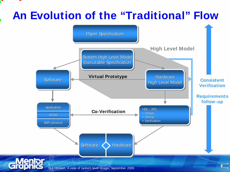
xtUML for Initial System Modeling
TLM ModelsTLM Models
UMLUML
Future?Future?
Build &CompileBuild &Build &CompileCompile C CodeC Code
C AlgorithmC Algorithm
ModelDebugModelModelDebugDebug
Generate 100% C/C++ Code from the model
Model Verifier
Graphical UML Entry
Use functional requirements specification as inputBuild platform-independent executable models of
the Application & Test Suite
Reference external models such as C/C++ algorithms
suitable for Catapult C
Future: xtUML to TLM Compiler could build Software + Hardware platform for performance
analysis & architecture validation

SLE Division, A view of system level design, September 200512
Algorithmic C Synthesis
TLM ModelsTLM Models
RTLRTL
AlgorithmicC Synthesis
AlgorithmicAlgorithmicC SynthesisC SynthesisC AlgorithmC Algorithm
Use ANSI C++ : Focus on the Functional IntentExplore the design space to find the optimum
micro-architecture
Generate TLM models (un-timed,
timed & CA)
Synthesize RTL & Generate testbench
infrastructure
TLM
SimulationEnvironment
RTL
TLM
SimulationSimulationEnvironmentEnvironment
RTL
Links to Simulation
Environments
Constraints
Use TLM Performance Analysis to Refine Block Constraints

SLE Division, A view of system level design, September 200513
Transaction Level Modeling & Simulation
Power MetricsPower Metrics
PerformanceMetrics
PerformanceMetrics
Virtual Prototypefor SW
Virtual Prototypefor SWTLM ModelsTLM Models
Manual Design /Interface Automation
Manual Design /Manual Design /Interface AutomationInterface Automation
TLM
SystemAssembly
TLM
SystemSystemAssemblyAssembly
TLM
SimulationEnvironment
TLM
SimulationSimulationEnvironmentEnvironment
IP LibraryIP LibraryIP Library
Host/Target CodeHost/Target Code
Assemble Structural System Design from existing IP and new user-created models
Validate and analyze system function and performance
Use Interface Generation Tools to simplify new TLM creation
Generate additional TLMs from
xtUML or C++ algorithms
OSCI TLM and SPIRIT standards increase IP library availability
Simulation Environment common between TLM and RTL
TLM simulation speed 100k -> 2M IPS
Processor cores for software execution
SLE Division, A view of system level design, September 200514
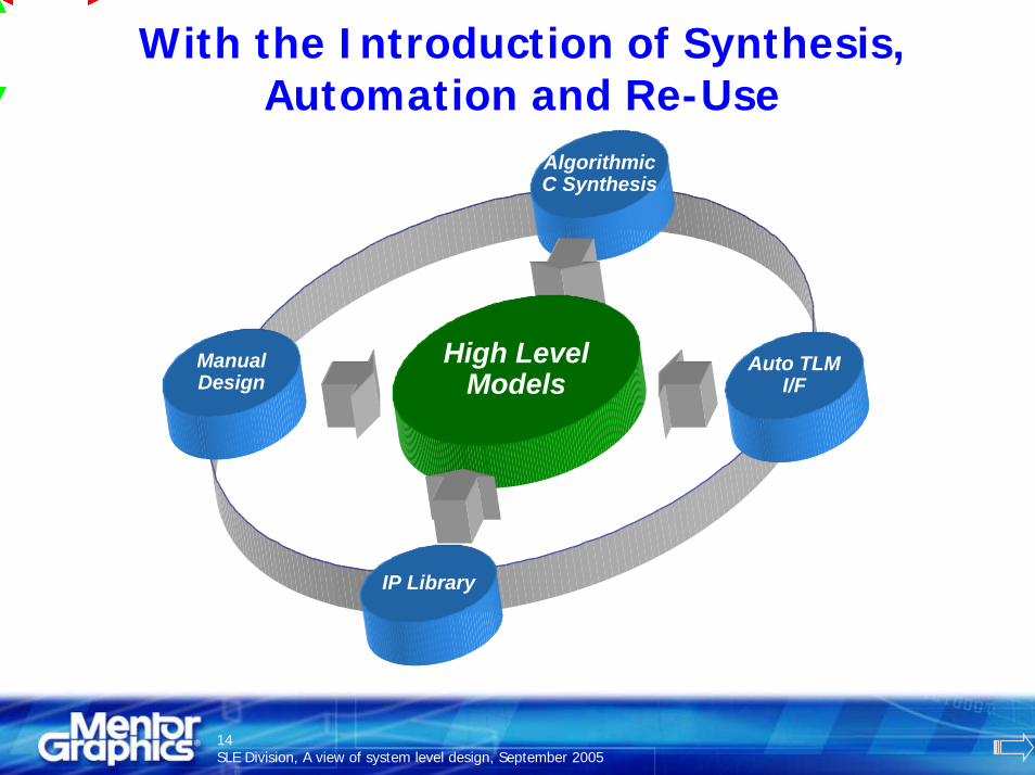
With the Introduction of Synthesis, Automation and Re-Use
AlgorithmicC Synthesis
High LevelModels
ManualDesign
Auto TLMI/F
IP Library

SLE Division, A view of system level design, September 200515
…The Value of High Level Modeling is Made Accessible
Architects
High LevelModels
SoftwareTeam
VerificationTeam
DesignTeam

SLE Division, A view of system level design, September 200516
To Provide a Complete System-level Design Process
Capture designas executablespecification
Validatefunctionality
Capture designCapture designas executableas executablespecificationspecification
ValidateValidatefunctionalityfunctionality
Behavioral / Functional Modeling
RTLVerification
RTLRTLVerificationVerification
Compile& Link
CompileCompile& Link& Link
ApplicationTesting
ApplicationApplicationTestingTesting
Application S/W Validation
Refine blocktiming &power
SynthesizeRTL
Refine blockRefine blocktiming &timing &powerpower
SynthesizeSynthesizeRTLRTL
Micro-Architecture Implementation
Structuredesign
Validatearchitecture
Analyzeperformance
StructureStructuredesigndesign
ValidateValidatearchitecturearchitecture
AnalyzeAnalyzeperformanceperformance
Architectural Design
GenerateS/W Code(& TLMs)
GenerateGenerateS/W CodeS/W Code(& (& TLMsTLMs))
Performance analysis includes timing & power
Both s/w and h/w dependent effects
S/W <-> H/W integration testing is done at TLM &
RTL
SLE Division, A view of system level design, September 200517
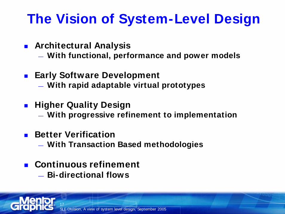
The Vision of System-Level Design
Architectural Analysis— With functional, performance and power models
Early Software Development— With rapid adaptable virtual prototypes
Higher Quality Design— With progressive refinement to implementation
Better Verification— With Transaction Based methodologies
Continuous refinement— Bi-directional flows

SLE Division, A view of system level design, September 200518
Key Productivity Directions
Model system or function at the highest appropriate level
— xtUML for system behavior— TLMs for architecture— C++ for algorithms
Automation & Re-Use— xtUML to embedded C code— C++ algorithm to SystemC TLM— Automated SystemC TLM interface generation— xtUML to TLM— TLM Model Interoperability
Catapult C, Perspecta, Questa, virtual prototypes— C++ algorithm to RTL— Embedded PowerPC aware platform

A View of System Level DesignTechnologies & MethodologiesConclusion

SLE Division, A view of system level design, September 200520
Transaction Level Modeling
AA
MemMem
Generic CPUGeneric CPU(B, C and ctrl)(B, C and ctrl)
DD
TLM Channel
AA
MemMem
Specific CPU Specific CPU -- ISSISS(B, C and ctrl)(B, C and ctrl)
DD
Bus
Transactions
TLM API
TLM APITLM API
TLM API
AA CC DD
BB
TLMTLM RTLRTLAlgorithmicAlgorithmic
This is a methodology, also known as TLM, that defines new abstraction levels above the register.
It is itself made of several stages, which gradually abstract from hardware implementation constraints but still with a structured view of the design.
Its goal is to reduce the number of events and the amount of data that has to be treated during simulation.
This modeling method is built as a set of interfaces that define how models communicates.
HardwareASIC/FPGA
Place & Route
RTLSynthesis
Fixed PointC++ Model
Floating PointModel
Catapult CSynthesisConstraints +
LogicAnalyzer
Algorithm Functional Description
Floating PointModel
Fixed PointModel
Micro-architectureDefinition
RTLDesign
RTL Area/TimingOptimization
RTLSynthesis
Place & Route
HardwareASIC/FPGA
ManualMethods
Logic Analyzer
+
MATLABSPW
C/C++
Precision RTLor DC
ASIC or FPGAVendor
Algorithm Functional Description
Syst
em D
esig
ner
Har
dwar
e D
esig
ner
Vend
or
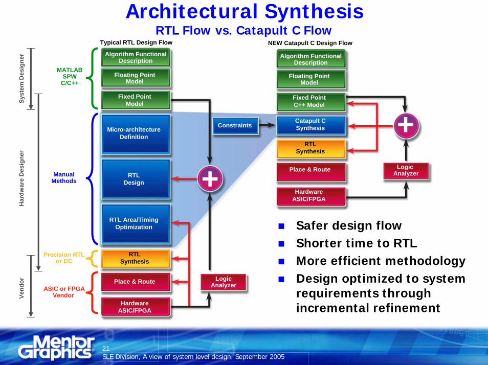
Typical RTL Design Flow NEW Catapult C Design Flow
Safer design flowShorter time to RTLMore efficient methodologyDesign optimized to system requirements through incremental refinement
Architectural SynthesisRTL Flow vs. Catapult C Flow
SLE Division, A view of system level design, September 200521
SLE Division, A view of system level design, September 200522
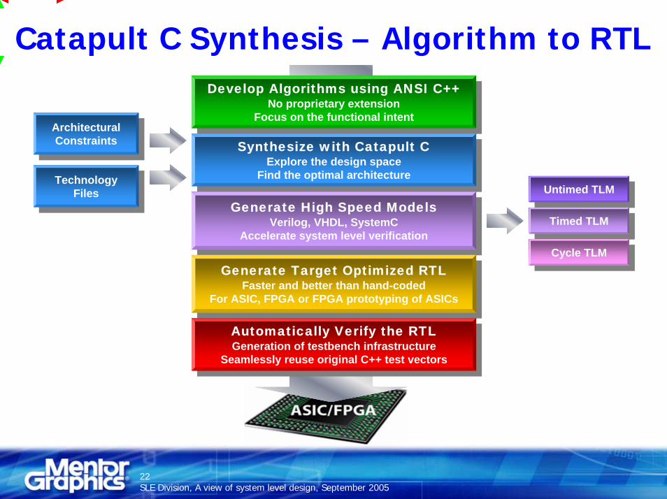
Catapult C Synthesis – Algorithm to RTLDevelop Algorithms using ANSI C++
No proprietary extensionFocus on the functional intent
Develop Algorithms using ANSI C++No proprietary extension
Focus on the functional intent
Synthesize with Catapult CExplore the design space
Find the optimal architecture
Synthesize with Catapult CExplore the design space
Find the optimal architectureTechnology
FilesTechnology
Files
ArchitecturalConstraints
ArchitecturalConstraints
Generate High Speed ModelsVerilog, VHDL, SystemC
Accelerate system level verification
Generate High Speed ModelsVerilog, VHDL, SystemC
Accelerate system level verification
Untimed TLMUntimed TLM
Timed TLMTimed TLM
Cycle TLMCycle TLM
Generate Target Optimized RTL Faster and better than hand-coded
For ASIC, FPGA or FPGA prototyping of ASICs
Generate Target Optimized RTL Faster and better than hand-coded
For ASIC, FPGA or FPGA prototyping of ASICs
Automatically Verify the RTLGeneration of testbench infrastructure
Seamlessly reuse original C++ test vectors
Automatically Verify the RTLGeneration of testbench infrastructure
Seamlessly reuse original C++ test vectors
PerspectaPerspectaPerspecta
System Level Assembly
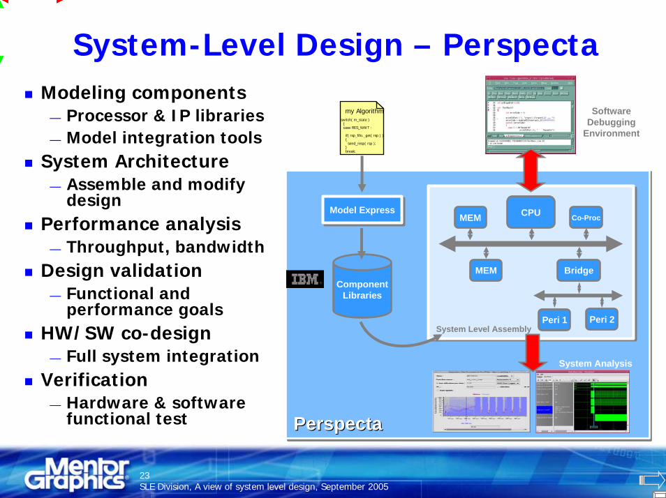
System-Level Design – PerspectaModeling components
— Processor & IP libraries— Model integration tools
System Architecture— Assemble and modify
designPerformance analysis
— Throughput, bandwidthDesign validation
— Functional and performance goals
HW/SW co-design— Full system integration
Verification— Hardware & software
functional test
System Level Assembly
MEM CPU Co-Proc
MEM Bridge
Peri 1 Peri 2
ComponentLibraries
Model ExpressModel Express
my Algorithmswitch( m_state )
{case RES_WAIT :
if( rsp_fifo._get( rsp ) ){send_resp( rsp );
}break;
Software Debugging
Environment
System Analysis
SLE Division, A view of system level design, September 200523

SLE Division, A view of system level design, September 200524
Power Analysis in PerspectaProvides a mechanism to dynamically record and display power consumption across the whole systemSuitable for comparison of different architectural options
— Includes software dependent effectsAccuracy is driven by power characterization data available to the modeler
— Can be ‘data book’ level or better— Only limited by level of the TLM in question

SLE Division, A view of system level design, September 200525
Component Power Modeling
Within the functional model— Associate known power profile
with each distinct model stateUse an API to set the new mode dependent state
— Allocate energy value for particular events
Also records the duration
Modeling power requires— Addition of handful of API calls
inside existing model— High-level power
characterization of the blocks being modeled
IDLE mode 20uW
Processing Mode 500uW
Data Transmit Mode 300uW
I/O64b
32nJ
400ns
64b * (0.5nJ/b write energy) = 32nJ
16 word burst = 5clks(init) + 15x1clks(beat) = 2020clks * 20ns period = 400ns
SLE Division, A view of system level design, September 200526
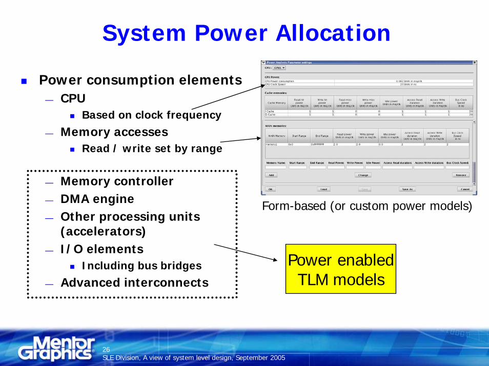
System Power Allocation
Power consumption elements— CPU
Based on clock frequency
— Memory accessesRead / write set by range
— Memory controller— DMA engine— Other processing units
(accelerators)— I/O elements
Including bus bridges— Advanced interconnects
Power enabledTLM models
Form-based (or custom power models)
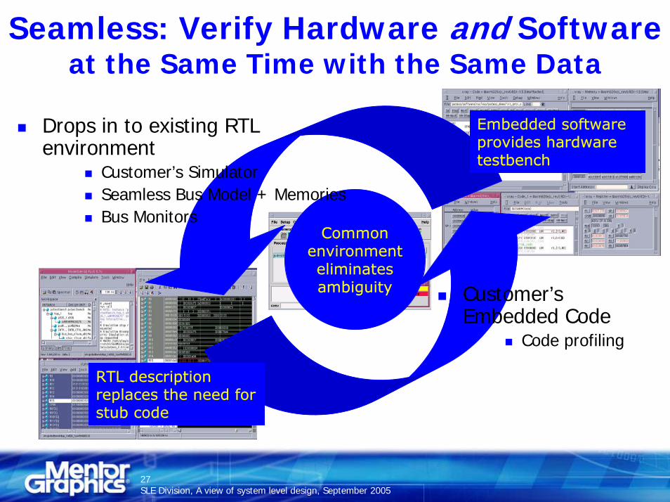
Seamless: Verify Hardware and Softwareat the Same Time with the Same Data
Embedded softwareprovides hardware testbench
RTL description replaces the need forstub code
Commonenvironmenteliminatesambiguity
Drops in to existing RTL environment
Customer’s SimulatorSeamless Bus Model + MemoriesBus Monitors
Customer’s Embedded Code
Code profiling
SLE Division, A view of system level design, September 200527
SLE Division, A view of system level design, September 200528
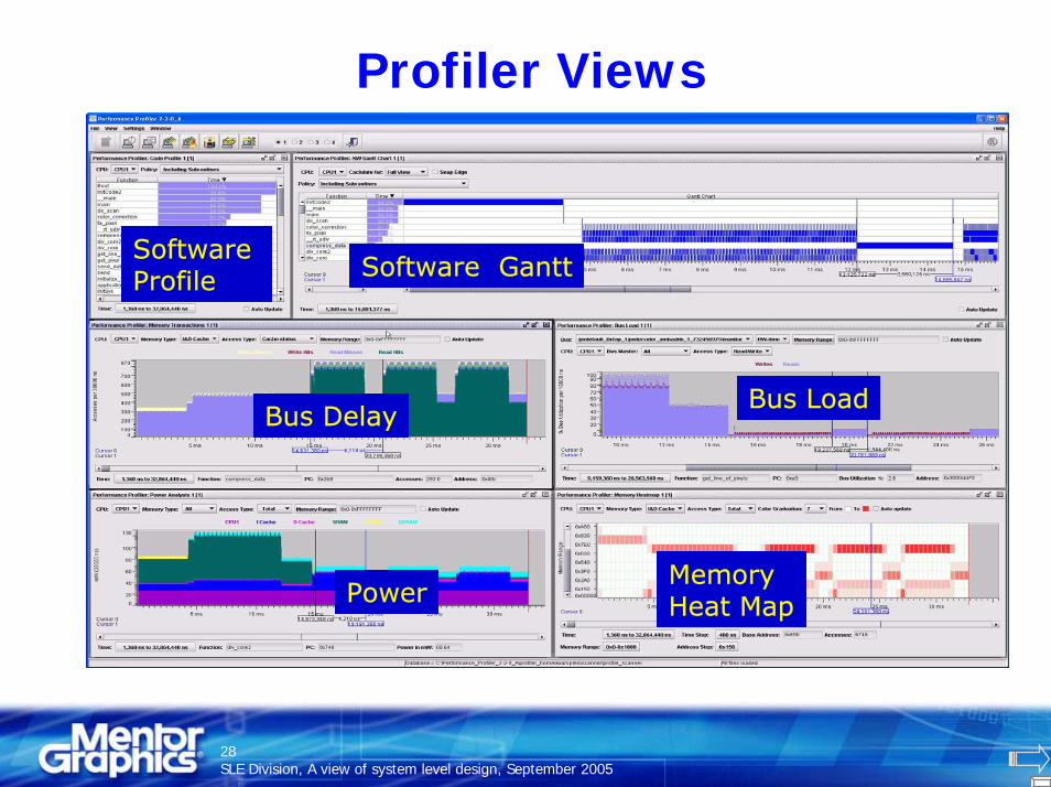
Profiler Views
Software Profile
Bus Load
Software Gantt
Bus Delay
PowerMemoryHeat Map

SLE Division, A view of system level design, September 200529
Progressive Refinement to RTLAssemble Transaction Level Models
performance & power
Simulate to validate functionality,
Substitute IP models
Synthesize algorithms
Add specific RTL blocks
Create new elements
Floorplan, Power Islands & Implement
ComponentLibrary
Seamless

BridgePointBridgePoint
System-Level Software – BridgePointExecutable, Translatable UML (xtUML)
Application Models in xtUML:— Platform-independent— Executable— Capture subject-matter expertise— Enable large-scale reuse— Integrate with legacy code
Early verification before:— HW/SW partitioning— Processor selection— Target language selection— RTOS selection— Target model compiler is available
Model Compilers for xtUML:— Application-independent— Provide complete code generation— Generate optimized code— Delivered in source for customization— Verify independent of application
models
ModelConstruction
Model Execution and Verification
Model Compilation
my Codeswitch( m_state )
{case RES_WAIT :
if( rsp_fifo._get( rsp ) ){send_resp( rsp );
}break;
Model Debugging
Cause and Effect
SLE Division, A view of system level design, September 200530
SLE Division, A view of system level design, September 200531
BridgePoint Flow for System Specification
Use functional requirements specification as inputBuild platform-independent executable models of:
— Application— Test Suite
Verify application behavior on host:— Application models— C Algorithms— Legacy SW, commercial middleware, RTOS
Buy or build model compiler for targetMark models as hardware and software

SLE Division, A view of system level design, September 200532
System-Level Engineering
RTL
ESL
Embe
dded
So
ftwar
e
Adv
ance
Va
lidat
ion
Synt
hesi
s
Sim
ulat
ion
With a unique breadth of expertise in the key domains that make up System Level Design and ESL today, Mentor Graphics is well positioned to lead in it’s evolution.
A strong partnership between design automation solutions, system IP suppliers and design teams defines the direction of next generation systems.

SLE Division, A view of system level design, September 200533