Embed Size (px)
Citation preview
Synthetic Control of Organic Semiconductor Excited States
by
Tabitha Ann Clem
A dissertation submitted in partial satisfaction of the
requirements for the degree of
Doctor of Philosophy
in
Chemistry
in the
Graduate Division
of the
University of California, Berkeley
Committee in charge:
Professor Jean M. J. Fréchet, Chair Professor Kenneth N. Raymond Professor Rachel A. Segalman
Spring 2010

Synthetic Control of Organic Semiconductor Excited States
© 2010
by Tabitha Ann Clem

Abstract
Synthetic Control of Organic Semiconductor Excited States
by
Tabitha Ann Clem
Doctor of Philosophy in Chemistry
University of California, Berkeley
Professor Jean M. J. Fréchet, Chair
This work describes the synthesis, and study of new organic and organometallic compounds designed to possess modified excited states for applications in electronic devices, with a particular focus on photovoltaics. The first chapter introduces the origin of semiconducting behavior in conjugated polymers, and how the properties of these semiconductors ultimately impact the fundamental physical processes occurring in organic electronic devices. The second chapter describes the synthesis, optoelectronic properties, and photovoltaic performance of a small molecule oligothiophene analog that possesses a considerable redshift in absorption relative to an unmodified oligothiophene. This redshift in absorption is the result of using a fused thiophene unit that acts as a driving force to enable dearomatization of the oligothiophene unit. The third chapter describes the preparation of wide band gap, phosphorescent cyclometalated platinum polymers and their application to bilayer photovoltaic devices where an increase in photocurrent is observed, and is attributed to an increase in the exciton diffusion length arising from formation of triplet excitons. The fourth chapter presents further development of cyclometalated platinum polymers, with a focus on tuning the photophysical properties and studying these materials in bulk heterojunction photovoltaic devices. The fifth chapter presents a study of cyclometalated platinum and iridium small molecules, describing their photophysical properties and solid-state structure, and exploring the application of these complexes to light emitting diodes. The final chapter describes the development of polythiophenes containing highly polarizable functional groups, with particular attention to the effect of these modifications on the optoelectronic properties and the dielectric constants of the resulting polymers. Together, these chapters present a study encompassing the modification of excited states in organic semiconductors, beginning with light absorption, continuing to modification of the spin state of the exciton, and ultimately modifying the dielectric constant of the active layer materials to affect charge separation and transport. Utilizing materials developed based on these principles provides an attractive new route to altering and enhancing the basic steps involved in the operation of organic electronic devices, ultimately producing both an improved understanding of the mechanism of device operation, and improved device performance.
1

Dedicated to Jean C. White
i
Table of Contents
Acknowledgements iiiChapter 1: Organic Electronics 1Chapter 2: Thieno[3,4-b]thiophene – Based Small Molecules for Organic Photovoltaics
16
Chapter 3: Cyclometalated Platinum Polymers for Bilayer Photovoltaics 25Chapter 4: Cyclometalated Platinum Polymers for Bulk Heterojunction Devices: Synthesis, Photophysical Properties and Photovoltaic Performance
36
Chapter 5: Cyclometalated Platinum and Iridium Complexes Containing a Thiazole Ligand: Experimental and Theoretical Investigations, and Application to Electronic Devices
59
Chapter 6: High Dielectric Constant Polythiophenes 83
ii

iii
Acknowledgements
First, I would like to thank Prof. Fréchet for serving as my advisor throughout my Ph.D. I am also grateful to Prof. Fréchet for bringing a former colleague, Dr. Justin Mynar, back into the group as a research professor and laboratory manager. Dr. Mynar’s efforts have facilitated the development of a positive, supportive, and organized working environment, for which I am very thankful. I also owe a great deal of thanks to a number of other colleagues, both within the Fréchet group and without. Barry Thompson was a fantastic person to learn from, both in terms of how to do chemistry and in terms of designing projects. David Kavulak has been a great person to work with & talk with about organic electronics. Claire Woo has been a dedicated, hardworking, and fantastic colleague. A number of other labmates have enriched my time in the Fréchet group, although we did not work together directly. I especially appreciate Jill Millstone’s guidance and support throughout my last two years here. She has truly been a role model in terms of being a productive scientist, an effective communicator, and an ethical, assertive colleague. I thoroughly enjoyed working alongside Derek van der Poll; his sense of humor has improved my graduate experience immeasurably. I am particularly grateful for the time I have spent in 709 Latimer. Dan, Paul, Alexandra, and Søren have all been great labmates; my time in 709 exemplifies a positive working environment. I am also thankful for a number of people outside the Fréchet group for making a challenging path much easier to navigate. I will miss Janel and Laura, and our brunches. I am particularly indebted to John Silliman, who has been a constant, unfailing source of support (and chocolate!) throughout this time. All of my friends and family back in Maryland have been an invaluable source of support. I am especially grateful to my undergraduate advisor, Andy Koch. Without his tireless enthusiasm and belief in my abilities, I would not be at Berkeley. The entire chemistry department at St. Mary’s College was instrumental in starting me on the path to becoming a researcher. Knowing that they are there, confident in my ability to succeed, has made graduate school much easier. Finally, I must thank my family. My grandmother has been a role model to me as a woman pursuing an education in a male-dominated field, and has also been a role model in terms of her kindness and efforts to help others. My mother and my sister have been eternally supportive of me pursuing my dreams, however lofty they may be. Last but not least, I am thankful for the wonderful furry friends in my life - especially Dutch, Fortune, and Scout, our family’s Pugs, and Rosie and Marie, my guinea pigs.

Chapter 1: Organic Electronics Organic Semiconductors Initial research into π-conjugated polymers began with the discovery of metallic character in doped polyacetylene, leading to an eventual Nobel Prize in chemistry for Alan Heeger, Alan McDairmid, and Hideki Shirakawa.1 Although initial work focused on the metallic properties of these materials in their “doped”, or partially oxidized state, in more recent history research in π-conjugated molecules has focused on developing the semiconducting properties of these materials in their neutral form. Organic semiconductors are particularly desirable as a low-cost replacement for traditional inorganic semiconductors in electronic devices2-6. While the intrinsic cost of certain inorganics are expected to remain high and even increase based on a low natural abundance, optimization of processing conditions can potentially drive the expense of organic semiconductors increasingly lower. Further, organic semiconductors can be made soluble in organic or aqueous systems, enabling them to be processed inexpensively using inkjet printing78 or roll-to-roll fabrication9, 10. The potential for low cost, straightforward device fabrication, combined with the highly tunable properties of organic semiconductors, make these materials worthy of significant investigation into their material and chemical properties. Successful tuning of the properties of π-conjugated materials for electronic devices relies on an understanding of both the operating mechanism of the targeted device, and an understanding of the structure-property relationships in π-conjugated materials. The following chapter addresses the origin and modification of semiconducting behavior in π-conjugated materials, as well as the fundamental processes occurring in organic photovoltaic (OPV) devices. π-Conjugated Materials as Semiconductors The origin of semiconducting behavior in π-conjugated materials can best be understood by considering the molecular energy levels of oligo(acetylene)s of increasing length. Figure 1 shows a schematic of energy levels in 1,3-butadiene, as well as the effect of adding additional conjugated units to the molecule. As the conjugation length of the small molecule is increased, there are increasing numbers of orbitals beneath the HOMO and above the LUMO. Additionally, the energy difference between the HOMO and the LUMO decreases. When this is extrapolated to a polymer such as polyacetylene, there are sufficient occupied and unoccupied orbitals to resemble the valence and conducting band of an inorganic semiconductor. Further, the energy difference between the HOMO and the LUMO is sufficiently small for the material to be considered a semiconductor. While polyacetylene is seldom used for electronic applications, this concept can be applied to other materials based on arene derivatives.
1

Figure 1. Energy Diagram of Acetylene-Based Materials Aromatic systems such as benzene11, thiophene12-14, pyrrole15, and others have seen extensive use in organic semiconductors. Visible light absorption and semiconducting behavior arises and varies with changing the length of the molecule as well as the structure of the conjugated units. OPV Device Operation Successfully designing materials to modify and enhance the fundamental physical processes occurring in an OPV requires first an understanding of the mechanism of device operation. The mechanism of photocurrent production in an OPV is shown schematically in Figure 2. Photocurrent begins with absorption of light in either a donor (p-type) or acceptor (n-type) material to form an exciton (1). In organic semiconductors, tightly-bound electron-hole pairs (excitons) are formed. This exciton migrates randomly through a material until it reaches an interface between donor and acceptor materials (2). Once at the interface, the exciton will be split across the donor and the acceptor to form a geminate pair16 (3). This Coulombically bound species then splits into free charge carriers, which migrate to their respective electrodes under the influence of the built-in electric field from the two electrodes (4).
Figure 2. OPV Device Operation
2
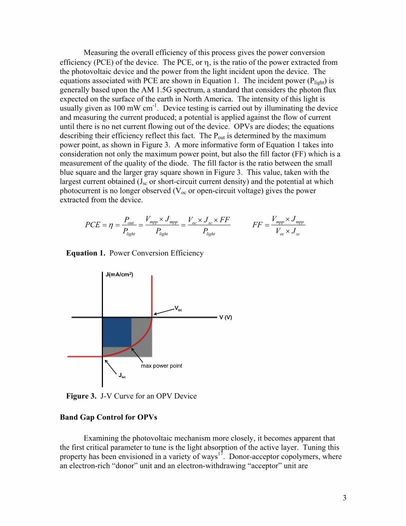
Measuring the overall efficiency of this process gives the power conversion efficiency (PCE) of the device. The PCE, or η, is the ratio of the power extracted from the photovoltaic device and the power from the light incident upon the device. The equations associated with PCE are shown in Equation 1. The incident power (Plight) is generally based upon the AM 1.5G spectrum, a standard that considers the photon flux expected on the surface of the earth in North America. The intensity of this light is usually given as 100 mW cm-1. Device testing is carried out by illuminating the device and measuring the current produced; a potential is applied against the flow of current until there is no net current flowing out of the device. OPVs are diodes; the equations describing their efficiency reflect this fact. The Pout is determined by the maximum power point, as shown in Figure 3. A more informative form of Equation 1 takes into consideration not only the maximum power point, but also the fill factor (FF) which is a measurement of the quality of the diode. The fill factor is the ratio between the small blue square and the larger gray square shown in Figure 3. This value, taken with the largest current obtained (Jsc or short-circuit current density) and the potential at which photocurrent is no longer observed (Voc or open-circuit voltage) gives the power extracted from the device.
light
scoc
light
mppmpp
light
out
PFFJV
PJV
PPPCE ××
=×
=== η scoc
mppmpp
JVJV
FF××
=
Equation 1. Power Conversion Efficiency
Figure 3. J-V Curve for an OPV Device
Band Gap Control for OPVs
Examining the photovoltaic mechanism more closely, it becomes apparent that the first critical parameter to tune is the light absorption of the active layer. Tuning this property has been envisioned in a variety of ways17. Donor-acceptor copolymers, where an electron-rich “donor” unit and an electron-withdrawing “acceptor” unit are
3

copolymerized to yield a conjugated polymer, are attractive materials for organic electronics for a variety of reasons. The synthetic ease of developing orthogonally functionalized coupling partners makes it possible to develop and study a wide range of structures that are varied in a controlled manner. Further, donor-acceptor copolymers exhibit optical band gaps and electronic properties that can be tuned by varying either or both the donor and acceptor unit, giving access to a broad range of materials properties. This is particularly critical given the limited overlap with the solar spectrum seen for high-performing homopolymers used in photovoltaics. While π-conjugated homopolymers exhibit a lower band gap relative to their small molecule counterparts primarily as the result of extended delocalization along the polymer backbone, the mechanism by which lower band gaps are achieved in donor-acceptor polymers is primarily based on preferential localization of the HOMO of the polymer to the donor unit, and the LUMO of the polymer to the acceptor unit. This is shown schematically in Figure 4. It is important to note that the poor orbital overlap between the HOMO and the LUMO can result in lowered absorption coefficients18, 19, on the order of 10-4 cm-1, though not all donor-acceptor copolymers exhibit this problem20. The extent to which lowered absorption coefficients are detrimental to device performance is unclear because only normalized absorption spectra are reported for most materials.
Figure 4. Orbital Mixing to Decrease Band Gap in Donor-Acceptor Polymers A wide variety of donor and acceptor units have been used in the literature. Commonly used acceptor units studied include thienopyrazine18, 21-24, quinoxaline21,25-28, and benzothiadiazole, the structures of which are shown in Figure 5. The acceptor unit that has shown the most promise in high-performing systems is benzothiadiazole. The origin of the exceptional performance of benzothiadiazole copolymers may be based on a number of factors. First, a pendant five-membered ring is expected to show decreased steric interactions with adjacent aromatic units on the polymer chain relative to a pendant six-membered ring. Units such as quinoxaline and thienopyrazine are therefore expected to have increased steric interactions with adjacent repeat units as compared to
4

benzothiadiazole. The decreased steric interactions anticipated for benzothiadiazole may lower the band gap and favor delocalization along the polymer backbone by favoring a coplanar orientation of adjacent repeat units. The strong dipole moment of donor-acceptor copolymers is believed to facilitate charge separation. The dipole moment of benzothiadiazole29 (1.79 D) is more than three times that of another common acceptor quinoxaline30 (0.55 D), and this considerably larger dipole moment for benzothiadiazole can lead to a more polarized excited state, promoting charge separation.
Figure 5. Chemical structures of (a) quinoxaline, (b) benzothiadiazole and (c) thienopyrazine Several polymers utilizing a benzothiadiazole acceptor have achieved efficiencies greater than five percent, as have copolymers of dithienylbenzothiadiazole. The optoelectronic properties and photovoltaic performance of several donor-acceptor copolymers using a fused biphenyl derivative as part of the donor unit and a benzothiadiazole acceptor are summarized in Table 1. Fused biphenyl derivatives are attractive building blocks in these copolymers for a number of reasons. Covalently linking the adjacent phenyl rings forces them into a coplanar confirmation, which is favorable for delocalization along the polymer backbone. Moreover, the nature of the connecting atom can potentially have profound effects on the properties of the resulting polymer, since both the electronegativity and the geometry of the connecting atom can modify the electronic properties and the π−π stacking of the polymer. In comparing the optoelectronic and photovoltaic properties of the fused biphenyl-based donor-acceptor copolymers, a number of trends begin to emerge. All of these polymers posses a camelback absorption, with one absorption peak at shorter wavelengths and one at longer wavelengths. With the exception of P1, the best photovoltaic devices are obtained with these materials in blend films less than 100 nm thick. More detailed studies of P1 have shown that internal quantum efficiency (IQE) is close to 66% for films up to 140 nm thick; thicker films show a decrease in IQE. Table 1. Properties of donor-acceptor copolymers using fused biphenyl repeat units
Polymer P131,32 P220,33-35 P336 X C(C10H21)2 NCH(C8H17)2 Si(C8H17)2 Eg (eV) 1.9 1.88 1.85 HOMO (eV) -5.4 -5.49 -5.73 LUMO (eV) -3.5 -3.64 -3.88 Polymer:Fullerene 1:4a 1:2a, c /1:2b 1:2b,c
5
Ratio η (%) 4.2a 4.35a/6.1b 5.4b,c
Jsc (mA cm-2) 7.7 9.42a/10.6b 9.5
Voc (V) 0.999 0.9a/0.88b 0.97
FF 54 51a/66b 55
Thickness (nm) 186 60a/70b 70
awith PC60BM bwith PC70BM cat 80 mW cm-2
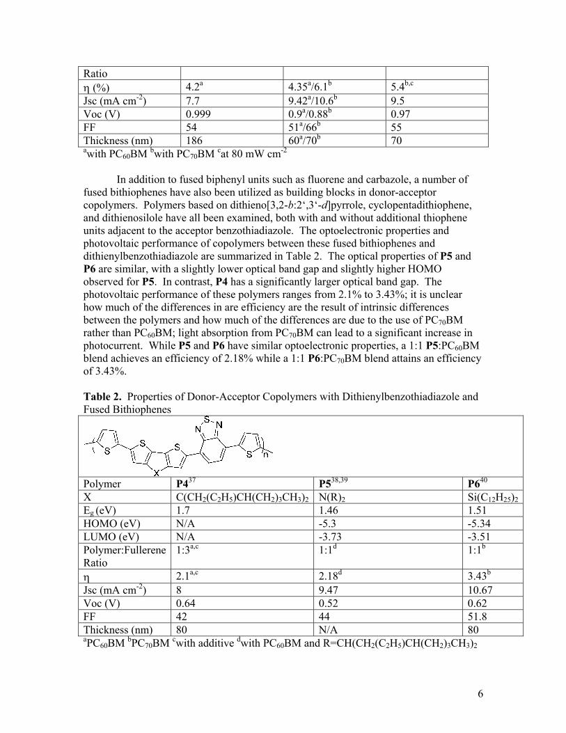
In addition to fused biphenyl units such as fluorene and carbazole, a number of fused bithiophenes have also been utilized as building blocks in donor-acceptor copolymers. Polymers based on dithieno[3,2-b:2‘,3‘-d]pyrrole, cyclopentadithiophene, and dithienosilole have all been examined, both with and without additional thiophene units adjacent to the acceptor benzothiadiazole. The optoelectronic properties and photovoltaic performance of copolymers between these fused bithiophenes and dithienylbenzothiadiazole are summarized in Table 2. The optical properties of P5 and P6 are similar, with a slightly lower optical band gap and slightly higher HOMO observed for P5. In contrast, P4 has a significantly larger optical band gap. The photovoltaic performance of these polymers ranges from 2.1% to 3.43%; it is unclear how much of the differences in are efficiency are the result of intrinsic differences between the polymers and how much of the differences are due to the use of PC70BM rather than PC60BM; light absorption from PC70BM can lead to a significant increase in photocurrent. While P5 and P6 have similar optoelectronic properties, a 1:1 P5:PC60BM blend achieves an efficiency of 2.18% while a 1:1 P6:PC70BM blend attains an efficiency of 3.43%. Table 2. Properties of Donor-Acceptor Copolymers with Dithienylbenzothiadiazole and Fused Bithiophenes
Polymer P437 P538,39 P640 X C(CH2(C2H5)CH(CH2)3CH3)2 N(R)2 Si(C12H25)2Eg (eV) 1.7 1.46 1.51 HOMO (eV) N/A -5.3 -5.34 LUMO (eV) N/A -3.73 -3.51 Polymer:Fullerene Ratio
1:3a,c 1:1d 1:1b
η 2.1a,c 2.18d 3.43b
Jsc (mA cm-2) 8 9.47 10.67Voc (V) 0.64 0.52 0.62FF 42 44 51.8Thickness (nm) 80 N/A 80 aPC60BM bPC70BM cwith additive dwith PC60BM and R=CH(CH2(C2H5)CH(CH2)3CH3)2
6
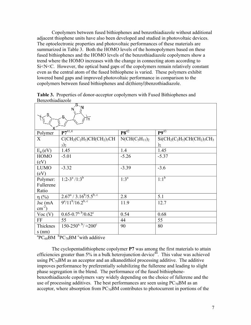
Copolymers between fused bithiophenes and benzothiadiazole without additional adjacent thiophene units have also been developed and studied in photovoltaic devices. The optoelectronic properties and photovoltaic performances of these materials are summarized in Table 3. Both the HOMO levels of the homopolymers based on these fused bithiophenes and the HOMO levels of the benzothiadiazole copolymers show a trend where the HOMO increases with the change in connecting atom according to Si<N<C. However, the optical band gaps of the copolymers remain relatively constant even as the central atom of the fused bithiophene is varied. These polymers exhibit lowered band gaps and improved photovoltaic performance in comparison to the copolymers between fused bithiophenes and di(thienyl)benzothiadiazole. Table 3. Properties of donor-acceptor copolymers with Fused Bithiophenes and Benzothiadiazole
Polymer P741,4 P842 P943 X C(CH2(C2H5)CH(CH2)3CH
3)2 N(CH(C5H11)2 Si(CH2(C2H5)CH(CH2)3CH3
)2 Eg (eV) 1.45 1.4 1.45 HOMO (eV)
-5.01 -5.26 -5.37
LUMO (eV)
-3.32 -3.39 -3.6
Polymer:Fullerene Ratio
1:2-3a /1:3b 1:3a 1:1b
η (%) 2.67a / 3.16b/5.5b, c 2.8 5.1Jsc (mA cm-2)
9a/11b/16.2b, c 11.9 12.7
Voc (V) 0.65-0.7a, b/0.62c 0.54 0.68 FF 55 44 55 Thickness (nm)
150-250a, b/ ≈200c 90 80
aPC60BM bPC70BM cwith additive The cyclopentadithiophene copolymer P7 was among the first materials to attain efficiencies greater than 5% in a bulk heterojunction device44. This value was achieved using PC70BM as an acceptor and an alkanedithiol processing additive. The additive improves performance by preferentially solubilizing the fullerene and leading to slight phase segregation in the blend. The performance of the fused bithiophene-benzothiadiazole copolymers vary widely depending on the choice of fullerene and the use of processing additives. The best performances are seen using PC70BM as an acceptor, where absorption from PC70BM contributes to photocurrent in portions of the
7

AM 1.5 spectrum where the polymer does not absorb light. The EQEs at long wavelengths in devices made from these polymers also vary from 0.3 to 0.4, where the highest values are achieved for P9, followed by P7 and finally P8. Although the photovoltaic performance of donor-acceptor copolymers varies widely with polymer structure, choice of acceptor, and use of processing additives, there are some general trends that can be observed. For all of the polymers discussed here with the exception of P7 and P1, the optimal device efficiencies are found for devices less than 100 nm thick. This is in stark contrast to P3HT:PC60BM devices, where the optimal device thicknesses are on the order of 200 nm. Moreover, the majority of high-performing donor-acceptor copolymers achieve their best efficiencies in the absence of annealing, suggesting there is minimal development of ordered domains in the blend. Together these data suggest that charge transport is less ordered in these systems as compared to the P3HT:PC60BM system, necessitating a thinner device for effective charge extraction. While benzothiadiazole has been used extensively as an acceptor unit, other chalcogens may be substituted for the central sulfur atom of this system. This change in the chemical structure is expected to have a significant impact on the electronic properties of the acceptor unit, leading to profound changes in the properties of the resulting polymer. Other chalcogens that have been utilized in place of sulfur are oxygen and selenium. The properties of the resulting copolymers with cyclopentadithiophene are listed in Table 4, and the properties of the dithienosilole copolymers are listed in Table 5. Table 4. Cyclopentadithiophene Donor-Acceptor Copolymers
Polymer P10 P7 P12 X O45 S Se19 R CH2(C2H5)CH(CH2)3C
H3 CH2(C2H5)CH(CH2)3CH3
CH2(C2H5)CH(CH2)3CH3
HOMO (eV) -5.28 -5.01 -5.22 LUMO (eV) -3.6 -3.32 -3.6 Eg (eV) 1.47 1.45 1.35 Polymer: Fullerene Ratio
1:3a 1:2-3a /1:3b 1:3b
η (%) 2.5 2.67a / 3.16b/5.5b, c 0.89
Jsc (mA cm-
2) 5.2 9a/11b/16.2b, c 5.0
Voc (V) 0.78 0.65-0.7a, b/0.62c 0.52 FF 0.6 55 34.3 Thickness (nm)
94 150-250a, b/ ≈200c 60
aPC60BM bPC70BM cwith additive
8
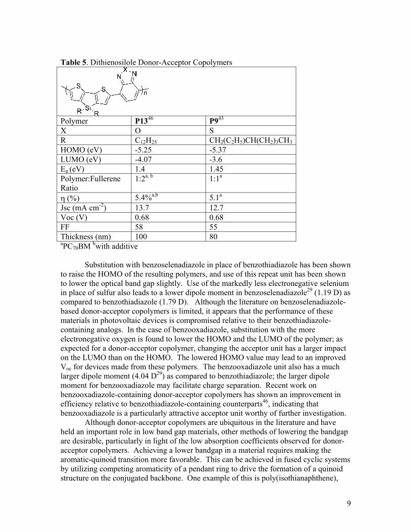
Table 5. Dithienosilole Donor-Acceptor Copolymers
Polymer P1346 P943 X O S R C12H25 CH2(C2H5)CH(CH2)3CH3 HOMO (eV) -5.25 -5.37 LUMO (eV) -4.07 -3.6 Eg (eV) 1.4 1.45 Polymer:Fullerene Ratio
1:2a, b 1:1a
η (%) 5.4%a,b 5.1a
Jsc (mA cm-2) 13.7 12.7 Voc (V) 0.68 0.68 FF 58 55 Thickness (nm) 100 80 aPC70BM bwith additive Substitution with benzoselenadiazole in place of benzothiadiazole has been shown to raise the HOMO of the resulting polymers, and use of this repeat unit has been shown to lower the optical band gap slightly. Use of the markedly less electronegative selenium in place of sulfur also leads to a lower dipole moment in benzoselenadiazole29 (1.19 D) as compared to benzothiadiazole (1.79 D). Although the literature on benzoselenadiazole-based donor-acceptor copolymers is limited, it appears that the performance of these materials in photovoltaic devices is compromised relative to their benzothiadiazole-containing analogs. In the case of benzooxadiazole, substitution with the more electronegative oxygen is found to lower the HOMO and the LUMO of the polymer; as expected for a donor-acceptor copolymer, changing the acceptor unit has a larger impact on the LUMO than on the HOMO. The lowered HOMO value may lead to an improved Voc for devices made from these polymers. The benzooxadiazole unit also has a much larger dipole moment (4.04 D29) as compared to benzothiadiazole; the larger dipole moment for benzooxadiazole may facilitate charge separation. Recent work on benzooxadiazole-containing donor-acceptor copolymers has shown an improvement in efficiency relative to benzothiadiazole-containing counterparts46, indicating that benzooxadiazole is a particularly attractive acceptor unit worthy of further investigation. Although donor-acceptor copolymers are ubiquitous in the literature and have held an important role in low band gap materials, other methods of lowering the bandgap are desirable, particularly in light of the low absorption coefficients observed for donor-acceptor copolymers. Achieving a lower bandgap in a material requires making the aromatic-quinoid transition more favorable. This can be achieved in fused cyclic systems by utilizing competing aromaticity of a pendant ring to drive the formation of a quinoid structure on the conjugated backbone. One example of this is poly(isothianaphthene),
9
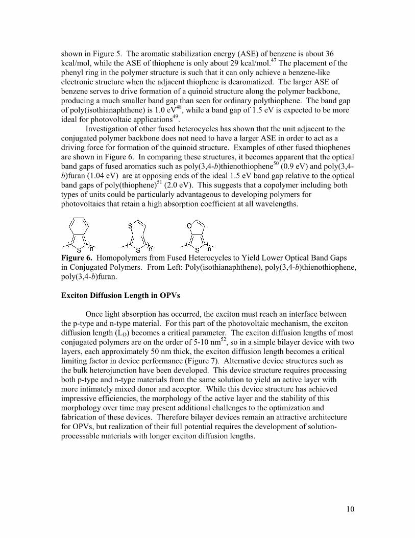
shown in Figure 5. The aromatic stabilization energy (ASE) of benzene is about 36 kcal/mol, while the ASE of thiophene is only about 29 kcal/mol.47 The placement of the phenyl ring in the polymer structure is such that it can only achieve a benzene-like electronic structure when the adjacent thiophene is dearomatized. The larger ASE of benzene serves to drive formation of a quinoid structure along the polymer backbone, producing a much smaller band gap than seen for ordinary polythiophene. The band gap of poly(isothianaphthene) is 1.0 eV48, while a band gap of 1.5 eV is expected to be more ideal for photovoltaic applications49. Investigation of other fused heterocycles has shown that the unit adjacent to the conjugated polymer backbone does not need to have a larger ASE in order to act as a driving force for formation of the quinoid structure. Examples of other fused thiophenes are shown in Figure 6. In comparing these structures, it becomes apparent that the optical band gaps of fused aromatics such as poly(3,4-b)thienothiophene50 (0.9 eV) and poly(3,4-b)furan (1.04 eV) are at opposing ends of the ideal 1.5 eV band gap relative to the optical band gaps of poly(thiophene)51 (2.0 eV). This suggests that a copolymer including both types of units could be particularly advantageous to developing polymers for photovoltaics that retain a high absorption coefficient at all wavelengths.
Figure 6. Homopolymers from Fused Heterocycles to Yield Lower Optical Band Gaps in Conjugated Polymers. From Left: Poly(isothianaphthene), poly(3,4-b)thienothiophene, poly(3,4-b)furan. Exciton Diffusion Length in OPVs Once light absorption has occurred, the exciton must reach an interface between the p-type and n-type material. For this part of the photovoltaic mechanism, the exciton diffusion length (LD) becomes a critical parameter. The exciton diffusion lengths of most conjugated polymers are on the order of 5-10 nm52, so in a simple bilayer device with two layers, each approximately 50 nm thick, the exciton diffusion length becomes a critical limiting factor in device performance (Figure 7). Alternative device structures such as the bulk heterojunction have been developed. This device structure requires processing both p-type and n-type materials from the same solution to yield an active layer with more intimately mixed donor and acceptor. While this device structure has achieved impressive efficiencies, the morphology of the active layer and the stability of this morphology over time may present additional challenges to the optimization and fabrication of these devices. Therefore bilayer devices remain an attractive architecture for OPVs, but realization of their full potential requires the development of solution-processable materials with longer exciton diffusion lengths.
10

Figure 7. Bilayer (top) and Bulk Heterojunction (bottom) Device Structures The exciton diffusion length is dependent on the exciton lifetime (τ) and the exciton diffusivity (D) according to the equation LD=(τD)1/2. The exciton lifetime is dependent on a number of parameters, one of the most critical being the spin state of the exciton. In fully organic materials, light absorption typically results in formation of a singlet excited state that has a lifetime on the order of nanoseconds. For most organic compounds, intersystem crossing to the triplet state is only weakly allowed. However, when a heavy atom is covalently attached to an organic molecule, the intersystem crossing becomes much more strongly allowed, producing materials with large triplet exciton cross-sections. This internal heavy atom effect is observed for organic compounds containing halogens such as bromine and iodine53, but is also seen for organometallic species. Organometallic complexes containing platinum54 and iridium55, in particular have been used to realize large phosphorescence quantum yields. The heavy atom effect is the result of strong spin-orbit coupling in heavy atoms. Spin-orbit coupling can be understood by considering an electron in a figure 8-like orbit (Figure 8). The electron both orbits around the nucleus and spins on an axis. As a moving, charged particle, the electron generates a magnetic field. Both the orbital motion and the spin motion generate magnetic fields around the electron. If an electron in a figure 8-like orbit is considered, at the furthest point from the nucleus, the “top” of the 8, the distance between the electron and the nucleus is large and the electron moves slowly. However, as the electron approaches the nucleus of a heavy atom, the velocity of the electron approaches the speed of light. The increase in the velocity of the charged particle produces an increase in the magnetic field. This magnetic field is a vector quantity and exerts a magnetic torque on the spin of the electron. This magnetic torque can not, by itself, flip the spin of the electron. Total angular momentum must be conserved. In a heavy atom, as the spin momentum begins to change, the orbital angular momentum begins to change as well to conserve angular momentum. This is realized in practice by the electron jumping from one orbital to another with a different orbital angular momentum – for example, jumping from a py to a px orbital. A spin flip is therefore most probable if an atom can accommodate a change in orbital geometry (e.g. py →px) at the same time as a spin flip.
11

Figure 8. Spin-Orbit Coupling Charge Separation & Transport Charge separation in organic photovoltaics is presently understood to be a two-step process. An exciton that has both δ+ and δ- on either the donor or the acceptor is then split across the donor and the acceptor, forming a neutral species where the δ+ charge is localized on the donor material and the δ- charge is localized on the acceptor material. This exciton is often referred to as a geminate pair or the charge separated state. Given that the hole and the electron are still correlated to one another, an exciton with a triplet spin state may be advantageous to inhibiting recombination of the geminate pair to the ground state. This geminate pair lies in a potential well (Figure 9) and experiences an energetic barrier to formation of the fully charge separated state. This represents a significant departure from the behavior of inorganic semiconductors, which generate free charge carriers directly upon photoexcitation. While decay from the geminate pair to the ground state represents a significant loss mechanism in photovoltaic devices, charge separation is the desired process56. When charge separation occurs, the radical cation of the donor and the radical anion of the acceptor are formed. Charge transport occurs under the influence of the electric field in the device, and happens via a hopping mechanism57.
Figure 9. Reaction coordinate for charge separation in organic photovoltaics Summary & Outlook π-conjugated small molecules and polymers represent an attractive route to inexpensive electronic devices. Photovoltaic devices in particular are appealing given the
12

abundance of energy from the sun and the need for a clean, independent source of energy. Furthering the performance of these devices must rely on an improved understanding of the fundamental mechanism of photocurrent production, as guided by the study of novel materials designed to alter and enhance those same mechanisms. Through an iterative process, going from fundamental device operation to material design to device testing back to fundamental device operation, structure-property relationships of conjugated molecules can be developed. The following chapters present research into fundamental design principles that can guide the further development of new materials as well as advance the present understanding of the photovoltaic mechanism. References 1. Chiang, C. K.; Druy, M. A.; Gau, S. C.; Heeger, A. J.; Louis, E. J.; MacDiarmid,
A. G.; Park, Y. W.; Shirakawa, H. J. Am. Chem. Soc. 1978, 100, 1013-1015. 2. Chou, P.; Chi, Y. Chem. Eur. J. 2007, 13, 380-395. 3. Osaka, I.; McCullough, R. D. Acc. Chem. Res. 2008, 41, 1202-1214. 4. Mühlbacher, D.; Scharber, M.; Morana, M.; Zhu, Z.; Waller, D.; Gaudiana, R.;
Brabec, C. Adv. Mater. 2006, 18, 2884-2889. 5. Ma, B.; Kim, B. J.; Deng, L.; Poulsen, D. A.; Thompson, M. E.; Frechet, J. M. J.
Macromolecules 2007, 40, 8156-8161. 6. Thompson, B.; Fréchet, J. Angew. Chem. Int. Ed. 2008, 47, 58-77. 7. Villani, F.; Vacca, P.; Nenna, G.; Valentino, O.; Burrasca, G.; Fasolino, T.;
Minarini, C.; della Sala, D. J. Phys. Chem. C 2009, 113, 13398-13402. 8. Calvert, P. Chem. Mater. 2001, 13, 3299-3305. 9. Hanket, G. M.; Birkmire, R. W.; Jackson, S. C.; Rocheleau, R. E. Ind. Eng. Chem.
Res. 2009, 48, 5923-5933. 10. Krebs, F. C.; Norrman, K. ACS Appl. Mater. & Int. 2010, 2, 877-887. 11. Kietzke, T.; Egbe, D. A. M.; Horhold, H.; Neher, D. Macromolecules 2006, 39,
4018-4022. 12. Kim, B. J.; Miyamoto, Y.; Ma, B.; Fréchet, J. M. J. Adv. Funct. Mater. 2009, 19,
2273-2281. 13. Liu, J.; Kadnikova, E. N.; Liu, Y.; McGehee, M. D.; Frechet, J. M. J. J. Am. Chem.
Soc. 2004, 126, 9486-9487. 14. McNeill, C. R.; Halls, J. J. M.; Wilson, R.; Whiting, G. L.; Berkebile, S.; Ramsey,
M. G.; Friend, R. H.; Greenham, N. C. Adv. Funct. Mater. 2008, 18, 2309-2321. 15. van Duren, J. K. J.; Dhanabalan, A.; van Hal, P. A.; Janssen, R. A. J. Synth. Met.
2001, 121, 1587-1588. 16. Ohkita, H.; Cook, S.; Astuti, Y.; Duffy, W.; Tierney, S.; Zhang, W.; Heeney, M.;
McCulloch, I.; Nelson, J.; Bradley, D. D. C.; Durrant, J. R. J. Am. Chem. Soc. 2008, 130, 3030-3042.
17. Chen, J.; Cao, Y. Acc. Chem. Res. 2009, 42, 1709-1718. 18. Mondal, R.; Miyaki, N.; Becerril, H. A.; Norton, J. E.; Parmer, J.; Mayer, A. C.;
Tang, M. L.; Brédas, J.; McGehee, M. D.; Bao, Z. Chem. Mater. 2009, 21, 3618-3628.
19. Mondal, R.; Ko, S.; Norton, J. E.; Miyaki, N.; Becerril, H. A.; Verploegen, E.; Toney, M. F.; Brédas, J.; McGehee, M. D.; Bao, Z. J. Mater. Chem. 2009, 19,
13

7195-7197. 20. Park, S. H.; Roy, A.; Beaupre, S.; Cho, S.; Coates, N.; Moon, J. S.; Moses, D.;
Leclerc, M.; Lee, K.; Heeger, A. J. Nat. Photon. 2009, 3, 297-302. 21. Chen, C.; Hsieh, C.; Dubosc, M.; Cheng, Y.; Hsu, C. Macromolecules 2010, 43,
697-708. 22. Helgesen, M.; Krebs, F. C. Macromolecules 2010, 43, 1253-1260. 23. Karsten, B. P.; Viani, L.; Gierschner, J.; Cornil, J.; Janssen, R. A. J. J. Phys.
Chem. A 2009, 113, 10343-10350. 24. Wang, X.; Wong, W.; Cheung, K.; Fung, M.; Djurisic, A. B.; Chan, W. Dalton
Trans. 2008, 5484-5494. 25. Moulé, A. J.; Tsami, A.; Bünnagel, T. W.; Forster, M.; Kronenberg, N. M.;
Scharber, M.; Koppe, M.; Morana, M.; Brabec, C. J.; Meerholz, K.; Scherf, U. Chem. Mater. 2008, 20, 4045-4050.
26. Tsai, J.; Chueh, C.; Lai, M.; Wang, C.; Chen, W.; Ko, B.; Ting, C. Macromolecules 2009, 42, 1897-1905.
27. Liu, C.; Tsai, J.; Lee, W.; Chen, W.; Jenekhe, S. A. Macromolecules 2008, 41, 6952-6959.
28. Qian, G.; Zhong, Z.; Luo, M.; Yu, D.; Zhang, Z.; Ma, D.; Wang, Z. Y. J. Phys. Chem. C. 2009, 113, 1589-1595.
29. Tobiason, F. L.; Huestis, L.; Chandler, C.; Pedersen, S. E.; Peters, P. J. Heterocycl. Chem. 1973, 10, 773-778.
30. Lumbroso, H.; Curé, J.; Konakahara, T.; Takagi, Y. J.Mol. Struct. 1980, 68, 293-305.
31. Svensson, M.; Zhang, F.; Veenstra, S.; Verhees, W.; Hummelen, J.; Kroon, J.; Inganäs, O.; Andersson, M. Adv. Mater. 2003, 15, 988-991.
32. Veldman, D.; Ìpek, O.; Meskers, S. C. J.; Sweelssen, J.; Koetse, M. M.; Veenstra, S. C.; Kroon, J. M.; Bavel, S. S. V.; Loos, J.; Janssen, R. A. J. J. Am. Chem. Soc. 2008, 130, 7721-7735.
33. Blouin, N.; Michaud, A.; Gendron, D.; Wakim, S.; Blair, E.; Neagu-Plesu, R.; Belletete, M.; Durocher, G.; Tao, Y.; Leclerc, M. J. Am. Chem. Soc. 2007, 130, 732-742.
34. Blouin, N.; Michaud, A.; Leclerc, M. Adv. Mater. 2007, 19, 2295-2300. 35. Wakim, S.; Beaupre, S.; Blouin, N.; Aich, B.; Rodman, S.; Gaudiana, R.; Tao, Y.;
Leclerc, M. J. Mater. Chem. 2009, 19, 5351-5358. 36. Wang, E.; Wang, L.; Lan, L.; Luo, C.; Zhuang, W.; Peng, J.; Cao, Y. Appl. Phys.
Lett. 2008, 92, 033307. 37. Moulé, A. J.; Tsami, A.; Bünnagel, T. W.; Forster, M.; Kronenberg, N. M.;
Scharber, M.; Koppe, M.; Morana, M.; Brabec, C. J.; Meerholz, K.; Scherf, U. Chem. Mater. 2008, 20, 4045-4050.
38. Zhou, E.; Nakamura, M.; Nishizawa, T.; Zhang, Y.; Wei, Q.; Tajima, K.; Yang, C.; Hashimoto, K. Macromolecules 2008, 41, 8302-8305.
39. Zhang, X.; Steckler, T. T.; Dasari, R. R.; Ohira, S.; Potscavage Jr., W. J.; Tiwari, S. P.; Coppee, S.; Ellinger, S.; Barlow, S.; Bredas, J.; Kippelen, B.; Reynolds, J. R.; Marder, S. R. J. Mater. Chem. 2010, 20, 123-134.
40. Huo, L.; Chen, H.; Hou, J.; Chen, T. L.; Yang, Y. Chem. Commun. 2009, 5570-5572.
14

15
41. Lee, J. K.; Ma, W. L.; Brabec, C. J.; Yuen, J.; Moon, J. S.; Kim, J. Y.; Kwanghee Lee; Bazan, G.C.; Heeger, A. J. J. Am. Chem. Soc. 2008, 130, 3619.
42. Yue, W.; Zhao, Y.; Shao, S.; Tian, H.; Xie, Z.; Geng, Y.; Wang, F. J. Mater. Chem. 2009, 19, 2199-2206.
43. Hou, J.; Chen, H.; Zhang, S.; Li, G.; Yang, Y. J. Am. Chem. Soc. 2008, 130, 16144-16145.
44. Coates, N. E.; Hwang, I.; Peet, J.; Bazan, G. C.; Moses, D.; Heeger, A. J. Appl. Phys. Lett. 2008, 93, 072105.
45. Bijleveld, J. C.; Shahid, M.; Gilot, J.; Wienk, M. M.; Janssen, R. A. J. Adv. Funct. Mater. 2009, 19, 3262-3270.
46. Hoven, C. V.; Dang, X.; Coffin, R. C.; Peet, J.; Nguyen, T.; Bazan, G. C. Adv. Mater. 9999, NA.
47. Wheland, G. Resonance in Organic Chemistry; Wiley: NY, 1955. 48. Tada, K.; Morita, S.; Yoshino, K.; Onoda, M.; Zakhidov, A. A. Synth. Met. 1995,
70, 1347-1348. 49. Scharber, M. C.; Mühlbacher, D.; Koppe, M.; Denk, P.; Waldauf, C.; Heeger, A.
J.; Brabec, C. J. Adv. Mater. 2006, 18, 789-794. 50. Lee, K.; Sotzing, G. A. Macromolecules 2001, 34, 5746-5747. 51. McCullogh, R. D.; Williams, S. P.; Tristam-Nagle, S.; Jayaraman, M.; Ewbank, P.
C.; Miller, L. Synth. Met. 1995, 69, 279-282. 52. Scully, S. R.; Armstrong, P. B.; Edder, C.; Fréchet, J. M. J.; McGehee, M. D. Adv.
Mater. 2007, 19, 2961-2966. 53. Kasha, M. J. Chem. Phys. 1952, 20, 71-74. 54. Cho, J.; Suponitsky, K. Y.; Li, J.; Timofeeva, T. V.; Barlow, S.; Marder, S. R. J.
Organomet. Chem. 2005, 690, 4090-4093. 55. Lamansky, S.; Djurovich, P.; Murphy, D.; Abdel-Razzaq, F.; Kwong, R.; Tsyba,
I.; Bortz, M.; Mui, B.; Bau, R.; Thompson, M. E. Inorg. Chem. 2001, 40, 1704-1711.
56. Blom, P. W. M.; Mihailetchi, V. D.; Koster, L. J. A.; Markov, D. E. Adv. Mater. 2007, 19, 1551-1566.
57. Tessler, N.; Preezant, Y.; Rappaport, N.; Roichman, Y. Adv. Mater. 2009, 21, 2741-2761.

Chapter 2: Thieno[3,4-b]thiophene – Based Small Molecules for Organic Photovoltaics Abstract The synthesis, optoelectronic properties, and photovoltaic performance of a small molecule containing a thieno[3,4-b]thiophene unit is presented. When the thieno[3,4-b]thiophene is incorporated into a pentathiophene analog, the absorption spectrum of the compound exhibits a dramatic redshift relative to a soluble pentathiophene derivative that only incorporates thiophene units. The optical band gap of the fused pentathiophene analog is 1.8 eV, which is comparable to polythiophenes. Photovoltaic efficiencies approaching 1.9% have been achieved with this small molecule in bulk heterojunction devices with PC70BM. Introduction Organic semiconductors offer the potential for inexpensive, solution processable devices such as solar cells1. Significant research has been focused on developing and optimizing conjugated polymers as donor materials to pair with a fullerene acceptor, but recent work has shown significant advances in the area of solution processable small molecules as well.2-4 Solution processable small molecules may be particularly advantageous to the development organic electronics as batch to batch variations should be minimized as compared to polymeric materials. Efficiencies as high as 4.4% in small molecule cells5 demonstrate that small molecules have the potential to achieve performances comparable to those of conjugated polymers. One critical property of these materials requiring optimization is light absorption. Given that the conjugation length of a small molecule is generally much smaller than the effective conjugation length of a corresponding semiconducting polymer, the light absorption of these small molecules can be compromised relative to their polymeric counterparts. Utilizing a donor-acceptor approach can redshift light absorption, but can also lead to decreased absorption coefficients in conjugated molecules.6 Together, these observations indicate that a means to redshift the absorption spectrum without adversely affecting the absorption coefficient of a conjugated small molecule is necessary to further enhance the performance of these materials. Conjugated polymers based on thieno[3,4-b]thiophene (Figure 1) have been shown to have a redshifted absorption relative to thiophene-based materials.7-11 This redshift in absorption is believed to arise from a competition between the fused thiophene units for an aromatic structure. The aromatization of the thiophene unit that is adjacent to the conjugated backbone acts as a driving force for the formation of a quinoid form on the rest of the molecule. Given that this approach is expected to result in minimal localization of the HOMO and LUMO of the molecule, the barrier to formation of an excited state is expected to be low and the absorption coefficient is therefore expected to be high. Fused aromatic systems utilizing this approach are expected to show a redshifted absorption spectrum relative to the non-fused counterparts, and are furthermore expected to retain high absorption coefficients. This work presents the
16

synthesis and optoelectronic properties of a thieno[3,4-b]thiophene-based small molecule, and its application to photovoltaic devices.
Figure 1. Structure of poly(thieno[3,4-b]thiophene) Results and Discussion Synthesis The structure of the thieno[3,4-b]thiophene-based small molecule, TT-5T, is shown in figure 2, and the synthesis of this molecule is shown in Scheme 1. The small molecule is readily prepared from a Stille coupling between a stannylated bithiophene and a dibrominated thieno[3,4-b]thiophene ester. The electron-withdrawing ester stabilizes the electron-rich thieno[3,4-b]thiophene system.
Figure 2. Structure of TT-5T
17

Scheme 1. Synthesis of TT-5T
Optoelectronic Properties The optoelectronic properties of TT-5T were studied in order to determine the suitability of this small molecule for photovoltaic applications. The absorption spectra in chloroform solution and in a thin film are shown in Figure 3. The solution spectrum shows an absorption peak at 501 nm, showing a considerable redshift as compared to a soluble pentathiophene with an absorption peak at 403 nm12. This redshift of nearly 100 nm indicates the considerable capacity of the thienothiophene unit to drive the oligothiophene to a quinoid structure. The absorption spectrum in a thin film shows the same maximum, but Cyclic voltammetry indicates that TT-5T has an onset of oxidation at -5.4 eV relative to vacuum. This data taken together with the solid-state absorption spectrum indicates that the LUMO of TT-5T is at -3.6 eV relative to vacuum. Given that the LUMO of PC60BM and PC70BM are typically taken to be between -3.9 and -4.1 eV, the LUMO of TT-5T is expected to provide more than sufficient offset for efficient charge separation.
18

Figure 3. Absorption Spectra of TT-5T in CHCl3 Solution (red) & Thin Film (black) Photovoltaic Devices Photovoltaic devices were fabricated from blends of TT-5T and PC70BM. The devices were optimized for blend ratio and annealing conditions. The best efficiency is found with a 1:4 TT-5T:PC70BM ratio, with an average efficiency of 1.6% over eight devices, with a peak efficiency of 1.86% using a Ca/Al electrode. This maximum power conversion efficiency corresponds to a fill factor of 0.36, a Voc of 0.75 V, and a Jsc of 6.87 mA cm-2. The current-voltage curve of this device is shown in Figure 4.
Figure 4. Photovoltaic Devices: TT-5T:PC70BM Blend with Ca/Al electrodes
19
Conclusions This work demonstrates the synthesis of a pentathiophene analog containing a thieno[3,4-b]thiophene unit, and its application to organic solar cells. Notably, the absorption spectrum of this small molecule is redshifted by nearly 100 nm relative to a soluble pentathiophene derivative. This redshift occurs in both solution and the solid state indicating that the redshift is not merely a result of improved packing but is rather the result of the thienothiophene unit inducing dearomatization of the small molecule backbone. This approach to tuning light absorption is expected to be particularly advantageous considering that the redshift occurs without relying on donor-acceptor systems, which lower the absorption coefficients of the resulting material. Photovoltaic efficiencies as high as 1.86% are achieved with this molecule in bulk heterojunction devices with PC70BM, indicating that small molecules utilizing the thienothiophene moiety present a promising new route to increasing light absorption in small molecules for organic solar cells. Future work in this area will focus on further tuning the spectral overlap and optical density of these materials by modifying the nature and placement of solubilizing groups, and by modifying the structure of the aromatic units adjancent to the thienothiophene moiety. Experimental Synthesis
All chemicals were purchased from commercial sources and used without
purification unless otherwise stated. Tetrahydrofuran (THF), dichloromethane (DCM), N, N-dimethylformamide (DMF), and toluene were dried by passing through neutral alumina prior to use. All small molecules were characterized by 1H NMR (400 or 500 MHz) and 13C NMR (100 or 125 MHz) on a Bruker AVQ 400 or DRX 500 as specified. All NMR spectra were referenced to TMS. High-resolution mass spectroscopy and elemental analysis (CHN) were performed at the University of California, Berkeley Department of Chemistry analytical services laboratory. Melting points are uncorrected. Column chromatography was performed with silica (230x400 mesh).
Methyl 4,5-bis(chloromethyl)thiophene-2-carboxylate (2): 2-thiophene carboxylic acid methyl ester (10 g, 70.3 mmol, 1 eq) was dissolved in chloromethyl methyl ether (60 mL) and the solution cooled to 0oC. To this solution was added TiCl4 (23 mL, 210.9 mmol, 3 eq) dropwisely. After the addition was complete, the solution was kept at 0oC for an additional 20 minutes then the ice bath removed and the reaction allowed to warm to room temperature. The solution continued to stir and after two hours the reaction mixture was poured slowly over ice. Dichloromethane was added and the organic layer washed with water until both layers were colorless. The dichloromethane layer was dried with sodium sulfate, the sodium sulfate removed by filtration and solvent removed under reduced pressure to yield the product as a white solid with m.p. 72-75oC in 97% yield. 1H NMR (400 MHz, CDCl3) δ 7.71 (s, 1H), 4.78 (s, 2H), 4.59 (s, 2H), 3.89 (s, 3H). 13C (100 MHz, CDCl3) δ 161.94, 143.92, 137.15, 134.94, 132.95, 52.55, 37.52, 37.21. CHN
20

Calcd. 40.18% C, 3.37% H, found 40.41% C, 3.01% H. HRMS (EI) Calcd. 237.9629, Found 237.9622.
Methyl 4H,6H-thieno[2,3-c]thiophene-2-carboxylate (3): In a three-necked flask equipped with a reflux condenser and addition funnel, 2 (6.65 g, 27.8 mmol, 1 eq) was dissolved in 300 mL methanol. In a separate flask, sodium sulfide (2.26 g, 28.9 mmol, 1.04 eq) was dissolved in 200 mL methanol. The solution of 2 was heated to 65oC, and the sodium sulfide solution was added dropwise to the gently refluxing solution of 2. After the addition of the sodium sulfide solution was complete, the reaction was heated to reflux for an additional five hours. The reaction was then cooled to room temperature and concentrated under reduced pressure to yield 100 mL of solution. The concentrated reaction mixture was then poured over rapidly stirring ice water and allowed to stir overnight. The following day the product was collected as an off-white solid with m.p. 99-102oC in 87% yield. 1H NMR (400 MHz, DMSO-D6) δ 7.52 (s, 1H), 4.15 (t, 2H), 3.98 (t, 2H), 3.56 (s, 3H). 13C (100 MHz, DMSO-D6) δ 162.26, 147.09, 144.61, 136.59, 128.79, 52.65, 33.15, 32.75. HRMS (EI+) for C8H8O2S2 Calcd. 199.9966, found 199.9969. CHN Calcd. 47.98% C, 4.03% H, found 47.94% C, 3.67% H.
4H,6H-thieno[2,3-c]thiophene-2-carboxylic acid (4): Potassium hydroxide (2.0 g, 35.8 mmol, 2 eq) was dissolved in 100 mL water. To this solution was added 3 (3.59 g, 17.92 mmol, 1 eq), and the reaction mixture was heated to reflux overnight. The next day, the reaction was filtered to remove unreacted ester, and then the filtrate acidified to precipitate the carboxylic acid 4 as a tan solid with m.p. 214-216oC (dec.) in 64% yield. 1H NMR (400 MHz, DMSO-D6) δ 7.2 (s, 1H), 4.2 (s, 2H), 4.4 (s, 2H). HRMS (EI+) for C7H6O2S2 calcd. 185.9808, found 185.9809. CHN Calcd. 45.14% C, 3.25% H, found 44.20% C, 3.37% H.
5-Oxo-5,6-dihydro-4H-5λ4-thieno[3,4-b]thiophene-2-carboxylic acid (5): To 30 mL of water was added sodium periodate (2.89 g, 13.53 mmol, 1.2 eq) and the solution was cooled to 0oC. To this solution was added 4 (2.1 g, 11.27 mmol, 1 eq) in one portion, and sodium carbonate (1.34 g, 12.62 mmol, 1.12 eq) in several portions. The reaction was kept at 0oC and allowed to warm to room temperature slowly overnight. The next day the reaction was filtered and then acidified to precipitate the product, which was then collected by filtration to yield a pale tan solid with m.p. 184-186oC (dec.) in 85% yield. 1H NMR (400 MHz, DMSO-D6) δ 7.45 (s, 1H), 4.1 (s, 2H), 4.35 (s, 2H). HRMS (EI+) for C7H6O3S2 calcd. 201.9758, found 201.9761. CHN Calcd. 41.57% C, 2.99% H, found 40.53% C, 2.52% H.
Thieno[3,4-b]thiophene-2-carboxylic acid (6): In a dry three-neck flask 5 (1.0 g, 4.94 mmol, 1 eq) was dissolved in acetic anhydride to form a 0.28 M solution. The solution was degassed by three cycles of freeze-pump-thaw and then heater to reflux for 2.5 hours. The solution was then cooled to room temperature and the solvent removed under reduced pressure. After removal of the solvent, the flask was cooled to 0oC and 10 mL THF and 10 mL of a 1 M NaOH solution were added to the reaction mixture. The solution was allowed to stir overnight, slowly warming to room temperature. The product was isolated by removing the THF under reduced pressure and acidifying the
21

aqueous layer. The product was then extracted into ethyl acetate, the organic layers combined, dried, and the solvent removed under reduced pressure to yield the product as a brown solid with m.p. 181-184oC in 65% yield. 1H NMR (400 MHz, DMSO-D6) δ 7.35 (d, 1H), 7.12 (s, 1H), 7.09 (d, 1H). 13C NMR (100 MHz, DMSO-D6) δ 164.42, 146.06, 140.62, 138.95, 124.01, 118.66, 113.12. HRMS (EI+) for C7H4O2S2 Calcd. 183.9653, Found 183.9655. CHN Calcd. 45.63% C, 2.19% H. Found 45.37% C, 2.52% H.
4,6-dibromothieno[3,4-b]thiophene-2-carboxylic acid (7): In a dry flask under nitrogen and in the dark, carboxylic acid 6 (0.55 g, 2.99 mmol, 1 eq) was dissolved in DMF to yield a 0.7 M solution. In a separate flask, N-bromosuccinimide (1.17 g, 6.57 mmol, 2.2 eq) was dissolved in DMF to yield a 1.6 M solution. The solution of N-bromosuccinimide was added to the carboxylic acid solution dropwise and the reaction mixture heated to 40oC overnight in the dark. The next day, the reaction was cooled to room temperature and poured over an aqueous solution of sodium bisulfite at 0oC. The reaction was filtered to yield the product as a brown solid in 38% yield. 1H NMR (400 MHz, DMSO-D6) δ 7.59 (s, 1H). LRMS (EI+) for C7H2Br2O2S2 calcd. 342, found 342.
3,7-dimethyloctyl 4,6-dibromothieno[3,4-b]thiophene-2-carboxylate (1): 4,6-dibromothieno[3,4-b]thiophene-2-carboxylic acid (0.350 g, 1.02 mmol, 1 eq) was dissolved in anhydrous dichloromethane (5 mL). To this solution was added 3,7-dimethyl-1-octanol (0.807 g, 5.1 mmol, 5 eq),4-(dimethylamino)pyridine (0.045 g, 0.36 mmol, 0.35 eq), and N,N′-dicyclohexylcarbodiimide (0.252 g, 1.22 mmol, 1.2 eq). The solution was stirred overnight at room temperature, and filtered and washed with dichloromethane the following day. The filtrate was concentrated and applied to a silica column (10% ethyl acetate in hexanes) and the product eluted as the top spot to give a reddish oil in 65% yield. 1H NMR (400 MHz, CDCl3) δ 7.53 (s, 1H), 4.35 (t, 2H), 1.77 (m, 1H), 1.56 (m, 1H), 1.30 (m, 2H), 1.16 (m, 2H), 0.94 (m, 3H), 0.87 (m, 6H). 13C NMR (100 MHz, CDCl3) δ 162.36, 145.56, 141.09, 140.40, 123.14, 102.21, 97.10, 64.64, 37.05, 35.35, 29.86, 27.93, 24.58, 22.68, 22.58, 19.56. 3,7-dimethyloctyl 4,6-bis[5-(thiophen-2-yl)thiophen-2-yl]thieno[3,4-b]thiophene-2-carboxylate (TT-5T): 3,7-dimethyloctyl 4,6-dibromothieno[3,4-b]thiophene-2-carboxylate (0.200 g, 0.415 mmol, 1 eq) was dissolved in a mixture of toluene (3 mL) and DMF (1 mL). To this solution was added trimethyl[5-(thiophen-2-yl)thiophen-2-yl]stannane (0.314 g, 0.954 mmol, 2.3 eq) and palladium (0) tetrakis(triphenylphosphine) (10 mg, 0.008 mmol, 0.02 eq). The solution was purged with nitrogen for 20 minutes, and heated to 100oC overnight. The solution was cooled to room temperature and the reaction mixture poured into methanol to precipitate the crude product. The solid was then redissolved in dichloromethane, filtered through celite, and reprecipitated into methanol to give the product as a dark red solid in 73% yield. 1H NMR (500 MHz, CDCl3) δ 7.90 (s, 1H), 7.24 (m, 2H), 7.19 (dd, 2H), 7.07 (m, 6H), 4.37 (d, 2H), 1.83 (d, 1H), 1.57 (m, 3H), 1.33 (m, 3H), 1.18 (m, 3H), 0.98 (d, 3H), 0.87 (d, 6H). 13C NMR (126 MHz, CDCl3) δ 162.71, 141.37, 140.19, 137.70, 136.91, 136.86, 136.72, 136.08, 134.10, 134.06, 128.06, 127.99, 126.89, 125.42, 124.95, 124.72, 124.56, 124.50, 124.35, 124.07, 123.90, 121.27, 64.63, 39.23, 37.19, 35.51, 30.04, 28.00, 24.70, 22.76, 22.67,
22

19.69. HRMS (FAB) calcd. for C33H32O2S6 652.0727, found 652.0725. CHN Calcd. 60.70% C, 4.94% H. Found 59.91% C, 4.85% H. Trimethyl[5-(thiophen-2-yl)thiophen-2-yl]stannane (3): 2,2′-Bithiophene (3.99 g, 24 mmol, 1 eq) was dissolved in anhydrous THF (150 mL) and cooled to -78oC. To this solution was added 9.6 mL of a 2.5 M solution of n-butyllithium (24 mmol, 1 eq). The reaction was allowed to stir at -78oC for one hour, and then 24 mL of a 1.0 M solution of trimethyltin chloride (24 mmol, 1 eq) was added. The reaction was allowed to warm to room temperature overnight, and the following day the reaction mixture was poured over aqueous 1M potassium hydroxide. The product was extracted into ether, the organic layers combined and dried with magnesium sulfate, then the magnesium sulfate removed by filtration. The solvent was removed by rotary evaporation to yield the product as a tan oil in 62% yield. 1H NMR (400 MHz, CDCl3) δ 7.27 (d, 1 H), 7.16 (m, 2H), 7.08 (d, 1H), 6.99 (dd, 1H), 0.37 (m, 9H). 13C NMR (101 MHz, CDCl3) δ 143.0, 137.6, 137.2, 136.0, 127.9, 125.1, 124.3, 123.7, -8.1. CHN Calcd. 40.15% C, 4.29% H. Found 39.87% C, 4.09% H. LRMS (EI+) for C11H14S2Sn calcd, 342, found 342. Optical and Electronic Characterization
Cyclic voltammetry (CV) was performed using a Solartron 1285 potentiostat. The cyclic voltammograms were measured in dichloromethane solution with a Pt wire working electrode. All measurements were performed using a silver wire pseudo-reference electrode, a platinum auxiliary electrode, and were referenced to the ferrocene/ferrocenium couple, which was taken to be -5.1 eV relative to vacuum.13 Tetrabutylammonium tetrafluoroborate (NBu4BF4) was the supporting electrolyte for all measurements. UV-Visible absorption spectra were obtained using a Cary 50 UV-Visible spectrophotometer. For thin film measurements the small molecule was spin coated onto untreated glass slides from chloroform solution (10 mg mL-1). A model P6700 Spincoater was used to spin coat the films at 1500 rpm for 60 s.
Photovoltaic Devices
Bulk heterojunction photovoltaic devices consisted of a standard ITO/PEDOT:PSS/TT-5T:PC70BM/Al or Ca/Al architecture. Indium-doped tin oxide (ITO) coated glass substrates were purchased from Thin Film Devices, Inc. The substrates (150 nm sputtered pattern, 10 Ω -1) were cleaned by 20 minutes of sonication in acetone, 2 percent Helmanex soap in water, and finally isopropanol. The substrates were then dried under a stream of air before being coated immediately with a filtered (0.45 μm GHP) dispersion of PEDOT:PSS in water (Baytron-PH) via spin coating for 30 s at 4000 rpm. The resulting polymer layer was ~30 nm thick after baking at 140 °C for 20 min. All subsequent device fabrication was performed inside a glove box under inert Ar atmosphere with water and oxygen levels below 1 ppm. The small molecule was dissolved in chloroform at a concentration of 40 mg mL-1. PCBM (purchased from Nano-C) was dissolved separately at 40 mg mL-1 in chloroform and all solutions were allowed to stir overnight. The solutions were then combined in various ratios from 1:1 to 1:6 TT-5T:PCBM before spin casting onto the PEDOT:PSS-treated ITO at 1200 rpm for 30
23
24
seconds. For the best devices the final concentration of TT-5T is 8 mg/mL in chloroform. 100 nm aluminum electrodes or calcium and aluminum electrodes were deposited by thermal resistance evaporation at pressures of approximately 10-6 torr to complete the device structure. The shadow mask used during thermal deposition yielded eight independent devices per substrate each with a surface area of 0.03 cm2. Completed devices were then tested under Ar(g) using a 300 W Thermo-Oriel Xenon arc-lamp with flux control spectrally corrected to AM 1.5 G with one filter (Thermo-Oriel #81088). The AM 1.5 G light was further attenuated using a 0.5 O.D. neutral density filter, and the intensity of the AM 1.5 G light was calibrated to be 100 mW cm-2 by a spectrally-matched Hamamatsu S1787-04 photodiode (calibrated by NREL and obtained through Nanosys Inc.). I-V behavior was measured using a computer-controlled Keithley 236 SMU.
References 1. Thompson, B.; Fréchet, J. Angew. Chem. Int. Ed. 2008, 47, 58-77. 2. Lloyd, M. T.; Anthony, J. E.; Malliaras, G. G. Materials Today 2007, 10, 34-41. 3. Ma, B.; Woo, C. H.; Miyamoto, Y.; Fréchet, J. M. J. Chem. Mater. 2009, 21, 1413-1417. 4. Peet, J.; Tamayo, A. B.; Dang, X. D.; Seo, J. H.; Nguyen, T. Q. Appl. Phys. Lett. 2008, 93, 163306-3. 5. Walker, B.; Tamayo, A. B.; Dang, X.; Zalar, P.; Seo, J. H.; Garcia, A.; Tantiwiwat, M.; Nguyen, T. Adv. Funct. Mater. 2009, 19, 3063-3069. 6. Mondal, R.; Ko, S.; Norton, J. E.; Miyaki, N.; Becerril, H. A.; Verploegen, E.; Toney, M. F.; Bredas, J.; McGehee, M. D.; Bao, Z. J. Mater. Chem. 2009, 19, 7195-7197. 7. Yao, Y.; Liang, Y.; Shrotriya, V.; Xiao, S.; Yu, L.; Yang, Y. Adv. Mater. 2007, 19, 3979-3983. 8. Lee, K.; Sotzing, G. A. Macromolecules 2001, 34, 5746-5747. 9. Sotzing, G. A.; Lee, K. Macromolecules 2002, 35, 7281-7286. 10. Lee, B.; Yavuz, M. S.; Sotzing, G. A. Macromolecules 2006, 39, 3118-3124. 11. Liang, Y.; Wu, Y.; Feng, D.; Tsai, S.; Son, H.; Li, G.; Yu, L. J. Am. Chem. Soc. 2009, 131, 56-57. 12. Fujitsuka, M.; Harada, K.; Sugimoto, A.; Majima, T. J. Phys. Chem. A 2008, 112, 10193-10199. 13. Pavlishchuk, V. V.; Addison, A. W. Inorg. Chim. Act. 2000, 298, 97-102
Chapter 3: Cyclometalated Platinum Polymers for Bilayer Photovoltaics Abstract The platinum-containing cyclometalated polymer F8PPyPt and its unmetalated analog F8Py were studied in bilayer photovoltaic devices with titania acceptors in order to determine the influence of the platinum center on photocurrent production. The platinum atom induces strong spin-orbit coupling, making F8PPyPt a phosphorescent, rather than a fluorescent, conjugated polymer. The current density produced in the F8PPyPt device is more than four times greater than the unmetalated F8Py at Jsc. This increase in photocurrent can not be fully explained by differences in light absorption, indicating that inducing triplet formation in conjugated polymers via attachment of heavy atoms such as platinum is an attractive route to increasing the exciton diffusion length of these materials. Introduction Semiconducting polymers potentially offer an attractive alternative to inorganic semiconductors in electronic devices such as light emitting diodes, transistors, and photovoltaics. Most organic materials used in photovoltaic devices form primarily singlet excitons, which possess short lifetimes in the nanosecond regime. Given that exciton diffusion length (LD) is related to exciton lifetime (τ) and exciton diffusivity (D) according to the equation DLD τ= , increasing the lifetime of the exciton should lead to a significant increase in the exciton diffusion length. Presently most conjugated polymers have exciton diffusion lengths on the order of 5-10 nm.1, 2 The exciton must reach an interface between p-type and n-type materials in order to split into free charge carriers. However, achieving a stable domain spacing between a donor and acceptor on the order of 5-10 nm can be extremely challenging.3 The large interfacial area between p-type and n-type material in a bulk heterojunction photovoltaic device also means that charge transport is significantly more disordered in these systems than for a bilayer device, and the potential for bimolecular charge recombination is increased.4 Triplet excitons generally have a lifetime on the order of microseconds, but do not typically form in fully organic materials. The intersystem crossing yield for an organic material can be greatly enhanced by the presence of heavy atoms such as platinum and iridium.5, 6 Spin-orbit coupling allows for greater mixing between singlet and triplet states in an organic material that incorporates these heavy atoms. If the lifetime of an exciton were to be increased from the nanosecond regime into the microsecond regime, it can be anticipated that such an exciton will have a diffusion length on the order of ~150 nm, assuming the diffusivity remains constant. Even if the diffusivity of the exciton decreases by an order of magnitude, the increased diffusion length (~50 nm) should provide a significant advantage to photocurrent generation in a bilayer photovoltaic device. Photovoltaic devices using evaporated small molecules present significant evidence that increasing the lifetime of an exciton can increase the diffusion length, and therefore increase the photocurrent. Work by Terao et al has demonstrated a positive correlation between excited state lifetime and Jsc in a bilayer device in evaporated
25

phthalocyanine/C60 devices.7 Further, time-dependent photocurrent studies indicate that a palladium-containing porphyrin derivative produces increased photocurrent relative to unmetalated analogs, and that this photocurrent increases over a longer period of time, indicating that long-lived excitons are contributing to device operation.8 In order for the advantages associated with increasing exciton diffusion length to be fully realized in organic photovoltaics, triplet-forming materials need to be developed that are solution processable. Conjugated polymers present an attractive route to developing a solution processable source of triplet excitons. Further, while increasing the exciton diffusion length of a material may be beneficial in a bulk heterojunction device, it is expected to be primarily advantageous in a bilayer device. Bilayer photovoltaic devices not only provide a platform in which to potentially achieve high efficiencies as the result of facile charge transport, they also present an appealing platform in which to better understand the behavior of a material without the need to consider the degree of mixing between p-type and n-type materials. Fabricating a true bilayer device is not trivial. Obtaining conjugated materials with orthogonal solubility is a challenge9, and evaporated small molecules can diffuse into a conjugated polymer layer even at room temperature.10 Using TiO2 as the electron acceptor provides an attractive route to forming a strict bilayer device. The TiO2 can be processed into a smooth film starting from a soluble precursor using a sol-gel technique. Once the TiO2 layer is formed and fully processed, it is insoluble and provides a smooth, impenetrable layer that cannot mix with a conjugated polymer processed on top. The TiO2 bilayer system has been utilized previously to study approaches to increasing the exciton diffusion length in conjugated polymers.11 This work presents the study of a cyclometalated platinum polymer and an unmetalated analogue in bilayer TiO2 devices. The use of a cyclometalated complex does not interrupt conjugation along the backbone of the polymer, making it possible to study the effect of a heavy metal on excitons delocalized along the entire polymer backbone. Results and Discussion Synthesis In order to probe the effect of triplet excitons on the photovoltaic behavior of conjugated polymers, it is necessary to study a polymer that is known to have a significant yield of triplet excitons. The cyclometalated platinum polymer P1, shown in Figure 1, has been used to sense oxygen via phosphorescence quenching.12 With an excited state lifetime of 14.4 μs, P1 presents an attractive approach to polymers with large triplet yields. The trialkoxy-substituted diphenylketonate ligands produce a polymer that is readily soluble in a variety of organic solvents. However for electronic devices, a minimal amount of electronically inactive solubilizing groups is desirable in order to maximize the contact between the semiconducting polymer backbones.13 Therefore, the diphenylketonate O^O ligand used in P1 was replaced with a dialkylketonate ligand. Copolymerization of the acetylacetonate complex 3 was found to yield an insoluble material, so the dipivaloylmethane complex 4 was instead copolymerized with a soluble fluorene derivative to yield F8PPyPt. The conjugated polymers F8PPyPt and F8Py were synthesized via Suzuki coupling as shown in Scheme
26
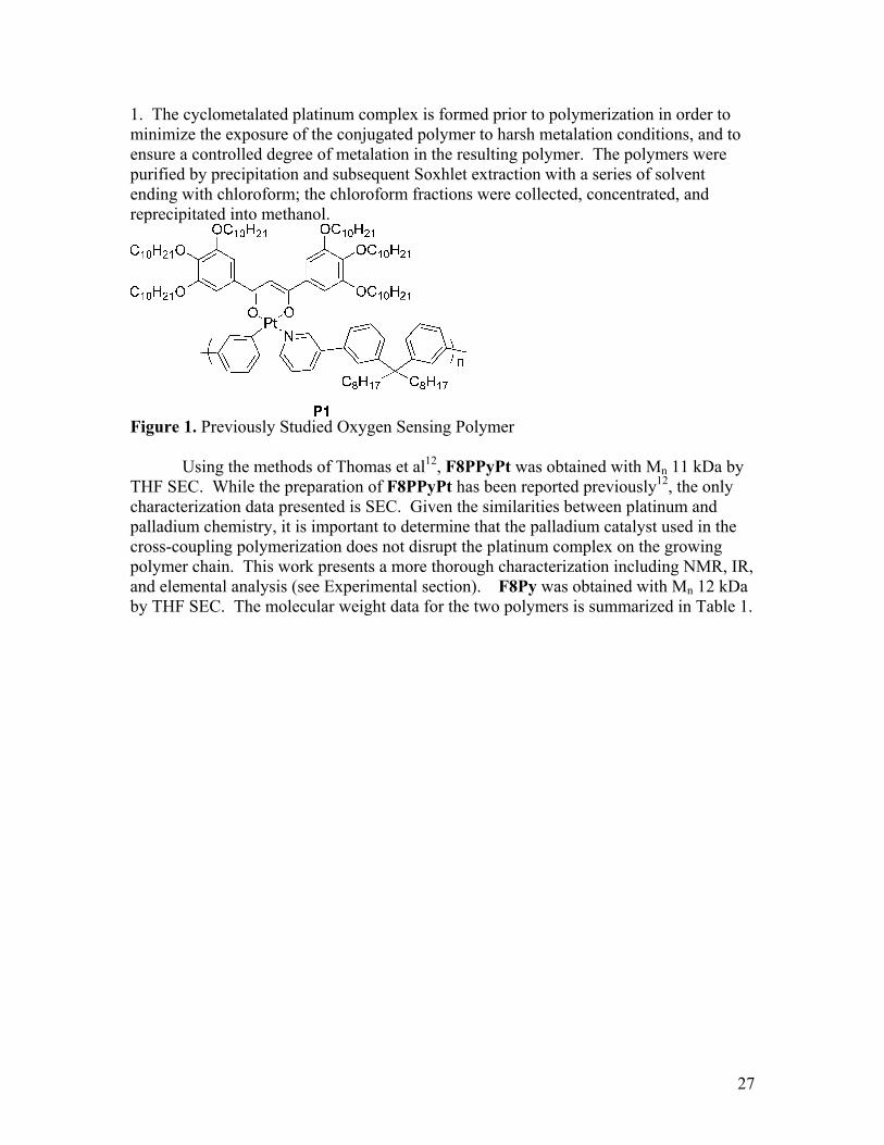
1. The cyclometalated platinum complex is formed prior to polymerization in order to minimize the exposure of the conjugated polymer to harsh metalation conditions, and to ensure a controlled degree of metalation in the resulting polymer. The polymers were purified by precipitation and subsequent Soxhlet extraction with a series of solvent ending with chloroform; the chloroform fractions were collected, concentrated, and reprecipitated into methanol.
Figure 1. Previously Studied Oxygen Sensing Polymer Using the methods of Thomas et al12, F8PPyPt was obtained with Mn 11 kDa by THF SEC. While the preparation of F8PPyPt has been reported previously12, the only characterization data presented is SEC. Given the similarities between platinum and palladium chemistry, it is important to determine that the palladium catalyst used in the cross-coupling polymerization does not disrupt the platinum complex on the growing polymer chain. This work presents a more thorough characterization including NMR, IR, and elemental analysis (see Experimental section). F8Py was obtained with Mn 12 kDa by THF SEC. The molecular weight data for the two polymers is summarized in Table 1.
27
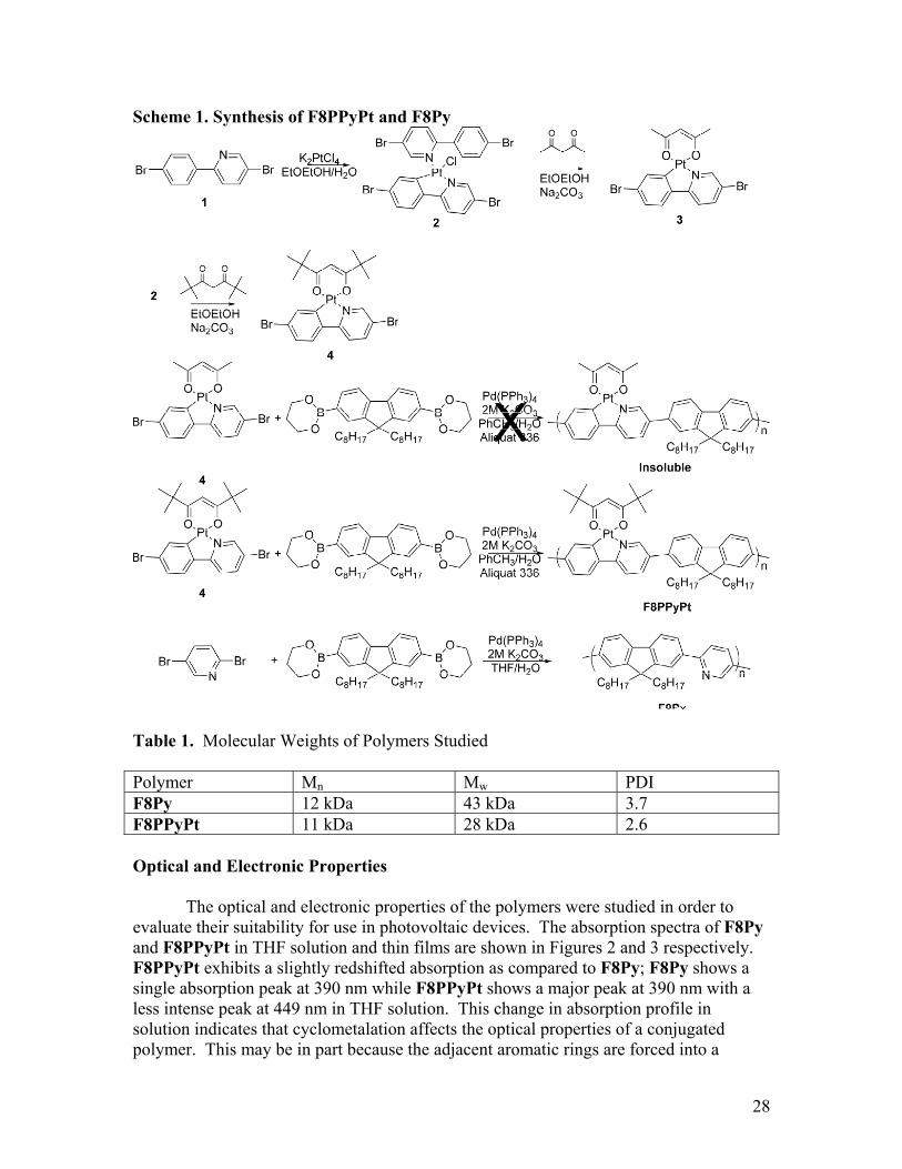
Scheme 1. Synthesis of F8PPyPt and F8Py
Table 1. Molecular Weights of Polymers Studied Polymer Mn Mw PDI F8Py 12 kDa 43 kDa 3.7 F8PPyPt 11 kDa 28 kDa 2.6 Optical and Electronic Properties The optical and electronic properties of the polymers were studied in order to evaluate their suitability for use in photovoltaic devices. The absorption spectra of F8Py and F8PPyPt in THF solution and thin films are shown in Figures 2 and 3 respectively. F8PPyPt exhibits a slightly redshifted absorption as compared to F8Py; F8Py shows a single absorption peak at 390 nm while F8PPyPt shows a major peak at 390 nm with a less intense peak at 449 nm in THF solution. This change in absorption profile in solution indicates that cyclometalation affects the optical properties of a conjugated polymer. This may be in part because the adjacent aromatic rings are forced into a
28

coplanar position by connecting through the platinum, but is also likely the result of incorporation of the platinum orbitals. In a thin film, the absorption properties of F8Py do not change significantly; F8PPyPt retains the two absorption peaks, but the relative intensity of the more redshifted peak increases such that the two peaks have nearly equal intensity. This change in relative peak intensity may indicate that the adjacent repeat units of F8PPyPt are more freely rotating in solution, thus limiting the conjugation unit. In the solid state however, these units do not freely rotate, thus increasing the degree to which longer wavelength transitions are allowed. The optical band gaps of F8Py (2.9 eV) and F8PPyPt (2.6 eV) are larger than ideal for optimal overlap with the AM 1.5 solar spectrum, but the materials still absorb sufficiently in the visible portion of the spectrum to indicate demonstrate the capacity of metalated polymers to provide an increase in exciton diffusion length. The HOMO and the LUMO of the polymers were also measured by cyclic voltammetry in order to determine their potential suitability for use in photovoltaic devices. The HOMO of F8Py was found to be -6.0 eV, while the HOMO of F8PPyPt was found to be -6.1 eV. The similarity in energy levels indicates that the presence of the metal has a minimal impact on the oxidation potential of these polymers. A reduction is not observed for F8Py, but the estimated LUMO based on the optical bandgap is -3.1 eV; the LUMO of F8PPyPt is -3.3 eV. The differences between the LUMO values are slightly larger than the differences between the HOMO values, but the LUMO values are still close to one another. This indicates that the fluorene and pyridine units, which are common to both structures, dominate the electronic properties of these polymers. These results are summarized in Table 2.
Figure 2. Overlaid absorption of F8Py (black) and F8PPyPt (red) in THF solution.
29

Figure 3. Overlaid absorption of F8Py (black) and F8PPyPt (red) in thin films. Table 2. Optical & Electronic Properties of Polymers Sample λmax, CHCl3
solution λonset, film Eg optical
(eV) Eg electronic (eV)
HOMO (eV)
LUMO (eV)
F8Py 390 nm 428 nm 2.9 eV N/A -6.0 -3.1b
F8PPyPt 390 nm, 449 nm
477 nm 2.6 eV 2.8 eV -6.1 -3.3a
aDetermined by onset of reduction bEstimated according to LUMO=HOMO-Eg optical
Photovoltaic Devices The photovoltaic performance of the polymers F8PPyPt and F8Py were evaluated in bilayer TiO2 devices according to the device architecture shown in Figure 4. Figure 5 shows the I-V curves for devices under AM 1.5 illumination. For F8Py, the Voc is 0.31, the Jsc is 0.37 μA cm-2, and the fill factor is 0.28, giving a final efficiency of 3 x 10⁻⁷%. For the platinated polymer F8PPyPt, the Voc is 0.39, the Jsc is 1.63 μA cm-2, and the fill factor is 0.27, giving an overall efficiency of 1.7 x 10⁻⁶%. These results are summarized in Table 3. The fill factor and Voc of the devices remain similar between F8Py and its platinum-containing analog. The major difference between the devices is the Jsc. The Jsc of the F8PPyPt device is roughly four times higher than that of the F8Py device. This large increase in photocurrent can only partly be explained by the redshift in absorption from F8Py to F8PPyPt. Based purely on the improved spectral overlap of F8PPyPt relative to F8Py, F8PPyPt is expected to have a Jsc 2.36 times larger than F8Py. However, the Jsc from the F8PPyPt device is actually 4.4 times larger than that from the F8Py device. These values indicate that F8PPyPt has an intrinsically superior ability to produce photocurrent. This result supports the hypothesis that increasing exciton lifetime by using metalated polymers can lead to increased photocurrent in a bilayer device.
30
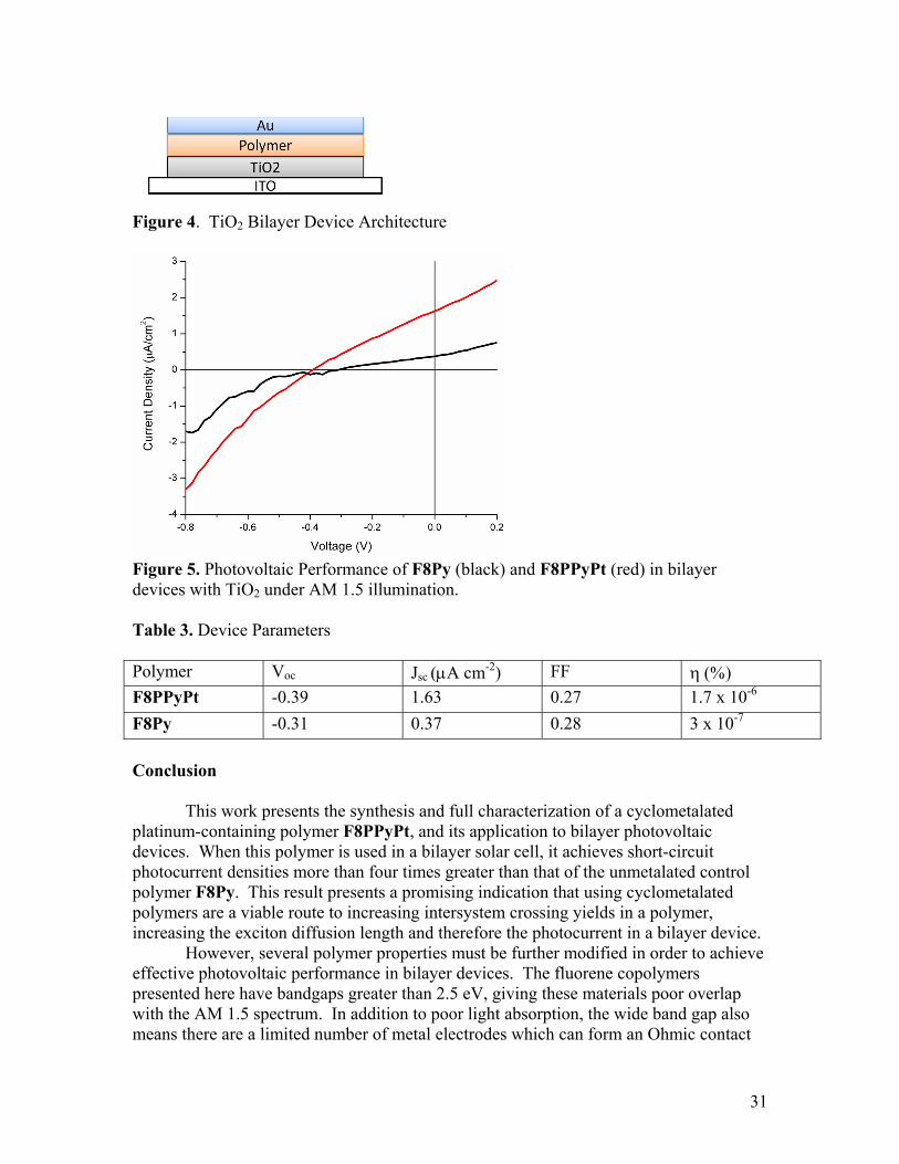
Figure 4. TiO2 Bilayer Device Architecture
Figure 5. Photovoltaic Performance of F8Py (black) and F8PPyPt (red) in bilayer devices with TiO2 under AM 1.5 illumination. Table 3. Device Parameters Polymer Voc Jsc (μA cm-2) FF η (%) F8PPyPt -0.39 1.63 0.27 1.7 x 10⁻⁶ F8Py -0.31 0.37 0.28 3 x 10⁻⁷ Conclusion This work presents the synthesis and full characterization of a cyclometalated platinum-containing polymer F8PPyPt, and its application to bilayer photovoltaic devices. When this polymer is used in a bilayer solar cell, it achieves short-circuit photocurrent densities more than four times greater than that of the unmetalated control polymer F8Py. This result presents a promising indication that using cyclometalated polymers are a viable route to increasing intersystem crossing yields in a polymer, increasing the exciton diffusion length and therefore the photocurrent in a bilayer device. However, several polymer properties must be further modified in order to achieve effective photovoltaic performance in bilayer devices. The fluorene copolymers presented here have bandgaps greater than 2.5 eV, giving these materials poor overlap with the AM 1.5 spectrum. In addition to poor light absorption, the wide band gap also means there are a limited number of metal electrodes which can form an Ohmic contact
31

with the HOMO of these polymers, making efficient charge extraction difficult. A more desirable material for photovoltaics will have a significantly lower band gap in order to harvest the large quantities of photons in the visible region of the spectrum. Additionally, design of new metalated materials for photovoltaic applications requires HOMO and LUMO levels suitable to split excitons into free charge carriers with a common acceptor such as fullerene, and to form an Ohmic contact with ITO/PEDOT:PSS, a commonly used transparent electrode. Further research in this area will focus on the development of new materials designed to incorporate large quantities of a cyclometalated platinum complex, while modifying the optoelectronic properties of the material towards more optimal electronic properties for photovoltaic devices. Experimental Synthesis
1,4′-Dibromo-2-phenylpyridine was synthesized according to published procedures.14 Polymers F8PPyPt was synthesized as previously reported, with additional characterization data given below.12
Platinum(II) (1,4′-dibromo-2-phenylpyridinato-N,C2′) (2,4-
pentanedionato-O,O) (3): In a round bottom flask, 1,4′-dibromo-2-phenylpyridine (2 eq, 2.5 mmol, 0.783 g) was dissolved in 75 mL 2-ethoxyethanol. In a separate flask, potassium tetrachloroplatinate (1 eq, 1.25 mmol, 0.514 g) was dissolved in 25 mL water. The solutions were combined and heated to 90oC overnight. The reaction was then cooled to room temperature and poured over water. The precipitate was collected and washed extensively with methanol and ethanol to obtain a dark green solid that was used in subsequent reactions without purification. This solid (1 eq, 0.793 mmol, 0.678 g) was dissolved in 6 mL 2-ethoxyethanol. To this solution was added sodium carbonate (8 eq, 6.25 mmol, 0.688 g) and acetylacetonate (2.4 eq, 1.875 mmol, 0.188 g). The solution was heated to 100 oC overnight. The next day, the reaction was cooled to room temperature, and water was added. The product was extracted into dichloromethane, the organic layers combined, dried with MgSO4, filtered, and the solvent removed under reduced pressure. The remaining residue was purified by column chromatography (1:2 hexanes:dichloromethane/silica) to yield the desired product as a pale yellow solid with m.p. 303-305oC in 21% yield. 1H NMR (400 MHz, CDCl3) δ 8.99 (d, 1H), 7.90 (dd, 1H), 7.57 (d, 1H), 7.34 (d, 1H), 7.8 (m, 2H), 5.47 (s, 1H), 2.03 (d, 6H). 13C NMR (100 MHz, CDCl3) δ 148.14, 142.48, 141.85, 140.89, 132.83, 126.60, 124.51, 124.46, 119.28, 116.21, 102.82, 28.40, 27.24. HRMS (FAB) for C22H25NO2Br2Pt calcd. 688.9933 found 688.9922. CHN Calcd. 31.70% C, 2.16% H, 2.31% N. Found 31.99% C, 2.16% H, 2.30% N. IR (NaCl film) 2361, 2340, 1653, 1554, 1514, 1423, 1383, 1361, 1294, 1273, 1258, 1224, 886, 867, 840, 809, 749, 725 cm-1.
Platinum(II) (1,4′-dibromo-2-phenylpyridinato-N,C2′) (2,2,6,6-tetramethyl-3,5-heptanedionato-O,O) (3): In a round bottom flask, 1,4′-dibromo-2-phenylpyridine (2 eq, 2.5 mmol, 0.783 g) was dissolved in 75 mL 2-ethoxyethanol. In a separate flask, potassium tetrachloroplatinate (1 eq, 1.25 mmol, 0.514 g) was dissolved in 25 mL water.
32

The solutions were combined and heated to 90oC overnight. The reaction was then cooled to room temperature and poured over water. The precipitate was collected and washed extensively with methanol and ethanol to obtain a dark green solid that was used in subsequent reactions without purification. The solid from this reaction (1 eq, 0.9 mmol, 1.0 g) was dissolved in 90 mL 2-ethoxyethanol; silver oxide (1.5 eq, 1.4 mmol, 0.321 g) and dipivaloylmethane (2 eq, 1.8 mmol, 0.39 mL) were added and the reaction heated to 90oC overnight. The following day the reaction was cooled to room temperature and filtered to remove silver salts. The solids were washed extensively with dichloromethane, and the dichloromethane washed with water to remove 2-ethoxyethanol from the organic layer. The dichloromethane was dried with MgSO4, filtered, and the solvent removed under reduced pressure. The residue from the reaction was then purified by column chromatography (1:1 dichloromethane:hexanes/silica) to yield 0.478 g of the product as a yellow solid (38% yield) with m.p. 200-203oC. 1H NMR (400 MHz, CDCl3) δ 9.10 (d, 1H), 7.91 (dd, 1H), 7.73 (t, 1H), 7.42 (d, 1H), 7.24 (s, 2H), 5.84 (s, 1H), 1.29 (d, 18H). 13C NMR (100 MHz, CDCl3) δ 195.64, 194.21, 166.30, 148.26, 142.76, 142.55, 140.82, 133.62, 126.65, 124.63, 124.58, 119.39, 116.26, 93.69, 41.58, 41.16, 28.80, 28.48. HRMS (FAB) for C16H13NO2Br2Pt calcd. 602.8940 found 602.8948. CHN Calcd. 38.28% C, 3.65% H, 2.03% N. Found 38.51% C, 3.54% H, 2.09% N. IR (NaCl film) 3052, 2969, 2631, 2905, 2867, 2685, 2410, 2305, 1598, 1552, 1529, 1498, 1477, 1416, 1396, 1361, 1261, 1224, 1185, 1142, 1107, 1064, 1013, 878, 794, 744, 726, 702, 664, 626 cm-1.
F8PPyPt: In a round-bottom flask, Pt (1 eq, 0.17 mmol, 0.117 g) and 9,9-Dioctylfluorene-2,7-diboronic acid bis(1,3-propanediol) ester (1 eq, 0.17 mmol, 0.095 g) were dissolved in 5 mL toluene. Then, 5 mL of a 2M potassium carbonate solution in water was added, along with 3 drops Aliquat 336. The solution was degassed by purging with nitrogen for 20 minutes, then Pd(PPh3)4 (0.09 eq, 0.02 mmol, 0.02 g) was added in one portion under strong flow of nitrogen. The solution was heated to 80oC for three days, cooled to room temperature, and then extracted into chloroform. The solvent was removed and the crude polymer dissolved in a minimal volume of chloroform, then precipitated into methanol. The precipitate was collected, and the polymer further purified by sequential Soxhlet extraction with methanol, hexanes, dichloromethane, and chloroform. The dichloromethane fraction was concentrated and reprecipitated to yield 32 mg of polymer (21% yield). 1H NMR (500 MHz, CDCl3) δ 8.2 (m, 3H), 7.4-8.0 (m, 9H), 5.7 (s, 1H), 3.5 (br, 4H), 2.1 (br, 4H), 1.6 (s, 20H), 1.0-1.4 (m, 18H), 0.8 (m, 6H). CHN Calcd. 66.6% C, 7.13% H, 1.52% N. Found 63.57% C, 7.22% H, 1.39% N. SEC (THF) Mn 11 kDa, Mw 28 kDa, PDI 2.6. IR (NaCl film) 3361, 2957, 2923, 2852, 2402, 1659, 1586, 1547, 1530, 1496, 1463, 1435, 1402, 1260, 1095, 1019, 877, 800, 693 cm-1.
F8Py: In a round bottom flask, 9,9-Dioctylfluorene-2,7-diboronic acid bis(1,3-
propanediol) ester (1 eq, 2 mmol, 1.12 g) and 2, 5-dibromopyridine (1 eq, 2 mmol, 0.473 g) were dissolved in 12.5 mL THF. In a separate container, 0.38 g of potassium carbonate was dissolved in 2 mL water. The solutions were combined, and the solution was degassed for 20 minutes. After degassing, Pd(PPh3)4 (0.03 eq, 0.06 mmol, 0.076g) was added and the reaction mixture heated to 65oC for three days. After heating, the reaction was allowed to cool to room temperature and poured over methanol. The solid
33

was recovered by filtration and washed with water and methanol to remove K2CO3. The product was further purified by sequential Soxhlet extraction with methanol, hexanes, ethyl acetate, and dichloromethane. The product was precipitated into methanol to yield a 0.802 g of a yellow-green solid (86% yield). 1H NMR (500 MHz, CDCl3) δ 9.09 (s, 1H), 8.10 (m, 3H), 7.90 (m, 3H), 7.68 (m, 2H), 2.12 (m, 4H), 1.10 (m, 20H), 0.80 (m, 10H). CHN Calcd. 87.31% C, 9.70% H, 2.99% N. Found 86.11% C, 9.45% H, 3.03% N. SEC (THF) Mn 12 kDa, Mw 43 kDa, PDI 3.7. IR (NaCl film) 2960, 2926, 2854, 1589, 1556, 1495, 1457, 1376, 1261, 1227, 1092, 1020, 800 cm-1. Optical and Electrochemical Measurements
Cyclic voltammetry (CV) was performed using a Solartron 1285 potentiostat on thin films dip-coated onto a Pt wire working electrode and submerged in CH3CN freshly distilled from CaH2, using a silver wire pseudo-reference electrode, a platinum auxiliary electrode, and were referenced to the ferrocene/ferrocenium couple, which was taken to be -5.1 eV relative to vacuum.15 Tetrabutylammonium tetrafluoroborate (NBu4BF4) was the supporting electrolyte for all measurements. UV-Visible absorption spectra were obtained using a Cary 50 UV-Visible spectrophotometer. For thin film measurements polymers were spin coated onto untreated glass slides from chloroform solution (10 mg mL-1). A model P6700 Spincoater was used to spin coat the films at 1500 rpm for 60 s. Device Fabrication
Photovoltaic devices were fabricated in a bilayer architecture as follows: ITO/TiO2/Polymer/Al. Indium-doped tin oxide (ITO) coated glass substrates were purchased from Thin Film Devices, Inc. The substrates (150 nm sputtered pattern, 10 Ω -1) were cleaned by 20 minutes of sonication in acetone, 2 percent Helmanex soap in water, and finally isopropanol. The substrates were dried under a stream of air, and a 100 nm thick solid TiO2 film was processed on top using a sol-gel method.16 All subsequent device fabrication was performed inside a glove box under inert Ar atmosphere with water and oxygen levels below 1 ppm. Each polymer was dissolved at a concentration of 16 mg mL-1 in chlorobenzene and spun-coat onto the TiO2 at 1200 rpm for 30 seconds. 100 nm aluminum electrodes were deposited by thermal resistance evaporation at pressures of approximately 10-6 torr to complete the device structure. The shadow mask used during thermal deposition yielded eight independent devices per substrate each with a surface area of 0.03 cm2. Completed devices were then tested under Ar(g) using a 300 W Thermo-Oriel Xenon arc-lamp with flux control spectrally corrected to AM 1.5 G with one filter (Thermo-Oriel #81088). The AM 1.5 G light was further attenuated using a 0.5 O.D. neutral density filter, and the intensity of the AM 1.5 G light was calibrated to be 100 mW cm-2 by a spectrally-matched Hamamatsu S1787-04 photodiode (calibrated by NREL and obtained through Nanosys Inc.). I-V behavior was measured using a computer-controlled Keithley 236 SMU.
34

35
References 1. Markov, D. E.; Tanase, C.; Blom, P. W. M.; Wildeman, J., Phys. Rev. B. 2005, 72,
045217. 2. Shaw, P. E.; Ruseckas, A.; Samuel, I. D. W., Adv. Mater. 2008, 20, 3516-3520. 3. S. E. Shaheen, C. J. B., N. S. Sariciftci, F. Padinger, T.; Fromherz, J. C. H., Appl.
Phys. Lett. 2001, 78, 841-843. 4. Gadisa, A.; Oosterbaan, W. D.; Vandewal, K.; Bolsée, J.-C.; Bertho, S.; D'Haen,
J.; Lutsen, L.; Vanderzande, D.; Manca, J. V., Adv. Funct. Mater. 2009, 19, 3300-3306.
5. Brooks, J.; Babayan, Y.; Lamansky, S.; Djurovich, P. I.; Tsyba, I.; Bau, R.; Thompson, M. E., Inorg. Chem. 2002, 41, 3055-3066.
6. Lamansky, S.; Djurovich, P.; Murphy, D.; Abdel-Razzaq, F.; Kwong, R.; Tsyba, I.; Bortz, M.; Mui, B.; Bau, R.; Thompson, M. E., Inorg. Chem. 2001, 40, 1704-1711.
7. Terao, Y.; Sasabe, H.; Adachi, C., Appl. Phys. Lett. 2007, 90, 103515. 8. Kroeze, J. E.; Savenije, T. J.; Warman, J. M., Adv. Mater. 2002, 14, 1760-1763. 9. Markov, D. E.; Amsterdam, E.; Blom, P. W. M.; Sieval, A. B.; Hummelen, J. C.,
J. Phys. Chem. A. 2005, 109, 5266-5274. 10. Schlebusch, C.; Kessler, B.; Cramm, S.; Eberhardt, W., Synth. Met. 1996, 77,
151-154. 11. Scully, S. R.; Armstrong, P. B.; Edder, C.; Fréchet, J. M. J.; McGehee, M. D., Adv.
Mater. 2007, 19, 2961-2966. 12. Thomas, S. W.; Yagi, S.; Swager, T. M., J. Mater. Chem. 2005, 15, 2829-2835. 13. Murphy, A. R.; Frechet, J. M. J.; Chang, P.; Lee, J.; Subramanian, V., J. Am.
Chem. Soc. 2004, 126, 1596-1597. 14. Venkatesan, K.; Kouwer, P. H. J.; Yagi, S.; Muller, P.; Swager, T. M., J. Mater.
Chem. 2008, 18, 400-407. 15. Pavlishchuk, V. V.; Addison, A. W., Inorg. Chim. Acta 2000, 298, 97-102. 16. Arango, A. C.; Johnson, L. R.; Bliznyuk, V. N.; Schlesinger, Z.; Carter, S. A.;
Hörhold, H.-H., Adv. Mater. 2000, 12, 1689-1692.

Chapter 4: Cyclometalated Platinum Polymers for Bulk Heterojunction Devices: Synthesis, Photophysical Properties and Photovoltaic Performance. Abstract The synthesis and characterization of platinum-containing conjugated polymers in which the platinum atom is attached to the conjugated backbone via a 2-thienylthiazole C^N ligand is presented. The newly designed platinum-containing monomer can be polymerized under both Stille and Suzuki conditions. The polymers exhibit optical bandgaps between 2.4 and 1.65 eV depending on the presence or absence of metal, and the choice of comonomer. Formation of triplet excitons is detected indirectly by measuring photosensitized emission of singlet oxygen in both solution and in film. The ability of the materials to sensitize formation of singlet oxygen varies both with excitation wavelength and with the change from solution to solid state. This study indicates design principles for developing conjugated polymers with significant triplet yields in the solid state. The photovoltaic performance of these polymers was also evaluated in preliminary experiments, giving power conversion efficiencies approaching 1.5% for a bulk heterojunction cell with PC70BM. Introduction
Conjugated polymers have highly tunable optoelectronic properties combined with ease of processing1, 2 making them attractive materials in the challenging search for efficient low-cost photovoltaic devices. Recently, there has been significant interest in conjugated organometallic polymers as donor polymers for use in bulk heterojunction (BHJ) solar cells in combination with fullerene acceptors.3-10 In particular, polyplatinynes have drawn some attention as a result of their absorption profiles extending as far as the near infrared10, and their promising charge transport properties with reported hole mobilities as high as 1.0 × 10⁻² cm2 V-1 s-1 in field-effect transistors (FETs). 9 In addition, polyplatinynes have demonstrated formation of triplet excitons3,
7. Materials with large triplet yields may well provide access to increased photocurrent in
organic photovoltaic devices.11 Triplet excited state lifetimes are typically in the microsecond regime, which is three orders of magnitude longer than the nanosecond decays typically observed for singlet excited states in conjugated polymers. Given that exciton diffusion length (LD) is determined by exciton lifetime (τ) and exciton diffusivity (D) according to the equation
DLD τ= , a significant increase in lifetime is expected to lead to a longer exciton diffusion length, which would be advantageous for bilayer photovoltaic devices. Triplet-forming polymers have been reported to inhibit geminate pair recombination3 and to increase the exciton diffusion length12 in bulk heterojunction devices. However, the conjugated organometallic polymers that have been shown to form triplets in the solid state are also large bandgap systems12 (>2.5 eV), and therefore power conversion efficiencies are limited by the poor overlap of their absorption spectrum with the solar irradiance. While lower band gap systems have demonstrated formation of triplet excitons in solution, this result does not necessarily translate to the solid state. Furthermore, performance of these lower band gap polymers are limited by charge mobility.7 It is also important to consider that formation of triplet excitons in a bulk heterojunction device is anticipated to improve the photocurrent primarily by decreasing geminate recombination, as charge separation in a well-mixed bulk heterojunction occurs on the femtosecond time scale13
36
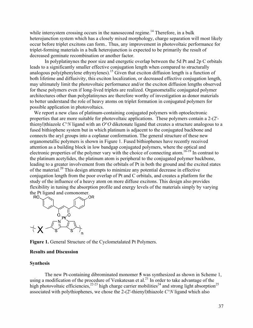
while intersystem crossing occurs in the nanosecond regime.14 Therefore, in a bulk heterojunction system which has a closely mixed morphology, charge separation will most likely occur before triplet excitons can form.. Thus, any improvement in photovoltaic performance for triplet-forming materials in a bulk heterojunction is expected to be primarily the result of decreased geminate recombination or another factor.
In polyplatinynes the poor size and energetic overlap between the 5d Pt and 2p C orbitals leads to a significantly smaller effective conjugation length when compared to structurally analogous poly(phenylene ethynylenes).15 Given that exciton diffusion length is a function of both lifetime and diffusivity, this exciton localization, or decreased effective conjugation length, may ultimately limit the photovoltaic performance and/or the exciton diffusion lengths observed for these polymers even if long-lived triplets are realized. Organometallic conjugated polymer architectures other than polyplatinynes are therefore worthy of investigation as donor materials to better understand the role of heavy atoms on triplet formation in conjugated polymers for possible application in photovoltaics.
We report a new class of platinum-containing conjugated polymers with optoelectronic properties that are more suitable for photovoltaic applications. These polymers contain a 2-(2'-thienyl)thiazole C^N ligand with an O^O diketonate ligand that creates a structure analogous to a fused bithiophene system but in which platinum is adjacent to the conjugated backbone and connects the aryl groups into a coplanar conformation. The general structure of these new organometallic polymers is shown in Figure 1. Fused bithiophenes have recently received attention as a building block in low bandgap conjugated polymers, where the optical and electronic properties of the polymer vary with the choice of connecting atom.16-19 In contrast to the platinum acetylides, the platinum atom is peripheral to the conjugated polymer backbone, leading to a greater involvement from the orbitals of Pt in both the ground and the excited states of the material.20 This design attempts to minimize any potential decrease in effective conjugation length from the poor overlap of Pt and C orbitals, and creates a platform for the study of the influence of a heavy atom on more diffuse excitons. This design also provides flexibility in tuning the absorption profile and energy levels of the materials simply by varying the Pt ligand and comonomer.
Figure 1. General Structure of the Cyclometalated Pt Polymers.
Results and Discussion
Synthesis
The new Pt-containing dibrominated monomer 5 was synthesized as shown in Scheme 1, using a modification of the procedure of Venkatesan et al.21 In order to take advantage of the high photovoltaic efficiencies,22-23 high charge carrier mobilities24 and strong light absorption25 associated with polythiophenes, we chose the 2-(2'-thienyl)thiazole C^N ligand which also
37

contains a thiophene. The thiazole unit should also contribute favorably to charge mobility,26,27 while providing a nitrogen atom for Pt coordination and minimizing donor-acceptor interactions in the polymer. The diphenyl ketonate ligand provides solubility via the peripheral dialkoxy groups. Since platinum complexes containing the 2-(2'-thienyl)thiazole ligand have not been reported previously, model complex 4 without terminal bromine moieties was synthesized to enable a comparison of optical and electronic properties of the repeat unit to those of the corresponding polymers. Stille and Suzuki polymerizations of the metal complex were carried out using Pd(PtBu3)2 and conditions were based on those developed by the Fu group28, 29, as shown in Scheme 2. The unmetalated ligand 2 was copolymerized with 9, 9-dioctylfluorene under conventional Suzuki conditions to yield a high molecular weight polymer, allowing for a comparison of metalated and unmetalated versions of the polymer. Synthesis of an unmetalated analog is not possible with the thiophene copolymers, as for those materials all of the solubilizing units are based on the metal complex. The Pd(PtBu3)2 palladium system was used in place of the Pd(PPh3)4 analog for the metal-containing polymers because compound 5 was found to degrade under polymerization conditions using the more classical catalyst. This degradation was confirmed by significant changes to the 1H NMR spectrum of 5 after adding a solution of PPh3. The exact nature of this degradation is unknown, but Pt(acac)2 complexes have been shown to react with triaryl phosphine ligands by displacing one of the O atoms of the diketonate ligand30 or by forming a pentacoordinate complex31. The tri(tert-butyl)phosphine ligand is significantly more bulky than triphenylphosphine, as evidenced by its ability to form a stable divalent Pd(0) complex at room temperature29, and by its larger cone angle of 182o versus the 145o determined for triphenylphosphine32. This bulkiness likely hinders coordination of the ligand on the Pt center of 5, allowing the polymerization to proceed without disturbance to the metal complex. In addition, the high activity of the Pd(PtBu3)2 catalyst system makes it possible to achieve high molecular weight polymers via both Stille and Suzuki coupling routes at 40 oC, a lower reaction temperature than the 80 - 100 oC frequently used for analogous Pd-catalyzed polymerizations. The reduced reaction temperature should also contribute to the improved stability of the platinum complex during polymerization.
38

Scheme 1. Synthesis of Monomer and Model Complex
39
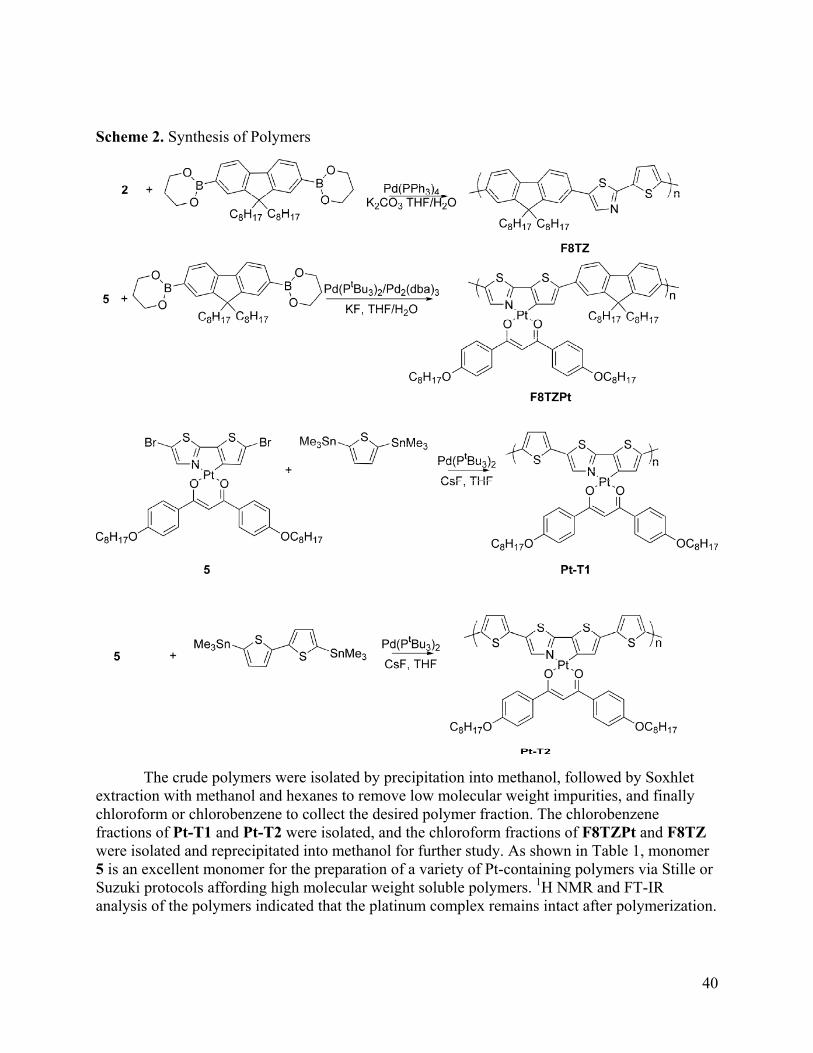
Scheme 2. Synthesis of Polymers
The crude polymers were isolated by precipitation into methanol, followed by Soxhlet extraction with methanol and hexanes to remove low molecular weight impurities, and finally chloroform or chlorobenzene to collect the desired polymer fraction. The chlorobenzene fractions of Pt-T1 and Pt-T2 were isolated, and the chloroform fractions of F8TZPt and F8TZ were isolated and reprecipitated into methanol for further study. As shown in Table 1, monomer 5 is an excellent monomer for the preparation of a variety of Pt-containing polymers via Stille or Suzuki protocols affording high molecular weight soluble polymers. 1H NMR and FT-IR analysis of the polymers indicated that the platinum complex remains intact after polymerization.
40

Table 1. Molecular Weights of Polymers Studied Polymer Mn Mw PDI F8TZb 17 kDa 32 kDa 1.8 F8TZPtb 24 kDa 47 kDa 1.9 Pt-T1a 45 kDa 84 kDa 1.9 Pt-T2b 22 kDa 41 kDa 1.9
a SEC in Dichlorobenzene, b SEC in THF (both calibrated with polystyrene standards)
Optical and Electronic Properties
The optical and electronic properties of 4 and all of the polymers were studied in order to determine the suitability of these materials for photovoltaic applications, and to further understand the effects of extending conjugation through a cyclometalated platinum complex. Figure 2a shows the UV-Vis absorbance spectra for 4 and the polymers in dilute chloroform solution and Figure 2b shows the UV-Vis absorbance spectra for 4 and the polymers in thin films. All of the metallated polymers exhibit a strong transition at approximately 350 nm, which, given the similarity between this peak and the absorption profile of the small molecule 4, is attributed to the direct excitation of the metal complex. The polymers also show strong transitions at longer wavelengths, with peaks at 598 nm (Pt-T2) 610 nm (Pt-T1) and 520 nm (F8TZPt) for solution spectra. These peaks are attributed to excitations delocalized along the conjugated polymer chain. Metalation has a significant impact on the absorption spectra of the fluorene copolymers; F8TZ exhibits a single absorption peak at 449 nm, while F8TZPt exhibits one higher energy absorption associated with the platinum complex as well as a lower energy absorption associated with more delocalized excitations. This redshift is most likely due in part to the enforced planarity of the 2-(2'-thienyl)thiazole unit when complexed to the platinum atom, but also due to orbital interactions with the platinum atom. The absorption for F8TZPt is also significantly redshifted when compared to those of the previously reported platinated polyfluorenes P-1 and P-2 shown in Figure 3.33
41

Figure 2. Overlaid Absorption Spectra of Polymers and Small Molecule in chloroform solution (a) and thin film (b): 4 (black), F8TZ (purple), F8TZPt (red), Pt-T1 (blue), and Pt-T2 (green).
Figure 3. Previously reported platinum-containing polyfluorenes.33
Changing the C^N ligand in the fluorene copolymers from 2-phenylpyridine in P1 or P2 to 2-(2'-thienyl)thiazole in F8TZPt causes the lower energy absorption maximum to shift from 450 nm33 to 520 nm. The small molecule complexes containing 2-phenylpyridine20 and 2-(2'-thienyl)thiazole have similar absorption spectra, so this larger bathochromic shift suggests that F8TZPt may have significant donor-acceptor character. Further, these results show that the optical properties of these platinum-containing polymers can be tuned by modifying either or both the platinum complex and the comonomer. The UV-Vis spectrum of F8TZ exhibits a redshift in peak absorption going from solution (449 nm) to film (475 nm); F8TZPt also exhibits a redshift from 520 nm to 555 nm when changing from solution to film. This shift in absorption to longer wavelengths together with the enhanced vibronic structure is indicative of increased π−π stacking in the solid state. The thiophene copolymers Pt-T1 and Pt-T2 also exhibit redshifts
in particular, the relative
corresponding to the small molecule is much more intense than that of the delocalized excitation;
in absorption peaks going from solution to the solid state. For Pt-T1intensities of the short and long wavelength peaks change; in solution the absorption peak
42
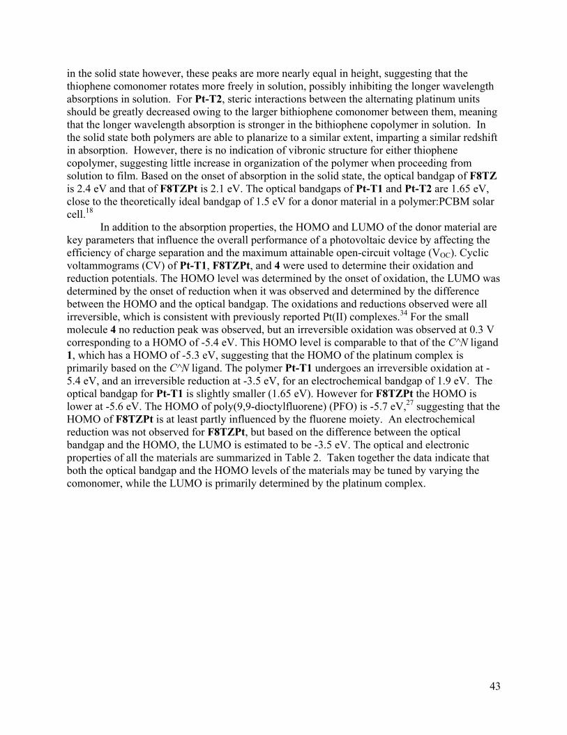
in
g n
ift
al are
clic
as
t 0.3 V gand
andgap for Pt-T1 is slightly smaller (1.65 eV). However for F8TZPt the HOMO is lo er a
the solid state however, these peaks are more nearly equal in height, suggesting that the thiophene comonomer rotates more freely in solution, possibly inhibiting the longer wavelengthabsorptions in solution. For Pt-T2, steric interactions between the alternating platinum units should be greatly decreased owing to the larger bithiophene comonomer between them, meaninthat the longer wavelength absorption is stronger in the bithiophene copolymer in solution. Ithe solid state both polymers are able to planarize to a similar extent, imparting a similar redshin absorption. However, there is no indication of vibronic structure for either thiophene copolymer, suggesting little increase in organization of the polymer when proceeding from solution to film. Based on the onset of absorption in the solid state, the optical bandgap of F8TZ is 2.4 eV and that of F8TZPt is 2.1 eV. The optical bandgaps of Pt-T1 and Pt-T2 are 1.65 eV,close to the theoretically ideal bandgap of 1.5 eV for a donor material in a polymer:PCBM solar cell.18
In addition to the absorption properties, the HOMO and LUMO of the donor materikey parameters that influence the overall performance of a photovoltaic device by affecting the efficiency of charge separation and the maximum attainable open-circuit voltage (VOC). Cyvoltammograms (CV) of Pt-T1, F8TZPt, and 4 were used to determine their oxidation and reduction potentials. The HOMO level was determined by the onset of oxidation, the LUMO wdetermined by the onset of reduction when it was observed and determined by the difference between the HOMO and the optical bandgap. The oxidations and reductions observed were all irreversible, which is consistent with previously reported Pt(II) complexes.34 For the small molecule 4 no reduction peak was observed, but an irreversible oxidation was observed acorresponding to a HOMO of -5.4 eV. This HOMO level is comparable to that of the C^N li1, which has a HOMO of -5.3 eV, suggesting that the HOMO of the platinum complex is primarily based on the C^N ligand. The polymer Pt-T1 undergoes an irreversible oxidation at -5.4 eV, and an irreversible reduction at -3.5 eV, for an electrochemical bandgap of 1.9 eV. The optical b
w t -5.6 eV. The HOMO of poly(9,9-dioctylfluorene) (PFO) is -5.7 eV,27 suggesting that the HOMO of F8TZPt is at least partly influenced by the fluorene moiety. An electrochemical reduction was not observed for F8TZPt, but based on the difference between the optical bandgap and the HOMO, the LUMO is estimated to be -3.5 eV. The optical and electronic properties of all the materials are summarized in Table 2. Taken together the data indicate that both the optical bandgap and the HOMO levels of the materials may be tuned by varying the comonomer, while the LUMO is primarily determined by the platinum complex.
43
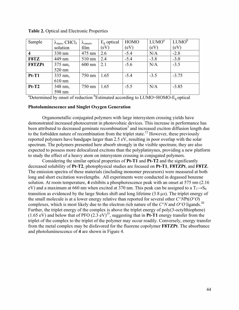
Table 2. Optical and Electronic Properties
aSample λmax, CHCl3 solution
λonset, film
Eg optical (eV)
HOMO (eV)
LUMO (eV)
LUMOb (eV)
4 330 nm 475 nm 2.6 -5.4 N/A -2.8 F8TZ 449 nm 510 nm 2.4 -5.4 -3.8 -3.0 F8TZPt 375 nm,
520 nm 600 nm 2.1 -5.6 N/A -3.5
Pt-T1 335 nm, 610 nm
750 nm 1.65 -5.4 -3.5 -3.75
Pt-T2 348 nm, 598 nm
750 nm 1.65 -5.5 N/A -3.85
aDetermined by onset of reduction bEstimated according to LUMO=HOMO-Eg optical
hotoluminescence and Singlet Oxygen Generation
s with large intersystem crossing yields have emonstrated increased photocurrent in photovoltaic devices. This increase in performance has
ibute te io crea n ength due to the forbidd f re inati m the t tate.12 However, these previously
orted poly ban n 2.5 eV, resulting in poor overlap with the solar m. Th s pre r orb stro n the vi spectru ey are also
to p re delocalized excitons than the polyplatinynes, providing a new platform to study the effect of a heavy atom on intersystem crossing in conjugated polymers.
Considering the simi l rties o 1 and P and the icantly decreased solubility of Pt-T2, photophysical studies are focused on Pt-T1, F8TZPt, and F8TZ.
ission thes l uding er pre s) wer ured at both long and short excitation wavelengths. All experiments were conducted in degassed benzene
nm (2.16 eV) and a maximum at 660 nm when excited at 370 nm. This peak can be assigned to a T1→S0
g lifetime (3.8 μs). The triplet energy of small molecule is a C^N O^O)
comple ds.20
sfer ce
P
Organometallic conjugated polymerdbeen attr d to decreased
en nature o geminacomb
recombinaton fro
n3 and inriplet s
sed excito diffusion l
rep mers have dgaps larger thaspectru e polymer sented he e abs ngly i sible m; thexpected ossess mo
lar optica prope f Pt-T t-T2 signif
The em spectra of e materia s (incl monom cursor e meas
solution. At room temperature, 4 exhibits a phosphorescence peak with an onset at 575
transition as evidenced by the large Stokes shift and lonthe t a lower energy relative than reported for several other Pt(
xes, which is most likely due to the electron rich nature of the C^N and O^O liganFurther, the triplet energy of the complex is above the triplet energy of poly(3-octylthiophene) (1.65 eV) and below that of PFO (2.3 eV)35, suggesting that in Pt-T1 energy transfer from the triplet of the complex to the triplet of the polymer may occur readily. Conversely, energy tranfrom the metal complex may be disfavored for the fluorene copolymer F8TZPt. The absorbanand photoluminescence of 4 are shown in Figure 4.
44
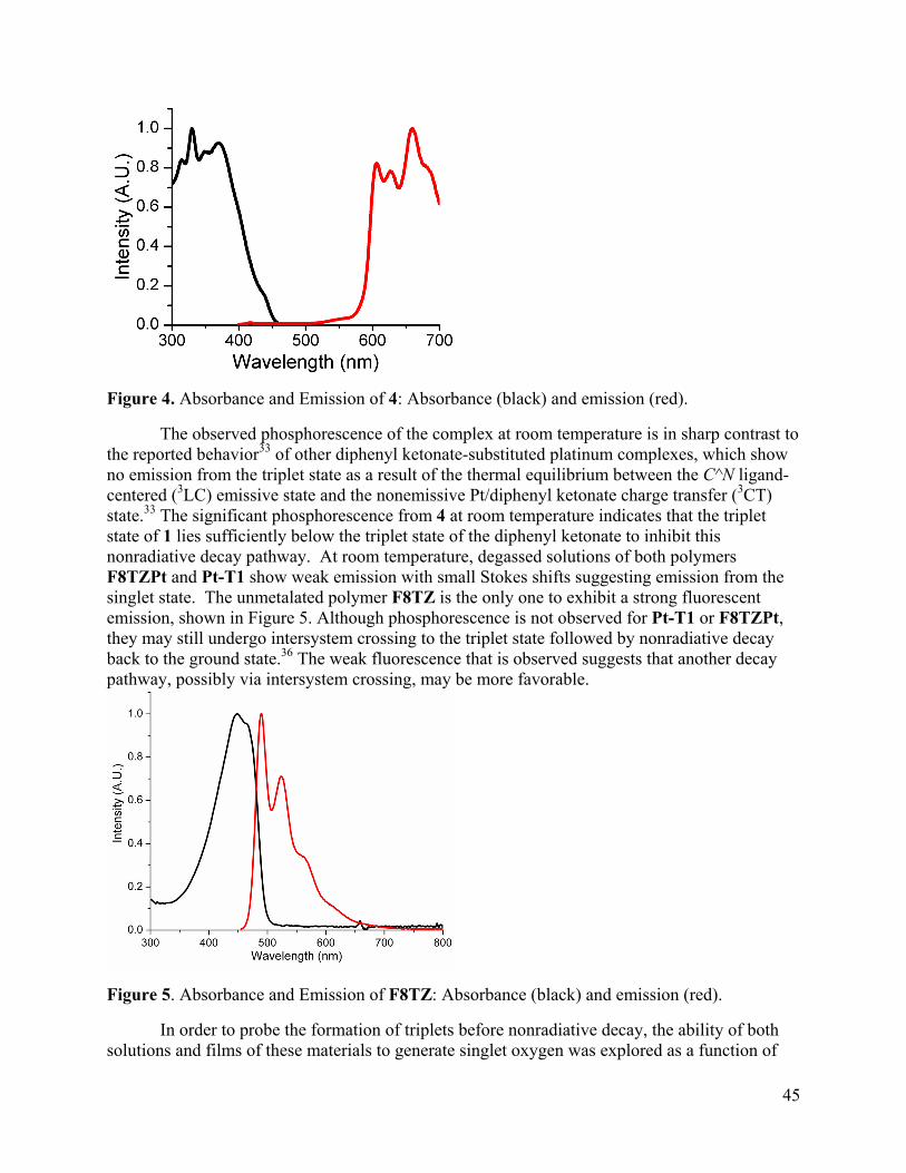
Figure 4. Absorbance and Emission of 4: Absorbance (black) and emission (red).
The observed phosphorescence of the complex at room temperature is in sharp contrast to the reported behavior33 of other diphenyl ketonate-substituted platinum complexes, which show no emission from the triplet state as a result of the thermal equilibrium between the C^N ligand-centered (3LC) emissive state and the nonemissive Pt/diphenyl ketonate charge transfer (3CT) state.33 The significant phosphorescence from 4 temperature indicates that the triplet
his
F8TZP
at roomstate of 1 lies sufficiently below the triplet state of the diphenyl ketonate to inhibit tnonradiative decay pathway. At room temperature, degassed solutions of both polymers
t and Pt-T1 show weak emission with small Stokes shifts suggesting emission from the singlet state. The unmetalated polymer F8TZ is the only one to exhibit a strong fluorescent emission, shown in Figure 5. Although phosphorescence is not observed for Pt-T1 or F8TZPt, they may still undergo intersystem crossing to the triplet state followed by nonradiative decay back to the ground state.36 The weak fluorescence that is observed suggests that another decaypathway, possibly via intersystem crossing, may be more favorable.
Figure 5. Absorbance and Emission of F8TZ: Absorbance (black) and emission (red).
In order to probe the formation of triplets before nonradiative decay, the ability of both solutions and films of these materials to generate singlet oxygen was explored as a function of
45
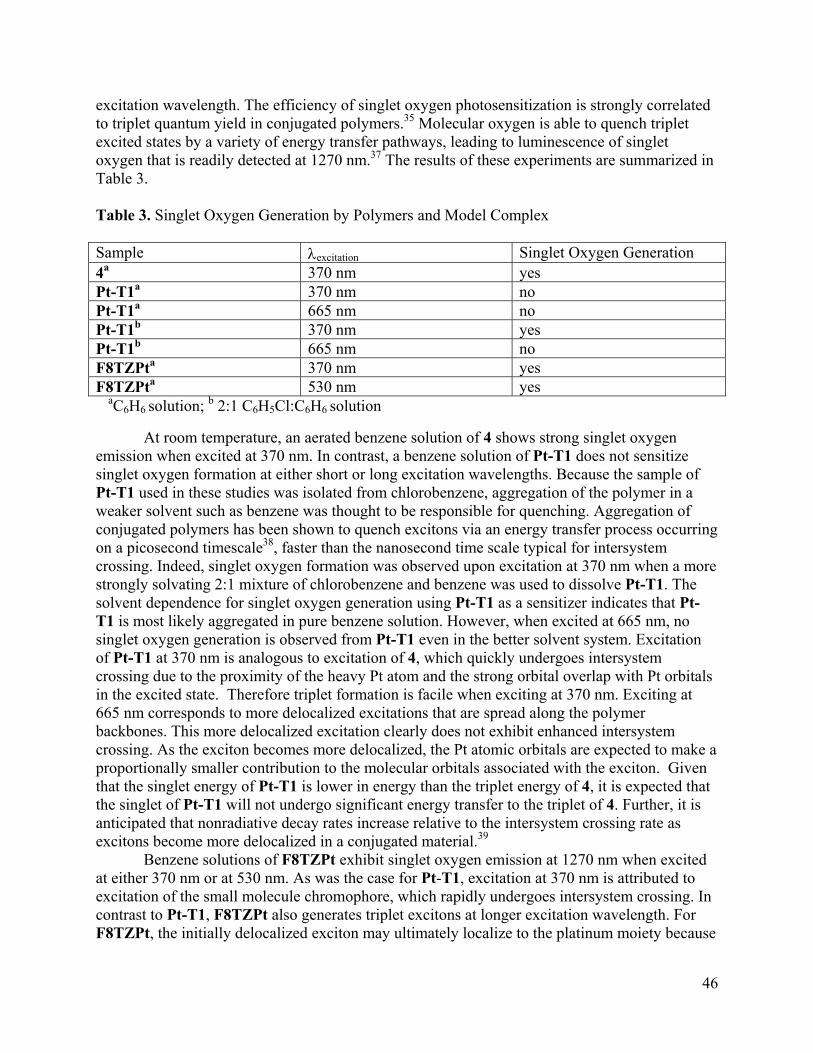
excitation wavelength. The efficiency of singlet oxygen photosensitization is strongly correlated to triplet quantum yield in conjugated polymers.35 Molecular oxygen is able to quench triplet excited states by a variety of energy transfer pathways, leading to luminescence of singlet oxygen that is readily detected at 1270 nm.37 The results of these experiments are summarized in Table 3.
Table 3. Singlet Oxygen Generation by Polymers and Model Complex Sample λexcitation Singlet Oxygen Generation 4a 370 nm yes Pt-T1a 370 nm no Pt-T1a 665 nm no Pt-T1b 370 nm yes Pt-T1b 665 nm no F8TZPta 370 nm yes F8TZPt 530 nm yes a
aC6H6 solution; b 2:1 C6H5Cl:C6H6 solution
At room temperature, an aerated benzene solution of 4 shows strong singlet oxygen emission when excited at 370 nm. In contrast, a benzene solution of Pt-T1 does not sensitize singlet oxygen formation at either short or long excitation wavelengths. Because the sample of Pt-T1 used in these studies was isolated from chlorobenzene, aggregation of the polymer in a weaker solvent such as benzene was thought to be responsible for quenching. Aggregation of conjugated polymers has been shown to quench excitons via an energy transfer process occurring
al for intersystem rossing. Indeed, singlet oxygen formation was observed upon excitation at 370 nm when a more
solvating 2:1 mixture of nzene and benzene wasvent dependence for singlet ox eration using Pt-T1 as a sensitizer indicates that Pt-
ost likely aggregated in pure benzene solution. However, when excited at 665 nm, no xygen generation is obse Pt-T1 even in the better solvent system. Excitation at 370 nm is analogous to excitation of 4, which quickly undergoes intersystem due to the proximity of the heavy Pt atom and the strong orbital overlap with Pt orbitals
ted state. Therefore tr ation is facile when exciting at 370 nm. Exciting at rresponds to more delo xcitations that are spread along the polymer
learly does not exhi hanced intersystem cr lized, the Pt atomic orbitals are expected to make a pr port ven
at
to
se
on a picosecond timescale38, faster than the nanosecond time scale typiccstrongly chlorobe used to dissolve Pt-T1. The sol ygen genT1 is msinglet o rved fromof Pt-T1crossingin the exci iplet form665 nm coba b n
calized exck o es. This more delocalized e citation c
ossing. As the exciton becomes more delocabit en
o ionally smaller contribution to the molecular orbitals associated with the exciton. Githat the singlet energy of Pt-T1 is lower in energy than the triplet energy of 4, it is expected ththe singlet of Pt-T1 will not undergo significant energy transfer to the triplet of 4. Further, it is anticipated that nonradiative decay rates increase relative to the intersystem crossing rate as excitons become more delocalized in a conjugated material.39
Benzene solutions of F8TZPt exhibit singlet oxygen emission at 1270 nm when excited at either 370 nm or at 530 nm. As was the case for Pt-T1, excitation at 370 nm is attributedexcitation of the small molecule chromophore, which rapidly undergoes intersystem crossing. In contrast to Pt-T1, F8TZPt also generates triplet excitons at longer excitation wavelength. For F8TZPt, the initially delocalized exciton may ultimately localize to the platinum moiety becau
46

the platinum repeat unit is lower in energy than poly(9,9-dioctylfluorene)40 as evidenced by threlative energy levels. The singlet energy of F8TZPt is close in energy to the triplet energy of 4suggesting that energy transfer from the singlet of F8TZPt to the triplet of 4 can occur reaThis more localized exciton exhibits strong spin-orbit coupling through the platinum atom, leading to formation of triplet excitons as evidenced by sensitized formation of singlet oxygen.The difference in triplet formation observed between F8TZPt and Pt-T1 at long excitatwavelength is illustrated schematically in Figure 6. Red dashed lines represent the excitons initially formed at long excitation wavelengths, with energy transfer occurring to the monomer unit of 4 in the case of F8TZPt.
eir ,
dily.
ion
47

Figure 6. The different means of promotion and inhibition of triplet formation in F8TZPt and Pt-T1 for long wavelength excitations.
While both polymers are able to sensitize formation of singlet oxygen in solution, neither polymer was observed to sensitize singlet oxygen formation in a thin film. The difference in triplet formation from solution to solid phase, as evidenced by singlet oxygen generation, most likely arises as the result of intermolecular interactions providing a faster decay pathway,
48

analogous to aggregates in solution. For example, regioregular poly(3-alkyl)thiophenes (P3ATs) have a large triplet yield in solution (ΦT=0.77) 35, but do not readily form triplets in a film.41 Formation of triplet states in the solid state is disfavored for P3ATs in part because the formation of more delocalized, lower energy excimers is more favorable.42 Formation of triplet excitons in P3AT films is also partly disfavored as a result of decreased twisting between adjacent thiophene units; an increased twist angle between adjacent thiophenes leads to increased spin-orbit coupling.43 Given that spin-orbit coupling is dominated by the platinum atom in both F8TZPt and Pt-T1, the change in triplet formation from solution to solid state in F8TZPt and Pt-T1 (as evidenced by singlet oxygen generation) should be primarily the result of lower-energy excimers forming in the polymer films and not a decrease in twisting between adjacent thiophene units. Together, these results suggest that polymers with excitons centered on molecular orbitals with significant contribution from a heavy atom and with lowered aggregation in the solid state would be desirable to generate triplet excitons in a film for photovoltaic devices.
Photovoltaic Devices and Charge Mobility The polymers Pt-T1 and F8TZPt were studied in bulk heterojunction photovoltaic devices with PC60BM to better understand the influence of the cyclometalated platinum moiety on performance. The optimal blending ratio for both F8TZPt and Pt-T1 was found to be 1:4 (polymer:PC60BM). Results optimized for polymer:PCBM ratio, thickness, and annealing give power conversion efficiencies of 0.40% for F8TZPt, and 1.29% for Pt-T1 under AM 1.5 illumination at 100 mW cm-1. Figure 7 shows the performance of the devices without annealing. Thermal annealing was found to significantly decrease the performance of the devices, presumably as a result of excessive phase segregation between polymer and PC60BM. For F8TZPt the Jsc is 3.5 mA cm-2, the Voc is 0.38 V, and the fill factor is 0.30. For Pt-T1 the Jsc is 5.3 mA cm-2, the Voc is 0.65 V, and the fill factor is 0.37. The performance of Pt-T1 is significantly better than F8TZPt, which is partly the result of its superior overlap with the solar spectrum. In light of its superior performance, Pt-T1 was also studied in a bulk heterojunction solar cell with PC70BM. PC70BM absorbs significantly further into the visible spectrum as compared to PC60BM, meaning that it can potentially contribute to photocurrent generation. For this system as well the optimal blending ratio is found to be 1:4 Pt-T1:PC70BM. The best performance is found without annealing, giving a power conversion efficiency of 1.46%, as shown in Figure 7. The Jsc is 5.15 mA cm-2, the Voc is 0.69 V, and the fill factor is 0.41. Interestingly, although PC70BM is expected to improve device performance by contributing to photocurrent, the short circuit current density in the Pt-T1:PC70BM devices is lower than in the Pt-T1:PC60BM devices. Instead, the improvement in device performance arises from an increase in the open circuit voltage and fill factor. This result suggests that Pt-T1 may exhibit improved morphology in a blend with PC70BM. Based on the electrochemistry described previously, it is possible that holes localize at the platinum unit of F8TZPt and this localization inhibits charge transport in a device. The HOMO of 4 is higher than the HOMO of F8TZPt, suggesting that the platinum-containing monomer may act as a local energy minimum for holes in the device.
49

Figure 7. Photovoltaic Performance of F8TZPt (red) and Pt-T1 (black) blended with PC60BM; Pt-T1 blended with PC70BM (blue), all under AM 1.5 illumination
In order to better understand potential limiting factors on photovoltaic performance of polymers containing the cyclometalated platinum complex, the space charge limited current (SCLC) mobilities of Pt-T1 and F8TZPt were measured. Unlike FETs, SCLC mobility determines charge mobility in the vertical direction under no gate bias, making it potentially a more relevant measurement of charge mobility in the context of photovoltaic devices. The zero-field hole mobility of F8TZPt is 2.5 x 10⁻⁹ cm2 V s-1. The inefficient charge transport measured for this polymer clearly contributes to its poor photovoltaic performance, and further suggests that the platinum complex may act as a charge and energy trap in this polymer in which the platinum complex is copolymerized with the wider bandgap fluorene unit. In contrast, the zero-field hole mobility of Pt-T1 was measured as 1 x 10⁻⁵ cm-2 V-1 s-1. The SCLC mobilities for the pristine polymers and the bulk heterojunction photovoltaic device parameters are summarized in table 5. The striking difference in SCLC hole mobility between Pt-T1 and F8TZPt demonstrates that comonomer selection may affect both charge transport and photophysics of the resulting polymer. The SCLC hole mobility of Pt-T1 is lower than that of polythiophenes44, 45 (10-4 to 10-3
cm2 V-1 s-1), but higher than the reported SCLC hole mobilities of polyplatinynes7 (10-8 to 10-7 cm2 V-1s-1). The improved SCLC hole mobility observed for Pt-T1 relative to the polyplatinynes shows that platinum-containing conjugated polymers with connectivity via a C^N ligand are an attractive alternative route to organometallic polymers for photovoltaics. Table 5. Device Parameters: F8TZPt:PCBM and Pt-T1:PCBM Blend Photovoltaic Devices and SCLC Hole Mobility Active Layer Voc Jsc FF η μh (SCLC) F8TZPt:PC60BM 0.38 V 3.5 mA cm-2 0.30 0.40% 2.5 x 10⁻⁹
cm2 V-1s-1
Pt-T1:PC60BM 0.65 V 5.3 mA cm-2 0.37 1.29% 1.0 x 10⁻⁵ cm2 V-1s-1 Pt-T1:PC70BM 0.69 5.15 mA cm-2 0.41 1.46% 1.0 x 10⁻⁵ cm2 V-1s-1
50

Conclusions
This work presents a new approach to low bandgap platinum-containing conjugated polymers based on a platinum monomer with C^N and O^O diketonate ligands. In these materials the platinum atom is attached adjacent to the conjugated backbone, and therefore does not inhibit exciton delocalization along the polymer chain, providing a means to study the effect of a heavy atom on diffuse excitons. Photovoltaic devices fabricated from these materials yield efficiencies approaching 1.5%, demonstrating that cyclometalated platinum polymers are an attractive new class of materials for organic photovoltaics. Photophysical studies indicate that for some materials long wavelength excitations experience rapid nonradiative decay leading to no observable triplet exciton formation, while other materials exhibit localization of an initially delocalized exciton. This localization promotes triplet formation but is disadvantageous to charge transport in a photovoltaic device. The results presented here suggest that the development of conjugated materials having both significant triplet yields and overlap with the visible spectrum in the solid state will require new materials designed to minimize nonradiative decay pathways at longer excitation wavelengths.
Experimental Synthesis
All chemicals were purchased from commercial sources and used without further
purification unless otherwise stated. 2,5-bis(trimethylstannyl)thiophene46, 2-(trimethylstannyl)thiophene47 and 5,5'-bis(trimethylstannyl)-2,2'-bithiophene48 were prepared as described in the literature. Tetrahydrofuran (THF), N, N-dimethylformamide (DMF), and toluene were dried by passing through neutral alumina prior to use. All small molecules were characterized by 1H NMR (400 MHz) and 13C NMR (100 MHz) on a Bruker AVB 400 or AVQ 400. Polymer 1H NMR (500 MHz) spectra were obtained on a Bruker DRX 500. All NMR spectra were referenced to TMS. High-resolution mass spectroscopy and elemental analysis (CHN) were performed at the University of California, Berkeley Department of Chemistry analytical services laboratory. IR spectra were recorded on a Varian 3100 FT-IR as KBr pellets or as solid or liquid films drop-cast on KBr discs. Melting points are uncorrected. Column chromatography was performed with silica (230x400 mesh). Polymer molecular weights were determined by size exclusion chromatography (SEC) using either dichlorobenzene or THF as the mobile phase as specified. SEC with THF mobile phase (1 mL/min, 45 °C) was carried out using a Waters GPC 150-CV plus system (Milford, MA) with an attached M486 tunable absorbance detector (254 nm), calibrated with polystyrene standards. SEC in dichlorobenzene was performed using HPLC grade dichlorobenzene at a flow rate of 0.8 μL/min on two 300 x 8 mm linear S SDV, 5 micron columns (Polymer Standards Services, USA Inc.) at 70 ºC using a Waters (Milford, MA) 2690 separation module and a Waters 486 Tunable Absorption Detector monitored at 350 nm. The instrument was calibrated vs. polystyrene standards (1,050 – 135,000 g/mol) and data was analyzed using Millenium 3.2 software.
2-(2'-Thienyl)thiazole (1): 2-(trimethylstannyl)thiophene (1 eq, 6.7 g, 27 mmol) and 2-
bromothiazole (1.1 eq, 5.41 g, 33 mmol) were dissolved in anhydrous toluene (240 mL) and anhydrous DMF (60 mL). The solution was degassed by purging with nitrogen for 20 minutes,
51

then Pd(PPh3)4 was added under a flow of nitrogen. The solution was kept at 100oC overnight, then cooled to room temperature and water was added. The aqueous layer was then washed with ether ( 3 x 100 mL). The organic layers were combined, washed with 1 M HCl three times then dried with anhydrous NaSO4. The solution was filtered and solvent removed to afford an off-white oil. Following purification by column chromatography (SiO2, 15% EtOAc in hexanes) 4.49 g of the title compound (99% yield) was obtained as a clear oil. 1H NMR (400 MHz, CDCl3) δ 7.76 (d, 1H), 7.50 (dd, 1H), 7.37 (dd, 1 H), 7.22 (d, 1 H), 7.06 (td, 1 H). 13C NMR (100 MHz, CDCl3) δ 162.0, 143.3, 137.3, 127.9, 127.7, 126.6, 118.2. HRMS (EI) calcd. for C7H5NS2 167.9897 found, 167.9891. CHN Calcd. 50.27% C, 3.01% H, 8.37% N, 38.34% S. Found 50.16% C, 3.06% H, 8.24% N, 38.04% S.
5-Bromo-2-(5-bromothiophen-2-yl)-1,3-thiazole (2): 2-(2'-Thienyl)thiazole (1 eq, 7.2 mmol,
1.4 g) was dissolved in 100 mL DMF in an ice bath and treated dropwise with a solution of N-bromosuccinimide (2.5 eq, 18 mmol, 3.3 g) in 100 mL DMF. The solution was allowed to warm to room temperature and stirred overnight. The reaction mixture was poured over ice water, and a white solid was formed. The solution was then extracted with diethyl ether (3 x 100 mL). The combined organic layers were then washed with water (3 x 100 mL). The ether layer was dried with NaSO4, filtered, and the solvent removed to obtain a pale orange solid. This solid was applied to a plug of silica and eluted with 20% ethyl acetate in hexanes to obtain the product as a white solid with m.p. 118-121oC in 77% yield (2.1 g). 1H NMR (400 MHz, CDCl3) δ 7.63 (s, 1H), 7.18 (d, 1H), 7.04 (d, 1H). 13C NMR (100 MHz, CDCl3) δ 162.2, 144.7, 138.3, 131.0, 126.9, 116.2, 108.2. HRMS (EI) calcd. for C7H3Br2NS2 326.8033, found 326.8031. CHN Calcd. 25.87% C, 0.93% H, 4.31% N. Found 25.97% C, 0.83% H, 4.22% N.
(2Z)-3-hydroxy-1,3-bis[4-(octyloxy)phenyl]prop-2-en-1-one (3): To a flame dried, three-
neck flask containing 8 (1 eq, 30 mmol, 7.45 g) and 9 (1 eq, 30 mmol, 7.93 g) was added 1, 2-dimethoxyethane (150 mL) via cannula. NaH (5 eq, 150 mmol, 3.6 g) was then added in one portion to the stirred solution kept under a strong flow of nitrogen. Once the spontaneous evolution of bubbles from the reaction ceased, the solution was heated to reflux for 24 h, then cooled to room temperature and slowly added to ice water under rapid stirring. This solution was then extracted with ether three times. The combined organic extracts were dried over MgSO4 and solvent was removed under reduced pressure to yield a pale orange solid. This material was recrystallized from a mixture of THF and methanol to yield an off-white solid 3 melting at 76 -77 oC in 48 % yield. 1H NMR (400 MHz,CDCl3) δ 17.25 (s, 1H) , 7.99 (d, 4H), 7.0 (d, 4H), 6.77 (1, 1H), 4.07 (t, 4H), 1.89 (m, 4H), 1.51 (m, 4H), 1.36 (m, 16H), 0.94 (t, 6H). 13C (100 MHz, CDCl3) δ 184.57, 162.61, 129.02, 127.88, 114.35, 91.35, 68.23, 31.79, 29.32, 29.21, 29.11, 25.98, 22.64, 14.09. HRMS (FAB) for C31H44O4 calcd. 481.3318, found 481.3323. CHN Calcd. 77.46% C, 9.23% H. Anal. 77.42% C, 9.48% H. IR (KBr Pellet) 2957, 2923, 2855, 2362, 2343, 1545, 1507, 1491, 1472, 1429, 1385, 1308, 1263, 1227, 1174, 1125, 1105, 1064, 1030, 999, 972, 945, 922, 895, 859, 847, 785, 721, 699, 668, 653, 643, 597 cm-1.
Platinum(II) (2-(2'-thienyl)thiazolato-N,C2') ((2Z)-3-hydroxy-1,3-bis[4-
(octyloxy)phenyl]prop-2-en-1-onato-O,O) (4): Potassium tetrachloroplatinate (0.62 g, 3 mmol, 1 eq) was dissolved in 60 mL H2O, and 2-(2'-thienyl)thiazole (0.5 g, 6 mmol, 2 eq) was dissolved separately in 180 mL ethoxyethanol. The solutions were combined and heated to 90oC overnight under nitrogen. The solution was then cooled to room temperature and poured over 100 mL ice-
52

cold water. The dark green precipitate which formed was collected by filtration and washed with water and methanol, then dried under vacuum overnight without further purification (0.456 g). The dried precipitate (1.0 g, 1.8 mmol, 1 eq) was treated with 3 (2.59 g, 5.4 mmol, 3 eq) and Ag2O (0.76 g, 3.33 mmol, 1.85 eq) in dry, degassed THF (18 mL), and heated to reflux overnight. The reaction mixture was filtered and the remaining solid washed extensively with dichloromethane. After removing the solvent, the resulting brown solid was passed through a silica column (CH2Cl2). The product collected as the first orange spot was further purified by recrystallization from a mixture of methanol and dichloromethane to yield an orange solid with m.p. at 131-133oC (0.76 g, 51% yield). 1H NMR (400 MHz, CDCl3) δ 8.00 (dd, 4H), 7.31 (d, 2H), 7.57 (d, 1H), 7.30 (d, 1H), 7.16 (d, 1H), 6.94 (dd, 4H), 6.71 (s, 1H), 4.02 (t, 4H), 1.82 (q, 4H), 1.49 (m, 4H), 1.34 (m, 16H), 0.91 (t, 6H) 13C NMR (100 MHz, CDCl3) δ 177.74, 176.79, 173.39, 161.48, 146.17, 137.57, 131.97 (d, J=103 Hz), 129.77 (d, J=85 Hz), 128.76, 114.24, 113.5, 95.31, 68.17, 31.81, 29.35, 29.23, 29.17, 26.02, 22.65, 14.11. CHN Calcd. 54.27% C, 5.63% H, 1.67% N. Anal. 54.31% C, 5.32% H, 1.38% N. HRMS (FAB) for C38H47NO4PtS2 calcd. 840.2638, found 840.2637 IR (KBr film) 3097, 3061, 2924, 2850, 2362, 2311, 1604, 1586, 1524, 1492, 1469, 1444, 1380, 1306, 1263, 1229, 1175, 1129, 1007, 940, 902, 882, 841, 784, 740, 703, 609, 614, 549 cm-1.
Platinum (II) (5-bromo-2-(5-bromothiophen-2-yl)-1,3-thiazolato-N, C2') ((2Z)-3-hydroxy-
1,3-bis[4-(octyloxy)phenyl]prop-2-en-1-onato-O,O) (5): Potassium tetrachloroplatinate (.45 g, 1.1 mmol, 1 eq) was dissolved in 20 mL H2O and 5-bromo-2-(5-bromothiophen-2-yl)-1,3-thiazole (0.7 g, 2.2 mmol, 2 eq) was dissolved separately in 70 mL ethoxyethanol. The solutions were combined and heated to 90oC overnight under nitrogen. The reaction mixture was then cooled to room temperature and poured over 90 mL H2O. A dark green precipitate was collected by filtration, rinsed with water and methanol, then dried under vacuum overnight (0.6 g). It was used in subsequent steps without additional purification. The dried precipitate (1 eq, 1.35 mmol, 1.52 g), 3 (3 eq, 4.05 mmol, 1.97 g), and Ag2O (1.85 eq, 2.5 mmol, 0.59 g) were dissolved in dry THF (15 mL) and heated to reflux for 24 h. The solution was then cooled to room temperature and solvent removed under reduced pressure. The product was purified using column chromatography (silica, CH2Cl2, Rf=1.0). The solvent was removed and further purification achieved by recrystallizing the obtained solid from a mixture of CH2Cl2 and methanol. The product 5 was obtained as a yellow solid with m.p. 162-165oC. 1H NMR (400 MHz,CDCl3) δ 7.93 (t, 4H), 7.68 (s, 1H), 7.10 (s, 1H), 6.93 (t, 4H), 6.58 (s, 1H), 4.04 (t, 4H), 1.82 (m, 4H), 1.52 (m, 4H), 1.35 (m, 16H), 0.93 (t, 6H). 13C (100 MHz, CDCl3) δ 177.71, 176.67, 173.37, 161.78 (d, J=12 Hz), 148.86, 138.16, 134.04 (d, J=81 Hz), 131.82 (J= 82 Hz), 129.03, 118.50, 114.51, 101.96, 95.54, 68.44, 53.64, 32.06, 29.61, 29.48, 29.45, 26.28, 22.90, 14.34. HRMS (FAB) for C38H45Br2NO4PtS2 calcd. 998.0841, found 998.0844. CHN Calcd. 45.7% C, 4.54% H, 1.40% N. Anal. 45.47% C, 4.45% H, 1.38% N. IR (KBr Pellet) 2920, 2853, 2361, 2343, 1605, 1585, 1559, 1524, 1524, 1472, 1426, 1383, 1305, 1264, 1229, 1178, 1132, 1107, 1037, 959, 839, 781, 667, 635, 601, 578 cm-1.
4-octyloxyacetophenone (8): 4-hydroxyacetophenone (1 eq, 60 mmol. 8.17 g) was dissolved
in anhydrous DMF (120 mL) with anhydrous K2CO3 (3 eq, 180 mmol, 24.88 g) and 1-bromooctane (1.2 eq, 72 mmol, 13.90 g). The solution was stirred at 60 oC overnight. The reaction was cooled to room temperature, then poured over 100 mL water and extracted into ether (3 x 100 mL). The organic fractions were combined and washed with water three times to
53
remove any remaining DMF. The organic fractions were then dried with MgSO4 and the solvent removed under reduced pressure to yield a brown oil. This oil was flushed through a plug of silica in 10 % EtOAc in hexanes to give a pale brown oil. The oil was stirred under vacuum at 60oC overnight to remove any residual bromooctane. The oil was then placed in the freezer at -20oC, whereupon it became a solid and remained a solid with m.p. at 32-35oC. Yield: 12.89 g, 85%. 1H NMR (400 MHz,CDCl3): δ 7.99 (d, 2H), 6.90 (d, 2H), 4.01 (t, 2H), 2.55 (s, 3H), 1.82 (quintet, 2H), 1.2-1.5 (m, 10H), 0.87 (t, 3H). 13C NMR (100 MHz, CDCl3) δ 196.76, 163.08, 130.54, 130.02, 114.07, 68.21, 31.77, 29.29, 29.19, 29.06, 26.30, 25.95, 22.62, 14.08. HRMS (EI) for C16H24O2 calcd. 248.1776, found 248.1771 CHN Calcd. 77.38% C, 9.74% H. Anal. 77.48% C, 9.96% H. mp 28-31oC IR (KBr film) 2925, 2856, 2364, 1677, 1601, 1578, 1541, 1509, 1468, 1420, 1357, 1306, 1255, 1171, 1114, 1077, 1019, 955, 834, 814, 725, 590 cm-1.
4-octyloxy benzoic acid methyl ester (9): 4-hydroxybenzoic acid methyl ester (1 eq, 60
mmol, 9.13 g) was dissolved in anhydrous DMF (120 mL) with anhydrous K2CO3 (3 eq, 180 mmol, 24.88 g) and 1-bromooctane (1.2 eq, 72 mmol, 13.90 g) and stirred at 60 oC overnight. The reaction was cooled to room temperature, then water and ether were added. The organic layer was washed three times with water to remove any remaining DMF. The organic fractions were then dried with MgSO4 and the solvent removed to give an off-white solid. This solid was applied to a silica column and eluted with 10% EtOAc in hexanes. Recrystallization from ethanol afforded a white solid with mp 35-36oC. Yield: 12.0 g, 76%. 1H NMR (400 MHz,CDCl3): δ 7.99 (d, 2H), 6.91 (d, 2H), 3.98 (t, 2H), 3.88 (s, 3H), 1.77 (m, 2H), 1.49 (m, 2H), 1.32 (m, 8H), 0.89 (t, 3H). 13C (100 MHz, CDCl3) δ 167.11, 163.16, 131.75, 122.49, 114.24, 68.39, 52.00, 32.00, 29.52, 29.42, 29.31, 26.18, 22.85, 14.29. HRMS (EI) for C16H24O3 calcd. 265.1759, found 265.1761 CHN Calcd. 72.69% C, 9.15% H. Anal. 72.85% C, 9.38% H. IR (KBr disc) 2929, 2857, 1721, 1610, 1607, 1579, 1512, 1469, 1435, 1394, 1315, 1280, 1255, 1169, 1105, 1023, 972, 847, 771, 697, 648 cm-1.
F8TZ: In a three-neck flask 2 (1 eq, 1.01 mmol, 0.330 g) and 9,9-dioctylfluorene-2,7-
bis(trimethylborate) (1 eq, 1.01 mmol, 0.570 g) were dissolved in 50 mL toluene. In a separate container, 6.91 g of potassium carbonate was dissolved in 25 mL water to form a 2M solution. The solutions were combined and degassed by purging with nitrogen for 20 minutes. After degassing, Pd(PPh3)4 (0.09 eq, 0.09 mmol, 0.1 g) was added to the reaction mixture under strong nitrogen purge. The reaction was stirred and heated to 80oC for three days. After three days, the reaction was cooled to room temperature and precipitated into methanol to give a dark yellow solid. The solid was washed with water and methanol to removed excess potassium carbonate. The collected polymer was then subjected to sequential Soxhlet extraction in methanol, hexanes, and chloroform. The chloroform fraction was collected and precipitated into methanol to yield 0.176 g of polymer (31% yield). 1H NMR (500 MHz, CDCl3) 8.03 (s, 1H), 7.55-7.75 (m, 7H), 7.41 (d, 1H), 2.04 (s, 4H), 1.0-1.2 (m, 21H), 0.81 (m, 6H), 0.70 (s, 6H) SEC (THF) Mn 17 kDa, Mw 32 kDa, PDI 1.8.
Pt-T1: To a flame-dried three neck flask was added 5 (1 eq., 0.100 g, 0.100 mmol) and 5 mL
anhydrous THF and the solution was treated with 2,5-bis(trimethylstannyl)-thiophene (1 eq, 0.041 g, 0.100 mmol). The solution was stirred, purging with nitrogen for 20 minutes. Following degassing, Pd(PtBu3)2 (0.02 eq, 1 mg, 0.002 mmol) and CsF (4 eq, 0.060 g, 0.402 mmol) were added quickly under strong flow of nitrogen. The solution was then stirred and heated to 40oC
54

overnight. After 24 hours, the solution was cooled to room temperature and precipitated into methanol. The crude polymer was recovered by filtration and further purified by Soxhlet extraction with methanol, chloroform, and chlorobenzene. The chlorobenzene fraction was concentrated and reprecipitated into methanol to obtain 29 mg (32% yield) of polymer free of low molecular weight material. 1H NMR (500 MHz, C2D2Cl2, 90oC) δ 6.5-8.0 (br, 13H), 3.96 (br, 4H), 0.5-2.0 (br, 30H). CHN Calcd. 54.77% C, 5.14% H, 1.52% N, 10.44% S. Anal. 51.66% C, 5.49% H, 1.51 N, 9.29% S. SEC (dichlorobenzene) Mn 45 kDa, Mw 84 kDa, PDI 1.9 IR (KBr Pellet) 2923, 2849, 2366, 2344, 1602, 1585, 1528, 1490, 1472, 1418, 1384, 1303, 1256, 1227, 1173, 1132, 1108, 1022, 969, 954, 837, 779, 667, 653, 630, 561, 519 cm-1.
F8TZPt: To a three-neck flask was added 5 (1 eq, 0.060 g, 0.060 mmol), 9,9-dioctylfluorene-
2,7-bis(trimethylborate) (1 eq, 0.032 g, 0.06 mmol), and potassium fluoride (3.3 eq, 0.012 g, 0.198 mmol). THF (3 mL) and H2O (1 mL) were added and the solution purged with nitrogen for 20 minutes. Pd(PtBu3)2 (0.08 eq, 0.02 g, 0.004 mmol) and Pd2dba3 (0.04 eq, 0.02 g, 0.002 mmol) were added under strong flow of nitrogen and the solution was stirred at 40oC for 24 hours. After 24 hours the solution was precipitated into methanol, and then purified by Soxhlet extraction with methanol, then chloroform. The chloroform fraction was concentrated and reprecipitated into methanol to obtain 54 mg of polymer (73% yield). 1H NMR (500 MHz, CDCl3) δ 8.0-8.5 (br, 5H), 7.3-7.9 (m, 6H), 6.6-7.2 (m, 6H), 4.1 (s, 4H), 1.7-2.4 (br, 8H), 1.0-1.5 (m, 38H), 0.5-1.0 (m, 18H). CHN Calcd. 65.44% C, 7.13% H, 1.14% N. Anal. 61.32% C, 6.93% H, 1.12 N. SEC (THF) Mn 24 kDa, Mw 47 kDa, PDI 1.9. IR (KBr film) 2956, 2925, 2854, 2365, 1674, 1604, 1586, 1527, 1492, 1467, 1425, 1383, 1305, 1259, 1229, 1175, 1134, 1093, 1024, 841, 801, 725 cm-1.
Pt-T2: To a three-neck flask was added 5 (1 eq, 0.071 mmol, 0.071 g) and 5,5'-
bis(trimethylstannyl)-2,2'-bithiophene (1 eq, 0.071 mmol, 0.035 g) were dissolved in dry THF. The solution was purged with nitrogen for 20 minutes, then Pd(PtBu3)2 (0.05 eq, 0.0045 mmol, 0.002 g) and CsF (4 eq, 0.28 mmol, 0.043 g) were added and the reaction mixture lowered into an oil bath at 40oC. The solution was heated overnight, and cooled to room temperature the following day. Once cooled to room temperature, the reaction mixture is precipitated into methanol to obtain a the polymer as a dark blue solid. The polymer was purified by sequential Soxhlet extraction with methanol, cyclohexane, chloroform, and chlorobenzene, leaving a significant amount of insoluble material remaining in the thimble after Soxhlet with chlorobenzene. The chlorobenzene fraction was concentrated and reprecipitated to yield 12 mg of the polymer as a dark blue solid in 17% yield. The polymer was not sufficiently soluble for 1H NMR to be obtained, even at high temperature and long relaxation delays. SEC (THF) Mn 22 kDa, Mw 41 kDa, PDI 1.9. IR (KBr film) 2958, 2924, 2853, 2362, 2341, 700, 1653, 1559, 1541, 1522, 1490, 1465, 1377, 1311, 1261, 1228, 1174, 1095, 1026, 800, 718 cm-1.
Optical and Electrochemical Measurements Cyclic voltammetry (CV) was performed using a Solartron 1285 potentiostat. For the
polymers, CV was performed on thin films dip-coated onto a Pt wire working electrode and submerged in CH3CN freshly distilled from CaH2. For small molecules, the cyclic voltammograms were measured in dichloromethane solution with a Pt wire working electrode. All measurements were performed using a silver wire pseudo-reference electrode, a platinum
55

auxiliary electrode, and were referenced to the ferrocene/ferrocenium couple, which was taken to be -5.1 eV relative to vacuum.49 Tetrabutylammonium tetrafluoroborate (NBu4BF4) was the supporting electrolyte for all measurements. UV-Visible absorption spectra were obtained using a Cary 50 UV-Visible spectrophotometer. For thin film measurements polymers were spin coated onto untreated glass slides from chlorobenzene solution (10 mg mL-1). A model P6700 Spincoater was used to spin coat the films at 1500 rpm for 60 s. Photoluminescence spectra were obtained using a Horiba Jobin Yvon Nanolog fluorimeter. For deoxygenated samples, the solvent was degassed by three freeze-pump-thaw cycles, and then the solutions were freshly prepared inside of a glove box under argon atmosphere. For aerated samples, the solution was purged with air for 5 minutes prior to measurement.
Device Fabrication and Measurement Bulk heterojunction photovoltaic devices consisted of a standard ITO/PEDOT:PSS/Pt-
polymer:PCBM/Al architecture. Indium-doped tin oxide (ITO) coated glass substrates were purchased from Thin Film Devices, Inc. The substrates (150 nm sputtered pattern, 10 Ω -1) were cleaned by 20 minutes of sonication in acetone, 2 percent Helmanex soap in water, and finally isopropanol. The substrates were then dried under a stream of air before being coated immediately with a filtered (0.45 μm GHP) dispersion of PEDOT:PSS in water (Baytron-PH) via spin coating for 30 s at 4000 rpm. The resulting polymer layer was ~30 nm thick after baking at 140 °C for 20 min. All subsequent device fabrication was performed inside a glove box under inert Ar atmosphere with water and oxygen levels below 1 ppm. Each Pt-polymer was dissolved at a concentration of 16 mg mL-1 in chlorobenzene. PCBM (purchased from Nano-C) was dissolved separately at 40 mg mL-1 in chlorobenzene and all solutions were allowed to stir overnight at 120 °C. The solutions were then combined in various ratios from 1:1 to 1:6 polymer:PCBM along with additional chlorobenzene as needed to a final polymer concentration of 8 mg mL-1, before spin casting onto the PEDOT:PSS-treated ITO at 1200 rpm for 30 seconds. 100 nm aluminum electrodes were deposited by thermal resistance evaporation at pressures of approximately 10-6 torr to complete the device structure. The shadow mask used during thermal deposition yielded eight independent devices per substrate each with a surface area of 0.03 cm2. Completed devices were then tested under Ar(g) using a 300 W Thermo-Oriel Xenon arc-lamp with flux control spectrally corrected to AM 1.5 G with one filter (Thermo-Oriel #81088). The AM 1.5 G light was further attenuated using a 0.5 O.D. neutral density filter, and the intensity of the AM 1.5 G light was calibrated to be 100 mW cm-2 by a spectrally-matched Hamamatsu S1787-04 photodiode (calibrated by NREL and obtained through Nanosys Inc.). I-V behavior was measured using a computer-controlled Keithley 236 SMU.
Polymer mobility was measured using a diode configuration of ITO/PEDOT:PSS/Polymer/Al in the space charge limited current regime. At sufficient potential the conduction of charges in the device can be described by
3
2
089
LVJ rSCLC μεε= (1)
where ε0 is the permittivity of space, εR is the dielectric of the polymer (assumed to be 3), μ is the mobility of the majority charge carriers, V is the potential across the device (V = Vapplied – Vbi - Vr), and L is the polymer layer thickness. The series and contact resistance of the device (13-21 Ω) was measured using a blank (ITO/PEDOT/Al) and the voltage drop due to this resistance (Vr) was subtracted from the applied voltage. The built-in voltage (Vbi), which is based on the relative
56

work function difference of the two electrodes, was also subtracted from the applied voltage. The built-in voltage can be estimated from the difference in work function between the cathode and anode and is found to be about 1 V.
References
1. Thompson, B. C. Fréchet, J.M.J. Angew. Chem. Int. Ed. 2008, 47, 58-77. 2. P. W. M. Blom, V. D. M., L. J. A. Koster, D. E. Markov,. Adv. Mater. 2007, 19, 1551-
1566. 3. Guo, F.; Kim, Y.-G.; Reynolds, J. R.; Schanze, K. S. Chem. Commun. 2006, 1887-1889. 4. Wai-Yeung Wong. Macromol. Chem. Phys. 2008, 209, 14-24. 5. Wong, W.-Y.; Wang, X.-Z.; He, Z.; Chan, K.-K.; Djurisic, A. B.; Cheung, K.-Y.; Yip,
C.-T.; Ng, A. M.-C.; Xi, Y. Y.; Mak, C. S. K.; Chan, W.-K. J. Am. Chem. Soc. 2007, 129, 14372-14380.
6. Wu, P.-T.; Bull, T.; Kim, F. S.; Luscombe, C. K.; Jenekhe, S. A. Macromolecules 2009, 42, 671-681.
7. Mei, J.; Ogawa, K.; Kim, Y.-G.; Heston, N. C.; Arenas, D. J.; Nasrollahi, Z.; McCarley, T. D.; Tanner, D. B.; Reynolds, J. R.; Schanze, K. S. ACS Appl. Mater. Interfaces 2009, 1, 150-161.
8. Sudha Devi, L.; Al-Suti, M. K.; Zhang, N.; Teat, S. J.; Male, L.; Sparkes, H. A.; Raithby, P. R.; Khan, M. S.; Köhler, A. Macromolecules 2009, 42, 1131-1141.
9. Baek, N. S.; Hau, S. K.; Yip, H.-L.; Acton, O.; Chen, K.-S.; Jen, A. K.-Y. Chem. Mater. 2008, 20, 5734-5736.
10. Wang, X.-Z.; Wong, W.-Y.; Cheung, K.-Y.; Fung, M.-K.; Djurisic, A. B.; Chan, W.-K. Dalton Trans. 2008, 5484-5494.
11. Y. Shao, Y. Y. Adv. Mater. 2005, 17, 2841-2844. 12. Schulz, G. L.; Holdcroft, S. Chem. Mater. 2008, 20, 5351-5355. 13. Moses, D.; Dogariu, A.; Heeger, A. J. Chem. Phys. Lett. 2000, 316, 356-360. 14. Turro, N. J., Modern Molecular Photochemistry. University Science Book: Sausalito,
CA, 1991; p 628. 15. Silverman, E. E.; Cardolaccia, T.; Zhao, X.; Kim, K.-Y.; Haskins-Glusac, K.; Schanze,
K. S. Coord. Chem. Rev. 2005, 249, 1491-1500. 16. Liao, L.; Dai, L.; Smith, A.; Durstock, M.; Lu, J.; Ding, J.; Tao, Y. Macromolecules
2007, 40, 9406-9412. 17. Zhou, E.; Nakamura, M.; Nishizawa, T.; Zhang, Y.; Wei, Q.; Tajima, K.; Yang, C.;
Hashimoto, K. Macromolecules 2008, 41, 8302-8305. 18. C. Soci, I.-W. H., D. Moses, Z. Zhu, D. Waller, R. Gaudiana, C. J. Brabec, A. J. Heeger,.
Adv. Funct. Mater. 2007, 17, 632-636. 19. Moulé, A. J.; Tsami, A.; Bünnagel, T. W.; Forster, M.; Kronenberg, N. M.; Scharber, M.;
Koppe, M.; Morana, M.; Brabec, C. J.; Meerholz, K.; Scherf, U. Chem. Mater. 2008, 20, 4045-4050.
20. Brooks, J.; Babayan, Y.; Lamansky, S.; Djurovich, P. I.; Tsyba, I.; Bau, R.; Thompson, M. E. Inorg. Chem. 2002, 41, 3055-3066.
21. Venkatesan, K.; Kouwer, P. H. J.; Yagi, S.; Muller, P.; Swager, T. M. J. Mater. Chem. 2008, 18, 400-407.
22. Hou, J.; Chen, H.-Y.; Zhang, S.; Li, G.; Yang, Y. J. Am. Chem. Soc. 2008, 130, 16144-16145.
57

58
23. Lee, J. K.; Ma, W. L.; Brabec, C. J.; Yuen, J.; Moon, J. S.; Kim, J. Y.; Lee, K.; Bazan, G. C.; Heeger, A. J. J. Am. Chem. Soc. 2008, 130, 3619-3623.
24. Chua, L.-L.; Zaumseil, J.; Chang, J.-F.; Ou, E. C. W.; Ho, P. K. H.; Sirringhaus, H.; Friend, R. H. Nature 2005, 434, 194-199.
25. Kim, Y.; Cook, S.; Tuladhar, S. M.; Choulis, S. A.; Nelson, J.; Durrant, J. R.; Bradley, D. D. C.; Giles, M.; McCulloch, I.; Ha, C.-S.; Ree, M. Nat. Mater. 2006, 5, 197-203.
26. Hong, X. M.; Katz, H. E.; Lovinger, A. J.; Wang, B.-C.; Raghavachari, K. Chem. Mater. 2001, 13, 4686-4691.
27. Li, W.; Katz, H. E.; Lovinger, A. J.; Laquindanum, J. G. Chem. Mater. 1999, 11, 458-465.
28. Littke, A. F.; Dai, C.; Fu, G. C. J. Am. Chem. Soc. 2000, 122, 4020-4028. 29. Littke, A. F.; Schwarz, L.; Fu, G. C. J. Am. Chem. Soc. 2002, 124, 6343-6348. 30. Okeya, S.; Miyamoto, T.; Ooi, S. I.; Nakamura, Y.; Kawaguchi, S. Inorg. Chim. Act.
1980, 45, L135-L137. 31. Ooi, S. I.; Matsushita, T.; Nishimoto, K.; Okeya, S.; Nakamura, Y.; Kawaguchi, S. Bull.
Chem. Soc. Jpn. 1983, 56, 3297-3301. 32. Tolman, C. A. Chem. Rev. 1977, 77, 313-348. 33. Thomas, S. W. Y., S.; Swager, T.M. J. Mater. Chem. 2005, 15, 2829-2835. 34. Kvam, P.-I. P., Michael V.; Balashev, Konstantin P.; Songstad, Jon. Acta Chem. Scand.
1995, 49, 335-343. 35. Burrows, H. D.; Melo, J. S. d.; Serpa, C.; Arnaut, L. G.; Monkman, A. P.; Hamblett, I.;
Navaratnam, S. J. Chem. Phys. 2001, 115, 9601-9606. 36. Rachford, A. A.; Goeb, S.; Castellano, F. N. J. Am. Chem. Soc. 2008, 130, 2766-2767. 37. Schweitzer, C.; Schmidt, R. Chem. Rev. 2003, 103, 1685-1758. 38. Fakis, M.; Anestopoulos, D.; Giannetas, V.; Persephonis, P. J. Phys. Chem. B 2006, 110,
24897-24902. 39. Wilson, J.S.; Chawdhury, N.; Al-Mandahary, M.R.A.; Younus, M.; Khan, M.S.; Raithby,
P.R.; Köhler, A.; Friend, R.H. J. Am. Chem. Soc., 2001, 123, 9412-9417. 40. Liao, L.S.; Fung, M.K.; Lee, C.S.; Lee, S.T.; Inbasekaran, M.; Woo, E.P.; Wu, W.W.
Appl. Phys. Lett. 2000, 76, 3582-3584. 41. Jiang, X. M. Ö., R.; Korovyanko, O.; An, C.P.; Horovitz, B.; Janssen, R.A.J.; Vardeny,
Z.V. Adv. Funct. Mater. 2002, 12, 587-597. 42. Ohkita, H.; Cook, S.; Astuti, Y.; Duffy, W.; Tierney, S.; Zhang, W.; Heeney, M.;
McCulloch, I.; Nelson, J.; Bradley, D. D. C.; Durrant, J. R. J. Am. Chem. Soc. 2008, 130, 3030-3042.
43. Beljonne, D.; Shuai, Z.; Pourtois, G.; Bredas, J. L. J. Phys. Chem. A 2001, 105, 3899-3907.
44. Thompson, B. C.; Kim, B. J.; Kavulak, D. F.; Sivula, K.; Mauldin, C.; Fréchet, J. M. J. Macromolecules 2007, 40, 7425-7428.
45. Huang, Y.; Wang, Y.; Sang, G.; Zhou, E.; Huo, L.; Liu, Y.; Li, Y. J. Phys. Chem. B 2008, 112, 13476-13482.
46. Van, P. C.; Macomber, R. S.; Mark, H. B.; Zimmer, H. J. Org. Chem. 1984, 49, 5250-5253.
47. Rossi, R.; Carpita, A.; Ciofalo, M.; Lippolis, V. Tetrahedron 1991, 47, 8443-8460. 48. Goto, H.; Akagi, K., Angew. Chem. Int. Ed. 2005, 44, 4322-4328. 49. Pavlishchuk, V. V.; Addison, A. W. Inorg. Chim. Act. 2000, 298, 97-102.

59
Chapter 5: Cyclometalated Platinum and Iridium Complexes Containing a Thiazole Ligand: Experimental and Theoretical Investigations, and Application to Electronic Devices Abstract
This chapter presents the synthesis and photophysical characterization of cyclometalated complexes based on a 2-thienylthiazole unit. Some of these complexes are found to be deep red emitters with a large Stokes shift, indicating their potential for application to white OLEDs with inhibited energy transfer; this property is found to vary with the nature of the metal center. The effect of expanding the cyclometalated complex is also explored, and extending conjugation along the 2-thienylthiazole ligand is found to produce a blueshift in emission as the nature of emission changes from phosphorescence to fluorescence.
Introduction Cyclometalated complexes are organometallic complexes where a polydentate
ligand is attached to a metal via a carbon-metal bond.1 They have been shown to possess a variety of desirable properties, having applications in areas such as catalysis2, sensing3, and electronic devices.4,5 Cyclometalated complexes with a heavy atom such as platinum6 or iridium7-9 as the metal center exhibit large intersystem crossing yields due to the strong spin-orbit coupling associated with these atoms. This large intersystem crossing yield can lead to large phosphorescent quantum yields for these complexes.10 Cyclometalated platinum complexes in particular have shown utility in organic light emitting diodes (OLEDs) as the large phosphorescent quantum yields enable device architectures to harvest triplet excitons, which are expected to represent the majority of excitons available in the device.11
In addition to the spin state of the exciton, the energy of the emissive state is also a critical parameter to tune in phosphorescent complexes. Modifying the energy of the emissive ligand determines the color of emission. Emission from these complexes has been tuned to span the ultraviolet12 to the near infrared13,14 regions of the visible spectrum. This color tuning becomes critically important when targeting materials for specific applications. White OLEDs in particular require a specific emission spectrum from the device. Very few single molecules achieve white or near-white light emission11,15,16; typically white or near-white emission is achieved by using a mixture of dopants to cover the full spectrum17. By combining blue and red, for example, white or near-white light can be achieved on the CIE coordinate diagram (Figure 1).
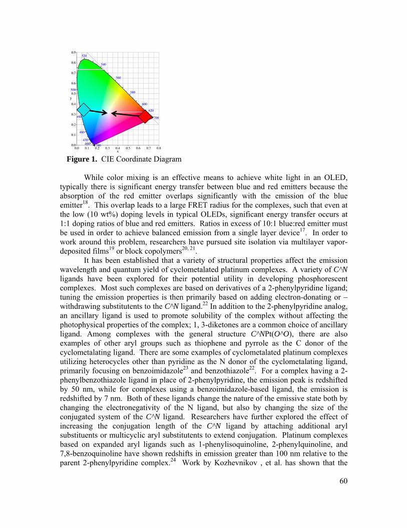
Figure 1. CIE Coordinate Diagram While color mixing is an effective means to achieve white light in an OLED,
typically there is significant energy transfer between blue and red emitters because the absorption of the red emitter overlaps significantly with the emission of the blue emitter18. This overlap leads to a large FRET radius for the complexes, such that even at the low (10 wt%) doping levels in typical OLEDs, significant energy transfer occurs at 1:1 doping ratios of blue and red emitters. Ratios in excess of 10:1 blue:red emitter must be used in order to achieve balanced emission from a single layer device17. In order to work around this problem, researchers have pursued site isolation via multilayer vapor-deposited films19 or block copolymers20, 21.
It has been established that a variety of structural properties affect the emission wavelength and quantum yield of cyclometalated platinum complexes. A variety of C^N ligands have been explored for their potential utility in developing phosphorescent complexes. Most such complexes are based on derivatives of a 2-phenylpyridine ligand; tuning the emission properties is then primarily based on adding electron-donating or –withdrawing substitutents to the C^N ligand.22 In addition to the 2-phenylpyridine analog, an ancillary ligand is used to promote solubility of the complex without affecting the photophysical properties of the complex; 1, 3-diketones are a common choice of ancillary ligand. Among complexes with the general structure C^NPt(O^O), there are also examples of other aryl groups such as thiophene and pyrrole as the C donor of the cyclometalating ligand. There are some examples of cyclometalated platinum complexes utilizing heterocycles other than pyridine as the N donor of the cyclometalating ligand, primarily focusing on benzoimidazole23 and benzothiazole22. For a complex having a 2-phenylbenzothiazole ligand in place of 2-phenylpyridine, the emission peak is redshifted by 50 nm, while for complexes using a benzoimidazole-based ligand, the emission is redshifted by 7 nm. Both of these ligands change the nature of the emissive state both by changing the electronegativity of the N ligand, but also by changing the size of the conjugated system of the C^N ligand. Researchers have further explored the effect of increasing the conjugation length of the C^N ligand by attaching additional aryl substituents or multicyclic aryl substitutents to extend conjugation. Platinum complexes based on expanded aryl ligands such as 1-phenylisoquinoline, 2-phenylquinoline, and 7,8-benzoquinoline have shown redshifts in emission greater than 100 nm relative to the parent 2-phenylpyridine complex.24 Work by Kozhevnikov , et al. has shown that the
60
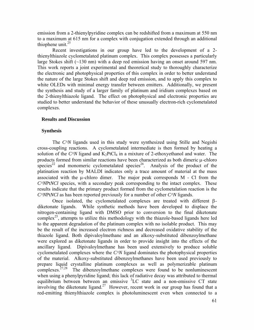
61
emission from a 2-thienylpyridine complex can be redshifted from a maximum at 550 nm to a maximum at 615 nm for a complex with conjugation extended through an additional thiophene unit.25
Recent investigations in our group have led to the development of a 2-thienylthiazole cyclometalated platinum complex. This complex possesses a particularly large Stokes shift (~130 nm) with a deep red emission having an onset around 597 nm. This work reports a joint experimental and theoretical study to thoroughly characterize the electronic and photophysical properties of this complex in order to better understand the nature of the large Stokes shift and deep red emission, and to apply this complex to white OLEDs with minimal energy transfer between emitters. Additionally, we present the synthesis and study of a larger family of platinum and iridium complexes based on the 2-thienylthiazole ligand. The effect on photophysical and electronic properties are studied to better understand the behavior of these unusually electron-rich cyclometalated complexes.
Results and Discussion Synthesis The C^N ligands used in this study were synthesized using Stille and Negishi
cross-coupling reactions. A cyclometalated intermediate is then formed by heating a solution of the C^N ligand and K2PtCl4 in a mixture of 2-ethoxyethanol and water. The products formed from similar reactions have been characterized as both dimeric μ-chloro species22 and monomeric cyclometalated species26. Analysis of the product of the platination reaction by MALDI indicates only a trace amount of material at the mass associated with the μ-chloro dimer. The major peak corresponds M - Cl from the C^NPtNCl species, with a secondary peak corresponding to the intact complex. These results indicate that the primary product formed from the cyclometalation reaction is the C^NPtNCl as has been reported previously for a number of other C^N ligands.
Once isolated, the cyclometalated complexes are treated with different β-diketonate ligands. While synthetic methods have been developed to displace the nitrogen-containing ligand with DMSO prior to conversion to the final diketonate complex25, attempts to utilize this methodology with the thiazole-based ligands here led to the apparent degradation of the platinum complex with no isolable product. This may be the result of the increased electron richness and decreased oxidative stability of the thiazole ligand. Both dipivaloylmethane and an alkoxy-substituted dibenzoylmethane were explored as diketonate ligands in order to provide insight into the effects of the ancillary ligand. Dipivaloylmethane has been used extensively to produce soluble cyclometalated complexes where the C^N ligand dominates the photophysical properties of the material. Alkoxy-substituted dibenzoylmethanes have been used previously to prepare liquid crystalline platinum complexes as well as polymerizable platinum complexes.27,28 The dibenzoylmethane complexes were found to be nonluminescent when using a phenylpyridine ligand; this lack of radiative decay was attributed to thermal equilibrium between between an emissive 3LC state and a non-emissive CT state involving the diketonate ligand.27 However, recent work in our group has found that a red-emitting thienylthiazole complex is photoluminescent even when connected to a

dibenzoylmethane derivative. This is presumably because the 3LC state is too low to interact significantly with the deactivating CT state. Previous work on iridium-based complexes has found that emission for higher-energy complexes is diminished when dibenzoylmethane ancillary ligands are used, while emission from lower-energy C^N ligands is not diminished by use of this low energy ancillary ligand.9
The complexes PtTZ(dpm) and PtTTZT were prepared and isolated as shown in Scheme 1. PtTTZ(dbm) could be prepared, but attempts to isolate by recrystallization led to co-precipitation of an impurity, most likely the unmetalated TTZ ligand. Additionally, an iridium-based analog Ir(TZ)2acac was prepared as shown in Scheme 2 in order to better understand the effect of the metal center on photophysical properties.
Scheme 1. Synthesis of Cyclometalating Ligands and Pt Complexes
62
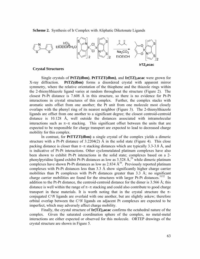
Scheme 2. Synthesis of Ir Complex with Aliphatic Diketonate Ligands
Crystal Structures
Single crystals of PtTZ(dbm), PtTTZT(dbm), and Ir(TZ)2acac were grown for X-ray diffraction. PtTZ(dbm) forms a disordered crystal with apparent mirror symmetry, where the relative orientation of the thiophene and the thiazole rings within the 2-thienylthiazole ligand varies at random throughout the structure (Figure 2). The closest Pt-Pt distance is 7.608 Å in this structure, so there is no evidence for Pt-Pt interactions in crystal structures of this complex. Further, the complex stacks with aromatic units offset from one another; the Pt unit from one molecule most closely overlaps with the phenyl ring of its nearest neighbor (Figure 3). The 2-thienylthiazole ligands are offset from one another to a significant degree; the closest centroid-centroid distance is 10.128 Å, well outside the distances associated with intramolecular interactions such as π−π stacking. This significant offset between the units that are expected to be responsible for charge transport are expected to lead to decreased charge mobility for this complex.
In contrast, for PtTTZT(dbm) a single crystal of the complex yields a dimeric structure with a Pt-Pt distance of 3.2204(2) Å in the solid state (Figure 4). This close packing distance is closer than π−π stacking distances which are typically 3.3-3.8 Å, and is indicative of Pt-Pt interactions. Other cyclometalated platinum complexes have also been shown to exhibit Pt-Pt interactions in the solid state; complexes based on a 2-phenylpyridine ligand exhibit Pt-Pt distances as low as 3.528 Å,29 while dimeric platinum complexes have shown Pt-Pt distances as low as 2.834 Å30. Previously reported platinum complexes with Pt-Pt distances less than 3.3 Å show significantly higher charge carrier mobilities than Pt complexes with Pt-Pt distances greater than 3.3 Å; no significant charge carrier mobilities are found for the structures with larger Pt-Pt distances.3132 In addition to the Pt-Pt distance, the centroid-centroid distance for the dimer is 3.566 Å; this distance is well within the range of π−π stacking and could also contribute to good charge transport in these materials. It is worth noting that in the crystal structure the π-conjugated C^N ligands are overlaid with one another, but are slightly askew; therefore orbital overlap between the C^N ligands on adjacent Pt complexes are expected to be imperfect, which may adversely affect charge mobility.
Finally, the crystal structure of Ir(TZ)2acac confirms the octahedral nature of the complex. Given the saturated coordination sphere of the complex, no metal-metal interactions are either expected or observed for this molecule. ORTEP drawings of the crystal structure are shown in Figure 5.
63
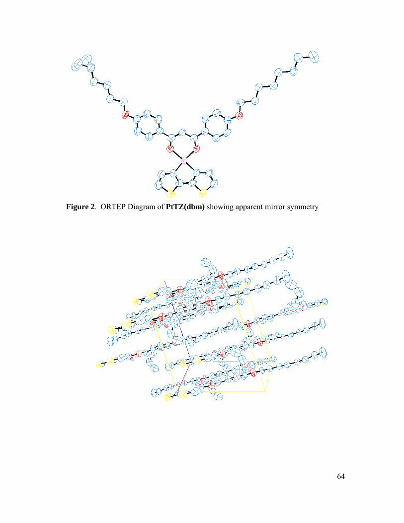
Figure 2. ORTEP Diagram of PtTZ(dbm) showing apparent mirror symmetry
64

Figure 3. ORTEP Diagram of Unit Cell of PtTZ(dbm) Crystals
65

Figure 4. ORTEP Diagram of PtTTZT(dbm) Crystals
66
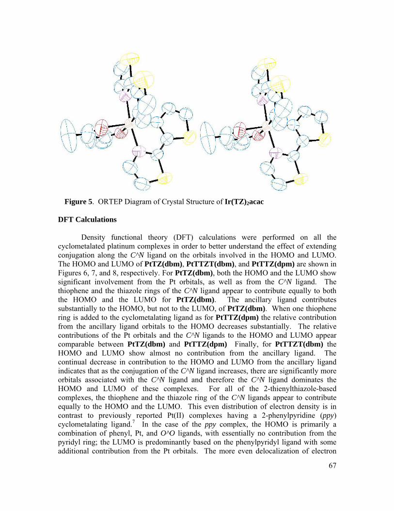
Figure 5. ORTEP Diagram of Crystal Structure of Ir(TZ)2acac
DFT Calculations Density functional theory (DFT) calculations were performed on all the cyclometalated platinum complexes in order to better understand the effect of extending conjugation along the C^N ligand on the orbitals involved in the HOMO and LUMO. The HOMO and LUMO of PtTZ(dbm), PtTTZT(dbm), and PtTTZ(dpm) are shown in Figures 6, 7, and 8, respectively. For PtTZ(dbm), both the HOMO and the LUMO show significant involvement from the Pt orbitals, as well as from the C^N ligand. The thiophene and the thiazole rings of the C^N ligand appear to contribute equally to both the HOMO and the LUMO for PtTZ(dbm). The ancillary ligand contributes substantially to the HOMO, but not to the LUMO, of PtTZ(dbm). When one thiophene ring is added to the cyclometalating ligand as for PtTTZ(dpm) the relative contribution from the ancillary ligand orbitals to the HOMO decreases substantially. The relative contributions of the Pt orbitals and the C^N ligands to the HOMO and LUMO appear comparable between PtTZ(dbm) and PtTTZ(dpm) Finally, for PtTTZT(dbm) the HOMO and LUMO show almost no contribution from the ancillary ligand. The continual decrease in contribution to the HOMO and LUMO from the ancillary ligand indicates that as the conjugation of the C^N ligand increases, there are significantly more orbitals associated with the C^N ligand and therefore the C^N ligand dominates the HOMO and LUMO of these complexes. For all of the 2-thienylthiazole-based complexes, the thiophene and the thiazole ring of the C^N ligands appear to contribute equally to the HOMO and the LUMO. This even distribution of electron density is in contrast to previously reported Pt(II) complexes having a 2-phenylpyridine (ppy) cyclometalating ligand.7 In the case of the ppy complex, the HOMO is primarily a combination of phenyl, Pt, and O^O ligands, with essentially no contribution from the pyridyl ring; the LUMO is predominantly based on the phenylpyridyl ligand with some additional contribution from the Pt orbitals. The more even delocalization of electron
67

density across the C^N ligands reported here may minimize the charge-transfer character in excitations.
Figure 6. HOMO (top) and LUMO (bottom) of PtTZ(dbm)
68
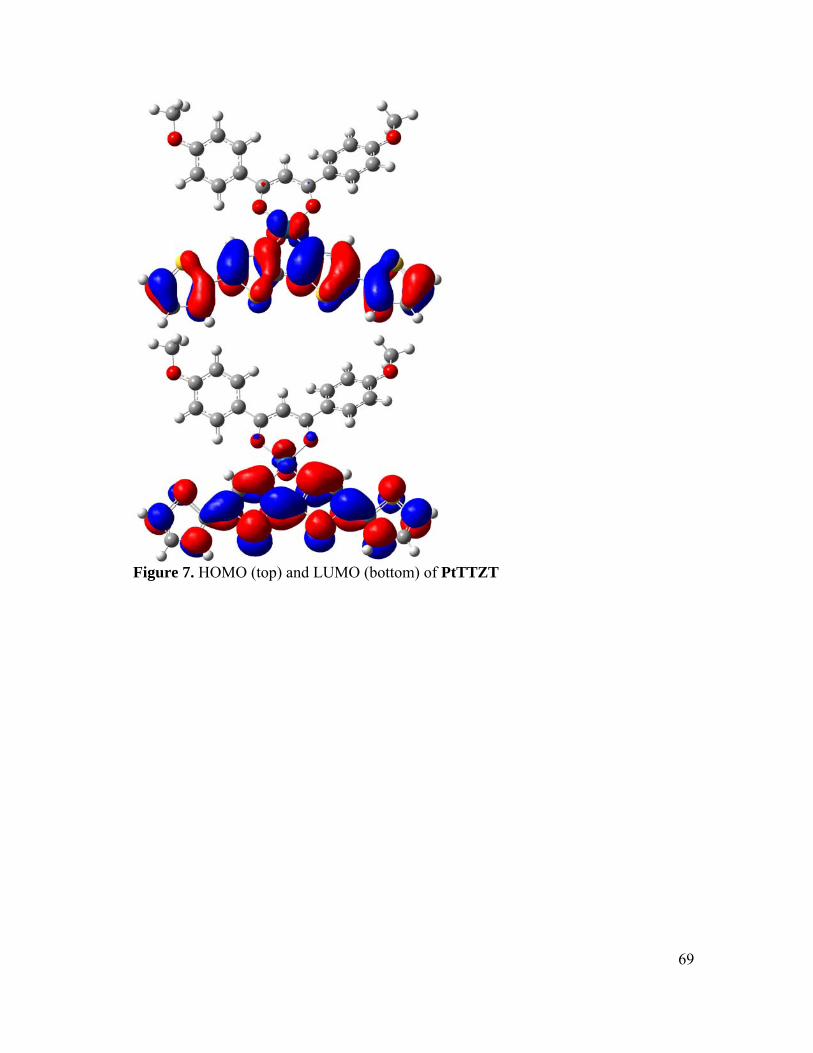
Figure 7. HOMO (top) and LUMO (bottom) of PtTTZT
69

Figure 8. HOMO (top) and LUMO (bottom) of PtTTZ(dpm) The excitation spectrum of each complex was also modeled using time-dependent
DFT (TDDFT) in order to better understand the nature of the electronic transitions that are observed spectroscopically. For all of the complexes, a lower energy (>550nm) triplet transition exists that is a predominantly HOMO-LUMO transition, with a triplet spin state. All the lowest energy transitions have an oscillator strength of zero, and redshift with increasing conjugation along the C^N ligand: PtTZ(dbm) (597 nm), PtTTZ(dpm) (733 nm), PtTTZT(dbm) (815 nm). In looking at increasingly higher energy transitions, PtTZ(dbm), the next three higher energy transitions are also triplet in nature and range from in wavelength from 474 nm to 410 nm. At 410 nm there also exists a transition that is singlet in nature, which is predominantly made up of a HOMO-LUMO transition. The difference in energy between the singlet and triplet excitations is 0.002 eV, well below thermal energy at room temperature, which is approximately 0.025 eV. This small energy difference between the singlet and triplet energies indicates that upon excitation, the two states are well mixed and intersystem crossing should therefore occur readily. In contrast, the next higher energy transitions of PtTTZ(dpm) are at 454 nm and 448 nm, where the transition at 454 nm corresponds to a triplet excitation and the transition at 448 nm corresponds to a predominantly HOMO-LUMO transition that is singlet in nature. These transitions have an energy difference of 0.034 eV, which is somewhat greater than the thermal energy at room temperature. This suggests that some
70
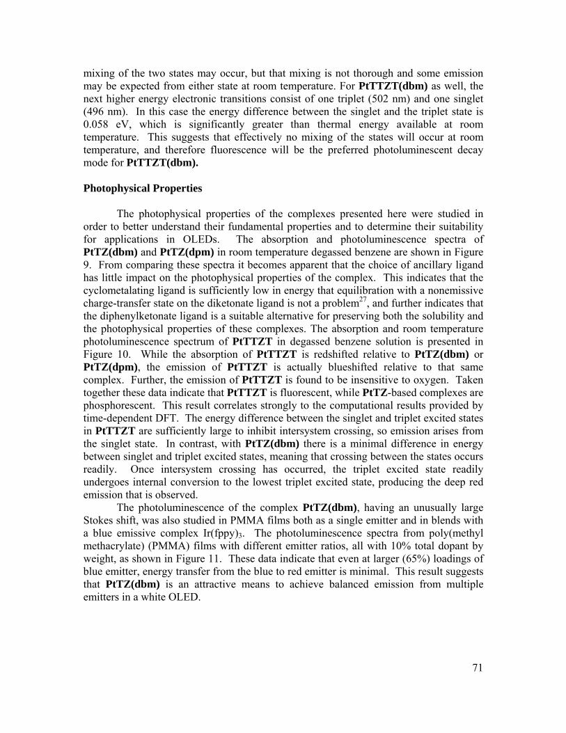
71
mixing of the two states may occur, but that mixing is not thorough and some emission may be expected from either state at room temperature. For PtTTZT(dbm) as well, the next higher energy electronic transitions consist of one triplet (502 nm) and one singlet (496 nm). In this case the energy difference between the singlet and the triplet state is 0.058 eV, which is significantly greater than thermal energy available at room temperature. This suggests that effectively no mixing of the states will occur at room temperature, and therefore fluorescence will be the preferred photoluminescent decay mode for PtTTZT(dbm).
Photophysical Properties
The photophysical properties of the complexes presented here were studied in order to better understand their fundamental properties and to determine their suitability for applications in OLEDs. The absorption and photoluminescence spectra of PtTZ(dbm) and PtTZ(dpm) in room temperature degassed benzene are shown in Figure 9. From comparing these spectra it becomes apparent that the choice of ancillary ligand has little impact on the photophysical properties of the complex. This indicates that the cyclometalating ligand is sufficiently low in energy that equilibration with a nonemissive charge-transfer state on the diketonate ligand is not a problem27, and further indicates that the diphenylketonate ligand is a suitable alternative for preserving both the solubility and the photophysical properties of these complexes. The absorption and room temperature photoluminescence spectrum of PtTTZT in degassed benzene solution is presented in Figure 10. While the absorption of PtTTZT is redshifted relative to PtTZ(dbm) or PtTZ(dpm), the emission of PtTTZT is actually blueshifted relative to that same complex. Further, the emission of PtTTZT is found to be insensitive to oxygen. Taken together these data indicate that PtTTZT is fluorescent, while PtTZ-based complexes are phosphorescent. This result correlates strongly to the computational results provided by time-dependent DFT. The energy difference between the singlet and triplet excited states in PtTTZT are sufficiently large to inhibit intersystem crossing, so emission arises from the singlet state. In contrast, with PtTZ(dbm) there is a minimal difference in energy between singlet and triplet excited states, meaning that crossing between the states occurs readily. Once intersystem crossing has occurred, the triplet excited state readily undergoes internal conversion to the lowest triplet excited state, producing the deep red emission that is observed.
The photoluminescence of the complex PtTZ(dbm), having an unusually large Stokes shift, was also studied in PMMA films both as a single emitter and in blends with a blue emissive complex Ir(fppy)3. The photoluminescence spectra from poly(methyl methacrylate) (PMMA) films with different emitter ratios, all with 10% total dopant by weight, as shown in Figure 11. These data indicate that even at larger (65%) loadings of blue emitter, energy transfer from the blue to red emitter is minimal. This result suggests that PtTZ(dbm) is an attractive means to achieve balanced emission from multiple emitters in a white OLED.

Figure 9. Absorption (Black) and Photoluminescence (Red) of PtTZ(dpm) (dashed
lines) and PtTZ(dbm) (solid lines) in Room-Temperature Benzene
Figure 10. Absorption (Black) and Photoluminescence (Red) of PtTTZT in Room-
Temperature Benzene
72

Figure 11. Photoluminescence from PMMA Films With Varying Amounts of
Ir(fppy)3 and PtTZ(dbm) Considering that Ir-based emitters are typically favored in OLEDs for their
shorter lifetimes, the properties of complex Ir(TZ)2acac were also studied to determine its potential suitability as a red emitter without the ability to undergo FRET from a blue emitter. The absorption and photoluminescence spectra of Ir(TZ)2acac in room-temperature THF solution are overlaid in Figure 12. The absorption spectrum of Ir(TZ)2acac extends slightly farther into the red than the absorption spectrum of PtTZ(dbm), which may be a problem for inhibiting energy transfer for white OLEDs. To further illustrate this point, the absorption spectra of Ir(TZ)2acac, PtTZ(dbm) and the emission spectrum of a common blue emitter Ir(fppy)3 are overlaid in Figure 13. The overlap between Ir(TZ)2acac absorption and Ir(fppy)3 emission are clearly much larger than the overlap between PtTZ(dbm) absorption and Ir(fppy)3 emission. This indicates that Ir(TZ)2acac is not suitable for inhibiting FRET between blue and red emitters. Use of the platinum center is necessary to achieve this large Stokes shift having no overlap with blue emission.
73
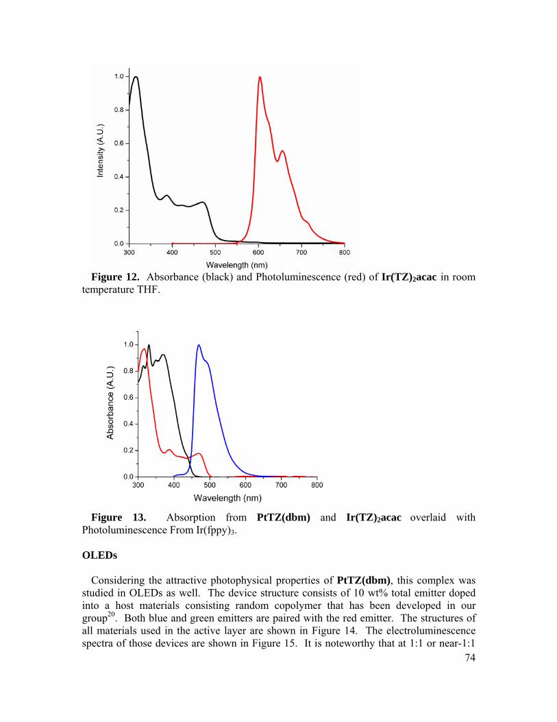
Figure 12. Absorbance (black) and Photoluminescence (red) of Ir(TZ)2acac in room
temperature THF.
Figure 13. Absorption from PtTZ(dbm) and Ir(TZ)2acac overlaid with
Photoluminescence From Ir(fppy)3.
OLEDs
Considering the attractive photophysical properties of PtTZ(dbm), this complex was studied in OLEDs as well. The device structure consists of 10 wt% total emitter doped into a host materials consisting random copolymer that has been developed in our group20. Both blue and green emitters are paired with the red emitter. The structures of all materials used in the active layer are shown in Figure 14. The electroluminescence spectra of those devices are shown in Figure 15. It is noteworthy that at 1:1 or near-1:1 74
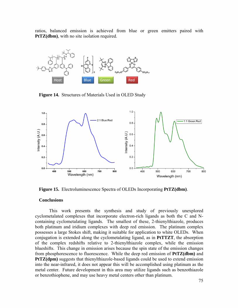
ratios, balanced emission is achieved from blue or green emitters paired with PtTZ(dbm), with no site isolation required.
Figure 14. Structures of Materials Used in OLED Study
Figure 15. Electroluminescence Spectra of OLEDs Incorporating PtTZ(dbm). Conclusions This work presents the synthesis and study of previously unexplored
cyclometalated complexes that incorporate electron-rich ligands as both the C and N-containing cyclometalating ligands. The smallest of these, 2-thienylthiazole, produces both platinum and iridium complexes with deep red emission. The platinum complex possesses a large Stokes shift, making it suitable for application to white OLEDs. When conjugation is extended along the cyclometalating ligand, as in PtTTZT, the absorption of the complex redshifts relative to 2-thienylthiazole complex, while the emission blueshifts. This change in emission arises because the spin state of the emission changes from phosphorescence to fluorescence. While the deep red emission of PtTZ(dbm) and PtTZ(dpm) suggests that thienylthiazole-based ligands could be used to extend emission into the near-infrared, it does not appear this will be accomplished using platinum as the
75
metal center. Future development in this area may utilize ligands such as benzothiazole or benzothiophene, and may use heavy metal centers other than platinum.

76
xperimental
als were purchased from commercial sources and used without purification unless otherwise stated. 2-(2'-Thienyl)thiazole, 5-Bromo-2-(5-bromothiophen-2-yl)-1,3-th
lumina
lets or
l, 1 eq) was dissolved in 20 mL H2O and 5-bromo-2-(5-bromothiophen-2-yl)-1,3-thiazole (0.7 g, 2.2 mmol, 2 eq) was di
hene (5.57 g, 33.53 mmol, 1.1 eq) was dissolved in anhydrous THF (150 mL) and the solution was co s
E Synthesis All chemic
iazole, and (2Z)-3-hydroxy-1,3-bis[4-(octyloxy)phenyl]prop-2-en-1-one were synthesized according to previously described procedures. Tetrahydrofuran (THF), N, N-dimethylformamide (DMF), and toluene were dried by passing through neutral aprior to use. All small molecules were characterized by 1H NMR (400 MHz) and 13C NMR (100 MHz) on a Bruker AVB 400 or AVQ 400. All NMR spectra were referenced to TMS. High-resolution mass spectroscopy and elemental analysis (CHN) were performed at the University of California, Berkeley Department of Chemistry analytical services laboratory. IR spectra were recorded on a Varian 3100 FT-IR as KBr pelas solid or liquid films drop-cast on KBr discs. Melting points are uncorrected. Column chromatography was performed with silica (230x400 mesh).
PtTZ(dpm): Potassium tetrachloroplatinate (.45 g, 1.1 mmo
ssolved separately in 70 mL ethoxyethanol. The solutions were combined and heated to 90oC overnight under nitrogen. The reaction mixture was then cooled to room temperature and poured over 90 mL H2O. A dark green precipitate was collected by filtration, rinsed with water and methanol, then dried under vacuum overnight (0.6 g). It was used in subsequent steps without additional purification. The precipitate from this reaction (0.2 g, 0.25 mmol, 1 eq) was dissolved in 2.5 mL of 2-ethoxyethanol. To this solution was added sodium carbonate (1.06 g, 2.5 mmol, 10 eq) and dipivaloylmethane (0.14 g, 0.75 mmol, 3 eq). The reaction was stirred and heated 100 oC for 18 hours. The reaction mixture was cooled, and water and dichloromethane added. The product was extracted into the organic layer, then the organic layers combined and washed with water (3 x 20 mL) to remove the 2-ethoxyethanol, and the organic layer dried over MgSO4. Solvent was removed under reduced pressure, and then the oily residue was subjected to column chromatography (20% hexanes in CH2Cl2, silica). The product eluted as the first, photoluminescent spot. The fractions were collected and solvent removed to obtain the product as an orange solid with m.p. 171-173oC in 32% yield. 1H NMR (400 MHz, (CD3)2CO): 7.86 (d, 1H); 7.71 (d, 1H); 7.64 (d, 1H); 7.13 (d, 1H); 5.95 (s, 1H); 1.27 (s; 18H) HRMS (FAB) Calcd. 543.0797 Found 543.0800. CHN for C18H23NO2PtS2 Calcd. 39.70% C, 4.26% H, 2.57% N. Found 39.82% C, 4.46% H, 2.72% N.
2-[5-(thiophen-2-yl)thiophen-2-yl]-1,3-thiazole (TTZ): 2, 2’-bithiop
oled to -78oC and treated dropwise with a 2.5 M solution of n-butyllithium in hexane(13.4 mL, 33.53 mmol, 1.1 eq). The solution was stirred with cooling to -78oC for 1 hour, then anhydrous zinc chloride (6.85 g, 50.29 mmol, 1.65 eq) was added in one
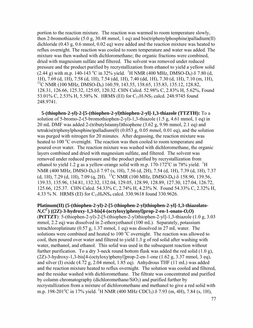
77
, m(II)
o
d (d,
en-2-yl)-2-[5-(thiophen-2-yl)thiophen-2-yl]-1,3-thiazole (TTZTH): To a solution of 5-bromo-2-(5-bromothiophen-2-yl)-1,3-thiazole (1.5 g, 4.61 mmol, 1 eq) in 20
nic
H , 7.37
,
,
,3-thiazolato-N,C ) ((2Z)-3-hydroxy-1,3-bis[4-(octyloxy)phenyl]prop-2-en-1-onato-O,O)
.03 m
to ith
), ,
,
.84 (s, 1H),
portion to the reaction mixture. The reaction was warmed to room temperature slowlythen 2-bromothiazole (5.0 g, 30.48 mmol, 1 eq) and bis(triphenylphosphine)palladiudichloride (0.43 g, 0.6 mmol, 0.02 eq) were added and the reaction mixture was heated treflux overnight. The reaction was cooled to room temperature and water was added. The mixture was then washed with dichloromethane; the organic fractions were combined, dried with magnesium sulfate and filtered. The solvent was removed under reduced pressure and the product purified by recrystallization from ethanol to yield a yellow soli(2.44 g) with m.p. 140-143 oC in 32% yield. 1H NMR (400 MHz, DMSO-D6) δ 7.80 1H), 7.69 (d, 1H), 7.58 (d, 1H), 7.54 (dd, 1H), 7.40 (dd, 1H), 7.30 (d, 1H), 7.10 (m, 1H), 13C NMR (100 MHz, DMSO-D6) 160.59, 143.55, 138.65, 135.83, 135.12, 128.82, 128.31, 126.66, 125.32, 125.05, 120.32. CHN Calcd. 52.98% C, 2.83% H, 5.62%, Found 53.01% C, 2.53% H, 5.58% N. HRMS (EI) for C11H7NS3 calcd. 248.9745 found 248.9741.
5-(thioph
mL DMF was added 2-(tributylstannyl)thiophene (3.62 g, 9.96 mmol, 2.1 eq) and tetrakis(triphenylphosphine)palladium(0) (0.053 g, 0.05 mmol, 0.01 eq), and the solutionwas purged with nitrogen for 20 minutes. After degassing, the reaction mixture was heated to 100 oC overnight. The reaction was then cooled to room temperature and poured over water. The reaction mixture was washed with dichloromethane, the orgalayers combined and dried with magnesium sulfate, and filtered. The solvent was removed under reduced pressure and the product purified by recrystallization from ethanol to yield 1.2 g as a yellow-orange solid with m.p. 170-172oC in 78% yield. 1
NMR (400 MHz, DMSO-D6) δ 7.97 (s, 1H), 7.56 (d, 2H), 7.54 (d, 1H), 7.39 (d, 1H)(d, 1H), 7.29 (d, 1H), 7.09 (q, 2H). 13C NMR (100 MHz, DMSO-D6) δ 158.90, 139.56139.33, 135.96, 134.81, 132.32, 132.04, 129.05, 128.99, 128.89, 127.30, 127.04, 126.72, 125.66, 125.37. CHN Calcd. 54.33% C, 2.74% H, 4.23% N. Found 54.33% C, 2.32% H4.33 % N. HRMS (EI) for C15H9NS4 calcd. 330.9618 found 330.9626.
Platinum(II) (5-(thiophen-2-yl)-2-[5-(thiophen-2-yl)thiophen-2-yl]-1
2'
(PtTTZT): 5-(thiophen-2-yl)-2-[5-(thiophen-2-yl)thiophen-2-yl]-1,3-thiazole (1.0 g, 3mmol, 2.2 eq) was dissolved in 2-ethoxyethanol (100 mL). Separately, potassiutetrachloroplatinate (0.57 g, 1.37 mmol, 1 eq) was dissolved in 27 mL water. The solutions were combined and heated to 100 oC overnight. The reaction was allowedcool, then poured over water and filtered to yield 1.3 g of red solid after washing wwater, methanol, and ethanol. This solid was used in the subsequent reaction without further purification. To a dry 3-neck round bottom flask was added the red solid (1.0 g(2Z)-3-hydroxy-1,3-bis[4-(octyloxy)phenyl]prop-2-en-1-one (1.62 g, 3.37 mmol, 3 eq)and silver (I) oxide (4.72 g, 2.04 mmol, 1.85 eq). Anhydrous THF (11 mL) was added and the reaction mixture heated to reflux overnight. The solution was cooled and filteredand the residue washed with dichloromethane. The filtrate was concentrated and purified by column chromatography (dichloromethane/SiO2) and purified further by recrystallization from a mixture of dichloromethane and methanol to give a red solid with m.p. 198-201oC in 17% yield. 1H NMR (400 MHz CDCl3) δ 7.93 (m, 4H), 7

78
3
lock 0.20 x 0.18 x 0.15 mm in size was mounted on a Cryoloop with Paratone oil. eam at 118(2) K using phi and omega scans.
te 0.15 x 0.12 x 0.10 mm in size was mounted on a Cryoloop with Paratone ream at 133(2) K using phi and omega scans.
7.28 (m, 1H), 7.26 (m, 1H), 7.23 (m, 2H), 7.10 (1H), 7.04 (m, 2H), 6.96 (m, 4H), 6.58 (s, 1H), 4.02 (m, 4H), 1.80 (m, 4H), 1.49 – 1.31 (m, 20H), 0.88 (t, 6H) HRMS (FAB+) for C46H51NO4PtS4 Calcd. 1005.2382. Found 1005.2396. CHN Calcd. 54.96% C, 5.11 % H, 1.39% N. Found 55.19% C, 5.05% H, 1.50% N.
Ir(TZ)2acac: 2-(2'-Thienyl)thiazole (3.0 g, 17.9 mmol, 2.25 eq) was dissolved in 240 mL 2-methoxyethanol, while IrCl (2.38 g, 7.97 mmol, 1 eq) was dissolved separately in 80 mL water. The solutions were combined and heated overnight to 100 oC. The reaction was then cooled to room temperature and poured over water. The green precipitate was collected, washed with water and methanol, dried under vacuum overnight, and used without further purification in the next step. The green solid (1.0 g, 0.89 mmol, eq), and sodium carbonate (0.218 g, 2.05 mmol, 2.3 eq) were added to 2-ethoxyethanol (45 mL), and the solution was degassed by three freeze-pump-thaw cycles. Following this, acetylacetone (0.223 g, 2.23 mmol, 2.5 eq) was added and the solution heated to 120 oC overnight. The reaction mixture was cooled to room temperature. Dichloromethane and water were added; the reaction mixture was extracted into dichloromethane, and the organic layers washed with water to remove the methoxyethanol. The organic layers were dried over NaSO4, filtered, and the solvent removed under reduced pressure. The product was purified using column chromatography (dichloromethane, silica) and recrystallized by slow diffusion of dichloromethane and hexanes to give a red solid with m.p. 240-242oC in 20% yield. 1H NMR (400 MHz, CDCl3) δ 7.53 (d, 2H), 7.2 (m, 4H), 6.13 (d, 1H), 5.23 (s, 1H), 1.83 (s, 1H). HRMS (EI) calcd. for C19H15IrN2O2S4 623.9645 found, 623.9646. CHN Calcd. 36.58% C, 2.42% H, 4.49% N. Found 36.34% C, 2.14% H, 4.42% N.
X-Ray Crystallography
PtTZ:
A red bData were collected in a nitrogen gas strCrystal-to-detector distance was 60 mm and exposure time was 10 seconds per frame using a scan width of 0.5°. Data collection was 99.4% complete to 25.00° in θ. A total of 32114 reflections were collected covering the indices, -13<=h<=13, -15<=k<=15, -17<=l<=17. 6644 reflections were found to be symmetry independent, with an Rint of 0.0202. Indexing and unit cell refinement indicated a primitive, triclinic lattice. The space group was found to be P-1 (No. 2). The data were integrated using the Bruker SAINT software program and scaled using the SADABS software program. Solution by direct methods (SIR-97) produced a complete heavy-atom phasing model consistent with the proposed structure. All non-hydrogen atoms were refined anisotropically by full-matrix least-squares (SHELXL-97). All hydrogen atoms were placed using a riding model. Their positions were constrained relative to their parent atom using the appropriate HFIX command in SHELXL-97.
PtTTZT:
A red plaoil. Data were collected in a nitrogen gas st

79
C
2
plate 0.15 x 0.12 x 0.10 mm in size was mounted on a Cryoloop with llected in a nitrogen gas stream at 133(2) K using phi and
ega
ructure, the molecular geometry was optimized nl2dz basis set on the platinum atoms using
G ssia
tion, substrates with ITO on glass were patterned as 2 mm Ω/sq. The substrates were cleaned by sonication in a
rystal-to-detector distance was 60 mm and exposure time was 10 seconds per frame using a scan width of 0.3°. Data collection was 99.5% complete to 25.00° in θ. A total of 50450 reflections were collected covering the indices, -16<=h<=16, -18<=k<=17, -25<=l<=25. 15641 reflections were found to be symmetry independent, with an Rint of 0.0192. Indexing and unit cell refinement indicated a primitive, triclinic lattice. The space group was found to be P-1 (No. 2). The data were integrated using the Bruker SAINT software program and scaled using the SADABS software program. Solution by direct methods (SIR-97) produced a complete heavy-atom phasing model consistent with the proposed structure. All non-hydrogen atoms were refined anisotropically by full-matrix least-squares (SHELXL-97). All hydrogen atoms were placed using a riding model. Their positions were constrained relative to their parent atom using the appropriate HFIX command in SHELXL-97.
(TZ) acac: Ir
A red Paratone oil. Data were coom scans. Crystal-to-detector distance was 60 mm and exposure time was 10 seconds per frame using a scan width of 0.3°. Data collection was 100.0% complete to 25.00° in θ. A total of 29421 reflections were collected covering the indices, -28<=h<=28, -32<=k<=32, -9<=l<=9. 4816 reflections were found to be symmetry independent, with an Rint of 0.0281. Indexing and unit cell refinement indicated an I-centered, orthorhombic lattice. The space group was found to be Iba2 (No. 45). The data were integrated using the Bruker SAINT software program and scaled using the SADABS software program. Solution by direct methods (SIR-2004) produced a complete heavy-atom phasing model consistent with the proposed structure. All non-hydrogen atoms were refined anisotropically by full-matrix least-squares (SHELXL-97). All hydrogen atoms were placed using a riding model. Their positions were constrained relative to their parent atom using the appropriate HFIX command in SHELXL-97.
Density Function Theory Calculations
Starting from the X-ray crystal stat the DFT level with B3LYP/6-31G(d) and la
au n 03.33 Any higher alkyl chains were replaced with methyl groups to expedite calculation time while assuming they are not involved in the frontier orbitals of the molecule. Using this initial geometry a global energy minimum was found by optimizing several starting thiophene dihedral angle geometries and comparing total energies of each minimum found. The planar molecular geometry shown here was the global energy minimum. The resulting molecular orbitals were visualized at 0.02 isovalue. A time dependant DFT calculation was run on this geometry in order to obtain the excitation energies and nature of the transitions.
OLED Device Fabrication
Prior to device fabricawide stripes with resistivity of 20

80
ared
f 1 /s,
the
etector response.
cht, M. Chem. Rev. 2010, 110, 576-623. Dalton Trans. 2009, 6267-6279.
, 171-174.
F.; Kwong, R.; Tsyba, hem. 2001, 40, 1704-
6. e, A. D.; Cram, D. J., Eds.; Topics in Current Chemistry; Springer Berlin /
7. , 3763-3770.
.; Thompson, M. E. J. Am. Chem. Soc. 2001, 123,
10. 19, 84-95.
388-15389.
rg. Chem. 2005, 44, 7992-8003.
soap solution; rinsed with deionized water; boiled in trichloroethylene, acetone, and ethanol for 5 min each; and then blown dry under a stream of nitrogen gas. Finally, the substrates were treated with UV/ozone for 10 min. The organic active layer was prepby spin-casting solutions at 3000 rpm for 60 s. The solutions were filtered using 0.2 μm poly(vinylidene difluoride) filters prior to use. The thickness of the organic layer was monitored by ellipsometry. After spin-casting, a shadow mask with a 2 mm wide stripe was placed onto the substrates perpendicular to the ITO stripes. A cathode consisting onm thick LiF and 100 nm thick aluminum was then deposited at a rate of 0.2 and 4−5 Årespectively. OLEDs were formed at the 2 × 2 mm squares where the ITO (anode) and Al (cathode) stripes intersect. The devices were tested in air within 2 h of fabrication. The electrical and optical intensity characteristics of the devices were measured with a Keithly 2400 sourcemeter/2000 multimeter coupled to a Newport 1835-C optical meter,equipped with a UV-818 Si photodetector. Only light emitted from the front face ofdevice was collected and used in subsequent efficiency calculations. The electroluminescence (EL) spectra were measured on a PTI QuantaMaster model C-60SEspectrofluorimeter equipped with a 928 PMT detector and corrected for dThe emission was found to be uniform throughout the area of each device. References
1. Albre2. Selander, N.; Szabo, K. J. 3. Martin, A.; van Koten, G. Adv. Mater. 1999, 114. Chou, P.; Chi, Y. Chem. Eur. J. 2007, 13, 380-395. 5. Lamansky, S.; Djurovich, P.; Murphy, D.; Abdel-Razzaq,
I.; Bortz, M.; Mui, B.; Bau, R.; Thompson, M. E. Inorg. C1711. Williams, J. In Photochemistry and Photophysics of Coordination Compounds II; MeijerHeidelberg, 2007; pp. 205-268. Djurovich, P. I.; Murphy, D.; Thompson, M. E.; Hernandez, B.; Gao, R.; Hunt, P. L.; Selke, M. Dalton Trans. 2007
8. He, L.; Qiao, J.; Duan, L.; Dong, G.; Zhang, D.; Wang, L.; Qiu, Y. Adv. Funct. Mater. 2009, 19, 2950-2960.
9. Lamansky, S.; Djurovich, P.; Murphy, D.; Abdel-Razzaq, F.; Lee, H.; Adachi, C.; Burrows, P. E.; Forrest, S. R4304-4312. Wang, Q.; Ding, J.; Ma, D.; Cheng, Y.; Wang, L.; Jing, X.; Wang, F. Adv. Funct. Mater. 2009,
11. Furuta, P. T.; Deng, L.; Garon, S.; Thompson, M. E.; Fréchet, J. M. J. J. Am. Chem. Soc. 2004, 126, 15
12. Sajoto, T.; Djurovich, P. I.; Tamayo, A.; Yousufuddin, M.; Bau, R.; Thompson, M. E.; Holmes, R. J.; Forrest, S. R. Ino
13. Ostrowski, J.; Susumu, K.; Robinson, M.; Therien, M.; Bazan, G. Adv. Mater. 2003, 15, 1296-1300.
14. Qiao, J.; Duan, L.; Tang, L.; He, L.; Wang, L.; Qiu, Y. J. Mater. Chem. 2009, 19,
81
chner, J.; Park, S. Y. J. Am. Chem. Soc. 2009, 131, 14043-14049.
18. . J.; Janssen, R. A. J. J. Phys. Chem. A 2007, 111,
ules 2007, 40, 8156-8161.
Inorg. Chem. 2002, 41, 3055-3066.
Hayden, L. E.; Kimyonok, A.; South, C. R.; Weck, M.; Kippelen, B.;
25. abel, M.; Yersin, H. Inorg.
26. , 4090-4093.
28. .; Muller, P.; Swager, T. M. J. Mater.
30. P. I.; Yousufuddin, M.; Bau, R.; Thompson, M. E. J.
g, T. Adv. Funct. Mater. 2004, 14,
32. J.; Xu, S.; Che, C. Angew. Chem. Int. Ed. 2008, 47, 9895-9899.
even, rone,
ts,
6573-6580. 15. Park, S.; Kwon, J. E.; Kim, S. H.; Seo, J.; Chung, K.; Park, S.; Jang, D.; Medina,
B. M.; Giers16. Adhikari, R. M.; Duan, L.; Hou, L.; Qiu, Y.; Neckers, D. C.; Shah, B. K. Chem.
Mater. 2009, 21, 4638-4644. 17. Hu, B.; Karasz, F. E. J. Appl. Phys. 2003, 93, 1995-2001.
Wasserberg, D.; Meskers, S. C1381-1388.
19. Laquai, F.; Park, Y.; Kim, J.; Basché, T. Macromol. Rapid Commun. 2009, 30, 1203-1231.
20. Ma, B.; Kim, B. J.; Deng, L.; Poulsen, D. A.; Thompson, M. E.; Frechet, J. M. J. Macromolec
21. Poulsen, D. A.; Kim, B. J.; Ma, B.; Zonte, C. S.; Fréchet, J. M. J. Adv. Mater. 2010, 22, 77-82.
22. Brooks, J.; Babayan, Y.; Lamansky, S.; Djurovich, P. I.; Tsyba, I.; Bau, R.; Thompson, M. E.
23. Li, H.; Ding, J.; Xie, Z.; Cheng, Y.; Wang, L. J. Organomet. Chem. 2009, 694, 2777-2785.
24. Cho, J.; Domercq, B.; Barlow, S.; Suponitsky, K. Y.; Li, J.; Timofeeva, T. V.; Jones, S. C.; Marder, S. R. Organometallics 2007, 26, 4816-4829. Kozhevnikov, D. N.; Kozhevnikov, V. N.; Ustinova, M. M.; Santoro, A.; Bruce, D. W.; Koenig, B.; Czerwieniec, R. ‚.; Fischer, T.; ZChem. 2009, 48, 4179-4189. Cho, J.; Suponitsky, K. Y.; Li, J.; Timofeeva, T. V.; Barlow, S.; Marder, S. R. J. Organomet. Chem. 2005, 690
27. Thomas, S.; Yagi, S.; Swager, T. J. Mater. Chem. 2005, 15, 2829-2835. Venkatesan, K.; Kouwer, P. H. J.; Yagi, SChem. 2008, 18, 400-407.
29. Chassot, L.; Mueller, E.; Von Zelewsky, A. Inorg. Chem. 1984, 23, 4249-4253. Ma, B.; Li, J.; Djurovich, Am. Chem. Soc. 2004, 127, 28-29.
31. Debije, M.; de Haas, M.; Warman, J.; Fontana, M.; Stutzmann, N.; Kristiansen, M.; Caseri, W.; Smith, P.; Hoffmann, S.; Søllin323-328. Yuen, M.; Roy, V.; Lu, W.; Kui, S.; Tong, G. S. M.; So, M.; Chui, S. S.; Muccini, M.; Ning,
33. Gaussian 03, Revision C.02, Frisch, M. J.; Trucks, G. W.; Schlegel, H. B.; Scuseria, G. E.; Robb, M. A.; Cheeseman, J. R.; Montgomery, Jr., J. A.; VrT.; Kudin, K. N.; Burant, J. C.; Millam, J. M.; Iyengar, S. S.; Tomasi, J.; BaV.; Mennucci, B.; Cossi, M.; Scalmani, G.; Rega, N.; Petersson, G. A.; Nakatsuji,H.; Hada, M.; Ehara, M.; Toyota, K.; Fukuda, R.; Hasegawa, J.; Ishida, M.; Nakajima, T.; Honda, Y.; Kitao, O.; Nakai, H.; Klene, M.; Li, X.; Knox, J. E.; Hratchian, H. P.; Cross, J. B.; Bakken, V.; Adamo, C.; Jaramillo, J.; GomperR.; Stratmann, R. E.; Yazyev, O.; Austin, A. J.; Cammi, R.; Pomelli, C.; Ochterski, J. W.; Ayala, P. Y.; Morokuma, K.; Voth, G. A.; Salvador, P.;

82
, M. C.; B.;
eith, .
Dannenberg, J. J.; Zakrzewski, V. G.; Dapprich, S.; Daniels, A. D.; StrainFarkas, O.; Malick, D. K.; Rabuck, A. D.; Raghavachari, K.; Foresman, J. Ortiz, J. V.; Cui, Q.; Baboul, A. G.; Clifford, S.; Cioslowski, J.; Stefanov, B. B.; Liu, G.; Liashenko, A.; Piskorz, P.; Komaromi, I.; Martin, R. L.; Fox, D. J.; KT.; Al-Laham, M. A.; Peng, C. Y.; Nanayakkara, A.; Challacombe, M.; Gill, P. MW.; Johnson, B.; Chen, W.; Wong, M. W.; Gonzalez, C.; and Pople, J. A.; Gaussian, Inc., Wallingford CT, 2004.

Chapter 6: High Dielectric Constant Polythiophenes Abstract A series of conjugated polymers are presented possessing a polythiophene backbone and side chains with different, highly polarizable substituents designed to increase the dielectric constant of the conjugated polymer. Both ethylcyano ether and cyanohexyl solubilizing groups are used. The choice of modifying group, the extent of modification, and the regioregularity of the polymer are all variables that have a profound impact on the optoelectronic and dielectric properties of the resulting material. The dielectric constant of the unmodified poly(3-hexylthiophene) is found to be 2.9, while incorporating modifying groups is found to increase the dielectric constant to a range of 6.9 to 21, indicating that the dielectric constants of these materials are comparable to those of inorganic semiconductors. Introduction Conjugated polymers are an attractive alternative to traditional inorganic semiconductors in a variety of electronic device applications, offering the potential for solution processed, flexible devices. Despite their utility in similar device architectures, the fundamental properties of inorganic and organic semiconductors vary widely. Inorganic semiconductors are generally composed of highly polarizable atoms such as silicon, organized into a crystalline structure. Together the crystallinity of the bulk materials and the polarizability of the component atoms yield materials possessing high dielectric constants. This high dielectric constant facilitates charge separation and transport in photovoltaic devices and transistors. Although there is no experimental work on systematically modifying the dielectric constant of organic semiconductors, theoretical work has shown that modifying the dielectric constant of the medium of a donor-acceptor pair leads to a more thermodynamically favorable free energy of charge separation, and a less thermodynamically favorable free energy of charge recombination. In contrast, organic semiconductors generally possess relatively little long-range order in the solid state. This lack of long-range order, combined with the low polarizability of the constituent atoms and functional groups typically used in conjugated polymers, leads to semiconductors having much lower dielectric constants as compared to their inorganic counterparts. A typical conjugated polymer such as poly(3-hexylthiophene) has a dielectric constant approximately equal to 3 at 1 kHz. Among organic semiconductors, some notable exceptions to the generally low dielectric constants found in these materials are fullerenes1 (>4 at 1 kHz) and phthalocyanines23 (10 to 100 at 1 kHz). While the high dielectric constants and high absorption coefficients of phthalocyanines make them attractive materials for use in photovoltaics, their poor solubility makes them best suited for evaporated, rather than solution processed, devices. The slightly higher dielectric constant for fullerene relative to conjugated polymers has been cited as a possible reason for the superior performance of polymer-fullerene devices relative to polymer-polymer photovoltaics. While fullerenes have played a crucial role in the development of high-performing photovoltaic devices and n-type transistors, the light absorption of these
83
materials can be limited, and modifying the energy levels of these materials is extremely challenging. These two traits present potential limitations on the utility of fullerenes in semiconducting devices. Expanding the utility of organic semiconductors therefore requires the development of methods to modify the dielectric constant of these materials. There are presently no synthetic methods reported to increase the dielectric constant of an organic semiconductor through targeted chemical modification. This work presents the development of oligo- and polythiophenes with functional groups designed to modify the dielectric constant. The optoelectronic properties and the dielectric constant of the resulting material are found to vary both with the modifying group used and the extent of modification. Together these results indicate design principles for the further development of high dielectric constant conjugated polymers. Results and Discussion Synthesis A conjugated thiophene backbone was chosen for modification with high dielectric functional groups. Thiophene-based conjugated materials provide an ideal platform for these investigations given their wide applicability in electronic devices, showing both high charge carrier mobilities in field effect transistors and broad light absorption for photovoltaic applications. In order to minimize the impact of the modifying group on the electronic energy levels of the polymer, it is desirable to place the dielectric modifying groups pendant to the polymer backbone separated from the conjugated units by an alkyl spacer of at least two carbon units. Previous work has shown that polysaccharides exhibit a tremendous increase in dielectric constant when the hydroxyl groups are converted to ethylcyano ether (ECNE) groups, where unmodified cellulose exhibits a dielectric constant of 3.2 at 1 kHz, and ECNE-modified cellulose exhibits a dielectric constant of 16.2 at the same frequency.45 While the ECNE-modified cellulose exhibits a considerable increase in dielectric constant, it is not clear if the oxygen atom is critical for achieving these high dielectric constants, or if it is in place for synthetic utility. Based on these results, ethylcyano ether- and cyanohexyl-functionalized conjugated polymers are attractive targets for increased dielectric constants. The synthesis of small molecules containing dielectric modifying groups is shown in Scheme 1. Both ECNE-functionalized and bromohexyl functionalized monomers have been prepared. Each of these molecules is functionalized to be compatible with cross-coupling reactions. The sensitivity of the nitrile group on the ECNE-modified small molecules prohibits the use of frequently used cross-coupling methodologies relying on Grignard and organizinc species6. Instead, a mild iridium-catalyzed direct borylation7 is used to install the boronic ester selectively on the 5-position to give asymmetrically substituted monomer 3. The dielectric constant is a bulk materials property and therefore expected to depend on not only on the functional groups in the polymer, but also on the bulk structure. For polythiophenes, the number and regioregularity of solubilizing groups has been found to have a profound effect on the properties of the resulting polymer.89101112 Therefore not only the nature of the modifying group, but also the degree of modification and the regioregularity of the polymer are expected to significantly impact the dielectric
84
constant of the materials. A series of polymers were synthesized with varying structures in order to determine the effects of these variables. The synthesis of the polymers is shown in Scheme 2. All of the polymers were purified by Soxhlet extraction with a series of solvents (methanol, hexanes, and chloroform) and the polymer isolated from the chloroform fraction either by precipitation or concentration. The molecular weights of the resulting polymers are listed in Table 1. The molecular weights of these polymers are found to be lower than many other 3-substituted polythiophenes shown in the literature. In the case of ECNE-Ra, the low molecular weight is believed to be the result of inefficient Stille coupling with hexamethylditin, as has been observed elsewhere in the literature. For ECNE-RR and ECNE-co-T the molecular weight is believed to be solubility limited in both polymers. In the case of ECNE-RR, the polymerization must be run at room temperature to prevent hydrolysis of the nitrile group, and the polymer precipitates out of the reaction mixture within a few hours. In the case of ECNE-co-T, the solubilizing group is not long enough to produce a soluble polymer when only alternating chains are functionalized. However, the 50CN-P3HT polymer shows high molecular weights, comparable to P3HT samples that have been found to perform well in photovoltaic devices in the literature. Further, the solubility of the ECNE-functionalized copolymers can be recovered by copolymerizing the ECNE-functionalized monomer with a 3-hexylthiophene to yield ECNE-co-3HT. The increased Mn of ECNE-co-3HT relative to ECNE-RR indicates that the low solubility of ECNE-RR is the result of the lowered solubilizing power of the ECNE group as compared to a hexyl group. This suggests that high molecular weight polymers containing an ECNE-modified monomer should be accessible, provided the feed ratios are tuned to allow for good solubility in the growing polymer chain. Scheme 1. Synthesis of Small Molecules
85

Scheme 2. Polymer Synthesis
86

Table 1. Polymer Molecular Weights as Determined by THF SEC Polymer Mn Mw PDI DPa ECNE-Ra 6 kDa 10 kDa 1.6 34 ECNE-co-T 3.1 kDa 5 kDa 1.7 12 ECNE-RR 4 kDa 6 kDa 1.3 22 ECNE-co-3HT 9.6 kDa 17.6 kDa 1.8 N/A 50CN-P3HT 20 kDa 31 kDa 1.2 112 P3HT 35 kDa 42 kDa 1.2 211 aDegree of polymerization based on Mn/unit mass Optoelectronic Properties The optical properties of the polymers in the solid state were studied in order to assess their suitability for thin film electronics applications. The UV-Vis absorbance spectra of the polymers in solution are overlaid in Figure 1. The absorption spectra of the polymers in the solid state are overlaid in Figure 2. First, the solution absorption spectra of almost all of the polymers are similar to one another and similar to that of P3HT. Most of the polymers exhibit an absorption
87
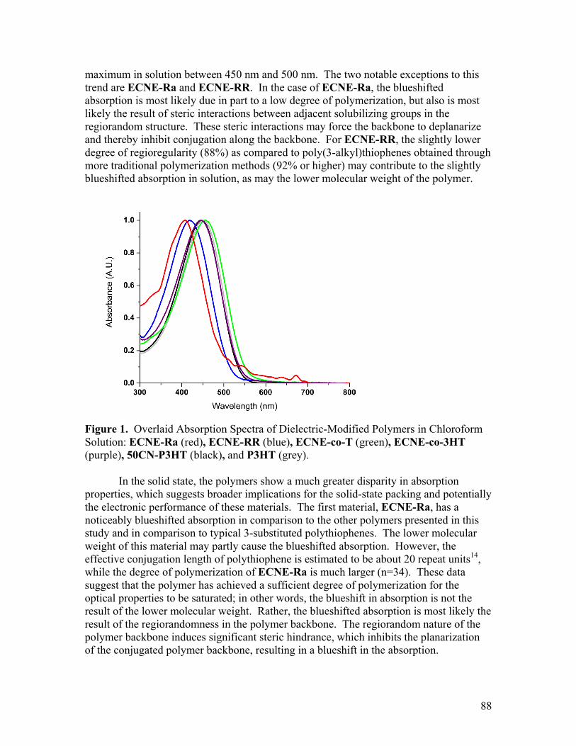
maximum in solution between 450 nm and 500 nm. The two notable exceptions to this trend are ECNE-Ra and ECNE-RR. In the case of ECNE-Ra, the blueshifted absorption is most likely due in part to a low degree of polymerization, but also is most likely the result of steric interactions between adjacent solubilizing groups in the regiorandom structure. These steric interactions may force the backbone to deplanarize and thereby inhibit conjugation along the backbone. For ECNE-RR, the slightly lower degree of regioregularity (88%) as compared to poly(3-alkyl)thiophenes obtained through more traditional polymerization methods (92% or higher) may contribute to the slightly blueshifted absorption in solution, as may the lower molecular weight of the polymer.
Figure 1. Overlaid Absorption Spectra of Dielectric-Modified Polymers in Chloroform Solution: ECNE-Ra (red), ECNE-RR (blue), ECNE-co-T (green), ECNE-co-3HT (purple), 50CN-P3HT (black), and P3HT (grey). In the solid state, the polymers show a much greater disparity in absorption properties, which suggests broader implications for the solid-state packing and potentially the electronic performance of these materials. The first material, ECNE-Ra, has a noticeably blueshifted absorption in comparison to the other polymers presented in this study and in comparison to typical 3-substituted polythiophenes. The lower molecular weight of this material may partly cause the blueshifted absorption. However, the effective conjugation length of polythiophene is estimated to be about 20 repeat units14, while the degree of polymerization of ECNE-Ra is much larger (n=34). These data suggest that the polymer has achieved a sufficient degree of polymerization for the optical properties to be saturated; in other words, the blueshift in absorption is not the result of the lower molecular weight. Rather, the blueshifted absorption is most likely the result of the regiorandomness in the polymer backbone. The regiorandom nature of the polymer backbone induces significant steric hindrance, which inhibits the planarization of the conjugated polymer backbone, resulting in a blueshift in the absorption.
88

When the structure of the polymer is changed from regiorandom to regioregular substitution of the solubilizing group, there is a marked redshift in the absorption of the polymer. ECNE-RR shows a considerable redshift in absorption in spite of a decrease in molecular weight and degree of polymerization. This considerable redshift indicates that the change in regiochemistry strongly enables planarization of the polymer backbone in the solid state. Further, ECNE-RR shows significant vibronic structure in a thin film, indicative of π−π stacking. The absorption spectrum of this polymer strongly resembles that of ECNE-co-T, the alternating copolymer between the ECNE-modified monomer and an unsubstituted thiophene. This similarity between the absorption spectra of ECNE-RR and ECNE-co-T suggests that copolymerizing an asymmetrically substituted thiophene with an unsubstituted thiophene is a viable means to offset the potential disruption in packing that can occur in a regiorandom polymer. Moreover, both of these materials show an absorption spectrum that is blueshifted relative to P3HT, indicating the potential for further improved π−π stacking in the solid state. Finally, regioregular copolymers were made that incorporate either an ECNE-modified thiophene or a cyanohexyl-modified thiophene copolymerized with a hexylthiophene. ECNE-co-3HT and 50CN-P3HT both show considerably redshifted absorption spectra relative to ECNE-Ra. Moreover, 50CN-P3HT shows a slight indication of vibronic structure in the solid state, and ECNE-co-3HT shows pronounced vibronic structure with a shoulder in the film UV-Vis at about 610 nm. These materials may be particularly attractive as they combine desirable optical properties with higher molecular weights that are expected to be advantageous for charge transport.
Figure 2. Overlaid Absorption Spectra of Dielectric-Modified Polymers in Thin Films: ECNE-Ra (red), ECNE-RR (blue), ECNE-co-T (green), ECNE-co-3HT (purple), 50CN-P3HT (black), and P3HT (grey). In addition to the optical properties, the oxidation potentials of the polymers were also studied in order to determine the effect of the modifying group on the electronic
89

properties and to determine the suitability of these materials for electronic applications. The optical band gaps as well as the HOMO and the estimated LUMO values are listed in Table 2. Based on these data, it is apparent that the ethylcyano ether and the cyanohexyl substitutents have a minimal impact on the electronic properties of the polymers. Table 2. Optical Band Gaps and Energy Levels of Polymers Polymer Eg opticala (eV) HOMOb (eV) LUMOc (eV) ECNE-Ra 2.4 5.6 3.2 ECNE-co-T 2.0 5.3 3.3 ECNE-RR 1.8 5.2 3.4 ECNE-co-3HT 2.0 5.2 3.2 50CN-P3HT 1.9 5.2 3.3 P3HT 1.9 5.2 3.3 aAs determined by the onset of absorption in the solid state bAs determined by the onset of oxidation in a thin film, calibrated to Fc/Fc+=-5.12 eV cestimated from LUMO=HOMO-Eg optical Dielectric Properties In order to establish the effect of highly polarizable functional groups on the dielectric constant of a conjugated polymer, the dielectric constants of the polymers were measured using impedance spectroscopy. The results of these measurements are shown in Figure 3. Further, the dielectric constants of these materials at 1000 Hz are listed Table 3 alongside those of other semiconducting materials previously reported in the literature.
1
6
11
16
21
1.00E+01 1.00E+02 1.00E+03 1.00E+04 1.00E+05 1.00E+06 1.00E+07
Die
lect
ric C
onst
ant
Frequency (Hz)
Figure 3. Dielectric Constants of Polymers Used in This Study: ECNE-Ra (red), ECNE-RR (blue), ECNE-co-T (green), and 50CN-P3HT (black). It is notable that all of the new conjugated materials presented here possess a higher dielectric constant as compared to the unmodified P3HT (ε=2.9). Further, the
90

dielectric constants of all of the materials presented here are higher than that of PC60BM, indicating that the ECNE group and the cyanohexyl group are both attractive routes to synthetically modifying the dielectric constant of an organic semiconductor. Studying the data further, a number of trends emerge. In all cases, the ECNE functional group is found to produce materials with higher dielectric constants as compared to the cyanohexyl modifying group. More specifically, ECNE-Ra has a dielectric constant of 20.7 at 1 kHz, making it markedly higher than any of the polymers studied here and higher even than single crystalline silicon. This tremendous increase in dielectric constant as compared to an unmodified polythiophene demonstrates the strong ability of the ECNE moiety to increase the dielectric constant of a conjugated material. While the increase in dielectric constant is strongly desirable, the blueshifted absorption of ECNE-RR is indicative of little long-range order in the polymer, which may ultimately be detrimental to the behavior of this material in electronic devices. When the regioregularity is increased substantially, as in ECNE-RR, the dielectric constant decreases slightly to 17.3. However, this slight decrease in dielectric constant still gives a considerably higher value than typically seen for conjugated polymers, and is concomitant with a considerable redshift in the absorption of the polymer. Therefore the slight decrease in dielectric constant may ultimately be offset by a considerable increase in absorption of visible light for the regioregular material. The extent of modification was also found to have a considerable impact on the dielectric constant. ECNE-co-T, which consists of the ECNE-containing monomer alternating with an unsubstituted thiophene, was shown to exhibit a dramatic decrease in dielectric constant, though this value (12.3) remains competitive with inorganic semiconductors. Finally, the nature of the modifying group is shown to be important, as 50CN-P3HT has a dielectric constant that is lower still (6.93) than that of ECNE-co-T, although it remains higher than that of unmodified P3HT or PC60BM. Table 3. Dielectric Constants of Semiconductors at 1000 Hz. Material ε at 1000 Hz ECNE-Ra 20.7 ECNE-RR 17.3 ECNE-co-T 12.3 50CN-P3HT 6.93 P3HT 2.9 PC60BM 4.41 Sia 11.714 asingle crystal Grazing Incidence X-Ray Diffraction Some of the polymers developed in this study were analyzed by grazing incidence x-ray diffraction (GIXS) in order to determine the extent to which they exhibit long-range order in the solid state. This property is expected to be important in determining charge transport mobility, another potentially critical parameter in determining the efficiency of
91

polythiophenes in photovoltaic devices. Scattering data for the polymers ECNE-RR, ECNE-co-T, 50CN-P3HT, and P3HT are shown in Figure 4. The relative intensities of the scattering in the qxy direction are also displayed in Figure 5. The polymer ECNE-co-T, which did not exhibit any evidence of vibronic structure or a significant redshift in UV-Vis spectra of films, also does not exhibit any evidence for crystallinity by GIXS analysis. ECNE-RR shows some evidence of long-range order, with a peak at 16.1 Å and a small peak at 3.79 Å. The peak at 3.79 Å corresponds to π−π stacking and is slightly closer than the 3.85 Å found for P3HT, which may be advantageous for charge transport. However, the relative intensities of the peaks around 3.8 Å and the peaks at 16.1 Å for ECNE-RR and 17.7 Å for P3HT are inverted relative to one another. The peaks between 16-17 Å are indicative of the interchain distance. The shorter interchain distance for ECNE-RR relative to P3HT suggests that the ECNE-substituted polymer is able to pack more closely than the hexyl-substituted polymer. The relative intensity of these peaks is also inverted for 50CN-P3HT relative to P3HT. In the case of 50CN-P3HT, the π−π stacking distance is the same as for P3HT, but the distance for interchain packing is 19.0 Å rather than 17.7 Å as for P3HT. This may indicate that the nitrile group at the end of the alkyl chains n 50CN-P3HT is acting to increase the spacing between the chains. The difference in relative intensity between the peaks indicates the orientation of the polymer chains relative to the substrate is orthogonal to that of P3HT. While P3HT orients with p-p stacking normal to the substrate, these polymers orient with p-p stacking parallel to the substrate, which may be highly advantageous for charge transport in the vertical direction. This may be related to the functional groups on the alkyl chains, but is most likely the result of lower molecular weights in these polymers; lower molecular weight polythiophenes have been shown to orient differently in a thin film relative to their higher molecular weight counterparts.
92
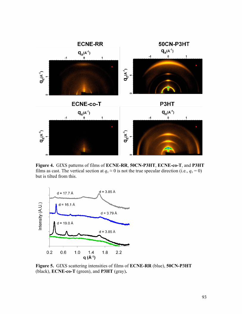
Figure 4. GIXS patterns of films of ECNE-RR, 50CN-P3HT, ECNE-co-T, and P3HT films as cast. The vertical section at qx ≈ 0 is not the true specular direction (i.e., qx = 0) but is tilted from this.
Figure 5. GIXS scattering intensities of films of ECNE-RR (blue), 50CN-P3HT (black), ECNE-co-T (green), and P3HT (gray).
93

Conclusions This work demonstrates the synthesis of conjugated polymers and oligomers with highly polarizable side chains, and that these functional groups produce a high dielectric constant in the resulting bulk materials. However, the crystallinity of these materials appears to be compromised relative to the unmodified P3HT. The changes in solid-state packing and long-range order can be seen in both the optical properties and in the XRD of polymer films. This decrease in solid-state packing is expected to negatively impact the electronic properties of these materials. Future development of conjugated polymers utilizing dielectric modifying groups should therefore focus on modifying polymers that do not rely on crystallinity for high charge mobility and light absorption. Some materials that may be particularly attractive in this regard are donor-acceptor conjugated polymers. Further, modifying the dielectric constant of the bulk film may be achievable by introducing small molecules or low molecular weight oligomers with high dielectric constants. The use of small molecule dopants may allow for an improved balance between high charge mobility of the polymer chains and high dielectric constants of the bulk films, though this may further complicate processing of these devices by requiring the use of a ternary blend in the active layer. Experimental Synthesis
All chemicals were purchased from commercial sources and used without further purification unless otherwise stated. 2,5-bis(trimethylstannyl)thiophene was prepared as described in the literature. Tetrahydrofuran (THF), N, N-dimethylformamide (DMF), and toluene were dried by passing through neutral alumina prior to use. All small molecules were characterized by 1H NMR (400 MHz) and 13C NMR (100 MHz) on a Bruker AVB 400 or AVQ 400. Polymer 1H NMR (500 MHz) spectra were obtained on a Bruker DRX 500. All NMR spectra were referenced to TMS. High-resolution mass spectroscopy and elemental analysis (CHN) were performed at the University of California, Berkeley Department of Chemistry analytical services laboratory. IR spectra were recorded on a Varian 3100 FT-IR as KBr pellets or as solid or liquid films drop-cast on KBr discs. Melting points are uncorrected. Column chromatography was performed with silica (230x400 mesh). Polymer molecular weights were determined by size exclusion chromatography (SEC) using THF as the mobile phase. SEC with THF mobile phase (1 mL/min, 45 °C) was carried out using a Waters GPC 150-CV plus system (Milford, MA) with an attached M486 tunable absorbance detector (254 nm), calibrated with polystyrene standards. The instrument was calibrated vs. polystyrene standards (1,050 – 135,000 g/mol) and data was analyzed using Millenium 3.2 software. 2-(2-bromothiophen-3-yl)ethan-1-ol (1): 2-(3-Thienyl)ethanol (10.0 g, 78 mmol, 1 eq) was dissolved in 400 mL tetrahydrofuran at 0 oC. While stirring at 0 oC, 1,3-Dibromo-5,5-dimethylhydantoin (11.15 g, 39 mmol, 0.5 eq)) was added in small portions over the course of 30 minutes. The reaction was allowed to warm to room temperature and stirred for an additional 2 hours. The reaction mixture was then poured over water and extracted
94
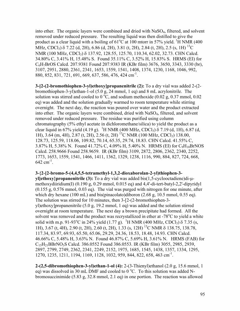
into ether. The organic layers were combined and dried with NaSO4, filtered, and solvent removed under reduced pressure. The resulting liquid was then distilled to give the product as a clear liquid with a boiling of 61oC at 100 mtorr in 57% yield. 1H NMR (400 MHz, CDCl3) δ 7.22 (d, 2H), 6.86 (d, 2H), 3.81 (t, 2H), 2.84 (t, 2H), 2.5 (s, 1H) 13C NMR (100 MHz, CDCl3) δ 137.92, 128.55, 125.70, 110.34, 62.02, 32.73. CHN Calcd. 34.80% C, 3.41% H, 15.48% S. Found 35.11% C, 3.52% H, 15.83% S. HRMS (EI) for C6H7BrOS Calcd. 207.9381 Found 207.9383 IR (KBr film) 3676, 3650, 3343, 3330 (br), 3107, 2951, 2880, 2361, 2341, 1653, 1559, 1541, 1408, 1374, 1230, 1168, 1046, 992, 880, 852, 831, 721, 691, 669, 637, 586, 476, 424 cm-1. 3-[2-(2-bromothiophen-3-yl)ethoxy]propanenitrile (2): To a dry vial was added 2-(2-bromothiophen-3-yl)ethan-1-ol (5.0 g, 24 mmol, 1 eq) and 8 mL acrylonitrile. The solution was stirred and cooled to 0 oC, and sodium methoxide (0.02 g, 0.37 mmol, 0.02 eq) was added and the solution gradually warmed to room temperature while stirring overnight. The next day, the reaction was poured over water and the product extracted into ether. The organic layers were combined, dried with NaSO4, filtered, and solvent removed under reduced pressure. The residue was purified using column chromatography (5% ethyl acetate in dichloromethane/silica) to yield the product as a clear liquid in 67% yield (4.19 g). 1H NMR (400 MHz, CDCl3) δ 7.19 (d, 1H), 6.87 (d, 1H), 3.64 (m, 4H), 2.87 (t, 2H), 2.56 (t, 2H) 13C NMR (100 MHz, CDCl3) 138.00, 128.73, 125.59, 118.06, 109.82, 70.14, 65.35, 29.74, 18.83. CHN Calcd. 41.55% C, 3.87% H, 5.38% N. Found 41.72% C, 4.09% H, 5.40% N. HRMS (EI) for C9H10BrNOS Calcd. 258.9666 Found 258.9659. IR (KBr film) 3109, 2872, 2806, 2362, 2340, 2252, 1773, 1653, 1559, 1541, 1466, 1411, 1362, 1329, 1238, 1116, 990, 884, 827, 724, 668, 642 cm-1. 3-2-[2-bromo-5-(4,4,5,5-tetramethyl-1,3,2-dioxaborolan-2-yl)thiophen-3-yl]ethoxypropanenitrile (3): To a dry vial was added bis(1,5-cyclooctadiene)di-μ-methoxydiiridium(I) (0.190 g, 0.29 mmol, 0.015 eq) and 4,4'-di-tert-butyl-2,2'-dipyridyl (0.155 g, 0.576 mmol, 0.03 eq). The vial was purged with nitrogen for one minute, after which dry hexane (100 mL) and bis(pinacolato)diboron (2.68 g, 10.5 mmol, 0.55 eq). The solution was stirred for 10 minutes, then 3-[2-(2-bromothiophen-3-yl)ethoxy]propanenitrile (5.0 g, 19.2 mmol, 1 eq) was added and the solution stirred overnight at room temperature. The next day a brown precipitate had formed. All the solvent was removed and the product was recrystallized in ether at -78oC to yield a white solid with m.p. 91-93oC in 24% yield (1.77 g). 1H NMR (400 MHz, CDCl3) δ 7.35 (s, 1H), 3.67 (t, 4H), 2.90 (t, 2H), 2.60 (t, 2H), 1.33 (s, 12H) 13C NMR δ 138.75, 138.78, 117.34, 83.97, 69.93, 65.50, 65.06, 29.29, 24.36, 18.53, 18.48, 14.93. CHN Calcd. 46.66% C, 5.48% H, 3.63% N. Found 46.87% C, 5.69% H, 3.61% N. HRMS (FAB) for C15H21BBrNO3S Calcd. 386.0552 Found 386.0553. IR (KBr film) 3055, 2985, 2939, 2897, 2799, 2749, 2362, 2341, 2249, 2152, 1975, 1685, 1545, 1438, 1357, 1334, 1295, 1270, 1235, 1211, 1194, 1169, 1128, 1032, 959, 844, 822, 658, 463 cm-1. 2-(2,5-dibromothiophen-3-yl)ethan-1-ol (4): 2-(3-Thienyl)ethanol (2.0 g, 15.6 mmol, 1 eq) was dissolved in 30 mL DMF and cooled to 0 oC. To this solution was added N-bromosuccinimide (5.83 g, 32.8 mmol, 2.1 eq) in one portion. The reaction was allowed
95

to warm slowly to room temperature over the course of two hours, at which point it was poured over ice water and the product extracted into ether. The combined organic layers were then washed three times with water, dried with NaSO4, filtered, and solvent removed under reduced pressure to yield a pale yellow oil. This oil was applied to a column (20% ethyl acetate in dichloromethane/silica) and purified to yield 3.89 g of the product in 87% yield. 1H NMR (400 MHz, CDCl3) δ 6.88 (s, 1H), 3.82 (m, 2H), 2.82 (t, 2H), 1.49 (1H) 13C NMR (100 MHz, CDCl3) δ 139.09, 131.25, 110.85, 109.44, 61.84, 32.75. CHN Calcd. 25.2% C, 2.11% H. Found 25.59% C, 2.07% H. HRMS (EI) for C6H6Br2OS 283.8506 Found 283.8503. IR (KBr film) 3588, 3341, 3317 (br), 2952, 2878, 2362, 1718, 1647, 1542, 1473, 1419, 1356, 1245, 1196, 1162, 1047, 1002, 960, 927, 892, 824, 653 cm-1. 3-[2-(2,5-dibromothiophen-3-yl)ethoxy]propanenitrile (5): 2-(2,5-dibromothiophen-3-yl)ethan-1-ol (2.43 g, 8.5 mmol, 1 eq) and acrylonitrile (6 mL) were stirred and cooled to 0 oC in a dry vial. Then, sodium methoxide (0.014 g,, 0.25 mmol, 0.03 eq) was added and the solution allowed to gradually warm to room temperature. The following day the reaction was poured over water and extracted with ether. The organic layers were combined and dried with MgSO4, then filtered and the solvent removed to yield an oily product. The reaction mixture was purified on silica using 5% ethyl acetate in dichloromethane as the eluent to recover the product as a clear oil in 80% yield. 1H NMR (400 MHz, CDCl3) δ 6.88 (s, 1H), 3.65 (m, 4H), 2.81 (d, 2H), 2.60 (t, 2H) 13C NMR (100 MHz, CDCl3) δ 138.97, 131.38, 117.78, 110.66, 109.21, 70.02, 65.43, 29.80, 18.87. CHN Calcd. 31.88% C, 2.68% H, 4.13% N. Found 32.14% C, 2.74% H, 4.14% N. HRMS (EI) for C9H9Br2NOS Calcd. 336.8781 Found 336.8772. IR (KBr film) 3095, 2873, 2802, 2745, 2362, 2252, 1919, 1653, 1542, 1483, 1419, 1366, 1328, 1259, 1224, 1177, 1121, 1050, 1003, 983, 927, 829, 687, 655, 585, 474 cm-1. 3-(6-bromohexyl) thiophene (6): 3-bromothiophene (10.2 g, 0.0626 mol) was dissolved in dried hexane (80 mL), and the solution was cooled to -78ºC. 25 mL of 2.5M n-BuLi hexane solution was then added dropwise, and the solution was stirred at this temperature for 10 minutes. Dry THF (7 mL) was then added dropwise until the white 3-lithiothiophene salt precipitated. The solution was then stirred for 1 hour, and then allowed to warm to -10ºC. Dry THF (3 ml) and 1,6-dibromohexane (37ml, 0.24 mol) were then added to the solution. The solution was stirred at room temperature for 2 hours, and then washed with water (3×300ml). The organic layer was dried over anhydrous MgSO4, filtered and concentrated. Distillation at 60ºC at 0.18 mbar gave the product as a colorless liquid (4.33g, 28.0% yield). 1H NMR (500 MHz, CDCl3) δ 7.22(d, 1H), 6.90(d, 2H), 3.39(t, 2H), 2.62(t, 2H), 1.84(m, 2H), 1.62(m, 2H), 1.44(m, 2H), 1.35(m, 2H) 13C NMR (125 MHz, CDCl3) δ 142.74, 128.10, 125.07, 119.81, 33.89, 32.61, 30.22, 30.01, 28.28, 27.87. HRMS (EI) for C10H15BrS Calcd 248.0057; Found 248.0054. 2-bromo-3-(6-bromohexyl) thiophene (7): 3-(6-bromohexyl) thiophene (4.33 g, 0.0175 mol) was dissolved in dry THF (60ml). The solution was cooled in an ice bath, and 1,3-dibromo-5,5’-dimethylhydantion (2.63 g, 0.00919 mol) was added and the mixture was stirred at room temperature for 2 hours. After concentrating the mixture under reduced pressure dry hexane was added, and the mixture was filtered, and concentrated. Further
96

purification was carried out via silica gel column chromatography, using hexane as the eluent. The resulting product was dried under vacuum at 100 mtorr overnight to yield 2-bromo-3-(6-bromohexyl) thiophene as a clear oil (4.33g, 72% yield). 1H-NMR (500 MHz, CDCl3) δ 7.18(d, 1H), 6.78(d, 1H), 3.39(t, 2H), 2.55(t, 2H), 1.86(m, 2H), 1.58(m, 2H), 1.46(m, 2H), 1.35(m, 2H). 13C NMR (125 MHz, CDCl3,) δ 141.54, 128.12, 125.24, 108.90, 33.91, 32.65, 29.46, 29.16, 28.21, 27.88. HRMS (EI) for C10H14Br2S Calcd 325.9162; Found 325.9168. CHS anal. calcd for C10H14Br2S: C 36.83, H 4.33, S 9.83. Found: C 36.62, H 4.26, S 9.44. ECNE-Ra: In a dry, three-neck round bottom flask, 5 (1 eq, 1.171 mmol, 0.397 g) was dissolved in a mixture of 23 mL toluene and 7 mL DMF. Hexamethylditin (1 eq, 1.171 mmol, 0.382 g) was added and the solution degassed by purging with nitrogen for 20 minutes. After degassing, Pd(PPh3)4 (0.10 eq, 0.12 mmol, 0.13 g) was added and the reaction mixture heated to 105oC overnight. The following day the reaction mixture was cooled to room temperature and poured over methanol to yield the crude polymer as an orange-red solid. The polymer was purified by Soxhlet extraction with methanol, hexanes, and chloroform. The chloroform fraction was concentrated to yield the polymer as a reddish-orange solid in 48% yield. 1H NMR (500 MHz, CDCl3) δ 7.0-7.2 (br m, 1H) 3.6-3.9 (m, 4H), 3.1 (s, 1H), 3.9 (s, 1H), 2.6 (s, 2H). SEC (THF) Mn 6 kDa, Mw 10 kDa, PDI 1.6. IR (NaCl disc) 3663, 3584, 2962, 2922, 2872, 2250, 1660, 1548, 1468, 1413, 1365, 1329, 1261, 1225, 1112, 1020, 797 cm-1. ECNE-co-T: In a dry three-neck round bottom flask, 5 (1 eq, 0.59 mmol, 0.200 g) and 2,5-bis(trimethylstannyl)thiophene (1 eq, 0.59 mmol, 0.242 g) were dissolved in 30 mL THF. The solution was degassed by purging with nitrogen for 20 minutes, then CsF (4 eq, 2.36 mmol) and Pd(PtBu3)2 (0.05 eq, 0.03 mmol, 0.015 g) were added under strong nitrogen pressure. The reaction was then heated to 40oC and allowed to stir overnight. The following day the reaction was cooled to room temperature and precipitated into methanol. The polymer was collected by filtration and purified by Soxhlet extraction with methanol, cyclohexane, ethyl acetate, and chloroform. The chloroform fraction was recovered and reprecipitated into methanol to give the product as a red-purple solid in 45% yield (70 mg). 1H NMR (500 MHz, CDCl3) δ 7.12 (br, 3H), 3.78 (m, 4H), 3.13 (br, 2H), 2.67 (m, 2H) CHN Calcd for C13H11NOS2 59.74% C, 4.24% H, 5.36% N, found 56.89% C, 4.37% H, 4.72% N. SEC (THF) Mn 3.1 kDa, Mw 5 kDa, PDI 1.7. IR 3065, 2962, 2924, 2871, 2252, 1498, 1417, 1361, 1260, 1224, 1112, 1022, 871, 797 cm-1. ECNE-co-3HT: 3 (1 eq, 0.256 mmol, 0.099 g) and 2-(5-bromo-4-n-hexyl-thiophen-2-yl)-4,4,5,5-tetramethyl-[1,3,2]dioxaborolane (1.84 eq, 0.477 mmol, 0.178 g) were dissolved in THF (20 mL). In a separate flask, CsF (4 eq, 2 mmol, 0.315 g) was dissolved in water (2mL). The two solutions were combined and degassed by purging with nitrogen for 20 minutes. After degassing, Pd2(dba)3 (0.05 eq, 0.026 mmol, 0.026 g) and Pd(PtBu3)2 (0.1 eq, 0.052 mmol, 0.026 g) were added in single portions to the reaction mixture under strong nitrogen pressure. The reaction was then stirred at room temperature overnight. The following day the reaction was poured over methanol to precipitate the crude polymer. The recovered solid was then purified by Soxhlet extraction with methanol and then chloroform. The chloroform fraction was concentrated
97
and reprecipitated into methanol to yield a purple solid, which was then washed by Soxhlet extraction with hexanes. The material was recovered from the Soxhlet thimble to yield 97 mg of a purple solid (77% yield). 1H NMR δ 7.05 (m, ArH), 3.83 (s), 3.78 (m), 3.16 (t), 2.84 (t), 2.66 (t), 1.89 (t), 1.74 (t), 1.47 (m), 1.38 (m), 0.95 (m). SEC (THF) Mn 9.6 kDa, Mw 17.6 kDa, PDI 1.8 IR (NaCl film) 2956, 2926, 2855, 2362, 2335, 2253, 1636, 1508, 1457, 1261, 1113, 1021, 801 cm-1. ECNE-RR: In a three-neck flask, 3 (1 eq, 0.388 mmol, 0.15 g), was dissolved in 40 mL THF. In a separate container, CsF (4 eq, 1.552 mmol, 0.236 g) was dissolved in 4 mL water. The solutions were combined and degassed by purging with nitrogen for 20 minutes. Once the solution was degassed, Pd(PtBu3)2 (0.1 eq, 0.038 mmol, 0.019 g) and Pd2(dba)3 (0.05 eq, 0.019 mmol, 0.018 g) were added separately in single portions, and the reaction was stirred at room temperature overnight. The following day, the reaction was poured over methanol to yield a purple solid. The crude polymer was further purified by Soxhlet extraction into THF to yield 32 mg of polymer as a red solid (46%). 1H NMR (500 MHz, CDCl3) δ 7.08 (s, 1H), 3.81 (m, 2H), 3.71 (m, 2H), 3.13 (m, 2H), 2.64 (m, 2H) SEC (THF) Mn 4 kDa, Mw 5 kDa, PDI 1.3 IR (NaCl film) 2918, 2850, 2362, 2340, 1260, 1107, 1022, 800, 668 cm-1. 50Br-P3HT: Lithium diisopropylamide (LDA) was generated by addition of n-BuLi (2.5M in hexane, 3.0 mL, 7.50 mmol) to a solution of dry diisopropylamine (1.35 mL, 9.55mmol) in dry THF (18 mL) at -78ºC. The solution was stirred at this temperature for 1 hour. The freshly generated LDA solution was added dropwise to the mixture of 2-bromo-3-(6-bromohexyl)thiophene (1.31 g, 4.02 mmol) and 2-bromo-3-hexylthiophene (0.99 g, 4.02 mmol) in dry THF (75ml) at -78 ºC. After one hour reaction at -78ºC, anhydrous ZnCl2 (1.29 g, 9.64 mmol) was added portionwise to the mixture, which was stirred for 30mins and then warmed slowly to room temperature. Polymerization initiated by addition of Ni(dppp)Cl2 (0.0525 g, 0.97 mmol) to the mixture was carried out at room temperature for 45 minutes. The solution was quenched by 1.5mL of 1.0N aqueous HCl in order to stop the polymerization. The polymer was precipitated with MeOH (450 mL) containing 4.5 mL of NH3 7N in MeOH solution to neutralize it, and the resulting precipitate was then filtered. Oligomers and impurities in the product were removed by Soxhlet extractions with MeOH for > 3 hours, followed by hexane extraction for > 5 hours. The resulting solid was dried under vacuum to yield the product in 70% yield. 1H NMR (500 MHz, CDCl3) δ 6.96(s, ArH), 3.40(t, Br-CH2), 2.78(t, Ar-CH2), 1.87(br m, BrCH2-CH2), 1.69(br m, CH3CH2-CH2), 1.2-1.5(br m, CH2) , 0.89(s, CH3) SEC (THF) Mn 20 kDa, Mw 31 kDa, PDI 1.2.
50CN-P3HT: 50% Br-copolymer (0.120 g, 0.29 mmol, 1 eq) was dissolved in a mixture of dry THF (24 mL) and dry DMF (7 mL). To this solution was added KCN (0.189 g, 2.9 mmol, 10 eq) and 18-crown-6 (0.766 g, 2.9 mmol, 10 eq). The solution was degassed by purging with nitrogen for 20 minutes, then the solution was heated to 65 oC overnight. The next day the reaction was cooled to room temperature, and the polymer precipitated into methanol. The polymer was collected by filtration, subjected to Soxhlet extraction in methanol overnight, then dried under vacuum overnight to yield 97 mg of product (92 % yield). 1H NMR (500 MHz, CDCl3) δ 6.98 (d, ArH), 2.82 (t, Ar-CH2), 2.35 (t, CN-CH2),
98

1.7 (br m), 1.5-1.3 (br m), 0.91 (t, CH3). SEC (THF) Mn 20 kDa, Mw 31 kDa, PDI 1.2. IR (NaCl film) 3105, 3055, 2929, 2857, 2247, 1558, 1509, 1464, 1457, 1377, 1337, 1149, 1084, 904, 866, 821, 714 cm-1. Dielectric Constant Measurements The dielectric constant of a polymer film was determined by impedance spectroscopy. Diode-like devices were fabricated with the structure ITO/ PEDOT:PSS/ polymer/ Al. The complex impedance of the device was measured using a Solartron SI 1260 impedance analyzer by applying an oscillating voltage of 100 mV. The measurement was performed in the dark at ambient conditions at a range of frequencies from 10 MHz to 10 Hz. The equivalent circuit in Figure S2 was used, with a capacitance C, a parallel resistance Rp, a series resistance Rs to model the data. The capacitance (C) was used to calculate the dielectric constant of the polymer film by:
A
Cd
0εε = (1)
where d is the thickness of the film, ε0 is the permittivity of free space, and A is the area of the electrode. Thicknesses of polymer films were ~ 60-70 nm, and the electrode area was 1cm2. Grazing Incidence X-ray Diffraction Grazing-Incidence X-ray Scattering (GIXS) experiments were conducted at the Stanford Synchrotron Radiation Laboratory on beamline 11-3. The sample was irradiated at a fixed incident angle on the order of 0.1o and the GIXS patterns were recorded with a 2-D image detector (MAR345 image plate detector). GIXS patterns were recorded with an X-ray energy of 12.72 keV (λ = 0.975 Å). To maximize the intensity from polymer sample, the incident angle (~0.1°-0.12°) was carefully chosen so that the X-ray beam penetrates the polymer sample completely but not the silicon substrate. Typical exposure times were 90-180 s. To produce identical surface condition as samples for device fabrication, a thin layer (20-30 nm) of PEDOT:PSS was spun onto silicon substrates with a native oxide. Then the GIXS samples were prepared by spin-coating the same polymer solutions used for making devices onto silicon substrates. References 1. Hebard, A. F.; Haddon, R. C.; Fleming, R. M.; Kortan, A. R. Appl. Phys. Lett. 1991, 59, 2109-2111. 2. Opris, D. M.; Nüesch, F.; Löwe, C.; Molberg, M.; Nagel, M. Chem. Mater. 2008, 20, 6889-6896. 3. Nalwa, H.; Dalton, L.; Vasudevan, P. European Polymer Journal 1985, 21, 943- 947. 4. Yen, S.; Lewis, Carol R.; Cygan, Peter J.; Jow, Richard T. Cyanoresin, cyanoresin/cellulose triacetate blends for thin film, dielectric capacitors - Patent 5490035.
99

100
5. Murase, Ichiki; Fujita, Fumio; Ohnishi, Toshihiro; Tamura, Toshifumi Highly dielectric polysaccharides. 6. Osaka, I.; McCullough, R. D. Acc. Chem. Res. 2008, 41, 1202-1214. 7. Ishiyama, T.; Takagi, J.; Ishida, K.; Miyaura, N.; Anastasi, N. R.; Hartwig, J. F. J. Am. Chem. Soc. 2002, 124, 390-391. 8. Kim, Y.; Cook, S.; Tuladhar, S. M.; Choulis, S. A.; Nelson, J.; Durrant, J. R.; Bradley, D. D. C.; Giles, M.; McCulloch, I.; Ha, C.; Ree, M. Nat. Mater. 2006, 5, 197-203. 9. McCullogh, R. D.; Williams, S. P.; Tristam-Nagle, S.; Jayaraman, M.; Ewbank, P. C.; Miller, L. Synth. Met. 1995, 69, 279-282. 10. Woo, C. H.; Thompson, B. C.; Kim, B. J.; Toney, M. F.; Fréchet, J. M. J. J. Am. Chem. Soc. 2008, 130, 16324-16329. 11. Sivula, K.; Luscombe, C. K.; Thompson, B. C.; Fréchet, J. M. J. J. Am. Chem. Soc. 2006, 128, 13988-13989. 12. Thompson, B. C.; Kim, B. J.; Kavulak, D. F.; Sivula, K.; Mauldin, C.; Fréchet, J. M. J. Macromolecules 2007, 40, 7425-7428. 13. Ma, J.; Li, S.; Jiang, Y. Macromolecules 2002, 35, 1109-1115. 14. Dunlap, W.C.; Watters, R.L. Phys. Rev. 1953, 92, 1396-1397.