Embed Size (px)
Citation preview

1Symmetry Elements
and Operations
1.1 Introduction
Symmetry and group theory provide us with a formal method for the description of thegeometry of objects by describing the patterns in their structure. In chemistry, it is a pow-erful method that underlies many apparently disparate phenomena. Symmetry allows usto describe accurately the types of bonding that can occur between atoms or groups ofatoms in molecules. It also governs the transitions that may occur between energy lev-els in molecular systems, which in turn allows us to predict the absorption properties ofmolecules and, hence, their spectra.
This book will lay out the formal language used in the area, using illustrative exam-ples of particular molecules throughout. We will then apply the ideas of symmetry todescribe molecular structure and bonding in molecules and to consider the implications inspectroscopy.
Even in our surroundings we often look for symmetry, Figure 1.1 shows a picture ofa wood engraving entitled Fish, Vignette made in 1955 by the artist M.C. Escher. In thiswork, the intertwined fish are shown set inside a hexagonal border. All of the fish illustratedhave the same shape and they are designed to fit together perfectly. Six of the fish touchfins in the centre of the image and each of these has a partner with a fin on a corner ofthe hexagon. If we imagine rotating the picture by 60◦ about the central point, each fishwould move to a new position and exactly replace a fish of opposite colour. This propertygives the picture an attractive quality, but it also tells us that we could reconstruct thewhole image by knowing the shape of the fish and the initial position of any pair, simplyusing six equivalent sections placed according to the rotation. At each step all we needdo is remember to change the colours of the fish. The image is said to have rotationalsymmetry, and the techniques of this book provide a concise method of stating the rulesfor the construction of the picture.
Molecular Symmetry David J. Willockc© 2009 John Wiley & Sons, Ltd
COPYRIG
HTED M
ATERIAL

2 Molecular Symmetry
Figure 1.1 M.C. Escher’s ‘Fish, Vignette’ Copyright 2008 The M.C. Escher Company-Holland. All rights reserved. www.mcescher.com.
Figure 1.2 shows the ceiling of the Arab Room of Cardiff Castle. It is clear that the dec-orators have gone to a lot of trouble to use symmetry. In this case, a rotation of the imagethrough 90◦ would interchange the positions of the windows; but, since they are identical,the pattern would appear unchanged. Four such rotations are possible, with the last return-ing each part of the ceiling to exactly its initial location. This image also has additionalsymmetry properties not possessed by Escher’s fish. Imagine a line drawn horizontallyacross the image so that it passes through the centre of the left- and right-hand windows.The two sections of the image are now reflections of each other, with each feature in theupper part of the picture repeated in the lower half, as if reflected in a mirror standing

Symmetry Elements and Operations 3
Figure 1.2 Arab Room ceiling, Cardiff Castle. Copyright: Cardiff Council.
perpendicular to the line. The mirror can be thought of as a plane of symmetry, and thisimage contains four such planes.
We can also look for planes of symmetry in nature. The fern frond shown in Figure 1.3looks perfectly normal at first glance. However, on close inspection it can be seen that theleft side of the leaf is just a reflection of the right-hand side on the surface of a pond. Thepicture is shown with the water surface vertical, which enhances the illusion. From halfthe leaf and its reflected image we can easily imagine the complete structure.
In chemistry, symmetry is not simply to do with beauty. It affects the properties ofmolecules and, in particular, influences the spectra we observe. For instance, most peoplewould say that benzene is a ‘more’ symmetric molecule than fluorobenzene (Figure 1.4),since the fluorinated carbon should be different to the other carbon atoms. Figure 1.5 showsthat this simple substitution has a profound affect on the infrared (IR) spectra of the twomolecules.
The IR spectrum of benzene is very simple, showing only four main bands. On substitu-tion with a single fluorine atom to give fluorobenzene, the spectrum becomes much morecomplex, with many more bands appearing between 400 and 1600 cm−1.
We know that IR spectra are the result of radiation exciting vibrational modes in amolecule. The number of possible lines is related to the number of vibrational modes forthe molecule in question. Since each atom in a molecule can move in three dimensions(X, Y, Z), both benzene and fluorobenzene will have a total of 36 degrees of freedom. For

4 Molecular Symmetry
Figure 1.3 The frond of a fern imaged at the surface of a pond. Although we see a completeleaf, the left-hand side is actually a reflection. In fact, the segments (or pinna) on oppositesides of a frond are usually not quite mirror images of one another, as the points at which thepinna attach to the stem are staggered.
(a) (b)
F
Figure 1.4 The structures of (a) benzene and (b) fluorobenzene.

Symmetry Elements and Operations 5
0.1
1
10
100
5001000150020002500300035004000
0.1
1
10
100
5001000150020002500300035004000
(a)
(b)
1 2
3
4
F
Transmittance / %
Transmittance / %
Wavenumber / cm–1
Wavenumber / cm–1
Figure 1.5 The infra-red spectra of (a) benzene and (b) fluorobenzene. Note that thetransmittance scale is logarithmic and the drop in the base line between around 700 and500 cm−1 is a feature of the instrument. Data kindly provided by Dr Mike Coogan, School ofChemistry, Cardiff University.
a nonlinear molecule there are six degrees of freedom associated with the motion of themolecule as a whole (three translations and three rotations), and these are not vibrations.So, we expect the number of vibrational modes for a molecule containing N atoms to be3N−6. Both benzene and fluorobenzene have 12 atoms, and so have 30 vibrational modes.The fact that this does not result in 30 IR absorptions is a result of the symmetry of themolecules; and because benzene is ‘more’ symmetric than fluorobenzene, fewer modes ofvibration are detected in the spectrum of benzene than in that of fluorobenzene.
To understand and quantify these differences in spectra we need more rigorous defini-tions of symmetry than simply saying benzene is ‘more’ symmetric than fluorobenzene.The geometric constructs of molecular symmetry help us to define a molecule’s symmetryand the use of group theory allows us to predict the number of absorption lines that willbe observed.
To achieve this we look for features in the geometry of a molecule that give rise toits symmetry. The most easily recognized of these features, or symmetry elements, arerotational axes (lines of symmetry) and mirror planes (planes of symmetry). These willbe discussed in the remaining sections of this chapter, along with the inversion centre,which is a point of symmetry. There are other symmetry elements and operations thatare possible, and we will meet these in Chapter 2. The symmetry elements imply that

6 Molecular Symmetry
there are symmetry operations: actions that can be carried out which appear to leave themolecule unchanged. If a molecule has multiple symmetry elements then there will be atleast one point in space which lies within them all. For example, Figure 1.8 shows that allthe rotation axes of ferrocene meet at the central point where the Fe atom is located. Forthis reason, the symmetry of molecules is often referred to as point group symmetry. Theidea of this book is to introduce the ideas of point group symmetry and its application invibrational spectroscopy and the molecular orbital (MO) description of chemical bonding.
In periodic systems (such as crystal structures), other symmetries exist to do with trans-lation between equivalent molecules. See the Further Reading section at the end of thischapter for a book on this topic.
1.2 Symmetry Elements and Operations
1.2.1 Proper Rotations: Cn
The geometric properties of shapes that make them symmetric can be classified by theirsymmetry elements. The validity of a symmetry element can be checked by carrying outthe corresponding operation and then comparing the object with the starting point. Forexample, imagine constructing an axis for a water molecule which runs through the oxygenatom, bisecting the H O H angle, with the axis in the plane of the molecule. This con-struction is shown in Figure 1.6, which also illustrates the result of rotating the moleculeby 180◦ around the axis. After the rotation, we end up with a view of the water moleculeidentical to the starting point, so much so that if we had not labelled the hydrogen atomsit would be indistinguishable from the original. This result shows that the axis we havedrawn is a symmetry element of the molecule and the act of rotating the molecule is thecorresponding symmetry operation. The rotation operation also shows that the two hydro-gen atoms in the water molecule are equivalent; if a symmetry operation can interchangetwo atoms, then the atoms must occupy identical chemical environments.
C2 element
C2 operation
H1H2 H2
H1
O O
Figure 1.6 The C2 symmetry element of water and the result of the C2 operation.
Rotational elements and operations are labelled using a capital C. For rotations by 180◦
there are two positions of the molecule which appear identical, the starting point and themolecule after the rotation, so a subscript 2 is added to the label: C2. This subscript isknown as the order of the rotation axis.
To emphasize the difference between elements and operations further, consider thestructure of ammonia shown in Figure 1.7. A C3 axis is present: the symmetry elementis a line running through the nitrogen atom and the centre of the triangle formed by thethree hydrogen atoms.

Symmetry Elements and Operations 7
C3 element C3 operations
N
H1H2
H3
N
H2H3
H1N
H3H1
H2C3
1
C31
C32
Figure 1.7 The C3 axis of ammonia and the corresponding operations. The lower imageshows a ball-and-stick model of ammonia in roughly the same orientation as the chemicaldrawing pictures above. The superscript on the operations gives the number of rotationsstarting from the initial configuration.
The C3 axis actually has two symmetry operations associated with it, as can be seen inFigure 1.7: a rotation by 120◦ and a rotation by 240◦. By convention, a rotation operationmoves the atoms clockwise when looking down the axis direction. In the first step of theoperation sequence shown in Figure 1.7, a clockwise rotation by 120◦ takes each hydrogenatom to the position of one of its neighbours. A second application of the operation takeseach hydrogen atom to the original position of its other neighbour. To distinguish the twooperations we add a superscript to indicate how many times the operation has been applied.So C3
2 means that, starting from the original configuration, two successive rotations of120◦ are applied, i.e. a total of 240◦.
Molecules may contain more than one rotation axis, and those axes may have differentorders. In this situation, the highest order axis is termed the principal axis. As an example,Figure 1.8 shows the structure of ferrocene (di-cyclopentadienyl iron(II)). This complexhas a C5 axis, which is the line joining the centres of the cyclopentadiene rings throughthe Fe centre (Figure 1.8a). In addition, there are five C2 axes that run through the Featom parallel to the ring systems and perpendicular to the principal axis. These are bestseen looking down the principal axis direction, as shown in Figure 1.8b. The C2 rotationoperations cause the exchange of the cyclopentadiene rings, whereas the C5 operationsimply rotates each cyclopentadiene ring around its centre. There is a convention thatmolecules are orientated so that the principal axis defines the vertical direction and thatthis is also aligned with the Cartesian Z-axis. This means that the vertical direction inFigure 1.8a runs up the page, whereas ‘vertical’ in Figure 1.8b is into the page.
The symmetry elements for a molecule are fixed in space: as we move the atoms undera given operation the symmetry elements are not shifted. For ferrocene, the atoms of thecomplex can be moved between any of five arrangements using the principal axis. In any

8 Molecular Symmetry
(a) (b)
Fe
C2
C5
C2
C2
C2
C2
C2
FeFe
Figure 1.8 The structure of ferrocene, illustrating (a) the C5 axis and an example C2 axis;(b) a plan view of the molecule showing all five C2 axes.
of these, each of the C2 axes remains a symmetry element. The five C2 axes meet at a pointon the principal axis and they have an angular spacing of 72◦, i.e. the angle of rotation forthe C5
1 operation. So, after a C51 operation, the arrangement of the atoms around any of
the C2 axes is shifted to one of its neighbours; this implies that all the C2 axes have anequivalent environment of atoms, and so they are treated as equivalent axes.
It is also possible for a molecule to contain axes of the same order that are not equivalentto one another. Figure 1.9 shows the structure of benzene, a molecule which has a C6 prin-cipal axis perpendicular to the molecular plane. Each of the carbon atoms in benzene canbe placed at any of the six positions by successive applications of the C6 rotation and so allof the carbon atoms are in identical environments. Each C6 operation rotates the moleculeabout its centre by 60◦. Two C6 operations, C6
2, will give a rotation of 120◦, which we havealready seen corresponds to a C3
1 rotation. We will usually use the lowest order alternativewhen listing symmetry operations, so that the C6 axis has associated with it:
C61, which is unique
C62 = C3
1
C63 = C2
C64 = C3
2
C65, which is unique.
This means that the C6 axis gives rise to two C6 operations, two C3 operations and a C2
operation, and so there must always be C3 and C2 axes collinear with a C6.In the plane of the benzene molecule there are also C2 axes that pass through opposite
carbon atoms. The rotations about these axes must not be confused with the C2 operationfrom the principal axis, and so the axes are labelled C2
′, as shown in Figure 1.9. The C2′

Symmetry Elements and Operations 9
C2″
C2″
C2″
C2′C2′
C2′
Figure 1.9 The structure of benzene showing the two sets of three C2 axes in the molecularplane; the principal C6 axis is perpendicular to the plane and passes through the centre of themolecule at the crossing point of the C ′
2 and C ′′2 axes.
axes are 60◦ apart, and so successive C6 operations will alter which particular atoms are onwhich C2
′ axes. However, each C2′ axis always contains two C and two H atoms, and so the
three axes are equivalent. There is a second set of axes which join opposite bond centres,and these are labelled C2
′′ to distinguish them from the C2′ axes. We can tell that the C2
′′
and C2′ axes form distinct sets both from their chemical environments (one set join bond
centres and one set join atoms) and from the fact that the C6 operations never interchange abond centre and an atom position. We have made the choice that the axes joining oppositeatoms should be labelled C2
′ and that those between the bond centres that do not containany atoms in the symmetry element are labelled C2
′′.A further possibility for multiple rotation axes is to have more than one candidate for the
principal axis. For example, the highest order axis for ethene is a twofold axis, but thereare three nonequivalent C2 axes, as shown in Figure 1.10. The choice of principal axis isnow arbitrary, and it is usual to assign each axis a Cartesian label (X,Y or Z) so that theycan be referred to explicitly.
1.2.2 The Plane of Symmetry: σ
If a plane exists for which reflection of each atom in a molecule gives an indistinguishableconfiguration, the molecule is said to have a plane of symmetry, which is given the label σ .

10 Molecular Symmetry
H
H
H
H
C2(Y )
C2(X )C2(Z )
Figure 1.10 The structure of ethene showing three distinct C2 axes.
The symmetry element is the plane itself, since all points in the plane remain unchangedby the operation of reflection. For the water molecule there are two planes of symmetry, asshown in Figure 1.11. These are distinguished by labelling the plane perpendicular to themolecule σ and the plane of the molecule itself σ ′. The C2 axis of water is the only axis,and so it is also the principal axis defining the vertical direction. This means that the mirrorplanes are standing vertically, and so a subscript is added to remind us of this, giving σv
and σv′.
Element σv
Element σv′
Operation σv′
Operation σv
H1
OH2
H2
H2H1
H1
O
O
Z
Y
X
σv(XZ )
σv′(YZ )
Figure 1.11 The two mirror planes for the H2O molecule showing the difference between σv
and σv′ operations. The inset shows the relationship between the mirror planes and a reference
axis system.
Which plane is which is a somewhat arbitrary choice; however, the designationdescribed here is quite widely used and is based on the alignment of the symmetry planeswith the Cartesian axis system. Figure 1.11 shows that the two planes intersect in the lineof the C2 axis we identified earlier; the planes of symmetry are said to contain the rota-tional axis. The principal axis gives us the Cartesian Z-direction, which, in this case, is in

Symmetry Elements and Operations 11
the molecular plane. We also take Y to be in the molecular plane, and so X must be per-pendicular to it. The full labels for the mirror planes of water become σv(XZ) and σv
′(YZ),but it is common to omit the Cartesian parts of these labels.
Some molecules have multiple axes and mirror planes. For example, boron trifluoride(BF3) is a planar molecule with a C3 axis perpendicular to the plane and passing throughthe boron atom, as shown in Figure 1.12. However, there are also C2 axes in the plane ofthe molecule which run along each of the B F bonds.
F3B
F2
F1
F3B
F2
F1
F3B
F2
F1
C3
C2
BF1
F2 F3
C2
C2
Figure 1.12 The rotational symmetry elements of BF3. To the left is a flying wedge drawinglooking from the side of the molecule in the same orientation as the perspective ball-and-stick model below it. The C2 axes are shown with the molecule viewed looking down on themolecular plane.
The highest order axis present is taken to be the principal axis and gives us the ‘vertical’direction. So, BF3 has three vertical mirror planes, each of which contains a B F bond; anexample of a vertical mirror plane in BF3 is shown in Figure 1.13a. The C3 operations willmove the fluorine atoms between these planes, but each will always contain one fluorineatom and reflect the other two into one another. So, although there are three vertical planes,they are identical, requiring only the single label σv, and there are three σv operations. Theplane of the molecule for BF3 is also a plane of symmetry, as illustrated in Figure 1.13b.This contains all three of the B F bonds, but not the principal axis. In fact, the plane isperpendicular to the C3 axis, i.e. the plane is horizontal and so is labelled σh.
(a) (b)
σv
σh
Figure 1.13 The two types of symmetry plane for BF3: (a) an example of a vertical plane;(b) the horizontal plane σh.

12 Molecular Symmetry
More complex collections of rotation axes and planes require the definition of an addi-tional type of mirror plane. To illustrate this we can return to the case of benzene. InFigure 1.9 we showed that there are two sets of rotation axes in the molecular plane ofbenzene and labelled these C2
′, for the axes passing through opposite atoms, and C2′′, for
the axes passing through opposite bonds. There are also two sets of three mirror planeswhich each contain the principal axis and either a C2
′ or C2′′ axis. Both types of mirror
plane are vertical, but we need to distinguish them from one another. Each of the first setcontain a C2
′ axis and these are labelled σv. Planes in the second set are vertical, but arealso in between the C2
′ axes; this sort of vertical plane is called a dihedral plane and isgiven the symbol σd. The relationship of the σv and σd planes to the C2
′ axes in benzene isshown in Figure 1.14.
C CH H C
CC
H
H
H
C C
CCH
H
H
HC
CC
H
H H
C2′
C2′
C2′
σv σd
Figure 1.14 The vertical (σv) and dihedral (σd) planes of benzene and their relation to theC ′
2 axes. The bonds in front of the planes have been thickened.
The dihedral plane has been introduced using an example where there is more than onetype of vertical plane. However, σd planes are defined by their relationship to the horizontalC2
′ axes; this means that molecules do exist in which σd is the only type of vertical plane.An example of a molecule with σd but no σv planes is ethane in its staggered confor-
mation. The principal axis in this case is a C3 axis running along the C C bond, and themolecule is shown orientated vertically in Figure 1.15a. The illustrated dihedral plane ofsymmetry contains the two carbon atoms, H1 and H6. There are horizontal C2 axes passingthrough the C C bond centre, but they are not in the mirror planes, as can be seen froma Newman projection along the principal axis in Figure 1.15b. Figure 1.15a and b showstwo of the three C2 axes: one rotates the molecule so that H1 and H4 interchange, whilewith the other H1 and H5 are swapped. The mirror plane in the diagram bisects the anglebetween these two axes and so is labelled σd. The σd operation would swap H5 with H4
and H2 with H3. There are three C2 axes for ethane and, correspondingly, there are threeσd planes.
The dihedral plane also occurs when there is more than one type of vertical mirror planeeven if there are no horizontal C2 axes. Figure 1.15c shows a metal complex with fourequivalent equatorial ligands. The internal structure of these ligands L will be assumednot to affect the symmetry properties of the complex. The complex has a principal axis oforder 4, so there is a vertical C2 axis (C4
2 = C2). However, the two axial halogen atoms aredifferent (Cl and Br) and so there are no horizontal C2 axes. There are two mirror planesthat each contain two trans-L ligands; these are labelled σv. The figure also shows one

Symmetry Elements and Operations 13
C2
C2
C4
H5
H4
H6
H3
H2H1
(a) (b)
H4 H3
H6
H2H5
H1
C2
C2
L
LL
L
Br
Cl
(c)
σd
σv
σd
σv
σd
M
Figure 1.15 (a) An example dihedral plane σd for ethane in the staggered conformation andthe two C2 axes it lies between. (b) A Newman projection view showing the σd plane bisectsthe angle between the C2 axes. (c) An example metal complex with no horizontal C2 axes.
example of another pair of planes that only contain M and the halogen atoms, and reflectcis-L ligands into one another. This plane bisects the angle between the two σv planes andso is labelled σd. The other σd plane would be perpendicular to the page.
Problem 1.1: In Section 1.2.3, Figure 1.19 shows the structure of the square planarcomplex [PtCl4]2−, find and label all the proper rotation axes and planes of symmetryfor this structure. Remember to consider the full set of operations for high-order axes.
1.2.3 The Inversion Centre: i
So far, we have looked at symmetry operations for which the corresponding elements arethe plane (a reflection operation) and a line (the rotation operation). The next symmetryelement is the inversion centre, labelled i. The operation of inversion leaves only a singlepoint unchanged, and so it is often referred to as a centre, or point, of symmetry. Theinversion operation is illustrated in Figure 1.16 with two pairs of points, A, A′ and B, B′,which represent atoms in a hypothetical molecule. For each pair, the points are equidistant

14 Molecular Symmetry
i
A
A′
B
B′
Figure 1.16 An illustration of the inversion centre operation. Under inversion, each point ina molecule is moved through the inversion centre to a position on the opposite side of thecentre and at the same distance from the centre as the original point. In this case, atom pairsA A′ and B B′ are linked by the inversion centre i.
from the inversion centre, and the lines between A and A′ and between B and B′ include i.To perform the inversion operation we imagine moving each atom in the molecule alonga straight line to the inversion centre and then moving them along the same line beyondthe centre to a distance equivalent to their starting point. For the hypothetical example,A and A′ would be interchanged, as would B and B′. If the inversion operation result isindistinguishable from the initial geometry, then the molecule has an inversion centre. Theinversion operation can be thought of as similar to the reflection operation, but referred toa point rather than a plane.
In two dimensions, we can illustrate the difference between the inversion centre and asimple reflection using lens optics. In Figure 1.17a, a drinking glass is used as a cylindricallens behind which a piece of paper carries the word ‘Reflect’ and is backlit in the set-upshown in Figure 1.17a. When viewed through the glass at a distance beyond the focusof the cylindrical lens the word is reversed, as shown in Figure 1.17b. This result is thesame as if we had reflected the word through a plane perpendicular to the paper. Theoptical quality of the drinking glass is low, so distortion of the letters is also apparent. Ifwe use a small pocket lens in a similar set-up (Figure 1.17c), then the result is not onlythe reversal of the word, but also the top and bottom of the letters are swapped over, asshown in Figure 1.17d. Figure 1.18 shows ray diagrams of the optics for the cylindricaland normal lens. In the cylindrical case (Figure 1.18a) the rays from the object (the word‘Reflect’ in this case) are bought to a line focus because the lens has no curvature in thevertical direction. When the viewer is placed beyond the focus, rays from the left of theobject appear to the right and vice versa, leading to the observed reversal. For the handlens (Figure 1.18b) the focus is a point and so, in addition to left and right reversing, topand bottom are also swapped.
These are two-dimensional examples, because the words are planar; in fact, the thirddimension, perpendicular to the paper, is used to carry out the operation using the optics.A square planar species, such as the [PtCl4]2− ion shown in Figure 1.19a, has a centre ofinversion, and the operation seems to act much like our optics example. On inversion, thechlorine atoms trans to each other in the original molecule are interchanged.

Symmetry Elements and Operations 15
(a)
(c) (d)
(b)
Figure 1.17 A two-dimensional illustration of the difference between reflection and inversionoperations. (a) The set-up used and (b) the result of viewing the word ‘Reflect’ through acylindrical lens. (c) The set-up and (d) result of viewing the word ‘invert’ beyond the focalpoint of a hand lens.
However, in three dimensions the inversion operation will swap left with right, top withbottom and back with front simultaneously. For this to be a symmetry operation whichleaves the molecule unchanged, the centre of inversion symmetry element will always beat the centre of the structure. So the Pt atom in [PtCl4]2− remains in the same position afterthe operation. Figure 1.19b shows the three-dimensional example SF6; here, the central Satom is on the inversion centre and so remains in the same place after inversion, but, withthe F atoms labelled, it can be seen that atoms trans to one another are again swapped over.The molecular models of these two structures in Figure 1.19c should help to visualize theprocess.

16 Molecular Symmetry
(a)
(b)
focus
focus
Figure 1.18 Ray tracing diagrams for (a) the reflection and (b) the inversion operationspresented in Figure 1.17.
PtCl4
Cl1
Cl2 Cl2
Cl3
Pt Cl4
Cl3
Cl1inversion element, i, atcentre of Pt/S atoms
inversion operation, i.
(a)
(b)
S
F2
F3 F4
F5
F1
F6
inversion operation, i.
S
F4
F5 F2
F3
F6
F1
F3
F2
F4
F5
F6
Cl1
Cl4
Cl2
Cl3
(c)
F1
Figure 1.19 The inversion element and operation for (a) a chemical complex [PtCl4]2− and(b) the molecule SF6. (c) Ball and stick representations of the two structures used in (a)and (b).
Symmetry Elements and Operations 17
Problem 1.2: Square planar complexes have five planes of symmetry; using the struc-ture of [PtCl4]2− from Figure 1.19a, find these planes and sketch out the result of eachassociated operation on the positions of the Cl atoms. Hence, confirm that no mirrorplane gives the arrangement shown after the inversion operation in Figure 1.19a.
1.3 Examples of the Impact of Geometric Symmetry on Chemistry
So far, we have only considered some of the geometric factors involved with symmetry.Even so, the use of symmetry to identify equivalent atoms or groups in molecules alreadyallows some insight to be gained into the way symmetry can be used to interpret the chem-ical behaviour of molecules possessing, or lacking, the symmetry elements introduced sofar. We can also start to explore how symmetry helps deduce chemical structure fromexperimental data.
1.3.1 Oxygen Transfer via Metal Porphyrins
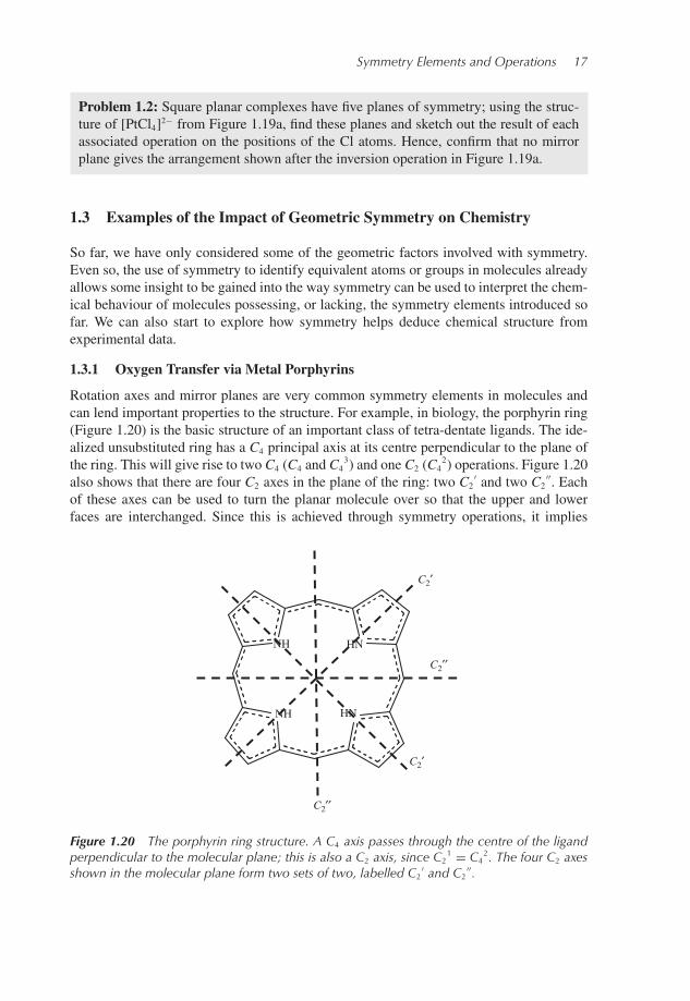
Rotation axes and mirror planes are very common symmetry elements in molecules andcan lend important properties to the structure. For example, in biology, the porphyrin ring(Figure 1.20) is the basic structure of an important class of tetra-dentate ligands. The ide-alized unsubstituted ring has a C4 principal axis at its centre perpendicular to the plane ofthe ring. This will give rise to two C4 (C4 and C4
3) and one C2 (C42) operations. Figure 1.20
also shows that there are four C2 axes in the plane of the ring: two C2′ and two C2
′′. Eachof these axes can be used to turn the planar molecule over so that the upper and lowerfaces are interchanged. Since this is achieved through symmetry operations, it implies
NH HN
NH HN
C2′
C2′
C2′′
C2′′
Figure 1.20 The porphyrin ring structure. A C4 axis passes through the centre of the ligandperpendicular to the molecular plane; this is also a C2 axis, since C2
1 = C42. The four C2 axes
shown in the molecular plane form two sets of two, labelled C2′ and C2
′′.

18 Molecular Symmetry
that the two faces of the ring are identical. This does have important consequences forthe biological processes involving porphyrin rings. In particular, complexes of Fe2+ withmore elaborate porphyrin ligands are essential for the function of haem, which is involvedin oxygen storage in the haemoglobin component of blood. When it is oxygenated, thecentral Fe atom carries a single oxygen atom which sits above the plane of the ring and itis coordinated by part of the host protein structure from below. Since the two faces of theporphyrin ligand are linked by symmetry operations, it does not matter ‘which way up’ theporphyrin is orientated as it is incorporated into the protein.
1.3.2 Nuclear Magnetic Resonance: Chemical Equivalence
An important use of symmetry is as an aid in the determination of molecular structurefrom spectroscopic data. We often know the molecular formula of a new compound, butthis does not tell us the molecular structure. In a nuclear magnetic resonance (NMR) exper-iment, a macroscopic sample of an unknown compound is exposed to a strong magneticfield. Magnetic nuclei in the sample will have different energies depending on the orien-tation of their magnetic moment with respect to the external field. According to quantummechanics, the magnetic moment of a nucleus is dependent on its spin. For nuclei with aspin of 1/2, such as 1H or 13C, two states will be possible: one with the spin aligned withthe external field and one with the spin aligned opposite to the external field. The energydifference between these two states is small, of the same order of magnitude as the energyof a photon of radio-frequency electromagnetic radiation. This means that, if the sampleis probed using radio-frequency waves, we will see an absorption when the photon energyexactly matches the energy difference between the two magnetic states of the nucleus.
In NMR spectroscopy, the probe frequency of the radio waves is actually held fixed andin the original approach the magnetic field applied was scanned through a range of values.The energy difference between the two spin states will be altered as the field is scanned,and a strong absorption will be observed when the energy difference exactly matches theprobe radio-frequency. In most modern machines the ‘scanning’ process has been replacedby a pulsed approach, which allows all environments of a given nucleus to be analysedsimultaneously.
In addition to the magnetic field applied in the experiment, the nuclei also experiencethe magnetic field created by the electrons and other magnetic nuclei in the molecule. Theelectronic effect tends to be larger than the nuclear influence on the local magnetic field ata given nucleus and so the nuclear effects are only resolved in high-resolution spectra. Inthe following examples we will only consider low-resolution spectra, and so will ignorethe magnetic coupling between nuclei. The magnitude of the electronic contribution to thelocal magnetic field depends on how the electron density is distributed in the molecule; inparticular, the field from the valence electrons will depend on the other elements presentand the types of bonding holding the structure together. So, the energy separation betweenthe spin states depends not just on the applied field from the NMR machine, but alsoon the local chemical environment of the nucleus being probed. This makes NMR anextremely useful technique in chemistry, because the positions of the NMR bands provideinformation on the molecular structure of the sample.
Generally, NMR spectra are plotted in terms of chemical shifts, which are the absorp-tion frequency differences between the sample nuclei and the same element in a laboratory

Symmetry Elements and Operations 19
standard. For carbon (13C) and hydrogen (1H) NMR experiments, a commonly usedstandard is tetramethylsilane (TMS). The chemical shift δ is defined as
δ = ν − νTMS
νTMS
× 106 (1.1)
where ν is the absorption frequency of the sample atoms and νTMS is the absorption of thecorresponding element (13C or 1H) in the standard. This chemical shift is dimensionless,since the reference absorption frequency appears in the denominator; this ensures thatexperiments on spectrometers with different probe frequencies give the same chemicalshift values for a given sample. The difference in frequencies observed between samplesand the standard is typically only a few kilohertz, whereas the probe frequency will be inthe 200–1000 MHz range. Hence, the factor of 106 is introduced to give chemical shiftsthat can be quoted using simple numbers, typically 0–12 for 1H NMR, and the shifts arequoted as parts per million (ppm).
The chemical shifts from a 1H NMR spectrum are used as an indication of the chemicalenvironment of each proton in the molecule of the sample. If two hydrogen atoms arelinked by a symmetry operation, then they will have the same environment and are referredto as chemically equivalent. The line in the 1H NMR spectrum for each will occur at exactlythe same position, and so the intensity of the peak at this chemical shift will be twice thatof a hydrogen atom in a unique environment, i.e. not linked to any other hydrogen atomsby symmetry operations. This allows us to use the intensity of the peaks as an indicationof the number of equivalent hydrogen atoms in a molecule and so may help to determinethe sample’s molecular structure.
As an example, Figure 1.21 shows a computer-generated 1H NMR spectrum for a com-pound with the chemical formula C8H14. There are several possibilities for the molecularstructure of this sample, two of which are given in Figure 1.22. The spectrum shows twopeaks with the lower chemical shift having a height six times that of the other signal.
013 2
Chemical shift (ppm)
Inte
nsity
Figure 1.21 A 1H NMR spectrum for a compound with the chemical formula C8H14
generated using the ChemDraw package.
20 Molecular Symmetry
dimethylcyclohexene
(a) (b)
bicyclo[2.2.2]octane
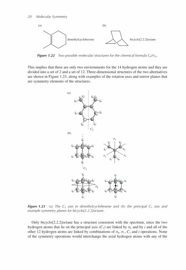
Figure 1.22 Two possible molecular structures for the chemical formula C8H14.
This implies that there are only two environments for the 14 hydrogen atoms and they aredivided into a set of 2 and a set of 12. Three-dimensional structures of the two alternativesare shown in Figure 1.23, along with examples of the rotation axes and mirror planes thatare symmetry elements of the structures.
(b) C2
C3
(a)
i σh
σv σv
σv
Figure 1.23 (a) The C2 axis in dimethylcyclohexene and (b) the principal C3 axis andexample symmetry planes for bicyclo[2.2.2]octane.
Only bicyclo[2.2.2]octane has a structure consistent with the spectrum, since the twohydrogen atoms that lie on the principal axis (C3) are linked by σh and by i and all of theother 12 hydrogen atoms are linked by combinations of σh, σv, C3 and i operations. Noneof the symmetry operations would interchange the axial hydrogen atoms with any of the

Symmetry Elements and Operations 21
hydrogen atoms in the CH2 groups, and so there are two distinct sets of hydrogen atoms.This gives the same division of the hydrogen atoms between the two environments thatwas implied from the spectral data. The dimethylcyclohexene alternative has only a C2
axis and no other symmetry axes or planes. As we shall see below, this means that it hashydrogen atoms in at least three different environments, and so would be expected to givea more complex 1H NMR spectrum.
The absorption event in an NMR experiment takes a short, but finite, time. If the pro-ton in a 1H NMR experiment is moving rapidly, then it may experience more than oneenvironment on the time scale of the experiment and only the average chemical shift willbe observed. For example, methyl groups are usually undergoing rapid rotation at roomtemperature, and so the three hydrogen atoms will appear equivalent even though theymay not be linked by symmetry operations. In the spectrum of dimethylcyclohexene wewould see only a single chemical shift for all six of the methyl protons, since the twomethyl groups are linked by symmetry operations in the static structure. Similarly, molec-ular motion would be expected to cause the hydrogen atoms of each CH2 group in the ringto interchange rapidly from axial to equatorial as the ring changes its conformation. The C2
axis implies that the two CH2 groups adjacent to the methylated carbon atoms are equiv-alent and that the remaining CH2 groups are also equivalent to one another. This gives atleast three distinct 1H NMR signals.
This type of analysis can also give some information on the dynamics of molecularmotion. Figure 1.24 shows the structure of Al2(CH3)6. The symmetry axes and mirror
AlH3C
H3C
C2(Z )
C2(Y )
C2(X )
H3
C
CH3
AlCH3
CH3
AlH3C
H3C
H3
C
C
AlCH3
CH3
σ (XZ )
σ (XY )
σ(YZ )
(a)
(b)
H3
Figure 1.24 The structure of Al2(CH3)6 showing (a) the rotation axes and (b) mirror planesassuming the structure of the methyl group can be ignored.

22 Molecular Symmetry
(a) (b)
Figure 1.25 1H NMR spectra of Al2(CH3)6: (a) at −40 ◦C; (b) at 20 ◦C.
planes for the structure are illustrated assuming that the internal structure of the methylgroups can be ignored due to the rapid rotation discussed above. Using the symmetryoperations, we see that the methyl groups form two sets: The four methyl groups thathave only one bond to an Al atom (terminal methyl groups) and the two methyl groupsthat bridge between Al atoms. Figure 1.25a shows the 1H NMR spectrum for Al2(CH3)6
taken at a temperature of −40 ◦C. As expected, we see two chemical shifts, with the signalfor the terminal methyl hydrogen atoms more intense than that for the hydrogen atomsof the bridging methyl groups. However, a spectrum of the same sample taken at 20 ◦Cshows only a single peak, as illustrated in Figure 1.25b. This peak has a chemical shift inbetween the values found for the terminal and bridging methyl hydrogen atoms at lowertemperature. This suggests that at 20 ◦C there is a rapid interchange of the terminal andbridging methyl groups so that the hydrogen atoms sample both environments. A possiblemechanism for this process is shown in Figure 1.26. Here, exchange is achieved withoutdissociation of the dimer, a bond between an Al and bridging methyl group is broken bythermal excitation and then a simple rotation converts the methyl group labelled C1H3 fromterminal to bridging.
AlH3C H3C H3C
H3CH3CCH3
AlCH3
CH3
CH3Al
CH3
AlAlH3CH3C
H3C
CH3
AlCH3
C1H3
C1H3 C1H3
Figure 1.26 Possible mechanism for the rapid interchange of terminal and bridging methylgroups in Al2(CH3)6.
1.4 Summary
Symmetry elements are imaginary geometrical entities that are the signature of symmetryproperties in objects. So far, we have seen that a line of symmetry is required for a rotation

Symmetry Elements and Operations 23
axis, a plane for a reflection and a single point for inversion. The symmetry element isthe set of points that are not moved when the corresponding symmetry operation takesplace.
Symmetry operations are the actions, such as rotations or reflections, that can be used totransform an object in such a way that, after the operation, it is indistinguishable from thestarting point.
The symmetry elements and operations of a molecule are given standard symbols,including:
• Proper rotation axes, labelled Cn, where n is the axis order. The highest order axispresent for a given molecule is called the principal axis and defines the vertical directionused to orientate the molecule in space.
• Reflection planes, labelled σ , with three possible subscripts:
– σv, a vertical mirror plane, contains the principal axis – if there are horizontal C2 axes,then σv will also contain those of highest priority;
– σd, a dihedral mirror plane, also contains the principal axis – if there are horizontal C2
axes, then σd will bisect the angle between those of highest priority;– σh, a horizontal mirror plane, is perpendicular to the principal axis.
• Inversion centre, labelled i, has a single point as the symmetry element. Inversionrequires each point in the molecule to have an equivalent point on the opposite sideof the centre of symmetry and equidistant from it. A molecule may have at most onepoint of inversion.
Atoms in a molecule that are linked by symmetry operations have identical chemicalenvironments, and so identical NMR chemical shifts.
1.5 Self-Test Questions
These questions are designed to give you practice at applying the concepts learned in thischapter. Most of the questions for this chapter require you to visualize the geometry of amolecule, and you may find it useful to construct models. In the illustrations here, as in therest of the text, we continue to use the convention that C atoms are not explicitly labelledin organic molecules and hydrogen atoms are omitted unless the geometry is ambiguouswithout them. The ‘flying wedge’ convention is also used to indicate bonds above andbelow the plane of the paper.
1. For each of the molecules in Figure 1.27 identify all of the rotation axes present, giv-ing the order of each axis and describing any that form a set of identical axes. Youshould make sketches of the molecules viewed from different directions to illustrateyour answer.
2. Give the orders of the principal axes for the molecules illustrated in Figure 1.27.3. Identify all the mirror planes present in the molecules of Figure 1.27 and use the rotation
axes you have found to label them as σv, σd or σh.

24 Molecular Symmetry
OO
H
H
H
H
H
H
H
F
H
H
RuFe
(a) (b)
(e) (f ) (g ) (h )
(c) (d)
( j)(i)
(k) (l)
H
FH
F
H
O
H F
Cyclohexane,boat conformation
H
H
H
H
H
H
H
H
H
H
H
H
Cyclohexane, chairconformation
HH
H
H
H
H
H
H
H
H
H
H
Figure 1.27 Example molecules for symmetry analysis.
4. How many distinct 1H NMR peaks would you expect for each molecule containing Hatoms in Figure 1.27?
5. Draw molecular structures of each of the isomers of difluorobenzene and identify allaxes and mirror planes of symmetry for each case.
Further Reading
Crystal symmetry is covered in several texts, including:Senechal, M. (1990) Crystalline Symmetries: An Informal Mathematical Introduction. Adam Hilger
(ISBN 0-7503-0041-8).Franzen HF (1994) Physical Chemistry of Solids, Basic Principles of Symmetry and Stability of
Crystalline Solids. World Scientific Publishing (ISBN 9-8102-1154-6).