Embed Size (px)
Citation preview
Progress In Electromagnetics Research B, Vol. 29, 1–22, 2011
SYMMETRICAL PYRAMIDAL HORN ANTENNAS BASEDON EBG STRUCTURES
I. Khromova, I. Ederra, and R. Gonzalo
Antenna GroupPublic University of Navarra, Pamplona, Navarra E31006, Spain
B. P. de Hon
Department of Electrical EngineeringEindhoven University of Technology5600 MB Eindhoven, The Netherlands
Abstract—This paper presents a novel pyramidal (EH) horn antennabased on Electromagnetic Band Gap structures (EBGs). The reportedpyramidal woodpile-based horn antenna possesses a symmetricalradiation pattern and a wide operating frequency range. Suchantennas can substitute metallic horns in certain circumstances, whichis especially valuable for millimetre and THz devices. The principle ofcreating EH-horn antennas in the woodpile structure is explained indetail. In particular, this paper presents the design of a symmetricalwoodpile EH-horn antenna operating at frequencies around 110 GHz.The reported antenna exhibits a wide operating bandwidth (more than10%), while possessing high directivity and radiation efficiency equalto 16.35 dBi and −0.55 dB (88%) respectively.
1. INTRODUCTION
In recent years, a great part of scientific and engineering research hasbeen aimed at designing and fabricating novel microwave and opticaldevices based on Electromagnetic Band Gap structures (EBGs) [1–6],also known as photonic crystals. These devices open a new chapterin the world of microwave and THz applied science and engineeringas they offer new advantages, such as avoiding metals or allowing forintegrated devices. The great effort in creating new concepts of use and
Received 4 February 2011, Accepted 7 March 2011, Scheduled 14 March 2011Corresponding author: Irina Khromova ([email protected]).
2 Khromova et al.
precise fabrication techniques promises to result in a real breakthroughfor various fields of applications [7–11].
An EBG structure is a periodic, normally dielectric structure withcertain geometry and dimensions, exhibiting in its spectral behavior aso called band gap — a range of frequencies, at which electromagneticwaves are not allowed to propagate in the structure. The EBGs, knownalso as photonic crystals in optics, have been attracting attention sincedecades ago. Having found almost no application in radio-physics andhaving triumphed in optics, they are now penetrating into the worldof microwave and THz engineering, where the EBG technology opensup the possibility of creating compact and well-matched devices.
The EBGs have already been widely exploited for antenna-relatedapplications. They were used as substrates, superstrates and coatingsfor shaping and improving the radiation characteristics of antennasof different types [12–17]. In particular, their ability of confiningand guiding electromagnetic energy has opened up new applicationsand solutions in microwave and optical devices design. These novelconcepts can be realized in EBGs with cavities or defects [2–5, 18, 19],which can function as resonators, waveguides and even horn antennas.Point defects in EBGs were applied to antennas in order to achievelarger directivities and higher efficiencies [20–22]. These compactdefect-based antennas however resulted to be limited in terms of theiroperating bandwidth.
As demonstrated in [23–28], EBG structures themselves can serveas novel type of horn antennas, when a corresponding pyramidal-shaped hollow defect is introduced in the periodic structure. Thishollow defect should provide an adiabatic transition between a feedingEBG waveguide and the free space. In the above cited papers creatinga gradual tapering of hollow waveguides in a woodpile structure [29, 30]was proposed. The horn is realized within one woodpile layerby bending the woodpile rods, parallel to the direction of energypropagation. In this way a radiating aperture within the containingwoodpile slab can be created.
Among the main interesting and promising propertied of EBGhorn antennas there are the large operating bandwidth (equal to thebandwidths of the feeding EBG waveguides in two-dimensional (2D)systems [23] and comparable to the ones in three-dimensional (3D)cases); high directivity levels controlled by the horn antenna flareangles; low losses at high frequencies due to the absence of metals(provided the EBG structure is fabricated with sufficient precision);and scalability of the antenna designs, which allows one to use thesame concepts for very different frequency ranges.
Despite offering a wide spectrum of applications the EBG horn
Progress In Electromagnetics Research B, Vol. 29, 2011 3
antennas in their present form (implemented by introducing a layer ofbend dielectric rods in the embedding woodpile structure) still haveseveral fundamental drawbacks.
Until now only sectoral H-horn antennas based on 3D EBGstructures have been designed. In the proposed configurations theelectric field is parallel to the woodpile stacking direction. Thus theE-plane dimensions of such horn antennas are determined by thethickness of the woodpile bars, since these horns are created withina single woodpile layer. Such a narrow and pre-determined apertureleads to a broad beam in the E-plane, which besides is non-symmetricaldue to the absence of mirror symmetry in the stacking direction of thewoodpile structure. However, the linear array proposed in [27] andthe evanescently fed array proposed in [28] can improve the E-planeradiation pattern of the system.
Reducing the E-plane beamwidth would require creating apyramidal horn antenna. The difficulty of creating a pyramidal hornbased on a defect-containing woodpile structure lies in the complexityof the embedding medium itself. Looking at the woodpile structure,one can easily notice that simply bending the rods in both E- andH-plane cannot provide us with a proper pyramidal horn defect.
Even an H-horn realized as a defect in several adjacent woodpilelayers cannot be designed in a straightforward way as it will bedemonstrated below. Yet such an antenna would be a solution whenusing EBG waveguides, implemented as hollow defects in severaladjacent layers of the woodpile structure. For instance, a three-layer woodpile waveguide [10], which can be well-matched to standardmetallic input/output waveguides, would be coupled to a three-layerwoodpile horn antenna in a more natural way than to a single-layerwoodpile horn antenna.
This paper presents a solution to the above stated problem relatedto the absence of symmetry in the EBG horn antennas, and alsoproposes an approach, allowing one to create a pyramidal EBG hornantenna. Firstly, the main difference between a metallic horn antennaand an EBG horn antenna is given. It is explained why a simple andstraightforward introduction of a horn-shaped defect cannot create anEBG horn antenna. Ways of realizing symmetrical horns and hornswith apertures in both E- and H-planes within woodpile slabs arepresented. Finally, the effect of the tolerances in the performance ofsuch antennas is also studied.
For all the configurations of the EBG horn antennas presented inthis paper the following woodpile structure parameters were chosen:period a = 1mm, woodpile rods width d1 = 0.3mm and heightd2 = 0.33mm. The structure is made of silicon with dielectric
4 Khromova et al.
permittivity 11.9. This woodpile exhibits a band gap at around 95–125GHz. However, all the proposed structures are scalable and thesame principles and ideas can be applied to antennas operating atdifferent frequency ranges.
2. PROPERTIES OF EBG HORN ANTENNAS
In order to understand the behavior of the EBG horn antennas, it isnecessary to understand, first of all, that the field structure inside anEBG horn antenna, EBG waveguide or EBG cavity, is by no meansanalogous to the one inside metallic horns, waveguides or resonators.However, there is an evident resemblance between those two, andthis fact allows the above mentioned devices to function in a similarway. Adiabatic widening of a metallic waveguide results in creating ateach point along the direction of energy propagation a local effectivewaveguide, which supports a fundamental mode at a frequency lowerthan the frequency of the fundamental mode of the initial feedingwaveguide. At the same time, if the widening is gradual enough, itis possible to propagate the initial fundamental mode along the hornadapting its shape to something resembling a plane wave.
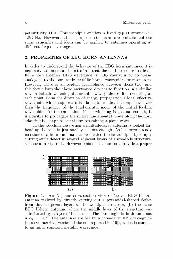
In the woodpile case when a multiple-layer antenna is looked for,bending the rods in just one layer is not enough. As has been alreadymentioned, a horn antenna can be created in the woodpile by simplycutting out a defect in several adjacent layers of a woodpile structure,as shown in Figure 1. However, this defect does not provide a proper
(a) (b)
Figure 1. An H-plane cross-section view of (a) an EBG H-hornantenna realized by directly cutting out a pyramidal-shaped defectfrom three adjacent layers of the woodpile structure, (b) the sameEBG H-horn antenna, where the middle layer of the structure wassubstituted by a layer of bent rods. The flare angle in both antennasis αH = 10◦. The antennas are fed by a three-layer EBG waveguide(non-symmetrical version of the one reported in [10]), which is coupledto an input standard metallic waveguide.
Progress In Electromagnetics Research B, Vol. 29, 2011 5
functioning of the system as a horn antenna. In other words, it doesnot create an adiabatic transition between an EBG waveguide and thefree-space due to the periodicity of the embedding structure.
In order to explain this behavior, the antenna configurationpresented in Figure 1(b) will be used. It combines the bended bars inthe layer where the bars are parallel to the waveguide axis, describedin the literature [23–28], where well-functioning EBG horn antennaswere reported, with cut bars in the top and bottom layers. However,since the EBG waveguide is periodical, the straightforward analogyof adiabatic transition in metallic horns is not applicable in this case.Even flaring it out gradually will result in an abrupt appearance ofwider effective EBG waveguides (in the cross-sections of the hornantenna), which support higher-order modes.
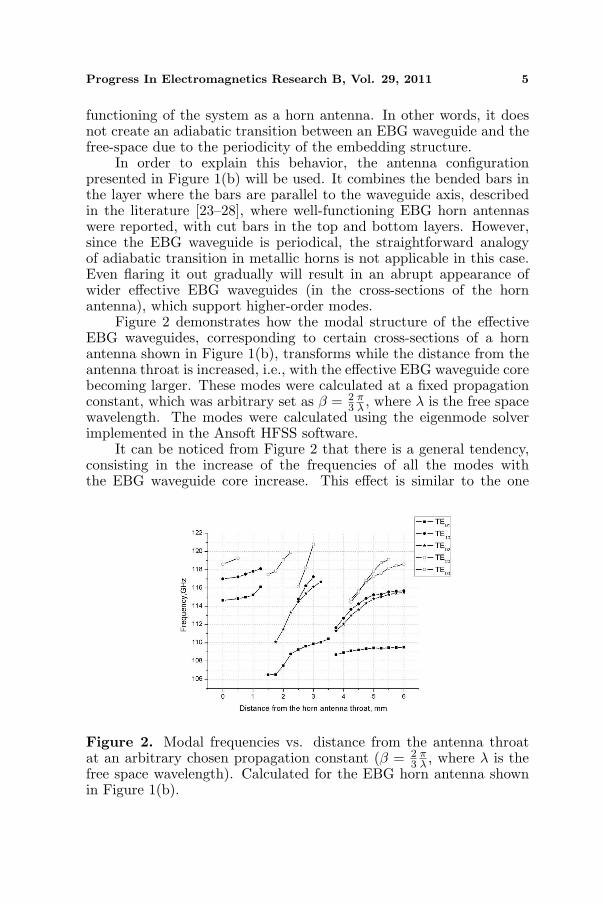
Figure 2 demonstrates how the modal structure of the effectiveEBG waveguides, corresponding to certain cross-sections of a hornantenna shown in Figure 1(b), transforms while the distance from theantenna throat is increased, i.e., with the effective EBG waveguide corebecoming larger. These modes were calculated at a fixed propagationconstant, which was arbitrary set as β = 2
3πλ , where λ is the free space
wavelength. The modes were calculated using the eigenmode solverimplemented in the Ansoft HFSS software.
It can be noticed from Figure 2 that there is a general tendency,consisting in the increase of the frequencies of all the modes withthe EBG waveguide core increase. This effect is similar to the one
Figure 2. Modal frequencies vs. distance from the antenna throatat an arbitrary chosen propagation constant (β = 2
3πλ , where λ is the
free space wavelength). Calculated for the EBG horn antenna shownin Figure 1(b).
6 Khromova et al.
reported in [18] and happens due to simultaneous lowering of theeffective dielectric permittivity of the region occupied by the mode(in the transverse cross-section of the EBG waveguide).
At the same time, the frequencies of all the modes drop sharplyat certain distances. For instance, the frequency of the TE01 modedrops from 116.11 GHz to 106.51 GHz at a distance of 1.5 mm from theantenna throat. This happens due to an abrupt switch between anEBG waveguide with a core occupying a lower number of EBG unitcells to an EBG waveguide with a core occupying a higher numberof EBG unit cells. In this case due to larger geometrical sizes of themodes, the frequencies drop. At these distances the fundamental modeof the considered feeding EBG waveguide excites higher-order modes inthe wider effective EBG waveguides, whenever the existence of thesemodes is permitted within the band gap, see Figure 3. As for thefact that in [23–28] the EBG horn antenna realized as a layer of bentwoodpile rods functions well, one has to keep in mind that those arebasically one-dimensional systems, where of course a gradual taperingis rather easy to achieve.
On the other hand, EBG waveguides are very different frommetallic ones. The modes guided in EBG waveguides are not boundto the physical core boundary, as the field does not have to becomezero as it does at the metallic walls. The shape of the fundamentalmode of a three-layer EBG waveguide (a non-symmetrical analogy ofthe one reported in [10]) is however very similar to that of a metallicwaveguide.
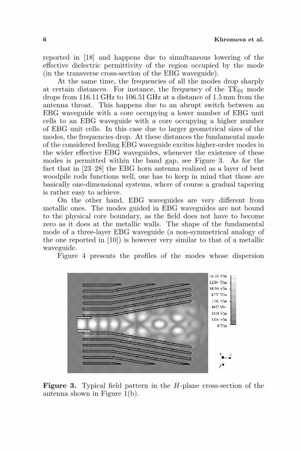
Figure 4 presents the profiles of the modes whose dispersion
Figure 3. Typical field pattern in the H-plane cross-section of theantenna shown in Figure 1(b).
Progress In Electromagnetics Research B, Vol. 29, 2011 7
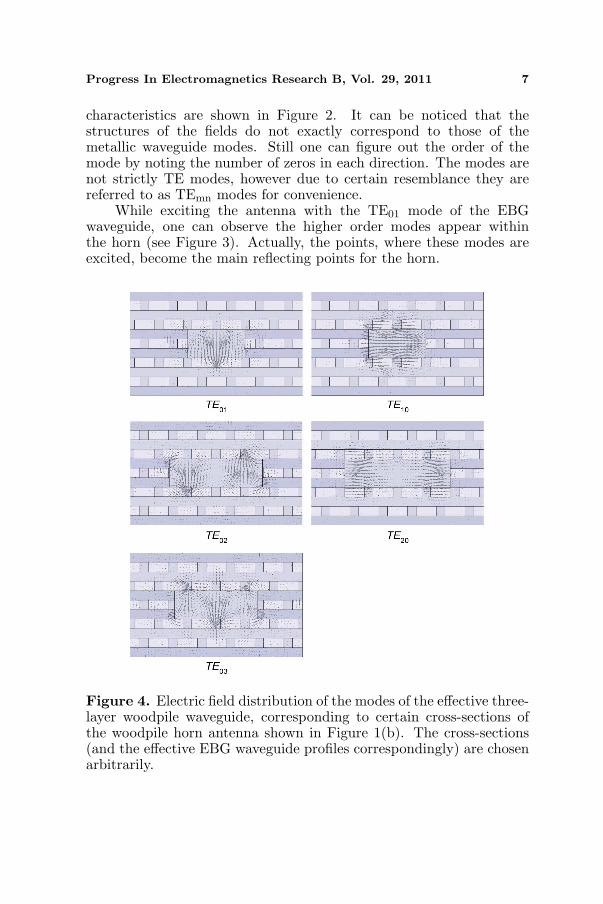
characteristics are shown in Figure 2. It can be noticed that thestructures of the fields do not exactly correspond to those of themetallic waveguide modes. Still one can figure out the order of themode by noting the number of zeros in each direction. The modes arenot strictly TE modes, however due to certain resemblance they arereferred to as TEmn modes for convenience.
While exciting the antenna with the TE01 mode of the EBGwaveguide, one can observe the higher order modes appear withinthe horn (see Figure 3). Actually, the points, where these modes areexcited, become the main reflecting points for the horn.
Figure 4. Electric field distribution of the modes of the effective three-layer woodpile waveguide, corresponding to certain cross-sections ofthe woodpile horn antenna shown in Figure 1(b). The cross-sections(and the effective EBG waveguide profiles correspondingly) are chosenarbitrarily.

8 Khromova et al.
3. NEW CONCEPT OF WOODPILE-BASED HORNANTENNAS
In this paper, a solution for the problem described in the previoussection is proposed. The main concept of providing an adiabatictransition between a waveguide and the free-space lies in creatingreal “EBG-walls” analogous to metallic walls in conventional hornantennas. It can be done by turning the whole EBG structure atan angle equal to horn antenna flare angle (Figure 5). Doing so, oneshifts all the nodes of the EBG lattice and avoids creating larger EBGwaveguides along the direction of wave propagation. Instead an “EBGwall” appears around the horn antenna, where the reflection happensdue to the band gap effect and at each position along the horn thewave faces the same boundary conditions. In such a system the fieldbehaves in principle in the same way as it does within a metallic hornantenna.
Figure 5. A woodpile-based H-horn antenna realized by turning theEBG “walls” at the antenna flare angle (10◦).
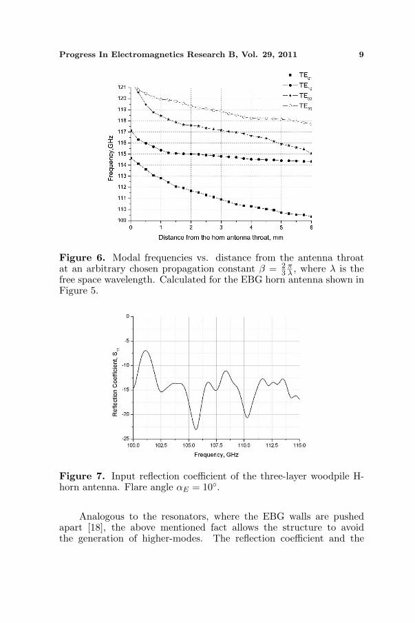
Figure 6 shows how the modal frequencies of the effective EBGwaveguide (corresponding to certain cross-sections of the horn antennashown in Figure 5) change with the increase of the distance from theantenna throat. As those in Figure 2, the modes in Figure 6 werecalculated at a fixed propagation constant β = 2
3πλ , where λ is the free
space wavelength.Unlike the previous case the frequencies of the modes in Figure 6
decrease with the increase of the effective EBG waveguide size. Atthe same time there are no sudden drops in the modal frequencies andthus, once excited, a mode inside this EBG horn antenna is not likelyto break up into higher-order modes. The single-layer EBG antennawith bent rods [26–28] realizes the same principle within one woodpilelayer.
Progress In Electromagnetics Research B, Vol. 29, 2011 9
Figure 6. Modal frequencies vs. distance from the antenna throatat an arbitrary chosen propagation constant β = 2
3πλ , where λ is the
free space wavelength. Calculated for the EBG horn antenna shown inFigure 5.
Figure 7. Input reflection coefficient of the three-layer woodpile H-horn antenna. Flare angle αE = 10◦.
Analogous to the resonators, where the EBG walls are pushedapart [18], the above mentioned fact allows the structure to avoidthe generation of higher-modes. The reflection coefficient and the
10 Khromova et al.
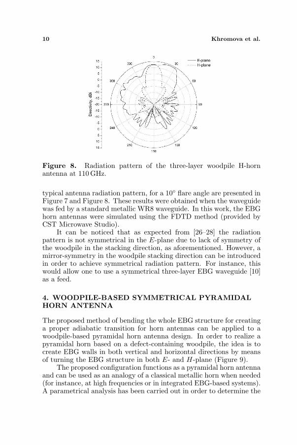
Figure 8. Radiation pattern of the three-layer woodpile H-hornantenna at 110 GHz.
typical antenna radiation pattern, for a 10◦ flare angle are presented inFigure 7 and Figure 8. These results were obtained when the waveguidewas fed by a standard metallic WR8 waveguide. In this work, the EBGhorn antennas were simulated using the FDTD method (provided byCST Microwave Studio).
It can be noticed that as expected from [26–28] the radiationpattern is not symmetrical in the E-plane due to lack of symmetry ofthe woodpile in the stacking direction, as aforementioned. However, amirror-symmetry in the woodpile stacking direction can be introducedin order to achieve symmetrical radiation pattern. For instance, thiswould allow one to use a symmetrical three-layer EBG waveguide [10]as a feed.
4. WOODPILE-BASED SYMMETRICAL PYRAMIDALHORN ANTENNA
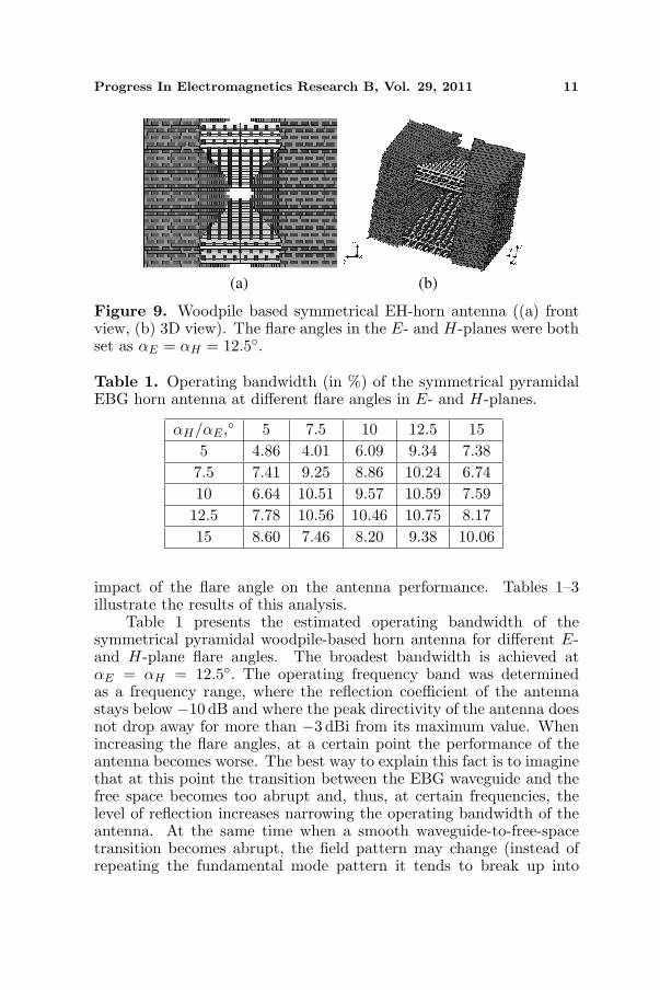
The proposed method of bending the whole EBG structure for creatinga proper adiabatic transition for horn antennas can be applied to awoodpile-based pyramidal horn antenna design. In order to realize apyramidal horn based on a defect-containing woodpile, the idea is tocreate EBG walls in both vertical and horizontal directions by meansof turning the EBG structure in both E- and H-plane (Figure 9).
The proposed configuration functions as a pyramidal horn antennaand can be used as an analogy of a classical metallic horn when needed(for instance, at high frequencies or in integrated EBG-based systems).A parametrical analysis has been carried out in order to determine the
Progress In Electromagnetics Research B, Vol. 29, 2011 11
(a) (b)
Figure 9. Woodpile based symmetrical EH-horn antenna ((a) frontview, (b) 3D view). The flare angles in the E- and H-planes were bothset as αE = αH = 12.5◦.
Table 1. Operating bandwidth (in %) of the symmetrical pyramidalEBG horn antenna at different flare angles in E- and H-planes.
αH/αE ,◦ 5 7.5 10 12.5 155 4.86 4.01 6.09 9.34 7.38
7.5 7.41 9.25 8.86 10.24 6.7410 6.64 10.51 9.57 10.59 7.59
12.5 7.78 10.56 10.46 10.75 8.1715 8.60 7.46 8.20 9.38 10.06
impact of the flare angle on the antenna performance. Tables 1–3illustrate the results of this analysis.
Table 1 presents the estimated operating bandwidth of thesymmetrical pyramidal woodpile-based horn antenna for different E-and H-plane flare angles. The broadest bandwidth is achieved atαE = αH = 12.5◦. The operating frequency band was determinedas a frequency range, where the reflection coefficient of the antennastays below −10 dB and where the peak directivity of the antenna doesnot drop away for more than −3 dBi from its maximum value. Whenincreasing the flare angles, at a certain point the performance of theantenna becomes worse. The best way to explain this fact is to imaginethat at this point the transition between the EBG waveguide and thefree space becomes too abrupt and, thus, at certain frequencies, thelevel of reflection increases narrowing the operating bandwidth of theantenna. At the same time when a smooth waveguide-to-free-spacetransition becomes abrupt, the field pattern may change (instead ofrepeating the fundamental mode pattern it tends to break up into
12 Khromova et al.
Table 2. Peak directivity (dBi) of the symmetrical pyramidal EBGhorn antenna at different flare angles in E- and H-planes.
αH/αE ,◦ 5 7.5 10 12.5 155 11.84 12.51 13.56 14.13 14.70
7.5 12.77 14.21 15.23 15.82 16.8210 15.09 15.45 16.31 17.13 17.75
12.5 13.39 15.46 16.17 16.35 17.3915 12.51 14.98 16.62 16.97 16.79
Table 3. Difference between beamwidths (in ◦) in E- and H-planes ofthe symmetrical pyramidal EBG horn antenna at different flare anglesin E- and H-planes at frequencies corresponding to peak directivitylevel.
αH/αE ,◦ 5 7.5 10 12.5 155 5 27.4 11.3 38.7 7.6
7.5 30.7 15.11 8.2 1.5 8.510 27 7.9 9.4 0.9 2.2
12.5 35.8 8.6 8.8 2 415 28.2 11.1 8.5 4.7 1.6
higher order modes), which can lead to lower directivity levels andsplitting of the main lobe into two or more lobes.
Studying the peak directivity of the antenna presented in Table 2and the difference between E- and H-plane beamwidths together withthe results presented in Table 1 permits one to conclude that theperformance of the antennas with αE = αH = 12.5◦ and αE = αH =15◦ are comparable in terms of the parameters concerned. Moreover,according to Table 3 the antenna appears to be slightly more directivewhen αE = αH = 15◦(22.1◦ in the E-plane and 23.7◦ in the H-plane)than when the flare angles are αE = αH = 12.5◦(23◦ in E-planeand 25◦ in the H-plane). However, in terms of the radiation patternand the level of side lobes the latter can still be given preference.Figure 10 compares the level of the side lobes throughout the operatingbandwidths of the two antennas, and it can be noticed that in thefrequency range around 107–110 GHz in the H-plane it stays around−3 dBi lower for the antenna with αE = αH = 12.5◦ when comparedto that of the wider flare angle antenna configuration.
The E- and H-plane flare angles of the antenna shown in Figure 9
Progress In Electromagnetics Research B, Vol. 29, 2011 13
(a) (b)
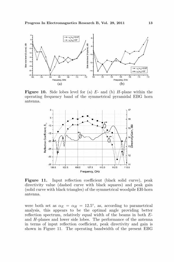
Figure 10. Side lobes level for (a) E- and (b) H-plane within theoperating frequency band of the symmetrical pyramidal EBG hornantenna.
Figure 11. Input reflection coefficient (black solid curve), peakdirectivity value (dashed curve with black squares) and peak gain(solid curve with black triangles) of the symmetrical woodpile EH-hornantenna.
were both set as αE = αH = 12.5◦, as, according to parametricalanalysis, this appears to be the optimal angle providing betterreflection spectrum, relatively equal width of the beams in both E-and H-planes and lower side lobes. The performance of the antennain terms of input reflection coefficient, peak directivity and gain isshown in Figure 11. The operating bandwidth of the present EBG
14 Khromova et al.
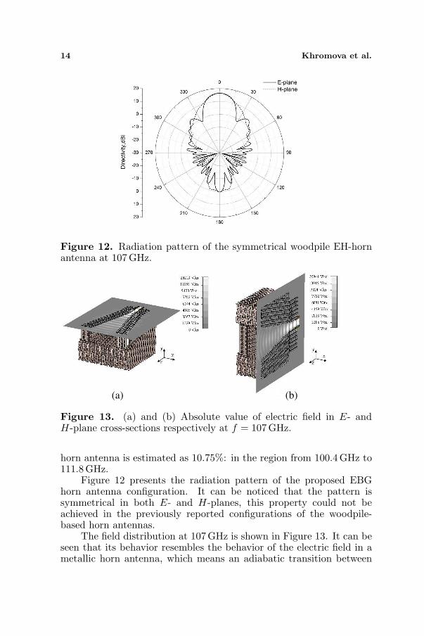
Figure 12. Radiation pattern of the symmetrical woodpile EH-hornantenna at 107 GHz.
(a) (b)
Figure 13. (a) and (b) Absolute value of electric field in E- andH-plane cross-sections respectively at f = 107GHz.
horn antenna is estimated as 10.75%: in the region from 100.4GHz to111.8GHz.
Figure 12 presents the radiation pattern of the proposed EBGhorn antenna configuration. It can be noticed that the pattern issymmetrical in both E- and H-planes, this property could not beachieved in the previously reported configurations of the woodpile-based horn antennas.
The field distribution at 107GHz is shown in Figure 13. It can beseen that its behavior resembles the behavior of the electric field in ametallic horn antenna, which means an adiabatic transition between
Progress In Electromagnetics Research B, Vol. 29, 2011 15
the feeding waveguide mode and the free space is achieved in theproposed EBG EH-horn antenna.
Thus, a new concept of designing woodpile-based antennasallowing one to realize pyramidal horns is presented. Turning theEBG slabs surrounding the actual core of the horn provides a gradualtapering, which means a smooth transition between the EBG feedingwaveguide and the free space. The proposed pyramidal horn antennabased on a woodpile structure demonstrates good performance andcompetitive parameters.
The proposed pyramidal EBG horn antennas can be used fordesigning integrated devices based on EBG technology. They can beeasily matched to other EBG-based components, such as waveguides,filters, power-splitters, etc., implemented within the same slab of theembedding periodic structure.
5. SENSITIVITY ANALYSIS
Since the performance of the EBG-based devices tends to stronglydepend on the geometry of the structure, a sensitivity analysis of theproposed EBG horn antenna performance with respect to its maingeometrical parameters was performed. In particular, the impact ofantenna starting point with respect to the EBG waveguide and theantenna flare angle was evaluated.
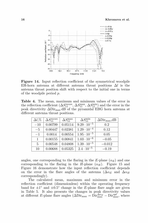
Due to periodicity of the embedding medium placing the antennathroat in the optimal position with respect to the EBG waveguide isimportant. This optimal position should be calculated by means ofa parametrical analysis for each antenna in particular. At the sametime it is important to see how small errors in antenna positioningaffect the performance of the system. Figure 14 presents the inputreflection coefficient of the antennas, where the position of the hornthroat is shifted by ∆l with respect to the optimal position. Withinthe operating frequency band (100.4 GHz–111.8 GHz) the calculatedmean, maximum and minimum error in the reflection coefficient(dimensionless) in the previous cases are given in Table 4. Thereflection coefficient is slightly affected by this shift and even for a10% error the maximum change is relatively small. Table 4 also showsthe change in the peak directivity value occurring when the antennathroat is shifted from its optimal position (∆Dirmax = Dir∆l
max−Diroptmax,
where Dir∆lmax is the peak directivity of the antenna with a displaced
throat and Diroptmax = 16.35 dBi is the peak directivity of the antenna
with the correct position of the throat).Another important geometrical parameter of the horn antenna
is the flare angle. In case of the pyramidal horn there are two
16 Khromova et al.
Figure 14. Input reflection coefficient of the symmetrical woodpileEH-horn antenna at different antenna throat positions ∆l is theantenna throat position shift with respect to the initial one in termsof the woodpile period p.
Table 4. The mean, maximum and minimum values of the error inthe reflection coefficient (∆Smean
11 , ∆Smax11 , ∆Smin
11 ) and the error in thepeak directivity ∆Dirmax dB of the pyramidal EBG horn antenna atdifferent antenna throat positions.
∆l,% ∆Smean11 ∆Smax
11 ∆Smin11 ∆Dirmax,dB
−10 0.00799 0.05114 9.29 · 10−5 0.2−5 0.00447 0.02381 1.29 · 10−4 0.12−1 0.0014 0.00554 1.95 · 10−5 0.051 0.00155 0.00841 1.03 · 10−6 −0.055 0.00548 0.04808 1.39 · 10−5 −0.01210 0.00688 0.05325 2.4 · 10−5 −0.19
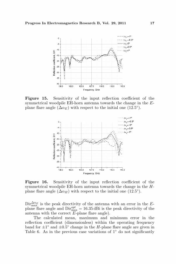
angles, one corresponding to the flaring in the E-plane (αE) and onecorresponding to the flaring in the H-plane (αH). Figure 15 andFigure 16 demonstrate how the input reflection coefficient dependson the error in the flare angles of the antenna (∆αE and ∆αH
correspondingly).The calculated mean, maximum and minimum error in the
reflection coefficient (dimensionless) within the operating frequencyband for ±1◦ and ±0.5◦ change in the E-plane flare angle are givenin Table 5. It also presents the changes in peak directivity valuesat different E-plane flare angles (∆Dirmax = Dir∆αE
max − Diroptmax, where
Progress In Electromagnetics Research B, Vol. 29, 2011 17
Figure 15. Sensitivity of the input reflection coefficient of thesymmetrical woodpile EH-horn antenna towards the change in the E-plane flare angle (∆αE) with respect to the initial one (12.5◦).
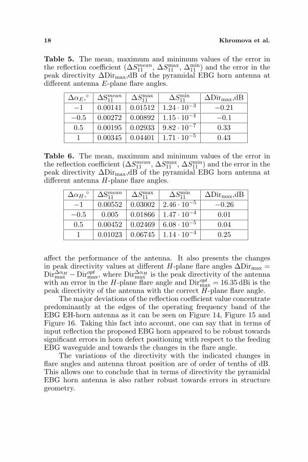
Figure 16. Sensitivity of the input reflection coefficient of thesymmetrical woodpile EH-horn antenna towards the change in the H-plane flare angle (∆αH) with respect to the initial one (12.5◦).
Dir∆αEmax is the peak directivity of the antenna with an error in the E-
plane flare angle and Diroptmax = 16.35 dBi is the peak directivity of the
antenna with the correct E-plane flare angle).The calculated mean, maximum and minimum error in the
reflection coefficient (dimensionless) within the operating frequencyband for ±1◦ and ±0.5◦ change in the H-plane flare angle are given inTable 6. As in the previous case variations of 1◦ do not significantly
18 Khromova et al.
Table 5. The mean, maximum and minimum values of the error inthe reflection coefficient (∆Smean
11 , ∆Smax11 , ∆min
11 ) and the error in thepeak directivity ∆Dirmax,dB of the pyramidal EBG horn antenna atdifferent antenna E-plane flare angles.
∆αE ,◦ ∆Smean11 ∆Smax
11 ∆Smin11 ∆Dirmax,dB
−1 0.00141 0.01512 1.24 · 10−3 −0.21−0.5 0.00272 0.00892 1.15 · 10−4 −0.10.5 0.00195 0.02933 9.82 · 10−7 0.331 0.00345 0.04401 1.71 · 10−5 0.43
Table 6. The mean, maximum and minimum values of the error inthe reflection coefficient (∆Smean
11 , ∆Smax11 , ∆Smin
11 ) and the error in thepeak directivity ∆Dirmax,dB of the pyramidal EBG horn antenna atdifferent antenna H-plane flare angles.
∆αH ,◦ ∆Smean11 ∆Smax
11 ∆Smin11 ∆Dirmax,dB
−1 0.00552 0.03002 2.46 · 10−5 −0.26−0.5 0.005 0.01866 1.47 · 10−4 0.010.5 0.00452 0.02469 6.08 · 10−5 0.041 0.01023 0.06745 1.14 · 10−4 0.25
affect the performance of the antenna. It also presents the changesin peak directivity values at different H-plane flare angles ∆Dirmax =Dir∆αH
max −Diroptmax, where Dir∆αH
max is the peak directivity of the antennawith an error in the H-plane flare angle and Diropt
max = 16.35 dBi is thepeak directivity of the antenna with the correct H-plane flare angle.
The major deviations of the reflection coefficient value concentratepredominantly at the edges of the operating frequency band of theEBG EH-horn antenna as it can be seen on Figure 14, Figure 15 andFigure 16. Taking this fact into account, one can say that in terms ofinput reflection the proposed EBG horn appeared to be robust towardssignificant errors in horn defect positioning with respect to the feedingEBG waveguide and towards the changes in the flare angle.
The variations of the directivity with the indicated changes inflare angles and antenna throat position are of order of tenths of dB.This allows one to conclude that in terms of directivity the pyramidalEBG horn antenna is also rather robust towards errors in structuregeometry.
Progress In Electromagnetics Research B, Vol. 29, 2011 19
6. CONCLUSION
In this paper, a novel pyramidal EBG horn antenna design and conceptwas presented. Previously reported woodpile based horn antennas wererestricted to be sectoral since the embedding medium did not allow tocreate apertures in both E- and H-planes by bending the woodpilebars. Moreover, the woodpile based horn antennas used to have a non-symmetrical radiation pattern due to the absence of mirror symmetryin the stacking direction of the embedding periodic structure. Theconcept presented in this paper lies in combining EBG slabs turned atdifferent angles in order to form a horn antenna. This approach allowsone to create apertures in both E- and H-planes and also to introducesymmetries which the embedding woodpile medium does not possess.Thus, a pyramidal woodpile-based horn antenna with a symmetricalradiation pattern can be designed.
We have shown that in order to provide an adiabatic transitionbetween an EBG waveguide and the free-space, one has to turn thewhole EBG structure at an angle equal to horn antenna flare angleand to create a slow and gradual aperture. Otherwise, if the latticenodes are not displaced along the way from the antenna throat to theantenna aperture, the abrupt changes in the horn cross-sections makethe initial electromagnetic mode break up into higher-order modes.
An F band silicon woodpile-based pyramidal horn antenna wasdesigned following this idea. The presented antenna operates within100.4GHz–111.8GHz according to the numerical simulation resultsand thus exhibits a 10.2% bandwidth. Its competitive parametersdemonstrate also that such EBG-based components can be consideredwhen designing integrate EBG-based devices and can serve asalternatives of metallic horns in certain situations. The presentedantenna thanks to certain degree of scalability of the overall systemcan be re-designed for different ranges of frequencies provided a propermaterial and dimensions are used for the embedding woodpile structuredesign.
ACKNOWLEDGMENT
Supported by the Spanish Ministry of Science and Innovation ProjectNos. TEC2009-11995 and CSD2008-00066.
REFERENCES
1. Yablonovitch, E., “Inhibited spontaneous emission in solid-statephysics and electronics,” Phys. Rev. Lett., Vol. 58, 2059–2062,
20 Khromova et al.
1987.2. John, S., “Strong localization of photons in certain disordered
dielectric superlattices,” Phys. Rev. Lett., Vol. 58, 2486, 1987.3. Meade, R. D., K. D. Brommer, A. M. Rappe, and
J. D. Joannopoulos, “Photonic bound states in periodic dielectricmaterials,” Phys. Rev. B, Vol. 44, No. 24, 13772–13774, 1991.
4. Joannopoulos, J. D., R. D. Meade, and J. N. Winn, PhotonicCrystals, Princeton University Press, 1995.
5. Joannopoulos, J. D., P. R. Villeneuve, and S. Fan, “Photoniccrystals: Putting a new twist on light,” Nature, Vol. 386, 143,1997.
6. Ho, K. M., C. T. Chan, and C. M. Soukoulis, “Existence of aphotonic gap in periodic dielectric structures,” Phys. Rev. Lett.,Vol. 65, 3152, 1990.
7. Ederra, I., R. Gonzalo, C. Mann, and P. de Maagt, “(Sub)mmwavecomponents and subsystems based on PBG technology,” Proc.IEEE AP-S Int. Symp. Dig., 1087–1090, 2003.
8. Ederra, I., et al., “EBG millimetre-wave components design,”Proc. 3rd ESA Workshop on Millimetre Wave Technology andApplications, 129–134, Espoo, Finland, May 21–23, 2003.
9. Ederra, I., et al., “Measurements of sub-mm and mm-wavecomponents and subsystems based on EBG technology,” Proc. 3rdESA Workshop on Millimetre Wave Technology and Applications,459–464, Espoo, Finland, May 21–23, 2003.
10. Ederra, I., I. Khromova, R. Gonzalo, N. Delhote, D. Baillargeat,A. Murk, B. E. J. Alderman, and P. de Maagt, “Electromagneticband gap waveguide for the millimeter range,” IEEE Trans. onMicrowave Theory and Techniques, Vol. 58, No. 7, 1734–1741,2010.
11. De Maagt, P., R. Gonzalo, Y. C. Vardaxoglou, and J. M. Baracco,“Electromagnetic bandgap antennas and components for mi-crowave and (sub)millimeter wave applications,” IEEE Trans. An-tennas Propag., Vol. 51, No. 10, 2667–2677, 2003.
12. Brown, E. R., C. D. Parker, and E. Yablonovitch, “Radiationproperties of a planar antenna on a photonic-crystal substrate,”J. Opt. Soc. Am. B, Vol. 10, No. 2, 404–407, 1993.
13. Gonzalo, R., I. Ederra, C. M. Mann, and P. de Maagt, “Radiationproperties of terahertz dipole antenna mounted on photoniccrystal,” Electronics Letters, Vol. 37, No. 10, 613–614, May 2001.
14. Ederra, I., R. Gonzalo, B. E. J. Alderman, P. G. Huggard,B. P. de Hon, M. C. van Beurden, A. Murk, L. Marchand, and
Progress In Electromagnetics Research B, Vol. 29, 2011 21
P. Maagt, “Electromagnetic band gap based planar imaging arrayfor 500 GHz,” IEEE Trans. on Microwave Theory and Techniques,Vol. 56, No. 11, 2556–2565, Nov. 2008.
15. Kesler, M. P., J. O. Maloney, and B. L. Shirley, “Antenna designwith the use of photonic band-gap materials as all-dielectric planarreflectors,” Microwave and Opt. Technology Lett., Vol. 11, No. 4,169–174, 1996.
16. Smith, G. S., M. P. Kesler, and J. G. Maloney, “Dipole antennasused with all-dielectric, woodpile photonic-bandgap reflectors:Gain, field patterns, and input impedance,” Microwave Opt.Technol. Lett., Vol. 21, No. 3, 191–196, 1999.
17. Zhao, Z., Q. Deng, H. Xu, C. Du, and X. Luo, “A sectoralhorn antenna based on the electromagnetic band-gap structures,”Microwave and Opt. Technology Lett., Vol. 50, No. 4, 965–969,2008.
18. Khromova, I., R. Gonzalo, I. Ederra, and P. de Maagt, “Resonancefrequencies of cavities in three-dimensional electromagnetic bandgap structures,” Journal of Appl. Phys., Vol. 106, No. 1, 014901-1–7, 2009.
19. Ozbay, E., B. Temelkuran, and M. Bayindir, “Microwaveapplications of photonic crystals,” Progress In ElectromagneticsResearch, Vol. 41, 185–209, 2003.
20. Serier, C., C. Cheype, R. Chantalat, M. Thevenot, T. Monediere,A. Reinex, and B. Jecko, “1-D photonic bandgap resonatorantenna,” Microwave Opt. Technol. Lett., Vol. 29, No. 5, 312–315,2001.
21. Cheype, C., C. Serier, M. Thevenot, T. Monediere, A. Reinex,and B. Jecko, “An electromagnetic bandgap resonator antenna,”IEEE Trans. Antennas Propag., Vol. 50, No. 9, 1285–1290, 2002.
22. Biswas, R., E. Ozbay, B. Temelkuran, M. Bayindir, M. M. Sigalas,and K. M. Ho, “Exceptionally directional sources with photonic-bandgap crystals,” J. Opt. Soc. Am. B, Vol. 11, 1684–189, 2001.
23. Weily, A. R., K. P. Esselle, and B. C. Sanders, “Photonic crystalhorn and array antennas,” Phys. Rev. E, Vol. 68, 016609-1–016609-6, 2003.
24. Moore, R. L., M. P. Kesler, J. G. Maloney, and B. L. Shirley, USPatent 5,689,275, 1997.
25. Weily, A. R., K. P. Esselle, B. C. Sanders, and T. S. Bird, “High-gain 1d ebg resonator antenna,” Microwave and Opt. TechnologyLett., Vol. 47, No. 2, 107–114, 2005.
26. Weily, A. R., K. P. Esselle, and B. C. Sanders, “Layer-by-layer

22 Khromova et al.
photonic crystal horn antenna,” Phys. Rev. E, Vol. 70, 037602-4,2004.
27. Weily, A. R., K. P. Esselle, T. S. Bird, and B. C. Sanders, “Lineararray of woodpile EBG sectoral horn antennas,” IEEE Trans.Antennas Propag., Vol. 54, No. 8, 2263–2274, 2006.
28. Khromova, I., I. Ederra, J. Teniente, R. Gonzalo, and K. Esselle,“Evanescently-fed electromagnetic band gap horn antennas andarrays,” IEEE Trans. Antennas Propag., 2010.
29. Ho, M., C. T. Chan, C. M. Soukoulis, R. Biswas, and M. Sigalas,“Photonic band gaps in three dimensions: New layer-by-layerperiodic structures,” Solid State Commun., Vol. 89, No. 6, 413–416, 1994.
30. Sozuer, H. S. and J. Dowling, “Photonic band calculations forwoodpile structures,” J. Mod. Opt., Vol. 41, No. 2, 231–239, 1994.


![PERFORMANCE COMPARISON OF PYRAMIDAL HORNS LOADED … · 2018-01-14 · exhibits monotonically increasing gain behavior, a salient feature of the horn antenna [2,17,18], a return loss](https://img.dokumen.tips/doc/110x75/5e96032ae78896401776064e/performance-comparison-of-pyramidal-horns-loaded-2018-01-14-exhibits-monotonically.jpg)


![DEVELOPMENT OF PYRAMIDAL MICROWAVE ABSORBER USING … · 692 Zahid et al. tripod to hold the horn antennas and the reference metal [42,43]. The angle between the pyramidal microwave](https://img.dokumen.tips/doc/110x75/601eb3dec472a52b94125873/development-of-pyramidal-microwave-absorber-using-692-zahid-et-al-tripod-to-hold.jpg)