Embed Size (px)
Citation preview
Workshop Manual AC
2(2)
Sterndrive
SX-M, SX-MTDDP-SM, DP-SMTD, DP-SMTD1
Transom Shield
SX-M, SX-MLT, SX-MACLT,SX-MHP, SX-MDA, SX-MDB
Sterndrive
Transom Shield

General Information . . . . . . . . . . . . . . . . . . .3
Transom Shield Assembly - SX-M . . . . . . .17
Transom Shield Assembly SX-MHP. . . . . .53
Upper Gear Housing . . . . . . . . . . . . . . . . . .89
SX Lower Gearcase . . . . . . . . . . . . . . . . . .145
DP-S Lower Gearcase . . . . . . . . . . . . . . . .179
Sterndrive Removal and Installation . . . .227
Trim/Tilt Hydraulic System . . . . . . . . . . . .241
Propellers . . . . . . . . . . . . . . . . . . . . . . . . . .259
VPA 7743008 07-2003 1

Notes . . . . . . . . . . . . . . . . . . . . . . . . . . . . . . . . . . . . . . . . . . . . . . . . . . . . . . . . . . . . . . . . . . . . . . . . . . .
. . . . . . . . . . . . . . . . . . . . . . . . . . . . . . . . . . . . . . . . . . . . . . . . . . . . . . . . . . . . . . . . . . . . . . . . . . .
. . . . . . . . . . . . . . . . . . . . . . . . . . . . . . . . . . . . . . . . . . . . . . . . . . . . . . . . . . . . . . . . . . . . . . . . . . .
. . . . . . . . . . . . . . . . . . . . . . . . . . . . . . . . . . . . . . . . . . . . . . . . . . . . . . . . . . . . . . . . . . . . . . . . . . .
. . . . . . . . . . . . . . . . . . . . . . . . . . . . . . . . . . . . . . . . . . . . . . . . . . . . . . . . . . . . . . . . . . . . . . . . . . .
. . . . . . . . . . . . . . . . . . . . . . . . . . . . . . . . . . . . . . . . . . . . . . . . . . . . . . . . . . . . . . . . . . . . . . . . . . .
. . . . . . . . . . . . . . . . . . . . . . . . . . . . . . . . . . . . . . . . . . . . . . . . . . . . . . . . . . . . . . . . . . . . . . . . . . .
. . . . . . . . . . . . . . . . . . . . . . . . . . . . . . . . . . . . . . . . . . . . . . . . . . . . . . . . . . . . . . . . . . . . . . . . . . .
. . . . . . . . . . . . . . . . . . . . . . . . . . . . . . . . . . . . . . . . . . . . . . . . . . . . . . . . . . . . . . . . . . . . . . . . . . .
. . . . . . . . . . . . . . . . . . . . . . . . . . . . . . . . . . . . . . . . . . . . . . . . . . . . . . . . . . . . . . . . . . . . . . . . . . .
. . . . . . . . . . . . . . . . . . . . . . . . . . . . . . . . . . . . . . . . . . . . . . . . . . . . . . . . . . . . . . . . . . . . . . . . . . .
. . . . . . . . . . . . . . . . . . . . . . . . . . . . . . . . . . . . . . . . . . . . . . . . . . . . . . . . . . . . . . . . . . . . . . . . . . .
. . . . . . . . . . . . . . . . . . . . . . . . . . . . . . . . . . . . . . . . . . . . . . . . . . . . . . . . . . . . . . . . . . . . . . . . . . .
. . . . . . . . . . . . . . . . . . . . . . . . . . . . . . . . . . . . . . . . . . . . . . . . . . . . . . . . . . . . . . . . . . . . . . . . . . .
. . . . . . . . . . . . . . . . . . . . . . . . . . . . . . . . . . . . . . . . . . . . . . . . . . . . . . . . . . . . . . . . . . . . . . . . . . .
. . . . . . . . . . . . . . . . . . . . . . . . . . . . . . . . . . . . . . . . . . . . . . . . . . . . . . . . . . . . . . . . . . . . . . . . . . .
. . . . . . . . . . . . . . . . . . . . . . . . . . . . . . . . . . . . . . . . . . . . . . . . . . . . . . . . . . . . . . . . . . . . . . . . . . .
. . . . . . . . . . . . . . . . . . . . . . . . . . . . . . . . . . . . . . . . . . . . . . . . . . . . . . . . . . . . . . . . . . . . . . . . . . .
. . . . . . . . . . . . . . . . . . . . . . . . . . . . . . . . . . . . . . . . . . . . . . . . . . . . . . . . . . . . . . . . . . . . . . . . . . .
. . . . . . . . . . . . . . . . . . . . . . . . . . . . . . . . . . . . . . . . . . . . . . . . . . . . . . . . . . . . . . . . . . . . . . . . . . .
. . . . . . . . . . . . . . . . . . . . . . . . . . . . . . . . . . . . . . . . . . . . . . . . . . . . . . . . . . . . . . . . . . . . . . . . . . .
. . . . . . . . . . . . . . . . . . . . . . . . . . . . . . . . . . . . . . . . . . . . . . . . . . . . . . . . . . . . . . . . . . . . . . . . . . .
. . . . . . . . . . . . . . . . . . . . . . . . . . . . . . . . . . . . . . . . . . . . . . . . . . . . . . . . . . . . . . . . . . . . . . . . . . .
. . . . . . . . . . . . . . . . . . . . . . . . . . . . . . . . . . . . . . . . . . . . . . . . . . . . . . . . . . . . . . . . . . . . . . . . . . .
. . . . . . . . . . . . . . . . . . . . . . . . . . . . . . . . . . . . . . . . . . . . . . . . . . . . . . . . . . . . . . . . . . . . . . . . . . .
. . . . . . . . . . . . . . . . . . . . . . . . . . . . . . . . . . . . . . . . . . . . . . . . . . . . . . . . . . . . . . . . . . . . . . . . . . .
. . . . . . . . . . . . . . . . . . . . . . . . . . . . . . . . . . . . . . . . . . . . . . . . . . . . . . . . . . . . . . . . . . . . . . . . . . .
. . . . . . . . . . . . . . . . . . . . . . . . . . . . . . . . . . . . . . . . . . . . . . . . . . . . . . . . . . . . . . . . . . . . . . . . . . .
. . . . . . . . . . . . . . . . . . . . . . . . . . . . . . . . . . . . . . . . . . . . . . . . . . . . . . . . . . . . . . . . . . . . . . . . . . .
. . . . . . . . . . . . . . . . . . . . . . . . . . . . . . . . . . . . . . . . . . . . . . . . . . . . . . . . . . . . . . . . . . . . . . . . . . .
. . . . . . . . . . . . . . . . . . . . . . . . . . . . . . . . . . . . . . . . . . . . . . . . . . . . . . . . . . . . . . . . . . . . . . . . . . .
. . . . . . . . . . . . . . . . . . . . . . . . . . . . . . . . . . . . . . . . . . . . . . . . . . . . . . . . . . . . . . . . . . . . . . . . . . .
. . . . . . . . . . . . . . . . . . . . . . . . . . . . . . . . . . . . . . . . . . . . . . . . . . . . . . . . . . . . . . . . . . . . . . . . . . .
2 VPA 7743008 07-2003
General Information
General InformationSterndrive Lubrication - SX Models . . . . . . . . . . . . . . 6
Adding Lubricant to Sterndrive . . . . . . . . . . . . . . . . . . . . . . . . 6Sterndrive Oil Capacity . . . . . . . . . . . . . . . . . . . . . . . . . . . . . . 6Draining and Filling Sterndrive . . . . . . . . . . . . . . . . . . . . . . . . 6
Sterndrive Lubrication - DP-S Models . . . . . . . . . . . . 8Adding Lubricant to Sterndrive . . . . . . . . . . . . . . . . . . . . . . . . 8Sterndrive Oil Capacity . . . . . . . . . . . . . . . . . . . . . . . . . . . . . . 8Draining and Filling Sterndrive . . . . . . . . . . . . . . . . . . . . . . . . 8Power Trim/Tilt-Fluid Level . . . . . . . . . . . . . . . . . . . . . . . . . . . 9
Off -Season Storage Preparations - All Models . . . . . 9Painting . . . . . . . . . . . . . . . . . . . . . . . . . . . . . . . . . . . . . . . . . . . 9Preparation for Boating After Storage . . . . . . . . . . . . . . . . . 10Gimbal Bearing and Universal Joints Lubrication . . . . . . . 10Recommendations For Antifouling Paints . . . . . . . . . . . . . . 11Painting The Stern Drive With Antifouling Paint . . . . . . . . . 12Paints For Stern drives . . . . . . . . . . . . . . . . . . . . . . . . . . . . . 12Painting The Hull With Antifouling Paint . . . . . . . . . . . . . . . 12Metric Conversion Chart . . . . . . . . . . . . . . . . . . . . . . . . . . . . 13Periodic Maintenance Chart . . . . . . . . . . . . . . . . . . . . . . . . . 16
Safety Warnings Before working on any part of a Volvo Penta sterndrive, read thesection called Safety at the end of this manual.
1Introduction This service manual is divided into sections concerning various systems and
assemblies. Refer to the Contents to locate the section covering the system or assembly requiring service. Each section title page has an additional listing that will describe the section’s contents in more detail. Be sure to read the Safety Section at the end of this manual, and pay special attention to all safety warnings as they appear throughout the text. Since models are subject to change at any time, some photos may not depict actual product.
VPA 7743008 07-2003 3
General Information
Good Service Practice Service required for this product is generally one of three kinds:
• Normal care and maintenance - which includes putting a new stern drive into operation, storing engines, lubrication, and care under special operating conditions such as salt water and cold weather.
• Operating malfunctions - due to improper engine or drive mounting, propeller condition or size, boat condition, or the mal-function of some part of the engine. This includes engine servic-ing procedures to keep the engine in prime operating condition.
• Complete disassembly and overhaul - such as major service or rebuilding a unit.
It is important to determine before disassembly just what the trouble is and how to correct it quickly, with minimum expense to the owner.
When repairing an assembly, the most reliable way to ensure a good job is to do a complete overhaul on that assembly, rather than just to replace the bad part. Wear not readily apparent on other parts could cause a malfunction soon after the repair job. Repair kits and seal kits contain all the parts needed to ensure a complete repair, to eliminate guesswork, and to save time.
Repair time can also be minimized by the use of special tools. Volvo Penta Special Tools are designed to perform service procedures unique to the product that cannot be completed using tools from other sources. They also speed repair work to help achieve service flat rate times. In some cases, the use of substitute tools can damage the part.
Note! Do not operate engine out of water even momentarily. If operated in test tank, use proper test wheel. Failure to do so can damage water pump, overheat engine, or allow excessive engine RPM.
Preparation for Service Proper preparation is extremely helpful for efficient service work. A clean work area at the start of each job will minimize tools and parts becoming misplaced. Clean an engine that is excessively dirty before work starts. Cleaning will occasionally uncover trouble sources. Obtain tools, instruments and parts needed for the job before work is started. Interrupting a job to locate special tools or repair kits is a needless delay.Use proper lifting and handling equipment. Working on stern drives without proper equipment can cause damage and personal injury.
Always use clean fresh fuel when testing engines. Troubles can often be traced to the use of old or dirty fuel.
4 VPA 7743008 07-2003
General Information
Service Policy It is a policy to provide dealers with service knowledge so they can give professional service demanded by today’s consumer. The Volvo Penta Training Centers, frequent mailing of Service Bulletins, Letters and Promotions, Special Tools and this Service Manual represent our continuing efforts to assist dealers in giving consumers the best and most prompt service possible. If a service question does not appear to be answered in this manual, you are invited to write to the Volvo Penta Service Department for additional help. Always be sure to give complete information, including engine model number and serial number.
Be sure that you are familiar with the warranty statement supplied with the product. If you have any questions, write the Volvo Penta Service Department. If other than genuine Volvo Penta replacement components or parts are used, subsequent warranty claims involving that engine may be refused.
When a brand-name product or specific tool is called for, another item may be used. However, the substitute must have equivalent characteristics, including type, strength, and material. You must determine if incorrect substitution could result in product malfunction and personal injury to anyone. To avoid hazards, equivalent products which are used must meet all current U.S. Coast Guard Safety Regulations and ABYC standards.
Replacement Parts When replacement parts are required, always use genuine Volvo Penta parts, or parts with equivalent characteristics, including type, strength, and material. Failure to do so may result in product malfunction and possible injury to the operator and/or passengers.
Parts Catalogs Parts Catalogs contain exploded views showing the correct assembly of all parts, as well as a complete listing of the parts for replacement. These catalogs are helpful as a reference during disassembly and reassembly, and are available from Volvo Penta Parts.
Special Service Tools Special service tools have been specially designed to simplify some of the disassembly and assembly operations. These tools are illustrated in this Service Manual, in many cases in actual use. All Volvo Penta special tools can be ordered from Volvo Penta Parts. Individual purchasers of Service Manuals must order Special Tools through an authorized dealer.
VPA 7743008 07-2003 5
General Information
Product References, Illustrations &Specifications
Volvo Penta reserves the right to make changes at anytime, without notice, in specifications and models and also to discontinue models. The right is also reserved to change any specifications or parts at any time without incurring any obligation to equip same on models manufactured prior to date of such change. All information, illustrations and specifications contained in this manual are based on the latest product information available at the time of printing. The right is reserved to make changes at anytime without notice.All photographs and illustrations used in this manual may not depict actual models or equipment, but are intended as representative views for reference only. The continuing accuracy of this manual cannot be guaranteed.
Sterndrive Lubrication - SX Models
Adding Lubricant to Sterndrive
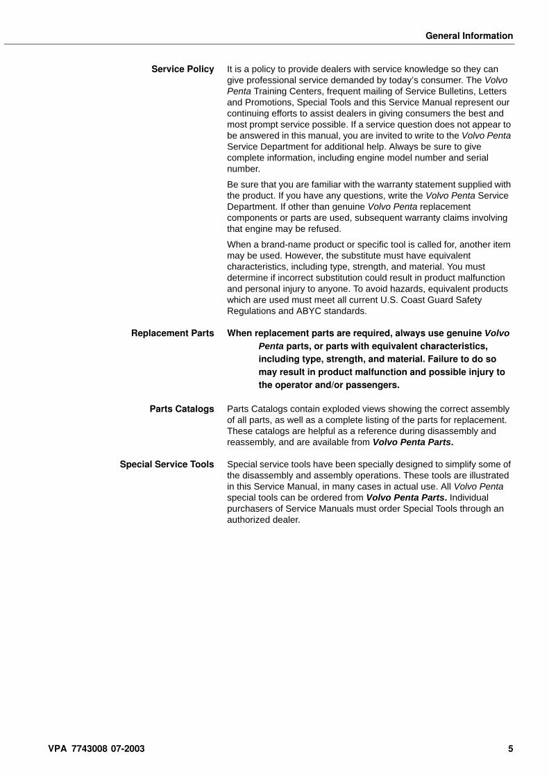
Occasionally check oil level in sterndrive. Screw dipstickfully into hole. Remove and read oil level in reference to mark ondipstick. If oil level is low, add oil through dipstick opening.
Add only enough lubricant to bring the oil level to the proper level somewhere inthe range on the dipstick.
Sterndrive Oil Capacity
Draining and Filling Sterndrive When a complete change of lubricant is required in the sterndrive, proceed as follows:
1. Place sterndrive in the run (full down) position. Place a 4 quart drain pan under lower gear case skeg to catch oil.
2. Remove oil drain plug (port side of lower gear case) and oil level dipstick (top of sterndrive). Removing dipstick vents drive to improve oil draining. Allow oil to drain completely.
34086
33836
Change Lubricant Every 100 Hoursor
Once Each seasonUse
Volvo Penta Synthetic Gearcase Lubricantor
Mobilube 1 SHC Fully Synthetic SAE 75W-90 gear lubricant
All SX Models 71oz. (2100 cc)
6 VPA 7743008 07-2003
General Information
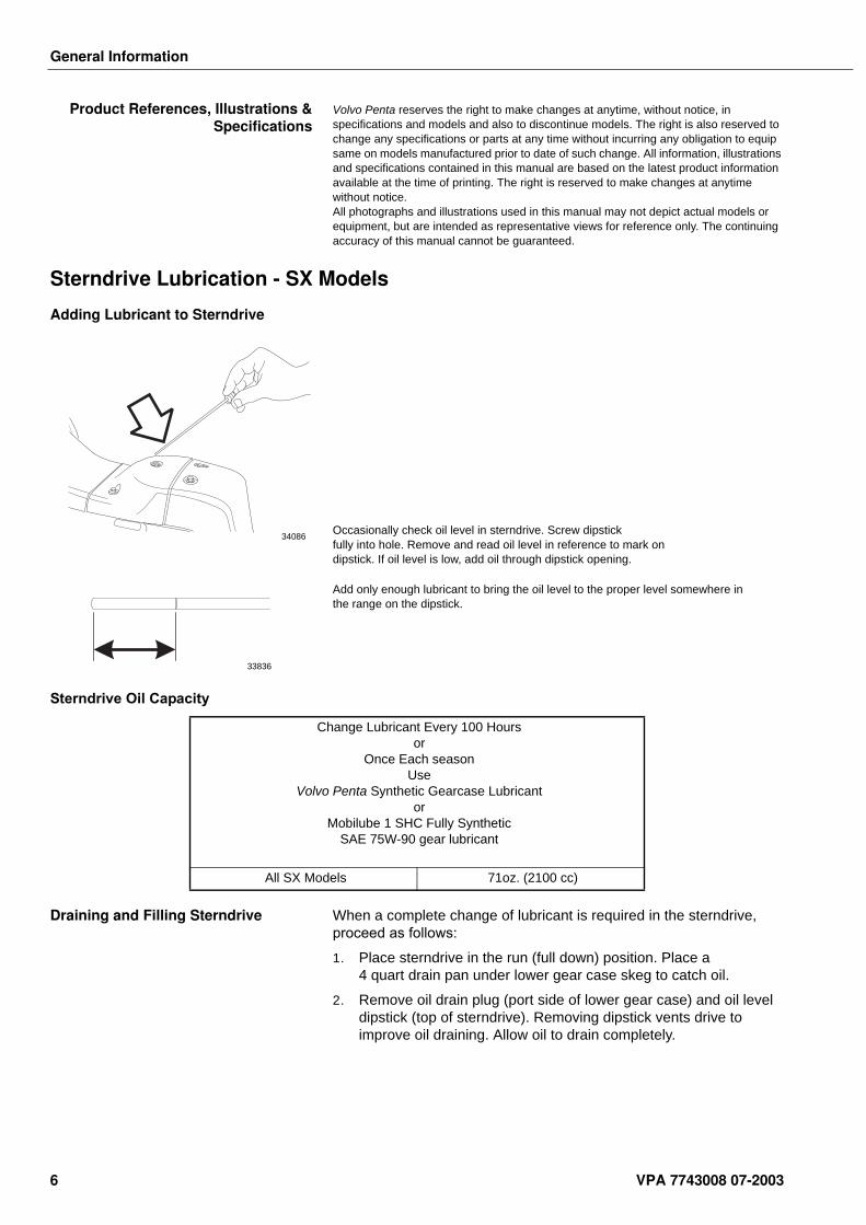
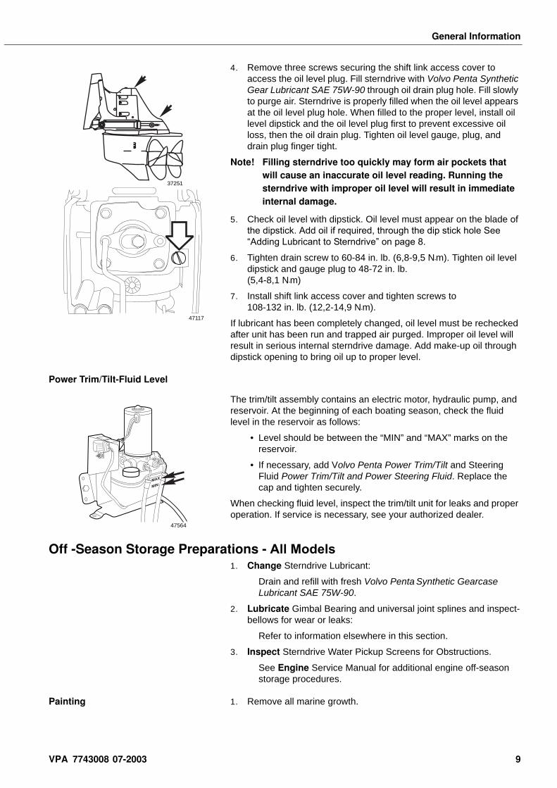
3. Remove three screws securing the shift link access cover to access the oil level plug. Fill sterndrive with Volvo Penta Synthetic Gearcase Lubricant SAE 75W-90 through oil drain plug hole. Fill slowly to purge air.
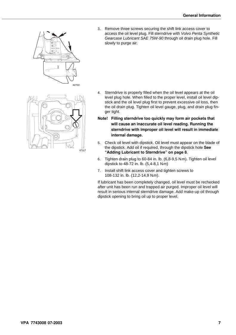
4. Sterndrive is properly filled when the oil level appears at the oil level plug hole. When filled to the proper level, install oil level dip-stick and the oil level plug first to prevent excessive oil loss, then the oil drain plug. Tighten oil level gauge, plug, and drain plug fin-ger tight.
Note! Filling sterndrive too quickly may form air pockets that will cause an inaccurate oil level reading. Running the sterndrive with improper oil level will result in immediate internal damage.
5. Check oil level with dipstick. Oil level must appear on the blade of the dipstick. Add oil if required, through the dipstick hole See “Adding Lubricant to Sterndrive” on page 8.
6. Tighten drain plug to 60-84 in. lb. (6,8-9,5 N•m). Tighten oil level dipstick to 48-72 in. lb. (5,4-8,1 N•m)
7. Install shift link access cover and tighten screws to 108-132 in. lb. (12,2-14,9 N•m).
If lubricant has been completely changed, oil level must be rechecked after unit has been run and trapped air purged. Improper oil level will result in serious internal sterndrive damage. Add make-up oil through dipstick opening to bring oil up to proper level.
VOLVO PENTA
42722
47117
VPA 7743008 07-2003 7
General Information
Sterndrive Lubrication - DP-S Models
Adding Lubricant to Sterndrive
Occasionally check oil level in sterndrive. Screw dipstick fully into hole. Remove and read oil level in reference to mark on dipstick. If oil level is low, add oil through dipstick opening.
Add only enough lubricant to bring the oil level to the proper level somewhere in the range on the dipstick.
Sterndrive Oil Capacity
Draining and Filling Sterndrive When a complete change of lubricant is required in the sterndrive, proceed as follows:
1. Remove both propellers See “Propeller Removal and Installa-tion - DP-S Models” on page 263.
2. Place sterndrive in the run (full down) position. Place a 4 quart drain pan under lower gear case skeg to catch oil.
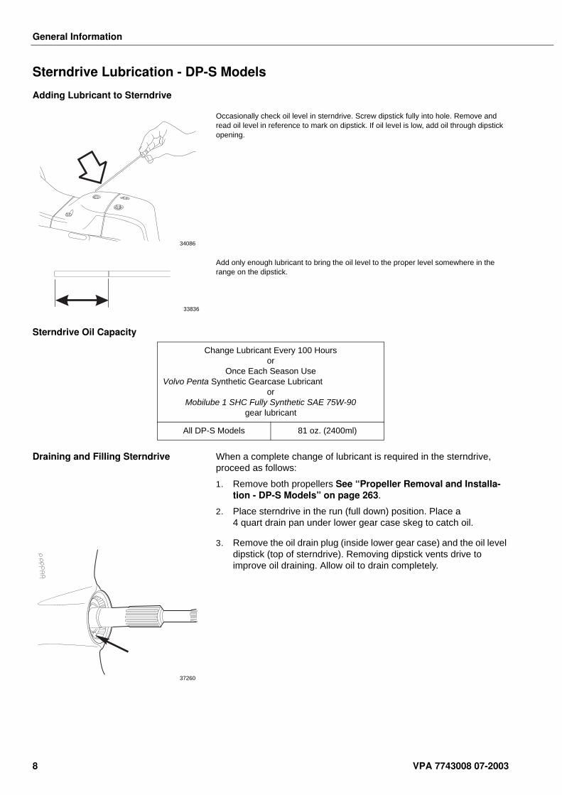
3. Remove the oil drain plug (inside lower gear case) and the oil level dipstick (top of sterndrive). Removing dipstick vents drive to improve oil draining. Allow oil to drain completely.
34086
33836
Change Lubricant Every 100 Hoursor
Once Each Season UseVolvo Penta Synthetic Gearcase Lubricant
orMobilube 1 SHC Fully Synthetic SAE 75W-90
gear lubricant
All DP-S Models 81 oz. (2400ml)
37260
8 VPA 7743008 07-2003
General Information
4. Remove three screws securing the shift link access cover to access the oil level plug. Fill sterndrive with Volvo Penta Synthetic Gear Lubricant SAE 75W-90 through oil drain plug hole. Fill slowly to purge air. Sterndrive is properly filled when the oil level appears at the oil level plug hole. When filled to the proper level, install oil level dipstick and the oil level plug first to prevent excessive oil loss, then the oil drain plug. Tighten oil level gauge, plug, and drain plug finger tight.
Note! Filling sterndrive too quickly may form air pockets that will cause an inaccurate oil level reading. Running the sterndrive with improper oil level will result in immediate internal damage.
5. Check oil level with dipstick. Oil level must appear on the blade of the dipstick. Add oil if required, through the dip stick hole See “Adding Lubricant to Sterndrive” on page 8.
6. Tighten drain screw to 60-84 in. lb. (6,8-9,5 N•m). Tighten oil level dipstick and gauge plug to 48-72 in. lb. (5,4-8,1 N•m)
7. Install shift link access cover and tighten screws to 108-132 in. lb. (12,2-14,9 N•m).
If lubricant has been completely changed, oil level must be rechecked after unit has been run and trapped air purged. Improper oil level will result in serious internal sterndrive damage. Add make-up oil through dipstick opening to bring oil up to proper level.
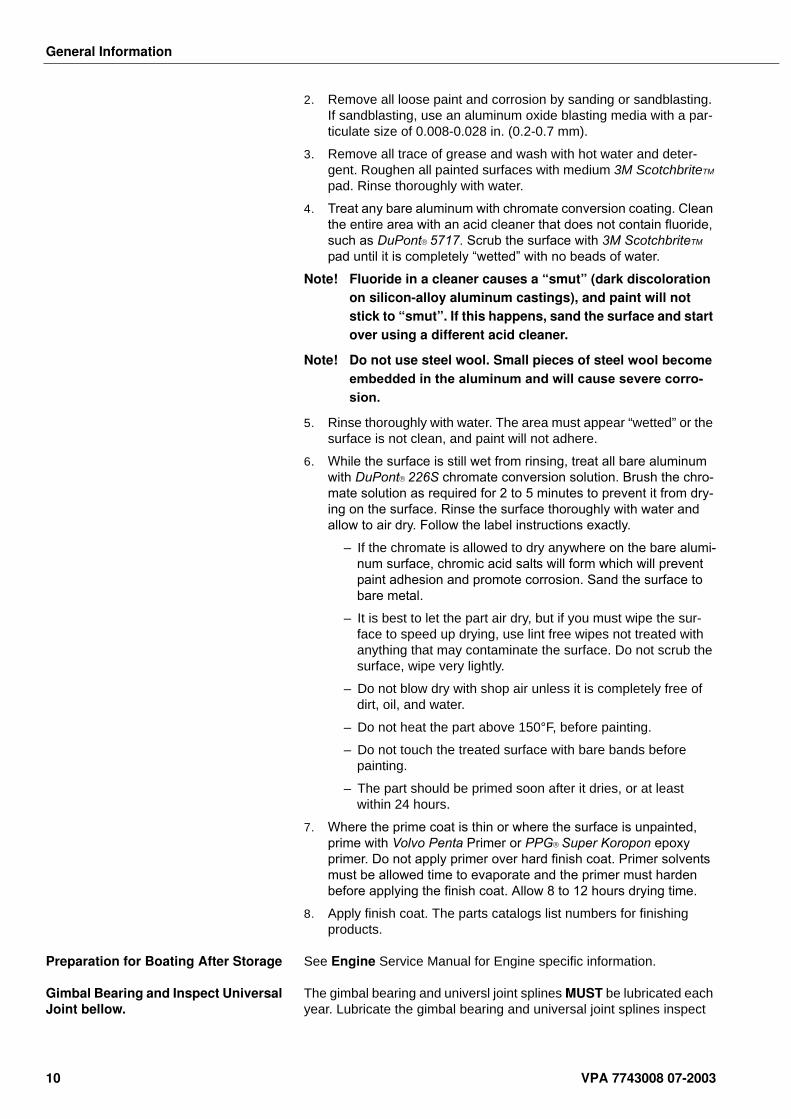
Power Trim/Tilt-Fluid Level
The trim/tilt assembly contains an electric motor, hydraulic pump, and reservoir. At the beginning of each boating season, check the fluid level in the reservoir as follows:
• Level should be between the “MIN” and “MAX” marks on the reservoir.
• If necessary, add Volvo Penta Power Trim/Tilt and Steering Fluid Power Trim/Tilt and Power Steering Fluid. Replace the cap and tighten securely.
When checking fluid level, inspect the trim/tilt unit for leaks and proper operation. If service is necessary, see your authorized dealer.
Off -Season Storage Preparations - All Models1. Change Sterndrive Lubricant:
Drain and refill with fresh Volvo Penta Synthetic Gearcase Lubricant SAE 75W-90.
2. Lubricate Gimbal Bearing and universal joint splines and inspect-bellows for wear or leaks:
Refer to information elsewhere in this section.
3. Inspect Sterndrive Water Pickup Screens for Obstructions.
See Engine Service Manual for additional engine off-season storage procedures.
Painting 1. Remove all marine growth.
37251
47117
MAX
MIN
47564
VPA 7743008 07-2003 9
General Information
2. Remove all loose paint and corrosion by sanding or sandblasting. If sandblasting, use an aluminum oxide blasting media with a par-ticulate size of 0.008-0.028 in. (0.2-0.7 mm).
3. Remove all trace of grease and wash with hot water and deter-gent. Roughen all painted surfaces with medium 3M ScotchbriteTM
pad. Rinse thoroughly with water.
4. Treat any bare aluminum with chromate conversion coating. Clean the entire area with an acid cleaner that does not contain fluoride, such as DuPont 5717. Scrub the surface with 3M ScotchbriteTM
pad until it is completely “wetted” with no beads of water.
Note! Fluoride in a cleaner causes a “smut” (dark discoloration on silicon-alloy aluminum castings), and paint will not stick to “smut”. If this happens, sand the surface and start over using a different acid cleaner.
Note! Do not use steel wool. Small pieces of steel wool become embedded in the aluminum and will cause severe corro-sion.
5. Rinse thoroughly with water. The area must appear “wetted” or the surface is not clean, and paint will not adhere.
6. While the surface is still wet from rinsing, treat all bare aluminum with DuPont 226S chromate conversion solution. Brush the chro-mate solution as required for 2 to 5 minutes to prevent it from dry-ing on the surface. Rinse the surface thoroughly with water and allow to air dry. Follow the label instructions exactly.
–If the chromate is allowed to dry anywhere on the bare alumi-num surface, chromic acid salts will form which will prevent paint adhesion and promote corrosion. Sand the surface to bare metal.
–It is best to let the part air dry, but if you must wipe the sur-face to speed up drying, use lint free wipes not treated with anything that may contaminate the surface. Do not scrub the surface, wipe very lightly.
–Do not blow dry with shop air unless it is completely free of dirt, oil, and water.
–Do not heat the part above 150°F, before painting.
–Do not touch the treated surface with bare bands before painting.
–The part should be primed soon after it dries, or at least within 24 hours.
7. Where the prime coat is thin or where the surface is unpainted, prime with Volvo Penta Primer or PPG Super Koropon epoxy primer. Do not apply primer over hard finish coat. Primer solvents must be allowed time to evaporate and the primer must harden before applying the finish coat. Allow 8 to 12 hours drying time.
8. Apply finish coat. The parts catalogs list numbers for finishing products.
Preparation for Boating After Storage See Engine Service Manual for Engine specific information.
Gimbal Bearing and Inspect Universal Joint bellow.
The gimbal bearing and universl joint splines MUST be lubricated each year. Lubricate the gimbal bearing and universal joint splines inspect
10 VPA 7743008 07-2003
General Information
the bellows when preparing your boat for off-season storage. This requires the removal of the sterndrive.
Note! Failure to lubricate the gimbal bearing, universal joint shaft splines and inspect the bellows each year will result in damage to the transom shield and sterndrive.
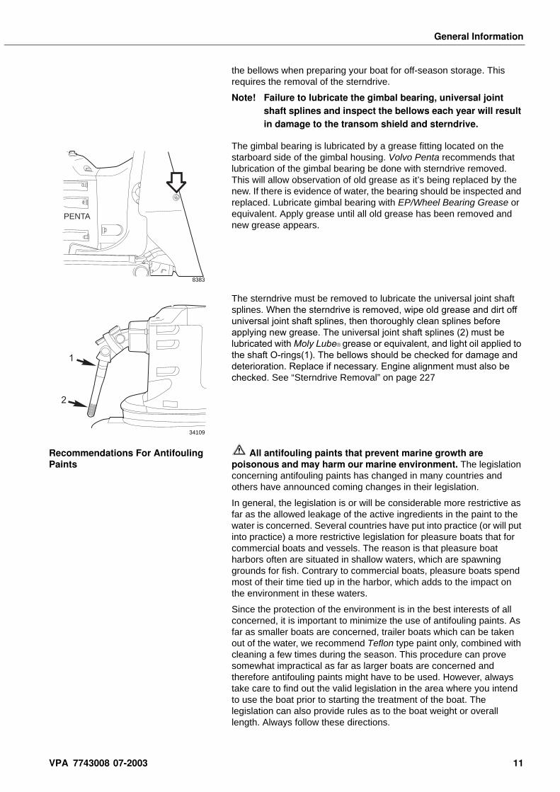
The gimbal bearing is lubricated by a grease fitting located on the starboard side of the gimbal housing. Volvo Penta recommends that lubrication of the gimbal bearing be done with sterndrive removed. This will allow observation of old grease as it’s being replaced by the new. If there is evidence of water, the bearing should be inspected and replaced. Lubricate gimbal bearing with EP/Wheel Bearing Grease or equivalent. Apply grease until all old grease has been removed and new grease appears.
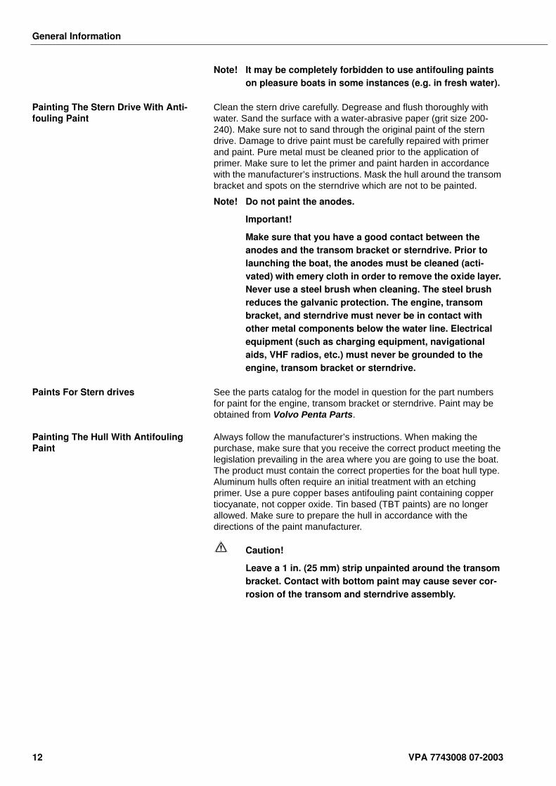
The sterndrive must be removed to lubricate the universal joint shaft splines. When the sterndrive is removed, wipe old grease and dirt off universal joint shaft splines, then thoroughly clean splines before applying new grease. The universal joint shaft splines (2) must be lubricated with Moly Lube grease or equivalent, and light oil applied to the shaft O-rings(1). The bellows should be checked for damage and deterioration. Replace if necessary. Engine alignment must also be checked. See “Sterndrive Removal” on page 227
Recommendations For Antifouling Paints
All antifouling paints that prevent marine growth are poisonous and may harm our marine environment. The legislation concerning antifouling paints has changed in many countries and others have announced coming changes in their legislation.
In general, the legislation is or will be considerable more restrictive as far as the allowed leakage of the active ingredients in the paint to the water is concerned. Several countries have put into practice (or will put into practice) a more restrictive legislation for pleasure boats that for commercial boats and vessels. The reason is that pleasure boat harbors often are situated in shallow waters, which are spawning grounds for fish. Contrary to commercial boats, pleasure boats spend most of their time tied up in the harbor, which adds to the impact on the environment in these waters.
Since the protection of the environment is in the best interests of all concerned, it is important to minimize the use of antifouling paints. As far as smaller boats are concerned, trailer boats which can be taken out of the water, we recommend Teflon type paint only, combined with cleaning a few times during the season. This procedure can prove somewhat impractical as far as larger boats are concerned and therefore antifouling paints might have to be used. However, always take care to find out the valid legislation in the area where you intend to use the boat prior to starting the treatment of the boat. The legislation can also provide rules as to the boat weight or overall length. Always follow these directions.
PENTA
8383
1
2
34109
VPA 7743008 07-2003 11
General Information
Note! It may be completely forbidden to use antifouling paints on pleasure boats in some instances (e.g. in fresh water).
Painting The Stern Drive With Anti-fouling Paint
Clean the stern drive carefully. Degrease and flush thoroughly with water. Sand the surface with a water-abrasive paper (grit size 200-240). Make sure not to sand through the original paint of the stern drive. Damage to drive paint must be carefully repaired with primer and paint. Pure metal must be cleaned prior to the application of primer. Make sure to let the primer and paint harden in accordance with the manufacturer’s instructions. Mask the hull around the transom bracket and spots on the sterndrive which are not to be painted.
Note! Do not paint the anodes.
Important!
Make sure that you have a good contact between the anodes and the transom bracket or sterndrive. Prior to launching the boat, the anodes must be cleaned (acti-vated) with emery cloth in order to remove the oxide layer. Never use a steel brush when cleaning. The steel brush reduces the galvanic protection. The engine, transom bracket, and sterndrive must never be in contact with other metal components below the water line. Electrical equipment (such as charging equipment, navigational aids, VHF radios, etc.) must never be grounded to the engine, transom bracket or sterndrive.
Paints For Stern drives See the parts catalog for the model in question for the part numbers for paint for the engine, transom bracket or sterndrive. Paint may be obtained from Volvo Penta Parts.
Painting The Hull With Antifouling Paint
Always follow the manufacturer’s instructions. When making the purchase, make sure that you receive the correct product meeting the legislation prevailing in the area where you are going to use the boat. The product must contain the correct properties for the boat hull type. Aluminum hulls often require an initial treatment with an etching primer. Use a pure copper bases antifouling paint containing copper tiocyanate, not copper oxide. Tin based (TBT paints) are no longer allowed. Make sure to prepare the hull in accordance with the directions of the paint manufacturer.
Caution!
Leave a 1 in. (25 mm) strip unpainted around the transom bracket. Contact with bottom paint may cause sever cor-rosion of the transom and sterndrive assembly.
12 VPA 7743008 07-2003
General Information
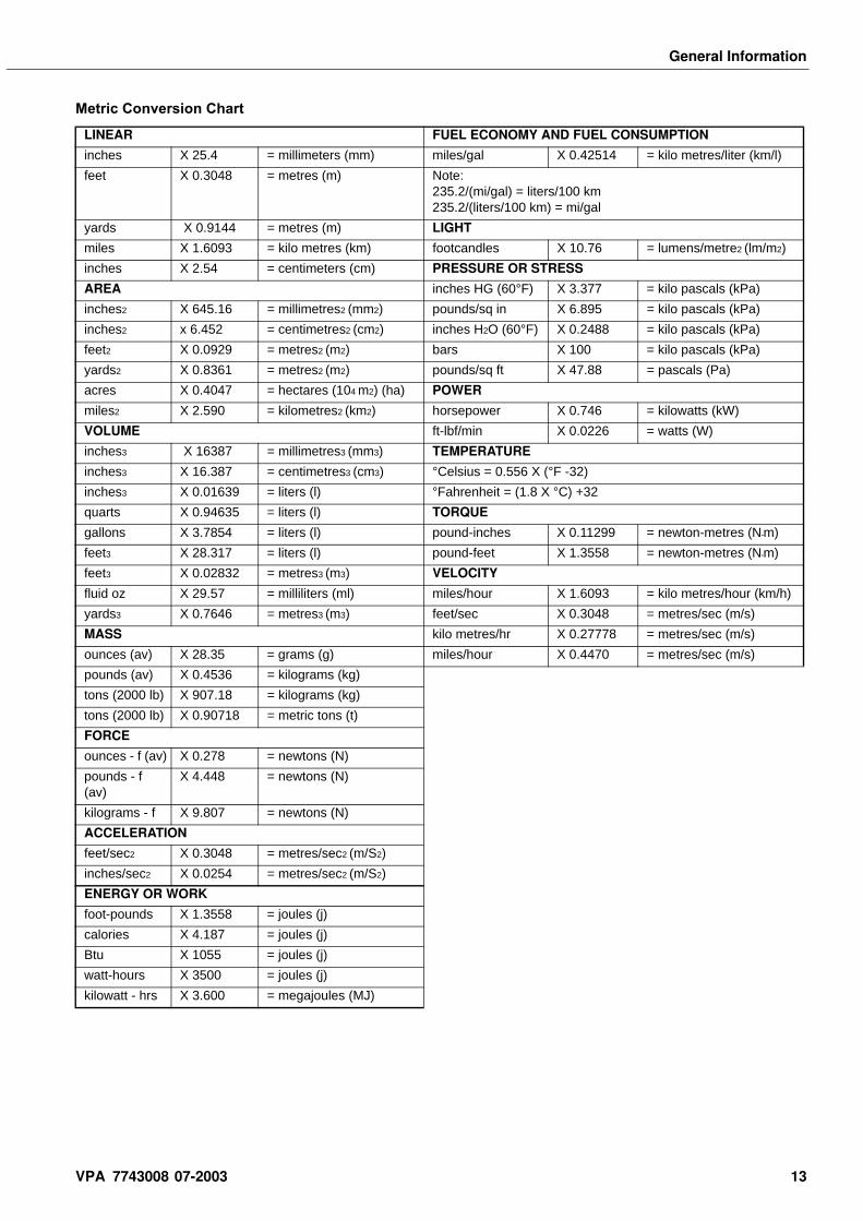
Metric Conversion Chart
LINEAR FUEL ECONOMY AND FUEL CONSUMPTION
inches X 25.4 = millimeters (mm) miles/gal X 0.42514 = kilo metres/liter (km/l)
feet X 0.3048 = metres (m) Note: 235.2/(mi/gal) = liters/100 km235.2/(liters/100 km) = mi/gal
yards X 0.9144 = metres (m) LIGHT
miles X 1.6093 = kilo metres (km) footcandles X 10.76 = lumens/metre2 (lm/m2)
inches X 2.54 = centimeters (cm) PRESSURE OR STRESS
AREA inches HG (60°F) X 3.377 = kilo pascals (kPa)
inches2 X 645.16 = millimetres2 (mm2) pounds/sq in X 6.895 = kilo pascals (kPa)
inches2 x 6.452 = centimetres2 (cm2) inches H2O (60°F) X 0.2488 = kilo pascals (kPa)
feet2 X 0.0929 = metres2 (m2) bars X 100 = kilo pascals (kPa)
yards2 X 0.8361 = metres2 (m2) pounds/sq ft X 47.88 = pascals (Pa)
acres X 0.4047 = hectares (104 m2) (ha) POWER
miles2 X 2.590 = kilometres2 (km2) horsepower X 0.746 = kilowatts (kW)
VOLUME ft-lbf/min X 0.0226 = watts (W)
inches3 X 16387 = millimetres3 (mm3) TEMPERATURE
inches3 X 16.387 = centimetres3 (cm3) °Celsius = 0.556 X (°F -32)
inches3 X 0.01639 = liters (l) °Fahrenheit = (1.8 X °C) +32
quarts X 0.94635 = liters (l) TORQUE
gallons X 3.7854 = liters (l) pound-inches X 0.11299 = newton-metres (N•m)
feet3 X 28.317 = liters (l) pound-feet X 1.3558 = newton-metres (N•m)
feet3 X 0.02832 = metres3 (m3) VELOCITY
fluid oz X 29.57 = milliliters (ml) miles/hour X 1.6093 = kilo metres/hour (km/h)
yards3 X 0.7646 = metres3 (m3) feet/sec X 0.3048 = metres/sec (m/s)
MASS kilo metres/hr X 0.27778 = metres/sec (m/s)
ounces (av) X 28.35 = grams (g) miles/hour X 0.4470 = metres/sec (m/s)
pounds (av) X 0.4536 = kilograms (kg)
tons (2000 lb) X 907.18 = kilograms (kg)
tons (2000 lb) X 0.90718 = metric tons (t)
FORCE
ounces - f (av) X 0.278 = newtons (N)
pounds - f (av)
X 4.448 = newtons (N)
kilograms - f X 9.807 = newtons (N)
ACCELERATION
feet/sec2 X 0.3048 = metres/sec2 (m/S2)
inches/sec2 X 0.0254 = metres/sec2 (m/S2)
ENERGY OR WORK
foot-pounds X 1.3558 = joules (j)
calories X 4.187 = joules (j)
Btu X 1055 = joules (j)
watt-hours X 3500 = joules (j)
kilowatt - hrs X 3.600 = megajoules (MJ)
VPA 7743008 07-2003 13
General Information
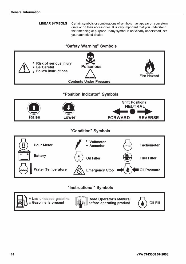
LINEAR SYMBOLS Certain symbols or combinations of symbols may appear on your stern drive or on their accessories. It is very important that you understand their meaning or purpose. If any symbol is not clearly understood, see your authorized dealer.
“Safety Warning” Symbols
“Position Indicator” Symbols
“Condition” Symbols
“Instructional” Symbols
Poisonous
Fire Hazard
Risk of serious injuryBe CarefulFollow instructions
Contents Under Pressure
Raise Lower REVERSEFORWARD
Shift Positions
NEUTRAL
Hour Meter
Battery
Water Temperature
Oil Filter
Emergency Stop
VoltmeterAmmeter r/min
Oil Pressure
Fuel Filter
Tachometer
Oil FillRead Operator's Manuralbefore operating product
Use unleaded gasolineGasoline is presentPbPb
- +
14 VPA 7743008 07-2003
General Information
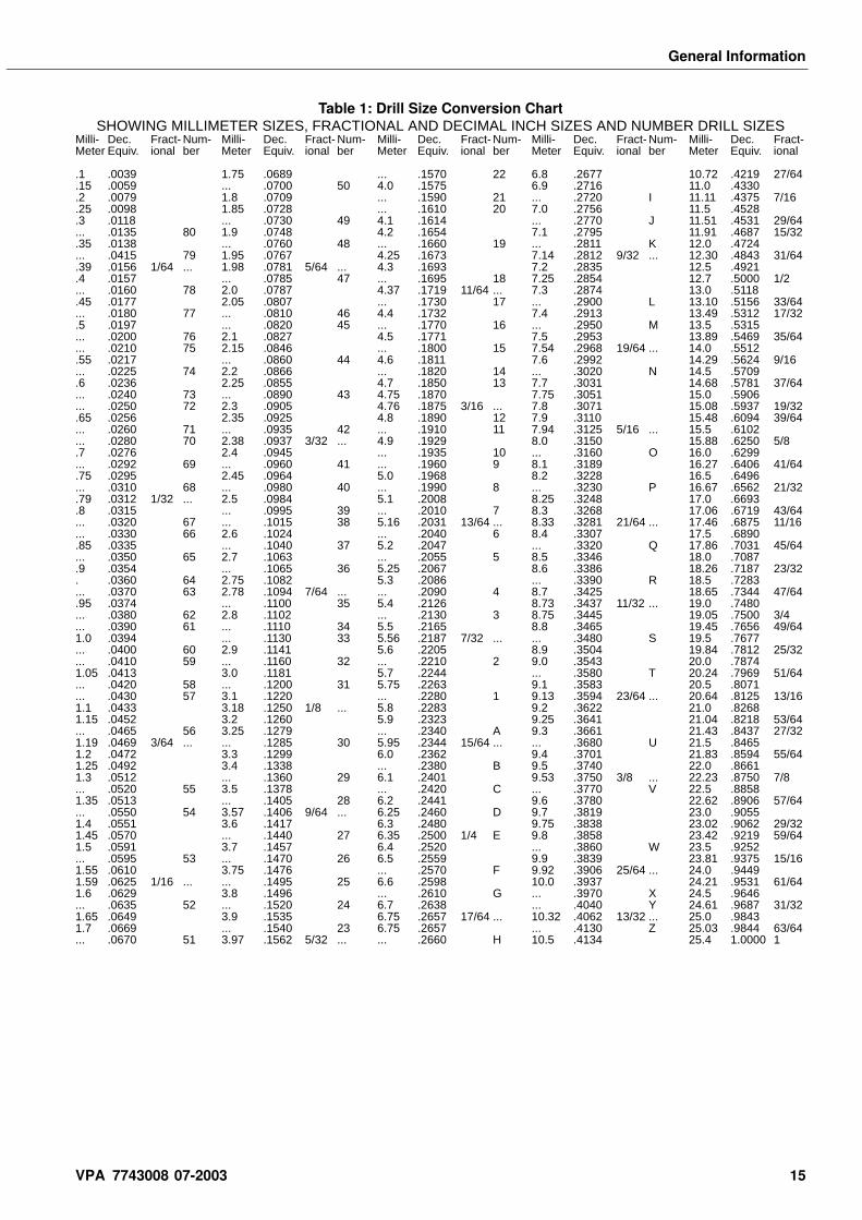
Table 1: Drill Size Conversion ChartSHOWING MILLIMETER SIZES, FRACTIONAL AND DECIMAL INCH SIZES AND NUMBER DRILL SIZES
Milli- Dec. Fract- Num- Milli- Dec. Fract- Num- Milli- Dec. Fract- Num- Milli- Dec. Fract- Num- Milli- Dec. Fract-Meter Equiv. ional ber Meter Equiv. ional ber Meter Equiv. ional ber Meter Equiv. ional ber Meter Equiv. ional
.1 .0039 1.75 .0689 ... .1570 22 6.8 .2677 10.72 .4219 27/64
.15 .0059 ... .0700 50 4.0 .1575 6.9 .2716 11.0 .4330
.2 .0079 1.8 .0709 ... .1590 21 ... .2720 I 11.11 .4375 7/16
.25 .0098 1.85 .0728 ... .1610 20 7.0 .2756 11.5 .4528
.3 .0118 ... .0730 49 4.1 .1614 ... .2770 J 11.51 .4531 29/64
... .0135 80 1.9 .0748 4.2 .1654 7.1 .2795 11.91 .4687 15/32
.35 .0138 ... .0760 48 ... .1660 19 ... .2811 K 12.0 .4724
... .0415 79 1.95 .0767 4.25 .1673 7.14 .2812 9/32 ... 12.30 .4843 31/64
.39 .0156 1/64 ... 1.98 .0781 5/64 ... 4.3 .1693 7.2 .2835 12.5 .4921
.4 .0157 ... .0785 47 ... .1695 18 7.25 .2854 12.7 .5000 1/2
... .0160 78 2.0 .0787 4.37 .1719 11/64 ... 7.3 .2874 13.0 .5118
.45 .0177 2.05 .0807 ... .1730 17 ... .2900 L 13.10 .5156 33/64
... .0180 77 ... .0810 46 4.4 .1732 7.4 .2913 13.49 .5312 17/32
.5 .0197 ... .0820 45 ... .1770 16 ... .2950 M 13.5 .5315
... .0200 76 2.1 .0827 4.5 .1771 7.5 .2953 13.89 .5469 35/64
... .0210 75 2.15 .0846 ... .1800 15 7.54 .2968 19/64 ... 14.0 .5512
.55 .0217 ... .0860 44 4.6 .1811 7.6 .2992 14.29 .5624 9/16
... .0225 74 2.2 .0866 ... .1820 14 ... .3020 N 14.5 .5709
.6 .0236 2.25 .0855 4.7 .1850 13 7.7 .3031 14.68 .5781 37/64
... .0240 73 ... .0890 43 4.75 .1870 7.75 .3051 15.0 .5906
... .0250 72 2.3 .0905 4.76 .1875 3/16 ... 7.8 .3071 15.08 .5937 19/32
.65 .0256 2.35 .0925 4.8 .1890 12 7.9 .3110 15.48 .6094 39/64
... .0260 71 ... .0935 42 ... .1910 11 7.94 .3125 5/16 ... 15.5 .6102
... .0280 70 2.38 .0937 3/32 ... 4.9 .1929 8.0 .3150 15.88 .6250 5/8
.7 .0276 2.4 .0945 ... .1935 10 ... .3160 O 16.0 .6299
... .0292 69 ... .0960 41 ... .1960 9 8.1 .3189 16.27 .6406 41/64
.75 .0295 2.45 .0964 5.0 .1968 8.2 .3228 16.5 .6496
... .0310 68 ... .0980 40 ... .1990 8 ... .3230 P 16.67 .6562 21/32
.79 .0312 1/32 ... 2.5 .0984 5.1 .2008 8.25 .3248 17.0 .6693
.8 .0315 ... .0995 39 ... .2010 7 8.3 .3268 17.06 .6719 43/64
... .0320 67 ... .1015 38 5.16 .2031 13/64 ... 8.33 .3281 21/64 ... 17.46 .6875 11/16
... .0330 66 2.6 .1024 ... .2040 6 8.4 .3307 17.5 .6890
.85 .0335 ... .1040 37 5.2 .2047 ... .3320 Q 17.86 .7031 45/64
... .0350 65 2.7 .1063 ... .2055 5 8.5 .3346 18.0 .7087
.9 .0354 ... .1065 36 5.25 .2067 8.6 .3386 18.26 .7187 23/32
. .0360 64 2.75 .1082 5.3 .2086 ... .3390 R 18.5 .7283
... .0370 63 2.78 .1094 7/64 ... ... .2090 4 8.7 .3425 18.65 .7344 47/64
.95 .0374 ... .1100 35 5.4 .2126 8.73 .3437 11/32 ... 19.0 .7480
... .0380 62 2.8 .1102 ... .2130 3 8.75 .3445 19.05 .7500 3/4
... .0390 61 ... .1110 34 5.5 .2165 8.8 .3465 19.45 .7656 49/641.0 .0394 ... .1130 33 5.56 .2187 7/32 ... ... .3480 S 19.5 .7677... .0400 60 2.9 .1141 5.6 .2205 8.9 .3504 19.84 .7812 25/32... .0410 59 ... .1160 32 ... .2210 2 9.0 .3543 20.0 .78741.05 .0413 3.0 .1181 5.7 .2244 ... .3580 T 20.24 .7969 51/64... .0420 58 ... .1200 31 5.75 .2263 9.1 .3583 20.5 .8071... .0430 57 3.1 .1220 ... .2280 1 9.13 .3594 23/64 ... 20.64 .8125 13/161.1 .0433 3.18 .1250 1/8 ... 5.8 .2283 9.2 .3622 21.0 .82681.15 .0452 3.2 .1260 5.9 .2323 9.25 .3641 21.04 .8218 53/64... .0465 56 3.25 .1279 ... .2340 A 9.3 .3661 21.43 .8437 27/321.19 .0469 3/64 ... ... .1285 30 5.95 .2344 15/64 ... ... .3680 U 21.5 .84651.2 .0472 3.3 .1299 6.0 .2362 9.4 .3701 21.83 .8594 55/641.25 .0492 3.4 .1338 ... .2380 B 9.5 .3740 22.0 .86611.3 .0512 ... .1360 29 6.1 .2401 9.53 .3750 3/8 ... 22.23 .8750 7/8... .0520 55 3.5 .1378 ... .2420 C ... .3770 V 22.5 .88581.35 .0513 ... .1405 28 6.2 .2441 9.6 .3780 22.62 .8906 57/64... .0550 54 3.57 .1406 9/64 ... 6.25 .2460 D 9.7 .3819 23.0 .90551.4 .0551 3.6 .1417 6.3 .2480 9.75 .3838 23.02 .9062 29/321.45 .0570 ... .1440 27 6.35 .2500 1/4 E 9.8 .3858 23.42 .9219 59/641.5 .0591 3.7 .1457 6.4 .2520 ... .3860 W 23.5 .9252... .0595 53 ... .1470 26 6.5 .2559 9.9 .3839 23.81 .9375 15/161.55 .0610 3.75 .1476 ... .2570 F 9.92 .3906 25/64 ... 24.0 .94491.59 .0625 1/16 ... ... .1495 25 6.6 .2598 10.0 .3937 24.21 .9531 61/641.6 .0629 3.8 .1496 ... .2610 G ... .3970 X 24.5 .9646... .0635 52 ... .1520 24 6.7 .2638 ... .4040 Y 24.61 .9687 31/321.65 .0649 3.9 .1535 6.75 .2657 17/64 ... 10.32 .4062 13/32 ... 25.0 .98431.7 .0669 ... .1540 23 6.75 .2657 ... .4130 Z 25.03 .9844 63/64... .0670 51 3.97 .1562 5/32 ... ... .2660 H 10.5 .4134 25.4 1.0000 1
VPA 7743008 07-2003 15
General Information
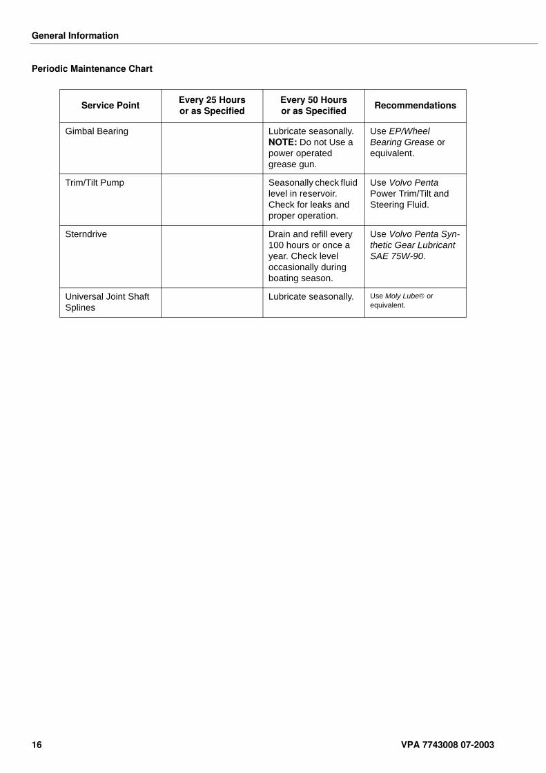
Periodic Maintenance Chart
Service PointEvery 25 Hours or as Specified
Every 50 Hoursor as Specified
Recommendations
Gimbal Bearing Lubricate seasonally. NOTE: Do not Use a power operated grease gun.
Use EP/Wheel Bearing Grease or equivalent.
Trim/Tilt Pump Seasonally check fluid level in reservoir. Check for leaks and proper operation.
Use Volvo Penta Power Trim/Tilt and Steering Fluid.
Sterndrive Drain and refill every 100 hours or once a year. Check level occasionally during boating season.
Use Volvo Penta Syn-thetic Gear Lubricant SAE 75W-90.
Universal Joint Shaft Splines
Lubricate seasonally. Use Moly Lube or equivalent.
16 VPA 7743008 07-2003
Transom Shield Assembly - SX-M
Transom Shield Assembly - SX-MTable of Contents Special Tools . . . . . . . . . . . . . . . . . . . . . . . . . . . . . . . . . . . . . . 18
Trim/Tilt Cylinder Removal . . . . . . . . . . . . . . . . . . . . . . . . . . 18Trim/Tilt Cylinder Installation . . . . . . . . . . . . . . . . . . . . . . . . 20Pivot Housing Removal . . . . . . . . . . . . . . . . . . . . . . . . . . . . . 21Pivot Housing Disassembly . . . . . . . . . . . . . . . . . . . . . . . . . . 23Pivot Housing Assembly . . . . . . . . . . . . . . . . . . . . . . . . . . . . 24Pivot Housing Installation . . . . . . . . . . . . . . . . . . . . . . . . . . . 24Gimbal Ring Removal . . . . . . . . . . . . . . . . . . . . . . . . . . . . . . . 26Gimbal Ring Disassembly . . . . . . . . . . . . . . . . . . . . . . . . . . . 28Gimbal Ring Assembly . . . . . . . . . . . . . . . . . . . . . . . . . . . . . . 29Gimbal Ring Installation . . . . . . . . . . . . . . . . . . . . . . . . . . . . . 30Trim Sender Adjustment . . . . . . . . . . . . . . . . . . . . . . . . . . . . 33
Gimbal Housing Disassembly . . . . . . . . . . . . . . . . . . 34Water Hose and Bellows Removal . . . . . . . . . . . . . . . . . . . . 34Anode Replacement . . . . . . . . . . . . . . . . . . . . . . . . . . . . . . . . 34Trim Sender Removal . . . . . . . . . . . . . . . . . . . . . . . . . . . . . . . 35Water Tube Removal . . . . . . . . . . . . . . . . . . . . . . . . . . . . . . . 35Hydraulic Lines and Manifold Removal . . . . . . . . . . . . . . . . 36Steering, Gimbal Bearing and Seal Removal . . . . . . . . . . . . 37
Gimbal Housing Cleaning and Inspection . . . . . . . . 37Gimbal Housing Assembly . . . . . . . . . . . . . . . . . . . . 38
Steering Bearing, Gimbal Bearing and Seal Installation . . . 38Hydraulic Lines and Manifold Installation . . . . . . . . . . . . . . 40Trim Sender Installation . . . . . . . . . . . . . . . . . . . . . . . . . . . . . 41Water Tube Installation . . . . . . . . . . . . . . . . . . . . . . . . . . . . . 42Water Hose Installation . . . . . . . . . . . . . . . . . . . . . . . . . . . . . 43U-joint and Exhaust Bellows Installation . . . . . . . . . . . . . . . 43
Gimbal Housing Removal . . . . . . . . . . . . . . . . . . . . . 44Shift Cable Sleeve Replacement . . . . . . . . . . . . . . . . . . . . . . 45Transom and Exhaust Seal Replacement . . . . . . . . . . . . . . 46
Gimbal Housing Installation . . . . . . . . . . . . . . . . . . . 47Torque Specifications . . . . . . . . . . . . . . . . . . . . . . . . 50
Sealants, Lubricants, and Adhesives . . . . . . . . . . . . . . . . . . 51Service Chart . . . . . . . . . . . . . . . . . . . . . . . . . . . . . . . 52
Safety Warnings Before working on any part of the transom shield assembly, read the section called Safety at the end of this manual.
When replacement parts are required, use genuine Volvo Penta or parts with equivalent characteristics including type, strength and material. Failure to do so may result in product malfunction and possible injury to the operator and/or passengers.
Some screw holes have special Held-Coil inserts that provide a thread-locking feature. Do not clean Heli-Coil holes with a thread tap. This will damage the Heli-Coil inserts and force their replacement.
VPA 7743008 07-2003 17
Transom Shield Assembly - SX-M
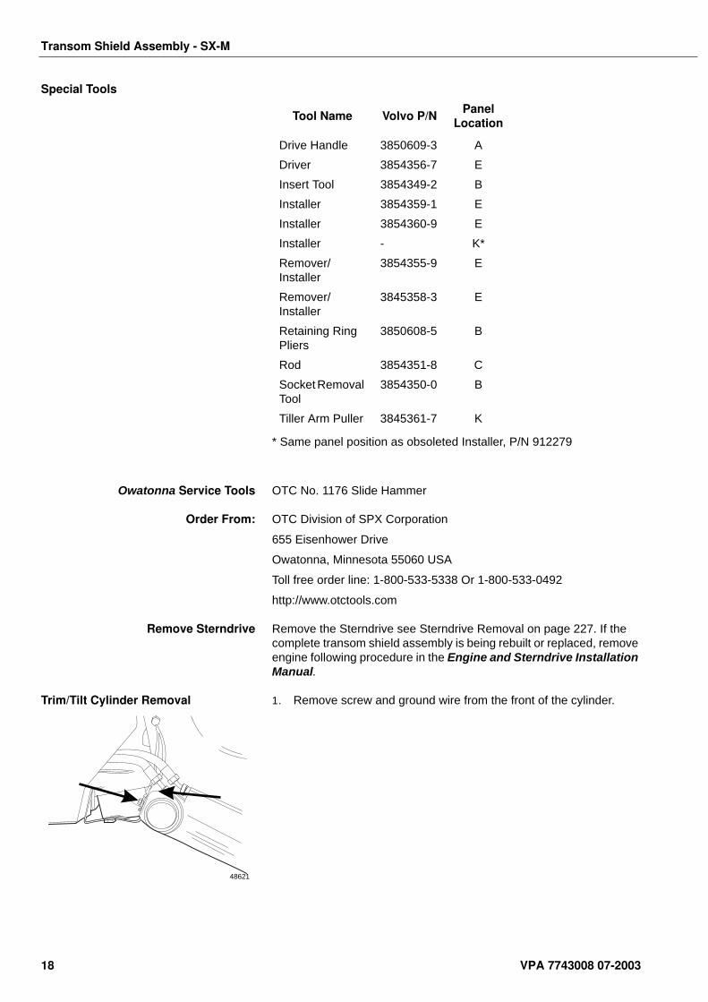
Special Tools
* Same panel position as obsoleted Installer, P/N 912279
Owatonna Service Tools OTC No. 1176 Slide Hammer
Order From: OTC Division of SPX Corporation
655 Eisenhower Drive
Owatonna, Minnesota 55060 USA
Toll free order line: 1-800-533-5338 Or 1-800-533-0492
http://www.otctools.com
Remove Sterndrive Remove the Sterndrive see Sterndrive Removal on page 227. If the complete transom shield assembly is being rebuilt or replaced, remove engine following procedure in the Engine and Sterndrive Installation Manual.
Trim/Tilt Cylinder Removal 1. Remove screw and ground wire from the front of the cylinder.
Tool Name Volvo P/NPanel
Location
Drive Handle 3850609-3 A
Driver 3854356-7 E
Insert Tool 3854349-2 B
Installer 3854359-1 E
Installer 3854360-9 E
Installer - K*
Remover/Installer
3854355-9 E
Remover/Installer
3845358-3 E
Retaining Ring Pliers
3850608-5 B
Rod 3854351-8 C
Socket Removal Tool
3854350-0 B
Tiller Arm Puller 3845361-7 K
48621
18 VPA 7743008 07-2003
Transom Shield Assembly - SX-M
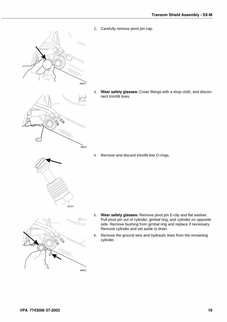
2. Carefully remove pivot pin cap.
3. Wear safety glasses: Cover fittings with a shop cloth, and discon-nect trim/tilt lines.
4. Remove and discard trim/tilt line O-rings.
5. Wear safety glasses: Remove pivot pin E-clip and flat washer. Pull pivot pin out of cylinder, gimbal ring, and cylinder on opposite side. Remove bushing from gimbal ring and replace if necessary. Remove cylinder and set aside to drain.
6. Remove the ground wire and hydraulic lines from the remaining cylinder.
48622
48624
20707
48625
VPA 7743008 07-2003 19
Transom Shield Assembly - SX-M
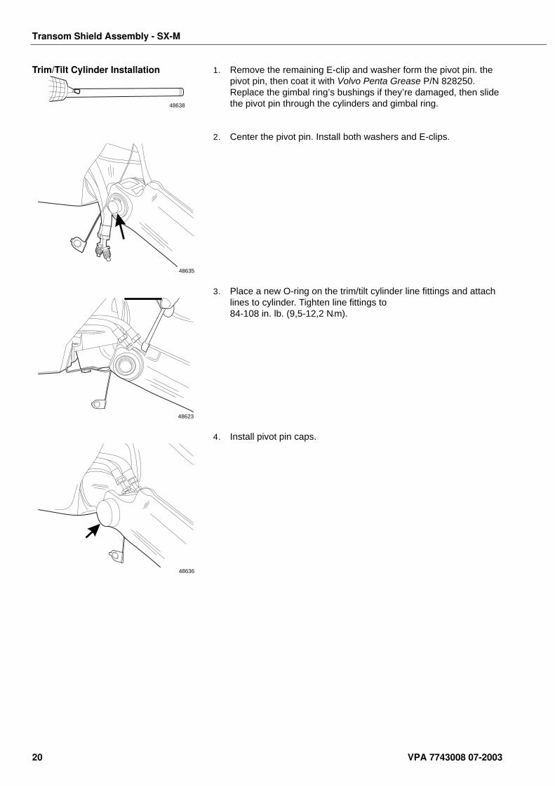
Trim/Tilt Cylinder Installation 1. Remove the remaining E-clip and washer form the pivot pin. the pivot pin, then coat it with Volvo Penta Grease P/N 828250. Replace the gimbal ring’s bushings if they’re damaged, then slide the pivot pin through the cylinders and gimbal ring.
2. Center the pivot pin. Install both washers and E-clips.
3. Place a new O-ring on the trim/tilt cylinder line fittings and attach lines to cylinder. Tighten line fittings to 84-108 in. lb. (9,5-12,2 N•m).
4. Install pivot pin caps.
48638
48635
48623
48636
20 VPA 7743008 07-2003
Transom Shield Assembly - SX-M
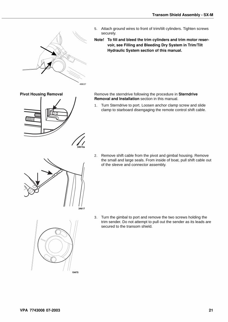
5. Attach ground wires to front of trim/tilt cylinders. Tighten screws securely.
Note! To fill and bleed the trim cylinders and trim motor reser-voir, see Filling and Bleeding Dry System in Trim/Tilt Hydraulic System section of this manual.
Pivot Housing Removal Remove the sterndrive following the procedure in Sterndrive Removal and Installation section in this manual.
1. Turn Sterndrive to port. Loosen anchor clamp screw and slide clamp to starboard disengaging the remote control shift cable.
2. Remove shift cable from the pivot and gimbal housing. Remove the small and large seals. From inside of boat, pull shift cable out of the sleeve and connector assembly.
3. Turn the gimbal to port and remove the two screws holding the trim sender. Do not attempt to pull out the sender as its leads are secured to the transom shield.
48637
34616a
34617
19475
VPA 7743008 07-2003 21
Transom Shield Assembly - SX-M
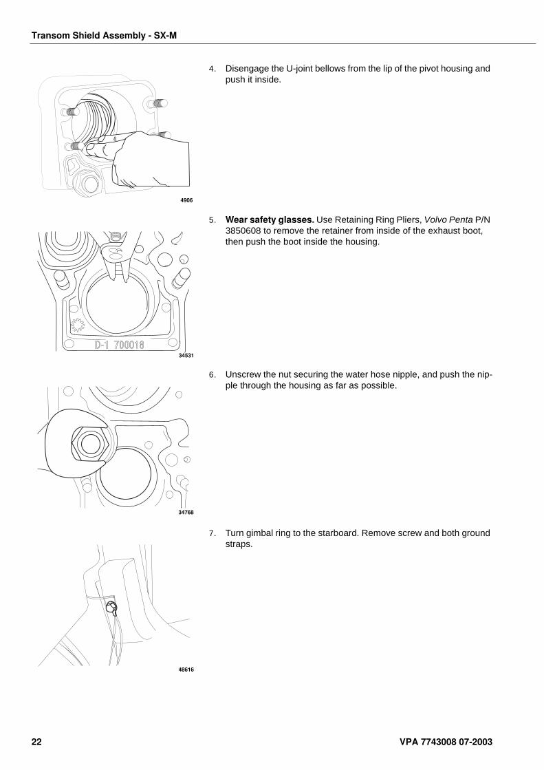
4. Disengage the U-joint bellows from the lip of the pivot housing and push it inside.
5. Wear safety glasses. Use Retaining Ring Pliers, Volvo Penta P/N 3850608 to remove the retainer from inside of the exhaust boot, then push the boot inside the housing.
6. Unscrew the nut securing the water hose nipple, and push the nip-ple through the housing as far as possible.
7. Turn gimbal ring to the starboard. Remove screw and both ground straps.
4906
34531
34768
48616
22 VPA 7743008 07-2003
Transom Shield Assembly - SX-M
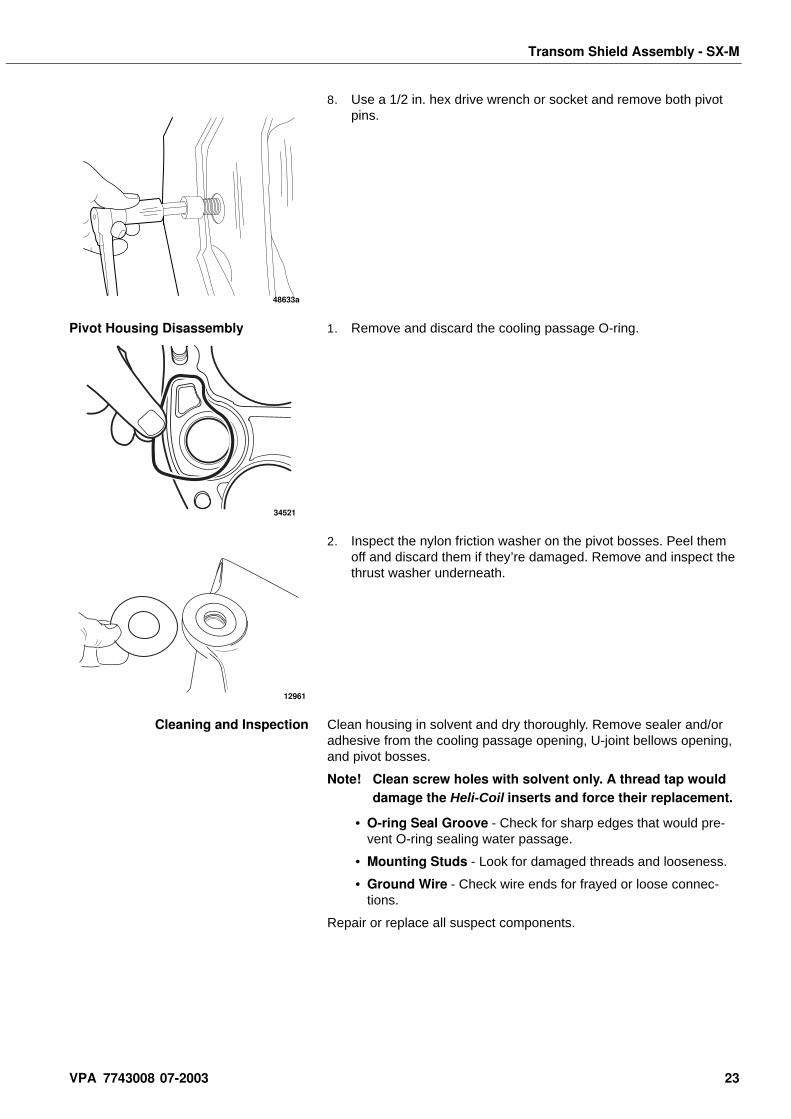
8. Use a 1/2 in. hex drive wrench or socket and remove both pivot pins.
Pivot Housing Disassembly 1. Remove and discard the cooling passage O-ring.
2. Inspect the nylon friction washer on the pivot bosses. Peel them off and discard them if they’re damaged. Remove and inspect the thrust washer underneath.
Cleaning and Inspection Clean housing in solvent and dry thoroughly. Remove sealer and/or adhesive from the cooling passage opening, U-joint bellows opening, and pivot bosses.
Note! Clean screw holes with solvent only. A thread tap would damage the Heli-Coil inserts and force their replacement.
• O-ring Seal Groove - Check for sharp edges that would pre-vent O-ring sealing water passage.
• Mounting Studs - Look for damaged threads and looseness.
• Ground Wire - Check wire ends for frayed or loose connec-tions.
Repair or replace all suspect components.
48633a
34521
12961
VPA 7743008 07-2003 23
Transom Shield Assembly - SX-M
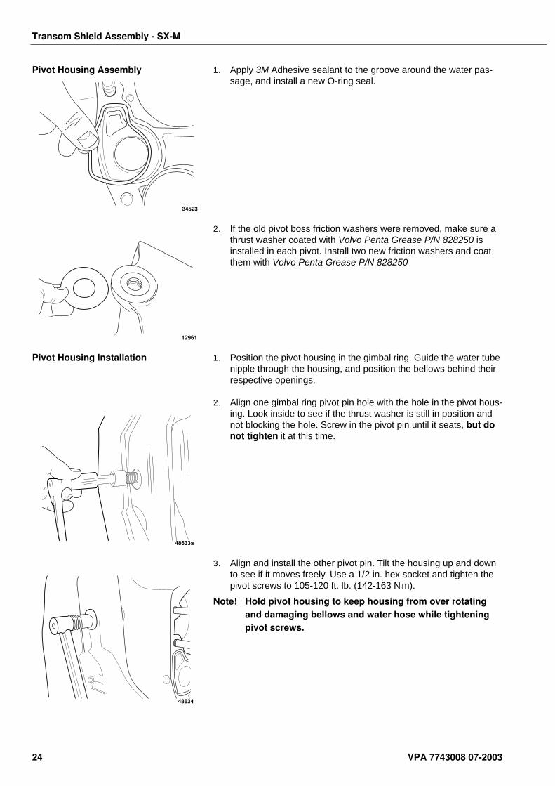
Pivot Housing Assembly 1. Apply 3M Adhesive sealant to the groove around the water pas-sage, and install a new O-ring seal.
2. If the old pivot boss friction washers were removed, make sure a thrust washer coated with Volvo Penta Grease P/N 828250 is installed in each pivot. Install two new friction washers and coat them with Volvo Penta Grease P/N 828250
Pivot Housing Installation 1. Position the pivot housing in the gimbal ring. Guide the water tube nipple through the housing, and position the bellows behind their respective openings.
2. Align one gimbal ring pivot pin hole with the hole in the pivot hous-ing. Look inside to see if the thrust washer is still in position and not blocking the hole. Screw in the pivot pin until it seats, but do not tighten it at this time.
3. Align and install the other pivot pin. Tilt the housing up and down to see if it moves freely. Use a 1/2 in. hex socket and tighten the pivot screws to 105-120 ft. lb. (142-163 N•m).
Note! Hold pivot housing to keep housing from over rotating and damaging bellows and water hose while tightening pivot screws.
34523
12961
48633a
48634
24 VPA 7743008 07-2003
Transom Shield Assembly - SX-M
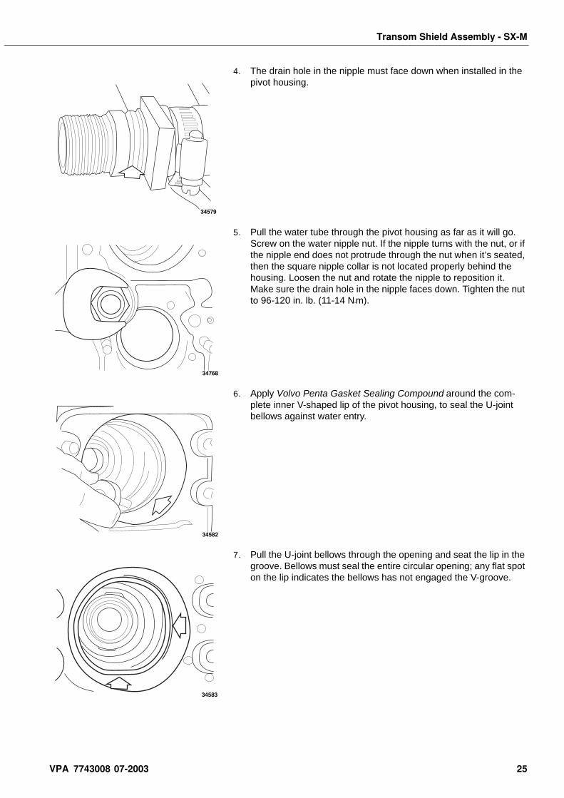
4. The drain hole in the nipple must face down when installed in the pivot housing.
5. Pull the water tube through the pivot housing as far as it will go. Screw on the water nipple nut. If the nipple turns with the nut, or if the nipple end does not protrude through the nut when it’s seated, then the square nipple collar is not located properly behind the housing. Loosen the nut and rotate the nipple to reposition it. Make sure the drain hole in the nipple faces down. Tighten the nut to 96-120 in. lb. (11-14 N•m).
6. Apply Volvo Penta Gasket Sealing Compound around the com-plete inner V-shaped lip of the pivot housing, to seal the U-joint bellows against water entry.
7. Pull the U-joint bellows through the opening and seat the lip in the groove. Bellows must seal the entire circular opening; any flat spot on the lip indicates the bellows has not engaged the V-groove.
34579
34768
34582
34583
VPA 7743008 07-2003 25
Transom Shield Assembly - SX-M
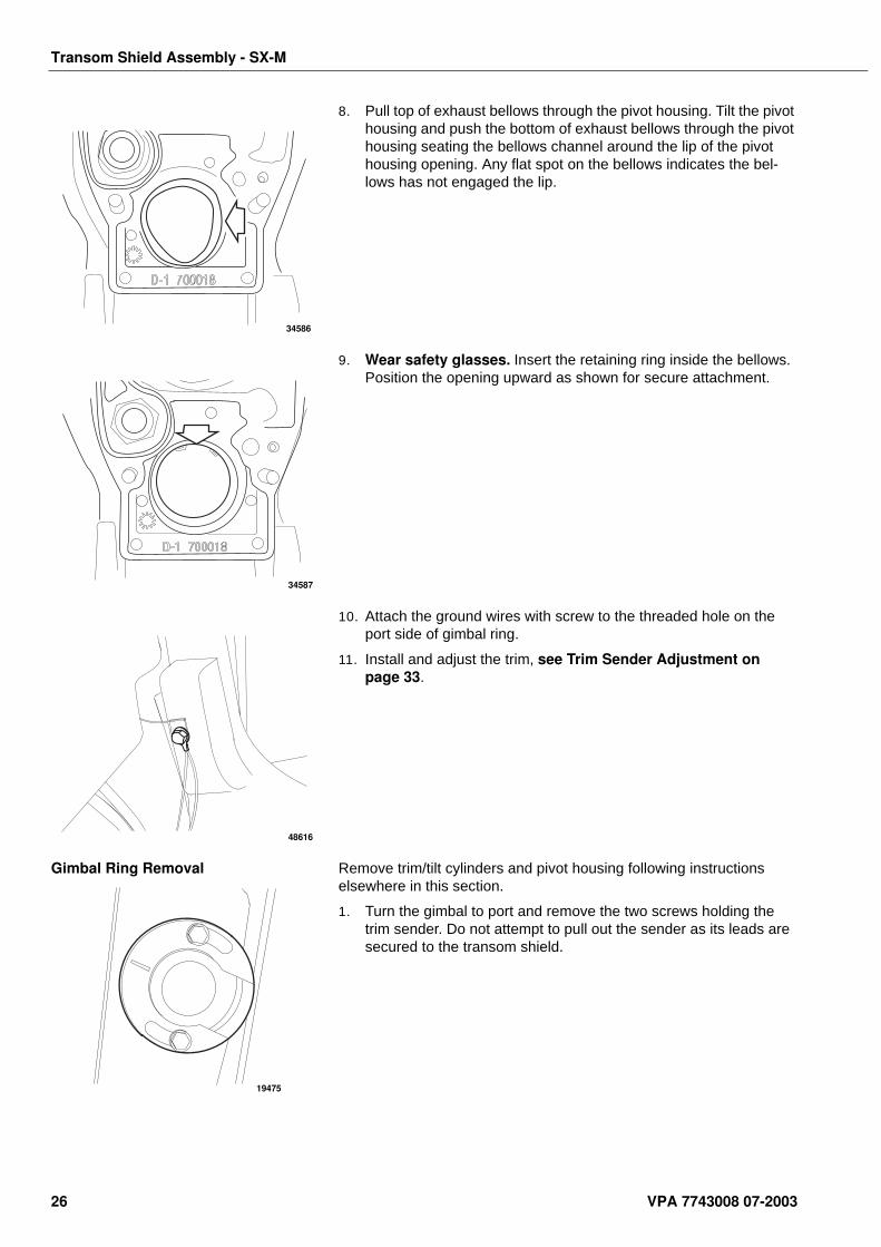
8. Pull top of exhaust bellows through the pivot housing. Tilt the pivot housing and push the bottom of exhaust bellows through the pivot housing seating the bellows channel around the lip of the pivot housing opening. Any flat spot on the bellows indicates the bel-lows has not engaged the lip.
9. Wear safety glasses. Insert the retaining ring inside the bellows. Position the opening upward as shown for secure attachment.
10. Attach the ground wires with screw to the threaded hole on the port side of gimbal ring.
11. Install and adjust the trim, see Trim Sender Adjustment on page 33.
Gimbal Ring Removal Remove trim/tilt cylinders and pivot housing following instructions elsewhere in this section.
1. Turn the gimbal to port and remove the two screws holding the trim sender. Do not attempt to pull out the sender as its leads are secured to the transom shield.
34586
34587
48616
19475
26 VPA 7743008 07-2003
Transom Shield Assembly - SX-M
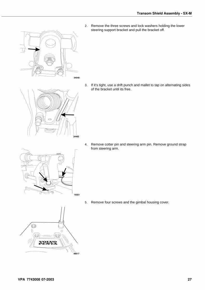
2. Remove the three screws and lock washers holding the lower steering support bracket and pull the bracket off.
3. If it’s tight, use a drift punch and mallet to tap on alternating sides of the bracket until its free.
4. Remove cotter pin and steering arm pin. Remove ground strap from steering arm.
5. Remove four screws and the gimbal housing cover.
34540
34482
19351
48617
VPA 7743008 07-2003 27
Transom Shield Assembly - SX-M
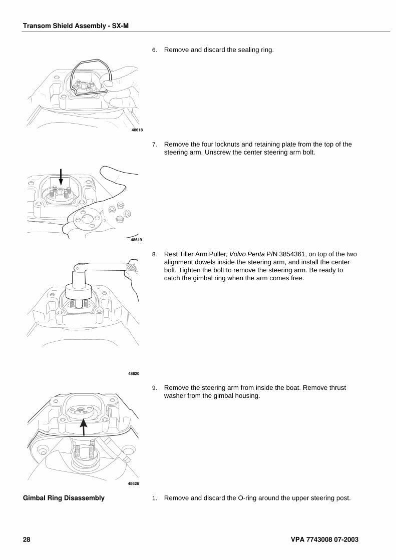
6. Remove and discard the sealing ring.
7. Remove the four locknuts and retaining plate from the top of the steering arm. Unscrew the center steering arm bolt.
8. Rest Tiller Arm Puller, Volvo Penta P/N 3854361, on top of the two alignment dowels inside the steering arm, and install the center bolt. Tighten the bolt to remove the steering arm. Be ready to catch the gimbal ring when the arm comes free.
9. Remove the steering arm from inside the boat. Remove thrust washer from the gimbal housing.
Gimbal Ring Disassembly 1. Remove and discard the O-ring around the upper steering post.
48618
48619
48620
48626
28 VPA 7743008 07-2003
Transom Shield Assembly - SX-M
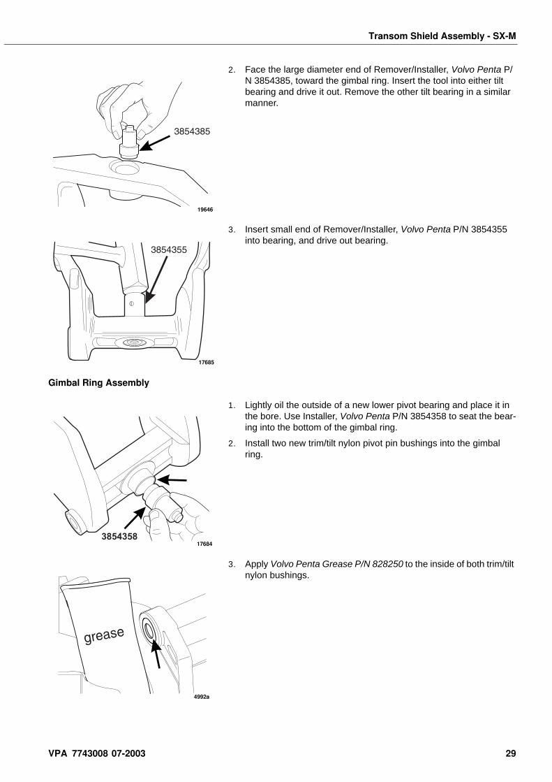
2. Face the large diameter end of Remover/Installer, Volvo Penta P/N 3854385, toward the gimbal ring. Insert the tool into either tilt bearing and drive it out. Remove the other tilt bearing in a similar manner.
3. Insert small end of Remover/Installer, Volvo Penta P/N 3854355 into bearing, and drive out bearing.
Gimbal Ring Assembly
1. Lightly oil the outside of a new lower pivot bearing and place it in the bore. Use Installer, Volvo Penta P/N 3854358 to seat the bear-ing into the bottom of the gimbal ring.
2. Install two new trim/tilt nylon pivot pin bushings into the gimbal ring.
3. Apply Volvo Penta Grease P/N 828250 to the inside of both trim/tilt nylon bushings.
19646
17685
385435817684
4992a
VPA 7743008 07-2003 29
Transom Shield Assembly - SX-M
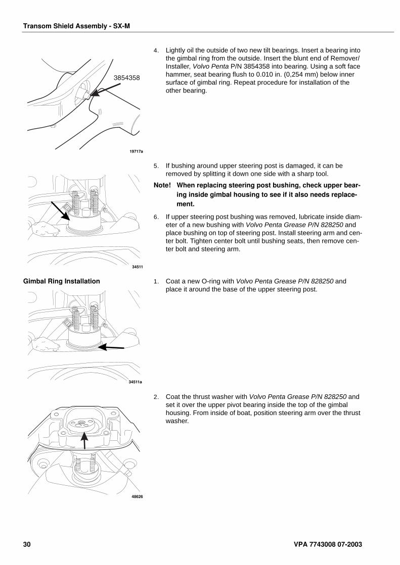
4. Lightly oil the outside of two new tilt bearings. Insert a bearing into the gimbal ring from the outside. Insert the blunt end of Remover/Installer, Volvo Penta P/N 3854358 into bearing. Using a soft face hammer, seat bearing flush to 0.010 in. (0,254 mm) below inner surface of gimbal ring. Repeat procedure for installation of the other bearing.
5. If bushing around upper steering post is damaged, it can be removed by splitting it down one side with a sharp tool.
Note! When replacing steering post bushing, check upper bear-ing inside gimbal housing to see if it also needs replace-ment.
6. If upper steering post bushing was removed, lubricate inside diam-eter of a new bushing with Volvo Penta Grease P/N 828250 and place bushing on top of steering post. Install steering arm and cen-ter bolt. Tighten center bolt until bushing seats, then remove cen-ter bolt and steering arm.
Gimbal Ring Installation 1. Coat a new O-ring with Volvo Penta Grease P/N 828250 and place it around the base of the upper steering post.
2. Coat the thrust washer with Volvo Penta Grease P/N 828250 and set it over the upper pivot bearing inside the top of the gimbal housing. From inside of boat, position steering arm over the thrust washer.
19717a
34511
34511a
48626
30 VPA 7743008 07-2003
Transom Shield Assembly - SX-M
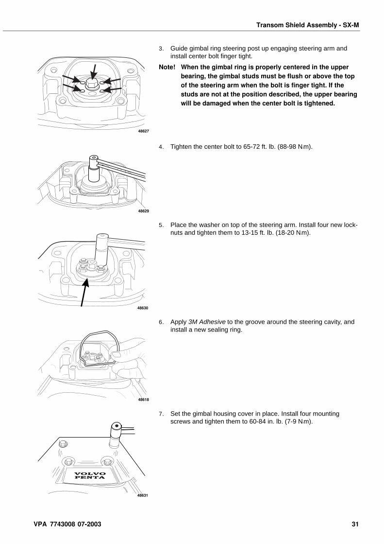
3. Guide gimbal ring steering post up engaging steering arm and install center bolt finger tight.
Note! When the gimbal ring is properly centered in the upper bearing, the gimbal studs must be flush or above the top of the steering arm when the bolt is finger tight. If the studs are not at the position described, the upper bearing will be damaged when the center bolt is tightened.
4. Tighten the center bolt to 65-72 ft. lb. (88-98 N•m).
5. Place the washer on top of the steering arm. Install four new lock-nuts and tighten them to 13-15 ft. lb. (18-20 N•m).
6. Apply 3M Adhesive to the groove around the steering cavity, and install a new sealing ring.
7. Set the gimbal housing cover in place. Install four mounting screws and tighten them to 60-84 in. lb. (7-9 N•m).
48627
48629
48630
48618
VOLVOPENTA
48631
VPA 7743008 07-2003 31
Transom Shield Assembly - SX-M
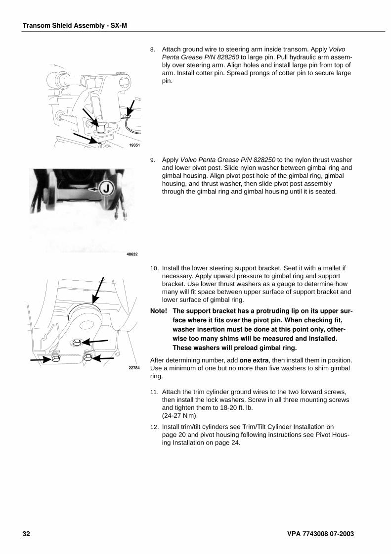
8. Attach ground wire to steering arm inside transom. Apply Volvo Penta Grease P/N 828250 to large pin. Pull hydraulic arm assem-bly over steering arm. Align holes and install large pin from top of arm. Install cotter pin. Spread prongs of cotter pin to secure large pin.
9. Apply Volvo Penta Grease P/N 828250 to the nylon thrust washer and lower pivot post. Slide nylon washer between gimbal ring and gimbal housing. Align pivot post hole of the gimbal ring, gimbal housing, and thrust washer, then slide pivot post assembly through the gimbal ring and gimbal housing until it is seated.
10. Install the lower steering support bracket. Seat it with a mallet if necessary. Apply upward pressure to gimbal ring and support bracket. Use lower thrust washers as a gauge to determine how many will fit space between upper surface of support bracket and lower surface of gimbal ring.
Note! The support bracket has a protruding lip on its upper sur-face where it fits over the pivot pin. When checking fit, washer insertion must be done at this point only, other-wise too many shims will be measured and installed. These washers will preload gimbal ring.
After determining number, add one extra, then install them in position. Use a minimum of one but no more than five washers to shim gimbal ring.
11. Attach the trim cylinder ground wires to the two forward screws, then install the lock washers. Screw in all three mounting screws and tighten them to 18-20 ft. lb. (24-27 N•m).
12. Install trim/tilt cylinders see Trim/Tilt Cylinder Installation on page 20 and pivot housing following instructions see Pivot Hous-ing Installation on page 24.
19351
48632
22784
32 VPA 7743008 07-2003
Transom Shield Assembly - SX-M
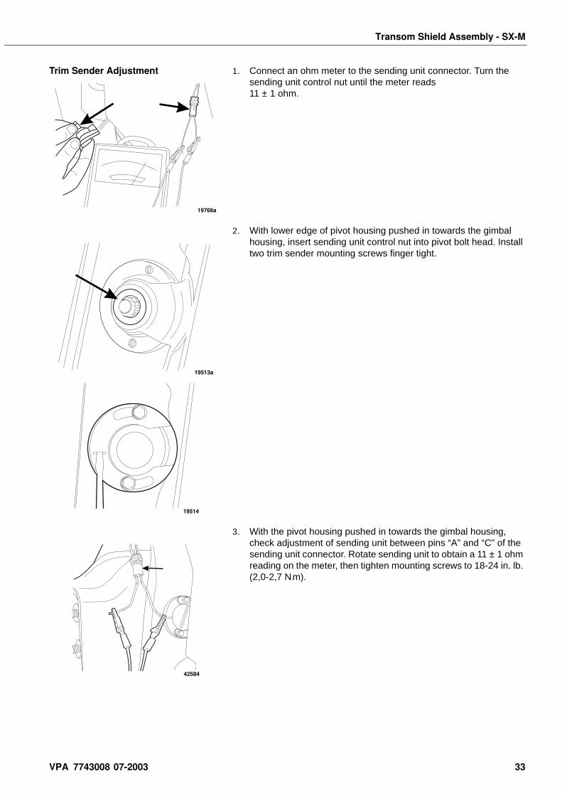
Trim Sender Adjustment 1. Connect an ohm meter to the sending unit connector. Turn the sending unit control nut until the meter reads 11 ± 1 ohm.
2. With lower edge of pivot housing pushed in towards the gimbal housing, insert sending unit control nut into pivot bolt head. Install two trim sender mounting screws finger tight.
3. With the pivot housing pushed in towards the gimbal housing, check adjustment of sending unit between pins “A” and “C” of the sending unit connector. Rotate sending unit to obtain a 11 ± 1 ohm reading on the meter, then tighten mounting screws to 18-24 in. lb. (2,0-2,7 N•m).
19766a
19513a
19514
42584
VPA 7743008 07-2003 33
Transom Shield Assembly - SX-M
Gimbal Housing DisassemblyRemove trim/tilt cylinders see Trim/Tilt Cylinder Removal on page 18, pivot housing see Pivot Housing Removal on page 21, and gimbal ring see Gimbal Ring Removal on page 26.
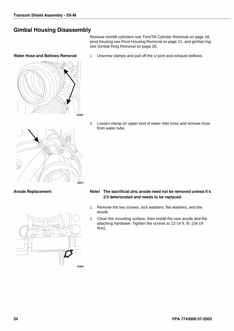
Water Hose and Bellows Removal 1. Unscrew clamps and pull off the U-joint and exhaust bellows.
2. Loosen clamp on upper end of water inlet hose and remove hose from water tube.
Anode Replacement Note! The sacrificial zinc anode need not be removed unless it’s 2/3 deteriorated and needs to be replaced.
1. Remove the two screws, lock washers, flat washers, and the anode.
2. Clean the mounting surface, then install the new anode and the attaching hardware. Tighten the screws to 12-14 ft. lb. (16-19 N•m).
34493
34471
34494
34 VPA 7743008 07-2003
Transom Shield Assembly - SX-M
Trim Sender Removal
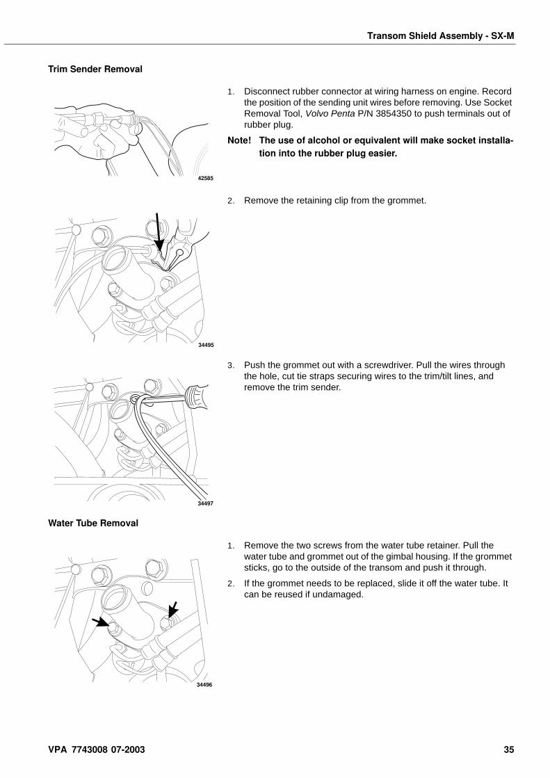
1. Disconnect rubber connector at wiring harness on engine. Record the position of the sending unit wires before removing. Use Socket Removal Tool, Volvo Penta P/N 3854350 to push terminals out of rubber plug.
Note! The use of alcohol or equivalent will make socket installa-tion into the rubber plug easier.
2. Remove the retaining clip from the grommet.
3. Push the grommet out with a screwdriver. Pull the wires through the hole, cut tie straps securing wires to the trim/tilt lines, and remove the trim sender.
Water Tube Removal
1. Remove the two screws from the water tube retainer. Pull the water tube and grommet out of the gimbal housing. If the grommet sticks, go to the outside of the transom and push it through.
2. If the grommet needs to be replaced, slide it off the water tube. It can be reused if undamaged.
42585
34495
34497
34496
VPA 7743008 07-2003 35
Transom Shield Assembly - SX-M
Hydraulic Lines and Manifold Removal
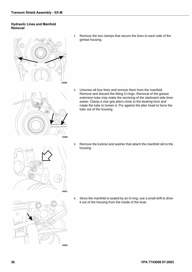
1. Remove the two clamps that secure the lines to each side of the gimbal housing.
2. Unscrew all four lines and remove them from the manifold. Remove and discard the fitting O-rings. Removal of the grease extension tube may make the servicing of the starboard side lines easier. Clamp a vise grip pliers close to the bearing bore and rotate the tube to loosen it. Pry against the plier head to force the tube out of the housing.
3. Remove the locknut and washer that attach the manifold old to the housing.
4. Since the manifold is sealed by an O-ring, use a small drift to drive it out of the housing from the inside of the boat.
34499
34500
34501
34502
36 VPA 7743008 07-2003
Transom Shield Assembly - SX-M
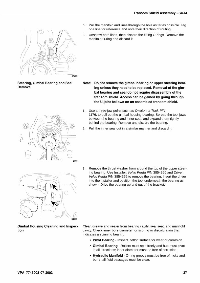
5. Pull the manifold and lines through the hole as far as possible. Tag one line for reference and note their direction of routing.
6. Unscrew both lines, then discard the fitting O-rings. Remove the manifold O-ring and discard it.
Steering, Gimbal Bearing and Seal Removal
Note! Do not remove the gimbal bearing or upper steering bear-ing unless they need to be replaced. Removal of the gim-bal bearing and seal do not require disassembly of the transom shield. Access can be gained by going through the U-joint bellows on an assembled transom shield.
1. Use a three-jaw puller such as Owatonna Tool, P/N 1176, to pull out the gimbal housing bearing. Spread the tool jaws between the bearing and inner seal, and expand them tightly behind the bearing. Remove and discard the bearing.
2. Pull the inner seal out in a similar manner and discard it.
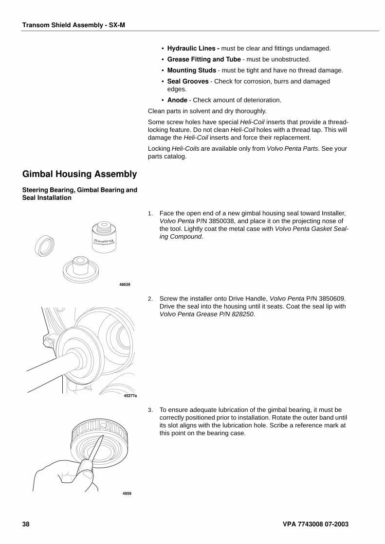
3. Remove the thrust washer from around the top of the upper steer-ing bearing. Use Installer, Volvo Penta P/N 3854360 and Driver, Volvo Penta P/N 3854356 to remove the bearing. Insert the driver into the installer and position the tool underneath the bearing as shown. Drive the bearing up and out of the bracket.
Gimbal Housing Cleaning and Inspec-tion
Clean grease and sealer from bearing cavity, seal seat, and manifold cavity. Check inner bore diameter for scoring or discoloration that indicates a spinning bearing.
• Pivot Bearing - Inspect Teflon surface for wear or corrosion.
• Gimbal Bearing - Rollers must spin freely and hub must pivot in all directions; inner diameter must be free of corrosion.
• Hydraulic Manifold - O-ring groove must be free of nicks and burrs; all fluid passages must be clear.
34503
4939
34504
VPA 7743008 07-2003 37
Transom Shield Assembly - SX-M
• Hydraulic Lines - must be clear and fittings undamaged.
• Grease Fitting and Tube - must be unobstructed.
• Mounting Studs - must be tight and have no thread damage.
• Seal Grooves - Check for corrosion, burrs and damaged edges.
• Anode - Check amount of deterioration.
Clean parts in solvent and dry thoroughly.
Some screw holes have special Heli-Coil inserts that provide a thread-locking feature. Do not clean Heli-Coil holes with a thread tap. This will damage the Heli-Coil inserts and force their replacement.
Locking Heli-Coils are available only from Volvo Penta Parts. See your parts catalog.
Gimbal Housing Assembly
Steering Bearing, Gimbal Bearing and Seal Installation
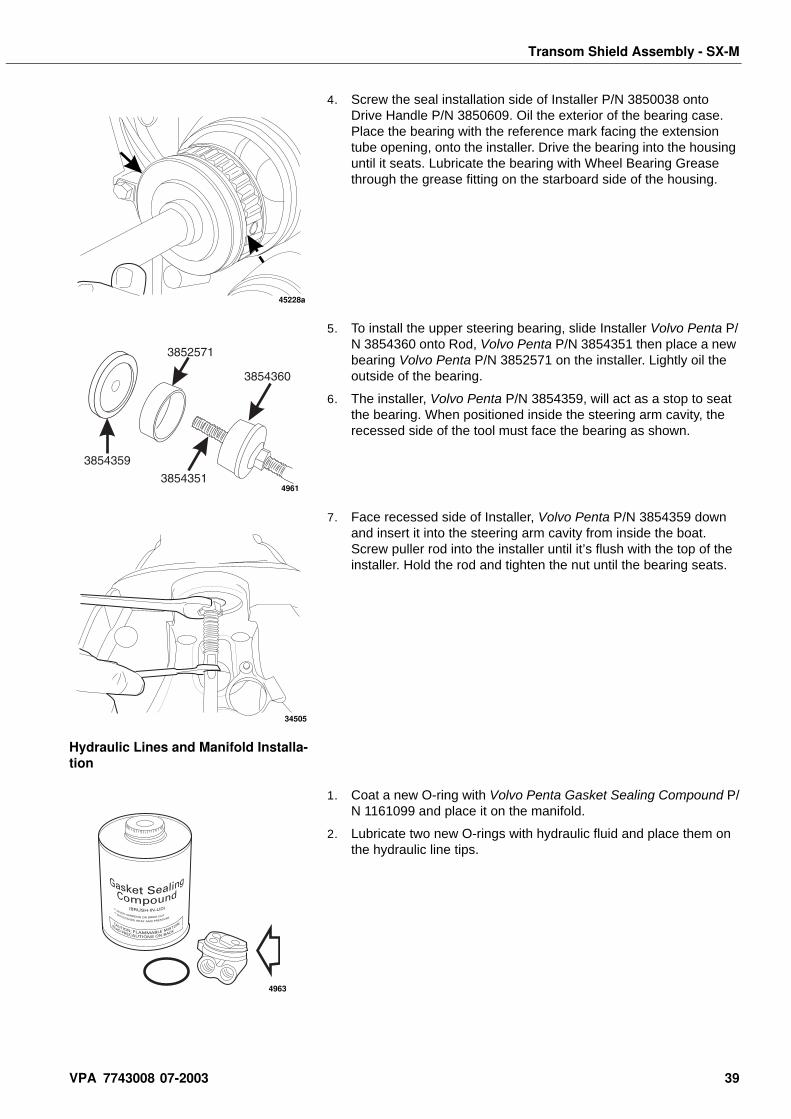
1. Face the open end of a new gimbal housing seal toward Installer, Volvo Penta P/N 3850038, and place it on the projecting nose of the tool. Lightly coat the metal case with Volvo Penta Gasket Seal-ing Compound.
2. Screw the installer onto Drive Handle, Volvo Penta P/N 3850609. Drive the seal into the housing until it seats. Coat the seal lip with Volvo Penta Grease P/N 828250.
3. To ensure adequate lubrication of the gimbal bearing, it must be correctly positioned prior to installation. Rotate the outer band until its slot aligns with the lubrication hole. Scribe a reference mark at this point on the bearing case.
48639
45277a
4959
38 VPA 7743008 07-2003
Transom Shield Assembly - SX-M
4. Screw the seal installation side of Installer P/N 3850038 onto Drive Handle P/N 3850609. Oil the exterior of the bearing case. Place the bearing with the reference mark facing the extension tube opening, onto the installer. Drive the bearing into the housing until it seats. Lubricate the bearing with Wheel Bearing Grease through the grease fitting on the starboard side of the housing.
5. To install the upper steering bearing, slide Installer Volvo Penta P/N 3854360 onto Rod, Volvo Penta P/N 3854351 then place a new bearing Volvo Penta P/N 3852571 on the installer. Lightly oil the outside of the bearing.
6. The installer, Volvo Penta P/N 3854359, will act as a stop to seat the bearing. When positioned inside the steering arm cavity, the recessed side of the tool must face the bearing as shown.
7. Face recessed side of Installer, Volvo Penta P/N 3854359 down and insert it into the steering arm cavity from inside the boat. Screw puller rod into the installer until it’s flush with the top of the installer. Hold the rod and tighten the nut until the bearing seats.
Hydraulic Lines and Manifold Installa-tion
1. Coat a new O-ring with Volvo Penta Gasket Sealing Compound P/N 1161099 and place it on the manifold.
2. Lubricate two new O-rings with hydraulic fluid and place them on the hydraulic line tips.
45228a
4961
34505
4963
VPA 7743008 07-2003 39
Transom Shield Assembly - SX-M
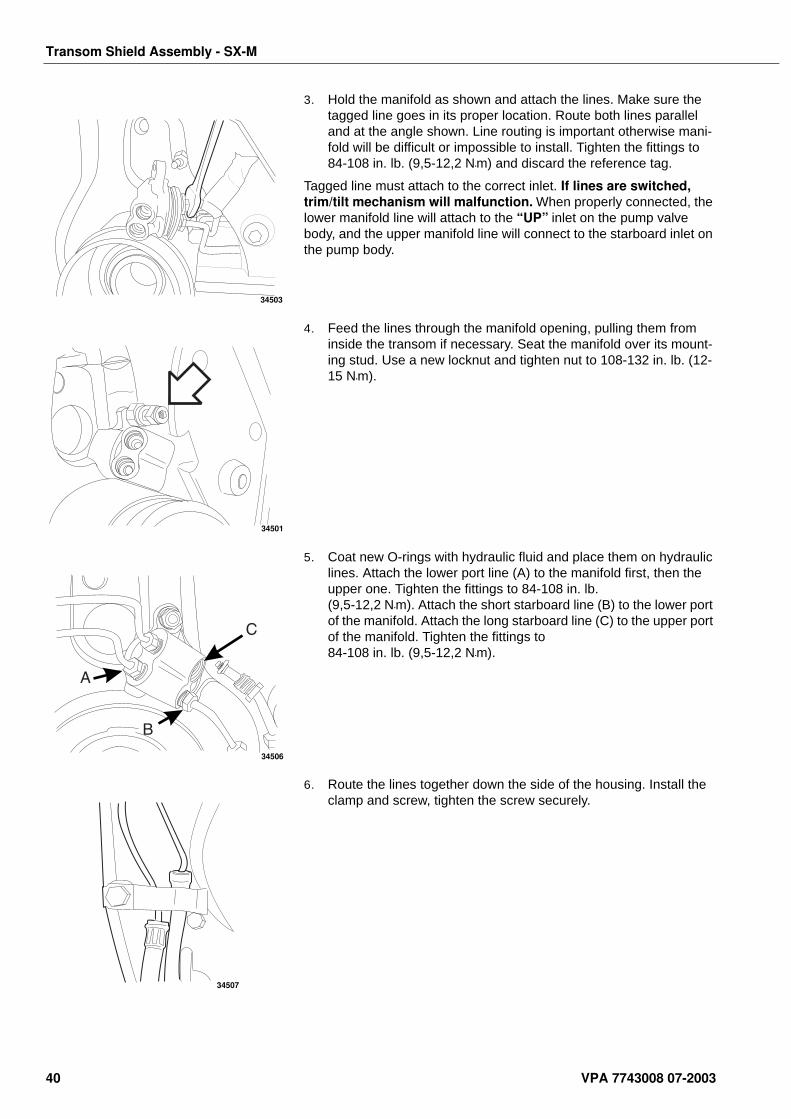
3. Hold the manifold as shown and attach the lines. Make sure the tagged line goes in its proper location. Route both lines parallel and at the angle shown. Line routing is important otherwise mani-fold will be difficult or impossible to install. Tighten the fittings to 84-108 in. lb. (9,5-12,2 N•m) and discard the reference tag.
Tagged line must attach to the correct inlet. If lines are switched, trim/tilt mechanism will malfunction. When properly connected, the lower manifold line will attach to the “UP” inlet on the pump valve body, and the upper manifold line will connect to the starboard inlet on the pump body.
4. Feed the lines through the manifold opening, pulling them from inside the transom if necessary. Seat the manifold over its mount-ing stud. Use a new locknut and tighten nut to 108-132 in. lb. (12-15 N•m).
5. Coat new O-rings with hydraulic fluid and place them on hydraulic lines. Attach the lower port line (A) to the manifold first, then the upper one. Tighten the fittings to 84-108 in. lb. (9,5-12,2 N•m). Attach the short starboard line (B) to the lower port of the manifold. Attach the long starboard line (C) to the upper port of the manifold. Tighten the fittings to 84-108 in. lb. (9,5-12,2 N•m).
6. Route the lines together down the side of the housing. Install the clamp and screw, tighten the screw securely.
34503
34501
34506
34507
40 VPA 7743008 07-2003
Transom Shield Assembly - SX-M
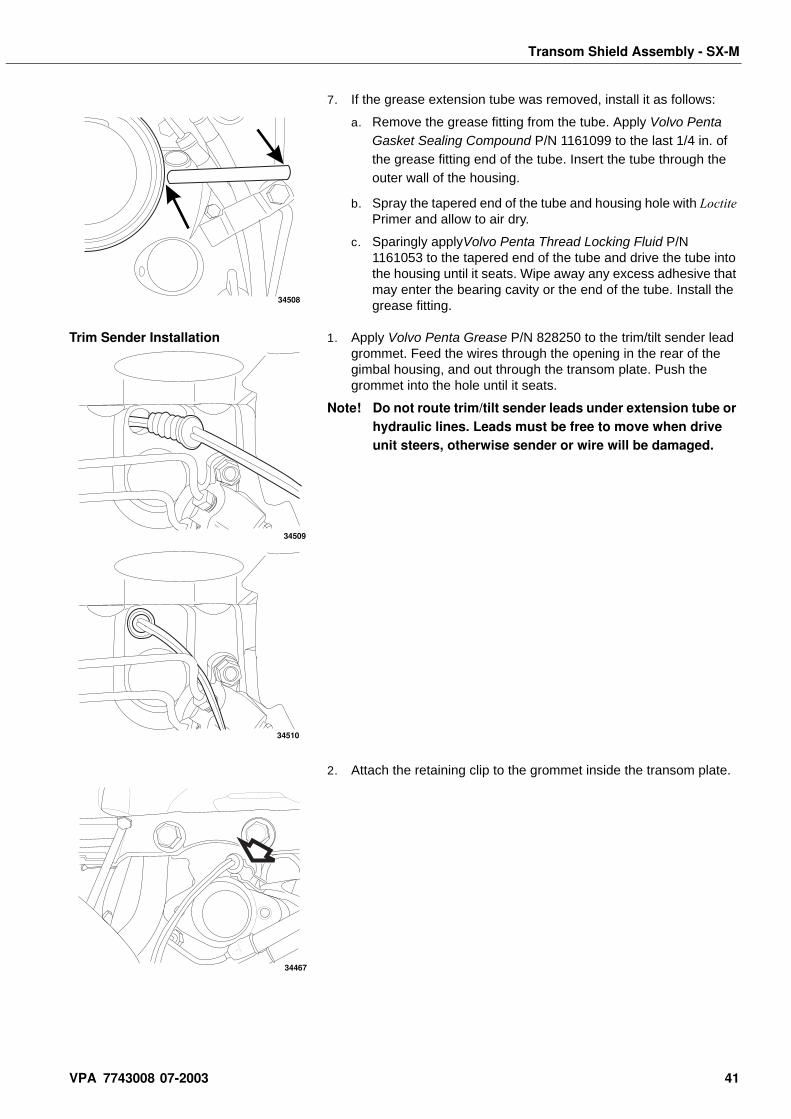
7. If the grease extension tube was removed, install it as follows:
a. Remove the grease fitting from the tube. Apply Volvo Penta Gasket Sealing Compound P/N 1161099 to the last 1/4 in. of the grease fitting end of the tube. Insert the tube through the outer wall of the housing.
b. Spray the tapered end of the tube and housing hole with Loctite Primer and allow to air dry.
c. Sparingly applyVolvo Penta Thread Locking Fluid P/N 1161053 to the tapered end of the tube and drive the tube into the housing until it seats. Wipe away any excess adhesive that may enter the bearing cavity or the end of the tube. Install the grease fitting.
Trim Sender Installation 1. Apply Volvo Penta Grease P/N 828250 to the trim/tilt sender lead grommet. Feed the wires through the opening in the rear of the gimbal housing, and out through the transom plate. Push the grommet into the hole until it seats.
Note! Do not route trim/tilt sender leads under extension tube or hydraulic lines. Leads must be free to move when drive unit steers, otherwise sender or wire will be damaged.
2. Attach the retaining clip to the grommet inside the transom plate.
34508
34509
34510
34467
VPA 7743008 07-2003 41
Transom Shield Assembly - SX-M
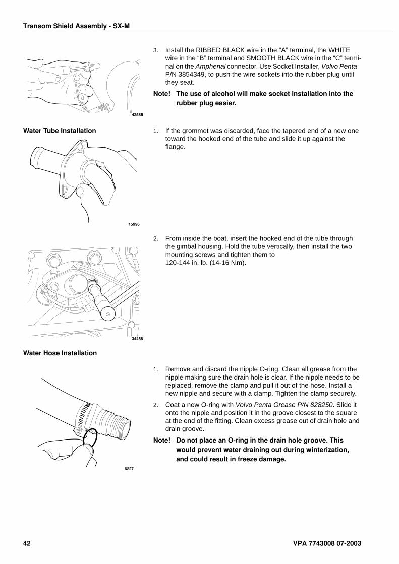
3. Install the RIBBED BLACK wire in the “A” terminal, the WHITE wire in the “B” terminal and SMOOTH BLACK wire in the “C” termi-nal on the Amphenal connector. Use Socket Installer, Volvo Penta P/N 3854349, to push the wire sockets into the rubber plug until they seat.
Note! The use of alcohol will make socket installation into the rubber plug easier.
Water Tube Installation 1. If the grommet was discarded, face the tapered end of a new one toward the hooked end of the tube and slide it up against the flange.
2. From inside the boat, insert the hooked end of the tube through the gimbal housing. Hold the tube vertically, then install the two mounting screws and tighten them to 120-144 in. lb. (14-16 N•m).
Water Hose Installation
1. Remove and discard the nipple O-ring. Clean all grease from the nipple making sure the drain hole is clear. If the nipple needs to be replaced, remove the clamp and pull it out of the hose. Install a new nipple and secure with a clamp. Tighten the clamp securely.
2. Coat a new O-ring with Volvo Penta Grease P/N 828250. Slide it onto the nipple and position it in the groove closest to the square at the end of the fitting. Clean excess grease out of drain hole and drain groove.
Note! Do not place an O-ring in the drain hole groove. This would prevent water draining out during winterization, and could result in freeze damage.
42586
15996
34468
6227
42 VPA 7743008 07-2003
Transom Shield Assembly - SX-M
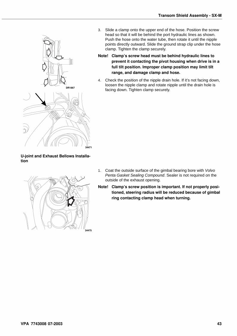
3. Slide a clamp onto the upper end of the hose. Position the screw head so that it will be behind the port hydraulic lines as shown. Push the hose onto the water tube, then rotate it until the nipple points directly outward. Slide the ground strap clip under the hose clamp. Tighten the clamp securely.
Note! Clamp’s screw head must be behind hydraulic lines to prevent it contacting the pivot housing when drive is in a full tilt position. Improper clamp position may limit tilt range, and damage clamp and hose.
4. Check the position of the nipple drain hole. If it’s not facing down, loosen the nipple clamp and rotate nipple until the drain hole is facing down. Tighten clamp securely.
U-joint and Exhaust Bellows Installa-tion
1. Coat the outside surface of the gimbal bearing bore with Volvo Penta Gasket Sealing Compound. Sealer is not required on the outside of the exhaust opening.
Note! Clamp’s screw position is important. If not properly posi-tioned, steering radius will be reduced because of gimbal ring contacting clamp head when turning.
DR1867
34471
34475
VPA 7743008 07-2003 43
Transom Shield Assembly - SX-M
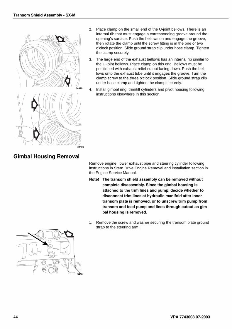
2. Place clamp on the small end of the U-joint bellows. There is an internal rib that must engage a corresponding groove around the opening’s surface. Push the bellows on and engage the groove, then rotate the clamp until the screw fitting is in the one or two o’clock position. Slide ground strap clip under hose clamp. Tighten the clamp securely.
3. The large end of the exhaust bellows has an internal rib similar to the U-joint bellows. Place clamp on this end. Bellows must be positioned with exhaust relief cutout facing down. Push the bel-lows onto the exhaust tube until it engages the groove. Turn the clamp screw to the three o’clock position. Slide ground strap clip under hose clamp and tighten the clamp securely.
4. Install gimbal ring, trim/tilt cylinders and pivot housing following instructions elsewhere in this section.
Gimbal Housing RemovalRemove engine, lower exhaust pipe and steering cylinder following instructions in Stern Drive Engine Removal and installation section in the Engine Service Manual.
Note! The transom shield assembly can be removed without complete disassembly. Since the gimbal housing is attached to the trim lines and pump, decide whether to disconnect trim lines at hydraulic manifold after inner transom plate is removed, or to unscrew trim pump from transom and feed pump and lines through cutout as gim-bal housing is removed.
1. Remove the screw and washer securing the transom plate ground strap to the steering arm.
34479
34480
3400
44 VPA 7743008 07-2003
Transom Shield Assembly - SX-M
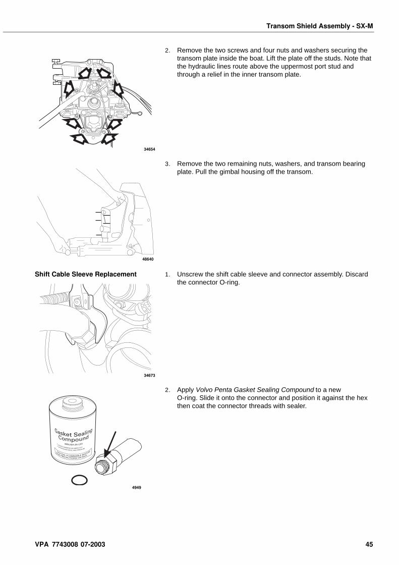
2. Remove the two screws and four nuts and washers securing the transom plate inside the boat. Lift the plate off the studs. Note that the hydraulic lines route above the uppermost port stud and through a relief in the inner transom plate.
3. Remove the two remaining nuts, washers, and transom bearing plate. Pull the gimbal housing off the transom.
Shift Cable Sleeve Replacement 1. Unscrew the shift cable sleeve and connector assembly. Discard the connector O-ring.
2. Apply Volvo Penta Gasket Sealing Compound to a new O-ring. Slide it onto the connector and position it against the hex then coat the connector threads with sealer.
34654
48640
34673
4949
VPA 7743008 07-2003 45
Transom Shield Assembly - SX-M
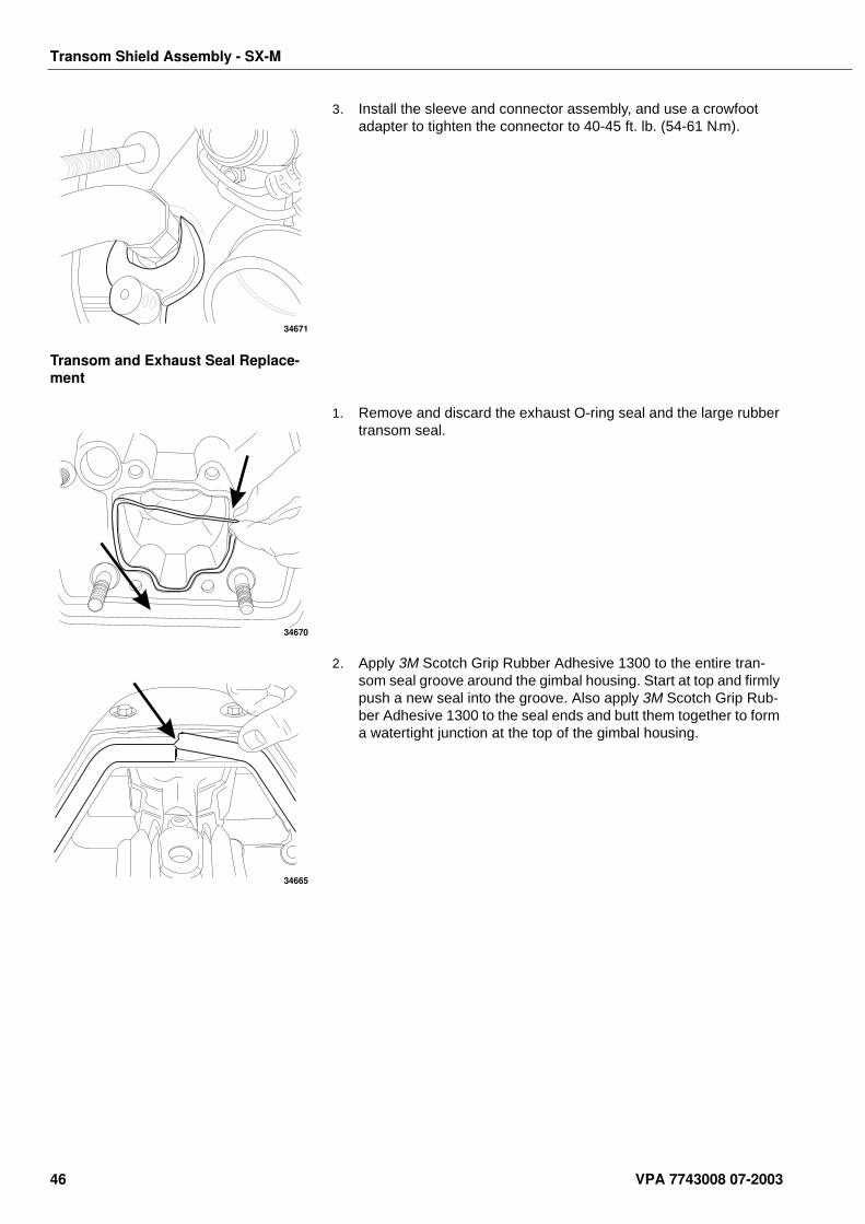
3. Install the sleeve and connector assembly, and use a crowfoot adapter to tighten the connector to 40-45 ft. lb. (54-61 N•m).
Transom and Exhaust Seal Replace-ment
1. Remove and discard the exhaust O-ring seal and the large rubber transom seal.
2. Apply 3M Scotch Grip Rubber Adhesive 1300 to the entire tran-som seal groove around the gimbal housing. Start at top and firmly push a new seal into the groove. Also apply 3M Scotch Grip Rub-ber Adhesive 1300 to the seal ends and butt them together to form a watertight junction at the top of the gimbal housing.
34671
34670
34665
46 VPA 7743008 07-2003
Transom Shield Assembly - SX-M
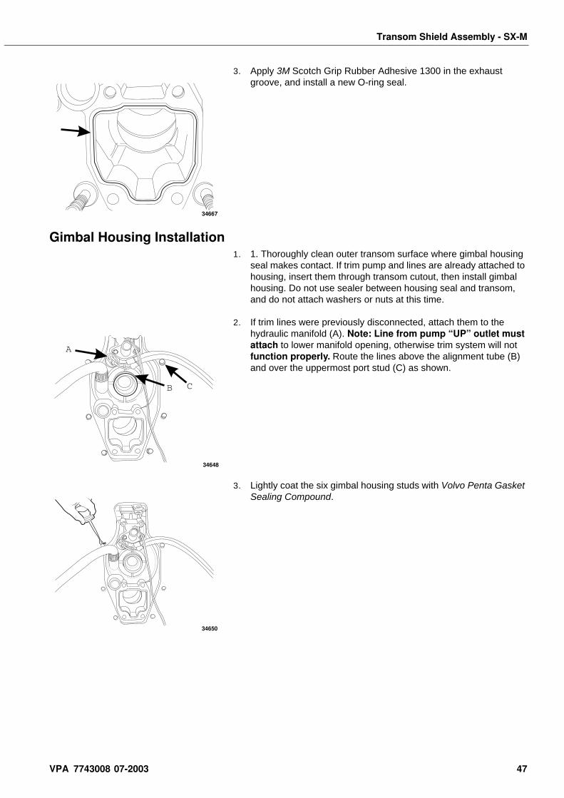
3. Apply 3M Scotch Grip Rubber Adhesive 1300 in the exhaust groove, and install a new O-ring seal.
Gimbal Housing Installation1. 1. Thoroughly clean outer transom surface where gimbal housing
seal makes contact. If trim pump and lines are already attached to housing, insert them through transom cutout, then install gimbal housing. Do not use sealer between housing seal and transom, and do not attach washers or nuts at this time.
2. If trim lines were previously disconnected, attach them to the hydraulic manifold (A). Note: Line from pump “UP” outlet must attach to lower manifold opening, otherwise trim system will not function properly. Route the lines above the alignment tube (B) and over the uppermost port stud (C) as shown.
3. Lightly coat the six gimbal housing studs with Volvo Penta Gasket Sealing Compound.
34667
A
B C
34648
34650
VPA 7743008 07-2003 47
Transom Shield Assembly - SX-M
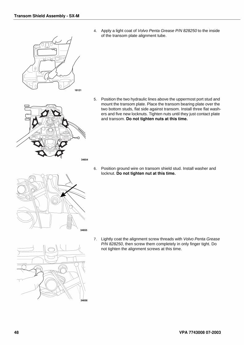
4. Apply a light coat of Volvo Penta Grease P/N 828250 to the inside of the transom plate alignment tube.
5. Position the two hydraulic lines above the uppermost port stud and mount the transom plate. Place the transom bearing plate over the two bottom studs, flat side against transom. Install three flat wash-ers and five new locknuts. Tighten nuts until they just contact plate and transom. Do not tighten nuts at this time.
6. Position ground wire on transom shield stud. Install washer and locknut. Do not tighten nut at this time.
7. Lightly coat the alignment screw threads with Volvo Penta Grease P/N 828250, then screw them completely in only finger tight. Do not tighten the alignment screws at this time.
18121
34654
34655
34656
48 VPA 7743008 07-2003
Transom Shield Assembly - SX-M
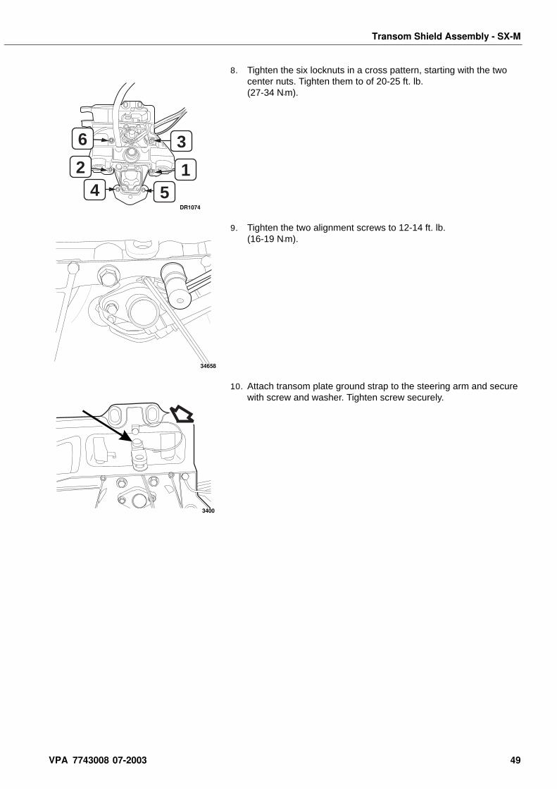
8. Tighten the six locknuts in a cross pattern, starting with the two center nuts. Tighten them to of 20-25 ft. lb. (27-34 N•m).
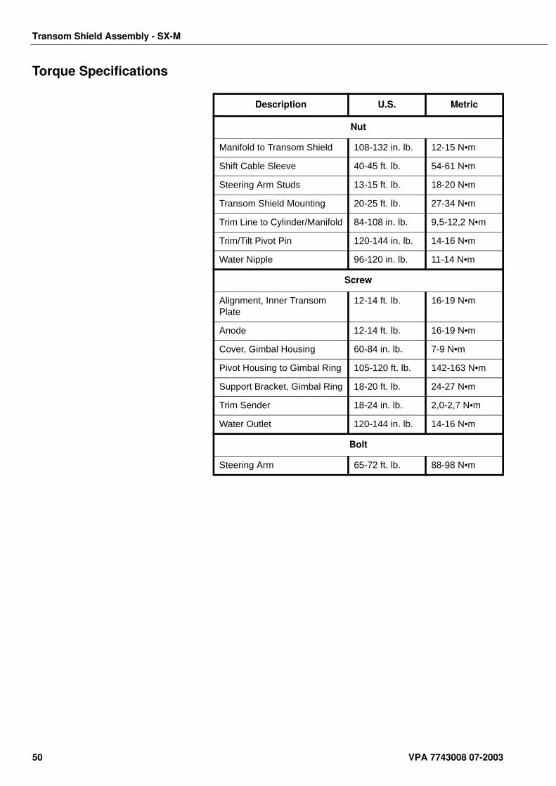
9. Tighten the two alignment screws to 12-14 ft. lb. (16-19 N•m).
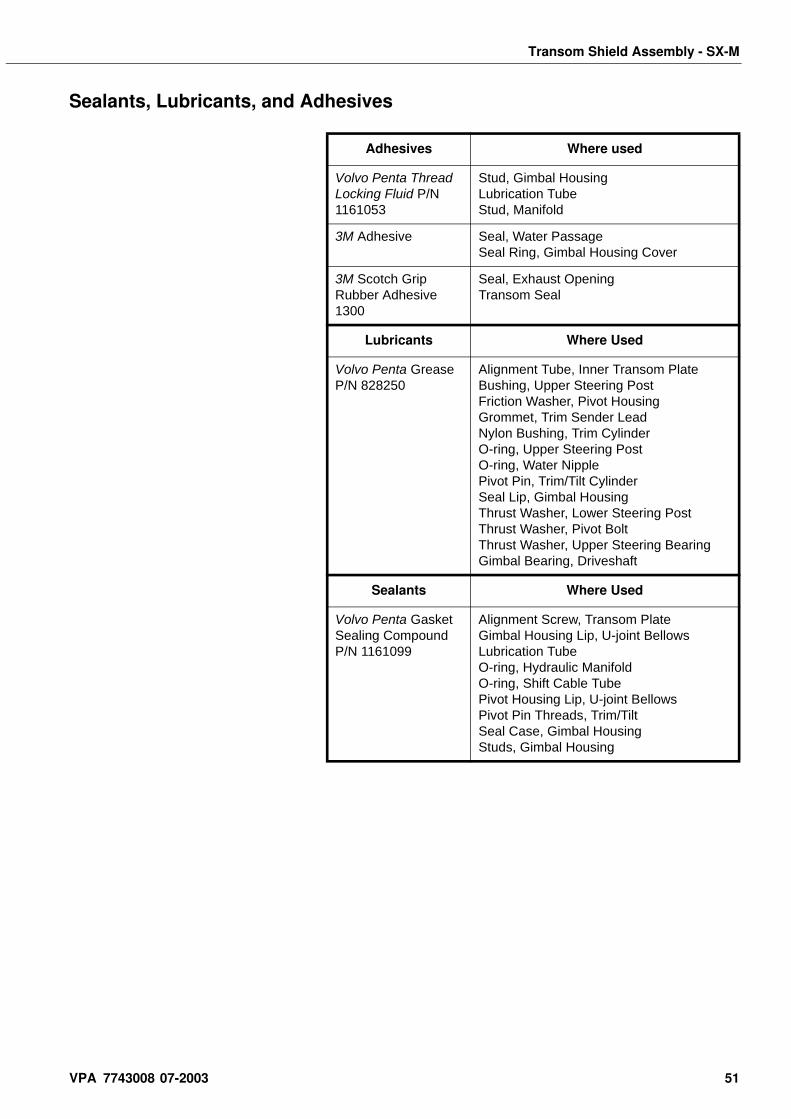
10. Attach transom plate ground strap to the steering arm and secure with screw and washer. Tighten screw securely.
3
1
6
24 5
DR1074
34658
3400
VPA 7743008 07-2003 49
Transom Shield Assembly - SX-M
Torque Specifications
Description U.S. Metric
Nut
Manifold to Transom Shield 108-132 in. lb. 12-15 N•m
Shift Cable Sleeve 40-45 ft. lb. 54-61 N•m
Steering Arm Studs 13-15 ft. lb. 18-20 N•m
Transom Shield Mounting 20-25 ft. lb. 27-34 N•m
Trim Line to Cylinder/Manifold 84-108 in. lb. 9,5-12,2 N•m
Trim/Tilt Pivot Pin 120-144 in. lb. 14-16 N•m
Water Nipple 96-120 in. lb. 11-14 N•m
Screw
Alignment, Inner Transom Plate
12-14 ft. lb. 16-19 N•m
Anode 12-14 ft. lb. 16-19 N•m
Cover, Gimbal Housing 60-84 in. lb. 7-9 N•m
Pivot Housing to Gimbal Ring 105-120 ft. lb. 142-163 N•m
Support Bracket, Gimbal Ring 18-20 ft. lb. 24-27 N•m
Trim Sender 18-24 in. lb. 2,0-2,7 N•m
Water Outlet 120-144 in. lb. 14-16 N•m
Bolt
Steering Arm 65-72 ft. lb. 88-98 N•m
50 VPA 7743008 07-2003
Transom Shield Assembly - SX-M
Sealants, Lubricants, and Adhesives
Adhesives Where used
Volvo Penta Thread Locking Fluid P/N 1161053
Stud, Gimbal HousingLubrication TubeStud, Manifold
3M Adhesive Seal, Water PassageSeal Ring, Gimbal Housing Cover
3M Scotch Grip Rubber Adhesive 1300
Seal, Exhaust OpeningTransom Seal
Lubricants Where Used
Volvo Penta Grease P/N 828250
Alignment Tube, Inner Transom PlateBushing, Upper Steering PostFriction Washer, Pivot HousingGrommet, Trim Sender LeadNylon Bushing, Trim CylinderO-ring, Upper Steering PostO-ring, Water NipplePivot Pin, Trim/Tilt CylinderSeal Lip, Gimbal HousingThrust Washer, Lower Steering PostThrust Washer, Pivot BoltThrust Washer, Upper Steering BearingGimbal Bearing, Driveshaft
Sealants Where Used
Volvo Penta Gasket Sealing Compound P/N 1161099
Alignment Screw, Transom PlateGimbal Housing Lip, U-joint BellowsLubrication TubeO-ring, Hydraulic ManifoldO-ring, Shift Cable TubePivot Housing Lip, U-joint BellowsPivot Pin Threads, Trim/TiltSeal Case, Gimbal HousingStuds, Gimbal Housing
VPA 7743008 07-2003 51
Transom Shield Assembly - SX-M
Service Chart
E
D
BB
B
B
B
B
B
B
B
B
C
CC
FE A
E
C
C
60-84 in. Lb.(7-9 N•m)
65-72 ft. Lb.(88-98 N•m)
13-15 ft. Lb.(18-20 N•m)
120-144 in. Lb.(14-16 N•m)
20-25 ft. Lb.(27-34 N•m)
40-45 ft. Lb.(54-61 N•m)
108-132 in. Lb.(12-15 N•m)
84-108 in. Lb(9,5-12,2 N•m)
105-120 ft. Lb.(142-163 N•m)
96-120 in. Lb.(1-14 N•m)
18-20 ft. Lb.(24-27 N•m)
18-24 in. Lb.(2,0-2,7 N•m)
12-14 ft. Lb.(16-19 N•m)
D
DRC7454
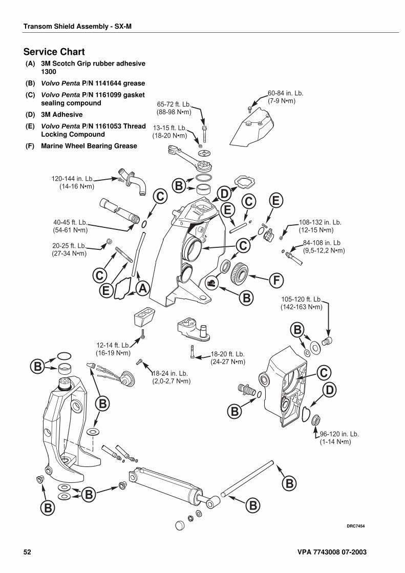
(A) 3M Scotch Grip rubber adhesive 1300
(B) Volvo Penta P/N 1141644 grease
(C) Volvo Penta P/N 1161099 gasket sealing compound
(D) 3M Adhesive
(E) Volvo Penta P/N 1161053 Thread Locking Compound
(F) Marine Wheel Bearing Grease
52 VPA 7743008 07-2003
Transom Shield Assembly SX-MHP
Transom Shield Assembly SX-MHPTable of Contents Special Tools . . . . . . . . . . . . . . . . . . . . . . . . . . . . . . . . . . . . . . 56
Sealants, Lubricants and Adhesives . . . . . . . . . . . . . . . . . . . 56Trim/Tilt Cylinder Installation . . . . . . . . . . . . . . . . . . . . . . . . . 58Pivot Housing Removal. . . . . . . . . . . . . . . . . . . . . . . . . . . . . . 59Pivot Housing Assembly. . . . . . . . . . . . . . . . . . . . . . . . . . . . . 62Pivot Housing Installation. . . . . . . . . . . . . . . . . . . . . . . . . . . . 62Gimbal Ring Removal . . . . . . . . . . . . . . . . . . . . . . . . . . . . . . . 64Gimbal Ring Disassembly. . . . . . . . . . . . . . . . . . . . . . . . . . . . 67Gimbal Ring Assembly . . . . . . . . . . . . . . . . . . . . . . . . . . . . . . 67Gimbal Ring Installation . . . . . . . . . . . . . . . . . . . . . . . . . . . . . 68Trim Sender Adjustment . . . . . . . . . . . . . . . . . . . . . . . . . . . . . 71Gimbal Housing Disassembly . . . . . . . . . . . . . . . . . . . . . . . . 72Anode Replacement . . . . . . . . . . . . . . . . . . . . . . . . . . . . . . . . 72Trim Sender Removal . . . . . . . . . . . . . . . . . . . . . . . . . . . . . . . 73Water Tube Removal . . . . . . . . . . . . . . . . . . . . . . . . . . . . . . . . 73Hydraulic Lines and Manifold Removal. . . . . . . . . . . . . . . . . 74Steering Bearing, Gimbal Bearing and Seal Removal . . . . . 75Gimbal Housing Cleaning and Inspection. . . . . . . . . . . . . . . 75
Gimbal Housing Assembly . . . . . . . . . . . . . . . . . . . . 76Steering Bearing, Gimbal Bearing and Seal Installation . . . 76Hydraulic Lines and Manifold Installation. . . . . . . . . . . . . . . 77Trim Sender Installation . . . . . . . . . . . . . . . . . . . . . . . . . . . . . 79Anode and Sensor Housing Installation . . . . . . . . . . . . . . . . 80Water Tube Installation . . . . . . . . . . . . . . . . . . . . . . . . . . . . . . 80Water Hose Installation . . . . . . . . . . . . . . . . . . . . . . . . . . . . . . 80U-joint and Exhaust Bellows Installation . . . . . . . . . . . . . . . 81Gimbal Housing and Transom Plate Removal . . . . . . . . . . . 82Shift Cable Sleeve Replacement . . . . . . . . . . . . . . . . . . . . . . 83Transom and Exhaust Seal Replacement . . . . . . . . . . . . . . . 84Gimbal Housing and Transom Plate Installation . . . . . . . . . 85
Torque Specifications . . . . . . . . . . . . . . . . . . . . . . . . 87Sealants Lubricants, Adhesives . . . . . . . . . . . . . . . . 88Service Chart . . . . . . . . . . . . . . . . . . . . . . . . . . . . . . . 89
Safety Warnings Before working on any part of the transom bracket assembly, read the section called Safety at the end of this manual.
When replacement parts are required, use genuine Volvo Penta or parts with equivalent characteristics including type, strength and material. Failure to do so may result in product malfunction and possible injury to the operator and/or passengers.
Some screw holes have special Heli-Coil inserts that provide a thread-locking feature. Do not clean Heli-Coil holes with a thread tap. This will damage the Heli-Coil inserts and force their replacement.
VPA 7743008 07-2003 53
Transom Shield Assembly SX-MHP
Special Tools
Owatonna Service Tools OEM 4184Slide Hammer
Order From: OTC Division of SPX Corporation
655 Eisenhower Drive
Owatonna, Minnesota 55060 USA
Toll free order line:1-800-533-5338 or 1-800-533-0492
http://www.otctools.com
Sealants, Lubricants and Adhesives Cleaning Solvent
Volvo Penta Gasket Sealing Compound P/N 1161099
Loctite Primer N
Volvo Penta Thread Locking Compound P/N 1161053
Volvo Penta Grease P/N 828250
3M Adhesive
Wheel Bearing Grease
Remove the sterndrive following the procedure in Sterndrive Removal and Installation section in this manual. If the complete transom bracket assembly is being rebuilt or replaced, remove engine following procedure in the Installation Manual.
Tool Name Volvo P/N Panel Location
Drive Handle 3850609 A
Driver 3854356 E
Insert Tool 3854349 B
Installer 3854359 E
Installer 3854360 E
Installer - K*
Remover/Installer 3854355 E
Remover/Installer 3845358 E
Retaining Ring Pliers 3850608 B
Rod 3854351 C
Socket Removal Tool 3854350 B
* Same panel position as obsoleted Installer, P/N 912279.
54 VPA 7743008 07-2003
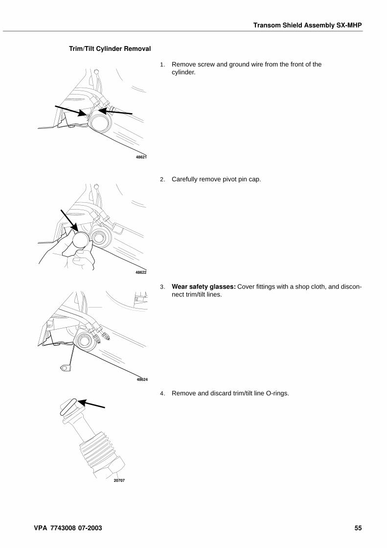
Transom Shield Assembly SX-MHP
Trim/Tilt Cylinder Removal
1. Remove screw and ground wire from the front of the cylinder.
2. Carefully remove pivot pin cap.
3. Wear safety glasses: Cover fittings with a shop cloth, and discon-nect trim/tilt lines.
4. Remove and discard trim/tilt line O-rings.
48621
48622
48624
20707
VPA 7743008 07-2003 55
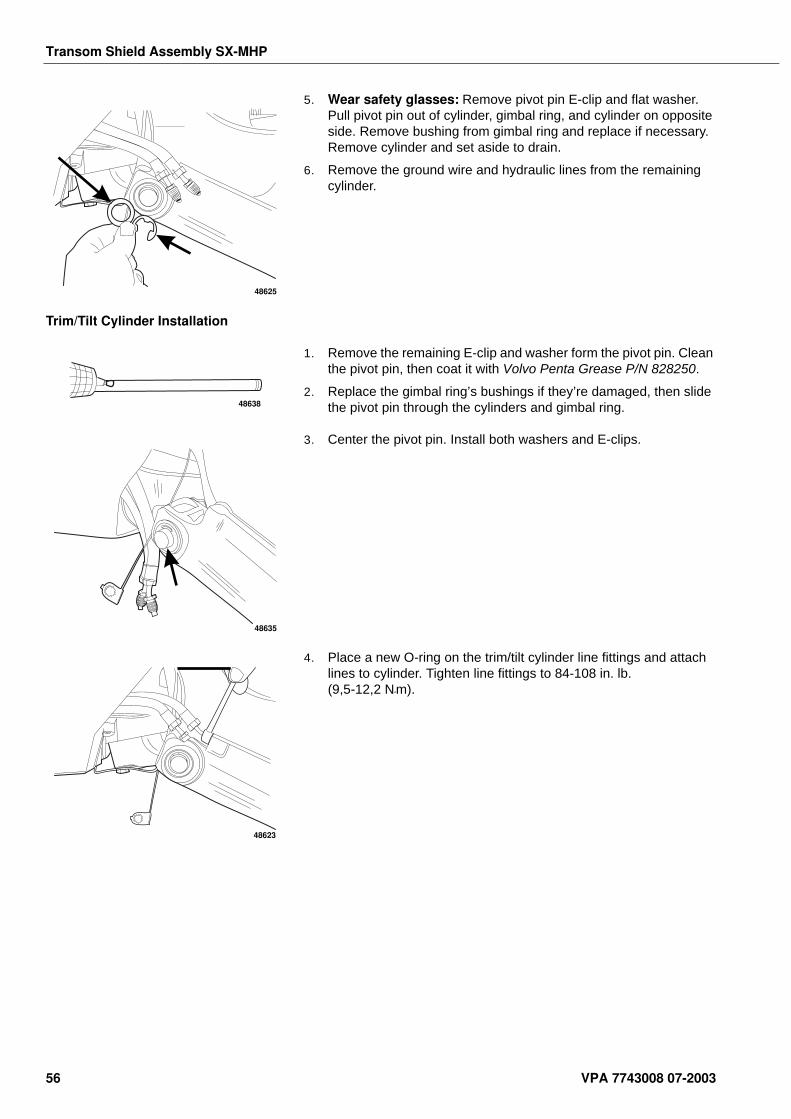
Transom Shield Assembly SX-MHP
5. Wear safety glasses: Remove pivot pin E-clip and flat washer. Pull pivot pin out of cylinder, gimbal ring, and cylinder on opposite side. Remove bushing from gimbal ring and replace if necessary. Remove cylinder and set aside to drain.
6. Remove the ground wire and hydraulic lines from the remaining cylinder.
Trim/Tilt Cylinder Installation
1. Remove the remaining E-clip and washer form the pivot pin. Clean the pivot pin, then coat it with Volvo Penta Grease P/N 828250.
2. Replace the gimbal ring’s bushings if they’re damaged, then slide the pivot pin through the cylinders and gimbal ring.
3. Center the pivot pin. Install both washers and E-clips.
4. Place a new O-ring on the trim/tilt cylinder line fittings and attach lines to cylinder. Tighten line fittings to 84-108 in. lb. (9,5-12,2 N•m).
48625
48638
48635
48623
56 VPA 7743008 07-2003
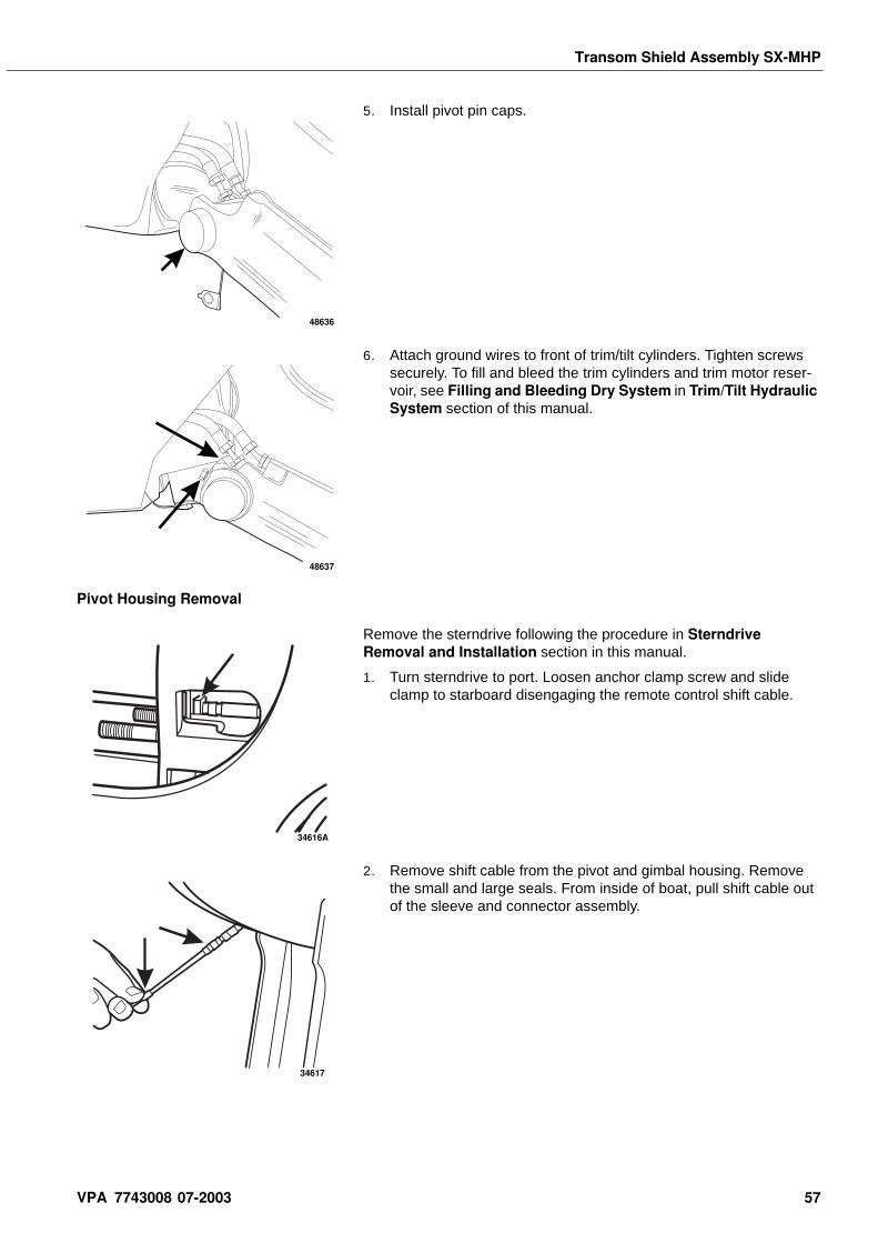
Transom Shield Assembly SX-MHP
5. Install pivot pin caps.
6. Attach ground wires to front of trim/tilt cylinders. Tighten screws securely. To fill and bleed the trim cylinders and trim motor reser-voir, see Filling and Bleeding Dry System in Trim/Tilt Hydraulic System section of this manual.
Pivot Housing Removal
Remove the sterndrive following the procedure in Sterndrive Removal and Installation section in this manual.
1. Turn sterndrive to port. Loosen anchor clamp screw and slide clamp to starboard disengaging the remote control shift cable.
2. Remove shift cable from the pivot and gimbal housing. Remove the small and large seals. From inside of boat, pull shift cable out of the sleeve and connector assembly.
48636
48637
34616A
34617
VPA 7743008 07-2003 57
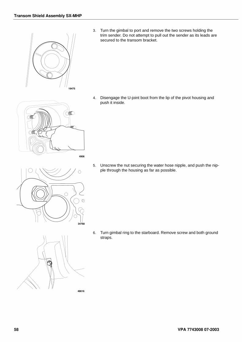
Transom Shield Assembly SX-MHP
3. Turn the gimbal to port and remove the two screws holding the trim sender. Do not attempt to pull out the sender as its leads are secured to the transom bracket.
4. Disengage the U-joint boot from the lip of the pivot housing and push it inside.
5. Unscrew the nut securing the water hose nipple, and push the nip-ple through the housing as far as possible.
6. Turn gimbal ring to the starboard. Remove screw and both ground straps.
19475
4906
34768
48616
58 VPA 7743008 07-2003
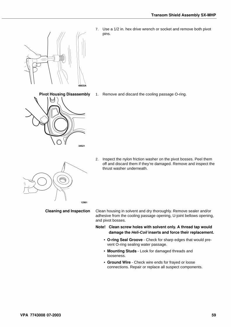
Transom Shield Assembly SX-MHP
7. Use a 1/2 in. hex drive wrench or socket and remove both pivot pins.
Pivot Housing Disassembly 1. Remove and discard the cooling passage O-ring.
2. Inspect the nylon friction washer on the pivot bosses. Peel them off and discard them if they’re damaged. Remove and inspect the thrust washer underneath.
Cleaning and Inspection Clean housing in solvent and dry thoroughly. Remove sealer and/or adhesive from the cooling passage opening, U-joint bellows opening, and pivot bosses.
Note! Clean screw holes with solvent only. A thread tap would damage the Heli-Coil inserts and force their replacement.
• O-ring Seal Groove - Check for sharp edges that would pre-vent O-ring sealing water passage.
• Mounting Studs - Look for damaged threads and looseness.
• Ground Wire - Check wire ends for frayed or loose connections. Repair or replace all suspect components.
48633A
34521
12961
VPA 7743008 07-2003 59
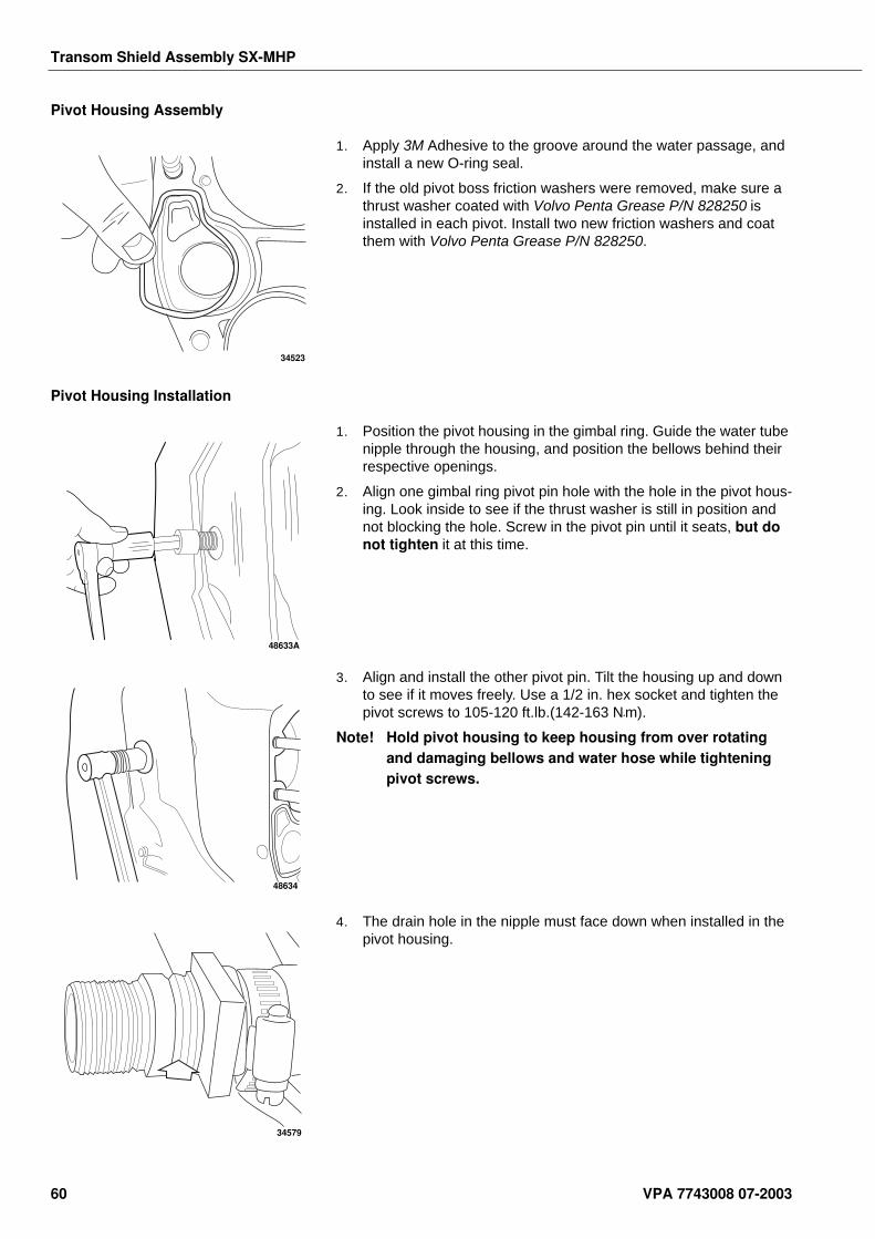
Transom Shield Assembly SX-MHP
Pivot Housing Assembly
1. Apply 3M Adhesive to the groove around the water passage, and install a new O-ring seal.
2. If the old pivot boss friction washers were removed, make sure a thrust washer coated with Volvo Penta Grease P/N 828250 is installed in each pivot. Install two new friction washers and coat them with Volvo Penta Grease P/N 828250.
Pivot Housing Installation
1. Position the pivot housing in the gimbal ring. Guide the water tube nipple through the housing, and position the bellows behind their respective openings.
2. Align one gimbal ring pivot pin hole with the hole in the pivot hous-ing. Look inside to see if the thrust washer is still in position and not blocking the hole. Screw in the pivot pin until it seats, but do not tighten it at this time.
3. Align and install the other pivot pin. Tilt the housing up and down to see if it moves freely. Use a 1/2 in. hex socket and tighten the pivot screws to 105-120 ft.lb.(142-163 N•m).
Note! Hold pivot housing to keep housing from over rotating and damaging bellows and water hose while tightening pivot screws.
4. The drain hole in the nipple must face down when installed in the pivot housing.
34523
48633A
48634
34579
60 VPA 7743008 07-2003
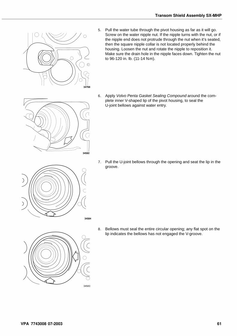
Transom Shield Assembly SX-MHP
5. Pull the water tube through the pivot housing as far as it will go. Screw on the water nipple nut. If the nipple turns with the nut, or if the nipple end does not protrude through the nut when it’s seated, then the square nipple collar is not located properly behind the housing. Loosen the nut and rotate the nipple to reposition it. Make sure the drain hole in the nipple faces down. Tighten the nut to 96-120 in. lb. (11-14 N•m).
6. Apply Volvo Penta Gasket Sealing Compound around the com-plete inner V-shaped lip of the pivot housing, to seal the U-joint bellows against water entry.
7. Pull the U-joint bellows through the opening and seat the lip in the groove.
8. Bellows must seal the entire circular opening; any flat spot on the lip indicates the bellows has not engaged the V-groove.
34768
34582
34584
34583
VPA 7743008 07-2003 61
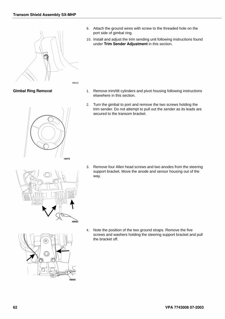
Transom Shield Assembly SX-MHP
9. Attach the ground wires with screw to the threaded hole on the port side of gimbal ring.
10. Install and adjust the trim sending unit following instructions found under Trim Sender Adjustment in this section.
Gimbal Ring Removal 1. Remove trim/tilt cylinders and pivot housing following instructions elsewhere in this section.
2. Turn the gimbal to port and remove the two screws holding the trim sender. Do not attempt to pull out the sender as its leads are secured to the transom bracket.
3. Remove four Allen head screws and two anodes from the steering support bracket. Move the anode and sensor housing out of the way.
4. Note the position of the two ground straps. Remove the five screws and washers holding the steering support bracket and pull the bracket off.
48616
19475
48665
48666
62 VPA 7743008 07-2003
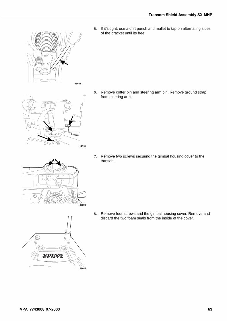
Transom Shield Assembly SX-MHP
5. If it’s tight, use a drift punch and mallet to tap on alternating sides of the bracket until its free.
6. Remove cotter pin and steering arm pin. Remove ground strap from steering arm.
7. Remove two screws securing the gimbal housing cover to the transom.
8. Remove four screws and the gimbal housing cover. Remove and discard the two foam seals from the inside of the cover.
48667
19351
J
48699
48617
VPA 7743008 07-2003 63
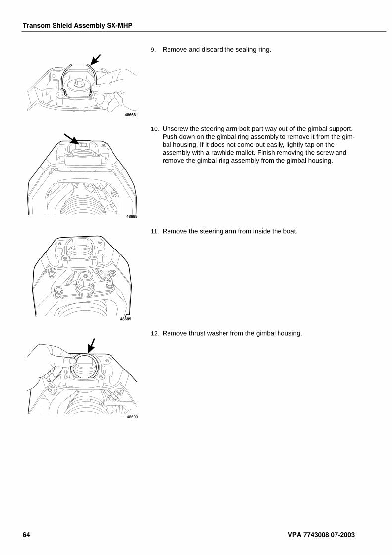
Transom Shield Assembly SX-MHP
9. Remove and discard the sealing ring.
10. Unscrew the steering arm bolt part way out of the gimbal support. Push down on the gimbal ring assembly to remove it from the gim-bal housing. If it does not come out easily, lightly tap on the assembly with a rawhide mallet. Finish removing the screw and remove the gimbal ring assembly from the gimbal housing.
11. Remove the steering arm from inside the boat.
12. Remove thrust washer from the gimbal housing.
48668
48688
48689
48690
64 VPA 7743008 07-2003
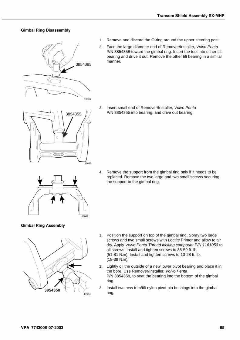
Transom Shield Assembly SX-MHP
Gimbal Ring Disassembly
1. Remove and discard the O-ring around the upper steering post.
2. Face the large diameter end of Remover/Installer, Volvo Penta P/N 3854358 toward the gimbal ring. Insert the tool into either tilt bearing and drive it out. Remove the other tilt bearing in a similar manner.
3. Insert small end of Remover/Installer, Volvo Penta P/N 3854355 into bearing, and drive out bearing.
4. Remove the support from the gimbal ring only if it needs to be replaced. Remove the two large and two small screws securing the support to the gimbal ring.
Gimbal Ring Assembly
1. Position the support on top of the gimbal ring. Spray two large screws and two small screws with Loctite Primer and allow to air dry. Apply Volvo Penta Thread locking compount P/N 1161053 to all screws. Install and tighten screws to 38-59 ft. lb. (51-81 N•m). Install and tighten screws to 13-28 ft. lb.(18-38 N•m).
2. Lightly oil the outside of a new lower pivot bearing and place it in the bore. Use Remover/Installer, Volvo Penta P/N 3854358, to seat the bearing into the bottom of the gimbal ring.
3. Install two new trim/tilt nylon pivot pin bushings into the gimbal ring.
19646
17685
48682
385435817684
VPA 7743008 07-2003 65
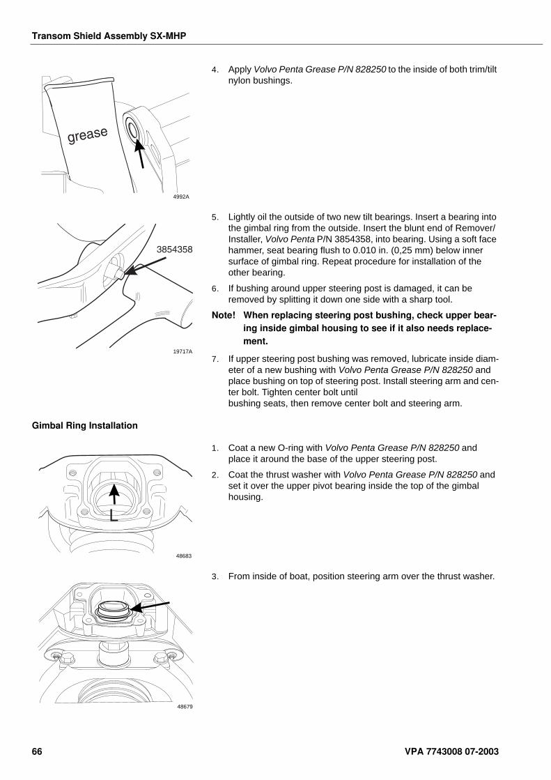
Transom Shield Assembly SX-MHP
4. Apply Volvo Penta Grease P/N 828250 to the inside of both trim/tilt nylon bushings.
5. Lightly oil the outside of two new tilt bearings. Insert a bearing into the gimbal ring from the outside. Insert the blunt end of Remover/ Installer, Volvo Penta P/N 3854358, into bearing. Using a soft face hammer, seat bearing flush to 0.010 in. (0,25 mm) below inner surface of gimbal ring. Repeat procedure for installation of the other bearing.
6. If bushing around upper steering post is damaged, it can be removed by splitting it down one side with a sharp tool.
Note! When replacing steering post bushing, check upper bear-ing inside gimbal housing to see if it also needs replace-ment.
7. If upper steering post bushing was removed, lubricate inside diam-eter of a new bushing with Volvo Penta Grease P/N 828250 and place bushing on top of steering post. Install steering arm and cen-ter bolt. Tighten center bolt until bushing seats, then remove center bolt and steering arm.
Gimbal Ring Installation
1. Coat a new O-ring with Volvo Penta Grease P/N 828250 and place it around the base of the upper steering post.
2. Coat the thrust washer with Volvo Penta Grease P/N 828250 and set it over the upper pivot bearing inside the top of the gimbal housing.
3. From inside of boat, position steering arm over the thrust washer.
4992A
19717A
L
48683
48679
66 VPA 7743008 07-2003
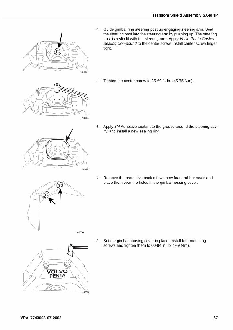
Transom Shield Assembly SX-MHP
4. Guide gimbal ring steering post up engaging steering arm. Seat the steering post into the steering arm by pushing up. The steering post is a slip fit with the steering arm. Apply Volvo Penta Gasket Sealing Compound to the center screw. Install center screw finger tight.
5. Tighten the center screw to 35-60 ft. lb. (45-75 N•m).
6. Apply 3M Adhesive sealant to the groove around the steering cav-ity, and install a new sealing ring.
7. Remove the protective back off two new foam rubber seals and place them over the holes in the gimbal housing cover.
8. Set the gimbal housing cover in place. Install four mounting screws and tighten them to 60-84 in. lb. (7-9 N•m).
48680
48681
48673
48674
VOLVOPENTA
48675
VPA 7743008 07-2003 67
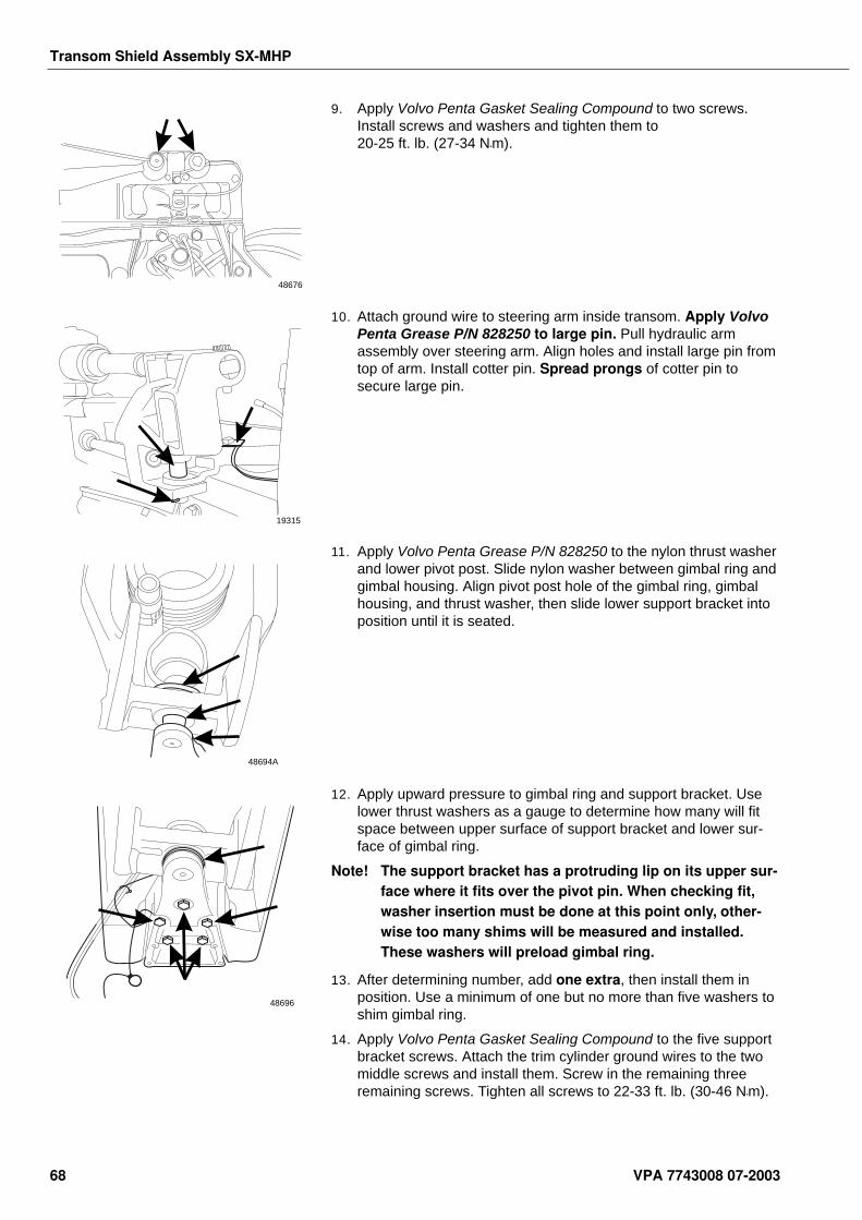
Transom Shield Assembly SX-MHP
9. Apply Volvo Penta Gasket Sealing Compound to two screws. Install screws and washers and tighten them to 20-25 ft. lb. (27-34 N•m).
10. Attach ground wire to steering arm inside transom. Apply Volvo Penta Grease P/N 828250 to large pin. Pull hydraulic arm assembly over steering arm. Align holes and install large pin from top of arm. Install cotter pin. Spread prongs of cotter pin to secure large pin.
11. Apply Volvo Penta Grease P/N 828250 to the nylon thrust washer and lower pivot post. Slide nylon washer between gimbal ring and gimbal housing. Align pivot post hole of the gimbal ring, gimbal housing, and thrust washer, then slide lower support bracket into position until it is seated.
12. Apply upward pressure to gimbal ring and support bracket. Use lower thrust washers as a gauge to determine how many will fit space between upper surface of support bracket and lower sur-face of gimbal ring.
Note! The support bracket has a protruding lip on its upper sur-face where it fits over the pivot pin. When checking fit, washer insertion must be done at this point only, other-wise too many shims will be measured and installed. These washers will preload gimbal ring.
13. After determining number, add one extra, then install them in position. Use a minimum of one but no more than five washers to shim gimbal ring.
14. Apply Volvo Penta Gasket Sealing Compound to the five support bracket screws. Attach the trim cylinder ground wires to the two middle screws and install them. Screw in the remaining three remaining screws. Tighten all screws to 22-33 ft. lb. (30-46 N•m).
48676
19315
48694A
48696
68 VPA 7743008 07-2003
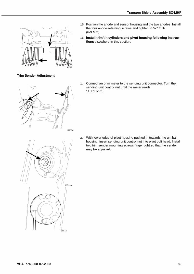
Transom Shield Assembly SX-MHP
15. Position the anode and sensor housing and the two anodes. Install the four anode retaining screws and tighten to 5-7 ft. lb. (6-9 N•m).
16. Install trim/tilt cylinders and pivot housing following instruc-tions elsewhere in this section.
Trim Sender Adjustment
1. Connect an ohm meter to the sending unit connector. Turn the sending unit control nut until the meter reads 11 ± 1 ohm.
2. With lower edge of pivot housing pushed in towards the gimbal housing, insert sending unit control nut into pivot bolt head. Install two trim sender mounting screws finger tight so that the sender may be adjusted.
48697
19766A
19513A
19514
VPA 7743008 07-2003 69
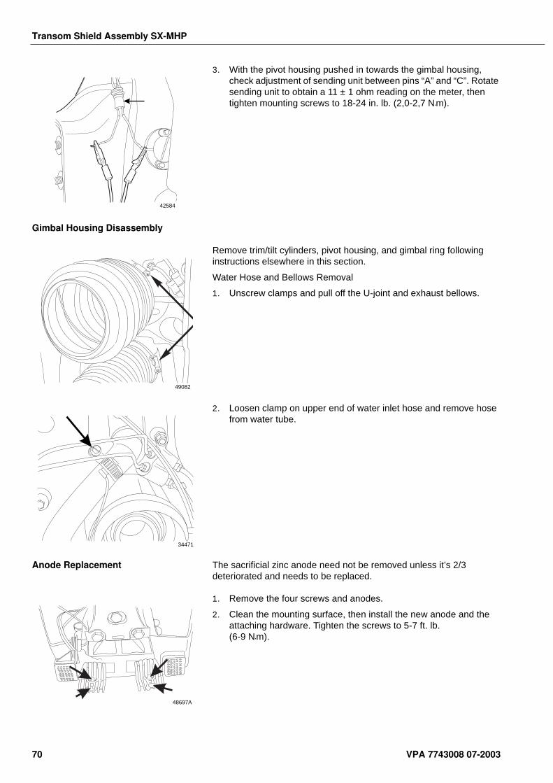
Transom Shield Assembly SX-MHP
3. With the pivot housing pushed in towards the gimbal housing, check adjustment of sending unit between pins “A” and “C”. Rotate sending unit to obtain a 11 ± 1 ohm reading on the meter, then tighten mounting screws to 18-24 in. lb. (2,0-2,7 N•m).
Gimbal Housing Disassembly
Remove trim/tilt cylinders, pivot housing, and gimbal ring following instructions elsewhere in this section.
Water Hose and Bellows Removal
1. Unscrew clamps and pull off the U-joint and exhaust bellows.
2. Loosen clamp on upper end of water inlet hose and remove hose from water tube.
Anode Replacement The sacrificial zinc anode need not be removed unless it’s 2/3 deteriorated and needs to be replaced.
1. Remove the four screws and anodes.
2. Clean the mounting surface, then install the new anode and the attaching hardware. Tighten the screws to 5-7 ft. lb. (6-9 N•m).
42584
49082
34471
48697A
70 VPA 7743008 07-2003
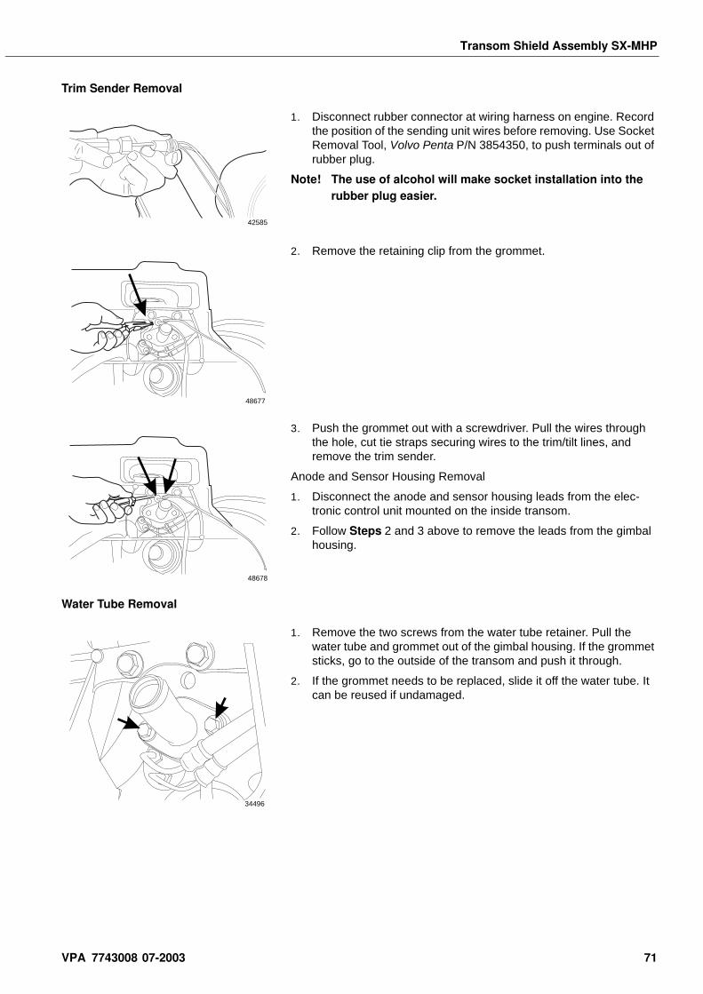
Transom Shield Assembly SX-MHP
Trim Sender Removal
1. Disconnect rubber connector at wiring harness on engine. Record the position of the sending unit wires before removing. Use Socket Removal Tool, Volvo Penta P/N 3854350, to push terminals out of rubber plug.
Note! The use of alcohol will make socket installation into the rubber plug easier.
2. Remove the retaining clip from the grommet.
3. Push the grommet out with a screwdriver. Pull the wires through the hole, cut tie straps securing wires to the trim/tilt lines, and remove the trim sender.
Anode and Sensor Housing Removal
1. Disconnect the anode and sensor housing leads from the elec-tronic control unit mounted on the inside transom.
2. Follow Steps 2 and 3 above to remove the leads from the gimbal housing.
Water Tube Removal
1. Remove the two screws from the water tube retainer. Pull the water tube and grommet out of the gimbal housing. If the grommet sticks, go to the outside of the transom and push it through.
2. If the grommet needs to be replaced, slide it off the water tube. It can be reused if undamaged.
42585
48677
48678
34496
VPA 7743008 07-2003 71
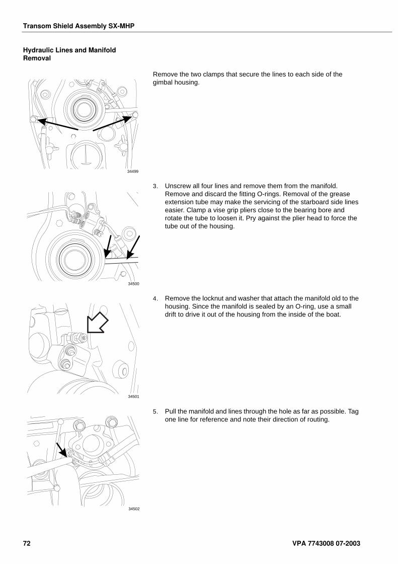
Transom Shield Assembly SX-MHP
Hydraulic Lines and Manifold Removal
Remove the two clamps that secure the lines to each side of the gimbal housing.
3. Unscrew all four lines and remove them from the manifold. Remove and discard the fitting O-rings. Removal of the grease extension tube may make the servicing of the starboard side lines easier. Clamp a vise grip pliers close to the bearing bore and rotate the tube to loosen it. Pry against the plier head to force the tube out of the housing.
4. Remove the locknut and washer that attach the manifold old to the housing. Since the manifold is sealed by an O-ring, use a small drift to drive it out of the housing from the inside of the boat.
5. Pull the manifold and lines through the hole as far as possible. Tag one line for reference and note their direction of routing.
34499
34500
34501
34502
72 VPA 7743008 07-2003
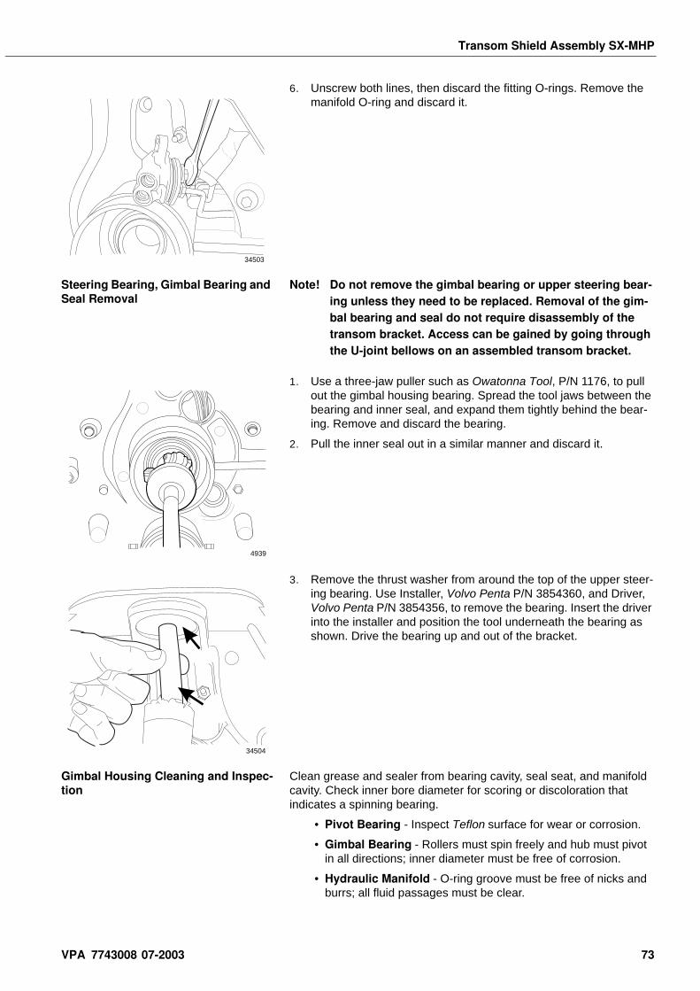
Transom Shield Assembly SX-MHP
6. Unscrew both lines, then discard the fitting O-rings. Remove the manifold O-ring and discard it.
Steering Bearing, Gimbal Bearing and Seal Removal
Note! Do not remove the gimbal bearing or upper steering bear-ing unless they need to be replaced. Removal of the gim-bal bearing and seal do not require disassembly of the transom bracket. Access can be gained by going through the U-joint bellows on an assembled transom bracket.
1. Use a three-jaw puller such as Owatonna Tool, P/N 1176, to pull out the gimbal housing bearing. Spread the tool jaws between the bearing and inner seal, and expand them tightly behind the bear-ing. Remove and discard the bearing.
2. Pull the inner seal out in a similar manner and discard it.
3. Remove the thrust washer from around the top of the upper steer-ing bearing. Use Installer, Volvo Penta P/N 3854360, and Driver, Volvo Penta P/N 3854356, to remove the bearing. Insert the driver into the installer and position the tool underneath the bearing as shown. Drive the bearing up and out of the bracket.
Gimbal Housing Cleaning and Inspec-tion
Clean grease and sealer from bearing cavity, seal seat, and manifold cavity. Check inner bore diameter for scoring or discoloration that indicates a spinning bearing.
• Pivot Bearing - Inspect Teflon surface for wear or corrosion.
• Gimbal Bearing - Rollers must spin freely and hub must pivot in all directions; inner diameter must be free of corrosion.
• Hydraulic Manifold - O-ring groove must be free of nicks and burrs; all fluid passages must be clear.
34503
4939
34504
VPA 7743008 07-2003 73
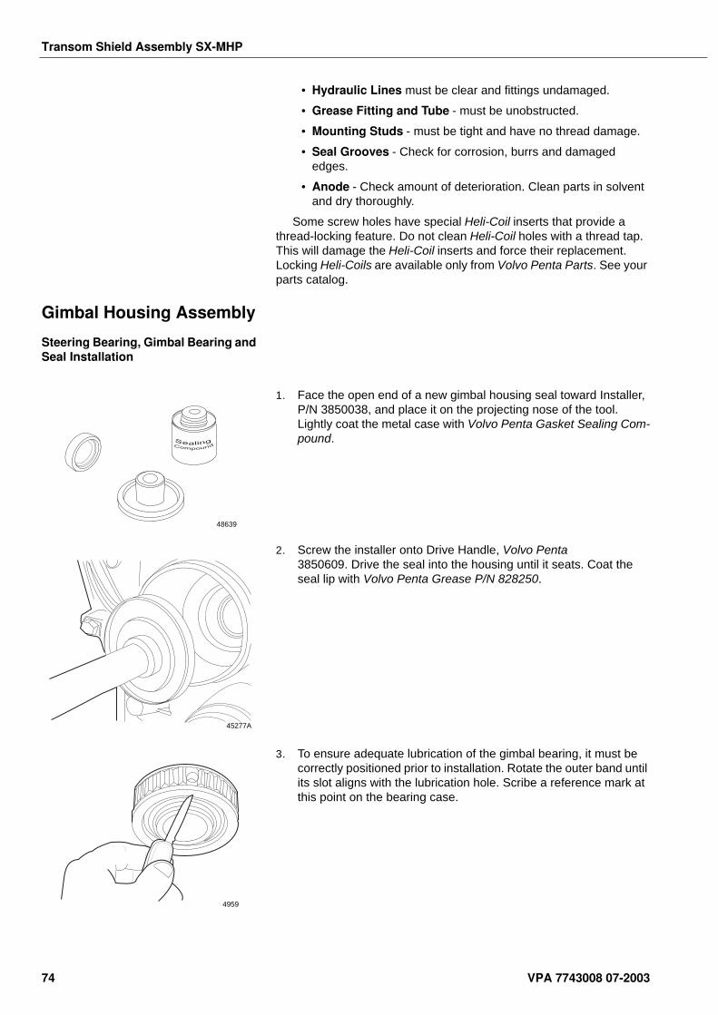
Transom Shield Assembly SX-MHP
• Hydraulic Lines must be clear and fittings undamaged.
• Grease Fitting and Tube - must be unobstructed.
• Mounting Studs - must be tight and have no thread damage.
• Seal Grooves - Check for corrosion, burrs and damaged edges.
• Anode - Check amount of deterioration. Clean parts in solvent and dry thoroughly.
Some screw holes have special Heli-Coil inserts that provide a thread-locking feature. Do not clean Heli-Coil holes with a thread tap. This will damage the Heli-Coil inserts and force their replacement. Locking Heli-Coils are available only from Volvo Penta Parts. See your parts catalog.
Gimbal Housing Assembly
Steering Bearing, Gimbal Bearing and Seal Installation
1. Face the open end of a new gimbal housing seal toward Installer, P/N 3850038, and place it on the projecting nose of the tool. Lightly coat the metal case with Volvo Penta Gasket Sealing Com-pound.
2. Screw the installer onto Drive Handle, Volvo Penta 3850609. Drive the seal into the housing until it seats. Coat the seal lip with Volvo Penta Grease P/N 828250.
3. To ensure adequate lubrication of the gimbal bearing, it must be correctly positioned prior to installation. Rotate the outer band until its slot aligns with the lubrication hole. Scribe a reference mark at this point on the bearing case.
48639
45277A
4959
74 VPA 7743008 07-2003
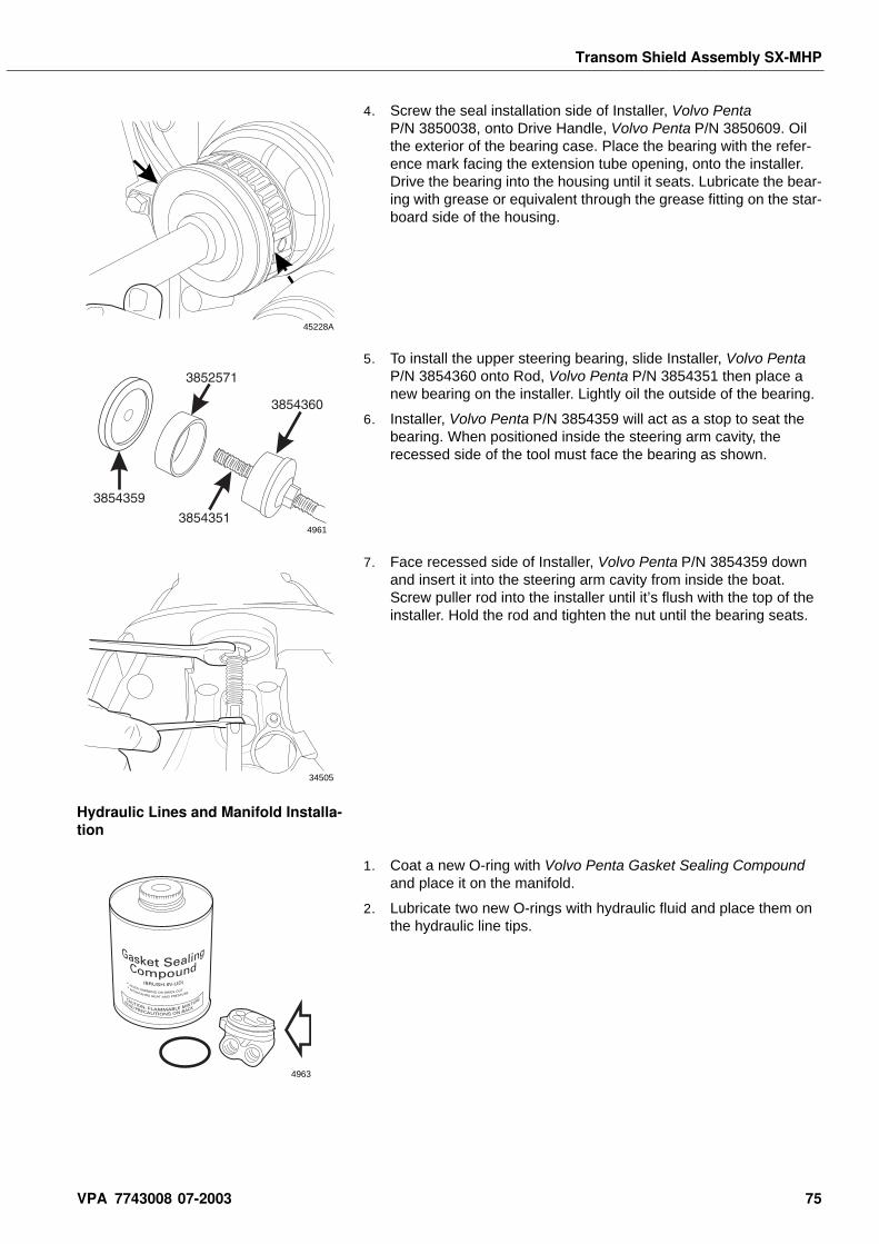
Transom Shield Assembly SX-MHP
4. Screw the seal installation side of Installer, Volvo Penta P/N 3850038, onto Drive Handle, Volvo Penta P/N 3850609. Oil the exterior of the bearing case. Place the bearing with the refer-ence mark facing the extension tube opening, onto the installer. Drive the bearing into the housing until it seats. Lubricate the bear-ing with grease or equivalent through the grease fitting on the star-board side of the housing.
5. To install the upper steering bearing, slide Installer, Volvo Penta P/N 3854360 onto Rod, Volvo Penta P/N 3854351 then place a new bearing on the installer. Lightly oil the outside of the bearing.
6. Installer, Volvo Penta P/N 3854359 will act as a stop to seat the bearing. When positioned inside the steering arm cavity, the recessed side of the tool must face the bearing as shown.
7. Face recessed side of Installer, Volvo Penta P/N 3854359 down and insert it into the steering arm cavity from inside the boat. Screw puller rod into the installer until it’s flush with the top of the installer. Hold the rod and tighten the nut until the bearing seats.
Hydraulic Lines and Manifold Installa-tion
1. Coat a new O-ring with Volvo Penta Gasket Sealing Compound and place it on the manifold.
2. Lubricate two new O-rings with hydraulic fluid and place them on the hydraulic line tips.
45228A
4961
34505
4963
VPA 7743008 07-2003 75
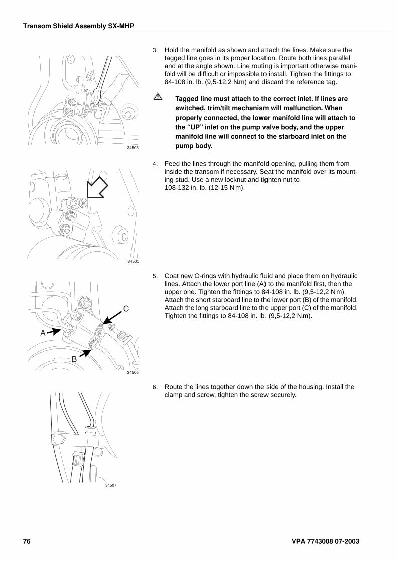
Transom Shield Assembly SX-MHP
3. Hold the manifold as shown and attach the lines. Make sure the tagged line goes in its proper location. Route both lines parallel and at the angle shown. Line routing is important otherwise mani-fold will be difficult or impossible to install. Tighten the fittings to 84-108 in. lb. (9,5-12,2 N•m) and discard the reference tag.
Tagged line must attach to the correct inlet. If lines are switched, trim/tilt mechanism will malfunction. When properly connected, the lower manifold line will attach to the “UP” inlet on the pump valve body, and the upper manifold line will connect to the starboard inlet on the pump body.
4. Feed the lines through the manifold opening, pulling them from inside the transom if necessary. Seat the manifold over its mount-ing stud. Use a new locknut and tighten nut to 108-132 in. lb. (12-15 N•m).
5. Coat new O-rings with hydraulic fluid and place them on hydraulic lines. Attach the lower port line (A) to the manifold first, then the upper one. Tighten the fittings to 84-108 in. lb. (9,5-12,2 N•m). Attach the short starboard line to the lower port (B) of the manifold. Attach the long starboard line to the upper port (C) of the manifold. Tighten the fittings to 84-108 in. lb. (9,5-12,2 N•m).
6. Route the lines together down the side of the housing. Install the clamp and screw, tighten the screw securely.
34503
34501
34506
34507
76 VPA 7743008 07-2003
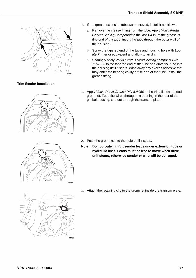
Transom Shield Assembly SX-MHP
7. If the grease extension tube was removed, install it as follows:
a. Remove the grease fitting from the tube. Apply Volvo Penta Gasket Sealing Compound to the last 1/4 in. of the grease fit-ting end of the tube. Insert the tube through the outer wall of the housing.
b. Spray the tapered end of the tube and housing hole with Loc-tite Primer or equivalent and allow to air dry.
c. Sparingly apply Volvo Penta Thread locking compount P/N 1161053 to the tapered end of the tube and drive the tube into the housing until it seats. Wipe away any excess adhesive that may enter the bearing cavity or the end of the tube. Install the grease fitting.
Trim Sender Installation
1. Apply Volvo Penta Grease P/N 828250 to the trim/tilt sender lead grommet. Feed the wires through the opening in the rear of the gimbal housing, and out through the transom plate.
2. Push the grommet into the hole until it seats.
Note! Do not route trim/tilt sender leads under extension tube or hydraulic lines. Leads must be free to move when drive unit steers, otherwise sender or wire will be damaged.
3. Attach the retaining clip to the grommet inside the transom plate.
34508
48684
48685
34467
VPA 7743008 07-2003 77
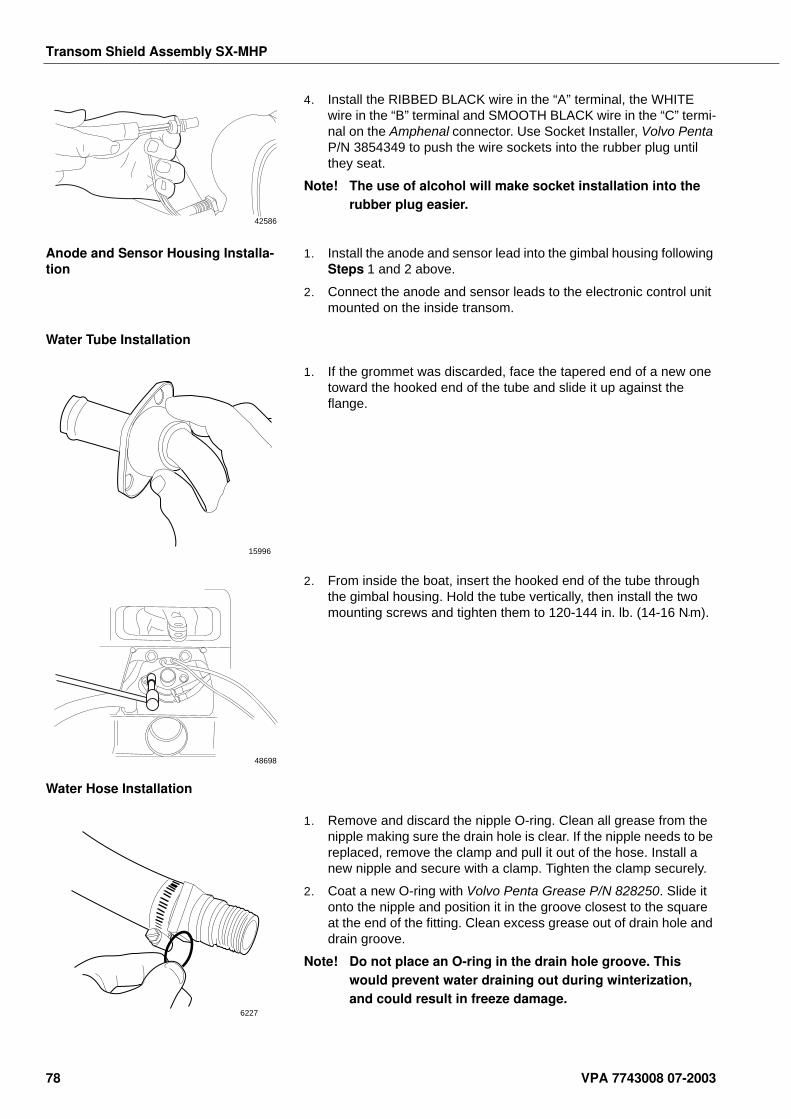
Transom Shield Assembly SX-MHP
4. Install the RIBBED BLACK wire in the “A” terminal, the WHITE wire in the “B” terminal and SMOOTH BLACK wire in the “C” termi-nal on the Amphenal connector. Use Socket Installer, Volvo Penta P/N 3854349 to push the wire sockets into the rubber plug until they seat.
Note! The use of alcohol will make socket installation into the rubber plug easier.
Anode and Sensor Housing Installa-tion
1. Install the anode and sensor lead into the gimbal housing following Steps 1 and 2 above.
2. Connect the anode and sensor leads to the electronic control unit mounted on the inside transom.
Water Tube Installation
1. If the grommet was discarded, face the tapered end of a new one toward the hooked end of the tube and slide it up against the flange.
2. From inside the boat, insert the hooked end of the tube through the gimbal housing. Hold the tube vertically, then install the two mounting screws and tighten them to 120-144 in. lb. (14-16 N•m).
Water Hose Installation
1. Remove and discard the nipple O-ring. Clean all grease from the nipple making sure the drain hole is clear. If the nipple needs to be replaced, remove the clamp and pull it out of the hose. Install a new nipple and secure with a clamp. Tighten the clamp securely.
2. Coat a new O-ring with Volvo Penta Grease P/N 828250. Slide it onto the nipple and position it in the groove closest to the square at the end of the fitting. Clean excess grease out of drain hole and drain groove.
Note! Do not place an O-ring in the drain hole groove. This would prevent water draining out during winterization, and could result in freeze damage.
42586
15996
48698
6227
78 VPA 7743008 07-2003
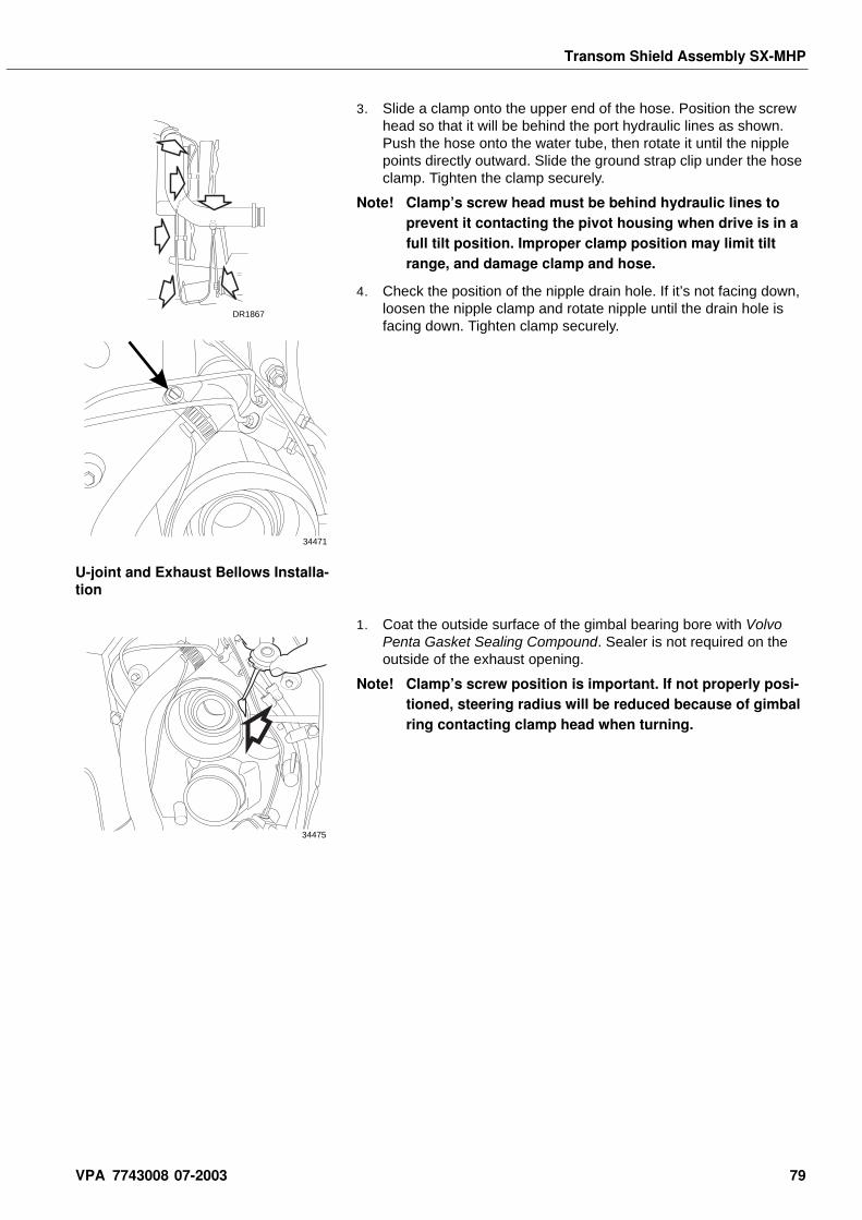
Transom Shield Assembly SX-MHP
3. Slide a clamp onto the upper end of the hose. Position the screw head so that it will be behind the port hydraulic lines as shown. Push the hose onto the water tube, then rotate it until the nipple points directly outward. Slide the ground strap clip under the hose clamp. Tighten the clamp securely.
Note! Clamp’s screw head must be behind hydraulic lines to prevent it contacting the pivot housing when drive is in a full tilt position. Improper clamp position may limit tilt range, and damage clamp and hose.
4. Check the position of the nipple drain hole. If it’s not facing down, loosen the nipple clamp and rotate nipple until the drain hole is facing down. Tighten clamp securely.
U-joint and Exhaust Bellows Installa-tion
1. Coat the outside surface of the gimbal bearing bore with Volvo Penta Gasket Sealing Compound. Sealer is not required on the outside of the exhaust opening.
Note! Clamp’s screw position is important. If not properly posi-tioned, steering radius will be reduced because of gimbal ring contacting clamp head when turning.
DR1867
34471
34475
VPA 7743008 07-2003 79
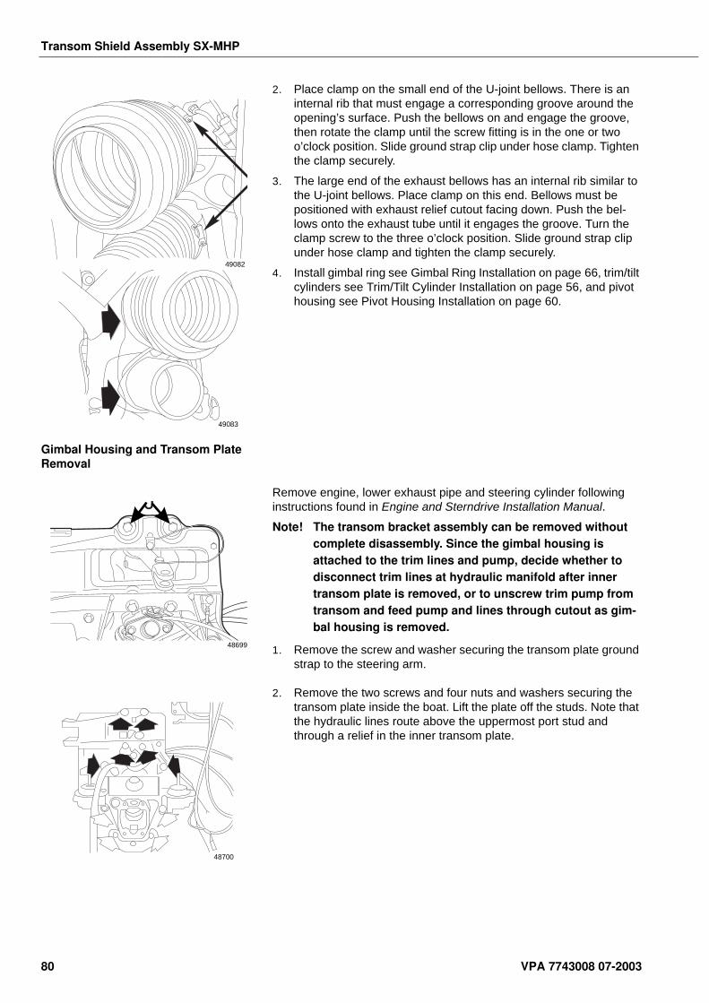
Transom Shield Assembly SX-MHP
2. Place clamp on the small end of the U-joint bellows. There is an internal rib that must engage a corresponding groove around the opening’s surface. Push the bellows on and engage the groove, then rotate the clamp until the screw fitting is in the one or two o’clock position. Slide ground strap clip under hose clamp. Tighten the clamp securely.
3. The large end of the exhaust bellows has an internal rib similar to the U-joint bellows. Place clamp on this end. Bellows must be positioned with exhaust relief cutout facing down. Push the bel-lows onto the exhaust tube until it engages the groove. Turn the clamp screw to the three o’clock position. Slide ground strap clip under hose clamp and tighten the clamp securely.
4. Install gimbal ring see Gimbal Ring Installation on page 66, trim/tilt cylinders see Trim/Tilt Cylinder Installation on page 56, and pivot housing see Pivot Housing Installation on page 60.
Gimbal Housing and Transom Plate Removal
Remove engine, lower exhaust pipe and steering cylinder following instructions found in Engine and Sterndrive Installation Manual.
Note! The transom bracket assembly can be removed without complete disassembly. Since the gimbal housing is attached to the trim lines and pump, decide whether to disconnect trim lines at hydraulic manifold after inner transom plate is removed, or to unscrew trim pump from transom and feed pump and lines through cutout as gim-bal housing is removed.
1. Remove the screw and washer securing the transom plate ground strap to the steering arm.
2. Remove the two screws and four nuts and washers securing the transom plate inside the boat. Lift the plate off the studs. Note that the hydraulic lines route above the uppermost port stud and through a relief in the inner transom plate.
49082
49083
J
48699
48700
80 VPA 7743008 07-2003
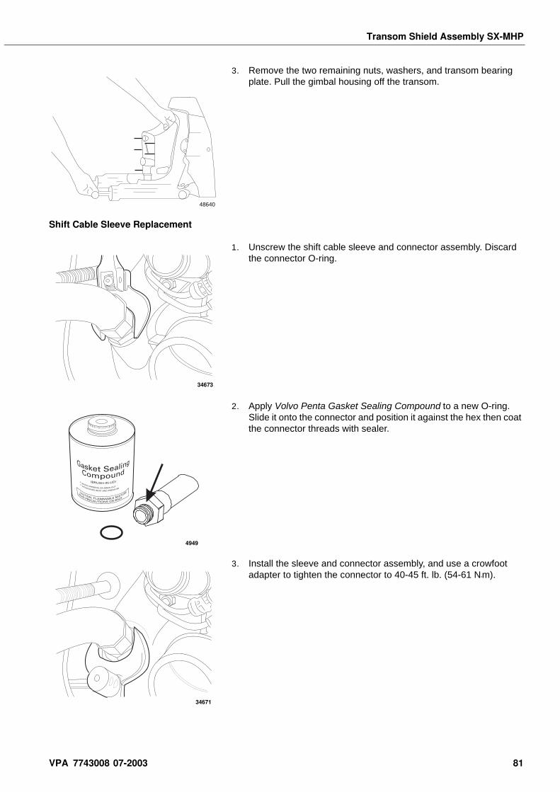
Transom Shield Assembly SX-MHP
3. Remove the two remaining nuts, washers, and transom bearing plate. Pull the gimbal housing off the transom.
Shift Cable Sleeve Replacement
1. Unscrew the shift cable sleeve and connector assembly. Discard the connector O-ring.
2. Apply Volvo Penta Gasket Sealing Compound to a new O-ring. Slide it onto the connector and position it against the hex then coat the connector threads with sealer.
3. Install the sleeve and connector assembly, and use a crowfoot adapter to tighten the connector to 40-45 ft. lb. (54-61 N•m).
48640
34673
4949
34671
VPA 7743008 07-2003 81
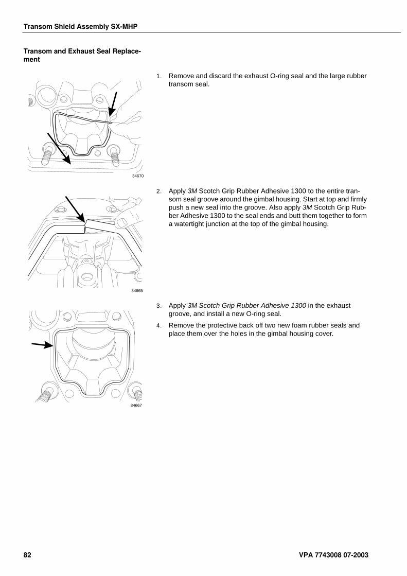
Transom Shield Assembly SX-MHP
Transom and Exhaust Seal Replace-ment
1. Remove and discard the exhaust O-ring seal and the large rubber transom seal.
2. Apply 3M Scotch Grip Rubber Adhesive 1300 to the entire tran-som seal groove around the gimbal housing. Start at top and firmly push a new seal into the groove. Also apply 3M Scotch Grip Rub-ber Adhesive 1300 to the seal ends and butt them together to form a watertight junction at the top of the gimbal housing.
3. Apply 3M Scotch Grip Rubber Adhesive 1300 in the exhaust groove, and install a new O-ring seal.
4. Remove the protective back off two new foam rubber seals and place them over the holes in the gimbal housing cover.
34670
34665
34667
82 VPA 7743008 07-2003
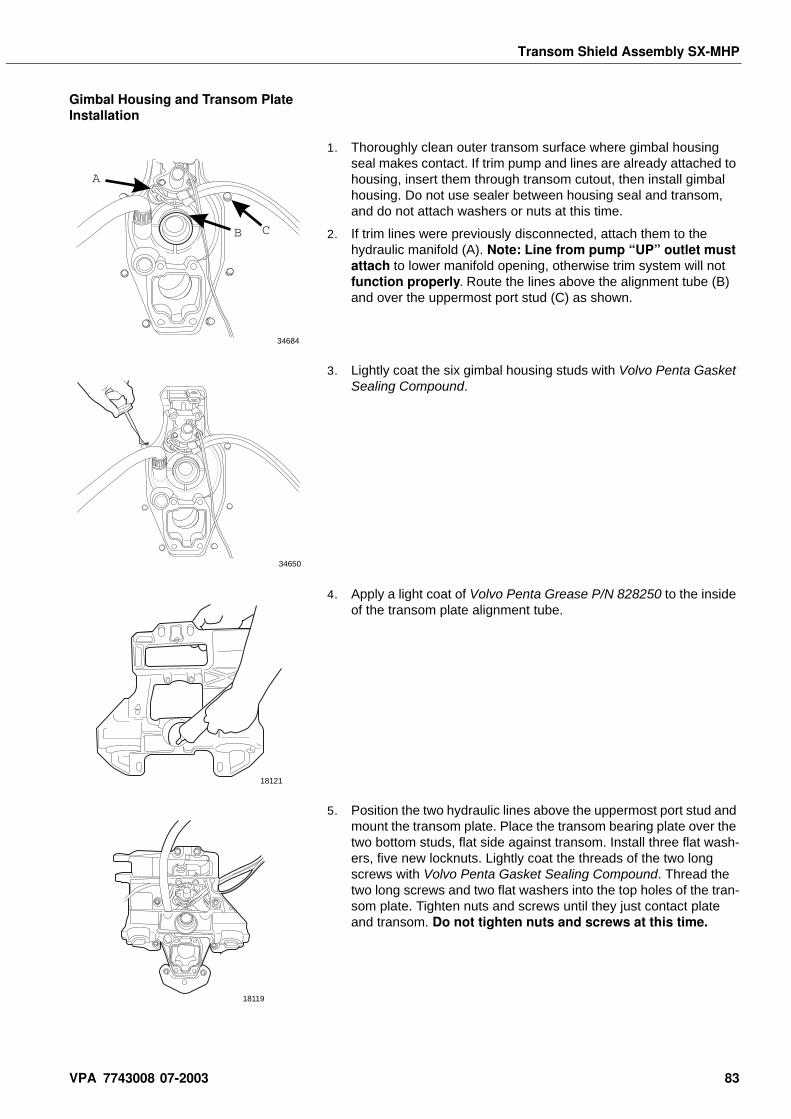
Transom Shield Assembly SX-MHP
Gimbal Housing and Transom Plate Installation
1. Thoroughly clean outer transom surface where gimbal housing seal makes contact. If trim pump and lines are already attached to housing, insert them through transom cutout, then install gimbal housing. Do not use sealer between housing seal and transom, and do not attach washers or nuts at this time.
2. If trim lines were previously disconnected, attach them to the hydraulic manifold (A). Note: Line from pump “UP” outlet must attach to lower manifold opening, otherwise trim system will not function properly. Route the lines above the alignment tube (B) and over the uppermost port stud (C) as shown.
3. Lightly coat the six gimbal housing studs with Volvo Penta Gasket Sealing Compound.
4. Apply a light coat of Volvo Penta Grease P/N 828250 to the inside of the transom plate alignment tube.
5. Position the two hydraulic lines above the uppermost port stud and mount the transom plate. Place the transom bearing plate over the two bottom studs, flat side against transom. Install three flat wash-ers, five new locknuts. Lightly coat the threads of the two long screws with Volvo Penta Gasket Sealing Compound. Thread the two long screws and two flat washers into the top holes of the tran-som plate. Tighten nuts and screws until they just contact plate and transom. Do not tighten nuts and screws at this time.
A
B C
34684
34650
18121
18119
VPA 7743008 07-2003 83
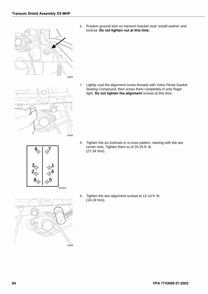
Transom Shield Assembly SX-MHP
6. Position ground wire on transom bracket stud. Install washer and locknut. Do not tighten nut at this time.
7. Lightly coat the alignment screw threads with Volvo Penta Gasket Sealing Compound, then screw them completely in only finger tight. Do not tighten the alignment screws at this time.
8. Tighten the six locknuts in a cross pattern, starting with the two center nuts. Tighten them to of 20-25 ft. lb. (27-34 N•m).
9. Tighten the two alignment screws to 12-14 ft. lb. (16-19 N•m).
34655
34656
6 7
23
8 5
14
DR2955
34658
84 VPA 7743008 07-2003
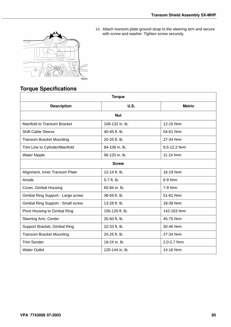
Transom Shield Assembly SX-MHP
10. Attach transom plate ground strap to the steering arm and secure with screw and washer. Tighten screw securely.
Torque Specifications
J
48699
Torque
Description U.S. Metric
Nut
Manifold to Transom Bracket 108-132 in. lb. 12-15 N•m
Shift Cable Sleeve 40-45 ft. lb. 54-61 N•m
Transom Bracket Mounting 20-25 ft. lb. 27-34 N•m
Trim Line to Cylinder/Manifold 84-108 in. lb. 9,5-12,2 N•m
Water Nipple 96-120 in. lb. 11-14 N•m
Screw
Alignment, Inner Transom Plate 12-14 ft. lb. 16-19 N•m
Anode 5-7 ft. lb. 6-9 N•m
Cover, Gimbal Housing 60-84 in. lb. 7-9 N•m
Gimbal Ring Support - Large screw 38-59 ft. lb. 51-81 N•m
Gimbal Ring Support - Small screw 13-28 ft. lb. 18-38 N•m
Pivot Housing to Gimbal Ring 105-120 ft. lb. 142-163 N•m
Steering Arm, Center 35-60 ft. lb. 45-75 N•m
Support Bracket, Gimbal Ring 22-33 ft. lb. 30-46 N•m
Transom Bracket Mounting 20-25 ft. lb. 27-34 N•m
Trim Sender 18-24 in. lb. 2,0-2,7 N•m
Water Outlet 120-144 in. lb. 14-16 N•m
VPA 7743008 07-2003 85
Transom Shield Assembly SX-MHP
Sealants Lubricants, AdhesivesAdhesives
Volvo Penta Thread Locking CompoundP/N 1161053
Stud, Gimbal HousingLubrication TubeStud, Manifold
3M Adhesive Seal, Water PassageSeal Ring, Gimbal Housing Cover
3M Scotch Grip Rubber Adhesive 1300
Seal, Exhaust OpeningTransom Seal
Lubricants
Volvo Penta Grease P/N 828250
Alignment Tube, Inner Transom PlateBushing, Upper Steering PostFriction Washer, Pivot HousingGrommet, Trim Sender LeadNylon Bushing, Trim CylinderO-ring, Upper Steering PostO-ring, Water NipplePivot Pin, Trim/Tilt CylinderSeal Lip, Gimbal HousingThrust Washer, Lower Steering PostThrust Washer, Pivot BoltThrust Washer, Upper Steering Bearing
Marine Wheel Bearing Grease
Gimbal Bearing, Driveshaft
Sealants
Volvo Penta Gasket Sealing Compound P/N 1161099
Alignment Screw, Transom PlateGimbal Housing Lip, U-joint BellowsLubrication TubeO-ring, Hydraulic ManifoldO-ring, Shift Cable TubePivot Housing Lip, U-joint BellowsPivot Pin Threads, Trim/TiltSeal Case, Gimbal HousingStuds, Gimbal Housing
86 VPA 7743008 07-2003
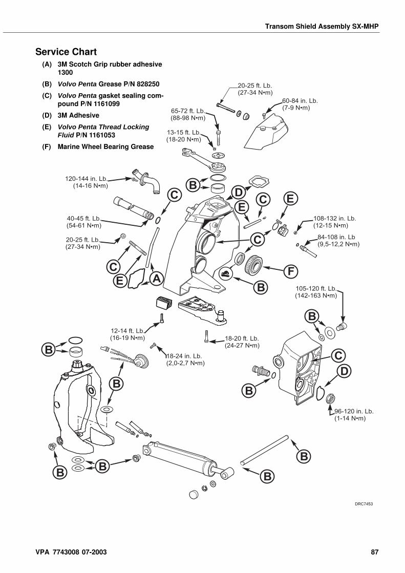
Transom Shield Assembly SX-MHP
Service Chart
E
D
BB
B
B
B
B
B
B
B
B
C
CC
FE A
E
C
C
60-84 in. Lb.(7-9 N•m)
65-72 ft. Lb.(88-98 N•m)
13-15 ft. Lb.(18-20 N•m)
120-144 in. Lb.(14-16 N•m)
20-25 ft. Lb.(27-34 N•m)
40-45 ft. Lb.(54-61 N•m)
108-132 in. Lb.(12-15 N•m)
84-108 in. Lb(9,5-12,2 N•m)
105-120 ft. Lb.(142-163 N•m)
96-120 in. Lb.(1-14 N•m)
18-20 ft. Lb.(24-27 N•m)
18-24 in. Lb.(2,0-2,7 N•m)
12-14 ft. Lb.(16-19 N•m)
D
20-25 ft. Lb.(27-34 N•m)
(A) 3M Scotch Grip rubber adhesive 1300
(B) Volvo Penta Grease P/N 828250
(C) Volvo Penta gasket sealing com-pound P/N 1161099
(D) 3M Adhesive
(E) Volvo Penta Thread Locking Fluid P/N 1161053
(F) Marine Wheel Bearing Grease
DRC7453
VPA 7743008 07-2003 87

Notes
. . . . . . . . . . . . . . . . . . . . . . . . . . . . . . . . . . . . . . . . . . . . . . . . . . . . . . . . . . . . . . . . . . . . . . . . . . . . . . . . . . . . . . .. . . . . . . . . . . . . . . . . . . . . . . . . . . . . . . . . . . . . . . . . . . . . . . . . . . . . . . . . . . . . . . . . . . . . . . . . . . . . . . . . . . . . . .
. . . . . . . . . . . . . . . . . . . . . . . . . . . . . . . . . . . . . . . . . . . . . . . . . . . . . . . . . . . . . . . . . . . . . . . . . . . . . . . . . . . . . . .
. . . . . . . . . . . . . . . . . . . . . . . . . . . . . . . . . . . . . . . . . . . . . . . . . . . . . . . . . . . . . . . . . . . . . . . . . . . . . . . . . . . . . . .
. . . . . . . . . . . . . . . . . . . . . . . . . . . . . . . . . . . . . . . . . . . . . . . . . . . . . . . . . . . . . . . . . . . . . . . . . . . . . . . . . . . . . . .
. . . . . . . . . . . . . . . . . . . . . . . . . . . . . . . . . . . . . . . . . . . . . . . . . . . . . . . . . . . . . . . . . . . . . . . . . . . . . . . . . . . . . . .
. . . . . . . . . . . . . . . . . . . . . . . . . . . . . . . . . . . . . . . . . . . . . . . . . . . . . . . . . . . . . . . . . . . . . . . . . . . . . . . . . . . . . . .
. . . . . . . . . . . . . . . . . . . . . . . . . . . . . . . . . . . . . . . . . . . . . . . . . . . . . . . . . . . . . . . . . . . . . . . . . . . . . . . . . . . . . . .
. . . . . . . . . . . . . . . . . . . . . . . . . . . . . . . . . . . . . . . . . . . . . . . . . . . . . . . . . . . . . . . . . . . . . . . . . . . . . . . . . . . . . . .
. . . . . . . . . . . . . . . . . . . . . . . . . . . . . . . . . . . . . . . . . . . . . . . . . . . . . . . . . . . . . . . . . . . . . . . . . . . . . . . . . . . . . . .
. . . . . . . . . . . . . . . . . . . . . . . . . . . . . . . . . . . . . . . . . . . . . . . . . . . . . . . . . . . . . . . . . . . . . . . . . . . . . . . . . . . . . . .
. . . . . . . . . . . . . . . . . . . . . . . . . . . . . . . . . . . . . . . . . . . . . . . . . . . . . . . . . . . . . . . . . . . . . . . . . . . . . . . . . . . . . . .
. . . . . . . . . . . . . . . . . . . . . . . . . . . . . . . . . . . . . . . . . . . . . . . . . . . . . . . . . . . . . . . . . . . . . . . . . . . . . . . . . . . . . . .
. . . . . . . . . . . . . . . . . . . . . . . . . . . . . . . . . . . . . . . . . . . . . . . . . . . . . . . . . . . . . . . . . . . . . . . . . . . . . . . . . . . . . . .
. . . . . . . . . . . . . . . . . . . . . . . . . . . . . . . . . . . . . . . . . . . . . . . . . . . . . . . . . . . . . . . . . . . . . . . . . . . . . . . . . . . . . . .
. . . . . . . . . . . . . . . . . . . . . . . . . . . . . . . . . . . . . . . . . . . . . . . . . . . . . . . . . . . . . . . . . . . . . . . . . . . . . . . . . . . . . . .
. . . . . . . . . . . . . . . . . . . . . . . . . . . . . . . . . . . . . . . . . . . . . . . . . . . . . . . . . . . . . . . . . . . . . . . . . . . . . . . . . . . . . . .
. . . . . . . . . . . . . . . . . . . . . . . . . . . . . . . . . . . . . . . . . . . . . . . . . . . . . . . . . . . . . . . . . . . . . . . . . . . . . . . . . . . . . . .
. . . . . . . . . . . . . . . . . . . . . . . . . . . . . . . . . . . . . . . . . . . . . . . . . . . . . . . . . . . . . . . . . . . . . . . . . . . . . . . . . . . . . . .
. . . . . . . . . . . . . . . . . . . . . . . . . . . . . . . . . . . . . . . . . . . . . . . . . . . . . . . . . . . . . . . . . . . . . . . . . . . . . . . . . . . . . . .
. . . . . . . . . . . . . . . . . . . . . . . . . . . . . . . . . . . . . . . . . . . . . . . . . . . . . . . . . . . . . . . . . . . . . . . . . . . . . . . . . . . . . . .
. . . . . . . . . . . . . . . . . . . . . . . . . . . . . . . . . . . . . . . . . . . . . . . . . . . . . . . . . . . . . . . . . . . . . . . . . . . . . . . . . . . . . . .
. . . . . . . . . . . . . . . . . . . . . . . . . . . . . . . . . . . . . . . . . . . . . . . . . . . . . . . . . . . . . . . . . . . . . . . . . . . . . . . . . . . . . . .
. . . . . . . . . . . . . . . . . . . . . . . . . . . . . . . . . . . . . . . . . . . . . . . . . . . . . . . . . . . . . . . . . . . . . . . . . . . . . . . . . . . . . . .
. . . . . . . . . . . . . . . . . . . . . . . . . . . . . . . . . . . . . . . . . . . . . . . . . . . . . . . . . . . . . . . . . . . . . . . . . . . . . . . . . . . . . . .
. . . . . . . . . . . . . . . . . . . . . . . . . . . . . . . . . . . . . . . . . . . . . . . . . . . . . . . . . . . . . . . . . . . . . . . . . . . . . . . . . . . . . . .
. . . . . . . . . . . . . . . . . . . . . . . . . . . . . . . . . . . . . . . . . . . . . . . . . . . . . . . . . . . . . . . . . . . . . . . . . . . . . . . . . . . . . . .
. . . . . . . . . . . . . . . . . . . . . . . . . . . . . . . . . . . . . . . . . . . . . . . . . . . . . . . . . . . . . . . . . . . . . . . . . . . . . . . . . . . . . . .
. . . . . . . . . . . . . . . . . . . . . . . . . . . . . . . . . . . . . . . . . . . . . . . . . . . . . . . . . . . . . . . . . . . . . . . . . . . . . . . . . . . . . . .
. . . . . . . . . . . . . . . . . . . . . . . . . . . . . . . . . . . . . . . . . . . . . . . . . . . . . . . . . . . . . . . . . . . . . . . . . . . . . . . . . . . . . . .
. . . . . . . . . . . . . . . . . . . . . . . . . . . . . . . . . . . . . . . . . . . . . . . . . . . . . . . . . . . . . . . . . . . . . . . . . . . . . . . . . . . . . . .
. . . . . . . . . . . . . . . . . . . . . . . . . . . . . . . . . . . . . . . . . . . . . . . . . . . . . . . . . . . . . . . . . . . . . . . . . . . . . . . . . . . . . . .
. . . . . . . . . . . . . . . . . . . . . . . . . . . . . . . . . . . . . . . . . . . . . . . . . . . . . . . . . . . . . . . . . . . . . . . . . . . . . . . . . . . . . . .
. . . . . . . . . . . . . . . . . . . . . . . . . . . . . . . . . . . . . . . . . . . . . . . . . . . . . . . . . . . . . . . . . . . . . . . . . . . . . . . . . . . . . . .
. . . . . . . . . . . . . . . . . . . . . . . . . . . . . . . . . . . . . . . . . . . . . . . . . . . . . . . . . . . . . . . . . . . . . . . . . . . . . . . . . . . . . . .
. . . . . . . . . . . . . . . . . . . . . . . . . . . . . . . . . . . . . . . . . . . . . . . . . . . . . . . . . . . . . . . . . . . . . . . . . . . . . . . . . . . . . . .
. . . . . . . . . . . . . . . . . . . . . . . . . . . . . . . . . . . . . . . . . . . . . . . . . . . . . . . . . . . . . . . . . . . . . . . . . . . . . . . . . . . . . . .
Upper Gear Housing
Upper Gear HousingTable of Contents Special Tools . . . . . . . . . . . . . . . . . . . . . . . . . . . . . . . . . . . . . . 96
Sealants, Lubricants and Adhesives . . . . . . . . . . . . . . . . . . . 96Sterndrive Removal . . . . . . . . . . . . . . . . . . . . . . . . . . . . . . . . . 97
Sterndrive Disassembly . . . . . . . . . . . . . . . . . . . . . . . 97Upper Gear Housing Disassembly. . . . . . . . . . . . . . . . . . . . . 98Shift Actuator Housing Removal . . . . . . . . . . . . . . . . . . . . . . 99Pinion Bearing Carrier Removal. . . . . . . . . . . . . . . . . . . . . . . 99Output Gear Removal . . . . . . . . . . . . . . . . . . . . . . . . . . . . . . 100Upper and Lower Output Gear Disassembly . . . . . . . . . . . 103U-joint Replacement . . . . . . . . . . . . . . . . . . . . . . . . . . . . . . . 104U-Joint Installation . . . . . . . . . . . . . . . . . . . . . . . . . . . . . . . . 105Pinion Bearing Carrier Disassembly . . . . . . . . . . . . . . . . . . 106Upper Housing Stud Replacement. . . . . . . . . . . . . . . . . . . . 109Upper Gear Housing Oil Screen . . . . . . . . . . . . . . . . . . . . . . 109Shimming Thrust Plates . . . . . . . . . . . . . . . . . . . . . . . . . . . . 109Shift Linkage Disassembly . . . . . . . . . . . . . . . . . . . . . . . . . . 111Water Passage Plate Service . . . . . . . . . . . . . . . . . . . . . . . . 112Shift Linkage Assembly . . . . . . . . . . . . . . . . . . . . . . . . . . . . 112Pinion Bearing Carrier Assembly. . . . . . . . . . . . . . . . . . . . . 113Upper and Lower Output Gears Assembly . . . . . . . . . . . . . 118Lower Output Gear Shimming . . . . . . . . . . . . . . . . . . . . . . . 119Upper Output Gear Shimming . . . . . . . . . . . . . . . . . . . . . . . 120Pinion Bearing Carrier Shimming . . . . . . . . . . . . . . . . . . . . 120
Upper Gear Housing Assembly . . . . . . . . . . . . . . . . 121Lower Output Gear and Shaft Assembly. . . . . . . . . . . . . . . 121Lower Output Gear Installation . . . . . . . . . . . . . . . . . . . . . . 123Cone Clutch Installation . . . . . . . . . . . . . . . . . . . . . . . . . . . . 125Upper Output Gear Installation . . . . . . . . . . . . . . . . . . . . . . 126Shimming Vertical Movement Of Upper Driveshaft . . . . . . 127Pinion Bearing Carrier Installation. . . . . . . . . . . . . . . . . . . . 128Top Cover Shimming. . . . . . . . . . . . . . . . . . . . . . . . . . . . . . . 129Checking Gear Lash . . . . . . . . . . . . . . . . . . . . . . . . . . . . . . . 129Lower Gear . . . . . . . . . . . . . . . . . . . . . . . . . . . . . . . . . . . . . . . 130Correcting Gear Lash . . . . . . . . . . . . . . . . . . . . . . . . . . . . . . 131Checking the Gear Teeth Contact Pattern. . . . . . . . . . . . . . 134Final Assembly of Upper Gear Housing . . . . . . . . . . . . . . . 135Shift Actuator Housing Disassembly. . . . . . . . . . . . . . . . . . 136Shift Actuator Housing Assembly . . . . . . . . . . . . . . . . . . . . 138Shift Actuator Housing Installation . . . . . . . . . . . . . . . . . . . 140Shimming Shift Actuator Housing . . . . . . . . . . . . . . . . . . . . 140Assembly of Sterndrive. . . . . . . . . . . . . . . . . . . . . . . . . . . . . 142Pressure and Vacuum Testing Sterndrive . . . . . . . . . . . . . 143Pressure Testing . . . . . . . . . . . . . . . . . . . . . . . . . . . . . . . . . . 144Sterndrive Filling . . . . . . . . . . . . . . . . . . . . . . . . . . . . . . . . . . 144
Specifications . . . . . . . . . . . . . . . . . . . . . . . . . . . . . . 148Sealants, Lubricants and Adhesives . . . . . . . . . . . 149Service Chart . . . . . . . . . . . . . . . . . . . . . . . . . . . . . . 150
Safety Warnings Before beginning work in this section, read Safety chapter at end of this manual. When replacement parts are required, use genuine Volvo Penta. Failure to do so may result in product malfunction and possible injury to the operator and/or passengers. Several of the following procedures require use of an arbor or hydraulic press. Always wear safety glasses when using this device to perform these procedures.
VPA 7743008 07-2003 89
Upper Gear Housing
Special Tools
Owatonna Service Tools OEM 4635 universal joint ToolOEM 1027 Universal Dial Indicator Set
Order From: OTC Division of SPX Corporation
655 Eisenhower Drive
Owatonna, Minnesota 55060 USA
Toll free order line: 1-800-533-0492 or 1-800-533-5338
http://www.otctools.com
Sealants, Lubricants and Adhesives Cleaning Solvent
GL5 Synthetic gear lubricant
Volvo Penta Gasket Sealing Compound
Loctite Primer
Volvo Penta Thread locking compount P/N 1161053
Volvo Penta Grease P/N 828250
3M Adhesive
Wheel Bearing Grease gear lubricant
Tool Name Volvo Penta P/N
Panel Location
Assembly Tool 884932 F
Bracket Assembly 3850057 J
Disassembly Tool 884933 F
Drift 884168 F
Drift 884259 F
Drift 884263 F
Drift 884266 F
Remover/Installer 3850606 H
Retaining Ring Pliers 3850608 B
Seal Installer 3850607 H
Shim Tool 3850600 H
Shim Tool 3850701 H
Sleeve 884938 F
Spanner Wrench 3850604 H
Spline Socket 3850598 H
Standard Shaft 9991801 H
universal joint Adaptor Kit 3850628 G
Upper Gear Housing Holder 3856163 **
** Not located on tool board because of size.
90 VPA 7743008 07-2003
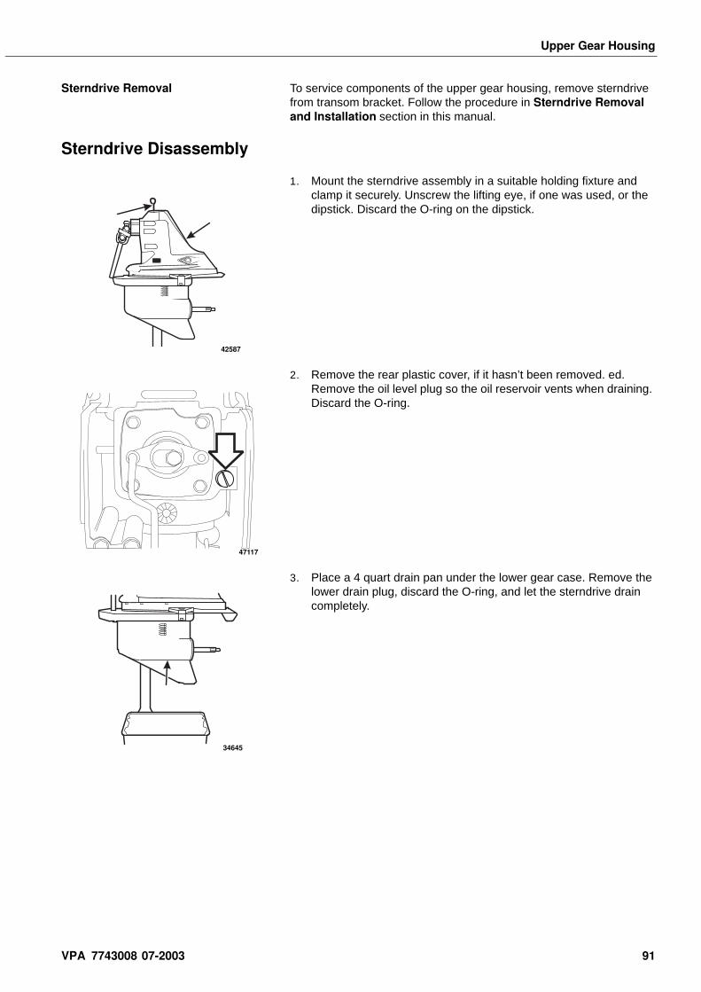
Upper Gear Housing
Sterndrive Removal To service components of the upper gear housing, remove sterndrive from transom bracket. Follow the procedure in Sterndrive Removal and Installation section in this manual.
Sterndrive Disassembly
1. Mount the sterndrive assembly in a suitable holding fixture and clamp it securely. Unscrew the lifting eye, if one was used, or the dipstick. Discard the O-ring on the dipstick.
2. Remove the rear plastic cover, if it hasn’t been removed. ed. Remove the oil level plug so the oil reservoir vents when draining. Discard the O-ring.
3. Place a 4 quart drain pan under the lower gear case. Remove the lower drain plug, discard the O-ring, and let the sterndrive drain completely.
42587
47117
34645
VPA 7743008 07-2003 91
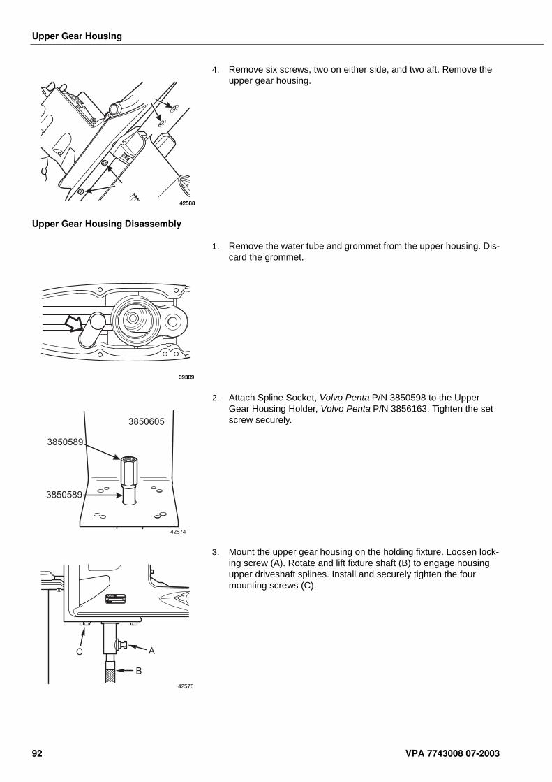
Upper Gear Housing
4. Remove six screws, two on either side, and two aft. Remove the upper gear housing.
Upper Gear Housing Disassembly
1. Remove the water tube and grommet from the upper housing. Dis-card the grommet.
2. Attach Spline Socket, Volvo Penta P/N 3850598 to the Upper Gear Housing Holder, Volvo Penta P/N 3856163. Tighten the set screw securely.
3. Mount the upper gear housing on the holding fixture. Loosen lock-ing screw (A). Rotate and lift fixture shaft (B) to engage housing upper driveshaft splines. Install and securely tighten the four mounting screws (C).
42588
39389
3850589
3850589
3850605
42574
C A
B
42576
92 VPA 7743008 07-2003
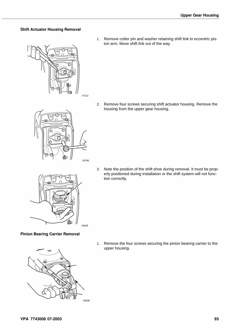
Upper Gear Housing
Shift Actuator Housing Removal
1. Remove cotter pin and washer retaining shift link to eccentric pis-ton arm. Move shift link out of the way.
2. Remove four screws securing shift actuator housing. Remove the housing from the upper gear housing.
3. Note the position of the shift shoe during removal. It must be prop-erly positioned during installation or the shift system will not func-tion correctly.
Pinion Bearing Carrier Removal
1. Remove the four screws securing the pinion bearing carrier to the upper housing.
47112
34766
34639
34638
VPA 7743008 07-2003 93
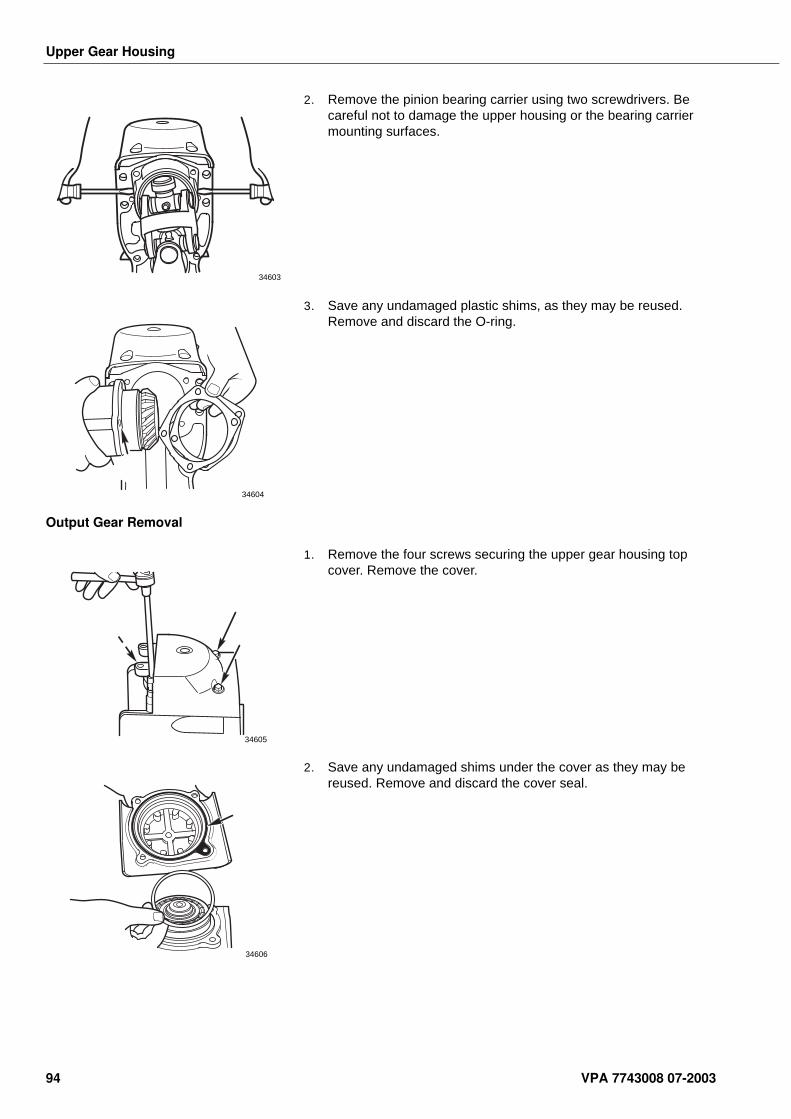
Upper Gear Housing
2. Remove the pinion bearing carrier using two screwdrivers. Be careful not to damage the upper housing or the bearing carrier mounting surfaces.
3. Save any undamaged plastic shims, as they may be reused. Remove and discard the O-ring.
Output Gear Removal
1. Remove the four screws securing the upper gear housing top cover. Remove the cover.
2. Save any undamaged shims under the cover as they may be reused. Remove and discard the cover seal.
34603
34604
34605
34606
94 VPA 7743008 07-2003
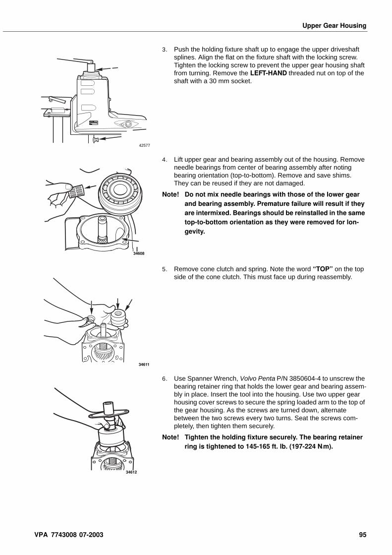
Upper Gear Housing
3. Push the holding fixture shaft up to engage the upper driveshaft splines. Align the flat on the fixture shaft with the locking screw. Tighten the locking screw to prevent the upper gear housing shaft from turning. Remove the LEFT-HAND threaded nut on top of the shaft with a 30 mm socket.
4. Lift upper gear and bearing assembly out of the housing. Remove needle bearings from center of bearing assembly after noting bearing orientation (top-to-bottom). Remove and save shims. They can be reused if they are not damaged.
Note! Do not mix needle bearings with those of the lower gear and bearing assembly. Premature failure will result if they are intermixed. Bearings should be reinstalled in the same top-to-bottom orientation as they were removed for lon-gevity.
5. Remove cone clutch and spring. Note the word “TOP” on the top side of the cone clutch. This must face up during reassembly.
6. Use Spanner Wrench, Volvo Penta P/N 3850604-4 to unscrew the bearing retainer ring that holds the lower gear and bearing assem-bly in place. Insert the tool into the housing. Use two upper gear housing cover screws to secure the spring loaded arm to the top of the gear housing. As the screws are turned down, alternate between the two screws every two turns. Seat the screws com-pletely, then tighten them securely.
Note! Tighten the holding fixture securely. The bearing retainer ring is tightened to 145-165 ft. lb. (197-224 N•m).
42577
34608
34611
34612
VPA 7743008 07-2003 95
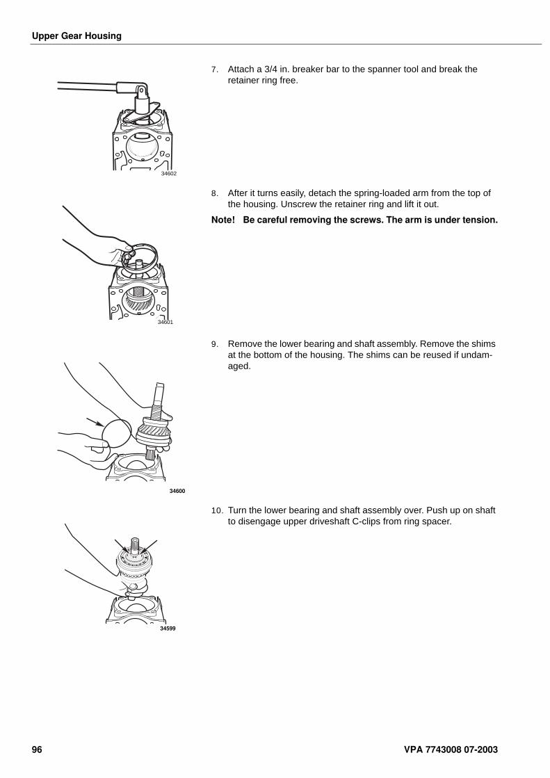
Upper Gear Housing
7. Attach a 3/4 in. breaker bar to the spanner tool and break the retainer ring free.
8. After it turns easily, detach the spring-loaded arm from the top of the housing. Unscrew the retainer ring and lift it out.
Note! Be careful removing the screws. The arm is under tension.
9. Remove the lower bearing and shaft assembly. Remove the shims at the bottom of the housing. The shims can be reused if undam-aged.
10. Turn the lower bearing and shaft assembly over. Push up on shaft to disengage upper driveshaft C-clips from ring spacer.
34602
34601
34600
34599
96 VPA 7743008 07-2003
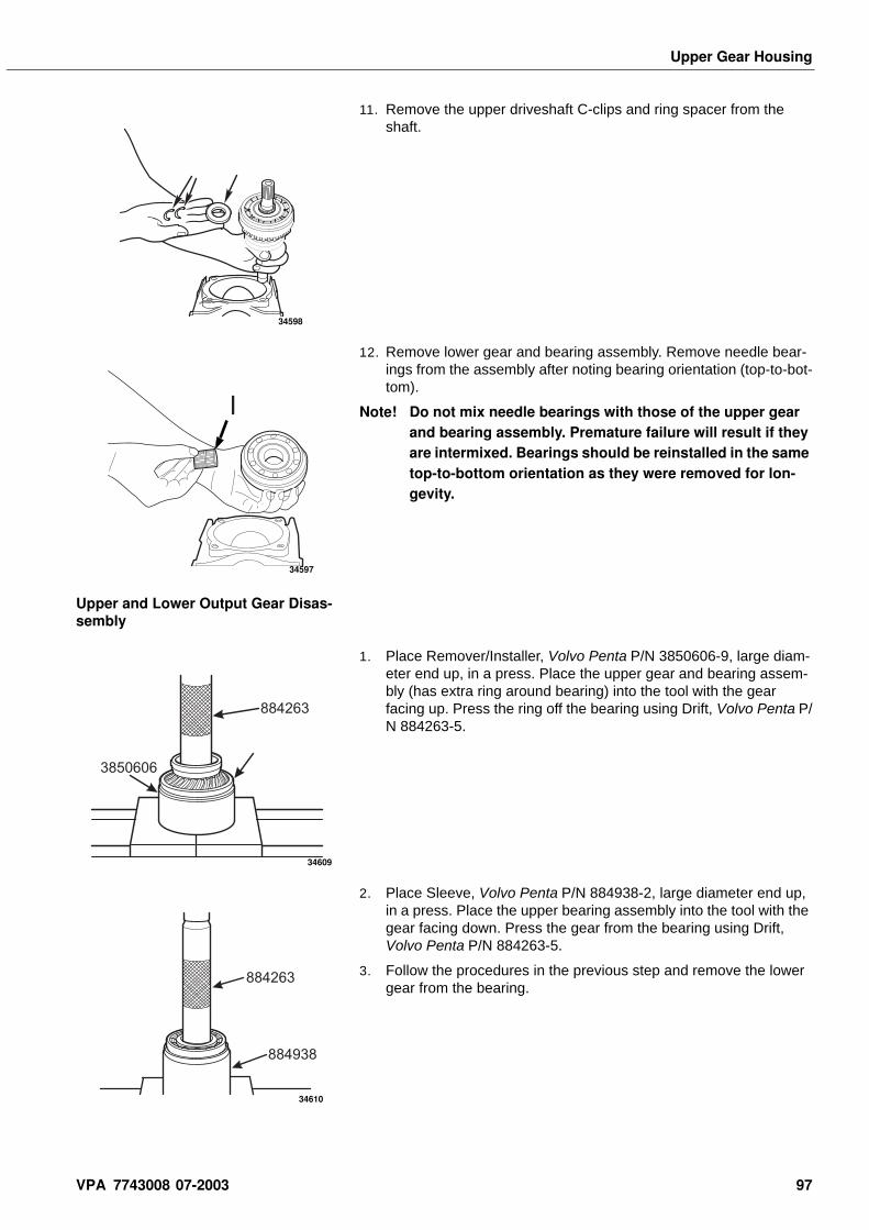
Upper Gear Housing
11. Remove the upper driveshaft C-clips and ring spacer from the shaft.
12. Remove lower gear and bearing assembly. Remove needle bear-ings from the assembly after noting bearing orientation (top-to-bot-tom).
Note! Do not mix needle bearings with those of the upper gear and bearing assembly. Premature failure will result if they are intermixed. Bearings should be reinstalled in the same top-to-bottom orientation as they were removed for lon-gevity.
Upper and Lower Output Gear Disas-sembly
1. Place Remover/Installer, Volvo Penta P/N 3850606-9, large diam-eter end up, in a press. Place the upper gear and bearing assem-bly (has extra ring around bearing) into the tool with the gear facing up. Press the ring off the bearing using Drift, Volvo Penta P/N 884263-5.
2. Place Sleeve, Volvo Penta P/N 884938-2, large diameter end up, in a press. Place the upper bearing assembly into the tool with the gear facing down. Press the gear from the bearing using Drift, Volvo Penta P/N 884263-5.
3. Follow the procedures in the previous step and remove the lower gear from the bearing.
34598
I
34597
3850606
884263
34609
884938
884263
34610
VPA 7743008 07-2003 97
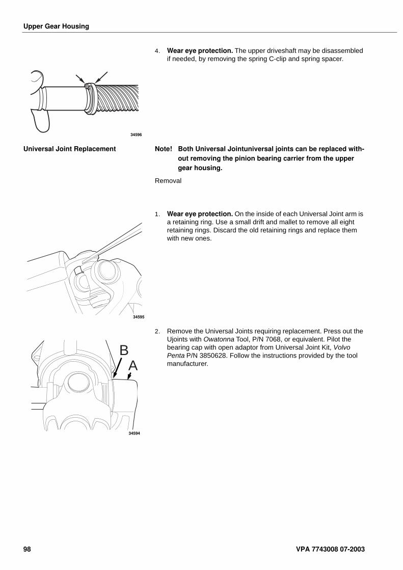
Upper Gear Housing
4. Wear eye protection. The upper driveshaft may be disassembled if needed, by removing the spring C-clip and spring spacer.
Universal Joint Replacement Note! Both Universal Jointuniversal joints can be replaced with-out removing the pinion bearing carrier from the upper gear housing.
Removal
1. Wear eye protection. On the inside of each Universal Joint arm is a retaining ring. Use a small drift and mallet to remove all eight retaining rings. Discard the old retaining rings and replace them with new ones.
2. Remove the Universal Joints requiring replacement. Press out the Ujoints with Owatonna Tool, P/N 7068, or equivalent. Pilot the bearing cap with open adaptor from Universal Joint Kit, Volvo Penta P/N 3850628. Follow the instructions provided by the tool manufacturer.
34596
34595
BA
34594
98 VPA 7743008 07-2003
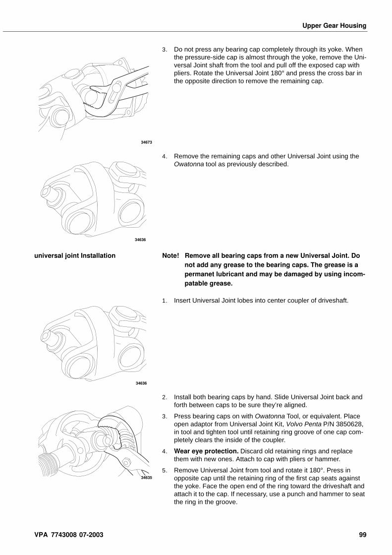
Upper Gear Housing
3. Do not press any bearing cap completely through its yoke. When the pressure-side cap is almost through the yoke, remove the Uni-versal Joint shaft from the tool and pull off the exposed cap with pliers. Rotate the Universal Joint 180° and press the cross bar in the opposite direction to remove the remaining cap.
4. Remove the remaining caps and other Universal Joint using the Owatonna tool as previously described.
universal joint Installation Note! Remove all bearing caps from a new Universal Joint. Do not add any grease to the bearing caps. The grease is a permanet lubricant and may be damaged by using incom-patable grease.
1. Insert Universal Joint lobes into center coupler of driveshaft.
2. Install both bearing caps by hand. Slide Universal Joint back and forth between caps to be sure they’re aligned.
3. Press bearing caps on with Owatonna Tool, or equivalent. Place open adaptor from Universal Joint Kit, Volvo Penta P/N 3850628, in tool and tighten tool until retaining ring groove of one cap com-pletely clears the inside of the coupler.
4. Wear eye protection. Discard old retaining rings and replace them with new ones. Attach to cap with pliers or hammer.
5. Remove Universal Joint from tool and rotate it 180°. Press in opposite cap until the retaining ring of the first cap seats against the yoke. Face the open end of the ring toward the driveshaft and attach it to the cap. If necessary, use a punch and hammer to seat the ring in the groove.
34673
34636
34636
34635
VPA 7743008 07-2003 99
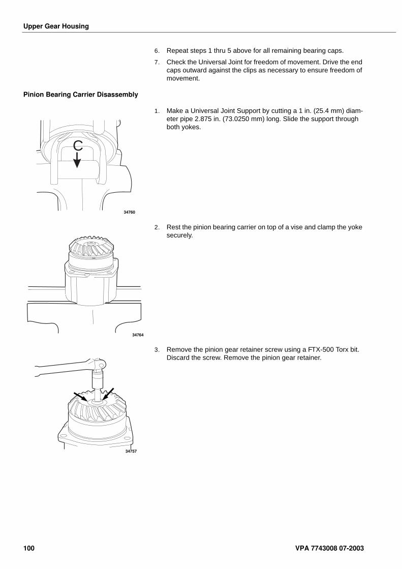
Upper Gear Housing
6. Repeat steps 1 thru 5 above for all remaining bearing caps.
7. Check the Universal Joint for freedom of movement. Drive the end caps outward against the clips as necessary to ensure freedom of movement.
Pinion Bearing Carrier Disassembly
1. Make a Universal Joint Support by cutting a 1 in. (25.4 mm) diam-eter pipe 2.875 in. (73.0250 mm) long. Slide the support through both yokes.
2. Rest the pinion bearing carrier on top of a vise and clamp the yoke securely.
3. Remove the pinion gear retainer screw using a FTX-500 Torx bit. Discard the screw. Remove the pinion gear retainer.
C
34760
34764
34757
100 VPA 7743008 07-2003
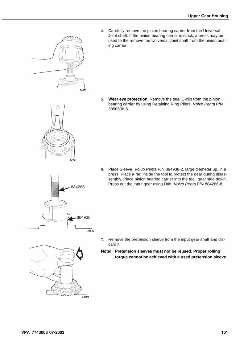
Upper Gear Housing
4. Carefully remove the pinion bearing carrier from the Universal Joint shaft. If the pinion bearing carrier is stuck, a press may be used to the remove the Universal Joint shaft from the pinion bear-ing carrier.
5. Wear eye protection. Remove the seal C-clip from the pinion bearing carrier by using Retaining Ring Pliers, Volvo Penta P/N 3850608-5.
6. Place Sleeve, Volvo Penta P/N 884938-2, large diameter up, in a press. Place a rag inside the tool to protect the gear during disas-sembly. Place pinion bearing carrier into the tool, gear side down. Press out the input gear using Drift, Volvo Penta P/N 884266-8.
7. Remove the pretension sleeve from the input gear shaft and dis-card it.
Note! Pretension sleeves must not be reused. Proper rolling torque cannot be achieved with a used pretension sleeve.
34632
34711
884938
884266
34630
34694
VPA 7743008 07-2003 101
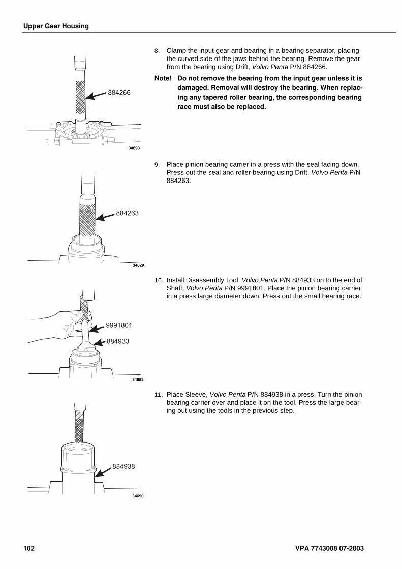
Upper Gear Housing
8. Clamp the input gear and bearing in a bearing separator, placing the curved side of the jaws behind the bearing. Remove the gear from the bearing using Drift, Volvo Penta P/N 884266.
Note! Do not remove the bearing from the input gear unless it is damaged. Removal will destroy the bearing. When replac-ing any tapered roller bearing, the corresponding bearing race must also be replaced.
9. Place pinion bearing carrier in a press with the seal facing down. Press out the seal and roller bearing using Drift, Volvo Penta P/N 884263.
10. Install Disassembly Tool, Volvo Penta P/N 884933 on to the end of Shaft, Volvo Penta P/N 9991801. Place the pinion bearing carrier in a press large diameter down. Press out the small bearing race.
11. Place Sleeve, Volvo Penta P/N 884938 in a press. Turn the pinion bearing carrier over and place it on the tool. Press the large bear-ing out using the tools in the previous step.
884266
34693
884263
34629
884933
9991801
34692
884938
34690
102 VPA 7743008 07-2003
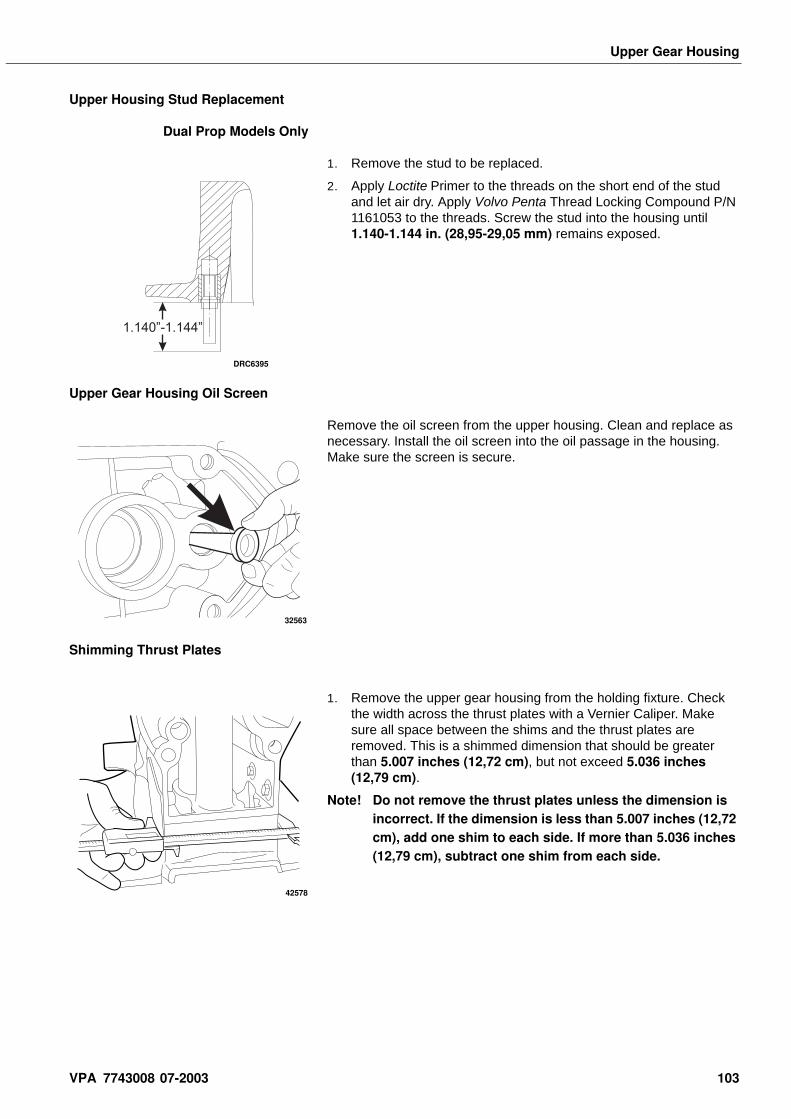
Upper Gear Housing
Upper Housing Stud Replacement
Dual Prop Models Only
1. Remove the stud to be replaced.
2. Apply Loctite Primer to the threads on the short end of the stud and let air dry. Apply Volvo Penta Thread Locking Compound P/N 1161053 to the threads. Screw the stud into the housing until 1.140-1.144 in. (28,95-29,05 mm) remains exposed.
Upper Gear Housing Oil Screen
Remove the oil screen from the upper housing. Clean and replace as necessary. Install the oil screen into the oil passage in the housing. Make sure the screen is secure.
Shimming Thrust Plates
1. Remove the upper gear housing from the holding fixture. Check the width across the thrust plates with a Vernier Caliper. Make sure all space between the shims and the thrust plates are removed. This is a shimmed dimension that should be greater than 5.007 inches (12,72 cm), but not exceed 5.036 inches (12,79 cm).
Note! Do not remove the thrust plates unless the dimension is incorrect. If the dimension is less than 5.007 inches (12,72 cm), add one shim to each side. If more than 5.036 inches (12,79 cm), subtract one shim from each side.
1.140”-1.144”
DRC6395
32563
42578
VPA 7743008 07-2003 103
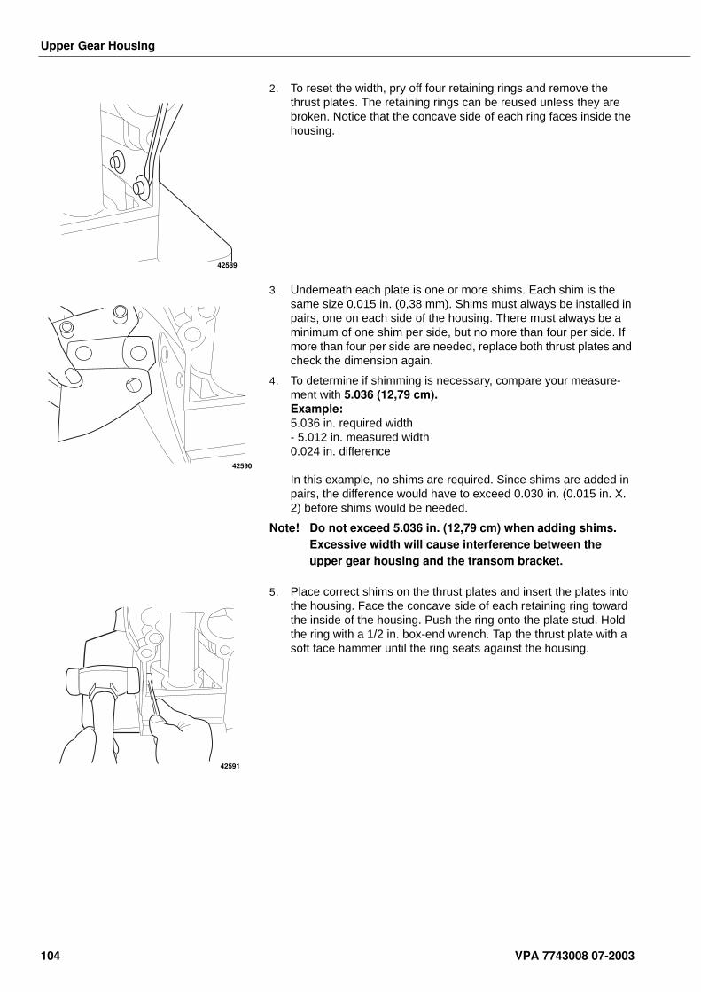
Upper Gear Housing
2. To reset the width, pry off four retaining rings and remove the thrust plates. The retaining rings can be reused unless they are broken. Notice that the concave side of each ring faces inside the housing.
3. Underneath each plate is one or more shims. Each shim is the same size 0.015 in. (0,38 mm). Shims must always be installed in pairs, one on each side of the housing. There must always be a minimum of one shim per side, but no more than four per side. If more than four per side are needed, replace both thrust plates and check the dimension again.
4. To determine if shimming is necessary, compare your measure-ment with 5.036 (12,79 cm). Example: 5.036 in. required width- 5.012 in. measured width 0.024 in. difference
In this example, no shims are required. Since shims are added in pairs, the difference would have to exceed 0.030 in. (0.015 in. X. 2) before shims would be needed.
Note! Do not exceed 5.036 in. (12,79 cm) when adding shims. Excessive width will cause interference between the upper gear housing and the transom bracket.
5. Place correct shims on the thrust plates and insert the plates into the housing. Face the concave side of each retaining ring toward the inside of the housing. Push the ring onto the plate stud. Hold the ring with a 1/2 in. box-end wrench. Tap the thrust plate with a soft face hammer until the ring seats against the housing.
42589
42590
42591
104 VPA 7743008 07-2003
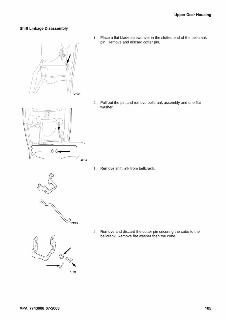
Upper Gear Housing
Shift Linkage Disassembly
1. Place a flat blade screwdriver in the slotted end of the bellcrank pin. Remove and discard cotter pin.
2. Pull out the pin and remove bellcrank assembly and one flat washer.
3. Remove shift link from bellcrank.
4. Remove and discard the cotter pin securing the cube to the bellcrank. Remove flat washer then the cube.
47113
47114
47115a
47116
VPA 7743008 07-2003 105
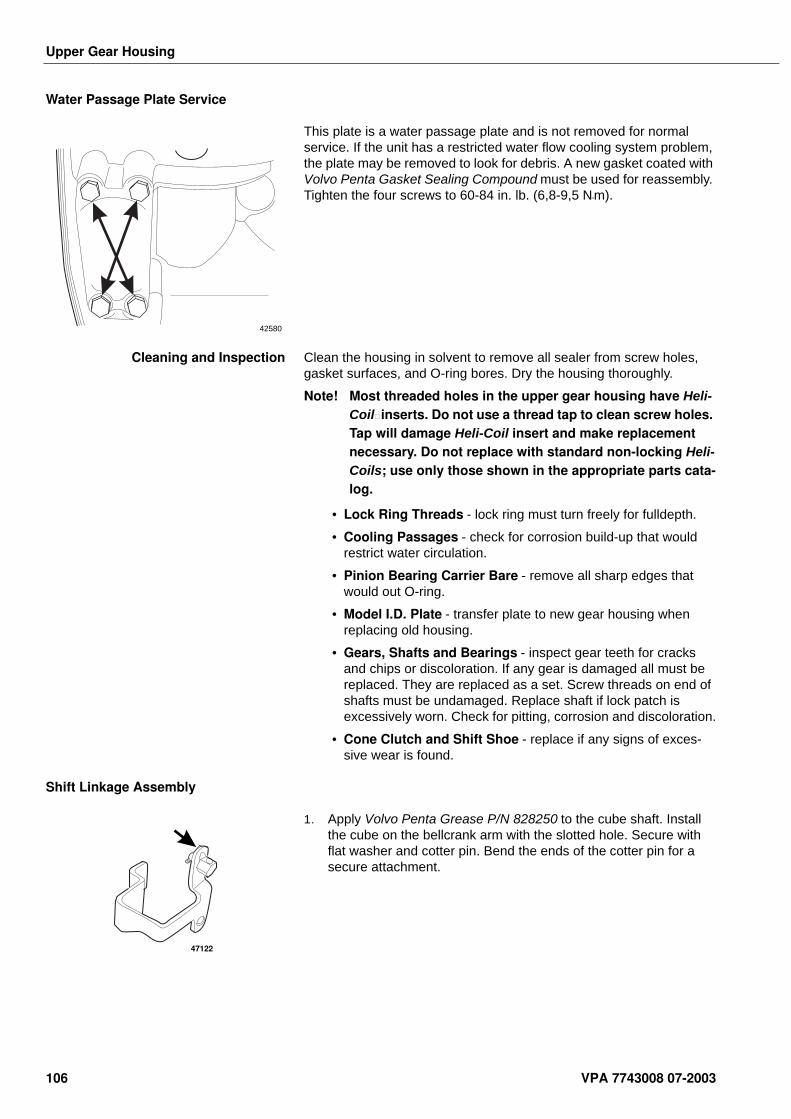
Upper Gear Housing
Water Passage Plate Service
This plate is a water passage plate and is not removed for normal service. If the unit has a restricted water flow cooling system problem, the plate may be removed to look for debris. A new gasket coated with Volvo Penta Gasket Sealing Compound must be used for reassembly. Tighten the four screws to 60-84 in. lb. (6,8-9,5 N•m).
Cleaning and Inspection Clean the housing in solvent to remove all sealer from screw holes, gasket surfaces, and O-ring bores. Dry the housing thoroughly.
Note! Most threaded holes in the upper gear housing have Heli-Coil inserts. Do not use a thread tap to clean screw holes. Tap will damage Heli-Coil insert and make replacement necessary. Do not replace with standard non-locking Heli-Coils; use only those shown in the appropriate parts cata-log.
• Lock Ring Threads - lock ring must turn freely for fulldepth.
• Cooling Passages - check for corrosion build-up that would restrict water circulation.
• Pinion Bearing Carrier Bare - remove all sharp edges that would out O-ring.
• Model I.D. Plate - transfer plate to new gear housing when replacing old housing.
• Gears, Shafts and Bearings - inspect gear teeth for cracks and chips or discoloration. If any gear is damaged all must be replaced. They are replaced as a set. Screw threads on end of shafts must be undamaged. Replace shaft if lock patch is excessively worn. Check for pitting, corrosion and discoloration.
• Cone Clutch and Shift Shoe - replace if any signs of exces-sive wear is found.
Shift Linkage Assembly
1. Apply Volvo Penta Grease P/N 828250 to the cube shaft. Install the cube on the bellcrank arm with the slotted hole. Secure with flat washer and cotter pin. Bend the ends of the cotter pin for a secure attachment.
42580
47122
106 VPA 7743008 07-2003
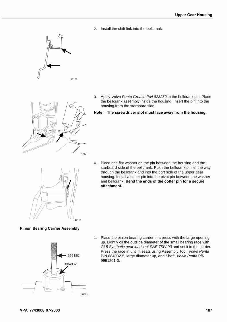
Upper Gear Housing
2. Install the shift link into the bellcrank.
3. Apply Volvo Penta Grease P/N 828250 to the bellcrank pin. Place the bellcrank assembly inside the housing. Insert the pin into the housing from the starboard side.
Note! The screwdriver slot must face away from the housing.
4. Place one flat washer on the pin between the housing and the starboard side of the bellcrank. Push the bellcrank pin all the way through the bellcrank and into the port side of the upper gear housing. Install a cotter pin into the pivot pin between the washer and bellcrank. Bend the ends of the cotter pin for a secure attachment.
Pinion Bearing Carrier Assembly
1. Place the pinion bearing carrier in a press with the large opening up. Lightly oil the outside diameter of the small bearing race with GL5 Synthetic gear lubricant SAE 75W-90 and set it in the carrier. Press the race in until it seats using Assembly Tool, Volvo Penta P/N 884932-5, large diameter up, and Shaft, Volvo Penta P/N 9991801-3.
47123
47124
47113
9991801
884932
34681
VPA 7743008 07-2003 107
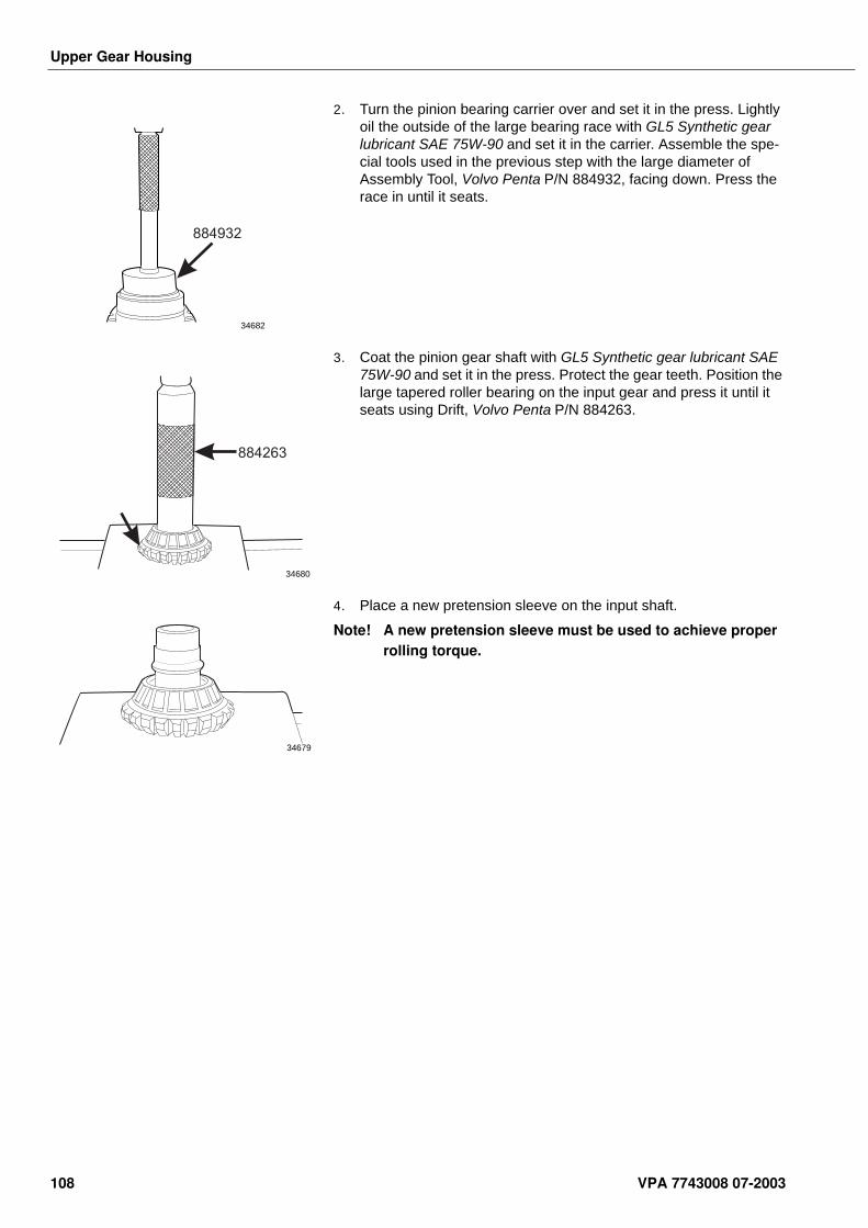
Upper Gear Housing
2. Turn the pinion bearing carrier over and set it in the press. Lightly oil the outside of the large bearing race with GL5 Synthetic gear lubricant SAE 75W-90 and set it in the carrier. Assemble the spe-cial tools used in the previous step with the large diameter of Assembly Tool, Volvo Penta P/N 884932, facing down. Press the race in until it seats.
3. Coat the pinion gear shaft with GL5 Synthetic gear lubricant SAE 75W-90 and set it in the press. Protect the gear teeth. Position the large tapered roller bearing on the input gear and press it until it seats using Drift, Volvo Penta P/N 884263.
4. Place a new pretension sleeve on the input shaft.
Note! A new pretension sleeve must be used to achieve proper rolling torque.
884932
34682
884263
34680
34679
108 VPA 7743008 07-2003
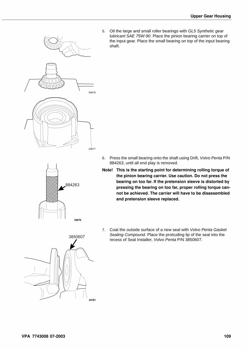
Upper Gear Housing
5. Oil the large and small roller bearings with GL5 Synthetic gear lubricant SAE 75W-90. Place the pinion bearing carrier on top of the input gear. Place the small bearing on top of the input bearing shaft.
6. Press the small bearing onto the shaft using Drift, Volvo Penta P/N 884263, until all end play is removed.
Note! This is the starting point for determining rolling torque of the pinion bearing carrier. Use caution. Do not press the bearing on too far. If the pretension sleeve is distorted by pressing the bearing on too far, proper rolling torque can-not be achieved. The carrier will have to be disassembled and pretension sleeve replaced.
7. Coat the outside surface of a new seal with Volvo Penta Gasket Sealing Compound. Place the protruding lip of the seal into the recess of Seal Installer, Volvo Penta P/N 3850607.
34678
34677
884263
34676
3850607
34761
VPA 7743008 07-2003 109
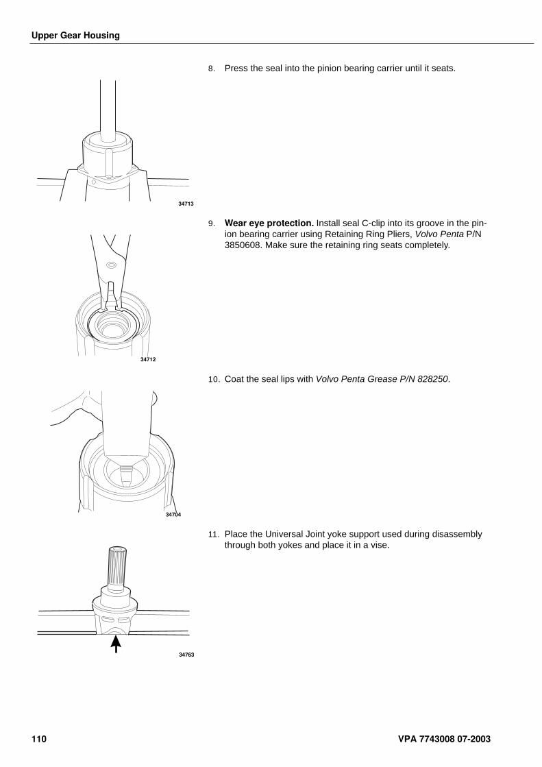
Upper Gear Housing
8. Press the seal into the pinion bearing carrier until it seats.
9. Wear eye protection. Install seal C-clip into its groove in the pin-ion bearing carrier using Retaining Ring Pliers, Volvo Penta P/N 3850608. Make sure the retaining ring seats completely.
10. Coat the seal lips with Volvo Penta Grease P/N 828250.
11. Place the Universal Joint yoke support used during disassembly through both yokes and place it in a vise.
34713
34712
34704
34763
110 VPA 7743008 07-2003
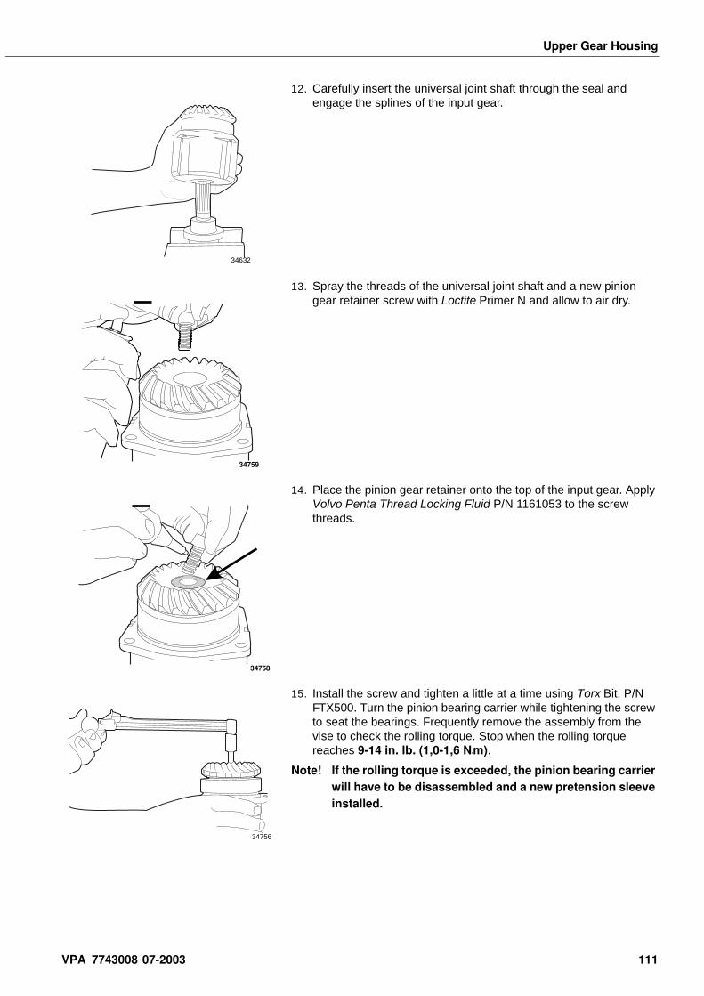
Upper Gear Housing
12. Carefully insert the universal joint shaft through the seal and engage the splines of the input gear.
13. Spray the threads of the universal joint shaft and a new pinion gear retainer screw with Loctite Primer N and allow to air dry.
14. Place the pinion gear retainer onto the top of the input gear. Apply Volvo Penta Thread Locking Fluid P/N 1161053 to the screw threads.
15. Install the screw and tighten a little at a time using Torx Bit, P/N FTX500. Turn the pinion bearing carrier while tightening the screw to seat the bearings. Frequently remove the assembly from the vise to check the rolling torque. Stop when the rolling torque reaches 9-14 in. lb. (1,0-1,6 N•m).
Note! If the rolling torque is exceeded, the pinion bearing carrier will have to be disassembled and a new pretension sleeve installed.
34632
34759
34758
34756
VPA 7743008 07-2003 111
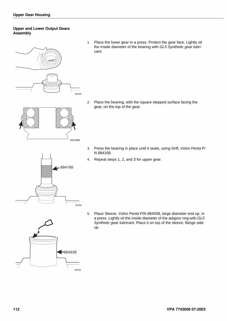
Upper Gear Housing
Upper and Lower Output Gears Assembly
1. Place the lower gear in a press. Protect the gear face. Lightly oil the inside diameter of the bearing with GL5 Synthetic gear lubri-cant.
2. Place the bearing, with the square stepped surface facing the gear, on the top of the gear.
3. Press the bearing in place until it seats, using Drift, Volvo Penta P/N 884168.
4. Repeat steps 1, 2, and 3 for upper gear.
5. Place Sleeve, Volvo Penta P/N 884938, large diameter end up, in a press. Lightly oil the inside diameter of the adaptor ring with GL5 Synthetic gear lubricant. Place it on top of the sleeve, flange side up.
34755
DRC6868
884168
34754
884938
34753
112 VPA 7743008 07-2003
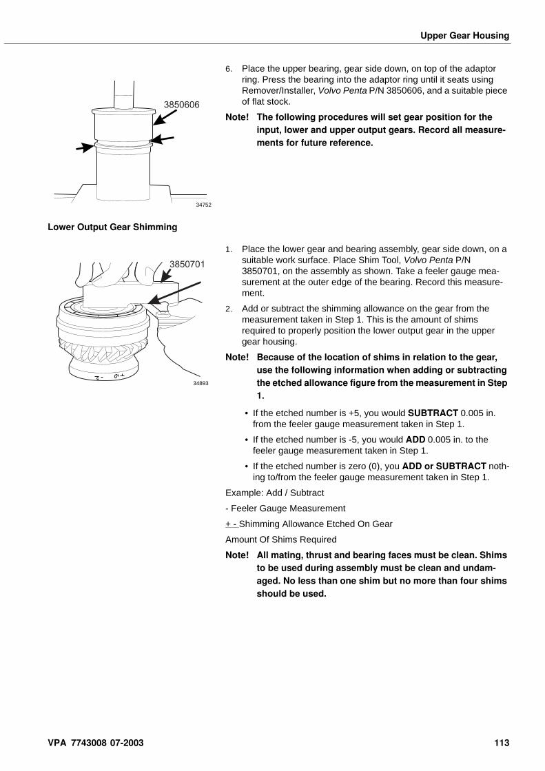
Upper Gear Housing
6. Place the upper bearing, gear side down, on top of the adaptor ring. Press the bearing into the adaptor ring until it seats using Remover/Installer, Volvo Penta P/N 3850606, and a suitable piece of flat stock.
Note! The following procedures will set gear position for the input, lower and upper output gears. Record all measure-ments for future reference.
Lower Output Gear Shimming
1. Place the lower gear and bearing assembly, gear side down, on a suitable work surface. Place Shim Tool, Volvo Penta P/N 3850701, on the assembly as shown. Take a feeler gauge mea-surement at the outer edge of the bearing. Record this measure-ment.
2. Add or subtract the shimming allowance on the gear from the measurement taken in Step 1. This is the amount of shims required to properly position the lower output gear in the upper gear housing.
Note! Because of the location of shims in relation to the gear, use the following information when adding or subtracting the etched allowance figure from the measurement in Step 1.
• If the etched number is +5, you would SUBTRACT 0.005 in. from the feeler gauge measurement taken in Step 1.
• If the etched number is -5, you would ADD 0.005 in. to the feeler gauge measurement taken in Step 1.
• If the etched number is zero (0), you ADD or SUBTRACT noth-ing to/from the feeler gauge measurement taken in Step 1.
Example: Add / Subtract
- Feeler Gauge Measurement
+ - Shimming Allowance Etched On Gear
Amount Of Shims Required
Note! All mating, thrust and bearing faces must be clean. Shims to be used during assembly must be clean and undam-aged. No less than one shim but no more than four shims should be used.
3850606
34752
3850701
34893
VPA 7743008 07-2003 113
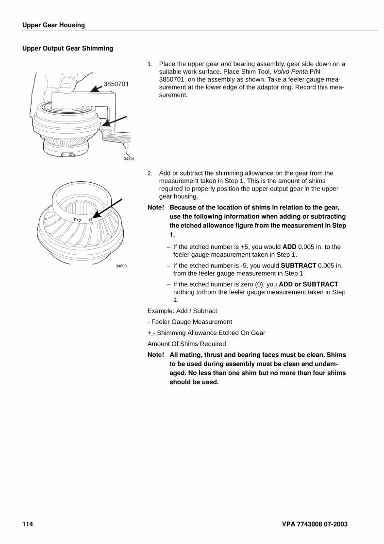
Upper Gear Housing
Upper Output Gear Shimming
1. Place the upper gear and bearing assembly, gear side down on a suitable work surface. Place Shim Tool, Volvo Penta P/N 3850701, on the assembly as shown. Take a feeler gauge mea-surement at the lower edge of the adaptor ring. Record this mea-surement.
2. Add or subtract the shimming allowance on the gear from the measurement taken in Step 1. This is the amount of shims required to properly position the upper output gear in the upper gear housing.
Note! Because of the location of shims in relation to the gear, use the following information when adding or subtracting the etched allowance figure from the measurement in Step 1.
–If the etched number is +5, you would ADD 0.005 in. to the feeler gauge measurement taken in Step 1.
–If the etched number is -5, you would SUBTRACT 0.005 in. from the feeler gauge measurement in Step 1.
–If the etched number is zero (0), you ADD or SUBTRACT nothing to/from the feeler gauge measurement taken in Step 1.
Example: Add / Subtract
- Feeler Gauge Measurement
+ - Shimming Allowance Etched On Gear
Amount Of Shims Required
Note! All mating, thrust and bearing faces must be clean. Shims to be used during assembly must be clean and undam-aged. No less than one shim but no more than four shims should be used.
3850701
34891
34890
114 VPA 7743008 07-2003
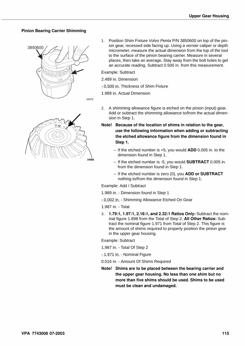
Upper Gear Housing
Pinion Bearing Carrier Shimming
1. Position Shim Fixture Volvo Penta P/N 3850600 on top of the pin-ion gear, recessed side facing up. Using a vernier caliper or depth micrometer, measure the actual dimension from the top of the tool to the surface of the pinion bearing carrier. Measure in several places, then take an average. Stay away from the bolt holes to get an accurate reading. Subtract 0.500 in. from this measurement.
Example: Subtract
2.489 in. Dimension
- 0.500 in. Thickness of Shim Fixture
1.989 in. Actual Dimension
2. A shimming allowance figure is etched on the pinion (input) gear. Add or subtract the shimming allowance to/from the actual dimen-sion in Step 1.
Note! Because of the location of shims in relation to the gear, use the following information when adding or subtracting the etched allowance figure from the dimension found in Step 1.
–If the etched number is +5, you would ADD 0.005 in. to the dimension found in Step 1.
–If the etched number is -5, you would SUBTRACT 0.005 in. from the dimension found in Step 1.
–If the etched number is zero (0), you ADD or SUBTRACT nothing to/from the dimension found in Step 1.
Example: Add / Subtract
1.989 in. - Dimension found in Step 1
- 0.002 in. - Shimming Allowance Etched On Gear
1.987 in. - Total
3. 1.79:1, 1.97:1, 2.18:1, and 2.32:1 Ratios Only: Subtract the nom-inal figure 1.898 from the Total of Step 2. All Other Ratios: Sub-tract the nominal figure 1.971 from Total of Step 2. This figure is the amount of shims required to properly position the pinion gear in the upper gear housing.
Example: Subtract
1.987 in. - Total Of Step 2
- 1.971 in. - Nominal Figure
0.016 in. - Amount Of Shims Required
Note! Shims are to be placed between the bearing carrier and the upper gear housing. No less than one shim but no more than five shims should be used. Shims to be used must be clean and undamaged.
3850600
34978
34888
VPA 7743008 07-2003 115
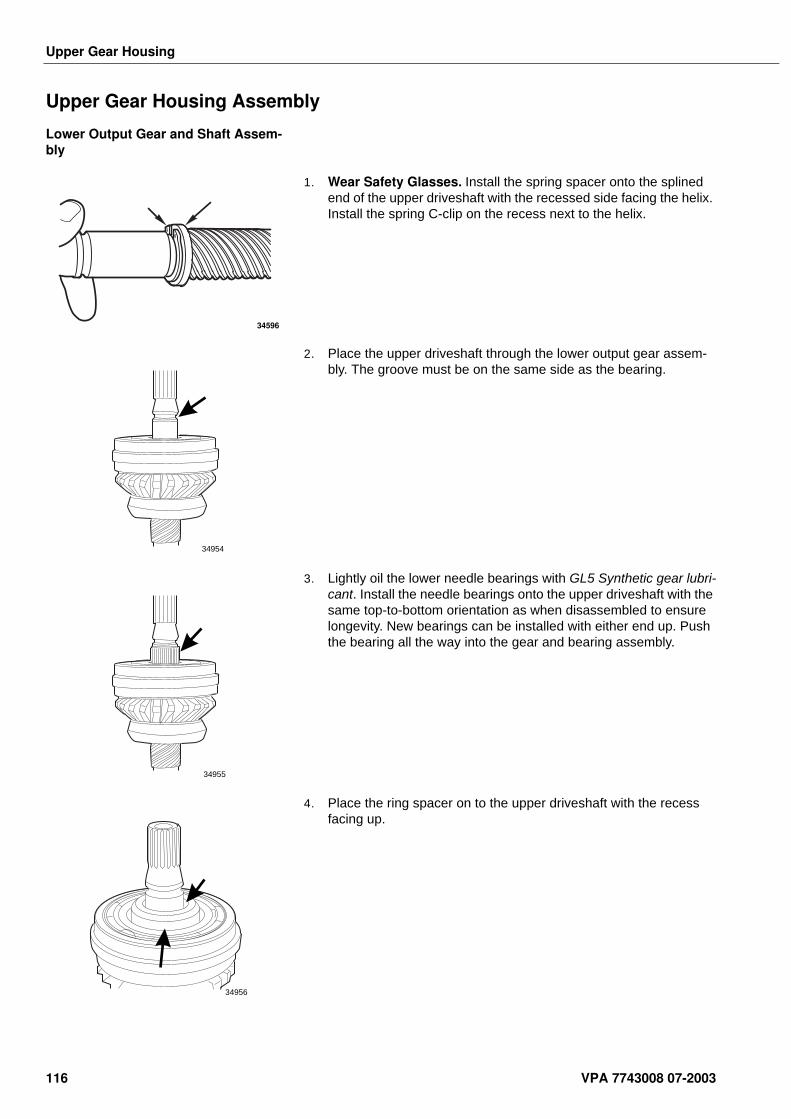
Upper Gear Housing
Upper Gear Housing Assembly
Lower Output Gear and Shaft Assem-bly
1. Wear Safety Glasses. Install the spring spacer onto the splined end of the upper driveshaft with the recessed side facing the helix. Install the spring C-clip on the recess next to the helix.
2. Place the upper driveshaft through the lower output gear assem-bly. The groove must be on the same side as the bearing.
3. Lightly oil the lower needle bearings with GL5 Synthetic gear lubri-cant. Install the needle bearings onto the upper driveshaft with the same top-to-bottom orientation as when disassembled to ensure longevity. New bearings can be installed with either end up. Push the bearing all the way into the gear and bearing assembly.
4. Place the ring spacer on to the upper driveshaft with the recess facing up.
34596
34954
34955
34956
116 VPA 7743008 07-2003

Upper Gear Housing
5. Place the two upper driveshaft C-clips into the groove on the drive-shaft.
6. Move the driveshaft down to capture the C-clips in the recess of the ring spacer.
Lower Output Gear Installation
1. Place the required amount of shims determined in a previous step into the upper gear housing.
2. Rest the shims on the ledge at the bottom of the bore as shown.
34958
34963
34964
VPA 7743008 07-2003 117
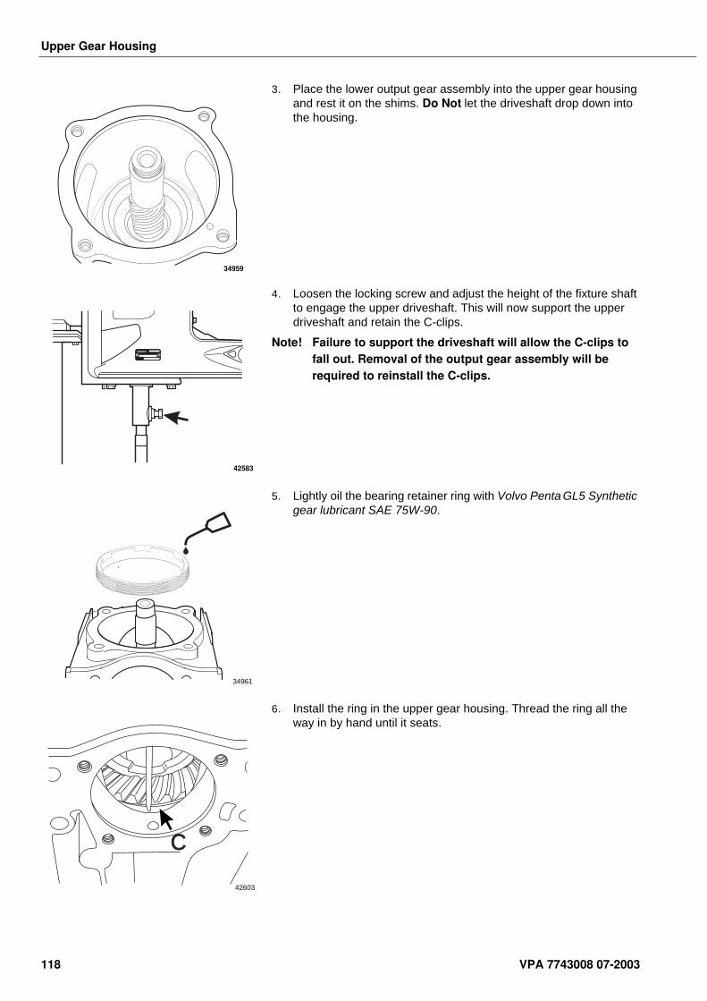
Upper Gear Housing
3. Place the lower output gear assembly into the upper gear housing and rest it on the shims. Do Not let the driveshaft drop down into the housing.
4. Loosen the locking screw and adjust the height of the fixture shaft to engage the upper driveshaft. This will now support the upper driveshaft and retain the C-clips.
Note! Failure to support the driveshaft will allow the C-clips to fall out. Removal of the output gear assembly will be required to reinstall the C-clips.
5. Lightly oil the bearing retainer ring with Volvo Penta GL5 Synthetic gear lubricant SAE 75W-90.
6. Install the ring in the upper gear housing. Thread the ring all the way in by hand until it seats.
34959
42583
34961
C
42603
118 VPA 7743008 07-2003
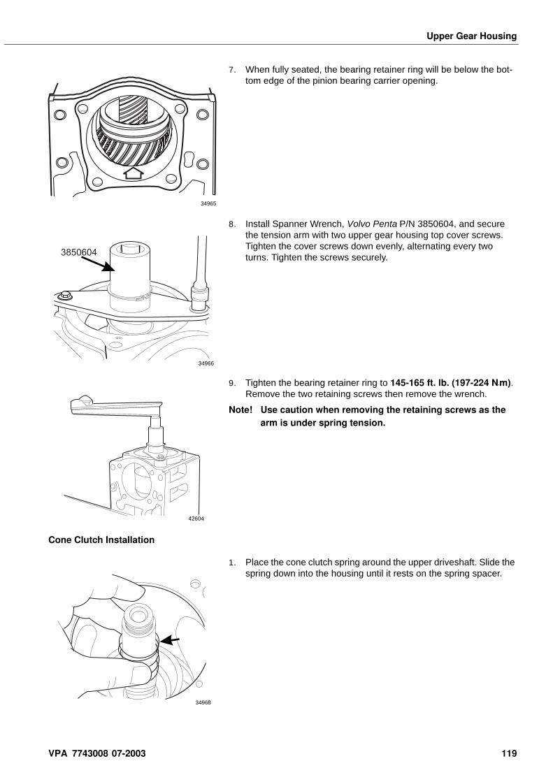
Upper Gear Housing
7. When fully seated, the bearing retainer ring will be below the bot-tom edge of the pinion bearing carrier opening.
8. Install Spanner Wrench, Volvo Penta P/N 3850604, and secure the tension arm with two upper gear housing top cover screws. Tighten the cover screws down evenly, alternating every two turns. Tighten the screws securely.
9. Tighten the bearing retainer ring to 145-165 ft. lb. (197-224 N•m). Remove the two retaining screws then remove the wrench.
Note! Use caution when removing the retaining screws as the arm is under spring tension.
Cone Clutch Installation
1. Place the cone clutch spring around the upper driveshaft. Slide the spring down into the housing until it rests on the spring spacer.
34965
3850604
34966
42604
34968
VPA 7743008 07-2003 119
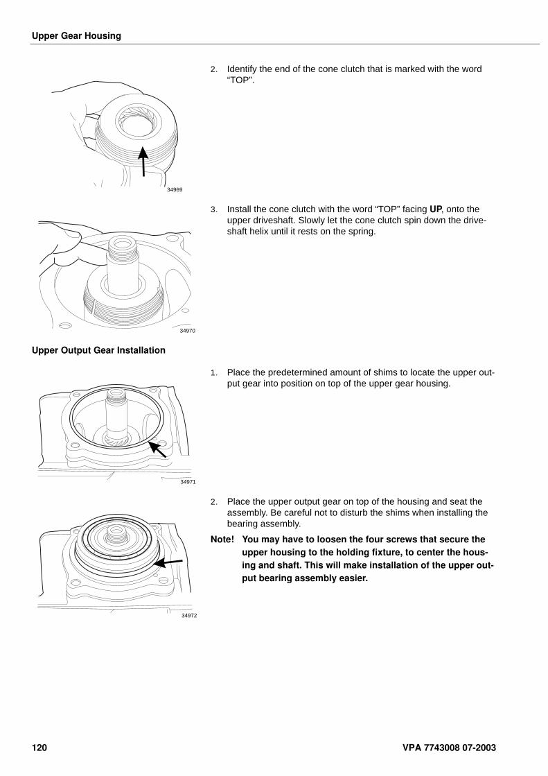
Upper Gear Housing
2. Identify the end of the cone clutch that is marked with the word “TOP”.
3. Install the cone clutch with the word “TOP” facing UP, onto the upper driveshaft. Slowly let the cone clutch spin down the drive-shaft helix until it rests on the spring.
Upper Output Gear Installation
1. Place the predetermined amount of shims to locate the upper out-put gear into position on top of the upper gear housing.
2. Place the upper output gear on top of the housing and seat the assembly. Be careful not to disturb the shims when installing the bearing assembly.
Note! You may have to loosen the four screws that secure the upper housing to the holding fixture, to center the hous-ing and shaft. This will make installation of the upper out-put bearing assembly easier.
34969
34970
34971
34972
120 VPA 7743008 07-2003
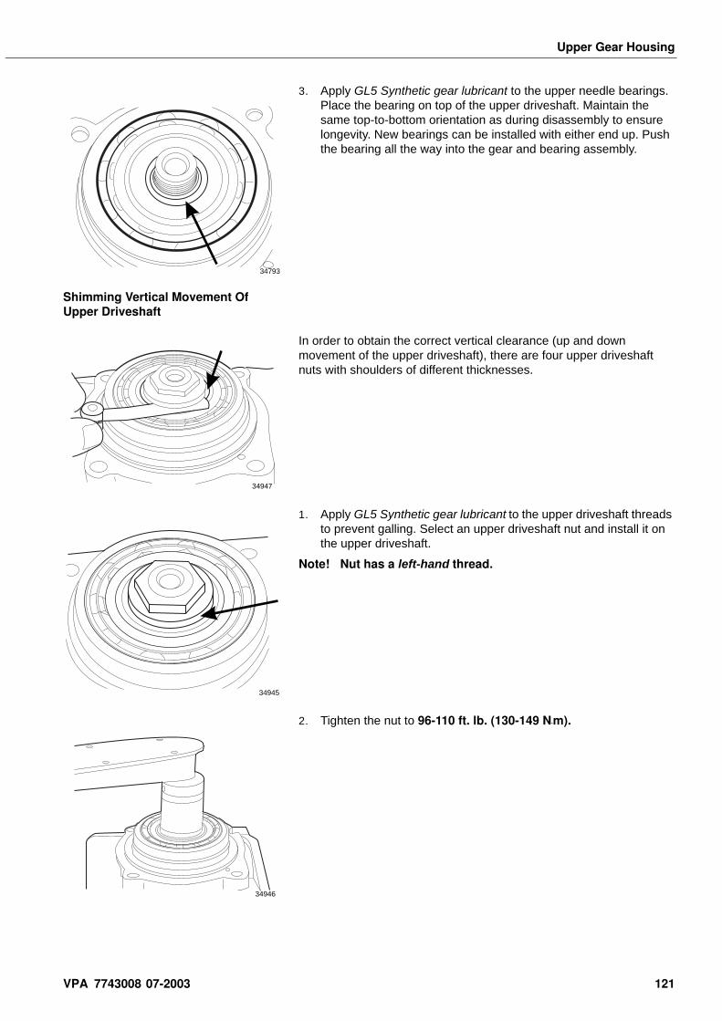
Upper Gear Housing
3. Apply GL5 Synthetic gear lubricant to the upper needle bearings. Place the bearing on top of the upper driveshaft. Maintain the same top-to-bottom orientation as during disassembly to ensure longevity. New bearings can be installed with either end up. Push the bearing all the way into the gear and bearing assembly.
Shimming Vertical Movement Of Upper Driveshaft
In order to obtain the correct vertical clearance (up and down movement of the upper driveshaft), there are four upper driveshaft nuts with shoulders of different thicknesses.
1. Apply GL5 Synthetic gear lubricant to the upper driveshaft threads to prevent galling. Select an upper driveshaft nut and install it on the upper driveshaft.
Note! Nut has a left-hand thread.
2. Tighten the nut to 96-110 ft. lb. (130-149 N•m).
34793
34947
34945
34946
VPA 7743008 07-2003 121
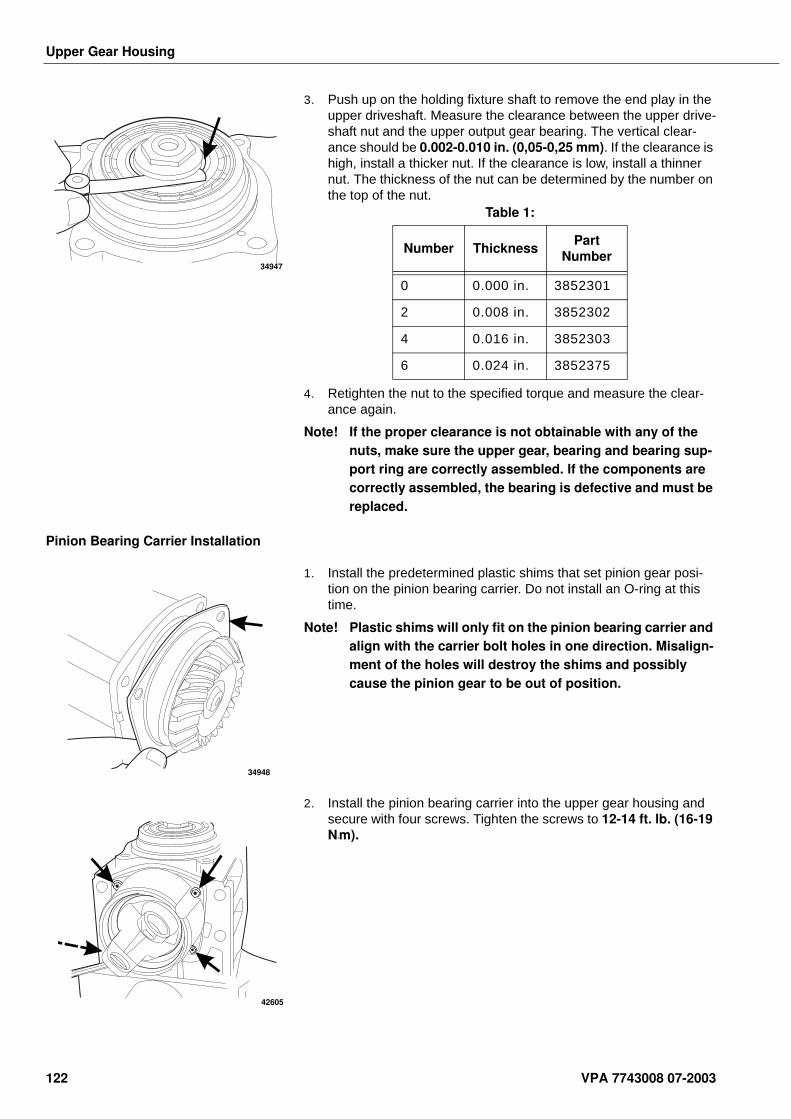
Upper Gear Housing
3. Push up on the holding fixture shaft to remove the end play in the upper driveshaft. Measure the clearance between the upper drive-shaft nut and the upper output gear bearing. The vertical clear-ance should be 0.002-0.010 in. (0,05-0,25 mm). If the clearance is high, install a thicker nut. If the clearance is low, install a thinner nut. The thickness of the nut can be determined by the number on the top of the nut.
4. Retighten the nut to the specified torque and measure the clear-ance again.
Note! If the proper clearance is not obtainable with any of the nuts, make sure the upper gear, bearing and bearing sup-port ring are correctly assembled. If the components are correctly assembled, the bearing is defective and must be replaced.
Pinion Bearing Carrier Installation
1. Install the predetermined plastic shims that set pinion gear posi-tion on the pinion bearing carrier. Do not install an O-ring at this time.
Note! Plastic shims will only fit on the pinion bearing carrier and align with the carrier bolt holes in one direction. Misalign-ment of the holes will destroy the shims and possibly cause the pinion gear to be out of position.
2. Install the pinion bearing carrier into the upper gear housing and secure with four screws. Tighten the screws to 12-14 ft. lb. (16-19 N•m).
34947
Table 1:
Number ThicknessPart
Number
0 0.000 in. 3852301
2 0.008 in. 3852302
4 0.016 in. 3852303
6 0.024 in. 3852375
34948
42605
122 VPA 7743008 07-2003
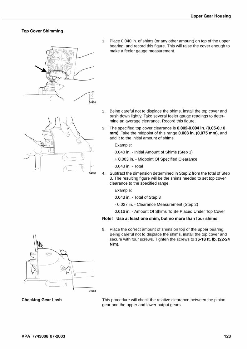
Upper Gear Housing
Top Cover Shimming
1. Place 0.040 in. of shims (or any other amount) on top of the upper bearing, and record this figure. This will raise the cover enough to make a feeler gauge measurement.
2. Being careful not to displace the shims, install the top cover and push down lightly. Take several feeler gauge readings to deter-mine an average clearance. Record this figure.
3. The specified top cover clearance is 0.002-0.004 in. (0,05-0,10 mm). Take the midpoint of this range 0.003 in. (0,075 mm), and add it to the initial amount of shims.
Example:
0.040 in. - Initial Amount of Shims (Step 1)
+ 0.003 in. - Midpoint Of Specified Clearance
0.043 in. - Total
4. Subtract the dimension determined in Step 2 from the total of Step 3. The resulting figure will be the shims needed to set top cover clearance to the specified range.
Example:
0.043 in. - Total of Step 3
- 0.027 in. - Clearance Measurement (Step 2)
0.016 in. - Amount Of Shims To Be Placed Under Top Cover
Note! Use at least one shim, but no more than four shims.
5. Place the correct amount of shims on top of the upper bearing. Being careful not to displace the shims, install the top cover and secure with four screws. Tighten the screws to 16-18 ft. lb. (22-24 N•m).
Checking Gear Lash This procedure will check the relative clearance between the pinion gear and the upper and lower output gears.
34950
34952
34953
VPA 7743008 07-2003 123
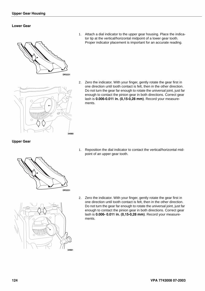
Upper Gear Housing
Lower Gear
1. Attach a dial indicator to the upper gear housing. Place the indica-tor tip at the vertical/horizontal midpoint of a lower gear tooth. Proper indicator placement is important for an accurate reading.
2. Zero the indicator. With your finger, gently rotate the gear first in one direction until tooth contact is felt, then in the other direction. Do not turn the gear far enough to rotate the universal joint, just far enough to contact the pinion gear in both directions. Correct gear lash is 0.006-0.011 in. (0,15-0,28 mm). Record your measure-ments.
Upper Gear
1. Reposition the dial indicator to contact the vertical/horizontal mid-point of an upper gear tooth.
2. Zero the indicator. With your finger, gently rotate the gear first in one direction until tooth contact is felt, then in the other direction. Do not turn the gear far enough to rotate the universal joint, just far enough to contact the pinion gear in both directions. Correct gear lash is 0.006- 0.011 in. (0,15-0,28 mm). Record your measure-ments.
DR3231
34980
DR3231
34981
124 VPA 7743008 07-2003
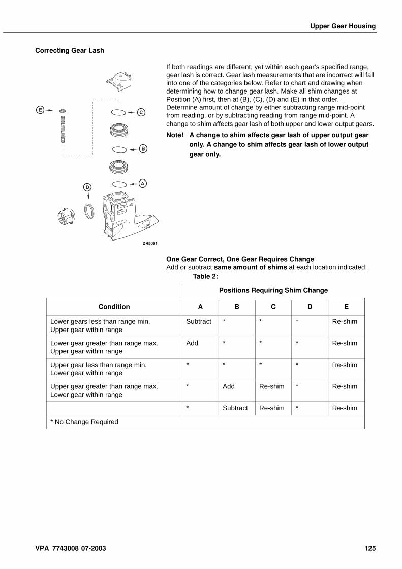
Upper Gear Housing
Correcting Gear Lash
If both readings are different, yet within each gear’s specified range, gear lash is correct. Gear lash measurements that are incorrect will fall into one of the categories below. Refer to chart and drawing when determining how to change gear lash. Make all shim changes at Position (A) first, then at (B), (C), (D) and (E) in that order. Determine amount of change by either subtracting range mid-point from reading, or by subtracting reading from range mid-point. A change to shim affects gear lash of both upper and lower output gears.
Note! A change to shim affects gear lash of upper output gear only. A change to shim affects gear lash of lower output gear only.
One Gear Correct, One Gear Requires ChangeAdd or subtract same amount of shims at each location indicated.
EC
B
AD
DR5061
Table 2:
Positions Requiring Shim Change
Condition A B C D E
Lower gears less than range min. Upper gear within range
Subtract * * * Re-shim
Lower gear greater than range max. Upper gear within range
Add * * * Re-shim
Upper gear less than range min. Lower gear within range
* * * * Re-shim
Upper gear greater than range max. Lower gear within range
* Add Re-shim * Re-shim
* Subtract Re-shim * Re-shim
* No Change Required
VPA 7743008 07-2003 125
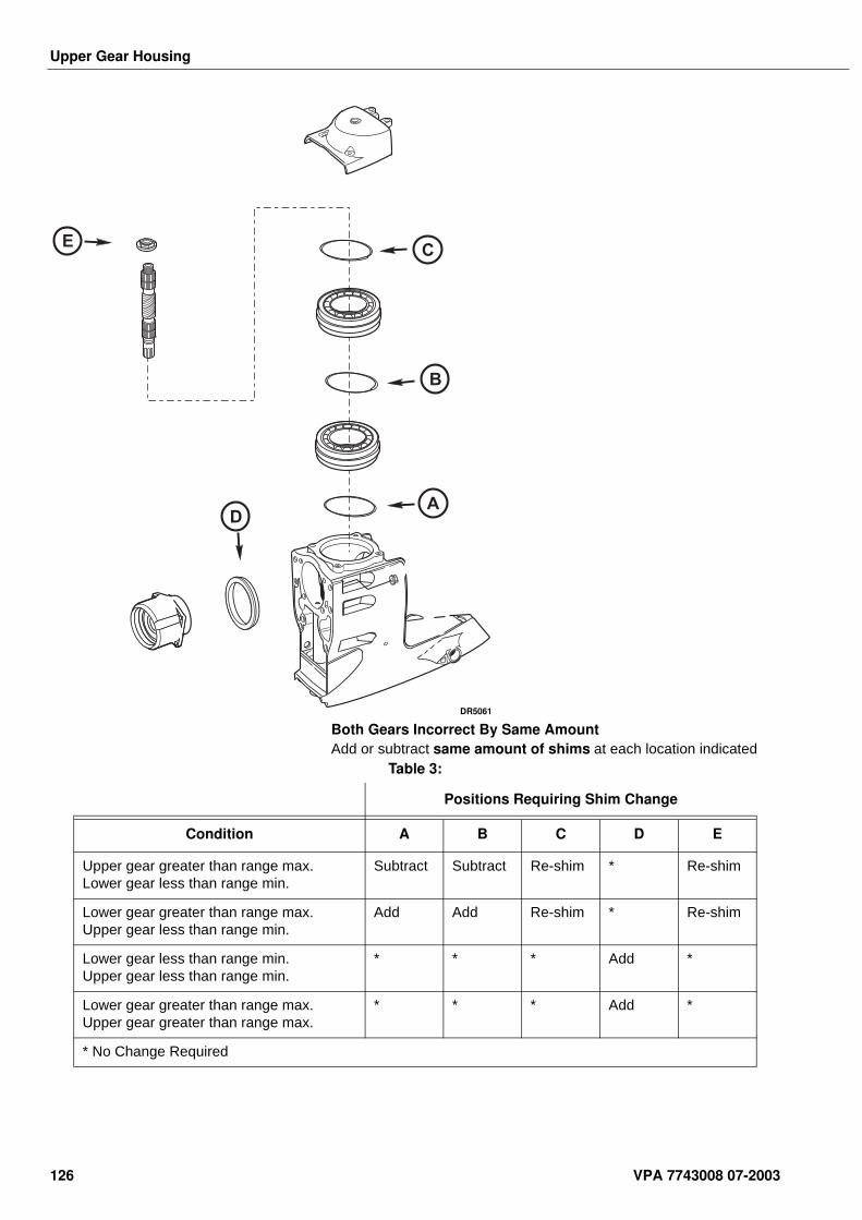
Upper Gear Housing
Both Gears Incorrect By Same AmountAdd or subtract same amount of shims at each location indicated
EC
B
AD
DR5061
Table 3:
Positions Requiring Shim Change
Condition A B C D E
Upper gear greater than range max. Lower gear less than range min.
Subtract Subtract Re-shim * Re-shim
Lower gear greater than range max. Upper gear less than range min.
Add Add Re-shim * Re-shim
Lower gear less than range min. Upper gear less than range min.
* * * Add *
Lower gear greater than range max. Upper gear greater than range max.
* * * Add *
* No Change Required
126 VPA 7743008 07-2003
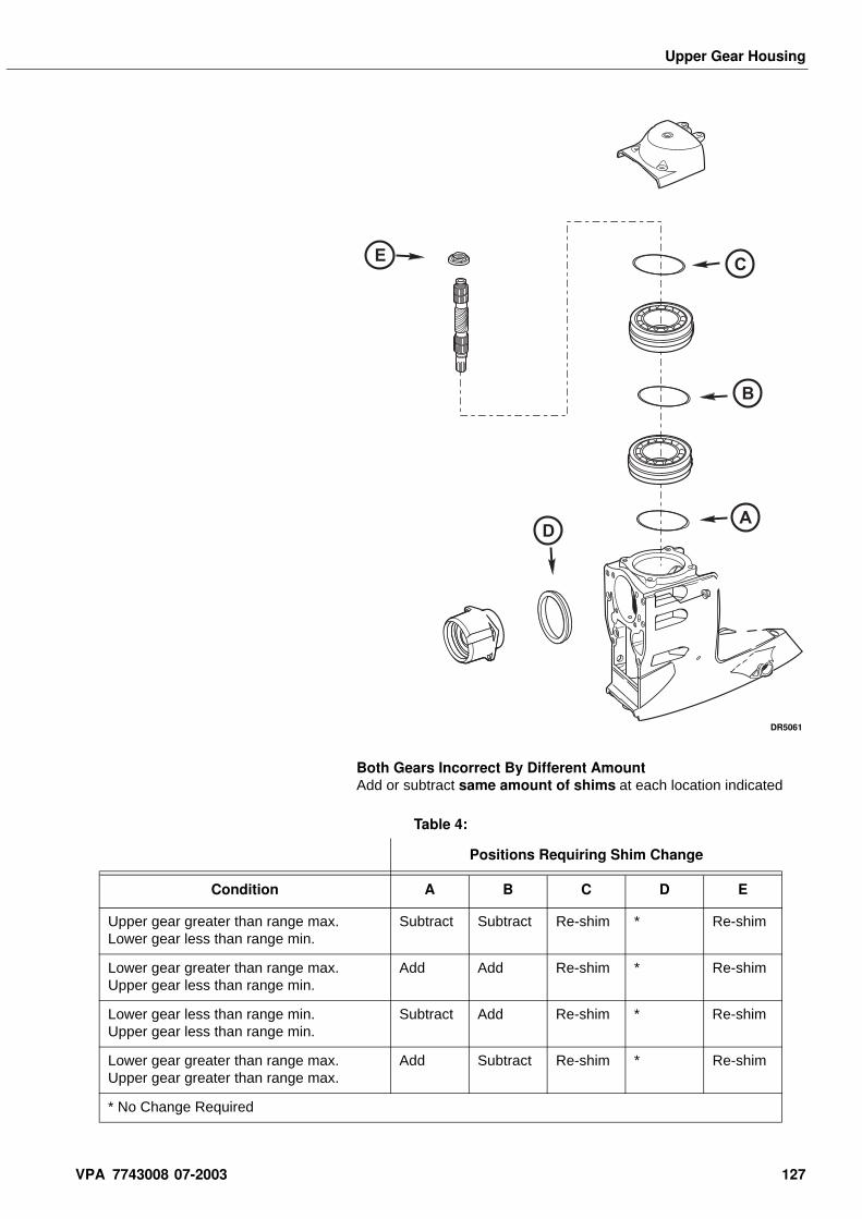
Upper Gear Housing
Both Gears Incorrect By Different AmountAdd or subtract same amount of shims at each location indicated
EC
B
AD
DR5061
Table 4:
Positions Requiring Shim Change
Condition A B C D E
Upper gear greater than range max. Lower gear less than range min.
Subtract Subtract Re-shim * Re-shim
Lower gear greater than range max. Upper gear less than range min.
Add Add Re-shim * Re-shim
Lower gear less than range min. Upper gear less than range min.
Subtract Add Re-shim * Re-shim
Lower gear greater than range max. Upper gear greater than range max.
Add Subtract Re-shim * Re-shim
* No Change Required
VPA 7743008 07-2003 127
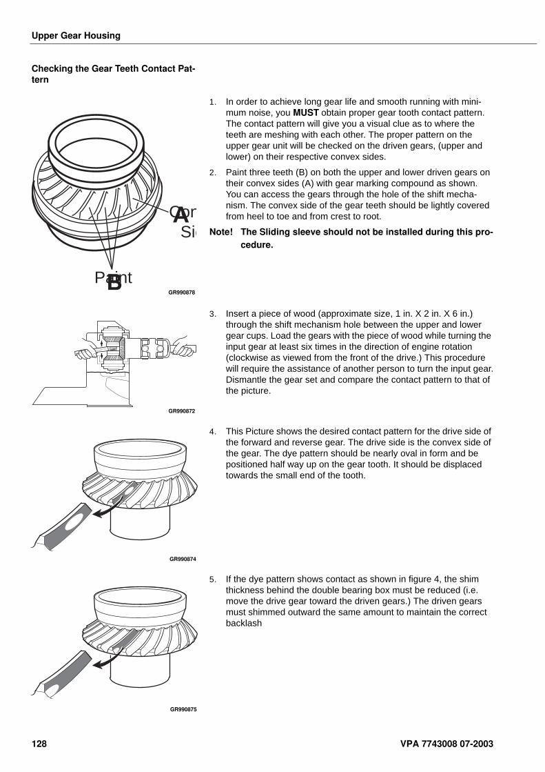
Upper Gear Housing
Checking the Gear Teeth Contact Pat-tern
1. In order to achieve long gear life and smooth running with mini-mum noise, you MUST obtain proper gear tooth contact pattern. The contact pattern will give you a visual clue as to where the teeth are meshing with each other. The proper pattern on the upper gear unit will be checked on the driven gears, (upper and lower) on their respective convex sides.
2. Paint three teeth (B) on both the upper and lower driven gears on their convex sides (A) with gear marking compound as shown. You can access the gears through the hole of the shift mecha-nism. The convex side of the gear teeth should be lightly covered from heel to toe and from crest to root.
Note! The Sliding sleeve should not be installed during this pro-cedure.
3. Insert a piece of wood (approximate size, 1 in. X 2 in. X 6 in.) through the shift mechanism hole between the upper and lower gear cups. Load the gears with the piece of wood while turning the input gear at least six times in the direction of engine rotation (clockwise as viewed from the front of the drive.) This procedure will require the assistance of another person to turn the input gear.Dismantle the gear set and compare the contact pattern to that of the picture.
4. This Picture shows the desired contact pattern for the drive side of the forward and reverse gear. The drive side is the convex side of the gear. The dye pattern should be nearly oval in form and be positioned half way up on the gear tooth. It should be displaced towards the small end of the tooth.
5. If the dye pattern shows contact as shown in figure 4, the shim thickness behind the double bearing box must be reduced (i.e. move the drive gear toward the driven gears.) The driven gears must shimmed outward the same amount to maintain the correct backlash
Paint
ConSid
A
BGR990878
GR990872
GR990874
GR990875
128 VPA 7743008 07-2003
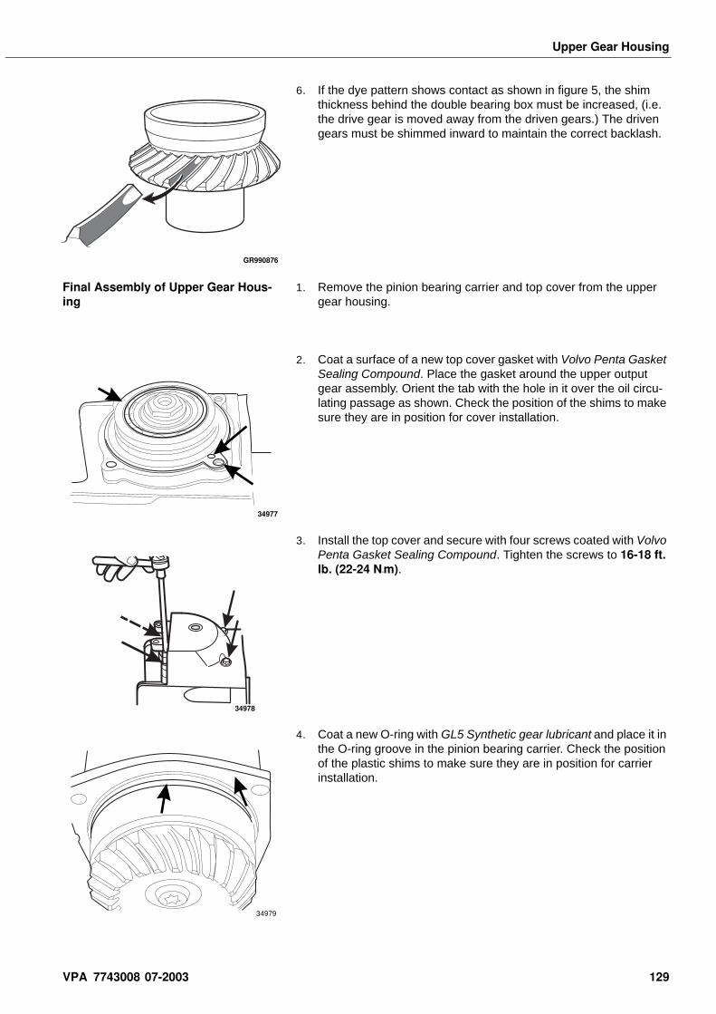
Upper Gear Housing
6. If the dye pattern shows contact as shown in figure 5, the shim thickness behind the double bearing box must be increased, (i.e. the drive gear is moved away from the driven gears.) The driven gears must be shimmed inward to maintain the correct backlash.
Final Assembly of Upper Gear Hous-ing
1. Remove the pinion bearing carrier and top cover from the upper gear housing.
2. Coat a surface of a new top cover gasket with Volvo Penta Gasket Sealing Compound. Place the gasket around the upper output gear assembly. Orient the tab with the hole in it over the oil circu-lating passage as shown. Check the position of the shims to make sure they are in position for cover installation.
3. Install the top cover and secure with four screws coated with Volvo Penta Gasket Sealing Compound. Tighten the screws to 16-18 ft. lb. (22-24 N•m).
4. Coat a new O-ring with GL5 Synthetic gear lubricant and place it in the O-ring groove in the pinion bearing carrier. Check the position of the plastic shims to make sure they are in position for carrier installation.
GR990876
34977
34978
34979
VPA 7743008 07-2003 129
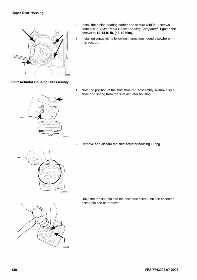
Upper Gear Housing
5. Install the pinion bearing carrier and secure with four screws coated with Volvo Penta Gasket Sealing Compound. Tighten the screws to 12-14 ft. lb. (16-19 N•m).
6. Install universal joints following instructions found elsewhere in this section.
Shift Actuator Housing Disassembly
1. Note the position of the shift shoe for reassembly. Remove shift shoe and spring from the shift actuator housing.
2. Remove and discard the shift actuator housing O-ring.
3. Drive the tension pin into the eccentric piston until the eccentric piston pin can be removed.
42606
34982
34983
J
K34984
130 VPA 7743008 07-2003
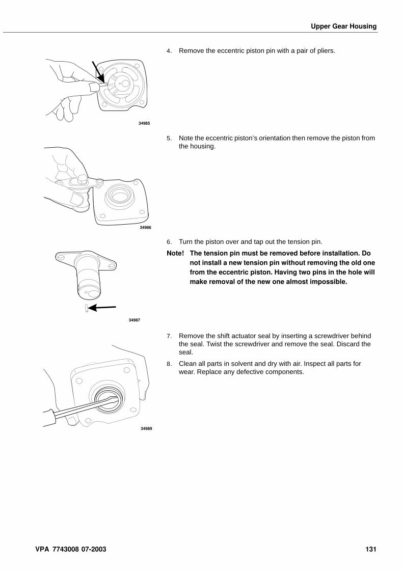
Upper Gear Housing
4. Remove the eccentric piston pin with a pair of pliers.
5. Note the eccentric piston’s orientation then remove the piston from the housing.
6. Turn the piston over and tap out the tension pin.
Note! The tension pin must be removed before installation. Do not install a new tension pin without removing the old one from the eccentric piston. Having two pins in the hole will make removal of the new one almost impossible.
7. Remove the shift actuator seal by inserting a screwdriver behind the seal. Twist the screwdriver and remove the seal. Discard the seal.
8. Clean all parts in solvent and dry with air. Inspect all parts for wear. Replace any defective components.
34985
34986
34987
34989
VPA 7743008 07-2003 131
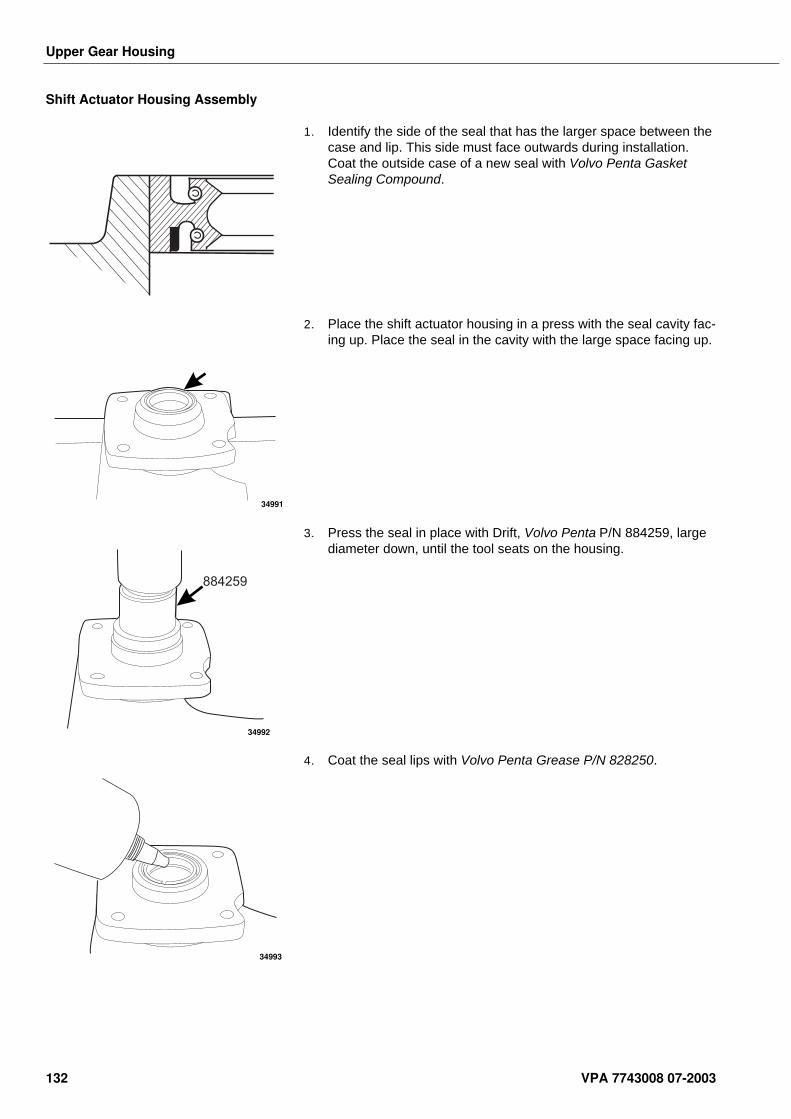
Upper Gear Housing
Shift Actuator Housing Assembly
1. Identify the side of the seal that has the larger space between the case and lip. This side must face outwards during installation. Coat the outside case of a new seal with Volvo Penta Gasket Sealing Compound.
2. Place the shift actuator housing in a press with the seal cavity fac-ing up. Place the seal in the cavity with the large space facing up.
3. Press the seal in place with Drift, Volvo Penta P/N 884259, large diameter down, until the tool seats on the housing.
4. Coat the seal lips with Volvo Penta Grease P/N 828250.
34991
884259
34992
34993
132 VPA 7743008 07-2003
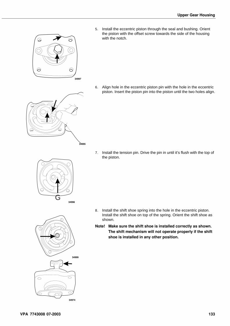
Upper Gear Housing
5. Install the eccentric piston through the seal and bushing. Orient the piston with the offset screw towards the side of the housing with the notch.
6. Align hole in the eccentric piston pin with the hole in the eccentric piston. Insert the piston pin into the piston until the two holes align.
7. Install the tension pin. Drive the pin in until it’s flush with the top of the piston.
8. Install the shift shoe spring into the hole in the eccentric piston. Install the shift shoe on top of the spring. Orient the shift shoe as shown.
Note! Make sure the shift shoe is installed correctly as shown. The shift mechanism will not operate properly if the shift shoe is installed in any other position.
34997
34995
G34996
34999
34974
VPA 7743008 07-2003 133
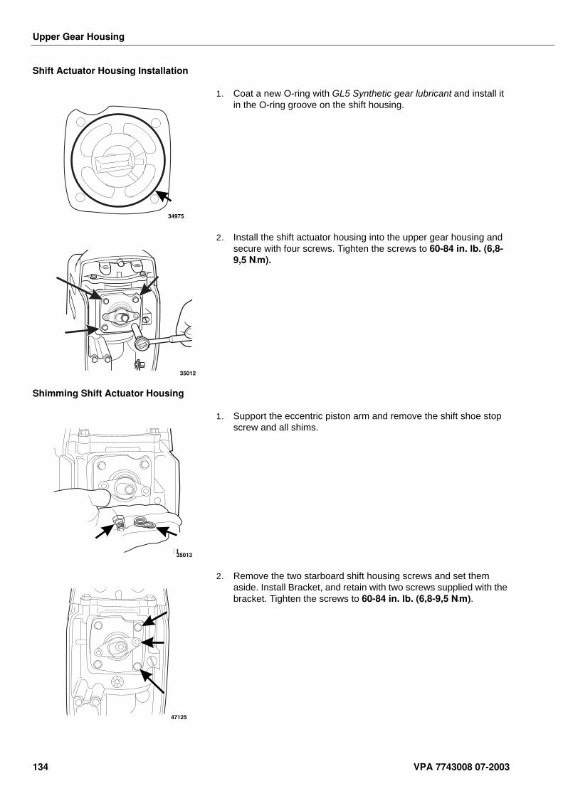
Upper Gear Housing
Shift Actuator Housing Installation
1. Coat a new O-ring with GL5 Synthetic gear lubricant and install it in the O-ring groove on the shift housing.
2. Install the shift actuator housing into the upper gear housing and secure with four screws. Tighten the screws to 60-84 in. lb. (6,8-9,5 N•m).
Shimming Shift Actuator Housing
1. Support the eccentric piston arm and remove the shift shoe stop screw and all shims.
2. Remove the two starboard shift housing screws and set them aside. Install Bracket, and retain with two screws supplied with the bracket. Tighten the screws to 60-84 in. lb. (6,8-9,5 N•m).
34975
35012
35013
47125
134 VPA 7743008 07-2003
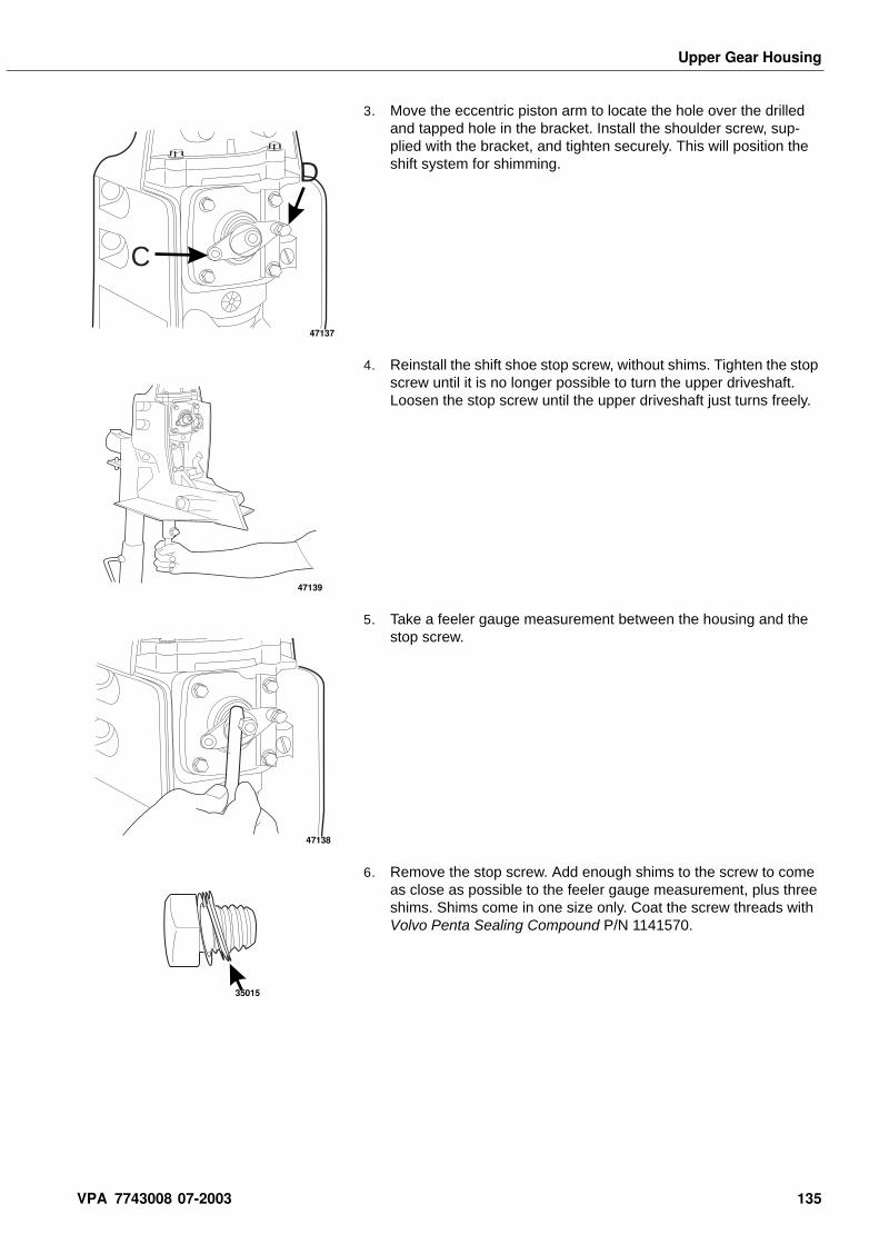
Upper Gear Housing
3. Move the eccentric piston arm to locate the hole over the drilled and tapped hole in the bracket. Install the shoulder screw, sup-plied with the bracket, and tighten securely. This will position the shift system for shimming.
4. Reinstall the shift shoe stop screw, without shims. Tighten the stop screw until it is no longer possible to turn the upper driveshaft. Loosen the stop screw until the upper driveshaft just turns freely.
5. Take a feeler gauge measurement between the housing and the stop screw.
6. Remove the stop screw. Add enough shims to the screw to come as close as possible to the feeler gauge measurement, plus three shims. Shims come in one size only. Coat the screw threads with Volvo Penta Sealing Compound P/N 1141570.
D
C
47137
47139
47138
35015
VPA 7743008 07-2003 135
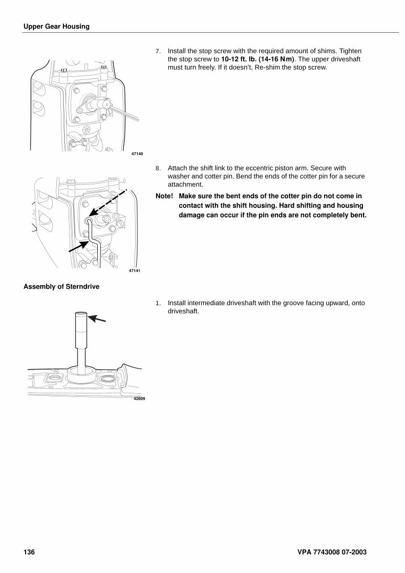
Upper Gear Housing
7. Install the stop screw with the required amount of shims. Tighten the stop screw to 10-12 ft. lb. (14-16 N•m). The upper driveshaft must turn freely. If it doesn’t, Re-shim the stop screw.
8. Attach the shift link to the eccentric piston arm. Secure with washer and cotter pin. Bend the ends of the cotter pin for a secure attachment.
Note! Make sure the bent ends of the cotter pin do not come in contact with the shift housing. Hard shifting and housing damage can occur if the pin ends are not completely bent.
Assembly of Sterndrive
1. Install intermediate driveshaft with the groove facing upward, onto driveshaft.
47140
47141
42609
136 VPA 7743008 07-2003
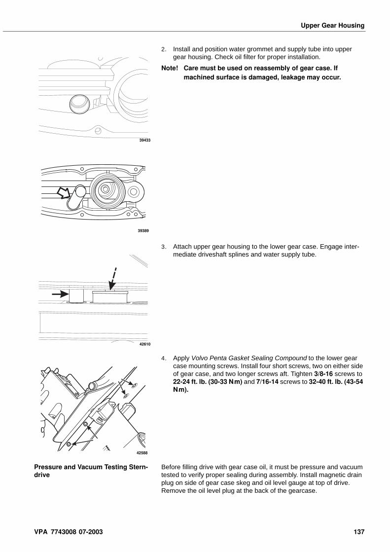
Upper Gear Housing
2. Install and position water grommet and supply tube into upper gear housing. Check oil filter for proper installation.
Note! Care must be used on reassembly of gear case. If machined surface is damaged, leakage may occur.
3. Attach upper gear housing to the lower gear case. Engage inter-mediate driveshaft splines and water supply tube.
4. Apply Volvo Penta Gasket Sealing Compound to the lower gear case mounting screws. Install four short screws, two on either side of gear case, and two longer screws aft. Tighten 3/8-16 screws to 22-24 ft. lb. (30-33 N•m) and 7/16-14 screws to 32-40 ft. lb. (43-54 N•m).
Pressure and Vacuum Testing Stern-drive
Before filling drive with gear case oil, it must be pressure and vacuum tested to verify proper sealing during assembly. Install magnetic drain plug on side of gear case skeg and oil level gauge at top of drive. Remove the oil level plug at the back of the gearcase.
39433
39389
42610
42588
VPA 7743008 07-2003 137
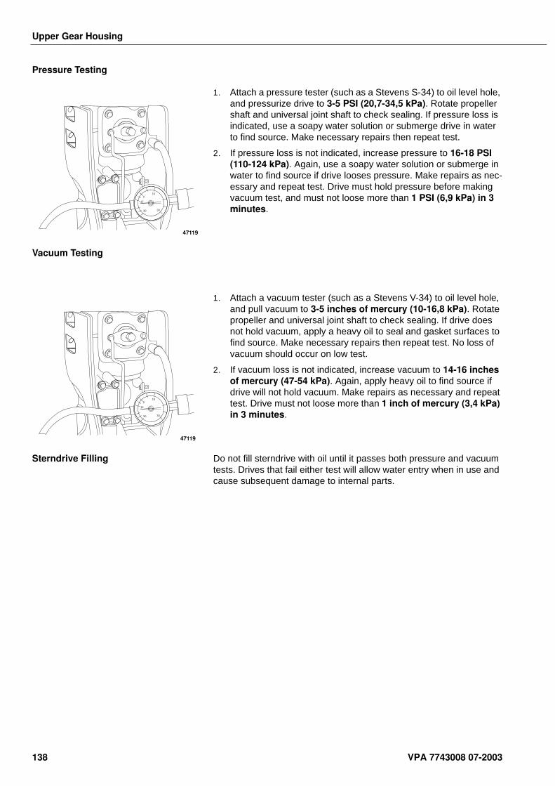
Upper Gear Housing
Pressure Testing
1. Attach a pressure tester (such as a Stevens S-34) to oil level hole, and pressurize drive to 3-5 PSI (20,7-34,5 kPa). Rotate propeller shaft and universal joint shaft to check sealing. If pressure loss is indicated, use a soapy water solution or submerge drive in water to find source. Make necessary repairs then repeat test.
2. If pressure loss is not indicated, increase pressure to 16-18 PSI (110-124 kPa). Again, use a soapy water solution or submerge in water to find source if drive looses pressure. Make repairs as nec-essary and repeat test. Drive must hold pressure before making vacuum test, and must not loose more than 1 PSI (6,9 kPa) in 3 minutes.
Vacuum Testing
1. Attach a vacuum tester (such as a Stevens V-34) to oil level hole, and pull vacuum to 3-5 inches of mercury (10-16,8 kPa). Rotate propeller and universal joint shaft to check sealing. If drive does not hold vacuum, apply a heavy oil to seal and gasket surfaces to find source. Make necessary repairs then repeat test. No loss of vacuum should occur on low test.
2. If vacuum loss is not indicated, increase vacuum to 14-16 inches of mercury (47-54 kPa). Again, apply heavy oil to find source if drive will not hold vacuum. Make repairs as necessary and repeat test. Drive must not loose more than 1 inch of mercury (3,4 kPa) in 3 minutes.
Sterndrive Filling Do not fill sterndrive with oil until it passes both pressure and vacuum tests. Drives that fail either test will allow water entry when in use and cause subsequent damage to internal parts.
15
15
30 30
0
47119
15
15
30 30
0
47119
138 VPA 7743008 07-2003
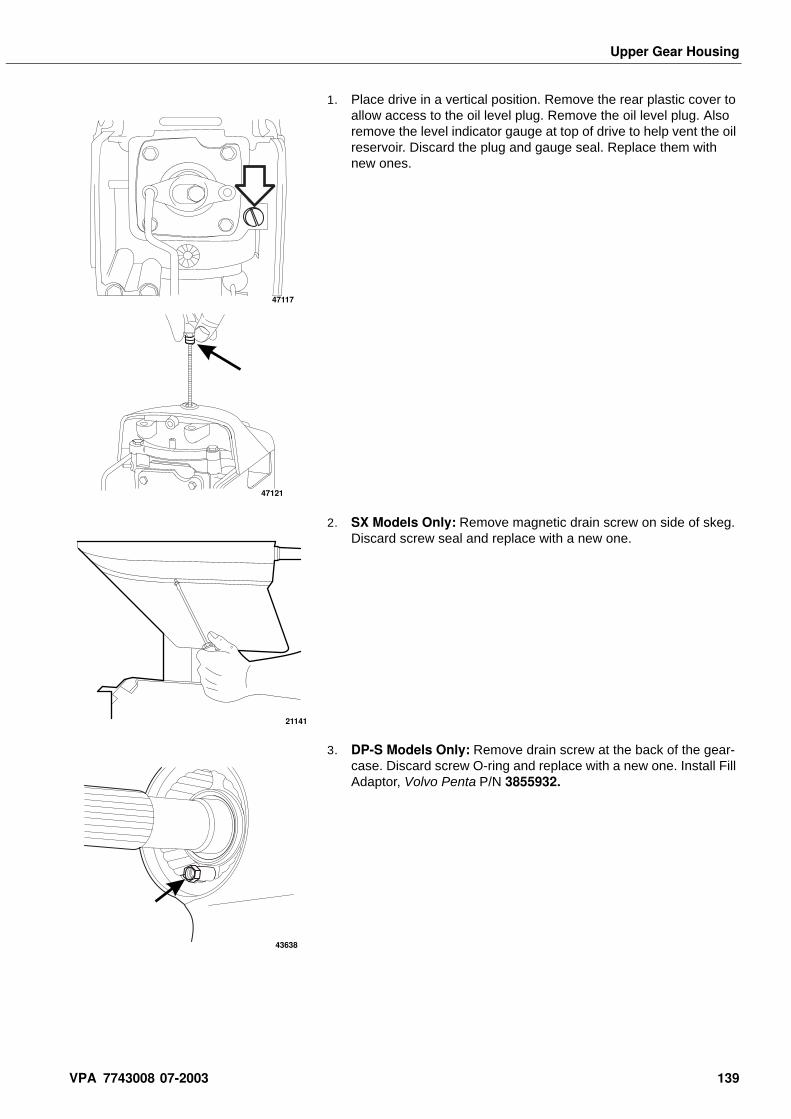
Upper Gear Housing
1. Place drive in a vertical position. Remove the rear plastic cover to allow access to the oil level plug. Remove the oil level plug. Also remove the level indicator gauge at top of drive to help vent the oil reservoir. Discard the plug and gauge seal. Replace them with new ones.
2. SX Models Only: Remove magnetic drain screw on side of skeg. Discard screw seal and replace with a new one.
3. DP-S Models Only: Remove drain screw at the back of the gear-case. Discard screw O-ring and replace with a new one. Install Fill Adaptor, Volvo Penta P/N 3855932.
47117
47121
21141
43638
VPA 7743008 07-2003 139
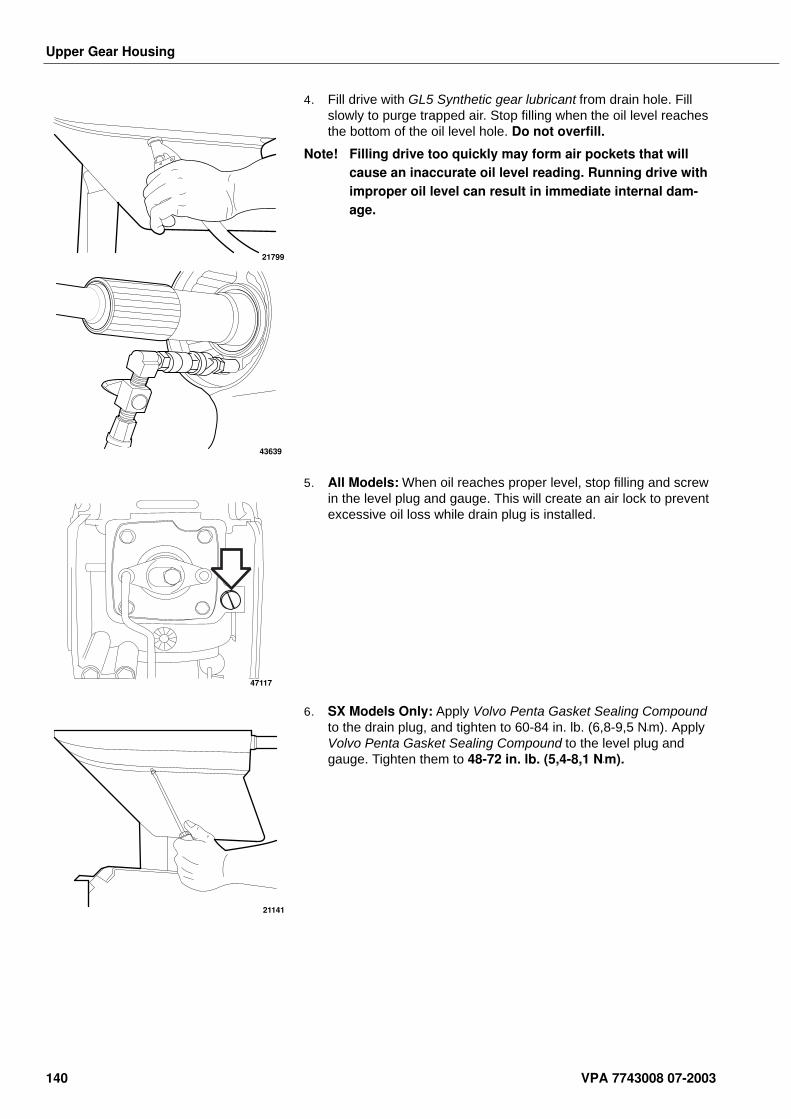
Upper Gear Housing
4. Fill drive with GL5 Synthetic gear lubricant from drain hole. Fill slowly to purge trapped air. Stop filling when the oil level reaches the bottom of the oil level hole. Do not overfill.
Note! Filling drive too quickly may form air pockets that will cause an inaccurate oil level reading. Running drive with improper oil level can result in immediate internal dam-age.
5. All Models: When oil reaches proper level, stop filling and screw in the level plug and gauge. This will create an air lock to prevent excessive oil loss while drain plug is installed.
6. SX Models Only: Apply Volvo Penta Gasket Sealing Compound to the drain plug, and tighten to 60-84 in. lb. (6,8-9,5 N•m). Apply Volvo Penta Gasket Sealing Compound to the level plug and gauge. Tighten them to 48-72 in. lb. (5,4-8,1 N•m).
21799
43639
47117
21141
140 VPA 7743008 07-2003
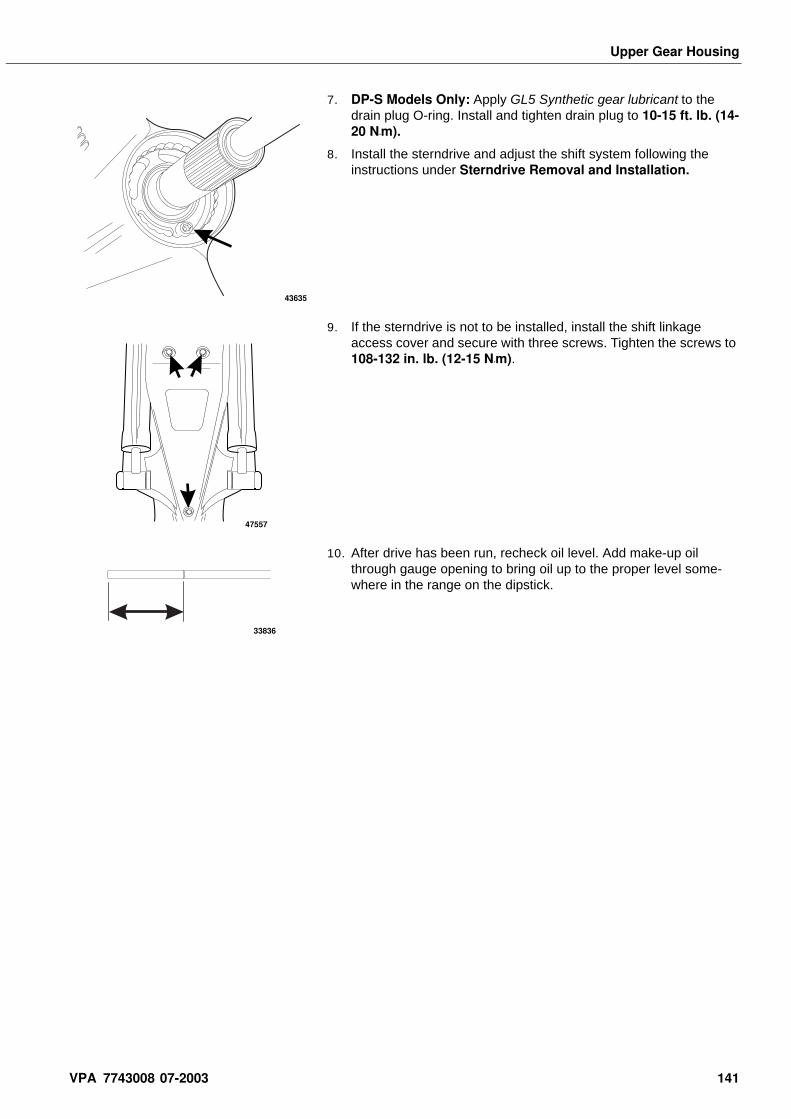
Upper Gear Housing
7. DP-S Models Only: Apply GL5 Synthetic gear lubricant to the drain plug O-ring. Install and tighten drain plug to 10-15 ft. lb. (14-20 N•m).
8. Install the sterndrive and adjust the shift system following the instructions under Sterndrive Removal and Installation.
9. If the sterndrive is not to be installed, install the shift linkage access cover and secure with three screws. Tighten the screws to 108-132 in. lb. (12-15 N•m).
10. After drive has been run, recheck oil level. Add make-up oil through gauge opening to bring oil up to the proper level some-where in the range on the dipstick.
43635
47557
33836
VPA 7743008 07-2003 141
Upper Gear Housing
SpecificationsDescription U.S. Metric
Bearing retainer ring 145-165 ft. lb. 197-224 N•m
Nut
Upper driveshaft 96-110 ft. lb. 130-149 N•m
Screw
Drain - Single Proper 60-84 in. lb. 6,8-9,5 N•m
Drain - Dual Prop 10-15 ft. lb. 14-20 N•m
Lower to upper gear housing
3/8-16 22-24 ft. lb. 30-33 N•m
7/16-14 32-40 ft. lb. 43-54 N•m
Oil level gauge and plug 48-72 in. lb. 5,4-8,1 N•m
Pinion bearing carrier 12-14 ft. lb. 16-19 N•m
Shift actuator housing 60-84 in. lb. 6,8-9,5 N•m
Shift linkage access cover 108-132 in. lb. 12-15 N•m
Shift shoe stop screw 10-12 ft. lb. 14-16 N•m
Top cover 16-18 ft. lb. 22-24 N•m
Water passage cover 60-84 in. lb. 6,8-9,5 N•m
142 VPA 7743008 07-2003
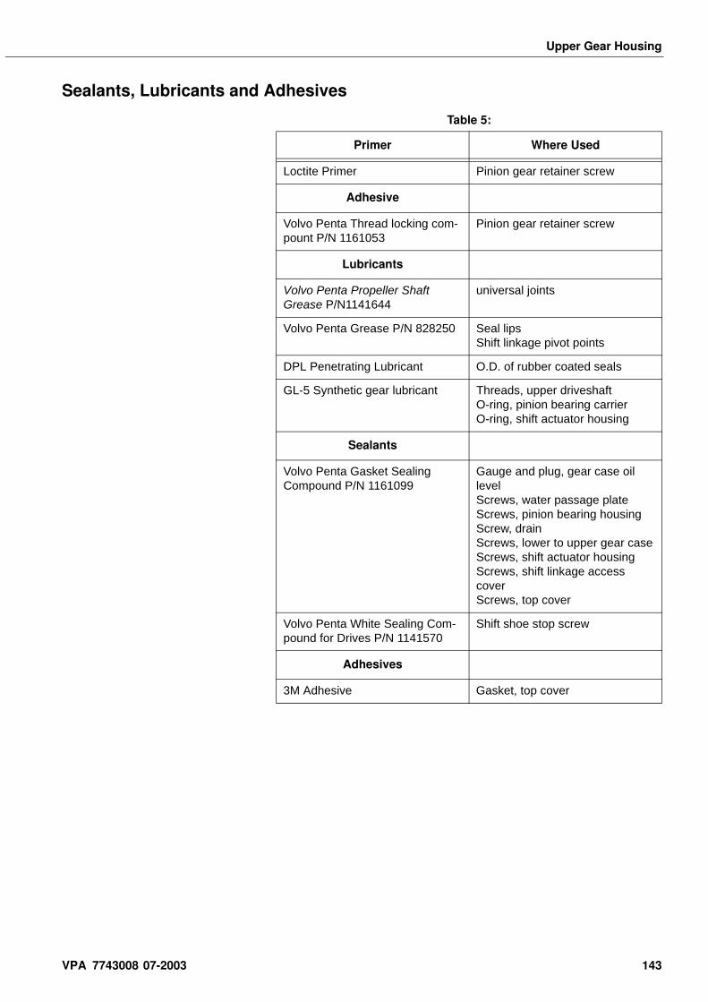
Upper Gear Housing
Sealants, Lubricants and Adhesives
Table 5:
Primer Where Used
Loctite Primer Pinion gear retainer screw
Adhesive
Volvo Penta Thread locking com-pount P/N 1161053
Pinion gear retainer screw
Lubricants
Volvo Penta Propeller Shaft Grease P/N1141644
universal joints
Volvo Penta Grease P/N 828250 Seal lipsShift linkage pivot points
DPL Penetrating Lubricant O.D. of rubber coated seals
GL-5 Synthetic gear lubricant Threads, upper driveshaftO-ring, pinion bearing carrierO-ring, shift actuator housing
Sealants
Volvo Penta Gasket Sealing Compound P/N 1161099
Gauge and plug, gear case oil levelScrews, water passage plateScrews, pinion bearing housingScrew, drainScrews, lower to upper gear caseScrews, shift actuator housingScrews, shift linkage access coverScrews, top cover
Volvo Penta White Sealing Com-pound for Drives P/N 1141570
Shift shoe stop screw
Adhesives
3M Adhesive Gasket, top cover
VPA 7743008 07-2003 143
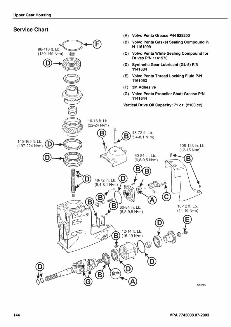
Upper Gear Housing
Service Chart
D
E
D
D DD
D
D
B
BB
B
B
B
B
B
B
C
A
A
G
F
B
96-110 ft. Lb.(130-149 N•m)
145-165 ft. Lb.(197-224 N•m)
16-18 ft. Lb.(22-24 N•m)
48-72 ft. Lb.5,4-8,1 N•m)
D D48-72 in. Lb.(5,4-8,1 N•m)
108-123 in. Lb.(12-15 N•m)
60-84 in. Lb.(6,8-9,5 N•m)
10-12 ft. Lb.(14-16 N•m)
12-14 ft. Lb.(16-19 N•m)
60-84 in. Lb.(6,8-9,5 N•m)
(A) Volvo Penta Grease P/N 828250
(B) Volvo Penta Gasket Sealing Compound P/N 1161099
(C) Volvo Penta White Sealing Compound for Drives P/N 1141570
(D) Synthetic Gear Lubricant (GL-5) P/N 1141634
(E) Volvo Penta Thread Locking Fluid P/N 1161053
(F) 3M Adhesive
(G) Volvo Penta Propeller Shaft Grease P/N 1141644
Vertical Drive Oil Capacity: 71 oz. (2100 cc)
DR5023
144 VPA 7743008 07-2003
SX Lower Gearcase
SX Lower GearcaseTable of Contents Special Tools . . . . . . . . . . . . . . . . . . . . . . . . . . . . . . . . . . . . . 152
Lower Gearcase Removal . . . . . . . . . . . . . . . . . . . . . . . . . . 153Lower Gearcase Disassembly . . . . . . . . . . . . . . . . . 154
Propshaft Bearing Housing Service . . . . . . . . . . . . . . . . . . 154Seal and Bearing Removal . . . . . . . . . . . . . . . . . . . . . . . . . . 155Seal and Bearing Installation . . . . . . . . . . . . . . . . . . . . . . . . 155Propshaft Bearing Removal . . . . . . . . . . . . . . . . . . . . . . . . . 156Propshaft Bearing Installation . . . . . . . . . . . . . . . . . . . . . . . 157Intermediate Driveshaft and Water Tube Guide Removal . 157Driveshaft and Gear Removal . . . . . . . . . . . . . . . . . . . . . . . 158Pinion Bearing Removal . . . . . . . . . . . . . . . . . . . . . . . . . . . 161Driveshaft Bearing Removal and Installation . . . . . . . . . . 161Pinion Shimming . . . . . . . . . . . . . . . . . . . . . . . . . . . . . . . . . 162
Lower Gearease Assembly . . . . . . . . . . . . . . . . . . . 164Propshaft Gear - Bearing Installation . . . . . . . . . . . . . . . . . 164Propshaft Gear Shimming . . . . . . . . . . . . . . . . . . . . . . . . . . 165Propshaft Gear - Bearing Cup Installation . . . . . . . . . . . . . 166Pinion Bearing Installation . . . . . . . . . . . . . . . . . . . . . . . . . 167Driveshaft and Gear Installation . . . . . . . . . . . . . . . . . . . . . 168Setting Initial Rolling Torque . . . . . . . . . . . . . . . . . . . . . . . . 169Initial Propshaft Bearing Housing Shimming . . . . . . . . . . 170Setting Final Rolling Torque . . . . . . . . . . . . . . . . . . . . . . . . 171Gear Lash Checking . . . . . . . . . . . . . . . . . . . . . . . . . . . . . . . 171Checking Gear Contact - SX Lower Unit . . . . . . . . . . . . . . 172Final Propshaft Bearing Housing Shimming . . . . . . . . . . . 174Propshaft Bearing Housing - Retainer Installation . . . . . . 175Lower Gearcase Installation . . . . . . . . . . . . . . . . . . . . . . . . 176Pressure and Vacuum Testing Sterndrive . . . . . . . . . . . . . 178Sterndrive Filling . . . . . . . . . . . . . . . . . . . . . . . . . . . . . . . . . 179
Specifications . . . . . . . . . . . . . . . . . . . . . . . . . . . . . . 181Sealants, Lubricants and Adhesives . . . . . . . . . . . 182Service Chart . . . . . . . . . . . . . . . . . . . . . . . . . . . . . . 183
Safety Warnings Before beginning work in this section, read Safety chapter at end of this manual.
Several of the following procedures require the use of an arbor or hydraulic press. Always wear safety glasses when using this device to perform these procedures.
VPA 7743008 07-2003 145
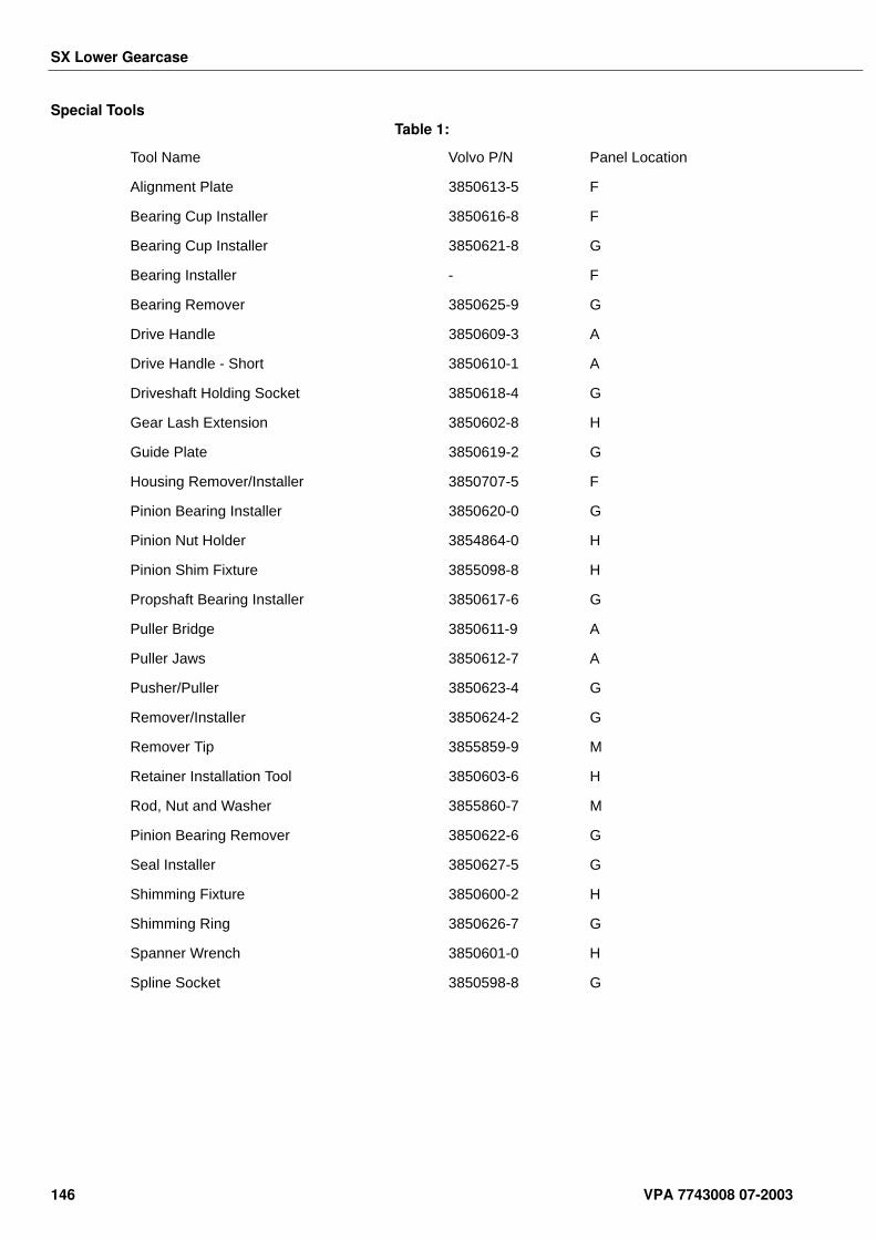
SX Lower Gearcase
Special ToolsTable 1:
Tool Name Volvo P/N Panel Location
Alignment Plate 3850613-5 F
Bearing Cup Installer 3850616-8 F
Bearing Cup Installer 3850621-8 G
Bearing Installer - F
Bearing Remover 3850625-9 G
Drive Handle 3850609-3 A
Drive Handle - Short 3850610-1 A
Driveshaft Holding Socket 3850618-4 G
Gear Lash Extension 3850602-8 H
Guide Plate 3850619-2 G
Housing Remover/Installer 3850707-5 F
Pinion Bearing Installer 3850620-0 G
Pinion Nut Holder 3854864-0 H
Pinion Shim Fixture 3855098-8 H
Propshaft Bearing Installer 3850617-6 G
Puller Bridge 3850611-9 A
Puller Jaws 3850612-7 A
Pusher/Puller 3850623-4 G
Remover/Installer 3850624-2 G
Remover Tip 3855859-9 M
Retainer Installation Tool 3850603-6 H
Rod, Nut and Washer 3855860-7 M
Pinion Bearing Remover 3850622-6 G
Seal Installer 3850627-5 G
Shimming Fixture 3850600-2 H
Shimming Ring 3850626-7 G
Spanner Wrench 3850601-0 H
Spline Socket 3850598-8 G
146 VPA 7743008 07-2003
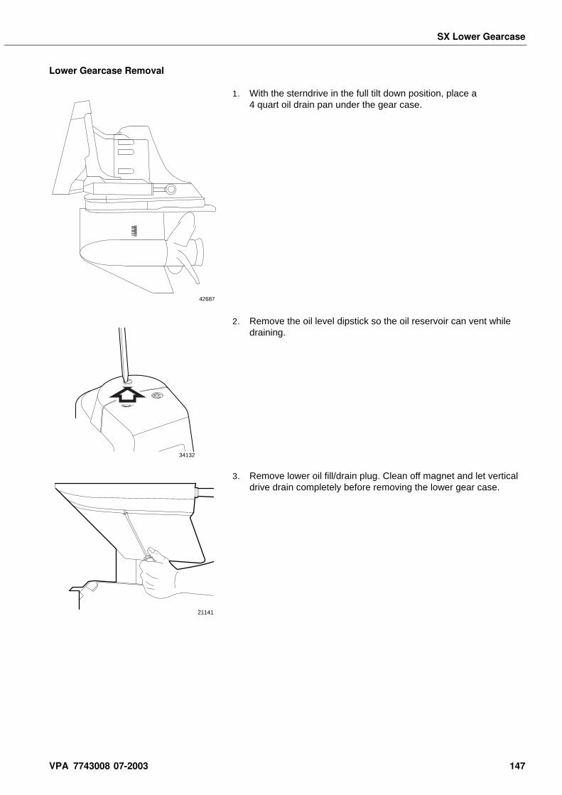
SX Lower Gearcase
Lower Gearcase Removal
1. With the sterndrive in the full tilt down position, place a 4 quart oil drain pan under the gear case.
2. Remove the oil level dipstick so the oil reservoir can vent while draining.
3. Remove lower oil fill/drain plug. Clean off magnet and let vertical drive drain completely before removing the lower gear case.
42687
34132
21141
VPA 7743008 07-2003 147
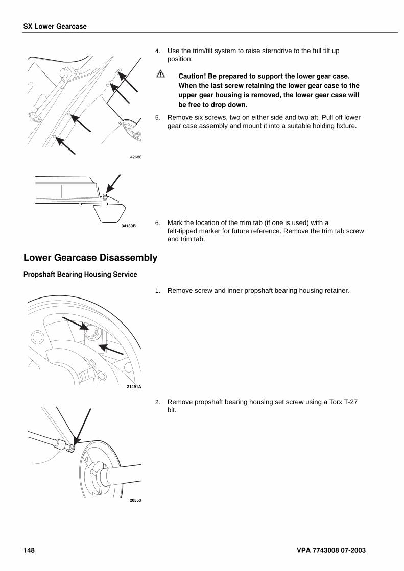
SX Lower Gearcase
4. Use the trim/tilt system to raise sterndrive to the full tilt up position.
Caution! Be prepared to support the lower gear case. When the last screw retaining the lower gear case to the upper gear housing is removed, the lower gear case will be free to drop down.
5. Remove six screws, two on either side and two aft. Pull off lower gear case assembly and mount it into a suitable holding fixture.
6. Mark the location of the trim tab (if one is used) with a felt-tipped marker for future reference. Remove the trim tab screw and trim tab.
Lower Gearcase Disassembly
Propshaft Bearing Housing Service
1. Remove screw and inner propshaft bearing housing retainer.
2. Remove propshaft bearing housing set screw using a Torx T-27 bit.
42688
34130B
21491A
20553
148 VPA 7743008 07-2003
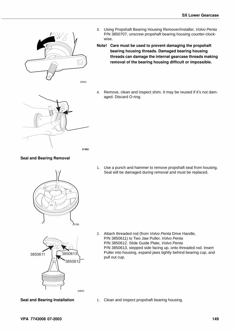
SX Lower Gearcase
3. Using Propshaft Bearing Housing Remover/installer, Volvo Penta P/N 3850707, unscrew propshaft bearing housing counter-clock-wise.
Note! Care must be used to prevent damaging the propshaft bearing housing threads. Damaged bearing housing threads can damage the internal gearcase threads making removal of the bearing housing difficult or impossible.
4. Remove, clean and inspect shim. It may be reused if it’s not dam-aged. Discard O-ring.
Seal and Bearing Removal
1. Use a punch and hammer to remove propshaft seal from housing. Seal will be damaged during removal and must be replaced.
2. Attach threaded rod (from Volvo Penta Drive Handle, P/N 3850611) to Two Jaw Puller, Volvo Penta P/N 3850612. Slide Guide Plate, Volvo Penta P/N 3850613, stepped side facing up, onto threaded rod. Insert Puller into housing, expand jaws tightly behind bearing cup, and pull out cup.
Seal and Bearing Installation 1. Clean and inspect propshaft bearing housing.
20551
21483
20789
3850611
3850612
3850613
33853
VPA 7743008 07-2003 149
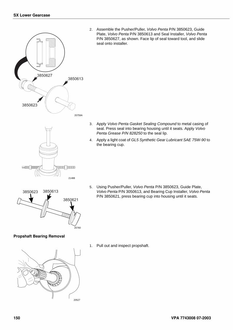
SX Lower Gearcase
2. Assemble the Pusher/Puller, Volvo Penta P/N 3850623, Guide Plate, Volvo Penta P/N 3850613 and Seal Installer, Volvo Penta P/N 3850627, as shown. Face lip of seal toward tool, and slide seal onto installer.
3. Apply Volvo Penta Gasket Sealing Compound to metal casing of seal. Press seal into bearing housing until it seats. Apply Volvo Penta Grease P/N 828250 to the seal lip.
4. Apply a light coat of GL5 Synthetic Gear Lubricant SAE 75W-90 to the bearing cup.
5. Using Pusher/Puller, Volvo Penta P/N 3850623, Guide Plate, Volvo Penta P/N 3050613, and Bearing Cup Installer, Volvo Penta P/N 3850621, press bearing cup into housing until it seats.
Propshaft Bearing Removal
1. Pull out and inspect propshaft.
20759A
3850627
3850623
3850613
21488
3850623 3850613
3850621
20760
20527
150 VPA 7743008 07-2003
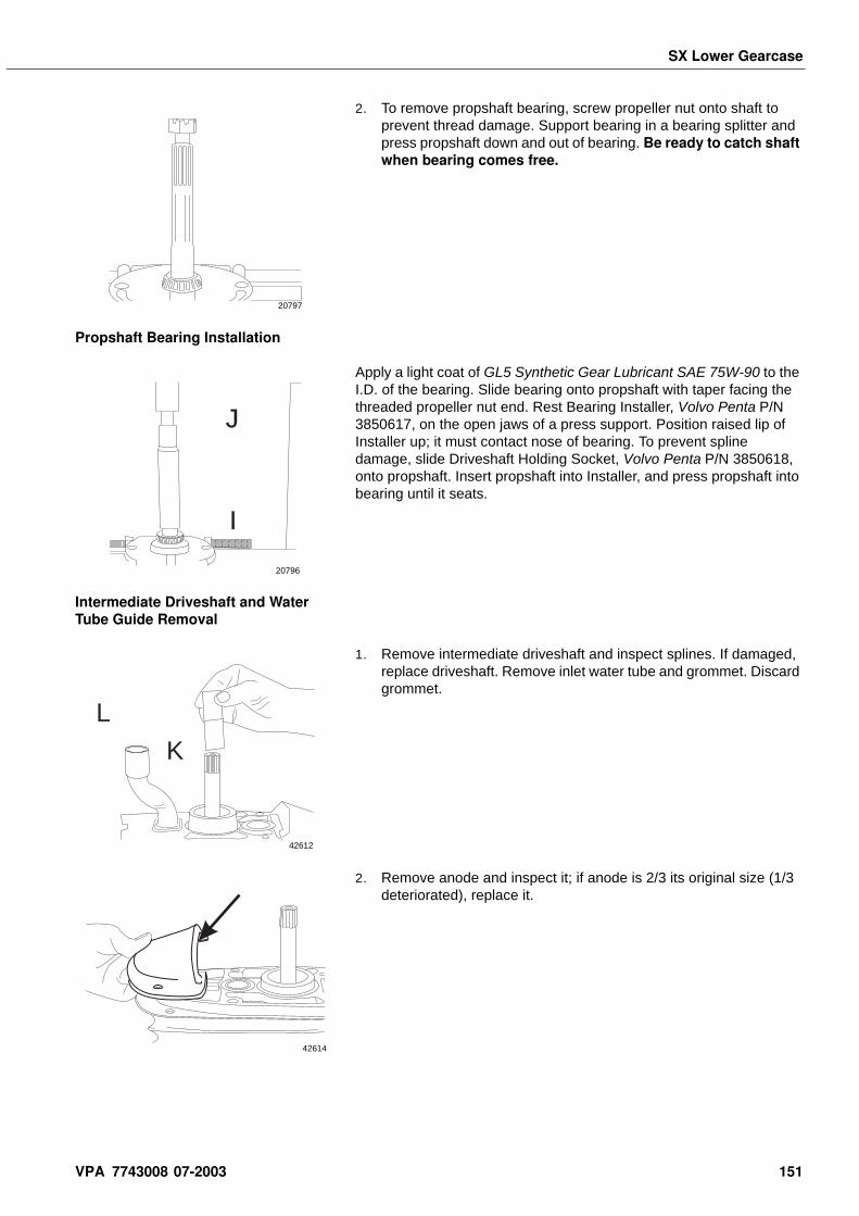
SX Lower Gearcase
2. To remove propshaft bearing, screw propeller nut onto shaft to prevent thread damage. Support bearing in a bearing splitter and press propshaft down and out of bearing. Be ready to catch shaft when bearing comes free.
Propshaft Bearing Installation
Apply a light coat of GL5 Synthetic Gear Lubricant SAE 75W-90 to the I.D. of the bearing. Slide bearing onto propshaft with taper facing the threaded propeller nut end. Rest Bearing Installer, Volvo Penta P/N 3850617, on the open jaws of a press support. Position raised lip of Installer up; it must contact nose of bearing. To prevent spline damage, slide Driveshaft Holding Socket, Volvo Penta P/N 3850618, onto propshaft. Insert propshaft into Installer, and press propshaft into bearing until it seats.
Intermediate Driveshaft and Water Tube Guide Removal
1. Remove intermediate driveshaft and inspect splines. If damaged, replace driveshaft. Remove inlet water tube and grommet. Discard grommet.
2. Remove anode and inspect it; if anode is 2/3 its original size (1/3 deteriorated), replace it.
20797
I
J
20796
L
K
42612
42614
VPA 7743008 07-2003 151
SX Lower Gearcase
3. Remove inlet water tube seal and retainer. If seal or retainer are damaged, replace them.
4. Remove and discard oil passage O-ring.
Driveshaft and Gear Removal
1. Using Spanner Wrench, Volvo Penta P/N 3850601, or Joint Ven-ture P/N 3850601, unscrew retainer and O-ring. Discard O-ring.
2. Screw Pinion Nut Holder, Volvo Penta P/N 3854864, or Joint Ven-ture P/N 3854864, onto Handle, Volvo Penta P/N 3850609. Slide Alignment Plate, Volvo Penta P/N 3850613, onto handle.
B
A
42615A
42616
3850601D
E
42617
3854864
3850609
3850613
33821A
152 VPA 7743008 07-2003
SX Lower Gearcase
3. Insert pinion nut holder pilot into drive gear. Turn the driveshaft to align pinion nut with holder. Slide Spline Socket, Volvo Penta P/N 3850598 onto driveshaft.
4. To remove pinion nut, turn driveshaft counter-clockwise.
5. Remove and retain pinion nut and pinion. The nut will be used later for shimming.
6. Lift out driveshaft assembly, then remove propeller shaft gear assembly.
3850598
I
42618
42619
33818
33842
VPA 7743008 07-2003 153
SX Lower Gearcase
7. The 19 pinion roller bearings may fall out of the retainer; remove and retain the roller bearings.
8. Use a three-jaw puller such as Owatonna Tool, P/N 1176, to remove the bearing cup and shims.
Note! The shims will be damaged during removal and must be replaced on reassembly.
9. Do not remove propshaft gear bearing unless you intend to replace it. Removal process may damage bearing. Use a bear-ing separator to support the bearing. Insert Bearing Remover, Volvo Penta P/N 3850625, and Handle, Volvo Penta P/N 3850610, into gear, then press gear out of bearing.
10. Do not remove oil slinger from gear unless you intend to replace it. Removal process may damage oil slinger. Use a bearing separator to support the oil slinger, and press gear out of oil slinger.
21435
20793
38506103850625
20795
33848
154 VPA 7743008 07-2003
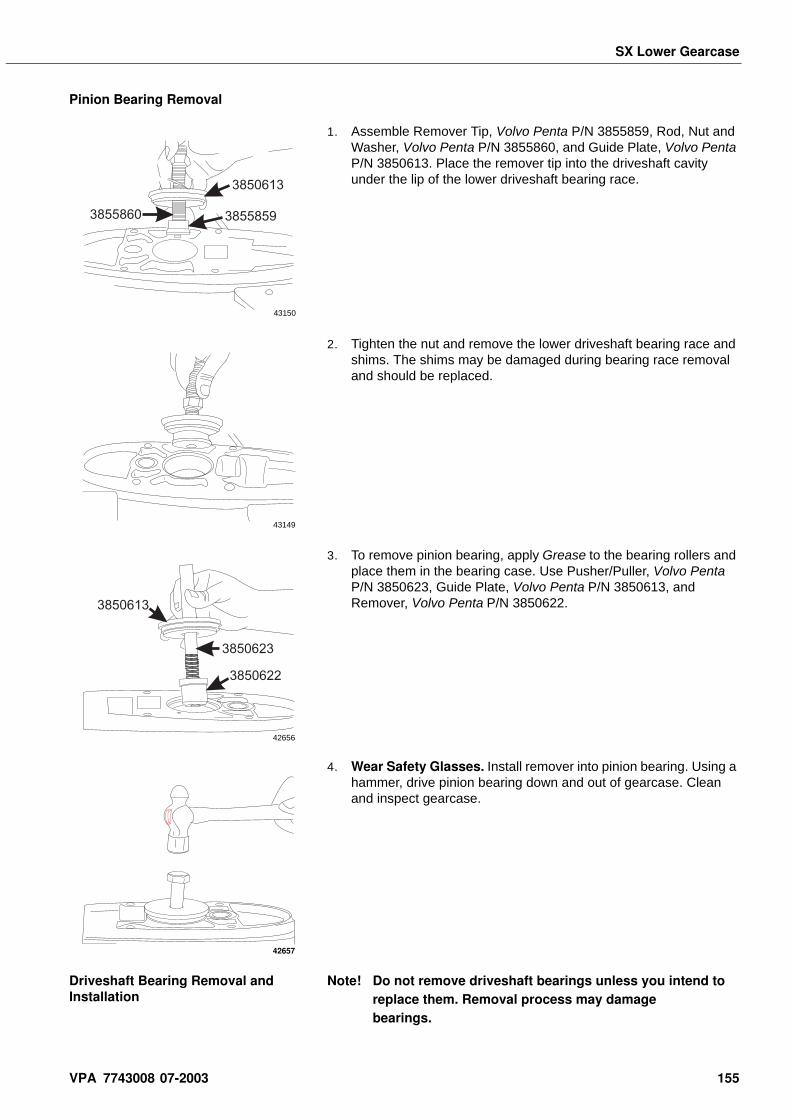
SX Lower Gearcase
Pinion Bearing Removal
1. Assemble Remover Tip, Volvo Penta P/N 3855859, Rod, Nut and Washer, Volvo Penta P/N 3855860, and Guide Plate, Volvo Penta P/N 3850613. Place the remover tip into the driveshaft cavity under the lip of the lower driveshaft bearing race.
2. Tighten the nut and remove the lower driveshaft bearing race and shims. The shims may be damaged during bearing race removal and should be replaced.
3. To remove pinion bearing, apply Grease to the bearing rollers and place them in the bearing case. Use Pusher/Puller, Volvo Penta P/N 3850623, Guide Plate, Volvo Penta P/N 3850613, and Remover, Volvo Penta P/N 3850622.
4. Wear Safety Glasses. Install remover into pinion bearing. Using a hammer, drive pinion bearing down and out of gearcase. Clean and inspect gearcase.
Driveshaft Bearing Removal and Installation
Note! Do not remove driveshaft bearings unless you intend to replace them. Removal process may damage bearings.
38558593855860
3850613
43150
43149
3850623
3850613
3850622
42656
42657
VPA 7743008 07-2003 155
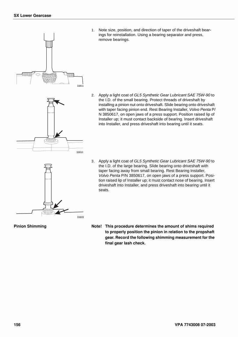
SX Lower Gearcase
1. Note size, position, and direction of taper of the driveshaft bear-ings for reinstallation. Using a bearing separator and press, remove bearings.
2. Apply a light coat of GL5 Synthetic Gear Lubricant SAE 75W-90 to the I.D. of the small bearing. Protect threads of driveshaft by installing a pinion nut onto driveshaft. Slide bearing onto driveshaft with taper facing pinion end. Rest Bearing Installer, Volvo Penta P/N 3850617, on open jaws of a press support. Position raised lip of Installer up; it must contact backside of bearing. Insert driveshaft into Installer, and press driveshaft into bearing until it seats.
3. Apply a light coat of GL5 Synthetic Gear Lubricant SAE 75W-90 to the I.D. of the large bearing. Slide bearing onto driveshaft with taper facing away from small bearing. Rest Bearing Installer, Volvo Penta P/N 3850617, on open jaws of a press support. Posi-tion raised lip of Installer up; it must contact nose of bearing. Insert driveshaft into Installer, and press driveshaft into bearing until it seats.
Pinion Shimming Note! This procedure determines the amount of shims required to properly position the pinion in relation to the propshaft gear. Record the following shimming measurement for the final gear lash check.
33811
33810
33809
156 VPA 7743008 07-2003
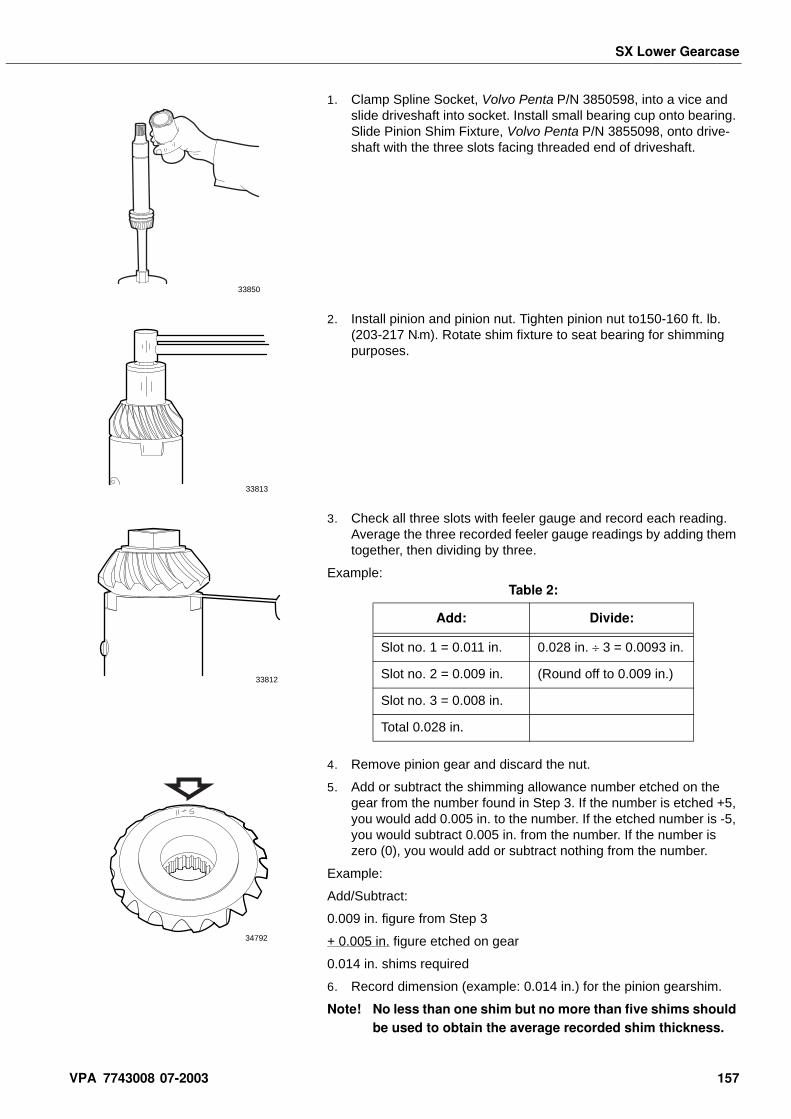
SX Lower Gearcase
1. Clamp Spline Socket, Volvo Penta P/N 3850598, into a vice and slide driveshaft into socket. Install small bearing cup onto bearing. Slide Pinion Shim Fixture, Volvo Penta P/N 3855098, onto drive-shaft with the three slots facing threaded end of driveshaft.
2. Install pinion and pinion nut. Tighten pinion nut to150-160 ft. lb. (203-217 N•m). Rotate shim fixture to seat bearing for shimming purposes.
3. Check all three slots with feeler gauge and record each reading. Average the three recorded feeler gauge readings by adding them together, then dividing by three.
Example:
4. Remove pinion gear and discard the nut.
5. Add or subtract the shimming allowance number etched on the gear from the number found in Step 3. If the number is etched +5, you would add 0.005 in. to the number. If the etched number is -5, you would subtract 0.005 in. from the number. If the number is zero (0), you would add or subtract nothing from the number.
Example:
Add/Subtract:
0.009 in. figure from Step 3
+ 0.005 in. figure etched on gear
0.014 in. shims required
6. Record dimension (example: 0.014 in.) for the pinion gearshim.
Note! No less than one shim but no more than five shims should be used to obtain the average recorded shim thickness.
33850
33813
33812
Table 2:
Add: Divide:
Slot no. 1 = 0.011 in. 0.028 in. ÷ 3 = 0.0093 in.
Slot no. 2 = 0.009 in. (Round off to 0.009 in.)
Slot no. 3 = 0.008 in.
Total 0.028 in.
34792
VPA 7743008 07-2003 157
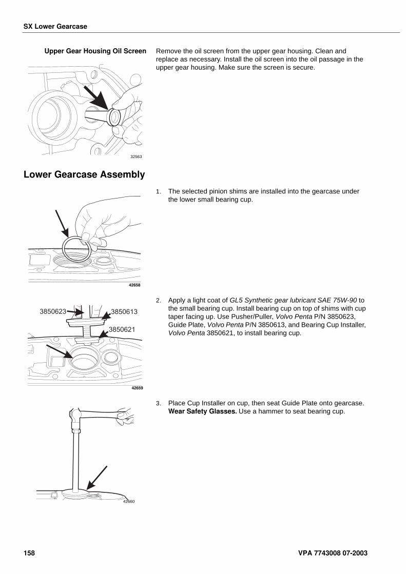
SX Lower Gearcase
Upper Gear Housing Oil Screen Remove the oil screen from the upper gear housing. Clean and replace as necessary. Install the oil screen into the oil passage in the upper gear housing. Make sure the screen is secure.
Lower Gearcase Assembly
1. The selected pinion shims are installed into the gearcase under the lower small bearing cup.
2. Apply a light coat of GL5 Synthetic gear lubricant SAE 75W-90 to the small bearing cup. Install bearing cup on top of shims with cup taper facing up. Use Pusher/Puller, Volvo Penta P/N 3850623, Guide Plate, Volvo Penta P/N 3850613, and Bearing Cup Installer, Volvo Penta 3850621, to install bearing cup.
3. Place Cup Installer on cup, then seat Guide Plate onto gearcase. Wear Safety Glasses. Use a hammer to seat bearing cup.
32563
42658
3850623 3850613
3850621
42659
42660
158 VPA 7743008 07-2003
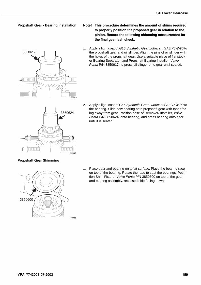
SX Lower Gearcase
Propshaft Gear - Bearing Installation Note! This procedure determines the amount of shims required to properly position the propshaft gear in relation to the pinion. Record the following shimming measurement for the final gear lash check.
1. Apply a light coat of GL5 Synthetic Gear Lubricant SAE 75W-90 to the propshaft gear and oil slinger. Align the pins of oil slinger with the holes of the propshaft gear. Use a suitable piece of flat stock or Bearing Separator, and Propshaft Bearing Installer, Volvo Penta P/N 3850617, to press oil slinger onto gear until seated.
2. Apply a light coat of GL5 Synthetic Gear Lubricant SAE 75W-90 to the bearing. Slide new bearing onto propshaft gear with taper fac-ing away from gear. Position nose of Remover/ Installer, Volvo Penta P/N 3850624, onto bearing, and press bearing onto gear until it is seated.
Propshaft Gear Shimming
1. Place gear and bearing on a flat surface. Place the bearing race on top of the bearing. Rotate the race to seat the bearings. Posi-tion Shim Fixture, Volvo Penta P/N 3850600 on top of the gear and bearing assembly, recessed side facing down.
3850617
33849
3850624
33847
3850600
34788
VPA 7743008 07-2003 159
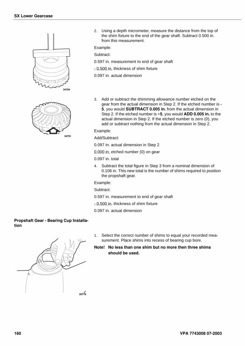
SX Lower Gearcase
2. Using a depth micrometer, measure the distance from the top of the shim fixture to the end of the gear shaft. Subtract 0.500 in. from this measurement.
Example:
Subtract:
0.597 in. measurement to end of gear shaft
- 0.500 in. thickness of shim fixture
0.097 in. actual dimension
3. Add or subtract the shimming allowance number etched on the gear from the actual dimension in Step 2. If the etched number is -5, you would SUBTRACT 0.005 in. from the actual dimension in Step 2. If the etched number is +5, you would ADD 0.005 in. to the actual dimension in Step 2. If the etched number is zero (0), you add or subtract nothing from the actual dimension in Step 2.
Example:
Add/Subtract:
0.097 in. actual dimension in Step 2
0.000 in. etched number (0) on gear
0.097 in. total
4. Subtract the total figure in Step 3 from a nominal dimension of 0.106 in. This new total is the number of shims required to position the propshaft gear.
Example:
Subtract:
0.597 in. measurement to end of gear shaft
- 0.500 in. thickness of shim fixture
0.097 in. actual dimension
Propshaft Gear - Bearing Cup Installa-tion
1. Select the correct number of shims to equal your recorded mea-surement. Place shims into recess of bearing cup bore.
Note! No less than one shim but no more then three shims should be used.
34794
34791
20778
160 VPA 7743008 07-2003
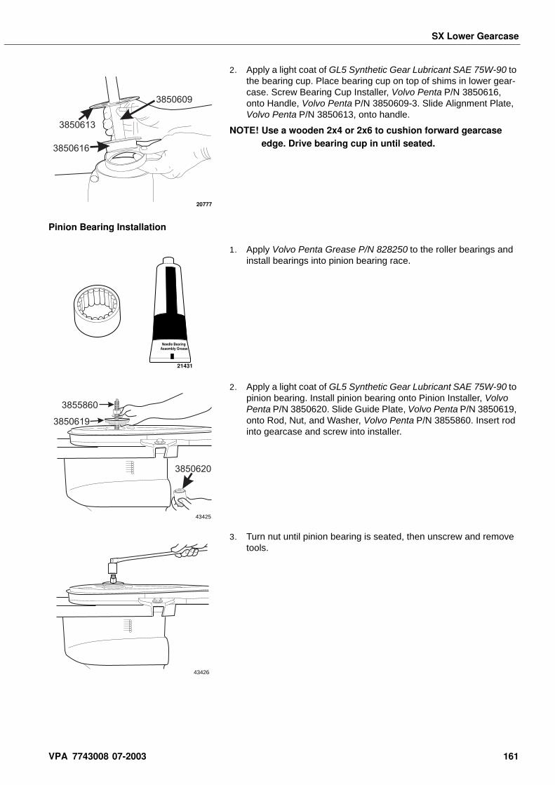
SX Lower Gearcase
2. Apply a light coat of GL5 Synthetic Gear Lubricant SAE 75W-90 to the bearing cup. Place bearing cup on top of shims in lower gear-case. Screw Bearing Cup Installer, Volvo Penta P/N 3850616, onto Handle, Volvo Penta P/N 3850609-3. Slide Alignment Plate, Volvo Penta P/N 3850613, onto handle.
NOTE! Use a wooden 2x4 or 2x6 to cushion forward gearcase edge. Drive bearing cup in until seated.
Pinion Bearing Installation
1. Apply Volvo Penta Grease P/N 828250 to the roller bearings and install bearings into pinion bearing race.
2. Apply a light coat of GL5 Synthetic Gear Lubricant SAE 75W-90 to pinion bearing. Install pinion bearing onto Pinion Installer, Volvo Penta P/N 3850620. Slide Guide Plate, Volvo Penta P/N 3850619, onto Rod, Nut, and Washer, Volvo Penta P/N 3855860. Insert rod into gearcase and screw into installer.
3. Turn nut until pinion bearing is seated, then unscrew and remove tools.
3850616
3850609
3850613
20777
21431
3850620
3850619
3855860
43425
43426
VPA 7743008 07-2003 161
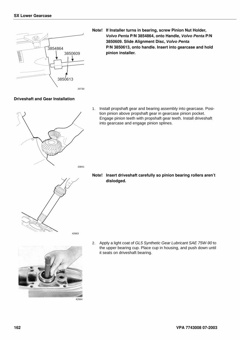
SX Lower Gearcase
Note! If Installer turns in bearing, screw Pinion Nut Holder, Volvo Penta P/N 3854864, onto Handle, Volvo Penta P/N 3850609. Slide Alignment Disc, Volvo Penta P/N 3850613, onto handle. Insert into gearcase and hold pinion installer.
Driveshaft and Gear Installation
1. Install propshaft gear and bearing assembly into gearcase. Posi-tion pinion above propshaft gear in gearcase pinion pocket. Engage pinion teeth with propshaft gear teeth. Install driveshaft into gearcase and engage pinion splines.
Note! Insert driveshaft carefully so pinion bearing rollers aren’t dislodged.
2. Apply a light coat of GL5 Synthetic Gear Lubricant SAE 75W-90 to the upper bearing cup. Place cup in housing, and push down until it seats on driveshaft bearing.
3854864
3850609
3850613
20730
33841
42663
42664
162 VPA 7743008 07-2003
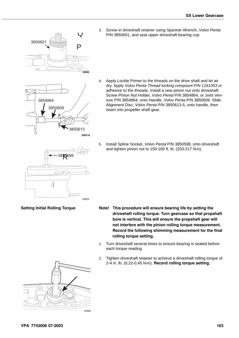
SX Lower Gearcase
3. Screw in driveshaft retainer using Spanner Wrench, Volvo Penta P/N 3850601, and seat upper driveshaft bearing cup.
4. Apply Loctite Primer to the threads on the drive shaft and let air dry. Apply Volvo Penta Thread locking compount P/N 1161053 or adhesive to the threads. Install a new pinion nut onto driveshaft. Screw Pinion Nut Holder, Volvo Penta P/N 3854864, or Joint Ven-ture P/N 3854864, onto Handle, Volvo Penta P/N 3850609. Slide Alignment Disc, Volvo Penta P/N 3850613-5, onto handle, then insert into propeller shaft gear.
5. Install Spline Socket, Volvo Penta P/N 3850598, onto driveshaft and tighten pinion nut to 150-160 ft. lb. (203-217 N•m).
Setting Initial Rolling Torque Note! This procedure will ensure bearing life by setting the driveshaft rolling torque. Turn gearcase so that propshaft bore is vertical. This will ensure the propshaft gear will not interfere with the pinion rolling torque measurement. Record the following shimming measurement for the final rolling torque setting.
1. Turn driveshaft several times to ensure bearing is seated before each torque reading.
2. Tighten driveshaft retainer to achieve a driveshaft rolling torque of 2-4 in. lb. (0,22-0,45 N•m). Record rolling torque setting.
Q
P3850601
42665
3854864
3850609
3850613
33821A
R3850598
33829
42666
VPA 7743008 07-2003 163
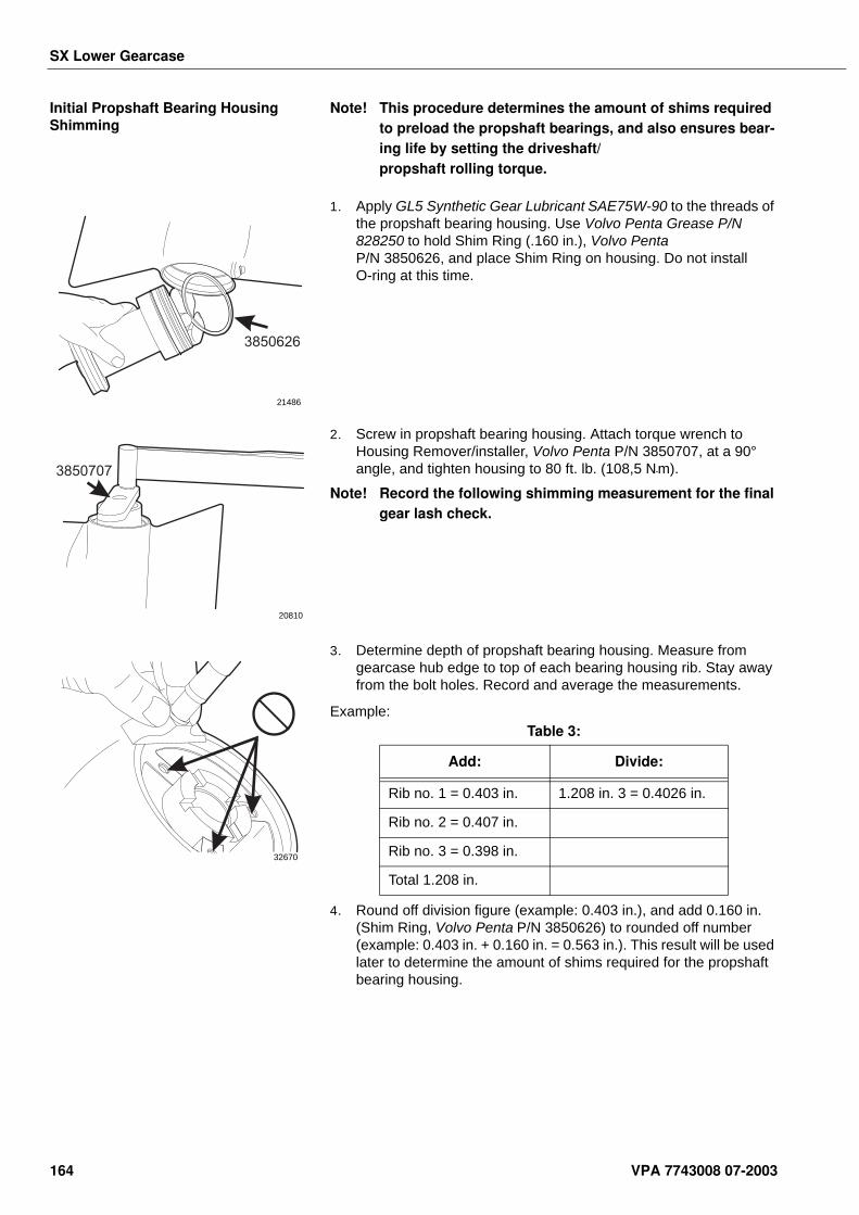
SX Lower Gearcase
Initial Propshaft Bearing Housing Shimming
Note! This procedure determines the amount of shims required to preload the propshaft bearings, and also ensures bear-ing life by setting the driveshaft/propshaft rolling torque.
1. Apply GL5 Synthetic Gear Lubricant SAE75W-90 to the threads of the propshaft bearing housing. Use Volvo Penta Grease P/N 828250 to hold Shim Ring (.160 in.), Volvo Penta P/N 3850626, and place Shim Ring on housing. Do not install O-ring at this time.
2. Screw in propshaft bearing housing. Attach torque wrench to Housing Remover/installer, Volvo Penta P/N 3850707, at a 90° angle, and tighten housing to 80 ft. lb. (108,5 N•m).
Note! Record the following shimming measurement for the final gear lash check.
3. Determine depth of propshaft bearing housing. Measure from gearcase hub edge to top of each bearing housing rib. Stay away from the bolt holes. Record and average the measurements.
Example:
4. Round off division figure (example: 0.403 in.), and add 0.160 in. (Shim Ring, Volvo Penta P/N 3850626) to rounded off number (example: 0.403 in. + 0.160 in. = 0.563 in.). This result will be used later to determine the amount of shims required for the propshaft bearing housing.
3850626
21486
3850707
20810
32670
Table 3:
Add: Divide:
Rib no. 1 = 0.403 in. 1.208 in. 3 = 0.4026 in.
Rib no. 2 = 0.407 in.
Rib no. 3 = 0.398 in.
Total 1.208 in.
164 VPA 7743008 07-2003
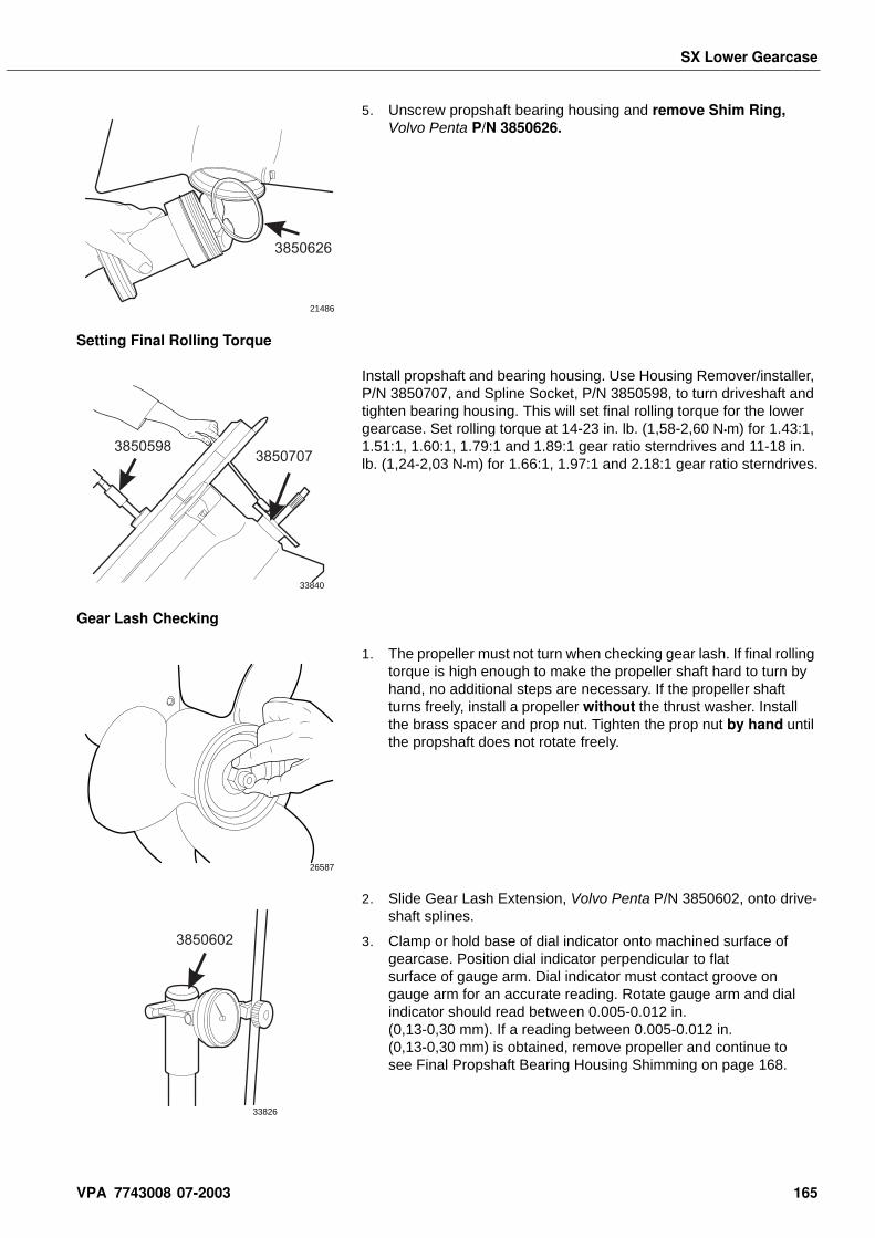
SX Lower Gearcase
5. Unscrew propshaft bearing housing and remove Shim Ring, Volvo Penta P/N 3850626.
Setting Final Rolling Torque
Install propshaft and bearing housing. Use Housing Remover/installer, P/N 3850707, and Spline Socket, P/N 3850598, to turn driveshaft and tighten bearing housing. This will set final rolling torque for the lower gearcase. Set rolling torque at 14-23 in. lb. (1,58-2,60 N•m) for 1.43:1, 1.51:1, 1.60:1, 1.79:1 and 1.89:1 gear ratio sterndrives and 11-18 in. lb. (1,24-2,03 N•m) for 1.66:1, 1.97:1 and 2.18:1 gear ratio sterndrives.
Gear Lash Checking
1. The propeller must not turn when checking gear lash. If final rolling torque is high enough to make the propeller shaft hard to turn by hand, no additional steps are necessary. If the propeller shaft turns freely, install a propeller without the thrust washer. Install the brass spacer and prop nut. Tighten the prop nut by hand until the propshaft does not rotate freely.
2. Slide Gear Lash Extension, Volvo Penta P/N 3850602, onto drive-shaft splines.
3. Clamp or hold base of dial indicator onto machined surface of gearcase. Position dial indicator perpendicular to flat surface of gauge arm. Dial indicator must contact groove on gauge arm for an accurate reading. Rotate gauge arm and dial indicator should read between 0.005-0.012 in. (0,13-0,30 mm). If a reading between 0.005-0.012 in. (0,13-0,30 mm) is obtained, remove propeller and continue to see Final Propshaft Bearing Housing Shimming on page 168.
3850626
21486
38507073850598
33840
26587
3850602
33826
VPA 7743008 07-2003 165
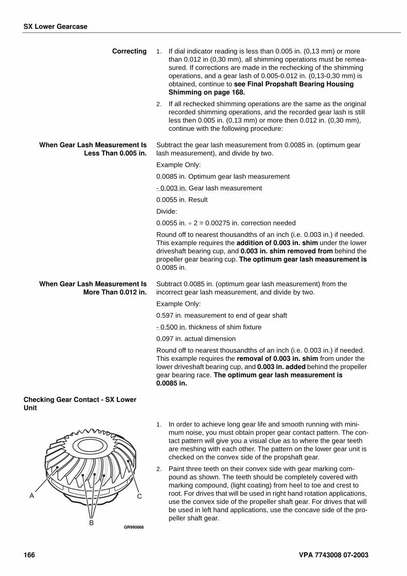
SX Lower Gearcase
Correcting 1. If dial indicator reading is less than 0.005 in. (0,13 mm) or more than 0.012 in (0,30 mm), all shimming operations must be remea-sured. If corrections are made in the rechecking of the shimming operations, and a gear lash of 0.005-0.012 in. (0,13-0,30 mm) is obtained, continue to see Final Propshaft Bearing Housing Shimming on page 168.
2. If all rechecked shimming operations are the same as the original recorded shimming operations, and the recorded gear lash is still less then 0.005 in. (0,13 mm) or more then 0.012 in. (0,30 mm), continue with the following procedure:
When Gear Lash Measurement IsLess Than 0.005 in.
Subtract the gear lash measurement from 0.0085 in. (optimum gear lash measurement), and divide by two.
Example Only:
0.0085 in. Optimum gear lash measurement
- 0.003 in. Gear lash measurement
0.0055 in. Result
Divide:
0.0055 in. ÷ 2 = 0.00275 in. correction needed
Round off to nearest thousandths of an inch (i.e. 0.003 in.) if needed. This example requires the addition of 0.003 in. shim under the lower driveshaft bearing cup, and 0.003 in. shim removed from behind the propeller gear bearing cup. The optimum gear lash measurement is 0.0085 in.
When Gear Lash Measurement IsMore Than 0.012 in.
Subtract 0.0085 in. (optimum gear lash measurement) from the incorrect gear lash measurement, and divide by two.
Example Only:
0.597 in. measurement to end of gear shaft
- 0.500 in. thickness of shim fixture
0.097 in. actual dimension
Round off to nearest thousandths of an inch (i.e. 0.003 in.) if needed. This example requires the removal of 0.003 in. shim from under the lower driveshaft bearing cup, and 0.003 in. added behind the propeller gear bearing race. The optimum gear lash measurement is 0.0085 in.
Checking Gear Contact - SX Lower Unit
1. In order to achieve long gear life and smooth running with mini-mum noise, you must obtain proper gear contact pattern. The con-tact pattern will give you a visual clue as to where the gear teeth are meshing with each other. The pattern on the lower gear unit is checked on the convex side of the propshaft gear.
2. Paint three teeth on their convex side with gear marking com-pound as shown. The teeth should be completely covered with marking compound, (light coating) from heel to toe and crest to root. For drives that will be used in right hand rotation applications, use the convex side of the propeller shaft gear. For drives that will be used in left hand applications, use the concave side of the pro-peller shaft gear.
A
B
C
GR990868
166 VPA 7743008 07-2003
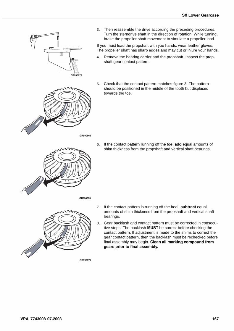
SX Lower Gearcase
3. Then reassemble the drive according the preceding procedures. Turn the sterndrive shaft in the direction of rotation. While turning, brake the propeller shaft movement to simulate a propeller load.
If you must load the propshaft with you hands, wear leather gloves. The propeller shaft has sharp edges and may cut or injure your hands.
4. Remove the bearing carrier and the propshaft. Inspect the prop-shaft gear contact pattern.
5. Check that the contact pattern matches figure 3. The pattern should be positioned in the middle of the tooth but displaced towards the toe.
6. If the contact pattern running off the toe, add equal amounts of shim thickness from the propshaft and vertical shaft bearings.
7. It the contact pattern is running off the heel, subtract equal amounts of shim thickness from the propshaft and vertical shaft bearings.
8. Gear backlash and contact pattern must be corrected in consecu-tive steps. The backlash MUST be correct before checking the contact pattern. If adjustment is made to the shims to correct the gear contact pattern, then the backlash must be rechecked before final assembly may begin. Clean all marking compound from gears prior to final assembly.
GR990879
GR990869
GR990870
GR990871
VPA 7743008 07-2003 167
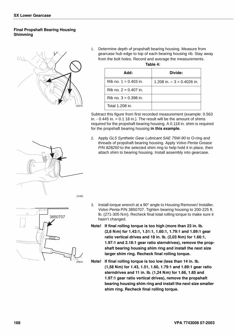
SX Lower Gearcase
Final Propshaft Bearing Housing Shimming
1. Determine depth of propshaft bearing housing. Measure from gearcase hub edge to top of each bearing housing rib. Stay away from the bolt holes. Record and average the measurements.
Subtract this figure from first recorded measurement (example: 0.563 in. - 0.445 in. = 0.1 18 in.). The result will be the amount of shims required for the propshaft bearing housing. A 0.118 in. shim is required for the propshaft bearing housing in this example.
2. Apply GL5 Synthetic Gear Lubricant SAE 75W-90 to O-ring and threads of propshaft bearing housing. Apply Volvo Penta Grease P/N 828250 to the selected shim ring to help hold it in place, then attach shim to bearing housing. Install assembly into gearcase.
3. Install torque wrench at a 90° angle to Housing Remover/ Installer, Volvo Penta P/N 3850707. Tighten bearing housing to 200-225 ft. lb. (271-305 N•m). Recheck final total rolling torque to make sure it hasn’t changed.
Note! If final rolling torque is too high (more than 23 in. lb. (2,6 N•m) for 1.43:1, 1.51:1, 1.60:1, 1.79:1 and 1.89:1 gear ratio vertical drives and 18 in. lb. (2,03 N•m) for 1.66:1, 1.97:1 and 2.18:1 gear ratio sterndrives), remove the prop-shaft bearing housing shim ring and install the next size larger shim ring. Recheck final rolling torque.
Note! If final rolling torque is too low (less than 14 in. lb. (1,58 N•m) for 1.43, 1.51, 1.60, 1.79:1 and 1.89:1 gear ratio sterndrives and 11 in. lb. (1,24 N•m) for 1.66, 1.85 and 1.97:1 gear ratio vertical drives), remove the propshaft bearing housing shim ring and install the next size smaller shim ring. Recheck final rolling torque.
32670
Table 4:
Add: Divide:
Rib no. 1 = 0.403 in. 1.208 in. ÷ 3 = 0.4026 in.
Rib no. 2 = 0.407 in.
Rib no. 3 = 0.398 in.
Total 1.208 in.
21483
3850707
20815
168 VPA 7743008 07-2003
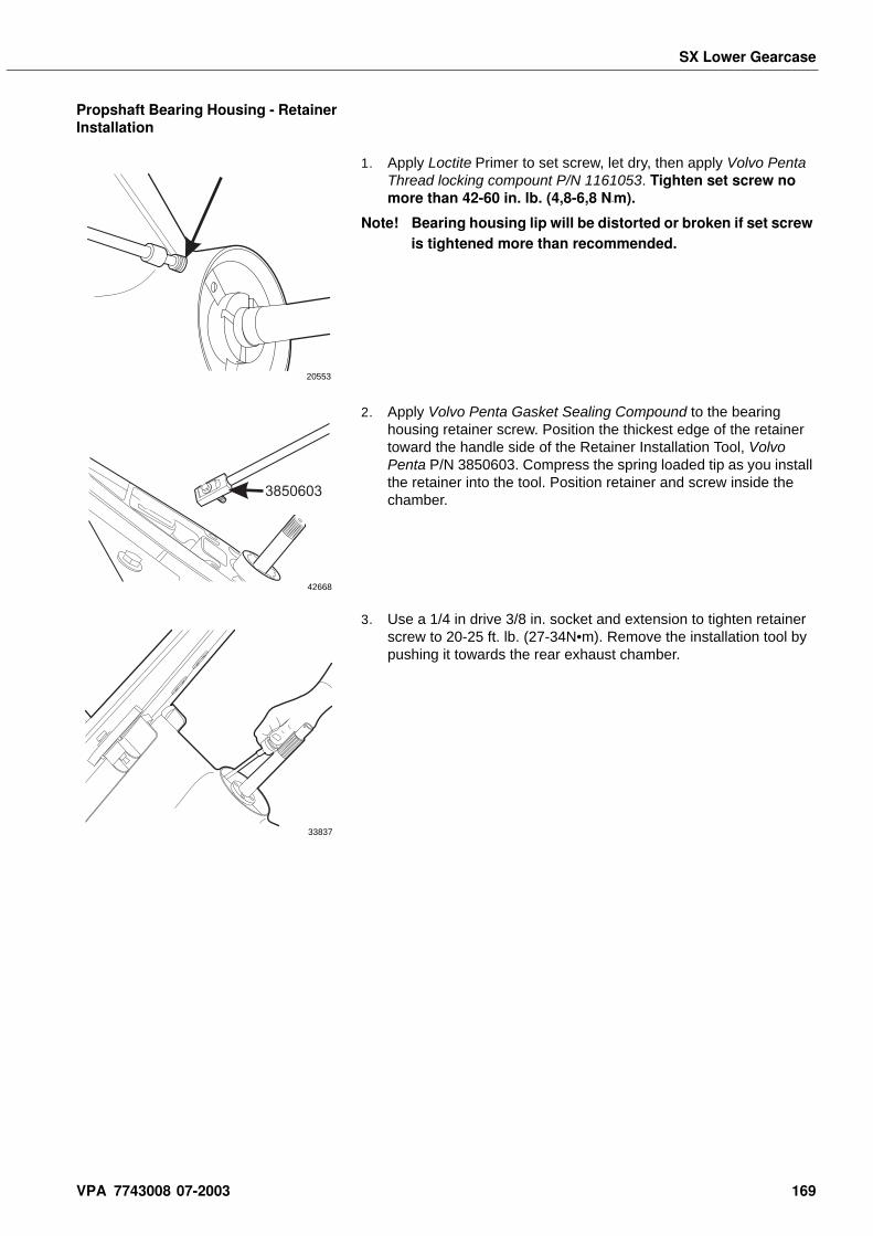
SX Lower Gearcase
Propshaft Bearing Housing - Retainer Installation
1. Apply Loctite Primer to set screw, let dry, then apply Volvo Penta Thread locking compount P/N 1161053. Tighten set screw no more than 42-60 in. lb. (4,8-6,8 N•m).
Note! Bearing housing lip will be distorted or broken if set screw is tightened more than recommended.
2. Apply Volvo Penta Gasket Sealing Compound to the bearing housing retainer screw. Position the thickest edge of the retainer toward the handle side of the Retainer Installation Tool, Volvo Penta P/N 3850603. Compress the spring loaded tip as you install the retainer into the tool. Position retainer and screw inside the chamber.
3. Use a 1/4 in drive 3/8 in. socket and extension to tighten retainer screw to 20-25 ft. lb. (27-34N•m). Remove the installation tool by pushing it towards the rear exhaust chamber.
20553
3850603
42668
33837
VPA 7743008 07-2003 169
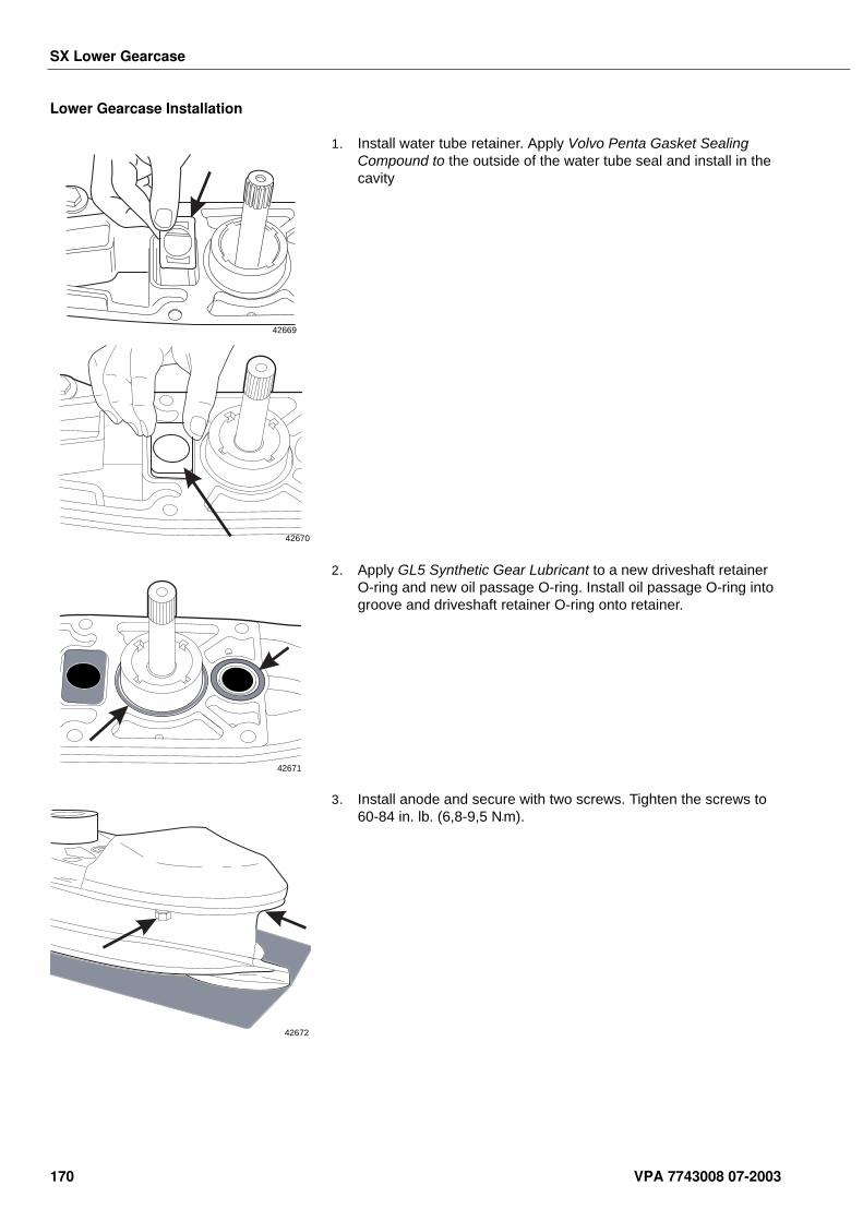
SX Lower Gearcase
Lower Gearcase Installation
1. Install water tube retainer. Apply Volvo Penta Gasket Sealing Compound to the outside of the water tube seal and install in the cavity
2. Apply GL5 Synthetic Gear Lubricant to a new driveshaft retainer O-ring and new oil passage O-ring. Install oil passage O-ring into groove and driveshaft retainer O-ring onto retainer.
3. Install anode and secure with two screws. Tighten the screws to 60-84 in. lb. (6,8-9,5 N•m).
42669
42670
42671
42672
170 VPA 7743008 07-2003
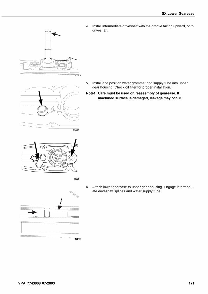
SX Lower Gearcase
4. Install intermediate driveshaft with the groove facing upward, onto driveshaft.
5. Install and position water grommet and supply tube into upper gear housing. Check oil filter for proper installation.
Note! Care must be used on reassembly of gearease. If machined surface is damaged, leakage may occur.
6. Attach lower gearcase to upper gear housing. Engage intermedi-ate driveshaft splines and water supply tube.
42609
39433
39389
42610
VPA 7743008 07-2003 171
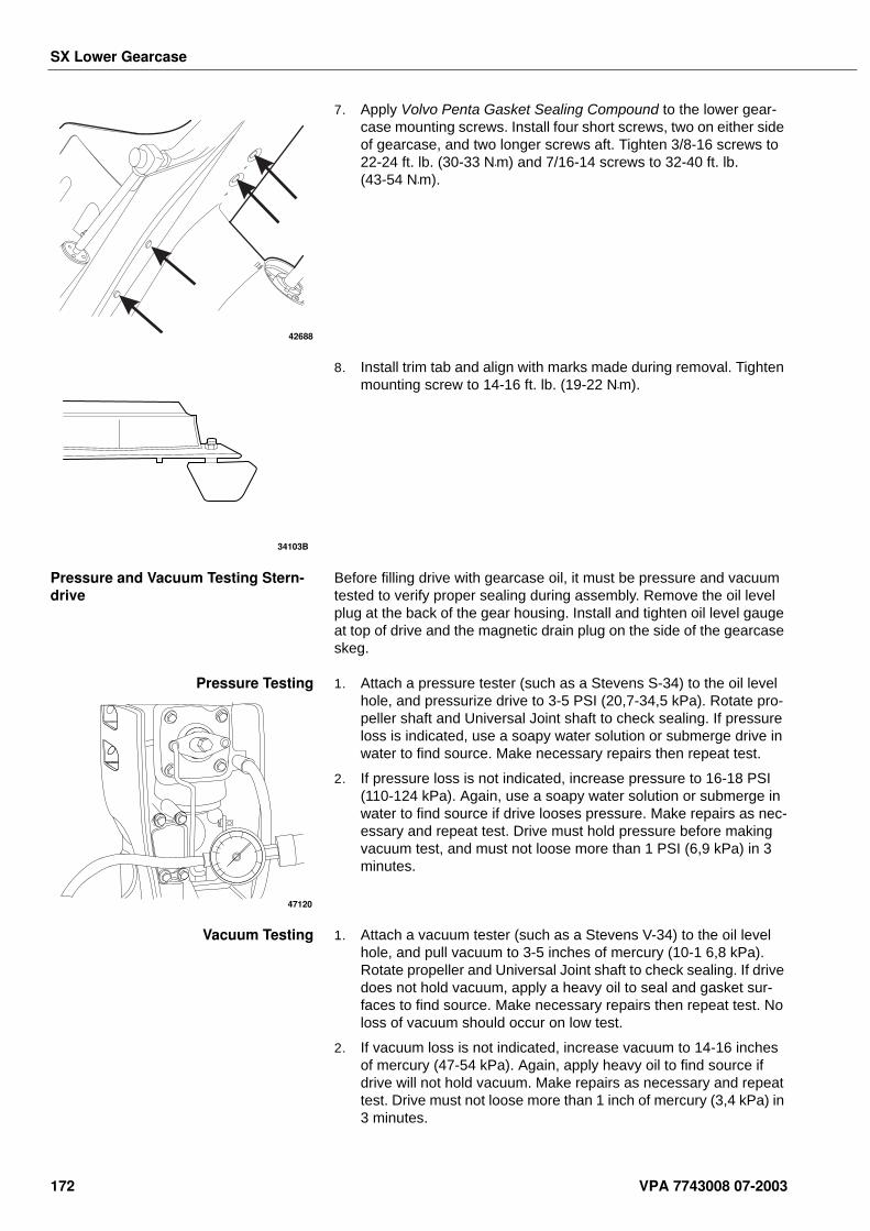
SX Lower Gearcase
7. Apply Volvo Penta Gasket Sealing Compound to the lower gear-case mounting screws. Install four short screws, two on either side of gearcase, and two longer screws aft. Tighten 3/8-16 screws to 22-24 ft. lb. (30-33 N•m) and 7/16-14 screws to 32-40 ft. lb. (43-54 N•m).
8. Install trim tab and align with marks made during removal. Tighten mounting screw to 14-16 ft. lb. (19-22 N•m).
Pressure and Vacuum Testing Stern-drive
Before filling drive with gearcase oil, it must be pressure and vacuum tested to verify proper sealing during assembly. Remove the oil level plug at the back of the gear housing. Install and tighten oil level gauge at top of drive and the magnetic drain plug on the side of the gearcase skeg.
Pressure Testing 1. Attach a pressure tester (such as a Stevens S-34) to the oil level hole, and pressurize drive to 3-5 PSI (20,7-34,5 kPa). Rotate pro-peller shaft and Universal Joint shaft to check sealing. If pressure loss is indicated, use a soapy water solution or submerge drive in water to find source. Make necessary repairs then repeat test.
2. If pressure loss is not indicated, increase pressure to 16-18 PSI (110-124 kPa). Again, use a soapy water solution or submerge in water to find source if drive looses pressure. Make repairs as nec-essary and repeat test. Drive must hold pressure before making vacuum test, and must not loose more than 1 PSI (6,9 kPa) in 3 minutes.
Vacuum Testing 1. Attach a vacuum tester (such as a Stevens V-34) to the oil level hole, and pull vacuum to 3-5 inches of mercury (10-1 6,8 kPa). Rotate propeller and Universal Joint shaft to check sealing. If drive does not hold vacuum, apply a heavy oil to seal and gasket sur-faces to find source. Make necessary repairs then repeat test. No loss of vacuum should occur on low test.
2. If vacuum loss is not indicated, increase vacuum to 14-16 inches of mercury (47-54 kPa). Again, apply heavy oil to find source if drive will not hold vacuum. Make repairs as necessary and repeat test. Drive must not loose more than 1 inch of mercury (3,4 kPa) in 3 minutes.
42688
34103B
47120
172 VPA 7743008 07-2003
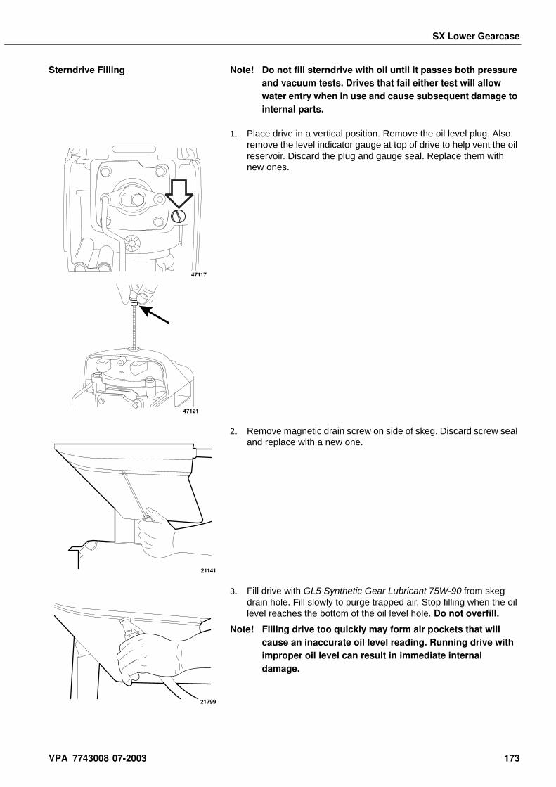
SX Lower Gearcase
Sterndrive Filling Note! Do not fill sterndrive with oil until it passes both pressure and vacuum tests. Drives that fail either test will allow water entry when in use and cause subsequent damage to internal parts.
1. Place drive in a vertical position. Remove the oil level plug. Also remove the level indicator gauge at top of drive to help vent the oil reservoir. Discard the plug and gauge seal. Replace them with new ones.
2. Remove magnetic drain screw on side of skeg. Discard screw seal and replace with a new one.
3. Fill drive with GL5 Synthetic Gear Lubricant 75W-90 from skeg drain hole. Fill slowly to purge trapped air. Stop filling when the oil level reaches the bottom of the oil level hole. Do not overfill.
Note! Filling drive too quickly may form air pockets that will cause an inaccurate oil level reading. Running drive with improper oil level can result in immediate internal damage.
47117
47121
21141
21799
VPA 7743008 07-2003 173
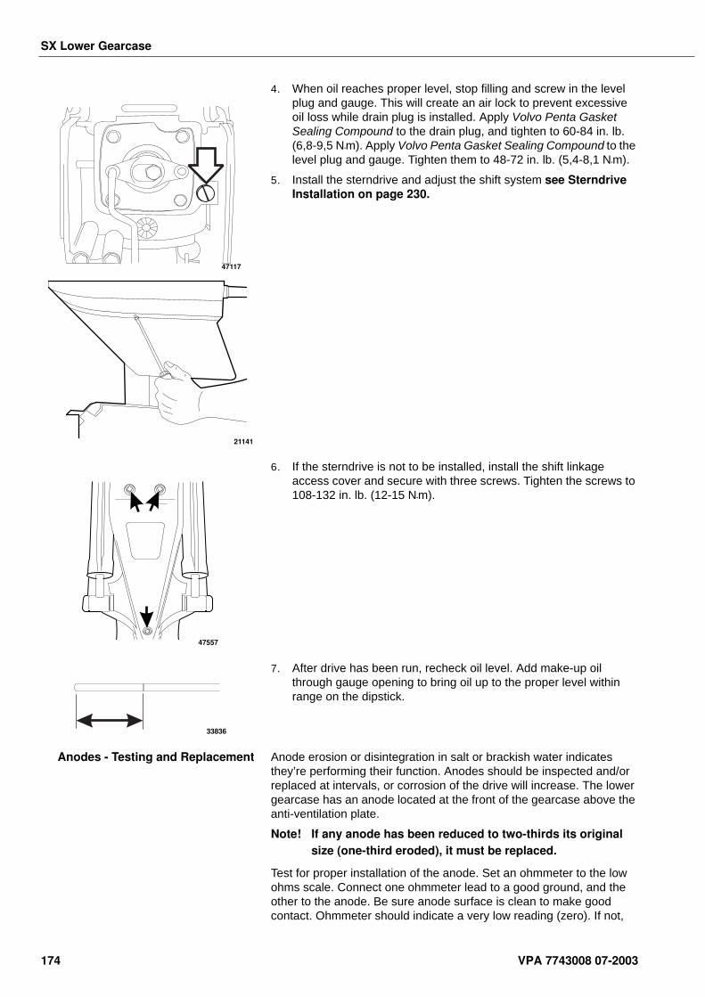
SX Lower Gearcase
4. When oil reaches proper level, stop filling and screw in the level plug and gauge. This will create an air lock to prevent excessive oil loss while drain plug is installed. Apply Volvo Penta Gasket Sealing Compound to the drain plug, and tighten to 60-84 in. lb. (6,8-9,5 N•m). Apply Volvo Penta Gasket Sealing Compound to the level plug and gauge. Tighten them to 48-72 in. lb. (5,4-8,1 N•m).
5. Install the sterndrive and adjust the shift system see Sterndrive Installation on page 230.
6. If the sterndrive is not to be installed, install the shift linkage access cover and secure with three screws. Tighten the screws to 108-132 in. lb. (12-15 N•m).
7. After drive has been run, recheck oil level. Add make-up oil through gauge opening to bring oil up to the proper level within range on the dipstick.
Anodes - Testing and Replacement Anode erosion or disintegration in salt or brackish water indicates they’re performing their function. Anodes should be inspected and/or replaced at intervals, or corrosion of the drive will increase. The lower gearcase has an anode located at the front of the gearcase above the anti-ventilation plate.
Note! If any anode has been reduced to two-thirds its original size (one-third eroded), it must be replaced.
Test for proper installation of the anode. Set an ohmmeter to the low ohms scale. Connect one ohmmeter lead to a good ground, and the other to the anode. Be sure anode surface is clean to make good contact. Ohmmeter should indicate a very low reading (zero). If not,
47117
21141
47557
33836
174 VPA 7743008 07-2003
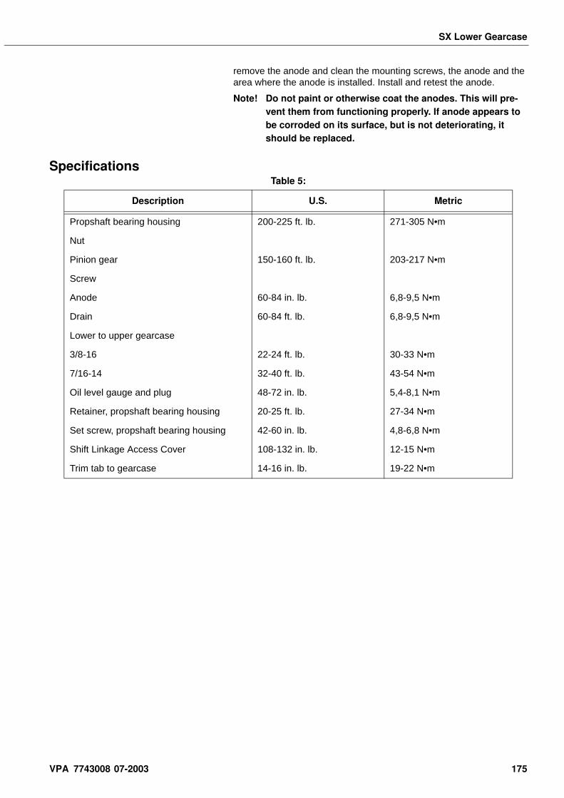
SX Lower Gearcase
remove the anode and clean the mounting screws, the anode and the area where the anode is installed. Install and retest the anode.
Note! Do not paint or otherwise coat the anodes. This will pre-vent them from functioning properly. If anode appears to be corroded on its surface, but is not deteriorating, it should be replaced.
SpecificationsTable 5:
Description U.S. Metric
Propshaft bearing housing 200-225 ft. lb. 271-305 N•m
Nut
Pinion gear 150-160 ft. lb. 203-217 N•m
Screw
Anode 60-84 in. lb. 6,8-9,5 N•m
Drain 60-84 ft. lb. 6,8-9,5 N•m
Lower to upper gearcase
3/8-16 22-24 ft. lb. 30-33 N•m
7/16-14 32-40 ft. lb. 43-54 N•m
Oil level gauge and plug 48-72 in. lb. 5,4-8,1 N•m
Retainer, propshaft bearing housing 20-25 ft. lb. 27-34 N•m
Set screw, propshaft bearing housing 42-60 in. lb. 4,8-6,8 N•m
Shift Linkage Access Cover 108-132 in. lb. 12-15 N•m
Trim tab to gearcase 14-16 in. lb. 19-22 N•m
VPA 7743008 07-2003 175
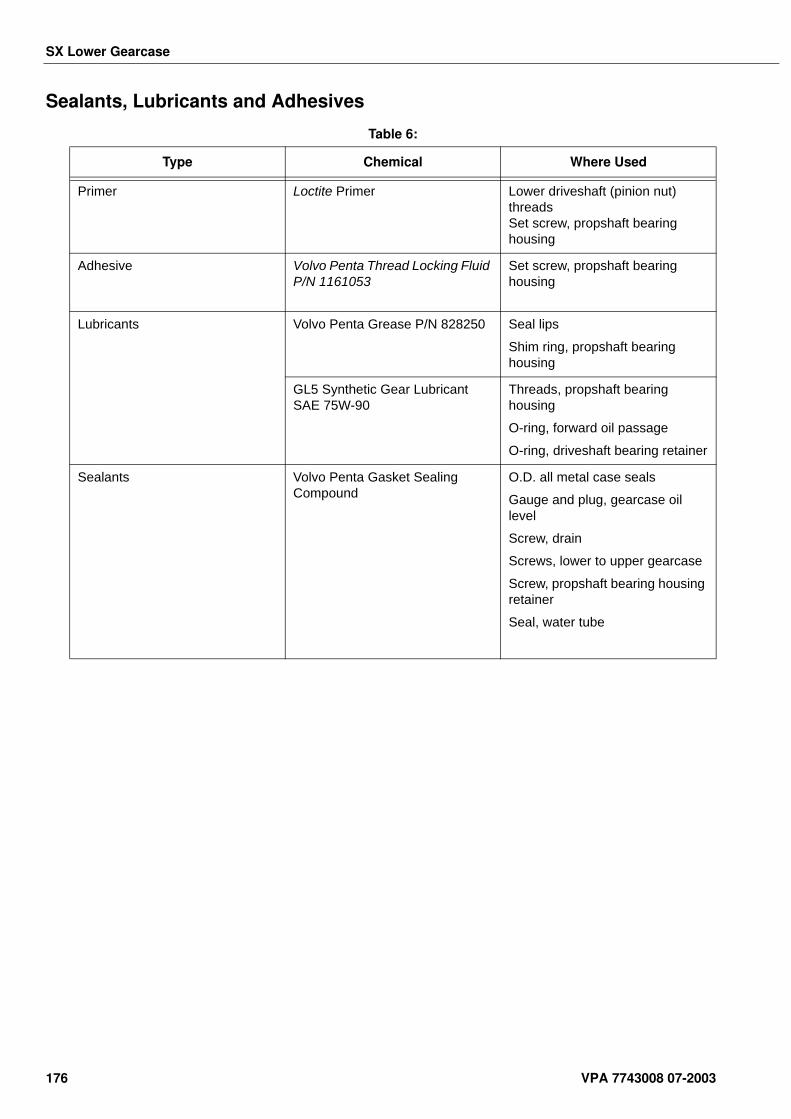
SX Lower Gearcase
Sealants, Lubricants and Adhesives
Table 6:
Type Chemical Where Used
Primer Loctite Primer Lower driveshaft (pinion nut) threadsSet screw, propshaft bearing housing
Adhesive Volvo Penta Thread Locking Fluid P/N 1161053
Set screw, propshaft bearing housing
Lubricants Volvo Penta Grease P/N 828250 Seal lips
Shim ring, propshaft bearing housing
GL5 Synthetic Gear Lubricant SAE 75W-90
Threads, propshaft bearing housing
O-ring, forward oil passage
O-ring, driveshaft bearing retainer
Sealants Volvo Penta Gasket Sealing Compound
O.D. all metal case seals
Gauge and plug, gearcase oil level
Screw, drain
Screws, lower to upper gearcase
Screw, propshaft bearing housing retainer
Seal, water tube
176 VPA 7743008 07-2003
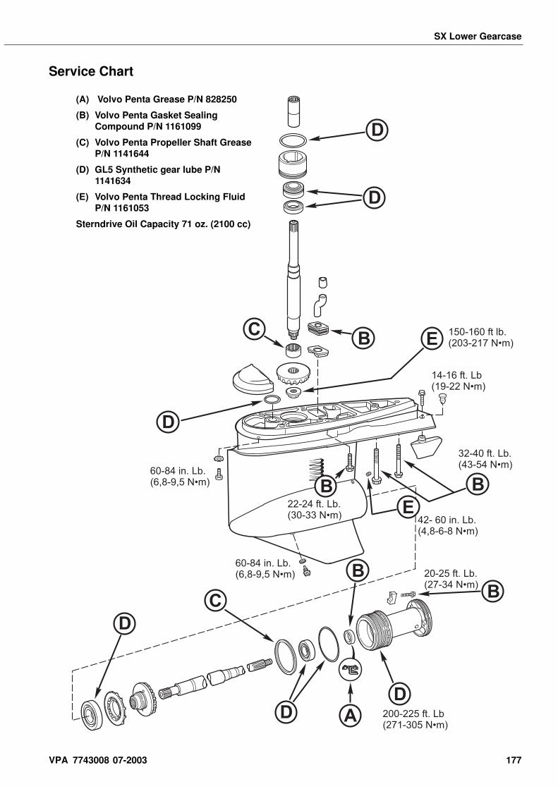
SX Lower Gearcase
C
C
D
D
D
D
D
D
BB
B
A
E
BBE
60-84 in. Lb.(6,8-9,5 N•m)
60-84 in. Lb.(6,8-9,5 N•m)
22-24 ft. Lb.(30-33 N•m)
20-25 ft. Lb.(27-34 N•m)
42- 60 in. Lb.(4,8-6-8 N•m)
32-40 ft. Lb.(43-54 N•m)
14-16 ft. Lb(19-22 N•m)
150-160 ft lb.(203-217 N•m)
200-225 ft. Lb(271-305 N•m)
Service Chart
(A) Volvo Penta Grease P/N 828250
(B) Volvo Penta Gasket Sealing Compound P/N 1161099
(C) Volvo Penta Propeller Shaft Grease P/N 1141644
(D) GL5 Synthetic gear lube P/N 1141634
(E) Volvo Penta Thread Locking Fluid P/N 1161053
Sterndrive Oil Capacity 71 oz. (2100 cc)
VPA 7743008 07-2003 177

Notes . . . . . . . . . . . . . . . . . . . . . . . . . . . . . . . . . . . . . . . . . . . . . . . . . . . . . . . . . . . . . . . . . . . . . . . . . . .
. . . . . . . . . . . . . . . . . . . . . . . . . . . . . . . . . . . . . . . . . . . . . . . . . . . . . . . . . . . . . . . . . . . . . . . . . . .
. . . . . . . . . . . . . . . . . . . . . . . . . . . . . . . . . . . . . . . . . . . . . . . . . . . . . . . . . . . . . . . . . . . . . . . . . . .
. . . . . . . . . . . . . . . . . . . . . . . . . . . . . . . . . . . . . . . . . . . . . . . . . . . . . . . . . . . . . . . . . . . . . . . . . . .
. . . . . . . . . . . . . . . . . . . . . . . . . . . . . . . . . . . . . . . . . . . . . . . . . . . . . . . . . . . . . . . . . . . . . . . . . . .
. . . . . . . . . . . . . . . . . . . . . . . . . . . . . . . . . . . . . . . . . . . . . . . . . . . . . . . . . . . . . . . . . . . . . . . . . . .
. . . . . . . . . . . . . . . . . . . . . . . . . . . . . . . . . . . . . . . . . . . . . . . . . . . . . . . . . . . . . . . . . . . . . . . . . . .
. . . . . . . . . . . . . . . . . . . . . . . . . . . . . . . . . . . . . . . . . . . . . . . . . . . . . . . . . . . . . . . . . . . . . . . . . . .
. . . . . . . . . . . . . . . . . . . . . . . . . . . . . . . . . . . . . . . . . . . . . . . . . . . . . . . . . . . . . . . . . . . . . . . . . . .
. . . . . . . . . . . . . . . . . . . . . . . . . . . . . . . . . . . . . . . . . . . . . . . . . . . . . . . . . . . . . . . . . . . . . . . . . . .
. . . . . . . . . . . . . . . . . . . . . . . . . . . . . . . . . . . . . . . . . . . . . . . . . . . . . . . . . . . . . . . . . . . . . . . . . . .
. . . . . . . . . . . . . . . . . . . . . . . . . . . . . . . . . . . . . . . . . . . . . . . . . . . . . . . . . . . . . . . . . . . . . . . . . . .
. . . . . . . . . . . . . . . . . . . . . . . . . . . . . . . . . . . . . . . . . . . . . . . . . . . . . . . . . . . . . . . . . . . . . . . . . . .
. . . . . . . . . . . . . . . . . . . . . . . . . . . . . . . . . . . . . . . . . . . . . . . . . . . . . . . . . . . . . . . . . . . . . . . . . . .
. . . . . . . . . . . . . . . . . . . . . . . . . . . . . . . . . . . . . . . . . . . . . . . . . . . . . . . . . . . . . . . . . . . . . . . . . . .
. . . . . . . . . . . . . . . . . . . . . . . . . . . . . . . . . . . . . . . . . . . . . . . . . . . . . . . . . . . . . . . . . . . . . . . . . . .
. . . . . . . . . . . . . . . . . . . . . . . . . . . . . . . . . . . . . . . . . . . . . . . . . . . . . . . . . . . . . . . . . . . . . . . . . . .
. . . . . . . . . . . . . . . . . . . . . . . . . . . . . . . . . . . . . . . . . . . . . . . . . . . . . . . . . . . . . . . . . . . . . . . . . . .
. . . . . . . . . . . . . . . . . . . . . . . . . . . . . . . . . . . . . . . . . . . . . . . . . . . . . . . . . . . . . . . . . . . . . . . . . . .
. . . . . . . . . . . . . . . . . . . . . . . . . . . . . . . . . . . . . . . . . . . . . . . . . . . . . . . . . . . . . . . . . . . . . . . . . . .
. . . . . . . . . . . . . . . . . . . . . . . . . . . . . . . . . . . . . . . . . . . . . . . . . . . . . . . . . . . . . . . . . . . . . . . . . . .
. . . . . . . . . . . . . . . . . . . . . . . . . . . . . . . . . . . . . . . . . . . . . . . . . . . . . . . . . . . . . . . . . . . . . . . . . . .
. . . . . . . . . . . . . . . . . . . . . . . . . . . . . . . . . . . . . . . . . . . . . . . . . . . . . . . . . . . . . . . . . . . . . . . . . . .
. . . . . . . . . . . . . . . . . . . . . . . . . . . . . . . . . . . . . . . . . . . . . . . . . . . . . . . . . . . . . . . . . . . . . . . . . . .
. . . . . . . . . . . . . . . . . . . . . . . . . . . . . . . . . . . . . . . . . . . . . . . . . . . . . . . . . . . . . . . . . . . . . . . . . . .
. . . . . . . . . . . . . . . . . . . . . . . . . . . . . . . . . . . . . . . . . . . . . . . . . . . . . . . . . . . . . . . . . . . . . . . . . . .
. . . . . . . . . . . . . . . . . . . . . . . . . . . . . . . . . . . . . . . . . . . . . . . . . . . . . . . . . . . . . . . . . . . . . . . . . . .
. . . . . . . . . . . . . . . . . . . . . . . . . . . . . . . . . . . . . . . . . . . . . . . . . . . . . . . . . . . . . . . . . . . . . . . . . . .
. . . . . . . . . . . . . . . . . . . . . . . . . . . . . . . . . . . . . . . . . . . . . . . . . . . . . . . . . . . . . . . . . . . . . . . . . . .
. . . . . . . . . . . . . . . . . . . . . . . . . . . . . . . . . . . . . . . . . . . . . . . . . . . . . . . . . . . . . . . . . . . . . . . . . . .
. . . . . . . . . . . . . . . . . . . . . . . . . . . . . . . . . . . . . . . . . . . . . . . . . . . . . . . . . . . . . . . . . . . . . . . . . . .
. . . . . . . . . . . . . . . . . . . . . . . . . . . . . . . . . . . . . . . . . . . . . . . . . . . . . . . . . . . . . . . . . . . . . . . . . . .
. . . . . . . . . . . . . . . . . . . . . . . . . . . . . . . . . . . . . . . . . . . . . . . . . . . . . . . . . . . . . . . . . . . . . . . . . . .
178 VPA 7743008 07-2003
DP-S Lower Gearcase
DP-S Lower GearcaseTable of Contents Gearcase Retaining Plate . . . . . . . . . . . . . . . . . . . . . . . . . . . 186
Special Tools . . . . . . . . . . . . . . . . . . . . . . . . . . . . . . 187Propeller Shaft Runout . . . . . . . . . . . . . . . . . . . . . . . . . . . . . 189
Lower Gearcase Removal . . . . . . . . . . . . . . . . . . . . 189Lower Gearease Disassembly . . . . . . . . . . . . . . . . . 191
Propeller Shaft Housing Propeller Shaft Removal . . . . . . 191Inner Propeller Shaft Removal . . . . . . . . . . . . . . . . . . . . . . 192Water Tube Guide and Anode Removal . . . . . . . . . . . . . . . 193Driveshaft and Pinion Removal . . . . . . . . . . . . . . . . . . . . . . 194Gearease Bearing and Race Removal . . . . . . . . . . . . . . . . 195Lower Driveshaft Bearing . . . . . . . . . . . . . . . . . . . . . . . . . . 195Pinion Bearing . . . . . . . . . . . . . . . . . . . . . . . . . . . . . . . . . . . 195Forward Bearing Race . . . . . . . . . . . . . . . . . . . . . . . . . . . . . 196
Propeller Shaft Housing Service . . . . . . . . . . . . . . . 196Outer Propeller Shaft Service . . . . . . . . . . . . . . . . . 198
Forward Gear Service . . . . . . . . . . . . . . . . . . . . . . . . . . . . . . 201Driveshaft Service . . . . . . . . . . . . . . . . . . . . . . . . . . . . . . . . 202Magnet Service . . . . . . . . . . . . . . . . . . . . . . . . . . . . . . . . . . . 203Upper Housing Stud Replacement . . . . . . . . . . . . . . . . . . . 204Pinion Shimming . . . . . . . . . . . . . . . . . . . . . . . . . . . . . . . . . 204Forward Gear Shimming . . . . . . . . . . . . . . . . . . . . . . . . . . . 205Outer Propeller Shaft Shimming . . . . . . . . . . . . . . . . . . . . . 207Oil Screen Service - Upper Housing . . . . . . . . . . . . . . . . . . 211Exhaust Cover Service . . . . . . . . . . . . . . . . . . . . . . . . . . . . . 211
Lower Gearcase Assembly . . . . . . . . . . . . . . . . . . . 212Gearease Bearing and Race Installation . . . . . . . . . . . . . . 212Forward Bearing Race . . . . . . . . . . . . . . . . . . . . . . . . . . . . . 212Pinion Bearing . . . . . . . . . . . . . . . . . . . . . . . . . . . . . . . . . . . 212Lower Driveshaft Bearing . . . . . . . . . . . . . . . . . . . . . . . . . . 213Driveshaft and Pinion Installation . . . . . . . . . . . . . . . . . . . . 214Setting Initial Rolling Torque . . . . . . . . . . . . . . . . . . . . . . . . 215Propeller Shaft Housing and Propeller Shaft Installation . 216Setting Final Rolling Torque . . . . . . . . . . . . . . . . . . . . . . . . 219Checking Tooth Contact Pattern . . . . . . . . . . . . . . . . . . . . . 221Adjusting Tooth Contact Pattern and Gear Lash . . . . . . . 222
Final Assembly . . . . . . . . . . . . . . . . . . . . . . . . . . . . . 223Lower Gearcase Installation . . . . . . . . . . . . . . . . . . 224
Pressure and Vacuum Testing . . . . . . . . . . . . . . . . . . . . . . 226Sterndrive Filling . . . . . . . . . . . . . . . . . . . . . . . . . . . . . . . . . 227Anode - Testing and Replacement . . . . . . . . . . . . . . . . . . . 229
Specifications . . . . . . . . . . . . . . . . . . . . . . . . . . . . . . 230Sealants, Lubricants and Adhesives . . . . . . . . . . . 231Service Chart . . . . . . . . . . . . . . . . . . . . . . . . . . . . . . . 32
Safety Warnings Before working on any part of the lower gearcase, read the section called Safety at the end of this manual. Several of the following procedures require the use of an arbor or hydraulic press. Always wear safety glasses when using this device to perform these procedures.
VPA 7743008 07-2003 179
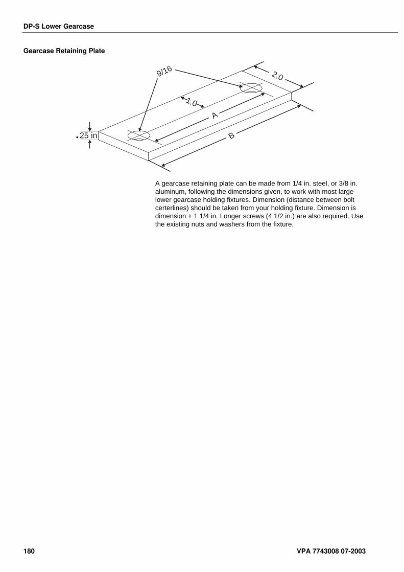
DP-S Lower Gearcase
Gearcase Retaining Plate
A gearcase retaining plate can be made from 1/4 in. steel, or 3/8 in. aluminum, following the dimensions given, to work with most large lower gearcase holding fixtures. Dimension (distance between bolt certerlines) should be taken from your holding fixture. Dimension is dimension + 1 1/4 in. Longer screws (4 1/2 in.) are also required. Use the existing nuts and washers from the fixture.
25 in
2.09/16
1.0
B
A
180 VPA 7743008 07-2003
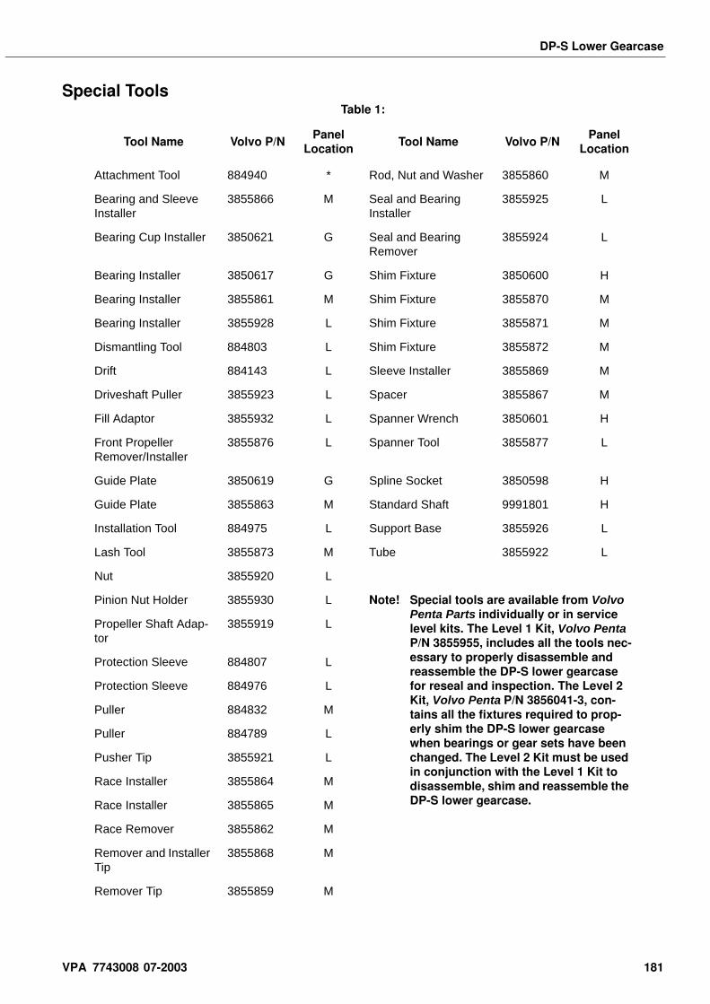
DP-S Lower Gearcase
Special ToolsTable 1:
Tool Name Volvo P/NPanel
LocationTool Name Volvo P/N
Panel Location
Attachment Tool 884940 * Rod, Nut and Washer 3855860 M
Bearing and Sleeve Installer
3855866 M Seal and Bearing Installer
3855925 L
Bearing Cup Installer 3850621 G Seal and Bearing Remover
3855924 L
Bearing Installer 3850617 G Shim Fixture 3850600 H
Bearing Installer 3855861 M Shim Fixture 3855870 M
Bearing Installer 3855928 L Shim Fixture 3855871 M
Dismantling Tool 884803 L Shim Fixture 3855872 M
Drift 884143 L Sleeve Installer 3855869 M
Driveshaft Puller 3855923 L Spacer 3855867 M
Fill Adaptor 3855932 L Spanner Wrench 3850601 H
Front Propeller Remover/Installer
3855876 L Spanner Tool 3855877 L
Guide Plate 3850619 G Spline Socket 3850598 H
Guide Plate 3855863 M Standard Shaft 9991801 H
Installation Tool 884975 L Support Base 3855926 L
Lash Tool 3855873 M Tube 3855922 L
Nut 3855920 L
Pinion Nut Holder 3855930 L Note! Special tools are available from Volvo Penta Parts individually or in service level kits. The Level 1 Kit, Volvo Penta P/N 3855955, includes all the tools nec-essary to properly disassemble and reassemble the DP-S lower gearcase for reseal and inspection. The Level 2 Kit, Volvo Penta P/N 3856041-3, con-tains all the fixtures required to prop-erly shim the DP-S lower gearcase when bearings or gear sets have been changed. The Level 2 Kit must be used in conjunction with the Level 1 Kit to disassemble, shim and reassemble the DP-S lower gearcase.
Propeller Shaft Adap-tor
3855919 L
Protection Sleeve 884807 L
Protection Sleeve 884976 L
Puller 884832 M
Puller 884789 L
Pusher Tip 3855921 L
Race Installer 3855864 M
Race Installer 3855865 M
Race Remover 3855862 M
Remover and Installer Tip
3855868 M
Remover Tip 3855859 M
VPA 7743008 07-2003 181
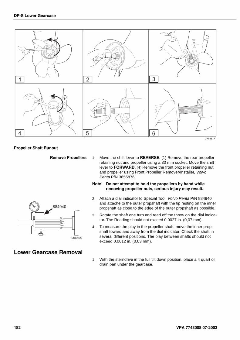
DP-S Lower Gearcase
Propeller Shaft Runout
Remove Propellers 1. Move the shift lever to REVERSE. (1) Remove the rear propeller retaining nut and propeller using a 30 mm socket. Move the shift lever to FORWARD. (4) Remove the front propeller retaining nut and propeller using Front Propeller Remover/Installer, Volvo Penta P/N 3855876.
Note! Do not attempt to hold the propellers by hand while removing propeller nuts, serious injury may result.
2. Attach a dial indicator to Special Tool, Volvo Penta P/N 884940 and attache to the outer propshaft with the tip resting on the inner propshaft as close to the edge of the outer propshaft as possible.
3. Rotate the shaft one turn and read off the throw on the dial indica-tor. The Reading should not exceed 0.0027 in. (0,07 mm).
4. To measure the play in the propeller shaft, move the inner prop-shaft toward and away from the dial indicator. Check the shaft in several different positions. The play between shafts should not exceed 0.0012 in. (0,03 mm).
Lower Gearcase Removal1. With the sterndrive in the full tilt down position, place a 4 quart oil
drain pan under the gearcase.
VOLVO PENTA
654
VOLVOPENTA
DUOPROP
31 2
DR5387A
884940
DRC7429
182 VPA 7743008 07-2003
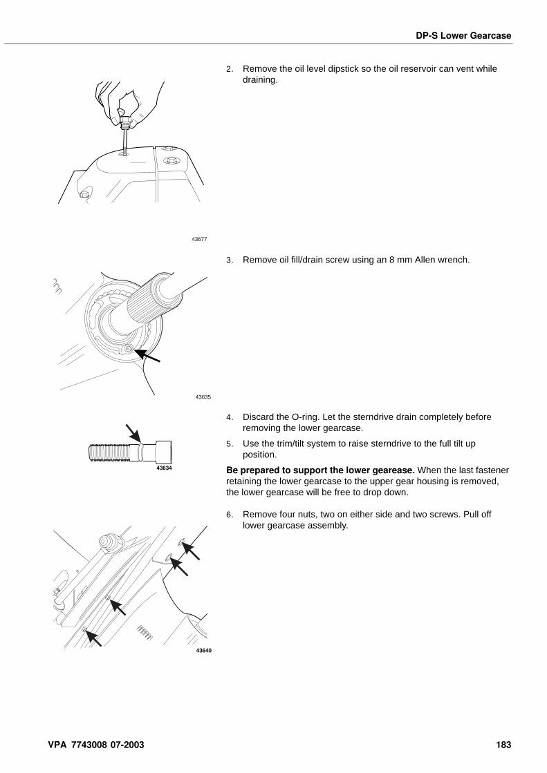
DP-S Lower Gearcase
2. Remove the oil level dipstick so the oil reservoir can vent while draining.
3. Remove oil fill/drain screw using an 8 mm Allen wrench.
4. Discard the O-ring. Let the sterndrive drain completely before removing the lower gearcase.
5. Use the trim/tilt system to raise sterndrive to the full tilt up position.
Be prepared to support the lower gearease. When the last fastener retaining the lower gearcase to the upper gear housing is removed, the lower gearcase will be free to drop down.
6. Remove four nuts, two on either side and two screws. Pull off lower gearcase assembly.
43677
43635
43634
43640
VPA 7743008 07-2003 183
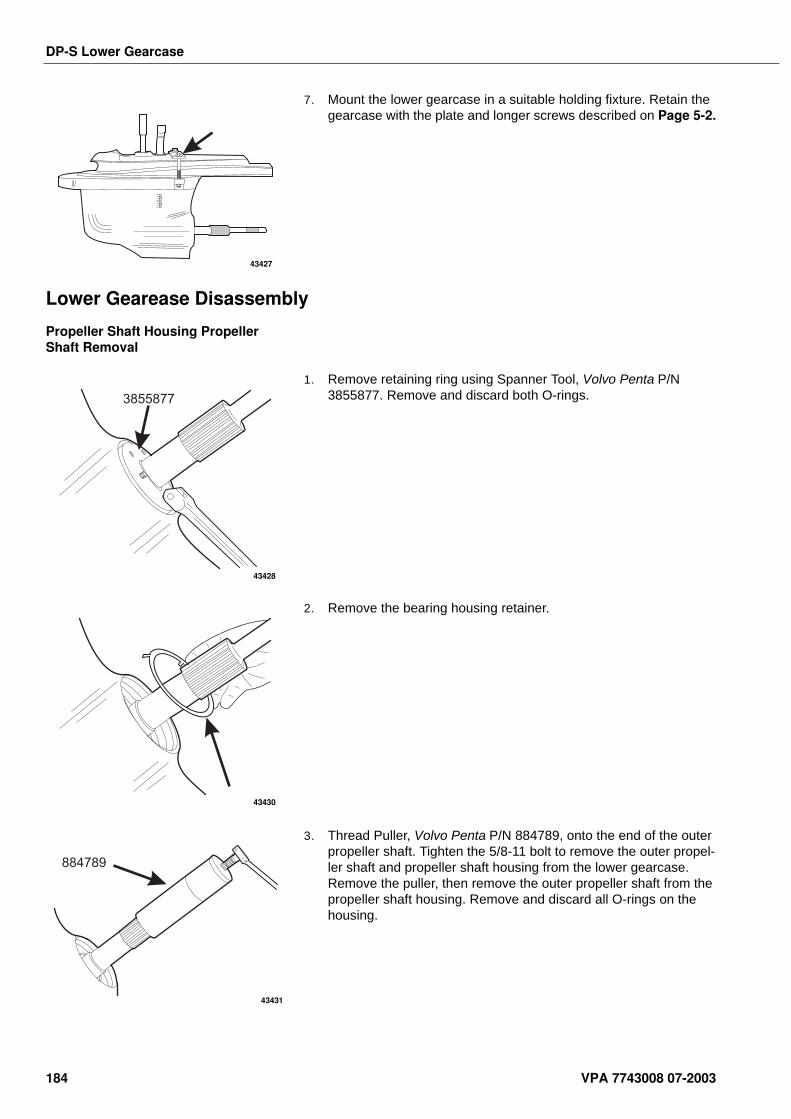
DP-S Lower Gearcase
7. Mount the lower gearcase in a suitable holding fixture. Retain the gearcase with the plate and longer screws described on Page 5-2.
Lower Gearease Disassembly
Propeller Shaft Housing Propeller Shaft Removal
1. Remove retaining ring using Spanner Tool, Volvo Penta P/N 3855877. Remove and discard both O-rings.
2. Remove the bearing housing retainer.
3. Thread Puller, Volvo Penta P/N 884789, onto the end of the outer propeller shaft. Tighten the 5/8-11 bolt to remove the outer propel-ler shaft and propeller shaft housing from the lower gearcase. Remove the puller, then remove the outer propeller shaft from the propeller shaft housing. Remove and discard all O-rings on the housing.
43427
3855877
43428
43430
884789
43431
184 VPA 7743008 07-2003
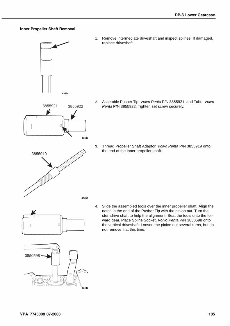
DP-S Lower Gearcase
Inner Propeller Shaft Removal
1. Remove intermediate driveshaft and inspect splines. If damaged, replace driveshaft.
2. Assemble Pusher Tip, Volvo Penta P/N 3855921, and Tube, Volvo Penta P/N 3855922. Tighten set screw securely.
3. Thread Propeller Shaft Adaptor, Volvo Penta P/N 3855919 onto the end of the inner propeller shaft.
4. Slide the assembled tools over the inner propeller shaft. Align the notch in the end of the Pusher Tip with the pinion nut. Turn the sterndrive shaft to help the alignment. Seat the tools onto the for-ward gear. Place Spline Socket, Volvo Penta P/N 3850598 onto the vertical driveshaft. Loosen the pinion nut several turns, but do not remove it at this time.
43674
3855921 3855922
43432
3855919
43433
3850598
43436
VPA 7743008 07-2003 185
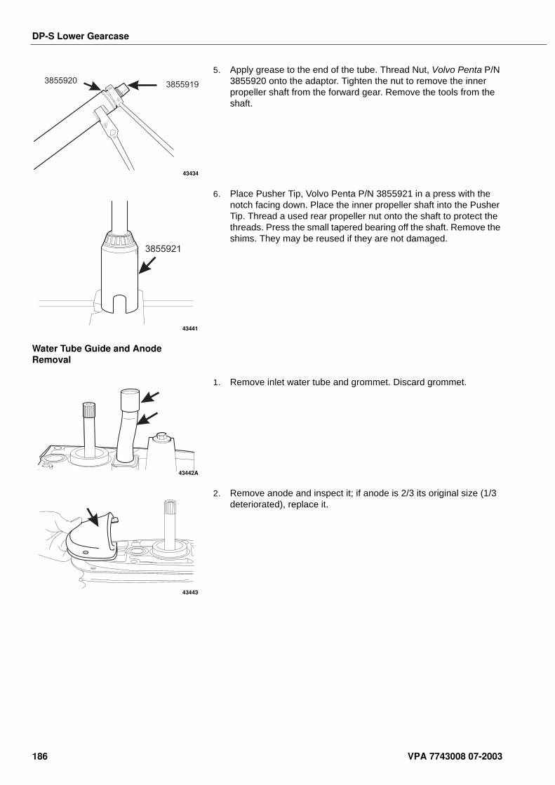
DP-S Lower Gearcase
5. Apply grease to the end of the tube. Thread Nut, Volvo Penta P/N 3855920 onto the adaptor. Tighten the nut to remove the inner propeller shaft from the forward gear. Remove the tools from the shaft.
6. Place Pusher Tip, Volvo Penta P/N 3855921 in a press with the notch facing down. Place the inner propeller shaft into the Pusher Tip. Thread a used rear propeller nut onto the shaft to protect the threads. Press the small tapered bearing off the shaft. Remove the shims. They may be reused if they are not damaged.
Water Tube Guide and Anode Removal
1. Remove inlet water tube and grommet. Discard grommet.
2. Remove anode and inspect it; if anode is 2/3 its original size (1/3 deteriorated), replace it.
38559193855920
43434
3855921
43441
43442A
43443
186 VPA 7743008 07-2003
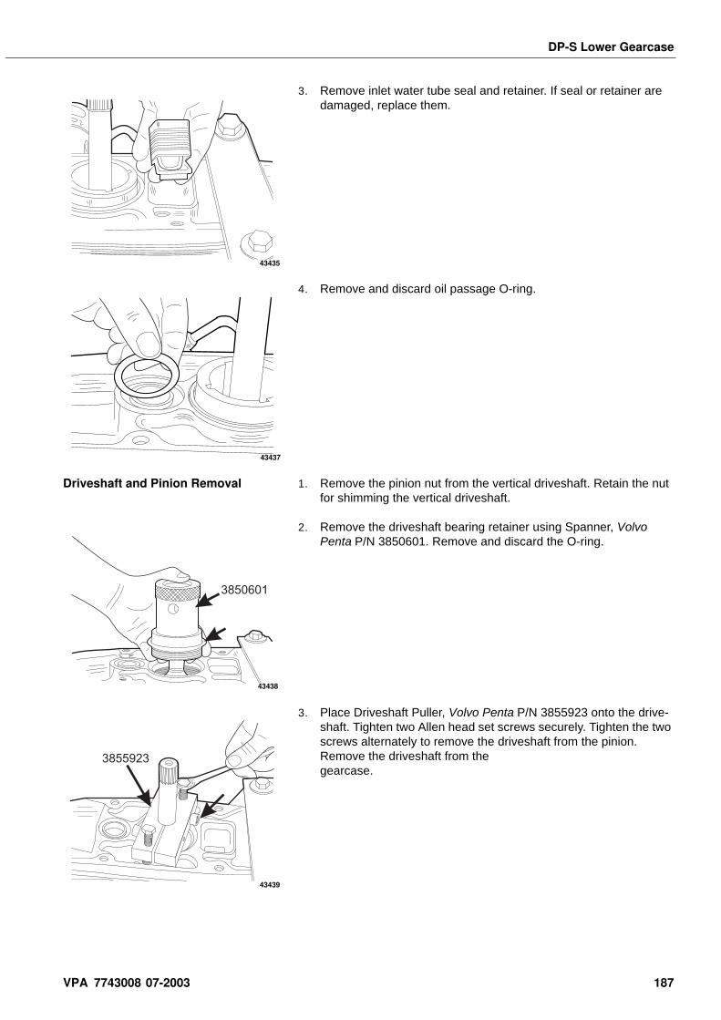
DP-S Lower Gearcase
3. Remove inlet water tube seal and retainer. If seal or retainer are damaged, replace them.
4. Remove and discard oil passage O-ring.
Driveshaft and Pinion Removal 1. Remove the pinion nut from the vertical driveshaft. Retain the nut for shimming the vertical driveshaft.
2. Remove the driveshaft bearing retainer using Spanner, Volvo Penta P/N 3850601. Remove and discard the O-ring.
3. Place Driveshaft Puller, Volvo Penta P/N 3855923 onto the drive-shaft. Tighten two Allen head set screws securely. Tighten the two screws alternately to remove the driveshaft from the pinion. Remove the driveshaft from the gearcase.
43435
43437
3850601
43438
3855923
43439
VPA 7743008 07-2003 187
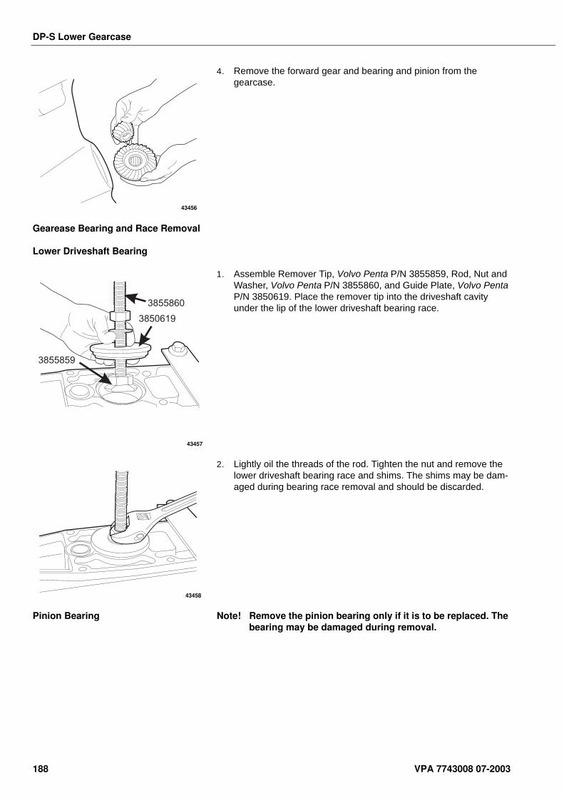
DP-S Lower Gearcase
4. Remove the forward gear and bearing and pinion from the gearcase.
Gearease Bearing and Race Removal
Lower Driveshaft Bearing
1. Assemble Remover Tip, Volvo Penta P/N 3855859, Rod, Nut and Washer, Volvo Penta P/N 3855860, and Guide Plate, Volvo Penta P/N 3850619. Place the remover tip into the driveshaft cavity under the lip of the lower driveshaft bearing race.
2. Lightly oil the threads of the rod. Tighten the nut and remove the lower driveshaft bearing race and shims. The shims may be dam-aged during bearing race removal and should be discarded.
Pinion Bearing Note! Remove the pinion bearing only if it is to be replaced. The bearing may be damaged during removal.
43456
3855859
3850619
3855860
43457
43458
188 VPA 7743008 07-2003
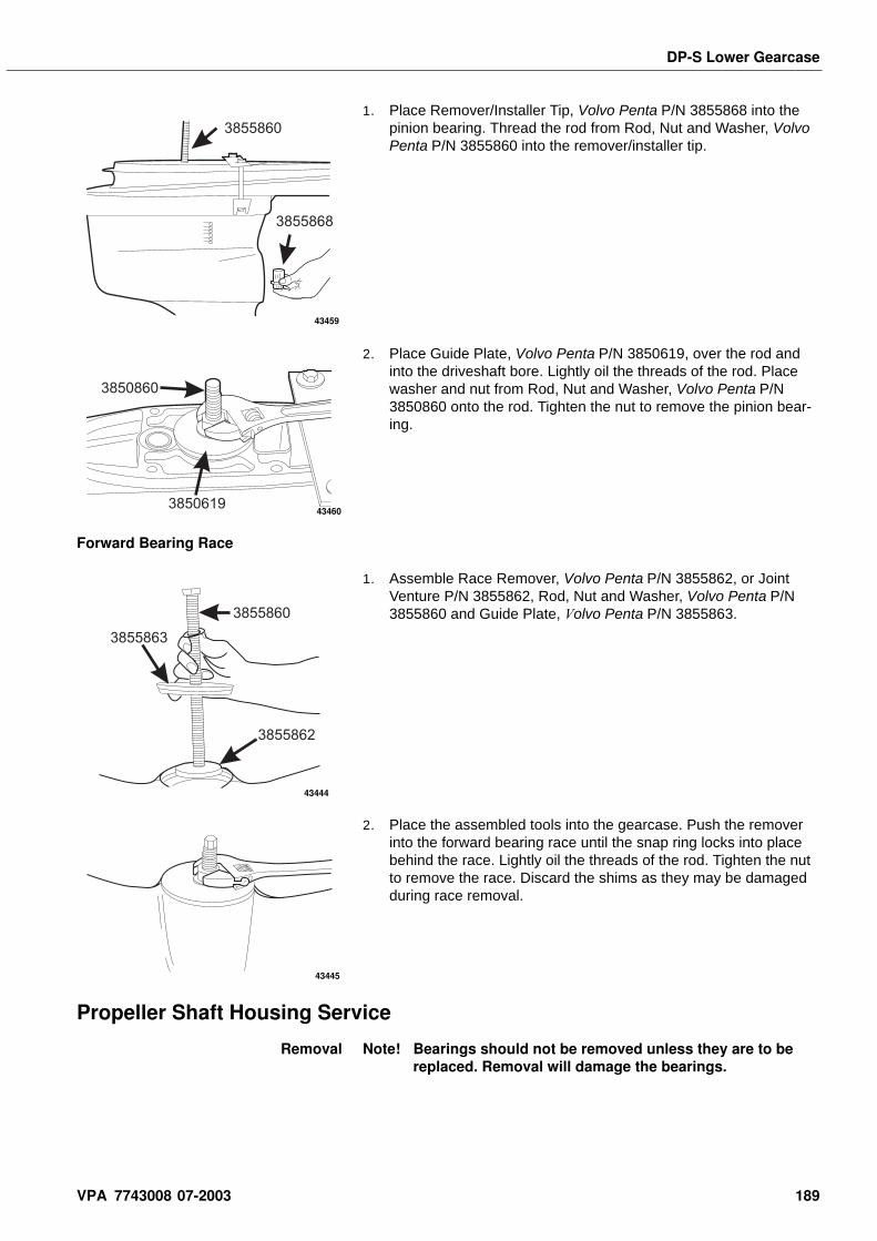
DP-S Lower Gearcase
1. Place Remover/Installer Tip, Volvo Penta P/N 3855868 into the pinion bearing. Thread the rod from Rod, Nut and Washer, Volvo Penta P/N 3855860 into the remover/installer tip.
2. Place Guide Plate, Volvo Penta P/N 3850619, over the rod and into the driveshaft bore. Lightly oil the threads of the rod. Place washer and nut from Rod, Nut and Washer, Volvo Penta P/N 3850860 onto the rod. Tighten the nut to remove the pinion bear-ing.
Forward Bearing Race
1. Assemble Race Remover, Volvo Penta P/N 3855862, or Joint Venture P/N 3855862, Rod, Nut and Washer, Volvo Penta P/N 3855860 and Guide Plate, Volvo Penta P/N 3855863.
2. Place the assembled tools into the gearcase. Push the remover into the forward bearing race until the snap ring locks into place behind the race. Lightly oil the threads of the rod. Tighten the nut to remove the race. Discard the shims as they may be damaged during race removal.
Propeller Shaft Housing Service
Removal Note! Bearings should not be removed unless they are to be replaced. Removal will damage the bearings.
3855868
3855860
43459
3850619
3850860
43460
3855862
3855860
3855863
43444
43445
VPA 7743008 07-2003 189
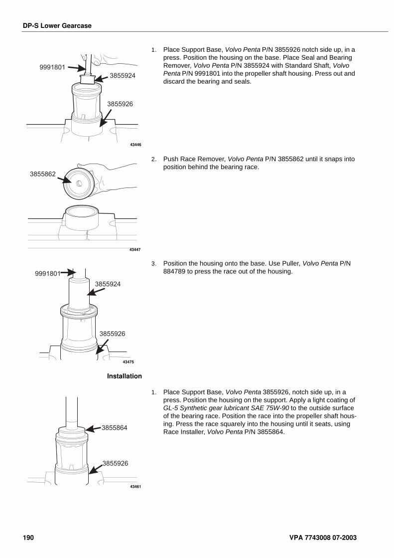
DP-S Lower Gearcase
1. Place Support Base, Volvo Penta P/N 3855926 notch side up, in a press. Position the housing on the base. Place Seal and Bearing Remover, Volvo Penta P/N 3855924 with Standard Shaft, Volvo Penta P/N 9991801 into the propeller shaft housing. Press out and discard the bearing and seals.
2. Push Race Remover, Volvo Penta P/N 3855862 until it snaps into position behind the bearing race.
3. Position the housing onto the base. Use Puller, Volvo Penta P/N 884789 to press the race out of the housing.
Installation
1. Place Support Base, Volvo Penta 3855926, notch side up, in a press. Position the housing on the support. Apply a light coating of GL-5 Synthetic gear lubricant SAE 75W-90 to the outside surface of the bearing race. Position the race into the propeller shaft hous-ing. Press the race squarely into the housing until it seats, using Race Installer, Volvo Penta P/N 3855864.
3855926
3855924
9991801
43446
3855862
43447
3855926
3855924
9991801
43475
3855926
3855864
43461
190 VPA 7743008 07-2003
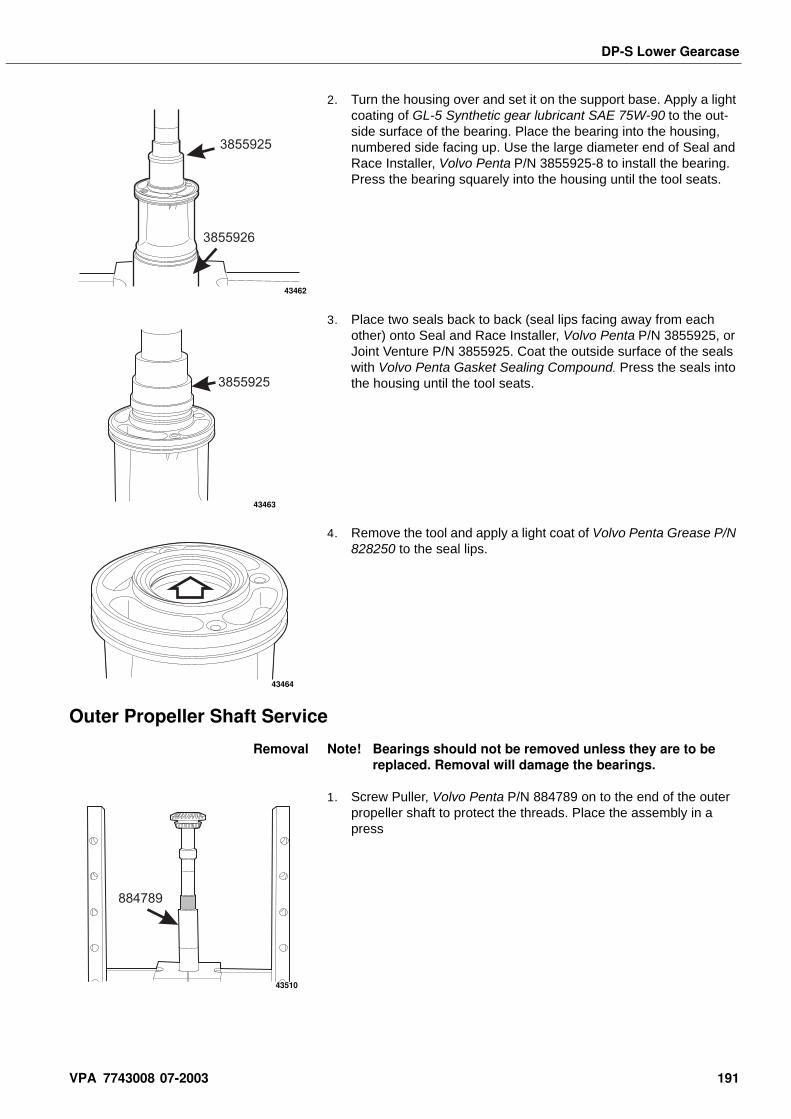
DP-S Lower Gearcase
2. Turn the housing over and set it on the support base. Apply a light coating of GL-5 Synthetic gear lubricant SAE 75W-90 to the out-side surface of the bearing. Place the bearing into the housing, numbered side facing up. Use the large diameter end of Seal and Race Installer, Volvo Penta P/N 3855925-8 to install the bearing. Press the bearing squarely into the housing until the tool seats.
3. Place two seals back to back (seal lips facing away from each other) onto Seal and Race Installer, Volvo Penta P/N 3855925, or Joint Venture P/N 3855925. Coat the outside surface of the seals with Volvo Penta Gasket Sealing Compound. Press the seals into the housing until the tool seats.
4. Remove the tool and apply a light coat of Volvo Penta Grease P/N 828250 to the seal lips.
Outer Propeller Shaft Service
Removal Note! Bearings should not be removed unless they are to be replaced. Removal will damage the bearings.
1. Screw Puller, Volvo Penta P/N 884789 on to the end of the outer propeller shaft to protect the threads. Place the assembly in a press
3855926
3855925
43462
3855925
43463
43464
884789
43510
VPA 7743008 07-2003 191
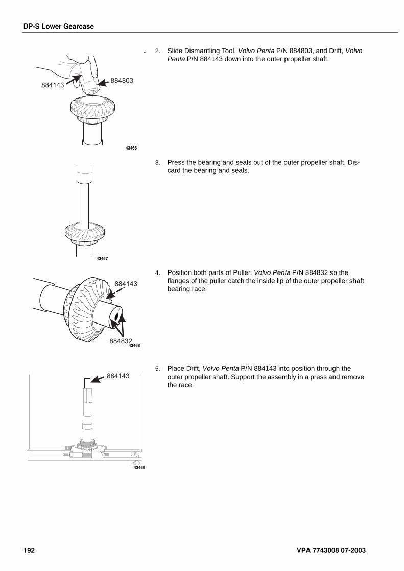
DP-S Lower Gearcase
. 2. Slide Dismantling Tool, Volvo Penta P/N 884803, and Drift, Volvo Penta P/N 884143 down into the outer propeller shaft.
3. Press the bearing and seals out of the outer propeller shaft. Dis-card the bearing and seals.
4. Position both parts of Puller, Volvo Penta P/N 884832 so the flanges of the puller catch the inside lip of the outer propeller shaft bearing race.
5. Place Drift, Volvo Penta P/N 884143 into position through the outer propeller shaft. Support the assembly in a press and remove the race.
884803884143
43466
43467
884832
884143
43468
884143
43469
192 VPA 7743008 07-2003
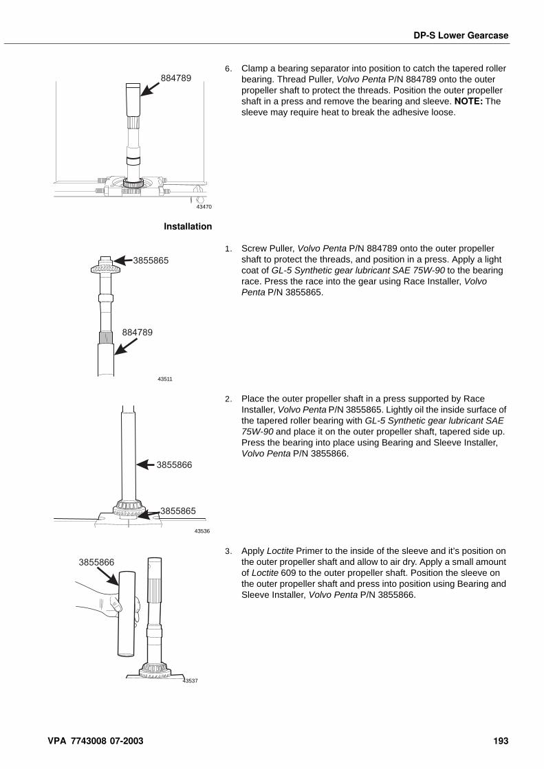
DP-S Lower Gearcase
6. Clamp a bearing separator into position to catch the tapered roller bearing. Thread Puller, Volvo Penta P/N 884789 onto the outer propeller shaft to protect the threads. Position the outer propeller shaft in a press and remove the bearing and sleeve. NOTE: The sleeve may require heat to break the adhesive loose.
Installation
1. Screw Puller, Volvo Penta P/N 884789 onto the outer propeller shaft to protect the threads, and position in a press. Apply a light coat of GL-5 Synthetic gear lubricant SAE 75W-90 to the bearing race. Press the race into the gear using Race Installer, Volvo Penta P/N 3855865.
2. Place the outer propeller shaft in a press supported by Race Installer, Volvo Penta P/N 3855865. Lightly oil the inside surface of the tapered roller bearing with GL-5 Synthetic gear lubricant SAE 75W-90 and place it on the outer propeller shaft, tapered side up. Press the bearing into place using Bearing and Sleeve Installer, Volvo Penta P/N 3855866.
3. Apply Loctite Primer to the inside of the sleeve and it’s position on the outer propeller shaft and allow to air dry. Apply a small amount of Loctite 609 to the outer propeller shaft. Position the sleeve on the outer propeller shaft and press into position using Bearing and Sleeve Installer, Volvo Penta P/N 3855866.
884789
43470
884789
3855865
43511
3855865
3855866
43536
3855866
43537
VPA 7743008 07-2003 193
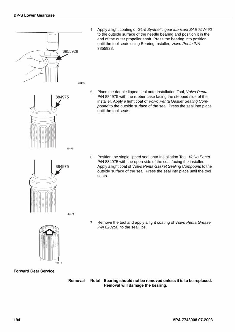
DP-S Lower Gearcase
4. Apply a light coating of GL-5 Synthetic gear lubricant SAE 75W-90 to the outside surface of the needle bearing and position it in the end of the outer propeller shaft. Press the bearing into position until the tool seats using Bearing Installer, Volvo Penta P/N 3855928.
5. Place the double lipped seal onto Installation Tool, Volvo Penta P/N 884975 with the rubber case facing the stepped side of the installer. Apply a light coat of Volvo Penta Gasket Sealing Com-pound to the outside surface of the seal. Press the seal into place until the tool seats.
6. Position the single lipped seal onto Installation Tool, Volvo Penta P/N 884975 with the open side of the seal facing the installer. Apply a light coat of Volvo Penta Gasket Sealing Compound to the outside surface of the seal. Press the seal into place until the tool seats.
7. Remove the tool and apply a light coating of Volvo Penta Grease P/N 828250 to the seal lips.
Forward Gear Service
Removal Note! Bearing should not be removed unless it is to be replaced. Removal will damage the bearing.
3855928
43485
884975
43473
884975
43474
43676
194 VPA 7743008 07-2003
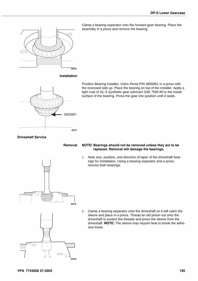
DP-S Lower Gearcase
Clamp a bearing separator onto the forward gear bearing. Place the assembly in a press and remove the bearing.
Installation
Position Bearing Installer, Volvo Penta P/N 3855861 in a press with the recessed side up. Place the bearing on top of the installer. Apply a light coat of GL-5 Synthetic gear lubricant SAE 75W-90 to the inside surface of the bearing. Press the gear into position until it seats.
Driveshaft Service
Removal NOTE! Bearings should not be removed unless they are to be replaced. Removal will damage the bearings.
1. Note size, position, and direction of taper of the driveshaft bear-ings for installation. Using a bearing separator and a press, remove both bearings.
2. Clamp a bearing separator onto the driveshaft so it will catch the sleeve and place in a press. Thread an old pinion nut onto the driveshaft to protect the threads and press the sleeve from the driveshaft. NOTE: The sleeve may require heat to break the adhe-sive loose.
43476
3855861
43477
43478
43479
VPA 7743008 07-2003 195
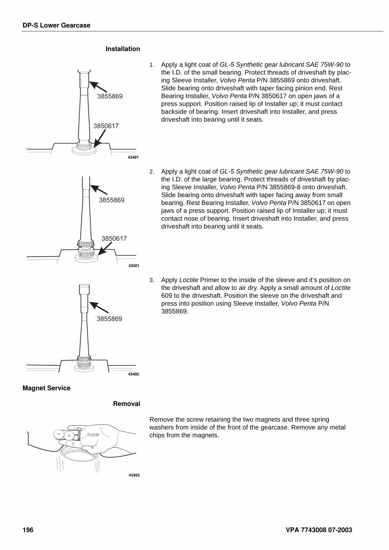
DP-S Lower Gearcase
Installation
1. Apply a light coat of GL-5 Synthetic gear lubricant SAE 75W-90 to the I.D. of the small bearing. Protect threads of driveshaft by plac-ing Sleeve Installer, Volvo Penta P/N 3855869 onto driveshaft. Slide bearing onto driveshaft with taper facing pinion end. Rest Bearing Installer, Volvo Penta P/N 3850617 on open jaws of a press support. Position raised lip of Installer up; it must contact backside of bearing. Insert driveshaft into Installer, and press driveshaft into bearing until it seats.
2. Apply a light coat of GL-5 Synthetic gear lubricant SAE 75W-90 to the I.D. of the large bearing. Protect threads of driveshaft by plac-ing Sleeve Installer, Volvo Penta P/N 3855869-8 onto driveshaft. Slide bearing onto driveshaft with taper facing away from small bearing. Rest Bearing Installer, Volvo Penta P/N 3850617 on open jaws of a press support. Position raised lip of Installer up; it must contact nose of bearing. Insert driveshaft into Installer, and press driveshaft into bearing until it seats.
3. Apply Loctite Primer to the inside of the sleeve and it’s position on the driveshaft and allow to air dry. Apply a small amount of Loctite 609 to the driveshaft. Position the sleeve on the driveshaft and press into position using Sleeve Installer, Volvo Penta P/N 3855869.
Magnet Service
Removal
Remove the screw retaining the two magnets and three spring washers from inside of the front of the gearcase. Remove any metal chips from the magnets.
3855869
3850617
43481
3855869
3850617
43501
3855869
43492
43493
196 VPA 7743008 07-2003
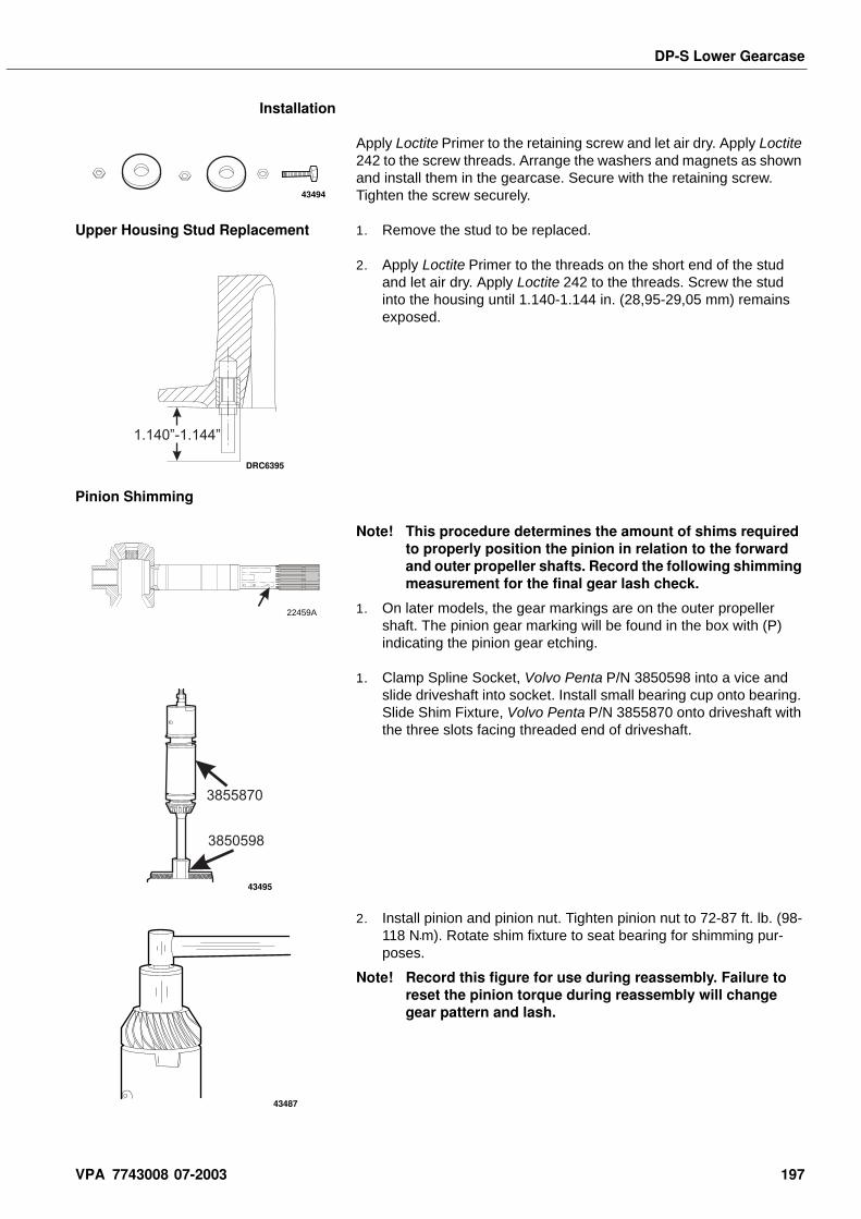
DP-S Lower Gearcase
Installation
Apply Loctite Primer to the retaining screw and let air dry. Apply Loctite 242 to the screw threads. Arrange the washers and magnets as shown and install them in the gearcase. Secure with the retaining screw. Tighten the screw securely.
Upper Housing Stud Replacement 1. Remove the stud to be replaced.
2. Apply Loctite Primer to the threads on the short end of the stud and let air dry. Apply Loctite 242 to the threads. Screw the stud into the housing until 1.140-1.144 in. (28,95-29,05 mm) remains exposed.
Pinion Shimming
Note! This procedure determines the amount of shims required to properly position the pinion in relation to the forward and outer propeller shafts. Record the following shimming measurement for the final gear lash check.
1. On later models, the gear markings are on the outer propeller shaft. The pinion gear marking will be found in the box with (P) indicating the pinion gear etching.
1. Clamp Spline Socket, Volvo Penta P/N 3850598 into a vice and slide driveshaft into socket. Install small bearing cup onto bearing. Slide Shim Fixture, Volvo Penta P/N 3855870 onto driveshaft with the three slots facing threaded end of driveshaft.
2. Install pinion and pinion nut. Tighten pinion nut to 72-87 ft. lb. (98-118 N•m). Rotate shim fixture to seat bearing for shimming pur-poses.
Note! Record this figure for use during reassembly. Failure to reset the pinion torque during reassembly will change gear pattern and lash.
43494
1.140”-1.144”
DRC6395
(R) (P)(F)
22459A
3850598
3855870
43495
43487
VPA 7743008 07-2003 197
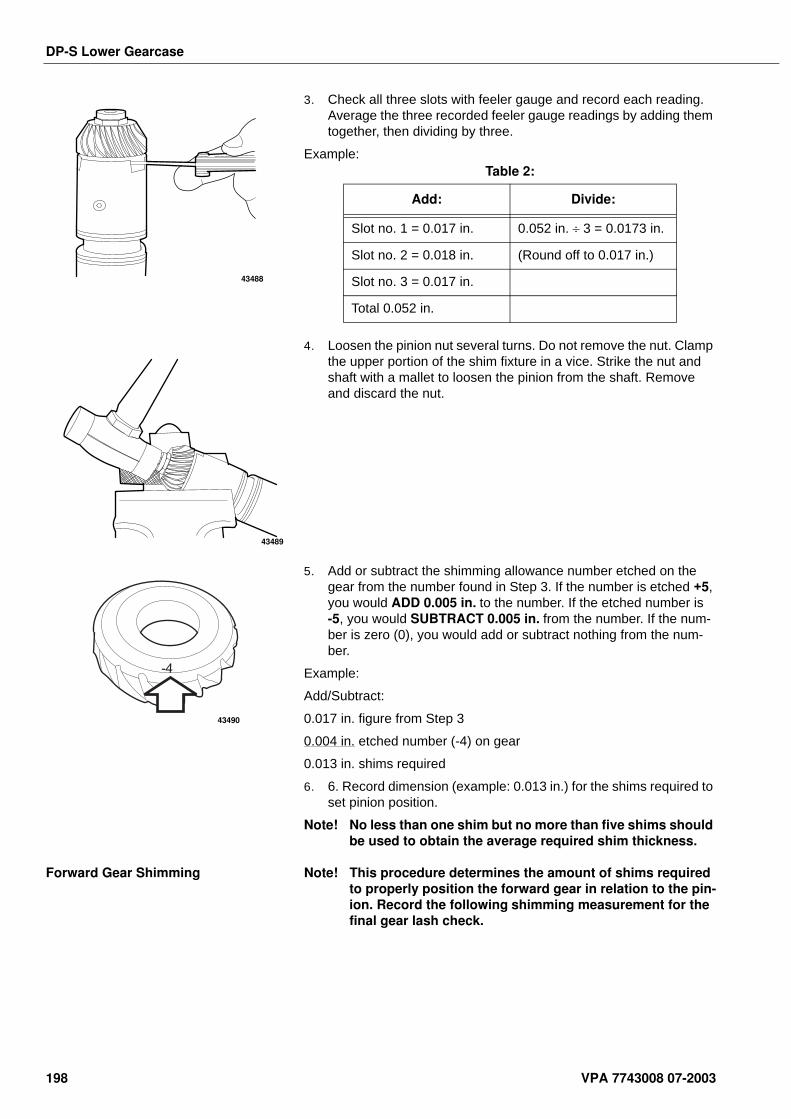
DP-S Lower Gearcase
3. Check all three slots with feeler gauge and record each reading. Average the three recorded feeler gauge readings by adding them together, then dividing by three.
Example:
4. Loosen the pinion nut several turns. Do not remove the nut. Clamp the upper portion of the shim fixture in a vice. Strike the nut and shaft with a mallet to loosen the pinion from the shaft. Remove and discard the nut.
5. Add or subtract the shimming allowance number etched on the gear from the number found in Step 3. If the number is etched +5, you would ADD 0.005 in. to the number. If the etched number is -5, you would SUBTRACT 0.005 in. from the number. If the num-ber is zero (0), you would add or subtract nothing from the num-ber.
Example:
Add/Subtract:
0.017 in. figure from Step 3
0.004 in. etched number (-4) on gear
0.013 in. shims required
6. 6. Record dimension (example: 0.013 in.) for the shims required to set pinion position.
Note! No less than one shim but no more than five shims should be used to obtain the average required shim thickness.
Forward Gear Shimming Note! This procedure determines the amount of shims required to properly position the forward gear in relation to the pin-ion. Record the following shimming measurement for the final gear lash check.
43488
Table 2:
Add: Divide:
Slot no. 1 = 0.017 in. 0.052 in. ÷ 3 = 0.0173 in.
Slot no. 2 = 0.018 in. (Round off to 0.017 in.)
Slot no. 3 = 0.017 in.
Total 0.052 in.
43489
-4
43490
198 VPA 7743008 07-2003
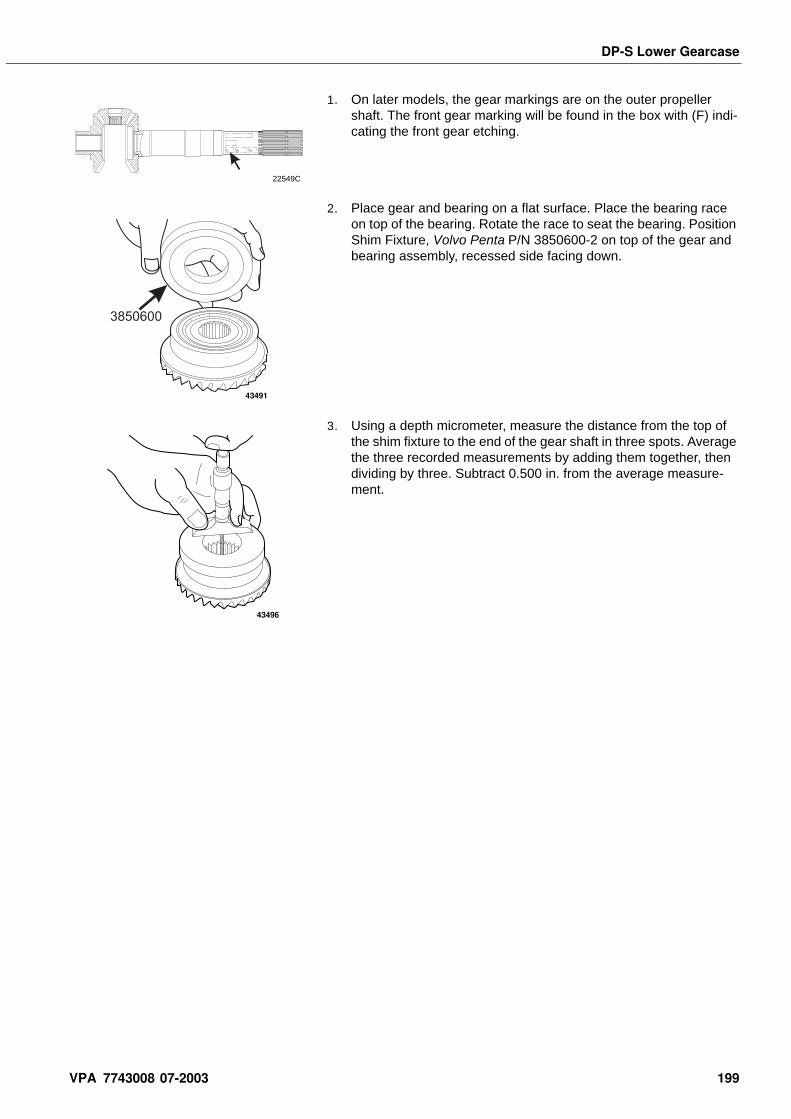
DP-S Lower Gearcase
1. On later models, the gear markings are on the outer propeller shaft. The front gear marking will be found in the box with (F) indi-cating the front gear etching.
2. Place gear and bearing on a flat surface. Place the bearing race on top of the bearing. Rotate the race to seat the bearing. Position Shim Fixture, Volvo Penta P/N 3850600-2 on top of the gear and bearing assembly, recessed side facing down.
3. Using a depth micrometer, measure the distance from the top of the shim fixture to the end of the gear shaft in three spots. Average the three recorded measurements by adding them together, then dividing by three. Subtract 0.500 in. from the average measure-ment.
22549C
(R) (P)(F)
3850600
43491
43496
VPA 7743008 07-2003 199
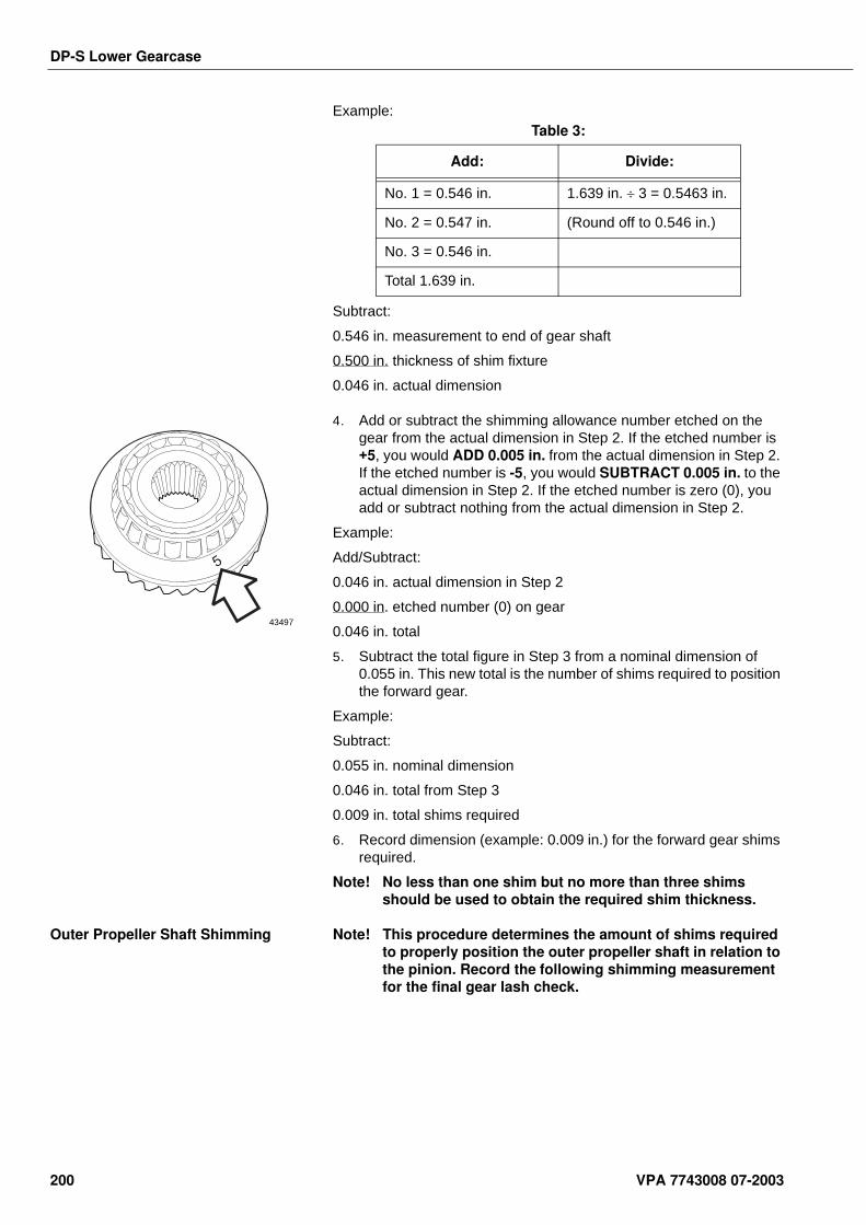
DP-S Lower Gearcase
Example:
Subtract:
0.546 in. measurement to end of gear shaft
0.500 in. thickness of shim fixture
0.046 in. actual dimension
4. Add or subtract the shimming allowance number etched on the gear from the actual dimension in Step 2. If the etched number is +5, you would ADD 0.005 in. from the actual dimension in Step 2. If the etched number is -5, you would SUBTRACT 0.005 in. to the actual dimension in Step 2. If the etched number is zero (0), you add or subtract nothing from the actual dimension in Step 2.
Example:
Add/Subtract:
0.046 in. actual dimension in Step 2
0.000 in. etched number (0) on gear
0.046 in. total
5. Subtract the total figure in Step 3 from a nominal dimension of 0.055 in. This new total is the number of shims required to position the forward gear.
Example:
Subtract:
0.055 in. nominal dimension
0.046 in. total from Step 3
0.009 in. total shims required
6. Record dimension (example: 0.009 in.) for the forward gear shims required.
Note! No less than one shim but no more than three shims should be used to obtain the required shim thickness.
Outer Propeller Shaft Shimming Note! This procedure determines the amount of shims required to properly position the outer propeller shaft in relation to the pinion. Record the following shimming measurement for the final gear lash check.
Table 3:
Add: Divide:
No. 1 = 0.546 in. 1.639 in. ÷ 3 = 0.5463 in.
No. 2 = 0.547 in. (Round off to 0.546 in.)
No. 3 = 0.546 in.
Total 1.639 in.
5
43497
200 VPA 7743008 07-2003
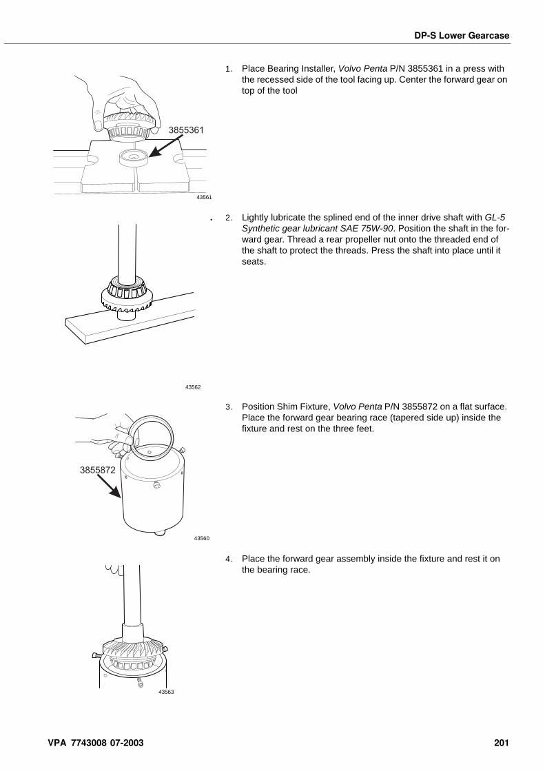
DP-S Lower Gearcase
1. Place Bearing Installer, Volvo Penta P/N 3855361 in a press with the recessed side of the tool facing up. Center the forward gear on top of the tool
. 2. Lightly lubricate the splined end of the inner drive shaft with GL-5 Synthetic gear lubricant SAE 75W-90. Position the shaft in the for-ward gear. Thread a rear propeller nut onto the threaded end of the shaft to protect the threads. Press the shaft into place until it seats.
3. Position Shim Fixture, Volvo Penta P/N 3855872 on a flat surface. Place the forward gear bearing race (tapered side up) inside the fixture and rest on the three feet.
4. Place the forward gear assembly inside the fixture and rest it on the bearing race.
3855361
43561
43562
3855872
43560
43563
VPA 7743008 07-2003 201
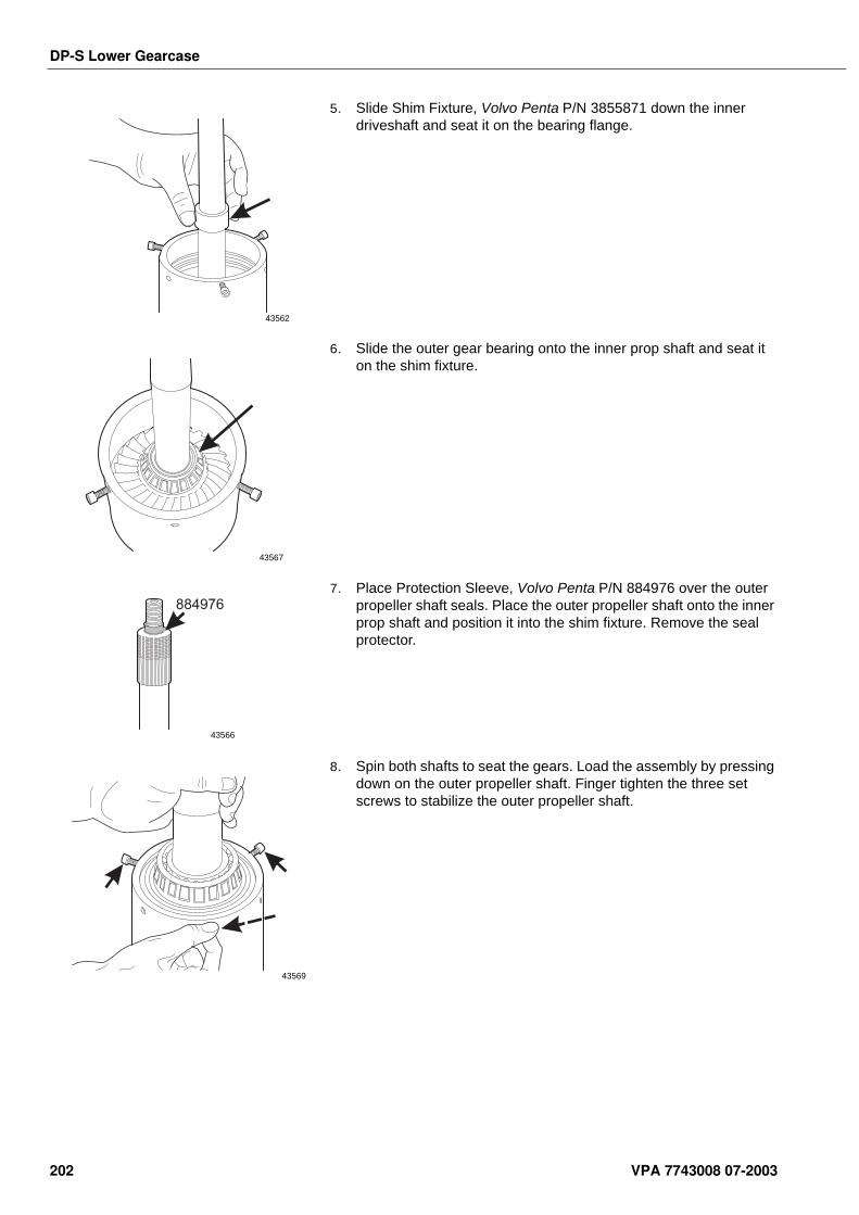
DP-S Lower Gearcase
5. Slide Shim Fixture, Volvo Penta P/N 3855871 down the inner driveshaft and seat it on the bearing flange.
6. Slide the outer gear bearing onto the inner prop shaft and seat it on the shim fixture.
7. Place Protection Sleeve, Volvo Penta P/N 884976 over the outer propeller shaft seals. Place the outer propeller shaft onto the inner prop shaft and position it into the shim fixture. Remove the seal protector.
8. Spin both shafts to seat the gears. Load the assembly by pressing down on the outer propeller shaft. Finger tighten the three set screws to stabilize the outer propeller shaft.
43562
43567
884976
43566
43569
202 VPA 7743008 07-2003
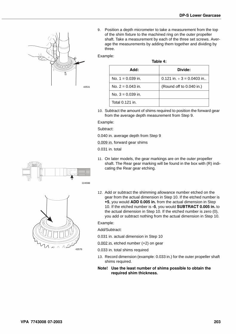
DP-S Lower Gearcase
9. Position a depth micrometer to take a measurement from the top of the shim fixture to the machined ring on the outer propeller shaft. Take a measurement by each of the three set screws. Aver-age the measurements by adding them together and dividing by three.
Example:
10. Subtract the amount of shims required to position the forward gear from the average depth measurement from Step 9.
Example:
Subtract:
0.040 in. average depth from Step 9
0.009 in. forward gear shims
0.031 in. total
11. On later models, the gear markings are on the outer propeller shaft. The Rear gear marking will be found in the box with (R) indi-cating the Rear gear etching.
12. Add or subtract the shimming allowance number etched on the gear from the actual dimension in Step 10. If the etched number is +5, you would ADD 0.005 in. from the actual dimension in Step 10. If the etched number is -5, you would SUBTRACT 0.005 in. to the actual dimension in Step 10. If the etched number is zero (0), you add or subtract nothing from the actual dimension in Step 10.
Example:
Add/Subtract:
0.031 in. actual dimension in Step 10
0.002 in. etched number (+2) on gear
0.033 in. total shims required
13. Record dimension (example: 0.033 in.) for the outer propeller shaft shims required.
Note! Use the least number of shims possible to obtain the required shim thickness.
43531
Table 4:
Add: Divide:
No. 1 = 0.039 in. 0.121 in. ÷ 3 = 0.0403 in..
No. 2 = 0.043 in. (Round off to 0.040 in.)
No. 3 = 0.039 in.
Total 0.121 in.
(R) (P)(F)
22459B
43578
VPA 7743008 07-2003 203

DP-S Lower Gearcase
Oil Screen Service - Upper Housing
Remove the oil screen from the upper gear housing. Clean and replace as necessary. Install the oil screen into the oil passage in the upper gear housing. Make sure the screen is secure.
Exhaust Cover Service
1. Remove two screws and remove exhaust cover. Remove and dis-card seal.
2. Apply Loctite Gasket Adhesive (yellow) to the exhaust cover groove and install a new seal.
3. Apply Loctite Primer to the two screws and let air dry. Apply Loctite 242 to the screw threads. Install the cover and secure with two screws. Tighten the screws to 14-17 ft. lb. (19,5-22,5 N•m).
43675
43626
43628
43626
204 VPA 7743008 07-2003
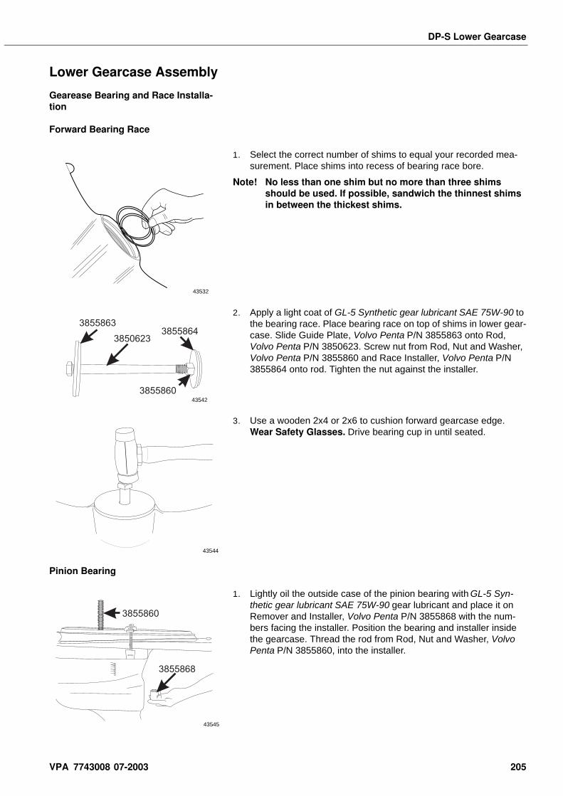
DP-S Lower Gearcase
Lower Gearcase Assembly
Gearease Bearing and Race Installa-tion
Forward Bearing Race
1. Select the correct number of shims to equal your recorded mea-surement. Place shims into recess of bearing race bore.
Note! No less than one shim but no more than three shims should be used. If possible, sandwich the thinnest shims in between the thickest shims.
2. Apply a light coat of GL-5 Synthetic gear lubricant SAE 75W-90 to the bearing race. Place bearing race on top of shims in lower gear-case. Slide Guide Plate, Volvo Penta P/N 3855863 onto Rod, Volvo Penta P/N 3850623. Screw nut from Rod, Nut and Washer, Volvo Penta P/N 3855860 and Race Installer, Volvo Penta P/N 3855864 onto rod. Tighten the nut against the installer.
3. Use a wooden 2x4 or 2x6 to cushion forward gearcase edge. Wear Safety Glasses. Drive bearing cup in until seated.
Pinion Bearing
1. Lightly oil the outside case of the pinion bearing with GL-5 Syn-thetic gear lubricant SAE 75W-90 gear lubricant and place it on Remover and Installer, Volvo Penta P/N 3855868 with the num-bers facing the installer. Position the bearing and installer inside the gearcase. Thread the rod from Rod, Nut and Washer, Volvo Penta P/N 3855860, into the installer.
43532
3855863
3850623
3855860
3855864
43542
43544
3855868
3855860
43545
VPA 7743008 07-2003 205
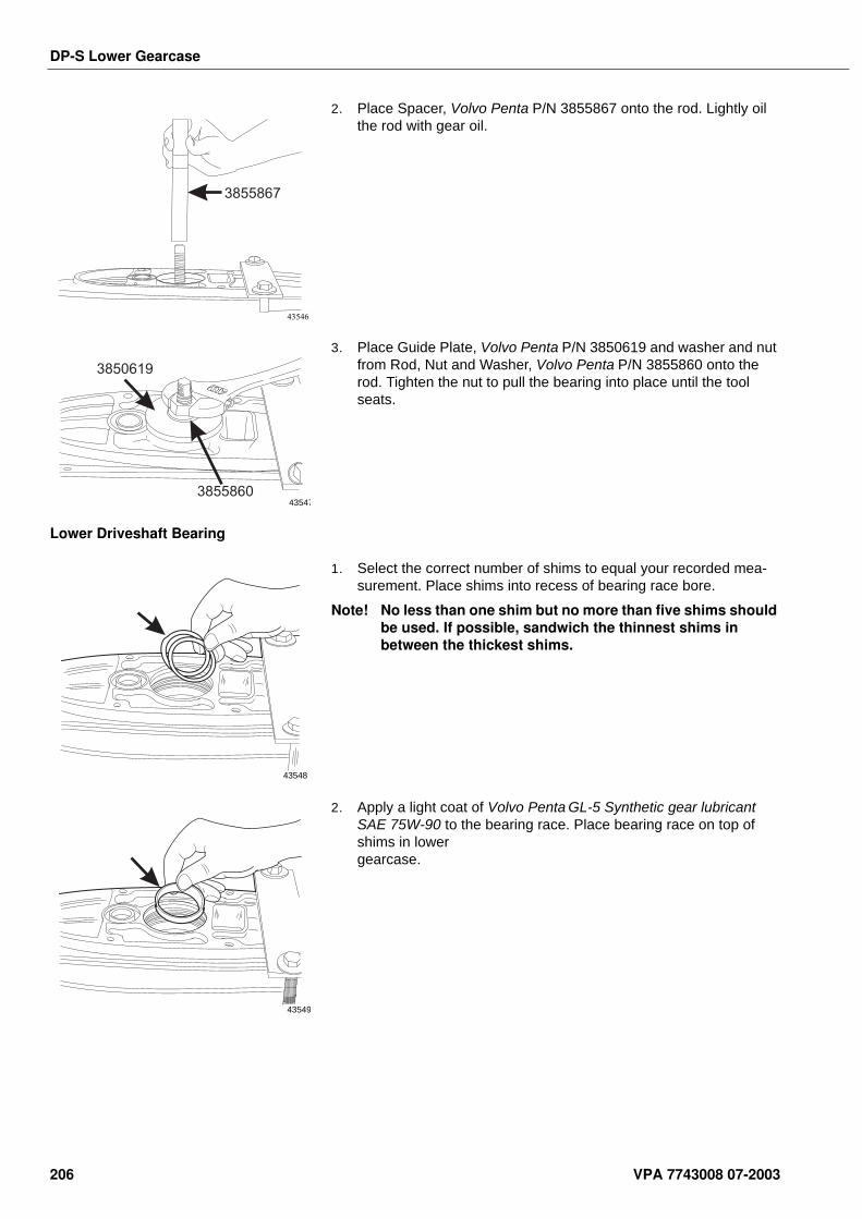
DP-S Lower Gearcase
2. Place Spacer, Volvo Penta P/N 3855867 onto the rod. Lightly oil the rod with gear oil.
3. Place Guide Plate, Volvo Penta P/N 3850619 and washer and nut from Rod, Nut and Washer, Volvo Penta P/N 3855860 onto the rod. Tighten the nut to pull the bearing into place until the tool seats.
Lower Driveshaft Bearing
1. Select the correct number of shims to equal your recorded mea-surement. Place shims into recess of bearing race bore.
Note! No less than one shim but no more than five shims should be used. If possible, sandwich the thinnest shims in between the thickest shims.
2. Apply a light coat of Volvo Penta GL-5 Synthetic gear lubricant SAE 75W-90 to the bearing race. Place bearing race on top of shims in lower gearcase.
3855867
43546
3850619
385586043547
43548
43549
206 VPA 7743008 07-2003
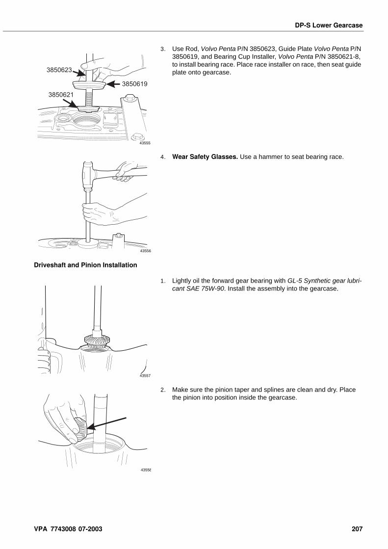
DP-S Lower Gearcase
3. Use Rod, Volvo Penta P/N 3850623, Guide Plate Volvo Penta P/N 3850619, and Bearing Cup Installer, Volvo Penta P/N 3850621-8, to install bearing race. Place race installer on race, then seat guide plate onto gearcase.
4. Wear Safety Glasses. Use a hammer to seat bearing race.
Driveshaft and Pinion Installation
1. Lightly oil the forward gear bearing with GL-5 Synthetic gear lubri-cant SAE 75W-90. Install the assembly into the gearcase.
2. Make sure the pinion taper and splines are clean and dry. Place the pinion into position inside the gearcase.
3850623
3850619
3850621
43555
43556
43557
43558
VPA 7743008 07-2003 207
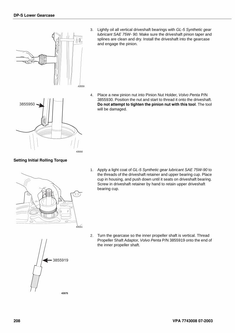
DP-S Lower Gearcase
3. Lightly oil all vertical driveshaft bearings with GL-5 Synthetic gear lubricant SAE 75W- 90. Make sure the driveshaft pinion taper and splines are clean and dry. Install the driveshaft into the gearcase and engage the pinion.
4. Place a new pinion nut into Pinion Nut Holder, Volvo Penta P/N 3855930. Position the nut and start to thread it onto the driveshaft. Do not attempt to tighten the pinion nut with this tool. The tool will be damaged.
Setting Initial Rolling Torque
1. Apply a light coat of GL-5 Synthetic gear lubricant SAE 75W-90 to the threads of the driveshaft retainer and upper bearing cup. Place cup in housing, and push down until it seats on driveshaft bearing. Screw in driveshaft retainer by hand to retain upper driveshaft bearing cup.
2. Turn the gearcase so the inner propeller shaft is vertical. Thread Propeller Shaft Adaptor, Volvo Penta P/N 3855919 onto the end of the inner propeller shaft.
43559
3855950
43550
43551
3855919
43575
208 VPA 7743008 07-2003
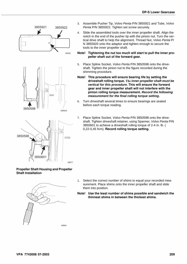
DP-S Lower Gearcase
3. Assemble Pusher Tip, Volvo Penta P/N 3855921 and Tube, Volvo Penta P/N 3855922. Tighten set screw securely.
4. Slide the assembled tools over the inner propeller shaft. Align the notch in the end of the pusher tip with the pinion nut. Turn the ver-tical drive shaft to help the alignment. Thread Nut, Volvo Penta P/N 3855920 onto the adaptor and tighten enough to secure the tools to the inner propeller shaft.
Note! Tightening the nut too much will start to pull the inner pro-peller shaft out of the forward gear.
5. Place Spline Socket, Volvo Penta P/N 3850598 onto the drive-shaft. Tighten the pinion nut to the figure recorded during the shimming procedure.
Note! This procedure will ensure bearing life by setting the driveshaft rolling torque. The inner propeller shaft must be vertical for this procedure. This will ensure the forward gear and inner propeller shaft will not interfere with the pinion rolling torque measurement. Record the following measurement for the final rolling torque setting.
6. Turn driveshaft several times to ensure bearings are seated before each torque reading.
7. Place Spline Socket, Volvo Penta P/N 3850598 onto the drive-shaft. Tighten driveshaft retainer, using Spanner, Volvo Penta P/N 3850601 to achieve a driveshaft rolling torque of 2-4 in. lb. (0,22-0,45 N•m). Record rolling torque setting.
Propeller Shaft Housing and Propeller Shaft Installation
1. Select the correct number of shims to equal your recorded mea-surement. Place shims onto the inner propeller shaft and slide them into position.
Note! Use the least number of shims possible and sandwich the thinnest shims in between the thickest shims.
3855921 3855922
43432
385059843552A
3850598
3850601
43577
43554
VPA 7743008 07-2003 209
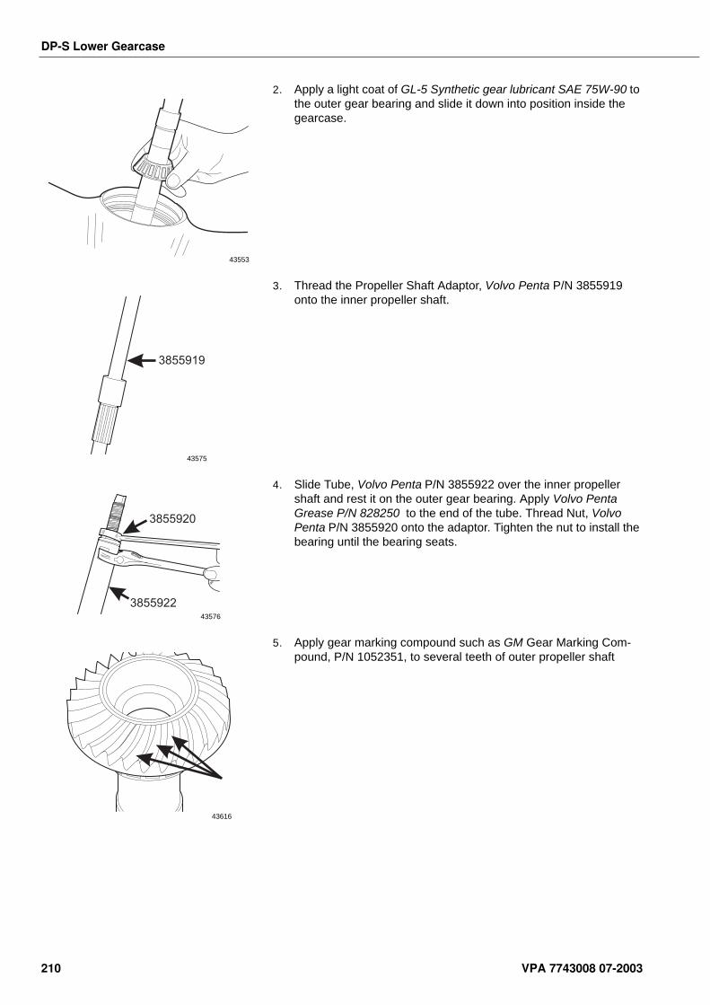
DP-S Lower Gearcase
2. Apply a light coat of GL-5 Synthetic gear lubricant SAE 75W-90 to the outer gear bearing and slide it down into position inside the gearcase.
3. Thread the Propeller Shaft Adaptor, Volvo Penta P/N 3855919 onto the inner propeller shaft.
4. Slide Tube, Volvo Penta P/N 3855922 over the inner propeller shaft and rest it on the outer gear bearing. Apply Volvo Penta Grease P/N 828250 to the end of the tube. Thread Nut, Volvo Penta P/N 3855920 onto the adaptor. Tighten the nut to install the bearing until the bearing seats.
5. Apply gear marking compound such as GM Gear Marking Com-pound, P/N 1052351, to several teeth of outer propeller shaft
43553
3855919
43575
3855922
3855920
43576
43616
210 VPA 7743008 07-2003
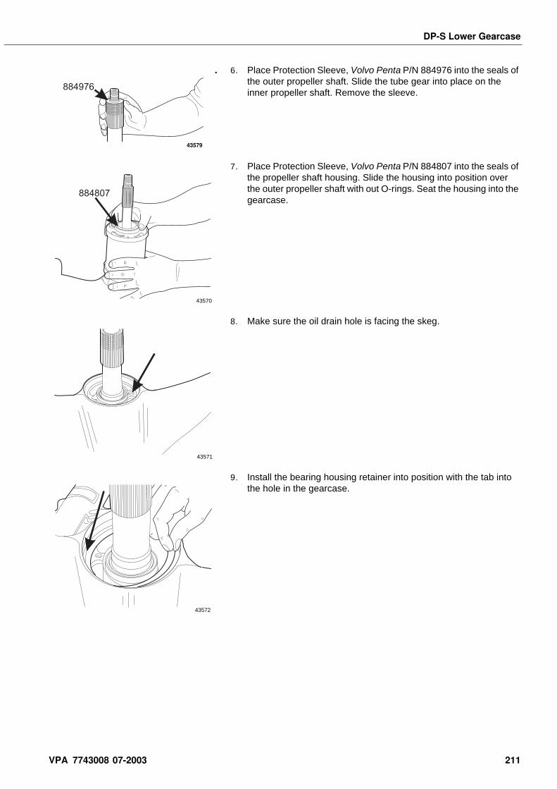
DP-S Lower Gearcase
. 6. Place Protection Sleeve, Volvo Penta P/N 884976 into the seals of the outer propeller shaft. Slide the tube gear into place on the inner propeller shaft. Remove the sleeve.
7. Place Protection Sleeve, Volvo Penta P/N 884807 into the seals of the propeller shaft housing. Slide the housing into position over the outer propeller shaft with out O-rings. Seat the housing into the gearcase.
8. Make sure the oil drain hole is facing the skeg.
9. Install the bearing housing retainer into position with the tab into the hole in the gearcase.
884976
43579
884807
43570
43571
43572
VPA 7743008 07-2003 211
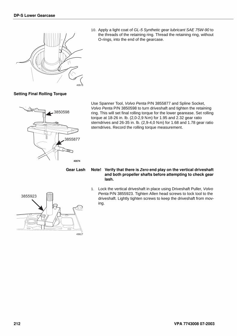
DP-S Lower Gearcase
10. Apply a light coat of GL-5 Synthetic gear lubricant SAE 75W-90 to the threads of the retaining ring. Thread the retaining ring, without O-rings, into the end of the gearcase.
Setting Final Rolling Torque
Use Spanner Tool, Volvo Penta P/N 3855877 and Spline Socket, Volvo Penta P/N 3850598 to turn driveshaft and tighten the retaining ring. This will set final rolling torque for the lower gearease. Set rolling torque at 18-26 in. lb. (2,0-2,9 N•m) for 1.95 and 2.32 gear ratio sterndrives and 26-35 in. lb. (2,9-4,0 N•m) for 1.68 and 1.78 gear ratio sterndrives. Record the rolling torque measurement.
Gear Lash Note! Verify that there is Zero end play on the vertical driveshaft and both propeller shafts before attempting to check gear lash.
1. Lock the vertical driveshaft in place using Driveshaft Puller, Volvo Penta P/N 3855923. Tighten Allen head screws to lock tool to the driveshaft. Lightly tighten screws to keep the driveshaft from mov-ing.
43573
3855877
3850598
43574
3855923
43617
212 VPA 7743008 07-2003
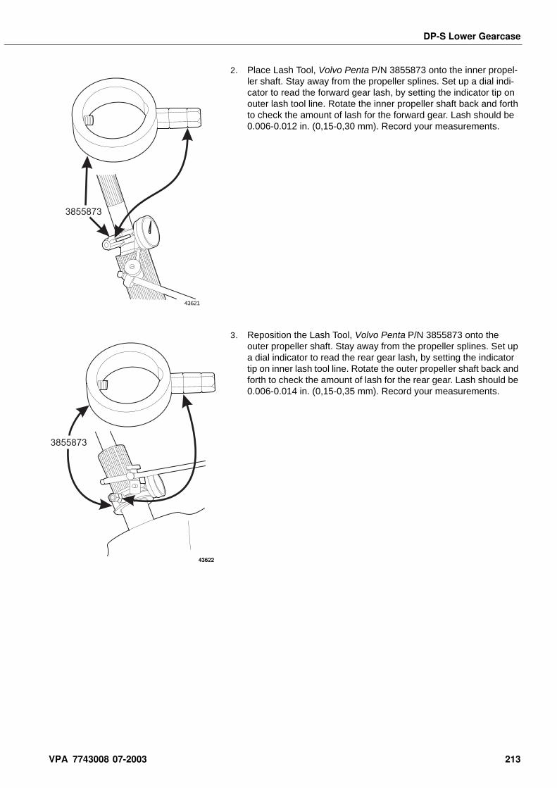
DP-S Lower Gearcase
2. Place Lash Tool, Volvo Penta P/N 3855873 onto the inner propel-ler shaft. Stay away from the propeller splines. Set up a dial indi-cator to read the forward gear lash, by setting the indicator tip on outer lash tool line. Rotate the inner propeller shaft back and forth to check the amount of lash for the forward gear. Lash should be 0.006-0.012 in. (0,15-0,30 mm). Record your measurements.
3. Reposition the Lash Tool, Volvo Penta P/N 3855873 onto the outer propeller shaft. Stay away from the propeller splines. Set up a dial indicator to read the rear gear lash, by setting the indicator tip on inner lash tool line. Rotate the outer propeller shaft back and forth to check the amount of lash for the rear gear. Lash should be 0.006-0.014 in. (0,15-0,35 mm). Record your measurements.
3855873
43621
3855873
43622
VPA 7743008 07-2003 213
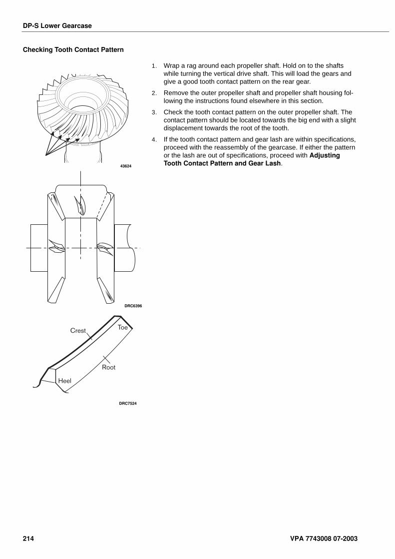
DP-S Lower Gearcase
Checking Tooth Contact Pattern
1. Wrap a rag around each propeller shaft. Hold on to the shafts while turning the vertical drive shaft. This will load the gears and give a good tooth contact pattern on the rear gear.
2. Remove the outer propeller shaft and propeller shaft housing fol-lowing the instructions found elsewhere in this section.
3. Check the tooth contact pattern on the outer propeller shaft. The contact pattern should be located towards the big end with a slight displacement towards the root of the tooth.
4. If the tooth contact pattern and gear lash are within specifications, proceed with the reassembly of the gearcase. If either the pattern or the lash are out of specifications, proceed with Adjusting Tooth Contact Pattern and Gear Lash.43624
DRC6396
DRC7524
214 VPA 7743008 07-2003
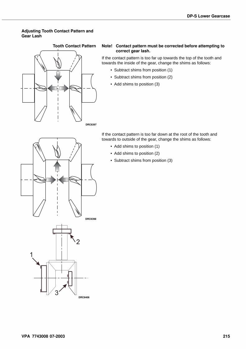
DP-S Lower Gearcase
Adjusting Tooth Contact Pattern and Gear Lash
Tooth Contact Pattern Note! Contact pattern must be corrected before attempting to correct gear lash.
If the contact pattern is too far up towards the top of the tooth and towards the inside of the gear, change the shims as follows:
• Subtract shims from position (1)
• Subtract shims from position (2)
• Add shims to position (3)
If the contact pattern is too far down at the root of the tooth and towards to outside of the gear, change the shims as follows:
• Add shims to position (1)
• Add shims to position (2)
• Subtract shims from position (3)
DRC6397
DRC6398
1
3
2
DRC6406
VPA 7743008 07-2003 215
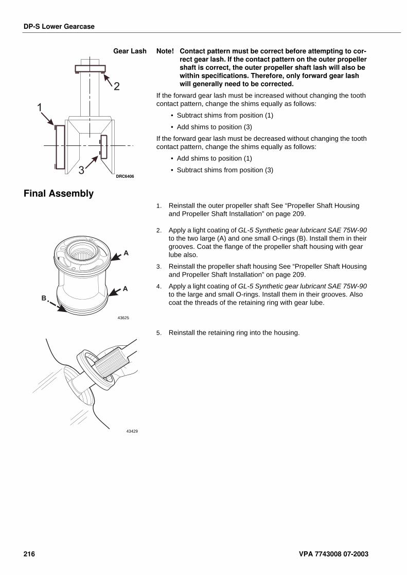
DP-S Lower Gearcase
Gear Lash Note! Contact pattern must be correct before attempting to cor-rect gear lash. If the contact pattern on the outer propeller shaft is correct, the outer propeller shaft lash will also be within specifications. Therefore, only forward gear lash will generally need to be corrected.
If the forward gear lash must be increased without changing the tooth contact pattern, change the shims equally as follows:
• Subtract shims from position (1)
• Add shims to position (3)
If the forward gear lash must be decreased without changing the tooth contact pattern, change the shims equally as follows:
• Add shims to position (1)
• Subtract shims from position (3)
Final Assembly1. Reinstall the outer propeller shaft See “Propeller Shaft Housing
and Propeller Shaft Installation” on page 209.
2. Apply a light coating of GL-5 Synthetic gear lubricant SAE 75W-90 to the two large (A) and one small O-rings (B). Install them in their grooves. Coat the flange of the propeller shaft housing with gear lube also.
3. Reinstall the propeller shaft housing See “Propeller Shaft Housing and Propeller Shaft Installation” on page 209.
4. Apply a light coating of GL-5 Synthetic gear lubricant SAE 75W-90 to the large and small O-rings. Install them in their grooves. Also coat the threads of the retaining ring with gear lube.
5. Reinstall the retaining ring into the housing.
1
3
2
DRC6406
A
A
B
43625
43429
216 VPA 7743008 07-2003
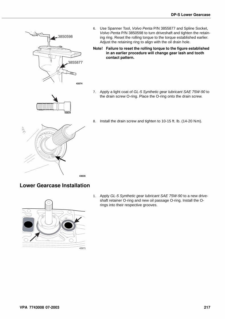
DP-S Lower Gearcase
6. Use Spanner Tool, Volvo Penta P/N 3855877 and Spline Socket, Volvo Penta P/N 3850598 to turn driveshaft and tighten the retain-ing ring. Reset the rolling torque to the torque established earlier. Adjust the retaining ring to align with the oil drain hole.
Note! Failure to reset the rolling torque to the figure established in an earlier procedure will change gear lash and tooth contact pattern.
7. Apply a light coat of GL-5 Synthetic gear lubricant SAE 75W-90 to the drain screw O-ring. Place the O-ring onto the drain screw.
8. Install the drain screw and tighten to 10-15 ft. lb. (14-20 N•m).
Lower Gearcase Installation
1. Apply GL-5 Synthetic gear lubricant SAE 75W-90 to a new drive-shaft retainer O-ring and new oil passage O-ring. Install the O-rings into their respective grooves.
3855877
3850598
43574
43634
43635
42671
VPA 7743008 07-2003 217
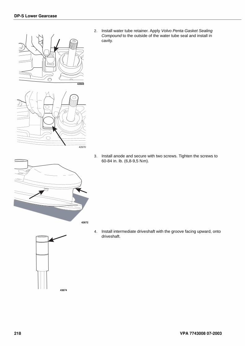
DP-S Lower Gearcase
2. Install water tube retainer. Apply Volvo Penta Gasket Sealing Compound to the outside of the water tube seal and install in cavity.
3. Install anode and secure with two screws. Tighten the screws to 60-84 in. lb. (6,8-9,5 N•m).
4. Install intermediate driveshaft with the groove facing upward, onto driveshaft.
42669
42670
42672
43674
218 VPA 7743008 07-2003
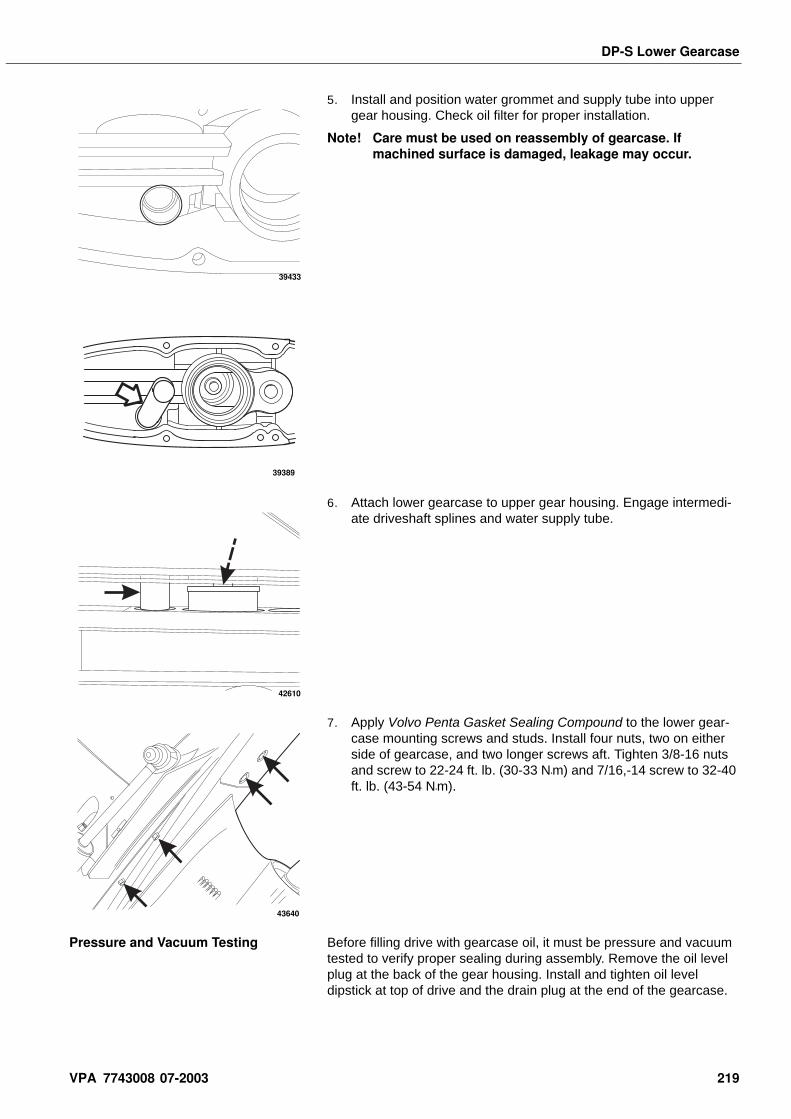
DP-S Lower Gearcase
5. Install and position water grommet and supply tube into upper gear housing. Check oil filter for proper installation.
Note! Care must be used on reassembly of gearcase. If machined surface is damaged, leakage may occur.
6. Attach lower gearcase to upper gear housing. Engage intermedi-ate driveshaft splines and water supply tube.
7. Apply Volvo Penta Gasket Sealing Compound to the lower gear-case mounting screws and studs. Install four nuts, two on either side of gearcase, and two longer screws aft. Tighten 3/8-16 nuts and screw to 22-24 ft. lb. (30-33 N•m) and 7/16,-14 screw to 32-40 ft. lb. (43-54 N•m).
Pressure and Vacuum Testing Before filling drive with gearcase oil, it must be pressure and vacuum tested to verify proper sealing during assembly. Remove the oil level plug at the back of the gear housing. Install and tighten oil level dipstick at top of drive and the drain plug at the end of the gearcase.
39433
39389
42610
43640
VPA 7743008 07-2003 219
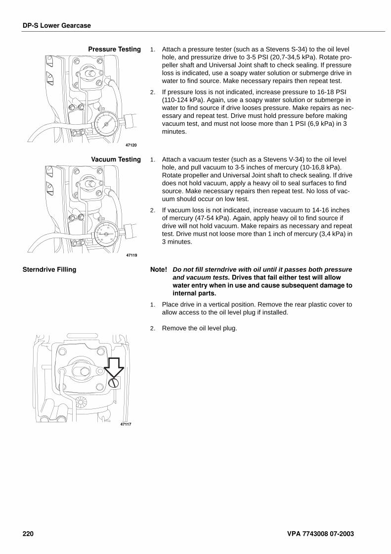
DP-S Lower Gearcase
Pressure Testing 1. Attach a pressure tester (such as a Stevens S-34) to the oil level hole, and pressurize drive to 3-5 PSI (20,7-34,5 kPa). Rotate pro-peller shaft and Universal Joint shaft to check sealing. If pressure loss is indicated, use a soapy water solution or submerge drive in water to find source. Make necessary repairs then repeat test.
2. If pressure loss is not indicated, increase pressure to 16-18 PSI (110-124 kPa). Again, use a soapy water solution or submerge in water to find source if drive looses pressure. Make repairs as nec-essary and repeat test. Drive must hold pressure before making vacuum test, and must not loose more than 1 PSI (6,9 kPa) in 3 minutes.
Vacuum Testing 1. Attach a vacuum tester (such as a Stevens V-34) to the oil level hole, and pull vacuum to 3-5 inches of mercury (10-16,8 kPa). Rotate propeller and Universal Joint shaft to check sealing. If drive does not hold vacuum, apply a heavy oil to seal surfaces to find source. Make necessary repairs then repeat test. No loss of vac-uum should occur on low test.
2. If vacuum loss is not indicated, increase vacuum to 14-16 inches of mercury (47-54 kPa). Again, apply heavy oil to find source if drive will not hold vacuum. Make repairs as necessary and repeat test. Drive must not loose more than 1 inch of mercury (3,4 kPa) in 3 minutes.
Sterndrive Filling Note! Do not fill sterndrive with oil until it passes both pressure and vacuum tests. Drives that fail either test will allow water entry when in use and cause subsequent damage to internal parts.
1. Place drive in a vertical position. Remove the rear plastic cover to allow access to the oil level plug if installed.
2. Remove the oil level plug.
47120
15
15
30 30
0
47119
47117
220 VPA 7743008 07-2003
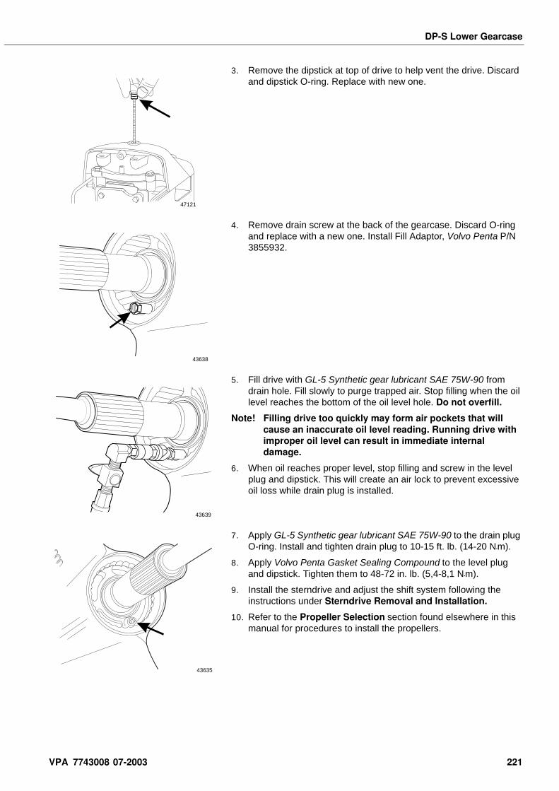
DP-S Lower Gearcase
3. Remove the dipstick at top of drive to help vent the drive. Discard and dipstick O-ring. Replace with new one.
4. Remove drain screw at the back of the gearcase. Discard O-ring and replace with a new one. Install Fill Adaptor, Volvo Penta P/N 3855932.
5. Fill drive with GL-5 Synthetic gear lubricant SAE 75W-90 from drain hole. Fill slowly to purge trapped air. Stop filling when the oil level reaches the bottom of the oil level hole. Do not overfill.
Note! Filling drive too quickly may form air pockets that will cause an inaccurate oil level reading. Running drive with improper oil level can result in immediate internal damage.
6. When oil reaches proper level, stop filling and screw in the level plug and dipstick. This will create an air lock to prevent excessive oil loss while drain plug is installed.
7. Apply GL-5 Synthetic gear lubricant SAE 75W-90 to the drain plug O-ring. Install and tighten drain plug to 10-15 ft. lb. (14-20 N•m).
8. Apply Volvo Penta Gasket Sealing Compound to the level plug and dipstick. Tighten them to 48-72 in. lb. (5,4-8,1 N•m).
9. Install the sterndrive and adjust the shift system following the instructions under Sterndrive Removal and Installation.
10. Refer to the Propeller Selection section found elsewhere in this manual for procedures to install the propellers.
47121
43638
43639
43635
VPA 7743008 07-2003 221
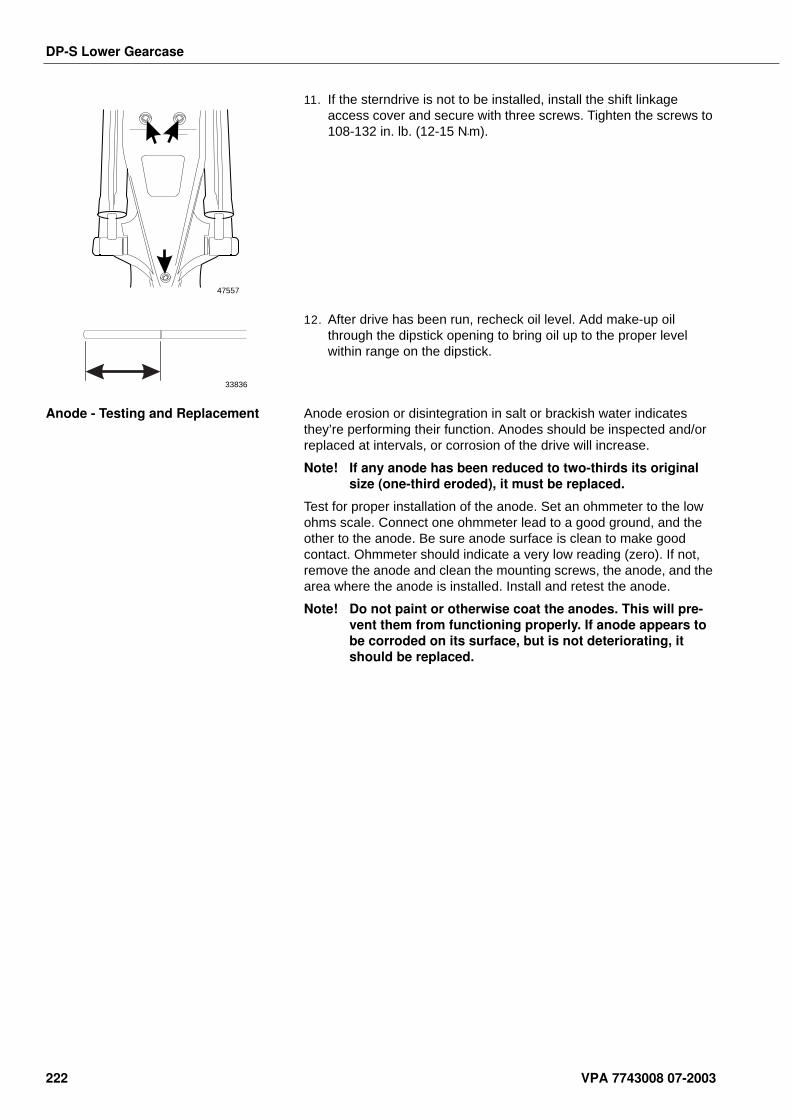
DP-S Lower Gearcase
11. If the sterndrive is not to be installed, install the shift linkage access cover and secure with three screws. Tighten the screws to 108-132 in. lb. (12-15 N•m).
12. After drive has been run, recheck oil level. Add make-up oil through the dipstick opening to bring oil up to the proper level within range on the dipstick.
Anode - Testing and Replacement Anode erosion or disintegration in salt or brackish water indicates they’re performing their function. Anodes should be inspected and/or replaced at intervals, or corrosion of the drive will increase.
Note! If any anode has been reduced to two-thirds its original size (one-third eroded), it must be replaced.
Test for proper installation of the anode. Set an ohmmeter to the low ohms scale. Connect one ohmmeter lead to a good ground, and the other to the anode. Be sure anode surface is clean to make good contact. Ohmmeter should indicate a very low reading (zero). If not, remove the anode and clean the mounting screws, the anode, and the area where the anode is installed. Install and retest the anode.
Note! Do not paint or otherwise coat the anodes. This will pre-vent them from functioning properly. If anode appears to be corroded on its surface, but is not deteriorating, it should be replaced.
47557
33836
222 VPA 7743008 07-2003
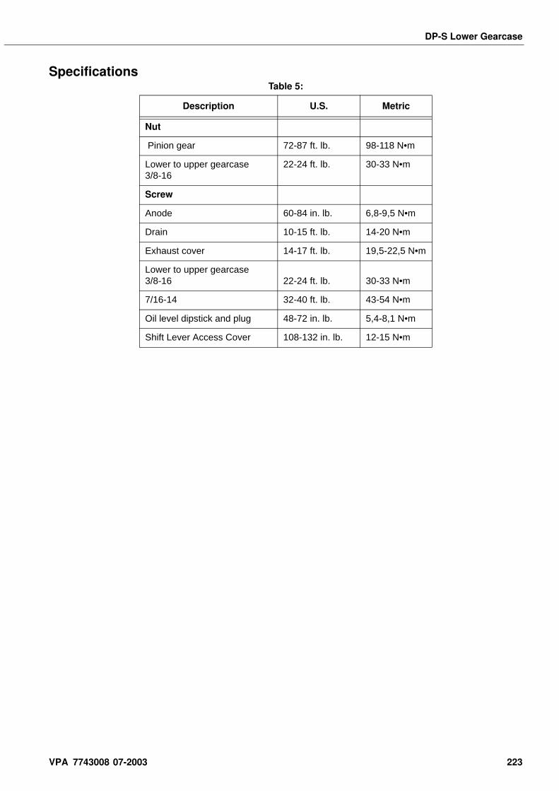
DP-S Lower Gearcase
SpecificationsTable 5:
Description U.S. Metric
Nut
Pinion gear 72-87 ft. lb. 98-118 N•m
Lower to upper gearcase 3/8-16
22-24 ft. lb. 30-33 N•m
Screw
Anode 60-84 in. lb. 6,8-9,5 N•m
Drain 10-15 ft. lb. 14-20 N•m
Exhaust cover 14-17 ft. lb. 19,5-22,5 N•m
Lower to upper gearcase 3/8-16 22-24 ft. lb. 30-33 N•m
7/16-14 32-40 ft. lb. 43-54 N•m
Oil level dipstick and plug 48-72 in. lb. 5,4-8,1 N•m
Shift Lever Access Cover 108-132 in. lb. 12-15 N•m
VPA 7743008 07-2003 223
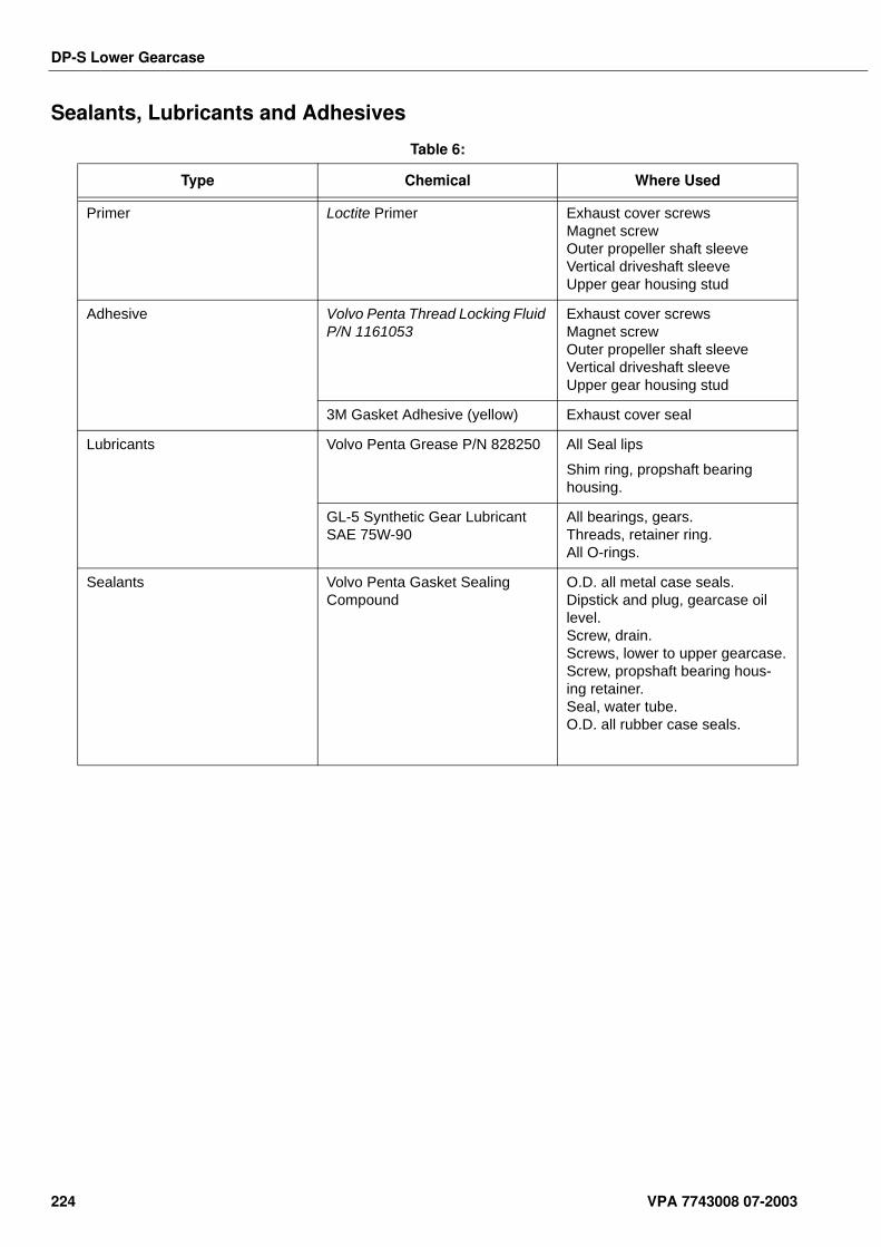
DP-S Lower Gearcase
Sealants, Lubricants and Adhesives
Table 6:
Type Chemical Where Used
Primer Loctite Primer Exhaust cover screwsMagnet screwOuter propeller shaft sleeveVertical driveshaft sleeveUpper gear housing stud
Adhesive Volvo Penta Thread Locking Fluid P/N 1161053
Exhaust cover screwsMagnet screwOuter propeller shaft sleeveVertical driveshaft sleeveUpper gear housing stud
3M Gasket Adhesive (yellow) Exhaust cover seal
Lubricants Volvo Penta Grease P/N 828250 All Seal lips
Shim ring, propshaft bearing housing.
GL-5 Synthetic Gear Lubricant SAE 75W-90
All bearings, gears.Threads, retainer ring.All O-rings.
Sealants Volvo Penta Gasket Sealing Compound
O.D. all metal case seals.Dipstick and plug, gearcase oil level.Screw, drain.Screws, lower to upper gearcase.Screw, propshaft bearing hous-ing retainer.Seal, water tube.O.D. all rubber case seals.
224 VPA 7743008 07-2003
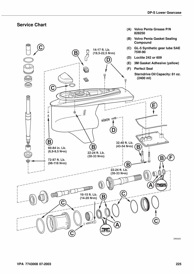
DP-S Lower Gearcase
Service Chart
CB
C
D
E
D
B
B
CB
C
C
C
B
BB
A
A
F72-87 ft. Lb.(98-118 N•m)
60-84 in. Lb.(6,9-9,5 N•m) 22-24 ft. Lb.
(30-33 N•m)
32-40 ft. Lb.(43-54 N•m)
22-24 ft. Lb.(30-33 N•m)
10-15 ft. Lb.(14-20 N•m)
14-17 ft. Lb.(19,5-22,5 N•m)
(A) Volvo Penta Grease P/N 828250
(B) Volvo Penta Gasket Sealing Compound
(C) GL-5 Synthetic gear lube SAE 75W-90
(D) Loctite 242 or 609
(E) 3M Gasket Adhesive (yellow)
(F) Perfect Seal
Sterndrive Oil Capacity: 81 oz. (2400 ml)
DR6400
VPA 7743008 07-2003 225

Notes . . . . . . . . . . . . . . . . . . . . . . . . . . . . . . . . . . . . . . . . . . . . . . . . . . . . . . . . . . . . . . . . . . . . . . . . . . .
. . . . . . . . . . . . . . . . . . . . . . . . . . . . . . . . . . . . . . . . . . . . . . . . . . . . . . . . . . . . . . . . . . . . . . . . . . .
. . . . . . . . . . . . . . . . . . . . . . . . . . . . . . . . . . . . . . . . . . . . . . . . . . . . . . . . . . . . . . . . . . . . . . . . . . .
. . . . . . . . . . . . . . . . . . . . . . . . . . . . . . . . . . . . . . . . . . . . . . . . . . . . . . . . . . . . . . . . . . . . . . . . . . .
. . . . . . . . . . . . . . . . . . . . . . . . . . . . . . . . . . . . . . . . . . . . . . . . . . . . . . . . . . . . . . . . . . . . . . . . . . .
. . . . . . . . . . . . . . . . . . . . . . . . . . . . . . . . . . . . . . . . . . . . . . . . . . . . . . . . . . . . . . . . . . . . . . . . . . .
. . . . . . . . . . . . . . . . . . . . . . . . . . . . . . . . . . . . . . . . . . . . . . . . . . . . . . . . . . . . . . . . . . . . . . . . . . .
. . . . . . . . . . . . . . . . . . . . . . . . . . . . . . . . . . . . . . . . . . . . . . . . . . . . . . . . . . . . . . . . . . . . . . . . . . .
. . . . . . . . . . . . . . . . . . . . . . . . . . . . . . . . . . . . . . . . . . . . . . . . . . . . . . . . . . . . . . . . . . . . . . . . . . .
. . . . . . . . . . . . . . . . . . . . . . . . . . . . . . . . . . . . . . . . . . . . . . . . . . . . . . . . . . . . . . . . . . . . . . . . . . .
. . . . . . . . . . . . . . . . . . . . . . . . . . . . . . . . . . . . . . . . . . . . . . . . . . . . . . . . . . . . . . . . . . . . . . . . . . .
. . . . . . . . . . . . . . . . . . . . . . . . . . . . . . . . . . . . . . . . . . . . . . . . . . . . . . . . . . . . . . . . . . . . . . . . . . .
. . . . . . . . . . . . . . . . . . . . . . . . . . . . . . . . . . . . . . . . . . . . . . . . . . . . . . . . . . . . . . . . . . . . . . . . . . .
. . . . . . . . . . . . . . . . . . . . . . . . . . . . . . . . . . . . . . . . . . . . . . . . . . . . . . . . . . . . . . . . . . . . . . . . . . .
. . . . . . . . . . . . . . . . . . . . . . . . . . . . . . . . . . . . . . . . . . . . . . . . . . . . . . . . . . . . . . . . . . . . . . . . . . .
. . . . . . . . . . . . . . . . . . . . . . . . . . . . . . . . . . . . . . . . . . . . . . . . . . . . . . . . . . . . . . . . . . . . . . . . . . .
. . . . . . . . . . . . . . . . . . . . . . . . . . . . . . . . . . . . . . . . . . . . . . . . . . . . . . . . . . . . . . . . . . . . . . . . . . .
. . . . . . . . . . . . . . . . . . . . . . . . . . . . . . . . . . . . . . . . . . . . . . . . . . . . . . . . . . . . . . . . . . . . . . . . . . .
. . . . . . . . . . . . . . . . . . . . . . . . . . . . . . . . . . . . . . . . . . . . . . . . . . . . . . . . . . . . . . . . . . . . . . . . . . .
. . . . . . . . . . . . . . . . . . . . . . . . . . . . . . . . . . . . . . . . . . . . . . . . . . . . . . . . . . . . . . . . . . . . . . . . . . .
. . . . . . . . . . . . . . . . . . . . . . . . . . . . . . . . . . . . . . . . . . . . . . . . . . . . . . . . . . . . . . . . . . . . . . . . . . .
. . . . . . . . . . . . . . . . . . . . . . . . . . . . . . . . . . . . . . . . . . . . . . . . . . . . . . . . . . . . . . . . . . . . . . . . . . .
. . . . . . . . . . . . . . . . . . . . . . . . . . . . . . . . . . . . . . . . . . . . . . . . . . . . . . . . . . . . . . . . . . . . . . . . . . .
. . . . . . . . . . . . . . . . . . . . . . . . . . . . . . . . . . . . . . . . . . . . . . . . . . . . . . . . . . . . . . . . . . . . . . . . . . .
. . . . . . . . . . . . . . . . . . . . . . . . . . . . . . . . . . . . . . . . . . . . . . . . . . . . . . . . . . . . . . . . . . . . . . . . . . .
. . . . . . . . . . . . . . . . . . . . . . . . . . . . . . . . . . . . . . . . . . . . . . . . . . . . . . . . . . . . . . . . . . . . . . . . . . .
. . . . . . . . . . . . . . . . . . . . . . . . . . . . . . . . . . . . . . . . . . . . . . . . . . . . . . . . . . . . . . . . . . . . . . . . . . .
. . . . . . . . . . . . . . . . . . . . . . . . . . . . . . . . . . . . . . . . . . . . . . . . . . . . . . . . . . . . . . . . . . . . . . . . . . .
. . . . . . . . . . . . . . . . . . . . . . . . . . . . . . . . . . . . . . . . . . . . . . . . . . . . . . . . . . . . . . . . . . . . . . . . . . .
. . . . . . . . . . . . . . . . . . . . . . . . . . . . . . . . . . . . . . . . . . . . . . . . . . . . . . . . . . . . . . . . . . . . . . . . . . .
. . . . . . . . . . . . . . . . . . . . . . . . . . . . . . . . . . . . . . . . . . . . . . . . . . . . . . . . . . . . . . . . . . . . . . . . . . .
. . . . . . . . . . . . . . . . . . . . . . . . . . . . . . . . . . . . . . . . . . . . . . . . . . . . . . . . . . . . . . . . . . . . . . . . . . .
. . . . . . . . . . . . . . . . . . . . . . . . . . . . . . . . . . . . . . . . . . . . . . . . . . . . . . . . . . . . . . . . . . . . . . . . . . .
226 VPA 7743008 07-2003
Sterndrive Removal and Installation
Sterndrive Removal and InstallationTable of Contents Sealants, Lubricants and Adhesives . . . . . . . . . . . . . . . . . 233
Sterndrive Removal . . . . . . . . . . . . . . . . . . . . . . . . . 233Sterndrive Installation . . . . . . . . . . . . . . . . . . . . . . . 236
Check and Adjust Trim Sending Unit . . . . . . . . . . . . . . . . . 241Shift and Throttle Cable Installation . . . . . . . . . . . . . . . . . . 241Shift Cable Installation . . . . . . . . . . . . . . . . . . . . . . . . . . . . . 242Throttle Cable Installation . . . . . . . . . . . . . . . . . . . . . . . . . . 245
Sealants, Lubricants and Adhesives Motor Oil
Volvo Penta White Sealing Compound for Drives P/N 1141570
Volvo Penta Grease P/N 828250
Molybdenum Trioxide (Moly) Grease
Wheel Bearing Grease
Safety Warnings Before beginning work in this section, read Safety chapter at end of this manual.Proper installation is important for the safe, reliable operation of all mechanical products. The procedures we recommend and describe in these instructions are effective methods to be followed when installing Volvo Penta stern drive products. Some of these methods require the use of tools specially designed for the purpose. The special tools should be used when and as recommended.
Special Tools
Sterndrive RemovalSpecial Tools Required:
• Hoist Capable of Lifting at Least 500 lb. (227 kg), or Sterndrive Dolly
• Lifting Eye (1/2-13 thread)
• Sterndrive Holding Fixture
Note! The boat must be out of the water on a trailer, or in a cra-dle, for removal of the sterndrive. When a sterndrive dolly is used for removal, omit steps 1 and 2.
Table 1:
Tool Name Volvo P/NPanel
Location
Alignment Tool 3851083 K
Universal Handle 3850609 A
VPA 7743008 07-2003 227
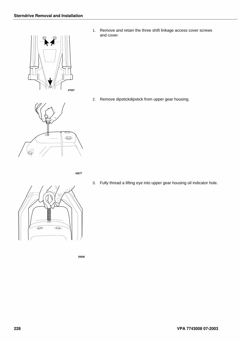
Sterndrive Removal and Installation
1. Remove and retain the three shift linkage access cover screws and cover.
2. Remove dipstickdipstick from upper gear housing.
3. Fully thread a lifting eye into upper gear housing oil indicator hole.
47557
43677
35056
228 VPA 7743008 07-2003
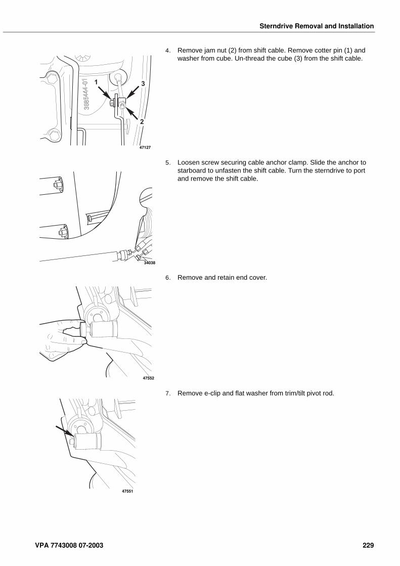
Sterndrive Removal and Installation
4. Remove jam nut (2) from shift cable. Remove cotter pin (1) and washer from cube. Un-thread the cube (3) from the shift cable.
5. Loosen screw securing cable anchor clamp. Slide the anchor to starboard to unfasten the shift cable. Turn the sterndrive to port and remove the shift cable.
6. Remove and retain end cover.
7. Remove e-clip and flat washer from trim/tilt pivot rod.
1
2
3
47127
34038
47552
47551
VPA 7743008 07-2003 229
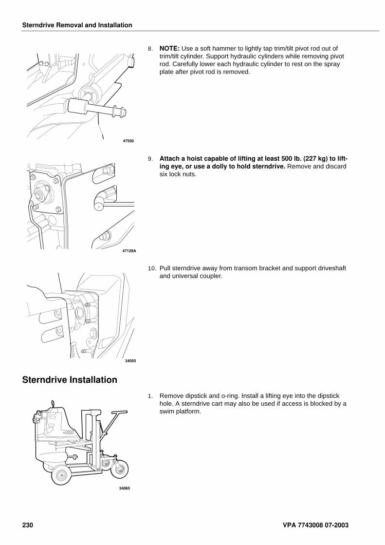
Sterndrive Removal and Installation
8. NOTE: Use a soft hammer to lightly tap trim/tilt pivot rod out of trim/tilt cylinder. Support hydraulic cylinders while removing pivot rod. Carefully lower each hydraulic cylinder to rest on the spray plate after pivot rod is removed.
9. Attach a hoist capable of lifting at least 500 lb. (227 kg) to lift-ing eye, or use a dolly to hold sterndrive. Remove and discard six lock nuts.
10. Pull sterndrive away from transom bracket and support driveshaft and universal coupler.
Sterndrive Installation
1. Remove dipstick and o-ring. Install a lifting eye into the dipstick hole. A sterndrive cart may also be used if access is blocked by a swim platform.
47550
47129A
34055
34065
230 VPA 7743008 07-2003
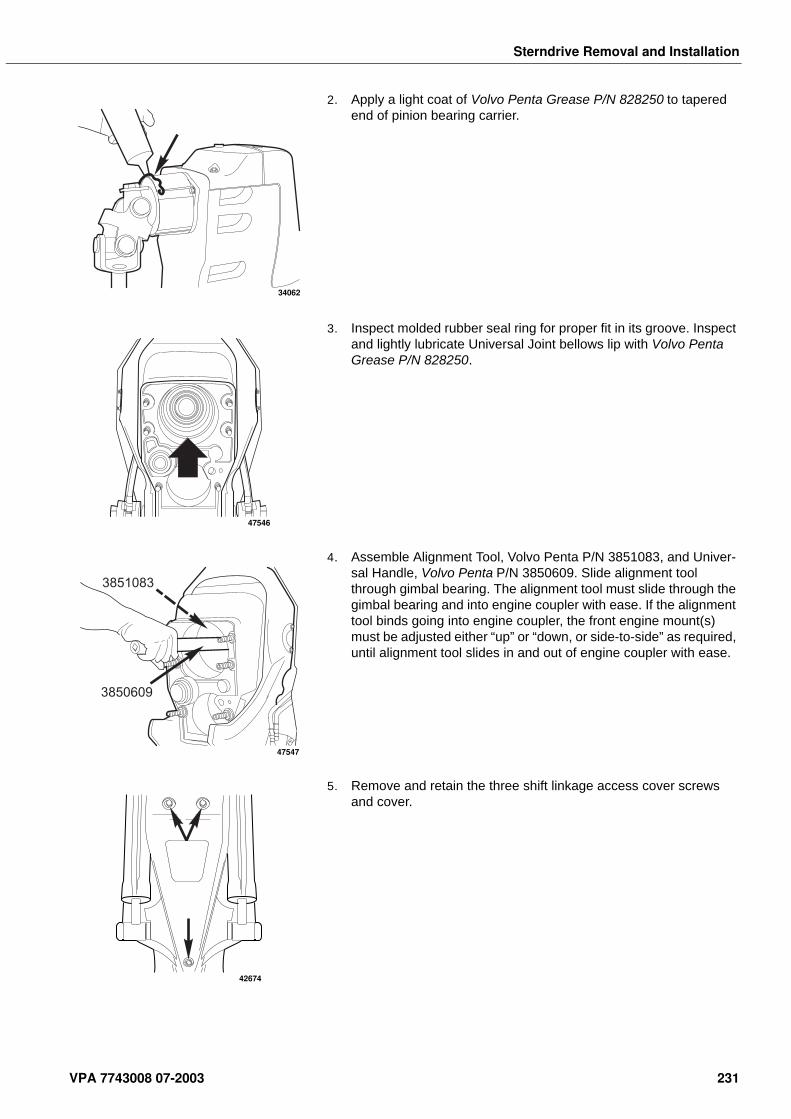
Sterndrive Removal and Installation
2. Apply a light coat of Volvo Penta Grease P/N 828250 to tapered end of pinion bearing carrier.
3. Inspect molded rubber seal ring for proper fit in its groove. Inspect and lightly lubricate Universal Joint bellows lip with Volvo Penta Grease P/N 828250.
4. Assemble Alignment Tool, Volvo Penta P/N 3851083, and Univer-sal Handle, Volvo Penta P/N 3850609. Slide alignment tool through gimbal bearing. The alignment tool must slide through the gimbal bearing and into engine coupler with ease. If the alignment tool binds going into engine coupler, the front engine mount(s) must be adjusted either “up” or “down, or side-to-side” as required, until alignment tool slides in and out of engine coupler with ease.
5. Remove and retain the three shift linkage access cover screws and cover.
34062
47546
3851083
3850609
47547
42674
VPA 7743008 07-2003 231
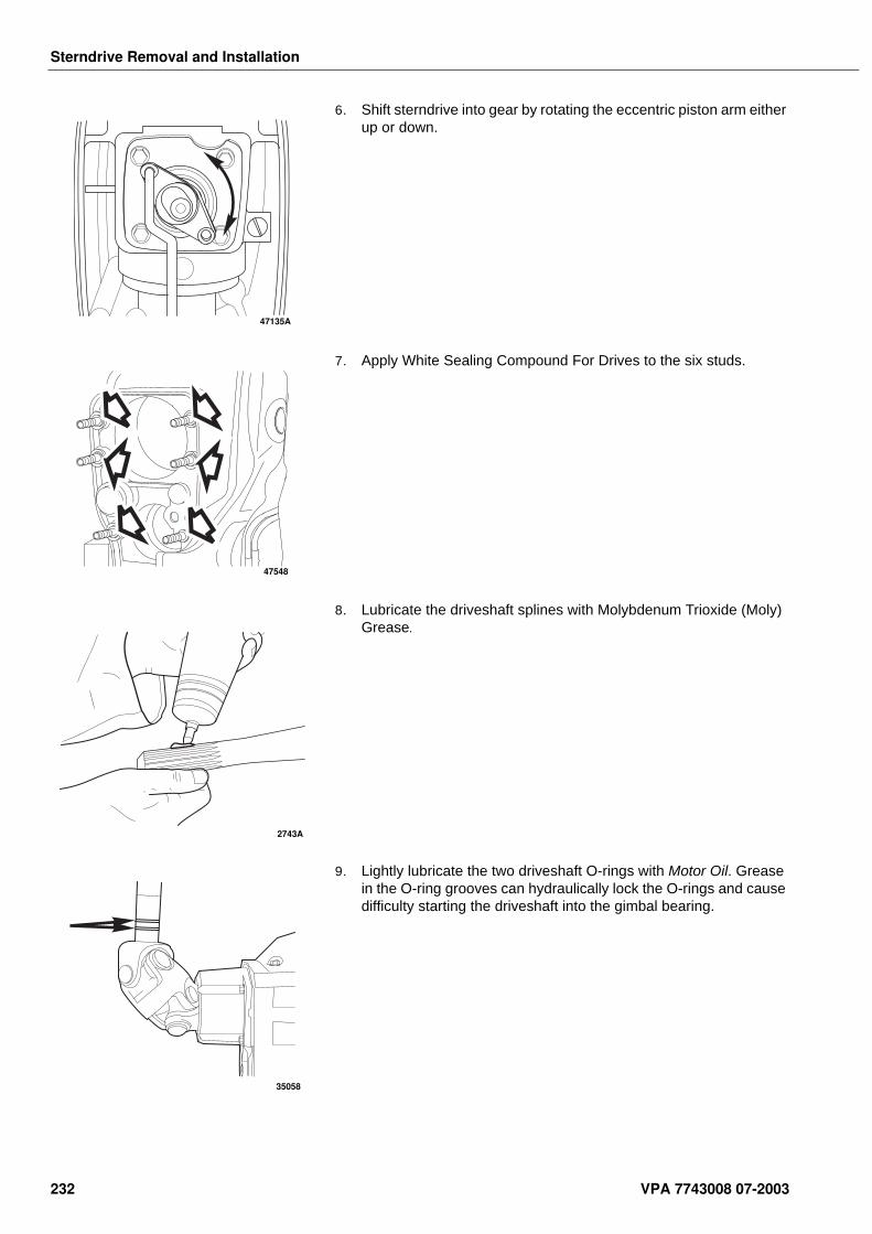
Sterndrive Removal and Installation
6. Shift sterndrive into gear by rotating the eccentric piston arm either up or down.
7. Apply White Sealing Compound For Drives to the six studs.
8. Lubricate the driveshaft splines with Molybdenum Trioxide (Moly) Grease.
9. Lightly lubricate the two driveshaft O-rings with Motor Oil. Grease in the O-ring grooves can hydraulically lock the O-rings and cause difficulty starting the driveshaft into the gimbal bearing.
47135A
47548
2743A
35058
232 VPA 7743008 07-2003
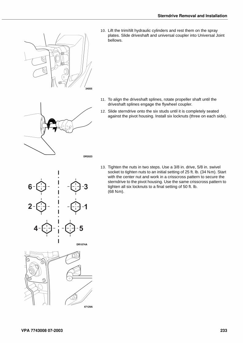
Sterndrive Removal and Installation
10. Lift the trim/tilt hydraulic cylinders and rest them on the spray plates. Slide driveshaft and universal coupler into Universal Joint bellows.
11. To align the driveshaft splines, rotate propeller shaft until the driveshaft splines engage the flywheel coupler.
12. Slide sterndrive onto the six studs until it is completely seated against the pivot housing. Install six locknuts (three on each side).
13. Tighten the nuts in two steps. Use a 3/8 in. drive, 5/8 in. swivel socket to tighten nuts to an initial setting of 25 ft. lb. (34 N•m). Start with the center nut and work in a crisscross pattern to secure the sterndrive to the pivot housing. Use the same crisscross pattern to tighten all six locknuts to a final setting of 50 ft. lb. (68 N•m).
34055
DR2023
12
36
4 5
DR1074A
47129A
VPA 7743008 07-2003 233
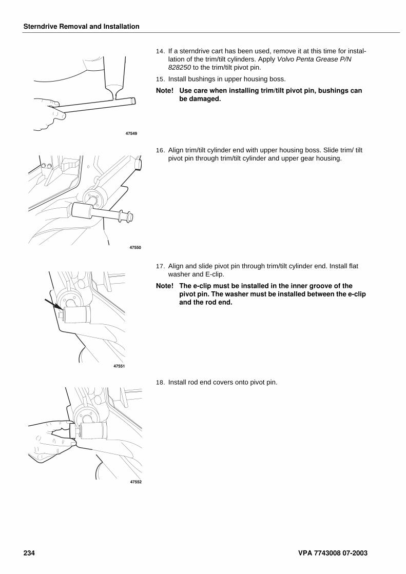
Sterndrive Removal and Installation
14. If a sterndrive cart has been used, remove it at this time for instal-lation of the trim/tilt cylinders. Apply Volvo Penta Grease P/N 828250 to the trim/tilt pivot pin.
15. Install bushings in upper housing boss.
Note! Use care when installing trim/tilt pivot pin, bushings can be damaged.
16. Align trim/tilt cylinder end with upper housing boss. Slide trim/ tilt pivot pin through trim/tilt cylinder and upper gear housing.
17. Align and slide pivot pin through trim/tilt cylinder end. Install flat washer and E-clip.
Note! The e-clip must be installed in the inner groove of the pivot pin. The washer must be installed between the e-clip and the rod end.
18. Install rod end covers onto pivot pin.
47549
47550
47551
47552
234 VPA 7743008 07-2003
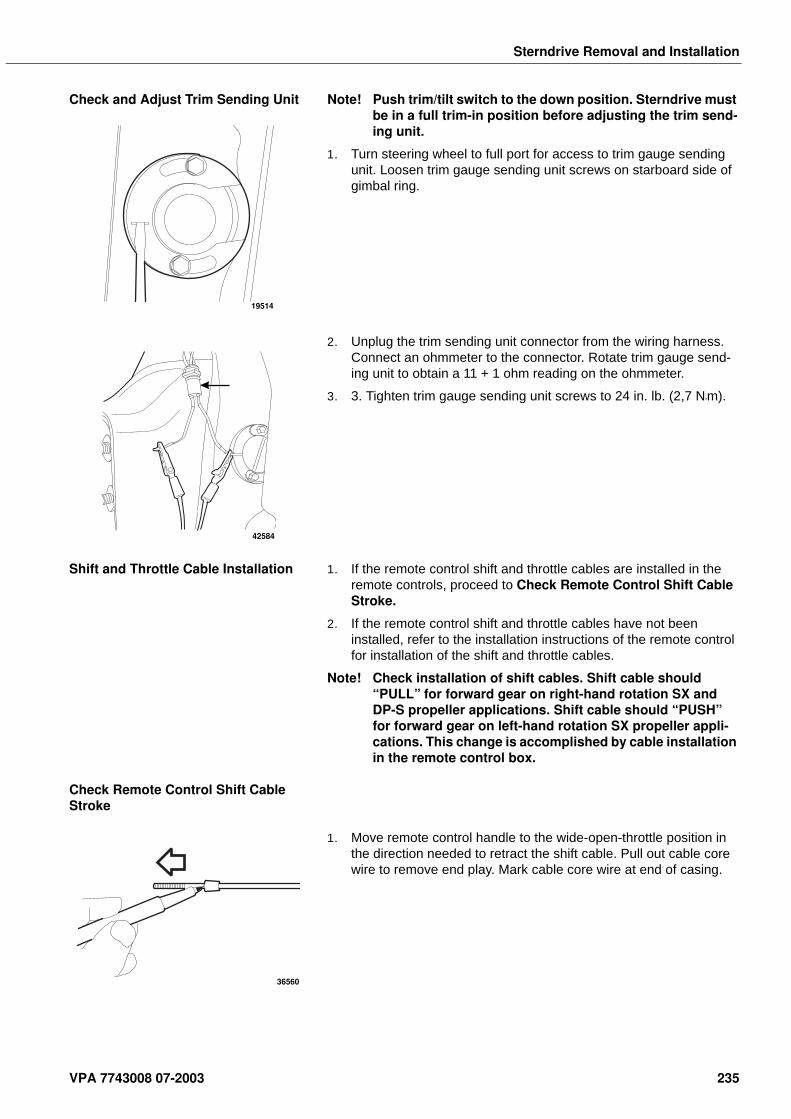
Sterndrive Removal and Installation
Check and Adjust Trim Sending Unit Note! Push trim/tilt switch to the down position. Sterndrive must be in a full trim-in position before adjusting the trim send-ing unit.
1. Turn steering wheel to full port for access to trim gauge sending unit. Loosen trim gauge sending unit screws on starboard side of gimbal ring.
2. Unplug the trim sending unit connector from the wiring harness. Connect an ohmmeter to the connector. Rotate trim gauge send-ing unit to obtain a 11 + 1 ohm reading on the ohmmeter.
3. 3. Tighten trim gauge sending unit screws to 24 in. lb. (2,7 N•m).
Shift and Throttle Cable Installation 1. If the remote control shift and throttle cables are installed in the remote controls, proceed to Check Remote Control Shift Cable Stroke.
2. If the remote control shift and throttle cables have not been installed, refer to the installation instructions of the remote control for installation of the shift and throttle cables.
Note! Check installation of shift cables. Shift cable should “PULL” for forward gear on right-hand rotation SX and DP-S propeller applications. Shift cable should “PUSH” for forward gear on left-hand rotation SX propeller appli-cations. This change is accomplished by cable installation in the remote control box.
Check Remote Control Shift Cable Stroke
1. Move remote control handle to the wide-open-throttle position in the direction needed to retract the shift cable. Pull out cable core wire to remove end play. Mark cable core wire at end of casing.
19514
42584
36560
VPA 7743008 07-2003 235
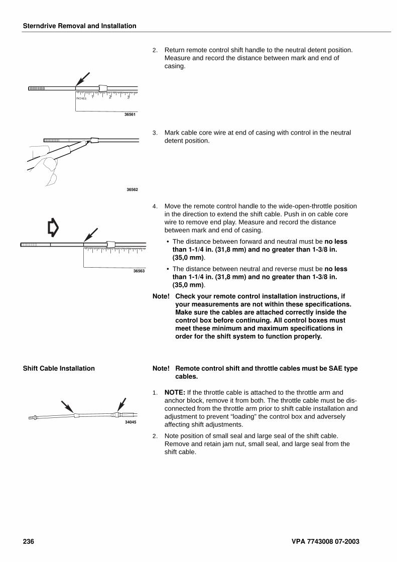
Sterndrive Removal and Installation
2. Return remote control shift handle to the neutral detent position. Measure and record the distance between mark and end of casing.
3. Mark cable core wire at end of casing with control in the neutral detent position.
4. Move the remote control handle to the wide-open-throttle position in the direction to extend the shift cable. Push in on cable core wire to remove end play. Measure and record the distance between mark and end of casing.
• The distance between forward and neutral must be no less than 1-1/4 in. (31,8 mm) and no greater than 1-3/8 in. (35,0 mm).
• The distance between neutral and reverse must be no less than 1-1/4 in. (31,8 mm) and no greater than 1-3/8 in. (35,0 mm).
Note! Check your remote control installation instructions, if your measurements are not within these specifications. Make sure the cables are attached correctly inside the control box before continuing. All control boxes must meet these minimum and maximum specifications in order for the shift system to function properly.
Shift Cable Installation Note! Remote control shift and throttle cables must be SAE type cables.
1. NOTE: If the throttle cable is attached to the throttle arm and anchor block, remove it from both. The throttle cable must be dis-connected from the throttle arm prior to shift cable installation and adjustment to prevent “loading” the control box and adversely affecting shift adjustments.
2. Note position of small seal and large seal of the shift cable. Remove and retain jam nut, small seal, and large seal from the shift cable.
INCHES1 2 3
36561
36562
36563
34045
236 VPA 7743008 07-2003
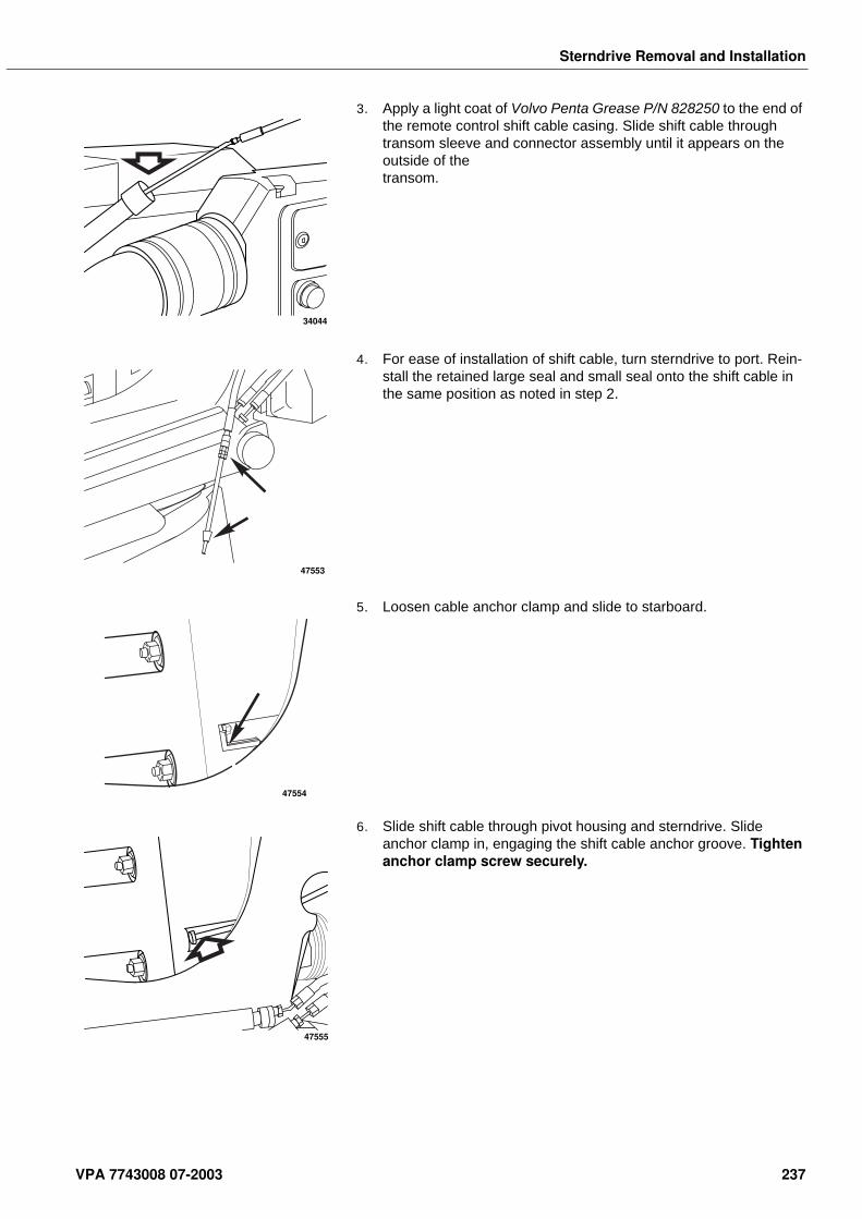
Sterndrive Removal and Installation
3. Apply a light coat of Volvo Penta Grease P/N 828250 to the end of the remote control shift cable casing. Slide shift cable through transom sleeve and connector assembly until it appears on the outside of the transom.
4. For ease of installation of shift cable, turn sterndrive to port. Rein-stall the retained large seal and small seal onto the shift cable in the same position as noted in step 2.
5. Loosen cable anchor clamp and slide to starboard.
6. Slide shift cable through pivot housing and sterndrive. Slide anchor clamp in, engaging the shift cable anchor groove. Tighten anchor clamp screw securely.
34044
47553
47554
47555
VPA 7743008 07-2003 237
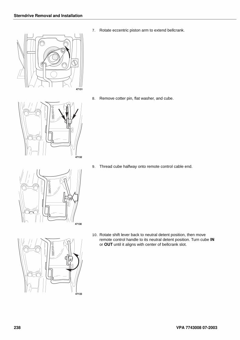
Sterndrive Removal and Installation
7. Rotate eccentric piston arm to extend bellcrank.
8. Remove cotter pin, flat washer, and cube.
9. Thread cube halfway onto remote control cable end.
10. Rotate shift lever back to neutral detent position, then move remote control handle to its neutral detent position. Turn cube IN or OUT until it aligns with center of bellcrank slot.
47131
47132
47130
47133
238 VPA 7743008 07-2003
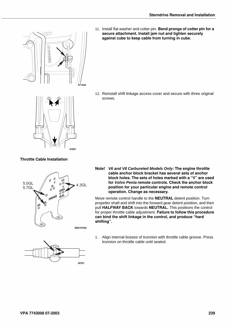
Sterndrive Removal and Installation
11. Install flat washer and cotter pin. Bend prongs of cotter pin for a secure attachment. Install jam nut and tighten securely against cube to keep cable from turning in cube.
12. Reinstall shift linkage access cover and secure with three original screws.
Throttle Cable Installation
Note! V6 and V8 Carbureted Models Only: The engine throttle cable anchor block bracket has several sets of anchor block holes. The sets of holes marked with a “V” are used for Volvo Penta remote controls. Check the anchor block position for your particular engine and remote control operation. Change as necessary.
Move remote control handle to the NEUTRAL detent position. Turn propeller shaft and shift into the forward gear detent position, and then pull HALFWAY BACK towards NEUTRAL. This positions the control for proper throttle cable adjustment. Failure to follow this procedure can bind the shift linkage in the control, and produce “hard shifting”.
1. Align internal bosses of trunnion with throttle cable groove. Press trunnion on throttle cable until seated.
47134A
47557
5.0GL5.7GL
4.3GL
DRC7279A
34751
VPA 7743008 07-2003 239
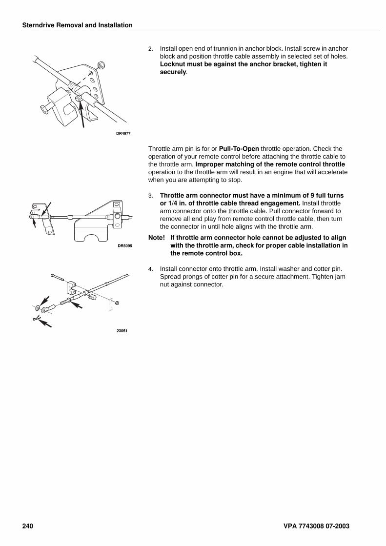
Sterndrive Removal and Installation
2. Install open end of trunnion in anchor block. Install screw in anchor block and position throttle cable assembly in selected set of holes. Locknut must be against the anchor bracket, tighten it securely.
Throttle arm pin is for or Pull-To-Open throttle operation. Check the operation of your remote control before attaching the throttle cable to the throttle arm. Improper matching of the remote control throttle operation to the throttle arm will result in an engine that will accelerate when you are attempting to stop.
3. Throttle arm connector must have a minimum of 9 full turns or 1/4 in. of throttle cable thread engagement. Install throttle arm connector onto the throttle cable. Pull connector forward to remove all end play from remote control throttle cable, then turn the connector in until hole aligns with the throttle arm.
Note! If throttle arm connector hole cannot be adjusted to align with the throttle arm, check for proper cable installation in the remote control box.
4. Install connector onto throttle arm. Install washer and cotter pin. Spread prongs of cotter pin for a secure attachment. Tighten jam nut against connector.
DR4977
DR5095
23051
240 VPA 7743008 07-2003
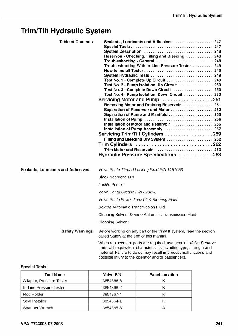
Trim/Tilt Hydraulic System
Trim/Tilt Hydraulic SystemTable of Contents Sealants, Lubricants and Adhesives . . . . . . . . . . . . . . . . . 247
Special Tools . . . . . . . . . . . . . . . . . . . . . . . . . . . . . . . . . . . . . 247System Description . . . . . . . . . . . . . . . . . . . . . . . . . . . . . . . 248Reservoir - Checking, Filling and Bleeding . . . . . . . . . . . . 248Troubleshooting - General . . . . . . . . . . . . . . . . . . . . . . . . . . 248Troubleshooting With In-Line Pressure Tester . . . . . . . . . 249How to Install Tester . . . . . . . . . . . . . . . . . . . . . . . . . . . . . . . 249System Hydraulic Tests . . . . . . . . . . . . . . . . . . . . . . . . . . . . 249Test No. 1 - Complete Up Circuit . . . . . . . . . . . . . . . . . . . . . 249Test No. 2 - Pump Isolation, Up Circuit . . . . . . . . . . . . . . . 250Test No. 3 - Complete Down Circuit . . . . . . . . . . . . . . . . . . 250Test No. 4 - Pump Isolation, Down Circuit . . . . . . . . . . . . . 250
Servicing Motor and Pump . . . . . . . . . . . . . . . . . . . 251Removing Motor and Draining Reservoir . . . . . . . . . . . . . . 251Separation of Reservoir and Motor . . . . . . . . . . . . . . . . . . . 252Separation of Pump and Manifold . . . . . . . . . . . . . . . . . . . . 255Installation of Pump . . . . . . . . . . . . . . . . . . . . . . . . . . . . . . . 256Installation of Motor and Reservoir . . . . . . . . . . . . . . . . . . 256Installation of Pump Assembly . . . . . . . . . . . . . . . . . . . . . . 257
Servicing Trim/Tilt Cylinders . . . . . . . . . . . . . . . . . . 259Filling and Bleeding Dry System . . . . . . . . . . . . . . . . . . . . . 262
Trim Cylinders . . . . . . . . . . . . . . . . . . . . . . . . . . . . . 262Trim Motor and Reservoir . . . . . . . . . . . . . . . . . . . . . . . . . . 263
Hydraulic Pressure Specifications . . . . . . . . . . . . . 263
Sealants, Lubricants and Adhesives Volvo Penta Thread Locking Fluid P/N 1161053
Black Neoprene Dip
Loctite Primer
Volvo Penta Grease P/N 828250
Volvo Penta Power Trim/Tilt & Steering Fluid
Dexron Automatic Transmission Fluid
Cleaning Solvent Dexron Automatic Transmission Fluid
Cleaning Solvent
Safety Warnings Before working on any part of the trim/tilt system, read the section called Safety at the end of this manual.
When replacement parts are required, use genuine Volvo Penta or parts with equivalent characteristics including type, strength and material. Failure to do so may result in product malfunctions and possible injury to the operator and/or passengers.
Special Tools
Tool Name Volvo P/N Panel Location
Adaptor, Pressure Tester 3854366-6 K
In-Line Pressure Tester 3854368-2 K
Rod Holder 3854367-4 K
Seal Installer 3854364-1 K
Spanner Wrench 3854365-8 A
VPA 7743008 07-2003 241
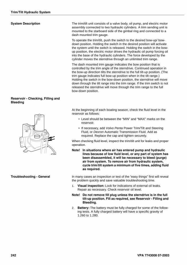
Trim/Tilt Hydraulic System
System Description The trim/tilt unit consists of a valve body, oil pump, and electric motor assembly connected to two hydraulic cylinders. A trim sending unit is mounted to the starboard side of the gimbal ring and connected to a dash mounted trim gauge.
To operate the trim/tilt, push the switch to the desired bow-up/ bow- down position. Holding the switch in the desired position will activate the system until the switch is released. Holding the switch in the bow-up position, the electric motor drives the hydraulic oil pump forcing oil into the base of the hydraulic cylinders. The force developed by the cylinder moves the sterndrive through an unlimited trim range.
The dash mounted trim gauge indicates the bow position that is controlled by the trim angle of the sterndrive. Continued operation in the bow-up direction tilts the sterndrive to the full tilt-up position. (The trim gauge indicates full bow-up position when in the tilt range.) Holding the switch in the bow-down position, the sterndrive will move down through the tilt range into the trim range. If the trim switch is not released the sterndrive will move through the trim range to the full bow-down position.
Reservoir - Checking, Filling and Bleeding
At the beginning of each boating season, check the fluid level in the reservoir as follows:
• Level should be between the “MIN” and “MAX” marks on the reservoir.
• If necessary, add Volvo Penta Power Trim/Tilt and Steering Fluid, or Dexron Automatic Transmission Fluid. Add as required. Replace the cap and tighten securely.
When checking fluid level, inspect the trim/tilt unit for leaks and proper operation.
Note! In situations where air has entered pump and hydraulic lines because of low fluid level, or any part of system has been disassembled, it will be necessary to bleed (purge) air from system. To remove air from hydraulic system, cycle trim/tilt system a minimum of five times, adding fluid as required.
Troubleshooting - General In many cases an inspection or test of the “easy things” first will reveal the problem quickly and save valuable troubleshooting time.
1. Visual inspection: Look for indications of external oil leaks. Repair as necessary. Check reservoir oil level.
Note! Do not remove fill plug unless the sterndrive is in the full tilt-up position. Fill as required, see Reservoir - Filling and Bleeding.
2. Battery: The battery must be fully charged for some of the follow-ing tests. A fully charged battery will have a specific gravity of 1.260 to 1.280.
MAX
MIN
47564
242 VPA 7743008 07-2003
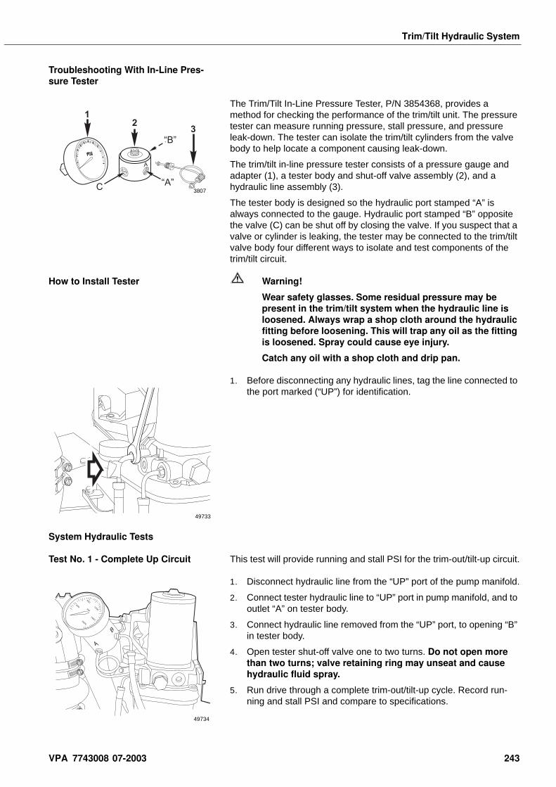
Trim/Tilt Hydraulic System
Troubleshooting With In-Line Pres-sure Tester
The Trim/Tilt In-Line Pressure Tester, P/N 3854368, provides a method for checking the performance of the trim/tilt unit. The pressure tester can measure running pressure, stall pressure, and pressure leak-down. The tester can isolate the trim/tilt cylinders from the valve body to help locate a component causing leak-down.
The trim/tilt in-line pressure tester consists of a pressure gauge and adapter (1), a tester body and shut-off valve assembly (2), and a hydraulic line assembly (3).
The tester body is designed so the hydraulic port stamped “A” is always connected to the gauge. Hydraulic port stamped “B” opposite the valve (C) can be shut off by closing the valve. If you suspect that a valve or cylinder is leaking, the tester may be connected to the trim/tilt valve body four different ways to isolate and test components of the trim/tilt circuit.
How to Install Tester Warning!
Wear safety glasses. Some residual pressure may be present in the trim/tilt system when the hydraulic line is loosened. Always wrap a shop cloth around the hydraulic fitting before loosening. This will trap any oil as the fitting is loosened. Spray could cause eye injury.
Catch any oil with a shop cloth and drip pan.
1. Before disconnecting any hydraulic lines, tag the line connected to the port marked (“UP”) for identification.
System Hydraulic Tests
Test No. 1 - Complete Up Circuit This test will provide running and stall PSI for the trim-out/tilt-up circuit.
1. Disconnect hydraulic line from the “UP” port of the pump manifold.
2. Connect tester hydraulic line to “UP” port in pump manifold, and to outlet “A” on tester body.
3. Connect hydraulic line removed from the “UP” port, to opening “B” in tester body.
4. Open tester shut-off valve one to two turns. Do not open more than two turns; valve retaining ring may unseat and cause hydraulic fluid spray.
5. Run drive through a complete trim-out/tilt-up cycle. Record run-ning and stall PSI and compare to specifications.
12
3
A
“B”
“A”C 3807
49733
400psi
800
1200
16002000
A
B
49734
VPA 7743008 07-2003 243
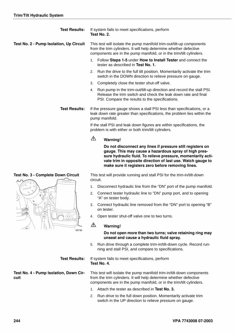
Trim/Tilt Hydraulic System
Test Results: If system fails to meet specifications, perform Test No. 2.
Test No. 2 - Pump Isolation, Up Circuit This test will isolate the pump manifold trim-out/tilt-up components from the trim cylinders. It will help determine whether defective components are in the pump manifold, or in the trim/tilt cylinders.
1. Follow Steps 1-5 under How to Install Tester and connect the tester as described in Test No. 1.
2. Run the drive to the full tilt position. Momentarily activate the trim switch in the DOWN direction to relieve pressure on gauge.
3. Completely close the tester shut-off valve.
4. Run pump in the trim-out/tilt-up direction and record the stall PSI. Release the trim switch and check the leak down rate and final PSI. Compare the results to the specifications.
Test Results: If the pressure gauge shows a stall PSI less than specifications, or a leak down rate greater than specifications, the problem lies within the pump manifold.
If the stall PSI and leak down figures are within specifications, the problem is with either or both trim/tilt cylinders.
Warning!
Do not disconnect any lines if pressure still registers on gauge. This may cause a hazardous spray of high pres-sure hydraulic fluid. To relieve pressure, momentarily acti-vate trim in opposite direction of last use. Watch gauge to make sure it registers zero before removing lines.
Test No. 3 - Complete Down Circuit This test will provide running and stall PSI for the trim-in/tilt-down circuit.
1. Disconnect hydraulic line from the “DN” port of the pump manifold.
2. Connect tester hydraulic line to ”DN” pump port, and to opening “A” on tester body.
3. Connect hydraulic line removed from the “DN” port to opening “B” on tester.
4. Open tester shut-off valve one to two turns.
Warning!
Do not open more than two turns; valve retaining ring may unseat and cause a hydraulic fluid spray.
5. Run drive through a complete trim-in/tilt-down cycle. Record run-ning and stall PSI, and compare to specifications.
Test Results: If system fails to meet specifications, perform Test No. 4.
Test No. 4 - Pump Isolation, Down Cir-cuit
This test will isolate the pump manifold trim-in/tilt-down components from the trim cylinders. It will help determine whether defective components are in the pump manifold, or in the trim/tilt cylinders.
1. Attach the tester as described in Test No. 3.
2. Run drive to the full down position. Momentarily activate trim switch in the UP direction to relieve pressure on gauge.
400psi
800
1200
16002000
A
B
49736
244 VPA 7743008 07-2003
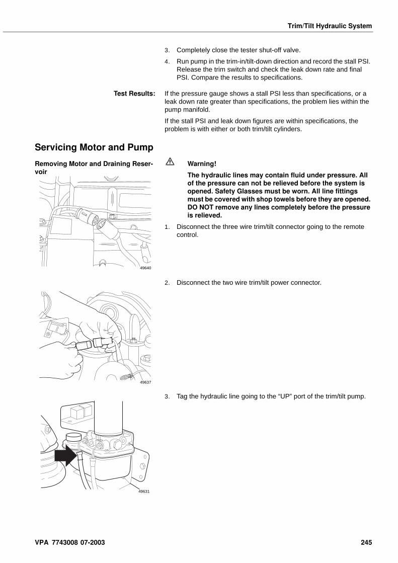
Trim/Tilt Hydraulic System
3. Completely close the tester shut-off valve.
4. Run pump in the trim-in/tilt-down direction and record the stall PSI. Release the trim switch and check the leak down rate and final PSI. Compare the results to specifications.
Test Results: If the pressure gauge shows a stall PSI less than specifications, or a leak down rate greater than specifications, the problem lies within the pump manifold.
If the stall PSI and leak down figures are within specifications, the problem is with either or both trim/tilt cylinders.
Servicing Motor and Pump
Removing Motor and Draining Reser-voir
Warning!
The hydraulic lines may contain fluid under pressure. All of the pressure can not be relieved before the system is opened. Safety Glasses must be worn. All line fittings must be covered with shop towels before they are opened. DO NOT remove any lines completely before the pressure is relieved.
1. Disconnect the three wire trim/tilt connector going to the remote control.
2. Disconnect the two wire trim/tilt power connector.
3. Tag the hydraulic line going to the “UP” port of the trim/tilt pump.
49640
49637
49631
VPA 7743008 07-2003 245
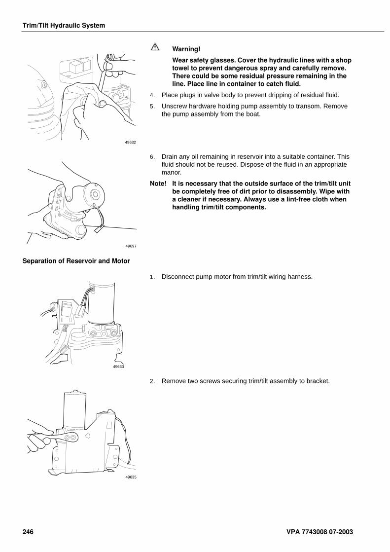
Trim/Tilt Hydraulic System
Warning!
Wear safety glasses. Cover the hydraulic lines with a shop towel to prevent dangerous spray and carefully remove. There could be some residual pressure remaining in the line. Place line in container to catch fluid.
4. Place plugs in valve body to prevent dripping of residual fluid.
5. Unscrew hardware holding pump assembly to transom. Remove the pump assembly from the boat.
6. Drain any oil remaining in reservoir into a suitable container. This fluid should not be reused. Dispose of the fluid in an appropriate manor.
Note! It is necessary that the outside surface of the trim/tilt unit be completely free of dirt prior to disassembly. Wipe with a cleaner if necessary. Always use a lint-free cloth when handling trim/tilt components.
Separation of Reservoir and Motor
1. Disconnect pump motor from trim/tilt wiring harness.
2. Remove two screws securing trim/tilt assembly to bracket.
49632
49697
49633
49635
246 VPA 7743008 07-2003
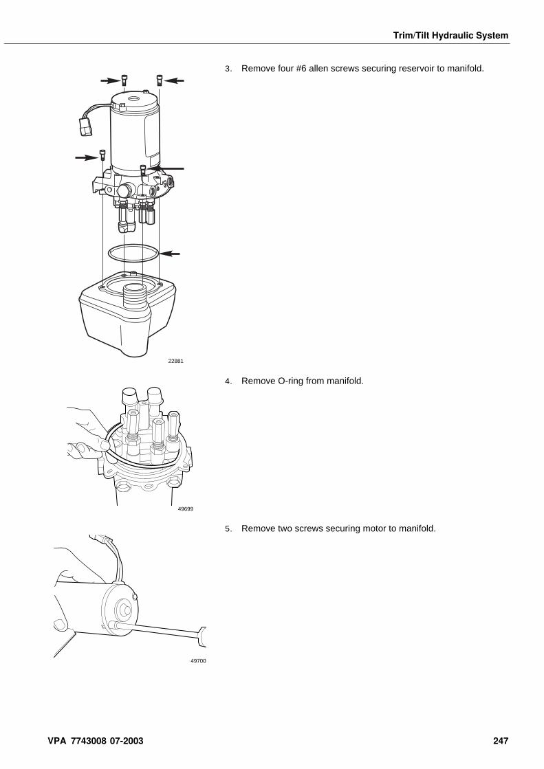
Trim/Tilt Hydraulic System
3. Remove four #6 allen screws securing reservoir to manifold.
4. Remove O-ring from manifold.
5. Remove two screws securing motor to manifold.
22881
49699
49700
VPA 7743008 07-2003 247
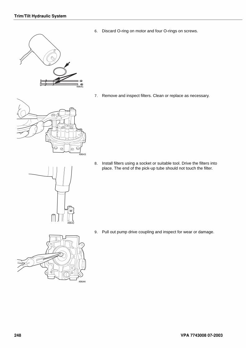
Trim/Tilt Hydraulic System
6. Discard O-ring on motor and four O-rings on screws.
7. Remove and inspect filters. Clean or replace as necessary.
8. Install filters using a socket or suitable tool. Drive the filters into place. The end of the pick-up tube should not touch the filter.
9. Pull out pump drive coupling and inspect for wear or damage.
49641
49643
49642
49644
248 VPA 7743008 07-2003
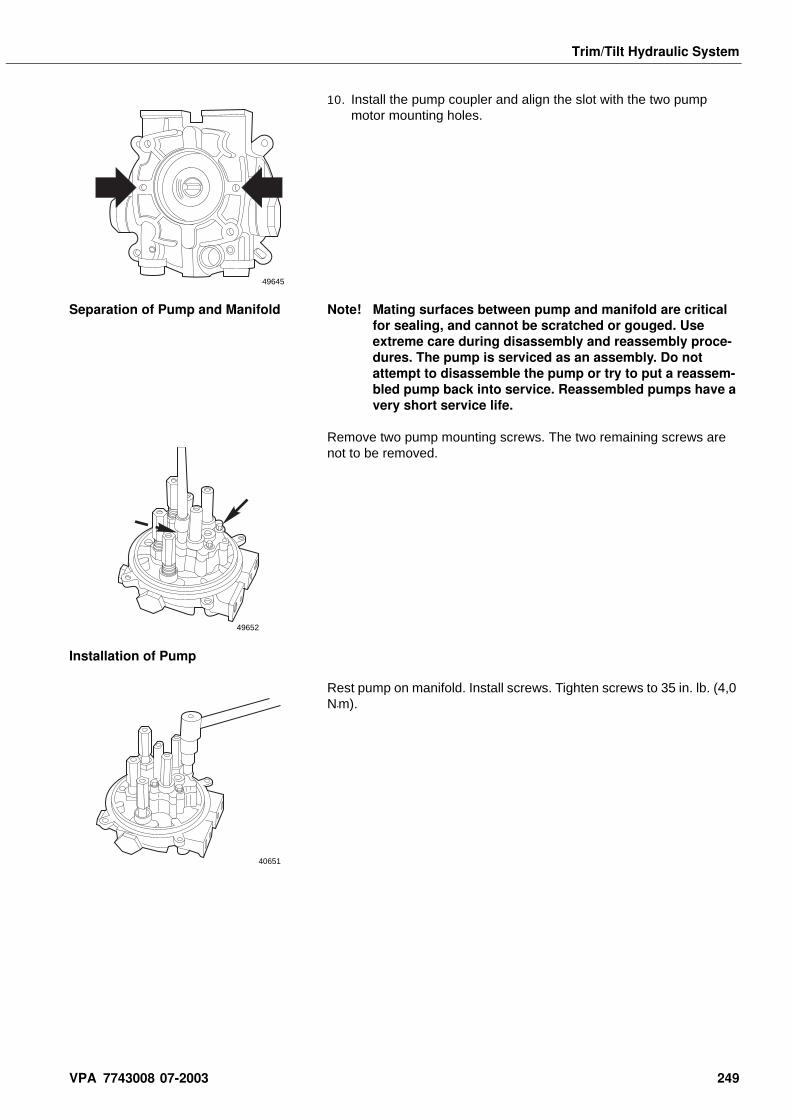
Trim/Tilt Hydraulic System
10. Install the pump coupler and align the slot with the two pump motor mounting holes.
Separation of Pump and Manifold Note! Mating surfaces between pump and manifold are critical for sealing, and cannot be scratched or gouged. Use extreme care during disassembly and reassembly proce-dures. The pump is serviced as an assembly. Do not attempt to disassemble the pump or try to put a reassem-bled pump back into service. Reassembled pumps have a very short service life.
Remove two pump mounting screws. The two remaining screws are not to be removed.
Installation of Pump
Rest pump on manifold. Install screws. Tighten screws to 35 in. lb. (4,0 N•m).
49645
49652
40651
VPA 7743008 07-2003 249
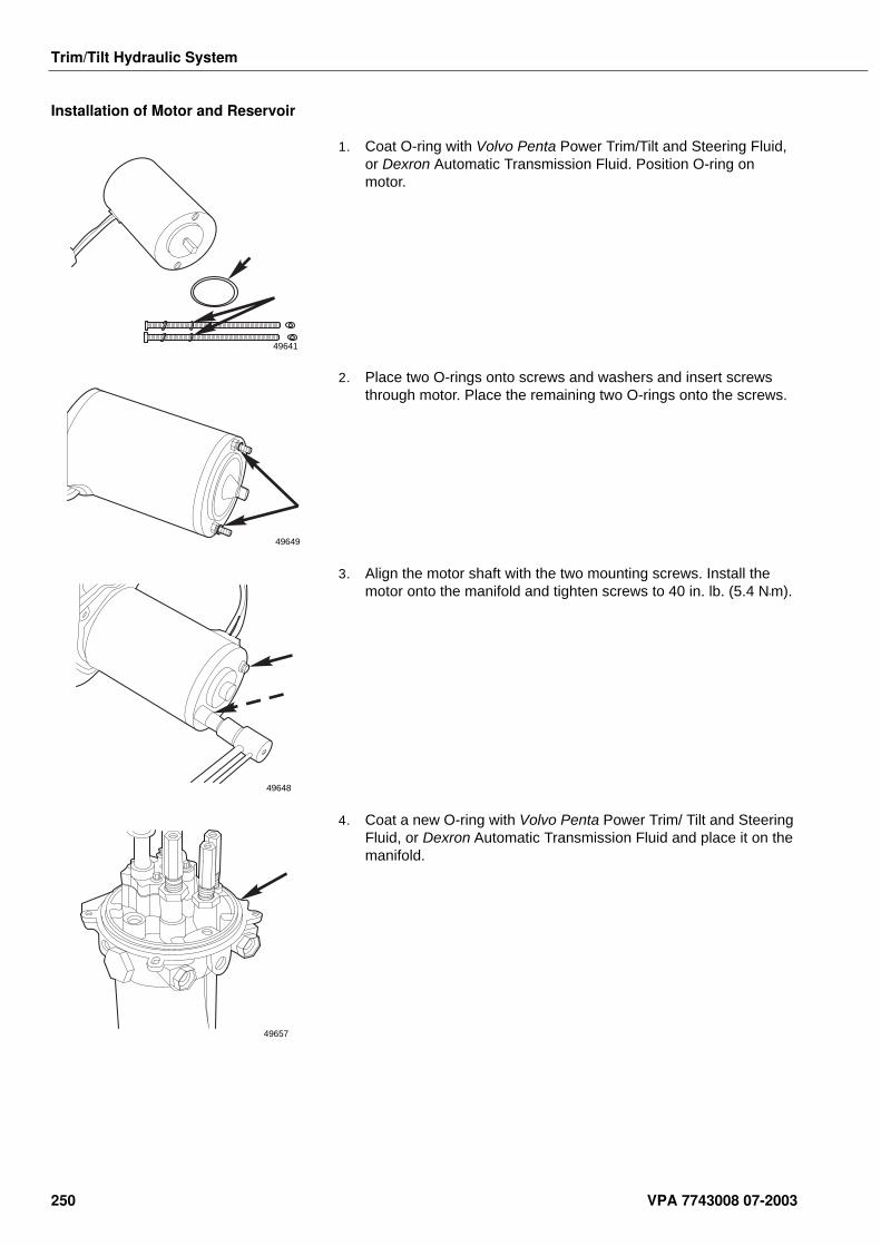
Trim/Tilt Hydraulic System
Installation of Motor and Reservoir
1. Coat O-ring with Volvo Penta Power Trim/Tilt and Steering Fluid, or Dexron Automatic Transmission Fluid. Position O-ring on motor.
2. Place two O-rings onto screws and washers and insert screws through motor. Place the remaining two O-rings onto the screws.
3. Align the motor shaft with the two mounting screws. Install the motor onto the manifold and tighten screws to 40 in. lb. (5.4 N•m).
4. Coat a new O-ring with Volvo Penta Power Trim/ Tilt and Steering Fluid, or Dexron Automatic Transmission Fluid and place it on the manifold.
49641
49649
49648
49657
250 VPA 7743008 07-2003
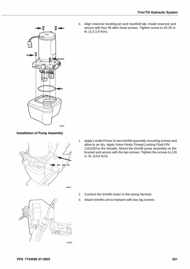
Trim/Tilt Hydraulic System
5. Align reservoir locating pin and manifold tab. Install reservoir and secure with four #6 allen head screws. Tighten screw to 20-25 in. lb. (2,2-2,8 N•m).
Installation of Pump Assembly
1. Apply Loctite Primer to two trim/tilt assembly mounting screws and allow to air dry. Apply Volvo Penta Thread Locking Fluid P/N 1161053 to the threads. Mount the trim/tilt pump assembly on the bracket and secure with the two screws. Tighten the screws to 120 in. lb. (13,6 N•m).
2. Connect the trim/tilt motor to the wiring harness.
3. Attach trim/tilt unit to transom with two lag screws.
22881
49654
49653
VPA 7743008 07-2003 251
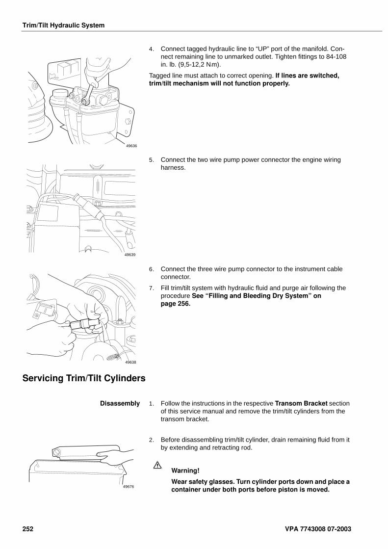
Trim/Tilt Hydraulic System
4. Connect tagged hydraulic line to “UP” port of the manifold. Con-nect remaining line to unmarked outlet. Tighten fittings to 84-108 in. lb. (9,5-12,2 N•m).
Tagged line must attach to correct opening. If lines are switched, trim/tilt mechanism will not function properly.
5. Connect the two wire pump power connector the engine wiring harness.
6. Connect the three wire pump connector to the instrument cable connector.
7. Fill trim/tilt system with hydraulic fluid and purge air following the procedure See “Filling and Bleeding Dry System” on page 256.
Servicing Trim/Tilt Cylinders
Disassembly 1. Follow the instructions in the respective Transom Bracket section of this service manual and remove the trim/tilt cylinders from the transom bracket.
2. Before disassembling trim/tilt cylinder, drain remaining fluid from it by extending and retracting rod.
Warning!
Wear safety glasses. Turn cylinder ports down and place a container under both ports before piston is moved.
49636
49639
49638
49676
252 VPA 7743008 07-2003
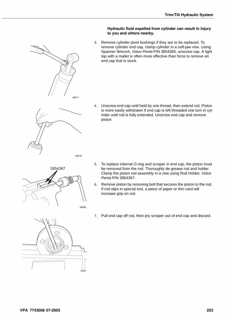
Trim/Tilt Hydraulic System
Hydraulic fluid expelled from cylinder can result in injury to you and others nearby.
3. Remove cylinder pivot bushings if they are to be replaced. To remove cylinder end cap, clamp cylinder in a soft-jaw vise. Using Spanner Wrench, Volvo Penta P/N 3854365, unscrew cap. A light tap with a mallet is often more effective than force to remove an end cap that is stuck.
4. Unscrew end cap until held by one thread, then extend rod. Piston is more easily withdrawn if end cap is left threaded one turn in cyl-inder until rod is fully extended. Unscrew end cap and remove piston.
5. To replace internal O-ring and scraper in end cap, the piston must be removed from the rod. Thoroughly de-grease rod and holder. Clamp the piston rod assembly in a vise using Rod Holder, Volvo Penta P/N 3854367.
6. Remove piston by removing bolt that secures the piston to the rod. If rod slips in special tool, a piece of paper or thin card will increase grip on rod.
7. Pull end cap off rod, then pry scraper out of end cap and discard.
49677
49678
3854367
49680
6234
VPA 7743008 07-2003 253
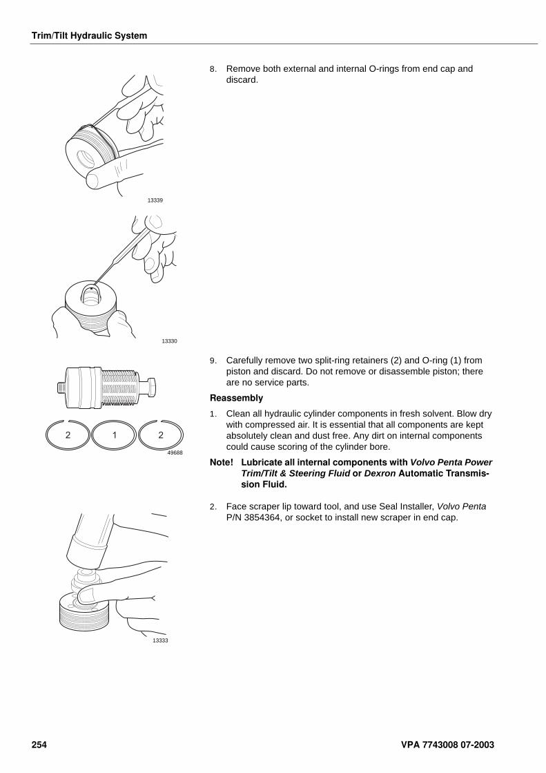
Trim/Tilt Hydraulic System
8. Remove both external and internal O-rings from end cap and discard.
9. Carefully remove two split-ring retainers (2) and O-ring (1) from piston and discard. Do not remove or disassemble piston; there are no service parts.
Reassembly
1. Clean all hydraulic cylinder components in fresh solvent. Blow dry with compressed air. It is essential that all components are kept absolutely clean and dust free. Any dirt on internal components could cause scoring of the cylinder bore.
Note! Lubricate all internal components with Volvo Penta Power Trim/Tilt & Steering Fluid or Dexron Automatic Transmis-sion Fluid.
2. Face scraper lip toward tool, and use Seal Installer, Volvo Penta P/N 3854364, or socket to install new scraper in end cap.
13339
13330
2 21
49688
13333
254 VPA 7743008 07-2003
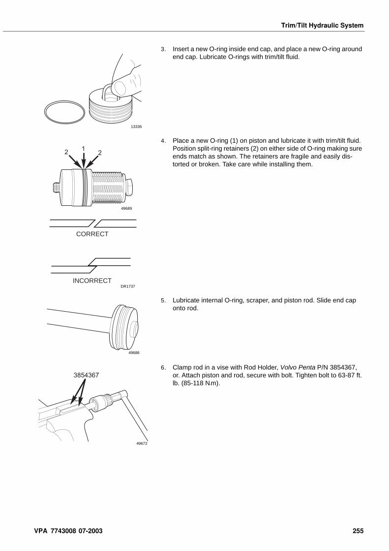
Trim/Tilt Hydraulic System
3. Insert a new O-ring inside end cap, and place a new O-ring around end cap. Lubricate O-rings with trim/tilt fluid.
4. Place a new O-ring (1) on piston and lubricate it with trim/tilt fluid. Position split-ring retainers (2) on either side of O-ring making sure ends match as shown. The retainers are fragile and easily dis-torted or broken. Take care while installing them.
5. Lubricate internal O-ring, scraper, and piston rod. Slide end cap onto rod.
6. Clamp rod in a vise with Rod Holder, Volvo Penta P/N 3854367, or. Attach piston and rod, secure with bolt. Tighten bolt to 63-87 ft. lb. (85-118 N•m).
13336
122
49689
CORRECT
INCORRECTDR1737
49686
3854367
49672
VPA 7743008 07-2003 255
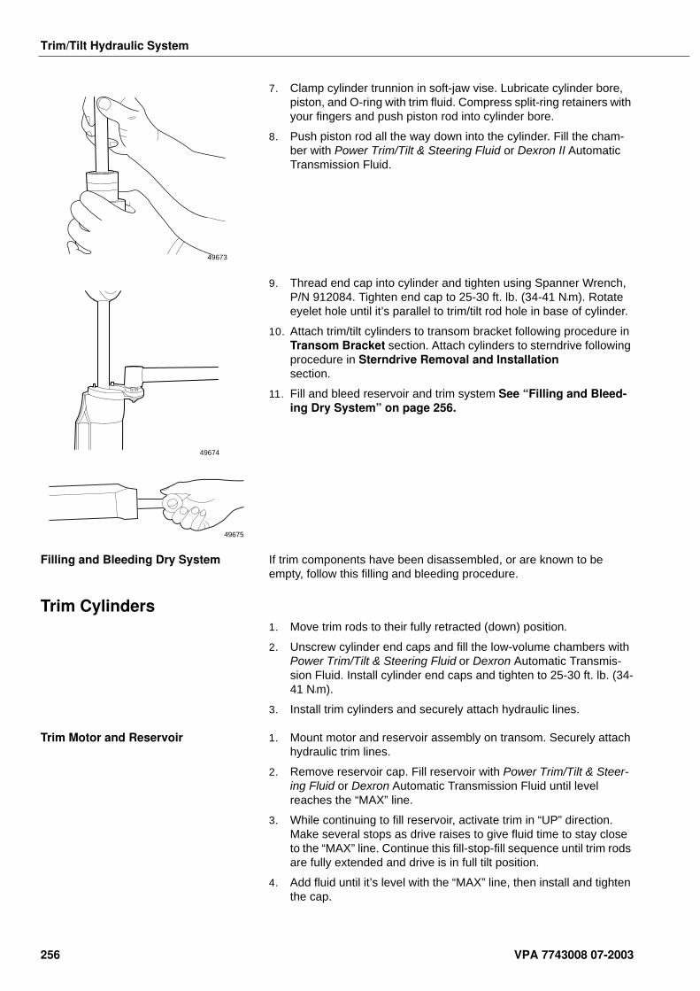
Trim/Tilt Hydraulic System
7. Clamp cylinder trunnion in soft-jaw vise. Lubricate cylinder bore, piston, and O-ring with trim fluid. Compress split-ring retainers with your fingers and push piston rod into cylinder bore.
8. Push piston rod all the way down into the cylinder. Fill the cham-ber with Power Trim/Tilt & Steering Fluid or Dexron II Automatic Transmission Fluid.
9. Thread end cap into cylinder and tighten using Spanner Wrench, P/N 912084. Tighten end cap to 25-30 ft. lb. (34-41 N•m). Rotate eyelet hole until it’s parallel to trim/tilt rod hole in base of cylinder.
10. Attach trim/tilt cylinders to transom bracket following procedure in Transom Bracket section. Attach cylinders to sterndrive following procedure in Sterndrive Removal and Installation section.
11. Fill and bleed reservoir and trim system See “Filling and Bleed-ing Dry System” on page 256.
Filling and Bleeding Dry System If trim components have been disassembled, or are known to be empty, follow this filling and bleeding procedure.
Trim Cylinders1. Move trim rods to their fully retracted (down) position.
2. Unscrew cylinder end caps and fill the low-volume chambers with Power Trim/Tilt & Steering Fluid or Dexron Automatic Transmis-sion Fluid. Install cylinder end caps and tighten to 25-30 ft. lb. (34-41 N•m).
3. Install trim cylinders and securely attach hydraulic lines.
Trim Motor and Reservoir 1. Mount motor and reservoir assembly on transom. Securely attach hydraulic trim lines.
2. Remove reservoir cap. Fill reservoir with Power Trim/Tilt & Steer-ing Fluid or Dexron Automatic Transmission Fluid until level reaches the “MAX” line.
3. While continuing to fill reservoir, activate trim in “UP” direction. Make several stops as drive raises to give fluid time to stay close to the “MAX” line. Continue this fill-stop-fill sequence until trim rods are fully extended and drive is in full tilt position.
4. Add fluid until it’s level with the “MAX” line, then install and tighten the cap.
49673
49674
49675
256 VPA 7743008 07-2003
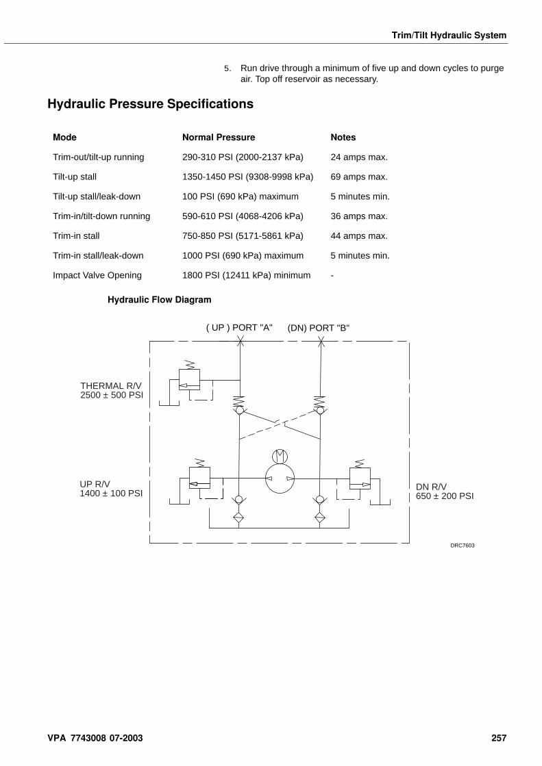
Trim/Tilt Hydraulic System
5. Run drive through a minimum of five up and down cycles to purge air. Top off reservoir as necessary.
Hydraulic Pressure Specifications
Hydraulic Flow Diagram
Mode Normal Pressure Notes
Trim-out/tilt-up running 290-310 PSI (2000-2137 kPa) 24 amps max.
Tilt-up stall 1350-1450 PSI (9308-9998 kPa) 69 amps max.
Tilt-up stall/leak-down 100 PSI (690 kPa) maximum 5 minutes min.
Trim-in/tilt-down running 590-610 PSI (4068-4206 kPa) 36 amps max.
Trim-in stall 750-850 PSI (5171-5861 kPa) 44 amps max.
Trim-in stall/leak-down 1000 PSI (690 kPa) maximum 5 minutes min.
Impact Valve Opening 1800 PSI (12411 kPa) minimum -
( UP ) PORT "A"
DN R/V650 ± 200 PSI
UP R/V1400 ± 100 PSI
THERMAL R/V2500 ± 500 PSI
(DN) PORT "B"
DRC7603
VPA 7743008 07-2003 257

Notes . . . . . . . . . . . . . . . . . . . . . . . . . . . . . . . . . . . . . . . . . . . . . . . . . . . . . . . . . . . . . . . . . . . . . . . . . . .
. . . . . . . . . . . . . . . . . . . . . . . . . . . . . . . . . . . . . . . . . . . . . . . . . . . . . . . . . . . . . . . . . . . . . . . . . . .
. . . . . . . . . . . . . . . . . . . . . . . . . . . . . . . . . . . . . . . . . . . . . . . . . . . . . . . . . . . . . . . . . . . . . . . . . . .
. . . . . . . . . . . . . . . . . . . . . . . . . . . . . . . . . . . . . . . . . . . . . . . . . . . . . . . . . . . . . . . . . . . . . . . . . . .
. . . . . . . . . . . . . . . . . . . . . . . . . . . . . . . . . . . . . . . . . . . . . . . . . . . . . . . . . . . . . . . . . . . . . . . . . . .
. . . . . . . . . . . . . . . . . . . . . . . . . . . . . . . . . . . . . . . . . . . . . . . . . . . . . . . . . . . . . . . . . . . . . . . . . . .
. . . . . . . . . . . . . . . . . . . . . . . . . . . . . . . . . . . . . . . . . . . . . . . . . . . . . . . . . . . . . . . . . . . . . . . . . . .
. . . . . . . . . . . . . . . . . . . . . . . . . . . . . . . . . . . . . . . . . . . . . . . . . . . . . . . . . . . . . . . . . . . . . . . . . . .
. . . . . . . . . . . . . . . . . . . . . . . . . . . . . . . . . . . . . . . . . . . . . . . . . . . . . . . . . . . . . . . . . . . . . . . . . . .
. . . . . . . . . . . . . . . . . . . . . . . . . . . . . . . . . . . . . . . . . . . . . . . . . . . . . . . . . . . . . . . . . . . . . . . . . . .
. . . . . . . . . . . . . . . . . . . . . . . . . . . . . . . . . . . . . . . . . . . . . . . . . . . . . . . . . . . . . . . . . . . . . . . . . . .
. . . . . . . . . . . . . . . . . . . . . . . . . . . . . . . . . . . . . . . . . . . . . . . . . . . . . . . . . . . . . . . . . . . . . . . . . . .
. . . . . . . . . . . . . . . . . . . . . . . . . . . . . . . . . . . . . . . . . . . . . . . . . . . . . . . . . . . . . . . . . . . . . . . . . . .
. . . . . . . . . . . . . . . . . . . . . . . . . . . . . . . . . . . . . . . . . . . . . . . . . . . . . . . . . . . . . . . . . . . . . . . . . . .
. . . . . . . . . . . . . . . . . . . . . . . . . . . . . . . . . . . . . . . . . . . . . . . . . . . . . . . . . . . . . . . . . . . . . . . . . . .
. . . . . . . . . . . . . . . . . . . . . . . . . . . . . . . . . . . . . . . . . . . . . . . . . . . . . . . . . . . . . . . . . . . . . . . . . . .
. . . . . . . . . . . . . . . . . . . . . . . . . . . . . . . . . . . . . . . . . . . . . . . . . . . . . . . . . . . . . . . . . . . . . . . . . . .
. . . . . . . . . . . . . . . . . . . . . . . . . . . . . . . . . . . . . . . . . . . . . . . . . . . . . . . . . . . . . . . . . . . . . . . . . . .
. . . . . . . . . . . . . . . . . . . . . . . . . . . . . . . . . . . . . . . . . . . . . . . . . . . . . . . . . . . . . . . . . . . . . . . . . . .
. . . . . . . . . . . . . . . . . . . . . . . . . . . . . . . . . . . . . . . . . . . . . . . . . . . . . . . . . . . . . . . . . . . . . . . . . . .
. . . . . . . . . . . . . . . . . . . . . . . . . . . . . . . . . . . . . . . . . . . . . . . . . . . . . . . . . . . . . . . . . . . . . . . . . . .
. . . . . . . . . . . . . . . . . . . . . . . . . . . . . . . . . . . . . . . . . . . . . . . . . . . . . . . . . . . . . . . . . . . . . . . . . . .
. . . . . . . . . . . . . . . . . . . . . . . . . . . . . . . . . . . . . . . . . . . . . . . . . . . . . . . . . . . . . . . . . . . . . . . . . . .
. . . . . . . . . . . . . . . . . . . . . . . . . . . . . . . . . . . . . . . . . . . . . . . . . . . . . . . . . . . . . . . . . . . . . . . . . . .
. . . . . . . . . . . . . . . . . . . . . . . . . . . . . . . . . . . . . . . . . . . . . . . . . . . . . . . . . . . . . . . . . . . . . . . . . . .
. . . . . . . . . . . . . . . . . . . . . . . . . . . . . . . . . . . . . . . . . . . . . . . . . . . . . . . . . . . . . . . . . . . . . . . . . . .
. . . . . . . . . . . . . . . . . . . . . . . . . . . . . . . . . . . . . . . . . . . . . . . . . . . . . . . . . . . . . . . . . . . . . . . . . . .
. . . . . . . . . . . . . . . . . . . . . . . . . . . . . . . . . . . . . . . . . . . . . . . . . . . . . . . . . . . . . . . . . . . . . . . . . . .
. . . . . . . . . . . . . . . . . . . . . . . . . . . . . . . . . . . . . . . . . . . . . . . . . . . . . . . . . . . . . . . . . . . . . . . . . . .
. . . . . . . . . . . . . . . . . . . . . . . . . . . . . . . . . . . . . . . . . . . . . . . . . . . . . . . . . . . . . . . . . . . . . . . . . . .
. . . . . . . . . . . . . . . . . . . . . . . . . . . . . . . . . . . . . . . . . . . . . . . . . . . . . . . . . . . . . . . . . . . . . . . . . . .
. . . . . . . . . . . . . . . . . . . . . . . . . . . . . . . . . . . . . . . . . . . . . . . . . . . . . . . . . . . . . . . . . . . . . . . . . . .
. . . . . . . . . . . . . . . . . . . . . . . . . . . . . . . . . . . . . . . . . . . . . . . . . . . . . . . . . . . . . . . . . . . . . . . . . . .
258 VPA 7743008 07-2003
Propellers
Propellers Table of Contents Sealants, Lubricants and Adhesives . . . . . . . . . . . . . . . . . 259
Special Tools . . . . . . . . . . . . . . . . . . . . . . . . . . . . . . . . . . . . . 259Propeller Selection - SX Models . . . . . . . . . . . . . . . . . . . . . 259Propeller Removal and Installation - SX Models . . . . . . . . 260Left-Hand Rotation - SX Models . . . . . . . . . . . . . . . . . . . . . 262Propeller Selection - DP-S . . . . . . . . . . . . . . . . . . . . . . . . . . 262Propeller Removal and Installation - DP-S Models . . . . . . 263Condition of Boat Bottom . . . . . . . . . . . . . . . . . . . . . . . . . . 264Bottom Painting . . . . . . . . . . . . . . . . . . . . . . . . . . . . . . . . . . 264Boat Trailers . . . . . . . . . . . . . . . . . . . . . . . . . . . . . . . . . . . . . 264Boat Trim - SX and DP-S . . . . . . . . . . . . . . . . . . . . . . . . . . . 265Propeller Hub Replacement . . . . . . . . . . . . . . . . . . . . . . . . . 265High Altitude Operation . . . . . . . . . . . . . . . . . . . . . . . . . . . . 265
Sealants, Lubricants and Adhe-sives
Volvo Penta Propeller Shaft Grease P/N 1141644
Safety Warnings Before working on any part of this section, read the sec-tion called Safety at the end of this manual.
When replacement parts are required, use genuine Volvo Penta Parts or parts with equivalent characteristics including type, strength and material. Failure to do so may result in product malfunction and possible injury to the operator and/or passengers.
Proper installation is important for safe, reliable operation of all mechanical components. The procedures we recom-mend and describe in these instructions are effective methods to be followed when installing Volvo Penta stern drive products. Some of these methods require the use of tools specially designed for the purpose. The special tools should be used when and as recommended.
Special Tools
Propeller Selection - SX Models Selecting the correct propeller for each engine/boat combination will ensure good engine service life and boat performance by permitting the engine to operate within the recommended RPM range. A propeller must be carefully selected to match the engine/boat combination, its intended application, and the anticipated load of the boat.
Note! Selection of the wrong propeller will reduce engine ser-vice life, affect boat performance, and may cause serious engine damage.
It is important to remember that propeller pitch and diameter determine engine RPM at full throttle. To determine the propeller best suited for
Table 1:
Tool Name Volvo P/NPanel
Location
Front Propeller Remover/Installer
3855876-3 L
VPA 7743008 07-2003 259
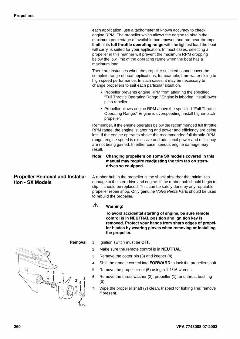
Propellers
each application, use a tachometer of known accuracy to check engine RPM. The propeller which allows the engine to obtain the maximum percentage of available horsepower, and run near the top limit of its full throttle operating range with the lightest load the boat will carry, is suited for your application. In most cases, selecting a propeller in this manner will prevent the maximum RPM dropping below the low limit of the operating range when the boat has a maximum load.
There are instances when the propeller selected cannot cover the complete range of boat applications, for example, from water skiing to high speed performance. In such cases, it may be necessary to change propellers to suit each particular situation.
• Propeller prevents engine RPM from attaining the specified “Full Throttle Operating Range.” Engine is laboring, install lower pitch ropeller.
• Propeller allows engine RPM above the specified “Full Throttle Operating Range.” Engine is overspeeding, install higher pitch propeller.
Remember, if the engine operates below the recommended full throttle RPM range, the engine is laboring and power and efficiency are being lost. If the engine operates above the recommended full throttle RPM range, engine speed is excessive and additional power and efficiency are not being gained. In either case, serious engine damage may result.
Note! Changing propellers on some SX models covered in this manual may require readjusting the trim tab on stern-drives so equipped.
Propeller Removal and Installa-tion - SX Models
A rubber hub in the propeller is the shock absorber that minimizes damage to the sterndrive and engine. If the rubber hub should begin to slip, it should be replaced. This can be safely done by any reputable propeller repair shop. Only genuine Volvo Penta Parts should be used to rebuild the propeller.
Warning!
To avoid accidental starting of engine, be sure remote control is in NEUTRAL position and ignition key is removed. Protect your hands from sharp edges of propel-ler blades by wearing gloves when removing or installing the propeller.
Removal 1. Ignition switch must be OFF.
2. Make sure the remote control is in NEUTRAL.
3. Remove the cotter pin (3) and keeper (4).
4. Shift the remote control into FORWARD to lock the propeller shaft.
5. Remove the propeller nut (5) using a 1-1/16 wrench.
6. Remove the thrust washer (2), propeller (1), and thrust bushing (6).
7. Wipe the propeller shaft (7) clean. Inspect for fishing line; remove if present.
1
23
4
5
67
22864
260 VPA 7743008 07-2003
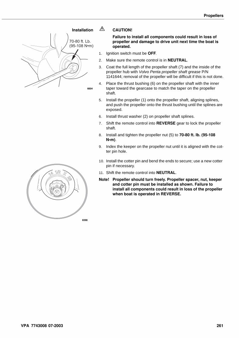
Propellers
Installation CAUTION!
Failure to install all components could result in loss of propeller and damage to drive unit next time the boat is operated.
1. Ignition switch must be OFF.
2. Make sure the remote control is in NEUTRAL.
3. Coat the full length of the propeller shaft (7) and the inside of the propeller hub with Volvo Penta propeller shaft grease P/N 1141644; removal of the propeller will be difficult if this is not done.
4. Place the thrust bushing (6) on the propeller shaft with the inner taper toward the gearcase to match the taper on the propeller shaft.
5. Install the propeller (1) onto the propeller shaft, aligning splines, and push the propeller onto the thrust bushing until the splines are exposed.
6. Install thrust washer (2) on propeller shaft splines.
7. Shift the remote control into REVERSE gear to lock the propeller shaft.
8. Install and tighten the propeller nut (5) to 70-80 ft. lb. (95-108 N•m).
9. Index the keeper on the propeller nut until it is aligned with the cot-ter pin hole.
10. Install the cotter pin and bend the ends to secure; use a new cotter pin if necessary.
11. Shift the remote control into NEUTRAL.
Note! Propeller should turn freely. Propeller spacer, nut, keeper and cotter pin must be installed as shown. Failure to install all components could result in loss of the propeller when boat is operated in REVERSE.
70-80 ft. Lb.(95-108 N•m)
6604
6598
VPA 7743008 07-2003 261
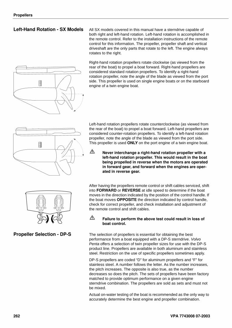
Propellers
Left-Hand Rotation - SX Models All SX models covered in this manual have a sterndrive capable of both right and left-hand rotation. Left-hand rotation is accomplished in the remote control. Refer to the installation instructions of the remote control for this information. The propeller, propeller shaft and vertical driveshaft are the only parts that rotate to the left. The engine always rotates to the right.
Right-hand rotation propellers rotate clockwise (as viewed from the rear of the boat) to propel a boat forward. Right-hand propellers are considered standard rotation propellers. To identify a right-hand rotation propeller, note the angle of the blade as viewed from the port side. This propeller is used on single engine boats or on the starboard engine of a twin engine boat.
Left-hand rotation propellers rotate counterclockwise (as viewed from the rear of the boat) to propel a boat forward. Left-hand propellers are considered counter-rotation propellers. To identify a left-hand rotation propeller, note the angle of the blade as viewed from the port side. This propeller is used ONLY on the port engine of a twin engine boat.
Never interchange a right-hand rotation propeller with a left-hand rotation propeller. This would result in the boat being propelled in reverse when the motors are operated in forward gear, and forward when the engines are oper-ated in reverse gear.
After having the propellers remote control or shift cables serviced, shift into FORWARD or REVERSE at idle speed to determine if the boat moves in the direction indicated by the position of the control handle. If the boat moves OPPOSITE the direction indicated by control handle, check for correct propeller, and check installation and adjustment of the remote control and shift cables.
Failure to perform the above test could result in loss of boat control.
Propeller Selection - DP-S The selection of propellers is essential for obtaining the best performance from a boat equipped with a DP-S sterndrive. Volvo Penta offers a selection of twin propeller sizes for use with the DP-S product line. Propellers are available in both aluminum and stainless steel. Restriction on the use of specific propellers sometimes apply.
DP-S propellers are coded “D” for aluminum propellers and “F” for stainless steel. A number follows the letter. As the number increases, the pitch increases. The opposite is also true, as the number decreases so does the pitch. The sets of propellers have been factory matched to provide optimum performance on a given engine sterndrive combination. The propellers are sold as sets and must not be mixed.
Actual on-water testing of the boat is recommended as the only way to accurately determine the best engine and propeller combination.
262 VPA 7743008 07-2003
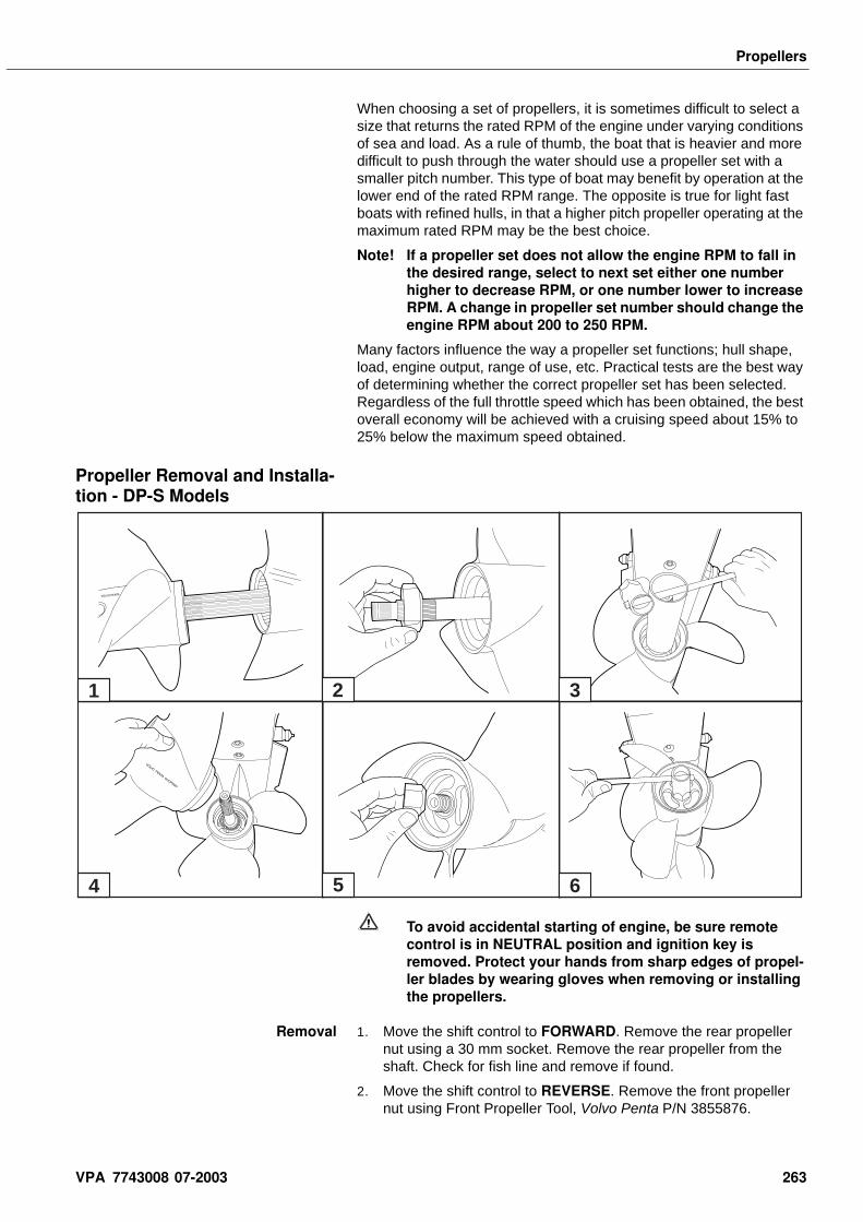
Propellers
When choosing a set of propellers, it is sometimes difficult to select a size that returns the rated RPM of the engine under varying conditions of sea and load. As a rule of thumb, the boat that is heavier and more difficult to push through the water should use a propeller set with a smaller pitch number. This type of boat may benefit by operation at the lower end of the rated RPM range. The opposite is true for light fast boats with refined hulls, in that a higher pitch propeller operating at the maximum rated RPM may be the best choice.
Note! If a propeller set does not allow the engine RPM to fall in the desired range, select to next set either one number higher to decrease RPM, or one number lower to increase RPM. A change in propeller set number should change the engine RPM about 200 to 250 RPM.
Many factors influence the way a propeller set functions; hull shape, load, engine output, range of use, etc. Practical tests are the best way of determining whether the correct propeller set has been selected. Regardless of the full throttle speed which has been obtained, the best overall economy will be achieved with a cruising speed about 15% to 25% below the maximum speed obtained.
Propeller Removal and Installa-tion - DP-S Models
To avoid accidental starting of engine, be sure remote control is in NEUTRAL position and ignition key is removed. Protect your hands from sharp edges of propel-ler blades by wearing gloves when removing or installing the propellers.
Removal 1. Move the shift control to FORWARD. Remove the rear propeller nut using a 30 mm socket. Remove the rear propeller from the shaft. Check for fish line and remove if found.
2. Move the shift control to REVERSE. Remove the front propeller nut using Front Propeller Tool, Volvo Penta P/N 3855876.
1 2 3
4 5 6
VPA 7743008 07-2003 263
Propellers
Remove the front propeller from the shaft. Check for fish line and remove if found.
3. Wipe both propeller shafts clean and check for damage. Repair any damage.
Installation 1. Coat the full length of both propeller shafts with Volvo Penta Pro-peller Shaft Grease P/N 1141644.
2. Place the remote control in the FORWARD gear position to lock the propeller shafts.
3. Install the front propeller. Install the front propeller nut and tighten to 45 ft. lb. (60 N•m) using Front Propeller Tool, Volvo Penta P/N 3855876.
4. Place the remote control in the REVERSE gear position to lock the propeller shafts.
5. Install the rear propeller. Install the rear propeller nut and tighten to 50 ft. lb. (70 N•m).
Note! Failure to install the propellers as indicated could result in the loss of the rear propeller and damage to the drive unit when the boat is operated.
Condition of Boat Bottom The condition of the boat bottom affects the boat’s performance considerably. Marine growth (slime, barnacles, or other foreign matter), which will accumulate in fresh or salt water, will cut down on performance and speed. The boat bottom should be cleaned periodically in accordance with manufacturer’s recommendations.
Bottom Painting If your boat is in water where marine growth is a problem, the use of an anti-fouling paint will reduce the growth rate. See your dealer for an anti-fouling paint that is suitable for your area.
• Tin base anti-fouling paint (TBTA or TBTF*) is recommended where its use is permitted.
• Copper base anti-fouling paint may be used, but will require more frequent inspection and replacement of sacrificial anodes. DO NOT PAINT any part of the vertical drive with copper base anti-fouling paint.
* Tributyl Tin Adipate or Tributyl Tin Fluoride
Note! Painting the sterndrive with copper base paint will accel-erate galvanic corrosion.
• Vinyl-butyl base anti-fouling paint is a recommended alternative.
• DO NOT USE any graphite base anti-fouling paint.
Note! Never paint anti-corrosion anodes, or their effectiveness will be lost.
See the Volvo Penta Parts Catalog for anode kits that provide further corrosion protection for the sterndrive assembly.
Boat Trailers It is extremely important that the trailer fits the boat properly. Loss of boat performance and speed may be due to improper trailer support and excessive tie-down pressure which has caused the boat bottom to hook. The boat should rest firmly on the trailer with maximum tie-down pressure applied at the bow and transom only.
264 VPA 7743008 07-2003
Propellers
Boat Trim - SX and DP-S The power trim/tilt system allows for trimming the sterndrive in or out to compensate for a major change in boat loading and weight distribution.
DP-S sterndrives should limit trim to ± 5°. Serious propeller and vertical drive damage can occur if the sterndrive is operated at trim angle that is too high or low.
Propeller Hub Replacement A rubber hub in the propeller is the shock absorber which minimizes the chance of damaging the propeller, lower gearcase, or drive train components during shifting or striking an underwater object. If the hub should become damaged and slip, it can be replaced by an authorized service dealer or propeller station.
High Altitude Operation A performance loss at altitudes above 3500 ft. can be expected. If you are boating above 3500 ft. elevation for a short term, a lower pitch propeller will restore some of the lost performance. Long term use above altitudes of 3500 ft. may require a change in gear ratio. Contact your dealer regarding installation of a high altitude gear set.
To avoid permanent engine damage, be sure that a boat modified for high altitude operation is properly identified. Return it to its original gear ratio if operated for prolonged periods at or near sea level.
VPA 7743008 07-2003 265

Notes . . . . . . . . . . . . . . . . . . . . . . . . . . . . . . . . . . . . . . . . . . . . . . . . . . . . . . . . . . . . . . . . . . . . . . . . . . .
. . . . . . . . . . . . . . . . . . . . . . . . . . . . . . . . . . . . . . . . . . . . . . . . . . . . . . . . . . . . . . . . . . . . . . . . . . .
. . . . . . . . . . . . . . . . . . . . . . . . . . . . . . . . . . . . . . . . . . . . . . . . . . . . . . . . . . . . . . . . . . . . . . . . . . .
. . . . . . . . . . . . . . . . . . . . . . . . . . . . . . . . . . . . . . . . . . . . . . . . . . . . . . . . . . . . . . . . . . . . . . . . . . .
. . . . . . . . . . . . . . . . . . . . . . . . . . . . . . . . . . . . . . . . . . . . . . . . . . . . . . . . . . . . . . . . . . . . . . . . . . .
. . . . . . . . . . . . . . . . . . . . . . . . . . . . . . . . . . . . . . . . . . . . . . . . . . . . . . . . . . . . . . . . . . . . . . . . . . .
. . . . . . . . . . . . . . . . . . . . . . . . . . . . . . . . . . . . . . . . . . . . . . . . . . . . . . . . . . . . . . . . . . . . . . . . . . .
. . . . . . . . . . . . . . . . . . . . . . . . . . . . . . . . . . . . . . . . . . . . . . . . . . . . . . . . . . . . . . . . . . . . . . . . . . .
. . . . . . . . . . . . . . . . . . . . . . . . . . . . . . . . . . . . . . . . . . . . . . . . . . . . . . . . . . . . . . . . . . . . . . . . . . .
. . . . . . . . . . . . . . . . . . . . . . . . . . . . . . . . . . . . . . . . . . . . . . . . . . . . . . . . . . . . . . . . . . . . . . . . . . .
. . . . . . . . . . . . . . . . . . . . . . . . . . . . . . . . . . . . . . . . . . . . . . . . . . . . . . . . . . . . . . . . . . . . . . . . . . .
. . . . . . . . . . . . . . . . . . . . . . . . . . . . . . . . . . . . . . . . . . . . . . . . . . . . . . . . . . . . . . . . . . . . . . . . . . .
. . . . . . . . . . . . . . . . . . . . . . . . . . . . . . . . . . . . . . . . . . . . . . . . . . . . . . . . . . . . . . . . . . . . . . . . . . .
. . . . . . . . . . . . . . . . . . . . . . . . . . . . . . . . . . . . . . . . . . . . . . . . . . . . . . . . . . . . . . . . . . . . . . . . . . .
. . . . . . . . . . . . . . . . . . . . . . . . . . . . . . . . . . . . . . . . . . . . . . . . . . . . . . . . . . . . . . . . . . . . . . . . . . .
. . . . . . . . . . . . . . . . . . . . . . . . . . . . . . . . . . . . . . . . . . . . . . . . . . . . . . . . . . . . . . . . . . . . . . . . . . .
. . . . . . . . . . . . . . . . . . . . . . . . . . . . . . . . . . . . . . . . . . . . . . . . . . . . . . . . . . . . . . . . . . . . . . . . . . .
. . . . . . . . . . . . . . . . . . . . . . . . . . . . . . . . . . . . . . . . . . . . . . . . . . . . . . . . . . . . . . . . . . . . . . . . . . .
. . . . . . . . . . . . . . . . . . . . . . . . . . . . . . . . . . . . . . . . . . . . . . . . . . . . . . . . . . . . . . . . . . . . . . . . . . .
. . . . . . . . . . . . . . . . . . . . . . . . . . . . . . . . . . . . . . . . . . . . . . . . . . . . . . . . . . . . . . . . . . . . . . . . . . .
. . . . . . . . . . . . . . . . . . . . . . . . . . . . . . . . . . . . . . . . . . . . . . . . . . . . . . . . . . . . . . . . . . . . . . . . . . .
. . . . . . . . . . . . . . . . . . . . . . . . . . . . . . . . . . . . . . . . . . . . . . . . . . . . . . . . . . . . . . . . . . . . . . . . . . .
. . . . . . . . . . . . . . . . . . . . . . . . . . . . . . . . . . . . . . . . . . . . . . . . . . . . . . . . . . . . . . . . . . . . . . . . . . .
. . . . . . . . . . . . . . . . . . . . . . . . . . . . . . . . . . . . . . . . . . . . . . . . . . . . . . . . . . . . . . . . . . . . . . . . . . .
. . . . . . . . . . . . . . . . . . . . . . . . . . . . . . . . . . . . . . . . . . . . . . . . . . . . . . . . . . . . . . . . . . . . . . . . . . .
. . . . . . . . . . . . . . . . . . . . . . . . . . . . . . . . . . . . . . . . . . . . . . . . . . . . . . . . . . . . . . . . . . . . . . . . . . .
. . . . . . . . . . . . . . . . . . . . . . . . . . . . . . . . . . . . . . . . . . . . . . . . . . . . . . . . . . . . . . . . . . . . . . . . . . .
. . . . . . . . . . . . . . . . . . . . . . . . . . . . . . . . . . . . . . . . . . . . . . . . . . . . . . . . . . . . . . . . . . . . . . . . . . .
. . . . . . . . . . . . . . . . . . . . . . . . . . . . . . . . . . . . . . . . . . . . . . . . . . . . . . . . . . . . . . . . . . . . . . . . . . .
. . . . . . . . . . . . . . . . . . . . . . . . . . . . . . . . . . . . . . . . . . . . . . . . . . . . . . . . . . . . . . . . . . . . . . . . . . .
. . . . . . . . . . . . . . . . . . . . . . . . . . . . . . . . . . . . . . . . . . . . . . . . . . . . . . . . . . . . . . . . . . . . . . . . . . .
. . . . . . . . . . . . . . . . . . . . . . . . . . . . . . . . . . . . . . . . . . . . . . . . . . . . . . . . . . . . . . . . . . . . . . . . . . .
. . . . . . . . . . . . . . . . . . . . . . . . . . . . . . . . . . . . . . . . . . . . . . . . . . . . . . . . . . . . . . . . . . . . . . . . . . .
265 VPA 7743008 07-2003


�������
���
��
�� ����
���������������� ������������������������� �����
��� � ���������� ������������
�