Embed Size (px)
Citation preview
Switch Gear, Symmetrical Fault on Three Phase Systems 16.1 Switchgear The apparatus used for switching, controlling and protecting the electrical circuits and equipment is known as switchgear. The switchgear equipment is essentially concerned with switching and interrupting currents either under normal or abnormal operating conditions. The highball glass switch with ordinary fuse is the simplest form of switchgear and is used to control and protect lights and other equipment in homes, offices etc. For circuits of higher rating, a high-rupturing capacity (H.R.C.) fuse in combination with a switch may serve the purpose of controlling and protecting the circuit. However, such a switchgear cannot be used successfully on high voltage system (3·3 kV) for two reasons. • Firstly, when a fuse blows, it takes sometime to replace it and consequently there is
interruption of service to the customers.
• Secondly, the fuse cannot successfully interrupt large fault currents that result from the faults on high voltage system.
11/28/2016 Power System/ Dr. Ramzi A. Abdul-Halem 1
16.3 Switchgear Equipment Switchgear covers a wide range of equipment concerned with switching and interrupting currents under both normal and abnormal conditions.
It includes switches, fuses, circuit breakers, relays and other equipment.
A brief account of these devices is given below.
1. Switches. A switch is a device which is used to open or close an electrical circuit in a convenient way.
The switches may be classified into
• (i) air switches
• (ii) oil switches.
(i) Air-break switch. It is an air switch and is designed to open a circuit under load.
(ii) Oil switches. As the name implies, the contacts of such switches are opened under oil, usually transformer oil.
11/28/2016 Power System/ Dr. Ramzi A. Abdul-Halem 2
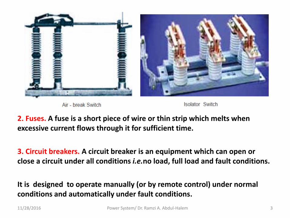
2. Fuses. A fuse is a short piece of wire or thin strip which melts when excessive current flows through it for sufficient time.
3. Circuit breakers. A circuit breaker is an equipment which can open or close a circuit under all conditions i.e.no load, full load and fault conditions.
It is designed to operate manually (or by remote control) under normal conditions and automatically under fault conditions.
11/28/2016 Power System/ Dr. Ramzi A. Abdul-Halem 3
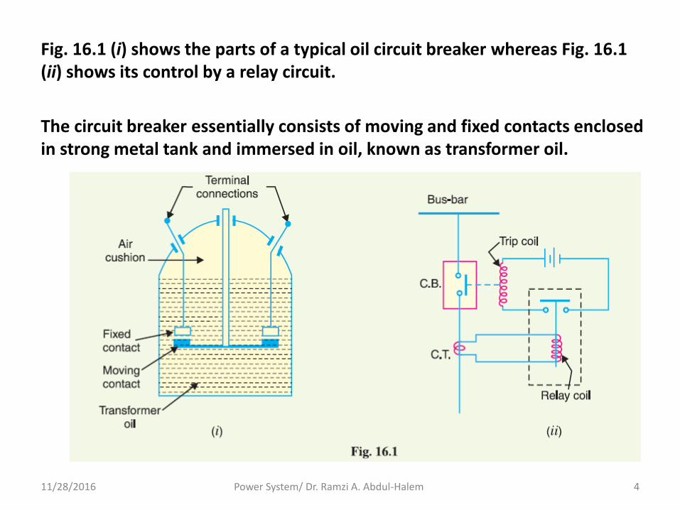
Fig. 16.1 (i) shows the parts of a typical oil circuit breaker whereas Fig. 16.1 (ii) shows its control by a relay circuit.
The circuit breaker essentially consists of moving and fixed contacts enclosed in strong metal tank and immersed in oil, known as transformer oil.
11/28/2016 Power System/ Dr. Ramzi A. Abdul-Halem 4
4. Relays. A relay is a device which detects the fault and supplies information to the breaker for circuit interruption.
Fig. 16.1 (ii) shows a typical relay circuit. It can be divided into three parts i.e.
• (i) The primary winding of a current transformer (C.T.) which is connected in series with the circuit to be protected. The primary winding often consists of the main conductor itself.
• (ii) The second circuit is the secondary winding of C.T. connected to the relay operating coil.
• (iii) The third circuit is the tripping circuit which consists of a source of supply, trip coil of circuit breaker and the relay stationary contacts.
Under normal load conditions, the e.m.f. of the secondary winding of C.T. is small and the current flowing in the relay operating coil is insufficient to close the relay contacts.
This keeps the trip coil of the circuit breaker unenergized. Consequently, the contacts of the circuit breaker remain closed and it carries the normal load current.
11/28/2016 Power System/ Dr. Ramzi A. Abdul-Halem 5
When a fault occurs, a large current flows through the primary of C.T.
This increases the secondary e.m.f. and hence the current through the relay operating coil.
The relay contacts are closed and the trip coil of the circuit breaker is energized to open the contacts of the circuit breaker.
16.4 Bus-Bar Arrangements
When a number of generators or feeders operating at the same voltage have to be directly connected electrically, bus-bars are used as the common electrical component.
Bus-bars are copper rods or thin walled tubes and operate at constant voltage.
11/28/2016 Power System/ Dr. Ramzi A. Abdul-Halem 6
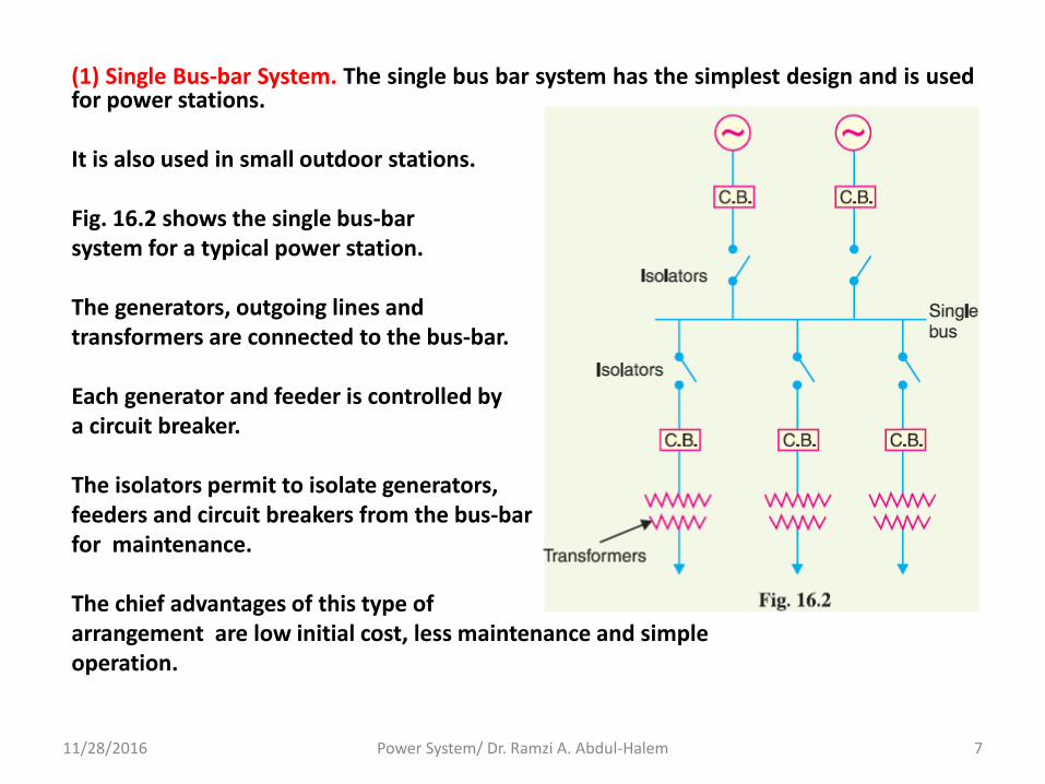
(1) Single Bus-bar System. The single bus bar system has the simplest design and is used for power stations. It is also used in small outdoor stations. Fig. 16.2 shows the single bus-bar system for a typical power station. The generators, outgoing lines and transformers are connected to the bus-bar. Each generator and feeder is controlled by a circuit breaker. The isolators permit to isolate generators, feeders and circuit breakers from the bus-bar for maintenance. The chief advantages of this type of arrangement are low initial cost, less maintenance and simple operation.
11/28/2016 Power System/ Dr. Ramzi A. Abdul-Halem 7
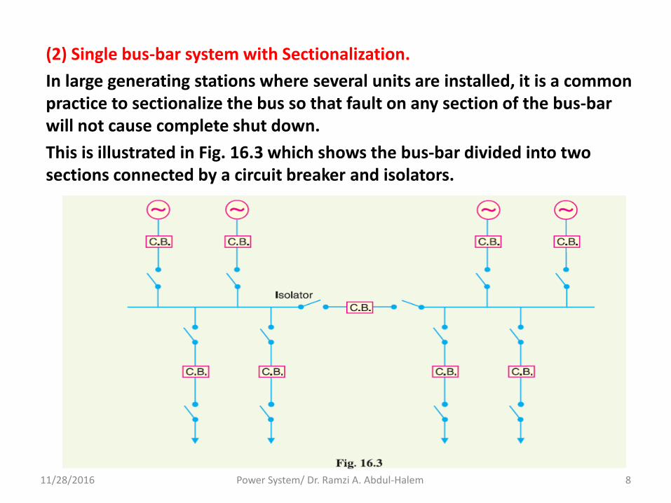
(2) Single bus-bar system with Sectionalization.
In large generating stations where several units are installed, it is a common practice to sectionalize the bus so that fault on any section of the bus-bar will not cause complete shut down.
This is illustrated in Fig. 16.3 which shows the bus-bar divided into two sections connected by a circuit breaker and isolators.
11/28/2016 Power System/ Dr. Ramzi A. Abdul-Halem 8
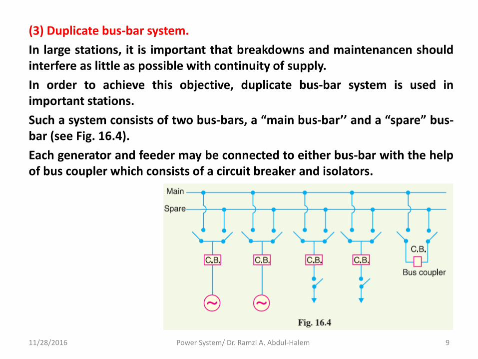
(3) Duplicate bus-bar system.
In large stations, it is important that breakdowns and maintenancen should interfere as little as possible with continuity of supply.
In order to achieve this objective, duplicate bus-bar system is used in important stations.
Such a system consists of two bus-bars, a “main bus-bar’’ and a “spare” bus-bar (see Fig. 16.4).
Each generator and feeder may be connected to either bus-bar with the help of bus coupler which consists of a circuit breaker and isolators.
11/28/2016 Power System/ Dr. Ramzi A. Abdul-Halem 9
16.5 Switchgear Accommodation
The main components of a switchgear are circuit breakers, switches, bus-bars, instruments and instrument transformers.
It is necessary to house the switchgear in power stations and sub-stations in such a way so as to protection personnel during operation and maintenance and to ensure that the effects of fault on any section of the gear are narrow to a limited region.
Depending upon the voltage to be handled, switchgear may be broadly classified into
• (i) outdoor type
• (ii) indoor type.
11/28/2016 Power System/ Dr. Ramzi A. Abdul-Halem 10
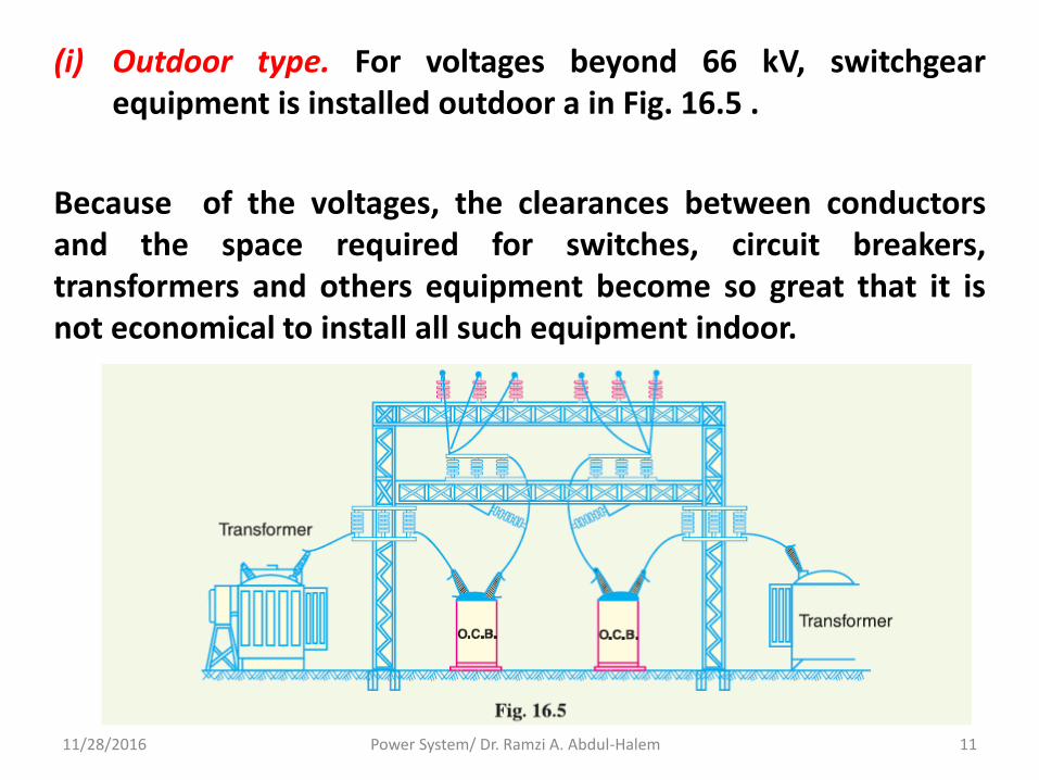
(i) Outdoor type. For voltages beyond 66 kV, switchgear equipment is installed outdoor a in Fig. 16.5 .
Because of the voltages, the clearances between conductors and the space required for switches, circuit breakers, transformers and others equipment become so great that it is not economical to install all such equipment indoor.
11/28/2016 Power System/ Dr. Ramzi A. Abdul-Halem 11

(ii) Indoor type. For voltages below 66 kV, switchgear is generally installed indoor because of economic considerations.
16.6 Short-Circuit
Whenever a fault occurs on a network such that a large current flows in one or more phases, a short circuit is said to have occurred.
When a short circuit occurs, a heavy current called short circuit current flows through the circuit.
This can be illustrated by referring to Fig. 16.6
where a single phase generator of voltage V and
internal impedance Zi is supplying to a load Z.
Under normal conditions, the current in the
circuit is limited by load impedance Z.
However, if the load terminals get shorted due to any reason, the circuit impedance is reduced to a very low value ; being Zi in this case.
As Zi is very small, therefore, a large current flows through the circuit.
This is called short-circuit current.
11/28/2016 Power System/ Dr. Ramzi A. Abdul-Halem 12
16.7 Short-Circuit Currents
Most of the failures on the power system lead to short-circuit fault and cause heavy current to flow in the system.
The calculations of these short-circuit currents are important for the
following reasons :
• (i) It is necessary, to know the maximum possible values of short-circuit current so that switchgear of suitable rating may be installed to interrupt them.
• (ii) Determines the setting and sometimes the types and location of protective system.
• (iii) Determines the size of the protective reactors which must be inserted in the system so that the circuit breaker is able to withstand the fault current.
• (iv) Enables us to make proper selection of the associated apparatus (e.g. bus-bars, current transformers etc.) so that they can withstand the forces that arise due to the occurrence of short circuits.
11/28/2016 Power System/ Dr. Ramzi A. Abdul-Halem 13
16.8 Faults in a Power System A fault occurs when two or more conductors that normally operate with a potential difference come in contact with each other. These faults may be caused by sudden failure of a piece of equipment, accidental damage or short-circuit to overhead lines or by insulation failure resulting from lightning surges. Regardless of the causes, the faults in a 3-phase system can be classified into two main categories : • (i) Symmetrical faults • (ii) Unsymmetrical faults
(i) Symmetrical faults. That fault which gives rise to symmetrical fault currents (i.e. equal faults currents with 120o displacement) is called a symmetrical fault. The most common example of symmetrical fault is when all the three conductors of a 3-phase line are brought together simultaneously into a short-circuit condition. This is fully discussed in chapter 17.
11/28/2016 Power System/ Dr. Ramzi A. Abdul-Halem 14
(ii) Unsymmetrical faults. Those faults which give rise to unsymmetrical currents (i.e. unequal line currents with unequal displacement) are called unsymmetrical faults.
The unsymmetrical faults may take one of the following forms :
(a) Single line-to-ground fault
(b) Line-to-line fault
(c) Double line-to-ground fault
The great majority of faults on the power system are of unsymmetrical nature; the most common type being a short-circuit from one line to ground.
The calculations of such fault currents are made by “symmetrical components” method. This is fully discussed in chapter 18.
11/28/2016 Power System/ Dr. Ramzi A. Abdul-Halem 15