Embed Size (px)
Citation preview


Swiss Manufacturing Plant
Since more than 40 years E-tec has been active in the electronics interconnection field (IC Sockets, PCB interconnect products, D-Sub’s, Switches, RF Connectors, etc.) and 20 years experience in Test Socket and adaptors on a world-wide basis. E-tec offers a very comprehensive range of industry standard products as well as many customized products which can be found in a variety of application fields, such as aeronautics, military, medical, communications, automotive, multi-media and many others. We offer very short delivery times from prototype small volume to large volume production series. Thanks to our own production facility we aim to offer a solution to all your problems.
Quality assurance is an essential part of our production process, since our main objective is to offer products which correspond to the highest quality standards.
For any further details please contact E-tec or your closest sales office.
INDEX Part-Number Type Page About E-tec Test Sockets & Adapters A Available Retention Frames B Adapter & Converter Solutions C Socket & Retention System Selector Guides D General Product Information E ABG xxx-Exxx-xx X 55 xx BGA Solder Adapter 14 BPC xxxx-xx xx-xx XX xx BGA Socket ClamShell “Professional” & “Injection Molded” 7 & 11 BPE xxxx-xx xx-xx XX xx BGA Socket ClamShell “Economy” 6 & 11 BPF xxxx-xx xx-xx XX xx BGA Socket FastLock 1 & 11 BPH xxxx-xx xx-xx XX xx BGA Socket ClamShell “Aluminium open” 9 BPM xxxx-xx xx-xx XX xx BGA Socket ClamShell “Injection Molded” 8 BPQ xxxx-xx xx-xx XX xx BGA Socket QuickLock 4 & 11 BPW xxxx-xx xx-xx XX xx BGA Socket TwistLock 2 & 11 BPZ xxxx-xx xx-xx XX xx BGA Socket LeverLock 5 & 11 BUC xxxx-xx xx-xx XX xx BGA Socket ClamShell “Professional” 7 & 11 BUE xxxx-xx xx-xx XX xx BGA Socket ClamShell “Economy” 6 & 11 BUF xxxx-xx xx-xx XX xx BGA Socket FastLock 1 & 11 BUQ xxxx-xx xx-xx XX xx BGA Socket QuickLock 4 & 11 BUW xxxx-xx xx-xx XX xx BGA Socket TwistLock 2 & 11 BUZ xxxx-xx xx-xx XX xx BGA Socket LeverLock 5 & 11 CPC xxxx-xx xx-xx XX xx Column Grid Socket ClamShell “Professional” 7 & 11 CPE xxxx-xx xx-xx XX xx Column Grid Socket ClamShell “Economy” 6 & 11 CPF xxxx-xx xx-xx XX xx Column Grid Socket FastLock 1 & 11 CPH xxxx-xx xx-xx XX xx Column Grid Socket ClamShell “Aluminium open” 9 & 10 CPM xxxx-xx xx-xx XX xx Column Grid Socket ClamShell “Injection Molded” 8 CPQ xxxx-xx xx-xx XX xx Column Grid Socket QuickLock 4 & 11 CPW xxxx-xx xx-xx XX xx Column Grid Socket TwistLock 2 & 11 CPZ xxxx-xx xx-xx XX xx Column Grid Socket LeverLock 5 & 11 EBE xxxx-xx xx-xx XX xx BGA Socket Elastomer Interposer Type ClamShell “Economy” 12 EBF xxxx-xx xx-xx XX xx BGA Socket Elastomer Interposer Type FastLock 12 EBQ xxxx-xx xx-xx XX xx BGA Socket Elastomer Interposer Type QuickLock 12 EBW xxxx-xx xx-xx XX xx BGA Socket Elastomer Interposer Type TwistLock 12 EGF xxxx-xx xx-xx XX xx GullWing Chip Socket Elastomer Interposer Type FastLock 12 EGQ xxxx-xx xx-xx XX xx GullWing Chip Socket Elastomer Interposer Type QuickLock 12 EGW xxxx-xx xx-xx XX xx GullWing Chip Socket Elastomer Interposer TwistLock 12 ELE xxxx-xx xx-xx XX xx LGA/QFN Socket Elastomer Interposer Type ClamShell “Economy” 12 ELF xxxx-xx xx-xx XX xx LGA/QFN Socket Elastomer Interposer Type FastLock 12 ELQ xxxx-xx xx-xx XX xx LGA/QFN Socket Elastomer Interposer Type QuickLock 12 ELW xxxx-xx xx-xx XX xx LGA/QFN Socket Elastomer Interposer Type TwistLock 12 FCT xxx-Xxxx-xx ZIF Test sockets for Flex Cables 19 LPC xxxx-xx xx-xx XX xx Land Grid Socket ClamShell “Professional” 7 & 11 LPE xxxx-xx xx-xx XX xx Land Grid Socket ClamShell “Economy” 6 & 11 LPF xxxx-xx xx-xx XX xx Land Grid Socket FastLock 1 & 11 LPH xxxx-xx xx-xx XX xx Land Grid Socket ClamShell “Aluminium open” 18 LPM xxxx-xx xx-xx XX xx Land Grid Socket ClamShell “Injection Molded” 8 LPQ xxxx-xx xx-xx XX xx Land Grid Socket QuickLock 4 & 11 LPW xxxx-xx xx-xx XX xx Land Grid Socket TwistLock 2 & 11 LPZ xxxx-xx xx-xx XX xx Land Grid Socket LeverLock 5 & 8 LQE xxxx-xx xx-xx XX xx QFN/MLF/MLP Socket ClamShell “Economy” 16 LQF xxxx-xx xx-xx XX xx QFN/MLF/MLP Socket FastLock 16 LQQ xxxx-xx xx-xx XX xx QFN/MLF/MLP Socket QuickLock 16 LQW xxxx-xx xx-xx XX xx QFN/MLF/MLP Socket TwistLock 16 MGS xxxx-Exxx-xx X 95 xx MiniGrid Socket 15 MGS xxxx-SB01-xx X 95 xx MiniGrid SMT Solder Ball Adapter 13 QFC xxxx-xx xx-xx XX xx GullWing Chip Socket ClamShell 17 QFF xxxx-xx xx-xx XX xx GullWing Chip Socket FastLock 17 QFQ xxxx-xx xx-xx XX xx GullWing Chip Socket QuickLock 17 QFW xxxx-xx xx-xx XX xx GullWing Chip Socket ScrewLock 17 TOL-7CN-TORQUE Torque Limiting Screwdriver Kit 18
Test Sockets & Adapter
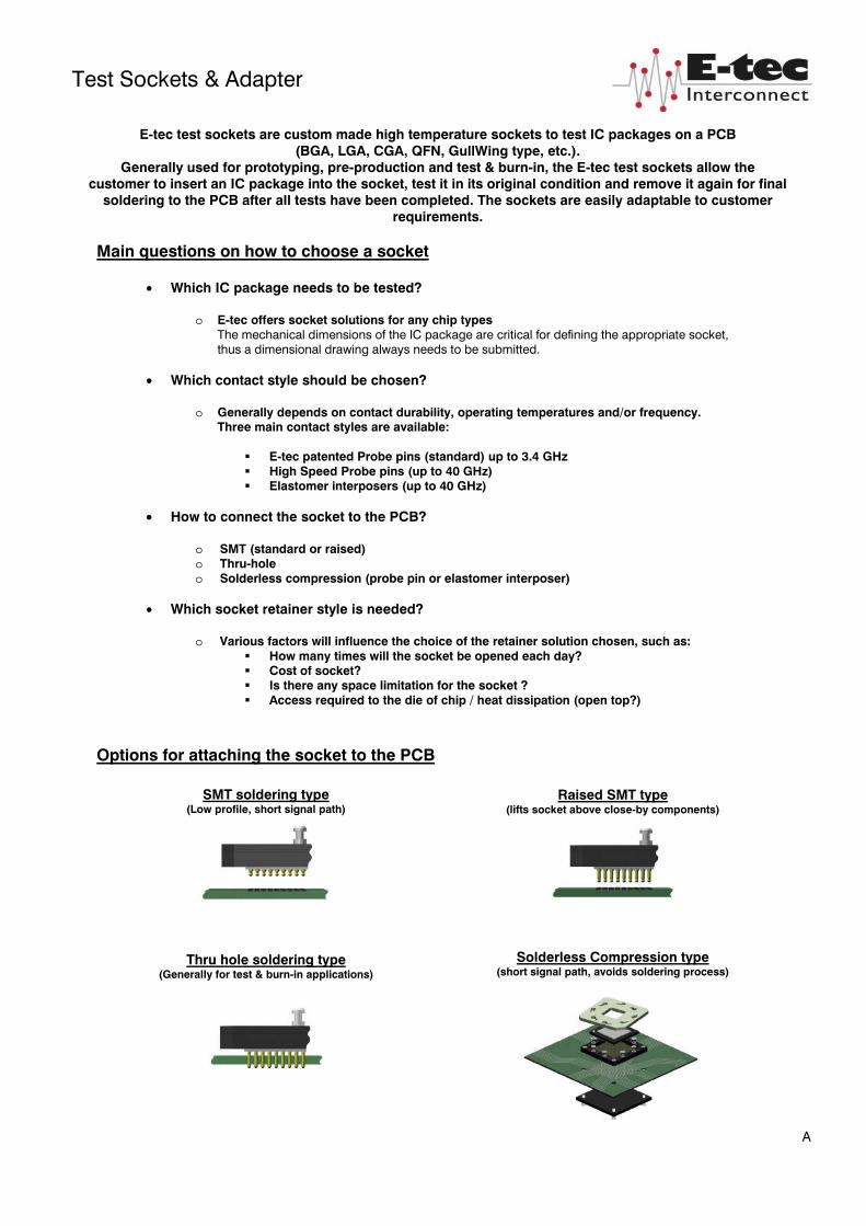
E-tec test sockets are custom made high temperature sockets to test IC packages on a PCB (BGA, LGA, CGA, QFN, GullWing type, etc.).
Generally used for prototyping, pre-production and test & burn-in, the E-tec test sockets allow the customer to insert an IC package into the socket, test it in its original condition and remove it again for final
soldering to the PCB after all tests have been completed. The sockets are easily adaptable to customer requirements.
Main questions on how to choose a socket
• Which IC package needs to be tested?
o E-tec offers socket solutions for any chip types The mechanical dimensions of the IC package are critical for defining the appropriate socket, thus a dimensional drawing always needs to be submitted.
• Which contact style should be chosen?
o Generally depends on contact durability, operating temperatures and/or frequency. Three main contact styles are available:
E-tec patented Probe pins (standard) up to 3.4 GHz High Speed Probe pins (up to 40 GHz) Elastomer interposers (up to 40 GHz)
• How to connect the socket to the PCB?
o SMT (standard or raised) o Thru-hole o Solderless compression (probe pin or elastomer interposer)
• Which socket retainer style is needed?
o Various factors will influence the choice of the retainer solution chosen, such as: How many times will the socket be opened each day? Cost of socket? Is there any space limitation for the socket ? Access required to the die of chip / heat dissipation (open top?)
Options for attaching the socket to the PCB
A
SMT soldering type
(Low profile, short signal path)
Thru hole soldering type (Generally for test & burn-in applications)
Raised SMT type (lifts socket above close-by components)
Solderless Compression type (short signal path, avoids soldering process)
Swiss Manufacturing Plant
Since more than 40 years E-tec has been active in the electronics interconnection field (IC Sockets, PCB interconnect products, D-Sub’s, Switches, RF Connectors, etc.) and 20 years experience in Test Socket and adaptors on a world-wide basis. E-tec offers a very comprehensive range of industry standard products as well as many customized products which can be found in a variety of application fields, such as aeronautics, military, medical, communications, automotive, multi-media and many others. We offer very short delivery times from prototype small volume to large volume production series. Thanks to our own production facility we aim to offer a solution to all your problems.
Quality assurance is an essential part of our production process, since our main objective is to offer products which correspond to the highest quality standards.
For any further details please contact E-tec or your closest sales office.
INDEX Part-Number Type Page About E-tec Test Sockets & Adapters A Available Retention Frames B Adapter & Converter Solutions C Socket & Retention System Selector Guides D General Product Information E ABG xxx-Exxx-xx X 55 xx BGA Solder Adapter 14 BPC xxxx-xx xx-xx XX xx BGA Socket ClamShell “Professional” & “Injection Molded” 7 & 11 BPE xxxx-xx xx-xx XX xx BGA Socket ClamShell “Economy” 6 & 11 BPF xxxx-xx xx-xx XX xx BGA Socket FastLock 1 & 11 BPH xxxx-xx xx-xx XX xx BGA Socket ClamShell “Aluminium open” 9 BPM xxxx-xx xx-xx XX xx BGA Socket ClamShell “Injection Molded” 8 BPQ xxxx-xx xx-xx XX xx BGA Socket QuickLock 4 & 11 BPW xxxx-xx xx-xx XX xx BGA Socket TwistLock 2 & 11 BPZ xxxx-xx xx-xx XX xx BGA Socket LeverLock 5 & 11 BUC xxxx-xx xx-xx XX xx BGA Socket ClamShell “Professional” 7 & 11 BUE xxxx-xx xx-xx XX xx BGA Socket ClamShell “Economy” 6 & 11 BUF xxxx-xx xx-xx XX xx BGA Socket FastLock 1 & 11 BUQ xxxx-xx xx-xx XX xx BGA Socket QuickLock 4 & 11 BUW xxxx-xx xx-xx XX xx BGA Socket TwistLock 2 & 11 BUZ xxxx-xx xx-xx XX xx BGA Socket LeverLock 5 & 11 CPC xxxx-xx xx-xx XX xx Column Grid Socket ClamShell “Professional” 7 & 11 CPE xxxx-xx xx-xx XX xx Column Grid Socket ClamShell “Economy” 6 & 11 CPF xxxx-xx xx-xx XX xx Column Grid Socket FastLock 1 & 11 CPH xxxx-xx xx-xx XX xx Column Grid Socket ClamShell “Aluminium open” 9 & 10 CPM xxxx-xx xx-xx XX xx Column Grid Socket ClamShell “Injection Molded” 8 CPQ xxxx-xx xx-xx XX xx Column Grid Socket QuickLock 4 & 11 CPW xxxx-xx xx-xx XX xx Column Grid Socket TwistLock 2 & 11 CPZ xxxx-xx xx-xx XX xx Column Grid Socket LeverLock 5 & 11 EBE xxxx-xx xx-xx XX xx BGA Socket Elastomer Interposer Type ClamShell “Economy” 12 EBF xxxx-xx xx-xx XX xx BGA Socket Elastomer Interposer Type FastLock 12 EBQ xxxx-xx xx-xx XX xx BGA Socket Elastomer Interposer Type QuickLock 12 EBW xxxx-xx xx-xx XX xx BGA Socket Elastomer Interposer Type TwistLock 12 EGF xxxx-xx xx-xx XX xx GullWing Chip Socket Elastomer Interposer Type FastLock 12 EGQ xxxx-xx xx-xx XX xx GullWing Chip Socket Elastomer Interposer Type QuickLock 12 EGW xxxx-xx xx-xx XX xx GullWing Chip Socket Elastomer Interposer TwistLock 12 ELE xxxx-xx xx-xx XX xx LGA/QFN Socket Elastomer Interposer Type ClamShell “Economy” 12 ELF xxxx-xx xx-xx XX xx LGA/QFN Socket Elastomer Interposer Type FastLock 12 ELQ xxxx-xx xx-xx XX xx LGA/QFN Socket Elastomer Interposer Type QuickLock 12 ELW xxxx-xx xx-xx XX xx LGA/QFN Socket Elastomer Interposer Type TwistLock 12 FCT xxx-Xxxx-xx ZIF Test sockets for Flex Cables 19 LPC xxxx-xx xx-xx XX xx Land Grid Socket ClamShell “Professional” 7 & 11 LPE xxxx-xx xx-xx XX xx Land Grid Socket ClamShell “Economy” 6 & 11 LPF xxxx-xx xx-xx XX xx Land Grid Socket FastLock 1 & 11 LPH xxxx-xx xx-xx XX xx Land Grid Socket ClamShell “Aluminium open” 18 LPM xxxx-xx xx-xx XX xx Land Grid Socket ClamShell “Injection Molded” 8 LPQ xxxx-xx xx-xx XX xx Land Grid Socket QuickLock 4 & 11 LPW xxxx-xx xx-xx XX xx Land Grid Socket TwistLock 2 & 11 LPZ xxxx-xx xx-xx XX xx Land Grid Socket LeverLock 5 & 8 LQE xxxx-xx xx-xx XX xx QFN/MLF/MLP Socket ClamShell “Economy” 16 LQF xxxx-xx xx-xx XX xx QFN/MLF/MLP Socket FastLock 16 LQQ xxxx-xx xx-xx XX xx QFN/MLF/MLP Socket QuickLock 16 LQW xxxx-xx xx-xx XX xx QFN/MLF/MLP Socket TwistLock 16 MGS xxxx-Exxx-xx X 95 xx MiniGrid Socket 15 MGS xxxx-SB01-xx X 95 xx MiniGrid SMT Solder Ball Adapter 13 QFC xxxx-xx xx-xx XX xx GullWing Chip Socket ClamShell 17 QFF xxxx-xx xx-xx XX xx GullWing Chip Socket FastLock 17 QFQ xxxx-xx xx-xx XX xx GullWing Chip Socket QuickLock 17 QFW xxxx-xx xx-xx XX xx GullWing Chip Socket ScrewLock 17 TOL-7CN-TORQUE Torque Limiting Screwdriver Kit 18
Test Sockets & Adapter
E-tec test sockets are custom made high temperature sockets to test IC packages on a PCB (BGA, LGA, CGA, QFN, GullWing type, etc.).
Generally used for prototyping, pre-production and test & burn-in, the E-tec test sockets allow the customer to insert an IC package into the socket, test it in its original condition and remove it again for final
soldering to the PCB after all tests have been completed. The sockets are easily adaptable to customer requirements.
Main questions on how to choose a socket
• Which IC package needs to be tested?
o E-tec offers socket solutions for any chip types The mechanical dimensions of the IC package are critical for defining the appropriate socket, thus a dimensional drawing always needs to be submitted.
• Which contact style should be chosen?
o Generally depends on contact durability, operating temperatures and/or frequency. Three main contact styles are available:
E-tec patented Probe pins (standard) up to 3.4 GHz High Speed Probe pins (up to 40 GHz) Elastomer interposers (up to 40 GHz)
• How to connect the socket to the PCB?
o SMT (standard or raised) o Thru-hole o Solderless compression (probe pin or elastomer interposer)
• Which socket retainer style is needed?
o Various factors will influence the choice of the retainer solution chosen, such as: How many times will the socket be opened each day? Cost of socket? Is there any space limitation for the socket ? Access required to the die of chip / heat dissipation (open top?)
Options for attaching the socket to the PCB
A
SMT soldering type
(Low profile, short signal path)
Thru hole soldering type (Generally for test & burn-in applications)
Raised SMT type (lifts socket above close-by components)
Solderless Compression type (short signal path, avoids soldering process)

Test Sockets & Adapter
Available Retention frames
B
TwistLock
LeverLock
FastLock
ClamShell
Professional closed top
QuickLock without lever
for low pincount
with lever for high pincount
open top (on request)
Economy open top
Aluminum open top
Injection Molded Type M1 for Chips up to 17 x 17mm
Aluminum open top with button
Injection Molded Type M1 for Chips up to 17 x 17mm
SMT Adapter solution for plugging a Test Socket
SMT Adapter solution for plugging a test socket
Solderball or solid pin surface mount sockets. Easy to solder (especially high pincount), and easy plugging a Test Socket after soldering.
Step 1: solder MiniGrid Socket (MGS) to PCB Step 2: plug Test Socket into MiniGrid Socket (MGS)
Test Socket with alignment plate and Gold plated contacts
Thru hole MGS Series SMT pin hole MGS Series Ball MGS Series
Converter Adapter solution
Generally for high volume requirements . MiniGrid sockets available with solder balls or regular solid pins. Step 1: MiniGrid Socket (MGS) soldered to PCB Step 2: chip soldered to adapter board (converting BGA to PGA) Step 3: Plug adapter board into MiniGrid Socket(MGS)
Chip
Solder Adapter
Thru hole MGS Series SMT pin hole MGS Series Ball MGS Series
C

Test Sockets & Adapter
Socket & Retention System Selector Guides
The below Socket & Retention System Selector Guides will help you to make the right choice.
The options indicated refer to standard options. If you should not find what you need or if your specs should vary from the below chart, please contact your closest E-tec office, since we will most likely be able to offer a customized solution also.
Socket Selector Guide
Socket style
Low
est P
itch
Contact interface
Avai
labl
e Te
mpe
ratu
re ra
nge Chip types
Reg
ular
Pro
be
pin
(up
to 3
.4
GH
z)
Hig
h sp
eed
(up
to 4
0 G
Hz)
Rep
lace
able
co
ntac
ts
BGA/
CSP
CG
A
LGA
QFN
LCC
Gul
lwin
g (Q
FP,
TSO
P, S
SOP
, et
c)
Oth
ers
Surface Mount 0.50mm Yes No No -60°C to +150°C Yes Yes Yes Yes Yes Yes on request
Raised Surface Mount 0.50mm Yes No No -60°C to +150°C Yes Yes Yes Yes Yes Yes on
request
Thru-hole 0.50mm Yes No No -60°C to +150°C Yes Yes Yes Yes Yes Yes on request
Solderless Probe pin 0.40mm Yes Yes
only high
speed probes
-60°C to +150°C up to +450°C
on request Yes Yes Yes Yes Yes Yes on
request
Solderless Elastomer 0.30mm n/a Yes Yes -35°C to +125°C Yes No Yes Yes No Yes on request
Retention System Selector Guide
Retention frame style
Soc
ket C
ost
Ope
n to
p
Ope
n/cl
ose
cycl
es
Soc
ket s
ize
Sock
et h
eigh
t abo
ve
boar
d
Tool
s re
quire
d to
ope
n/cl
ose
Torq
ue to
ol o
ptio
n
avai
labl
e w
ith
inte
grat
ed h
eats
ink
Rec
omm
ende
d fo
r S
MT
sock
ets
Acc
epte
d ch
ip
heig
hts
Acce
pted
max
. chi
p he
ight
var
iatio
ns
from
min
to m
ax
Acc
epte
d m
in/m
ax
chip
siz
e
Avai
labl
e fo
r el
asto
mer
soc
kets
Avai
labl
e fo
r "g
ullw
ing
chip
" so
cket
s Av
aila
ble
for g
ullin
g ch
ips
with
"tie
bar
" at
tach
ed to
legs
TwistLock / ScrewLock Low Yes 1K smallest lowest Yes Yes Yes Yes no limit no limit min 1.5x1.5mm
max no limit Yes Yes Yes
FastLock Low Yes 10K small medium No Yes Yes Yes, with locating
pegs no limit 2.5mm min 1.5x1.5mm
max no limit Yes Yes Yes
Economy ClamShell Low Yes 10K small medium No Yes Yes
Yes, with locating
pegs no limit 2.5mm min 7x7mm
max no limit Yes No No
LeverLock Medium Yes 1K small low No No No Yes, with locating
pegs no limit 0.40mm min 15x15mm
max 40x40mm Yes No No
QuickLock Medium to High on request 25K medium high No No No Yes min 0.5mm
max 3.5mm 3.0mm min 1.5x1.5mm max no limit Yes Yes Yes
Aluminum Professional ClamShell
High on request 25K largest high No No No Yes, with locating
pegs
min 0.5mm max 4.0mm 3.5mm min 4x4mm
max no limit Yes Yes Yes
Injecztion Molded ClamShell
Low Yes M2 and M3 10K medium medium No No No
Yes, with locating
pegs
min 0.5mm max 4.0mm 3.5mm min 4x4mm
max 35x35mm Yes Yes No
Adapter solution (mini-grid socket & pluggable Test socket)
Depends on
retention system
Depends on
retention system
Depends on
retention system
small adapter
base high
Depends on
retention system
Depends on
retention system
Depends on
retention system
Yes with small size
locking systems
Depends on retention system
Depends on
retention system
Depends on retention system Yes Yes Yes
D
General Product Information
General Socket Recommendations TwistLock Test Socket
1. Use the E-tec torque tool TOL-7CN-TORQUE with appropriate torque setting for TwistLock sockets. Generally 7cNm up to 800 pins and 7cNm to 10cNm for higher pin counts.
2. Close the screws of the retainer with light tightening first and then fully tighten the screws one after each other. For sockets with 4 or 8 screws tighten the screws “cross wise” to apply equal forces.
SMT Test Socket 1. Use solder paste without silver or less than 0.5% silver content. 2. Solder profile & socket mounting recommendations are available for download from our homepage www.e-tec.com 3. Whenever possible use locating pegs which are tin plated for soldering to the PCB. This avoids the solder
joints from being stressed during handling of the socket. Socket life cycle can be heavily reduced if used without locating pegs.
4. For high pin count sockets, it’s preferable to solder a light weight mini-grid adapter to the PCB first and then plug the test socket into that adapter.
5. Choose the raised SMT socket for lifting the socket above close-by components. Special clearances in the socket body can also be offered on request.
Solderless Test Socket 1. Use gold plated PCB pads (hard gold if possible). 2. PCB pads must be flush or higher than the solder mask for reliable interconnection with the socket. 3. Clearance for close-by components or components underneath the PCB can be offered on request.
Test Socket with Mini-Grid SMT Adapter When inserting the test socket into the mini-grid adapter, make sure that the pin alignment plate has been positioned at the tip of the test socket pins. During insertion, this plate will then be pressed backwards and remain seated in-between the socket and the mini-grid adapter. This pin alignment board ensures correct alignment of the test socket pins onto the pins of the mini-grid adapter and thus reduces the risk of damaging the test socket pins during insertion. If the adapter socket has been removed from the mini-grid socket, then this pin alignment board needs to be pushed back to the tip of the test socket pins prior to reinserting the test socket into the mini-grid adapter.
E-tec Patented Probe Pin Designs
BGA ball grid array contact design
(patented) standard size solderballs
BGA ball grid array contact design
(patented) small size solderballs
LGA land grid array contact design
(patented)
CGA Column grid contact design
(patented)
E

Ball / Land Grid Array Sockets FastLock Type
E-tec is now the leading BGA socket manufacturer. EP patents 0829188, 0897655 US patents 6190181, 6249440 Patented in other countries.
FastLock sockets are available for any chip size and grid pattern. The SMT socket is simply placed and reflowed onto the PCB in the same way as the chip and occupies only a small amount of additional board space. The solderless sockets are mounted with 2 or 4 mounting pegs to the PCB depending on the chip size. The FastLock retainer uses a thumbscrew which does not require any tools for opening/closing of the socket. Torque tools or adjustment of pressdown force are available with this locking system also.
We aim to solve your requirements – your custom sets our standards!
Please note, we will always request the chip data to ensure we offer a compatible socket.
FastLock Type
SMT style
Ø 0,60mm/.024“ if pitch 1,27mm Ø 0,50mm/.020“ if pitch 1,00mm Ø 0,40mm/.016“ if pitch 0,80mm Ø 0,35mm/.014“ if pitch 0,75mm Ø 0,35mm/.014“ if pitch 0,65mm Ø 0,30mm/.012“ if pitch 0,50mm
Soldertail style Solderless Compression style (FastLock Type as example shown)
Soldertail dimension:
Ø 0,42mm/.016” if pitch 1,27mm Ø 0,29mm/.011” if pitch 1,00mm Ø 0,29mm/.011” if pitch 0,80mm Ø 0,27mm/.010” if pitch 0,75mm Ø 0,27mm/.010” if pitch 0,65mm Ø 0,27mm/.010” if pitch 0,50mm Ø 0,17mm/.007” if pitch 0,40mm
PCB solder hole:
Ø 0,60mm/.024” if pitch 1,27mm Ø 0,50mm/.020” if pitch 1,00mm Ø 0,40mm/.016” if pitch 0,80mm Ø 0,35mm/.014” if pitch 0,75mm Ø 0,35mm/.014” if pitch 0,65mm Ø 0,35mm/.014” if pitch 0,50mm Ø 0,25mm/.010” if pitch 0,40mm
PCB Pad Layout
You may request any specific socket dimension from [email protected] gold plated pads Ø 0,70mm/.027“ if pitch 1,27mm gold plated pads Ø 0,60mm/.024“ if pitch 1,00mm gold plated pads Ø 0,50mm/.020“ if pitch 0,80mm gold plated pads Ø 0,45mm/.018“ if pitch 0,75mm gold plated pads Ø 0,40mm/.016“ if pitch 0,65mm gold plated pads Ø 0,35mm/.012“ if pitch 0,50mm gold plated pads Ø 0,25mm/.010“ if pitch 0,40mm
Solderless Compression Type and other locking systems (on
request)
Important Note: Please check the ball diameters & heights of your chip prior to ordering the standard E-tec BGA (BPC) sockets. Any deviation has to be communicated to E-tec in order to check compatibility with the standard socket design and if necessary to obtain a special order code adapted to your chip dimensions. The standard solderball diameters & heights are the following:
Pitch ball diameters ball height min min 0.50mm 0.25mm 0.20mm 0.65mm 0.25mm 0.20mm 0.75mm 0.25mm 0.20mm 0.80mm 0.40mm 0.25mm 1.00mm 0.55mm 0.30mm 1.27mm & higher 0.65mm 0.50mm
If the minimum ball diameter of a given chip falls below the above indications, then a BUF
socket will generally be proposed.
Specifications Mechanical data
Contact life Retention system life Solderability Individual contact force Material Insulator (RoHS compliant) Terminal (RoHS compliant) Contact (RoHS compliant) Electrical data Contact resistance Current rating Insulation resistance at 500V DC Breakdown voltage at 60 Hz Capacitance Inductance
Operating temperature
100K cycles min. 10K cycles min. as per IEC 60068-2-58 40 grams max. High temp plastic or Polyepoxy Brass BeCu < 100 mΩ 1A - 2A depend on pitch 100 MΩ if 0.50 to 0.80mm pitch 500 MΩ 1.00mm pitch upwards 500V min. < 1 pF < 2 nH
−60°C to +150°C ; 260°C for 60 sec.
Recommendations: Solder paste – Please use a solder paste w/o any silver! Solder profile – Please refer to our website www.e-tec.com
E-tec solderless sockets are adapted to a standard PCB thickness of 1.60mm. For a different PCB thickness, please inform E-tec first! SMT FastLock sockets are recommended to be ordered with locating pegs for soldering to the PCB, to avoid the solderjoints from being stressed due to the torque forces
applied with this locking system. If used without locating pegs, the life cycle of the socket may be heavily reduced. For high pincount SMT sockets, E-tec recommends the use of a pluggable thru-hole socket mounted into a MiniGrid Adapter (see also pages 10, 11 & 12 for more details).
How to order
X X F x x x x - x x x x - x x X X x x L optional for locating pegs
Device Type Socket Type Pitch Grid Code Config Code Plating B = Ball Grid
L = Land Grid
C = Column Grid
P = socket for LGA, CGA and BGA chips with standard diameter solderballs (see dimensions in table above)
U = socket for small diameter solderballs
04 = 0,40mm 05 = 0,50mm 06 = 0,65mm 07 = 0,75mm 08 = 0,80mm
10 = 1,00mm 12 = 1,27mm 15 = 1,50mm
others on request
will be given by the factory after receipt of the chip datasheet
95 = tin/gold (tin leadfree)
55 = gold only for
Compression Type
Nbr of contacts Contact Type
depends on ballcount of chip
30 = standard SMT...(„A“ = 1,20mm if 1,27mm pitch; 0,80mm if 1,00mm pitch, 0.60 if 0,80mm pitch; 0,40mm if <0.80mm pitch)
29 = raised SMT..(„A“ = 5,00mm if 1,27mm pitch; 3,20mm if 1,00mm pitch; 2,80mm if 0,80mm pitch, 2.30mm if <0.80mm pitch)
28 = special raised SMT - only for 1.00 & 0.80mm pitch….....(„A“ = 4,50mm)
70 = standard solder tail…………..….(„A“ = 3.30 if 1.27mm pitch, 2.80 if 1.00mm or 0.80mm pitch, 2,30mm if <0.80mm pitch)
90 & 91 = compression type (see page 8 for more details)
1
FastLock Type
Ball / Land Grid Array Sockets TwistLock Type
E-tec is now the leading BGA socket manufacturer. EP patents 0829188, 0897655 US patents 6190181, 6249440 Patented in other countries.
TwistLock sockets are generally chosen when relatively low insertion / extraction cycles are required and when the cost of the socket is a predominant factor. The TwistLock socket extends by around 6.00mm beyond the outer ball row and special clearances can be offered on request.
We aim to solve your requirements - many different terminals and configurations are available. Your custom sets our standards!
Please note, we will always request the chip data to ensure we offer a compatible socket. SMT Style
PCB Pad Layout
Ø 0,60mm/.024“ if pitch 1,27mm Ø 0,50mm/.020“ if pitch 1,00mm Ø 0,40mm/.016“ if pitch 0,80mm Ø 0,35mm/.014“ if pitch 0,75mm Ø 0,35mm/.014“ if pitch 0,65mm Ø 0,30mm/.012“ if pitch 0,50mm
You may request any specific socket dimension from
For top view socket dimension pls. ref. to separate catalog page
Important Note: Please check the ball diameters & heights of your chip prior to ordering the standard E-tec BGA (BPW) sockets. Any deviation has to be communicated to E-tec in order to check compatibility with the standard socket design and if necessary to obtain a special order code adapted to your chip dimensions. The standard solderball diameters & heights are the following: Pitch ball diameters ball height min min 0.50mm 0.25mm 0.20mm 0.65mm 0.25mm 0.20mm 0.75mm 0.25mm 0.20mm 0.80mm 0.40mm 0.25mm 1.00mm 0.55mm 0.30mm 1.27mm & higher 0.65mm 0.50mm
If the minimum ball diameter of a given chip falls below the above indications, then a BUW socket will generally be proposed.
Soldertail Style Specifications
Soldertail: Ø 0,42mm/.016” if pitch 1,27mm Ø 0,29mm/.011” if pitch 1,00mm Ø 0,29mm/.011” if pitch 0,80mm Ø 0,27mm/.010” if pitch 0,75mm Ø 0,27mm/.010” if pitch 0,65mm Ø 0,27mm/.010” if pitch 0,50mm Ø 0,17mm/.007” if pitch 0,40mm
Mechanical data Contact life Retention System life Solderability Individual contact force Max. torque for retention screws Material Insulator (RoHS compliant) Terminal (RoHS compliant) Contact (RoHS compliant) Electrical data Contact resistance Current rating Insulation resistance at 500V DC Breakdown voltage at 60 Hz Capacitance Inductance Operating temperature
100K cycles min. 1K cycles min. as per IEC 60068-2-58 40 grams max. up to 800 pins = 7cNm or 10 oz-inch as of 800 pins = 7cNm to 10cNm or 10 oz-inch to 14 oz-inch High temp plastic or Polyepoxy Brass BeCu < 100 mΩ 1A - 2A depend on pitch 100 MΩ if 0.50mm to 0.80mm pitch 500 MΩ 1.00mm pitch upwards 500V min. < 1 pF < 2 nH −60°C to +150°C ; 260°C for 60 sec.
PCB Hole Layout
PCB solder hole: Ø 0,60mm/.024” if pitch 1,27mm Ø 0,50mm/.020” if pitch 1,00mm Ø 0,40mm/.016” if pitch 0,80mm Ø 0,35mm/.014” if pitch 0,75mm Ø 0,35mm/.014” if pitch 0,65mm Ø 0,35mm/.014” if pitch 0,50mm Ø 0,25mm/.010” if pitch 0,40mm
Recommendations: Solder paste – Please use a solder paste w/o any silver! Solder profile – Please refer to our website www.e-tec.com
E-tec solderless sockets are adapted to a standard PCB thickness of 1.60mm. For a different PCB thickness, please inform E-tec first! For high pincount SMT sockets, E-tec recommends the use of a pluggable thru-hole socket mounted into a MiniGrid Adapter (see also page 10, 11 & 12 for more details)
For SMT sockets in general, E-tec recommends the use of locating pegs which can be soldered to the PCB for added mechanical strength.
How to order
X X W x x x x - x x x x - x x X X 95 L optional for locating pegs
Device Type Socket Type Pitch Grid Code Config Code Plating B = Ball Grid
L = Land Grid
C = Column Grid
P = socket for LGA, CGA and BGA chips with standard diameter solderballs (see dimensions in table above)
U = socket for small diameter solderballs
04 = 0,40mm 05 = 0,50mm 06 = 0,65mm 07 = 0,75mm 08 = 0,80mm
10 = 1,00mm 12 = 1,27mm 15 = 1,50mm
others on request
will be given by the factory after receipt of the chip datasheet
95 = tin/gold (tin leadfree)
Nbr of contacts Contact Type
depends on ballcount of chip
30 = standard SMT...( „A“ = 1,20mm if 1,27mm pitch; 0,80mm if 1,00mm pitch, 0.60 if 0,80mm pitch; 0,40mm if <0.80mm pitch )
29 = raised SMT..( „A“ = 5,00mm if 1,27mm pitch; 3,20mm if 1,00mm pitch; 2,80mm if 0,80mm pitch, 2.30mm if <0.80mm pitch )
28 = special raised SMT - only for 1.00 & 0.80mm pitch…..... ( „A“ = 4,50mm )
70 = standard solder tail……..…...….( „A“ = 3.30 if 1.27mm pitch, 2.80 if 1.00mm or 0.80mm pitch, 2,30mm if <0.80mm pitch )
90 & 91 = compression type (see page 8 for more details)
2
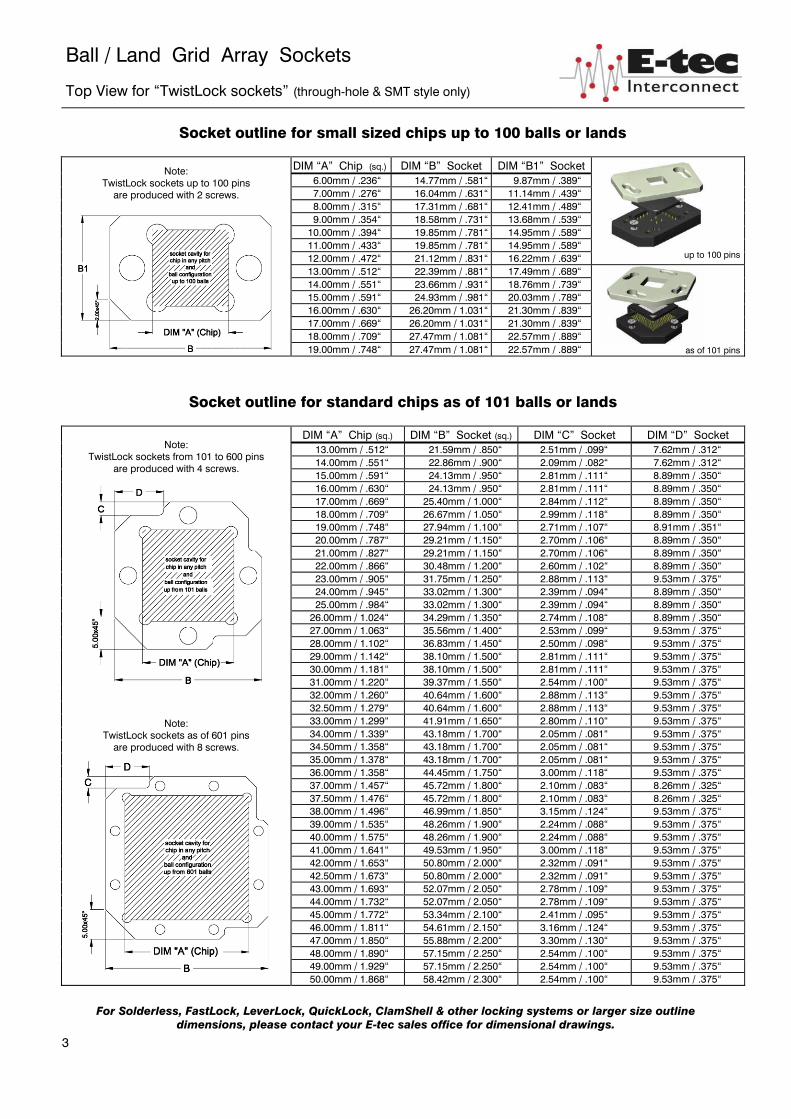
Ball / Land Grid Array Sockets
Top View for “TwistLock sockets” (through-hole & SMT style only)
Socket outline for small sized chips up to 100 balls or lands
Note: TwistLock sockets up to 100 pins
are produced with 2 screws.
DIM “A” Chip (sq.) DIM “B” Socket DIM “B1” Socket
up to 100 pins
6.00mm / .236“ 14.77mm / .581“ 9.87mm / .389“ 7.00mm / .276“ 16.04mm / .631“ 11.14mm / .439“ 8.00mm / .315“ 17.31mm / .681“ 12.41mm / .489“ 9.00mm / .354“ 18.58mm / .731“ 13.68mm / .539“ 10.00mm / .394“ 19.85mm / .781“ 14.95mm / .589“ 11.00mm / .433“ 19.85mm / .781“ 14.95mm / .589“ 12.00mm / .472“ 21.12mm / .831“ 16.22mm / .639“ 13.00mm / .512“ 22.39mm / .881“ 17.49mm / .689“
as of 101 pins
14.00mm / .551“ 23.66mm / .931“ 18.76mm / .739“ 15.00mm / .591“ 24.93mm / .981“ 20.03mm / .789“ 16.00mm / .630“ 26.20mm / 1.031“ 21.30mm / .839“ 17.00mm / .669“ 26.20mm / 1.031“ 21.30mm / .839“ 18.00mm / .709“ 27.47mm / 1.081“ 22.57mm / .889“ 19.00mm / .748“ 27.47mm / 1.081“ 22.57mm / .889“
Socket outline for standard chips as of 101 balls or lands
Note:
TwistLock sockets from 101 to 600 pins are produced with 4 screws.
Note: TwistLock sockets as of 601 pins
are produced with 8 screws.
DIM “A” Chip (sq.) DIM “B” Socket (sq.) DIM “C” Socket DIM “D” Socket 13.00mm / .512“ 21.59mm / .850“ 2.51mm / .099“ 7.62mm / .312“ 14.00mm / .551“ 22.86mm / .900“ 2.09mm / .082“ 7.62mm / .312“ 15.00mm / .591“ 24.13mm / .950“ 2.81mm / .111“ 8.89mm / .350“ 16.00mm / .630“ 24.13mm / .950“ 2.81mm / .111“ 8.89mm / .350“ 17.00mm / .669“ 25.40mm / 1.000“ 2.84mm / .112“ 8.89mm / .350“ 18.00mm / .709“ 26.67mm / 1.050“ 2.99mm / .118“ 8.89mm / .350“ 19.00mm / .748“ 27.94mm / 1.100“ 2.71mm / .107“ 8.91mm / .351“ 20.00mm / .787“ 29.21mm / 1.150“ 2.70mm / .106“ 8.89mm / .350“ 21.00mm / .827“ 29.21mm / 1.150“ 2.70mm / .106“ 8.89mm / .350“ 22.00mm / .866“ 30.48mm / 1.200“ 2.60mm / .102“ 8.89mm / .350“ 23.00mm / .905“ 31.75mm / 1.250“ 2.88mm / .113“ 9.53mm / .375“ 24.00mm / .945“ 33.02mm / 1.300“ 2.39mm / .094“ 8.89mm / .350“ 25.00mm / .984“ 33.02mm / 1.300“ 2.39mm / .094“ 8.89mm / .350“ 26.00mm / 1.024“ 34.29mm / 1.350“ 2.74mm / .108“ 8.89mm / .350“ 27.00mm / 1.063“ 35.56mm / 1.400“ 2.53mm / .099“ 9.53mm / .375“ 28.00mm / 1.102“ 36.83mm / 1.450“ 2.50mm / .098“ 9.53mm / .375“ 29.00mm / 1.142“ 38.10mm / 1.500“ 2.81mm / .111“ 9.53mm / .375“ 30.00mm / 1.181“ 38.10mm / 1.500“ 2.81mm / .111“ 9.53mm / .375“ 31.00mm / 1.220“ 39.37mm / 1.550“ 2.54mm / .100“ 9.53mm / .375“ 32.00mm / 1.260“ 40.64mm / 1.600“ 2.88mm / .113“ 9.53mm / .375“ 32.50mm / 1.279“ 40.64mm / 1.600“ 2.88mm / .113“ 9.53mm / .375“ 33.00mm / 1.299“ 41.91mm / 1.650“ 2.80mm / .110“ 9.53mm / .375“ 34.00mm / 1.339“ 43.18mm / 1.700“ 2.05mm / .081“ 9.53mm / .375“ 34.50mm / 1.358“ 43.18mm / 1.700“ 2.05mm / .081“ 9.53mm / .375“ 35.00mm / 1.378“ 43.18mm / 1.700“ 2.05mm / .081“ 9.53mm / .375“ 36.00mm / 1.358“ 44.45mm / 1.750“ 3.00mm / .118“ 9.53mm / .375“ 37.00mm / 1.457“ 45.72mm / 1.800“ 2.10mm / .083“ 8.26mm / .325“ 37.50mm / 1.476“ 45.72mm / 1.800“ 2.10mm / .083“ 8.26mm / .325“ 38.00mm / 1.496“ 46.99mm / 1.850“ 3.15mm / .124“ 9.53mm / .375“ 39.00mm / 1.535“ 48.26mm / 1.900“ 2.24mm / .088“ 9.53mm / .375“ 40.00mm / 1.575“ 48.26mm / 1.900“ 2.24mm / .088“ 9.53mm / .375“ 41.00mm / 1.641“ 49.53mm / 1.950“ 3.00mm / .118“ 9.53mm / .375“ 42.00mm / 1.653“ 50.80mm / 2.000“ 2.32mm / .091“ 9.53mm / .375“ 42.50mm / 1.673“ 50.80mm / 2.000“ 2.32mm / .091“ 9.53mm / .375“ 43.00mm / 1.693“ 52.07mm / 2.050“ 2.78mm / .109“ 9.53mm / .375“ 44.00mm / 1.732“ 52.07mm / 2.050“ 2.78mm / .109“ 9.53mm / .375“ 45.00mm / 1.772“ 53.34mm / 2.100“ 2.41mm / .095“ 9.53mm / .375“ 46.00mm / 1.811“ 54.61mm / 2.150“ 3.16mm / .124“ 9.53mm / .375“ 47.00mm / 1.850“ 55.88mm / 2.200“ 3.30mm / .130“ 9.53mm / .375“ 48.00mm / 1.890“ 57.15mm / 2.250“ 2.54mm / .100“ 9.53mm / .375“ 49.00mm / 1.929“ 57.15mm / 2.250“ 2.54mm / .100“ 9.53mm / .375“ 50.00mm / 1.868“ 58.42mm / 2.300“ 2.54mm / .100“ 9.53mm / .375“
For Solderless, FastLock, LeverLock, QuickLock, ClamShell & other locking systems or larger size outline dimensions, please contact your E-tec sales office for dimensional drawings.
3
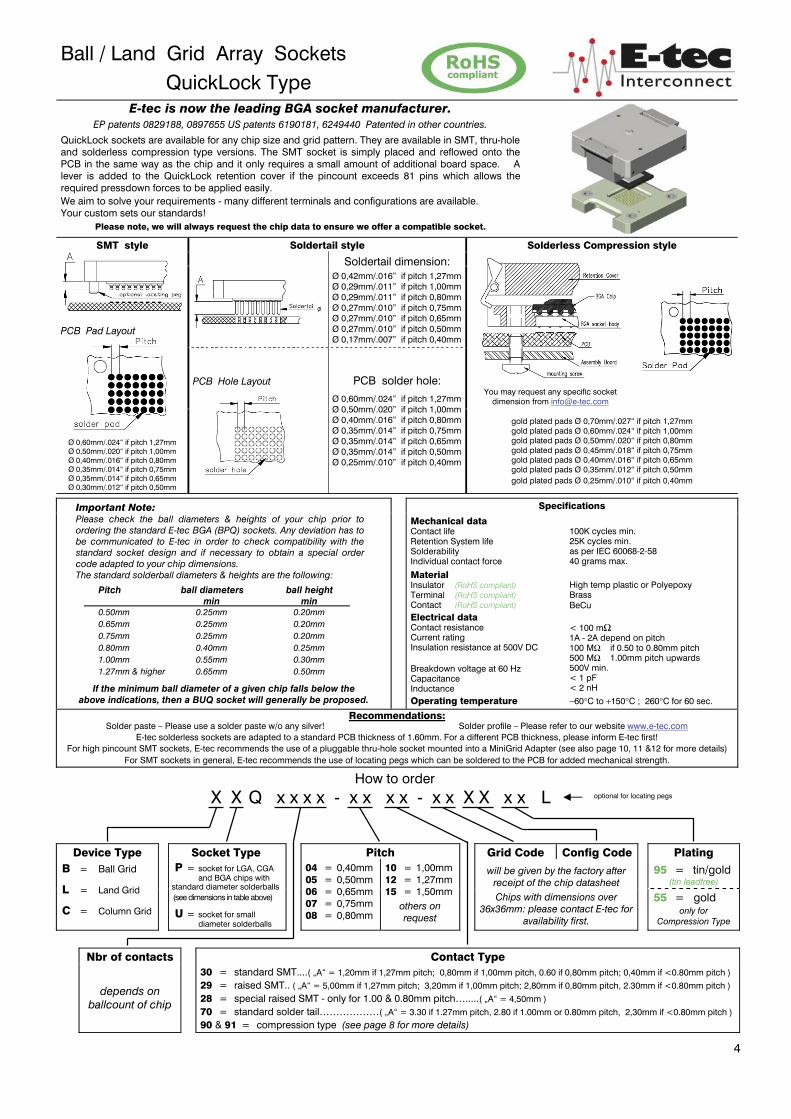
Ball / Land Grid Array Sockets QuickLock Type
E-tec is now the leading BGA socket manufacturer. EP patents 0829188, 0897655 US patents 6190181, 6249440 Patented in other countries.
QuickLock sockets are available for any chip size and grid pattern. They are available in SMT, thru-hole and solderless compression type versions. The SMT socket is simply placed and reflowed onto the PCB in the same way as the chip and it only requires a small amount of additional board space. A lever is added to the QuickLock retention cover if the pincount exceeds 81 pins which allows the required pressdown forces to be applied easily. We aim to solve your requirements - many different terminals and configurations are available. Your custom sets our standards!
Please note, we will always request the chip data to ensure we offer a compatible socket. SMT style
PCB Pad Layout
Ø 0,60mm/.024“ if pitch 1,27mm Ø 0,50mm/.020“ if pitch 1,00mm Ø 0,40mm/.016“ if pitch 0,80mm Ø 0,35mm/.014“ if pitch 0,75mm Ø 0,35mm/.014“ if pitch 0,65mm Ø 0,30mm/.012“ if pitch 0,50mm
Soldertail style Solderless Compression style
Soldertail dimension: Ø 0,42mm/.016” if pitch 1,27mm Ø 0,29mm/.011” if pitch 1,00mm Ø 0,29mm/.011” if pitch 0,80mm Ø 0,27mm/.010” if pitch 0,75mm Ø 0,27mm/.010” if pitch 0,65mm Ø 0,27mm/.010” if pitch 0,50mm Ø 0,17mm/.007” if pitch 0,40mm
You may request any specific socket dimension from [email protected]
PCB Hole Layout
PCB solder hole:
Ø 0,60mm/.024” if pitch 1,27mm Ø 0,50mm/.020” if pitch 1,00mm Ø 0,40mm/.016” if pitch 0,80mm Ø 0,35mm/.014” if pitch 0,75mm Ø 0,35mm/.014” if pitch 0,65mm Ø 0,35mm/.014” if pitch 0,50mm Ø 0,25mm/.010” if pitch 0,40mm
gold plated pads Ø 0,70mm/.027“ if pitch 1,27mm gold plated pads Ø 0,60mm/.024“ if pitch 1,00mm gold plated pads Ø 0,50mm/.020“ if pitch 0,80mm gold plated pads Ø 0,45mm/.018“ if pitch 0,75mm gold plated pads Ø 0,40mm/.016“ if pitch 0,65mm gold plated pads Ø 0,35mm/.012“ if pitch 0,50mm gold plated pads Ø 0,25mm/.010“ if pitch 0,40mm
Important Note: Please check the ball diameters & heights of your chip prior to ordering the standard E-tec BGA (BPQ) sockets. Any deviation has to be communicated to E-tec in order to check compatibility with the standard socket design and if necessary to obtain a special order code adapted to your chip dimensions. The standard solderball diameters & heights are the following:
Pitch ball diameters ball height min min 0.50mm 0.25mm 0.20mm 0.65mm 0.25mm 0.20mm 0.75mm 0.25mm 0.20mm 0.80mm 0.40mm 0.25mm 1.00mm 0.55mm 0.30mm 1.27mm & higher 0.65mm 0.50mm
If the minimum ball diameter of a given chip falls below the above indications, then a BUQ socket will generally be proposed.
Specifications Mechanical data
Contact life Retention System life Solderability Individual contact force
Material Insulator (RoHS compliant) Terminal (RoHS compliant) Contact (RoHS compliant) Electrical data Contact resistance Current rating Insulation resistance at 500V DC Breakdown voltage at 60 Hz Capacitance Inductance Operating temperature
100K cycles min. 25K cycles min. as per IEC 60068-2-58 40 grams max.
High temp plastic or Polyepoxy Brass BeCu < 100 mΩ 1A - 2A depend on pitch 100 MΩ if 0.50 to 0.80mm pitch 500 MΩ 1.00mm pitch upwards 500V min. < 1 pF < 2 nH
−60°C to +150°C ; 260°C for 60 sec. Recommendations:
Solder paste – Please use a solder paste w/o any silver! Solder profile – Please refer to our website www.e-tec.com E-tec solderless sockets are adapted to a standard PCB thickness of 1.60mm. For a different PCB thickness, please inform E-tec first!
For high pincount SMT sockets, E-tec recommends the use of a pluggable thru-hole socket mounted into a MiniGrid Adapter (see also page 10, 11 &12 for more details) For SMT sockets in general, E-tec recommends the use of locating pegs which can be soldered to the PCB for added mechanical strength.
How to order
X X Q x x x x - x x x x - x x X X x x L optional for locating pegs
Device Type Socket Type Pitch Grid Code Config Code Plating B = Ball Grid
L = Land Grid
C = Column Grid
P = socket for LGA, CGA and BGA chips with standard diameter solderballs (see dimensions in table above)
U = socket for small diameter solderballs
04 = 0,40mm 05 = 0,50mm 06 = 0,65mm 07 = 0,75mm 08 = 0,80mm
10 = 1,00mm 12 = 1,27mm 15 = 1,50mm
others on request
will be given by the factory after receipt of the chip datasheet Chips with dimensions over
36x36mm: please contact E-tec for availability first.
95 = tin/gold (tin leadfree)
55 = gold only for
Compression Type
Nbr of contacts Contact Type
depends on ballcount of chip
30 = standard SMT....( „A“ = 1,20mm if 1,27mm pitch; 0,80mm if 1,00mm pitch, 0.60 if 0,80mm pitch; 0,40mm if <0.80mm pitch )
29 = raised SMT.. ( „A“ = 5,00mm if 1,27mm pitch; 3,20mm if 1,00mm pitch; 2,80mm if 0,80mm pitch, 2.30mm if <0.80mm pitch )
28 = special raised SMT - only for 1.00 & 0.80mm pitch….....( „A“ = 4,50mm )
70 = standard solder tail………………( „A“ = 3.30 if 1.27mm pitch, 2.80 if 1.00mm or 0.80mm pitch, 2,30mm if <0.80mm pitch )
90 & 91 = compression type (see page 8 for more details)
4
Ball / Land Grid Array Sockets
Top View for “TwistLock sockets” (through-hole & SMT style only)
Socket outline for small sized chips up to 100 balls or lands
Note: TwistLock sockets up to 100 pins
are produced with 2 screws.
DIM “A” Chip (sq.) DIM “B” Socket DIM “B1” Socket
up to 100 pins
6.00mm / .236“ 14.77mm / .581“ 9.87mm / .389“ 7.00mm / .276“ 16.04mm / .631“ 11.14mm / .439“ 8.00mm / .315“ 17.31mm / .681“ 12.41mm / .489“ 9.00mm / .354“ 18.58mm / .731“ 13.68mm / .539“ 10.00mm / .394“ 19.85mm / .781“ 14.95mm / .589“ 11.00mm / .433“ 19.85mm / .781“ 14.95mm / .589“ 12.00mm / .472“ 21.12mm / .831“ 16.22mm / .639“ 13.00mm / .512“ 22.39mm / .881“ 17.49mm / .689“
as of 101 pins
14.00mm / .551“ 23.66mm / .931“ 18.76mm / .739“ 15.00mm / .591“ 24.93mm / .981“ 20.03mm / .789“ 16.00mm / .630“ 26.20mm / 1.031“ 21.30mm / .839“ 17.00mm / .669“ 26.20mm / 1.031“ 21.30mm / .839“ 18.00mm / .709“ 27.47mm / 1.081“ 22.57mm / .889“ 19.00mm / .748“ 27.47mm / 1.081“ 22.57mm / .889“
Socket outline for standard chips as of 101 balls or lands
Note:
TwistLock sockets from 101 to 600 pins are produced with 4 screws.
Note: TwistLock sockets as of 601 pins
are produced with 8 screws.
DIM “A” Chip (sq.) DIM “B” Socket (sq.) DIM “C” Socket DIM “D” Socket 13.00mm / .512“ 21.59mm / .850“ 2.51mm / .099“ 7.62mm / .312“ 14.00mm / .551“ 22.86mm / .900“ 2.09mm / .082“ 7.62mm / .312“ 15.00mm / .591“ 24.13mm / .950“ 2.81mm / .111“ 8.89mm / .350“ 16.00mm / .630“ 24.13mm / .950“ 2.81mm / .111“ 8.89mm / .350“ 17.00mm / .669“ 25.40mm / 1.000“ 2.84mm / .112“ 8.89mm / .350“ 18.00mm / .709“ 26.67mm / 1.050“ 2.99mm / .118“ 8.89mm / .350“ 19.00mm / .748“ 27.94mm / 1.100“ 2.71mm / .107“ 8.91mm / .351“ 20.00mm / .787“ 29.21mm / 1.150“ 2.70mm / .106“ 8.89mm / .350“ 21.00mm / .827“ 29.21mm / 1.150“ 2.70mm / .106“ 8.89mm / .350“ 22.00mm / .866“ 30.48mm / 1.200“ 2.60mm / .102“ 8.89mm / .350“ 23.00mm / .905“ 31.75mm / 1.250“ 2.88mm / .113“ 9.53mm / .375“ 24.00mm / .945“ 33.02mm / 1.300“ 2.39mm / .094“ 8.89mm / .350“ 25.00mm / .984“ 33.02mm / 1.300“ 2.39mm / .094“ 8.89mm / .350“ 26.00mm / 1.024“ 34.29mm / 1.350“ 2.74mm / .108“ 8.89mm / .350“ 27.00mm / 1.063“ 35.56mm / 1.400“ 2.53mm / .099“ 9.53mm / .375“ 28.00mm / 1.102“ 36.83mm / 1.450“ 2.50mm / .098“ 9.53mm / .375“ 29.00mm / 1.142“ 38.10mm / 1.500“ 2.81mm / .111“ 9.53mm / .375“ 30.00mm / 1.181“ 38.10mm / 1.500“ 2.81mm / .111“ 9.53mm / .375“ 31.00mm / 1.220“ 39.37mm / 1.550“ 2.54mm / .100“ 9.53mm / .375“ 32.00mm / 1.260“ 40.64mm / 1.600“ 2.88mm / .113“ 9.53mm / .375“ 32.50mm / 1.279“ 40.64mm / 1.600“ 2.88mm / .113“ 9.53mm / .375“ 33.00mm / 1.299“ 41.91mm / 1.650“ 2.80mm / .110“ 9.53mm / .375“ 34.00mm / 1.339“ 43.18mm / 1.700“ 2.05mm / .081“ 9.53mm / .375“ 34.50mm / 1.358“ 43.18mm / 1.700“ 2.05mm / .081“ 9.53mm / .375“ 35.00mm / 1.378“ 43.18mm / 1.700“ 2.05mm / .081“ 9.53mm / .375“ 36.00mm / 1.358“ 44.45mm / 1.750“ 3.00mm / .118“ 9.53mm / .375“ 37.00mm / 1.457“ 45.72mm / 1.800“ 2.10mm / .083“ 8.26mm / .325“ 37.50mm / 1.476“ 45.72mm / 1.800“ 2.10mm / .083“ 8.26mm / .325“ 38.00mm / 1.496“ 46.99mm / 1.850“ 3.15mm / .124“ 9.53mm / .375“ 39.00mm / 1.535“ 48.26mm / 1.900“ 2.24mm / .088“ 9.53mm / .375“ 40.00mm / 1.575“ 48.26mm / 1.900“ 2.24mm / .088“ 9.53mm / .375“ 41.00mm / 1.641“ 49.53mm / 1.950“ 3.00mm / .118“ 9.53mm / .375“ 42.00mm / 1.653“ 50.80mm / 2.000“ 2.32mm / .091“ 9.53mm / .375“ 42.50mm / 1.673“ 50.80mm / 2.000“ 2.32mm / .091“ 9.53mm / .375“ 43.00mm / 1.693“ 52.07mm / 2.050“ 2.78mm / .109“ 9.53mm / .375“ 44.00mm / 1.732“ 52.07mm / 2.050“ 2.78mm / .109“ 9.53mm / .375“ 45.00mm / 1.772“ 53.34mm / 2.100“ 2.41mm / .095“ 9.53mm / .375“ 46.00mm / 1.811“ 54.61mm / 2.150“ 3.16mm / .124“ 9.53mm / .375“ 47.00mm / 1.850“ 55.88mm / 2.200“ 3.30mm / .130“ 9.53mm / .375“ 48.00mm / 1.890“ 57.15mm / 2.250“ 2.54mm / .100“ 9.53mm / .375“ 49.00mm / 1.929“ 57.15mm / 2.250“ 2.54mm / .100“ 9.53mm / .375“ 50.00mm / 1.868“ 58.42mm / 2.300“ 2.54mm / .100“ 9.53mm / .375“
For Solderless, FastLock, LeverLock, QuickLock, ClamShell & other locking systems or larger size outline dimensions, please contact your E-tec sales office for dimensional drawings.
3
Ball / Land Grid Array Sockets QuickLock Type
E-tec is now the leading BGA socket manufacturer. EP patents 0829188, 0897655 US patents 6190181, 6249440 Patented in other countries.
QuickLock sockets are available for any chip size and grid pattern. They are available in SMT, thru-hole and solderless compression type versions. The SMT socket is simply placed and reflowed onto the PCB in the same way as the chip and it only requires a small amount of additional board space. A lever is added to the QuickLock retention cover if the pincount exceeds 81 pins which allows the required pressdown forces to be applied easily. We aim to solve your requirements - many different terminals and configurations are available. Your custom sets our standards!
Please note, we will always request the chip data to ensure we offer a compatible socket. SMT style
PCB Pad Layout
Ø 0,60mm/.024“ if pitch 1,27mm Ø 0,50mm/.020“ if pitch 1,00mm Ø 0,40mm/.016“ if pitch 0,80mm Ø 0,35mm/.014“ if pitch 0,75mm Ø 0,35mm/.014“ if pitch 0,65mm Ø 0,30mm/.012“ if pitch 0,50mm
Soldertail style Solderless Compression style
Soldertail dimension: Ø 0,42mm/.016” if pitch 1,27mm Ø 0,29mm/.011” if pitch 1,00mm Ø 0,29mm/.011” if pitch 0,80mm Ø 0,27mm/.010” if pitch 0,75mm Ø 0,27mm/.010” if pitch 0,65mm Ø 0,27mm/.010” if pitch 0,50mm Ø 0,17mm/.007” if pitch 0,40mm
You may request any specific socket dimension from [email protected]
PCB Hole Layout
PCB solder hole:
Ø 0,60mm/.024” if pitch 1,27mm Ø 0,50mm/.020” if pitch 1,00mm Ø 0,40mm/.016” if pitch 0,80mm Ø 0,35mm/.014” if pitch 0,75mm Ø 0,35mm/.014” if pitch 0,65mm Ø 0,35mm/.014” if pitch 0,50mm Ø 0,25mm/.010” if pitch 0,40mm
gold plated pads Ø 0,70mm/.027“ if pitch 1,27mm gold plated pads Ø 0,60mm/.024“ if pitch 1,00mm gold plated pads Ø 0,50mm/.020“ if pitch 0,80mm gold plated pads Ø 0,45mm/.018“ if pitch 0,75mm gold plated pads Ø 0,40mm/.016“ if pitch 0,65mm gold plated pads Ø 0,35mm/.012“ if pitch 0,50mm gold plated pads Ø 0,25mm/.010“ if pitch 0,40mm
Important Note: Please check the ball diameters & heights of your chip prior to ordering the standard E-tec BGA (BPQ) sockets. Any deviation has to be communicated to E-tec in order to check compatibility with the standard socket design and if necessary to obtain a special order code adapted to your chip dimensions. The standard solderball diameters & heights are the following:
Pitch ball diameters ball height min min 0.50mm 0.25mm 0.20mm 0.65mm 0.25mm 0.20mm 0.75mm 0.25mm 0.20mm 0.80mm 0.40mm 0.25mm 1.00mm 0.55mm 0.30mm 1.27mm & higher 0.65mm 0.50mm
If the minimum ball diameter of a given chip falls below the above indications, then a BUQ socket will generally be proposed.
Specifications Mechanical data
Contact life Retention System life Solderability Individual contact force
Material Insulator (RoHS compliant) Terminal (RoHS compliant) Contact (RoHS compliant) Electrical data Contact resistance Current rating Insulation resistance at 500V DC Breakdown voltage at 60 Hz Capacitance Inductance Operating temperature
100K cycles min. 25K cycles min. as per IEC 60068-2-58 40 grams max.
High temp plastic or Polyepoxy Brass BeCu < 100 mΩ 1A - 2A depend on pitch 100 MΩ if 0.50 to 0.80mm pitch 500 MΩ 1.00mm pitch upwards 500V min. < 1 pF < 2 nH
−60°C to +150°C ; 260°C for 60 sec. Recommendations:
Solder paste – Please use a solder paste w/o any silver! Solder profile – Please refer to our website www.e-tec.com E-tec solderless sockets are adapted to a standard PCB thickness of 1.60mm. For a different PCB thickness, please inform E-tec first!
For high pincount SMT sockets, E-tec recommends the use of a pluggable thru-hole socket mounted into a MiniGrid Adapter (see also page 10, 11 &12 for more details) For SMT sockets in general, E-tec recommends the use of locating pegs which can be soldered to the PCB for added mechanical strength.
How to order
X X Q x x x x - x x x x - x x X X x x L optional for locating pegs
Device Type Socket Type Pitch Grid Code Config Code Plating B = Ball Grid
L = Land Grid
C = Column Grid
P = socket for LGA, CGA and BGA chips with standard diameter solderballs (see dimensions in table above)
U = socket for small diameter solderballs
04 = 0,40mm 05 = 0,50mm 06 = 0,65mm 07 = 0,75mm 08 = 0,80mm
10 = 1,00mm 12 = 1,27mm 15 = 1,50mm
others on request
will be given by the factory after receipt of the chip datasheet Chips with dimensions over
36x36mm: please contact E-tec for availability first.
95 = tin/gold (tin leadfree)
55 = gold only for
Compression Type
Nbr of contacts Contact Type
depends on ballcount of chip
30 = standard SMT....( „A“ = 1,20mm if 1,27mm pitch; 0,80mm if 1,00mm pitch, 0.60 if 0,80mm pitch; 0,40mm if <0.80mm pitch )
29 = raised SMT.. ( „A“ = 5,00mm if 1,27mm pitch; 3,20mm if 1,00mm pitch; 2,80mm if 0,80mm pitch, 2.30mm if <0.80mm pitch )
28 = special raised SMT - only for 1.00 & 0.80mm pitch….....( „A“ = 4,50mm )
70 = standard solder tail………………( „A“ = 3.30 if 1.27mm pitch, 2.80 if 1.00mm or 0.80mm pitch, 2,30mm if <0.80mm pitch )
90 & 91 = compression type (see page 8 for more details)
4

Ball / Land Grid Array Sockets
LeverLock Type E-tec is now the leading BGA socket manufacturer.
EP patents 0829188, 0897655 US patents 6190181, 6249440 Patented in other countries.
LeverLock sockets are available for a large variety of chip sizes. The SMT socket is simply placed and reflowed onto the PCB in the same way as the chip and occupies only a small amount of additional board space. The 1.27mm pitch LeverLock socket extends ≈ 6.00mm beyond the outer ball row with no fixing holes required. We aim to solve your requirements – many different terminals and configurations are available. Your custom sets our standards!
Please note, we will always request the chip data to ensure we offer a compatible socket.
SMT Style
PCB Pad Layout
Ø 0,60mm/.024“ if pitch 1,27mm Ø 0,50mm/.020“ if pitch 1,00mm Ø 0,40mm/.016“ if pitch 0,80mm Ø 0,35mm/.014“ if pitch 0,75mm Ø 0,35mm/.014“ if pitch 0,65mm Ø 0,30mm/.012“ if pitch 0,50mm
You may request any specific socket dimension from [email protected]
Important Note: Please check the ball diameters & heights of your chip prior to ordering the standard E-tec BGA (BPZ) sockets. Any deviation has to be communicated to E-tec in order to check compatibility with the standard socket design and if necessary to obtain a special order code adapted to your chip dimensions. The standard solderball diameters & heights are the following:
Pitch ball diameters ball height min min 0.50mm 0.25mm 0.20mm 0.65mm 0.25mm 0.20mm 0.75mm 0.25mm 0.20mm 0.80mm 0.40mm 0.25mm 1.00mm 0.55mm 0.30mm 1.27mm & higher 0.65mm 0.50mm If the minimum ball diameter of a given chip falls below the above
indications, then a BUZ socket will generally be proposed.
Soldertail Style Specifications
Soldertail: Ø 0,42mm/.016” if pitch 1,27mm Ø 0,29mm/.011” if pitch 1,00mm Ø 0,29mm/.011” if pitch 0,80mm Ø 0,27mm/.010” if pitch 0,75mm Ø 0,27mm/.010” if pitch 0,65mm Ø 0,27mm/.010” if pitch 0,50mm Ø 0,17mm/.007” if pitch 0,40mm
Mechanical data Contact life Retention system life Solderability Individual contact force Material Insulator (RoHS compliant) Terminal (RoHS compliant) Contact (RoHS compliant) Electrical data Contact resistance Current rating Insulation resistance at 500V DC Breakdown voltage at 60 Hz Capacitance Inductance
Operating temperature
100K cycles min. 1K cycles min. as per IEC 60068-2-58 40 grams max. High temp plastic or Polyepoxy Brass BeCu < 100 mΩ 1A - 2A depend on pitch 100 MΩ if 0.50 to 0.80mm pitch 500 MΩ 1.00mm pitch upwards 500V min. < 1 pF < 2 nH
−60°C to +150°C ; 260°C for 60 sec.
PCB Hole Layout
PCB solder hole: Ø 0,60mm/.024” if pitch 1,27mm Ø 0,50mm/.020” if pitch 1,00mm Ø 0,40mm/.016” if pitch 0,80mm Ø 0,35mm/.014” if pitch 0,75mm Ø 0,35mm/.014” if pitch 0,65mm Ø 0,35mm/.014” if pitch 0,50mm Ø 0,25mm/.010” if pitch 0,40mm
Recommendations: Solder paste – Please use a solder paste w/o any silver! Solder profile – Please refer to our website www.e-tec.com
E-tec solderless sockets are adapted to a standard PCB thickness of 1.60mm. For a different PCB thickness, please inform E-tec first! For high pincount SMT sockets, E-tec recommends the use of a pluggable thru-hole socket mounted into a MiniGrid Adapter (see also page 10, 11 &12 for more details)
For SMT sockets in general, E-tec recommends the use of locating pegs which can be soldered to the PCB for added mechanical strength.
How to order
X X Z x x x x - x x x x - x x X X x x L optional for locating pegs
Device Type Socket Type Pitch Grid Code Config Code Plating B = Ball Grid
L = Land Grid
C = Column Grid
P = socket for LGA, CGA and BGA chips with standard diameter solderballs (see dimensions in table above)
U = socket for small diameter solderballs
08 = 0,80mm 10 = 1,00mm 12 = 1,27mm 15 = 1,50mm
others on request
will be given by factory after receipt of the chip datasheet.
Chips with dimensions over 35x35mm: LeverLock not available.
Chips with dimensions below 21x21mm: please contact E-tec for
availability first.
95 = tin/gold (tin leadfree)
55 = gold only for
Compression Type
Nbr of contacts Contact Type
Depends on ballcount of chip. For chips with
ballcount <100 or >800 please contact E-tec for
availability first
30 = standard SMT.…( „A“ = 1,20mm if 1,27mm pitch; 0,80mm if 1,00mm pitch, 0.60 if 0,80mm pitch; 0,40mm if <0.80mm pitch )
29 = raised SMT...( „A“ = 5,00mm if 1,27mm pitch; 3,20mm if 1,00mm pitch; 2,80mm if 0,80mm pitch, 2.30mm if <0.80mm pitch )
28 = special raised SMT - only for 1.00 & 0.80mm pitch…..... ( „A“ = 4,50mm )
70 = standard solder tail………...…….( „A“ = 3.30 if 1.27mm pitch, 2.80 if 1.00mm or 0.80mm pitch, 2,30mm if <0.80mm pitch)
90 & 91 = compression type (see page 8 for more details)
5
Ball / Land Grid Array Sockets ClamShell “Economy” Type
E-tec is now the leading BGA socket manufacturer. EP patents 0829188, 0897655 US patents 6190181, 6249440 Patented in other countries.
Economy ClamShell sockets are available for any chip size and grid pattern. The SMT socket is simply placed and reflowed onto the PCB in the same way as the chip and occupies only a small amount of additional board space. The solderless sockets are mounted with 2 or 4 mounting pegs to the PCB depending on the chip size. The retainer uses a thumbscrew for applying the pressdown forces which does not require any tools for opening/closing of the socket. Stopper screws for setting of the pressdown forces are incorporated in this locking system and the retainer is “open top” for improved heat dissipation.
We aim to solve your requirements - many different terminals and configurations are available. Your custom sets our standards!
Please note, we will always request the chip data to ensure we offer a compatible socket.
low pincount style
high pincount style SMT style Soldertail style Solderless Compression style
PCB Pad Layout
Ø 0,60mm/.024“ if pitch 1,27mm Ø 0,50mm/.020“ if pitch 1,00mm Ø 0,40mm/.016“ if pitch 0,80mm Ø 0,35mm/.014“ if pitch 0,75mm Ø 0,35mm/.014“ if pitch 0,65mm Ø 0,30mm/.012“ if pitch 0,50mm
Soldertail dimension: Ø 0,42mm/.016” if pitch 1,27mm Ø 0,29mm/.011” if pitch 1,00mm Ø 0,29mm/.011” if pitch 0,80mm Ø 0,27mm/.010” if pitch 0,75mm Ø 0,27mm/.010” if pitch 0,65mm Ø 0,27mm/.010” if pitch 0,50mm Ø 0,17mm/.007” if pitch 0,40mm
PCB Pad Layout
PCB Hole Layout
PCB solder hole:
Ø 0,60mm/.024” if pitch 1,27mm Ø 0,50mm/.020” if pitch 1,00mm Ø 0,40mm/.016” if pitch 0,80mm Ø 0,35mm/.014” if pitch 0,75mm Ø 0,35mm/.014” if pitch 0,65mm Ø 0,35mm/.014” if pitch 0,50mm Ø 0,25mm/.010” if pitch 0,40mm
You may request any specific socket dimension from [email protected]
gold plated pads Ø 0,70mm/.027“ if pitch 1,27mm gold plated pads Ø 0,60mm/.024“ if pitch 1,00mm gold plated pads Ø 0,50mm/.020“ if pitch 0,80mm gold plated pads Ø 0,45mm/.018“ if pitch 0,75mm gold plated pads Ø 0,40mm/.016“ if pitch 0,65mm gold plated pads Ø 0,35mm/.012“ if pitch 0,50mm gold plated pads Ø 0,25mm/.010“ if pitch 0,40mm
Important Note: Please check the ball diameters & heights of your chip prior to ordering the standard E-tec BGA (BPE) sockets. Any deviation has to be communicated to E-tec in order to check compatibility with the standard socket design and if necessary to obtain a special order code adapted to your chip dimensions. The standard solderball diameters & heights are the following:
Pitch ball diameters ball height min min 0.50mm 0.25mm 0.20mm 0.65mm 0.25mm 0.20mm 0.75mm 0.25mm 0.20mm 0.80mm 0.40mm 0.25mm 1.00mm 0.55mm 0.30mm 1.27mm & higher 0.65mm 0.50mm
If the minimum ball diameter of a given chip falls below the above indications, then a BUE socket will generally be proposed.
Specifications Mechanical data
Contact life Retention System life Solderability Individual contact force
Material Insulator (RoHS compliant) Terminal (RoHS compliant) Contact (RoHS compliant) Electrical data Contact resistance Current rating Insulation resistance at 500V DC Breakdown voltage at 60 Hz Capacitance Inductance Operating temperature
100K cycles min. 10K cycles min. as per IEC 60068-2-58 40 grams max.
High temp plastic or Polyepoxy Brass BeCu < 100 mΩ 1A - 2A depend on pitch 100 MΩ if 0.50 to 0.80mm pitch 500 MΩ 1.00mm pitch upwards 500V min. < 1 pF < 2 nH
−60°C to +150°C; 260°C for 60 sec. Recommendations:
Solder paste – Please use a solder paste w/o any silver! Solder profile – Please refer to our website www.e-tec.com E-tec solderless sockets are adapted to a standard PCB thickness of 1.60mm. For a different PCB thickness, please inform E-tec first!
SMT ClamShell sockets are recommended to be ordered with locating pegs for soldering to the PCB, to avoid the solderjoints from being stressed during the opening/closing of the retainer. If used without locating pegs, the life cycle of the socket may be reduced.
For high pincount SMT sockets, E-tec recommends the use of a pluggable thru-hole socket mounted into a MiniGrid Adapter (see also page 10, 11 & 12 for more details)
How to order
X X E x x x x - x x x x - x x X X x x L optional for locating pegs
Device Type Socket Type Pitch Grid Code Config Code Plating B = Ball Grid
L = Land Grid
C = Column Grid
P = socket for LGA, CGA and BGA chips with standard diameter solderballs (see dimensions in table above)
U = socket for small diameter solderballs
04 = 0,40mm 05 = 0,50mm 06 = 0,65mm 07 = 0,75mm 08 = 0,80mm
10 = 1,00mm 12 = 1,27mm 15 = 1,50mm
others on request
will be given by the factory after receipt of the chip datasheet
95 = tin/gold (tin leadfree)
55 = gold only for
Compression Type
Nbr of contacts Contact Type
depends on ballcount of chip
30 = standard SMT.…( „A“ = 1,20mm if 1,27mm pitch; 0,80mm if 1,00mm pitch, 0.60 if 0,80mm pitch; 0,40mm if <0.80mm pitch )
29 = raised SMT...( „A“ = 5,00mm if 1,27mm pitch; 3,20mm if 1,00mm pitch; 2,80mm if 0,80mm pitch, 2.30mm if <0.80mm pitch )
28 = special raised SMT - only for 1.00 & 0.80mm pitch…..... ( „A“ = 4,50mm )
70 = standard solder tail……………….( „A“ = 3.30 if 1.27mm pitch, 2.80 if 1.00mm or 0.80mm pitch, 2,30mm if <0.80mm pitch)
90 & 91 = compression type (see page 8 for more details)
6

Ball / Land Grid Array Sockets ClamShell “Professional” Type
E-tec is now the leading BGA socket manufacturer. EP patents 0829188, 0897655 US patents 6190181, 6249440 Patented in other countries.
Professional ClamShell sockets are available for any chip size and grid pattern. They are available in SMT, thru-hole and solderless compression type versions. The SMT socket is simply placed and reflowed onto the PCB in the same way as the chip.
We aim to solve your requirements - many different terminals and configurations are available. Your custom sets our standards!
Please note, we will always request the chip data to ensure we offer a compatible socket. SMT style Soldertail style Solderless Compression style
PCB Pad Layout
Ø 0,60mm/.024“ if pitch 1,27mm Ø 0,50mm/.020“ if pitch 1,00mm Ø 0,40mm/.016“ if pitch 0,80mm Ø 0,35mm/.014“ if pitch 0,75mm Ø 0,35mm/.014“ if pitch 0,65mm Ø 0,30mm/.012“ if pitch 0,50mm
Soldertail dimension: Ø 0,42mm/.016” if pitch 1,27mm Ø 0,29mm/.011” if pitch 1,00mm Ø 0,29mm/.011” if pitch 0,80mm Ø 0,27mm/.010” if pitch 0,75mm Ø 0,27mm/.010” if pitch 0,65mm Ø 0,27mm/.010” if pitch 0,50mm Ø 0,17mm/.007” if pitch 0,40mm
PCB Pad Layout
PCB Hole Layout
PCB solder hole:
Ø 0,60mm/.024” if pitch 1,27mm Ø 0,50mm/.020” if pitch 1,00mm Ø 0,40mm/.016” if pitch 0,80mm Ø 0,35mm/.014” if pitch 0,75mm Ø 0,35mm/.014” if pitch 0,65mm Ø 0,35mm/.014” if pitch 0,50mm Ø 0,25mm/.010” if pitch 0,40mm
You may request any specific socket dimension from [email protected]
gold plated pads Ø 0,70mm/.027“ if pitch 1,27mm gold plated pads Ø 0,60mm/.024“ if pitch 1,00mm gold plated pads Ø 0,50mm/.020“ if pitch 0,80mm gold plated pads Ø 0,45mm/.018“ if pitch 0,75mm gold plated pads Ø 0,40mm/.016“ if pitch 0,65mm gold plated pads Ø 0,35mm/.012“ if pitch 0,50mm gold plated pads Ø 0,25mm/.010“ if pitch 0,40mm
Important Note: Please check the ball diameters & heights of your chip prior to ordering the standard E-tec BGA (BPC) sockets. Any deviation has to be communicated to E-tec in order to check compatibility with the standard socket design and if necessary to obtain a special order code adapted to your chip dimensions. The standard solderball diameters & heights are the following:
Pitch ball diameters ball height min min 0.50mm 0.25mm 0.20mm 0.65mm 0.25mm 0.20mm 0.75mm 0.25mm 0.20mm 0.80mm 0.40mm 0.25mm 1.00mm 0.55mm 0.30mm 1.27mm & higher 0.65mm 0.50mm
If the minimum ball diameter of a given chip falls below the above indications, then a BUC socket will generally be proposed.
Specifications Mechanical data
Contact life Retention System life Solderability Individual contact force
Material Insulator (RoHS compliant) Terminal (RoHS compliant) Contact (RoHS compliant) Electrical data Contact resistance Current rating Insulation resistance at 500V DC Breakdown voltage at 60 Hz Capacitance Inductance Operating temperature
100K cycles min. 25K cycles min. as per IEC 60068-2-58 40 grams max.
High temp plastic or Polyepoxy Brass BeCu < 100 mΩ 1A - 2A depend on pitch 100 MΩ if 0.50 to 0.80mm pitch 500 MΩ 1.00mm pitch upwards 500V min. < 1 pF < 2 nH
−60°C to +150°C; 260°C for 60 sec.
Recommendations: Solder paste – Please use a solder paste w/o any silver! Solder profile – Please refer to our website www.e-tec.com
E-tec solderless sockets are adapted to a standard PCB thickness of 1.60mm. For a different PCB thickness, please inform E-tec first! SMT ClamShell sockets are recommended to be ordered with locating pegs for soldering to the PCB, to avoid the solderjoints from being stressed during the
opening/closing of the retainer. If used without locating pegs, the life cycle of the socket may be heavily reduced. For high pincount SMT sockets, E-tec recommends the use of a pluggable thru-hole socket mounted into a MiniGrid Adapter (see also page 10, 11 & 12 for more details)
How to order
X X C x x x x - x x x x - x x X X x x L optional for locating pegs
Device Type Socket Type Pitch Grid Code Config Code Plating B = Ball Grid
L = Land Grid
C = Column Grid
P = socket for LGA, CGA and BGA chips with standard diameter solderballs (see dimensions in table above)
U = socket for small diameter solderballs
04 = 0,40mm 05 = 0,50mm 06 = 0,65mm 07 = 0,75mm 08 = 0,80mm
10 = 1,00mm 12 = 1,27mm 15 = 1,50mm
others on request
will be given by the factory after receipt of the chip datasheet
95 = tin/gold (tin leadfree)
55 = gold only for
Compression Type
Nbr of contacts Contact Type
depends on ballcount of chip
30 = standard SMT.…( „A“ = 1,20mm if 1,27mm pitch; 0,80mm if 1,00mm pitch, 0.60 if 0,80mm pitch; 0,40mm if <0.80mm pitch )
29 = raised SMT...( „A“ = 5,00mm if 1,27mm pitch; 3,20mm if 1,00mm pitch; 2,80mm if 0,80mm pitch, 2.30mm if <0.80mm pitch )
28 = special raised SMT - only for 1.00 & 0.80mm pitch…..... ( „A“ = 4,50mm )
70 = standard solder tail……………….( „A“ = 3.30 if 1.27mm pitch, 2.80 if 1.00mm or 0.80mm pitch, 2,30mm if <0.80mm pitch)
90 & 91 = compression type (see page 8 for more details)
7
Ball / Land Grid Array Sockets ClamShell “Injection Molded” Type
E-tec is now the leading BGA socket manufacturer. EP patents 0829188, 0897655 US patents 6190181, 6249440 Patented in other countries.
Professional ClamShell sockets “Injection Molded Type” are available for chip size and grid pattern up to 35x35. They are available in SMT, thru-hole and solderless compression type versions. The SMT socket is simply placed and reflowed onto the PCB in the same way as the chip. We aim to solve your requirements - many different terminals and configurations are available. Your custom sets our standards!
Please note, we will always request the chip data to ensure we offer a compatible socket. SMT style Soldertail style Solderless Compression style
PCB Pad Layout
Ø 0,60mm/.024“ if pitch 1,27mm Ø 0,50mm/.020“ if pitch 1,00mm Ø 0,40mm/.016“ if pitch 0,80mm Ø 0,35mm/.014“ if pitch 0,75mm Ø 0,35mm/.014“ if pitch 0,65mm Ø 0,30mm/.012“ if pitch 0,50mm
Soldertail dimension: Ø 0,42mm/.016” if pitch 1,27mm Ø 0,29mm/.011” if pitch 1,00mm Ø 0,29mm/.011” if pitch 0,80mm Ø 0,27mm/.010” if pitch 0,75mm Ø 0,27mm/.010” if pitch 0,65mm Ø 0,27mm/.010” if pitch 0,50mm Ø 0,17mm/.007” if pitch 0,40mm
PCB Pad Layout
PCB Hole Layout
PCB solder hole:
Ø 0,60mm/.024” if pitch 1,27mm Ø 0,50mm/.020” if pitch 1,00mm Ø 0,40mm/.016” if pitch 0,80mm Ø 0,35mm/.014” if pitch 0,75mm Ø 0,35mm/.014” if pitch 0,65mm Ø 0,35mm/.014” if pitch 0,50mm Ø 0,25mm/.010” if pitch 0,40mm
You may request any specific socket dimension from [email protected]
gold plated pads Ø 0,70mm/.027“ if pitch 1,27mm gold plated pads Ø 0,60mm/.024“ if pitch 1,00mm gold plated pads Ø 0,50mm/.020“ if pitch 0,80mm gold plated pads Ø 0,45mm/.018“ if pitch 0,75mm gold plated pads Ø 0,40mm/.016“ if pitch 0,65mm gold plated pads Ø 0,35mm/.012“ if pitch 0,50mm gold plated pads Ø 0,25mm/.010“ if pitch 0,40mm
Important Note: Please check the ball diameters & heights of your chip prior to ordering the standard E-tec BGA (BPC) sockets. Any deviation has to be communicated to E-tec in order to check compatibility with the standard socket design and if necessary to obtain a special order code adapted to your chip dimensions. The standard solderball diameters & heights are the following:
Pitch ball diameters ball height min min 0.50mm 0.25mm 0.20mm 0.65mm 0.25mm 0.20mm 0.75mm 0.25mm 0.20mm 0.80mm 0.40mm 0.25mm 1.00mm 0.55mm 0.30mm 1.27mm & higher 0.65mm 0.50mm
If the minimum ball diameter of a given chip falls below the above indications, then a BUC socket will generally be proposed.
Specifications Mechanical data
Contact life Retention System life Solderability Individual contact force
Material Insulator (RoHS compliant) Terminal (RoHS compliant) Contact (RoHS compliant) Electrical data Contact resistance Current rating Insulation resistance at 500V DC Breakdown voltage at 60 Hz Capacitance Inductance Operating temperature
100K cycles min. 10K cycles min. as per IEC 60068-2-58 40 grams max.
High temp plastic or Polyepoxy Brass BeCu < 100 mΩ 1A - 2A depend on pitch 100 MΩ if 0.50 to 0.80mm pitch 500 MΩ 1.00mm pitch upwards 500V min. < 1 pF < 2 nH
−60°C to +150°C; 260°C for 60 sec.
Recommendations: Solder paste – Please use a solder paste w/o any silver! Solder profile – Please refer to our website www.e-tec.com
E-tec solderless sockets are adapted to a standard PCB thickness of 1.60mm. For a different PCB thickness, please inform E-tec first! SMT ClamShell sockets are recommended to be ordered with locating pegs for soldering to the PCB, to avoid the solderjoints from being stressed during the
opening/closing of the retainer. If used without locating pegs, the life cycle of the socket may be heavily reduced. For high pincount SMT sockets, E-tec recommends the use of a pluggable thru-hole socket mounted into a MiniGrid Adapter (see also page 10, 11 & 12 for more details)
How to order
X X M x x x x - x x x x - x x X X x x L optional for locating pegs
Device Type Socket Type Pitch Grid Code Config Code Plating B = Ball Grid
L = Land Grid
P = socket for LGA, CGA and BGA chips with standard diameter solderballs (see dimensions in table above)
U = socket for small diameter solderballs
04 = 0,40mm 05 = 0,50mm 06 = 0,65mm 07 = 0,75mm 08 = 0,80mm
10 = 1,00mm 12 = 1,27mm 15 = 1,50mm
others on request
will be given by the factory after receipt of the chip datasheet
95 = tin/gold (tin leadfree)
55 = gold only for
Compression Type
Nbr of contacts Contact Type
depends on ballcount of chip
30 = standard SMT.…( „A“ = 1,20mm if 1,27mm pitch; 0,80mm if 1,00mm pitch, 0.60 if 0,80mm pitch; 0,40mm if <0.80mm pitch )
29 = raised SMT...( „A“ = 5,00mm if 1,27mm pitch; 3,20mm if 1,00mm pitch; 2,80mm if 0,80mm pitch, 2.30mm if <0.80mm pitch )
28 = special raised SMT - only for 1.00 & 0.80mm pitch…..... ( „A“ = 4,50mm )
70 = standard solder tail……………….( „A“ = 3.30 if 1.27mm pitch, 2.80 if 1.00mm or 0.80mm pitch, 2,30mm if <0.80mm pitch)
90 & 91 = compression type (see page 8 for more details)
8

Ball / Land Grid Array Sockets Aluminum Open Clamshell Type
E-tec is now the leading BGA socket manufacturer. EP patents 0829188, 0897655 US patents 6190181, 6249440 Patented in other countries.
Open ClamShell sockets are available for any chip size and grid pattern. The SMT socket is simply placed and reflowed onto the PCB in the same way as the chip and occupies only a small amount of additional board space. The solderless sockets are mounted with 2 or 8 mounting pegs to the PCB depending on the chip size. The Open Clamschell does not require any tools for testing small devices, and a thumbscrew for bigger devices. In case of thumbscrew, a torque tool or adjustment of pressdown force are available with this locking system also.
yWe aim to solve your requirements - Your custom sets our standards! Please note, we will always request the chip data to ensure we offer a compatible socket.
SMT style Soldertail style Solderless Compression style
Ø 0,60mm/.024“ if pitch 1,27mm Ø 0,50mm/.020“ if pitch 1,00mm Ø 0,40mm/.016“ if pitch 0,80mm Ø 0,35mm/.014“ if pitch 0,75mm Ø 0,35mm/.014“ if pitch 0,65mm Ø 0,30mm/.012“ if pitch 0,50mm
Soldertail dimension:
Ø 0,42mm/.016” if pitch 1,27mm Ø 0,29mm/.011” if pitch 1,00mm Ø 0,29mm/.011” if pitch 0,80mm Ø 0,27mm/.010” if pitch 0,75mm Ø 0,27mm/.010” if pitch 0,65mm Ø 0,27mm/.010” if pitch 0,50mm Ø 0,17mm/.007” if pitch 0,40mm
PCB solder hole:
Ø 0,60mm/.024” if pitch 1,27mm Ø 0,50mm/.020” if pitch 1,00mm Ø 0,40mm/.016” if pitch 0,80mm Ø 0,35mm/.014” if pitch 0,75mm Ø 0,35mm/.014” if pitch 0,65mm Ø 0,35mm/.014” if pitch 0,50mm Ø 0,25mm/.010” if pitch 0,40mm
You may request any specific socket dimension from [email protected]
gold plated pads Ø 0,70mm/.027“ if pitch 1,27mm gold plated pads Ø 0,60mm/.024“ if pitch 1,00mm gold plated pads Ø 0,50mm/.020“ if pitch 0,80mm gold plated pads Ø 0,45mm/.018“ if pitch 0,75mm gold plated pads Ø 0,40mm/.016“ if pitch 0,65mm gold plated pads Ø 0,35mm/.012“ if pitch 0,50mm gold plated pads Ø 0,25mm/.010“ if pitch 0,40mm
Important Note: Specifications
Please check the ball diameters & heights of your chip prior to ordering the standard E-tec BGA (BPC) sockets. Any deviation has to be communicated to E-tec in order to check compatibility with the standard socket design and if necessary to obtain a special order code adapted to your chip dimensions. The standard solderball diameters & heights are the following:
Pitch ball diameters ball height min min 0.50mm 0.25mm 0.20mm 0.65mm 0.25mm 0.20mm 0.75mm 0.25mm 0.20mm 0.80mm 0.40mm 0.25mm 1.00mm 0.55mm 0.30mm 1.27mm & higher 0.65mm 0.50mm
If the minimum ball diameter of a given chip falls below the above indications, then a BUJ socket will generally be proposed.
Mechanical data Contact life Retention System life Solderability Individual contact force
Material Insulator (RoHS compliant) Terminal (RoHS compliant) Contact (RoHS compliant) Electrical data Contact resistance Current rating Insulation resistance at 500V DC Breakdown voltage at 60 Hz Capacitance Inductance Operating temperature
100K cycles min. 25K cycles min. as per IEC 60068-2-58 40 grams max. (20 grams on request)
High temp plastic - Polyepoxy - Aluminum Brass BeCu < 100 mΩ 1A - 2A depend on pitch 100 MΩ; if 0.80mm pitch 500 MΩ upwards 500 MΩ 1.00mm pitch upwards 500V min. < 1 pF < 2 nH
−60°C to +150°C (up to 250°C or 450°C on request)
How to order
X X H (or J) x x x x - x x x x - x x X X x x L optional for locating pegs
Device Type Socket Type Pitch Grid Code Config Code Plating B = Ball Grid
L = Land Grid
C = Column Grid
P = socket for LGA, CGA and BGA chips with standard diameter solderballs (see dimensions in table above)
U = socket for small diameter solderballs
04 = 0,40mm 05 = 0,50mm 06 = 0,65mm 07 = 0,75mm 08 = 0,80mm
10 = 1,00mm 12 = 1,27mm 15 = 1,50mm
others on request
will be given by the factory after receipt of the chip datasheet
95 = tin/gold (tin leadfree)
55 = gold only for
Compression Type
Nbr of contacts Contact Type
depends on ballcount of chip
30 = standard SMT.…( „A“ = 1,20mm if 1,27mm pitch; 0,80mm if 1,00mm pitch, 0.60 if 0,80mm pitch; 0,40mm if <0.80mm pitch )
29 = raised SMT...( „A“ = 5,00mm if 1,27mm pitch; 3,20mm if 1,00mm pitch; 2,80mm if 0,80mm pitch, 2.30mm if <0.80mm pitch )
28 = special raised SMT - only for 1.00 & 0.80mm pitch…..... ( „A“ = 4,50mm )
70 = standard solder tail……………….( „A“ = 3.30 if 1.27mm pitch, 2.80 if 1.00mm or 0.80mm pitch, 2,30mm if <0.80mm pitch)
90 = compression type (see pogo pin specification)
91 = compression type high frequency, up to 27GHz (see pogo pin specification)
93 = compression type special design
9
Ball / Land Grid Array Sockets Open Clamshell Type
Open Clamshell Dimensions
According Component Dimensions Available for BGA, LGA, QFN, PGA
Please ask E-tec for dimensions if Flatpack, Gullwing or special design is requested.
Chip
Socket
6.00 to 10.00mm 11.00 to 15.00mm 16.00 to 20.00mm 21.00 to 30.00mm 31.00 to 35.00mm 36.00 to 40.00mm
A 36.00mm 41.00mm 46.00mm 56.00mm 61.00mm 66.00mm
B 23.00mm 28.00mm 33.00mm 43.00mm 48.00mm 53.00mm
C 30.00mm 30.00mm 30.00mm 30.00mm 30.00mm 30.00mm
D 45.00mm 45.00mm 45.00mm 45.00mm 45.00mm 45.00mm
E 4.00mm 4.00mm 4.00mm 4.00mm 4.00mm 4.00mm
F 5.00mm 8.00mm 12.00mm 22.00mm 27.00mm 32.00mm
G 9.00mm 14.00mm 19.00mm 29.00mm 34.00mm 39.00mm
H 3.50mm 5.00mm 5.00mm 5.00mm 12.00mm 12.00mm
Chip 6.00 to 10.00mm Chip 11.00 to 15.00mm Chip 16.00 to 20.00mm Chip 21.00 to 30.00mm Chip 31.00 to 35.00mm Chip 36.00 to 40.00mm
Pin count
Type to use
if Chip <200 positions
Open Clamshell – Code “H”
if Chip >200 positions
Open Button Clamshell – Code “J”
Side View Dimensions
Top View Dimensions
10
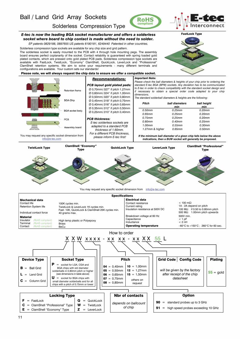
Ball / Land Grid Array Sockets Solderless Compression Type E-tec is now the leading BGA socket manufacturer and offers a solderless socket where board to chip contact is made without the need to solder.
EP patents 0829188, 0897655 US patents 6190181, 6249440 Patented in other countries.
Solderless compression type sockets are available for any chip size and grid pattern. The solderless socket is easily mounted to the PCB with 4 through hole mounting pegs. The assembly board ensures perfect coplanarity of the socket. Contact reliability is guaranteed with spring loaded gold plated contacts, which are pressed onto gold plated PCB pads. Solderless compression type sockets are available with FastLock, TwistLock, “Economy” ClamShell, QuickLock, LeverLock and “Professional” ClamShell retention systems. We aim to solve your requirements - many different terminals and configurations are available. Your custom sets our standards!
Please note, we will always request the chip data to ensure we offer a compatible socket.
FastLock Type
You may request any specific socket dimension from [email protected]
Recommendations:
PCB layout gold plated pads: Ø 0,70mm/.027“ if pitch 1,27mm Ø 0,60mm/.024“ if pitch 1,00mm Ø 0,50mm/.020“ if pitch 0,80mm Ø 0,45mm/.018“ if pitch 0,75mm Ø 0,40mm/.016“ if pitch 0,65mm Ø 0,35mm/.012“ if pitch 0,50mm Ø 0,25mm/.010“ if pitch 0,40mm
PCB thickness:
E-tec solderless sockets are adapted to a standard PCB
thickness of 1.60mm. For a different PCB thickness,
please inform E-tec first!
Important Note: Please check the ball diameters & heights of your chip prior to ordering the standard E-tec BGA (BPW) sockets. Any deviation has to be communicated to E-tec in order to check compatibility with the standard socket design and if necessary to obtain a special order code adapted to your chip dimensions. The standard solderball diameters & heights are the following:
Pitch ball diameters ball height min min 0.50mm 0.25mm 0.20mm 0.65mm 0.25mm 0.20mm 0.75mm 0.25mm 0.20mm 0.80mm 0.40mm 0.25mm 1.00mm 0.55mm 0.30mm 1.27mm & higher 0.65mm 0.50mm
If the minimum ball diameter of a given chip falls below the above indications, then a BUW socket will generally be proposed.
TwistLock Type ClamShell “Economy”
Type QuickLock Type LeverLock Type ClamShell “Professional” Type
You may request any specific socket dimension from [email protected]
Specifications Mechanical data Contact life Retention System life Individual contact force
Material Insulator (RoHS compliant) Terminal (RoHS compliant) Contact (RoHS compliant)
100K cycles min. TwistLock & LeverLock 1K cycles min. Fast- 10K, QuickLock & ClamShell 25K cycles min. 40 grams max.
High temp plastic or Polyepoxy Brass BeCu
Electrical data Contact resistance Current rating Insulation resistance at 500V DC Breakdown voltage at 60 Hz Capacitance Inductance Operating temperature
< 100 mΩ 1A - 2A depend on pitch 100 MΩ if 0.50 to 0.80mm pitch 500 MΩ 1.00mm pitch upwards 500V min. < 1 pF < 2 nH −60°C to +150°C ; 260°C for 60 sec.
How to order
X X W x x x x - x x x x - x x X X 55 L Device Type Socket Type Pitch Grid Code Config Code Plating
B = Ball Grid
L = Land Grid
C = Column Grid
P = socket for LGA, CGA and BGA chips with std diameter
solderballs in 0.80mm pitch or higher (see dimensions in table above)
U = socket for BGA chips with small diameter solderballs and for all chips with a pitch of 0.75mm or lower
04 = 0,40mm 05 = 0,50mm 06 = 0,65mm 07 = 0,75mm 08 = 0,80mm
10 = 1,00mm 12 = 1,27mm 15 = 1,50mm
others on request
will be given by the factory
after receipt of the chip datasheet
55 = gold
Locking Type Nbr of contacts Option F = FastLock C = ClamShell “Professional” Type E = ClamShell “Economy” Type
Q = QuickLock W = TwistLock Z = LeverLock
depends on ballcount
of chip
90 = standard probes up to 3 GHz
91 = high speed probes exceeding 10 GHz
11
BGA/LGA/QFN & GullWing Chip Socket Elastomer Interposer style
E-tec is now the leading BGA socket manufacturer. These elastomer interposer sockets are available for any chip size and pitch. The standard version is the solderless socket style, which is attached with 2 or 4 screws to the PCB. SMT and thru-hole adapter sockets are available in certain pitches (contact factory for availability first) with these elastomer interposers to allow using this high frequency interposer on PCB’s which have already been laid out for SMT or thru-hole sockets. The retainer can be delivered with a center opening for die access and the socket outline will be kept to a minimum and special clearances can be offered to avoid components on the PCB. We aim to solve your requirements - your custom sets our standards!
Please note, we will always request the chip data to ensure we offer a compatible socket.
BGA/LGA/QFN Chip Socket
FastLock Type
GullWing Chip Socket
ScrewLock Type
Solderless Compression style Standard Version
(FastLock Type as example only – other locking systems available also)
gold plated pads Ø 0,70mm/.027“ if pitch 1,27mm gold plated pads Ø 0,60mm/.024“ if pitch 1,00mm gold plated pads Ø 0,50mm/.020“ if pitch 0,80mm gold plated pads Ø 0,45mm/.018“ if pitch 0,75mm gold plated pads Ø 0,40mm/.016“ if pitch 0,65mm gold plated pads Ø 0,30mm/.012“ if pitch 0,50mm
Important Note:
PCB pad height: same or higher then solder mask. PCB thickness: 1.60mm std. (others: contact E-tec)
Elastomer Specifications Flammability UL 94V-0 Current rating at minimum 0.10mm compression depends on solderball size: 0.30mm dia balls 1A min. 0.60mm dia balls 2A min. Insulation resistance : 1000 MΩ Contact resistance : < 50 mΩ Capacitance : <0.3 pF Inductance : <0.6 nH Breakdown voltage : 500V DC Operating temperature : -35°C to +125°C Bandwith
0.50mm thick elastomer sinusoidal signals : -1dB at >10 GHz digital signals: 10 GHz min.
1.00mm thick elastomer sinusoidal signals: -1dB at >10 GHz digital signals: up to 6.5GHz max. Recommended Compression: 0.10mm min. Compression forces
0.50mm thick elastomer Solderball diameters 0.50mm = 40 to 50gf @0.20mm 0.60mm = 60 to 80gf @0.20mm 0.75mm = 90 to 120gf @0.20mm 1.00mm thick elastomer Solderball diameters 0.50mm = 40 to 50gf @0.20mm 0.60mm = 50 to 70gf @0.20mm 0.75mm = 90 to 120gf @0.20mm
Mechanical data Elastomer life BGA chips : 1K cycles min.
LGA/QFN chips : 10K cycles min.
Dimensions & Tolerances Pitch of wires P1& P2 = 0.05mm x 0.05mm to 0.10mm x 0.10mm (depending on pitch of chip) Thickness/Offset T= 0.50mm (±0.05mm)/Offset= 0.25mm (±0.05mm) T= 1.00mm (±0.07mm)/Offset= 0.50mm (±0.07mm) Width/Length min.= 3.00mm x 3.00mm (±0.50mm) max.= 49.00mm x 49.00mm (±0.50mm)
Locking systems overview (not exhaustive) Special Elastomer Adapters (on request)
FastLock
“Economy” ClamShell
TwistLock
QuickLock
SMT and THT (Soldertail) Adapter Style on request
(FastLock Type as example only – other locking systems available also)
Recommendations for SMT Adapter Boards Solder paste Please use a solder paste w/o any silver! Solder profile Please refer to our website www.e-tec.com
How to order
E X X x x x x - x x x x - x x X X x x L locating pegs
Device Type Locking Type Nbr of
contacts
Elastomer or Pitch
Grid Code
Config Code
Plating
B = BGA
L = LGA/QFN
G = GullWing
W = TwistLock F = FastLock Q = QuickLock E = ClamShell “Economy” Type for BGA/LGA/QFN For GullWing type contact factory. Lifetime: TwistLock 1K cycles min. all others 10K cycles min.
999 if LGA or QFN
Ball count if BGA
will be given by the factory after receipt of the
chip datasheet
will be given by the factory after receipt of the chip
datasheet
55 = gold if with adapterboard
95 = tin/gold (tin leadfree)
Contact Type
90 = Solderless Compression Type; 6.5 GHz performance
91 = Solderless Compression Type; 10 GHz performance others on request Solder Adapters (on request only): 30 = SMT……… ( with surface mount Adapterboard )
70 = THT……… ( with soldertail Adapterboard )
12
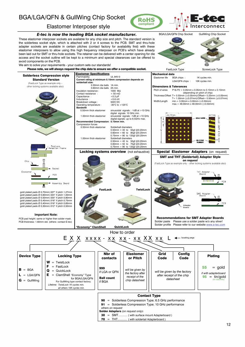
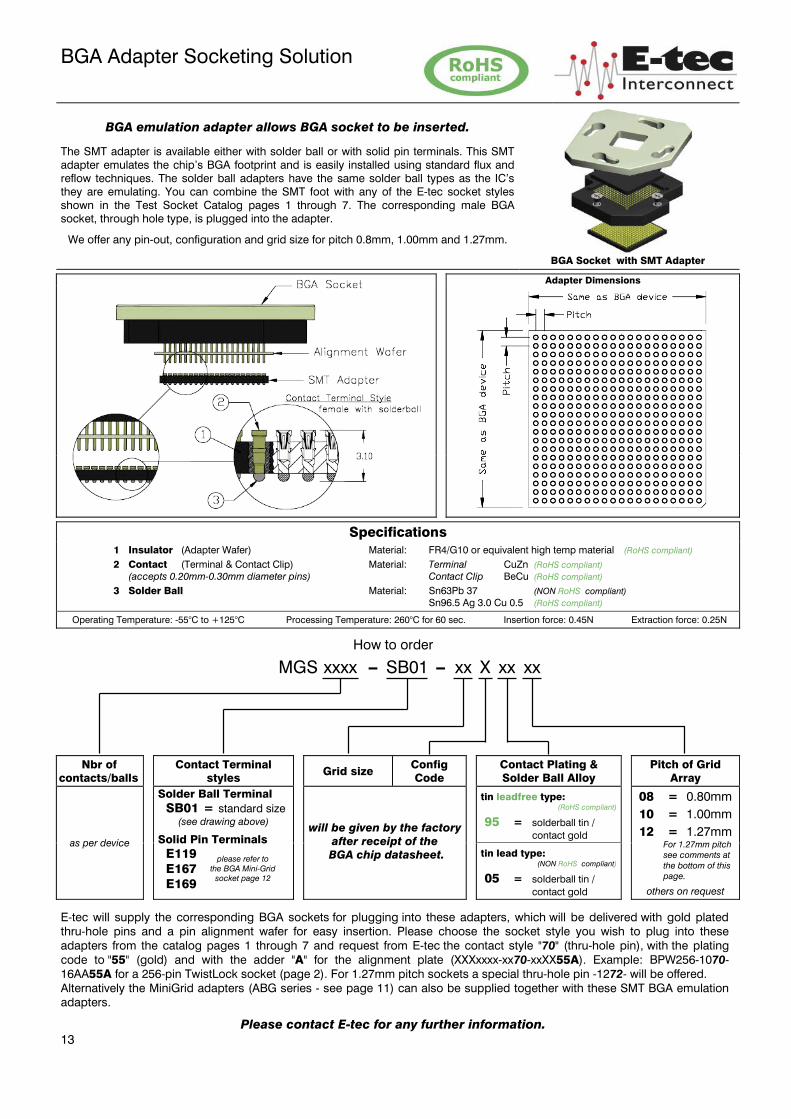
BGA Adapter Socketing Solution
BGA emulation adapter allows BGA socket to be inserted.
The SMT adapter is available either with solder ball or with solid pin terminals. This SMT adapter emulates the chip’s BGA footprint and is easily installed using standard flux and reflow techniques. The solder ball adapters have the same solder ball types as the IC’s they are emulating. You can combine the SMT foot with any of the E-tec socket styles shown in the Test Socket Catalog pages 1 through 7. The corresponding male BGA socket, through hole type, is plugged into the adapter.
We offer any pin-out, configuration and grid size for pitch 0.8mm, 1.00mm and 1.27mm.
BGA Socket with SMT Adapter
Adapter Dimensions
Specifications 1 Insulator (Adapter Wafer) Material: FR4/G10 or equivalent high temp material (RoHS compliant)
2 Contact (Terminal & Contact Clip) Material: Terminal CuZn (RoHS compliant) (accepts 0.20mm-0.30mm diameter pins) Contact Clip BeCu (RoHS compliant)
3 Solder Ball Material: Sn63Pb 37 (NON RoHS compliant) Sn96.5 Ag 3.0 Cu 0.5 (RoHS compliant)
Operating Temperature: -55°C to +125°C Processing Temperature: 260°C for 60 sec. Insertion force: 0.45N Extraction force: 0.25N
How to order
MGS xxxx – SB01 – xx X xx xx
Nbr of contacts/balls
Contact Terminal styles
Grid size Config Code
Contact Plating & Solder Ball Alloy
Pitch of Grid Array
as per device
Solder Ball Terminal SB01 = standard size
(see drawing above)
Solid Pin Terminals E119 E167 E169
will be given by the factory after receipt of the
BGA chip datasheet.
tin leadfree type: (RoHS compliant)
95 = solderball tin / contact gold
08 = 0.80mm 10 = 1.00mm 12 = 1.27mm
For 1.27mm pitch see comments at the bottom of this page.
others on request
tin lead type: (NON RoHS compliant)
05 = solderball tin / contact gold
E-tec will supply the corresponding BGA sockets for plugging into these adapters, which will be delivered with gold plated thru-hole pins and a pin alignment wafer for easy insertion. Please choose the socket style you wish to plug into these adapters from the catalog pages 1 through 7 and request from E-tec the contact style "70" (thru-hole pin), with the plating code to "55" (gold) and with the adder "A" for the alignment plate (XXXxxxx-xx70-xxXX55A). Example: BPW256-1070-16AA55A for a 256-pin TwistLock socket (page 2). For 1.27mm pitch sockets a special thru-hole pin -1272- will be offered. Alternatively the MiniGrid adapters (ABG series - see page 11) can also be supplied together with these SMT BGA emulation adapters.
Please contact E-tec for any further information. 13
please refer to the BGA Mini-Grid
socket page 12
BGA Solder Adapter
The E-tec BGA Adapter System comprises two elements, the BGA solder adapter onto which the BGA chip is soldered (converting the BGA chip to a PGA), and the MiniGrid Socket which is soldered to the PCB. The solder adapter can then be
plugged into the MiniGrid Socket ( page 10 or 12 ).
E-tec offers any pin-out, configuration and grid size.
Special terminal designs are possible on request.
Terminal styles
Type 116 Standard for 1,27mm pitch
Type 158 Optional for 1,27mm pitch
Type 168 if 1,00mm pitch
Type 175 if 0,80mm pitch
Specifications
Terminal Type Material Plating Adapter Others 116, 158, 168 & 175 CuZn Au over Ni over Cu Material : FR 4 glass Epoxy UL 94V-0 Operating Temperature : −55°C to +125°C ; 260°C for 60 sec.
How to order
ABG xxxx - E xxx - xx X 55 xx Nbr of
contacts / balls Terminal
style Grid size Config
Code Plating Pitch of
Grid Array
as per device
Please refer
to the
drawings
shown above
will be given by the
factory after receipt of
the BGA chip datasheet
55 = gold
08 = 0.80mm
10 = 1.00mm
12 = 1.27mm
15 = 1.50mm
others on request
14
BGA Chip
Solder Adapter MiniGrid Socket
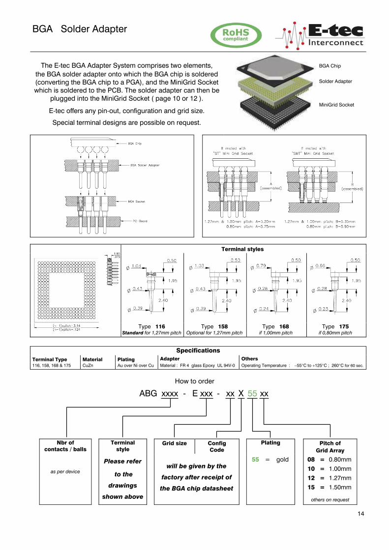

BGA MiniGrid Socket
The E-tec MiniGrid Socket is soldered to the target board and is designed to accept the BGA Solder Adapter (where the chip is soldered to the adapter board). As an alternative, this MiniGrid Socket is also designed to accept the “true” through hole BGA Sockets (where the chips can be socketed without soldering).
E-tec offers any pin-out, configuration and grid size. Special terminal designs are possible on request.
Terminal styles
SMT Terminal
Type 119 if 1,27 ; 1,50 & 2,00mm pitch
SMT „floating”
Type 120 if 1,27 ; 1,50 & 2,00mm pitch
SMT
Terminal
Type 167 if 1,00mm pitch
SMT
Terminal
Type 169 if 0,80mm pitch
Soldertail Type
Soldertail Terminal
Type 117 if 1,27 ; 1,50 & 2,00mm pitch
Soldertail Terminal
Type 172 if 1,00mm pitch
Soldertail Terminal
Type 174 if 0,80mm pitch
Specifications Terminal Type Material Plating Socket Others 117, 119, 120, 167 169, 172, 174
Terminal : CuZn Contact clip : BeCu
Sn over Ni over Cu Au over Ni over Cu
Material Operating Temperature FR 4 glass Epoxy UL 94V-0 −55°C to +125°C ; 260°C for 60 sec.
How to order
MGS xxxx - E xxx - xx X 95 xx
Nbr of contacts
Terminal styles Grid size Config Code
Plating
Pitch of Grid Array
as per device
Please refer to the drawings shown above.
For solderball MiniGrid Sockets please refer to page 10.
will be given by the factory after receipt of the chip
datasheet.
95 = tin/gold (tin leadfree)
08 = 0.80mm 10 = 1.00mm 12 = 1.27mm 15 = 1.50mm 20 = 2.00mm
others on request
15
QFN / MLF / MLP Socket TwistLock, FastLock, QuickLock & ClamShell Type
E-tec is now the leading BGA socket manufacturer. EP patents 0829188, 0897655 US patents 6190181, 6249440 Patented in other countries.
QFN/MLF/MLP sockets are available for any chip size and pitch. They are available in SMT, thru-hole and solderless compression type versions. The SMT socket is simply placed and reflowed onto the PCB in the same way as the chip and it only requires a small amount of additional board space. The retainer can be delivered with a center opening for die access. Additional center grounding pins are offered on request. We aim to solve your requirements - your custom sets our standards!
Please note, we will always request the chip data to ensure we offer a compatible socket.
FastLock Type
SMT style
Ø 0,60mm/.024” if pitch 1,27mm Ø 0,50mm/.020” if pitch 1,00mm Ø 0,40mm/.016” if pitch 0,80mm Ø 0,35mm/.014” if pitch 0,75mm Ø 0,35mm/.014” if pitch 0,65mm Ø 0,30mm/.012” if pitch 0,50mm
Soldertail style Solderless Compression style (TwistLock Type as example shown)
Soldertail dimension:
Ø 0,42mm/.016” if pitch 1,27mm Ø 0,29mm/.011” if pitch 1,00mm Ø 0,29mm/.011” if pitch 0,80mm Ø 0,27mm/.010” if pitch 0,75mm Ø 0,27mm/.010” if pitch 0,65mm Ø 0,27mm/.010” if pitch 0,50mm Ø 0,17mm/.007” if pitch 0,40mm
PCB solder hole:
Ø 0,60mm/.024” if pitch 1,27mm Ø 0,50mm/.020” if pitch 1,00mm Ø 0,40mm/.016” if pitch 0,80mm Ø 0,35mm/.014” if pitch 0,75mm Ø 0,35mm/.014” if pitch 0,65mm Ø 0,35mm/.014” if pitch 0,50mm Ø 0,25mm/.010” if pitch 0,40mm
PCB Pad Layout
You may request any specific socket dimension from [email protected] gold plated pads Ø 0,70mm/.027” if pitch 1,27mm gold plated pads Ø 0,60mm/.024” if pitch 1,00mm gold plated pads Ø 0,50mm/.020” if pitch 0,80mm gold plated pads Ø 0,45mm/.018” if pitch 0,75mm gold plated pads Ø 0,40mm/.016” if pitch 0,65mm gold plated pads Ø 0,35mm/.012” if pitch 0,50mm gold plated pads Ø 0,25mm/.010” if pitch 0,40mm
Specifications Mechanical data
Contact life Retention System life TwistLock FastLock ClamShell & QuickLock Solderability Individual contact force
Material Insulator (RoHS compliant) Terminal (RoHS compliant) Contact (RoHS compliant)
Electrical data Contact resistance Current rating Insulation resistance at 500V DC Breakdown voltage at 60 Hz Capacitance Inductance Operating temperature
100K cycles min. 1K cycles min. 10K cycles min. 25K cycles min. as per IEC 60068-2-58 40 grams max.
High temp plastic or Polyepoxy Brass BeCu
< 100 mΩ 1A - 2A depend on pitch 100 MΩ if 0.50 to 0.80mm pitch 500 MΩ 1.00mm pitch upwards 500V min. < 1 pF < 2 nH
−60°C to +150°C ; 260°C for 60 sec.
Recommendations: Solder paste – Please use a solder paste w/o any silver! Solder profile – Please refer to our website www.e-tec.com
E-tec solderless sockets are adapted to a standard PCB thickness of 1.60mm. For a different PCB thickness, please inform E-tec first! SMT sockets are recommended to be ordered with locating pegs for soldering to the PCB, to avoid the solderjoints from being stressed due to the torque forces applied
with this locking system. If used without locating pegs, the life cycle of the socket may be heavily reduced.
How to order
L Q X x x x x - x x x x - x x X X x x L optional for locating pegs
Locking Type Nbr of contacts Pitch Grid Code Config Code Plating
W = TwistLock F = FastLock Q = QuickLock E = ClamShell “Economy” Type N = ClamShell “open” Type
J = ClamShell “open + button” Type
Others on request
depends on landcount of chip,
plus center grounding pins
if required. (generally 4 pins)
04 = 0,40mm 05 = 0,50mm 06 = 0,65mm 07 = 0,75mm 08 = 0,80mm
10 = 1,00mm 12 = 1,27mm
Others on request
will be given by the factory after receipt of the chip datasheet
95 = tin/gold (tin leadfree)
55 = gold only for solderless Compression Type
Contact Type 30 = standard SMT….( „A“ = 1,20mm if 1,27mm pitch; 0,80mm if 1,00mm pitch, 0.60 if 0,80mm pitch; 0,40mm if <0.80mm pitch )
29 = raised SMT…( „A“ = 5,00mm if 1,27mm pitch; 3,20mm if 1,00mm pitch; 2,80mm if 0,80mm pitch, 2.30mm if <0.80mm pitch )
28 = special raised SMT - only for 1.00 & 0.80mm pitch…..... ( „A“ = 4,50mm )
70 = standard solder tail……………….( „A“ = 3.30 if 1.27mm pitch, 2.80 if 1.00mm or 0.80mm pitch, 2,30mm if <0.80mm pitch)
90 & 91 = compression type (see page 8 for more details)
16
TwistLock Solderless Compression Type
QuickLock Type
FastLock Solderless Compression Type
ClamShell
“Economy” Type
ClamShell “Aluminum” Type
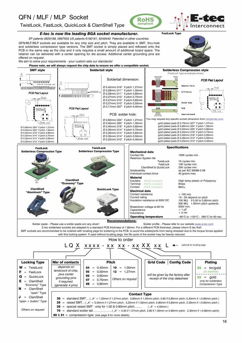

”GullWing Chip” Sockets
Screw-, Fast-, QuickLock & ClamShell Type GullWing sockets are available for any GullWing type chips (QFP, PQFP, SOIC, SO etc.) and lead pattern. The sockets are available for any pin-out and tip-to-tip dimension as of 0.50mm pitch upwards. The SMT socket is simply placed and reflowed onto the PCB in the same way as the chip and it only requires a small amount of additional board space. The standard locking system is the ScrewLock design, but QuickLock and ClamShell locking systems are also available. We aim to solve your requirements - many different terminals and configurations are available. Your custom sets our standards!
Please note, we will always request the chip data to ensure we offer a compatible socket.
ScrewLock Type
SMT style
PCB Pad Layout
Ø 0,50mm/.020“ if pitch 1,27mm Ø 0,50mm/.020“ if pitch 1,00mm Ø 0,40mm/.016“ if pitch 0,80mm Ø 0,35mm/.014“ if pitch 0,75mm Ø 0,35mm/.014“ if pitch 0,65mm Ø 0,30mm/.012“ if pitch 0,50mm
Soldertail style Solderless Compression style
Soldertail dimension: Ø 0,29mm/.011” if pitch 1,27mm Ø 0,29mm/.011” if pitch 1,00mm Ø 0,29mm/.011” if pitch 0,80mm Ø 0,27mm/.010” if pitch 0,75mm Ø 0,27mm/.010” if pitch 0,65mm Ø 0,27mm/.010” if pitch 0,50mm
PCB Hole Layout
PCB solder hole:
Ø 0,50mm/.020” if pitch 1,27mm Ø 0,50mm/.020” if pitch 1,00mm Ø 0,40mm/.016” if pitch 0,80mm Ø 0,35mm/.014” if pitch 0,75mm Ø 0,35mm/.014” if pitch 0,65mm Ø 0,35mm/.014” if pitch 0,50mm
You may request any specific socket dimension from [email protected] gold plated pads Ø 0,60mm/.024“ if pitch 1,27mm gold plated pads Ø 0,60mm/.024“ if pitch 1,00mm gold plated pads Ø 0,50mm/.020“ if pitch 0,80mm gold plated pads Ø 0,45mm/.018“ if pitch 0,75mm gold plated pads Ø 0,40mm/.016“ if pitch 0,65mm gold plated pads Ø 0,35mm/.012“ if pitch 0,50mm
Quick Lock Type FastLock Type ClamShell Type Specifications
without lever for
low leadcount chips
with lever for
high leadcount chips
adapted to low
and high leadcount chips
with center screw for high
leadcount chips
Mechanical data Contact life Retention System life ScrewLock FastLock ClamShell & QuickLock Solderability Individual contact force
Material Insulator (RoHS compliant) Terminal (RoHS compliant) Contact (RoHS compliant)
Electrical data Contact resistance Current rating Insulation resistance at 500V DC Breakdown voltage at 60 Hz Capacitance Inductance
Operating temperature
100K cycles min. 1K cycles min. 10K cycles min. 25K cycles min. as per IEC 60068-2-58 40 grams max.
High temp plastic or Polyepoxy Brass BeCu
< 100 mΩ 1A - 2A depend on pitch 100 MΩ if 0.50 to 0.80mm pitch 500 MΩ 1.00mm pitch upwards 500V min. < 1 pF < 2 nH
−60°C to +150°C ; 260°C for 60 sec.
Recommendations: Solder paste – Please use a solder paste w/o any silver! Solder profile – Please refer to our website www.e-tec.com E-tec solderless sockets are adapted to a standard PCB thickness of 1.60mm. For a different PCB thickness, please inform E-tec first! The SMT sockets are mounted with straight SMT pins (not bent legs), which are adapted to round PCB pads. For rectangular PCB pads, please ensure that the round socket pins will be surface mountable, since E-tec cannot offer any guarantee in such instances. For SMT sockets in general, E-tec recommends the use of locating pegs, which can be soldered to the PCB for added mechanical strength.
How to order
QF X x x x x - x x x x - x x X X x x L optional for locating pegs Retention Type Nbr of contacts Pitch Grid Code Config Code Plating
W = ScrewLock
F = FastLock
Q = QuickLock
C = ClamShell
depends on leadcount of chip
05 = 0,50mm 63 = 0,635mm 06 = 0,65mm 07 = 0,75mm
08 = 0,80mm 10 = 1,00mm 12 = 1,27mm
others on request
will be given by the factory after receipt of the chip
datasheet
95 = tin/gold (tin leadfree)
55 = gold only for solderless Compression Type
Contact Type
30 = standard SMT….( „A“ = 0,80mm if 1,27mm pitch or 1,00mm pitch, 0.60 if 0,80mm pitch; 0,40mm if <0.80mm pitch )
29 = raised SMT…( „A“ = 3,20mm if 1,27mm pitch or 1,00mm pitch; 2,80mm if 0,80mm pitch, 2.30mm if <0.80mm pitch )
28 = special raised SMT - only for 1,27, 1.00 & 0.80mm pitch….....( „A“ = 4,50mm )
70 = standard solder tail……………….( „A“ = 2,80 if 1.27mm pitch, 1.00mm or 0.80mm pitch; 2,30mm if <0.80mm pitch)
90 & 91 = compression type (see page 8 for more details) 17
BGA Socket Accessories & Special Features
Heatsinks for BGA & LGA sockets
Standard & customized Heatsinks (with or without integrated fan) adapted to BGA & LGA sockets are available on request
For order code please contact www.e-tec.com
LGA to BGA converter plates For applications where a chip is tested with & without solderballs the LGA sockets can be delivered with a converter plate to allow
socketing BGA chips with an LGA socket.
For order code please contact www.e-tec.com
Thermo couple attachment feature E-tec TwistLock sockets are available with a thermo couple
attachment feature on request
For order code please contact www.e-tec.com
“Torque Limiting Screwdriver Kit” for E-tec BGA “TwistLock Sockets”
E-tec recommends the use of this pre-set adjustable torque screw driver for correct tightening of the E-tec BGA/LGA socket retention frames. Excess tightening can be completely avoided with the use of this screw driver, which comes with a stainless steel shaft and
attractive coloured aluminium handle.
Special clearances in socket body and stiffener boards
If you need any special clearance for components on the PCB (top side or bottom side), E-tec can easily adapt the socket to
your requirements.
Socket body with clearances Assembly/stiffener board with clearances
For order code please contact www.e-tec.com
The Kit includes:
1 – Torque Limiting Screwdriver
1 – 0 Point Philips Bit 1-15/16“
Order Code:
TOL – 7CN – TORQUE
“Torque Tool Fixture” for E-tec BGA “FastLock Sockets”
For order code please contact www.e-tec.com
Socket with “interchangeable” chip positioning frames For chips with same pincount, but different body sizes, E-tec
offers interchangeable chip positioning frames to allow the use of one single socket.
interchangeable positioning frames
For order code please contact www.e-tec.com
Ultra slim socket profile In case of limited space on the PCB, E-tec can reduce the socket
size to a minimum, based on customer request.
For order code please contact www.e-tec.com
Contact E-tec for any other special feature you may require with the sockets. We will attempt to fulfil your needs!
18

ZIF Test Sockets for Flex Cable
0.50mm to 2.54mm pitch
High cycle ZIF Test Sockets for any kind and pitch of Flex-Cable.
Handles up to 10k cycles with simple open/close ClamShell type retention frame.
Cable Dimensions
In order to be able to offer the correct socket for your cable, we need to know the type of cable you are using and the corresponding dimensions
as shown below. Please send the datasheet of your cable together with your socket request.
Specifications Mechanical data Contact life Retention System life Solderability Individual contact force
Material Insulator (RoHS compliant) Terminal (RoHS compliant) Spring (RoHS compliant) Electrical data Contact resistance Current rating Insulation resistance at 500V DC Breakdown voltage at 60 Hz Capacitance Inductance
Operating temperature Processing temperature
100K cycles min. 10K cycles min. as per IEC 60068-2-58 40 grams max.
High temp plastic or Polyepoxy Brass BeCu < 100 mΩ 1A - 2A depend on pitch 100 MΩ if 0.50 to 0.80mm pitch 500 MΩ 1.00mm pitch upwards 500V min. < 1 pF < 2 nH
−60°C to +150°C 260°C for 60sec.
A detailed socket drawing with the required PCB layout dimensions will be submitted by E-tec for each project.
How to order
FCT - x xx - X xxx - xx
Pitch Nbr of conductors Socket Type Execution Plating
1 = 0.50mm 2 = 0.80mm 3 = 1.00mm 4 = 1.25mm 5 = 1.27mm 6 = 2.00mm 7 = 2.54mm
02 to 40
T = THT (soldertail)
S = SMT (surface mount)
C = Compression Type (solderless)
000 = standard (will be given by the factory)
95 = tin/gold (leadfree)
55 = gold only for solderless Compression Type
19
Other products from E-tec
Please contact your closest sales office for further information.
Insertion- Extraxtion Tools IC - Sockets Switches
Compact Flash Connectors USB & IEEE 1394 Connectors Mini PCI Express Connectors
D-Sub Connectors Flex Cable Connectors HDMI Connectors
Probe Pin & Probe Pin Connectors PCB Connectors Multi Media Card Connectors
Modular Plugs & Jacks Phono - & DC - Power Connectors RF - Connectors
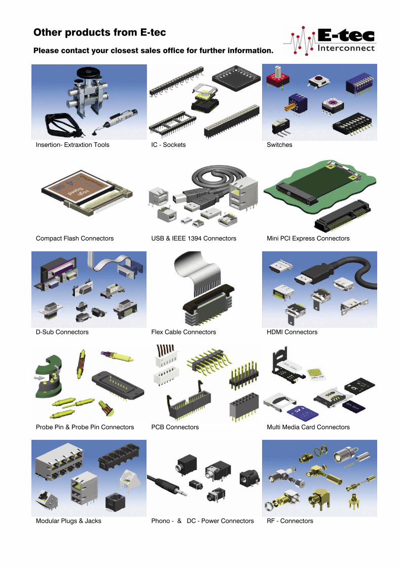

ww
w.e
-tec.
com
TEST SOCKETS & ADAPTERS02TEST SOCKETS & ADAPTERS02TEST SOCKETS & ADAPTERS
ww
w.e
-tec.
com
D-SUB & I/O CONNECTORSPCB
INTERCONNECT PRODUCTS
ww
w.e
-tec.
com
ww
w.e
-tec.
com
DIP & ROTARY SWITCH
ww
w.e
-tec.
com
TEST SOCKETS & ADAPTERS
ww
w.e
-tec.
com
IC-SOCKETS &INTERCONNECT PRODUCTS
International Sales Headquarters
Switzerland E-tec Interconnect Ltd. Schweiz Zone Industrielle CSuisse CH-1072 Forel (Lavaux) Phone: +41 / 21 / 781 08 10 Fax: +41 / 21 / 781 08 11 e-mail: [email protected] www.e-tec.com
Related Sales Headquarters
Deutschland EMC electro mechanical componentsGermany Vertriebs GmbHAllemagne PF. 1160 D-65501 Idstein Phone: +49 / 61 26 / 93 95 - 0 Fax: +49 / 61 26 / 93 95 - 72 e-mail: [email protected] www.emc-connectors.com
France Silfox SAFrankreich PA des Petits Carreaux 2 bis avenue des Coquelicots F-94385 BONNEUIL SUR MARNE CEDEX Phone: +33 / 1 / 49 56 04 68 Fax: +33 / 1 / 49 56 02 87 e-mail: [email protected] www.silfox.fr
England E-tec Interconnect (UK) Ltd.Angleterre Units A5 & A6 Decimus Park Kingstanding Way Tunbridge Wells Kent TN2 3GP Phone: +44 / 18 92 / 53 02 60 Fax: +44 / 18 92 / 51 55 60 e-mail: [email protected] www.e-tec.co.uk
Factories
Switzerland E-tec AG Schweiz Friedhofstrasse 1Suisse CH-2543 Lengnau b. Biel Phone: +41 / 32 / 6 54 15 50 Fax: +41 / 32 / 6 52 26 93 e-mail: [email protected] www.e-tec.com
Taiwan E-tec Interconnect Asia Ltd. 10F-2, No. 379, Jhongshan Road SANCHONG Dist. New Taipei City Taiwan R.O.C. Phone: +886 / 2 / 29992726 Fax: +886 / 2 / 29995255 e-mail: [email protected] www.e-tec-asia.com.tw
ww
w.e
-tec.
com
D-SUB & I/O CONNECTORSPCB
INTERCONNECT PRODUCTS
ww
w.e
-tec.
com
ww
w.e
-tec.
com
DIP & ROTARY SWITCH
YOUR AUTHORISED DISTRIBUTORIHR VERTRAGS-DISTRIBUTORVOTRE DISTRIBUTEUR OFFICIEL
e-tec-Prospekt-Titelseiten.indd 2-3 23.05.11 11:10
YOUR AUTHORISED DISTRIBUTORIHR VERTRAGS-DISTRIBUTORVOTRE DISTRIBUTEUR OFFICIEL
0707PCBINTERCONNECT PRODUCTS
ww
w.e
-tec.
com
International Sales Headquarters
Switzerland E-tec Interconnect Ltd. Schweiz Zone Industrielle CSuisse CH-1072 Forel (Lavaux) Phone: +41 / 21 / 781 08 10 Fax: +41 / 21 / 781 08 11 e-mail: [email protected] www.e-tec.com
Related Sales Headquarters
Deutschland EMC electro mechanical componentsGermany Vertriebs GmbHAllemagne PF. 1160 D-65501 Idstein Phone: +49 / 61 26 / 93 95 - 0 Fax: +49 / 61 26 / 93 95 - 72 e-mail: [email protected] www.emc-connectors.com
France Silfox SAFrankreich PA des Petits Carreaux 2 bis avenue des Coquelicots F-94385 BONNEUIL SUR MARNE CEDEX Phone: +33 / 1 / 49 56 04 68 Fax: +33 / 1 / 49 56 02 87 e-mail: [email protected] www.silfox.fr
England E-tec Interconnect (UK) Ltd.Angleterre Units A5 & A6 Decimus Park Kingstanding Way Tunbridge Wells Kent TN2 3GP Phone: +44 / 18 92 / 53 02 60 Fax: +44 / 18 92 / 51 55 60 e-mail: [email protected] www.e-tec.co.uk
Factories
Switzerland HAPP AG / E-tec AG Schweiz Friedhofstrasse 1Suisse CH-2543 Lengnau b. Biel Phone: +41 / 32 / 6 54 15 50 Fax: +41 / 32 / 6 52 26 93 e-mail: [email protected] www.e-tec.com
Taiwan HAPP & E-tec Taiwan Ltd. 10-2F, No. 379, Zhong Shan Road San Chong City, Taipei Hsien TAIWAN Phone: +886 / 2 / 29 99 - 27 26 Fax: +886 / 2 / 29 99 - 52 55 e-mail: [email protected] www.happetec.com.tw
ww
w.e
-tec.
com
D-SUB & I/O CONNECTORS
ww
w.e
-tec.
com
DIP & ROTARY SWITCH
ww
w.e
-tec.
com
IC-SOCKETS &INTERCONNECT PRODUCTS
YOUR AUTHORISED DISTRIBUTORIHR VERTRAGS-DISTRIBUTORVOTRE DISTRIBUTEUR OFFICIEL
International Sales Headquarters and Factory
Switzerland E-tec Interconnect AGSchweiz Friedhofstrasse 1Suisse CH-2543 Lengnau b. Biel Phone: +41 (0) 32 654 15 50 Fax: +41 (0) 32 652 26 93 Email: [email protected] Web: www.e-tec.com
Factory
Taiwan E-tec Interconnect Asia Ltd. 10-2F, No. 260, Section 2, New Taipei Blvd., Sanchong Dist. 24158 New Taipei City TAIWAN Phone: +886 / 2 2999 2726 Fax: +886 / 2 2999 5255 Email: [email protected] Web: www.e-tec-asia.com.tw
Related Sales Headquarters
Deutschland EMC electro mechanical components GmbHGermany Deningerstrasse 4aAllemagne D-65510 Idstein Phone: +49 (0) 6126 / 93 95-0 Fax: +49 (0) 6126 / 93 95-72 Email: [email protected] Web: www.emc.de
England E-tec Interconnect UK LtdAngleterre Units A5 & A6 Decimus Park Kingstanding Way Tunbridge Wells Kent TN2 3GP Phone: +44 / 18 92 / 53 02 60 Fax: +44 / 18 92 / 51 55 60 Email: [email protected] Web: www.e-tec.co.uk
USA/Canada E-tec Interconnect USA (TopLine Corporation) 95 Highway 22 W. Milledgeville, GA 31061 Phone: +1-478-451-5000 Fax: +1-478-451-3000 Email: [email protected] Web: www.e-tec.us.com
France Silfox SAFrankreich Ecolope-Zac le Charme 245 Avenue de Rio F-77550 Moissy Cramayel Phone: +33 / 1 / 49 56 04 68 Fax: +33 / 1 / 49 56 02 87 Email: [email protected] Web: www.silfox.fr
The E-tec Group
e-tec-Prospekt-Titelseiten.indd Alle Seiten 18.10.16 16:56