Embed Size (px)
Citation preview

SVERIGES LANTBRUKSUNIVERSITET
1 Input files 11 Switches Ilparameters 11 Outputs 11 Execute 1 I Technical
Model specific
Henrik Eckersten
Institutionen for markvetenskap Avdelningsmeddelande 91:3 Avdelningen for lantbrukets hydroteknik Communications
Swedish University of Agricultural Sciences Uppsala 1991 Department of Soil Sciences ISSN 0282-6569
Division of Agricultural Hydrotechnics ISRN SLU-HY-AVDM--91/3--SE
Denna serie meddelanden utges av Avdelningen for lantbrukets hydroteknik, Sveriges Lantbruksuniversitet, Uppsala. Serien inneMller sadana forsknings- och forsoksredogorelser samt andra uppsatser som bedoms vara av i forsta hand i nternt intresse. Uppsatser lampade for en mer allman spridning publiceras bl a i avdelningens rapportserie. Tidigare nummer i meddelandeserien kan i man av tillgang levereras fran avdelningen.
Distribution:
Sveriges Lantbruksuniversitet I nstitutionen for markvetenskap Avdelningen for lantbrukets hydroteknik Box 7014 75007 UPPSALA
Tel. 018-6711 69,6711 81
This series of Communications is produced by the Division of Agricultural Hydrotechnics, Swedish University of Agricultural Sciences, Uppsala. The series concists of reports on research and field trials and of other articles considered to be of interest mainly within the department. Articles of more general interest are published in, for example, the department's Report series. Earlier issues in the Communications series can be obtained from the Division of Agricultural Hydrotechnics (subject to availability) .
Swedish University of Agricultural Sciences Department of Soil Sciences Division of Agricultural Hydrotechnics P.O. Box 7014 S-750 07 UPPSALA, SWEDEN
Tel. +46-(18) 6711 69, +46-(18) 6711 81
SVERIGES LANTBRUKSUNIVERSITET
I 1 Input files 11 Switches Ilparameters 1 1 Outputs 11 Execute 1 J Technical
Model specific
Henrik Eckersten
Institutionen for markvetenskap Avdelningsmeddelande 91:3 Avdelningen for lantbrukets hydroteknik Communications
Swedish University of Agricultural Sciences Uppsala 1991 Department of Soil Sciences (SSN 0282-6569
Division of Agricultural Hydrotechnics (SRN SLU-HY-AVOM--91/3--SE


Table of Contents
1 Background ....... ............ .............. ... ........ ......... ....... ....... ........... ........... ......... 5
2 Getting started .............................................................................................. 6 2.1 Installation ............ ............ ............. ......... ........ ....... ...... .... ............ .......... 6 2.2 Files ...................................................................................................... 6 2.3 Demonstration example ........ ......... ........... ...... ........ ...... ................ ........ 6 2.4 Running the model...... ............... ........ ........ ....... ....... ........... ...... ......... ... 6 2.5 Evaluating your simulation ........... .......... ....... ...... ...... ...... ...... ........... ..... 7
3 Program structure ............ ............... ......... ........ ...... .............. .................... ..... 7
4 Input files ...................................................................................................... 7 4.1 Driving variable file ............................................................................... 7 4.2 Parameter file ............. ... ............ ........ .......... ...... ....... ..... ............... ....... 7 4.3 Translation file ...................................................................................... 7 4.4 Initial states file ..................................................................................... 7 4.5 Final states file ..................................................................................... 8 4.6 Output file ............................................................................................. 8 4.7 Validation file ........................................................................................ 8 4.8 Other initial files ................................................................................... 8 4.9 General file description ............. .............. ................... ........ ....... ............ 8
5 Run options ................................................................................................... 10 5.1 Run no.: ............. .................. .......... .......... ................ ..... ......... ......... ...... 10 5.2 Start date: ............................................................................................. 10 5.3 Output interval: ..................................................................................... 10 5.4 No of iterations: ..................................................................................... 10 5.5 Run id: .................................................................................................. 10 5.6 Comment: ............................................................................................. 10
6 Execute ......................................................................................................... 1 0 6.1 Exit ........................................................................................................ 10 6.2 Run ....................................................................................................... 10 6.3 Write a parameter file ........................................................................... 11
7 Warnings and Errors of parameter values ........... .......... ............................... 11
8 Commands .... ......................... ............ .................... ......... ................... .......... 11
9 Problems ....................................................................................................... 12
10 Help ............................................................................................................ 12
11 References ................... ............................................... ............................... 12
12 SWITCHES .............. ...................... .................................................. ........... 13 12.1 Technical ............................................................................................ 13 12.2 Model Specific .................................................................................... 15
13 PARAMETERS ........................................................................................... 17 13.1 Start .................................................................................................... 17 13.2 Photosynthesis .... ................ ........... ................ .................................... 19 13.3 C allocation ........................................................................................ 20 13.4 N=allocation ........................................................................................ 21
13.5 N_availability ....................................................................................... 21 13.6 Decomposition .................................................................................... 21 13.7 Temperature_etc ................................................................................ 22 13.8 Water ......... ..... ........ ........ .......... .... ............. ...... ...... .......... ..... .... ...... .... 22 13.9 Sensitivity.. ........ ....... ... .... ........ ......... ......... ... ..... ...... ................... ......... 23 13.10 Plotting_on_line ....... ...... ........ ........ ..... ..... ..... .......... .......... ....... ......... 24
14 OUTPUTS .... ........ ..... ...... ... ....... ........ ....... .......... ........ ........ ......... ........... ..... 25 14.1 State variables .................................................................................... 25 14.2 Flow variables ..................................................................................... 26 14.3 Auxiliary variables ....... ......... ........ .......... .......... ....... .......... ............ ...... 26 14.4 Driving variables ................................................................................. 28 14.5 Annual sums .. ........ ......... ........ ....... .......... ......... .......... .......... ............ 28 14.6 Other variables calculated .................................................................. 29
15 News ........................................................................................................... 31
1 Background
Uppsala 91-10-29
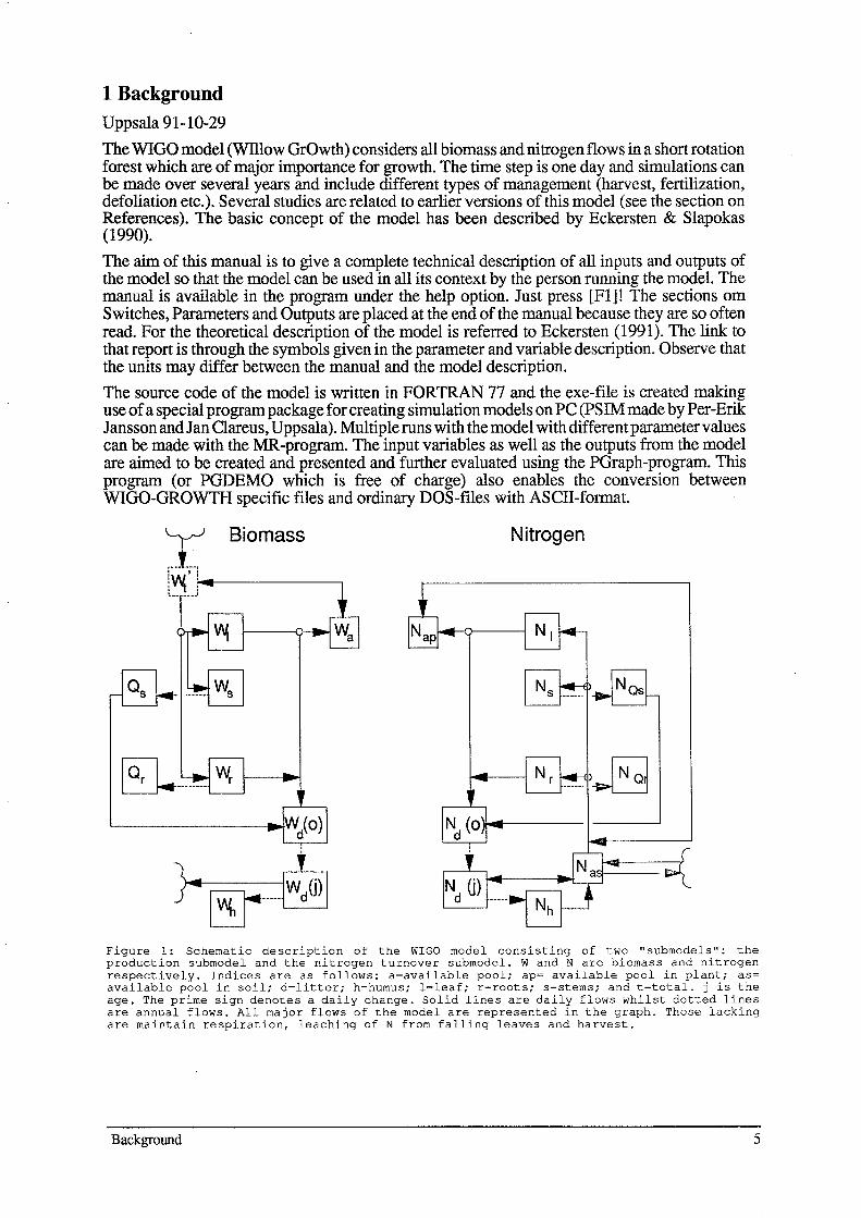
The WIGO model (WIllow GrOwth) considers all biomass and nitrogen flows in a short rotation forest which are of major importance for growth. The time step is one day and simulations can be made over several years and include different types of management (harvest, fertilization, defoliation etc.). Several studies are related to earlier versions of this model (see the section on References). The basic concept of the model has been described by Eckersten & Slapokas (1990).
The aim of this manual is to give a complete technical description of all inputs and outputs of the model so that the model can be used in all its context by the person running the model. The manual is available in the program under the help option. Just press [Fl]! The sections om Switches, Parameters and Outputs are placed at the end of the manual because they are so often read. For the theoretical description of the model is referred to Eckersten (1991). The link to that report is through the symbols given in the parameter and variable description. Observe that the units may differ between the manual and the model description. The source code of the model is written in FORTRAN 77 and the exe-file is created making use of a special program package for creating simulation models on PC (PSIM made by Per-Erik J ansson and J an Clareus, Uppsala). Multiple runs with the model with different parameter values can be made with the MR-program. The input variables as well as the outputs from the model are aimed to be created and presented and further evaluated using the PGraph-program. This program (or PGDEMO which is free of charge) also enables the conversion between WIGO-GROWTH specific files and ordinary DOS-files with ASCII-format.
Biomass Nitrogen
Figure 1: Schematic description of the WIGO model consisting of two "submodels": the production submodel and the nitrogen turnover submodel. Wand N are biomass and nitrogen respectively. Indices are as follows: a=available pool; ap= available pool in plant; as= available pool in soil; d=litter; h=humus; l=leaf; r=roots; s=stems; and t=total. j is the age. The prime sign denotes a daily change. Solid lines are daily flows whilst dotted lines are annual flows. All major flows of the model are represented in the graph. Those lacking are maintain respiration, leaching of N from falling leaves and harvest.
Background 5
2 Getting started
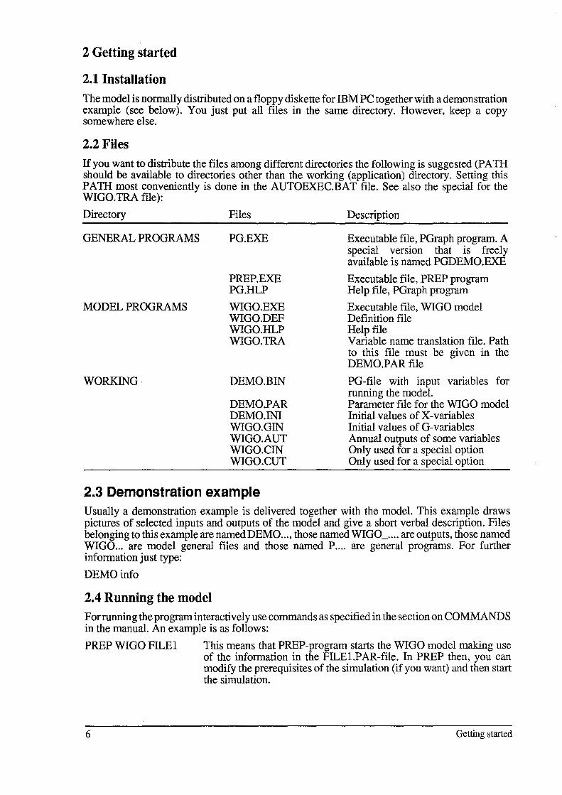
2.1 Installation The model is normally distributed on a floppy diskette for IBM PC together with a demonstration example (see below). You just put all files in the same directory. However, keep a copy somewhere else.
2.2 Files If you want to distribute the files among different directories the following is suggested (PATH should be available to directories other than the working (application) directory. Setting this PATH most conveniently is done in the AUTOEXEC.BAT file. See also the special for the WIGO.TRA file):
Directory
GENERAL PROGRAMS
MODEL PROGRAMS
WORKING·
Files
PG.EXE
PREP.EXE PG.HLP
WIGO.EXE WIGO.DEF WIGO.HLP WIGO.TRA
DEMO. BIN
DEMO.PAR DEMO. 1Nl WIGO.GIN WIGO.AUT WIGO.CIN WIGO.CUT
2.3 Demonstration example
Description
Executable file, PGraph program. A special version that is freely available is named PGDEMO.EXE
Executable file, PREP program Help file, PGraph program
Executable file, WIGO model Definition file Help file Variable name translation file. Path to this file must be given in the DEMO.PAR file
PG-file with input variables for running the model. Parameter file for the WIGO model Initial values of X-variables Initial values of G-variables Annual outputs of some variables Only used for a special option Only used for a special option
Usually a demonstration example is delivered together with the model. This example draws pictures of selected inputs and outputs of the model and give a short verbal description. Files belonging to this example are named DEMO ... , those named WIGO _ .... are outputs, those named WIGO ... are model general files and those named P .... are general programs. For further information just type:
DEMOinfo
2.4 Running the model For running the program interactively use commands as specified in the section on COMMANDS in the manual. An example is as follows:
PREP WIGO FILE I This means that PREP-program starts the WIGO model making use of the information in the FILE I.P AR -file. In PREP then, you can modify the prerequisites of the simulation (if you want) and then start the simulation.
6 Getting started
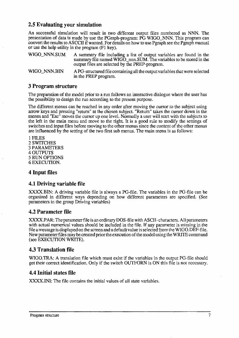
2.5 Evaluating your simulation An successful simulation will result in two different output files numbered as NNN. The presentation of data is made by use the PGraph-program: PG WIGO_NNN. This program can convert the results to ASCCII if wanted. For details on how to use Pgraph see the Pgraph manual or use the help utility in the program (Fl key).
WIGO_NNN.SUM A summary file including a list of output variables are found in the summary file named WIGO_nnn.SUM. The variables to be stored in the output files are selected by the PREP-program.
A PG-structured file containing all the output variables that were selected in the PREP program.
3 Program structure The preparation of the model prior to a run follows an interactive dialogue where the user has the possibility to design the run according to the present purpose.
The different menus can be reached in any order after moving the cursor to the subject using arrow keys and pressing "return" at the chosen subject. "Return" takes the cursor down in the menus and "Esc" moves the cursor up one level. Normally a user will start with the subjects to the left in the main menu and move to the right. It is a good rule to modify the settings of switches and input files before moving to the other menus since the content of the other menus are influenced by the setting of the two first sub menus. The main menu is as follows:
1 FILES 2 SWITCHES 3 PARAMETERS 4 OUTPUTS 5 RUN OPTIONS 6 EXECUTION.
4 Input files
4.1 Driving variable file XXXX.BIN: A driving variable file is always a PG-file. The variables in the PG-file can be organized in different ways depending on how different parameters are specified. (See parameters in the group Driving variables)
4.2 Parameter file XXXX.PAR: The parameter file is an ordinary DOS-file with ASCII- characters. All parameters with actual numerical values should be included in the file. If any parameter is missing in the file a message is displayed on the screen and a default value is selected from the WIGO.DEF-file. New parameter files may be created prior the execution of the model using the WRITE command (see EXEClJTION WRITE).
4.3 Translation file WIGO.TRA: A translation file which must exist if the variables in the output PG-file should get their correct identification. Only if the switch OUTFORN is ON this file is not necessary.
4.4 Initial states file XXXX.INI: The file contains the initial values of all state variables.
Program structure 7
4.5 Final states file
This file contains the final values of all state variables.
4.6 Output file
WIOO_nnn.BIN: PO-structured file with output variables where nnn is the current run number. The file is a binary file to be used by the PGraph program for plotting results from the simulation. The file contains all the outputs selected in the PREP program. In case of having the ADDSIM switch ON you have to specify the name of the output file since the output file will be the same as used by a previous run with the model.
WIOO_nnn.SUM: Contains a summary of all instructions used for the simulation and a summary of simulated results. The first part of this file corresponds with a parameter file. This means that you can always rename or copy this file to a file named for instance MYRUN.PAR which could be used as parameter files for future simulations. If you do not modify the instruction by editing this file or modifying anything by using the PREP program you will reproduce your old run.
4.7 Validation file
A validation file is a file with variables that should be compared with simulated variables. The result of the comparison will be found in the WIOO_NNN.SUM file. The first variable in the validation file will be compared with the first variable in the output PO-file, the second with the second and so wider.
4.8 Other initial files
Here are two other files including initial values Their names are fixed.
WIOO.OIN: The following auxiliary variables should be initialized: OCOHl W= Dry weight of the youngest litter cohort OCOHlN= Nitrogen in the youngest litter cohort OWSL and XWH are not used
WIOO.CIN: If the COMPETITION-swistch is ON the following variables should be initialized: All X-variables (l-OCOX),XNAS, XNA, OCOHlW andOCOHlN (see the section on Output variables)
4.9 General file description
File Description
Files used for the simulation (xxxx are names given by the user):
WIOO.exe Program
WIOO.tra Labels of output variables
xxxx.BIN Input variables (data-file)
xxxx.PAR
xxxx.xIN
WIOO.OIN
WIOO.AUT
8
(the DRIVPORA switch must be ON)
Parameter names and values
Initial values «>0) of state variables (the INSTATE switch must be ON)
Initial values of some auxiliary variables, The name is fixed.
This file has to exist only. Its name is fixed.
Type
ASCII
PORA
ASCII
ASCII
ASCII
ASCII
Input files
WIGO.CIN
WIGO.CUT
Output tiles:
WIGO_nnn.bin
WIGO_nnn.sum
WIGO.sta
WIGO.AUT
WIGO.CIN& WIGO.CUT
xxxx.cmd
WIGO.hlp
Initial values of state and some auxiliary variables. One record for ASCII each plant. Only used if CSTTRE>O. OBS! This file is overwritten during the simulation and has to be updated before each simulation. Its name is fixed.
Has to exist only. Only used if CSTTRE>O. OBS! This file is ASCII overwritten during the simulation. Its name is fixed.
Output variables (data fIle), nnn is number of run. OBS! If the PGRA competition option is used (i.e. CSTTRE>O) the values are means of all plants.
A summary of both inputs and outputs ASCII
Information to WIGO about the current run number. Delete this file if you want to restart from run number 1.
Annual sums of different flow variables ASCII
These files contain the variables originally given in WIGO.CIN. ASCII The values are those of the two last days simulated. Which is the last and which is the next last depends on the number of days simulated. Only used if CSTIRE>O.
Instructions to MR-program about multiple runs with different parameter values. Type: mr xxxx.cmd. (not used)
File containing help information identical to what is written in this paper (not necessary).
This file is created in the following way (by the programmer): (i) >ms WIGO_hlp.doc, make a new section for every symbol name (alt-h for every name and alt-g for the ftrst name of each section), (ii) Retrieve help. set, global settings only (alt-j), (iii) Export ASCII-file (help.txt), unfold the document and write a screen image (alt-k), (iv) DOS> mhelp WIGO.txt (=help.txt).
Files used for running the model and handling output tiles:
plotc.bat Compares two simulations by plotting the variables on the same ASCII graph (e.g. Type: plotc xx 82)
PG-instruction fIle in which the variables that shall be compared ASCII can be chosen.
Files used when making name modifications: For WIGO.P AR-parameters should be given (for programming):
WIGO.DEF: Numbers, Names, Groups and Values PV AL.INC: Numbers PNAME.INC: Names PNAMENOP.INC: Names WIGO.DOC: Names and Description
For X-, T-, G- and D-variables should be given:
Input files 9
PVAL.INC: WIGO.DEF: WIGO.INI: WIGO.TRA: xxxx.BIN: WIGO.GlN: WIGO.AUT: WIGO.CIN: WIGO.DOC:
5 Run options
Numbers Numbers Initial X-values <>0 Names and Description Variables Check Check Check Names, Description and Numbers (D .. )
Are used to specify the timestep, the temporal representation of output variables and the period for the simulation.
5.1 Run no.: You can restart from run number 1 by deleting the file: WIOO.STA
5.2 Start date: The simulation period must be specified with a start and a termination date. The dates will be used when reading the driving variable file and when writing output variables to the PORA-structured result file. The time is fully represented by a string like f.i. 198711031240 but the hour and minutes may be excluded if they are not needed in the simulation.
5.3 Output interval: The output interval determines how frequent the output variables will be given to the output file. The requested output variable can either be a mean value of the whole time interval or, the actual value at the time of output (see the switches, A VERAOEX, .. T, .. 0 and .. D). The output interval is given in units of minutes.
5.4 No of iterations: The time step of the model is one day. No other values are allowed.
5.5 Run id: Any string of characters may be specified as the identification of your simulation in addition to the run number. The identification given will be written in the variable identification field used by the Pgraph-program. Be careful when using long strings of characters since the default information stored in the identification field may be overwritten in some cases.
5.6 Comment:
6 Execute
6.1 Exit The exit command will terminate the interactive session and quit the program without starting a simulation. By creating a parameter file before exit the program the input will be saved.
6.2 Run The run command will terminate the interactive session and start a simulation using the instructions entered. All the instructions are written to the .SUM-file which may be used as a parameter file if you would like to reproduce the simulation.
10 Run options

6.3 Write a parameter file
This will create a new parameter file which includes all the instructions specified. The new parameter file can be used as an input file to the model.
7 Warnings and Errors of parameter values
If you specify your input files or your parameter values in a strange way you may get informations about this before you start executing the model. There are two levels of information: Warnings and Errors.
Normally you will be informed about warning or errors after you have modify a parameter value and moved to the new sub-menu. Some errors are the results of combinations of different parameters values and they may not occur before you try to run the model. In this situation a final check of all input files and all relevant parameter values are made. If the final check results in any warning or error messages you can always return to the PREP program and continue to modify your instructions so they will be within valid ranges of accepted intervals. The list of messages is found in a window under the execute menu.
In case of errors, the model can not run but in case of only warnings you are allowed to run the model.
8 Commands
You start the preparation of a simulation by pressing PREPWIGO on the command line of the DOS system. This will be the starting point for adding any type of new instructions for your simulation. Parameter values from the WIGO.PAR-file will be used if the file is present at the current directory. Otherwise the original (default) values of the model will be used (WIGO.DEF).
You can also start the interactive session with default values taken from another parameter file by entering that parameter file name at the command line: PREP WIGO FILE I will result in default values from the parameter file FILE I.P AR.
You can run the WIGO model in batch mode, which means that you will not make use of the interactive session at all. Instead you will run the model from default values. Type:
PREP -b WIGO FILE I
This will result in a run with the model that use information from the FILE1.PAR file. If information is missing in the FILE I.P AR file values from the original model definition file will be used. A parameter file does not need to be complete. It may be restricted to only instructions that need to be changed compared to what is found in the original model definition file (WIGO.DEF). There are also a possibility to specify a number of parameter files on the command line:
PREP -b WIGO FILE I FILE2 FILE3
This means that the PREP program will first read the instructions of FILE I.P AR then of FILE2.PAR and finally of the FILE3.PAR file. The information read last will be used. But remember that the parameter files not necessarily are complete. They can be organized with only information about for instance harvest in the FILE2.P AR file information about run options like time periods in the FILE3.P AR file.
Wamings and Errors of parameter values
11

9 Problems
If you get problems, find bugs or just want to report an interesting phenomena please let us know about it. Write to:
Henrik Eckersten Department of Soil Science Swedish University of Agricultural Sciences P.O. Box 7014 S-750 07 Uppsala Sweden
Please remember to send a copy of your input data files and the commands used when you get any problems.
10 Help
Help is available (almost) everywhere.
Just press the F1 key and you are transferred to help.
In help, typing a single "RETURN" takes you one level down. By pressing "ESC" you move up again.
The <END> key brings you back to WIOO.
11 References
Papers and reports published with relevance for the WIOO model and publications referred to in the text.
Eckersten, H., 1984b. Light penetration and photosynthesis in a willow stand. In: K.L. Perttu, (Bd.): Ecology and management of forest biomass production systems. Swedish University of Agricultural Sciences, Department of Ecology and environmental Research, Uppsala. Report 15:29-45.
Eckersten, H., 1986a. Simulated willow growth and transpiration: the effect of high and low resolution weather data. Agricultural and Forest Meteorology 38:289- 306.
Eckersten, H., 1986b. Willow growth as a function of climate, water and nitrogen. Department of Ecology & Environmental Research, Swedish University of Agricultural Sciences, Report 25,38 pp.
Eckersten, H., 1991. Growth and nitrogen simulation model for short rotation forests; WlGO - Model description. Division of Agricultural Hydrotechnics, Report 163, Department of Soil Sciences, Swed. Univ. of Agric. Sci., Uppsala. ISRN SLU-HY-R--163--SE. 36pp.
Eckersten, H. & Ericsson, T., 1989. Allocation ofbiomass during growth of willow. In: K.L. Perttu & PJ. Kowalik, (Bds.): Modelling of energy forestry -growth, water relations and economy . Centre for Agricultural publication and documentation (Pudoc), Wageningen, pp. 77-85.
Eckersten, H., Kowalik, P., Nilsson, L.O. & Perttu, K., 1983. Simulation of total willow production. Swedish University of Agricultural Sciences, Section of Energy Forestry, UpPsala. Report 32, 45 pp.
Eckersten, H., Lindroth, A. & Nilsson, L.O., 1987. Willow production related to climatic variations in southern Sweden. Scandinavian Journal of Forest Research 2:99-110.
Eckersten, H., Lindroth, A. & Nilsson, L-O., 1989. Simulated growth of willow stands related to variations in weather and foliage nitrogen content. In: K.L. Perttu & PJ. Kowalik (Bds): Modelling of energy forestry -Growth, Water Relations and Economy. PUDOC, Wageningen, pp. 33-63.
Eckersten H & Slapokas T 1990. Modelling nitrogen turnover and production in an irrigated short-rotation forest. Agr. and For. Meteor. 50:99-123
Nilsson, L.O. & Eckersten, H. 1983. Willow production as a function of radiation and temperature. Agric. Meteorol. 30:49-57.
Perttu, K., Eckersten, H., Kowalik, P. & Nilsson, L.O., 1984. Modelling potential energy forest production. In:
12
Perttu, K. (Bd.). Ecology and management of forest biomass production systems. Dept. Ecol. & Environ. Res., Rep. 15, Swed. Univ. Agric. Sci., Uppsala. 46 pp.
Problems
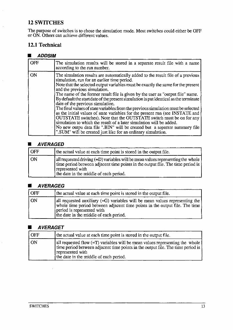
12 SWITCHES
The purpose of switches is to chose the simulation mode. Most switches could either be OFF or ON. Others can achieve different values.
12.1 Technical
• ADDSIM OFF The simulation results will be stored in a separate result file with a name
according to the run number.
ON The simulation results are automatically added to the result file of a previous simulation, run for an earlier time period. Note that the selected output variables must be exactly the same for the present and the previous simulation. The name of the former result file is given by the user as "output file" name. By default the start date of the present simulation is put identical as the terminate date of the previous simulation. The final values of state variables from the previous simulation must be selected as the initial values of state variables for the present run (see INSTATE and OUTSTATE switches). Note that the OUTSTATE switch must be on for any simulation to which the result of a later simulation will be added. No new outpu data file ".BIN" will be created but a separate summary file ".SUM" will be created just like for an ordinary simulation.
• AVERAGED OFF the actual value at each time point is stored in the output file.
ON all requested driving (=D) variables will be mean values representing the whole time period between adjacent time points in the output file. The time period is represented with the date in the middle of each period.
• AVERAGEG OFF the actual value at each time point is stored in the output file.
ON all requested auxiliary (=G) variables will be mean values representing the whole time period between adjacent time points in the output file. The time period is represented with the date in the middle of each period.
• AVERAGET OFF the actual value at each time point is stored in the output file.
ON all requested flow (=T) variables will be mean values representing the whole time period between adjacent time points in the output file. The time period is represented with the date in the middle of each period.
SWITCHES 13
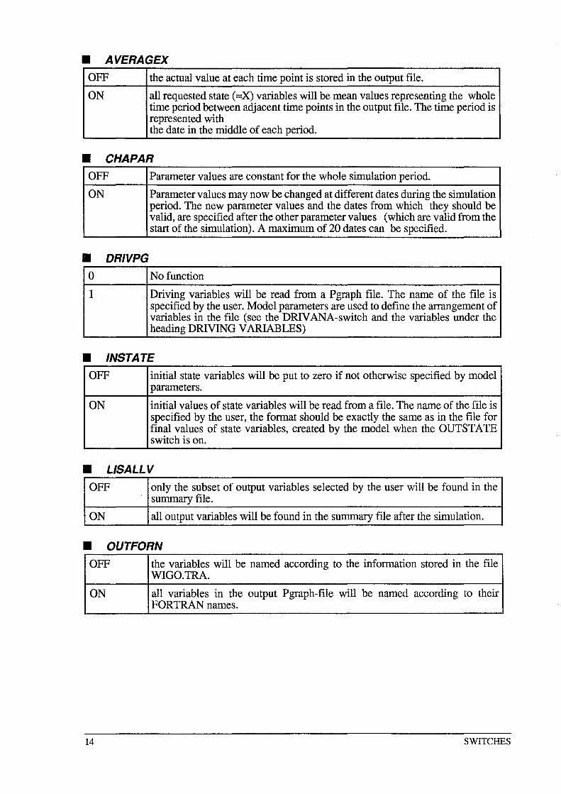
• AVERAGEX OFF the actual value at each time point is stored in the output file.
ON all requested state (=X) variables will be mean values representing the whole time period between adjacent time points in the output file. The time period is represented with the date in the middle of each period.
• CHAPAR OFF Parameter values are constant for the whole simulation period.
ON Parameter values may now be changed at different dates during the simulation period. The new parameter values and the dates from which they should be valid, are specified after the other parameter values (which are valid from the start of the simulation). A maximum of 20 dates can be specified.
• DRIVPG 0 No function
1 Driving variables will be read from a Pgraph file. The name of the file is specified by the user. Model parameters are used to define the arrangement of variables in the file (see the DRIVANA-switch and the variables under the heading DRIVING VARIABLES)
• INSTATE OFF initial state variables will be put to zero if not otherwise specified by model
parameters.
ON initial values of state variables will be read from a file. The name of the file is specified by the user, the format should be exactly the same as in the file for final values of state variables, created by the model when the OUTSTATE switch is on.
• LlSALLV OFF only the subset of output variables selected by the user will be found in the
summary file.
ON all output variables will be found in the summary file after the simulation.
• OUTFORN OFF the variables will be named according to the information stored in the file
WIGO.TRA.
ON all variables in the output Pgraph-file will be named according to their FORTRAN names.
14 SWITCHES
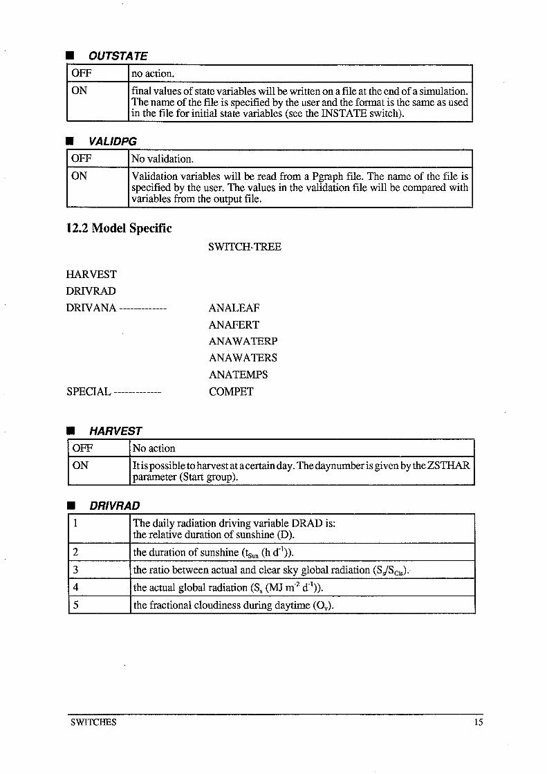
• OUTSTATE OFF no action.
ON final values of state variables will be written on a file at the end of a simulation. The name of the file is specified by the user and the format is the same as used in the file for initial state variables (see the INSTATE switch).
• VALIDPG OFF No validation.
ON Validation variables will be read from a Pgraph file. The name of the file is specified by the user. The values in the validation file will be compared with variables from the output file.
12.2 Model Specific
HARVEST
DRIVRAD
SWITCH-TREE
DRIV ANA ------------- ANALEAF
ANAFERT
ANAWATERP
ANAWATERS
ANATEMPS
COMPET SPECIAL -------------
• HARVEST OFF No action
ON It is possible to harvest at a certain day. The daynumber is given by the ZSTHAR parameter (Start group).
• DRIVRAD 1 The daily radiation driving variable DRAD is:
the relative duration of sunshine (D).
2 the duration of sunshine (!sun (h d-I». 3 the ratio between actual and clear sky global radiation (SjScls).'
4 the actual global radiation (Ss (MJ m-2 d-I». 5 the fractional cloudiness during daytime (Ov).
SWITCHES 15
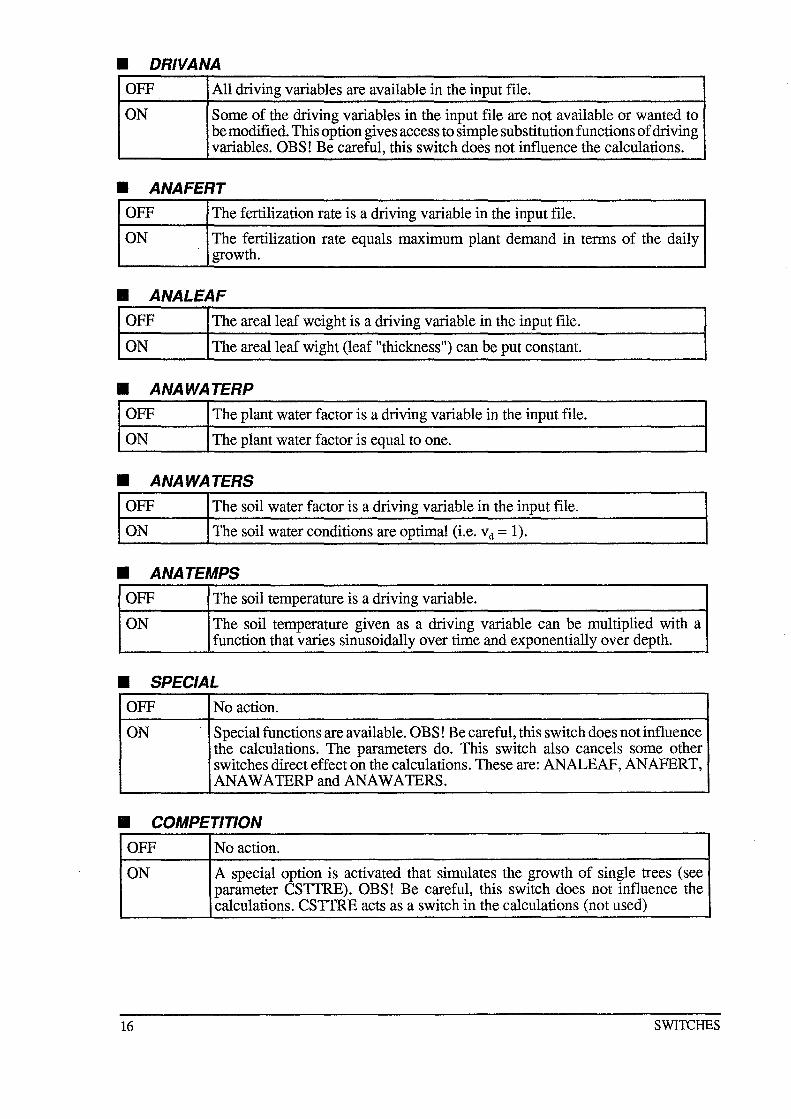
• DRIVANA OFF All driving variables are available in the input file.
ON Some of the driving variables in the input file are not available or wanted to be modified. This option gives access to simple substitution functions of driving variables. OBS! Be careful, this switch does not influence the calculations.
• ANAFERT OFF The fertilization rate is a driving variable in the input file.
ON The fertilization rate equals maximum plant demand in terms of the daily growth.
• ANALEAF OFF The arealleaf weight is a driving variable in the input file.
ON The arealleaf wight (leaf "thickness") can be put constant.
• ANAWATERP OFF The plant water factor is a driving variable in the input file.
ON The plant water factor is equal to one.
• ANAWATERS OFF The soil water factor is a driving variable in the input file.
ON The soil water conditions are optimal (i.e. Vd = 1).
• ANA TEMPS OFF The soil temperature is a driving variable.
ON The soil temperature given as a driving variable can be multiplied with a function that varies sinusoidally over time and exponentially over depth.
• SPECIAL OFF No action.
ON Special functions are available. OBS! Be careful, this switch does not influence the calculations. The parameters do. This switch also cancels some other switches direct effect on the calculations. These are: ANALEAF, ANAFERT, ANA WA TERP and ANAWA TERS.
• COMPETITION OFF No action.
ON A special option is activated that simulates the growth of single trees (see parameter CSTTRE). OBS! Be careful, this switch does not influence the calculations. CSTTRE acts as a switch in the calculations (not used)
16 SWITCHES
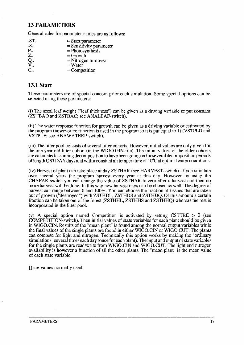
13 PARAMETERS General rules for parameter names are as follows:
.ST.. = Start parameter
.S.. = Sensitivity parameter P.. = Photosynthesis Z.. = Growth Q.. = Nitrogen turnover V.. = Water C.. = Competition
13.1 Start These parameters are of special concern prior each simulation. Some special options can be selected using these parameters:
(i) The arealleaf weight ("leaf thickness") can be given as a driving variable or put constant (ZSTBAD and ZSTBAC; see ANALEAF-switch).
(ii) The water response function for growth can be given as a driving variable or estimated by the program (however no function is used in the program so it is put equal to 1) (VSTPLD and VSTPLE; see ANA W A TERP-switch).
(iii) The litter pool consists of several litter cohorts. However, initial values are only given for the one year old litter cohort (in the WIGO.GIN-file). The initial values of the older cohorts are calculated assuming decomposition to have been going on for several decomposition periods oflength QSTD A Y days and with a constant air temperature of 10°C at optimal water conditions.
(iv) Harvest of plant can take place at day ZSTHAR (see HARVEST-switch). If you simulate over several years the program harvest every year at this day. However by using the CHAP AR -switch you can change the value of ZSTHAR to zero after a harvest and then no more harvest will be done. In this way new harvest days can be chosen as welL The degree of harvest can range between 0 and 100%. You can choose the fraction of tissues that are taken out of growth ("destroyed") with ZSTHDL, ZSTHDS and ZSTHDQ. Of this amount a certain fraction can be taken out of the forest (ZSTHHL, ZSTHHS and ZSTHHQ) whereas the rest is incorporated in the litter pooL
(v) A special option named Competition is activated by setting CSTTRE > 0 (see COMPETITION-switch). Then initial values of state variables for each plant should be given in WIGO.CIN. Results of the "mean plant" is found among the normal output variables while the final values of the single plants are found in either WIGO.CIN or WIGO.CUT. The plants can compete for light and nitrogen. Technically this option works by making the "ordinary simulations" several times each day (once for each plant). The input and output of state variables for the single plants are read/write from WIGO.CIN and WIGO.CUT. The light and nitrogen availability is however a function of all the other plants. The "mean plant" is the mean value of each state variable.
[] are values normally used.
PARAME1ERS 17
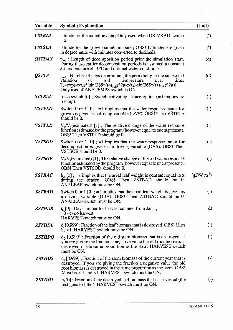
Variable Symbol; Explanation (Unit)
PSTRLA latitude for the radiation data; Only used when DRIVRAD-switch (0) =2.
PSTSLA latitude for the growth simulation site ; OBS! Latitudes are given n in degree units with minutes converted to decimals.
QSTDAY tDee ; Length of decomposition period prior the simulation start. (d) During these earlier decomposition periods is assumed a constant air temperature of lOoC and optimal water conditions.
QSTTS !soil; Number of days determining the periodicity in the sinusoidal (d) variation of soil temperature over time. Ts=exp( -z/Zd) * [sin(365*( t+tsoil)*21t-z/zd)-sin(365*( t+tsoil)*21t)] .
. Only used if ANATEMPS-switch is ON.
STTRAC trace switch [0] ; Switch activating a trace option (=0 implies no (-) tracing)
VSTPLD Switch 0 or 1 [0] ; =1 implies that the water response factor for (-) growth is given as a driving variable (DVP). OBS! Then VSTPLE should be O.
VSTPLE VplVlestimated) [1] ; The relative change of the water response (-) funCTIon estimated by the program (however equal to one at present). OBS! Then VSTPLD should be O.
VSTSOD Switch 0 or 1 [0] ; =1 implies that the water response factor for (-) decomposition is given as a driving variable (DVS). OBS! Then VSTSOE should be O.
VSTSO E V;VS< estimated) [1] ; The relative change of the soil waterresponse ( -) function estimated by the program (however equal to one at present). OBS! Then VSTSOD should be O.
ZSTBAC bA [x] ; =X implies that the arealleaf weight is constant equal to x (gDW m-2)
during the season. OBS! Then ZSTBAD should be O. ANALEAF-switch must be ON.
ZSTBAD Switch 0 or 1 [0] ; =1 implies that the arealleaf weight is given as (-) a driving variable (DBA). OBS! Then ZSTBAC should be O. ANALEAF-switch must be ON.
ZSTHAR 1h [0] ; Day-number for harvest counted from Jan 1; (d) =0 --> no harvest. HARVEST-switch must be ON.
ZSTHDL dl [0.999] ; Fraction of the leafbiomass that is destroyed. OBS! Must (-) . be <1. HARVEST-switch must be ON.
ZSTHDQ do [0.999] ; Fraction of the old stem biomass that is destroyed. If (-) you are giving the fraction a negative value the old root biomass is destroyed in the same proportion as the stem. HARVEST -switch must be ON.
ZSTHDS ds [0.999] ; Fraction of the stem biomass of the current year that is (-) destroyed. If you are giving the fraction a negative value the old root biomass is destroyed in the same proportion as the stem. OBS! Must be >-1 and <1. HARVEST-switch must be ON.
ZSTHHL hi [0] ; Fraction of the destroyed leafbiomass that is harvested (the (-) rest goes to litter). HARVEST-switch must be ON.
18 PARAMETERS
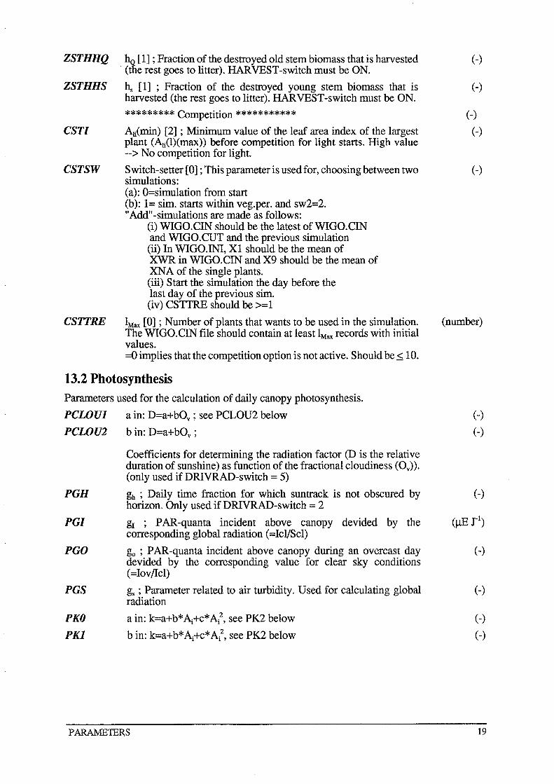
ZSTHHQ hQ [1] ; Fraction of the destroyed old stem biomass that is harvested . (the rest goes to litter). HARVEST-switch must be ON.
ZSTHHS hs [1] ; Fraction of the destroyed young stem biomass that is harvested (the rest goes to litter). HARVEST-switch must be ON.
********* Competition ***********
CSTl Ali(min) [2] ; Minimum value of the leaf area index of the largest plant (Ali(l)(max» before competition for light starts. High value --> No competition for light.
CSTSW Switch-setter [0] ; This parameter is used for, choosing between two simulations: (a): O=simulation from start (b): 1= sim. starts within veg.per. and sw2=2. "Add"-simulations are made as follows:
(i) WIGO.CIN should be the latest ofWIGO.CIN and WIGO.CUT and the previous simulation (ii) In WIGO.INI, Xl should be the mean of XWR in WIGO.CIN and X9 should be the mean of XNA of the single plants. (iii) Start the simulation the day before the last day of the previous sim. (iv) CSTTRE should be >=1
CSTTRE IMax [0] ; Number of plants that wants to be used in the simulation. The WIGO.CIN file should contain at least IMax records with initial values. =0 implies that the competition option is not active. Should be ~ 10.
13.2 Photosynthesis Parameters used for the calculation of daily canopy photosynthesis.
PCWUl a in: D=a+bOv ; see PCLOU2 below
PCWU2 bin: D=a+bOv ;
PGH
PGl
PGO
PGS
PKO
PKl
Coefficients for determining the radiation factor (D is the relative duration of sunshine) as function of the fractional cloudiness (Ov»' (only used ifDRIVRAD-switch = 5)
gh ; Daily time fraction for which suntrack is not obscured by horizon. Only used ifDRIVRAD-switch = 2
gI ; PAR-quanta incident above canopy devided by the corresponding global radiation (=Icl/Scl)
go ; PAR-quanta incident above canopy during an overcast day devided by the corresponding value for clear sky conditions (=IovlIcl)
gs ; Parameter related to air turbidity. Used for calculating global radiation
a in: k=a+b*Aj+c*Aj2, see PK2 below
bin: k=a+b* Aj+c* Aj2, see PK2 below
PARAMETERS
(-)
(-)
(-)
(-)
(-)
(number)
(-)
(-)
(-)
(-)
(-)
(-)
(-)
19
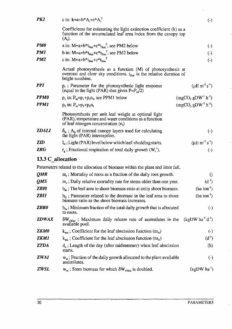
PK2
Coefficients for estimating the light extinction coefficient (k) as a function of the accumulated leaf area index from the canopy top (Ai)'
(-)
PMO a in: M=a+b*tsun+c*tsun2, see PM2 below (-)
PMl b in: M=a+b*tsun+c*ts~, see PM2 below (-)
PM2 c in: M=a+b*tsun+c*tsun2 (-)
Actual photosynthesis as a function (M) of photosynthesis at overcast and clear sky conditions. tsun is the relative duration of bright sunshine.
PPI PI ; Parameter for the photosynthetic light response (J1E m-2 S-l) (equal to the light (PAR) that gives P=P n/2)
PPMO
PPMl
ZDALI
ZID
ZRG
. P1 in: P m=P1+P2nl' see PPMl below
P2 in: P m=P1+P2nl
Photosynthesis per unit leaf weight at optimal light (PAR), temperature and water conditions as a function of leaf nitrogen concentration (nl)
OA; All of internal canopy layers used for calculating the light (PAR) interception.
~ ; Light (PAR) level below which leaf-shedding starts.
rg ; Fractional respiration of total daily growth (W/).
(mgC02 gDW-1 h-1)
(mgC02 gDW-1 h-1)
(-)
13.3 C allocation Parameters related to the allocation of biomass within the plant and litter fall.
QMR II1r ; Mortality of roots as a fraction of the daily root growth. o QMS
ZBIO
ZBIl
ZBRO
ZDWAX
ZKMO
ZKMl
ZTDA
ZWAI
ZWSL
20
Il\ ; Daily relative mortality rate for stems older than one year. (d-1)
bio ; The leaf area to shoot biomass ratio at unity shoot biomass. (ha ton-1)
bit ; Parameter related to the decrease in the leaf area to shoot (ha ton-1) biomass ratio as the shoot biomass increases.
bro ; Minimum fraction of the total daily growth that is allocated (-) to roots.
8WaMax ; Maximum daily release rate of assimilates in the (kgDW ha-1 d-1) available pool.
~o ; Coefficient for the leaf abscission function (mA) (-)
. ~1 ; Coefficient for the leaf abscission function (mA) (d-1)
da ; Length of the day (after midsummer) when leaf abscission (h) starts.
Wai ; Fraction of the daily growth allocated to the plant available (-) assimilates.
Was; Stem biomass for which 8WaMax is doubled. (kgDW ha-1)
PARAMETERS
13.4 N allocation
Parameters related to the allocation of nitrogen within the plant.
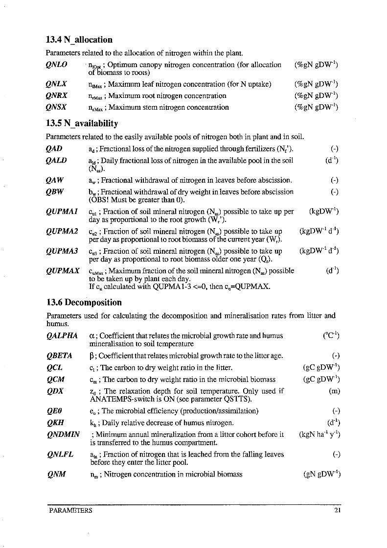
QNLO . nlOpt ; Optimum canopy nitrogen concentration (for allocation of niomass to roots)
QNLX
QNRX
QNSX
nlMax ; Maximum leaf nitrogen concentration (for N uptake)
I1rMax ; Maximum root nitrogen concentration
nsMax ; Maximum stem nitrogen concentration
13.5 N_ availability
(%gN gDW-I)
(%gN gDW-I)
(%gN gDW-I)
(%gN gDW-I)
Parameters related to the easily available pools of nitrogen both in plant and in soil.
QAD ad; Fractional loss of the nitrogen supplied through fertilizers (Nr'). (-)
QAW aid; Daily fractional loss of nitrogen in the available pool in the soil (d-l) (Nas)·
QA W aw ; Fractional withdrawal of nitrogen in leaves before abscission. ( -)
QBW bw ; Fractional withdrawal of dry weight in leaves before abscission (-) (OBS! Must be greater than 0).
QUPMAl CuI; Fraction of soil mineral nitrogen (Nas) possible to take up per (kgDW-I) day as proportional to the root growth (W/).
QUPMA2 cu2 ; Fraction of soil mineral nitrogen (Nas) possible to take up (kgDW-1 dOl) per day as proportional to root biomass of the current year (Wr).
QUPMA3 cu3 ; Fraction of soil mineral nitrogen (Nas) possible to take up (kgDW-1 dOl) per day as proportional to root biomass older one year (Q).
QUPMAX cuMax ; Maximum fraction of the soil mineral nitrogen (Nas) possible (d-l) to be taken up by plant each day. If Cu calculated with QUPMAl-3 <=0, then cu=QUPMAX.
13.6 Decomposition
Parameters used for calculating the decomposition and mineralisation rates from litter and humus.
QALPHA a ; Coefficient that relates the microbial growth rate and humus (0C- l )
mineralisation to soil temperature
QBETA ~ ; Coefficient that relates microbial growth rate to the litter age. (-)
QCL Cl ; The carbon to dry weight ratio in the litter. (gC gDW-I)
QCM Cm ; The carbon to dry weight ratio in the microbial biomass (gC gDW-I)
QDX Zd ; The relaxation depth for soil temperature. Only used if (m) ANA TEMPS-switch is ON (see parameter QSTTS).
QEO eo ; The microbial efficiency (production/assimilation) (-)
QKH kh ; Daily relative decrease of humus nitrogen. (d- l )
QNDMIN ; Minimum annual mineralization from a litter cohort before it (kgN ha-l y-l) is transferred to the humus compartment.
QNLFL aln ; Fraction of nitrogen that is leached from the falling leaves (-) before they enter the litter pool.
QNM llm ; Nitrogen concentration in microbial biomass (gN gDW- I)
PARAMETERS 21

QUO
QWLFL
QZX
uo(1) ; Microbial growth rate ofthe youngest litter cohort (I-year old) at temperature equal to lOoC and at optimal water conditions.
a, ; Fraction of the dry weight in the leaf fall that is leached before entering the litter pool.
z ; Depth of litter cohort. Only used if ANA TEMPS-switch is ON (see parameter QSTIS).
13.7 Temperature _ etc
(-)
(m)
These parameters are related to temperature response, arealleafweight ("leaf thickness") and respiration.
PTl Tl ; Lower temperature limit for growth (see Tf) (OC)
PT2
PT3
ZBAX
ZBAY
ZDAYE
ZDAYTA
ZRM
ZTAACC
T2; Lower temperature limit for optimal growth (see Tf)
T3 ; Upper temperature limit for optimal growth (see Tf)
bAx ; Maximum arealleaf weight
. a in: bA=bAo(1 +a*shootage) ; Annual relative increase of the areal leaf weight (both if it is given as a driving variable or if it is assumed to be constant (see ZSTBAD and ZSTBAC».
le ; Day number at the end of seasonal growth «365)
tAce ; Day number at which the calculation of T aAce starts
rro ; Daily fractional maintain respiration of root and stem biomass of all ages.
T 5 ; Minimum value of the temperature sum (T aAce) at which growth starts.
13.8 Water Parameters related to water response functions for growth and decomposition.
VSOILl av ; see VSOIL4 below
VSOIL2
VSOIL3
VSOlIA
22
bv ; see VSOIL4 below
Cv ; see VSOIL4 below
dv;
av, bv, cv, dv are coefficients for calculating the water reduction factor for decomposition as function of the soil water factor (0 < Vs < 1): Vd = (vs - av)/(bv - av) ; if Vs < Cv Vd = 1 - (vs - cv)!(dv - cv); if Vs > Cv 0< Vd < 1
(OC)
(OC)
(gDWm-2)
(-)
(d DC)
(-)
(-)
(-)
(-)
PARAME1ERS
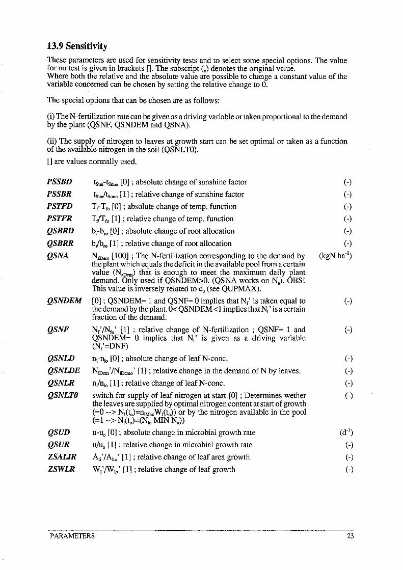
13.9 Sensitivity These parameters are used for sensitivity tests and to select some special options. The value for no test is given in brackets []. The subscript (0) denotes the original value. Where both the relative and the absolute value are possible to change a constant value of the variable concerned can be chosen by setting the relative change to O.
The special options that can be chosen are as follows:
(i) The N-fertilization rate can be given as a driving variable or taken proportional to the demand by the plant (QSNF, QSNDEM and QSNA).
(ii) The supply of nitrogen to leaves at growth start can be set optimal or taken as a function of the available nitrogen in the soil (QSNLTO).
[] are values normally used.
PSSBD tSun-tsuno [0] ; absolute change of sunshine factor (-)
PSSBR tsw/tsuno [1] ; relative change of sunshine factor (-)
PSTFD TrTfo [0] ; absolute change of temp. function (-)
PSTFR T/ffo [1] ; relative change of temp. function (-)
QSBRD br-bro [0] ; absolute change of root allocation (-)
QSBRR bjbro [1] ; relative change of root allocation (-)
QSNA NaDem [100] ; The N-fertilization corresponding to the demand by (kgN ha-I) the plant which equals the deficit in the available pool from a certain value (NaDem) that is enough to meet the maximum daily plant demand. Only used if QSNDEM>O. (QSNA works on Na). OBS! This value is inversely related to Cu (see QUPMAX).
QSNDEM [0] ; QSNDEM= 1 and QSNF= 0 implies that Ne' is taken equal to (-) the demand by the plant. 0< QSNDEM <1 implies thatNf' is a certain fraction of the demand.
QSNF Nf'/Nfo' [1] ; relative change of N-fertilization ; QSNF= 1 and (-) . QSNDEM= 0 implies that Ne' is given as a driving variable (Ne'=DNF)
QSNW nCnlo [0] ; absolute change of leaf N-conc. (-)
QSNWE NJDem'/NIDemo' [1] ; relative change in the demand ofN by leaves. (-)
QSNLR n/nlo [1] ; relative change of leaf N-conc. (-)
QSNLTO switch for supply of leaf nitrogen at start [0] ; Determines wether (-) the leaves are supplied by optimal nitrogen content at start of growth (=0 --> Nl(ta)=nlMax Wl(to)) or by the nitrogen available in the pool (=1 --> Nl(to)=(Nlo MIN Na))
QSUD u-uo [0] ; absolute change in microbial growth rate (d-I)
QSUR u/uo [1] ; relative change in microbial growth rate (-)
ZSALIR All' / Alio' [1] ; relative change of leaf area growth (-)
ZSWLR Wl' /Wlo ' [1] ; relative change of leaf growth (-)
PARAMETERS 23
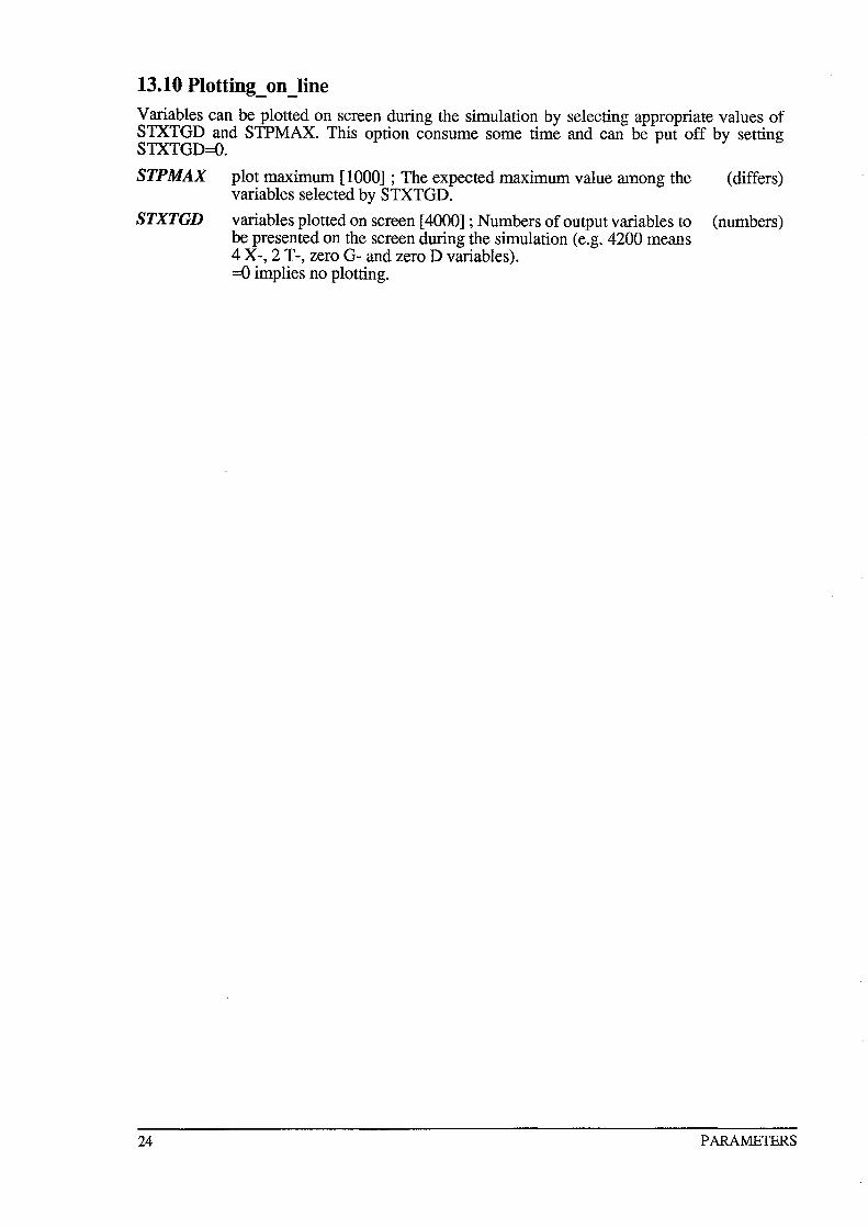
13.10 Plotting_on _line Variables can be plotted on screen during the simulation by selecting appropriate values of STXTGD and STPMAX. This option consume some time and can be put off by setting STXTGD=O.
STPMAX plot maximum [1000] ; The expected maximum value among the (differs) variables selected by STXTGD.
STXTGD variables plotted on screen [4000] ; Numbers of output variables to (numbers) be presented on the screen during the simulation (e.g. 4200 means 4 X-, 2 T-, zero G- and zero D variables). =0 implies no plotting.
24 PARAMETERS
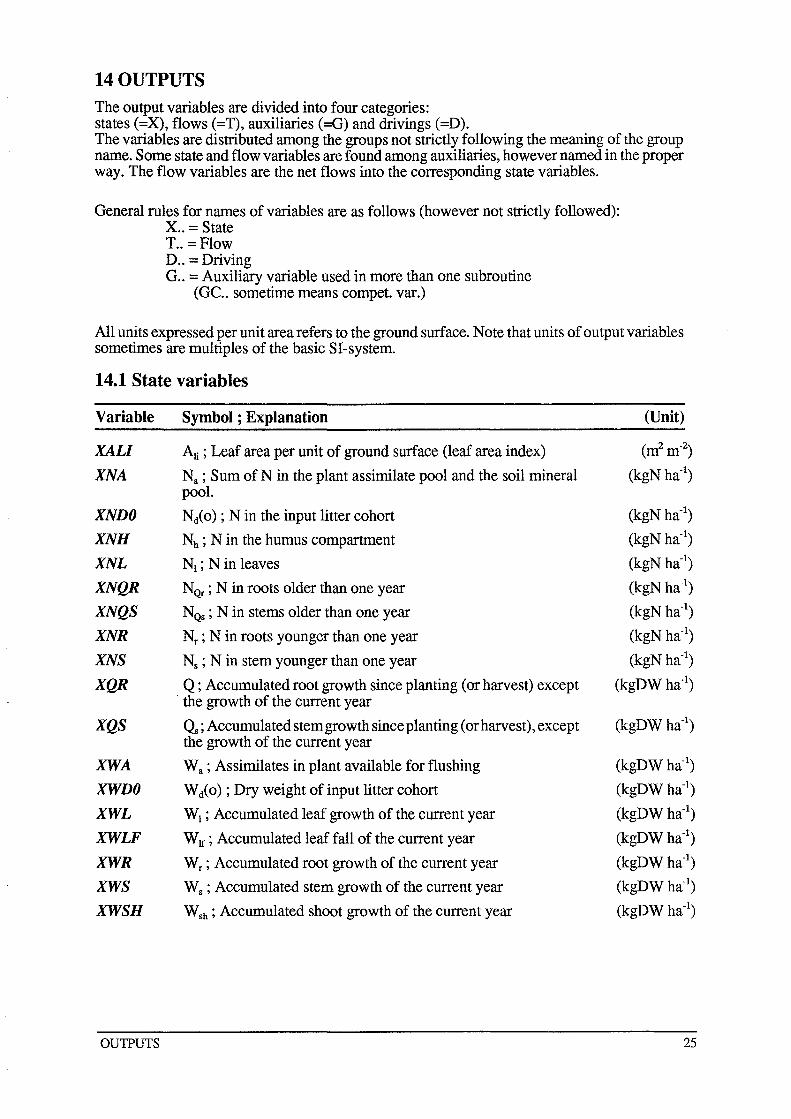
14 OUTPUTS
The output variables are divided into four categories: states (=X), flows (=T), auxiliaries (=G) and drivings (=D). The variables are distributed among the groups not strictly following the meaning of the group name. Some state and flow variables are found among auxiliaries, however named in the proper way. The flow variables are the net flows into the corresponding state variables.
General rules for names of variables are as follows (however not strictly followed): X .. = State T .. = Flow D .. = Driving G .. = Auxiliary variable used in more than one subroutine
(GC .. sometime means compet. var.)
All units expressed per unit area refers to the ground surface. Note that units of output variables sometimes are multiples of the basic SI-system.
14.1 State variables
Variable Symbol; Explanation (Unit)
XALI AJj; Leaf area per unit of ground surface (leaf area index) (nrm-2)
XNA Na ; Sum of N in the plant assimilate pool and the soil mineral (kgN ha-l) pool.
XNDO Ni 0) ; N in the input litter cohort (kgN ha-l)
XNH Nh ; N in the humus compartment (kgN ha-l)
XNL NI ; N in leaves (kgN ha-l)
XNQR NQr ; N in roots older than one year (kgN ha-l)
XNQS NQs ; N in stems older than one year (kgN ha-l)
XNR Nr ; N in roots younger than one year (kgN ha-l)
XNS Ns ; N in stem younger than one year (kgN ha-l)
XQR Q ; Accumulated root growth since planting (or harvest) except (kgDW ha-I) . the growth of the current year
XQS ~ ; Accumulated stem growth since planting (or harvest), except (kgDWha-l) the growth of the current year
XWA Wa; Assimilates in plant available for flushing (kgDWha-l)
XWDO Wi 0) ; Dry weight of input litter cohort (kgDWha-l)
XWL WI ; Accumulated leaf growth of the current year (kgDWha-l)
XWLF W If ; Accumulated leaf fall of the current year (kgDWha-l)
XWR Wr ; Accumulated root growth of the current year (kgDW ha-l)
XWS Ws ; Accumulated stem growth of the current year (kgDWha-l)
XWSH WSh ; Accumulated shoot growth of the current year (kgDWha-l)
OUTPUTS 25
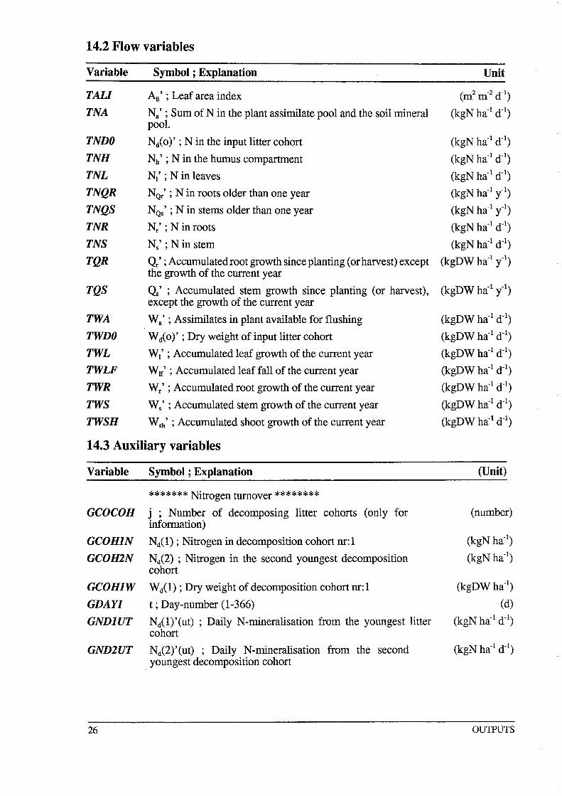
14.2 Flow variables
Variable Symbol; Explanation
TALl An' ; Leaf area index
TNA Na' ; Sum ofN in the plant assimilate pool and the soil mineral pooL
TNDO Ni 0)' ; N in the input litter cohort
TNH Nh' ; N in the humus compartment
TNL NI' ; N in leaves
TNQR NQr' ; N in roots older than one year
TNQS NQs' ; N in stems older than one year
TNR N/ ; N in roots
TNS Ns' ; N in stem
TQR Q.' ; Accumulated root growth since planting (or harvest) except the growth of the current year
TQS Q' ; Accumulated stem growth since planting (or harvest), except the growth of the current year
TWA Wa' ; Assimilates in plant available for flushing
TWDO W i 0)' ; Dry weight of input litter cohort
TWL WI' ; Accumulated leaf growth of the current year
TWLF W If' ; Accumulated leaf fall of the current year
TWR Wr ' ; Accumulated root growth of the current year
TWS Ws' ; Accumulated stem growth of the current year
TWSH Wsh' ; Accumulated shoot growth of the current year
14.3 Auxiliary variables
Variable Symbol; Explanation
******* Nitrogen turnover ******** GCOCOH j; Number of decomposing litter cohorts (only for
information)
GCOHIN Nil); Nitrogen in decomposition cohort nr:l
GCO H2N Ni2); Nitrogen in the second youngest decomposition cohort
GCOHIW Wd(l); Dry weight of decomposition cohort nr:l
GDAYI t ; Day-number (1-366)
GNDIUT Nil)'(ut); Daily N-mineralisation from the youngest litter cohort
GND2UT Ni2)'(ut); Daily N-mineralisation from the second youngest decomposition cohort
26
Unit
(m2 m-2 d-l)
(kgN ha-l d-l)
(kgN ha-l d-l)
(kgN ha-l d-l)
(kgN ha-l d-l)
(kgN ha-l y-l)
(kgN ha-l y-l)
(kgN ha-l d-l)
(kgN ha-l d-l)
(kgDW ha-l il)
(kgDW ha-l il)
(kgDW ha-l d-l)
(kgDW ha- l d-l)
(kgDW ha-l d- l)
(kgDW ha-l d- l )
(kgDW ha- l d-l)
(kgDW ha- l d- l)
(kgDW ha- l d-l)
(Unit)
(number)
(kgN ha-I)
(kgN ha-I)
(kgDWha-l)
(d)
(kgN ha- l d- l)
OU1PUTS
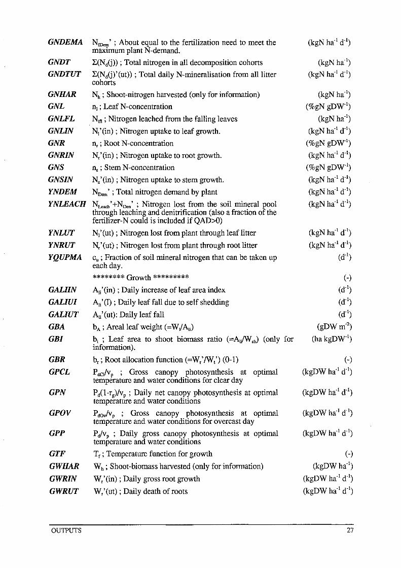
GNDEMA
GNDT
GNDTUT
GNHAR
GNL
GNLFL
GNLIN
GNR
GNRIN
GNS
GNSIN
NtDem ' ; About equal to the fertilization need to meet the maximum plant N-demand.
l.:(Nij» ; Total nitrogen in all decomposition cohorts
l.:(NdG)'(ut» ; Total daily N-mineralisation from all litter cohorts
Nh ; Shoot-nitrogen harvested (only for information)
nJ ; Leaf N-concentration
Nlfl ; Nitrogen leached from the falling leaves
NJ'(in) ; Nitrogen uptake to leaf growth.
I1r ; Root N-concentration
N/ (in) ; Nitrogen uptake to root growth.
ns; Stem N-concentration
Ns' (in) ; Nitrogen uptake to stem growth.
YNDEM NDem' ; Total nitrogen demand by plant
YNLEACH NLeach ' +NDen ' ; Nitrogen lost from the soil mineral pool through leaching and denitrification (also a fraction of the fertilizer-N could is included if QAD>O)
YNLUT
YNRUT
YQUPMA
GALIIN
GALIUI
GALIUT
GBA
GBI
GBR
GPCL
GPN
GPOV
GPP
GTF
GWHAR
GWRIN
GWRUT
OU1PUTS
NJ' (ut) ; Nitrogen lost from plant through leaf litter
N/(ut) ; Nitrogen lost from plant through root litter
Cu ; Fraction of soil mineral nitrogen that can be taken up each day.
******** Growth ********* AJi'(in) ; Daily increase of leaf area index
AJi'(I) ; Daily leaf fall due to self shedding
AJi'(ut): Daily leaf fall
bA ; Arealleafweight (=WJAli)
bi ; Leaf area to shoot biomass ratio (=AJWsJ (only for information).
br ; Root allocation function (=W/IWt') (0-1)
P dclv p ; Gross canopy photosynthesis at optimal temperature and water conditions for clear day
Pil-rg)/vp ; Daily net canopy photosynthesis at optimal temperature and water conditions
PdOV/vp ; Gross canopy photosynthesis at optimal temperature and water conditions for overcast day
PJvp ; Daily gross canopy photosynthesis at optimal temperature and water conditions
Tf ; Temperature function for growth
Wh ; Shoot-biomass harvested (only for information)
W/ (in) ; Daily gross root growth
W/(ut) ; Daily death of roots
(kgN ha-I)
(kgN ha-I d-I)
(kgN ha-I)
(%gN gDW-I)
(kgN ha-I)
(kgN ha-I d-I)
(%gN gDW-I)
(kgN ha-I d-I)
(%gN gDW-I)
(kgN ha-I d-I)
(kgN ha-I d-I)
(kgN ha-I d- I )
(kgN ha- I d- I)
(kgN ha- I d-I )
(d- I)
(-)
(d-I)
(d- I)
(d- I)
(gDWm-2)
(hakgDW- I)
(-)
(kgDW ha- I d-I)
(-)
(kgDWha- l)
(kgDW ha-I d- I)
(kgDW ha- I d- I)
27
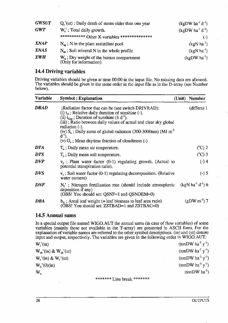
GWSUT
GWT
XNAP XNAS XWH
Cls'(ut) ; Daily death of stems older than one year
W/ ; Total daily growth.
*********** Other X-variables ************** Nap; N in the plant assimilate pool
Nas ; Soil mineral N in the whole profile
Wh ; Dry weight of the humus compartment (Only for information)
14.4 Driving variables
(kgDW ha-l d-l)
(kgDW ha-l d-l)
(-)
(kgN ha-l)
(kgN ha-l)
(kgDWha-l)
Driving variables should be given at time 00:00 in the input file. No missing data are allowed. The variables should be given in the same order in the input file as in the D-array (see Number below).
Variable
DRAD
DTA
DTS
DVP
DVS
DNF
DBA
Symbol; Explanation (Unit) Number
;Radiation factor that can be (see switch DRlVRAD): (i) tn ; Relative daily duration of sunshine (-). (ii) tSun; Duration of sunshine (h d-l). (iii) ; Ratio between daily values of actual and clear sky global radiation (-). (iv) Ss ; Daily sums of global radiation (300-3000nm) (MJ m-2
d- l).
(v) Ov ; Mean daytime fraction of cloudiness (-)
Ta; Daily mean air temperature.
Ts; Daily mean soil temperature.
vp ; Plant water factor (0-1) regulating growth. (Actual to potential transpiration ratio).
vs; Soil water factor (0-1) regulating decomposition. (Relative water content)
Ne' ; Nitrogen fertilization rate (should include atmospheric deposition if any) (OBS! You should set: QSNF=1 and QSNDEM=O)
b A ; Arealleaf weight (= leaf biomass to leaf area ratio) (OBS! You should set: ZSTBAD=1 and ZSTBAC=O)
(differs) 1
(-) 5
14.5 Annual sums
In a special output file named WIGO.AUT the annual sums (in case of flow variables) of some variables (mainly those not available in the T-array) are presented in ASCII form. For the explanation of variable names are referred to the other symbol descriptions. (in) and (ut) denote input and output, respectively. The variables are given in the following order in WIGO.AUT:
Wt'(in) (tonDW ha-l y-l)
Wsh'(in) & Wsh'(ut) (tonDW ha-l il)
W/(in) & W/(ut) (tonDW ha-1 il)
W/(O)(in) (tonDW ha-l il)
Wa (tonDW ha-i)
******* Line break *******
28 OUTPUTS
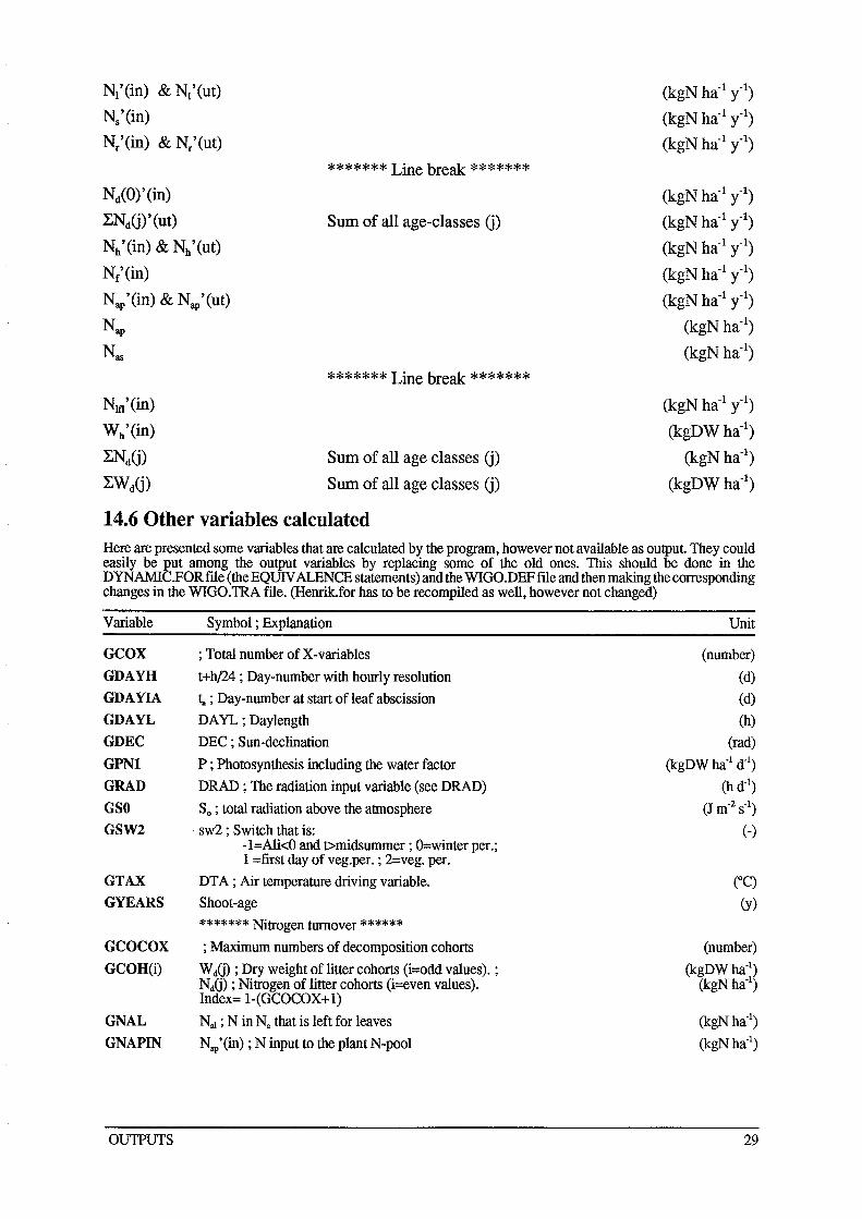
N1'(in) & N1'(ut)
Ns'(in)
N/(in) & N/(ut)
NctCO), (in)
l:NdO), (ut)
Nh'(in) & Nh'(ut)
Nc'(in)
Nap'(in) & N~p'(ut)
Nap
Nas
NIt1 '(in)
Wh'(in)
l:NdO)
l:WdO)
******* Line break *******
Sum of all age-classes 0)
******* Line break *******
Sum of all age classes 0) Sum of all age classes 0)
14.6 Other variables calculated
(kgN ha-l y-l)
(kgN ha-l y-l)
(kgN ha-l y-l)
(kgN ha-l il)
(kgN ha-1 y-l)
(kgN ha-l il)
(kgN ha-l il)
(kgN ha-l il)
(kgN ha-I)
(kgN ha-I)
(kgN ha-l il)
(kgDWha- l)
(kgN ha-I)
(kgDWha- l)
Here are presented some variables that are calculated by the program, however not available as output. They could easily be put among the output variables by replacing some of the old ones. This should be done in the DYNAMIC.FORftle(theEQUIVALENCEstatements)andtheWIGO.DEFftleandthenmakingthecorresponding changes in the WIGO.TRA file. (Henrik.for has to be recompiled as well, however not changed)
Variable Symbol; Explanation Unit
GCOX ; Total number of X-variables (number)
GDAYH t+h/24 ; Day-number with hourly resolution (d) GDAYIA 1.. ; Day-number at start of leaf abscission (d)
GDAYL DA YL ; Daylength (h)
GDEC DEC ; Sun-declination (rad)
GPNl P ; Photosynthesis including the water factor (kgDW ha-1 d-1)
GRAD DRAD ; The radiation input variable (see DRAD) (h d-1)
GSO So ; total radiation above the atmosphere (J m-2 S-I)
GSW2 . sw2 ; Switch that is: (-) -l=AlkO and t>midsummer ; O=winter per.; 1 =first day of veg.per. ; 2=veg. per.
GTAX DT A ; Air temperature driving variable. COC) GYEARS Shoot-age (y)
******* Nitrogen turnover ****** GCOCOX ; Maximum numbers of decomposition cohorts (number) GCOH(i) W dO) ; Dry weight of litter cohorts (i=odd values). ; (kgDWha-1
)
Nij) ; Nitrogen of litter cohorts (i=even values). (kgN ha-I) Index= l-(GCOCOX+l)
GNAL NaJ ; N in N. that is left for leaves (kgNha-1)
GNAPIN Nap'(in) ; N input to the plant N-pool (kgN ha-I)
OUTPUTS 29
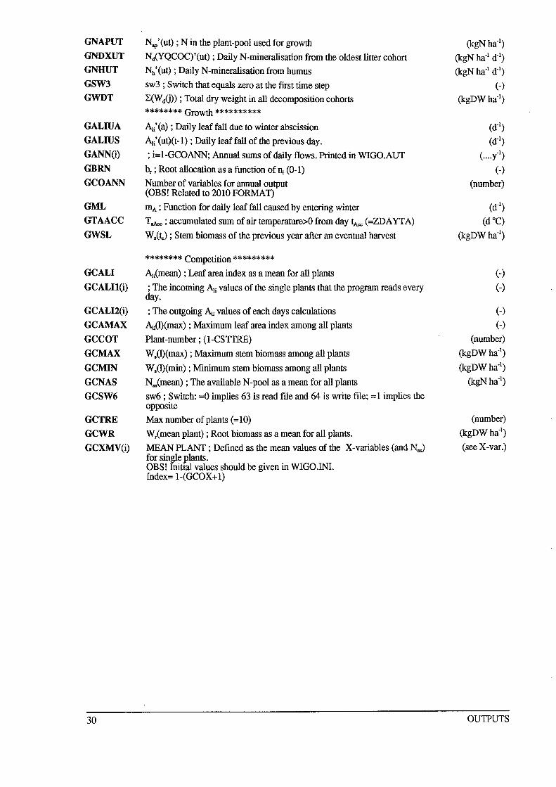
GNAPUT
GNDXUT
GNHUT
GSW3
GWDT
GALIUA
GALIUS
GANN(i)
GBRN
GCOANN
GML
GTAACC
GWSL
GCALI
GCALI1(i)
GCALI2(i)
GCAMAX
GCCOT
GCMAX
GCMIN
GCNAS
GCSW6
GCTRE
GCWR
GCXMV(i)
30
Nap'(ut) ; N in the plant-pool used for growth
NlYQCOC)'(ut) ; Daily N-mineralisation from the oldest litter cohort
Nh'(ut) ; Daily N-mineralisation from humus
sw3 ; Switch that equals zero at the first time step
L<WiD) ; Total dry weight in all decomposition cohorts
******** Growth ********** ~i'(a) ; Daily leaf fall due to winter abscission
Ali'(ut)(t-l); Daily leaf fall of the previous day.
; i=I-GCOANN; Annual sums of daily flows. Printed in WIGO.AUT
br ; Root allocation as a function of nl (0-1)
Number of variables for annual output (OBS! Related to 2010 FORMAT)
mA ; Function for daily leaf fall caused by entering winter
T aAce ; accumulated sum of air temperature>O from day tAce (=ZDA YT A)
W.(~) ; Stem biomass of the previous year after an eventual harvest
******** Competition ********* Ali(mean) ; Leaf area index as a mean for all plants
; The incoming Ali values of the single plants that the program reads every day.
; The outgoing Ali values of each days calculations
Ali(l)(max) ; Maximum leaf area index among all plants
Plant-number; (l-CSTTRE)
W.(l)(max); Maximum stem biomass among all plants
. W.(l)(min) ; Minimum stem biomass among all plants
N .. (mean) ; The available N-pool as a mean for all plants
sw6; Switch: =0 implies 63 is read file and 64 is write file; =1 implies the opposite
Max number of plants (=10)
Wr(mean plant) ; Root biomass as a mean for all plants.
MEAN PLANT; Defined as the mean values of the X-variables (and Nas)
for single plants. OBS! Initial values should be given in WIGO.INI. Index= 1-(GCOX+l)
(kgNha-l) (kgN ha-l dOl)
(kgN ha-l dOl)
(-)
(kgDWha-l)
(d-l )
(d-l )
(. ... y"l)
(-)
(number)
(d-l )
(d QC)
(kgDWha-l)
(-)
(-)
(-)
(-)
(number)
(kgDWha-l)
(kgDWha-l) (kgN ha-I)
(number) (kgDWha-l)
(see X-var.)
OU1PUTS
15 News
Important changes in new versions will be mentioned here.
News 31
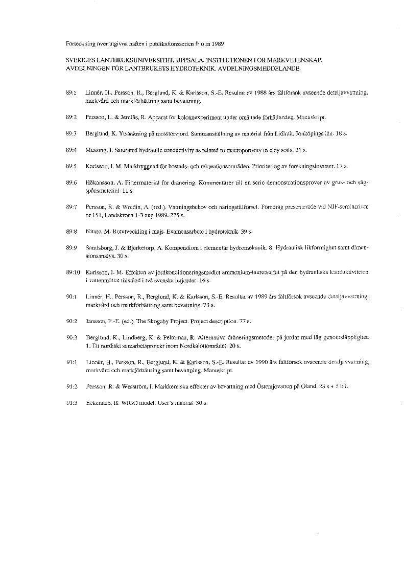
Forteckning over utgivna haften i publikationsserien fr 0 m 1989
SVERIGES LANTBRUKSUNlVERSlTET, UPPSALA. INSTITUTIONEN FOR MARKVETENSKAP.
AVDELNINGEN FOR LANTBRUKETS HYDROTEKNIK. A VDELNINGSMEDDELANDE.
89:1 Linner, H., Persson, R., Berglund, K. & Karlsson, S.-E. Resultat av 1988 ars fiiltfOrsak avseende detaljavvattning, markvard och markforbattring samt bevattning.
89:2 Persson, L. & Jernlas, R. Apparat fOr kolonnexperiment under omattade fOrhallanden. Manuskript.
89:3 Berglund, K. Ytsankning pa mosstorvjord. Sammanstallning av material fran Lidhult, Jonkopings lan. 18 s.
89:4 Messing, 1. Saturated hydraulic conductivity as related to macroporosity in clay soils. 21 s.
89:5 Karlsson, 1. M. Markbyggnad fOr bostads- och rekreationsomraden. Prioritering av forskningsinsatser. 17 s.
89:6 Hakansson, A. Filtermaterial fOr dranering. Kommentarer till en serie demonstrationsprover av grus- och sagspansmaterial. 11 s.
89:7 Persson, R. & Wredin, A. (red.). Vattningsbehov och naringstillfOrsel. Foredrag presenterade yid NJF-scl11inariul11
nr 151, Landskrona 1-3 aug 1989. 275 s.
89:8 Nitare, M. Rotutveckling i majs. Examensarbete i hydroteknik. 39 s.
89:9 Sandsborg, J. & Bjerketorp, A. Kompendium i elementar hydromekanik. 8: Hydraulisk Iikformighet samt dimen
sionsanalys. 30 s.
89:10 Karlsson,1. M. Effekten av jordkonditioneringsmedlet ammonium-Iauretsulfat pa den hydrauliska konduktiviteten i vattenmattat tillstand i tva svenska lerjordar. 16 s.
90:1 Linner, H., Persson, R., Berglund, K. & Karlsson, S.-E. Resultat av 1989 ars faltfOrsak avseende detaljavvattning,
markvard och markf6rbattring sal11t bevattning. 73 s.
90:2 Jansson, P.-E. (ed.). The Skogaby Project. Project description. 77 s.
90:3 Berglund, K., Lindberg, K. & Peltomaa, R. Alternativa draneringsmetoder pa jordar med lag genol11slapplighet.
1. Ett nordiskt samarbetsprojekt inom Nordkalottomradet. 20 s.
91:1 Linner, H., Persson, R., Berglund, K. & Karlsson, S.-E. Resultat av 1990 ars fiiltfOrsak avseende detaljavvattning,
markvard och markfOrbattring samt bevattning. Manuskript.
91:2 Persson, R. & Wesstrom, 1. Markkemiska effekter av bevattning med Ostersjovatten pa Oland. 23 s + 5 bi!.
91:3 Eckersten, H. WIGO model. User's manual. 30 s.