Embed Size (px)
Citation preview
PUBLIC WORKS TECHNICAL BULLETIN 200-1-36 30 SEPTEMBER 2005
SUSTAINABLE STORMWATER STORAGE ALTERNATIVES FOR ARMY INSTALLATIONS

Public Works Technical Bulletins are published by the U.S. Army Corps of Engineers, 441 G Street, NW, Washington, DC 20314-1000. They are intended to provide information on specific topics in areas of Facilities Engineering and Public Works. They are not intended to establish new DA policy.

DEPARTMENT OF THE ARMY U.S. Army Corps of Engineers
441 G Street, NW Washington, DC 20314-1000
CEMP-CE
Public Works Technical Bulletin 30 September 2005 No. 200-1-36
Facilities Engineering Environmental
SUSTAINABLE STORMWATER STORAGE ALTERNATIVES FOR ARMY INSTALLATIONS
1. Purpose. This Public Works Technical Bulletin (PWTB) transmits current information on a variety of alternative methods to store stormwater and applicability of these methods to Army installations. The Assistant Chief of Staff for Installation Management requires that, in order to meet the “Gold” rating level, a rating tool called SPiRiT be used for all new construction on Army installations. SPiRiT (see http://www.cecer.army.mil/SustDesign/SPiRit.cfm or https://eko.usace.army.mil/fa/sdd/) was developed for the Army based on the concepts of Leadership in Energy and Engineering Design (LEED), which is a rating tool developed by the U.S. Green Building Council to encourage sustainable development. The Army is transitioning to the use of LEED guidelines in the near future (expected first quarter FY06). LEED and SPiRiT goals are not applicable to Civil Works projects at this time. Army regulations and policy addressing water quantity from development sites include 40 CFR 122.26, the Clean Water Act, and Army Regulation (AR) 200-1. Sustainable stormwater management is also required under Executive Order 13123, Greening the Government through Efficient Energy Management.
2. Applicability. This PWTB applies to all U.S. Army facility engineering activities within the United States.

PWTB 200-1-36 30 September 2005
2
3. References.
a. AR 200-1, “Environmental Protection and Enhancement,” 21 February 1997.
b. Appendix E lists additional references.
4. Discussion.
a. The Army is pursuing sustainable installations and low impact development (LID) in many applications. In the area of stormwater storage, a large number of alternatives have recently emerged from private sector vendors claiming to cost-effectively store stormwater for beneficial reuse. These alternatives are being installed without any demonstrated performance data, in some cases, and can often be expensive compared with traditional storage and reuse options. Currently, no Army-specific guidance is available that addresses use of these alternatives.
b. Sustainable stormwater storage should be considered in the context of the LID approach to stormwater management, which follows the basic principles of nature: manage rainfall as near the source as possible using micro-scale controls. LID’s goal is to mimic a site’s predevelopment hydrology by using design techniques that infiltrate, filter, store, evaporate, and detain runoff close to its source. Techniques are based on the premise that stormwater management should not be seen as stormwater disposal. Instead of conveying and managing/treating stormwater in facilities at the bottom of drainage areas, LID addresses stormwater through small, cost-effective features at lot or local level. LID can save money over conventional approaches by reduced infrastructure and site preparation work (up to 25 to 30 percent) through reductions in clearing, grading, pipes, ponds, inlets, curbs, and paving, and through potential space recovery for other positive uses.
c. This report summarizes the variety of storage alter-natives available other than traditional detention ponds. The focus is on alternatives for smaller sites, addressing plastic, metal, and concrete-type structures with an emphasis on underground storage so that surface areas may be used for other purposes. Alternatives discussed include pipe networks of various materials (corrugated steel, plastic and concrete); interlocking plastic block structures; French drains; and concrete vaults.
d. Appendix A: Stormwater Management Methods reviews LID and other potential options for beneficial use of a valuable


PWTB 200-1-36 30 September 2005
CONVERSION FACTORS
Quantity To convert from customary unit To metric unit
Multiply customary unit
by
To convert to customary unit, multiply metric unit
by Length inches (in.)
inches (in.) feet (ft)
millimeters (mm)a
centimeters (cm) meters (m)
25.44 2.54
0.304
0.03937 0.3937 3.2808
Area square inches (in2)
square feet (ft2) acres (ac)
square millimeter (mm2) square meters (m2) hectares (ha)
645.16 0.092903 0.40469
0.00155 10.764 2.4710
Volume gallons (gal)
cubic feet (ft3) cubic yards (yd3) acre-feet (ac-ft) acre-feet (ac-ft)
liters (L) cubic meters (m3) cubic meters (m3) thousand cubic meters (m3) hectare-meters (ha-m) 2
3.7854 0.028317 0.76455 1.2335 0.1234
0.26417 35.315 1.308
0.8107 8.107
Flow cubic feet per second
(ft3/s) gallons per minute (gal/min)
cubic meters per second (m3/s) liters per minute (L/min)
0.028317
3.7854
35.315
0.26417
Mass pounds (lb) tons short, 2,000 lb
kilograms (kg) megagrams (Mg)
0.45359 0.90718
2.2046 1.1023
Pressure pounds per square inch
(psi)
kilopascals (kPa) 6.8948
0.14505
a When using “dual units,” inches are normally converted to millimeters (rather than centimeters). b Not used often in metric countries, but is offered as a conceptual equivalent of customary western U.S. practice (a standard
depth of water over a given area of land).
OTHER COMMON CONVERSION FACTORS 1 cubic foot=7.48 gallons=62.4 pounds of water 1 cubic foot per second (cfs)=450 gallons per minute (gpm) 1 cfs=646,320 gallons a day=1.98 ac-ft a day 1 acre-foot=325,900 gallons =43,560 cubic feet 1 million gallons=3.07 acre-feet 1 million gallons a day (mgd)=1,120 ac-ft a year

PWTB 200-1-36 30 September 2005
A-1
APPENDIX A
STORMWATER MANAGEMENT METHODS
Stormwater should be considered a potential resource for process use, dust suppression, recharge of the water table aquifer, and seasonal storage to supplement irrigation supplies. The following sections include some alternative methods for stormwater storage.
Low-Impact Development (LID) in Stormwater Management
Sustainable stormwater storage should also be considered in the context of Low Impact Development (LID). The LID approach to stormwater management follows the basic principles of nature: manage rainfall as near the source as possible using micro-scale controls. LID’s goal is to mimic a site’s predevelopment hydrology by using design techniques that infiltrate, filter, store, evaporate, and detain runoff close to its source. Techniques are based on the premise that stormwater management should not be seen as stormwater disposal. Instead of conveying and managing/treating stormwater in facilities at the bottom of drainage areas, LID addresses stormwater through small, cost-effective features at lot or local level. Components include open space, rooftops, streetscapes, parking lots, sidewalks, and medians. LID is applicable for new construction and retrofit and revitalization projects. LID can save money over conventional approaches by reduced infrastructure and site preparation work (up to 25 to 30 percent) through reductions in clearing, grading, pipes, ponds, inlets, curbs, and paving, and through potential space recovery for other positive uses.
Additional information is available at a website funded by the USEPA: http://www.lid-stormwater.net. A literature review is available from the USEPA at www.epa.gov/owow/nps.lid/lid.pdf.
An excellent overview of LID has been published by the Puget Sound Action Team and is on-line at: http:/www.psat.wa.gov/Publications/LID_tech_manual05/lid_index.
A Unified Facilities Design manual UFC 3-210-10 for LID on military installations is available at: http://www.wbdg.org/references/ccbdoc.

PWTB 200-1-36 30 September 2005
A-2
The five basic steps in a LID design are conservation, minimization, runoff concentration, distributed integrated management, and pollution prevention:
Conservation measures
LID encourages conservation of forests, natural vegetation, streams, wetlands, and open space. These features should be multifunctional (Figure A1).
Figure A1. Multifunctional use of green space.
(Used with permission.)
http://www.werf.org/press/winter01/01w_low.cfm
Minimization techniques
These techniques reduce hydrologic impacts or maintain hydrologic functions (for example, reduced clearing and grading, saving infiltrable soils, and limiting lot disturbance).
Concentration of runoff
Use open drainage systems, flatter slopes, dispersed drainage, longer and/or natural flow paths, vegetative swales, and maximized sheet flow to slow down runoff. Slower runoff reduces discharges and encourages more infiltration and evaporation.
Use of distributed integrated management practices
These practices include individual techniques integrated into the site to provide retention, detention, filtration, and storage of runoff for various uses. Techniques include bioretention (rain gardens), depression storage, infiltration practices, rooftop storage, pipe storage, street and parking lot storage, rainwater use, compact weir outfalls to dissipate

PWTB 200-1-36 30 September 2005
A-3
stormwater energy and improve water quality, and soil amendments to increase storage.
Effective use of pollution prevention
Reducing pollutants introduced to the environment helps improve water quality.
Bioretention or “Rain Gardens”
Development of bioretention (a plant soil filter technique) or “rain gardens” (using the green space to manage runoff within small, depressed, upland landscaped areas) has led to understanding how small-scale techniques can be integrated with developed landscapes. A rain garden is a depressional area constructed with layers of soils with high infiltration rates and vegetation designed to intercept stormwater. Infiltration reduces pollutant load by adsorption to soil particles, plant uptake, microbial processes, and sedimentation.
To prevent groundwater contamination, the bed must be lined with geotextile fabric or with sand or gravel base, depending on existing soil conditions (Figure A2). The vegetation filters and transpires runoff, and the root systems enhance infiltration. Bioretention areas can be incorporated into large development sites (parking islands and/or perimeter areas) or on a small scale in residential lawns.
Figure A2. Recharge garden/bioretention bed conceptual detail.
(Used with permission.)
http://www.thcahill.com/recharge.html
PWTB 200-1-36 30 September 2005
A-4
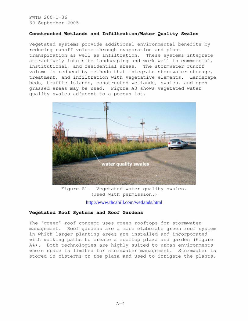
Constructed Wetlands and Infiltration/Water Quality Swales
Vegetated systems provide additional environmental benefits by reducing runoff volume through evaporation and plant transpiration as well as infiltration. These systems integrate attractively into site landscaping and work well in commercial, institutional, and residential areas. The stormwater runoff volume is reduced by methods that integrate stormwater storage, treatment, and infiltration with vegetative elements. Landscape beds, traffic islands, constructed wetlands, swales, and open grassed areas may be used. Figure A3 shows vegetated water quality swales adjacent to a porous lot.
Figure A1. Vegetated water quality swales.
(Used with permission.)
http://www.thcahill.com/wetlands.html
Vegetated Roof Systems and Roof Gardens
The “green” roof concept uses green rooftops for stormwater management. Roof gardens are a more elaborate green roof system in which larger planting areas are installed and incorporated with walking paths to create a rooftop plaza and garden (Figure A4). Both technologies are highly suited to urban environments where space is limited for stormwater management. Stormwater is stored in cisterns on the plaza and used to irrigate the plants.

PWTB 200-1-36 30 September 2005
A-5
Figure A4. Vegetated rooftops in Stuttgart, Germany.
(Used with permission.)
http://www.thcahill.com/roof.html
Subsurface Infiltration Bed Based on the Use of Porous Asphalt
This stormwater management system is based on the use of porous asphalt. Porous asphalt pavement consists of standard bituminous asphalt, which contains aggregate fines (particles less 600μ, or the No. 30 sieve). The fines are screened and reduced to allow water to pass through the asphalt.
A bed of uniformly graded, cleaned-washed stone aggregate with void space of 40 percent is placed under the pavement. The stormwater drains through the asphalt and is held in the stone bed before slowly infiltrating into the underlying soil mantle. Geotextile filter fabric separates the stone bed from the underlying soil, preventing the movement of fines into the bed. The stone bed is usually between 18 and 36 inches deep, depending on stormwater storage requirements, frost depth, and site grading. Porous pavement is suited for parking lots and stormwater management systems. The underlying stone bed can also provide stormwater management for adjacent impervious areas such as roofs and roads. In these cases, the stormwater is sent directly into the stone bed and perforated pipes are used to evenly distribute the water throughout the infiltration bed.
PWTB 200-1-36 30 September 2005
A-6
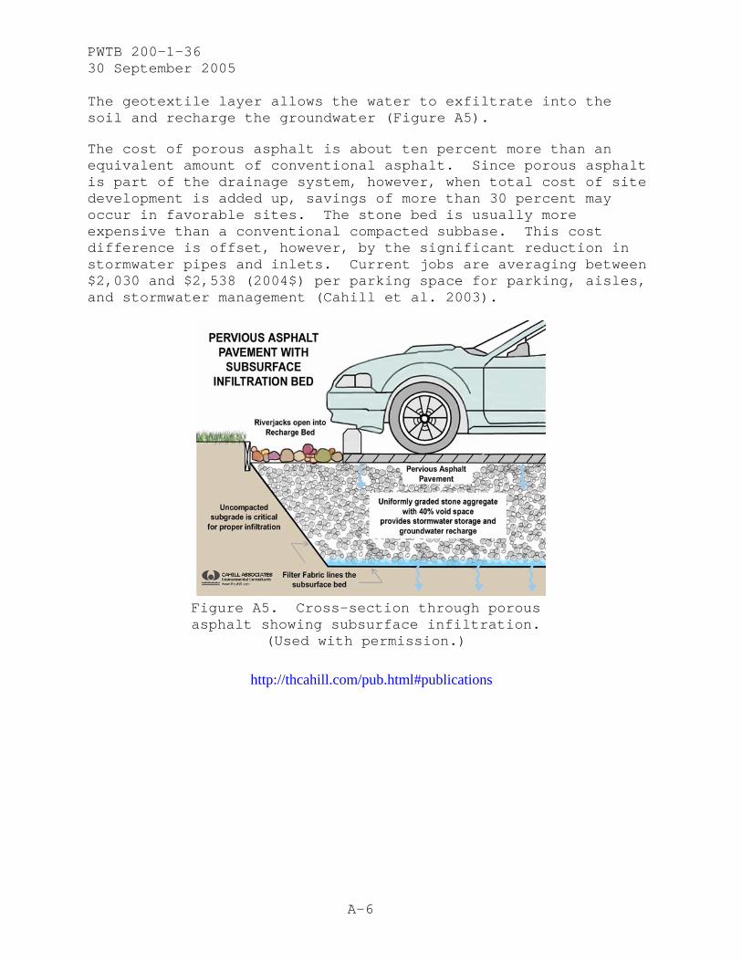
The geotextile layer allows the water to exfiltrate into the soil and recharge the groundwater (Figure A5).
The cost of porous asphalt is about ten percent more than an equivalent amount of conventional asphalt. Since porous asphalt is part of the drainage system, however, when total cost of site development is added up, savings of more than 30 percent may occur in favorable sites. The stone bed is usually more expensive than a conventional compacted subbase. This cost difference is offset, however, by the significant reduction in stormwater pipes and inlets. Current jobs are averaging between $2,030 and $2,538 (2004$) per parking space for parking, aisles, and stormwater management (Cahill et al. 2003).
Figure A5. Cross-section through porous asphalt showing subsurface infiltration.
(Used with permission.)
http://thcahill.com/pub.html#publications
PWTB 200-1-36 30 September 2005
A-7
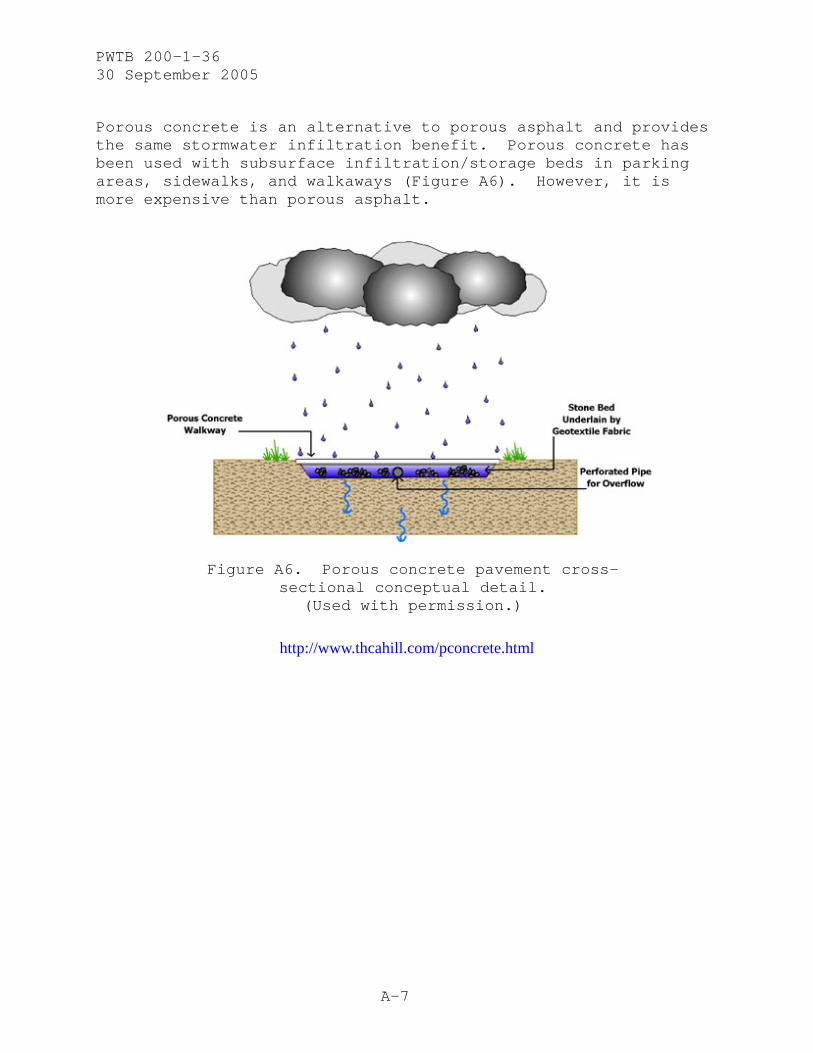
Porous concrete is an alternative to porous asphalt and provides the same stormwater infiltration benefit. Porous concrete has been used with subsurface infiltration/storage beds in parking areas, sidewalks, and walkaways (Figure A6). However, it is more expensive than porous asphalt.
Figure A6. Porous concrete pavement cross-
sectional conceptual detail. (Used with permission.)
http://www.thcahill.com/pconcrete.html

PWTB 200-1-36 30 September 2005
A-8
Subsurface Infiltration Bed Under Soil or Vegetated Cover
A stone storage infiltration bed can be placed under a soil or vegetated cover. This placement will maintain the natural hydrologic cycle and stormwater will be infiltrated into the aquifer. This method is suitable for large athletic fields and play areas, and the stormwater can be reused for irrigation. Roof leaders (downspouts) can also convey building runoff directly to the bed under the field. See Figure A7.
Figure A7. Subsurface infiltration bed under soil or vegetation
(conceptual cross-section detail). (Used with permission.)
http://www.thcahill.com/
Subsurface Infiltration Trench
Detention basins as primary methods of stormwater management have failed to keep pace with fast growing urban areas. One way to control stormwater volume and quality is to retrofit detention basins. One such project installed a 364-foot infiltration trench (Figures A8 and A9) within the basin to intercept the flow from existing stormwater conveyance pipes. The infiltration trench reduces the runoff volume and nonpoint source pollutants previously discharged from the basin. Infiltration trenches may have a variety of surface covers such as pervious or traditional asphalt, concrete, paver blocks, soil with vegetation, aggregate, and sand. (Note: Soil percolation testing is critical before any retrofit solution can be recommended.)

PWTB 200-1-36 30 September 2005
A-9
Figure A8. Construction of infiltration trench.
(Used with permission.)
http://www.thcahill.com/
Figure A9. Infiltration trench installation conceptual detail. (Used with permission.)
http://www.thcahill.com/
PWTB 200-1-36 30 September 2005
A-10
Pipe Detention and Retention Systems
Reinforced concrete pipe (RCP) is fuel- and fire-resistant and takes heavy loads, which makes it useful under taxiways and parking garages. It can be used where pipe depth is shallow and can also handle burials of 100 feet or more without deflecting or collapsing. It is manufactured in 12- to 120-inch round and 18- to 108-inch elliptical RCP.
Plastic pipe comes as polyvinyl chloride (PVC) or high-density polyethylene (HDPE). Its flexibility is an advantage. PVC pipe has a higher tensile strength and a greater stiffness compared with other thermal plastics. It is the most prevalent material for stormwater transmission.
Aluminum pipe and other types of corrugated metal pipe with metallic and nonmetallic coating offer alternatives. The coatings help extend service life and allow these pipes to be used in a wide environmental range.
http://www.forester.net/sw_0209_helping.html
The storage capacity of a corrugated steel pipe (CSP) detention system is virtually unlimited. Space permitting, any number of chambers can be added for an increased capacity. A simple system may consist of a single chamber with welded end caps, inlet, outlet, and means of access to the chamber. Single detention chambers, scattered throughout the site, can often use existing natural drainage and may eliminate the need to convey water to a large central multibarrel structure. Small-diameter CSP can be used to connect multiple barrels or convey system discharges. Most underground detention systems are designed and installed with minimal cover, typically 4 feet or less. Simple, more economical, 30-inch access risers can be substituted for larger, more expensive, storm drain sized manholes with prefabricated ladder assemblies (Figure A10).

PWTB 200-1-36 30 September 2005
A-11
Figure A10. Corrugated steel pipe detention system. (Used with permission.)
http://www.pcpipe.com
Retention systems are essentially the same as detention systems except that the water is retained for some beneficial purpose, commonly groundwater recharge, irrigation, and process water for industry. As more impervious surfaces are constructed, more rainfall is carried off via surface drainage systems and less is available to percolate back into the earth to replenish groundwater supplies. Where soil surrounding the pipe is sufficiently permeable, recharge can be accomplished by slotting or perforating the pipe to allow water to seep into the ground. In less permeable soils, areas of soil exposure can be used to convey water to the desired aquifer. In most cases, perforated metal pipe, with optional ballast rock, wrapped in filter fabric is the most efficient and cost-effective method of redirecting stormwater runoff to groundwater recharge. Table A1 includes dimensions and capacities of CSP.

PWTB 200-1-36 30 September 2005
A-12
Table A1. Properties of corrugated steel pipe.
Corrugated Steel Pipe Detention Chamber
Diameter Volume / LF (Inch) Cubic Ft gallons
Weight (lb/ft)
Minimum Gauge
CORR (Inch
Larger sizes available 96 50.3 376 87 16 3x1 90 44.2 331 82 16 3x1 84 38.5 288 77 16 3x1 78 33.2 248 71 16 3x1 72 28.3 212 66 16 3x1 66 23.8 178 60 16 3x1 60 19.6 147 55 16 3x1
Smaller sizes available Source: Pacific Corrugated Pipe Company
Underground stormwater detention systems capture and store surface run-off and release the water through specifically sized outlet pipes (Figure A11). They are usually installed under streets, parking lots, and parks. The recharge retention method of stormwater control is frequently a viable addition to detention facilities. In sites where soils drain well and the water table is low enough to accommodate a recharge system, such water management techniques may be the most economical means of managing runoff. Pipe-arch with its normally nontight bands naturally provides some degree of recharge. In fine backfills, the joints should be wrapped with a geotextile.
Figure A11. Installing corrugated metal pipes.
http://www.contech-cpi.com/products/applications.asp?id=10

PWTB 200-1-36 30 September 2005
A-13
French Drains
A French drain includes a land drain installed at the bottom of a trench that has been backfilled with shingle or other coarse stone (Figure A12). The sides of the drain may be lined with a geotextile filter membrane that will prevent the transmission of fines from the surrounding into the French drain. The land drain may also be wrapped in the membrane. The purpose of this drain is to alter the pattern of the drainage in a certain area. These drains may be used in fields and other open spaces or close to buildings.
http://www.ihbc.org.uk/Technical%20Papers/French%20Drains.htm
Figure A12. French drain.
http://www.georgiastormwater.com/vol2/3-2-5.pdf

PWTB 200-1-36 30 September 2005
A-14
Underground Detention Vaults and Tanks
Detention vaults are box-shaped underground stormwater storage facilities usually constructed of reinforced concrete. Figure A13 is a schematic of an underground detention vault. Detention tanks are underground storage facilities constructed of large diameter metal or plastic pipe (Figure A14). Both of these facilities serve as an alternative to surface dry detention for stormwater quality control. The water that is captured in the vaults or tanks may be used to irrigate parkstrips, common areas, and general landscaping activities.
Figure A13. Schematic of typical underground detention vault.

PWTB 200-1-36 30 September 2005
A-15
Figure A14. Example of an underground detention tank system.
http://www.georgiastormwater.com/vol2/3-4-3.pdf
Geosynthetics in Stormwater Management
Geosynthetic materials reduce or eliminate soil erosion and chemical leaching that would otherwise degrade surface waters or underground reservoirs. The geosynthetics family includes seven subgroups (Woolson 2003):
Geotextiles
This subgroup consists of synthetic fibers and ensures that biodegradation is not a problem. The fabric always performs at least one of five discrete functions: separation, reinforcement, filtration, drainage, or barrier to moisture. Typical cost of installed Geotextile ranges from $0.71 to $0.92 per yd2 (2004$).
http://www.geotextile.com/case/pdf/case5.pdf
Geomembranes
Geomembranes are impervious thin sheets of rubber or plastic material used primarily for linings and covers of liquid- or

PWTB 200-1-36 30 September 2005
A-16
solid-storage facilities. The primary function is always as a liquid or vapor barrier.
Geogrids
Geogrids are plastics formed into very open, gridlike configurations. They function almost exclusively for soil reinforcement in earth works, road construction, segmented wall constructions, landfill, and hydraulic engineering. A cost comparison of a commercial geogrid product (Secugrid®) and a conventional method is shown in Table A2. The project involved the construction of a site access road total length 1,000 meters and width 9.50 meters. Using the geogrid method, savings were about $100,000 compared with the conventional method.
Table A2. Cost comparison of conventional solution and geogrid solution.
Description Solution 1 Conventional
(2004$)
Solution 2 Geogrid Solution (Secugrid®)
(2004$) Wages $90,820.50 $80,798.00 Equipment $61,501.60 $50,986.40 Material $380,373.00 $345,481.00 Subcontractor $103,969.00 $69,412.80 General site equipment $4,112.44 $4,076.91 Salary and other site costs $54,683.50 $48,433.90 General costs $61,817.80 $53,228.90 Risk and profit $15,454.70 $13,307.80 Total Net $772,734.00 $665,355.00 VAT $123,638.00 $106,457.00 Total Gross $896,942.00 $771,812.00
http://www.geosynthetica.net/news/NaueCostCompare.pdf
Geonets (geospacers)
Geonets are usually formed by a continuous extrusion of parallel sets of polymeric ribs at acute angles to one another. When the ribs are opened, relatively large apertures are formed into a netlike configuration. Their design function is completely within the drainage area, where they have been used to convey fluids of all types.
Geosynthetic clay liners
Rolls of thinly layered bentonite clay are sandwiched between two geotextiles or bonded to a geomembrane. These products are being used as a composite component beneath a geomembrane or by themselves as primary or secondary liners.

PWTB 200-1-36 30 September 2005
A-17
Geopipe
Perhaps the original geosynthetic material still available today is buried plastic pipe. Its function is clearly drainage.
Geocomposites
Combinations of geotextile and geogrid; geogrid and geomembrane; geotextile, geogrid, and geomembrane; or any one of these three materials with another material (e.g., deformed plastic sheets, steel cables, or steel anchors) are geocomposites. They encompass the entire range of functions for geosynthetics: separation, reinforcement, filtration, drainage, and liquid barrier.
“Geo-others”
"Geo-others" include such products as threaded soil masses, polymeric anchors, and encapsulated soil cells. Its primary function is product-dependent and can be any of the five major functions of geosynthetics.
Cost Estimates
Geomembranes - $11.98/yd2
Geotextiles - $1.33/yd2
Geocomposites - $2.66/yd2
Geonets - $2.66/yd2
Geogrids - $6.66/yd2
http://www.ce.berkeley.edu/~pestana/ce176/5-show.pdf
Geosynthetics as Turf Reinforcement Mats (TRMs)
A stormwater channel project in Loudoun County, VA, using a high-performance TRM (defined by the Environmental Protection Agency [EPA] as a combination of high-end hydraulic performance characteristics and 3,000-lb tensile strength) prevented soil erosion and provided stormwater runoff filtration and infiltration. The 1-inch thick mats replaced 2 feet of riprap. The installation of 2 feet of rock would have required 2 feet of sediment to be removed from the channel. One roll of TRM can eliminate seven dump trucks driving onto the site to remove the dirt and five trucks to haul in the rocks (Figure A15).

PWTB 200-1-36 30 September 2005
A-18
Figure A15. The required amount of excavation is reduced using a TRM. (Reprinted by permission of Stormwater Magazine, www.StormH2o.com.
Copyright 2003 Forester Communications, Inc. All rights reserved.)
http://www.forester.net/sw_0307_geosynthetics.html
Aquifer Storage and Recovery (ASR)
The ASR process is the injection of water into a suitable underground aquifer for storage and later reuse (Figure A16). ASR is actually a modification of the natural system, which has been taking place for millions of years. Natural recharge occurs when rainwater filters through the soil profile, past the root zone and down to permeable rocks or aquifers. The water is stored there without loss through evaporation or risk of contamination. Environmental permitting for ASR in the United States may take considerable effort. To store surface water in an existing groundwater aquifer in most states will require considerable coordination with the appropriate regulator.
A feasibility study conducted at The Paddocks wetlands by the City of Salisbury and Mines and Energy, South Australia, showed that significant volumes of good quality water could be harvested and stored in this fashion. During the winter’s high rainfall period, excess stormwater is filtered and cleaned by the wetlands and then pumped into the aquifer 164 meters below ground. In the dry summer, the water is recovered and used for irrigation purposes.
http://cweb.salisbury.sa.gov.au/manifest/servlet/page?pg=735&stypen=html

PWTB 200-1-36 30 September 2005
A-19
Figure A16. ASR model. (Used with permission.)
http://cweb.salisbury.sa.gov.au/manifest/servlet/page?pg=8424&stypen=html
Integrated Structural System for Water Impoundment, Filtration, and Utility Bundling
This water collection system is integral to and provides structural support for structures such as roadways (Figure A17) and buildings. It is designed to collect, filter, and store water such as stormwater runoff, segregated domestic waste (gray) water, and segregated industrial water generated by said structures.
Two additional functions that are components of this system allow for (1) the incorporation of both related and unrelated utility systems as an integral part of this system and (2) the use of the stored water as a source of heat capacitance for both domestic and industrial uses.
The system is a modular design to be integrated into new or existing residential construction, roadways, and sidewalks. The system was developed in Southern California and was modeled initially to integrate into the residential development in that area. The cost figures are based on that model. For each residence, excluding filtration, the costs range between $5,000 and $10,000 (Tony Palmisano, Architect for Integrated Infrastructure, Inc.).

PWTB 200-1-36 30 September 2005
A-20
Figure A17. A sectional view indicating the flow of the storm-
water runoff through the system. (Used with permission.)
http://www.3i-s.com/tech.html
Mulden-Rigolen-System (MRS)
The MRS system is based on compensating for increased flow volumes as closely as possible to the generated runoff, thereby, reducing rain water runoff to the absolute minimum necessary. The two ways of reducing the rain water discharge, either applied separately or in combination, are: (1) engineered drainage infiltration and (2) decentralized storage. The amount of water that can be taken up by infiltration depends on the soil type, length of time it is exposed to rain, and the area which is to be infiltrated. Table A3 shows that engineered infiltration as the sole measure is sufficient only for sand soils.
http://www.sieker.de/dbuverbund/rw_bewirt_versickerung_mrs.htm

PWTB 200-1-36 30 September 2005September 2005
A-21
A-21
Table A3. Infiltration ability of different soil types. Table A3. Infiltration ability of different soil types.
Soil Type Soil Type Sand Sand Silt Silt Clay Clay K (infiltration coefficient) – value (m/s) 10 E-4 10-6 10-7 Time necessary for the infiltration of a water column of 1000 mm 3 hours 12 days 115 days
1. Assumption: annual discharge from the sealed area is 500 mm. 2. Assumption: the available area for the infiltration is 10% of the sealed area. This results in an annual water column of 5 meters to be infiltrated in a period of:
15 hours
60 days
575 days
For silty soils, infiltration field extension (throttled discharge) or artificial storage in connection with the infiltration field must be created. In the case of clay soil, the infiltration ability must be increased by extending the infiltration field and/or using a water storage facility. The combination of infiltration, decentralized storage, and throttled discharge are referred to as the generally applicable three-component basic concept of “decentralized rain water management.” The combinations of infiltration and storage required for silt soils and infiltration required for sand soils are special variations of the concept. A fourth component of “decentralized rain water management” concerns decontamination of the rain water discharge. The basic concept consists of: decontamination, infiltration, decentralized storage, and throttled discharge.
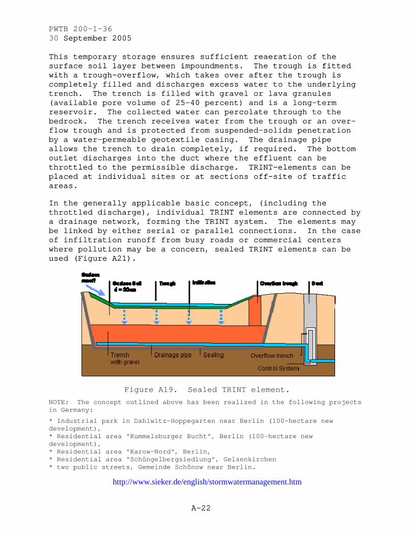
Figure A18 illustrates the technical principle of the four-component concept. Rain water feeds into an overgrown trough (for decontamination), which can store the discharge temporarily (K = ca 10-5 m/s) during impounding conditions. The trough empties through exfiltration a few hours after the rain ceases.
Overflow trench
Figure A18. Longitudinal section of a Trough Infiltration Trench (TRINT) Element.
(Used with permission.)
PWTB 200-1-36 30 September 2005September 2005
A-22
A-22
This temporary storage ensures sufficient reaeration of the surface soil layer between impoundments. The trough is fitted with a trough-overflow, which takes over after the trough is completely filled and discharges excess water to the underlying trench. The trench is filled with gravel or lava granules (available pore volume of 25-40 percent) and is a long-term reservoir. The collected water can percolate through to the bedrock. The trench receives water from the trough or an over-flow trough and is protected from suspended-solids penetration by a water-permeable geotextile casing. The drainage pipe allows the trench to drain completely, if required. The bottom outlet discharges into the duct where the effluent can be throttled to the permissible discharge. TRINT-elements can be placed at individual sites or at sections off-site of traffic areas.
This temporary storage ensures sufficient reaeration of the surface soil layer between impoundments. The trough is fitted with a trough-overflow, which takes over after the trough is completely filled and discharges excess water to the underlying trench. The trench is filled with gravel or lava granules (available pore volume of 25-40 percent) and is a long-term reservoir. The collected water can percolate through to the bedrock. The trench receives water from the trough or an over-flow trough and is protected from suspended-solids penetration by a water-permeable geotextile casing. The drainage pipe allows the trench to drain completely, if required. The bottom outlet discharges into the duct where the effluent can be throttled to the permissible discharge. TRINT-elements can be placed at individual sites or at sections off-site of traffic areas.
In the generally applicable basic concept, (including the throttled discharge), individual TRINT elements are connected by a drainage network, forming the TRINT system. The elements may be linked by either serial or parallel connections. In the case of infiltration runoff from busy roads or commercial centers where pollution may be a concern, sealed TRINT elements can be used (Figure A21).
In the generally applicable basic concept, (including the throttled discharge), individual TRINT elements are connected by a drainage network, forming the TRINT system. The elements may be linked by either serial or parallel connections. In the case of infiltration runoff from busy roads or commercial centers where pollution may be a concern, sealed TRINT elements can be used (Figure A21).
Overflow trench
Figure A19. Sealed TRINT element.
NOTE: The concept outlined above has been realized in the following projects in Germany:
* Industrial park in Dahlwitz-Hoppegarten near Berlin (100-hectare new development), * Residential area "Rummelsburger Bucht", Berlin (100-hectare new development), * Residential area "Karow-Nord", Berlin, * Residential area "Schüngelbergsiedlung", Gelsenkirchen * two public streets, Gemeinde Schönow near Berlin.
http://www.sieker.de/english/stormwatermanagement.htm

PWTB 200-1-36 30 September 2005
B-1
APPENDIX B
COMMERCIALLY AVAILABLE STORMWATER SYSTEMS
Stormcell® Storage System
This Hydro International system is an alternative to underground storage at low cost. It is lightweight and modular and can be rapidly constructed using an excavator and two operators. Stormcell® consists of a high void ratio (95 percent) plastic matrix produced in blocks. The plastic resists chemicals and microorganisms commonly found in stormwater, which helps alleviate rotting of the matrix. The matrix is made of vertically aligned polypropylene hexagonal tubes, enabling it to withstand occasional loads up to 40 tons per square meter, long-term design loads of 4 tons per square meter, and lateral loads up to 2 tons per square meter. The upper and lower matrix faces are covered with a nonwoven polyester fabric that prevents the intrusion of fines into the voids.
Stormcell® can be used beneath trafficked areas (Figure B1), and it provides structural support to the surface, reducing the cost of the road and car-park construction. If permeable paving is used above Stormcell®, the stormwater can seep into the storage facility and eliminate the need for stormwater drainage. Stormcell® can be used for both large- and small-capacity storage tanks. Its efficiency is enhanced by using also Hydro-Brake® Flow Control and Hydro’s Hydrological Analysis Service. See Appendix C for cost analysis.
Figure B1. Matrix of vertically aligned polypropylene hexagonal tubes.

PWTB 200-1-36 30 September 2005
B-2
Figure B2. Stormcell® installed beneath the surface.
(Used with permission.)
http://www.hydro-international.biz/us/stormwater_us/stormcell_casestudies.php
Advantages • Easy to install and retrofit • Modular and highly flexible • Lightweight but very strong • Allows phased implementation reducing cash flow needs • Can be used to provide very shallow storage tanks • Patented distribution pipework reduces situation potential
Applications • Source control • Storm attenuation in:
o New developments o Highway schemes o Car parks
• Alleviation of existing flooding in urban areas • Land drainage

PWTB 200-1-36 30 September 2005
B-3
• Soakaways • Rainwater storage for re-use
http://www.hydrointernational.biz/nam/storm_prod2.html
Grasspave2 – Porous Paving System
This paving system provides great load bearing strength in addition to protecting vegetation root systems from deadly compaction. The high void spaces within the entire cross-section allow excellent root development and storage capacity for stormwater. The stormwater’s movement slows down as it moves across and through Grasspave2 surfaces. The slowed movement allows sediment to deposit and increases time to discharge. Active soil bacteria consume suspended pollutants and some amounts of engine oils, which is aided by the system’s oxygen exchange capacity.
Grasspave2 is manufactured in 3.3 feet x 3 feet or 1.65 feet x 1.65 feet units and assembled into rolls. The system consists of a sandy gravel base course, Hydrogrow polymer-fertilizer mixture, the Grasspave2 ring and grid structure, sharp concrete sand, and grass seed or sod (Figure B3). It has a high compressive strength 5,721 psi and can be used for green firelanes; a firetruck exerts only about one-fifth of capacity.
The cost of Grasspave2 depends on the size of the project. For a 10,000 square-foot area, the cost would be about $3.15 per square foot, including gravel base layer, seeding, etc.
Figure B3. Grasspave2 includes a number of components. (Used with permission.)
Advantages • Pervious load bearing surface • Stormwater pollution filtration and treatment

PWTB 200-1-36 30 September 2005
B-4
• Airborne dust capture and retention • Heat energy reflection reduction • Tree growth within parking area Applications • Overflow parking • Firelanes • Driveways • Employee parking • Utility access • Emergency access • Infiltration basins
http://www.grasspave.com/GP2/grasspave.htm
http://www.buildinggreen.com/products/paving.cfm
http://www.toolbase.org/tertiaryT.asp?TrackID=&CategoryID=1438&DocumentID=2160
Rainstore3 – Underground Stormwater Detention, Retention, or Harvesting System
Rainstore3 can be used for underground stormwater storage. Each unit (Figure B4) is constructed from injection molded plastic, supports 36 vertical columns, and exceeds H-20 loading. The unit measures 3.28 feet x 3.28 feet x 4 inches high. The 94 percent void space provides storage for 25 gallons per unit.
Figure B4. One Rainstore3 unit. (Used with permission.)
Advantages • Allows development of valuable land resources by moving
stormwater ponds below ground

PWTB 200-1-36 30 September 2005
B-5
• Available pre-assembled in depths from 4 inches to 8 feet 4 inches
• 94 percent open for water storage • Virtually eliminates stone requirements • Easy installation Applications • Underground stormwater storage • Detention or retention systems • Water harvesting
http://www.grasspave.com/RS3/rainstore.htm
Gravelpave2 – Porous Paving System
Gravelpave2 provides heavy load bearing support and containment of gravel, creating a porous pavement surface with unlimited traffic volume and/or duration time for parking. If used with a proper porous base course material, Gravelpave2 provides a void space of 35 percent for storage volume of rainfall during rain events. An 8-inch deep cross-section would store 2.8 inches of rain. Although bacteria concentrations are lower than with Grasspave2, polluted runoff and vehicle drippings are consumed prior to reaching the water table. It is manufactured in 3.3 ft x 3.3 ft units or 1.65 ft x 1.65 ft units and assembled into rolls (Figure B5).
Figure B5. One unit of Gravelpave2. (Used with permission.)
Advantages • Pervious load bearing surface – unlimited traffic • Stormwater pollution filtration and treatment • Heat energy reflection reduction, “cool” surface • Tree growth within parking areas Applications • All parking aisles and bays

PWTB 200-1-36 30 September 2005
B-6
• Handicap parking spaces • Automobile and truck storage yards • All service and access drives/loading dock areas • Trails for multiple uses • Boat ramps • Outdoor bulk storage areas (lumber, steel, etc.) • Infiltration basins • High-use pedestrian areas
http://www.grasspave.com/GV2/gravelpave.htm
http://www.csupomona.edu/~la/la632/pave/jerry.pdf
Slopetame2 - Erosion Control System
Slopetame2 is a permanent three-dimensional (3D) reinforcement and stabilization matrix (Figure B6) suited for steep, vegetated slopes and channel banks. The integral rings, bars, grid, and fabric combine to contain upper root zone soils, while allowing vegetation roots to easily pass through and minimize movement and loss by rain or flowing water. Slopetame2 comes in rolls consisting of 3.3 feet x 3.3 feet units or 1.65 feet x 1.65 feet units with connections allowing the rolls to be fastened together forming one large continuous mat that covers the entire face of long slopes. The rolls can also be pre-vegetated by vibrating sod into rings (or growing custom plant mixes in mat by contract). This allows mats to be placed and anchored to slopes with established root systems, able to withstand intense rainfall or water flow immediately.
Figure B6. Slopetame2 matrix. (Used with permission.)

PWTB 200-1-36 30 September 2005
B-7
Advantages • True 3-D containment of fill for increased stability • Small-scale confinement with rings and bars prohibiting soil
movement • Shallow depth of fill material to reduce costs • Strong diagonal grid to disperse loads across slopes • Interlocked continuous structure across slopes for greater
strength • Strong root matrix in geotextile fabric for additional support • Fabric backing to reduce chance of undercutting and slow water
infiltration • Lightweight product for easy assembly • Ultraviolet (UV)-resistant • High durability and resistance to damage from normal
horticultural chemicals
Applications • Steep slope erosion control • Channel bank stabilization • Channel energy dissipation • Infiltration trenches • Vegetated swales and strips
http://www.grasspave.com/ST2/slopetame.htm
Draincore2 – Subsurface Drainage System
Draincore2 is a high volume drainage layer (Figure B7) that can withstand heavy loads in direct contact. The drainage core, wrapped in a geotextile fabric, allows water to enter from any direction, with the rings placed vertically or horizontally. Water can flow between rings in either vertical or lateral directions simultaneously. Draincore2 can distribute water at 58 gallons per minute (gpm) per foot width, twice the conveyance rate of a pipe and gravel system.

PWTB 200-1-36 30 September 2005
B-8
Figure B7. Draincore2 high volume drainage layer. (Used with permission.)
Advantages • High conveyance rate - 58 gpm per foot width • Flexible grid system to fit unusual contours • Provides insulating air layer from extreme temperatures • Efficient "void" space for heating or cooling systems • High compression strength - 5700 psi • Durable HDPE plastic
Applications • Infiltration basin collector and conveyance • Cutoff drain for surface and subsurface flow • Constructed wetlands • Foundation and retaining wall drainage • Roof deck and planter drainage • Sports turf drainage system • Landfill cap and/or drainage construction.
http://www.grasspave.com/DC2/draincore.htm
Total Stormwater Management System
The Kitsap County Fairgrounds Project (Washington) combined Grasspave2, Gravelpave2, Rainstore3, Draincore2, and Slopetame2 technologies to provide a total stormwater management system for a parking lot (Figure B8). The project is expected to cost around $700,000 ($725,388 [2004$]) about half the estimated $1.5 million ($1.55 million [2004$]) which was originally proposed for an asphalt parking lot with a concrete drainage system. During dry periods, the stored water will be used to irrigate the surrounding ballfields. Currently, it takes about 4 million

PWTB 200-1-36 30 September 2005
B-9
gallons of water a year to keep the ballfields green. By using the captured rainwater and excess runoff, it is estimated the consumption will be reduced to 2 million gallons (Dunagan 2003).
Figure B8. Total Stormwater Management. (Used with permission.)
http://www.grasspave.com/TSM/TSM.htm
http://www.thesunlink.com/redesign/2003-04-13/local/122275.shtml

PWTB 200-1-36 30 September 2005
B-10
StormTrap
Each StormTrap project is custom made to suit the specific requirements. Each Single TrapTM or Double TrapTM is a precast concrete modular unit that, when combined, form an underground detention system. Figure B9 shows units being assembled at a project. In this case, 30 Double Traps (5-feet dimension) were used to store 0.23 acre-feet of water. Table B1 shows data from projects using StormTrap.
Table B10. Data from projects using StormTrap.
Project Description of Traps No. of Traps
Total Volume of Water Stored
Steak-n-Shake 7 ft 0 in. Double Traps 32 0.16 acre-feet Minooka Retail
Center 3 ft 4 in. Single Traps 77 0.46 acre-feet
De Marco Plaza 4 ft 10 in. Single Traps 69 24,315 CF Walgreen’s 1 ft 6 in. Single Traps 48 12 acre-feet Gas City 2 ft 6 in. Single Traps 28 13 acre-feet
BMW Dealership 10 ft 0 in. Double Traps 108 45,300 CF Butterfield Park
District 10 ft 0 in. Double Traps 42 0.81 acre-feet
Target Super Store
4 ft 6 in. Single Traps 30 10,250 CF
http://www.stormtrap.com/
Green Solar CanopyTM
This technology incorporates the stormwater harvesting of a green roof with the air quality and energy production of a glazed solar panel (photovoltaic cells) canopy arching over the drive lanes. The glazed solar canopy produces clean electricity from sunlight while simultaneously allowing sufficient light to pass through (Figure B9).

PWTB 200-1-36 30 September 2005
B-11
Figure B9. Conceptual image of the Green Solar Canopy installed over a parking garage rooftop.
(Used with permission.)
http://www.thcahill.com/canopy.html
RAINSAVER
RAINSAVER is an Australian-developed rainwater storage system that replaces all gutter and stormwater systems and collects rainwater for household use. The system supplies gravity-fed water to the toilet and external faucets. A connection to the main water supply allows the RAINSAVER (Figure B10) to automatically top-up the system from the internal tap system during dry spells, and during extreme rainfall periods, a series of overflow holes placed around the house discharge the excess rainwater away from the house to infiltrate the yard. Estimated cost per household is $463.86 (2004$).

PWTB 200-1-36 30 September 2005
B-12
Figure B10. Flow diagram of stormwater disposal using RAINSAVER. (Used with permission.)
http://www.rainsaver.com.au/diagram.html

PWTB 200-1-36 30 September 2005
B-13
PERMAVOID
This stormwater management system is highly voided, high strength, creep resistant, and shallow. The system was designed for use in a variety of applications including the conveyance, attenuation (storage) and infiltration of stormwater. The primary components of the system are:
PERMAVOID - highly voided, high strength slender box units
PERMAVOID-TIE – creep-resistant interlocking ties
PERMAVOID-STRUT - void forming pedestals.
The PERMAVOID component is a high strength geocellular, highly voided, lightweight, interlocking plastic box structure, with integral diffusion facility and maintenance duct. The single unit dimensions are 708 mm long x 354 mm wide x 150 mm deep.
This portion of the system is a high strength, creep resistant locking component to provide lateral and vertical restraint between interlocked plastic box structures (PERMAVOID). The tie system prevents short and long-term (creep) deflection from static and imposed loads.
This is a space forming component interlocked between high strength box structures. The density of void forming pedestals can be adjusted to meet design loading criteria. Table B2 lists the functions and benefits of the PERMAVOID system.
Table B2. Functions and benefits of the PERMAVOID system.
FUNCTIONS BENEFITS
Subbase/ground improvement Reduction in excavation volumes
Lightweight fill Reduction in imported materials
Rainwater attenuation/infiltration Easy handling Water treatment Integral maintenance duct
Oil interception and treatment Contaminant retention Shallow storage Subgrade improvement
Structural Performance Standard PERMAVOID Unit Dimensions: 708 mm x 354 mm x 150 mm
Core Material: Polypropylene Volumetric Void: 92%
Effective Perforated Surface Area: 52% Max. Crush Strength within simple
constructed pavement:
>1400 kN/m2

PWTB 200-1-36 30 September 2005September 2005
B-14
B-14
The PERMASTRUTTM is designed for applications where site conditions restrict the plan area for installation, requiring a deeper construction. A network of PERMASTRUTTM units is located between layers of PERMAVOIDTM at predetermined centers to suit site-specific requirements.
The PERMASTRUTTM is designed for applications where site conditions restrict the plan area for installation, requiring a deeper construction. A network of PERMASTRUTTM units is located between layers of PERMAVOIDTM at predetermined centers to suit site-specific requirements.
http://www.permaceptor.com/http://www.permaceptor.com/
StormChambersTM StormChambersTM
StormChambers™ are open underneath, which allows for infiltration of stormwater, providing recharge of groundwater, mimicking pre-development stormwater runoff conditions. This system significantly contributes to low impact/sustainable development goals and watershed management. Figure B11 shows a diagram of the recommended system installation. Each chamber is built from high molecular weight/high density polyethylene. The side portal feed eliminates the need for manifold header pipe systems for feed and discharge. It also eliminates the additional excavation, stone, and associated labor costs. Figure B12 shows three chambers of StormChambersTM.
StormChambers™ are open underneath, which allows for infiltration of stormwater, providing recharge of groundwater, mimicking pre-development stormwater runoff conditions. This system significantly contributes to low impact/sustainable development goals and watershed management. Figure B11 shows a diagram of the recommended system installation. Each chamber is built from high molecular weight/high density polyethylene. The side portal feed eliminates the need for manifold header pipe systems for feed and discharge. It also eliminates the additional excavation, stone, and associated labor costs. Figure B12 shows three chambers of StormChambersTM.
Filter Fabric Against Trench Wall
4 ft x 7 ft Heavyweight Stabilization Netting Supplied
Figure B11. Diagram of the recommended installation of StormChambersTM system. (Used with permission.)
http://www.hydrologicsolutions.com/installation.html

PWTB 200-1-36 30 September 2005
B-15
Figure B12. Three units of StormChambersTM. (Used with permission.)
http://www.hydrologicsolutions.com/
Specifications of StormChamberTM
• Each unit will be 34.04 inches high, 60 inches wide, and 102.5 inches long.
• Lay-up length is 8.1 feet (start and end units) and 7.6 feet (middle unit).
• Each chamber will be formed from high molecular weight/high density polyethylene.
• Filter fabric between the soil and stone backfill layer and lining the side walls of the excavated area is required to prevent intrusion of soil or silt into the chambers and surrounding stone.
• Each chamber has 14 ribs approximately 3.6 inches high, 4.4 inches wide at the bottom, tapering to 3.8 inches at the top. Spacing of the ribs at the bottom of the chamber is approximately 4.9 inches and, at the top, approximately 3.2 inches. One smaller rib, sized dimensionally to effectively nest under and interlock to connect units, is 2.9 inches high, 3.3 inches wide at the top of the rib, and 4.1 inches wide at the base.
• Overall height to the inside rib is 30.44 inches. Overall height to the outside rib is 34.04 inches.
• Invert height for 12-inch pipe is 16.49 inches. Invert height for 10-inch pipe is 17.49 inches. Invert height for 8-inch pipe is 18.49 inches.
• Each unit has the ability to accept up to a 12-inch feed pipe in the unit’s side portal.

PWTB 200-1-36 30 September 2005
B-16
• Each unit is designed to handle 10 cubic feet of storage per lineal foot.
• Stone diameter will be 1.5 to 2 inches.
http://www.hydrologicsolutions.com/media/doc/StormChamber-Specifications.doc
GEOlight
GEOlight is a product of Sustainable Drainage Systems Ltd. It consists of thermoformed recycled PVC ultra-light honeycombed structure (ULHS), in the form of standard 1-m³ blocks of mean weight 50 kg/m³, which are used to create a stormwater management system (Figure B13). It provides underground plugged storage for a volume of stormwater, by incorporating specially manufactured impermeable membranes used for attenuation, or geotextiles for infiltration.
GEOlight is an embedded storage capacity providing water for areas suitable for roads, car parks, recreation grounds, or green spaces. The modular design makes GEOlight highly appropriate for all topographical areas and architectural requirements.
Figure B13. GEOlight is a thermoformed recycled PVC ultra-light honeycombed structure.
(Used with permission.)
http://www.hepworthdrainage.co.uk/zoned_area/default.asp

PWTB 200-1-36 30 September 2005
B-17
StormTech
The StormTech SC-740™ Chamber optimizes storage volumes in relatively small footprints. By providing 2.2 ft3/ft2 (minimum) of storage, the SC-740™ chambers can prevent excessive excavation, backfill, and associated costs (Table B3).
Table B3. Specifications for StormTech SC-740TM. NOMINAL CHAMBER SPECIFICATIONS
Chamber Size (W x H x Installed L)
51.0 in. x 30.0 in. x 85.4 in.
Chamber Storage 45.9 ft3 Chamber Weight 74.0 lb Minimum Installed Storage 74.9 ft3
The StormTech SC-310TM Chamber (Table B4) is suitable for Stormwater systems requiring low rise and wide span solutions. This low-profile chamber allows the storage of large volumes, 1.3 ft3/ft2 at minimum depths (Figure B14).
Table B4. Specifications for StormTech SC-310TM. NOMINAL CHAMBER SPECIFICATIONS
Chamber Size (W x H x Installed L)
34.0 in. x 16.0 in. x 85.4 in.
Chamber Storage 14.7 ft3 Chamber Weight 35 lb Minimum Installed Storage 31.0 ft3

PWTB 200-1-36 30 September 2005
B-18
Figure B14. StormTech chambers (left) SC-310™ and (right) SC-740™.
(Used with permission.)
http://www.stormtech.com/engineers/design_calculator.asp
http://www.stormtech.com/about.htm

PWTB 200-1-36 30 September 2005
C-1
APPENDIX C
REVIEW OF COSTS FOR ALTERNATIVE STORMWATER SYSTEMS
LOW IMPACT DEVELOPMENT (LID)
LID practices show both economic and environmental benefits in less disturbance of the development area, conservation of natural features, and potentially less expense than traditional stormwater control mechanisms. Savings for control mechanisms take into account not only construction, but long-term maintenance and life-cycle cost considerations. An alternative LID stormwater control design incorporating bioretention areas, compact weir outfalls, depressions, grass channels, wetland swales, and specially designed storm water basins, was used for a new 270 unit apartment complex in Aberdeen, NC. Construction phases were completed in 2000, 2003, and 2005. Nearly all of the subsurface collection systems associated with curb and gutter projects were eliminated. Using LID saved the builder 72 percent or $175,000 ($189,804.77 [2004$]) of the stormwater construction costs http://www.epa.gov/owow/nps/lid/lid.pdf.
LID Estimates
A developer dissatisfied with a conventional land plan used a different approach. The resulting design included the following cost information (Table C1). http://www.nahbrc.org/tertiaryR.asp?TrackID=&DocumentID=2007&CategoryID=1071
Table C1. Comparison of two different land plans.
PROJECTED RESULTS FROM TOTAL DEVELOPMENT Total Site Lot Yield LF – Street LF - Collector Street LF - Drainage Pipe Drainage Sections (Inlets, Boxes, Headwalls) Estimated Total Cost
Conventional Plan 358 21,770 7,360 10,098 103 $4.85 million (2004$)
Revised Green Plan 375 21,125 0 6,733 79 $4.11 million (2004$)

PWTB 200-1-36 30 September 2005
C-2
ACTUAL RESULTS FROM PHASE ONE Total Site (engineer’s estimate) Lot Yield Total Cost Cost Per Lot
Conventional Plan 63 $1,028,544 $17,221.52 (2004$)
Green Plan 72 $828,523 $12,138.19 (2004$)
ECONOMIC AND OTHER BENEFITS FROM LOW-IMPACT DEVELOPMENT
Higher Lot Yield Higher Lot Value Lower Cost per Lot Enhanced Marketability Added Amenities Recognition
17 additional lots $3,000 more per lot than competition $4,800 less per lot 80 percent of lots sold in first year 23.5 ac of green space/parks National, state, and professional groups
TOTAL ECONOMIC BENEFIT More than $2.32 million in savings
(2004$)
http://www.nahbrc.org/tertiaryR.asp?TrackID=&DocumentID=2007&CategoryID=1071
Bioretention Facilities
Sources indicate that bioretention facilities are less cost intensive than traditional structural stormwater conveyance systems. In Prince George’s County, MD, construction of a typical bioretention area is $5,000–$10,000 per acre drained, depending on soil type ($5,423–$10,846 [2004$]). Other sources estimate the costs for developing bioretention sites at $3–$15 per square foot ($3.25–$16.27 [2004$]) of bioretention area. Design guidelines (from Idaho Dept. of Environmental Quality, for example, and from Prince George’s County) recommend that bioretention systems occupy 5–7 percent of the drainage basin. Reduced construction costs for storm drainpipe are additional savings. At a medical office building in Prince George's County, bioretention practices reduced the amount of storm drain pipe from 800 feet to 230 feet, which resulted in a cost savings of $24,000 ($31,007 [2004$]) or 50 percent of the overall drainage cost for the site (Figure C1) (Dept. of Environmental Resources, Prince George’s County, MD). Annual maintenance is required for the overall success of bioretention systems, including maintenance of plant material, soil layer, and mulch layer.

PWTB 200-1-36 30 September 2005
C-3
Figure C1. Typical bioretention system (Dept. of Environmental Resources, Prince George’s County, MD).
Case Study Using Bioretention Techniques
The developer of an 80-acre residential community (Somerset, MD) with 199 homes on 10,000 square-foot lots used LID practices to manage stormwater. Each of the lots incorporates a rain garden with an overall estimated implementation cost of $100,000 ($103,627 [2004$]). This procedure eliminated the need for stormwater ponds, estimated to cost $400,000 ($414,507 [2004$]), and saved about $300,000 ($310,880 [2004$]). The LID method gained six additional lots and their associated revenues and reduced finished lot cost by approximately $4,000 ($4,145 [2004$]) (Hager 2003). Table C2 compares the costs for conventional design and bioretention system.

PWTB 200-1-36 30 September 2005
C-4
Table C2. Cost comparison of conventional design and bioretention system.
Description Conventional Design (2004$)
Bioretention System (2004$)
Engineering design 0 $113,989.63 Land reclamation (6 lots x $414,539.32 Net) 0 <$248,704.66>
Total costs $2,546,987.50 $1,597,368.90 Total costs (-Land Reclamation + Redesign Costs)
$2,546,987.50 $1,732,083.90
Total Cost Savings = $949,618.65 (2004$) Cost Savings Per Lot = $4,770.98 (2004$)
(Source: D. Winogradoff)
http://www.nahbrc.org/docs/MainNav/GreenBuilding/3833_Municipal-final-screen.pdf
Alternative Design at Fort Bragg (1993)
An alternative design for a parking area reduced the paved surface area 40 percent to 14.3 acres and increased the parking spaces from 420 to 520. The new design cost 20 percent less to build and saved $1.6 million ($2.07 million [2004$]). The revised design included grassed islands within parking areas and planting areas around buildings. The cost reductions were achieved through decrease in paved areas ($823,000) ($1,063,307 [2004$]); elimination of the 48-inch storm drain to the stream and other stormwater control revisions ($390,000) ($503,876 [2004$]); and reduction in earth excavated ($400,000) ($516,796 [2004$]).
http://www.main.nc.us/riverlink/content/07chap/chap07.htm#7.1.2
CONSTRUCTED WETLANDS
The two basic types of constructed wetlands are (Figure C2): • Subsurface systems that have no visible standing water
designed so that the stormwater flows through a gravel substrate beneath the surface vegetation.
• Surface flow systems that have standing water at the surface suited to larger constructed wetland systems, for example, those designed for municipal wastewater treatment.

PWTB 200-1-36 30 September 2005
C-5
Figure C2. Constructed wetlands: (a) free water surface constructed wetland and (b) vegetated submerged bed system.
http://www.epa.gov/ORD/NRMRL/pubs/625r99010/625r99010.pdf
Economic and Financial Analysis • Construction Costs - Using data from municipal systems, Kadlec
(1995) cites construction costs from 18 North American surface flow wetlands ranging from $6,000 ($7,352 [2004$]) to $300,000 ($367,647 [2004$]) per hectare (1994), with a mean of $100,000 ($122,549 [2004$]). Reed et al. (1995) cited a range of $100,000 ($126,103 [2004$]) to $240,000 ($302,648 [2004$]) per hectare for the same type of system ($30,000 per acre [1995$] for planning purposes). Land and gravel costs are major contributing factors.

PWTB 200-1-36 30 September 2005
C-6
• Operations and Maintenance (O&M) Costs - Once established, the O&M costs for constructed wetlands can be lower than for alternative treatment options, generally less than $1,500 per hectare/year (Kadlec 1995) ($1,838 per hectare/year [2004$]), including the cost of pumping, mechanical maintenance, and pest control.
http://www.cmhc-schl.gc.ca/en/imquaf/himu/wacon/wacon_066.cfm
Costs Associated with Constructed Wetlands
The Technical and Regulatory Guidance for Constructed Treatment Wetlands (December 2003) is another source for costs of con-structed wetlands. A variety of factors affect the cost of constructed wetlands: • detention time (climate dependent) • treatment goals • media type (deeper systems require less liner) • pretreatment type • number of cells (more cells require more hydraulic control
structures and liners) • source and availability of gravel media • terrain.
Capital Costs
The capital costs can be broken into excavation, liner, gravel, plants, distribution and control structures, fencing, and other. Generally, gravel costs constitute 40 to 50 percent of the cost of a 50,000 square-foot system. Gravel usually costs around $9.50/ton ($9.85/ton [2004$]) or $13.00/yd3 ($13.47/ yd3 [2004$]) throughout the United States. With hauling costs, however, delivered gravel can exceed $20.00/yd3 ($20.73 [2004$]). Liners cost about 15 to 25 percent of the total cost. Table C3 shows cost estimates of labor and materials for a liner for areas greater than 100,000 ft2. The information is based on competitive bids by liner installers who have more than 2 million square feet of installation experience.

PWTB 200-1-36 30 September 2005
C-7
Table C3. Liner costs for areas greater than 100,000 ft2.
Material Thickness Inch
Total cost, liner + installation (c/ft2) (2004$)
PVC 1.18 30.46-36.27 PE 1.57 36.27-51.81 PPE 1.57 46.63-51.81 Hypalon 2.36 62.17-72.54 XR-5 1.18 93.26 Reinforced PPE 1.77 56.99 PVC = polyvinylchloride; PE = polyethylene; PPE = polyphenylene ether; hypalon = chlorosulfonated polyethylene
Excavation/earthwork is usually the third or fourth largest cost and may amount to $1.50–$2.50 per cubic yard, which is $1.55–$2.59 in 2004 dollars. The cost varies with the terrain. Plants are a minor cost and run about $0.50–$1.00 ($0.52–$1.04 [2004$]) per plant. For 500,000-ft2 wetlands, plants placed in 3-foot centers at $0.50 ($0.52 [2004$]) each will cost about $2,800 ($2,902 [2004$]); whereas, plants grown on 18-inch centers will cost about $11,000 ($11,399 [2004$]). Other minor costs include piping and level control structures, flow distribution structures, flow meters, and fencing. Table C4 includes the costs associated with a typical 50,000 square-foot subsurface constructed wetland.
O&M costs include testing influent and effluent, weed control, flow distribution, and level adjustment sumps. Table C5 shows the cost comparisons of treatment systems over 20 years.
Table C4. Cost of a typical 50,000-ft2 subsurface constructed wetland.
Component Price/unit (2004$)
Total($) (2004$)
Percent of Total
Excavation/compaction $1.81/yd3 13,471.50 10.7 Gravel $16.58/yd3
53,782.38 42.6
Liner, 1.18 in. PC $0.36/ft2 19,948.19 15.8 Plants, 18-in. centers
$0.62/each 13,813.47 10.9
Plumbing 7,772.02 6.1 Control structures 7,253.89 5.7 Other 10,362.69 8.2 Total $126,404.14

PWTB 200-1-36 30 September 2005
C-8
Table C5. Cost comparisons of treatment systems over 20 years.
Option Capital (2004)
O&M (2004)
20-Year Total Cost (2004)
City of Omaha $855,958.54 $1,471,764.70 $2,819,460.10 Sequencing batch reactor
$618,341.96 $1,718,033.10 $2,781,232.10
Lagoon & sand filter
$769,533.67 $144,793.78 $1,468,377.20
Wetlands & sand filter
$378,549.22 $214,406.21 $865,297.40
http://www.itrcweb.org/WTLND-1.pdf
GRASS SWALES
Engineered swales are less costly than installing curb and gutter/storm drain inlet and storm drain pipe systems. The cost for traditional structural conveyance systems ranges from $40–$50 ($45.82-$57.27 [2004$]) per running foot. This is two to three times more expensive than an engineered grass swale (Center for Watershed Protection 1998). Open channels may be perceived as potential nuisance problems, may present maintenance problems, or may impact pavement stability. These problems can be alleviated by proper design, and the most significant maintenance requirements are periodic removal of sediments and mowing.
VEGETATED / GREEN ROOF COVERS
Vegetated roof covers offer benefits such as extending the life of roofs, reducing energy costs, and conserving valuable land that would otherwise be required for stormwater runoff controls.
http://www.epa.gov/owow/nps/lid/lid.pdf
Roof gardens typically have a life span of 50 years. They conserve energy by keeping roofs cool in summer and insulated in winter. Extensive green roofs cost between $5 and $12 per square foot ($5.42 and $13.15 [2004$]) to install. For roofs that need waterproofing, add another $10 to $12 per square foot ($10.85 to $13.02 [2004$]).
http://www.nrdc.org/water/pollution/storm/chap12.asp

PWTB 200-1-36 30 September 2005
C-9
PERMEABLE PAVEMENTS
Initial expenses for alternative paving materials may exceed those for conventional methods. The use of permeable pavers, however, often eliminates the requirement for underground storm drain pipes and conventional stormwater systems. The overall cost savings due to decreased investments in reservoirs, storm sewer extensions, and the repair and maintenance of storm drain systems should be considered.
Porous asphalt has been stated to cost about 10 percent more than the equivalent amount of nonporous asphalt. The porous asphalt, however, is part of the drainage system, and when the total cost of site development is added up, the permeable systems are predicted to produce savings of more than 30 percent in favorable sites (Ferguson 1996). Table C6 shows a range of cost estimates for permeable paver materials.
Table C6. A range of cost estimates for permeable paver materials.
Paver System Cost per Square Foot Installed (2004$)
Asphalt $0.52 to $1.04 Porous Concrete $2.08 to $6.75 Grass / gravel pavers $1.56 to $5.97 Interlocking Concrete Paving Blocks $5.19 to $10.38
Table found at: http://www.lid-stormwater.net/permeable_pavers/permpaver_costs.htm
http://www.penn-jersey.net/environmental_pavers.htm )
A more accurate price comparison would involve the costs of the full stormwater management paving system. For example, a grass/gravel paver and porous concrete representative stated that, when impervious paving costs for drains, reinforced concrete pipes, catch basins, outfalls, and stormwater connects are included, an asphalt or conventional concrete stormwater management paving system costs $9.50–$11.50 per square foot, which equals $9.87–11.94 in 2004 dollars; whereas, a permeable paving stormwater management system costs $4.50–$6.50 a square foot ($4.67–$6.75 [2004$]). The savings are considered to be even greater when pervious paving systems are calculated for their stormwater storage; if designed properly, they can eliminate retention pond requirements (Chere Peterson, PETRUS UTR, Inc., 2002, personal communication,

PWTB 200-1-36 30 September 2005
C-10
http://www.petrusutr.com/paving_paper.htm).
http://www.lid-stormwater.net/permeable_pavers/permpaver_costs.htm
Permeable pavement system types vary in cost and are initially more expensive than typical asphalt pavements. Cost comparisons between permeable pavement installations and conventional ponds or underground vaults are limited. Taking into account the elimination of conventional systems, reduced life-cycle costs, and maintenance costs, savings over the long term can be significant.
http://www.epa.gov/owow/nps/pavements.pdf
INFILTRATION TRENCHES
Infiltration trenches have a one-time capital cost and recurring maintenance costs. Table C7 shows estimates for an infiltration trench 478.4 square yards. In addition, sediment/oil removal would cost about $4,500 per year and grass cutting would be about $150 per year.
Table C7. Capital costs for infiltration trench.
Capital Costs Amount Unit Cost Cost USD (2004)
Filter Cloth 478.4 yd2 $7.43/yd2 $3,554.51Pervious Pipes 16(21.87 yd) $13.62/yd $4,753.42Sand Filter 104.64 yd3 $28.35/yd3 $2,970.89Gravel Storage 209.3 yd3 $28.35/yd3 $5,941.77Excavation 941.7 yd3 $6.80/yd3 $6,417.11Overflow Pipe 21.87 yd $163.53/yd $3,554.51Seed and Topsoil 478.4 yd2 $1.86/yd2 $891.27Observation Wells 2.2 yd $122.65/yd $267.38TOTAL $28,372
http://cmhc-schl.gc.ca/en/imquaf/himu/wacon/wacon_026.cfm
http://www.onlineconversion.com/length.htm
RETENTION PONDS
Retention or wet ponds maintain a permanent pool of water in addition to temporary storage of stormwater. Retention ponds add to the quality of stormwater through: • Gravitational settling of suspended particles • Biological uptake of pollutants by plants, algae, and bacteria • Decomposition of some pollutants.

PWTB 200-1-36 30 September 2005
C-11
Retention ponds are among the most expensive methods of managing stormwater. Table C8 shows the associated costs. The four main costs associated with installing and operating a retention pond are: • One-time capital costs • One-time installation costs • Recurring maintenance costs • Recurring waste disposal costs.
Table C8. Costs associated with retention ponds.
Cost Category Type of Cost US/Unit (2005$)
Capital Costs Rip Rap (Inlet/Spill) Riser Outlet Pipe (Concrete, 17.72 in.)
$8.53/yd2 $1,535.71-$6,142.82 $193.90/yd)
Installation Costs
Excavation Earthworks Vegetation (Aquatic & Terrestrial)
$7.8/yd3 $2.68/yd2
$0.70/yd2
Maintenance Costs
Landscaping Sediment Removal (every 10 years) Removal labor
$1.42/yd2 $0.70/yd2
$102.38/h
Disposal Costs Sediment Disposal $3.90/yd3
(Source: Ontario 1991.)
http://www.cmhc-schl.gc.ca/en/imquaf/himu/wacon/wacon_029.cfm
http://hemsidor.torget.se/users/b/bohjohan/convert/conv_e.htm#area
HIGH DENSITY POLYTHYLENE (HDPE) PIPE
Plastic pipe, HDPE and PVC, are cheaper to manufacture and, being lighter, can be easier to place on location. Representative costs are in Table D1 in Appendix D.
AQUIFER STORAGE AND RECOVERY
Aquifer storage and recovery (ASR) involves both recharge to an aquifer and recovery from the aquifer for subsequent use. Artificial recharge facilities include infiltration basins (spreading basins), infiltration galleries (recharge trenches), vadose zones recharge wells (dry wells) and combination

PWTB 200-1-36 30 September 2005
C-12
groundwater recharge/recovery wells (Figure C3). According to Stephens and Associates (2002), the use of ASR to manage water resources is increasing, particularly in the arid Southwest. In the Jemez y Sangre region, ASR is applicable to (1) bank water (inject surface waters for retrieval at a later time), (2) treat wastewater and inject as artificial recharge, and (3) manage stormwater.
Costs to implement ASR may include: • Pilot testing costs • Land acquisition costs • Influent water pretreatment costs • Environmental permitting costs • O&M costs.
Infiltration basins are usually the least expensive option, led by recharge trenches and vadose zone wells. Groundwater recharge wells are the most expensive. Table C9 shows costs for a system of infiltration basins at three projects in Arizona.
Table C9. Example of infiltration basin costs.
Approximate Project Costsa (2004$)
Project Name
No. of Basins
Total Basin Acreage
Infiltration Rate
(ac-ft/yr) Design Construction O&M
GRUSPb 6 211 100,000 NA NA 259,605/yr
CAVSARPc 9 290 100,000 4.79 ft 24.43 ft NA
Sweetwaterc 4 14 14,000 1.837 ft 5.51 ft NA a Does not include delivery pipeline, recovery wells, monitoring network, or O&M costs. b Granite Reef Underground Storage Project (Lluria 1999; Herman Bouwer, personal communication, 2002). c Central Aura Valley Storage and Recovery Project and Sweetwater Project information from Marie Light (Tucson Water), personal communication, 1999. af/yr = acre-feet per year; O&M = Operation and Maintenance; NA = Not available

PWTB 200-1-36 30 September 2005
C-13
Figure C3. Artificial recharge facilities.
(Used with permission.)
http://www.dbstephens.com/project_plans/Section5.pdf
STORMTECH COST CALCULATIONS
Table C10 shows the StormTech system calculator and a theoretical calculation.
Table C10. StormTech system calculator. PLEASE NOTE: This site calculator uses a 40% porosity within the stone. Site Calculator Enter the Required Storage Volume and select a StormMaster system and the calculator will approximate the total system size and cost needed. Top of Form Required Storage Volume:
1000ft3 javascript: void 0
StormTech Systems: RSC - 740
eset
StormTech Volume per Chamber:
74.9 CF w /6" of stone below
Number of Chambers Needed:
14
Required Bed Size: * 520.52ft2
Quantity of Stone: * 41.58Yds3
58.52Tons
Volume of Excavation: * 86.24Yds3
Area of filter fabric: * 63.62Yds2
Quantity Cost1 Total

PWTB 200-1-36 30 September 2005
C-14
Chambers: 14 $
185.0 / unit** $
2,590.00
Stone: $ / ton $12.0058.52 702.24
Excavation: $ / yard $5.0086.24 431.20
Filter Fabric: $ / yard $0.50 31.8163.62
1Call 1-888-296-5367 for estimated chamber pricing.
Subtotal
$3,754.00
Cost per ft3 $3.75
* includes 10% overage for bed perimeter For general estimate purposes only. Contact Stormtech for costs on specific projects and associated variables. Does not reflect changes in geographical costs or contractors overhead, profit, and other miscellaneous expenses. **C hamber costs may not be inclusive of shipping.
http://www.ads-pipe.com/us/en/technical/sitecalc.shtml
The user inputs the Required Storage Volume and selects a StormTech system and the calculator estimates the total system size and cost. For SC-740, the cost of $185.00/unit was obtained via telephone.
PWTB 200-1-36 30 September 2005
C-15
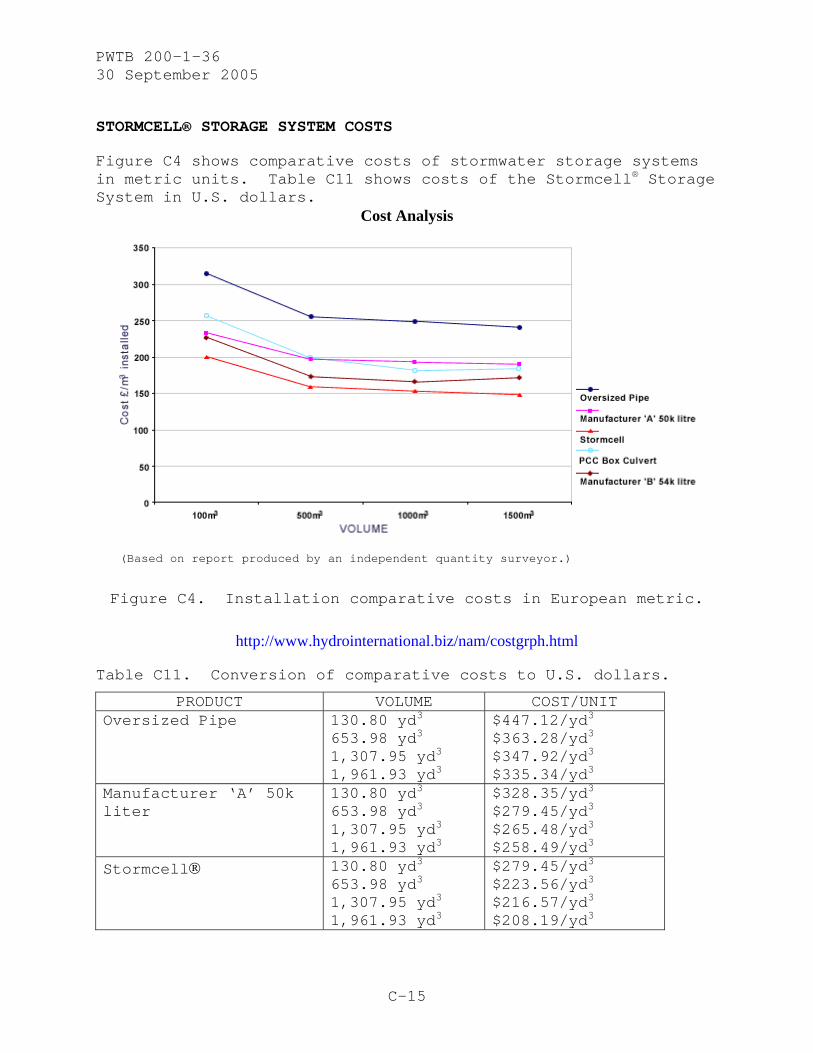
STORMCELL® STORAGE SYSTEM COSTS
Figure C4 shows comparative costs of stormwater storage systems in metric units. Table C11 shows costs of the Stormcell® Storage System in U.S. dollars.
Cost Analysis
(Based on report produced by an independent quantity surveyor.)
Figure C4. Installation comparative costs in European metric.
http://www.hydrointernational.biz/nam/costgrph.html
Table C11. Conversion of comparative costs to U.S. dollars.
PRODUCT VOLUME COST/UNIT Oversized Pipe 130.80 yd3
653.98 yd3 1,307.95 yd3
1,961.93 yd3
$447.12/yd3 $363.28/yd3 $347.92/yd3
$335.34/yd3 Manufacturer ‘A’ 50k liter
130.80 yd3 653.98 yd3
1,307.95 yd3
1,961.93 yd3
$328.35/yd3
$279.45/yd3
$265.48/yd3
$258.49/yd3
Stormcell® 130.80 yd3 653.98 yd3
1,307.95 yd3
1,961.93 yd3
$279.45/yd3
$223.56/yd3
$216.57/yd3
$208.19/yd3

PWTB 200-1-36 30 September 2005
C-16
PRODUCT VOLUME COST/UNIT PCC Box Culvert 130.80 yd3
653.98 yd3
1,307.95 yd3
1,961.93 yd3
$356.30/yd3 $279.45/yd3 $272.47/yd3 $273.86/yd3
Manufacturer ‘B’ 54k liter
130.80 yd3
653.98 yd3 1,307.95 yd3
1,961.93 yd3
$321.37/yd3 $241.73/yd3 $237.53/yd3 $244.52/yd3
http://www.oanda.com/convert/classic
http://www.onlineconversion.com/length.htm
GEOlight COSTS
Table C12 shows comparative costs for GEOlight. The costing was compiled by an independent cost consultant using data provided directly by the companies who supply the products.
Table C12. Comparative costs for GEOlight (2005$).
System Type Installation Costs per Cubic Meter*
of Storage 100 m 500 m 1000 m SDS GEOlight 200 $318.89 $285.23 $260.43 SDS GEOlight 400 $336.60 $301.17 $274.60 Modular System 1 $372.04 $310.03 $283.46 Modular System 2 $380.89 $318.89 $301.17 Tubular tank $389.75 $327.75 $310.03 Precast concrete pipes $425.18 $363.18 $345.46 HDPE large pipes $442.90 $398.61 $380.89
*excavating and backfill not included
http://www.nroltd.freeserve.co.uk/sds/price.htm
http://www.oanda.com/convert/classic
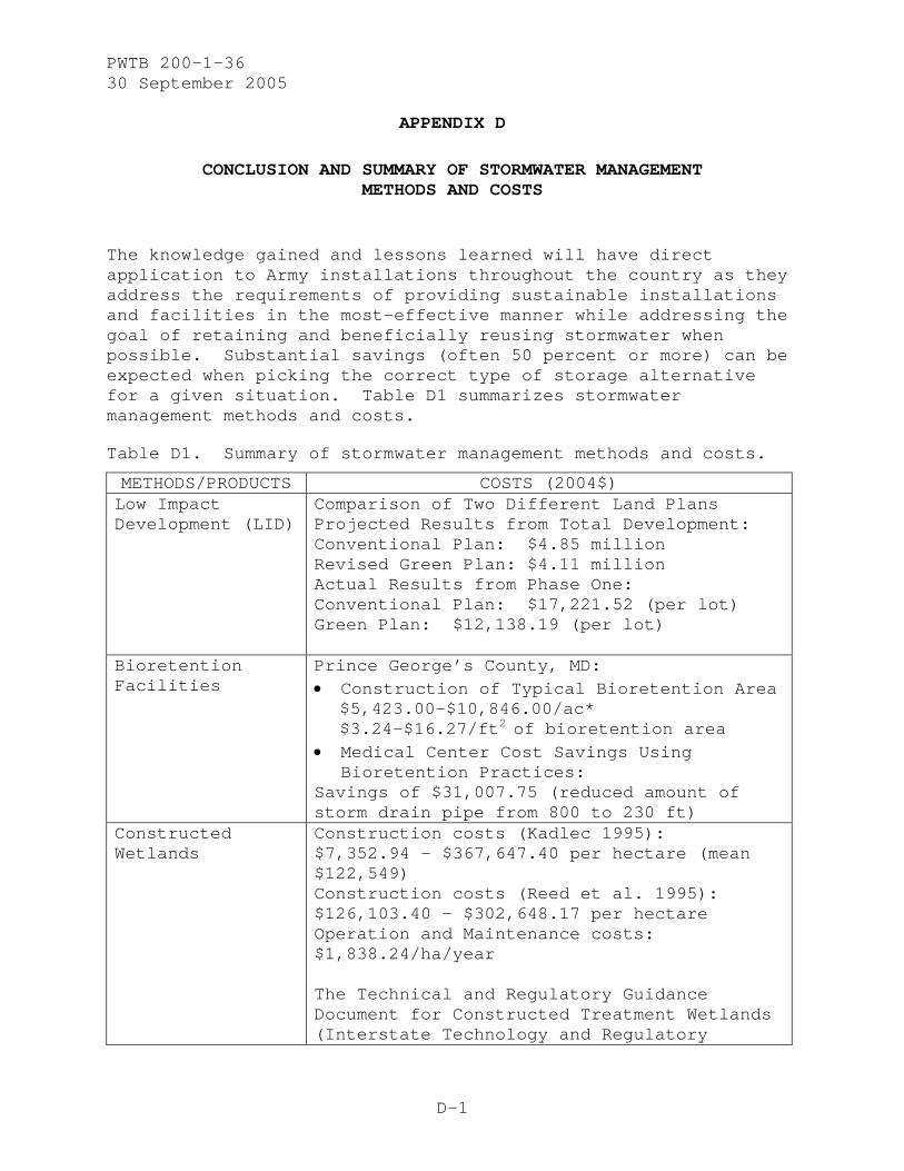
PWTB 200-1-36 30 September 2005
D-1
APPENDIX D
CONCLUSION AND SUMMARY OF STORMWATER MANAGEMENT METHODS AND COSTS
The knowledge gained and lessons learned will have direct application to Army installations throughout the country as they address the requirements of providing sustainable installations and facilities in the most-effective manner while addressing the goal of retaining and beneficially reusing stormwater when possible. Substantial savings (often 50 percent or more) can be expected when picking the correct type of storage alternative for a given situation. Table D1 summarizes stormwater management methods and costs.
Table D1. Summary of stormwater management methods and costs.
METHODS/PRODUCTS COSTS (2004$) Low Impact Development (LID)
Comparison of Two Different Land Plans Projected Results from Total Development: Conventional Plan: $4.85 million Revised Green Plan: $4.11 million Actual Results from Phase One: Conventional Plan: $17,221.52 (per lot) Green Plan: $12,138.19 (per lot)
Bioretention Facilities
Prince George’s County, MD: • Construction of Typical Bioretention Area
$5,423.00-$10,846.00/ac* $3.24-$16.27/ft2 of bioretention area
• Medical Center Cost Savings Using Bioretention Practices:
Savings of $31,007.75 (reduced amount of storm drain pipe from 800 to 230 ft)
Constructed Wetlands
Construction costs (Kadlec 1995): $7,352.94 - $367,647.40 per hectare (mean $122,549) Construction costs (Reed et al. 1995): $126,103.40 - $302,648.17 per hectare Operation and Maintenance costs: $1,838.24/ha/year The Technical and Regulatory Guidance Document for Constructed Treatment Wetlands (Interstate Technology and Regulatory
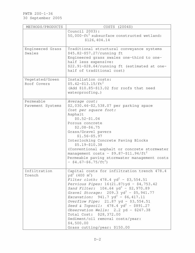
PWTB 200-1-36 30 September 2005
D-2
METHODS/PRODUCTS COSTS (2004$) Council 2003): 50,000-ft2 subsurface constructed wetland:
$126,404.14
Engineered Grass Swales
Traditional structural conveyance systems $45.82-$57.27/running ft Engineered grass swales one-third to one-half less expensive: $22.91-$28.64/running ft (estimated at one-half of traditional cost)
Vegetated/Green Roof Covers
Installation costs: $5.42-$13.15/ft2 (Add $10.85-$13.02 for roofs that need waterproofing.)
Permeable Pavement Systems
Average cost: $2,030.46-$2,538.07 per parking space Cost per square foot: Asphalt
$0.52-$1.04 Porous concrete
$2.08-$6.75 Grass/Gravel pavers
$1.56-$5.97 Interlocking Concrete Paving Blocks
$5.19-$10.38 (Conventional asphalt or concrete stormwater management costs - $9.87-$11.94/ft2
Permeable paving stormwater management costs- $4.67-$6.75/ft2)
Infiltration Trench
Capital costs for infiltration trench 478.4 yd2 (400 m2) Filter cloth: 478.4 yd2 - $3,554.51 Pervious Pipes: 16(21.87)yd - $4,753.42 Sand Filter: 104.64 yd3 - $2,970.89 Gravel Storage: 209.3 yd3 - $5,941.77 Excavation: 941.7 yd3 - $6,417.11 Overflow Pipe: 21.87 yd - $3,554.51 Seed & Topsoil: 478.4 yd2 - $891.27 Observation Wells: 2.2 yd - $267.38 Total Cost: $28,372.00 Sediment/oil removal costs/year: $4,500.00 Grass cutting/year: $150.00

PWTB 200-1-36 30 September 2005
D-3
METHODS/PRODUCTS COSTS (2004$)
Retention Ponds Capital Costs: Rip Rap - $10.19/yd2
Riser - $1,833.88-$7,335.51 Outlet Pipe - $231.55/yd
Installation Costs: Excavation - $9.34/yd3
Earthworks - $3.11/yd3
Vegetation - $0.85/yd2
Maintenance Costs: Landscaping - $1.70/yd2
Sediment Removal - $0.85/yd2
Removal Labor - $122.32 h Disposal Costs:
Sediment Disposal - $46.67/yd3
Pipe – Detention/ Retention Systems
Price per linear foot of pipe (includes trenching and bedding [6 inches of bedding under the pipe and 2 feet of cover above the pipe]): 24-inch HDPE - $21.15 24-inch reinforced concrete – $48.85 24-inch steel – $65.90 36-inch HDPE – $35.11 36-inch reinforced concrete – $112.86 36-inch steel – $110.01 48-inch HDPE – $57.19 48-inch reinforced concrete – $167.45 48-inch steel $206.80
Geosynthetics Geotextile – Installed costs range from $0.71-$0.92 per yd2.
Geogrids – Cost comparison for construction of site access road (1093.61 yd L/10.40 yd W): Conventional System $896,942.00 Geogrid System $771,812.00
Cost estimates (per yd2): Geomembranes - $11.98
Geotextiles - $1.33 Geocomposites - $2.66 Geonets - $2.66 Geogrids - $6.66
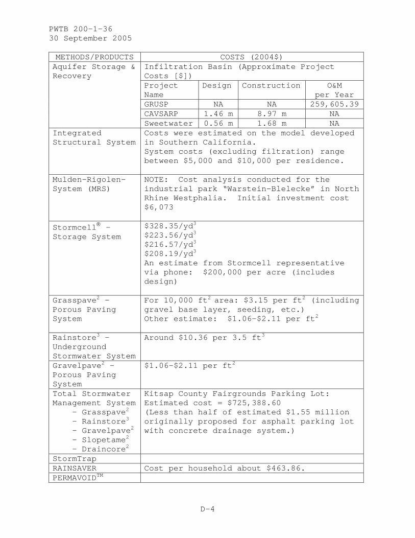
PWTB 200-1-36 30 September 2005
D-4
METHODS/PRODUCTS COSTS (2004$) Infiltration Basin (Approximate Project Costs [$]) Project Name
Design Construction O&M per Year
GRUSP NA NA 259,605.39CAVSARP 1.46 m 8.97 m NA
Aquifer Storage & Recovery
Sweetwater 0.56 m 1.68 m NA Integrated Structural System
Costs were estimated on the model developed in Southern California. System costs (excluding filtration) range between $5,000 and $10,000 per residence.
Mulden-Rigolen-System (MRS)
NOTE: Cost analysis conducted for the industrial park “Warstein-Blelecke” in North Rhine Westphalia. Initial investment cost $6,073
Stormcell® - Storage System
$328.35/yd3
$223.56/yd3
$216.57/yd3
$208.19/yd3
An estimate from Stormcell representative via phone: $200,000 per acre (includes design)
Grasspave2 – Porous Paving System
For 10,000 ft2 area: $3.15 per ft2 (including gravel base layer, seeding, etc.) Other estimate: $1.06-$2.11 per ft2
Rainstore3 – Underground Stormwater System
Around $10.36 per 3.5 ft3
Gravelpave2 – Porous Paving System
$1.06-$2.11 per ft2
Total Stormwater Management System - Grasspave2
- Rainstore3
- Gravelpave2
- Slopetame2
- Draincore2
Kitsap County Fairgrounds Parking Lot: Estimated cost = $725,388.60 (Less than half of estimated $1.55 million originally proposed for asphalt parking lot with concrete drainage system.)
StormTrap RAINSAVER Cost per household about $463.86. PERMAVOIDTM

PWTB 200-1-36 30 September 2005
D-5
METHODS/PRODUCTS COSTS (2004$) StormChambersTM
GEOlight200 100 meters $332.89 500 meters $297.75 1000 meters $271.86
GEOlight
GEOlight400 100 meters $351.39 500 meters $314.39 1000 meters) $286.66
StormTech Cost for StormTech SC-740: $185.00/unit $3.75/ft3

PWTB 200-1-36 30 September 2005
E-1
APPENDIX E
REFERENCES
Adams, Michele C. “Porous Asphalt Pavement with Recharge Beds: 20 Years & Still Working.” Stormwater, Volume 4 Number 3, May/June 2003. http://www.forester.net/sw_0305_porous.html
“Alternative Stormwater Management Practices for Residential Projects - Constructed Wetlands.” http://www.cmhc-schl.gc.ca/en/imquaf/himu/wacon/wacon_066.cfm
“Alternative Stormwater Management Practices for Residential Projects – Infiltration Trenches.” http://www.cmhc-schl.gc.ca/en/imquaf/himu/wacon/wacon_026.cfm
“Alternative Stormwater Management Practices for Residential Projects – Retention Ponds.” http://www.cmhc-schl.gc.ca/en/imquaf/himu/wacon/wacon_029.cfm
“Approximate HDPE Pipe Fusion Production/Cost Guideline.” Crow Company http://www.hdpe.com/Products/Cost/cost.html
“Aquifer Storage and Recovery (ASR).” Protecting the Environment. http://cweb.salisbury.sa.gov.au/manifest/servlet/page?pg=735&stypen=html
“Better Parking-Lot Design – Fort Bragg, NC.” Strategies in the Southeast, Chapter 7. http://www.main.nc.us/riverlink/content/07chap/chap07.htm
Bohnhoff, William. W. “Turning a Problem into an Asset,” Environmental Protection (April 2003), pp 39-43.
Brzozowski, Carol. “Options for Urban Stormwater Treatment.” Stormwater Jan/Feb 2004. http://www.forester.net/sw_0401_options.html
Brzozowski, Carol. “Stormwater Underground,” Stormwater July/August 2003. http://www.surfaceh20.org/sw_0307_stormwater.html
“Builder’s Guide to Low Impact Development.” http://www.nahbrc.org/docs/MainNav/GreenBuilding/3832_Builder-final-screen.pdf

PWTB 200-1-36 30 September 2005
E-2
Cahill, Thomas H., Michele Adams, and Courtney Marm. “Porous Asphalt – The Right Choice for Porous Pavements,” Hot Mix Asphalt Technology (September/October 2003), pp 26-40.
Combigrid® and Secugrid® http://www.naue.com http://www.naue.com/english/produkte/frame/secugrid.html
Cultec http://www.cultec.com/
“Design Manual for Use of Bioretention in Stormwater Management, Prince George's County, Maryland.” Prince George's County, Department of Environmental Resources. 1993. Department of Environmental Resources, Division of Environmental Management, Watershed Protection Branch.
“Designing Sustainable Environments.” Integrated Infrastructure Inc. http://www.3i-s.com/tech.html
Draincore2 Subsurface Drainage System http://www.grasspave.com/DC2/draincore.htm
Dunagan, Christopher. “Fairgrounds to redefine term ‘parking lot.’” http://www.thesunlink.com/redesign/2003-04-13/local/122275.shtml
England, Gordon. “The Use of Ponds for BMPs.” Stormwater July/August 2001 Volume 2(5). http://www.forester.net/sw_0107_use.html
“Environmentally Green…Economically Green, Tools for a Green Land Development Program,”National Association of Home Builders (NAHB) July 2001. http://www.nahbrc.org/tertiaryR.asp?TrackID=&CategoryID=1652&DocumentID=3475
“Fact Sheet – Detention Tanks and Vaults.” U.S. Department of Transportation Federal Highway Administration. http://www.fhwa.dot.gov/environment/ultraurb/3fs6.htm
Ferguson, B.K. “Preventing the problems of urban runoff.” Washington Water RESOURCE, the quarterly report of the Center for Urban Water Resources Management, 7(4) Fall 1996.
“Field Evaluation of Permeable Pavements for Stormwater Management.” United States Environmental Protection Agency. EPA-841-B-00-005B, October 2000. http://www.epa.gov/owow/nps/pavements.pdf

PWTB 200-1-36 30 September 2005
E-3
Forbes, Jeffrey, Herman Bouwer, Susan C. Kery, Ernest Atencio, et al. “Alternative: Aquifer Storage and Recovery. Jemez y Sangre Water Plan Alternatives Assessment. July 2002. http://edivision.lanl.gov/Downloads/waterissues_whitepapers/12_AquiferStrg-Recvry_TF.pdf
“French Drains.” IHBC Technical Sub-Committee Paper. http://www.ihbc.org.uk/Technical%20Papers/French%20Drains.htm
Gangnes, Drew A. “2004 Building Green.” Seattle Daily Journal of Commerce online edition. March 11, 2004. http://www.djc.com/news/en/11154643.html?query=cost+comparison&searchtype=all
“Geotextile Enhanced Unpaved Roads.” http://www.geotextile.com/case/pdf/case5.pdf
Goldstein, Natalie. “Constructed Wetlands for Erosion Control.” Erosion Control. May/June 2001. http://www.forester.net/ec_0105_constructed.html
Grasspave2 Porous Paving System (April 2003) http://www.eponline.com and http://www.grasspave.com/GP2/grasspave.htm
Gravelpave2 Porous Paving System http://www.grasspave.com/GV2/gravelpave.htm
“Guides to Low Impact Development.” ToolBase Services. http://www.toolbase.org/tertiaryT.asp?TrackID=&DocumentID=3834&CategoryID=36
Hager, Mary Catherine, “Low-Impact Development.” Stormwater, January/February 2003. http://www.forester.net/sw_0301_low.html
“Industry Urges Use of Steel Culvert in State Highway Projects.” http://www.ohiosteel.org/homepage/Culvert_Release.htm
Kadlec, R.H., “Overview: Surface flow constructed wetlands.” Water Science and Technology, 1995, 32(3):1-12.
Kellems, Barry L., Randall Johnson, and Fabian Sanchez. “Design of Emerging Technologies for Control and Removal of Stormwater Pollutants.” Submitted for Presentation at Water World & Environmental Resources Congress, Philadelphia, PA, June 2003. http://hartcrowser.com/pdfs/Stormwater_Abstract.pdf

PWTB 200-1-36 30 September 2005
E-4
Lehner, Peter H., George P. Aponte Clarke, Diane M. Cameron, and Andrew G. Frank. Stormwater Strategies, Chapter 12 The Low Impact Development Approach, May 1999. http://www.main.nc.us/riverlink/content/12chap/chap12.htm
“Low Impact Development.” Natural Resources Defense Council: Stormwater Strategies – Chapter 12. August 2001. http://www.nrdc.org/water/pollution/storm/chap12.asp
“Low Impact Development (LID).” United States Environmental Protection Agency. EPA-841-B-00-005, October 2000. http://www.epa.gov/owow/nps/lid/lid.pdf
“Low Impact Development (LID) Practices for Stormwater Management.” National Association of Home Builders (NAHB). http://www.nahbrc.org/tertiaryR.asp?TrackID=&DocumentID=2007&CategoryID=1071
“Natural Approaches to Stormwater Management.” The Journal for Municipal Solid Waste Professionals. March 2003. http://www.forester.net/mw_about.html
Ontario Ministry of the Environment, Stormwater Quality Best Management Practices (1991).
“Paving with Grass.” Environmental Building News 3(4) July/August 1994. http://www.buildinggreen.com/products/paving.cfm
“Permeable Pavement.” ToolBase Services http://www.toolbase.org/tertiaryT.asp?TrackID=&CategoryID=1438&DocumentID=2160
“Permeable Paver Costs.” http://www.lid-stormwater.net/permeable_pavers/permpaver_costs.htm
“Pervious Paving Alternatives.” Petrus UTR, Inc. http://www.petrusutr.com/paving_paper.htm
“Pipe Construction and Materials.” Wastewater Technology Fact Sheet. EPA 832-F-00-068 September 2000. http://www.epa.gov/owm/mtb/pipe_construction.pdf
Rainsaver – The revolutionary water conservation and stormwater control device. http://www.rainsaver.com.au/brochure1.html
Rainstore 3 Underground Stormwater Detention, Retention, or Harvesting System http://www.grasspave.com/RS3/rainstore.htm

PWTB 200-1-36 30 September 2005
E-5
Reed, S.C., R.W. Crites, and E.J. Middlebrooks. Natural Systems for Waste Management and Treatment, 2nd Ed., 1995. McGraw-Hill, Inc., New York.
Sieker, Friedhelm. “On-site stormwater management as an alternative to conventional sewer systems: a new concept spreading in Germany.” Water Science and Technology 38:10 (1998) 65-71. http://www.iwaponline.com/wst/03810/wst038100065.htm
Sieker, Friedhelm. “Principles of on-site storm water management.” http://www.sieker.de/english/stormwatermanagement.htm
Slopetame2 Erosion Control System http://www.grasspave.com/ST2/slopetame.htm
Source Control Technologies http://www.selenvironmental.com/stormwater/source%20control.htm
Stormcell® Storage System http://www.hydrointernational.biz/nam/storm_prod2.html
StormChambersTM http://www.hydrologicsolutions.com/installation.html
StormTech Chambers Technical Support. http://www.ads-pipe.com/us/en/technical/stormtech.shtml
StormTech Cost Comparison http://www.ads-pipe.com/us/en/technical/sitecalc.shtml
StormTech Detention, Retention, Recharge http://www.stormtech.com/about.htm
StormTrap Precast Concrete Modular Storm Water Detention http://www.stormtrap.com/
Stormwater Source Controls: Preliminary Design Guidelines Interim Report – Appendix A, 2004, p 28. http://www.gvrd.hc.ca/sewerage/pdf/Appendix_A_Stormwater_Source_Controls.pdf
“Storm Water Management” Pacific Corrugated Pipe Co. http://www.pac-corr-pipe.com/PDF_Files/swm_p3.pdf and http://www.pac-corr-pipe.com/detentio.htm

PWTB 200-1-36 30 September 2005
E-6
“Stormwater Management at Industrial Sites,” Water Quality Protection Note (November 2002), pp 1-4. Water and Rivers Commission (Government of Western Australia) http://www.wrc.wa.gov.au
Stormwater Retrofits in Urbanized Watersheds: Retrofit for Water Quantity and Quality Benefits. Cahill and Associates http://www.thcahill.com/retrofit.html
“Stormwater Strategies – The Economic Advantage.” Stormwater January/February Volume 2(1). http://www.forester.net/sw_0101_stormwater.html
Structural Stormwater Technologies: Porous Asphalt with Subsurface Infiltration/Storage Bed. Cahill Associates http://www.thcahill.com/pasphalt.html
Structural Stormwater Technologies: Porous Concrete with Subsurface Infiltration/Storage Bed. Cahill Associates http://www.thcahill.com/pconcrete.html
Sustainable Urban Drainage (SUDS) http://www7.caret.cam.ac.uk/guide_suds.htm
“Technical and Regulatory Guidance Document for Constructed Treatment Wetlands.” Prepared by The Interstate Technology & Regulatory Council Wetlands Team. December 2003 (pp 88-95). http://www.itrcweb.org/WTLND-1.pdf
Tilton, Joseph Lynn. “Helping Stormwater Keep Its Place,” Stormwater September/October 2002. http://www.forester.net/sw_0209_helping.html
Total Stormwater Management http://www.grasspave.com/TSM/TSM.htm
Traver, Robert, Andrea Welker, Clay Emerson, Michael Kwiatkowski, Tyler Ladd, and Leo Kob. Villanova Urban Stormwater Partnership: Porous Concrete.” Stormwater July/August 2004 Volume 5 Number 4. http://www.forester.net/sw_0407_villanova.html
“Underground Detention.” Georgia Stormwater Management Manual (3.4-13) Volume 2 (Technical Handbook) http://www.georgiastormwater.com/vol2/3-4-3.pdf
“Using Low-Impact Development in Stormwater Management.” Water Environment Research Foundation, Winter 2001. http://www.werf.org/press/winter01/01w_low.cfm

PWTB 200-1-36 30 September 2005
E-7
Vegetated Stormwater Technologies: Constructed Wetlands and Infiltration/Water Quality Swales. Cahill and Associates http://www.thcahill.com/wetlands.html
Vegetated Stormwater Technologies: Green Solar CanopyTM. Cahill and Associates http://www.thcahill.com/canopy.html
Vegetated Stormwater Technologies: Recharge Gardens/ Bioretention Beds. Cahill Associates http://www.thcahill.com/recharge.html
Vegetated Stormwater Technologies: Subsurface Infiltration Bed. Cahill Associates http://www.thcahill.com/infilbed.html
Vegetated Stormwater Technologies: Subsurface Infiltration Trench. Cahill Associates http://www.thcahill.com/infiltrench.html
Vegetated Stormwater Technologies: Vegetated Roof Systems and Roof Gardens. Cahill Associates http://www.thcahill.com/roof.html
“Water Detention/Recharge Systems.” CONTECH Construction Products Inc. http://www.contech-cpi.com/assets/bro_swdr.pdf
Water Resources Assessment for the Planning Region. http://www.dbstephens.com/project_plans/Section5.pdf
“Wet Vault/Tank.” Catalog of Stormwater Best Management Practices http://www.deq.state.id.us/water/stormwater_catalog/doc_bmp51.asp
Woelkers, David A. “Preparing for the Storm: BMP Selection for Phase II Compliance, Stormwater, July/August 2003. http://www.forester.net/sw_0105_preparing.html
Woolson, Eric. “Geosynthetics in Stormwater Management,” Stormwater (July/August 2003, Volume 4, Number 4) http://www.forester.net/sw_0307_geosynthetics.html

PWTB 200-1-36 30 September 2005
This publication may be reproduced