Embed Size (px)
Citation preview
Suspension System
Non-linear Asymmetrical shock
Absorber Vehicle Dynamics Term Project
Advisor: Dr. Ashok Kumar Pandey
1
Sai ME11BO34 Bala ME11BO25 Shiva Teja ME14MTECH11040 Rajeswar ME14MTECH11042
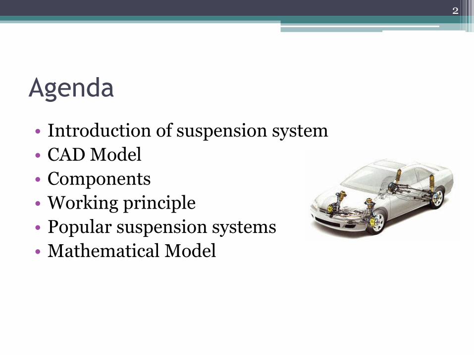
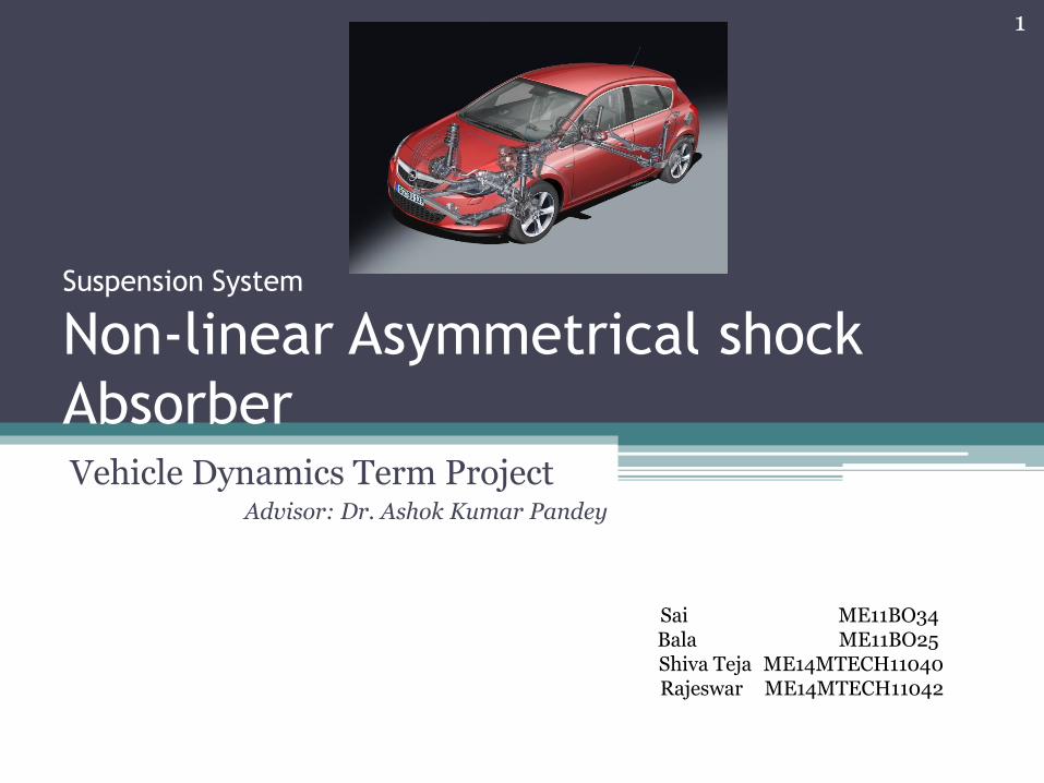
Agenda
• Introduction of suspension system
• CAD Model
• Components
• Working principle
• Popular suspension systems
• Mathematical Model
2
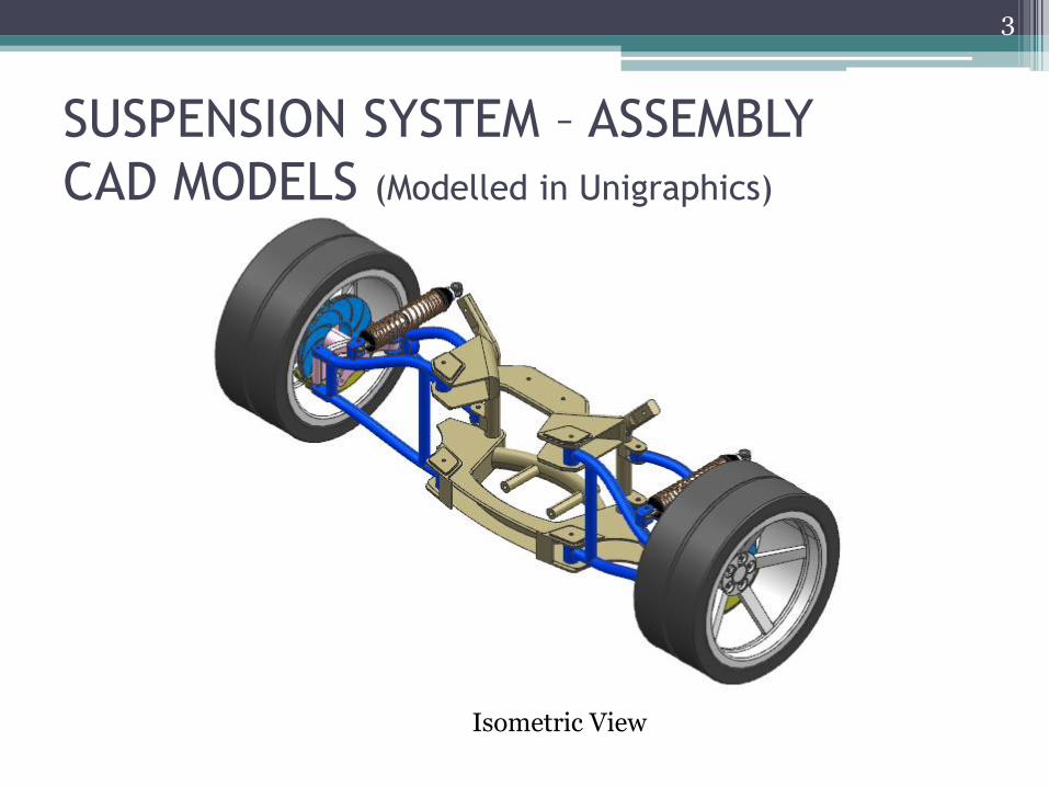
SUSPENSION SYSTEM – ASSEMBLY
CAD MODELS (Modelled in Unigraphics)
3
Isometric View
4
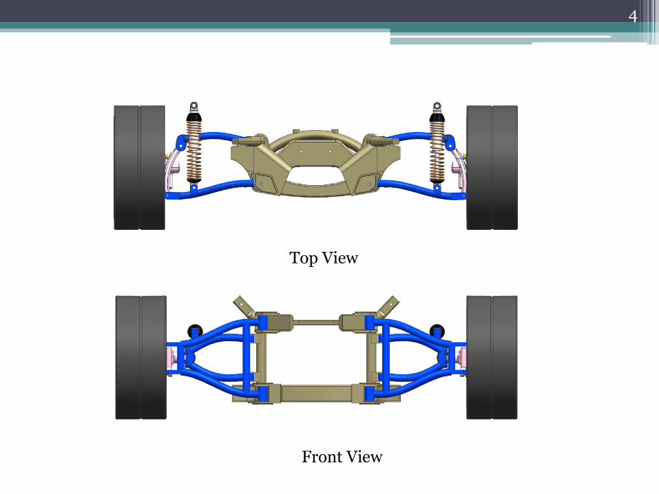
Top View
Front View
5
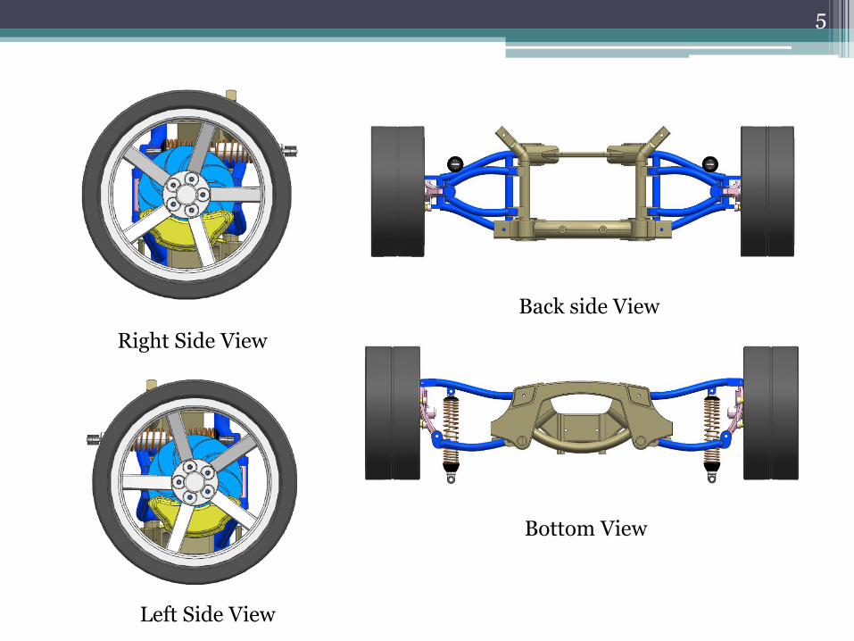
Right Side View
Left Side View
Back side View
Bottom View
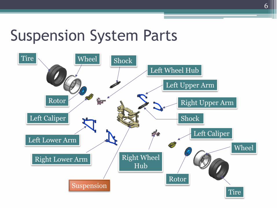
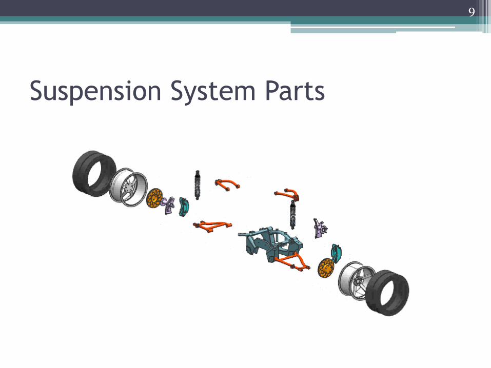
Suspension System Parts
6
Tire Wheel
Rotor
Left Wheel Hub
Left Caliper
Shock
Left Upper Arm
Shock
Right Upper Arm
Left Lower Arm
Right Lower Arm Right Wheel Hub
Left Caliper
Rotor
Wheel
Tire Suspension
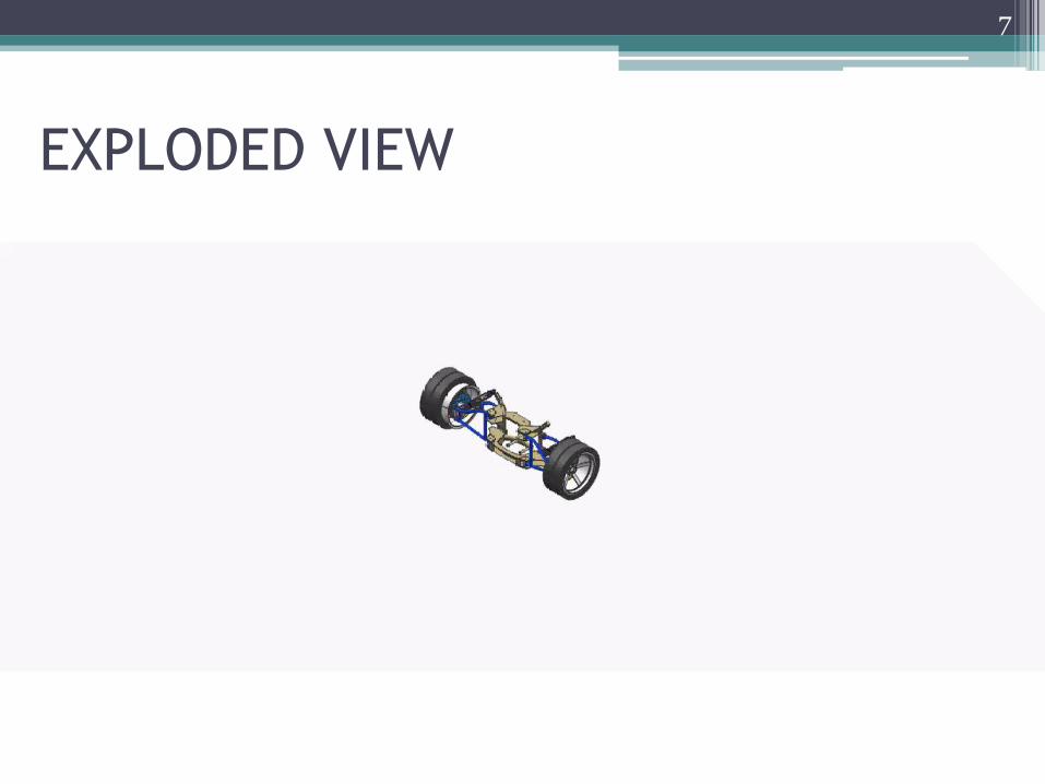
EXPLODED VIEW
7
Functions • Rotor is to dissipate the heat that is generated during braking events. Front rotors
absorb up to 80% of the heat, so they usually are vented with ribs, while rear rotors absorb less and are typically solid discs.
• Caliper integrity is vital to the function of the brake system and can be compromised as a result of exposure to road grit, heat and contaminated brake fluid.
• The wheel hub is fixed rigidly to an upright, telescopic, tubular strut which has its top end anchored to the frame or to a reinforced wing.
• A control arm is a bar that has a pivot at both ends which are arranged to form the letter A. They attach suspension members to the chassis and manage the motion of the wheels so that it synchronizes with that of the body of the car. As a result, you are able to go on joy rides without feeling sick and dizzy, as there is control and smoothness in the movement of the car. Like other body parts, the control arms should also be lubricated at every oil inspection.
Handling and steering could become erratic if the control arms are malfunctioning
and the unsteady movement of your car could take away your riding comfort.
8
Suspension System Parts
9
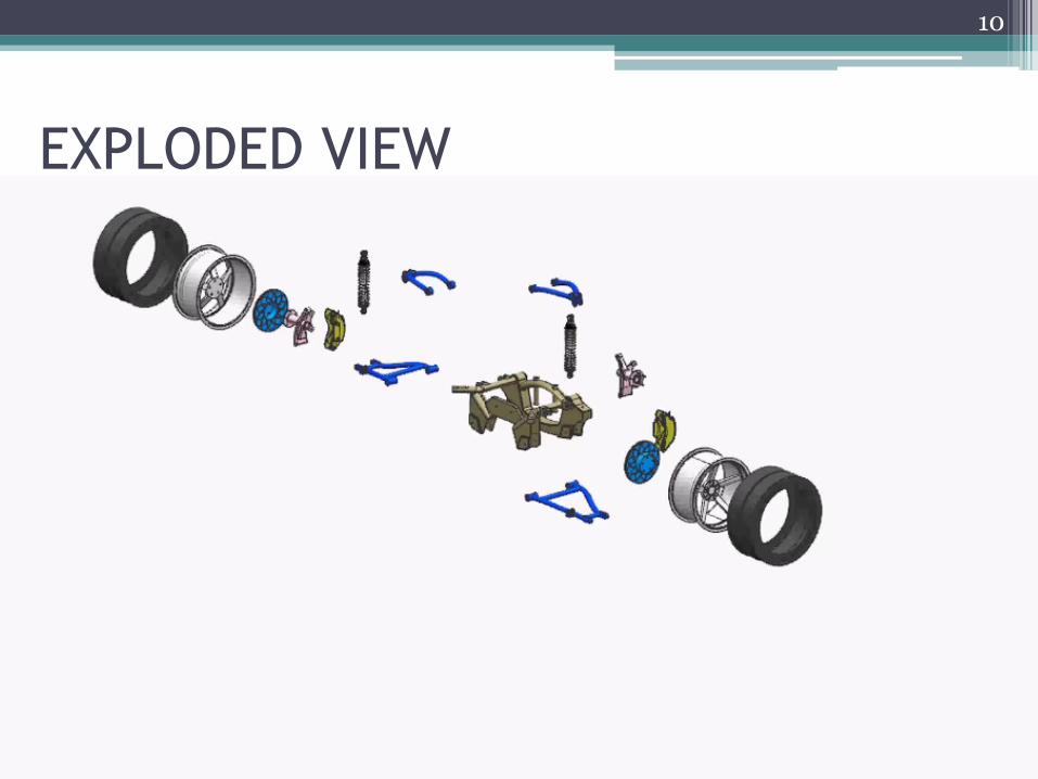
EXPLODED VIEW
10
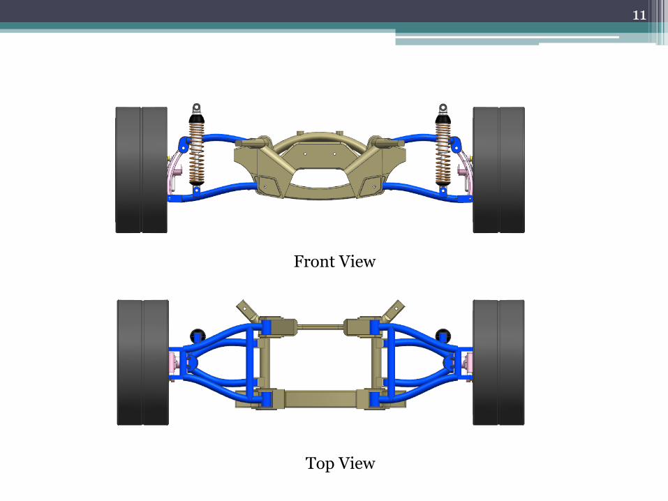
11
Front View
Top View
Suspension system - functions
• to isolate the vehicle from disturbances so that the driver can keep control of the vehicle, without causing discomfort to passengers
• system should minimize vertical motion, as well as pitch and roll movements, as the vehicle passes over an irregular road, performs turning manouvres, and is accelerated or braked heavily.
• Apart from these basic operational aspects, the suspension should also provide a good level of comfort for the passengers, minimizing the movements and accelerations imposed on and perceived by them.
• The level of comfort is increasingly seen as one of the main contributing factors for purchase decision and satisfaction
• The disturbances can be caused by irregularities on the road, or caused by loads inherent of the operation of the vehicle, such as acceleration, braking and turning, as well as aerodynamic loads.
12
Suspension System – Components
• Spring
▫ coil springs
▫ leaf springs
• Damper shock absorber
▫ Need for damper
13
Suspension System – Damper Working
principle
• Hydraulic dampers are prevalent
• During bumps or compression, rod & piston move into the Shock Absorber
• In rebound, or extension, they move out
• For dampening to be effective, resistance is needed in both directions – provided by oil and valves
14
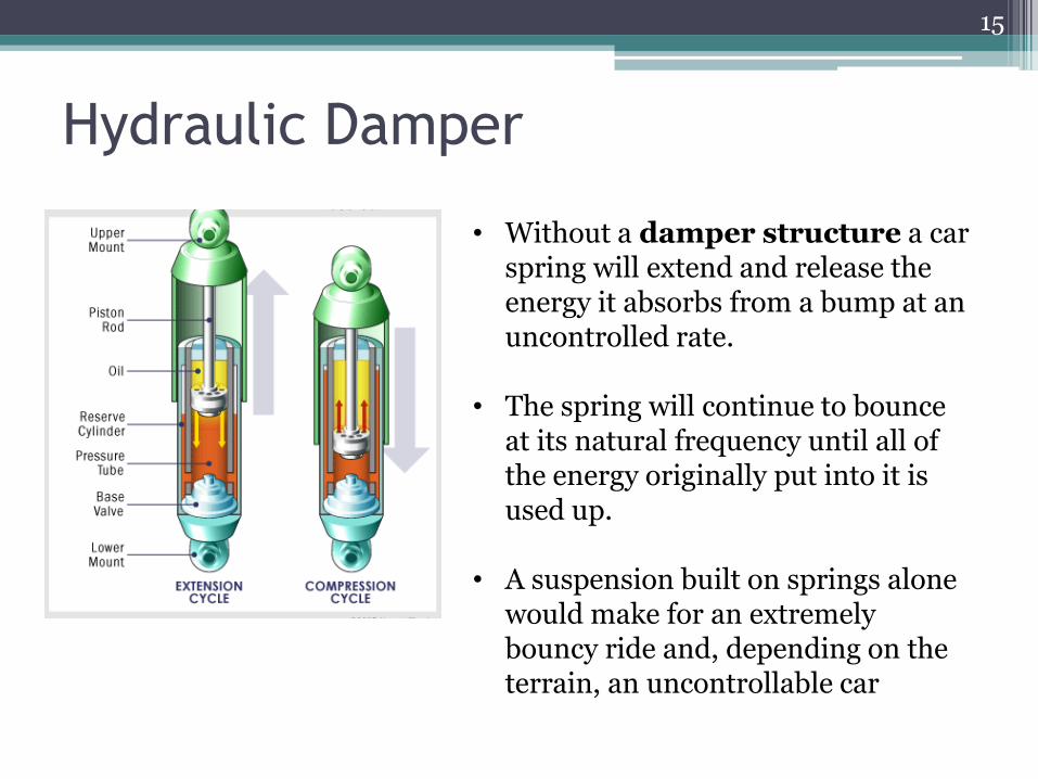
Hydraulic Damper
15
• Without a damper structure a car spring will extend and release the energy it absorbs from a bump at an uncontrolled rate.
• The spring will continue to bounce at its natural frequency until all of the energy originally put into it is used up.
• A suspension built on springs alone would make for an extremely bouncy ride and, depending on the terrain, an uncontrollable car
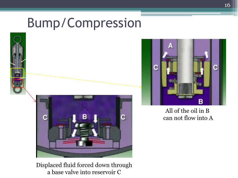
Bump/Compression
All of the oil in B can not flow into A
Displaced fluid forced down through a base valve into reservoir C
16
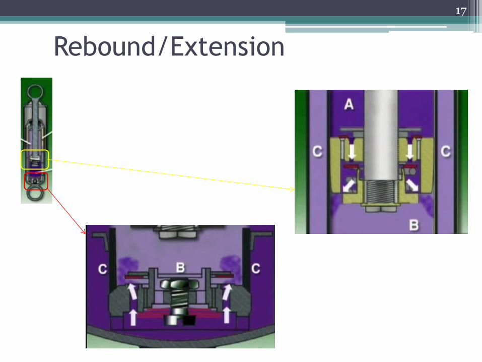
Rebound/Extension
17
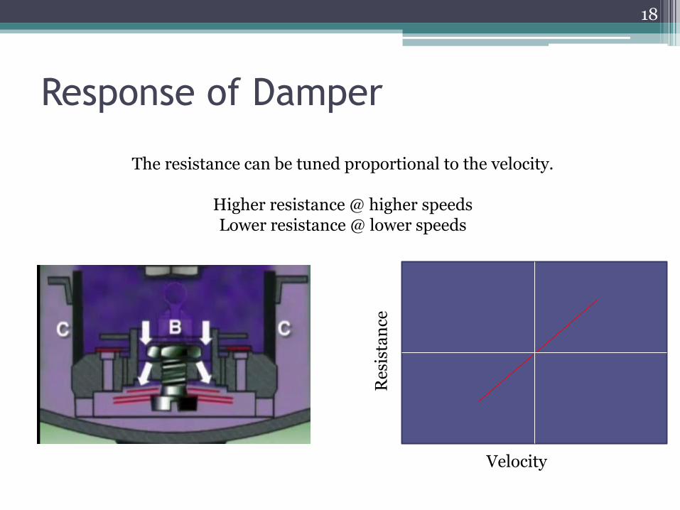
Response of Damper
The resistance can be tuned proportional to the velocity.
Higher resistance @ higher speeds Lower resistance @ lower speeds
Velocity
Res
ista
nce
18
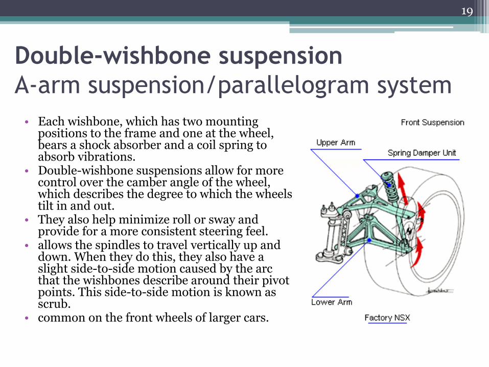
Double-wishbone suspension
A-arm suspension/parallelogram system
• Each wishbone, which has two mounting positions to the frame and one at the wheel, bears a shock absorber and a coil spring to absorb vibrations.
• Double-wishbone suspensions allow for more control over the camber angle of the wheel, which describes the degree to which the wheels tilt in and out.
• They also help minimize roll or sway and provide for a more consistent steering feel.
• allows the spindles to travel vertically up and down. When they do this, they also have a slight side-to-side motion caused by the arc that the wishbones describe around their pivot points. This side-to-side motion is known as scrub.
• common on the front wheels of larger cars.
19
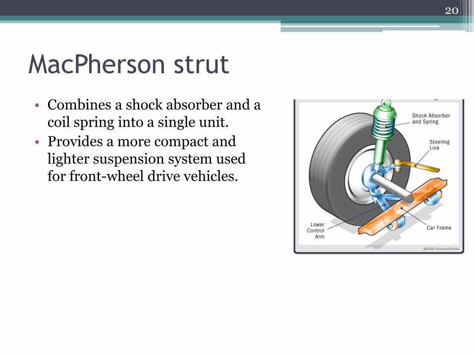
MacPherson strut
• Combines a shock absorber and a coil spring into a single unit.
• Provides a more compact and lighter suspension system used for front-wheel drive vehicles.
20
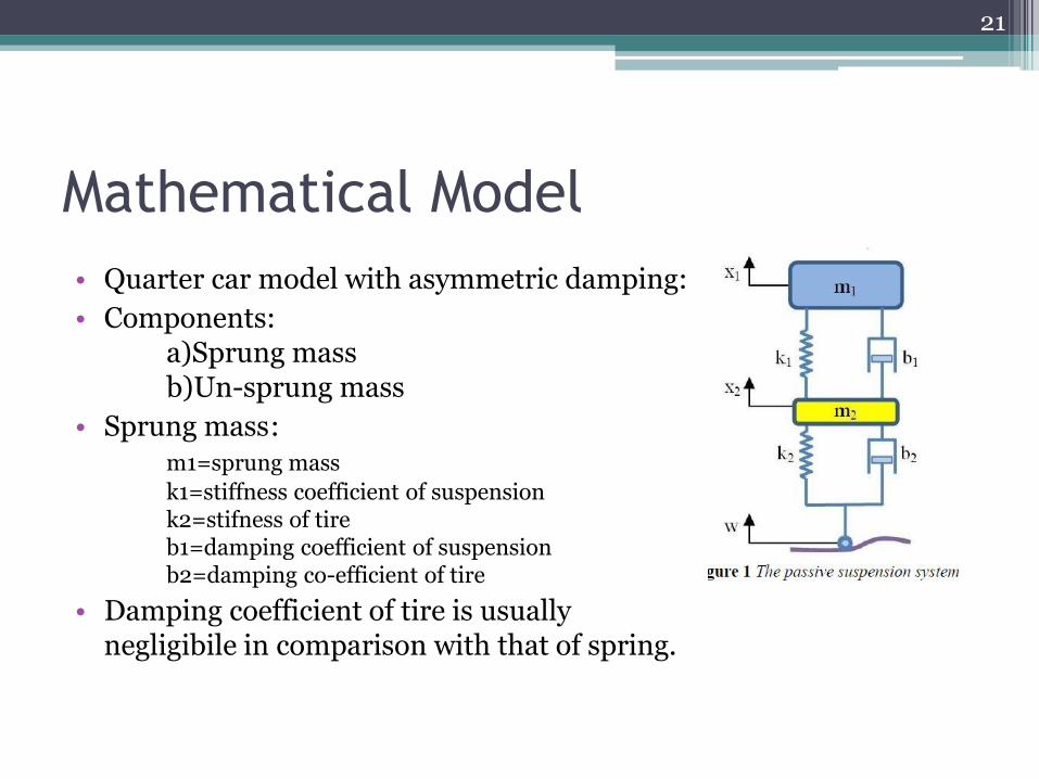
Mathematical Model
• Quarter car model with asymmetric damping:
• Components: a)Sprung mass b)Un-sprung mass
• Sprung mass : m1=sprung mass
k1=stiffness coefficient of suspension k2=stifness of tire b1=damping coefficient of suspension b2=damping co-efficient of tire
• Damping coefficient of tire is usually negligibile in comparison with that of spring.
21
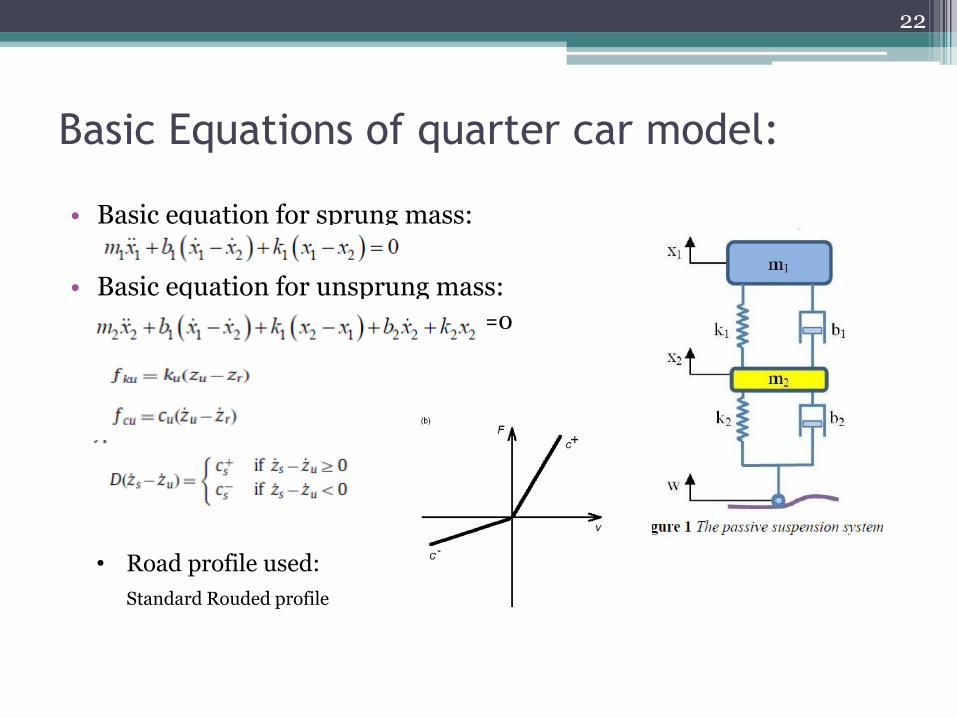
Basic Equations of quarter car model:
• Basic equation for sprung mass:
• Basic equation for unsprung mass:
◦ ==0
22
• Road profile used:
Standard Rouded profile
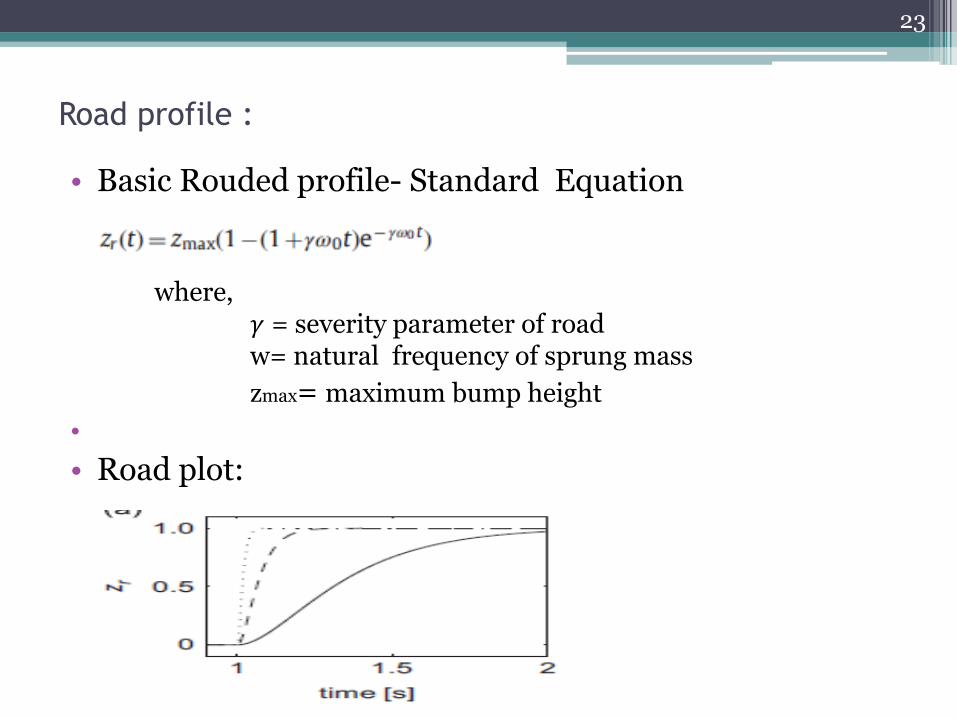
Road profile :
• Basic Rouded profile- Standard Equation where, 𝛾 = severity parameter of road w= natural frequency of sprung mass
zmax= maximum bump height
•
• Road plot:
23
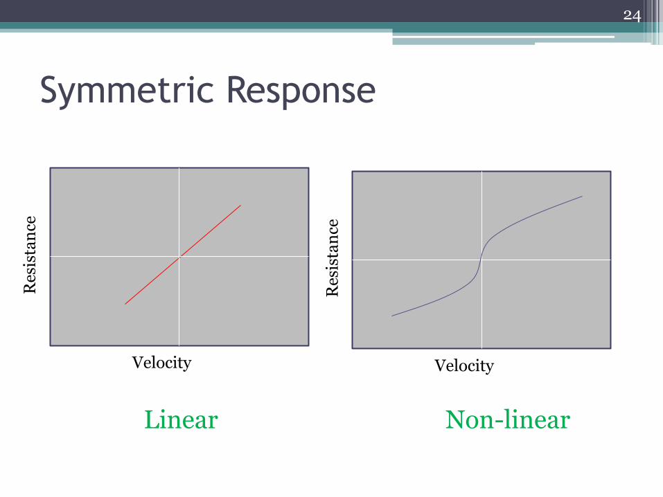
Symmetric Response
Velocity
Res
ista
nce
Velocity
Res
ista
nce
Linear Non-linear
24
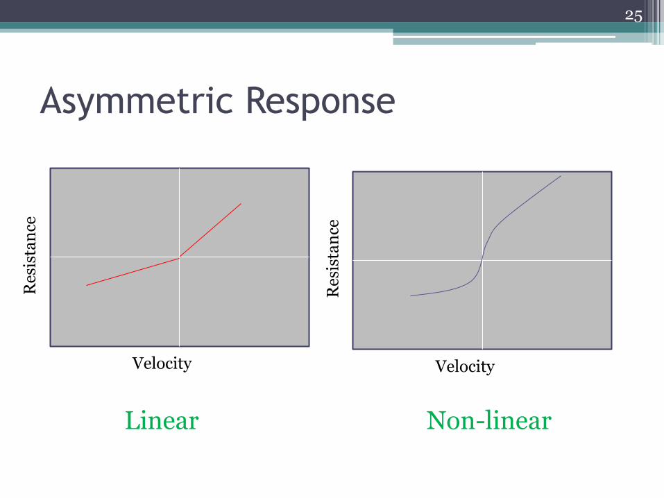
Asymmetric Response
Velocity
Res
ista
nce
Velocity
Res
ista
nce
Linear Non-linear
25
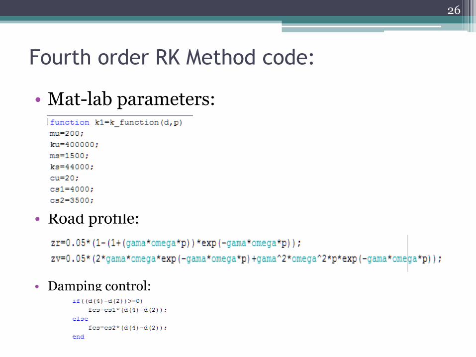
Fourth order RK Method code:
• Mat-lab parameters:
• Road profile:
• Damping control:
26
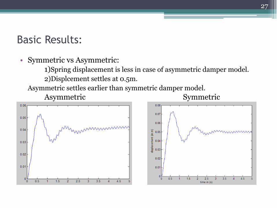
Basic Results:
• Symmetric vs Asymmetric: 1)Spring displacement is less in case of asymmetric damper model.
2)Displcement settles at 0.5m.
Asymmetric settles earlier than symmetric damper model. Asymmetric Symmetric
27
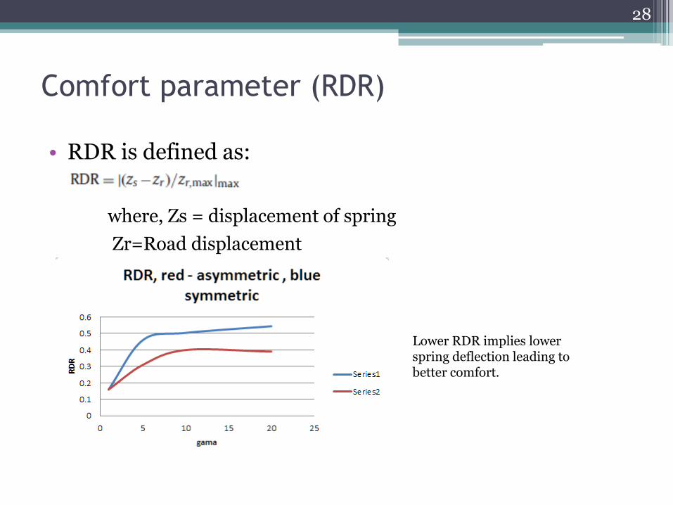
Comfort parameter (RDR)
• RDR is defined as: where, Zs = displacement of spring
Zr=Road displacement
28
Lower RDR implies lower spring deflection leading to better comfort.
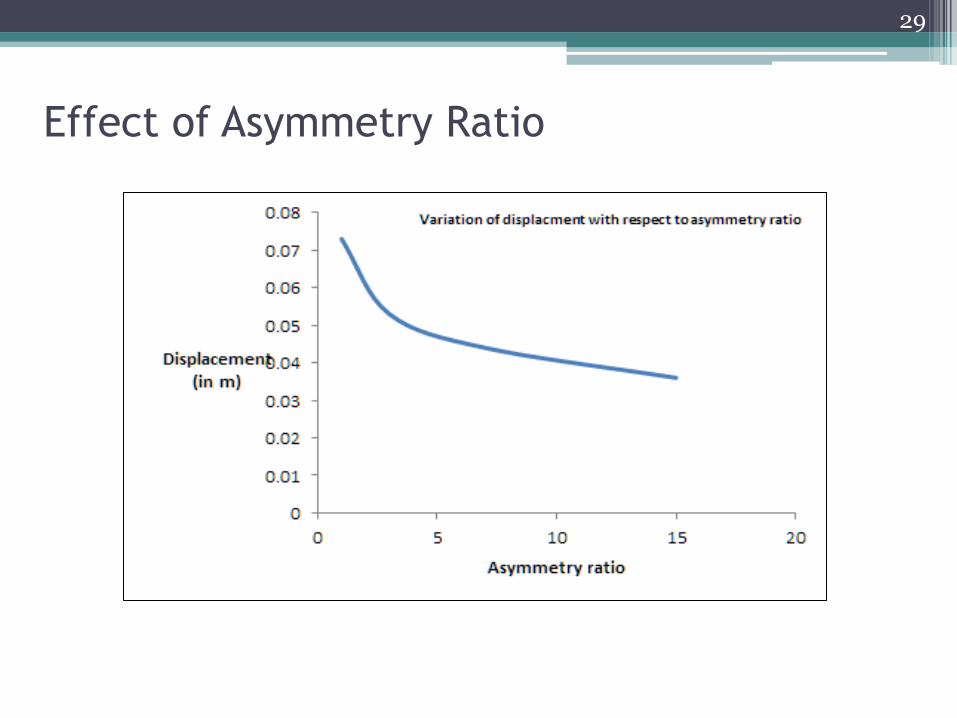
Effect of Asymmetry Ratio
29
Conclusion
• asymmetrical system characteristics, tends to have a smoother and more progressive performance.
• This happens because the damping forces are lower during the first half-cycle, when the impacts occurs.
• This tendency increases with larger severity of impacts, indicating the advantage of the asymmetrical system over the symmetrical one in these conditions which ultimately improves the rider comfort.
30
References
Hydraulic shock absorbers.OTO-HUI.COM https://www.youtube.com/watch?v=vcSH2z706rU&list=PLD41CECBDA5664881&index=37
Chevrolet suspension system in 1938 - Ella73TV https://www.youtube.com/watch?v=1W_J6UhQP6s Use of nonlinear asymmetrical shock-absorber to improve comfort on passenger vehicles M. Silveira , B.R.PontesJr., J.M.Balthazar - Journal of Sound and Vibration http://www.carbibles.com/suspension_bible.html Motor Vehicle Dynamics – Modeling and Simulation – Giancarlo Genta
31