Embed Size (px)
Citation preview

Surveyor Plus
Surveyor LC Pump
Upgrade Guide
60053-97119 Revision B January 2009

© 2009 Thermo Fisher Scientific Inc. All rights reserved.
Xcalibur is a registered trademark and ChromQuest and Surveyor are trademarks of Thermo Fisher Scientific Inc. in the United States.
The following are registered trademarks in the United States and other countries: Windows is a registered trademark of Microsoft Corporation.
Thermo Fisher Scientific Inc. provides this document to its customers with a product purchase to use in the product operation. This document is copyright protected and any reproduction of the whole or any part of this document is strictly prohibited, except with the written authorization of Thermo Fisher Scientific Inc.
The contents of this document are subject to change without notice. All technical information in this document is for reference purposes only. System configurations and specifications in this document supersede all previous information received by the purchaser.
Thermo Fisher Scientific Inc. makes no representations that this document is complete, accurate or error-free and assumes no responsibility and will not be liable for any errors, omissions, damage or loss that might result from any use of this document, even if the information in the document is followed properly.
This document is not part of any sales contract between Thermo Fisher Scientific Inc. and a purchaser. This document shall in no way govern or modify any Terms and Conditions of Sale, which Terms and Conditions of Sale shall govern all conflicting information between the two documents.
Release history: Revision A released in March 2006. Revision B released in January 2009
Software version: ChromQuest 4.0 SP2, ChromQuest 4.1 SP1, or Xcalibur 1.4 SP1
For Research Use Only. Not regulated for medical or veterinary diagnostic use by U.S. Federal Drug Administration or other competent authorities.

WEEE Compliance
This product is required to comply with the European Union’s Waste Electrical & Electronic Equipment (WEEE) Directive 2002/96/EC. It is marked with the following symbol:
Thermo Fisher Scientific has contracted with one or more recycling or disposal companies in each European Union (EU) Member State, and these companies should dispose of or recycle this product. See www.thermo.com/WEEERoHS for further information on Thermo Fisher Scientific’s compliance with these Directives and the recyclers in your country.
WEEE Konformität
Dieses Produkt muss die EU Waste Electrical & Electronic Equipment (WEEE) Richtlinie 2002/96/EC erfüllen. Das Produkt ist durch folgendes Symbol gekennzeichnet:
Thermo Fisher Scientific hat Vereinbarungen mit Verwertungs-/Entsorgungsfirmen in allen EU-Mitgliedsstaaten getroffen, damit dieses Produkt durch diese Firmen wiederverwertet oder entsorgt werden kann. Mehr Information über die Einhaltung dieser Anweisungen durch Thermo Fisher Scientific, über die Verwerter, und weitere Hinweise, die nützlich sind, um die Produkte zu identifizieren, die unter diese RoHS Anweisung fallen, finden sie unter www.thermo.com/WEEERoHS.

Conformité DEEE
Ce produit doit être conforme à la directive européenne (2002/96/EC) des Déchets d'Equipements Electriques et Electroniques (DEEE). Il est marqué par le symbole suivant:
Thermo Fisher Scientific s'est associé avec une ou plusieurs compagnies de recyclage dans chaque état membre de l’union européenne et ce produit devrait être collecté ou recyclé par celles-ci. Davantage d'informations sur la conformité de Thermo Fisher Scientific à ces directives, les recycleurs dans votre pays et les informations sur les produits Thermo Fisher Scientific qui peuvent aider la détection des substances sujettes à la directive RoHS sont disponibles sur www.thermo.com/WEEERoHS.

AVVERTENZA
trumento s de ntes de
al arse y limentacion nto sin sus o remueva
s tarjetas
Shock da folgorazione. L’apparecchio è alimentato da corrente ad alta tensione che puo provocare lesioni fisiche. Prima di effettuare qualsiasi intervento di manutenzione occorre spegnere ed isolare l’apparecchio dalla linea elettrica. Non attivare lo strumento senza lo schermo superiore. Non togliere i coperchi a protezione dalle schede di circuito stampato (PCB).
e contener . Utilice quimicos nos o cipientes y a
Prodotti chimici. Possibile presenza di sostanze chimiche pericolose nell’apparecchio. Indossare dei guanti per maneggiare prodotti chimici tossici, cancerogeni, mutageni, o corrosivi/irritanti. Utilizzare contenitori aprovo e seguire la procedura indicata per lo smaltimento dei residui di olio.
que lop de efectuar
Calore. Attendere che i componenti riscaldati si raffreddino prima di effetturare l’intervento di manutenzione.
ar el
Incendio. Adottare le dovute precauzioni quando si usa il sistema in presenza di gas infiammabili.
icaduras de s que usar teojos tos .
Pericolo per la vista. Gli schizzi di prodotti chimici o delle particelle presenti nell’aria potrebbero causare danni alla vista. Indossare occhiali protettivi quando si maneggiano prodotti chimici o si effettuano interventi di manutenzione sull’apparecchio.
e existe un gorias én se utiliza l usuario a n este
Pericolo generico. Pericolo non compreso tra le precedenti categorie. Questo simbolo è utilizzato inoltre sull’apparecchio per segnalare all’utente di consultare le istruzioni descritte nel presente manuale.
de un tes de o con la local para r Scientific
Quando e in dubbio la misura di sicurezza per una procedura, prima di continuare, si prega di mettersi in contatto con il Servizio di Assistenza Tecnica locale per i prodotti di Thermo Fisher Scientific San Jose.
CAUTION Symbol CAUTION VORSICHT ATTENTION PRECAUCION
Electric Shock: This instrument uses high voltages that can cause personal injury. Before servicing, shut down the instrument and disconnect the instrument from line power. Keep the top cover on while operating the instrument. Do not remove protective covers from PCBs.
Elektroschock: In diesem Gerät werden Hochspannungen verwendet, die Verletzungen verursachen können. Vor Wartungsarbeiten muß das Gerät abgeschaltet und vom Netz getrennt werden. Betreiben Sie Wartungsarbeiten nicht mit abgenommenem Deckel. Nehmen Sie die Schutzabdeckung von Leiterplatten nicht ab.
Choc électrique: L’instrument utilise des tensions capables d’infliger des blessures corprelles. L’instrument doit être arrêté et débranché de la source de courant avant tout intervention. Ne pas utiliser l’instrument sans son couvercle. Ne pas elensver les étuis protecteurs des cartes de circuits imprimés.
Descarga eléctrica: Este insutiliza altas tensiones, capaceproducir lesiones personales. Adar servicio de mantenimientoinstrumento, éste debera apagdesconectarse de la línea de aeléctrica. No opere el instrumecubiertas exteriores quitadas. Nlas cubiertas protectoras de lade circuito impreso.
Chemical: This instrument might contain hazardous chemicals. Wear gloves when handling toxic, carcinogenic, mutagenic, or corrosive or irritant chemicals. Use approved containers and proper procedures to dispose waste oil.
Chemikalien: Dieses Gerät kann gefährliche Chemikalien enthalten. Tragen Sie Schutzhandschuhe beim Umgang mit toxischen, karzinogenen, mutagenen oder ätzenden/reizenden Chemikalien. Entsorgen Sie verbrauchtes Öl entsprechend den Vorschriften in den vorgeschriebenen Behältern.
Chimique: Des produits chemiques dangereux peuven se trouver dans l’instrument. Proted dos gants pour manipuler tous produits chemiques toxiques, cancérigènes, mutagènes, ou corrosifs/irritants. Utiliser des récipients et des procédures homologuées pour se débarrasser des déchets d’huile.
Química: El instrumento puedproductos quimicos peligrososguantes al manejar productos tóxicos, carcinogenos, mutagecorrosivos/irritantes. Utilice reprocedimientos aprobados pardeshacerse del aceite usado.
Heat: Before servicing the instrument, allow any heated components to cool.
Hitze: Warten Sie erhitzte Komponenten erst nachdem diese sich abgekühlt haben.
Haute Temperature: Permettre aux composants chauffés de refroidir avant tout intervention.
Altas temperaturas: Permitacomponentes se enfríen, ante servicio de mantenimiento.
Fire: Use care when operating the system in the presence of flammable gases.
Feuer: Beachten Sie die einschlägigen VorsichtsmaBnahmen, wenn Sie das System in Gegenwart von entzündbaren Gasen betreiben.
Incendie: Agir avec précaution lors de l’utilisation du système en présence de gaz inflammables.
Fuego: Tenga cuidado al opersistema en presencia de gasesinflamables.
Eye Hazard: Eye damage could occur from splattered chemicals or flying particles. Wear safety glasses when handling chemicals or servicing the instrument.
Verletzungsgefahr der Augen: Verspritzte Chemikalien oder kleine Partikel können Augenverletzungen verursachen. Tragen Sie beim Umgang mit Chemikalien oder bei der Wartung des Gerätes eine Schutzbrille.
Danger pour les yeux: Dex projections chimiques, liquides, ou solides peuvent être dangereuses pour les yeux. Porter des lunettes de protection lors de toute manipulationde produit chimique ou pour toute intervention sur l’instrument.
Peligro par los ojos: Las salproductos químicos o particulasalten bruscamente pueden calesiones en los ojos. Utilice anprotectores al mnipular producquímicos o al darle servicio demantenimiento al instrumento
General Hazard: A hazard is present that is not included in the above categories. Also, this symbol appears on the instrument to refer the user to instructions in this manual.
Allgemeine Gefahr: Es besteht eine weitere Gefahr, die nicht in den vorstehenden Kategorien beschrieben ist. Dieses Symbol wird im Handbuch auBerdem dazu verwendet, um den Benutzer auf Anweisungen hinzuweisen.
Danger général: Indique la présence d;un risque n’appartenant pas aux catégories citées plus haut. Ce symbole figure également sur l’instrument pour renvoyer l’utilisateur aux instructions du présent manuel.
Peligro general: Significa qupeligro no incluido en las cateanteriores. Este simbolo tambien el instrumento par referir alas instrucciones contenidas emanual.
When the safety of a procedure is questionable, contact your local Technical Support organization for Thermo Fisher Scientific San Jose Products.
Wenn Sie sich über die Sicherheit eines Verfahrens im unklaren sind, setzen Sie sich, bevor Sie fortfahren, mit Ihrer lokalen technischen Unterstützungsorganisation für Thermo Fisher Scientific San Jose Produkte in Verbindung.
Si la sûreté d’un procédure est incertaine, avant de continuer, contacter le plus proche Service Clientèle pour les produits de Thermo Fisher Scientific San Jose.
Cuando la certidumbre acerca procedimiento sea dudosa, anproseguir, pongase en contactOficina de Asistencia Tecnica los productos de Thermo FisheSan Jose.

CAUTION Symbol CAUTION
Electric Shock: This instrument uses high voltages that can cause personal injury. Before servicing, shut down the instrument and disconnect the instrument from line power. Keep the top cover on while operating the instrument. Do not remove protective covers from PCBs.
Chemical: This instrument might contain hazardous chemicals. Wear gloves when handling toxic, carcinogenic, mutagenic, or corrosive or irritant chemicals. Use approved containers and proper procedures to dispose waste oil.
Heat: Before servicing the instrument, allow any heated components to cool.
Fire: Use care when operating the system in the presence of flammable gases.
Eye Hazard: Eye damage could occur from splattered chemicals or flying particles. Wear safety glasses when handling chemicals or servicing the instrument.
General Hazard: A hazard is present that is not included in the above categories. Also, this symbol appears on the instrument to refer the user to instructions in this manual.
When the safety of a procedure is questionable, contact your local Technical Support organization for Thermo Fisher Scientific San Jose Products.

C
Contents
Preface . . . . . . . . . . . . . . . . . . . . . . . . . . . . . . . . . . . . . . . . . . . . . . . . . . . . . . . . . . . . . . ixRelated Documentation . . . . . . . . . . . . . . . . . . . . . . . . . . . . . . . . . . . . . . . . . . .ixSafety and Special Notices . . . . . . . . . . . . . . . . . . . . . . . . . . . . . . . . . . . . . . . . .ixContacting Us . . . . . . . . . . . . . . . . . . . . . . . . . . . . . . . . . . . . . . . . . . . . . . . . . . x
Chapter 1 Upgrade Kit Contents . . . . . . . . . . . . . . . . . . . . . . . . . . . . . . . . . . . . . . . . . . . . . . . . . . .1
Chapter 2 Installing the Interconnect Printed Circuit Board. . . . . . . . . . . . . . . . . . . . . . . . . . .3
Chapter 3 Downloading Firmware . . . . . . . . . . . . . . . . . . . . . . . . . . . . . . . . . . . . . . . . . . . . . . . . .7Step 1: Preparing the LC Pump for a Firmware Download . . . . . . . . . . . . . . . . . 8Step 2: Downloading the Instrument Control Firmware . . . . . . . . . . . . . . . . . . . 9Step 3: Downloading the Communication Firmware . . . . . . . . . . . . . . . . . . . . 14Step 4: Returning the Pump to Normal Operation . . . . . . . . . . . . . . . . . . . . . . 19
Chapter 4 Upgrading the Chromatography Data System . . . . . . . . . . . . . . . . . . . . . . . . . . . . .21
Chapter 5 Adding the Surveyor LC Pump Plus Labels. . . . . . . . . . . . . . . . . . . . . . . . . . . . . . . .23
Chapter 6 Configuring the Surveyor Plus System . . . . . . . . . . . . . . . . . . . . . . . . . . . . . . . . . . .25Configuring the Instrument in ChromQuest. . . . . . . . . . . . . . . . . . . . . . . . . . . 25
Configuring the Surveyor LC Pump Plus . . . . . . . . . . . . . . . . . . . . . . . . . . . 25Configuring the Signal Polarities for the Surveyor AS . . . . . . . . . . . . . . . . . . 30
Configuring the Instrument in Xcalibur . . . . . . . . . . . . . . . . . . . . . . . . . . . . . . 31Configuring the LC Pump . . . . . . . . . . . . . . . . . . . . . . . . . . . . . . . . . . . . . . 31Configuring the Signal Polarities for the Surveyor AS . . . . . . . . . . . . . . . . . . 32
Index . . . . . . . . . . . . . . . . . . . . . . . . . . . . . . . . . . . . . . . . . . . . . . . . . . . . . . . . . . . . . . . .35
Thermo Scientific Surveyor LC Pump Upgrade Guide vii


P
Preface
This installation guide describes how to upgrade the Surveyor™ LC Pump to a Surveyor LC Pump Plus.
To increase the retention time reproducibility of the LC system, the upgraded LC pump issues two output signals to the autosampler at the start of a run. The LC pump issues the first output signal when it senses a stable backpressure. It issues the second output signal when its cams return to the start position. The autosampler waits for these two signals before it performs an injection.
Related DocumentationIn addition to this guide, Thermo Fisher Scientific provides the following documents for the Surveyor LC Pump Plus:
• Surveyor LC Pump Plus Hardware Manual
• Surveyor Plus Getting Started with ChromQuest Guide
• Surveyor Plus Getting Started with Xcalibur Guide
Safety and Special NoticesMake sure you follow the precautionary statements presented in this guide. The safety and other special notices appear in boxes.
Safety and special notices include the following:
CAUTION Highlights hazards to humans, property, or the environment. Each CAUTION notice is accompanied by an appropriate CAUTION symbol.
IMPORTANT Highlights information necessary to prevent damage to software, loss of data, or invalid test results; or might contain information that is critical for optimal performance of the system.
Thermo Scientific Surveyor LC Pump Upgrade Guide ix
Preface
x
Contacting UsThere are several ways to contact Thermo Fisher Scientific for the information you need.
To contact Technical Support
Find software updates and utilities to download at mssupport.thermo.com.
To contact Customer Service for ordering information
To copy manuals from the Internet
Go to mssupport.thermo.com and click Customer Manuals in the left margin of the window.
To suggest changes to documentation or to Help
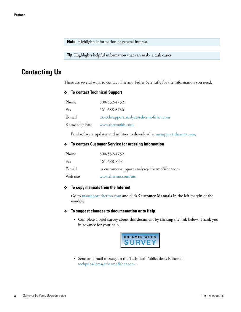
• Complete a brief survey about this document by clicking the link below. Thank you in advance for your help.
• Send an e-mail message to the Technical Publications Editor at [email protected].
Note Highlights information of general interest.
Tip Highlights helpful information that can make a task easier.
Phone 800-532-4752
Fax 561-688-8736
E-mail [email protected]
Knowledge base www.thermokb.com
Phone 800-532-4752
Fax 561-688-8731
E-mail [email protected]
Web site www.thermo.com/ms
Surveyor LC Pump Upgrade Guide Thermo Scientific

1
Upgrade Kit Contents
Table 1 lists the items supplied in the Surveyor LC Pump upgrade kit (P/N 60053-62045). In addition to these items, you must also have the items listed in Table 2 on page 7 to upgrade the communication firmware. The items listed in Table 2 are included in the Surveyor LC Pump accessory kit.
To upgrade the Surveyor LC Pump to a Surveyor LC Pump Plus, do the following:
1. Install the new interconnect PCB by following the instructions in Chapter 2, “Installing the Interconnect Printed Circuit Board.”
2. Download the new CPU and communication firmware by following the instructions in Chapter 3, “Downloading Firmware.”
3. Install the service pack for your chromatography data system by following the instructions in Chapter 4, “Upgrading the Chromatography Data System.”
4. Attach the back panel labels for the Surveyor LC Pump Plus by following the instructions in Chapter 5, “Adding the Surveyor LC Pump Plus Labels.”
5. Configure the autosampler to recognize the output signals from the upgraded LC pump by following the instructions in Chapter 6, “Configuring the Surveyor Plus System.”
Table 1. Parts list for the Surveyor LC Pump Upgrade kit
Description Part Number
LC Pump Plus interconnect PCB assembly 00950-01-00022
ChromQuest 4.0 SP1 software CD-ROM CHROM-98002
ChromQuest 4.1 SP1 software CD-ROM CHROM-98003
Label set, Surveyor LC Pump Plus 60053-50105
Label, Surveyor LC Pump Plus upgrade 60053-50110
Xcalibur Surveyor LC Pump 1.4 SP1 software XCALI-64069
Manual CD-ROM 60053-64000
Thermo Scientific Surveyor LC Pump Upgrade Guide 1


2
Installing the Interconnect Printed Circuit Board
The new interconnect PCB contains the circuitry that enables the Pump RDY output signal and the INJ HOLD output signal, generated from pins 5 and 6, respectively, on the back panel of the LC pump. See Figure 24 on page 23.
To install the new PCB
1. Turn off the power to the Surveyor LC Pump by pressing the power button below the left door of the pump, and then unplug the pump from line power.
2. Gain access to the interconnect PCB as follows:
a. Detach the LED cable from the inner right-door of the pump.
Figure 1. Detaching the LED cable
b. Pull the drainage funnel forward off the housing of the pump. See Figure 2.
c. Use a #2 Phillips screwdriver to remove the four screws that secure the chassis of the pump to its housing. See Figure 2.
CAUTION Because the Surveyor LC Pump contains a high voltage supply, you must turn off the power to the pump and unplug it from line power before you pull the chassis out of the housing.
LED cable
Thermo Scientific Surveyor LC Pump Upgrade Guide 3

2 Installing the Interconnect Printed Circuit Board
4
Figure 2. View of the LC pump, showing the chassis pulled out of the housing
d. Pull the chassis forward out of the housing. See Figure 3.
Figure 3. View of the LC pump without its housing
3. Remove the interconnect PCB as follows:
a. Detach the eight cables connected to the interconnect PCB. See Figure 4.
Screws
Drainage funnel
Screws
InterconnectPCB
CAUTION Because it is easy to drop the small screws that secure the interconnect PCB to the chassis, take care as you remove them.
Surveyor LC Pump Upgrade Guide Thermo Scientific

2 Installing the Interconnect Printed Circuit Board
T
b. Using a #1 Phillips screwdriver, carefully remove the four screws that secure the interconnect PCB to the chassis. See Figure 4.
Figure 4. View of the interconnect PCB, showing the cable connections
4. Install the new interconnect PCB as follows:
a. Use the screws you removed in step 3b to secure the new interconnect PCB to the chassis of the pump.
b. Reattach the eight cables shown in Figure 4.
5. Push the chassis back into the housing. Then secure it to the housing with the four screws you removed in step c on page 3.
6. Reconnect the LED cable to the inner right-door of the pump. See Figure 1 on page 3.
7. Reinstall the drainage funnel. See Figure 2 on page 4.
8. Reconnect the LC pump to line power, but do not turn the pump on.
Screws (4x)
hermo Scientific Surveyor LC Pump Upgrade Guide 5


3
Downloading Firmware
Table 2 lists the hardware that you must have to download firmware to the CPU board.
To download the instrument control firmware and the communication firmware, perform these steps:
• Step 1: Preparing the LC Pump for a Firmware Download
• Step 2: Downloading the Instrument Control Firmware
• Step 3: Downloading the Communication Firmware
• Step 4: Returning the Pump to Normal Operation
Table 2. Hardware required to download firmware to the CPU board
Figure Description Part Number
8-pin, minicombicon connector 00004-02511
RJ45 to DB9 cable adapter A3538-010
Serial communication cable 60053-63003
Thermo Scientific Surveyor LC Pump Upgrade Guide 7

3 Downloading FirmwareStep 1: Preparing the LC Pump for a Firmware Download
8
Step 1: Preparing the LC Pump for a Firmware DownloadTo prepare the LC pump for a firmware download
1. Ensure that the LC Pump is turned off.
2. Use a flathead screwdriver to set the rotary switches located on the back panel of the LC pump to 00. See Figure 5.
Figure 5. View of rotary switches, showing the Unit ID set to 00
3. Plug an 8-pin, 3.81 mm pitch, minicombicon connector (P/N 00004-02511) into positions 9 through 16 on the back panel of the LC pump. Then create a jumper across pins 9 and 15 with a piece of wire, such as a paperclip. See Figure 6.
Figure 6. View of the LC pump back panel, showing a jumper between pins 9 and 15
4. Plug an RJ-45 to DB9 adapter (P/N A3538-010) into a COM port on your computer and record the port number.
5. Using a serial communication cable (P/N 60053-63003), connect the COM port on the back panel of the computer to the RS232 connection located on the back panel of the LC pump. See Figure 7.
1
2 3
45
6
78
90
1
2 3
45
6
78
90
UNIT IDNCFW DOW
NLOAD
TF1
PRESSURE -PRESSURE+
+5V @ 15Om
AGNDPUMP ONGNDNCNCPROG. START
+5V @ 150m
AGND
NC TF2
RS232 ENET
Minicombicon plug
Shorting wire[connecting pin 9 (GND) to pin 15 (FW Download)]
Surveyor LC Pump Upgrade Guide Thermo Scientific

3 Downloading FirmwareStep 2: Downloading the Instrument Control Firmware
Figure 7. Back panel connections between the computer and the Surveyor LC Pump
6. Turn on the power to the LC pump.
7. Verify that the Power LED is green, the Comm LED is flashing amber, and the other two LEDs are not illuminated. See Figure 8.
Figure 8. Surveyor LC Pump LEDs
Step 2: Downloading the Instrument Control Firmware The ChromQuest software CD-ROM contains the Update.exe utility that allows you to download the instrument control firmware.
To download the control firmware
1. Use Windows™ Explorer to locate the Update.exe utility on the ChromQuest software CD-ROM. As Figure 9 shows, the Update.exe utility and the firmware file (*lcb) are located in the following folder:
CD-ROM drive:\ChromQuest\Firmware\60053-98020 LPump v2.00 \LPump Control Firmware
UNIT IDNCFW DOW
NLOAD
NC PRESSURE -PRESSURE+
+5V @ 15Om
AGNDPUMP ONGND
+5V @ 150m
AGND
NC NC
RS232 ENET1 2 3 4 5 6 7 8 9 10 11 12 13 14 15 16
NC
Ethernet port
Back panel of Surveyor LC PumpComputer
Serial port with DB9 to RJ45 adapter
Serial communication cable
Ethernet switch
Ethernetport
Power Comm Run Degas
Thermo Scientific Surveyor LC Pump Upgrade Guide 9

3 Downloading FirmwareStep 2: Downloading the Instrument Control Firmware
10
Figure 9. View of the contents of the LPump Control Firmware folder
2. Double-click the Update.exe icon to start the utility.
The Update Windows Application – Update dialog box appears. See Figure 10.
Figure 10. Update Windows Application – Update dialog box
3. Set up the appropriate communication settings as follows:
a. Choose Communication > Settings to open the COM Port Setting dialog box. See Figure 11.
Surveyor LC Pump Upgrade Guide Thermo Scientific

3 Downloading FirmwareStep 2: Downloading the Instrument Control Firmware
Figure 11. COM Port Setting dialog box
b. In the COM Port Setting dialog box, do the following:
• In the Port list, select the COM port that the pump is connected to.
• In the Baud Rate list, select 19200 bps.
• In the Time out (ms) box, type 2000.
• In the Retry count box, type 3.
c. Click OK to close the COM Port Settings dialog box.
4. In the Update Windows Application – Update dialog box, click Connect.
The ROM Program Update Utility dialog box appears. See Figure 12.
Figure 12. ROM Program Update Utility dialog box
5. In the ROM Program Update Utility dialog box, click OK to return to the Update Windows Application – Update dialog box.
The Current box displays the current firmware version. See Figure 13.
Thermo Scientific Surveyor LC Pump Upgrade Guide 11

3 Downloading FirmwareStep 2: Downloading the Instrument Control Firmware
12
Figure 13. Update Windows Application – Update dialog box, showing the current firmware version
6. In the Update Windows Application – Update dialog box, choose File > Change Directory to open the Change Directory dialog box.
7. In the Change Directory dialog box, change the directory to the LPump Control Firmware folder as follows (see Figure 14):
a. Double-click [chromq’’’c].
b. Double-click [firmware].
c. Double-click [60053-’’’7.00].
d. Double-click [lcpump’’’2].
e. Click OK.
Figure 14. Change Directory dialog box
The Update Windows Application – Update dialog box appears with the name of the firmware file in the Files box. See Figure 15.
Surveyor LC Pump Upgrade Guide Thermo Scientific

3 Downloading FirmwareStep 2: Downloading the Instrument Control Firmware
Figure 15. Update Windows Application – Update dialog box, showing the new file name in the Files box
8. In the Update Windows Application – Update dialog box, click the file name to highlight it as Figure 16 shows. Then click Update.
Figure 16. Update Windows Application – Update dialog box, showing the new file name highlighted
The utility displays the status of the download activity at the bottom of the dialog box. When the download is complete, the message shown in Figure 17 appears.
Figure 17. ROM Program Update Utility
Thermo Scientific Surveyor LC Pump Upgrade Guide 13

3 Downloading FirmwareStep 3: Downloading the Communication Firmware
14
9. Click OK to close the ROM Program Update Utility dialog box and return to the Update Windows Application dialog box.
The Current read-only box displays the current firmware version. See Figure 18.
Figure 18. Update Windows Application – Update dialog box, showing the updated firmware listed in the Current box
10. After verifying a successful firmware download, click Exit to close the program.
Step 3: Downloading the Communication FirmwareThe Surveyor Firmware Upgrade Utility allows you to download firmware files to the ethernet converter board of the Surveyor instrument modules. Communication firmware upgrade files have a .bin extension.
The installer for the Xcalibur data system automatically installs the firmware files and the Surveyor Firmware Upgrade utility to your computer during the installation of the data system. These files can be found in the following folder: [drive]:\Xcalibur\system\Surveyor Firmware. See Figure 19.
Surveyor LC Pump Upgrade Guide Thermo Scientific

3 Downloading FirmwareStep 3: Downloading the Communication Firmware
Figure 19. Surveyor Firmware folder installed with Xcalibur
The installer for the ChromQuest data system does not install the firmware files and the Surveyor Firmware Upgrade Utility to your computer during the installation of the data system. These files reside on the ChromQuest CD, and you must copy them to an appropriate folder on your computer.
To download the communication firmware
1. Do one of the following:
• For the Xcalibur data system, go to step 3.
• For the ChromQuest data system, go to step 2.
2. Install the firmware files onto your computer as follows:
a. Insert the ChromQuest CD into your CD-ROM drive.
b. From the Windows desktop, double-click My Computer.
c. Right-click the CQ icon to open the shortcut menu.
d. Choose Explore from the shortcut menu to access the contents of the CD.
e. Copy the contents of the Firmware folder to your ChromQuest directory.
The Firmware folder contains folders for all the Surveyor instruments and the Surveyor Firmware Upgrade Utility. See Figure 20.
Thermo Scientific Surveyor LC Pump Upgrade Guide 15

3 Downloading FirmwareStep 3: Downloading the Communication Firmware
16
Figure 20. CD Drive:\ChromQuest\Firmware folder
3. Before you start the Surveyor Firmware Upgrade Utility application, ensure that the LC pump is connected to the data system computer with the standard Ethernet connection. See the Ethernet connections in Figure 7 on page 9.
4. Start the Surveyor Firmware Upgrade Utility by double-clicking the Surveyor Firmware Upgrade Utility application.
The Surveyor Firmware Upgrade Utility window appears. See Figure 21.
Surveyor LC Pump Upgrade Guide Thermo Scientific

3 Downloading FirmwareStep 3: Downloading the Communication Firmware
Figure 21. Surveyor Firmware Upgrade Utility
5. In the Surveyor Firmware Upgrade Utility window, initiate communication between the utility and the Surveyor LC Pump Plus.
a. Under Device Type, select the Surveyor LC Pump option (see Figure 21).
b. Click Connect.
The status display at the bottom of the Surveyor Firmware Upgrade Utility window indicates that a connection has been made.
6. In the Surveyor Firmware Upgrade Utility window, select the firmware files (see Figure 22) for the Surveyor LC Pump Plus as follows:
a. Under File Names, click Browse to the right of the ROM box to select the ROM file (“ROM*.bin”).
The filename appears in the ROM box.
b. Under File Names, click Browse to the right of the App1 box to select the APP1 file (“LC Pump*.bin”).
CAUTION Do not interrupt the firmware download process. Do not turn off the power to the LC pump or close the Surveyor Firmware Upgrade Utility after you click Connect and establish communication. If you turn off the power to the LC pump or close the utility at this point, you will have to return the pump to the factory for reprogramming.
Thermo Scientific Surveyor LC Pump Upgrade Guide 17

3 Downloading FirmwareStep 3: Downloading the Communication Firmware
18
The filename appears in the App1 box.
Figure 22. Surveyor Firmware Upgrade Utility, showing selection of Surveyor LC Pump Plus firmware files
7. After you select the appropriate firmware files, click Download. Then wait for the download to finish.
The utility notifies you when the download is complete.
8. Click Disconnect to terminate the connection with the Surveyor LC Pump Plus, and then close the Surveyor Firmware Upgrade Utility.
IMPORTANT If you do not select both a ROM file and an APP1 file, the Surveyor LC Pump will not work properly.
Note Now that you have terminated the connection, it is safe to turn off the power to the LC pump.
Surveyor LC Pump Upgrade Guide Thermo Scientific

3 Downloading FirmwareStep 4: Returning the Pump to Normal Operation
Step 4: Returning the Pump to Normal OperationTo return the LC pump to its operational configuration
1. Turn off the power to the LC pump.
2. Disconnect the serial cable from the back of the LC pump and the computer.
3. Disconnect the adapter from the computer.
4. Remove the minicombicon connector from the back panel of the LC pump.
5. Use a small flathead screwdriver to reset the right-rotary switch to 1. See Figure 23.
Figure 23. View of Unit ID set to 01
6. Turn on the power to the LC pump, and then verify the following status of the LEDs:
• Power LED illuminates green
• Comm LED illuminates amber
• Run LED illuminates amber
• Degas LED illuminates amber. The Degas LED turns green within one minute after the power is turned on if the degasser is functioning properly.
IMPORTANT It is important to turn the Surveyor LC Pump Plus power off before adjusting the rotary switches.
1
2 3
45
6
78
90
1
2 34
56
78
90
Thermo Scientific Surveyor LC Pump Upgrade Guide 19


4
Upgrading the Chromatography Data System
If you are operating the Surveyor LC Plus system from the ChromQuest™ 4.0, ChromQuest 4.1, or Xcalibur™ 1.4 data systems, you must install one of the following service packs included in Surveyor LC Pump upgrade kit:
• ChromQuest 4.0 SP1
• ChromQuest 4.1 SP2
• Xcalibur 1.4 SP1
Insert the appropriate CD-ROM into your computer, and follow the installation wizard instructions.
Thermo Scientific Surveyor LC Pump Upgrade Guide 21


5
Adding the Surveyor LC Pump Plus Labels
After you complete the hardware and software installation, affix the self-adhesive signal label below the signal pins on the back panel of the LC pump. Affix the self-adhesive upgrade label above the line rating sticker. See Figure 24.
Figure 24. Back panel of upgraded Surveyor LC Pump, showing the signal label and the upgrade label
UNIT IDNCFW
DOWNLOAD
NC
PRESSURE -PRESSURE+
+5V @ 15Om
AGNDPUMP ONGND
+5V @ 150m
AGND
NC NC
RS232 ENET1 2 3 4 5 6 7 8 9 10 11 12 13 14 15 16PROG STARTPUMP RDYINJ HOLD
Upgraded to
Lpump Plus specifications
This device complies with FCC Rules, part 15.Operation is subject to the following two conditions:(1) This device may not cause harmful interference and(2) This device must accept any interference received,including interference that may cause undesired operation.
This product is covered by one or more of the following patents:
Upgrade label
New signal label
Thermo Scientific Surveyor LC Pump Upgrade Guide 23


6
Configuring the Surveyor Plus System
This chapter describes how to add the Surveyor LC Pump Plus to your instrument configuration and how to configure the Surveyor Autosampler Plus to recognize the active high input signals issued from the instrument-name.
The instrument-name can be controlled from either the Xcalibur data system or the ChromQuest data system. To configure your LC system appropriately for the instrument-name, follow the instructions for your data system:
• Configuring the Instrument in ChromQuest
• Configuring the Instrument in Xcalibur
Configuring the Instrument in ChromQuestTo control the instrument-name from the ChromQuest data system, you must add the pump to the instrument configuration. You must also configure the Surveyor Autosampler Plus signal polarities to recognize the output signals from the instrument-name.
This section contains the following topics:
• Configuring the Surveyor LC Pump Plus
• Configuring the Signal Polarities for the Surveyor AS
Configuring the Surveyor LC Pump Plus
The following procedure assumes that you are adding the instrument-name to a Surveyor instrument that already exists in the ChromQuest Enterprise. If you have not yet added an instrument to your Enterprise, refer to your Surveyor Plus Getting Started with ChromQuest Guide.
IMPORTANT If the signal polarities for the Surveyor Autosampler Plus are not configured correctly, the system status will remain indefinitely at “Waiting for Trigger.”
Thermo Scientific Surveyor LC Pump Upgrade Guide 25

6 Configuring the Surveyor Plus SystemConfiguring the Instrument in ChromQuest
26
To add the instrument-name to your ChromQuest configuration
1. Double-click the ChromQuest icon on the Windows desktop to open the Main Menu window. See Figure 25. Alternatively, from the Windows taskbar, choose Start > All Programs > Chromatography > ChromQuest to open ChromQuest.
Figure 25. Main Menu window (for CQ 4.2)
2. Look at the toolbar in the Main Menu window.
• If the System Administration Wizard button is unlocked, go to step 4.
• If the System Administration Wizard button is locked, the security feature is enabled and you are required to login. Go to step 3.
3. To log in to the ChromQuest data system, do the following:
a. Click the Enterprise Login button to open the Login dialog box shown in Figure 26.
b. Type your user name in the User Name box.
c. Type your password in the Password box.
d. If available, select the appropriate domain in the Domain list.
e. Click OK.
Enterprise Login button for CQ 4.2 (For CQ 4.0 and CQ.4.1, the login button looks like a key)
System Administration Wizard button
Note If your workstation is not networked to a domain controller, the Enable Administration login box does not contain the Domain list box.
Surveyor LC Pump Upgrade Guide Thermo Scientific

6 Configuring the Surveyor Plus SystemConfiguring the Instrument in ChromQuest
Figure 26. Enable Administration dialog box
4. Open the Surveyor Modules dialog box as follows:
a. In the Main Menu window, right-click the icon of the instrument that you want to configure to display a shortcut menu.
b. Choose Configure from the shortcut menu to open the Instrument Configuration dialog box. See Figure 27.
Figure 27. Instrument Configuration dialog box
5. To add the Surveyor LC Pump to your Surveyor instrument, click Configure to open the Surveyor dialog box shown in Figure 28.
Thermo Scientific Surveyor LC Pump Upgrade Guide 27

6 Configuring the Surveyor Plus SystemConfiguring the Instrument in ChromQuest
28
Figure 28. Surveyor dialog box, showing an instrument containing a PDA Plus and a Surveyor AS
6. Double-click the Surveyor LC Pump icon in the Available Modules pane to add the pump to your configuration.
The Surveyor LC Pump moves to the Configured Modules pane as shown in Figure 29.
Figure 29. Surveyor dialog box, showing added modules
Surveyor LC Pump Upgrade Guide Thermo Scientific

6 Configuring the Surveyor Plus SystemConfiguring the Instrument in ChromQuest
7. Double-click the Surveyor LC Pump icon in the Configured Modules pane to open the Surveyor LC Pump Configuration dialog box. See Figure 30.
Figure 30. Surveyor LC Pump Configuration dialog box
8. In the Surveyor LC Pump Configuration dialog box, make the following selections and entries:
a. In the Pressure list, select the Pressure units (MPa, Bar, or psi) that you prefer to use to display the backpressure of your system.
(1 MPa = 10 Bar = 145 psi.)
b. (Optional) In the ID Number box, type an identification number for your pump.
c. In the Stack ID spin box, type or select the Unit ID value for your pump.
The Unit ID on the back panel of the pump consists of two rotary switches. Each switch has ten positions. The arrow on the left switch points to the “tens” digit of the Unit ID. The arrow on the right switch points to the “ones” digit of the Unit ID.
d. Select the Pause Sequence Following Degasser Error check box if you want the sequence to pause after the data system detects a degasser error.
e. Click OK to exit the dialog box.
9. Do not exit the Surveyor dialog box. Go to the next procedure to modify the signal polarities in the Surveyor Autosampler configuration.
Note The data system displays the system backpressure on the Surveyor LC Pump Instrument Status page and on the Surveyor LC Pump Instrument Setup page.
Thermo Scientific Surveyor LC Pump Upgrade Guide 29

6 Configuring the Surveyor Plus SystemConfiguring the Instrument in ChromQuest
30
Configuring the Signal Polarities for the Surveyor AS
To configure the signal polarities for the Surveyor Autosampler
1. Double-click the Surveyor AS icon (Figure 29 on page 28) in the Configured Modules pane of the Surveyor dialog box.
The Surveyor AS Configuration dialog box appears. See Figure 31.
2. In the Surveyor AS Configuration dialog box, select the Run Starts when Pump Ready check box and the Inject when Inject Hold signal is “Off ” check box if they are not already selected.
3. Click OK to close the Surveyor AS Configuration dialog box.
4. Click OK to close the Surveyor dialog box.
5. Click OK to close the Instrument Configuration dialog box and return to the Main Menu window in ChromQuest.
Figure 31. Surveyor AS Configuration dialog box
Note Refer to the Surveyor Plus Getting Started with ChromQuest Guide for detailed instructions on configuring your Surveyor Autosampler Plus.
Surveyor LC Pump Upgrade Guide Thermo Scientific
6 Configuring the Surveyor Plus SystemConfiguring the Instrument in Xcalibur
Configuring the Instrument in XcaliburTo control the instrument-name from the Xcalibur data system, you must add it to the instrument configuration. You must also configure the Surveyor Autosampler Plus signal polarities to recognize the output signals from the instrument-name.
This section contains the following topics:
• Configuring the LC Pump
• Configuring the Signal Polarities for the Surveyor AS
Configuring the LC Pump
To add the instrument-name to your Xcalibur configuration
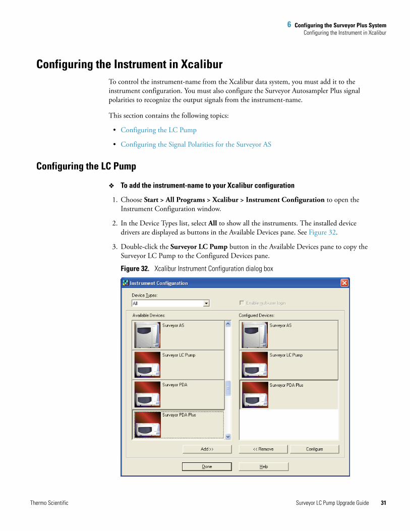
1. Choose Start > All Programs > Xcalibur > Instrument Configuration to open the Instrument Configuration window.
2. In the Device Types list, select All to show all the instruments. The installed device drivers are displayed as buttons in the Available Devices pane. See Figure 32.
3. Double-click the Surveyor LC Pump button in the Available Devices pane to copy the Surveyor LC Pump to the Configured Devices pane.
Figure 32. Xcalibur Instrument Configuration dialog box
Thermo Scientific Surveyor LC Pump Upgrade Guide 31

6 Configuring the Surveyor Plus SystemConfiguring the Instrument in Xcalibur
32
4. Double-click the Surveyor LC Pump button in the Configured Devices pane.
The Surveyor LC Pump Configuration dialog box appears. See Figure 33.
Figure 33. Surveyor LC Pump Configuration dialog box
5. In the Surveyor LC Pump Configuration dialog box, do the following:
a. In the Pressure Units list, select the units for the backpressure display.
b. In the Stack Number box, type the value for the Unit ID on the back panel of the instrument-name.
The Unit ID on the back panel of the pump consists of two rotary switches. Each switch has ten positions. The arrow on the left switch points to the “tens” digit of the Unit ID. The arrow on the right switch points to the “ones” digit of the Unit ID.
6. Click OK to close the Surveyor LC Pump dialog box.
7. Leave the Instrument Configuration view open. Go to the next procedure.
Configuring the Signal Polarities for the Surveyor AS
During an injection sequence, the instrument-name issues a pump ready signal and an injection hold release signal to the autosampler.
After you submit a run, the Surveyor AS waits for a pump ready signal from the LC pump. The instrument-name issues this signal after its pressure transducer monitors a stable backpressure. When the autosampler receives this signal, it begins an injection sequence.
After the autosampler begins the injection sequence, it waits for an injection hold release signal from the pump. The instrument-name issues this release signal when its piston cam returns to the start position. When the autosampler receives the injection hold release signal, it switches the injection valve to the inject position, allowing the mobile phase stream to sweep the contents of the sample loop onto the LC column.
For the instrument-name, select the Pump ready active high check box and the Injection hold release active high check box. See Figure 34. If you do not select these two check boxes, the autosampler does not recognize the input signals from the instrument-name and does not begin an injection sequence.
Surveyor LC Pump Upgrade Guide Thermo Scientific

6 Configuring the Surveyor Plus SystemConfiguring the Instrument in Xcalibur
To check the input signal polarities for the Surveyor Autosampler Plus
1. From the Windows XP taskbar, choose Start > All Programs > Xcalibur > Instrument Configuration to open the Instrument Configuration window if it is not already open.
2. Double-click the Surveyor Autosampler button in the Configured Devices pane to open the Surveyor Autosampler Configuration dialog box.
3. Click the Signal polarity tab to open the Signal polarity page. See Figure 34.
4. Make sure that the Pump ready active high and the Injection hold release active high check boxes are selected.
5. Click OK to close the Surveyor Autosampler Configuration dialog box.
6. Click Done to close the Instrument Configuration view.
Figure 34. Configuring the input signal polarities for the Surveyor Autosampler
Thermo Scientific Surveyor LC Pump Upgrade Guide 33


I
Index
Aautosampler
configuring the signal polarities in ChromQuest 30configuring the signal polarity settings in Xcalibur 33
Bback panel connections for firmware downloads 9backpressure 29baud rate 10bin files 14
Ccables
connected to the Interconnect PCB 4LED, connecting 5LED, detaching (figure) 3LED, disconnecting 3serial communication 8
Caution about interrupting the firmware download process 17
Change Directory dialog box 12chassis, removing screws 4ChromQuest
CD-ROM 9configuring instruments 27configuring the signal polarities for the autosampler 30location of firmware files 15monitoring the system backpressure 29opening 26upgrade utilities 15
Comm LED, flashing amber 9communication firmware files 14communication settings 10configuration in Xcalibur, pump 31
Ddrainage cone, removing 3
EEthernet cables (figure) 9
FFirmware
cable connections for a firmware download 16file types 14files for the pump ethernet converter board 18upgrading with Surveyor Upgrade Utility 14
IInstrument Configuration dialog box (figure) 27interconnect PCB (figure) 5internal components of pump (figure) 4
Jjumper used for shorting pins 9 and 15 on the back panel of the pump (figure) 8
Kkit contents 1
Llabels 23LED cable, detaching 3LPump Control Firmware folder contents 10
MMain Menu window in ChromQuest, accessing 26minicombicon connector 8
Pparts list for the Surveyor LC Pump Upgrade kit 1Port setting 10pressure units 29
Thermo Scientific Surveyor LC Pump Upgrade Guide 35

36
Index: R
pressure, monitoring in ChromQuest 29pump, configuring in Xcalibur 31
Rretention time reproducibility ixretry count 10
Sscrews
securing chassis to pump housing (figure) 4securing the interconnect PCB 5
Signal label, placement 23software CD-ROMs, part numbers 1Stack ID 29status of LEDs
after the pump is turned on for normal operation 19during a firmware download 9
Surveyor dialog box (figure) 28Surveyor Firmware folder, location for Xcalibur 15Surveyor Firmware Upgrade Utility (figure) 17Surveyor LC Pump Configuration dialog box (figure) 29
TTime out setting 10
UUnit ID
set to 00 (figure) 8set to 01 (figure) 19
units, configuring the pressure display in ChromQuest 29Upgrade label, placement 23
XXcalibur
configuring the pump 31configuring the signal polarities for the autosampler 33location of firmware folder 15
Surveyor LC Pump Upgrade Guide Thermo Scientific