Embed Size (px)
Citation preview
- 1 -
Survey on Unicast Routing in Mobile Ad Hoc Networks
Avinash Kashyap, Hitendra Nishar, Parag Agarwal
Computer Science Department, University of Texas at Dallas, TX 75083
E-mail: {avinsah,hnishar,pxa016500}@utdallas.edu
November 12, 2001
Abstract
Mobile Ad hoc Network (MANET) is a multihop wireless network of mobile nodes without any fixed infrastructure. In the absence of dedicated routers, every node contributes towards the configuration and maintenance of the routing framework. Routing protocols need to consider inter-related factors like node mobility, bandwidth scarcity and energy constraints. This survey paper attempts to outline various unicast routing techniques for mobile ad hoc networks. It briefly describes a comparative analysis with respect to routing methodology and performance.
1. Introduction Traditional telephone networks and cellular wireless networks are based on fixed and wired backbone infrastructure. In traditional telephone network, nodes have zero mobility whereas in cellular networks, the mobile nodes are constantly communicating with base stations, which form the wired backbone with mobile switching center. Sometimes it becomes really necessary for the mobile nodes to communicate with each other without any fixed infrastructure. Such situation can easily occur in battlefield, emergency search and rescue operation where providing fixed infrastructure would not be possible or would be very costly. Virtual classrooms or communication setup in exhibition, conference or meetings might be some other possible scenarios. Also in future �wearable� computing might be a potential application. The demand for such infrastructure-less mobile computing has given rise to a different type of wireless network known as mobile ad hoc network or MANET. Actually this concept of on-the-fly ad hoc network of mobile nodes dates back to DARPA packet radio network days of early 70's and 80's. Although it was known as Mobile mesh networking and Mobile Multi hop Wireless Networking in those days. The mobile nodes in MANET form on-the-fly communication backbone, which changes dynamically and arbitrarily over a period of time. Also such a network may operate in isolation or in conjunction with a fixed network. Routes between nodes in such network may consist of one or more hops. Thus each node should either itself act as router or should depend on some other node for routing. In general a typical mobile ad hoc network would have following characteristics [5]: -
• Dynamic topologies: The nodes inside the network move around randomly and have no restriction on their distance from other nodes. As a result of this random movement, the whole topology is changing in an unpredictable manner, which gives rise to both directional as well as unidirectional links between the nodes.
• Bandwidth constraints: In wireless mode of communication, the available bandwidth is lesser in comparison with wired mode of communication. On top of that interference, noise leads to signal
- 2 -
fading and thus degrades the throughput. As a result of this, congestion becomes a bottleneck in bandwidth utilization.
• Energy constraints: Most of the nodes in an ad hoc network operate on batteries that might deplete as a result of the extra work that they need to do in order to survive in the network.
• Limited Physical security: The ad hoc network is a distributed system and all the security threats relevant to such a system are pretty much present such as spoofing, masquerading, denial of service attacks, eavesdropping and data integrity.
• Self-operated: Each node should be capable enough of discovering its neighboring nodes and help in forming the communication backbone. Also it should take active participation in packet routing and/or forwarding.
The abovementioned characteristics make it absolutely necessary to develop new routing protocol for ad hoc environment. Some of the desirable properties of such a routing protocol would be [5][17]: -
• Distributed operation: Centralized approach will not give us a feasible solution since ad hoc network is fundamentally a distributed system. Moreover a central system is a single point of failure.
• Fast adaptability to link changes: The network topology keeps on changing randomly, which demands for the protocol to adapt to these changes in order to avoid miss-routing of packets.
• Stable route selection: In order to minimize the above problem, the routing algorithm can choose routes, which have high probability to remain stable for longer periods of time.
• Localized reaction to topological changes: Some drastic changes in far of part of the network should have no or minimum impact in local vicinity as far as routing decisions are concerned.
• Loop avoidance: Protocol should be able to detect loops in path or should be able to avoid it altogether in order to make routing efficient and robust.
• Unidirectional Link support: The presence of a unidirectional link in a mobile ad hoc network has a higher probability than that in a wired network. In some cases where two unidirectional links in opposite direction form the only means of communication between two ad hoc zones, the unidirectional link support would prevent unnecessary network partitioning.
• Multiple route Information: In order to increase the probability of data delivery, if possible a node should keep track of multiple routes to the destination.
• Security: The protocol should be robust enough to survive under security attacks like spoofing, masquerading, replay attack and denial of service attack.
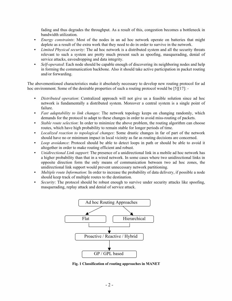
Fig. 1 Classification of routing approaches in MANET
Flat Hierarchical
Proactive / Reactive / Hybrid
GP / GPL based
Ad hoc Routing Approaches
- 3 -
Possible classifications of design choices for routing protocols in MANET would be [17]: - • Flat versus hierarchical (cluster- based) approach. • Proactive (or table driven) versus reactive (or on-demand) versus hybrid approach. • Global Position (GP) versus Global Position-Less (GPL) based protocol.
In Flat routing approach every node is equally responsible for forming and maintaining the routing information. The hierarchical approach logically restructures the network into clusters with clusterheads forming the virtual backbone for routing. Thus the number of nodes participating in the formation and maintenance of routes is less as compared to that of flat routing approach. Proactive routing approach attempts to maintain consistent routing information to all the nodes in the network at all times. This can be achieved by exchanging routing information among nodes periodically. Reactive routing approach is event driven, in which routing information is exchanged between nodes in case of topology change or route discovery. Hybrid approach seeks to combine best features of both the above approaches. Global Positioning based protocol relies on Global Positioning System (GPS) to obtain geographical location of destination node in order to optimize the route discovery. This paper proceeds with describing various existing routing protocols under flat and hierarchical approaches. Then it discusses the issues related to unidirectional wireless links for flat routing approach. In the next section it outlines the performance comparison of some of the well-known flat routing protocols. It ends up with future challenges for routing in MANET. 2. Flat Routing Approach 2.1 Proactive Routing Protocols Proactive protocols require each node to maintain one or more tables to store routing information, and they respond to changes in network topology by propagating updates throughout the network in order to maintain a consistent network view. The areas in which they differ are the number of necessary routing related tables and the methods by which changes in network structure are broadcast. [22] 2.1.1 Highly Dynamic Destination-Sequenced Distance-Vector Routing (DSDV) [19] This is a proactive routing protocol and is based on modified Bellman-ford algorithm. It overcomes some of the weaknesses of Bellman Ford algorithm like poor looping properties in case of broken links. Each node maintains a routing table, which lists all the available destinations; hop count and next hop for each destination. Also, each routing table entry is tagged with a sequence number, which is originated from the destination node. This sequence number is even when generated by destination node itself or odd when generated by one the neighboring node of the crashed node or broken link. Since the sequence number chosen for broken link is one more than the last valid route's sequence number it prevents the further propagation of stale route information. The exchange of routing table is both time-driven and event driven. Routing tables are either exchanged periodically, to maintain the consistency of highly dynamic nature of network, or whenever a change in topology is detected. The regular routing update is exchanged by broadcasting whereas the change in topology is propagated by multicasting. Routes with more recent sequence numbers are always preferred as the basis for making forwarding decisions, but not necessarily advertised. For the paths with the same sequence number, the one with the smallest metric (hop count in this case) is preferred for routing updates.
- 4 -
The route update at a node is triggered in response to every incoming routing update with most recent and better metric information. This leads to a lot of traffic in network. The algorithm attempts to minimize this by waiting for best route information based on weighted average of the most recent update of route for each destination. One of the drawbacks of this algorithm is that it doesn�t address the issue of abrupt jump in sequence number from an expected value. 2.1.2 Adaptive Distance Vector Routing Algorithm [4] This proactive protocol with some on-demand characteristics is based on distance vector algorithm, DSDV. But it adapts to the changing network load and node mobility by varying the size and frequency of updates dynamically. It reduces the size of update by exchanging the route updates for the active receivers i.e. the nodes that are receivers for any ongoing communication. In order to distinguish active receivers from others, every node has a special flag, receiver flag, corresponding to every entry in the routing table. To establish the connection, the sender floods the whole network with init-connection control packet. The receiver, if it is not an active receiver currently, makes network-wide broadcast of receiver-alert control packet. With this pair of broadcasts, all the nodes come to know about active receiver and the route to it. Even if some node loses these broadcasts, it will come to know about it when any of its neighbors sends the next update. Before closing the connection, the sender broadcasts network-wide an end-connection control packet. If the destination node has no other active connection, then it broadcasts network-wide non-receiver-alert control packet. On hearing these broadcasts, every node turns off the receiver flag corresponding this particular active receiver. In order to avoid reordering of messages, a sequence number is incremented and transmitted in every broadcast at the originating node. All the nodes currently engaged in forwarding data packets for active connections are called forwarding nodes. A node triggers an update under three conditions - i) if it has some buffered data packets due to lack of routes, ii) if one or more of its neighbors make a request for fresh routes, iii) if a forwarding node wants to advertise any fresh valid/invalid routes to the destination. The updates can be partial or full. Every node maintains a trigger meter, which has four possible values TRGMETER_FULL, TRGMETER_HIGH, TRGMETER_MED, TRGMETER_LOW and trigger threshold. When trigger meter is TRGMETER_FULL, an immediate full update is scheduled. Any one of the remaining three values is dynamically assigned to trigger threshold, which is used to decide when partial update is triggered. Trigger threshold value is computed from recent history every time after a full update is made. If the number of changes (i.e. addition/deletion of nodes in immediate neighborhood) observed by a node is higher than a preset value, then it categorizes the network as HIGH_SPEED and LOW_SPEED otherwise. While sending the routing updates, every node includes expected response and Is_receiver as a part of message. Expected response value can be HIGH when there are some buffered packets waiting due to lack of route knowledge, MEDIUM for a forwarding node in HIGH_SPEED network, LOW for a forwarding node in LOW_SPEED network and ZERO otherwise. Receiver flag is copied in Is_receiver field. When a node receives partial/full update, it accumulates expected response of all the entries and calculates the trigger meter. If trigger meter is TRGMETER_FULL, than an immediate full update is scheduled else depending on the value of trigger threshold, a partial update is scheduled. It stands between proactive and reactive approaches on account of number of routing updates done periodically. But this algorithm cannot be classified as a hybrid algorithm, which uses proactive routing in certain regions of a network and reactive routing in the remaining part of the network.
- 5 -
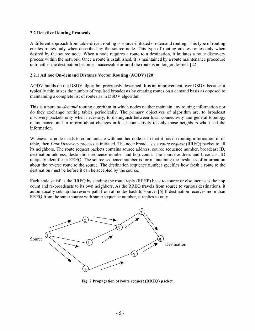
2.2 Reactive Routing Protocols A different approach from table-driven routing is source-initiated on-demand routing. This type of routing creates routes only when described by the source node. This type of routing creates routes only when desired by the source node. When a node requires a route to a destination, it initiates a route discovery process within the network. Once a route is established, it is maintained by a route maintenance procedure until either the destination becomes inaccessible or until the route is no longer desired. [22] 2.2.1 Ad hoc On-demand Distance Vector Routing (AODV) [20] AODV builds on the DSDV algorithm previously described. It is an improvement over DSDV because it typically minimizes the number of required broadcasts by creating routes on a demand basis as opposed to maintaining a complete list of routes as in DSDV algorithm. This is a pure on-demand routing algorithm in which nodes neither maintain any routing information nor do they exchange routing tables periodically. The primary objectives of algorithm are, to broadcast discovery packets only when necessary, to distinguish between local connectivity and general topology maintenance, and to inform about changes in local connectivity to only those neighbors who need the information. Whenever a node needs to communicate with another node such that it has no routing information in its table, then Path Discovery process is initiated. The node broadcasts a route request (RREQ) packet to all its neighbors. The route request packets contains source address, source sequence number, broadcast ID, destination address, destination sequence number and hop count. The source address and broadcast ID uniquely identifies a RREQ. The source sequence number is for maintaining the freshness of information about the reverse route to the source. The destination sequence number specifies how fresh a route to the destination must be before it can be accepted by the source. Each node satisfies the RREQ by sending the route reply (RREP) back to source or else increases the hop count and re-broadcasts to its own neighbors. As the RREQ travels from source to various destinations, it automatically sets up the reverse path from all nodes back to source. [6] If destination receives more than RREQ from the same source with same sequence number, it replies to only 1,3 Source Destination
Fig. 2 Propagation of route request (RREQ) packet.
1
2
3
4
5
6
7
8
- 6 -
Source Destination
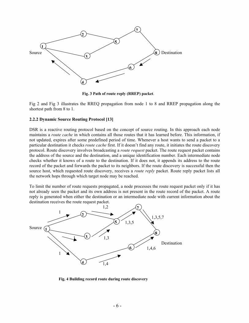
Fig. 3 Path of route reply (RREP) packet.
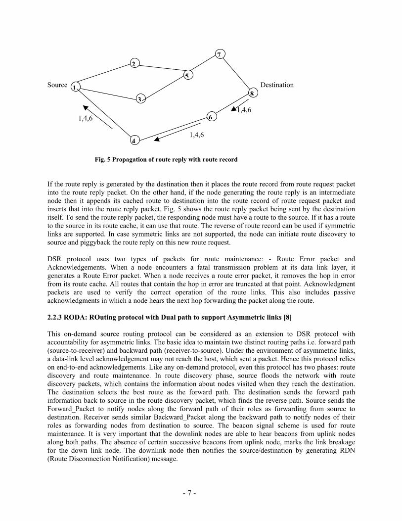
Fig 2 and Fig 3 illustrates the RREQ propagation from node 1 to 8 and RREP propagation along the shortest path from 8 to 1. 2.2.2 Dynamic Source Routing Protocol [13] DSR is a reactive routing protocol based on the concept of source routing. In this approach each node maintains a route cache in which contains all those routes that it has learned before. This information, if not updated, expires after some predefined period of time. Whenever a host wants to send a packet to a particular destination it checks route cache first. If it doesn�t find any route, it initiates the route discovery protocol. Route discovery involves broadcasting a route request packet. The route request packet contains the address of the source and the destination, and a unique identification number. Each intermediate node checks whether it knows of a route to the destination. If it does not, it appends its address to the route record of the packet and forwards the packet to its neighbors. If the route discovery is successful then the source host, which requested route discovery, receives a route reply packet. Route reply packet lists all the network hops through which target node may be reached. To limit the number of route requests propagated, a node processes the route request packet only if it has not already seen the packet and its own address is not present in the route record of the packet. A route reply is generated when either the destination or an intermediate node with current information about the destination receives the route request packet. 1,2 1 1,3,5,7 1,3,5 Source 1 1,3 Destination 1,4,6 1 1,4
Fig. 4 Building record route during route discovery
1
3
4
6
8
72
5
1
2
3
4
5
6
7
8
- 7 -
Source Destination 1,4,6 1,4,6 1,4,6
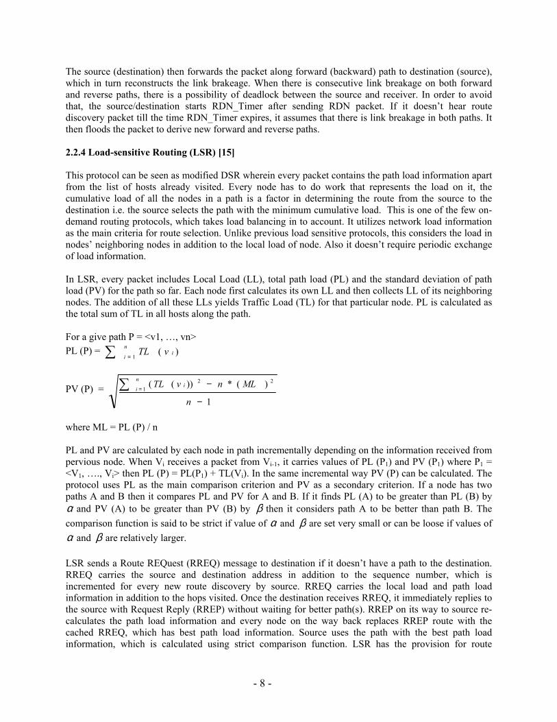
Fig. 5 Propagation of route reply with route record If the route reply is generated by the destination then it places the route record from route request packet into the route reply packet. On the other hand, if the node generating the route reply is an intermediate node then it appends its cached route to destination into the route record of route request packet and inserts that into the route reply packet. Fig. 5 shows the route reply packet being sent by the destination itself. To send the route reply packet, the responding node must have a route to the source. If it has a route to the source in its route cache, it can use that route. The reverse of route record can be used if symmetric links are supported. In case symmetric links are not supported, the node can initiate route discovery to source and piggyback the route reply on this new route request. DSR protocol uses two types of packets for route maintenance: - Route Error packet and Acknowledgements. When a node encounters a fatal transmission problem at its data link layer, it generates a Route Error packet. When a node receives a route error packet, it removes the hop in error from its route cache. All routes that contain the hop in error are truncated at that point. Acknowledgment packets are used to verify the correct operation of the route links. This also includes passive acknowledgments in which a node hears the next hop forwarding the packet along the route. 2.2.3 RODA: ROuting protocol with Dual path to support Asymmetric links [8] This on-demand source routing protocol can be considered as an extension to DSR protocol with accountability for asymmetric links. The basic idea to maintain two distinct routing paths i.e. forward path (source-to-receiver) and backward path (receiver-to-source). Under the environment of asymmetric links, a data-link level acknowledgement may not reach the host, which sent a packet. Hence this protocol relies on end-to-end acknowledgements. Like any on-demand protocol, even this protocol has two phases: route discovery and route maintenance. In route discovery phase, source floods the network with route discovery packets, which contains the information about nodes visited when they reach the destination. The destination selects the best route as the forward path. The destination sends the forward path information back to source in the route discovery packet, which finds the reverse path. Source sends the Forward_Packet to notify nodes along the forward path of their roles as forwarding from source to destination. Receiver sends similar Backward_Packet along the backward path to notify nodes of their roles as forwarding nodes from destination to source. The beacon signal scheme is used for route maintenance. It is very important that the downlink nodes are able to hear beacons from uplink nodes along both paths. The absence of certain successive beacons from uplink node, marks the link breakage for the down link node. The downlink node then notifies the source/destination by generating RDN (Route Disconnection Notification) message.
7
1
2
3
5
8
6
4
- 8 -
The source (destination) then forwards the packet along forward (backward) path to destination (source), which in turn reconstructs the link brakeage. When there is consecutive link breakage on both forward and reverse paths, there is a possibility of deadlock between the source and receiver. In order to avoid that, the source/destination starts RDN_Timer after sending RDN packet. If it doesn�t hear route discovery packet till the time RDN_Timer expires, it assumes that there is link breakage in both paths. It then floods the packet to derive new forward and reverse paths. 2.2.4 Load-sensitive Routing (LSR) [15] This protocol can be seen as modified DSR wherein every packet contains the path load information apart from the list of hosts already visited. Every node has to do work that represents the load on it, the cumulative load of all the nodes in a path is a factor in determining the route from the source to the destination i.e. the source selects the path with the minimum cumulative load. This is one of the few on-demand routing protocols, which takes load balancing in to account. It utilizes network load information as the main criteria for route selection. Unlike previous load sensitive protocols, this considers the load in nodes� neighboring nodes in addition to the local load of node. Also it doesn�t require periodic exchange of load information. In LSR, every packet includes Local Load (LL), total path load (PL) and the standard deviation of path load (PV) for the path so far. Each node first calculates its own LL and then collects LL of its neighboring nodes. The addition of all these LLs yields Traffic Load (TL) for that particular node. PL is calculated as the total sum of TL in all hosts along the path. For a give path P = <v1, �, vn> PL (P) = ∑ =
n
iivTL
1)(
PV (P) = 1
)(*))((1
22
−
−∑ =
n
MLnvTLn
ii
where ML = PL (P) / n PL and PV are calculated by each node in path incrementally depending on the information received from pervious node. When Vi receives a packet from Vi-1, it carries values of PL (P1) and PV (P1) where P1 = <V1, �., Vi> then PL (P) = PL(P1) + TL(Vi). In the same incremental way PV (P) can be calculated. The protocol uses PL as the main comparison criterion and PV as a secondary criterion. If a node has two paths A and B then it compares PL and PV for A and B. If it finds PL (A) to be greater than PL (B) by α and PV (A) to be greater than PV (B) by β then it considers path A to be better than path B. The comparison function is said to be strict if value of α and β are set very small or can be loose if values of α and β are relatively larger. LSR sends a Route REQuest (RREQ) message to destination if it doesn�t have a path to the destination. RREQ carries the source and destination address in addition to the sequence number, which is incremented for every new route discovery by source. RREQ carries the local load and path load information in addition to the hops visited. Once the destination receives RREQ, it immediately replies to the source with Request Reply (RREP) without waiting for better path(s). RREP on its way to source re-calculates the path load information and every node on the way back replaces RREP route with the cached RREQ, which has best path load information. Source uses the path with the best path load information, which is calculated using strict comparison function. LSR has the provision for route
- 9 -
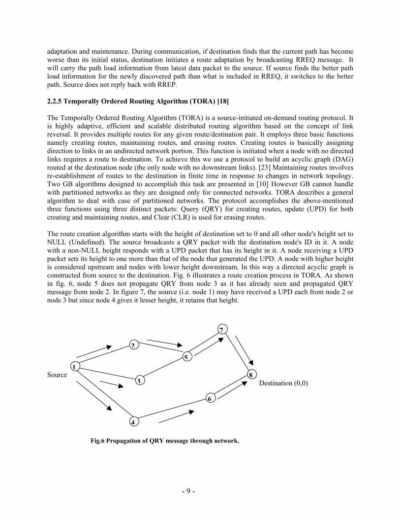
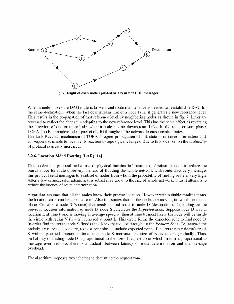
adaptation and maintenance. During communication, if destination finds that the current path has become worse than its initial status, destination initiates a route adaptation by broadcasting RREQ message. It will carry the path load information from latest data packet to the source. If source finds the better path load information for the newly discovered path than what is included in RREQ, it switches to the better path. Source does not reply back with RREP. 2.2.5 Temporally Ordered Routing Algorithm (TORA) [18] The Temporally Ordered Routing Algorithm (TORA) is a source-initiated on-demand routing protocol. It is highly adaptive, efficient and scalable distributed routing algorithm based on the concept of link reversal. It provides multiple routes for any given route/destination pair. It employs three basic functions namely creating routes, maintaining routes, and erasing routes. Creating routes is basically assigning direction to links in an undirected network portion. This function is initiated when a node with no directed links requires a route to destination. To achieve this we use a protocol to build an acyclic graph (DAG) routed at the destination node (the only node with no downstream links). [23] Maintaining routes involves re-establishment of routes to the destination in finite time in response to changes in network topology. Two GB algorithms designed to accomplish this task are presented in [10] However GB cannot handle with partitioned networks as they are designed only for connected networks. TORA describes a general algorithm to deal with case of partitioned networks. The protocol accomplishes the above-mentioned three functions using three distinct packets: Query (QRY) for creating routes, update (UPD) for both creating and maintaining routes, and Clear (CLR) is used for erasing routes. The route creation algorithm starts with the height of destination set to 0 and all other node's height set to NULL (Undefined). The source broadcasts a QRY packet with the destination node's ID in it. A node with a non-NULL height responds with a UPD packet that has its height in it. A node receiving a UPD packet sets its height to one more than that of the node that generated the UPD. A node with higher height is considered upstream and nodes with lower height downstream. In this way a directed acyclic graph is constructed from source to the destination. Fig. 6 illustrates a route creation process in TORA. As shown in fig. 6, node 5 does not propagate QRY from node 3 as it has already seen and propagated QRY message from node 2. In figure 7, the source (i.e. node 1) may have received a UPD each from node 2 or node 3 but since node 4 gives it lesser height, it retains that height. 1,3 Source Destination (0,0)
Fig.6 Propagation of QRY message through network.
1
2
3
4
5
6
8
7
- 10 -
Source Destination
Fig. 7 Height of each node updated as a result of UDP messages. When a node moves the DAG route is broken, and route maintenance is needed to reestablish a DAG for the same destination. When the last downstream link of a node fails, it generates a new reference level. This results in the propagation of that reference level by neighboring nodes as shown in fig. 7. Links are reversed to reflect the change in adapting to the new reference level. This has the same effect as reversing the direction of one or more links when a node has no downstream links. In the route erasure phase, TORA floods a broadcast clear packet (CLR) throughout the network to erase invalid routes. The Link Reversal mechanism of TORA foregoes propagation of link-state or distance information and, consequently, is able to localize its reaction to topological changes. Due to this localization the scalability of protocol is greatly increased. 2.2.6. Location Aided Routing (LAR) [14] This on-demand protocol makes use of physical location information of destination node to reduce the search space for route discovery. Instead of flooding the whole network with route discovery message, this protocol send messages to a subset of nodes from whom the probability of finding route is very high. After a few unsuccessful attempts, this subset may grow to the size of whole network. Thus it attempts to reduce the latency of route determination. Algorithm assumes that all the nodes know their precise location. However with suitable modifications, the location error can be taken care of. Also it assumes that all the nodes are moving in two-dimensional plane. Consider a node S (source) that needs to find route to node D (destination). Depending on the previous location information of node D, node S calculates the Expected zone. Suppose node D was at location L at time t1 and is moving at average speed V, then at time t2, most likely the node will be inside the circle with radius V (t2 � t1), centered at point L. This circle forms the expected zone to find node D. In order find the route, node S floods the discovery request throughout the Request Zone. To increase the probability of route discovery, request zone should include expected zone. If the route reply doesn�t reach S within specified amount of time, then node S increases the size of request zone gradually. Thus, probability of finding node D is proportional to the size of request zone, which in turn is proportional to message overhead. So, there is a tradeoff between latency of route determination and the message overhead. The algorithm proposes two schemes to determine the request zone.
7
1
2
3
4
5
8
6
- 11 -
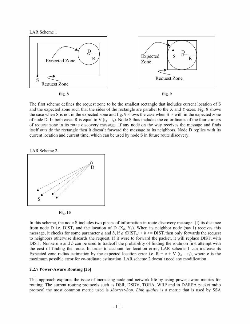
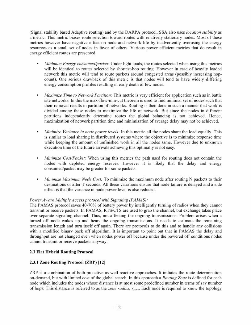
LAR Scheme 1 Fig. 8 Fig. 9 The first scheme defines the request zone to be the smallest rectangle that includes current location of S and the expected zone such that the sides of the rectangle are parallel to the X and Y-axes. Fig. 8 shows the case when S is not in the expected zone and fig. 9 shows the case when S is with in the expected zone of node D. In both cases R is equal to V (t2 � t1). Node S thus includes the co-ordinates of the four corners of request zone in its route discovery message. If any node on the way receives the message and finds itself outside the rectangle then it doesn�t forward the message to its neighbors. Node D replies with its current location and current time, which can be used by node S in future route discovery. LAR Scheme 2 Fig. 10 In this scheme, the node S includes two pieces of information in route discovery message. (I) its distance from node D i.e. DISTs and the location of D (Xd, Yd). When its neighbor node (say I) receives this message, it checks for some parameter a and b, if a (DISTs) + b >= DISTi then only forwards the request to neighbors otherwise discards the request. If it were to forward the packet, it will replace DISTs with DISTi. Nonzero a and b can be used to tradeoff the probability of finding the route on first attempt with the cost of finding the route. In order to account for location error, LAR scheme 1 can increase its Expected zone radius estimation by the expected location error i.e. R = e + V (t2 � t1), where e is the maximum possible error for co-ordinate estimation. LAR scheme 2 doesn�t need any modification. 2.2.7 Power-Aware Routing [25] This approach explores the issue of increasing node and network life by using power aware metrics for routing. The current routing protocols such as DSR, DSDV, TORA, WRP and in DARPA packet radio protocol the most common metric used is shortest-hop. Link quality is a metric that is used by SSA
S
RExpected Zone
Request Zone
D
S
D
RD
S Expected
Zone
Request Zone
- 12 -
(Signal stability based Adaptive routing) and by the DARPA protocol. SSA also uses location stability as a metric. This metric biases route selection toward routes with relatively stationary nodes. Most of these metrics however have negative effect on node and network life by inadvertently overusing the energy resources as a small set of nodes in favor of others. Various power efficient metrics that do result in energy efficient routes are presented.
• Minimum Energy consumed/packet: Under light loads, the routes selected when using this metrics will be identical to routes selected by shortest-hop routing. However in case of heavily loaded network this metric will tend to route packets around congested areas (possibly increasing hop-count). One serious drawback of this metric is that nodes will tend to have widely differing energy consumption profiles resulting in early death of few nodes.
• Maximize Time to Network Partition: This metric is very efficient for application such as in battle
site networks. In this the max-flow-min-cut theorem is used to find minimal set of nodes such that their removal results in partition of networks. Routing is then done in such a manner that work is divided among these nodes to maximize the life of network. But since the nodes in different partitions independently determine routes the global balancing is not achieved. Hence, maximization of network partition time and minimization of average delay may not be achieved.
• Minimize Variance in node power levels: In this metric all the nodes share the load equally. This
is similar to load sharing in distributed systems where the objective is to minimize response time while keeping the amount of unfinished work in all the nodes same. However due to unknown execution time of the future arrivals achieving this optimally is not easy.
• Minimize Cost/Packet: When using this metrics the path used for routing does not contain the
nodes with depleted energy reserves. However it is likely that the delay and energy consumed/packet may be greater for some packets.
• Minimize Maximum Node Cost: To minimize the maximum node after routing N packets to their
destinations or after T seconds. All these variations ensure that node failure is delayed and a side effect is that the variance in node power level is also reduced.
Power Aware Multiple Access protocol with Signaling (PAMAS): The PAMAS protocol saves 40-70% of battery power by intelligently turning of radios when they cannot transmit or receive packets. In PAMAS, RTS/CTS are used to grab the channel, but exchange takes place over separate signaling channel. Thus, not affecting the ongoing transmissions. Problem arises when a turned off node wakes up and hears the ongoing transmissions. It needs to estimate the remaining transmission length and turn itself off again. There are protocols to do this and to handle any collisions with a modified binary back off algorithm. It is important to point out that in PAMAS the delay and throughput are not changed even when nodes power off because under the powered off conditions nodes cannot transmit or receive packets anyway. 2.3 Flat Hybrid Routing Protocol 2.3.1 Zone Routing Protocol (ZRP) [12] ZRP is a combination of both proactive as well reactive approaches. It initiates the route determination on-demand, but with limited cost of the global search. In this approach a Routing Zone is defined for each node which includes the nodes whose distance is at most some predefined number in terms of say number of hops. This distance is referred to as the zone radius, rzone. Each node is required to know the topology
- 13 -
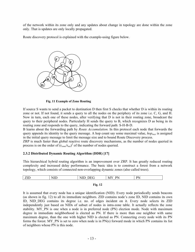
of the network within its zone only and any updates about change in topology are done within the zone only. That is updates are only locally propagated. Route discovery protocol is explained with the example-using figure below.
Fig. 11 Example of Zone Routing If source S wants to send a packet to destination D then first S checks that whether D is within its routing zone or not. If not found, it sends a query to all the nodes on the periphery of its zone i.e. C, G, and H. Now in turn, each one of these nodes, after verifying that D is not in their routing zone, broadcast the query to their peripheral nodes. Particularly H sends the query to B, which recognizes D as being in its routing zone and responds to the query, indicating the forward path: S-H-B-D. B learns about the forwarding path by Route Accumulation. In this protocol each node that forwards the query appends its identity to the query message. A hop count say some maximal value, hopmax is assigned in the initial query message to limit the message size and to bound Route Discovery process. ZRP is much faster than global reactive route discovery mechanisms, as the number of nodes queried in process is on the order of (rzone/rnet)2 of the number of nodes queried. 2.3.2 Distributed Dynamic Routing Algorithm (DDR) [17] This hierarchical hybrid routing algorithm is an improvement over ZRP. It has greatly reduced routing complexity and increased delay performance. The basic idea is to construct a forest from a network topology, which consists of connected non-overlapping dynamic zones (also called trees). ZID NID NID_DEG MY_PN PN
Fig. 12
It is assumed that every node has a unique identification (NID). Every node periodically sends beacons (as shown in fig. 12) to all its immediate neighbors. ZID contains node�s zone ID, NID contains its own ID, NID_DEG contains its degree i.e. no. of edges incident on it. Every node selects its ZID independently just based on NIDs of subset of nodes in intra-zone table. It actually reflects the zone stability. MY_PN is one when a node is in preferred node (PN) election mode. Node with maximum degree in immediate neighborhood is elected as PN. If there is more than one neighbor with same maximum degree, than the one with higher NID is elected as PN. Connecting every node with its PN forms the forest. MY_PN is set to zero when node is in PN(s) forward mode in which PN contains its list of neighbors whose PN is this node.
D
G
A
E
B
FC
HS
- 14 -
NID Learned_PN
Fig. 13
In this way, every node comes to know about every other node in the same tree and the neighbor to be contacted to reach the destination. The information about the entire tree is stored in intra-zone table (as shown in fig 13). The Learned_PN contains the list of nodes reachable from the associated NID. The no. of entries in table is equal to the degree of that node.
GNID NZID Z_Stability
Fig. 14 If a node encounters beacons with different ZID from its own, it makes the entry in inter-zone table (as shown in fig. 14). These nodes are considered to be gateway nodes. GNID is the gateway�s ID, NZID is its zone ID and Z_Stability indicates its stability. So far the algorithm has talked about forming a forest with connected non-overlapping zones. The actual routing protocol description is part of future work. 2.4. Comparison of DSR and AODV [21] Both are on-demand routing protocols but DSR uses source routing whereas AODV uses table-driven framework with sequence numbers. DSR is independent of any time activities while AODV is not to certain extent. In DSR every node(s) on path from source to destination comes to know about the path to intermediate node(s) because of source routing. Also promiscuous listening adds more knowledge of routes to the node(s). Whereas AODV depends only on route discovery because of which it has access to significantly lesser amount of information than DSR. Secondly, DSR makes effective use of route caching and the destination replies to all route discovery messages because of which the source learns about multiple path(s). But there may be a possibility of route reply flood. In AODV, destination replies to only the first RREQ and ignores the rest. Thirdly, DSR doesn�t have any explicit mechanism for expiring stale route(s) in cache. Route error packets delete some stale route cache route entries. In contrast, AODV uses sequence number and periodic expiry of table entries to remove stale entries. But it comes with the challenge of finding an optimal expiry time. 2.5 Performance Comparison of DSDV, AODV, DSR, TORA [23] For simulation, the performance was measured in terms of throughput i.e. ratio of data packets delivered to destination to those generated by the CBR (Constant Bit Rate) source and average end-to-end delay of data packets. It was found that both DSR and AODV perform equally when number of sources is low. But in case of large number of sources, DSR delivers better performance under low-mobility condition and AODV under high-mobility condition. Also, in all cases DSR always has a lower routing load than AODV.
- 15 -
Parameters DSDV AODV DSR TORA Time complexity O(d) O(2d)* O(2d)* O(2d)* Communication complexity O(N) O(2N)* O(2N)* O(2N)* Multicast capability No Yes No No Multiple Route possibility No No Yes Yes Beaconing requirement Yes No No No Routes maintained in Table Table Cache Table Utilizes route cache/table expiration timers Yes Yes No No Routing metric Shortest
path Fastest and shortest path
Shortest path
Shortest path
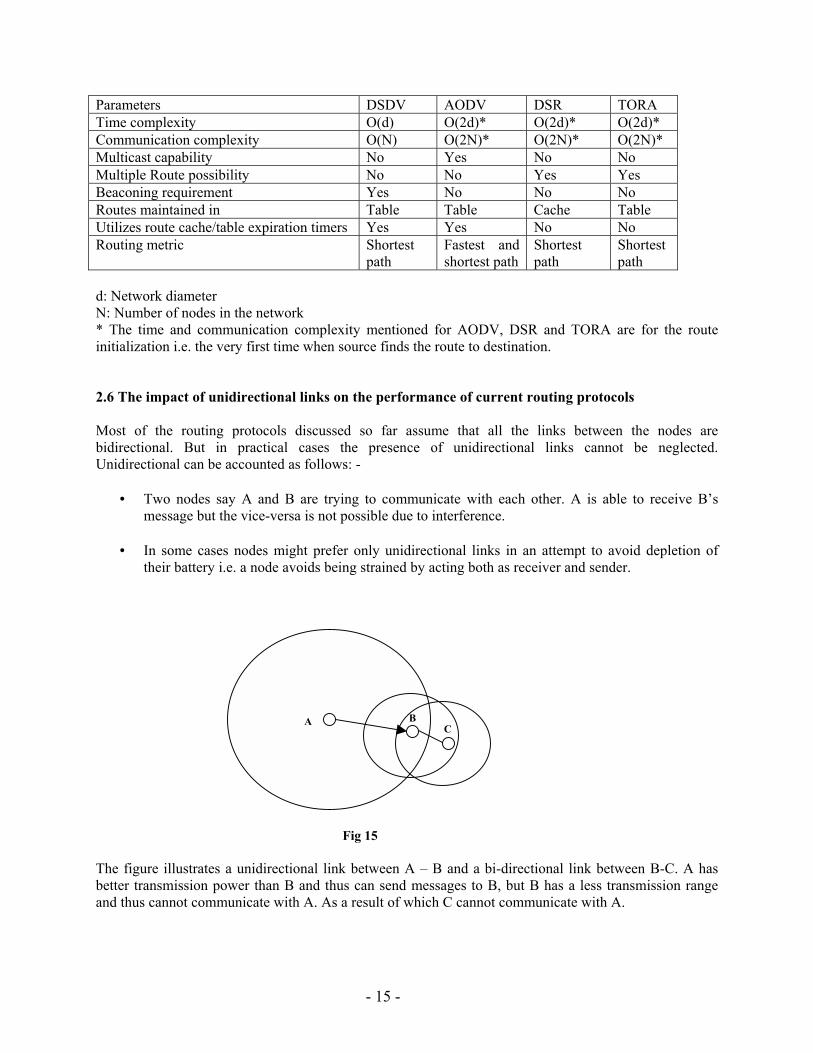
d: Network diameter N: Number of nodes in the network * The time and communication complexity mentioned for AODV, DSR and TORA are for the route initialization i.e. the very first time when source finds the route to destination. 2.6 The impact of unidirectional links on the performance of current routing protocols Most of the routing protocols discussed so far assume that all the links between the nodes are bidirectional. But in practical cases the presence of unidirectional links cannot be neglected. Unidirectional can be accounted as follows: -
• Two nodes say A and B are trying to communicate with each other. A is able to receive B�s message but the vice-versa is not possible due to interference.
• In some cases nodes might prefer only unidirectional links in an attempt to avoid depletion of
their battery i.e. a node avoids being strained by acting both as receiver and sender.
Fig 15 The figure illustrates a unidirectional link between A � B and a bi-directional link between B-C. A has better transmission power than B and thus can send messages to B, but B has a less transmission range and thus cannot communicate with A. As a result of which C cannot communicate with A.
A
C B
- 16 -
There might be cases where a link between nodes might be in a transient state from unidirectional mode to bidirectional mode. The frequency of such transitions and the time interval for a node to stay in such a state will be functions of the [22] �offered traffic, terrain, mobility pattern, and energy availability�. Unidirectional links can lead to the following problems for the existing ad hoc protocols [22]: -
• Knowledge Asymmetry: Consider a two-hop path from A to C. B is an intermediate node in such a path. B can listen to A but it should not simple assume that A is able to hear B. This is due because a unidirectional link might not be present from B to A. Information spread in one direction does not guarantee that the same information can be spread taking the same path in the opposite direction. DSDV suffers from the aforementioned drawback.
• Routing Asymmetry: This happens when deciding on the shortest paths. As already mentioned in
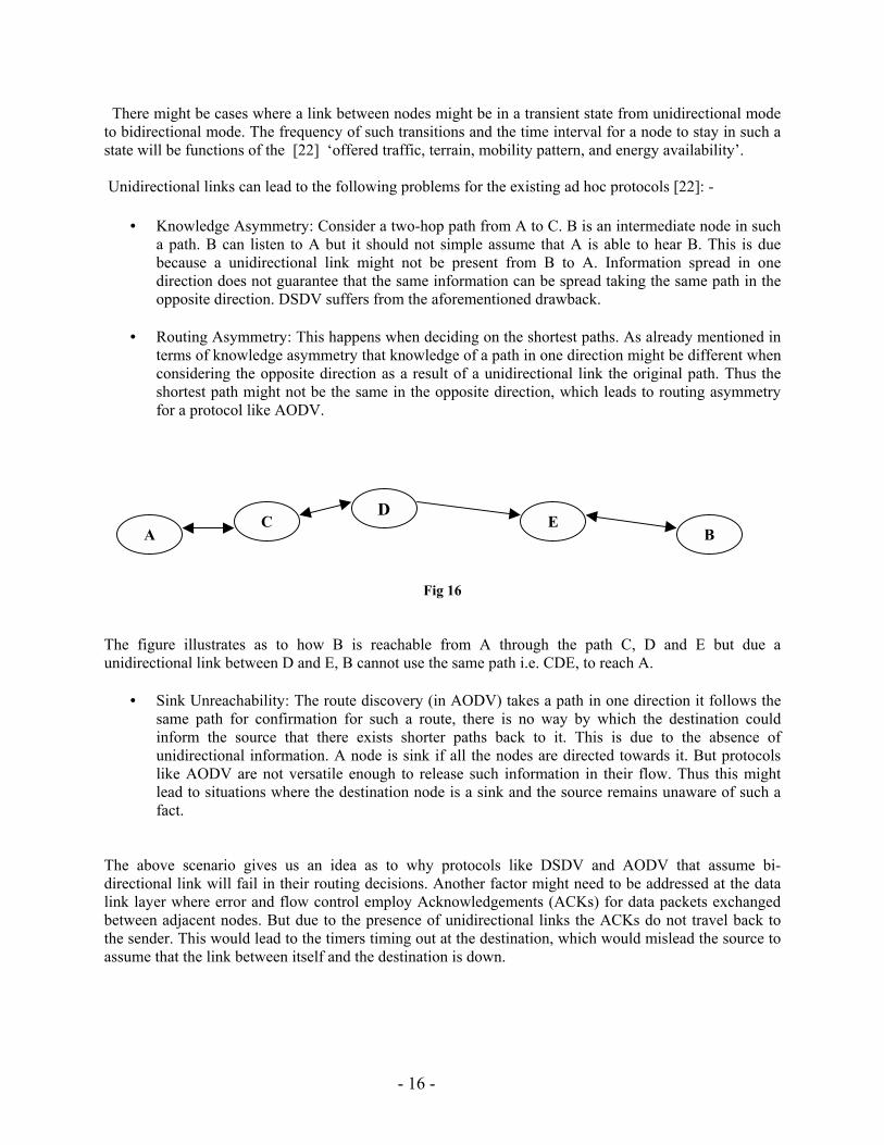
terms of knowledge asymmetry that knowledge of a path in one direction might be different when considering the opposite direction as a result of a unidirectional link the original path. Thus the shortest path might not be the same in the opposite direction, which leads to routing asymmetry for a protocol like AODV.
Fig 16 The figure illustrates as to how B is reachable from A through the path C, D and E but due a unidirectional link between D and E, B cannot use the same path i.e. CDE, to reach A.
• Sink Unreachability: The route discovery (in AODV) takes a path in one direction it follows the same path for confirmation for such a route, there is no way by which the destination could inform the source that there exists shorter paths back to it. This is due to the absence of unidirectional information. A node is sink if all the nodes are directed towards it. But protocols like AODV are not versatile enough to release such information in their flow. Thus this might lead to situations where the destination node is a sink and the source remains unaware of such a fact.
The above scenario gives us an idea as to why protocols like DSDV and AODV that assume bi-directional link will fail in their routing decisions. Another factor might need to be addressed at the data link layer where error and flow control employ Acknowledgements (ACKs) for data packets exchanged between adjacent nodes. But due to the presence of unidirectional links the ACKs do not travel back to the sender. This would lead to the timers timing out at the destination, which would mislead the source to assume that the link between itself and the destination is down.
A C
DE
B
- 17 -
In order to tackle the aforementioned problem the following methods have been proposed: - • Routing protocol with Dual path to support Asymmetric links (RODA): (Refer Section 2.2.3) this
protocol is an improvement of the DSR. • Routing with Unidirectional links [22]: This proposes a strategy that is a modification of the existing
AODV and DSDV protocols. It uses the concept of propagating information in terms of combinations of both unidirectional and bi-directional links. Thus as a result of which each node comes to know about the reachability towards other nodes and avoids problems like knowledge asymmetry, routing asymmetry and sink unreachability. But this protocol has a storage overhead of O (n2) (where n is the number of nodes) that needs to be overcome.
• [16] works with the existing routing protocols. The basic idea behind this protocol is to hide the
presence of unidirectional links by tunneling the routing information and certain ACKs. This helps in solving the problem of the data link layer where the ACKs get lost as result of the presence of unidirectional links. This protocol first finds out the unidirectional links between nodes and then uses this information to tunnel routing information as well as ACKs between data link layers between nodes. Thus this provides a transparency for Link layer ACKs and the network layer routing information exchange between neighbors.
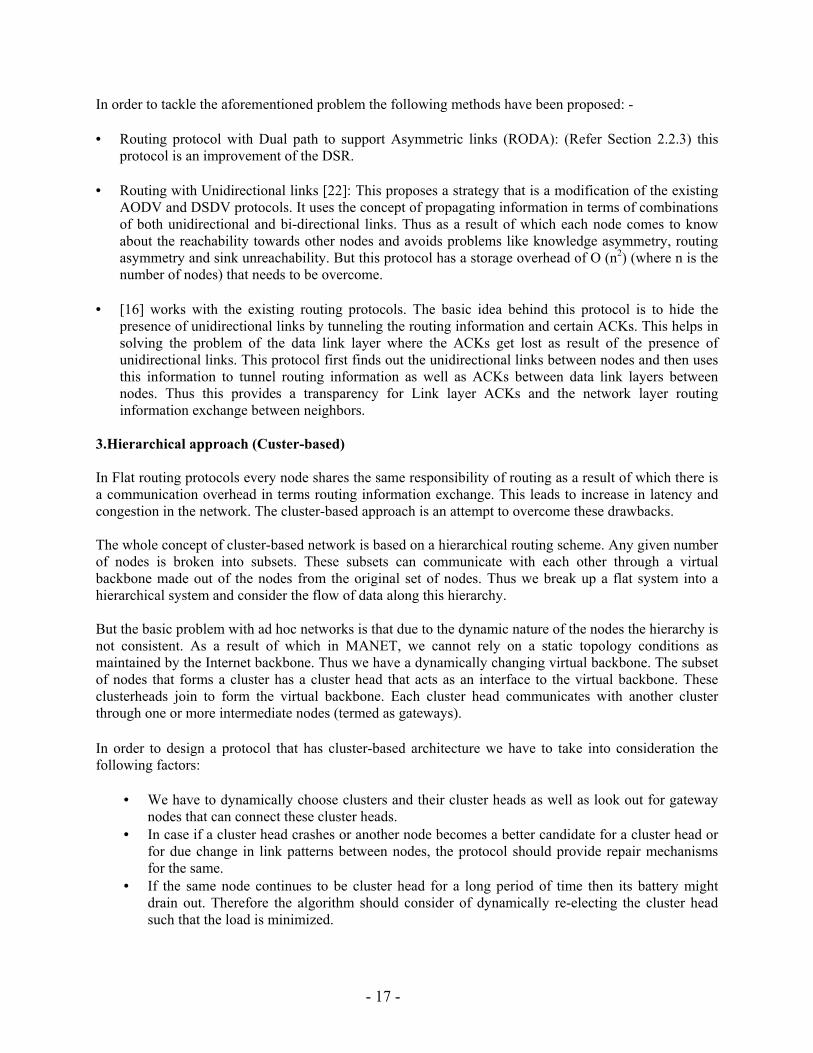
3.Hierarchical approach (Custer-based) In Flat routing protocols every node shares the same responsibility of routing as a result of which there is a communication overhead in terms routing information exchange. This leads to increase in latency and congestion in the network. The cluster-based approach is an attempt to overcome these drawbacks. The whole concept of cluster-based network is based on a hierarchical routing scheme. Any given number of nodes is broken into subsets. These subsets can communicate with each other through a virtual backbone made out of the nodes from the original set of nodes. Thus we break up a flat system into a hierarchical system and consider the flow of data along this hierarchy. But the basic problem with ad hoc networks is that due to the dynamic nature of the nodes the hierarchy is not consistent. As a result of which in MANET, we cannot rely on a static topology conditions as maintained by the Internet backbone. Thus we have a dynamically changing virtual backbone. The subset of nodes that forms a cluster has a cluster head that acts as an interface to the virtual backbone. These clusterheads join to form the virtual backbone. Each cluster head communicates with another cluster through one or more intermediate nodes (termed as gateways). In order to design a protocol that has cluster-based architecture we have to take into consideration the following factors:
• We have to dynamically choose clusters and their cluster heads as well as look out for gateway nodes that can connect these cluster heads.
• In case if a cluster head crashes or another node becomes a better candidate for a cluster head or for due change in link patterns between nodes, the protocol should provide repair mechanisms for the same.
• If the same node continues to be cluster head for a long period of time then its battery might drain out. Therefore the algorithm should consider of dynamically re-electing the cluster head such that the load is minimized.
- 18 -
• The cluster heads are prone to attacks like Denial of Service where they can be made so busy that the other nodes belonging to the cluster might become isolated from the rest of the network. This would result in a network partitioning. Moreover a node can pose as a cluster head and result in a bottleneck by not transferring data packets and even sniffing information thus compromising the data integrity. The protocol must be secure and robust enough to handle such situations.
• When deciding on virtual backbones the protocol must elect clusterheads such the throughput is maximum. The virtual backbone should consist of links that are less susceptible to asymmetry, interference and signal fading.
Figure 17 � cluster formation. The above figure gives an illustration of the virtual backbone � clusterheads, gateways and simple nodes belonging to a particular cluster. Cluster A and cluster B are connected by one gateway while Cluster B and Cluster C are connected by 2 gateways since one gateway does not cover both eh clusterheads for B and C respectively.
The basic idea of clustering dates back to the 80�s when the research started with the notion of Packet Radio Networks. This was done while taking into consideration Packet Radio Networks (PRNET), which aims at sharing a common channel efficiently among a group of moving nodes. These nodes can be considered as a fleet of battleships. In the older days the following approach was taken in order to maintain radio packet networks.
• The system were centralized where all the data to be transmitted to a group of mobile nodes were
routed through a centralized entity, thus making this entity a hot spot in the network and a central point of failure for the network.
• In order to overcome the aforementioned centralized approach, a hierarchical centralized
architecture was introduced that consisted of multiple centralized entities arranged in a hierarchy. But since this also was prone to failure of centralized nodes that could break up the hierarchy and thus would bring the system down.
• To override the aforementioned drawbacks a fully distributed system approach was used. But this
too suffered from heavy communication load between the talking entities.
- 19 -
Thus there was a need for a system that could possibly reduce the communication overhead as well as maintain a topology that remains stable over a period of time. This led to the basic idea of clustering. There has been considerable research in finding out heuristic to elect cluster heads and maintain the dynamic changing virtual backbone. We have two types of heuristics � node Id based and node connectivity based that is, a node�s links with its neighboring nodes. 3.1 Node ID based Heuristic The following methods use the node id based heuristic to elect clusterheads such that each node is either a clusterhead or almost 1- hop away from a clusterhead.
3.1.1 Linked state cluster architecture [3] This algorithm points out as to how fully distributed control methods can be combined with the hierarchal control to generate a network that is robust enough to withstand dynamic topological changes with respect to the nodes and their connectivity.
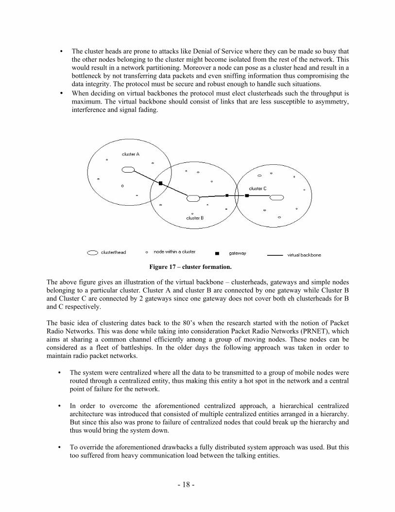
The whole concept behind the link state architecture was to reduce the communication overhead involved in fully distributed system. This uses a Link Cluster Algorithm ( LCA), which is based on synchronously timed clocks using the 2n TDMA (Time based Division Multiple Access) time slots to establish communication between n nodes. There are basically 2 frame rounds such that every node after the 2n slots ends up either becoming a clusterhead, gateway or a ordinary node, thus forming a virtual backbone by the end of the second frame. The election of a node X as a clusterhead is done using the either of the following condition being satisfied: -
Figure 18
A node X�s ID is higher then all other node Ids that are 1- hop away from it. As shown in figure 18, X has higher Id than A, B, C and D and these are 1 hop away from X.
Figure 19
- 20 -
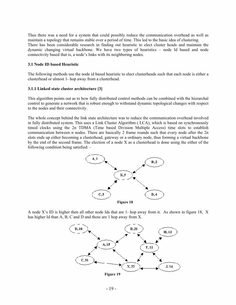
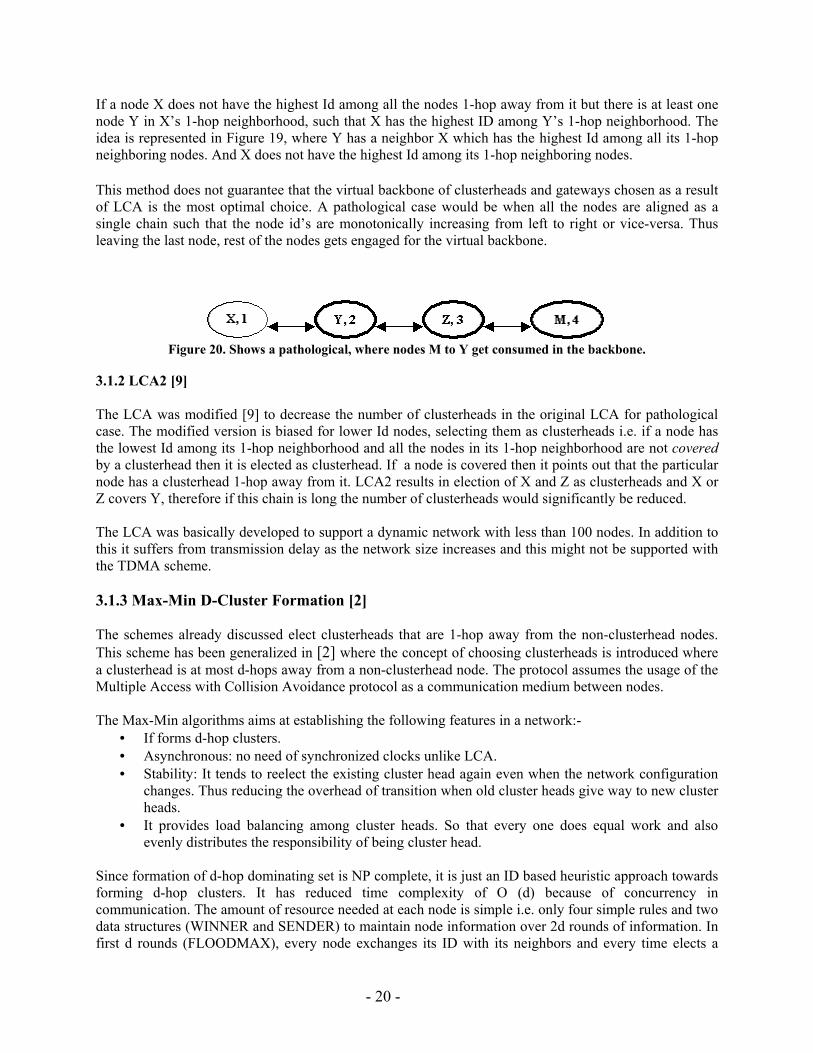
If a node X does not have the highest Id among all the nodes 1-hop away from it but there is at least one node Y in X�s 1-hop neighborhood, such that X has the highest ID among Y�s 1-hop neighborhood. The idea is represented in Figure 19, where Y has a neighbor X which has the highest Id among all its 1-hop neighboring nodes. And X does not have the highest Id among its 1-hop neighboring nodes. This method does not guarantee that the virtual backbone of clusterheads and gateways chosen as a result of LCA is the most optimal choice. A pathological case would be when all the nodes are aligned as a single chain such that the node id�s are monotonically increasing from left to right or vice-versa. Thus leaving the last node, rest of the nodes gets engaged for the virtual backbone.
Figure 20. Shows a pathological, where nodes M to Y get consumed in the backbone.
3.1.2 LCA2 [9] The LCA was modified [9] to decrease the number of clusterheads in the original LCA for pathological case. The modified version is biased for lower Id nodes, selecting them as clusterheads i.e. if a node has the lowest Id among its 1-hop neighborhood and all the nodes in its 1-hop neighborhood are not covered by a clusterhead then it is elected as clusterhead. If a node is covered then it points out that the particular node has a clusterhead 1-hop away from it. LCA2 results in election of X and Z as clusterheads and X or Z covers Y, therefore if this chain is long the number of clusterheads would significantly be reduced. The LCA was basically developed to support a dynamic network with less than 100 nodes. In addition to this it suffers from transmission delay as the network size increases and this might not be supported with the TDMA scheme. 3.1.3 Max-Min D-Cluster Formation [2] The schemes already discussed elect clusterheads that are 1-hop away from the non-clusterhead nodes. This scheme has been generalized in [2] where the concept of choosing clusterheads is introduced where a clusterhead is at most d-hops away from a non-clusterhead node. The protocol assumes the usage of the Multiple Access with Collision Avoidance protocol as a communication medium between nodes. The Max-Min algorithms aims at establishing the following features in a network:-
• If forms d-hop clusters. • Asynchronous: no need of synchronized clocks unlike LCA. • Stability: It tends to reelect the existing cluster head again even when the network configuration
changes. Thus reducing the overhead of transition when old cluster heads give way to new cluster heads.
• It provides load balancing among cluster heads. So that every one does equal work and also evenly distributes the responsibility of being cluster head.
Since formation of d-hop dominating set is NP complete, it is just an ID based heuristic approach towards forming d-hop clusters. It has reduced time complexity of O (d) because of concurrency in communication. The amount of resource needed at each node is simple i.e. only four simple rules and two data structures (WINNER and SENDER) to maintain node information over 2d rounds of information. In first d rounds (FLOODMAX), every node exchanges its ID with its neighbors and every time elects a
- 21 -
node with highest ID as the WINNER. Thus a node with highest ID in its d hops neighborhood is elected as WINNER. In next d rounds (FLOODMIN), smallest IDs rather then highest IDs are selected as WINNER. Floodmax is greedy algorithm and may result in unbalanced cluster formation. In fact, there may be situation in which the cluster head A may be separated from its cluster as a result of being overtaken by cluster head B. Floodmin actually allows nodes with smaller IDs to reclaim their territory. The node, which hears its own ID in the floodmin phase, elects itself to be clusterhead. But it has no idea of which all nodes are the members of its cluster. Thus it is every node�s responsibility to propagate membership information to its clusterhead, which is, knows as convergecast. Every node elects the node whose ID is smallest among the ones that appear at least once as WINNER in both d rounds as its cluster head. If it doesn�t have one, it elects the WINNER of round 1 as its cluster head. In some cases, the node may find some other cluster head on its way to its elected cluster head, in which case it becomes the member of the nearest cluster head. Also, after hearing from neighboring nodes about their election of cluster heads, a node will come to know if it can act as a gateway node, in which case it transmits that information to its clusterhead. This heuristics maximizes the number of gateway nodes, which helps in forming multiple paths between cluster heads. The method suffers from the drawback that every node needs to wait for its entire neighborhood to finish the current round of information exchange before proceeding to next round. [2] is comparable to the LCA [3] in terms of cluster size and cluster duration but is better in terms even distribution of clusters. It also exhibits a better level of clusterhead stability than [9]. 3.1.4 Structured Routing in Wireless Mobile Ad Hoc Networks [24] Another approach that utilizes the node Id heuristic is Structured Routing in Wireless Mobile Ad Hoc Networks [24]. This protocol emulates the traditional cellular infrastructure in wireless mobile as hoc network. It is two-step process, first to establish and maintain the infrastructure and second is to use the infrastructure to perform actual routing. The protocol used to establish the infrastructure is known as VBS (Virtual Base Station) infrastructure-creation protocol. This protocol elects a subset of nodes as VBS in distributed fashion based on some predefined criteria e.g. node with smallest ID. The rest of the nodes in the network are known as MTs (Mobile Terminal). The VBS and the nodes under its control keep on exchanging hello messages on regular basis. Thus VBS keeps track of the nodes under its control. If VBS doesn�t respond to the Hello packet for a period of time, it considered to be dead and a new VBS is elected. Every node maintains a variable called myVBS, which contains the ID of its VBS. It is set to 0 for the VBS itself. VBS maintains information about the whole network i.e. all the VBS and their corresponding node lists. The protocol to perform routing is known as VBS Routing Protocol. An MT contacts its own VBS for the delivery of the packets to the destination node. Every VBS maintains a field called BMT (Border Mobile Terminal) for every other VBS in the network. BMT contains the ID of node, which can forward the packet to the next VBS on the way to the destination. When VBS receives a packet from an MT, it looks up at the BMT entry for the VBS in charge of the destination node. VBS then forwards the packet to the node specified in BMT entry. BMT may point to destination VBS or an MT. The same procedure is performed at all the nodes on the way to destination. In this algorithm, MTs are neither responsible for establishing routes nor maintaining the existing ones. Hence, it saves the time spent on route discovery. But, it suffers from two drawbacks. First it has the overhead of electing/reelecting the VBS. Second, every VBS needs to keep track of changing topology by communicating with all other VBSs periodically.
- 22 -
3.2 Connectivity based heuristic. We need to optimize the number of cluster heads present in the backbone. The goal shifts to minimizing the cluster heads and this can be achieved by election of cluster heads based on the connection between the nodes. The Dominating Set is a popular approach used for detecting such cluster heads in a given topology. The problem is similar to the coloring graph problem where we have to color adjacent nodes of a graph using the minimum number of colors. In the dominating set scenario, the dominating set is a subset of the given number of nodes. Moreover a node in the topology is either a member of the dominating set or is one hop away from the dominating set. The basic scheme aims at minimizing the size of the dominating set to form a maximal independent set. A member of the maximal independent set can act as the cluster head and is said to dominate a given set of nodes, which are one hop away from it. A member of the dominating set can also act as a gateway. The election of these cluster heads is made on their connectivity to their neighbors. There have been different protocols proposed on the same approach. Some of them are as follows: - 3.2.1 Routing in Ad hoc networks Using Minimum Connected Dominating Sets [7] This protocol uses the concept of dominating set and as an attempt to optimize the dominating set it selects the minimum connected dominating set i.e. out of all possible connected dominating set the algorithm chooses the set with minimum number of members. The algorithm also finds out the shortest path for routing and route updates with dynamically changing topology. 3.2.2 Core-Extraction Distributed Ad hoc Routing Algorithm [26] This protocol makes its routing decision based on QoS. The virtual backbone is termed as core and is basically computed using the Minimum Dominating Set scheme. This is done by maintaining local states and executing local computations. Propagating the bandwidth information across the virtual backbone performs QoS routing. The protocol aims at informing about stable links across the core while maintains local information about the unstable links with low bandwidth. The link state information of stable high bandwidth link propagates using the slow-moving increase waves and fast-moving decrease waves. The route from the source to the destination is computed talking into account the maximum available bandwidth path with minimum number of hops (� shortest-widest path �[26]). 3.3 Hybrid of Node ID and Connectivity Based heuristic 3.3.1 Multicluster, mobile, multimedia radio network, mentions about �wireless adaptive mobile information systems� [11] The network in [11], uses a clustering algorithm, which is node id based heuristic where the selection of the clusterheads is made primarily on the basis of lowest id cluster algorithm or the highest connectivity cluster algorithm. Both the schemes result in cluster based network where neither of the cluster heads are directly linked and in a cluster any two given nodes are two hop away from each other, as they might be directly linked or through the clusterhead. The clusterheads coordinates the following issues pertaining to the cluster: - • resolving channel scheduling • perform power measurement / control. • Time division synchronization • Enhancement of spatial reuse of time slots and codes
- 23 -
The algorithm used here guarantees bandwidth support for real time traffic and allocation of bandwidth to virtual circuits at call setup time. The algorithm is scalable to a large number of nodes as well can handle dynamic changing topology where in nodes leave and join different clusters. 3.4 Load Balancing among cluster heads. As we have seen that cluster heads can be chosen using various heuristics and it may happen that due the battery deficiency if a particular node continues to be the cluster head for a long time its battery slowly depletes and it ceases to exist due to lack of power. Therefore in order to overcome such a hassle for cluster heads we need to load balance the way in which the cluster heads are chosen and sustained during the lifetime of an ad hoc network. [1] proposes a method by which the latter can be done. It aims at minimizing the number and size of the data structures required for the heuristic in choosing the cluster heads. It uses an input parameter that extends the cluster head duration budget and provides an equal opportunity for every node to become a clusterhead. It also maximizes the stability of the network. Basically the load balancing heuristic is refinement of the cluster election mechanism. The cluster head remains a clusterhead for a stipulated time or budget, which may correspond to the battery lifetime of individual nodes. The budget can be function of the frequency of the node being elected as a cluster head or the minimum amount of work performed or the maximum amount of work performed or a combination of any of these. The cluster head is elected either on the basis of the node id or the connectivity with other nodes. In the first case the heuristic places a [1] �budget on the contiguous amount of time a node stays clusterhead� and in the second case the node remains a clusterhead if its range stays in a specific range with respect to the cluster nodes. [1] combines the �non-biased selection of Degree or Connectivity based heuristics with the stability of the Max-Min and LCA2 [9] heuristics�. 4 Future Challenges The following issues crop up when we think of the future research in unicasting in a MANET. 4.1 Security The unicast protocols that have been designed have overlooked the factor of security. Building up trust among nodes and preserving the data integrity is an issue that cannot be neglected. Security attacks like Denial of Service (DOS) attack can cripple any protocol e.g. A DOS attack on the virtual backbone of the clusterbased networking would break up the backbone, which would lead to the partitioning of the virtual backbone and hence the network breaks up into fragments. Routing information can be corrupted and thus could lead to wrong decisions by the nodes. At the same time node needs to establish a trusted relationship with the nodes in its communication range. The population of nodes in the MANET is dynamic and thus needs to build a secure infrastructure to support the unicast routing protocols that is either free from the dynamism of the network or adaptive to the changing node population. 4.2 Quality of Service (QoS) The Quality of Service is an important factor when taking into account features like � throughput, real-time constraints (Latency) and efficient bandwidth utilization. The protocols should favor the QoS required by the nodes present in the MANET. The QoS becomes an important especially when considering the size of the network and mobility pattern (speed of the individual nodes and the partitioning) of the nodes. The issue of QoS robustness is still an untouched territory.
- 24 -
4.3 Fault Tolerance The unicast routing protocols need to have a fault tolerant mechanism that could help them to sustain the after effects of negative factors like congestion and partitioning. 5. Conclusion Unicast Routing in a MANET is a growing area of research. Different approaches have been proposed in order to solve unicast routing in MANET. The basic idea behind routing has been generalized to flat and hierarchical routing and either of these could be reactive, proactive or a hybrid. Another class of protocols have come into picture which are GPS assisted. The protocols for unicast routing attempt to solve issues like partitioning, QoS, load balancing, energy constraints and security. It is clearly evident from the analysis that no particular protocol fulfills all the requirements. However each protocol works very well under certain scenarios based on some of the factors. Still there are many challenges in this field, which needs to be solved. The field is open to research and dynamic changes that would completely change the present scenario. MANETs are limited to earth but can also be thought as self-reliant space missions to different planets where different entities have to communicate with each other. The issues are open and expanding and thus need to point out all the factors that would make it possible for MANET to exist in any environment. 6. References [1] Amis A.D. and Prakash R., Load-Balancing Clusters in Wireless Ad Hoc Networks. Proceedings
of ASSET 2000, Richardson, Texas, March 2000 [2] Amis A.D., Prakash R., Vuong T.H.P. and Huynh D.T. Max-Min D-Cluster Formation in
Wireless Ad hoc Networks. Proceedings of IEEE INFOCOM'2000, Tel Aviv, March 2000
[3] Baker D. J. and Ephremides A., The Architectural Organization of a Mobile Radio
Network via a Distributed Algorithm. IEEE Transactions on Communications, COM-29 (11):1694-1701, November 1981.
[4] Boppana, R.V. and Konduru, S.P., An adaptive distance vector routing algorithm for
mobile, ad hoc networks INFOCOM 2001. Proceedings. IEEE, Volume: 3, 2001 Page(s): 1753 �1762
[5] Corson S. and Macker J., RFC 2501: Mobile Ad hoc Networking (MANET): Routing
Protocol Performance Issues and Evaluation Considerations, Internet draft, draft-ietf-manet-issues-01.txt.
[6] Corson Scott M. and Ephremides A., A Distributed Routing Algorithm for Mobile
Wireless Networks, Journal of ACM/Baltzer Wireless Networks, vol. 1, no. 1, pp. 61-81, 1995.
[7] Das B. and Bharghavan V., Routing in Ad-Hoc Networks Using Minimum Connected
Dominating Sets, In Proceedings of ICC, 1997.
- 25 -
[8] Donkyun Kim; Toh, C.K. and Yanghee Choi, A new dynamic routing protocol using dual paths to support asymmetric links in mobile ad hoc networks, Computer Communications and Networks, 2000. Proceedings. Ninth International Conference on, 2000 Page(s): 4 �8
[9] Ephremides A., Wieselthier J. E., and D. J. Baker, A Design Concept for Reliable Mobile Radio
Networks with Frequency Hopping Signaling. Proceedings of IEEE, 75(1): 56�73, 1987. [10] Gafni E. and Bertsekas D., Distributed algorithms for generating loop-free routes in networks
with frequently changing topology. IEEE Transactions on Communications, C-29(1):11--18, 1981.
[11] Gerla M. and Tsai J. T.-C., Multicluster, mobile, multimedia radio network. ACM Baltzer
Journal of Wireless Networks, 1(3): 255�265, 1995. [12] Haas, Z.J., A new routing protocol for the reconfigurable wireless networks, Universal
Personal Communications Record, 1997. Conference Record, 1997 IEEE 6th International Conference on, Volume: 2, 1997 Page(s): 562 -566 vol.2
[13] Johnson D.B. and Maltz D. A., Dynamic Source Rotuing Algorihtm in Ad-Hoc Wireless
Networks. In T.Imielinski and H. Korth, editors, Mobile Computing. Kluwer Academic Publishers, 1996.
[14] Ko Young-Bae, Vaidya Nitin H., Location-aided routing in mobile ad hoc networks,
ACM Wireless Networks July 2000 Volume 6 Issue 4 [15] Kui Wu and Harms, J., Load-sensitive routing for mobile ad hoc networks, Computer
Communications and Networks, 2001, Proceedings, Tenth International Conference on, 2001 Page(s): 540 �546
[16] Nesargi S. and Prakash R., A Tunneling Approach to Routing with Unidirectional Links
in Mobile Ad-Hoc Networks. Proceedings of the IEEE International Conference on Computer Communications and Networks (ICCCN), Las Vegas, October 16-18, 2000.
[17] Nikaein, N.; Labiod, H.; Bonnet, C., Distributed Dynamic routing algorithm for mobile
ad hoc networks Mobile and Ad Hoc Networking and Computing, 2000, MobiHOC. 2000 First Annual Workshop on , 2000 Page(s): 19 �27
[18] Park V.D. and Corson M.S., A highly adaptive distributed routing algorithm for mobile
wireless networks INFOCOM '97, Sixteenth Annual Joint Conference of the IEEE Computer and Communications Societies. Driving the Information Revolution, Proceedings IEEE, Volume: 3, 1997 Page(s): 1405 -1413 vol.3
[19] Perkins C.E. and Bhagwat P., "Highly Dynamic Destination-Sequenced Distance-Vector
Routing (DSDV) for Mobile Computers", Comp. Comm. Rev., Oct 1994, pp.234-244.
- 26 -
[20] Perkins C.E. and Royer, E.M., Ad-hoc on-demand distance vector routing Mobile Computing Systems and Applications, 1999. Proceedings. WMCSA '99. Second IEEE Workshop on, 1999 Page(s): 90 �100
[21] Perkins C.E., Royer, E.M., Das, S.R. and Marina, M.K., Page(s): 171 �178, Performance
comparison of two on-demand routing protocols for ad hoc networks Perkins, IEEE Personal Communications, Volume: 8 Issue: 1, Feb. 2001 Page(s): 16 �28
[22] Prakash R., A Routing Algorithm for Wireless Ad Hoc Networks with unidirectional Links. To
appear in ACM/Baltzer Wireless Networks Journal. [23] Royer, E.M.and Chai-Keong Toh, A review of current routing protocols for ad hoc
mobile wireless networks, IEEE Personal Communications, Volume: 6 Issue: 2, April 1999 Page(s): 46 �55
[24] Safwat, A.M. and Hassanein, H.S., Structured routing in wireless mobile ad hoc networks
Computers and Communications, 2001, Proceedings, Sixth IEEE Symposium on, 2001 Page(s): 332 �337
[25] Singh Suresh, Woo Mike and Raghavendra C. S., Power-aware routing in mobile ad hoc
networks The fourth annual ACM/IEEE international conference on Mobile computing and networking October 1998 77
[26] Sinha, P., Sivakumar and R., and Bharghavan, V. CEDAR: A Core-Extraction Distributed ad hoc
Routing Algorithm. In Proc. IEEE INFOCOM (Mar. 1999).