Embed Size (px)
Citation preview
'DOCUMENT' EllUiE
ED 134 735 CE 009 501
4/
TITLE Surface Grinder Operator. Instructorls Guide. Part of'Single-Tool Skills Program. Machine Industries--"Occupations.
INSTITUTION' ''..New York State.Edu ion Dept.,.Allany. Bureau of.Continuing Education urriculum Development.; New -
York'State Education Dèpt., Albany. Burehu ofSecondary Curriculum Deve dpment.
PUB DATE 73 Pky,NOTE 139p.; for related document see CE 009 500
--\,
.
EDES placp MF-$0.83 H6-$7.35 Plus Postage.r..
.
DESCHIPTOBS Adult Education; *Curriculum; qurriculum Guides; Hand_ Toos; *Industrial Education; InsfruCtional
.,/- Materials; Job Skills; *Machine Tool Operators;.*Ilachine Tools; Metal Working Occupations; PostSecondary EdUcation;'Secondary Edgcation;. Shop ,
Curriculum; Skill Development; Studenifrojects;Teaching Guides; Vocational Education
IDENTIFIERS *Surface Grinder'Operatoxs _
/ -',1 .
.
,
cABSIBACT . )4
This course, the second one to be published i atis eipected.,to be a series of instructorls guides-"in the SingI.ol ,
Skills Program, is qxpected to help meet the need foi trainedoperators in metalworking and 4 designed for use in the adult.education programs of school districts, in Manpover Development andTrainlig4rograms, and in secondary schools. The general objective,ofthe.course is to train men, in a comparatively short time, to beplaced as surface grinder_operators. The guide:consists of an (1),
/Introduction, (2) General Job' Content, 13) Job',Sheets for' ShopProjects, and (4),Drivings forShop Projects. The General Job Conient
' section lists the' content outline in the left column and teaChing,. points and technigdes in ,the right column. The 17 slop projects-are
-Scriber, Drill Stand, Arbor Press., Surface Gage, Todi Bit .Grinding .
Gage,'Bicrome-ter/Boring Head, Lathe Center, Grinding Vise,'PrecisionStep Block,' 1-2-3 Block, Precision Angle Plate, V-:Block, Parallels,Sharpen Thread Tap; Sharpen Thread Die, Grind .a:Form Tool,'and - ' A
v. Grinding Fixture for Thread Tool. The job sheet for each proN-ctlists operator!s.job title, project name, time ,needed, relateddrawing number, performance objectives, operations, equipment, andmaterials needed; tlese tare folloied by atwo-column section, theleft column listingtte projedt procedures and the right coldmncontainieg techniques and 'relited information. Thejfinal seCtion,ccnthins 55 drawings. (BD) . ,
0 Nia-. s
Documents a`equired by ERIC include many irprmal unpublished materials not available from other iources ERIC makel everyeffort to obtain the best copy available. Nevart.heleis, items of marginal reproducibility are often encowitered and this affects thequality of the microfiche and hardcopy reproductions Eltr makes available via the ERIC Document ReKoduction Service IEDRS).EDRS is not responsible for the quality of the original document. Reproductions supplied by EDRS are the bbst that can be Made fromOurodgimd,
33.
3
9,14/tdet ftet4t44INSTRUCTOR'S GUIDE
Part of --SINGLE-TOOL SKILLS PROGRAM
MACHIk INDUSTRIES OCCUPATIONS
4,
a
,-
U.S. WARTMENTOF tl a m3s.
,,.. aDoo sox& WELFARE
, ,.. %14,0110NALINSTITUTE OF
CF,- ? ' EDUCATION
TmIS DOCUMENTNAS aivNmePtIC)/
4IP aqcEDEXACTLY AS RECEI
FROM
'frIE PERSONOR ORGANIZAT
ION OR
ATING IT. POINTS OFVIEW OR
OPINIONS lc,
STATEDiZO NOTNECESSARILY
REPRE. ,
SENT OF ICIAL NATIONALINSTITUTE7
EOUCATIONPOSITION OR POLICY
The University of the State of New YoreTHE STATE_EDUCATION_DEPARTMENT -
Bureau of Continuipg EdUtation Curriculum DevelopAnt.1 Bureau of SecondaryiCurriculum Development
) Albany, New York 12224 /1973
`
THE UNIVERSITY.OF_THE STATE.OF.NEW_YORK. - -
Regents of the LiniVersi.ty (with years when terts expire)
4984 Joseph W. McGovern, L,H.D., LL.D.,oD.C.L.-Chancelloi 4:1
1985 Everett J. Penny, B.C.S., D.C.S., Vice Chancellor1978 Alexander J. Allan, Jr., LL.D., Litt.D.1173 Charles W. Millard, Jr., A.B.,,LL.D., L.H.D.1987 Carl H. Pforzheimer, Jr., A.B., M.B.A., D.C.S., H.H.D.-1975, Edwaxd M. M. Warburg, B.S., L.R.D..1977.Joseph T. 14ngi1974 Joiepti C. Indelicato, M.D.1976-ars. Helen g. Power, A.B., Litt.D.,'L.H.6.,19,79 Francig' W. MCGinley, B.S., J.D., LL.D.1980 Max J. Rubin: LL.B., L.H.D.1986 Kenneth B. Clark, A:B., M.S., Ph.D., LL.D., L.H.D.,
D.SC.
New York 0- - White,Plains
TroyBuffalo
- PurchaseNew YorkQueensBrooklxn
- Rochestqr- Glens FallsNew York
LL.D.--- _ _
Joe
1982 Stephen K. Bailey, A.B., B.A., M.A., Ph.D., LL.D. - -1983 Harold E. Newcomb, B.A.1981 Theodore M. Black, A.B., Litt.D. .
President of the University and Commissioner of EducationEwald B. Nyquist
Executive Deputy Commissioner of EducationGordon M. Ambach
Hastingson Hudson
r SyracuseOw koSaids Point
.
'Deputy CommisRioner for Elementary, Secondary, and Continusng EducatsonThomas D. Sheldon
'Associate Commissioner for Instruiltional Serviceskilliam L. Bitner
Assistant Commissioner for Instruotional.Services (General-Edcat.i.0n)Ternard F. Haake
Director, Division of School SupervisionGordon E. Van Hooft
44.
-
Chief, .Bureau of Secondary Curricinum Development
,
Chief, Bureau of Continuing Educaton Curriculum DevelopmentHerbert Botham ey ._
..,,
.Assistant Commissioner for OcCupational Education'Robert S. Seckendorf
Dirictor,,Division of Occupationai Education Instructionkbert H.. atetefeld
Chief, Bureau,of TradeCarl G. Benenati
and Technical-Education.
7
C".
ASSISTANT COMMISSIONER FOROCCUPATIONAL EDUCATION
_ASSOCIATE coodmIssIONER fortRif/MARCH AND IVALUATION
THE UNIVERSITY OFCE STATE OF NEW YORKTHE STATE EDUCATION DEPART-MEN-T-
spALBANY, NEW YORK 12224
4 .
DIVISION OF OCCUPATIONAL EDUCATION INSTRUCTION
BUREAU OF TRADE 1IL\ TECHNICAL EDUCA:rION
510: 414.3973
DIVISION OF RESEARCHBUREAU OF OCCUPATION-1R EDUCATION RESEARCH
$
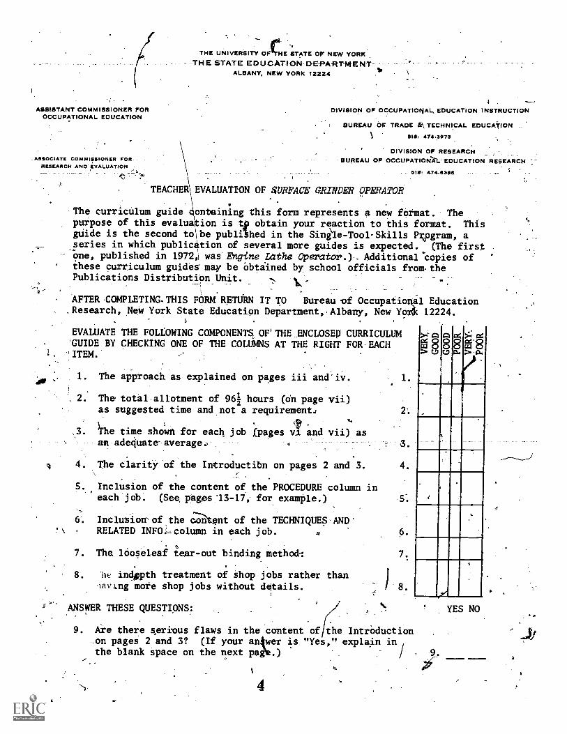
TEACHER EVALUATION OF SURFACE GRINDER OPERATOR
The curriculum guide ontaining this form represents a new format. Thepurpose of this evalua ion is tp obtain your reaction to this format. Thisguide is the second to be publchhed in the Single-Tool-Skiils Pvgram, aseries in which public tion of several more guides is expected. (The first-One, published in 1972,\ was Evine Lathe Operator.)- Additionarcopies ofthese curriculum guidei may be Obtiined by school officials from-thePublications Distribution Unit.
AFTER COMPLETING.THIS FORM RPTU'RN IT TO Bureau 'of Occupatioual Education.Research, New York State Education Department,Albany, New Yordc 12224.
-
EVALUATE THE FOLLOWING COMPONENTS, OF'THE ENCLOSED CURRICULUMGUIDE BY CHECKING ONE OF THE COLUMNS AT THE RIGHT FOR EACH
1,, ITEM.
1. The approach as explained on pages iii and'iv. 1.
2. The total allotment of 96i hours (oh page vii)as suggested time and not a requirement.:
I fhe time show n for each job (pages va and vii) asan adequate-average..
2.
4. The clarity of the Introductibn on pages 2 and 3. 4.
5. Inclusion of the content of the PROCEDURE column ineach job. (See pages'13-17, for example.) 5.
6. Inclusion'of the cl-Rtent of the TECHNIQUE§ ANDRELATED INFO.-column in each job. 6.
7. The looseleaf tear-out binding method:
8. Ile indoth treatment of shop jobs rather thanlavIng more shop jobs without details.
ANSWER THESE QUESTIONS:
7.
) 8.
>-r Cz1c4 8
E,D
9. Are there serious flaws in the content of the IntrOduction.on pages 2 and 3? (If your anAwer is "Yes," explain inthe blank space on the next paee.)
j4
YES NO
11;
t,-
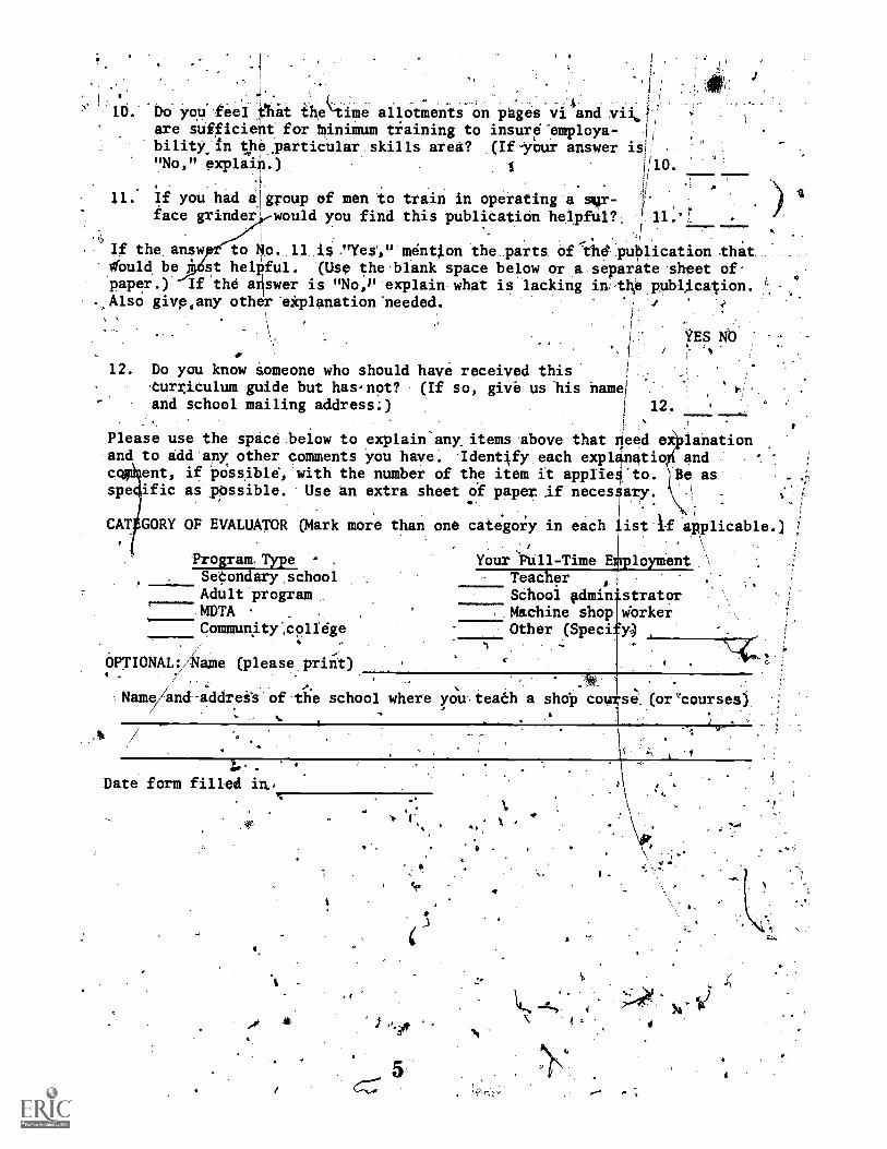
Do you' feel_ttit ihetime allOtiMents-on pages vi andare sufficient for binimum tiaining to insur#employa- I
bility in the particular skills area? (If-your answer is!"No," explain.)
If you had a group of men to train in operating a sgr-
00.
i.
face grinder would you find this publication helpful?.
If the answ to No. 11 i$."YeS," mention the parts of"the puplication thatObuld be st helPful. (Use the blank space below or a separate sheet of'paper.) If the Oswer is "No,P explain what is lacking in-the publAcation.Also give,any other eiplanation'needed.
12. Do you know someone who should have received this1
-Curriculum guide but has-not? (If so, give us his name!and school mailing address;)
! 12.
YES Nb
Please use the space.beiow to explain-anylitems above that ileed eiilanation.and to add'any other comments you have. .Ident4fyeach exp1natioi ind
ent, if ixissible, with the number of the item it appile:to. ascowspe
CAT
ific as pOssible. Use an extra sheet of paper Af necesary.* .
,
than one category in each list10 applicable.)
\. ,\,
Your Full-Time EI:Iployment \
Teacher i ,
Schooi gdmin strator
:y)Machine shop viorkerOther (Speci
GORY OF EVALUATOR (Mark more
Program-TypeSeCondary schoolAdult programMDTA
.
Communitycolldge
OPTIONAL:/kame (please priiit). . s
Agame and-addreit of the school where,CMC
youteaCh a shdp,cou se(or"courses)
3h-
Date form filled in,,
,s
.-
9240040e
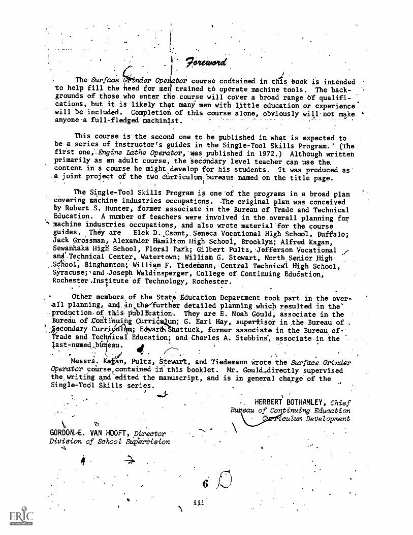
The Surface COnder Ope Ow course contained in this book is intendedto help fill the heed for men/ trained to operate machine tools. The back-grounds of those who enter the course will cover a broad range of qualifi-cations, but it-is likely that many men With little education or experiencewill be included. Completion of this course alone, obviously Will,not makeanyone a full-fledged machinjst.
This course is-the second one to be published in what is expected tobe a series of instructor's guides in the Single-Tool Skills Program. (Thefirst one,.Engine Lathe Operator, was published in 1972.) Although writtenprimarily as an adult course, the seCondary level teacher can use the,content in a course he might,develop tor his students. It was produced as.a joint project of the two durriculum:bureaus named on the title page.
The Single-Tool Skills Program it one of the programs in a broad plancovering machine industries occupations. :The original plan was conceivedby Robert S. Hunter, former associate in the Bureau of Trade and TechnicalEducation. A number of,teachers were involved in the overall planning for
's machine industries occupations, and also wrote material for the courseguides. They are Elek D.,Csont,,Seneca Vocational High Schoel, Buffalo;Jack GrOtsman, Alexander Hamilton High School, Brooklyn; Alfred Kagan,Sewanhaka HigH School, Floral Park; Gilbert Pultz,.Jefferson Vocationaland Technical Center, Watertown; William G. Stewart, North Senior High
,Seliool, Binghamton; William F. Tiedemann, Central Technical High School,Syracusepand Joseph Waldinsperger, College of Continuing EduCation,Rochester,Institute of Technology, Rochester.
Other members.of the State Education Department took part in the over-all planning, and,#thefurther detailed planning which resulted in the'production,of thit Putlfbation. They are E. Noah Gould, associate in theBureau of continuing Curri4 um; G. Earl Hay, supertisor in the Bureau of .
LAecondary Curri' ; Edward% hattuck, former assodiate in the Bureau of.frade and Techycical Education; and Charles A. Stebbins', associate in thelast -named .bt4eau. p
"";
Messrs. Kagan, Pultz, tewart, and Tiedemann *rote the Surface GrinderOperator coUrsecontained idthis booklet. Mr. Gould,directly supervisedthe,writing ancl,edited the manuscript, and is in general charge of theSingle-Tool Skills series.
1
GORDONA. VAN HOOFT, DirectorDivision of School SI:tpervision
-A
0 4.
a
,. HERBERT BOTHAMLEY, Chiefeau of Continuing Education
tculum Development
a.
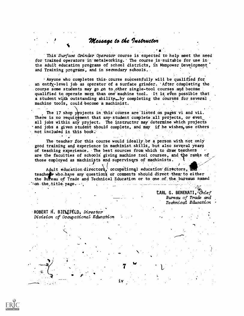
Me4449e ett tie Tosaluectoitir
This Surface alinder Operator course is expected to help meet the needfor trained operators in metalworking. The course is-suitable for use inthe aduli education programs of school districis, fU Manpower Development'and Training progrins, and in secondary schools.
.Anyone who completes this.course successfully will be qualified foran enttx-level jcb as operator of a surface grinder. °After cómpleting thecourse some students may go on to lother single-tool courses and becomequalified to, operaie more than one madhine tool. It is elen possible thata student wi,tb outstanding ability.-by completing the courses for several
-machine tools, could-become a machinist.
. _
The 17 shop p jects in this course are listed on pages vi and vii.There is no requi ment that any-student complete all projects, or evenall jobs within any project. The instructor may determine which projects
-and jobs a given student should complete, and may if he wishes, use othersnot included in this book;
The teacher for this course would ideally be a person with not onlygood training an0 experience in machinist skills, but also several yeargof teaching experience. The best sources from which to di-aw teachersare the faculties of schooli giving machine tool courses, and tbe ranks ofthose employed as mhchinipts and supervisvs of machinists. 1
I
Adult education director ! occupaionial education-directors,teache who.hve any question or comments should direct-them-to eitherthe Bu eau of Trade and Technical Education or to one of_the.bureaus named
--on the, title. page.
ROBERT a. ElImptu, DirectorDivision of Occupational Education
iv
tARL G. BENENATI,4ChiefBureau of lira& andTechnical Education
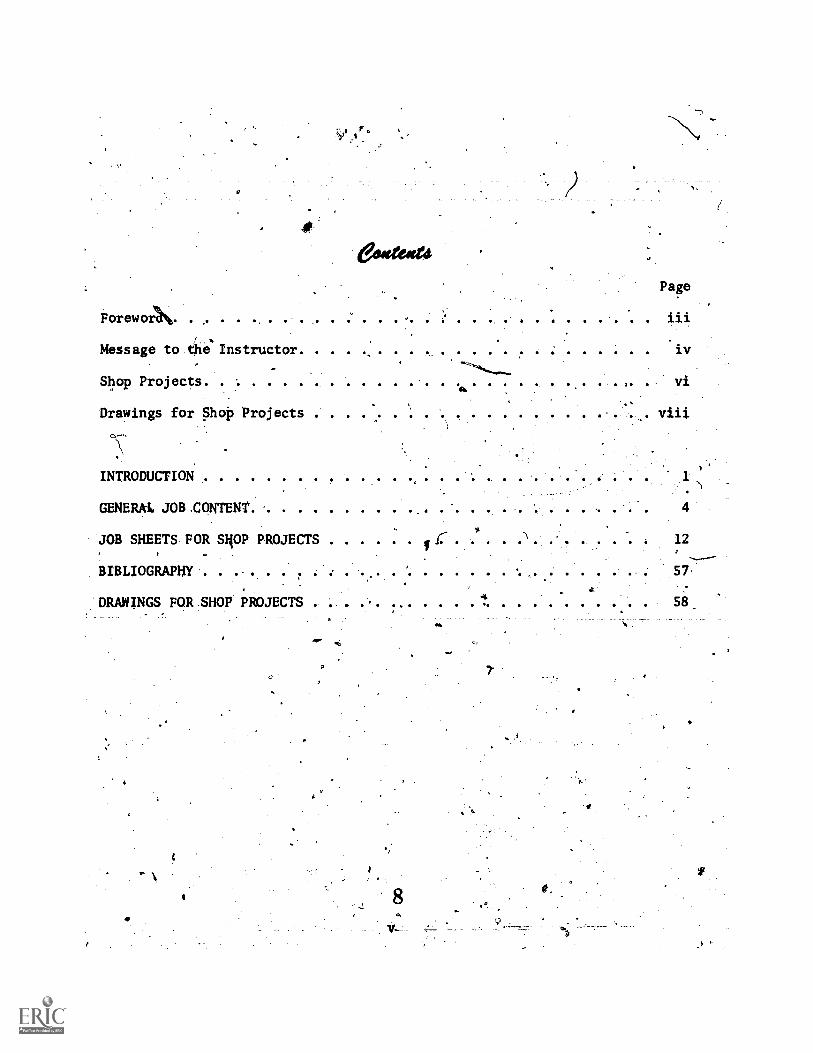
&grog&
Page
Forewo24%
iv
vi
Drawings for Shop Projects . viii
Message tO.the Instructor
Shop Projects
C
INTRODUCTION
GENERAL JOBZONTENT 4
JOB SHEETS FOR slim, PROJECTS . .... 1::'-' . . . . . '' . .1
. 12
BIBLIOGRAPHY,
.57,
:DRAWINGS FOR.SHOP PROJECTS . .. . .. ...4
aAPP.
v---
S.
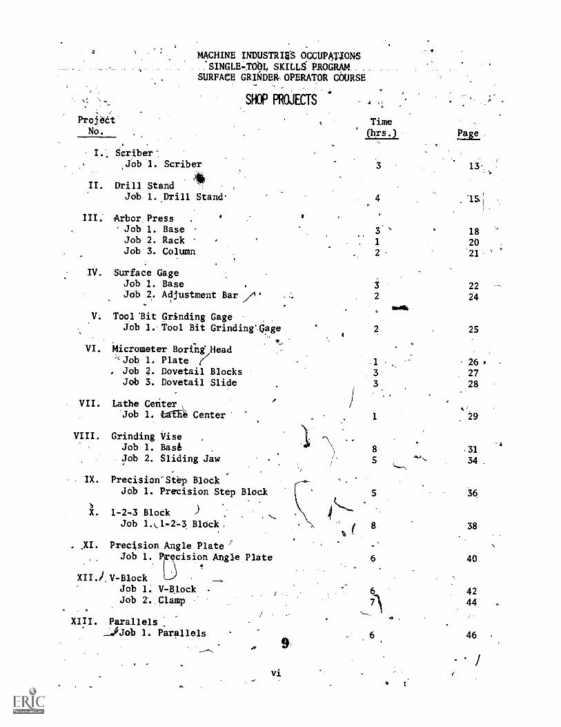
MACHINE INDUSTRIES OCCUPANONS:SINGLErTOOL SKILLS PROGRAM_SURFACE GRADEWOPERATOR CoURSE
. ,
.SHOP PROJECTS p.
ProjedtNo.
I. Scriber',Job 1. Scriber
11II. Drill Stand
Job 1. Drill Stand.
III. Arbor. Press .
Job 1. BaseJob 2. RackJob 3. Column
IV. Surface GageJob 1. BaseJob 2.. Adjustment Bar /3
V. Tool lit Grinding Gage,
Job 1. Tool Bit Grinding'cage
VI. Micrometer Borfng. HeadJob 1. Plate (/
. Job 2. Dovetail BlocksJob 3. Dovetail Slide
VII. Lathe Center\'Job 1. bgfa Center
VIII. Grinding Vise ,
Job 1. BaseJob 2. Sliding Jaw
- IX. Precision-Step BlockJob 1. Precision Step Block
X. 1-2-3 Block ) ,
Job 1.0-2-3. Block,
Time
1121.21
4
3.
1
2
Page
13.
18
20
21
22
24
2 25
.1
33
26 P
27
28
1 29
8 .31
5ft,
34.
36
8 38
. ji. Precision Angle Plate ,
Job 1. ecision Angle Plate 6 40
XII.i.V-BlockJob 1. V-81ock 6
, 42Job 2. Clamp 7) 44 .
-,.,. a
XIII. Parallels_.40Job 1. Parallels
vi
6 46
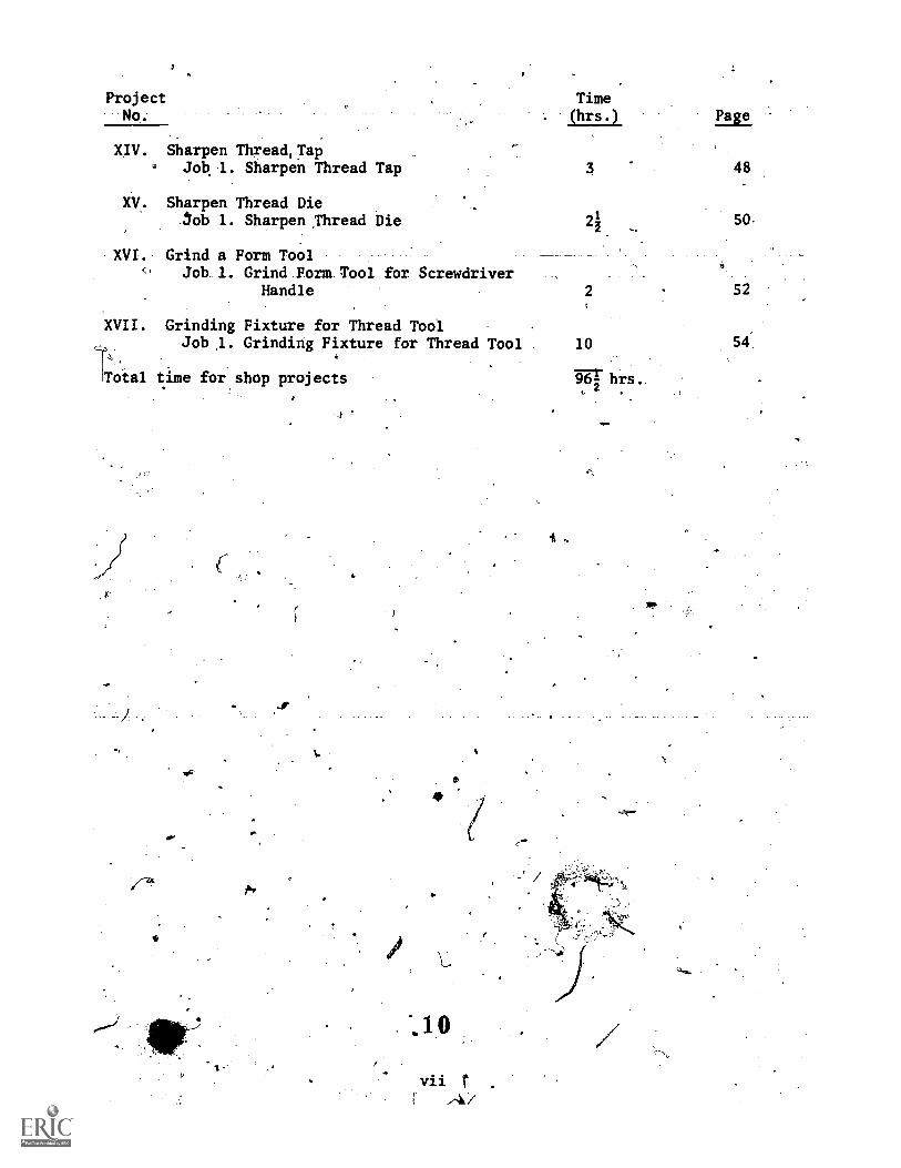
Project Time(hrs.) Page
XIV. Sharpen Thread,Tap. Job 1. Sharpen Thread Tap 3 48
XV. Sharpen Thread Die.3ob 1. Sharpen ,Thread Die 50.
XVI. Grind a Form ToolJob 1. Grind Form Tool for Screwdriver
Handle 2 52
XVII. Grinding Fixture for Thread ToolJob 1. Grinding Fixture for Thread Tool 10
Total time for shop projects
774
600
39-hrs.
-.1
vii r
DWG.
NO.
/Imicrometer22.1 Aerometer22.2 Micrometer23 Micrometer24 Micrometer
I '4.-
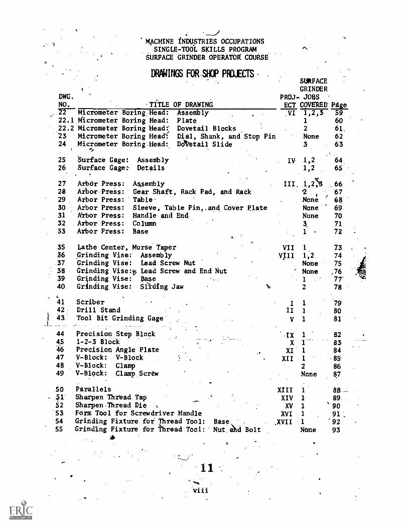
'MACHINE iNDUSTRIES OCCUPATIONSmcp7To4wps. pROGRAM.
SURFACE GRINDER OPERATOR COURSE
DRPRINGS FOR.SHOP PROJECTS
.TITLE OF DRAWINGBoring Head:Boring Head:Boring HeadfBoring HeaeBoring-Head:
25 8urface Gage: Assembly26 Surface Gage: Details
27 Arbor Press:28 Arbor Preis:29 Arbor Press:30 Arbor Press:31 krbor Press:32 Arbor Press:33 Arbor Press:
AssemblyPlateDovetail BlocksDial, Shank, and Stop PinDattail Slide
A4semblyGear Shaft, Rack Pad, and RackTableSleeve, Table Pin,.and Cover PlateHandle and EndColumnBase
a.
35 Lathe Center, Morse Taper36 Grinding Vise: Assembly37 Grinding Vise: Lead Screw Nut38 Grinding Vise:ty Lead Screw and End Nut39 GrOding Vise: Base40 Grinding Vise: Sading Jaw
4142
43
44
4,5
46
474849
50, S1'
52535455
ScriberDrill StandTool Bit Grinding Gage
Precision Step Block1-2-3 BlockPrecision Angle PlateV-Block: V-BlockV-Block: ClampV-Block: Clamp Screw
SURFACEGRINDER
PROJ- JOSSECT COVERED Eige.VI 1,243 59
1 602 61,
None 62
.3 63
1,2 641,2 65
IV
III, 1,27%3
4
NoneNoneNone
1 .
VIIVIII
6667686970
71
72
1 73142 74None 75
' None ,76
1 77'
2 78 :
'-IX 1
X 1
XI 1
XII 1
2
None
79SO81
82
8384
86
87
Parallels XIII 1 88 -
Sharpen Thread Tap XIV 1 89-..
Sharpen Thread Die XV 1 90Form Tool for Screwdriver Handle XVI 1 91,Grinding Fixture foi Thread Tool: Base, . .XVII 1 '92Grinding Fixture for thread Tool:- Nut ahd Bolt None 93
311.
4
-r.
georo4gerefla
ea
12
r
4
4?

,Zi-.. .,
.. c,.As sh64 in the Conteiits, this'Suffacd Grin'den Opgrator,course consi;ts'--.I. -
"of-this Introduction, Geffetal Job Content?(whith'explains wIlat the. operator's,job, irndludes), ShopProfActsv and-the drawingrfor:the proje-ots. The course
. -covers the operation, og, the surf'ace grinder oinly.
1- r ..., $ . I 2- ..:.er,''''.-.
. ), Th 'olijor whic,A the tritinee would' e qualified upon completion of. .-
this cobZ5. is referratb in the Dictio ry5Of decupatidnal Titles (Underthe coda:nutilber 4b3.40) as grinder oper !tbr, surface, tool; grinder, han
-'precisjo grinder,101,face;,, rotary-5urface iiiwieri.skirface grinder;'surfacegrhlder'too l. and guifacelrinding4achine han4..,
"4, -''!47..:.
,g- - ..
. . The'ioneral4objective of-the course.is to fraiu men,.in. a compdYatively, . . .
short time, tobe plaCed,as:Surfice rinder'operitors. `The course is not. intended.to fgiVe a'broad training in metalwqtking,,but oniy the skill'to
op.erate one kind of _metali4orking thabhine.' BY .keetsing, the; okj ecti e narrow,. .
the2trainiNg, time is kept. to a minimum, and the trainees are ma14 available1for.i4brIc Winomt a ileng delay.
. One important purpose,df this course is to'help those with verylittle .7
bickground.,*e pterequisites Or-admission to an adult cburse should be -
operating-authorities lor,tach program, rsiphool, and schdol district halbrodd ienough so none will be bared who cdUld be made emplaYable. The .,
the responsibilqty for determining-the prerequisites for such a course,,and can adapt them to any sliecial local'conditions.
.
,
The minimum prerequisites we suggest for a trainee-(and they are notmandatory) are that he have enough ability to understand.and follow the-coulte instructiOns (either written or orar), so he can,p,oduce the Simplestworkpiece included in the course. Such a trainqualify onlyras a production machine operator, wherare *lade for him. Another trainee with more backgrofor jobs requiring more skill, such as precision SUM'
, perhaps, be able toall the machine setups
will possible gUalifye grinder operafor.
4,..,
We believe that enough general information about th ob and MOD6 than,enduih shop projects are included for the trainee to peac the tener4objective of the course. . All essential surface grinder skills are used inthe .shop projects a.number of times. The schools may use everything in thecourse, they may ipliFfIly some ek the material, they y make changesin it, and they may use o her material dot contained e. They may'alsodetermine the length of the class periods, their frequency, and the total
,
amount of time to be spent in training.. For those that need a guide: A'typical adult night class runs 21 to 3 hours, either once or twice a week,for 30 weeks.
.
..
1.
The drawings in th'is course are part of a serially numbered set beginningwith No. 1, which appears in the Engine Lathet6Verator course. The numberscontinue through the drawings of this course and will be continued further
'in other courses in the Single-Tool Skill
5\F:rOgram to be published later..
1Z
Drawings in this course which are also in th Engine Lathe course arereproduced here with the same drawing number Some drawings appear inthis book which are not needed for the shop projects of ttlis course. They .i..
are included here for the convenience of ke ping together'ill the drawingsof an assembly. Those in this publication un from 22 through.SS of the .
series.
2
1 3
..,....)- . e.
. e _*i 's .
4 44mlas,Cln the drawings all dimensions arg in'ipthts unless oillerwise
7.iridicated.. As a shop projett is Eissignedi to .a student, werecommend tbatthe instructor give hit;.copies of-thfi job sheet.an0 applicable drawings.The- pages of the book shouldbe used as masters for making te copiesneeded? but:they must be.kept clean and should notbe,.used anyone b.
woriing on a mathine. ' 4ol' I / '11 i, o . .,, %
0. .// . . .
E.ach4drawing has four,blocks foknformation if the bottom, with,the..,-one'at the upper right blank. We suggest that-the instrupttarliaxe the
student write the.numbers,of tht project and jOb fol which he it using'tedrawing in that blank Space. Each job -sheet, hat'the words Unit No. in the '
upper.le corner; but.no number is givpn.. The instiuctor may wish to write,..^ a'nUmb inipis-tpace to fit in-witkhis own method of Organizispg his_classroom and'shrofork. 4.
.sNo , -- '')....
Drawing-55 contains tablesjgilring several different sets of dimensions'' for.the workpiecee'pi'etured: 'Mese tables permit trte'instructor to setledtthe set of dimenskons which he,finds hest for.each student or fqr theconditions under WhiCh his cLass'Operates.
,-
Many of the wOrkpieceS on which surface grinding is to be done.in.this*course are thdse produced in other courses in the Single-Tool Skills series,such as those govering milling,, drilling, and Heaetibating. (See pages 15and 20,4for example.) If a given Workpti.ece is not available at the outputof another course in hig shoOrit is. the instructor's responsibility toobtaip the workpiece. He can do this by making it himself oi.by obtaining*it as the output of courses given elsewhere.
The job sheets show two references which are especially recommended.
for the machine work. The bibliography gives the complete citations forthese two books and alsO contains Additional references.
Following are the abbreOiations used in the text aneUrawings for thiscourse.
ACT.ACTG.
ALUM.'ASSY.
CHAM.CBORE.CRS.
CSK.
DIA.
DP.
----actuate
actuatingaluminumassembly'chamfercounteii&recold,rolled steelcounte sinkdiame
\
DP diametral pitchDR.
DR,OR h. ROD drilr rodEQ. SP. equally spacedFAu finish all overHDHDL.HGT.HEX.
4
headhandle -
heighthexagonal
3
14
,
HT.
_LG.
LGT4.MATL.MED.
1.PT.
R or RAD.REQD.
R.H.
. SCR.
SOC.SPEC.SPHER.STL.
SQ.
TYP.
W.
high-speedheightlong .
lengthmaterialmediumpartradiusrequiredright-hand
1\ screwsocketspecificationssphericalsteelsgpere
'typical. width
s4.k.
'711'
I.
40"
CONTENT OUTLINE' TEACHING POINTS AND TECHNIQUES /
. I
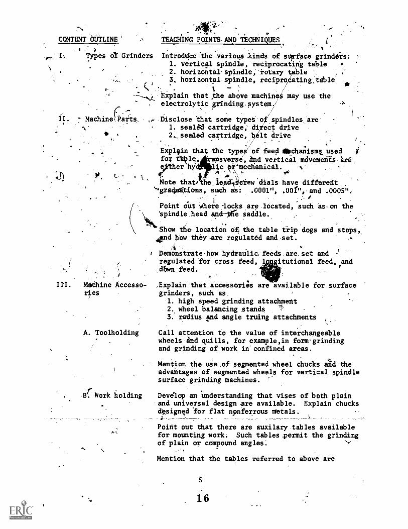
I: Types a Grinders IntrodUce-the-various kinds of strface grindirs: ,
1. vertical spindle, reciprocating table a
2. horizontal-spindle;'rotary able,
3, horizontal spindle, recipro ating,teble- - /
.---7---,.& EXplain that ,the above machineS may use theelectrolytic grindingssystem./
-'7. ..
/
/
I 7 Machine1.Parts, . . Disclose that some types of spindles_are
1. sealed cartridge; direct drive. 2seadad cartridge, belt driVe
Explgin that the types/of feed alichanismk used i
for-thOlec, aasverse,4d vertical mOvemenis ire,efrtherhydli,c. mechanica1. 1
...
A
Note thatithe,lead'T erew dials have differedtgra4oftions, such ei: .0001", .00f", and .0005":
.
MaChine Accesso-ries
A. Toolholding
. 1
Point out where -locks are located, such as.on thespindle head and-11 e saddle.
Show the. location of the table trip 'dogs and stops,dend how they -are regulated and set. -
DeMonstrate.how hydraulic,-feeds.are. setrigulated'for cross feed,'1_Awn feed.-
and.
itutionai feed, and
,Explain that accessories are available for surfacegrinders, such as..
1. high speed grinding attachment2. wheel balancing stands3. radius and angle truing attachments
Call attention to the value of interchangeablewheels.ind quills, for example,in form'grindingand grinding of work in'confined areas.
Mention the use .of segmented wheeladvantages of segmented wheels forsurface grinding machines.
Work holding Develop an understanding that visesand universal design are available.designed for flat nonferrous metals
chucks and thevertical spindle
of both plainExplain chucks
Point out that there are auxilary tables availablefor mounting work. Such tables permit the grindingof plain or compound angles-.
Mention that the tables referred to above are
16
'CONTENT OUTLINE TEACHING FOINTS.AND TECHNIQUIS
F.4
.
available-with angul1--ar graduations,
or sine table-provisions;,and*ay be equipped with mageetic,
, chucs.-
Explain that there are other work holdin devicesavailable*,such as. indexing centers, fi tires,i/steel angle plitetfand V-blocks.
'Pant out that there are various types of miinetictxhucks,"such.es pepmanent and electromagnetic, andthat they are eitheereotangular or round.
°IV. ^cutting Tools Sta ,that sope of thejgrinding whdel abras'ves>
_.
divone, alUminuth oxide; and silicon a cde.- \ .
a MP'point out that-there AT standard shapes ofgrinding wheels, for example
1.. type 7,,wheel recessed on both,Ades,4 2: typej, plain straight:wheel
Further discuss'the composition,of gandingwheels, including -4,
1. grit size -*
2. bonding ma,terials3. structure4. grade.
Call attention to the fact that grinding eelsare Sited by hole diameter, width of face, andoptside diameter.
i
Demonstrate the proper procedures. for mout, ntinggrinding wheels, such as disk type-wheels, dia-mond Wheels, end plain wheels.
Show how large" diameter wheels can be balanced,using a balancing stand. Indicate that somegrinding wheel spindles have a built-in balancingsystem.
Emphasize that for wet grinding.you should allowthe coolant to flow on the wheel when dressing.When grinding is done dry, the wheel must be,dressed dry: Mention that manufdcturer's speci-fications for dressing diamond wheels.must be.obserVed.
-
Interpret the meaning of diamond wheel terMs, sulas conaentration, bond, and grit size.
Ad,
Discuss the differences in dresskng, truing, andshapihg grinding wheels by-various methods.
6
17
-;
CONT OUTLINE TEACHING POINfS AND TECAAIQUES
Differgeibetiftea the: vaiious types of wIleeldresser ,andrtheir application. Present as
exampleit
-IAi \
1. r ive wheels or sticks A2. mechanical precidion dressers,3. diamond wheel brake'dres;ets /
state the importance of truing a ond grinding
wheel with an indicator.
Explain the principle of crush whbel,dreqsIngwhen appliektogfbrm grinding. Elaborate on somrelated items-Inch as
1. crush wheel size and composition411" 2. gtinding wheel types
3. speeds andureeds for' crushing or'grindiing
..turnish grinding wheel selection chirts and show.116w:they are applied in the selection cffs.:grinding wheel fpi a particular grinding problem.
A.V. , Measurement and,. List and ekplain.,the various types allessuking
Inspection , tools. Suggest that these could include
,.
_microietkis,(calibrated.in .0001"); indicators,
%comparators; ancrprofifoieters. -. 4
a .
s. Call Attention to the fAct,that optica1 compara-tors are aVailable in various degnifications,'for,-example, 10 power and ,50 powei.
,
VI. Blueprint Reading fntroduce and cover ail liecessAy blyppiint e,âing.
ForJox1141e .
1. theory of orthogralihic projection2. language of lines3.. sectional.views4. tolerancesS. symbols
N1I. Speediand Feeds Define the'meaning of stir speed. in relationto grinding wheels. biscuss 'proper crossfeed
4
, rates tor rough and finish grinding.
/Consider and compare the depth of cuts that mayf be taken.on vertical spindle MacIlinis and hori-
zontal spindle machines.
Continue by'explaining.how longitudinal r rtarytable-petesis-will-affect-grincting-wheel -wear,
surface finish. .
Discuss the fact that the.aiount of contact areaon the workpiece determines wheel composition
1 8 AL
CONTENT OUTLINE
4.
TEACHING POINTS AND TECHNIQUES
selections. This affects Maness, grit size, andstructure.
tht rotary grinders have variable tableand in-feeds.
,
VT. Tiede Mathe- Introduce and Over all nbcessary t de mathematits,.:f
f1
,
such %4 1. s*fate speed forAulas
2. r.p.m.'formuras , t.
, ;I... trigonometric fuRftioni
IX. Coolants PreAent information efijing ithe 'use and kinds of ,.'cutting fluids.am'i tb4 sired advantages of thecutting fluids, as high,cutti/ig speed,Igoodsurface' finish', and longer tool life.
V--'_t_Estab that somer fUnctions of cutting fluius
are ricating, cooling, and antiweldin.g.
Point out where dee cpol t flow should be directed.in relationjo the Work d grinding 'wheel.Continue Wexp *ning theç dirty coopult wirtffect the surfa e-finish y leaving scratch marks
% on thelob% ...
..
Explhin the ratio of water. ;fi,soluble oil concen-trate in mixing soltble coolhts.
Tell about directing coolant flow by some methods.;such as spray mist flush ,(lood), and th.ough thewheel. .
Care and Main- Provide some information concerning the opre andmaintenance of the type bfourface grinder in use,ctivving
1:Ntleaning of machine2. cleaning of chucks3. mounting of wheel sleeves4. making machineadjustments
.
Utilize the standard operations and repair'manualfor maintenance information on the grinderNin use!It includes, for example, thbrication,*0 howthe wieel. spindle is removed.
stqielth4 thec.944nT_filter must be kept cleanto Obtain goo41,, Coofant\ flow and good finishes on
J work surfaces. 10
Cite the procedures or resurfacing a magnetic0
chuck. Include the method of checking the chuck
tenance
,1. r \,
,118
;

CCNTENT OUTLINE
.XI: Safety
TEACHING POINTS AND TECHNIQUES
, for aciiracy with ail indicator.
Show how the guide rail ds ground parallel wq.hthe w rk table and demonstrate how .t heck itwith an indicator.
4
Note that magnetic chpcks not in shou d bethroughly cleaned and'greasea'to p otect themagnetic poles from dirt and möi,stuje . Mentionthat light"burrs on magnetic cies can beremoyed by_han1d stoning. 4,
'
Ihtroduce thef following safe working practicesoperating griftding machines:
1. Wear cl e fitting clothes.2. Wear safety,glasses.3.,Make sure all guards are in...,place.4. Keep hands away from movinepart.S. 'Knowhow to operate the cont
for
Discuss particular dangers'.the :surifte grinder,'40
1. Makute 'that the\, the. ngnet.: iBidoCk
tll Mecos.. :
A1e104te::,thet::the4.
mounted and haa nei flewheel is
'cracks in t.3. Never attempt to cle-
1
.419ra tic ch ck4or mo4t-or remoVe wo 1nless he whiklis, ownogLthe way Y4'
, 4. Alwaysffiserve th ding end dressingactions4rem thio t-hand side of,themachine#46 avoid fIying,particles.
S. Know that the wheel c rs the work beforestailing.the grinder'
6. Be sure that you know the safe bperatingspeed of 'tbv wheel y u are using. w .
Expla 11 tertha which are pertinen;Whlthis,unit of the course, such hs sparking out,glazing, hd loading.
XII. .Trade TermS
XIII. Operations
A. Grinding flat Show how to properly place material on the magnetic'surfaces chuck to grind a flat surface.
Point.out that long thin piedes of work are bestset diagonally-across the,chuck,..and that alter-nately turning the piece over and making light'"cuts wil,reduce the chance of warpage due Wheat.
20 .e
. _
CONTENT OUThINE
B.
TEACHING POINTS'ine
TECHNIQUES
Demonstrate how to tug gnetic parallels on aicise when grinding wo piece of unusual shape.
'P,ara lel 'sur- Exp ain thed work can be ground parallel by,face grinding ious methods, s as
1. holding direc on the magnetic chuck2. holding in a:gr1ning vises
Ns. 3. clamping t'erFan an le plate4. using doul?, Asking tape
C. Grinding 70.square,
D. Angular°grinding
E. Form grindci)
ide'grinding
G.---,Cutoff -grind-ing,
H. Cylindricalgrinding
Mention the use of magnetic parallels Ahat are-set on the magnetic chuck, ground parallel, and'then used as the surfIce for niounting work.
akTell About the pro edure for t guar g relitanguirdrpiece-1p of work ng precision grinding Vises,angle platee, and s,quarilfgr fixturtit .
Caution the students to remove all burrs.bipsforemaking the° next setting ott frol-d.tnudevici.
Me ion, the use of a V.-block...for gtinding the enda round piece of work sqpare.
Suggest rat the f holding devices may beused to rind angula surfa * fixture,, toolLma4er's vise, magnetic sine and angle .
. p 1,ate
Explain that conTo angles are ground 'by the-use of a compound tar table equipped with amagnetic chuck.'
Discuslevices for form dressing a grinding wheel,such as ,
l. radj.us and angle wheel dresser2: template for6 dresser3. opti'cal form dresser4. crush- form dresser
Continue by statine that there are two types oftemplate form dressers:f those mounted on thespindle and those mounted on the table., -
-
Demonstrate_how side walls can be ground by under-cutting the sides of the grinding wheel.
State thiit hardened-steel part§--are -usilly -cutoff by using a resonoid or rubber wheel.
Point out that it is possible to do cylindricalgrinding operations by mounting an attachment
CONTENT OUTLINE TEACHING POINTS AND TECHNIQUES
I. Iniernal ,
grinding t '
designed for this type of work.
Discuss various operations that fan be performedinternally by the use of 'the hig1 speed surfacegiinding attachment. These incli.Ie
1. grinding slqs and surfaces hich,do not---1-'-permit the use of awlarge w el2..grinding internal radii3. blending radii to an angular Oestraight
'plane
Show-.'bow the fixture, quills, and grindingare mounted.,
J. Cutter ,Sta.te that cutter grinding is done on the surfacegrinding 4' grinder. Mention tge following, examples: --
1. form grindiag.lathe'tools :
. 2. grihding_tools for turret lathes3. ginding milling outters (with attachment)
Continue by showing that tools such as taps,reamers, and form cutters can be grOund usingindex centers.
r .
I.
2
11
I.
2312
Unit No.
Pr4ect I
Job No. 1
Brawina No. 41,
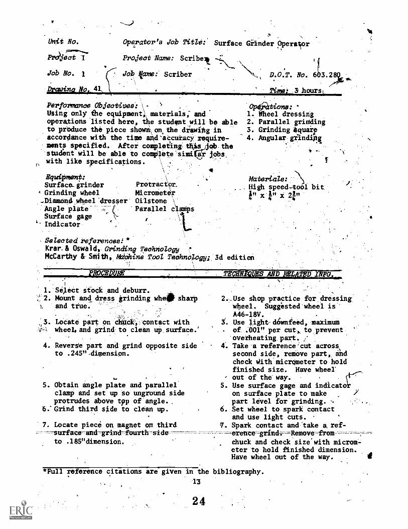
Operator's Job Title:
Project Name: Scribelt
Job lame: Scriber
Surface Giinder Operattor
Perform:me Objectives: - .
Using only the equipment,, materials; andoperaXions listed here, the studantwill be ableto produce the piece shown\ on.the diawihg inaccordance with the time and'accutacy require-meets specified. After completIng thiA)job the'student will be able to comfilete sim4ay lobswith like specifications. \ .
\
\
Equipment:Surface-grinder Protracipt.
A Grinding wheel Micrometer...Diamond wheel-dresser Oilstone:Angle plate.Surface gageIndicator
'Parallel c,aMps
D.O.T. No. 6193.28$c
Time: Shourst
01016tions:1. Wheel dressing2. Parallel grinding3. Grinding tquaip4. Angular gilnang.
Materials:High speed-tool bit
x et" x 21"
Selected references:*Krar.& Oswald, Grinding TechnologyMcCarthy & Smith, *chine TooZ Technology; 3d edition
PTCEDURE
1. Se,lect stock and deburr., 2. Mount and dress grinding wheat sharpt and tfue.
,3. Locate part on Chuck, contact withwheel, and grind to clean up surface.'
4. Revers'e part and grind opposite sideto .245"-dimension.
S. Obtain angle plate and parallelclamp and set up so unground sideprotrudes above tpp of angle..
6: Grind third sj.de to clean up.
7. Locate piece on magnet on third=surface-and-grind -fourth-side-
to .185"dimension.
TECHNIQUES AND gym INFO.
2..Use shop practice for,dressingwheel. Suggested wheel isA46-18V.
S. Use light-d6wnfeed, maximum- of .001" per cut, to prevent
overheating part.4: Take a reference'cut across
second side, remove part, andcheck With micrometer to holdfinished size. Have wheel'
- out of the way.S. Use surface gage and indicato
on surface plate to makepart level for grinding.
6. Set wheel to spark contactand use light cuts. '
. Spark contact and"take a ref----erence-grindr- ---Remove-froar
chuck and check size with microm-eter to hold finished dimension.Have wheel out of the way. I
*Full reference citations are given in the bibliography.
13.
2 4
PROCEDURE,
I ,
ff. ObtairL angle plate ind clamp, thenset up workpipce to grilid sharp.edge to a 650 angle.
9.', emove burrs *With stone,and submitfor inspection and grade.
."
4 0
r*.
/
n,
se
TECHNIQUES AND RELATED INFO.. -
g. Block the work with'parallelblocks to hold securely, and
. use very light finish togrind sharp edge at 65°-angle.
2 5
14-
7N1. _
.ce-e ;z1
4
Vnit NaY
Project II
job No. 1
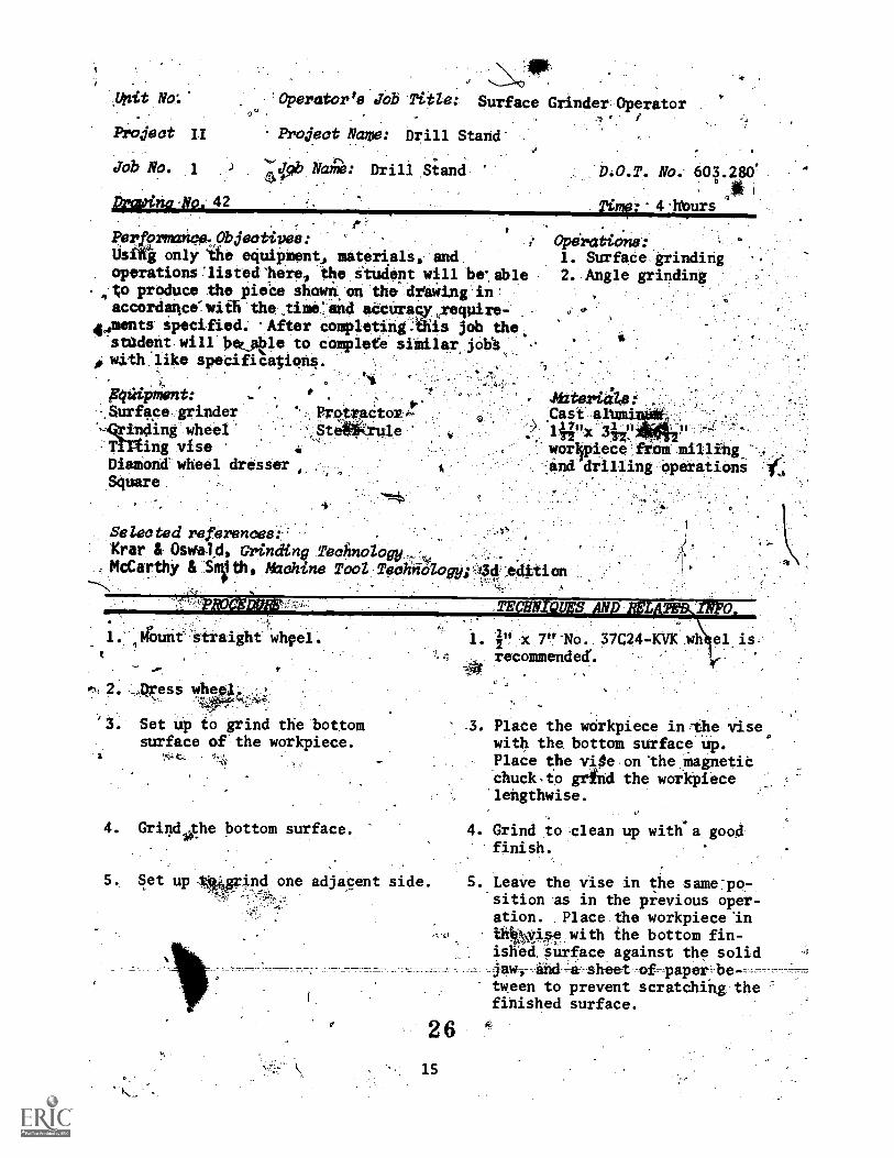
Operator's' Job Title: Surface Grinder OperatorT. /
Project Name: Drill Stand'
NaAol: Drill Siand
preen° Na. 42
Performance.Objectipes:Usifig only the equipment, materials, and
operationslisted'here, the itudent will brable..to produce the pieCe shown on the-desWing in
accordamce-with the .time*and accuragy,require-4aments specified. 'After completing.tlis job the
stadent will beefitle to complete similar jolia0 with like specification.l.
gqiipment:%Surface grinder
mding wheeling vise
Diamond wheel dresserSquare
D.O.T. No. 604.280'
' 04*4 lfturs
Operations:1. Surface grinding2. Angle grinding
p.'LP-rotViCtok:,--'St4SCrale
AzteriaZ0:- .
Cast'iwx iiiistitt
worlipiece fiom millithg
and drilling operations
Selected references:Krar & OsVald, Grinding Technology-At,.
-
McCarthy & Smetb, M2ohine Tool Technology;'.13dedttion--\
rA,
; 01:
. ,Aunt-airaight
TE' 0
,,Qxess Whee
. Set up to grind the bottomsurface of the workpiece.
4. GrindlAhe bottom surface.
. Plate the workpiece in-the vise,with the bottom surface up.Place the vite on the magneticchuck,to grind the workpiecelengthwise.
4. Grind to clean up with a goodfinish.
5. Set up 444prind one adjacent side. 5..Leave the vise in the same-po-sition as in the previous oper-ation. Place the workpiece'intbkVise with the bottom fin-
26
1 5
ished Surface against the solidj-aw, _a sheet -ofpaper be-----tween to prevent scratching thefinished surface.

pRcicituRE.
6. Grin4 the aqadent side.
7. Set up to grindione end.
8. Grind the end.
TEcorpss AND:RELATED INFO.
On all setup operations thatfdllow,place a gheet of papbetween eadh finished surfaceof the warkpiece and the vise.
6. Grind to crlean up with-a goodfinish. .
7. Leave the visOin. siti9n ns:41 tit! Orev1.611P.Orlr'.*
ation. 1)1ace.th.e..PrkWO-n.end w.ith the4ini0Pqt0nif..1,, ,
'surface agaifist: the Soli,* ja*,and the finishedYSide'surface.at right 'ankles tO the surface
co of the magnetic chuck:
-9% Set up to grind-the other.end.
Grind the end.
8. Grind to cleatirup with a goodfinish.
,
4
9 Leave the vise.in SAM, po-sition as in the PreVions, oPer-ation. Kace the,finithed end,of the 'workOlece'down in the -
yise:with the'bottomi Oftheworkpiece against-the solic(jaw.
,
Orind to the-averalLaength of6". Dress the wheel' ,when-nec.:
k4essary to obtain a goodlinish.
11. Leave .the vise in the siMe po-'sition.,as abOve.,^, Place the
ottom of the workpiece againste solid jaw with the finishedide down in,the vise.
12. Gr nd to a width of 3".
13. Leave the vise in the same po-sition as above. Place theside of the warkpiece against
*411/4`'f
the solid aw wi th'th e top sur-l
ace up.
.14. rind td an overall height of
15. Leave the workpiece in the sameposition as in the preceding step.Tilt the vise to an angle of 450
11. Set up to:grind the.unfinishedside surface.
12. Grind the side.
13. Set uio to grind the top suiface.
e
14. Grind the tOp surface.
15. Set up to grind one long bevelededge.,
PROCEDURE TECIINIOE'S-4ND kELATED IlVFO.
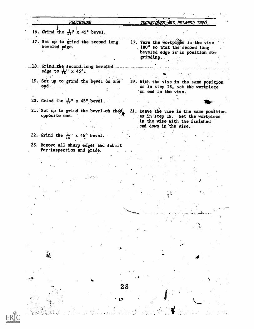
16. Gtind the ye x 45° bevel.
17. Set up to grind the second longbeveled edge.
18. Grind the second, long bevela.edge to x 45°,
19. Sit up to grind the bevel on oneend.
20. Grind the A" x 45°.bevól.
21. Set up to grind the bevel on thopposite end.
22. Grind the x 45° bevel.16
23. Remove all shaxp edges and submitfor-inspection and grade.
446,-vs,
17. TUrn.the workpi44 in-the vise.180° so Mit the-.secondlong,beveled edge i-n position:forgrinding.
.
19. With the vise in the same positionas in step 15, set the workpieceon end in the vise.
lop
21. Leave the vise in the same poiitionas in step 19. Set the workpiecein the vise with the finishedend down In the vise.
'Unit N.
Project III
Job No. 1
powina Noe. 27.33
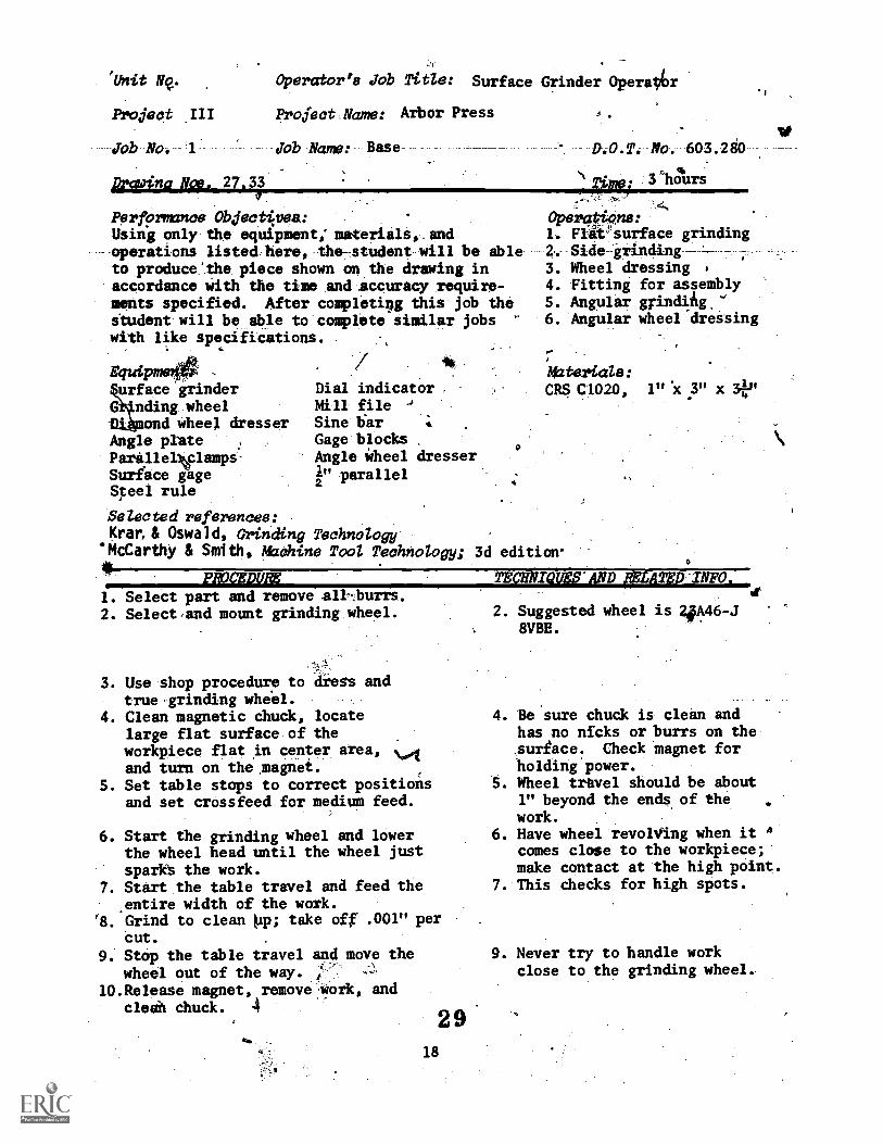
Operator's Job Title: Surface Grinder Opereptr
Project Name: Arbor Press
Job Name: Base D.O.T. Po. 603.280
. 44.
Time: 3 hoursA -114
Performance Objectivea:Using only the equipment; materials,_andoperations listed here, the-student-will be ableto produce'the piece shown on the drawing inaccordance With the time and accuracy require-ments specified. After completin this job thestudent will be able to complete similar jobs '
with like specifications. ,
Equipmeurface grinder
G nding wheeland wheel dresser
Angle plateParallelvlampsSurface gageSteel rule
Dial indicator ,Mill fileSine barGage blocksAngle Wheel dresserI" ymrallel
Operations:1. Fliesurface grinding2. Side grinding3. Wheel dressing4. Fitting for assembly5. Angular gyindiAg,'6. Angular wheel dressing
Materiale:CRS C1020, 1" X 3" x
Selected reftrences:Kran& Oswald, Grinding Technology
'McCarthy & Smith, Maahine TooZ Technology; 3d edition.
PROCEDURE'
1. Select part and remove all...burrs.2. Select,and mount grinding wheel.
3. Use shop procedure to dress andtrue.grinding wheel.
4. Clean magnetic chuck, locatelarge flat surface of theworkpiece flat in center area,and turn on themagnei.
5. Set table stops to correct positionsand set crossfeed for medium feed.
6. Start the grinding wheel and lowerthe wheel head until the wheel justsparkt the work.
7. Start the table travel and feed the,entire width of the work.
'8. Grind to clean pup; take off .001" percut.
9. Stop the table travel and move thewheel out of the way. I--
10.Release magnet, remove work, andcleah chuck. 4
2 9
0.01
18
TECHNIVISS AND pnitTsa-INFO,4(
2. Suggested wheel is 4#A46-J8VBE.
4. Be sure chuck is clean andhas no nicks or burrs on thesurface. Check magnet forholding power.
5. Wheel travel Should be about1" beyond the ends of thework.
6. Have wheel revolving when it °comes close to the workpiece;make contact at the high point.
7. This checks for high spots.
9. Never try to handle workclose to the grinding wheel.
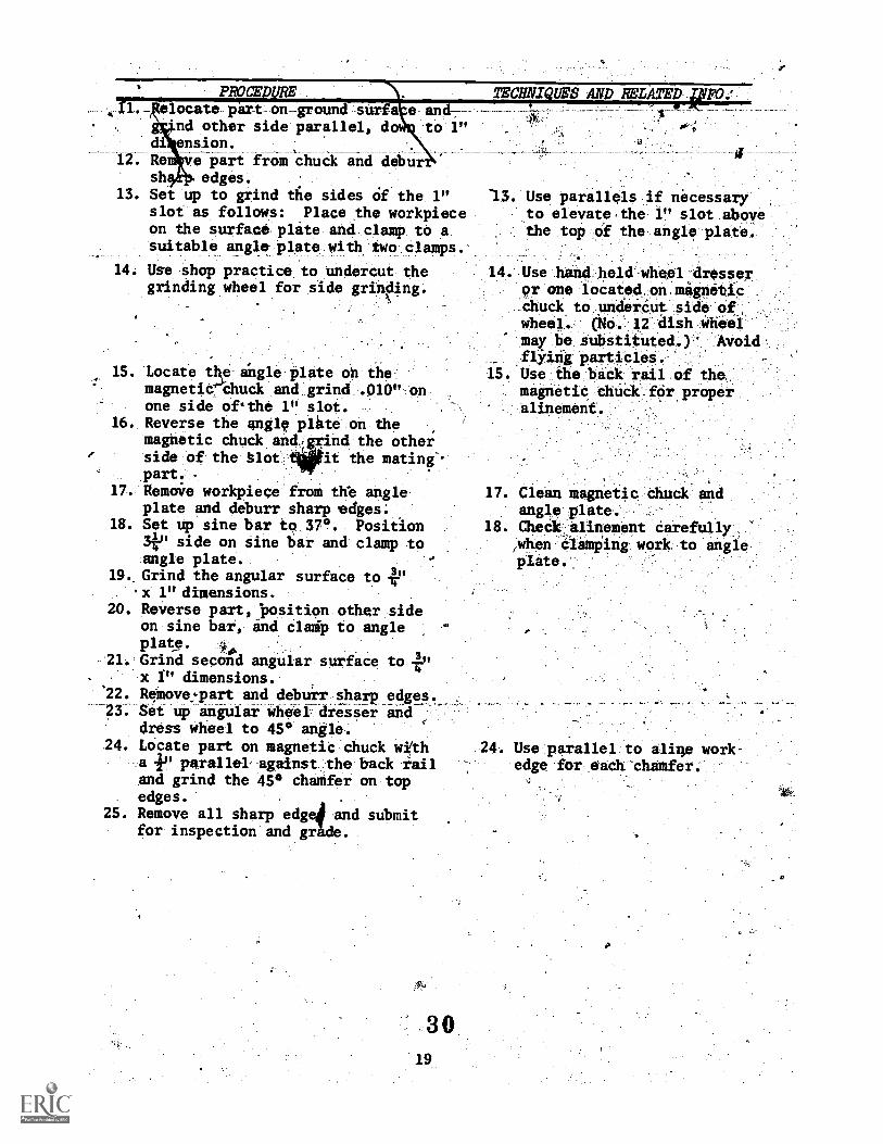
PROODURElocate part on-ground surfs e and*nd other side parallel, do to 1"
di ension. i.12. Renve -part from:Chuck and debur
sh edges.13. Set up to grind the sides Of the 1"
slot as follows: Place the workpieceon the surface plate and clamp to asuitable angle plate with two clamps.
14. Use shop practice to undercut the 14.grinding wheel for side grinding.
TECHNIQUES AND RELATED-alFO
.
13. Use parallels if necessaryto elevate,the 1" slot abovethe top of the angle plate.
15. Locate the angle iilate oh themagnetie:Pchuck and grind .010" onone side ofithe 1" slot.
16. Reverse the angle plate on themagnetic chuck and;grind the otherside of the blot leit the mating-.part. .
17. Remorie workpiece from the angleplate and deburr sharp edges;
18. Set up sine bar to 370 Position3.i." side on sine bar and clamp toangle plate.
19.. Grind the angular surface to 41'.x 1" dimensions.
20. Reverse part, "position other sideon sine bar, and clad') to angleplate.
21. Grind second angular surface to 41,,,. x f" dimensions.'22. Remove.Tart and debuir sharp edges.-23. Set up angular wheel dreiser ind
dress wheel to 45° angle.24. Locate part on magnetic chuck with
a 4.' parallel against the back railand grind the 45° chamfer on topedges.
25. Remove all sharp edge! and submitfor inspection and gr de.
15 .
Use hand.heldwheel dresser9r one located,on.mignetic
dhuck to.undardut side ok,wheel. (40. 12 dish Wheel'
mey be. substituted.) Avoid'
flkifig Pericles.Usethe back rail of the,magnetic thick.fOr properalinement.
17. Clean magnetic,dhuck- andangle plate. -
18. Check alinement Carefully,when Cliftiing work to angleplate._
3019
24. Use parallel to aline work-edge for each chamfer.

/Mit No.
Project III .
Job.A. 2
Drowinape. ;748
PerformInce-Objectiveer-Using only the equipment$i materials, andbperations listed hereohe,itUdent will able
( to produbi the piece sjioWn on the drIwing inaccordalp with the time and dtarratrequire-scuts specified. After completing, job thestudent #ill be able to complete skwi,lar jobswith like specifications. ")
.)"Equipment:SurfacegrinderGrinding wheelDiamond wheel dresser1" micrometerMill file
I.
Operator!a dolajfitle, Surface Grinder Operator
Projedt- Name- r ArboTt 'Press-i
job Mame: Reek .1
I
,
. ;
D.O.T. No. 603.280
;rims: 1 hour
Opersations:
1. Wheel dressing2. GFinding parallel
hhteriale:
C1020, 41." x 1" xpiece ribm milling machineoperation-
Selected references:Krar & OsOiald, Orinding TechnologyMcCarthy & SmWj, &whine Tool ,Technolagy 3d edition
1. Select part and remove sharp edges.2. Dress grinding wheel .sharp and true.
3. Locate part 'bh Magnetic -.Chuck ahdgrind first side to clean up 7 "dimension.
4. Locate ground surface on magneticchuck and take a reference grind.
S. Grind part to +6" dimension.
6. Remove sharp edges and submit forinspection and grade.
31
. Wheel-::23A4648VBE ii recOMMended..Utethop pribtice for,.dressingwheel. ::: ..'. ,-... .'..
lo-.. Chebk tagnetici,aucIcloT nfcks7.----
.. or burrs,:-.,
4._CheCk iizeZwith,miCrometerloesfibli'h amount7to grind forfinish- .
S. This.lif'. art,will be'used it a .
gage to finish grind the: columnslot foiasseMbly.
Ohit No.
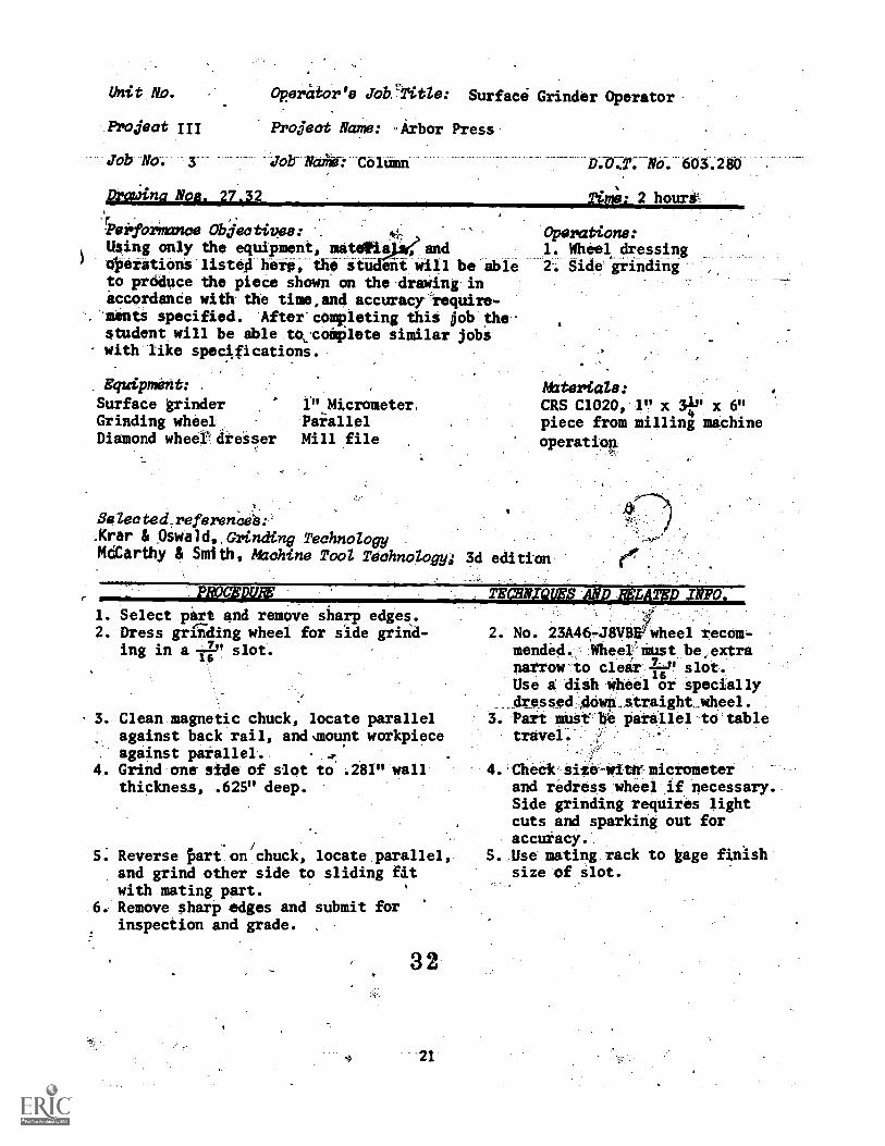
Poject III
Job No. 3
DratAna Nom. 27.32
'iWiTormance Objectives:Using only the equipment, matins endeperations listëHheip , the st- ent will be ableto produce the piece shown on the drawing inaccordance with the time,and accuracy require-
. ments specified. After completing this job thestudent will be able to,coiplete similar jobswith like spectfications.
Equipment:
Surface grinderGrinding wheelDiamond wheef dresser
Operator's Job'TItle: Surface Grinder Operator
Project Name: Arbor Press
Job NaMe: Column
1".Micrometer,ParallelMill file
Selec ted_reference-s:.Krar & Oswald,,Grinding TechnoZogyMearthy & Smith, hUahine Tool Technologyi
D1.6c1: No. 603.280
Time: 2 hours'
Operations:1. Wheel dressing2. Side grinding
Materials:CRS C1020, 1" x 3f," x 6"piece from milling machine
operatiop.
3d edition
PROCEDURE'
1. Select part and remove sharp edges.2. Dress grfiding wheel for side grind-
ing in a -rp' slot.
, 3. Clean magnetic chuck, locate parallelagainst back rail, andsmount workpieceagainst parallel.
4. Grind one side of slot to .281" wallthickness, .625" deep.
7
5. Reverse Pirt.on/
chuck, locate.parallel,and grind other side to sliding fit.with mating part.
.6. Remove sharp edges and submit forinspection and grade.
32
TECHNIQUES AND IFKIND
2. No. 23A46-J8VB#1wheel recom-mended. Wheel must be,extranarrow to clear if slot.Use a dish wheel or specially
_ dressed dowp straight_wheel.3. Part must be parallel to table
travel.
4. Check size-with-micrometerand redress wheel if necessary.Side grinding requires lightcuts and sparking out foraccuracy.
5. Use mating rack to gage finishsize of slot.

k Unit No.;
Project IV
job No. 1
Drawing N08. 25,26
Osrator's Job Title: Surface Grinderl Operator
Project Name: Surface Gage
Job Name: Base .0.T. No. 603.280\
!NM: 3 hours
Performance Objectives: Operations:Using only the equipment, materials, and 1. Wheel dressingoperations listed here, the student will be able 2.-Wheel Mountingto producqi.the piece shOwn on the draWing inaccordance with the time and accuracy require-ments specified. After completing this job thestudenrwill be able to complete similar jobswith like specificationst
Equipment:
Surface grinderGrinding wheelsDiamond wheel dresser
micrometer calip'erAngle plate
V Steel rule
Parallel ClampsSurface plateSurface gageIndicatorProtractor
Selected references:Krar.8 Oswald, Grinding TechnologyMcCarthy 8 Smith, AUchine Tool Technology;
3. Grinding parallel4. Grinding square5. Side grinding6. Angular grinding
tr
Materials:
SAL 1020,piece from millingmachine operation
3d edition
PADOEDVRE
1. Select part and reMove all sharp 1.
edges.
2. Dress grinding wheel sharp and true. 2.3. Locate part on magnetic chuck ,3.
on side surface and grindto clean
4. Locate part on ground side andgrind opposite side to 1.000".
S. Mount part on angle plate withbottom surfaPe abbie the top ofthe angle plate.
6. Grind bottom surface to clean up'to a good finisit
7. Remove from angle plateo locate on- magnetic dhuck, and gri.44 top sur-face to .940" dimension.
-8. Locate on. angle plate at 15°angle and grqd first angularsuirace to 1" dimension from end.
9. Relocate p on angle plate at15° angle and grind second angularsurface until a .440" dimensionis attained.
3322
TEOHNIQUES ANDIELATED INFO.
Use part from milling machine.
No.,23A46-J8VBE wheel recommended.Clean magnetic chuck beforesetting up work; remove any burrsor'nicks.
5. Level surface with indicator aridclamp securely without distortingthe milled slot.
8. Use a protractor to set part atcorrect angle and clamp securelywithout distorting slot.
v
PROCEDURE
10. Remove all sharp edges and locatepart on magnetic chuck in linewith back rail.
11. Mount and dress grinding wheelfor side grindint.
12. Grind one side of slot to .270"dimension .680" deep.
13. Reverse part on magnetic chuck;finish grind second side of slotto .460" dimension to fit mating)part.
14. Remove all sharp edges and submitfor inspection and grade.
c,
34
23
TECHAVIES AND MUTED INFO.. o
4,10: Use paralle,1 to locatework toward center of-ehuck.
11. Use a,No..12 401 wheelor redusamthe wdilth of a41), stralgft wheeVandundercut.the sidO.Wheel 23,446-J8V8EArécoiMended
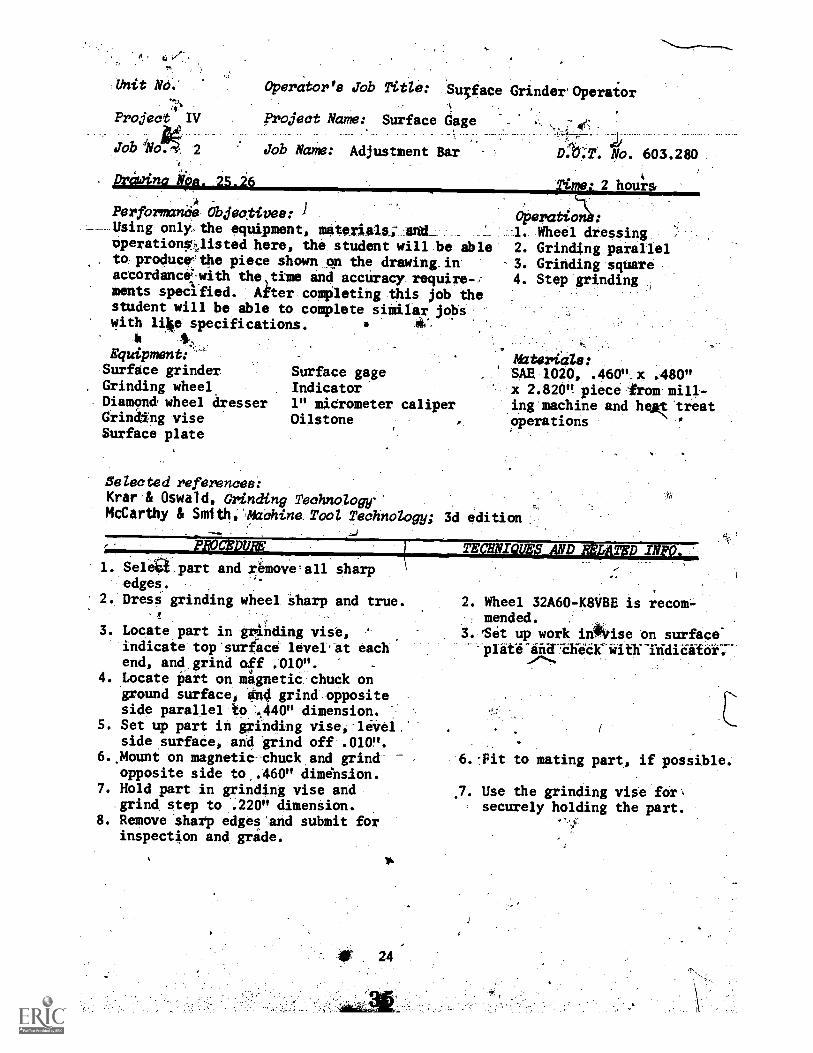
Unit NO."-,4
Project IV
Job dNA 2
prawina klep. 25.26
Perfbrmanas Objeo,tives: 1Using only the equipment, aB.e,i.ait;ji1d
operations%listed here, the student will be ableto producethe piece shown on the drawing inaccordance.with the,time and accuracy require-ments specified. After completing this job thestudent will be ible to complete similar jobswith like specifications.
Equipment:Surface grinderGrinding wheelDiamond, wheel aresserGrinding viseSurface plate
Operator's job Title: Su5face GrinderOperaior
project Name: Surface Gage --
Job Name: Adjustment Bar
Surface gageIndicator1" micrometer caliperOilstone
D.r;T'. No. 603.280
;limo: 2 houl*s
Operati;11:1. Wheel dressing2. Grinding parallel
-3. Grinding square4. Step grinding
hdtsrials:SAE 1020, .460" x .480"x 2.820" piecelems mill-ing machine and heat treatoperations
Selected references:Krar & Oswald, Grinding Technology'McCarthy & Smith,'Machina Tool Technology; 3d edition
;0 *.
1. Selett part and rêmove'all sharpedges.
2. Dress grinding wheel sharp and true.!
3. Locate part in grOding vise,indicate top surface level-at eachend, and grind off .caoft.
4. Locate liart on mignetic chuck onground surface, and grind oppositeside parallel to ',440" dimension.
5. Set up part in grinding vise, levelside surface, and grind off .010".
6..Mount on magnetic-chuck and grindopposite side to .460" diminsion.
7. Hold part in grinding vise andgrind step to .220" dimension.
8. Remove sharp edges'and submit forinspection and gride.
TEct la c IN
2. Wheel 32A60-K8VBE is recom-mended.
3. Set up work irighrise on surface--plate
6.-Fit to mating part, if possible.
7. Use the grinding vise for,securely holding the part.
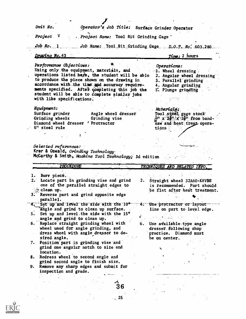
alit No.
Project V
Job No 1
&Wing No.43
#
Operator's glob Title: Surface Grinder Operator
. Project Name: Tool Bit Grinding Gage"
Job Name: Tool.Bit Grinding Gage D.O.T. No: 603.280
Time: 2 hours
Performance Objectivee:Using only the equipment, materials, andoperations listed heie, the student will be ableto produce the piece shown' on the drawing inaccordance with_the time-Atd accuracy require-ments specified. After sOmpleting this job thestudent will be able to complete similar jobswith like specifications.
Equipment:
Surface grinder Angle wheel dresserGrinding wheels Grinding viseDiamond wheel dresser ''Protractor6" steel rule
Operations:-I. iiheel dressing ,2. Angular'iwheel:dressing-.3. Parallel grinding4. Angular grinding5: Plunge grinding
Materials:Tool speil, gage stock
x`2V. dk"24P from band-saw andleat tre opera-tions
Selecteatmferences:Krar & Oswald, Grinding TechnologyMcCarthy & Smith, Machine Tool TeohnoZogy; 3d edition
PROCEDURE'
1. Burr piece.2. Locate part in grinding vise and grind
one of the.parallel straight edges to..;,,clean up.
3: Reverse part and grind opposite edgeparallel.
-1-We1 -the-tide-With- the '10°-
an- gle and grind to clean up surface.5. Set up and level.the side with the 15°
angle and grind to clean up,6. Replace straight grinding wheel with
wheel used for angle grinding, anddress wheel with angle dresser to de-sired.angle.
7. Positionrpart in grinding vise andgrind one angular notch to size andlocation.
8. Redress wheel to second angle andgrind second angle to finish size.
9. Remove any sharp edges and submit forinspection and grade.
A36
25
TECHNIQUES ANDINLATED INFO.
Straight wheel 32A60-K8VBEis recommended. Part shouldbe flat after heit treatment.
---'4.--1Usei3rotractor -or-layout-
line on part to level edge.
,
6. Use aVailable-type angledresser.following shoppractice. Diamond mustbe on center.
atit. No.
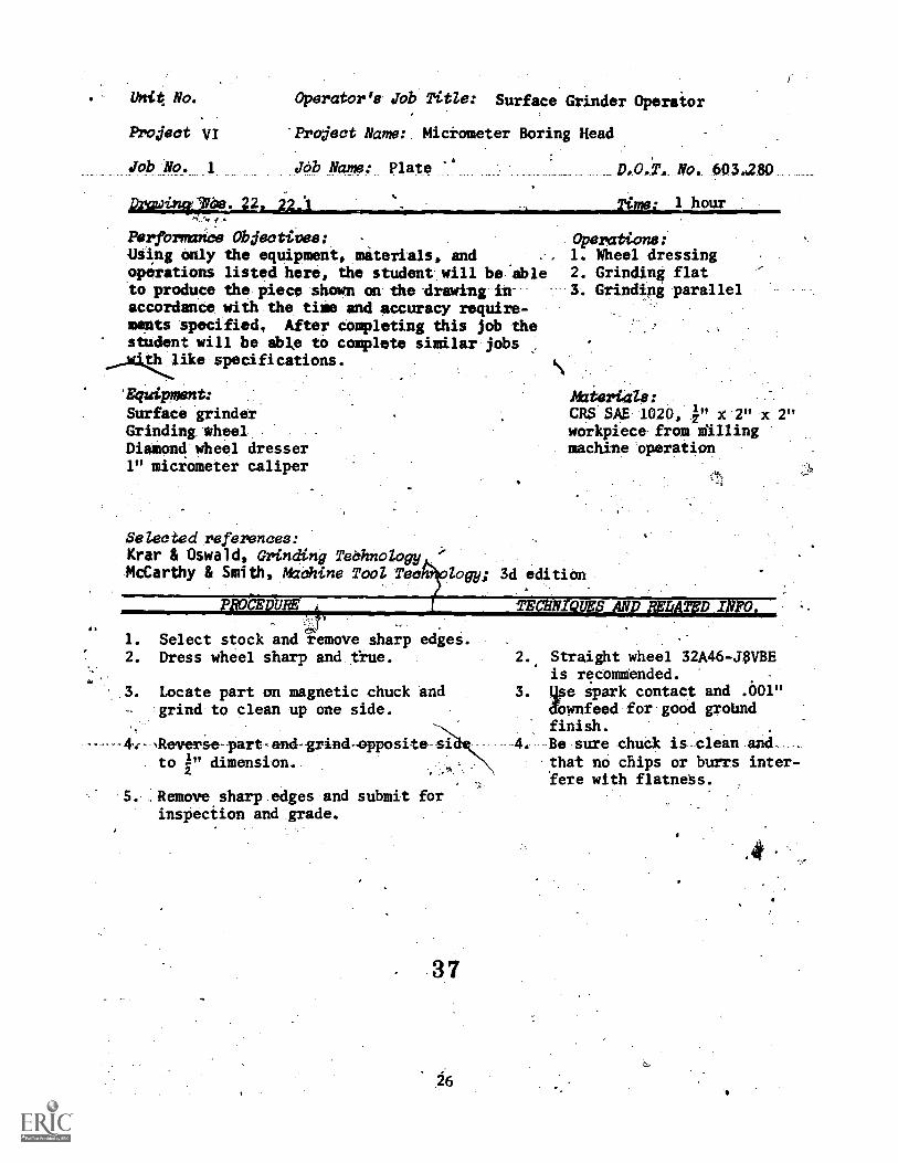
Project VI
job NO.
Operator's Job Title: Surface Grinder Operator
'Project Name: Micrometer Boring Head
Job Name: Plate ''
ftrfbrmance Objectives:Msing only the equipment, materials, andoperations listed here, the student will be ableto produce the piece shown on the drawing in-accordance with the time and accuracy require-ments specified, After completing this job thestudent will be able to complete similar jobs'th like specifications.
'Equipment:
Surface grinderGrinding wheelDiamond wheel dresser1" miciometer caliper
Selected references:Krar & Oswald, Grinding TeOhnologyMcCarthy & Smith, Machine Tool Tee
NO. 6034280
Operations:1. Wheel dressing2. Grinding flat3. Grinding parallel
M1ie2'1418 :CRS SAE 1020, i" x 2" x 2"workpiece from stillingmachine operation
bogy; 3d edition
uocEpum_
1. Select stock and remove sharp edges.2. Dress wheel sharp and &ue.
3. Locate part on magnetic chuck andgrind to clean up one side.
,Reverse-part-and-grind-opposite-sito i" dimension.
S. _.Remove.sharp edges and submit forinspection and grade.
37
TECANIQUES ANDffIATED INFO.
2. Straight wheel 32A46-J$VBEis recommended.
3. qse spark contact and .601"dOwnfeed for good groUndfinish. . .
. Be sure chuck is clean andthat no chips or burrs inter-fere with flatness.
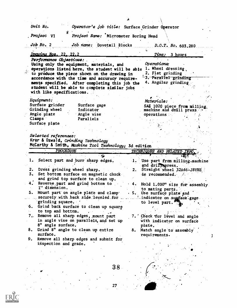
Unit No.
Project VI
Job No. 2
A
Operator's jab title: Surface,Grinder Operator
Project Name: 'Micrometer Boring Head
job name: Dovetail Blocks
Drawinc Noe. .22*A.2
Perfarmance Objectives: .
Using only the equipment, materials, andoperations listed here, the student will be ableto produce the piece shown on the drawing inaccordancewith the time and accuracy require-ments specified. After completing this job thestudent will be able to complete similar jobswith like specifications.
Equipment:Surface grinder Surface gageGrinding wheel IndicatorAngle plate Angle viseClamps ParallelsSurface plate
Time: 3 hours
Operations:1. Wheel dressing,2. Flat grinding
' 3. -Parallelgrinding4. Angular grinding.
Materials:
SAE 1020 piece from milling,machine and drill press -
operations /4
Selected references:Krar & Oswald, Grinding Technology
McCarthy &.Smith, Machine Tool Technology; 3d edition
PROCEDURE
1. Select part and ,burr sharp edges.
2. Dress grinding wheel sharp.3. Set bottom surface on magnetic chuck
and grind top surface to clean up.Reverse.part and grind bottom to1" diiension.
5. Mount part on angle plate and clamp'securely with.back side:leveled_forgrinding square.
6. Grind back surface to clean up squareto top and bottom.
7_ Remove all sharp edges,.mount partin angle vise on parallels,and set up8° angle surface.
8. Grind 8° angle to cleanup entiresurface.
9. Remove all sharp edges andinspection and grade.
submit for
3 8
27
TECHNIQUES AND MUTATION-.
I.
2.
Use part from milling.machineand drirtwress.Straighewhel 32A46-J8VBEis recommended.
4. Hold 1.000" size for assemblyto mating parts.
S. Use surface plate andindicator on s ace-gageto level part.
V.
7.' Check 'for level and anglewith indicator on surfaceplate.
8. Match angle'to assemblyrequirements.
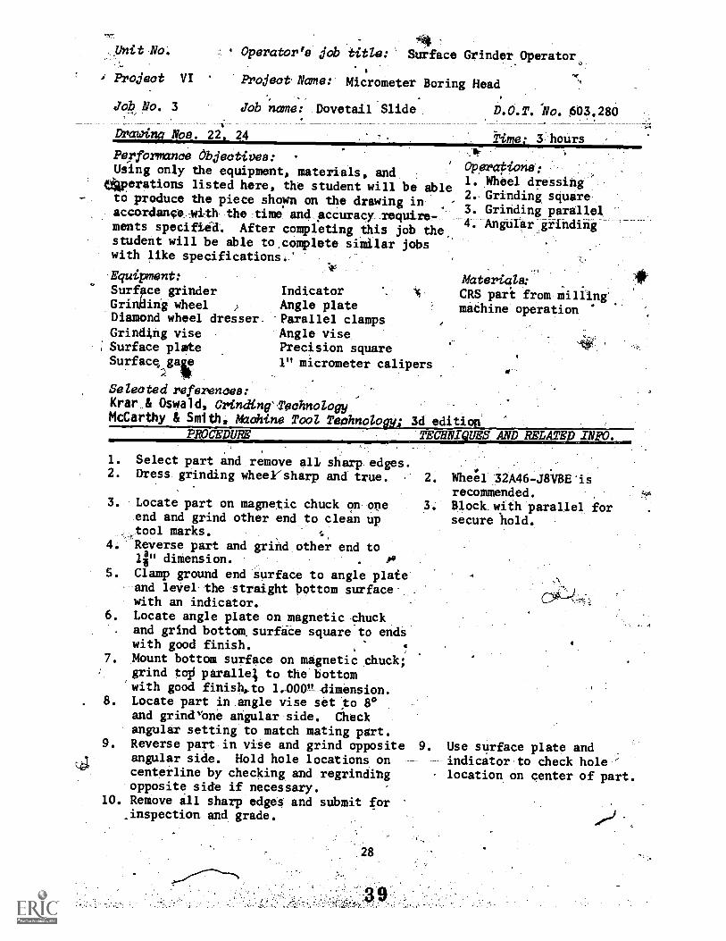
unit No.44
Operator s job title: Surface Grinder Operatoi%. 8
, Project VI Project Name: Micrometer Boring Head
job No. 3 Job name: Dovetail Slide
DrawilR Noe. 22. 24
Performance Objectives:Using only the equipment, materials, and
ikAperations listed here, the student will be ablto produce the piece shown on the drawing inaccordance with the time and accuracy require-ments specified. After completing this job thestudent will be able to.complete similar jobswith like specifications.'
'40
Equipment:
D.O.T. No. 603.280
Time: 3 hours
Surface grinderGrinding wheelDiamond wheel dresser.
Grindtng viseSurface plateSurfacyair
IndicatorAngle plateParallel clampsAngle visePrecision square
1" micrometer calipers
OPeraPi°":1. Wheel dressing2. Grinding square3. Grinding parallel4. Angular gfindifig
Materials:CRS part from millingmachine operation
Selected references:Krar & Oswald, Grinding'TschnologyMcCarthy & Smith, M2chine Tool Teohnologyi 3d edition
PROCE TECliNI VHS AND RELATED INFO.
1. Select part and remove all sharp edges.2. Dress grinding wheersharp and true. 2.
3. Locate part on magnetic chuck on oneend and grind other end to clean uptool marks.
4. Reverse part and grind other end toli" dimension. po
5. Clamp ground end surface to angle plaieand level the straight bottom surfacewith an indicator.
6. Locate angle plate on magnetic-chuckand grind bottowsurfice square to endswith good finish. 4
7. Mount bottom surface on magnetic chuck;grind toil piralle; to the bottomwith good finish,to 1.-000g-dimension.
8. Locate part in angle vise set to 8°and grindvone angular side. Checkangular setting to match mating part.
9. Reverse part in vise and grind oppositeangular side. Hold hole locations oncenterline by checking and regrindingopposite side if necessary.
10. Remove ill sharp edges and submit for.inspection and grade.
28
Wheel 32A46-J6BE isrecommended.Block with parallel forsecure hold.
9. Use surface plate andindicator to check hole 'location on center of part.
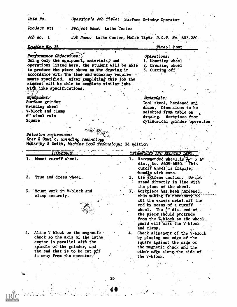
Unit No.
Project VII
job No. I
proltbict Alok3S
Operator's Job Title: Surface Grinder Operator
Project Name: Lathe tenter
Job Name: Lathe Center, Morse Taper D.O.T. No. 603.280_ _
4Tipmrpl hour
Performance Object-wee:Using only the equipmen , materialsandoperations listed here,the student will be able'to produce the piece shown op the drawing inacCordance with the time and aCcuracy-require-ments specified. After complitinithis job thesti4ent will be able to complete similar jobs
like specifications.
84Uipment:'Surface grinderGrinding wheelV-block and clamp6" steel ruleSquare
_
Selected references:Kreir & Oswald, Grinding Technology
-McCarthy & Smith, Machine Tool Technology; 3d edition
Operations:1. Mounting wheel2. Dressing wheel3. Cutting:off
Attterials:
Tool steel, hardened anddrawn, Dimensions to beselebted from table ondrawing. Workpiece fromcylindrical grinders-operation
. Mount cutoff wheel.
2. True and dress wheel%
3. Mount work in,V-block andclamp securely.
4. Aline V-block on the magneticchuck so.the axis of the lathecenter is parallel with thespindle of the grinder, andthe end that is to be cut)Diffis away from the operator.
29
. Recommended wheeljis ?T" x 6"dia., No., A60M-6R50. Thiscutoff wheel.is fragile;handp with care.
2. Use eXtreme caution. Do,noti. stand4irectly in line with
the plane of the wheel.3. Workpiece has,been hardened, ,
thus making ifnecessarrcut the excess metal off theend by means of a cutoffwheel. Ihe l-P1 dia. enclof
the piec should protrudefrom the block so the wheel,guard will mass the V-blockand clamp. .-
4. Check alinement of the V-blockby placing one edge of thesquare against the side ofthe magnetic chuck arid theother ecte along,the side ofthe V-block.
PROCEDURE TECWNIQUES AND REPUTED INFO.
5. Position cutoff wheel in relation- 5. Place the cutoff wheel overihip to the end of the.workpiece. the workpiece and measure 41P
. -i from the end of the work to00
. the side of the cutoff wheel.6. CUt off by*using longitudinal. 6. DO NOT USE TRANSVERSE TAW
table travel. TRAVEL.
7. After end has been cut off, sub- .
mit for inspection and grade.
41
30
Feed wheel slowly intb work-piece.CAUTION:Do not stand directly in linewith the cutoff wheel. Usecoolant to avoid overheating.
-tar
&Wit No.
Frojeot VII/
j'a AO. 1
prohfriatiaa- 36, 39i:
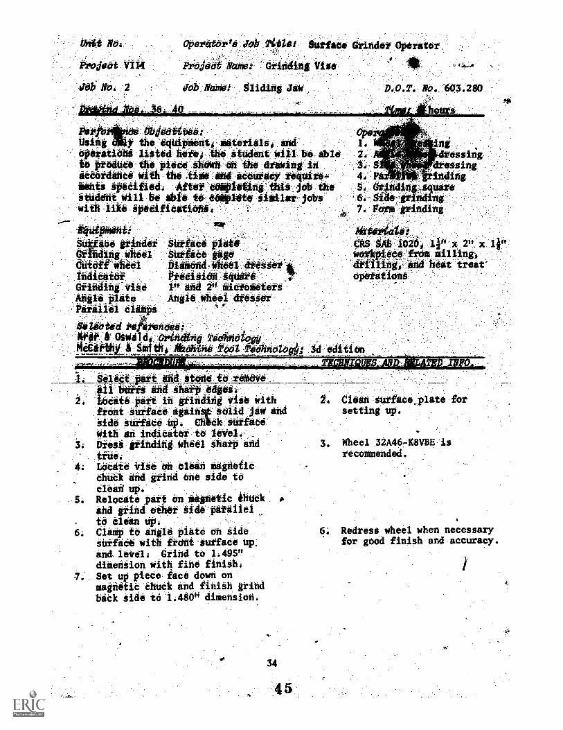
ParfbrmanOe'dpitootioec.Using only the equipment,.WiterialiGoperation's , listed 'here, the St*Ielit Will "be ibleto:produce the piece iihoinsi.oittlie drawintikaccordefte ,with :the tile :Ind eteeikko tignite-=Bents specified:. Aftiwitettleting 'thinAtib the.itudent Win be able to toplete. slat at. jObt-with like spicificitions
OPefttbrte JOb Teti*: Suits*, ar1.ftitetiVerilt0
Projeet Now Grinding %rite'
Job Mom: Bite
4quipment:-&whine grinder ,Grinding'wheels4Angle plateGrinding visePrecision squareMagnetic V-blockDepth micrometer
60t,206
Clot& .
Sb tidijoulAtikt.;
Parallel tiaipiurtadi plate
jndicator.1" and V, aiCrOiattersVernier eallporsMagnetic parallelsDiamond Wheel dresser
Selma te d references:Krar& Oswald, Grinding reohnotoggMcCarthy & Smith, Marine tot reohnotogy
Aktoota4,1evAg. ViPxWokPilite Etta miiidr/nit*, eta heatoptitidm
Ali editionWiTsy:4-0:11;;41111111.111111111111111=1111111111MINGATriPT:3-61,7
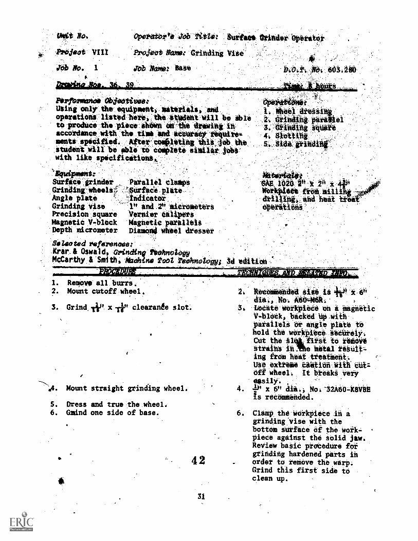
. Remove all burrs.2. Mount cutoff wheel.
3. Grind 4° x clearante slot.
A4. Mount straight grinding wheel.
S. Dress and true the wheel.6. Gsdnd one side of base.
4 2
31
6°,
3, -lietatt'Werkplete eh i MagneticV-Oldek,-bieked **ith :pakaileU or eagle plata tb'hold the:WOrktdece:SeCiirelY,Cut the §14firat,tO tedidiastrilas-ialhe otai rebUit=ing fie* hettlreitieht:USe extreatetiff wheel:, It Dreak. Veryeailly,
4. 40 X 6° d*. Mo:-32A60=k8Vatis reoemtended.
6. ClaMp. the woiltpieCe Iii a
grinding:Vise with thebottom surface. Of the-Work=piece against the Stolid jaw.Review baSid prirtedUre forgrinding hardened parts inorder to_tenkive theyarp;Grind this firat aide toclean up.
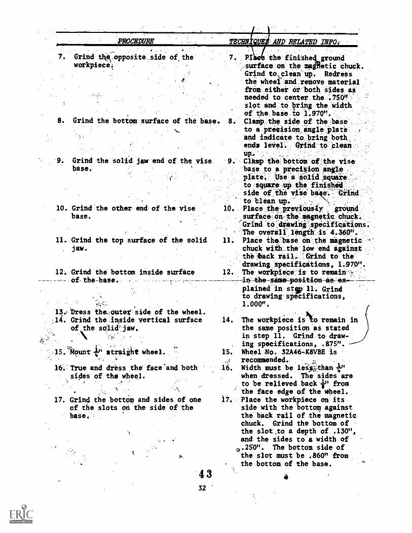
. .Grind the:opposite side of_theworkpiece.
8. Grind the bottom surface of the base.
9. Grind the solid jaw end of the visebase.
10. Grind the other end of the visebase.
11. Grind the top surface of the solidjaw.
12. Grind the bottom inside surface-of- the-base. - - -
Dress the, outer side of the wheel.14. Grind the inside vertical surface
of the solid jaw.
15. Itount 4." straight wheel.
16. True and dress the face 'and bothsides of the wheel.
,
:
17. Grind the bottom and sides of oneof the slots on the side of thebase.
4 332
7. Pr the finishet groundsurface on the maglietic chuck.Grind tocleari up. Redressthe wheel and remove materialfrom either or bath sides asneeded to center the '.750"slot and to Iwing the widthof the base to 1.970".Clamp the side of the baseto a precision, angle plateand indicate to bring bothends level. Grind to clean
. Clamp the bottom of the visebase to a precision angleplate. Use a Solid squareto square up the fiiiShedside of the vial,' bake. Orindto blean up. N
1 . Place the PrevieuelY Pound_surface on #o- magnetic chuck.'Grind to:drawing-specifications.The overall length is 4.360".
11. Place the:base on the magneticchuck with the low end againstthe back rail. 'Grind to thedrawing specifications, 1.970".
12. The workpiece is to remainVie-same-position as-ex
plained in stop 11. Grindto drawing specifications,1.000".
14. The workpiece isNo remain inthe same position as statedin step 11. Grind to draw-ing specifications, .875".
15. Wheel No. 32A46-K8VBE isrecommended. -
16. Width must be leiskthan +"when dressed. The sides areto be relieved back ip fromthe face edge of the wheel.
i . Place the workpiece on itsside with the bottom againstthe back rail of the magneticchuck. Grind the bottom ofthe slot ,to a depth of .130",and the sides to a width of.250". The bottom side ofthe slot must be .860" fromthe bottom of the base.
-PROCEDURE -TECHNIQUES AND RELATED INFO.
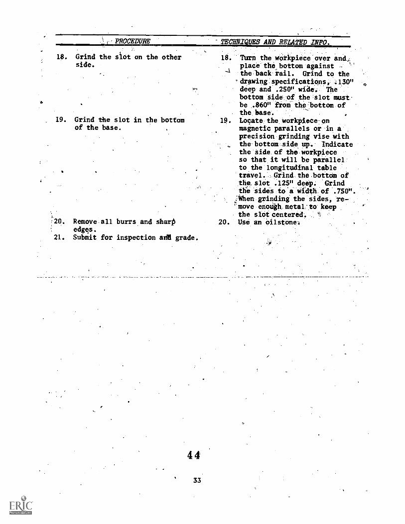
18. Grind the siot on the otherside.
19. Grind the slot in the bottomof the base.
s
20. Remove all burrs and shartiedges.
21. Submit for inspection &AR grade.
18. Tura the workpiece over and,place the bottom against -
the back rail. Grind to thedrawing specifications, .130"deep and .250" wide. Thebottom side of the slot must-be .860" from the bottom ofthe base.
19. Locate the workpiece onmagnetic parallels or in aprecision grinding vise withthe bottam side up. Indicatethe side of the workpieceso that it will be parallelto the longitudinal tabletravel. Grind the bottom ofthe slot .125" deep. Grindthe sides to a width of .750".;When grinding the sides, re-.
move enoligh metal to keepthe slot centered.
20. Use an oilstone:
t No:
Projedi Vit.!
Ob. No. 2
Pioddet &mei
Jaw
.;040.10idipo06..1
P8teb141004-,Obil6oitwe:UsiSi 81114y the 'equioliefitis
efieritidhe hated heie1 the atUdent will be ableo otodute the piddei hitath-dh the dfiaiihg,ih
AC6)446666 4it1 t the :tithe . Md itotifady.trequite'mints soaked; Atterst_qopiotisc this_JOb :thestudent *Ail he side te, "pie*with like speditiestiohis
1400,060hii . .
$-.; aoe afrindek §tatied pJa41 ng wheel
. tutfide 0.0&Ede. stio biamonci,*weel dtOsser
afifidihif -the 20, JaAN06,iteet
AtiiileffiAte Angle wheel tifes.$0t
Parallel diatiPS r
HO WWI Mfeittieed..-.101t4C4Weldi,:tiii#14161tPAN6441/-
itettOthi. Sift* /,41,01,redibioz44
2;:3E S.
4, PS. gritidi0S
toe-gat:Erin&7. P0111 t0/40ding
0A.
egs sAg 1626# lin x 2"'x 1W0ftpie4e4f6m'dfilliigo -aid heat treat'
°Pelit1011V
1. 4#0,0-.06iCahd:atene.i6'4610Ve..._edgeii
iheite Oaft in gfisding vise ifithkiest ahrfaCer ageihat adlid :OW _andkide surface up. Chtekfaiifface:
With eh indititer.tdbieei:grinding:Wheel Agit andtxtieLOCAte vise dkelein MagnefieChUCk and gfind one aide tdCleah hp.RelOCate part en sigfietit owl( 0
ihd grind 6thef alde-Pit41101
t.0 dean6: Clinip tO tsgie piste dh iide
afiff404 with f*chit-auffate up:
and leirel; diihd tto 1.495"diiefiiidh With fine fihiSh;
7. Set,up piece face dOwn on.Maghetie ditlek And fihiah grindbeak side id 1.4800 dimension.
34
OW surface.plate forsetting up.
Wheel 32A4648VBE isrecommehded.
6; Redress wheel when necessaryfor good finish and accuracy.
1
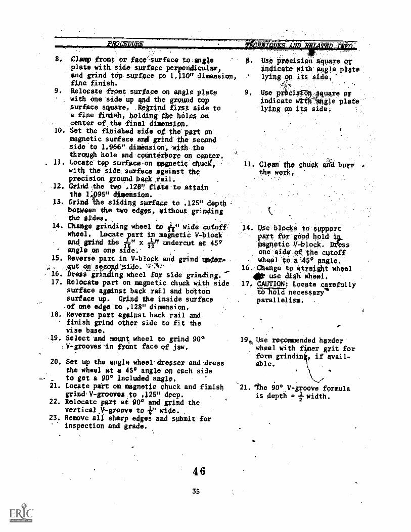
8. Clamp front or face surface to angleplate with side surface perpendicular,and grind top surface,to 1,110" dimension,fine finish.
9. Relocate front surface on angle platewith one side up and the pound topsurface square, RekrinA first side toa fine finish, holding the Wiles oncenter of.the final dimension.
10. Set the finished side of the part onmagnetic surface and grind the secondside te 1,960" dimension, with thethrough hole and counterbore on center,
. 11. Locate top surface on Magnetic chuolt,with the side surface against theprecision ground back rail.
12. Grind the two .128" flats to attainthe 1495u dimension.
13. Grind the sliding surface to .125" depthbetween the two edges, without grindingthe sides.
14. Change grinding wheel te Tin wide cutofwheel. Locate part in magnetic V-blockand grind tbe x h" undercut nt 459angle on one side. ,
15. Reverse part in V-block and grind under,
15ut16. Dress grinding wheel for side grinding.17. Relocate part on magnetic chuck with side
surface against back rail and bottomsurface up. Grind the inside surfaceof one edgei to .128" dimension.
18. Reverse part against back rail andfinish grind other side to fit thevise base.
19. Select and mount wheel to grind 90°V-grooves'in frOnt face of jaw,
20. Set up the.angle wheel-dresser and-dressthe wheel at a 459 angle on each sideto get a 900 included angle,
21. Locate part on magnetic chuck and finishgrind V-grooves to .125" deep.
22. Relocate part at 90° and grind thevertical V-groove to in wide.
23. Remove ail sharp edges and submit forinspection and grade.
4 6
35
8. Use preci.aiga 4qUare or
indicate With appe elatelying en its Side,'
9' Use p;4ig."-T--"'Pfluare erindicate Witk-angle platelying on it§ side.
11, Clean the chuck alid burrthe WO*,
14. Use blocke to Supportpart for geed hold
magnetic ,V-block. Woesone side of the cutoffwheel to. A 45° angle.
16, Change to straight wheel
4/0X use dieh wheel.1/. CAUTION: Locate carefully
roThiMinecessari"parallelism.
I.
Use recommended harderwheel with f. er grit forform grindin if avail,able.
. 'the 90° V-groove formulais depth = width.
Unit No.
Project IX .)
Job No.',
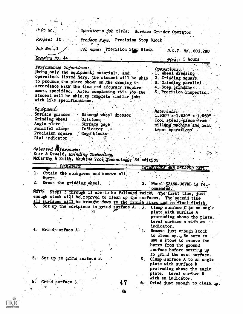
Droding Nol 44
Operictor'p 01) title: Surface Grinder Operator
Project Name: Precision Step Blockt4
Job name: ?recision Sim, Block
Performance Objectives:1,Using only the equipment; materials, andoperaiions listed here the student will be ableto groduce the piece shc+Wn on,the drawing inaccordance with the time and aCcuracy require-ments specified. After 'Completing this job thestudent will be, able to complete similar lobswith like specifications.
Equipment:
Surface grinder.Grinding wheelAngle plateParallel clampsPrecision squareDial indicator
D.O.T. No, 603.280
Time: 5 hours
-
Operations._:,1. Wheel dressing .-
2. Grinding square3. Grindinis paralIel4. .Step. grinding
.5. PreciSion inspection
4 Diann's' wheel dresserOilitoneSurfape gage"'
InaicatorGage blocks
Materials:1.530" x 1.530" x 1.550"
Tool.steels piece fiommillg machine and heattreat opeiatione
Selected Aferences:KOar & Oswald, 0,1.441ng Technology, ..
.McCarthy. & ,Skaf04. Aflehine'To4;reohacitoey; 3d edition
4.-70-Tkoleigi.WINNIRRINIIIIIININNIIIIIIIIMAILWaftliSIVIT010.20,3*-101,4' "01. Obtain the wor)cpiece,and remove
burrs.2. Dress the grinding ,wheel 2 . Wheel 32A60 J8VBE is rec-
ommendga.140TE: Steps 3 through 11 are,to be followed twic'e. The first time, justenough stock wiAl be,removed to clean up the surfaces. The seCond timeall surfaces will be brOught-dewn to the finiih sizes and to final finish,3. Set up the workpiece to grind surface A. 3. Clamp surface C to an angle
plate with surface Aprotruding above the plate.Level surface A with anindicator.
4. Grindsurface . Remove just enough 'stockto cleari up. ,, Be sure to
use a stone to remove theburrs from the groundsurface before setting up;to grind the next surface.
5. Clamp surface A to an angleplate with surface Bprotruding above the angleplate. Level surface B.with an indicator.
47 6.. Grind just enough to clean up.
5.. Set up to grind surface B.
Griad surface B.
J6
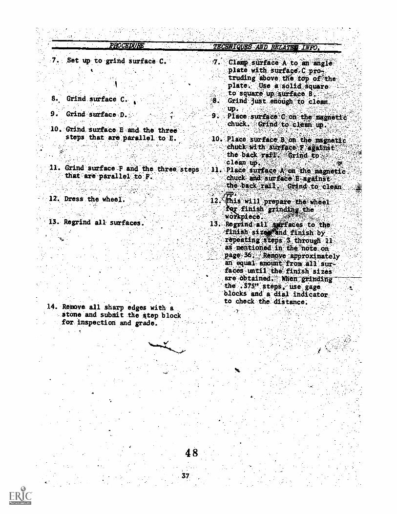
10. Grind, surface.E and the threesteps that are parallel to E.
Clamp tiCa A to'en-angte':plate with surfa98...0truding above the tOP Oetheplate. Use a Selid Squareto square Up;sUifica.B.
. Grind just,ehOugh tO clean.up. :9. . Place surface 'pt On the niairott-
.11. Grind -.surf ace -F and_the three stepsthat, are'parallel :toy:
plaCe, surfaCechuck?the baCk rIcleanup.
11; PlaCe ace-,
1 . Dress the wheel.
14. Remove all sharp edges with astone and submit the step blockfor inspection and grade.
is: will prepare the: .wheel-'finith grin e
.wor piece.:13.: Regrind.all,:: aCeS..-to'the
fiaiSh byrajieitintAteps':1::throxigh 11,
-me40#04-.1*:ihe *lie- On.Approximately
an ,.erqual ameOtkfrem all:.sur-faCeSfrUntil-:0,e.,.finish sizesare obtained.:10/404,pitidinl-7the .375" stepa.,:. Use:, gageblocks and a dial indicatorto check the._dlitance:
Unit No.
hvject X
Jcb No, 1
Drawili No. 45
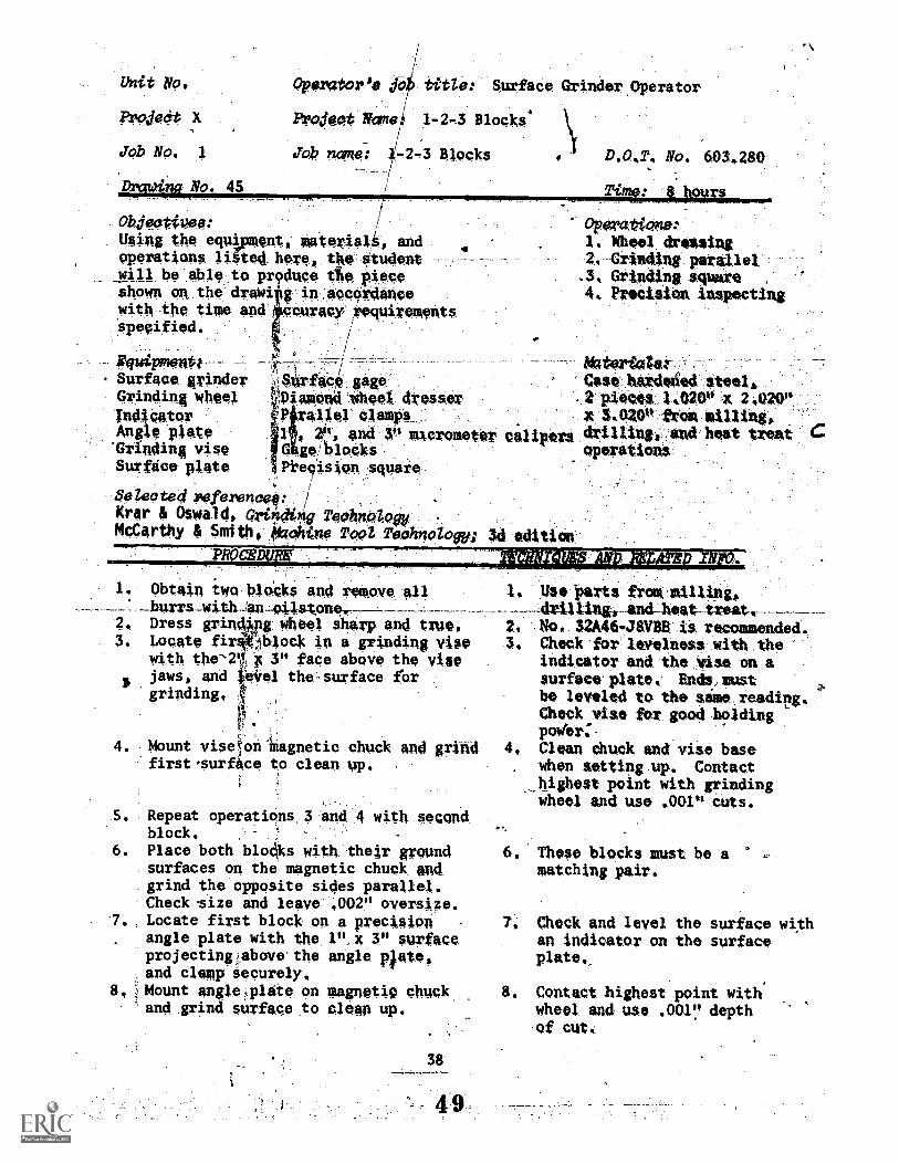
PPOratorPS. jo)fr tf.t4e: SurfaCe Grinder.Operator
EV4460 Niame 1-24 Blocks'
JOb norRe.7 1/.-2-3 Blocks
obieativea:Wag the equi ", @nit, MaterialS, and
operations li ted here. rhe #tudeawill be able to produce tfie piecesheWn aR the drawi'g in accordancewith the time and ccuracy requirementsspecified.
Rquipmentit--Surface grinderGrinding Wheel
IndicatorAntile plateGi Inding vise
Surface plate
ftrfac gagepiamondWheel dresser7P ral/er clamps
. 4", and 3" micrometerg'1:11ocks
Pivcision square
Selected Peferencel:Krar & Oswald, grinding Technology
.
McCarthy & Smith, *chine Tool TeohnologY;
D.OAT. No. 6034280
Time: inm4N1
Operations:1. Wheel dressing2.---Grinding parallel.3, Grinding square ,
4. Preciiion inspecting
calipers
:
*tartan;Case hardeied steels,.2 :pieces 1420" X 2.020"x LOW from milling,drilling, and heat trate Coperations
1. Obtain two blacks and remove 011
2. Dress grinclOing wheel sharl, end tr40,3. Locate firW;Iblock in a grinding vise
with the-2$1c 3" face above the viseJaws, and Oirel the,surface fbrgrinding,
4. Mount viseton Magnetic chuck and grihdfirst,surfSce to clean up.
ad edition
. Repeat operations,3 and 4 with secondblock.
6. Place both blod.ks With their groundsurfaces on the magnetic chuck andgrind the opposite sides parallel.Check size and leave .002" oversize.
7. Locate first block on a precision 7,
angle plate with the 1"]( 3" surfaceprojectingabove.the angle plate,and clemp securely.
8, Mount angleiplate on magnetiC chuck 8.
'and grind surface to clean up.
Use Parts frowmillingo,drillingt and-heat treat.
2. No, 32A46-4.76VBE is recommended,3. Check for levelness with the
indicator and the vise on a
surface plate. Ends:mustbe leveled to the sime reading.Check vise for good hcadingpoWer:-
4, Clean chuck and vise basewhen setting up. Contacthighest point with grindingwheel and use .001" cuts.
6, These blocks must be amatching pair.
41,
Check and level the surface withan indicator on the surfaceplate,_
Contact highest point withwheel and use .001!, depth.of cut.
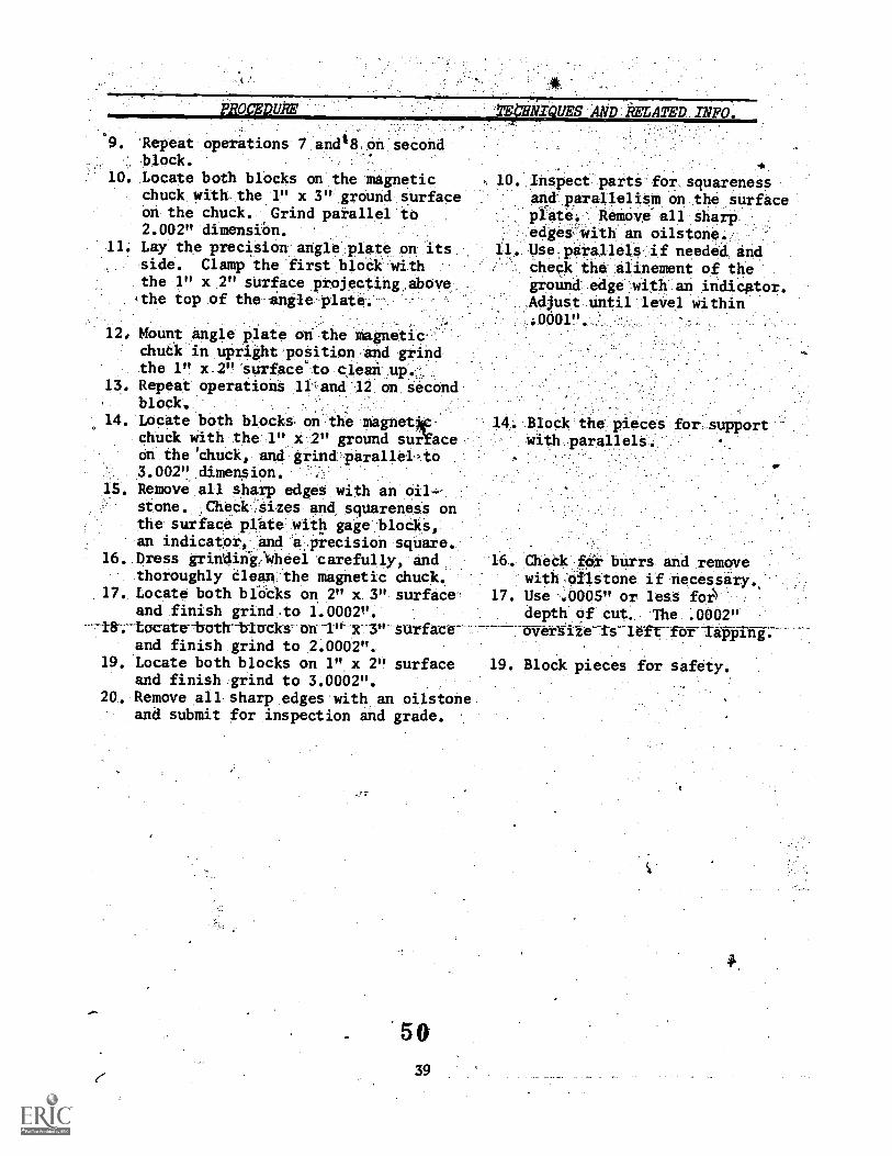
PROCEDIVE 1We1lill'QUES AND:AIATED_INFO-,
. 'Repeat operations 7 and48 on second
block.10. Locate both blocks on the magnetic
chuck with. the 1" x 3" ground surfaceon the chuck. Grind parallel to2.002" dimensiOn.
11. Lay the precision angle plate on itsside. Clamp the first bloCk withthe 1" x 2" surface projectinuabovethe top of the angle plate.
h 10. Inspect parts for squarenessand parallelism on the surfaceplate.' Remove' all sharpedgei with an oilstone.
1 . Use parallels if needed andcheck the alinement of theground-edge with an indicator.Adjust until level within:ODOM
12e Mount angle plate ori the magneticchuck in upright position and grindthe 1" x-2" surface to clean up.
13. Repeat operations ll'and 12 on second. block.14. Locate both blocks on the magnet*.
chuck with the 1" x 2" ground surYaceon the chuck, and grind parallel-to3.002". dimension. .
15. Remove all sharp edges with an oil--stone. Check .sizes and squareness onthe surface plhte with gage blocks,an indicator, and aprecision square,
16. Dress grindini:Wheel carefully, andthoroughly Clean the magnetic chuck.
17. Locate both blOcks on. 2" x 3" surfaceand finish grind.to 1.0002".
and finish grind to 2.0002".19. Locate both blocks on 1" x 2" surface
and finish grind to 3.0002".20. Remove all sharp edges with an oilstone
and submit for inspection and grade.
14; Blco'ck iheA:dees forsupportwith parallels.'
5039
CheCk..fOr bUrrS and removewith,eilstOne if.:necessark..
17. Use -.0005" or leas folk. depth of cUt. The .002"
. overstre, is rofx "few lapping.
19. Rlockpieces for safety.
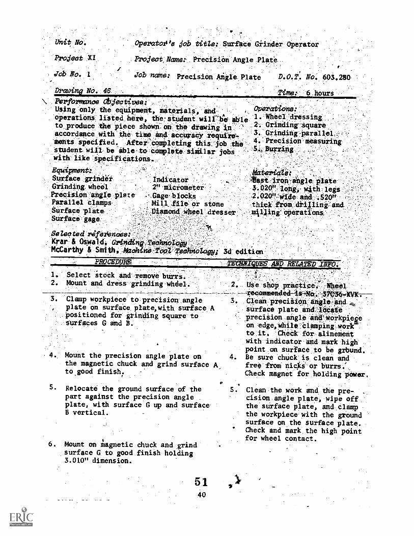
Unit No.
Project )0:
Job No. 1
Drawi No. 46
Operatoe job titZe: Surfhce Giinder Operator
Project, Name: Precision Angle Plate
Job name: Precision Angle Plate D.O.T. No. 603.280
Ti : 6 hours
\ fteormance Objeetivea:Using only the equipment, mateiials, and-operations listed here, the. student wiWgeto produce the piece shown.. on ihe drawing in'accordance with the time and accuracy require'Merits Specified. After 'cOmpleting this jobstudent will be able- to complete siiilar jobswith iiice specifications.
OPerations:dine 1. Wheel 'dressing
, 2. Grinding-square
3.. Grinding -Parallel-4. Precision measuring
1.11.1Tring
Equipment:Surface grindirGrinding, wheil
Precision angle plateParallel clampsSurface plateSurface gage
l&ztei'iclo:apt tiofi iigle plate
3.020". long,, w4th legs ,..-
2.020", wide and .520"thick from driAlink andmis4ing *operations
Selected rdfeziencee:Krar & Oswald, Grinding TeehnoMcCarthy & Smiths Maehine'PoPi TeehnologY; 3d edition
PROCEDURE
Select stock and remove burrs.. Mount and dress grinding whdel.
TECSATIQUES AND RELA2'ED INFO.
GS e shoP Preeciee.--recommended-is4Ne4-'3.V364VK;-
.
.Clean precision, angle4pd
. .
surface plate and:10CatepreciSion angle 114' Woikpiegeon edge, while .Clamping workto it Chick fOr alinementwith indicator and mark highpoint on surface to be grbund.Be sure chuck is clean andfree from nicks or burrs.'Check magnet for holding power.
Clean the work and the pre-cision angle plate, wipe offthe surface plate, and clampthe workpiece with the groundsurface on the surface plate.Check and mark the high pointfor wheel contact.
3. Clamp workpiece to precision angleplate on surface plate,with surface Apositioned for grinding square tosurfaces G and B.
4. Mount the precision angle plate onthe magnetic chuck and grind surfaceto.good finish.
Relocate the ground surface of thepart against the precision angleplate, with surface G up and surfaceB vertical.
5.
6. Mount on magnetic chuck and grindsurface G to good finish holding3.010" dimension.
5 1
40
5.
P/OCEDUE
Relocate-the-part .on _the preasionangla'plate td' grind surface itsquare to end and face A..
. Grind 'face 'Remove .pgroOld-,
10
O t
,;;;AA.ood'surfice fin4h.
r. Locate,'ace G on Magiietic Cluck
surface 13 paraf10. clownsion.
edget and set_ up part on faceri surface D to '2.00114
'dimensioBUfir sha edges and set up parton f Grind'itirface C to2.00Q" d
12. Locate workpiece against tiack raiof magnetic ..c,bu4 -and .contact theinner surfaae F. Grind this surfaceto .5001.! dimension.
13. Relocate part -to -grind surface E to,500" dimensiOn.
14. -Remove all sharp edges and submitfor inspection and--grade.
41
TE7NIFES AND: liNLAYND INFO:;
Set up-iiith precision angle. , . .
plate on edge, grOund faceagainat angle :plate, andgroUnd edge .Un. Surfate plate.
BlOCk 'part On, the,.Magneticchtick, , .
power:, Takeahd:check`I'streqUiro. :a
1 '.1.BefsUrei'!ttif,wilisl!: laagnaticchuck. clean'.befOre'4ettin*
wor
. -.Back rail uw e
careful-net X0 ruprinto thi'vertical siirface idth 611grindint'wheei or guard,
3. Always 'observe grinding fromthe right-hand tide of themachine to aVoid fl ngparticles .
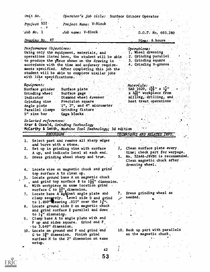
Unit No.
l'oject XII#
'Job No. 1
Drawing No. 47
Operator's job titZe:
Project Name: V-Block
'Job name: V-Block
Surface' Grinder Operator
Performance Objectives:Using only the equipment, materials, andoperatibns listed here, the student will be ableto produce the Plece shown on the drawing inaccordance with the time and aquracy require-ments specified. After completing this job thestudent will be able to complete similar jobswith like specifications.
Equipment:Surface grinderGrinding wheelIndicatorGrinding viseAngle plateParallel Clamps5" sine bar
D.O.T. No. 603.280
.6 hours
Operations:1. Wheel dressing
.2. Grinding:parallel3. Grinding square4. Grinding V-groove
Surface plateSurface gageDiamond wheel dresserPrecision square1", 2", and 4". micrometerGrinding fixtureGme blocks
Selected references:Krat"& Oswald, Grinding TeehnoleVyJ1cOarthy & Smith, *Chine TOol TechnOZOgy; 3d eatioP,
SAE 1020, lfr" x 16"Materials:
X qi " workpiece fromand
heat treat operations
PROCEDURE.
1. Select part and remove all sharp edgesand burrs with a stone.
2. Set up in grinding vise with surfaceA up, and indicate level at eadh end.
3. Difess grinding wheel sharp and true.
TECNNITQUESANDRELATED,INk0.
4." Locate vise on magnetic dhuck and grindtop surface A to clean up.
.5. Locate ground base A on magnetic chuck
. and grind top surface B to lii" dimension.6. With workpiece on same location grind .
surface e to 41" dimension.
clamp secely. evel side D and grind7. Locate base A. ag *nst angle plate and
urto 1.890"lieaving .015" over the li".
8. Locate ground side D on magnetic chuckand grind surface E parallel and downto le dimensiop.
9. Clamp base A to angle plate with endF up and sides square. Grind end F,
to 3:640" dimension. ,,
10. Locate on ground end F and grind endG to 31" dimension. Finish grind
surface H io the 2" dimension on samesetup.
Clean surface plate everytine; check part for warpage.
. No. 32A46-J8VBE is recommended.Clean magnetic chuck afterdressing wheel.
*
7. Dress grindingneeded. *
wheel as
10. Back up part with parallelson the magnetic chuck.
42 f.
53
PROCEDURE TECHNIQUES AND RELATED INFO.
11. Locate part,7in V-block griniding 11.
fixture andind low side J ofV-grooVe to 'Clean up. Record thenumber on downfeed handwheel.
12. Locate on opposite side.in fixtureand grind side K of V-groove to themarked number on downfeed handwheel:
13. Check both sides of V-groove withindicator on surface plate. Regrind,if necessary, to exact centerlocation.
14. Locate part on end in fixture, orbolt to-angle plate, and set with a,sine bar. Grind side L of smallV-groove; reverse part and grindside M.
15. Check for center location and regrindrequiitd amount to bring V-groove oncenter.
16. Remove all sharp edges and submit for'inspection and grade.
54
43
With block in grinding frxtUreon surfdce plate, indicateboth sides of V-groove tofind low side.
13. Bottom and sides must besquare and parallel to develop,a correctly ground V-groove..!,'
00'
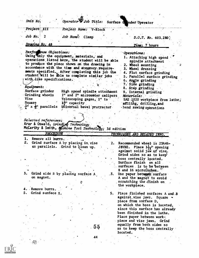
Unit No;
Project Name: -V-Block
job No. 2 job Nandi Clamp
Drapina No. 48
Ierfonce Objectives:Using nly the equipment, materials, andoperations listed here,.the student will be ableto prodUce the piece shown on the drawing inaccordance with the time and Steuracy,require-ments siecified. After completing this job thestudeneWill be ible t3 complete similar jobswith ike specifications.
'Operator (fob Title: Surface
D.O,T. No. 603.28C
Time: 7 hours
Equipment:
SUrface grinderGrinding wheelsViseSquareIP x -Ps' parallels4
High speed spindle attabhment1" and 2" micrometer calipersTelescoping gages, 1" to-ll" capacity2Universal beiel protractor.
Selected references:Krar & Oswald, Grindi TechnologyMcCarthy & Smith, chine Tool Technolab
mcpur
'Operations:
1. Attaching high speedspindle attachment
2. %%eel mounting3. Wheel dressing4. Flat surface grinding5. Parallel surface grinding6. Ang1e grinding7. Side grinding8. Step grinding9. Internal grindingMaterials:SAE Jpo workpiece from lathe;mrlling, drilling,and.band sawireoperations
; 3d edition
TECHNIQUES ANDAEMATED INPO.
Recommended wheel is 23A46-J8VBE. Place lie openingagaiRst solid jaw of visc.Grind sides so as to keep?boss centrally located.Surface finish on allsurfaces. is to be'hetween8 and 16 microindhes.Use paper betwn surfaceA and the magnet to avoidscratching the.finish on ,
the workpiece.
Place finished surfaces A and.B
1. Remove all burrs.2. Grind surface A by placing in.vise
on parallels. Grind to ean up.2.
*
3, Grind side B by placing surface Aon magnet.
.
4. Remove burrs.S. Grind surface X. 5.
55
44
againit,vise jaws. Square .piece from surface p,on which the boss is located,since this surface has alreadybeen finished in the lathe.Place paper between work-piece and vise jaws, Grindequally from both sides soas to keep the boss centrallylocated.
PROCEDURE TECHNIQUEWAND RELATED INFO.
6. Grind-surface Y by turning-piece averand placing surface-X on magnet.
7. Grind surface E.
S. Grind surface F.9. Remove burrs.10. Grind surface C to obtain the 11"
dimension.
11. Mount the high-speed spindleattachment and mounted wheel.
12. Grind side G of the 1/11" opening.Surface should be tangent to boredhole at the time that the A"dimension is reached.
13. Grindside J of the,1A." openinguntil a 1" step is detained.
14. Grind sift H of the 1A" openinguntil cokrect size is reached.
15. Grind side X of tkliklA"16. Side grind inside ar both 'of the 1"
steps until the 1A" opening isthick.
17. Remove burrs and all sharp e4m2s.18. Submit for inspection and graNk
5 6
45
7. Place piece in vise as instep 5 but tilted to'a 45°angle. Check angle settingby placing the protractoragainst the base of the viseand surface X. Grind surfaceuntil distance is obtainedas shown on the drawing.
8. Repeat the above procedure.9. Use mill file.10. Place in vise with surfaces
A and B against the jaws andsurface C protruding abovethe vise jaws. Square theworkpiece from side X.
11. 1" x 11", No. 23A46-MJVBE isrecommended. Dress wheel.
12. Place workpiece in vise withthe surfdres A and B againstvise javis and the open endprotruding from the side ofthe vise at least 1". Place1" block it the opposite endof vise so as to keep jawsparallel.
13. Workpiece is-t6 remain inthe same position as AA step 12.
14. Workpiece is to remain inthe same position as:.in step 12.
16. Dress'insi/e facelind undercutthe side.of theleounted wheel.
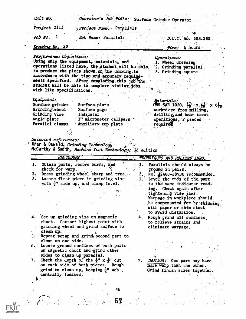
Vhit No.
Favject XIII
Job No. 1
Drowinc No. 50
Operator's Job Title: Surface Grinder Operator
Projmat Name: Parllels
Job Name: Parallels
Perforavice.
Using only theeqUipMentaterials andoperations listedjlerei,-the.,StP0Ont:Will beable.tOr produce the piece ShoWlnon:*hrawing4n:accordance with 'theitiSloand aqOuraOrrequilla'rnents Specified.- After'Conipleting'this jotrthe,
. student will be able to cOmplete siailirjObSwith like specifiCations.'
'D.O.T. NO. 603.280
)4:insti 6 hour's -
Operations:1. Wheel dressing2. Grinding parallel3.' Grinding square
.Equipment:
Surface grinderGrindinrwheelGrinding viseAngle plateParallel clamps
Surface plateSurface gageIndicator1" micrometer calipersAnxiliary top plate
Selected references:Krar & Oswald, Grinding Technolody
,
McCarthy & Smith, Machine Tool Technology; 3d edition
Matarias:aRs SAE 1020, '7"-x 25" X 61
, TT 17 72workpzece from milling,drilling,and heat treatoperations, '2 piecesrequir4
- PROCEDT1. Obtain parts, remove burrs, and
checkfor warp.2. Dress erinding wheel sharp and true. ,3. Locate first piece in grinding vise
with 4P side up, and clamp level.
4. Set up grinding vise on magneticchuck. Contact highest point withgrinding wheel and grind surface toclean up.
5. Repeat setup and grindpsecond part toclean up one side.
6. Locate ground surfaces of both partson magnetic chuck and grind othersides to clean up paraillel.
7. Check the depth of the 71.11 x r cuton each side of both pieces. Roughgrind to clean up, keeping i" web ,
centrally located.
46
TECHNIQUM9AND lgArEvlypio.
1. Parallels should always beground in pairs.
2. No,!,42A60-J8VBErecomnended.Level the ends of the partto the same indicator read-ing. Check again aftertightening vise jaws.Warpage in workpiece shouldbe compensated for by-shimming,with paper or shim stockto avoid distortion.
4. Rough grind all surfaces,.to relieve strains andeliminate warpage.
7. CAUTION: One part may havemore warp than the other.Grind finish sizes together.

. Locate first _piece ,o.Fprecisi,on.angle 'plate .anit .clajap", seCurely with :
,One- edge " , above 'top of plate.LiVel ends:with, an indicator ancl...'grind to clean. up. .
9. Repeat operation 8:on lecOnd.vpiece.'Locate both parts on magnetit chuckand grind opposite edges to _clean,-
11. Check the ..1", wide, undercut .and .
,...grind the parts,:to -clean up, ,keepingthe I" wide unZerce :centrally .
located. ..12.. Set ,up and dress 81" wide wheel.' .
13. LoCate both.'parta against back railof magnetic- chuCk ed to.end,`andgrind .i"..ondercut lo Clean up.
14.. Turn parts Over- aM..grind other. side of slot:.to.clean up:
15. Grind one end to clean up.
27? REL
V.
. .
14..RemoVe. burrs before.placingon magnetic chuck .
15. ClaMp. on ond to, an .angle .gate.Check-with 'a:square to makesure tlkat;the workpiece. is .verticali *.
Ttirn piece end for,end andcheck with sqliare to-niakesure workpiece is vertical.
.1.7. The auxiliary,top plate must ,
be ground in place beforeplacing workpieces on it,A.."diessed wheel and, lightgrinding cuts are esientialin finish' 'grindings parallels ,to avoid overheating, whichwould result in more 7Wdrpage.
16. Grind other end to 6" dimepsion.
17. Finish grind all four main stirfaceson each piece by placing on anauxiliary top plate.
18. Remove all shari; edges With astone and submit for inspectionand grade.
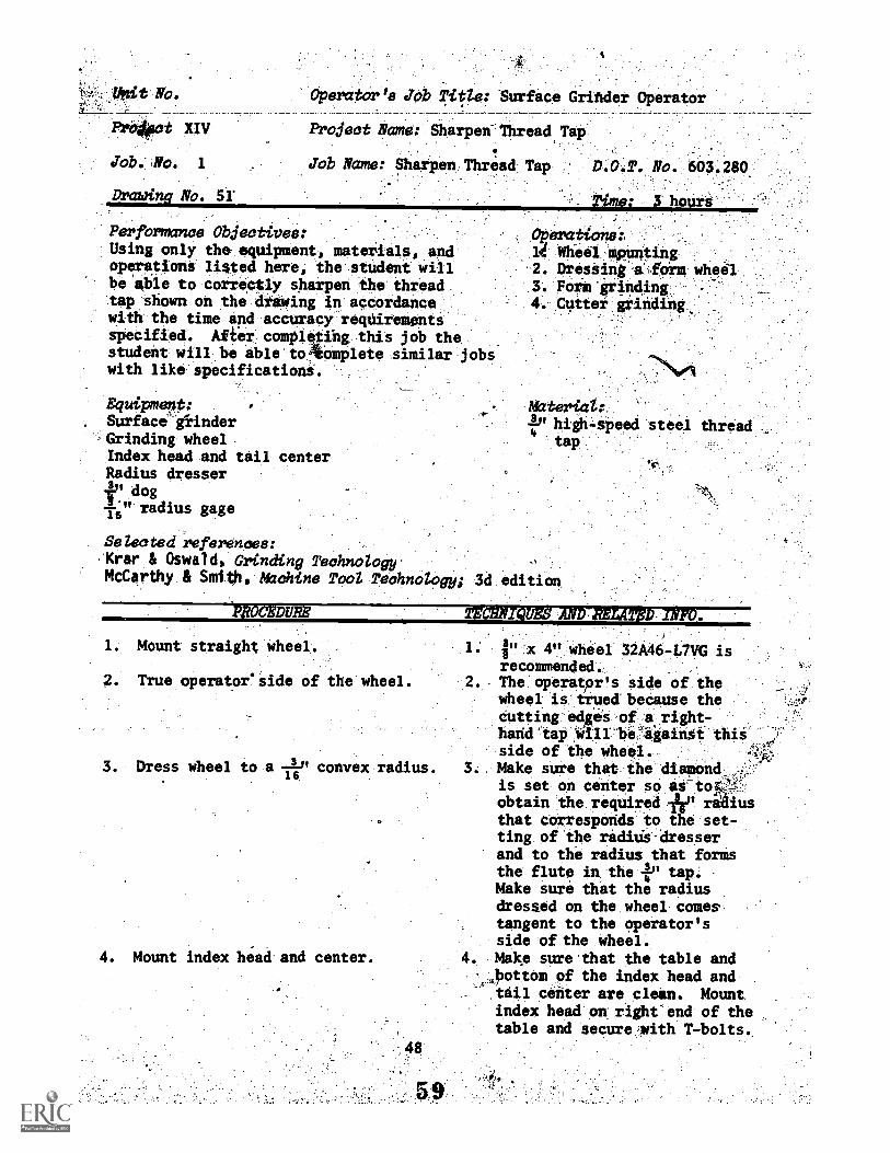
'fittit NO.
t XIV
No. 1Job.
Drawing No. 51
Operatorla Job Title: Surface Grinder Operator
Project Name: Sharpen...Thread Tap
Job Name: Sharpen.Thread Tap
Performance Objectives:Using only the equipment, materials, andoperations listed here, the student willbe able to correctly sharpen the threadtap shown on the drawing in accordancewith the time arid accuracy reqUirementsspecified. After completing this job thestudent will be able to *omplete similar jobswith like specifications.
Equipment:Surface' OinderGrinding wheelIndex head and tail centerRadius dresserf' dog--'" radius gage16
Selected references:Krar & Oswald, Grinding TechnologyMcCarthy & Smith, Machine Tool Technology;
D.O.T. No. 603.280
Time: 3 hours
OperatioMsi1.4 Wheel !splinting
DresSing .alorm wheel3. Foxin'grihding,4. Outtei grinding
Material:,1" high-speed steel thread4 .
tap
1. Mount straight wheel.
2. True operator' side of the wheel.
3. Dress wheel to a -116 -" convex radius.
4. Mount index head and center.
x 4" wheel 32A46-L7VG isrecommended.
. The operatpr's side of the .
wheel is trued because thecutting e4ges of a right-
. . . A Ahand tap will be againOt thisside of the wheel.
3. Make sure that the diamondis set on center so as-tow$obtain Ithe required -ik" raaiusthat corresporids to the set-ting of the raditis dresserand to the radius that formsthe flute in the ,401 tap.Make sure that the radiusdressed on the wheel comestangent to the operator'sside of the wheel.
. Make sure that the table andottom 9f the index head andtail center are clean. Mountindex head on right-end of thetable and secure ,with T-bolts.
,
PROcED
2_131ace . taR.hitrieeni centers with...
dog attached to shank.
-
TgaiNiQUES AO RH V 2100.
- - 5. -'=_,Make: tiara- that- the -dog. is
.secUre in.;the.slot.:,in the
.index. head.:::: (Taps. Without'ceater -ht4ea are to-be heldin collet's:) ..' : ,. .
.Retate.4007104 tPinclke .
-an4 tap, se.. efra ' on the
wheel will falt.inace inthe .fluteofthe tap PA' ...
.,
the 'operator7aide4, ., he
wheel.' ThiS44.4 She''vi,that
.the side eilc'-..44-.;41leer ia. irconalderahl.e.-114taAisofft.'aelAilrom .tli*--040x-44d.thUS.resultitig in the saeleangl that Was originally'''. -'
'..i.. otna.-. peiigtia"-7 a' ''t;arerse I. . .
stops -bef
CAUTION,: sientclearance: bet&en the wheel.
ard :and 'itit,:dou'at Ole? end. .. ....., he! triversai' ,, . '.. ;-For each:cut: along the faCe
400,the tipAeeth, - rieovi,- thVAahle ewer fram!the,operator
. A noibrep :.thalit.-0O t. per cut.After -tieh' 0045V:?cutAindex,,fcirsthe nexi4140:. -After'
,,-eceldh.., le'te cyae Oi .retr-olut move e table
front4- atim another..0005'c fcir next cut 'du
each fl' tezt.. Rèpeat. .tmtli 'tap
4:s sharp
:UsP 499.1.01t to avoid b-. tap!! `'. R. .`-'ss t e wheel as
rieedid) t maintai, a Ewe... ..IICutting wheel' and, p obtain-0 , '
. '' a surface finish 8.to- i6,
mi'crbiffehes.' ' . .
-...
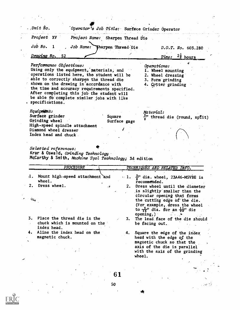
Unit *o.
Project XV
41
Project Name: Sharpen Thread Liie
harpen Thread:Die
'Operator's Job TitZe: Surface Grinder Operator
Job No. 1 , Job Name:
Drawi N . 52
D.O.T. No. 603.280
Time: 2i hours
Performance Objectives:Using only the equipment, materials, andoperations listed here, the student will beable to correctly sharpen the thread dieshown on the drawing in accordance withthe time and accuracy requirements specified.After completing this job the student willbe able co complete similar jobs with like
. specifications.
Equip0Oht:Surface grinderGrinding wheelHigh-speed spindle attachmentDiamond wheel dresserIndex head and chuck
SquareSurface gage
Operations:1. Wheel mounting2. Wheel dressing3. Form grinding4. qp;ter grinding
Material:lb' thread die (round, sp/it)8
Selected references:Krar & Oswald, Grinding TechnologyMcCarthy & Smith, Machine Tool Technology; 3d edition
PROCEDURE TECHNI UES AND RELATE INFO.'
a. Mount high-speed attachment d 1.
wheel.2. Dress wheel. 2.
3. Place the thread die in thechuck which is mounted on theindex head.
4. Aline the index head on themagnetic chuck.
-)
6150
3.
lb' dia. wheel, 23A46-M5VBE isrecommended.Dress wheel until the diameteris slightly smaller than thecircular openink that formsthe cutting edge of-the die.(For example, dress the wheelto Ile' dia. for an Aik dieopening.) .4
The lead face of the die shouldbe facing out.
Square the edge of the indexhead with the edge of themagnetic chuck so that theaxis of the die is parallelwith the axis of the grindingwheel.
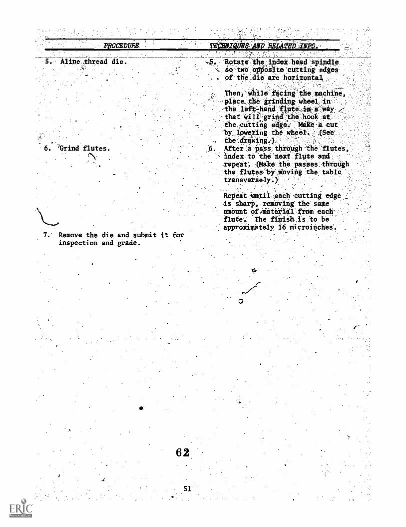
PROCEDIM lEdlilYzQthig441) .414TE11
Aline thread die.
trind flutes.
Rotate thijiidex head spindleso two opposite cutting edgesof the.,die are horizontal, ,
Then w6le 'facing the machine
Place the grinding wheel 17n-the fiute Way,
that will grind the.hook at, .the cutting edge: Mike 'a cut
by lowering the Wheel. (See
the .draWing.)
After a Pass through the flutes,index to the next flUte andzepeat. (Make the passes throUghthe flutes ty moving the tabletransversely.)`
7. Remove the die and submit it forinspection and grade.
62
Repeat _until each cutting edgeis sharp, removing the sameamount ofimaterial from eachflute. The finish is to beapproXimately 16 microinches'.
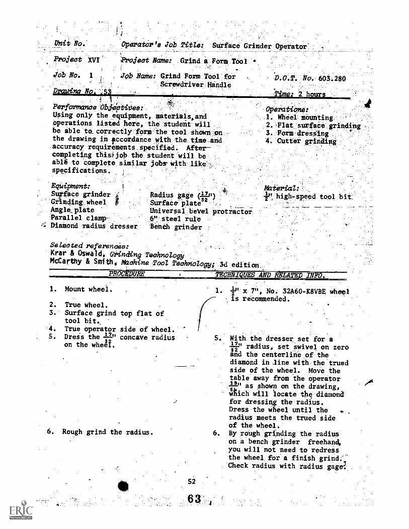
Unit No.
Project XVI'
Job No. 1
Drawina Na. .54
;
Performance Obileptives:Using only the equipment, materials,.andoperations listed here, the student willbe able to correctly form the tool shown onthe drawing in itccordance with the time andaccuracy requirements specified. Aftercompleting thieijob the student will beable to complete similar jobs with likespecifications.
4
Operator's Job Title: Surface Grinder Operator 4
Project Name: Grind a Form Tool
Job Name: Grind Form Tool forScrewdriver Handle
EquipMent:Sufface grinder kGiinding1 wheel fAngle,plateParallel clampDiamond radius dresser
No. 603.280 :
Time: 2 hours
OPeratione:1. Wheel mounting .
2.-Flat surface grindIng3. Form dressing4. Cutter grinding
Radius gage (+1.11)
Surface plateuniversal beVel protractor.6" steel ruleBench grinder
Selected references:Krar & Oswald, Grinding TechnologyMcCarthy & Smith, Machine Tool Techriology; 3d edition
Materica:40, high-speed tool bit
PROCEDURE TECRNI UES.AND RELATED INFO.
1. Mount wheel.
2. True wheel.3. Surface grind
tool bit,4. True operator5. Dress the 22"
on the when.
top flat of
side of wheel.concave radius
6. Rough grind the radius.
1 x 7" No- 32A60-K8VBB wheel. , .
, is recommended.
5. With the dresser set for a-12-" radius, set swivel on zeroszand the centerline of thediamond in line with the truedside of the wheel. Move thetable away from the operator-Lb' as shown on the drawing,w ich will locate the diamondfor dressing the radius.Dress the wheel until theradius meets the trued sideof the wheel.
6. By rough grinding the radiuson a bench grinder freehand,you will not need to redressthe wheel for a finish grind;Check radius with radius gage'.
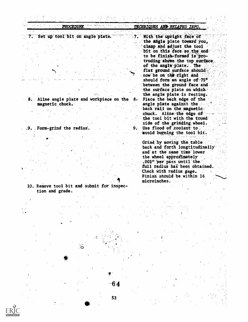
-PROCEDURr milizators 40aszi4TED INFO.
T. Set up toor-bit on angIO plat& -7. With the upright-ii6,--$5-f-the 01104 plate toward you,-clamp and adjust the toolbit on ibis face.S0,tha,end-to be finish-formed ls OTO-
trudinglib0e, the toP surfaceof the anglelqato. The
,.. flat grOund surface shoul7 now be on thii right and
should form an angle of,75°between the ground face andthe surface plate on-whichthe angle plate is resting.
. Aline angle plate and workpiece on the 8. Place the back edge of theangle plate against theback rail on the magnetic.chuck. Aline-the edge of -the tool bit with the truedside of the grinding wheel.
orm-grind the radius% 9. Use flood of_coolant toavoid burning the tool bit.
Grind by moving the tableback and forth longiitudinally'and-at the same time lowerthe wheel'apProgimately.001" "per pass until thefull radius hai been obtained.Check with radius gage.Finisn should be within 16microinches.
10. Remove tool bit and submit for inspec-tion and grade.
magnetic chuck.
4
53
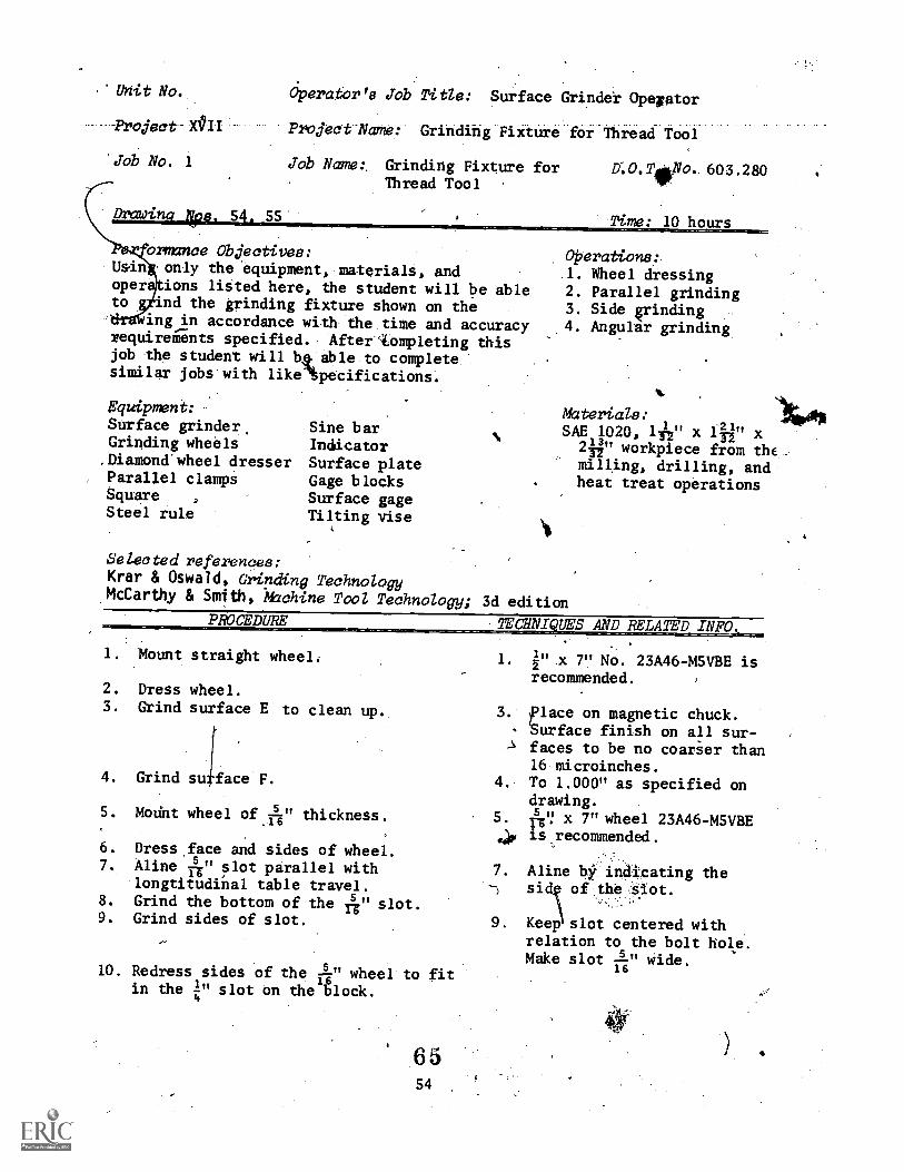
Unit No.
-Project X0II
Job No. 1
Drawin SS
Operator's job Title: Surface Grinder Opegator
Project Name: Grinding Fixture for Thread Tool
Job Name:. Grinding Fixture for D:O.T No. 603.280Thread Tool
Time: 10 hours
ormance Objectives:Usin only the equipment, materials, andoper ions listed here, the student will be ableto ind the grinding fixture shown on the
ing in accordance with the time and accuracyrequirements specified. AfterAompleting thisjob the student will b4 able to completesimilar jobs with like'4ecifications.
Equipment:Surface grinder,Grinding wheelsDiamond'wheel dresserParallel clampiSquare ,
Steel rule
Sine barIndicatorSurface plateGage blocksSurface gageTilting vise
operations:1. Wheel dressing2. Parallel grinding3. Side vinding4. Angular grinding
mterials:
SAE 1020, 141'1" x 144" x2" workpiece from the_mi4ing, drilling, andheat treat operations
Selected references:Krar & Oswald, Grinding TechnologyMcCarthy & Smith, 'machine TooZ Technology; 3d edition
PROCEDURE TECHNIQUES AND RELATED INFO,
1. :Mount straight wheel,
2. Dress wheel.3. Grind surface E to clean up.
4. Grind su face F.
5. Mount wheel of A." thickness..26
6. Dress,face and sides of wheel.7. Aline A" slot parallel with
longtitudinal table travel.8. Grind the bottom of the A" slot.9. Grind sides of slot.
10. Redress sides of the s" wheel to fit16
in the 1" slot on the block.4
6 554
1. 1" x 7" No 23A46-M5VBE is2recommended.
3. place on magnetic chuck.Surface finish on all sur-faces to be no coarier than16 microinches.To 1.000" as specified ondrawing.
x 7" wheel 23A46-M5VBEis,recommended.
Aline bir indicating thesi of the slot.
Keep1
4.
5.
7.
9. slot centered withrelation to the bolt hole.Make slot
6wide.
1
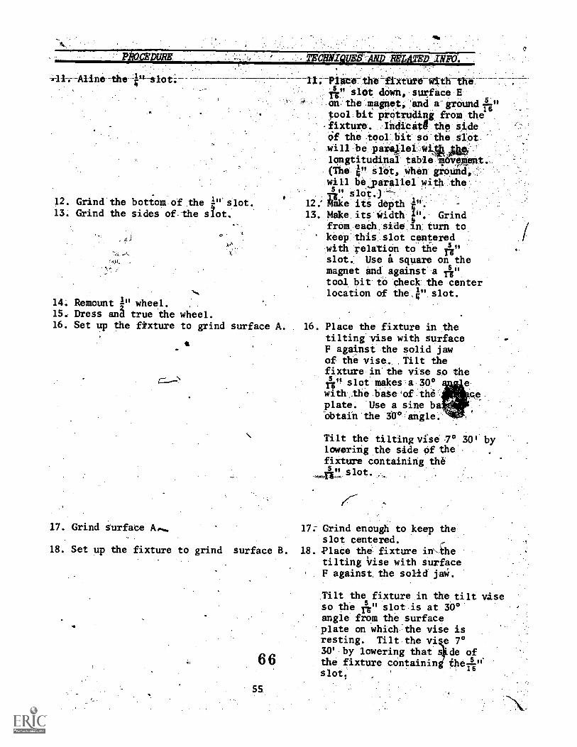
P CE1FIFRE,
.-11.--AHne -the V--Slot:;--
TECHN2WES ANp REZATED INFO.
11:-Piece the--fixtute- with theA" slot down, surface Eon the magnet, 'and a groundtool bit protruding from the-fixture. Indio stg the sideOf the tool bit so the slotwill be parapeliongtitudinil table'm6v90ent(The 4" slot, when ground,
with the
12.' Make its depth t".13. Make its Width I". Grind
from each side in turn tokeep this slot centeredwith relation to the Auslot. Use a square on themagnet and against a rsg"tool bit to check the centerlocation of the.4" slot.
12. Grind the bottom of the ''ul' slot.
13. Grind the sides of the slot.
z
14. Remount ,1" wheel. ,
15. Dress and true the wheel.16. Set up the fixture to grind surface A. 16. Place the fixture in the
tilting vise with surfaceF against the solid jawof the vise. Tilt thefixture in the vise so the
5 " slot makes a 300 ewith .the base of theplate. Use a sine ba'obtain the 300 angle.
Tilt the tilting vise .70 30' bylowering the side of thefixture containing the
slot.
17. Grind Surface A', 17; Grind enough to keep thslot centered.
18. Set up the fixture to grind surface B. 18. lace the fixture in-thetilting Vise with surfaceF against the solid jaW.
Tilt the fixture in the tilt viseso the A" slot is at 30°angle from the surfaceplate on which'the vise isresting. Tilt the vi e 7030' by lowering that s'de of
6 6 the fixture containinslots
16
55
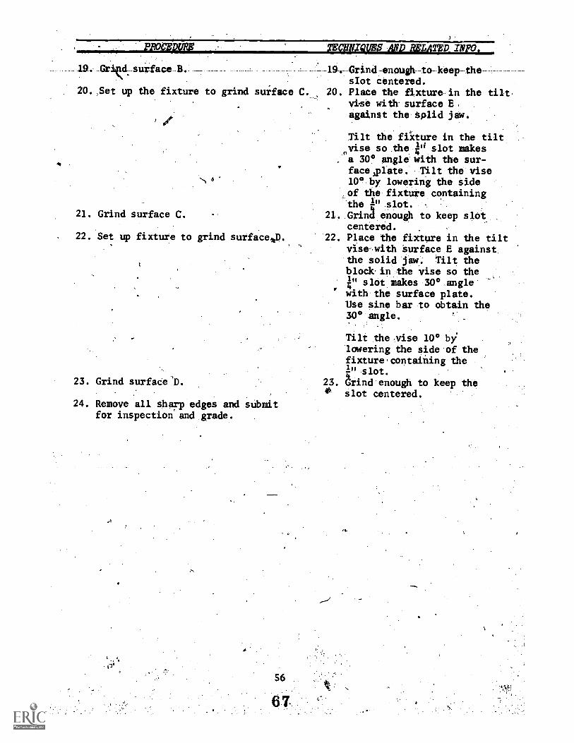
PROOIDLIFS
19. Gritk.surface B. --
20.,Set up the fixture to grind suiface C.
21. Grind surface C.
. 22. Set up fixture to grind surfacelp.,
23. Grind surfaCe D.
24. Remove all sharp edges and submitfor inspection and grade.
TEOHNIVES AND RELATED INFO.
-19. Grind-enough-to-keep-theslot centered.
20. Place the fixture in the tilt.vise with surface E,against the Solid jaw.
Tilt the fixture in the tiltvise so the e slot makes
a
a 30° angle with the sur-faceplate. Tilt the vise10° by lowering the sideof the fixture containingthe 1" slot.
21. Grind enough to keep slotcentered.
22. Place the fixture in the tiltvise-with Surface E againstthe solid jaw. Tilt theblock in the vise so theI" slot makes 30° angle-
, 4with the surface plate.Use sine bax to obtain the30° angle.
Tilt the vise 100 bylowering the side of thefixture,containing the1" slot.
23. Grind enough to keep the0 slot centered.
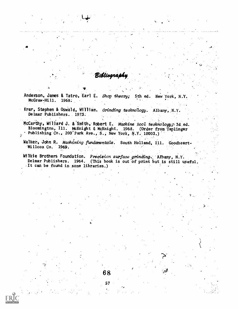
swarm*
Anderson, James & Tatro, Earl E. Shop theory; S,th ed. New York, N.Y.McGraw-Hill. 1968;
Krar, Stephen & Osviald, William. Grinding technology. Albany N.Y.Delmar Publishers. 1973.
McCarthy, Willard J. &'Smithl.Robert E. Machine tool technoLogyp3d.ed.Bloomington, Ill. McKnight 4 McKnight. 1968. (Order from Taplinger
. Publishing Co., 200'Park Ave., S., New York, N.Y. 10003.)
Walker, John R. Machining Andamentals. South Holland, Ill. GOodheart-Willcox Co. 1969.
Wilkie Brothers Foundation. Precision surface grinding, 'Arbany, N.Y.Delmar Publishers. 1964. (This book is out 'of print iiut is still upeful.It can be found in some libraries.)
6 8
6 9
58
10,
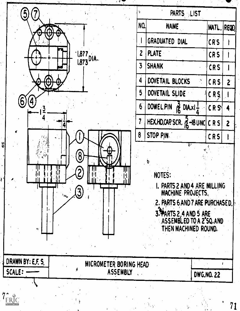
I 877 ,
1.873
4.
PARTS LIST
NO. NAME MAIL. RECO,
I GRADUATED DIAL CRS I
2 PLATE
3 SHANK
CR 'S
4 DOVETAIL BLOCKS
11
C R S
C R S
5 DOVETAIL SLIDE
6 DOWEL.PIN DIA.xIi
7 HEKHO.CAP SCR.6
-18 UNC
8 STOP PIN.
C
C R
C R S
C R S
0
NOTEt.
I. PARTS 2 AND 4 ARE MILLING
MACHINE PROJEcTS.
2. PARTS 6, AND 7 ARE PURCHASED.
NRTS 2_,4 AND 5 ARE
ASSEMbLED TO, A 2"SQ.AND
THEN MACHINED ROUND.
DRAWN BY: E,F. S.
SCALE: T-A%
70
MICROMETER BORING HEAD
ASSEMBLYDWG.NO. 22
71
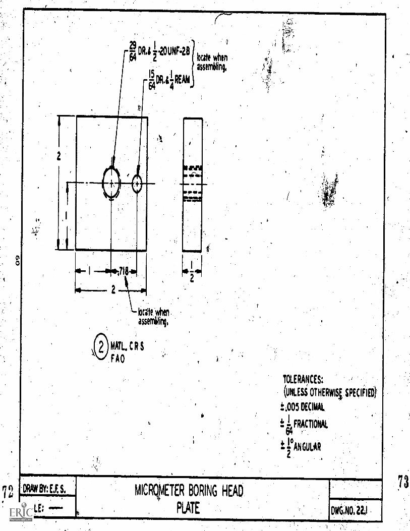
72
29 IDR.L UNF-28
64
15 IREAM
64 4
2
MATL, C
F AO
locate when
assembling,
locite when
assemiling,
TOLERANCES:
(UNLESS OTHERvast SPECIFIEO
±.005 DECIMAL
FRACTIONAL, 64
t PAN GULAR2
'DW8Y:E.S,
SCALE: -0
MICR/METER BORING HEAD
PLATE DIV6.NOILI
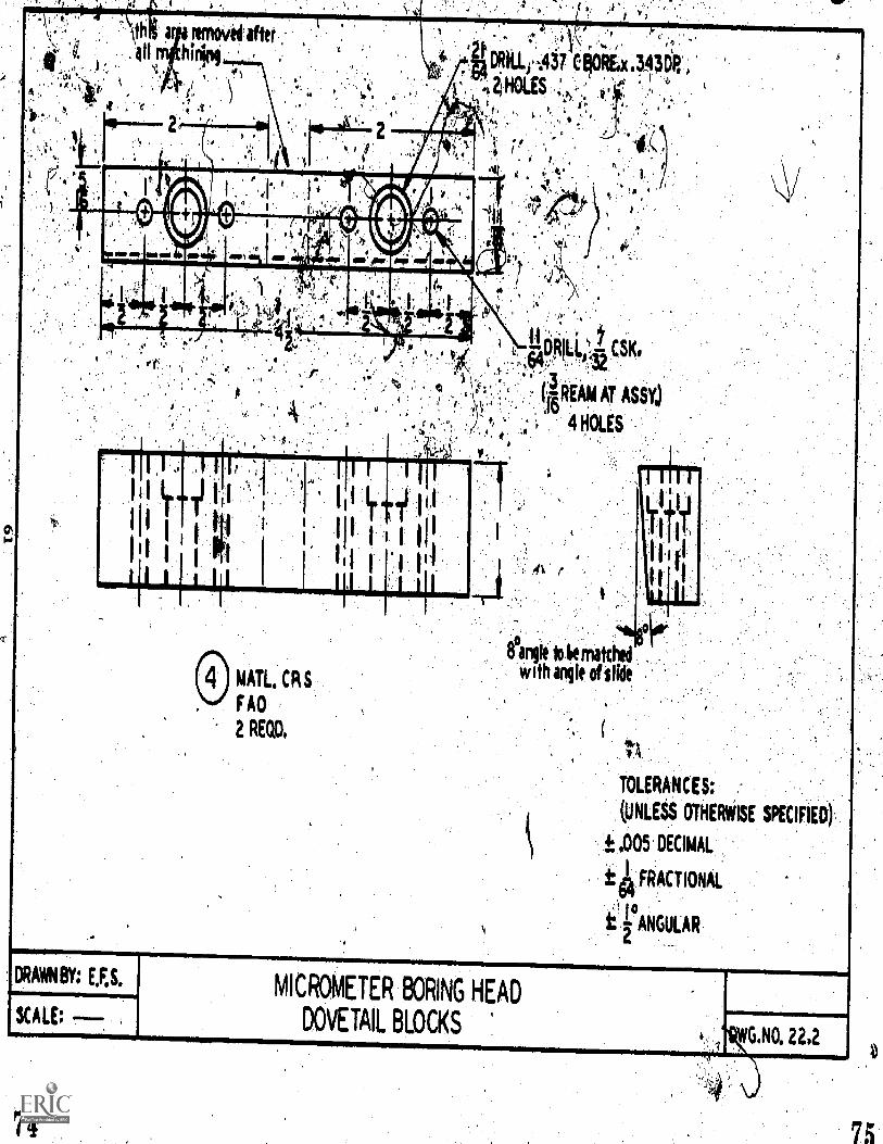
:
Alt
P
MOP UR Mal= 411, Or A AID
TOLERANCES:
(UNLESS OTHERWISE SPECIFIED)
t ,005.DECIMAL
t FRACTIONAL
NGUA LAR
DRAWNBY: E,F,S.
SCALE:
MICROMETER BORING HEAD
DOVETAIL BLOCKS'WG.NO. 222
74 75

76
*20 UNNA HEX,x1DP16 8
4(BROACH)
45°CHAM.32
.502
498 DI
NO,21 DR,
THROUGH
,990 DIA,
3
UNFiA
Ix I16
UNDERCUT32 ,
50249801A,
I
28 32 45wCHAM.
SHMAITT!C R
FAO
rm,
CE INDEX
0 DIVISIONS
TOLERANCES:
DIAL(UNLESS OTHEFNSE SPECIFIED)
MAIL, CRSt.005_ON DECIMAL DIMENSIONS
CASE HARDENON FRACTIONAL DIMENSIONS
64
tr ON Ai6ULAR 0IMENS104
27 0-0-TO FIT7 UNDERCUT
STOP PININ DIAL,
MATLDR.ROD HARDENED
FAO
DRAWN BY : E,F,S.
SCALE
MICROMETER BORING HEAD
DIAL, SHANK,AND STOP PINDWG.N0,0
77
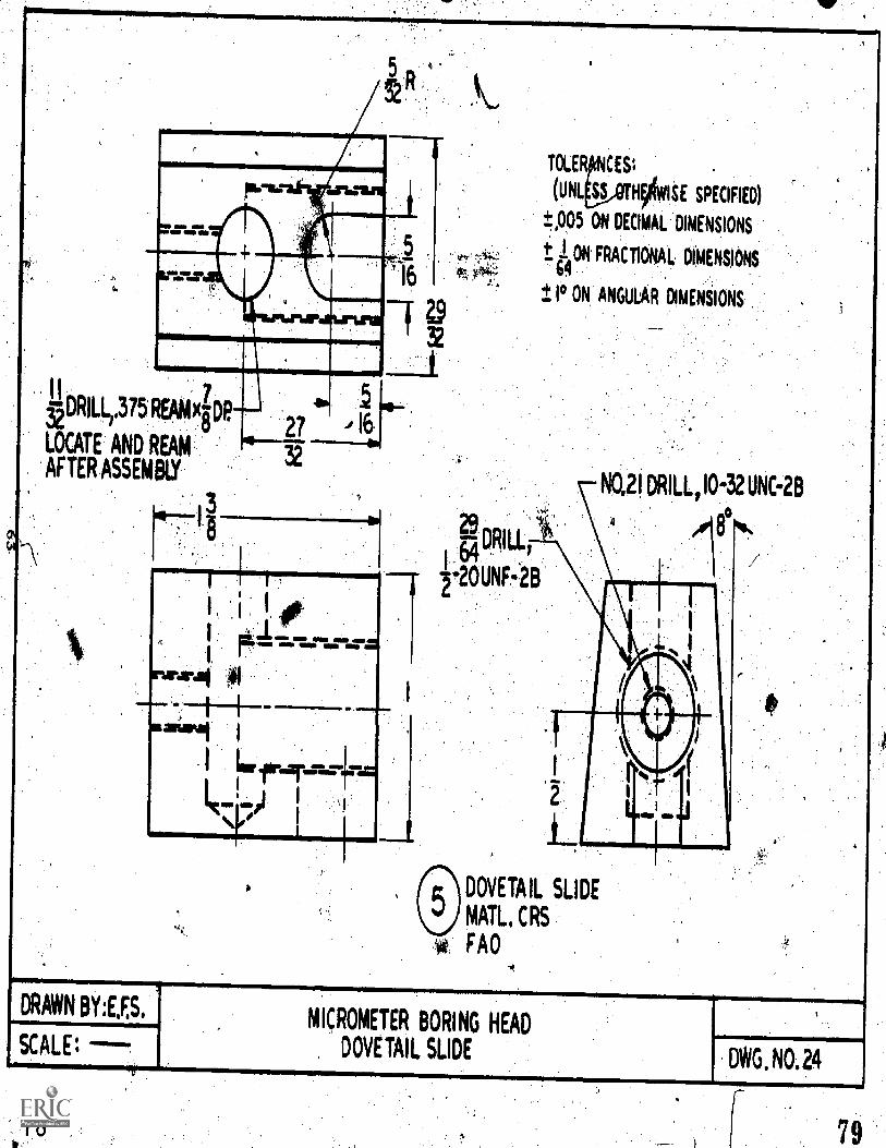
1110
II T..DRILL,375 REMAIN?
LOCATE AND REAM
AFTER ASSEMBIY
27
t
I I
I .I, 12.
rursal
salmi I
Le fir.Taurirga
/1""I'"Pi I
\11' I
TOLER CESt
(UK NOISE SPECIFIED)
±P05 ON DECIMAL DIMENSIONS
± I ON FRACTIONAL DIMENSIONS64
± I° ON ANGULAR DIMENSIONS
NO,21DRILL,10-32UNC-2B
DRILL64 /
-20UNF-2B
Lnik'
DOVETAIL SLIDE
MAIL, CRS
FAO
DRAWN BY:E,F,S,
SCALE;MICROMETER BORING HEAD
DOVETAIL SLIDEDWG. NO.24
79
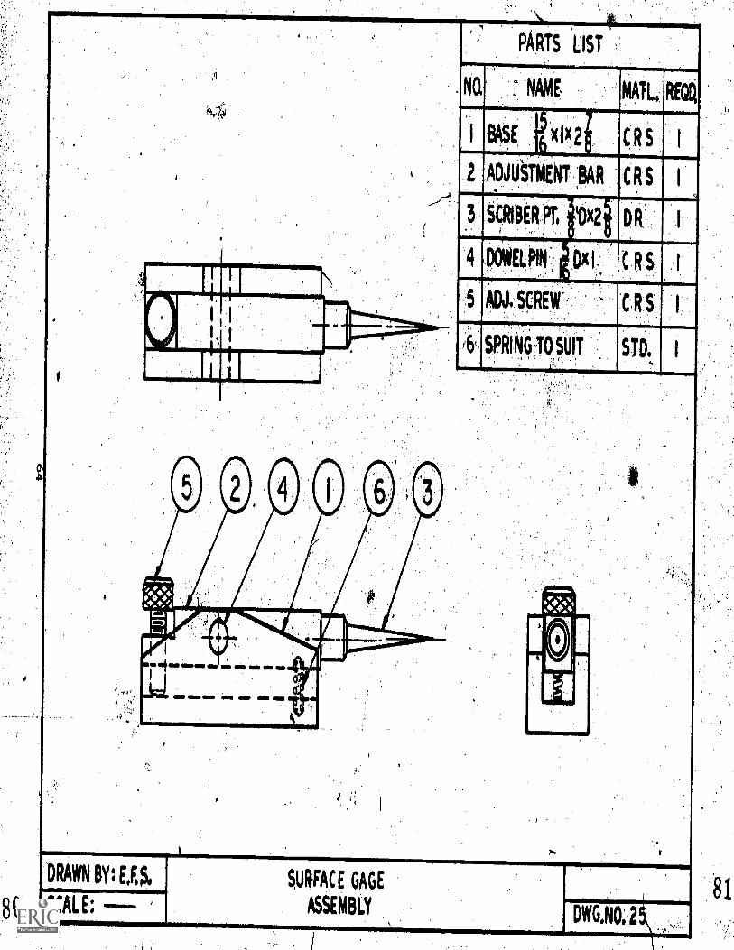
NO.
PARTS LIST
NAME
BASE x
,ADJUSTMENT ;BAR
MAIL REGO
CRS
R S I
SPRING,TO,SUIT
DRAWN BY: LES.
SCALE. - SURFACE GAGE
ASSEMBLYDWG,NO, 2
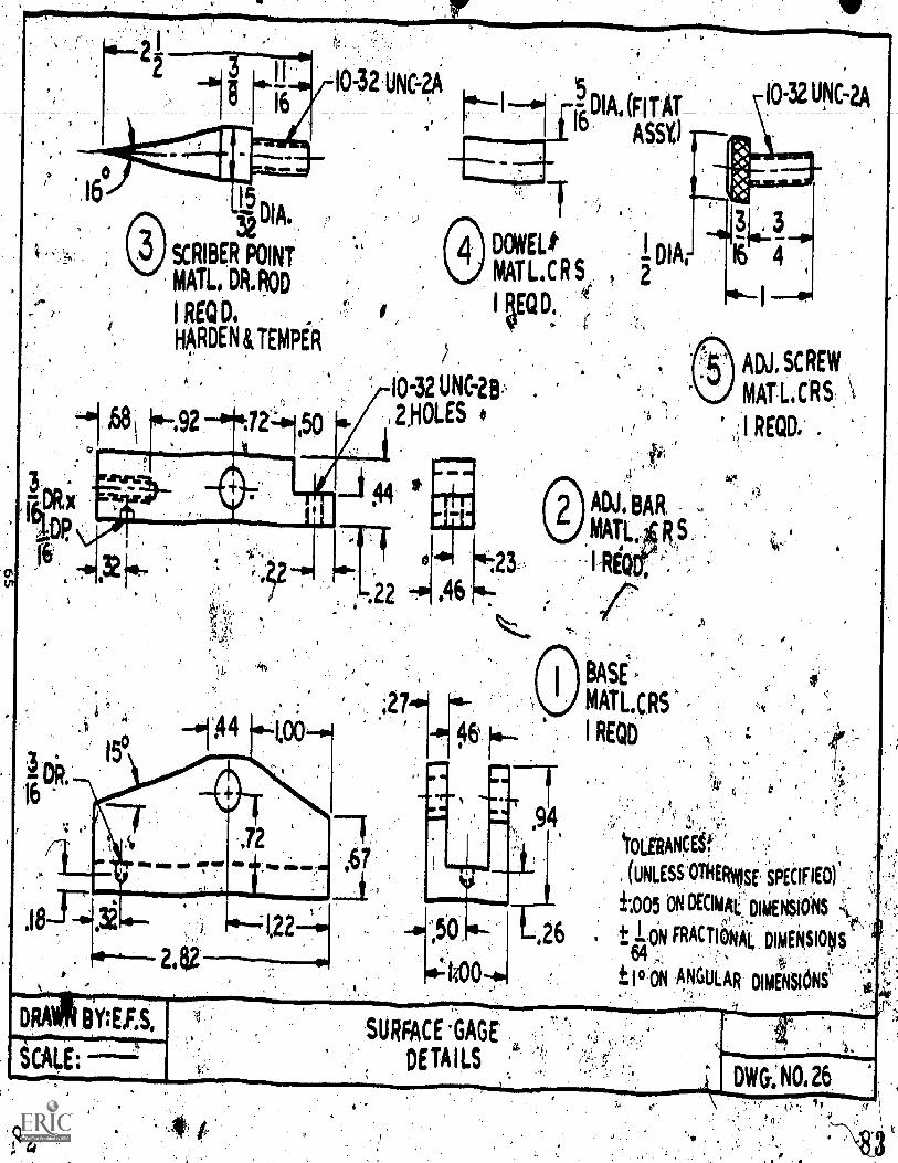
0-32 UNC-0kDIA. (FIT AT'° ASS%)
IJ DIA.32
RIBER POINT
MAIL DR.ROD
I REGD.
HpDEN&TEMPER
,6131 0-,92
(1,4 DCWEL,
MATL.CRS
5EQD. kjf
,
1.0-32 UNC-213, .
2,HOLES 4
ADJ. BAR
MAT14
/3/4
BASE
MATLCRS
I REOD
ADJ. SCREW
MAIL CRS \I REQD. .
,1
4r0LeRANEif.
(UNLESS OTHERVusf, SPECIFIEO)'
±;005 ON Malik DliENS1ONS
t ION FRACTIONk DIMEkSIOS
t 10 oN A,NGULAR DIMENSIoNS' crei;
7:: 'I.
DWG: N0,26
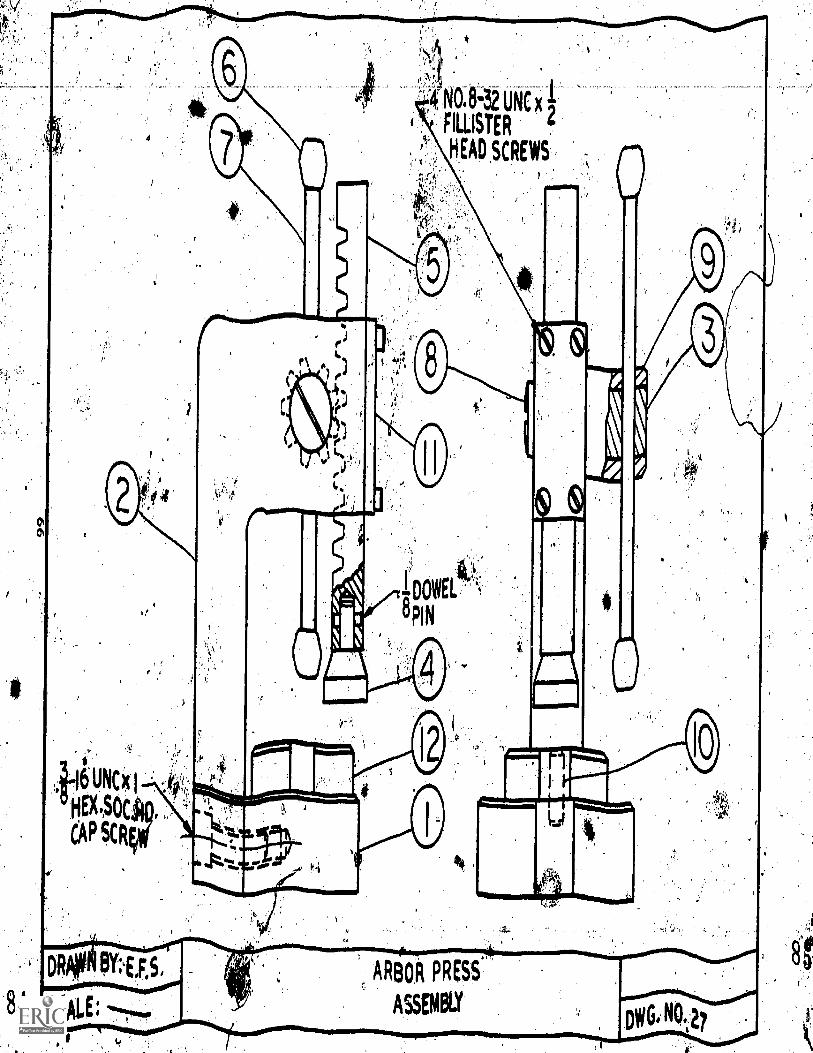
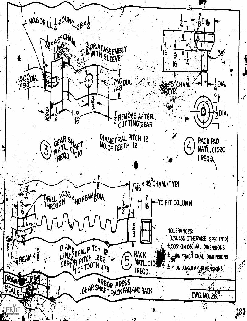
36
50901A,.490
efAR Ski 4,
64(;TROD, 'OP
REMOV,4FTER..
CUT11NGGEAR
DIAmo:RAL PITCH 12
No.OF TEETH 12
4 7
EAMPIA,
0x 45. CHAM. (TYM
16
TO FIT COLUMN7
6
DIA.
RACK PAD
MA. C1020
1 REQD
TOL ERANC ES:
(UNLESS OTHERWISE SPECIFIED)
:1405 ON DECIMAL DIMENSIONS
i.thON FryiCTION'AL, DIMENSIONS.
I° ON A.NPULAR sigys.$.,.
I DWG,N0.2E1
4 V.$
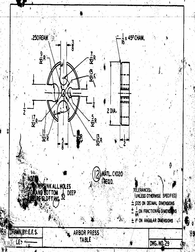
1
144.
4,4
R
0
.4
NK ALLH ES
T TOM DEEP
04.1
Pt'
14
4
2 DIA
49CHAM16
ATL, CI020
EQ D.
BY: E. S. ARBOR. PRBS
TABLE
4
LOANCES;-.
(UNLESS. OtHER14.11SE PECIFIEO)
±...,005. DE.CIMALOOENSIONS
- i;
64/.ANCOR *IONS
G N
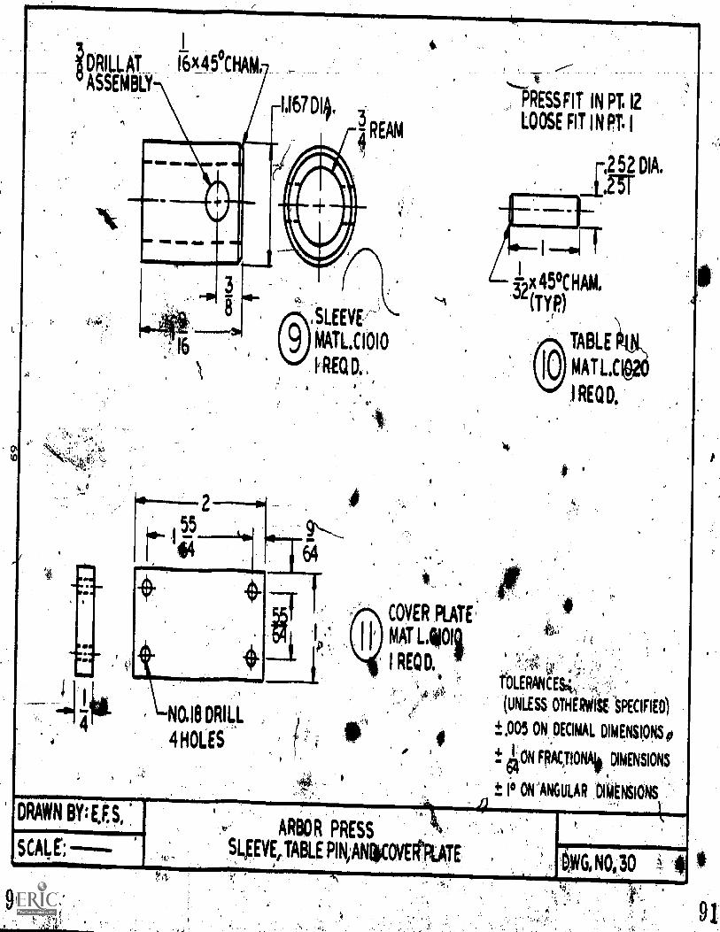
DRILL AT 16)4a 5-CHAM
ASSEMBLY
-1167 DI4.
1 MIS OM NM
MD WO UM NOS
;'.'
..Aji.
NO.18 DRILL
4 HOLES
SLEEVE:-
MATLC1010
REQ ,
,
. 0
PRESS FIT IN PT. 12
LOOSE FIT IN PT. 1
r,2 52 DIA.
.1,23T
1,x 45°C HAM.
"(TY,P)
TABLE
MAT LiC
I REQD,
COVER PLATE'
MAT L.ligOli
I REQD,
DRAWN BY: S,
0
ARBOR PRESS
sigvEtTABLE PIN,ANWOVE 'RATE1}WG, NO.30
r $ {TOLERANCE4 .
(UNLESS OTHERVIS SPECIFIED)
.005 ON, DECIMAL DIMENSIONS
4ON RACTIONA ,DIMENSIONS
1.° ON 'ANGULAR DIMtNSIONS
'
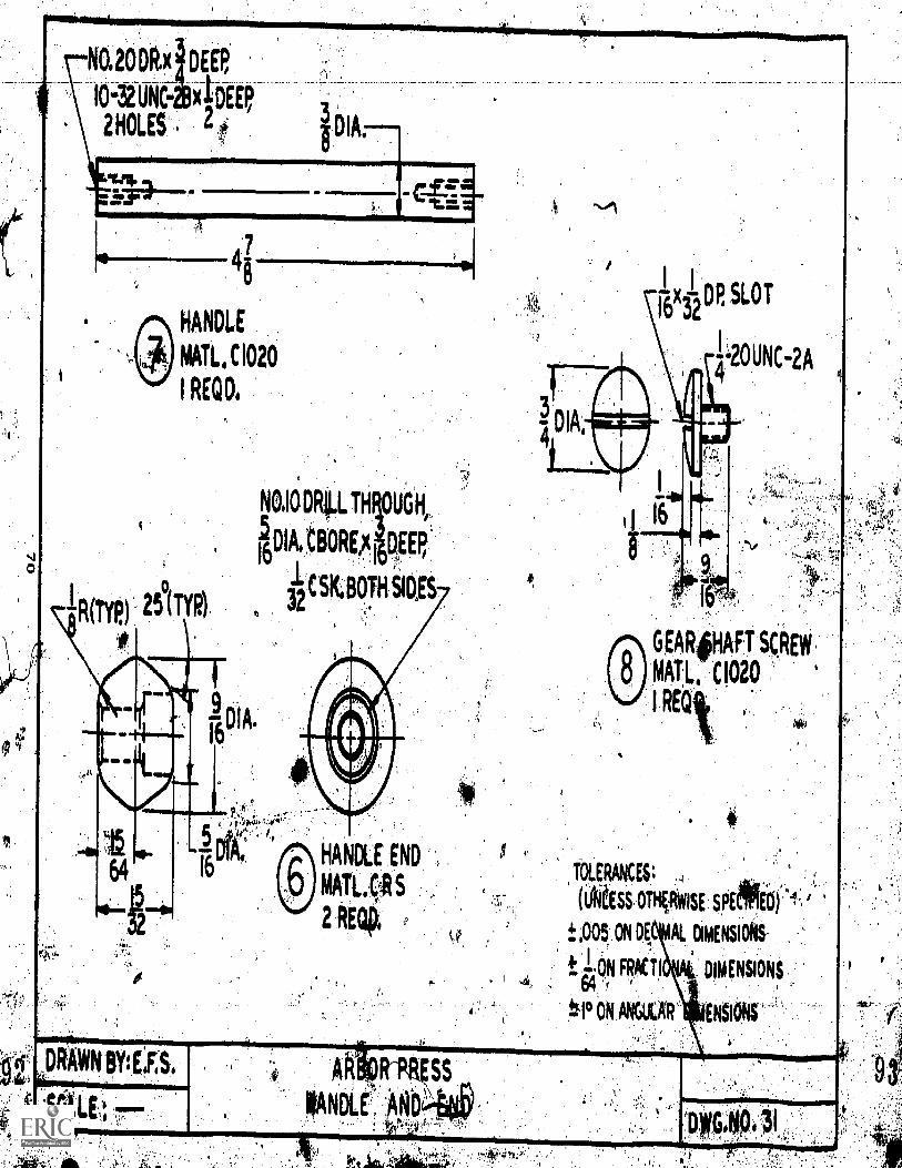
suoDRA DER
.10-3ZUNC xi,DEEP
L0 .
41
HANDLE
MAIL, C1020
I REM
I 1
16x DP SLOT
32
I--2OUNCiA
a
NO.16DRILTH OUGH,
D1A.tBOREAI
DEEP'16 , '
CSK,BOTH SIDES322?(TYlii
TOLERANCES;
(iiiiESSOTHOWISE SOEME4
pa5, ON DE, AL DIMENSIONS.
FRACTI DIMENSIONS
#.1° 01.1 AkULAR' ENSIONS'
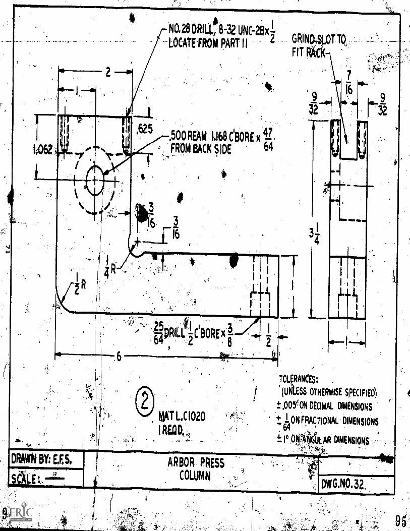
Na 28 DRILL, 8-32 UNC-213x -LOCATE FROM PART II
2 GRINpySLOT TQ,
FIT RAO
TOLERANCES:
(UNI.ESS OTHERWISE SpECIFIED)
.0(WON DECIMAL DIMENSONS
ON 'FRACTIONAL DIMENSIONS
/Ci.°Piet4LAR DIMENSIONS
ARBOR PRESS
COLUMNDWG.N0.32.
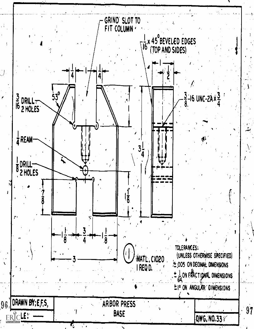
3 DRILL
162 HOLES'
GRIND SLOT TO -
FIT COLUMN
j.
4eBEVELED iDGES
1° (TOP AND SIDES)
REAM
DRILL
" 2 HOLES
Om.
'4
amp MsMO MI al9M
MP ft
°MAIL, CI020
I REQ O.
e
DRAWN BY; EIRS, ARBOR PRESS
SCALE: BASE
1.1
3116 UNC-ZA 38, 4
'
)
TOLERANCES:
(UNLESS OTHERWISE iRECIFIED)
4005 ON DECIML MANSIONS
,tONIe1IJNA1. DION.SIONS
I° ON ANGULO' 014EN'SIONStr,
OVIGi NO.33
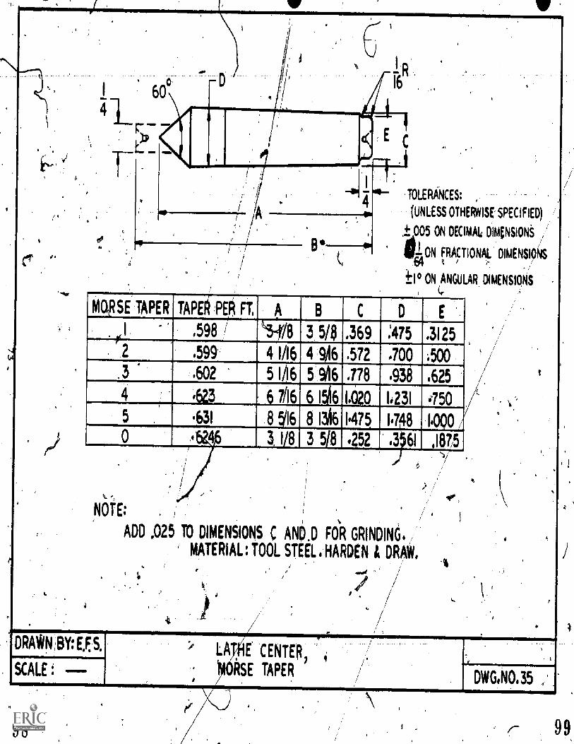
ATiv
C.41
TOLERANCES:
(UNLESS OTHERWISE SPECIFIED)
tA005 ON DECIMAL DIKNSIONS f,
gi ON FRACTIONAL DIMENSIOS4I ° ON ANGULAR DIMENSIONS
MORSE' TAPER TAPE§ P R Ft B C
'.3I.598 -*/8 13 5/8 .L369 :475 25
.599 4 1/16 4 9A6 .572 .700,
.602 5 1/16 5 %16 .778 938 .625
i23 6 7/16 6 I 6 1.020 1.231 i.750
.631 8 51I6 8 1516 ,I.475. I7 8 100 /. 0 16246 3 1/8 3 518 .252 .3 61 4187,5
,NOTE:
DRAWN BY:E,ES.
TALE :
ADD ,025 TO DIMENSIONS C ANO.D FOR GRINDIN6.
MATERIAL: TOOL STEEL, HARDEN & DRAW.
4
LATOE CENTER,
,fORSE TAPERDWG.N0.35
A
Avid
98 99
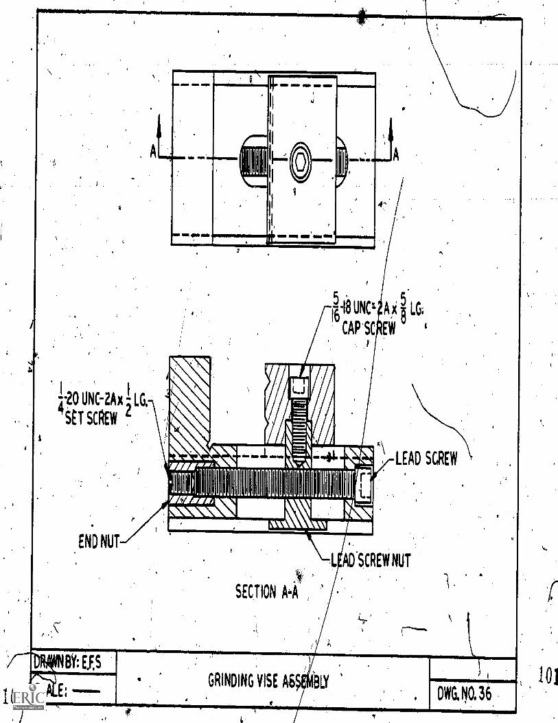
Ii
,
,
1 0
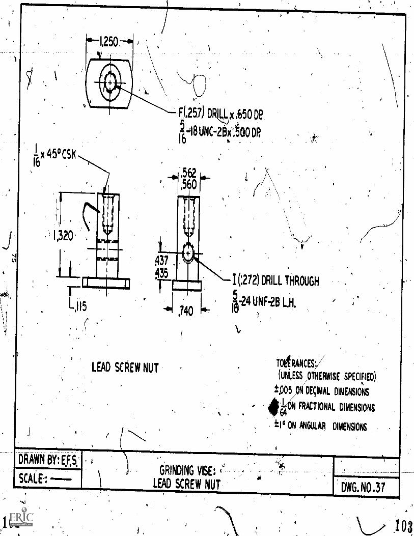
1250
I x 45° CSIt16
,
1,320
,I15
DRAWN BY: EF
SCALE,
437
435
LEAD SCAEW NUT
F(.257) DR4jx,650 DE'
.5 418 UNC-28x atao DR16
to-
,740
1(272) DRILL THROUGH
5w.24 UNF..28 LH.
TOARANCES'
(UNLESS /OTHERWISE SPECIFIED)
ipo5 pm DEcIMAL DIMENSIONS
,CON FRACTIONAL DIMENSIONS
III° ON ANGULAR DIMENSIONS
102
GRINDING VISE:
LEAD SCREW NUT. DWG. NO .31
a
a
.1 03,
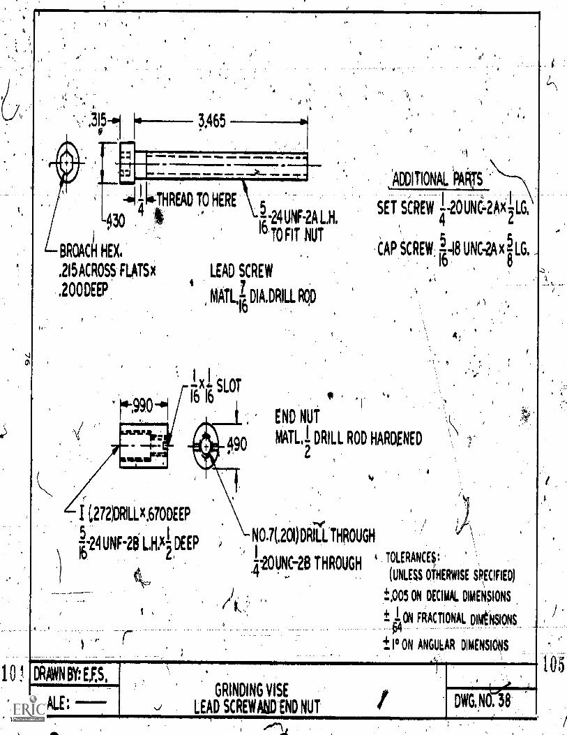
BROACH HEX,
.215 ACROSS FLAT9
.200DEEP
,ADDI'rIONAL oAks
-al [a-THREAD TO HERE ;SET SCREW 14-20UNt-2M LG.
030 1-24 UNRA HTO FIT NUT
LAP SCREW, smI8 UNC-2AXILG,
LEAD SCREW.%
4 7
MAIL 1'16
DIA.DRILL ROD
.1.
END NUT
po MATO DRILL ROD HARDENED2
I 2721DRILLx.670DEEP
5--24 UNF-28 x-
2DEEP
16
,
NO.7(.201)DRILL
,
THROUGH
.4--2OUN9-26 THROUGHTOLERANCq:
(UNLESS OTHERWISE OECIFIED)
'1%005 ON DECIMAL DIMENSIONS
± ION FRACTIONAL DIRtNSIONS
± I° ON ANGULAR DIMENSIONS
4.
DRAWN BY: EU,
SCALE:GRINDING VISE
LEAD SCREWAND END NUTDWG.NO. 3
,
105
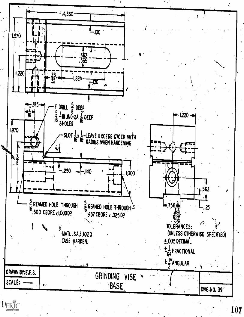
A,360
1220
1970
,4
I .ei
5
ris
1 r
.130
GS ND
rF DRILL DEEP,
/ §-,18UNk.A 1 DEEP1616
3HOLES
we Mt MI MI
I.
SLOT x ILEAVE EXCESS STOCK Kill16 16 RADIUS WHEN HARDENING
"El t. 250
NM WI. Ole
.140
rir
REAMED HOLE THROUGH16,500
CBORE x1,000De
RiAMED HOLE THROUGH
437 CBORE x .325 DP\MATL,S.A.E.1020
CASE VARDEN.
lijse ,I25
/)TOLERANCES:
(UNLESS OTHERWISE SPiCIFIED)
.±.005DECIMAaL
4'1 FRACTIONAL-64
rANGULAR2
DRAWN BY:E.F. S.
SCALE;GRINDING VISE
'BASE'DWG.NO. 39'
106107
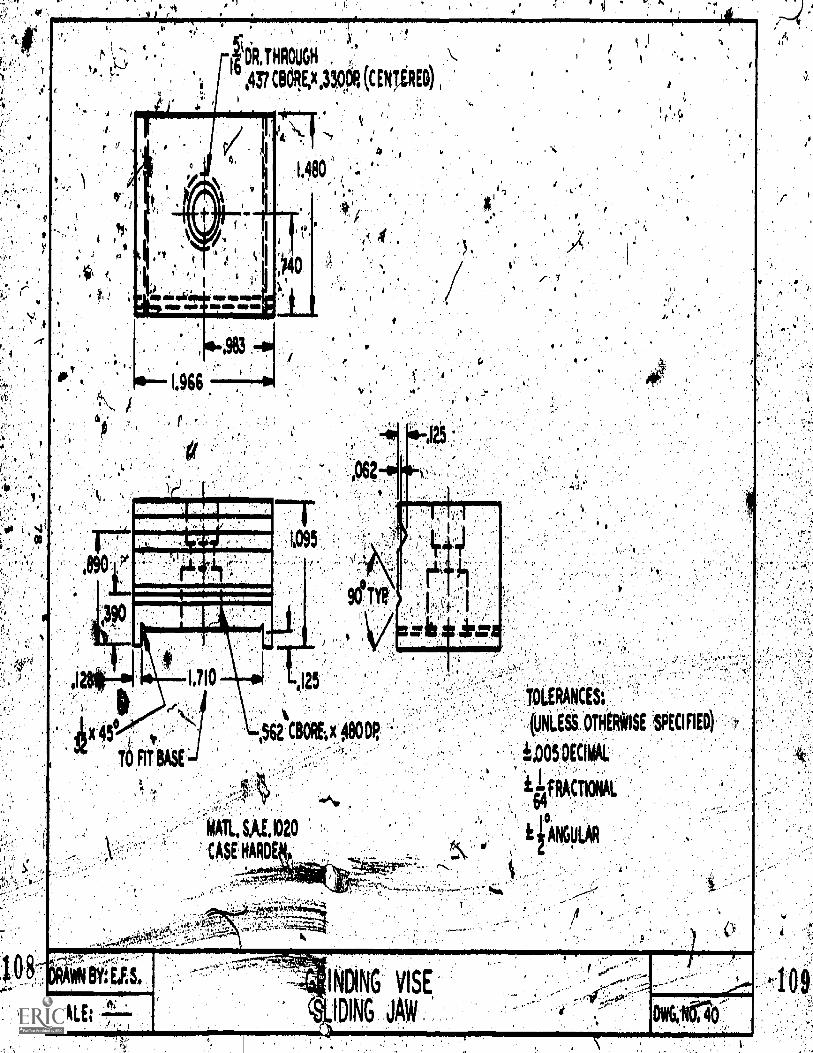
,.
1110 6125
TOLERANCES;
(UNLESS OTHERWISE SPECIFIED)
ii.005 DECIMAL
ilfRACTIONAL64
ifANGULAR
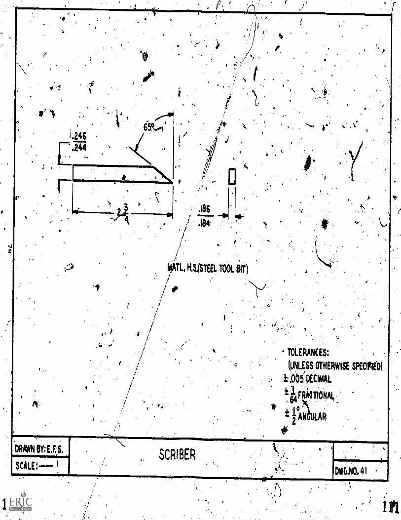
,ip
;
L244
DRAWN BY; U. S.
SCALE: \
4.
a.
L. HISI(STEEL TOOL elT)
'11
0
4
4 TOLERANCES.
(UMIESS OTHERWISE SPECIPIED)
1..005 DECIMAL
k 1 FRACTIONAL?, 64
t1°A2
a
SCRIBERr..
DWGINO. 41
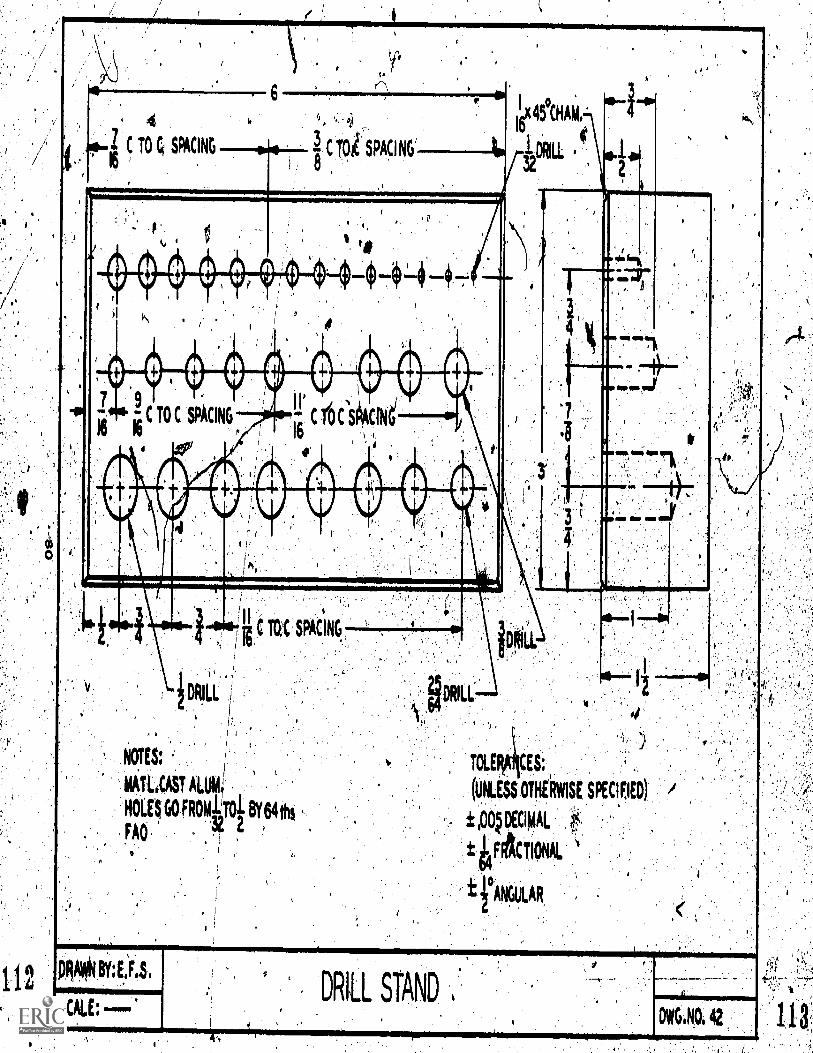
16x45°CHAM.
r321 61111
C TO C SPACING
DDRILL RILL
TOLE CES;
(UNLESS OTHERWISE SPECI,F.IED)
±,oqmpeAL
t e4FrActtoNAL
fANGULAR
I.
112PRAfitti BY:
SCALE;DRILL STAND
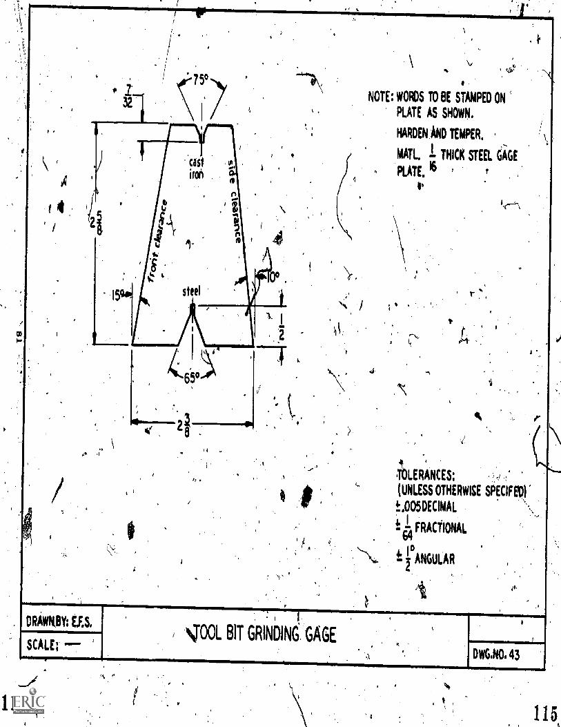
( 4
.1 ,
DRAWKBY: E.F.S.
SCALE; -
NOTE: WORDS TO BE STAMPED ON
PLATE AS SHOWN.
HARDEN AND TEMPER.
MAIL I THICK STEEL GAGE
PLATE. 16 r
4
I I
cm. BIT GRINDING GAGE
(N\,.
IDLERANCES:
(UNLESS OTHERWISE SPECIFEV
t.005DECIMAL
I FRACTIONAL64
ANGULAR
DWG.NO. 43
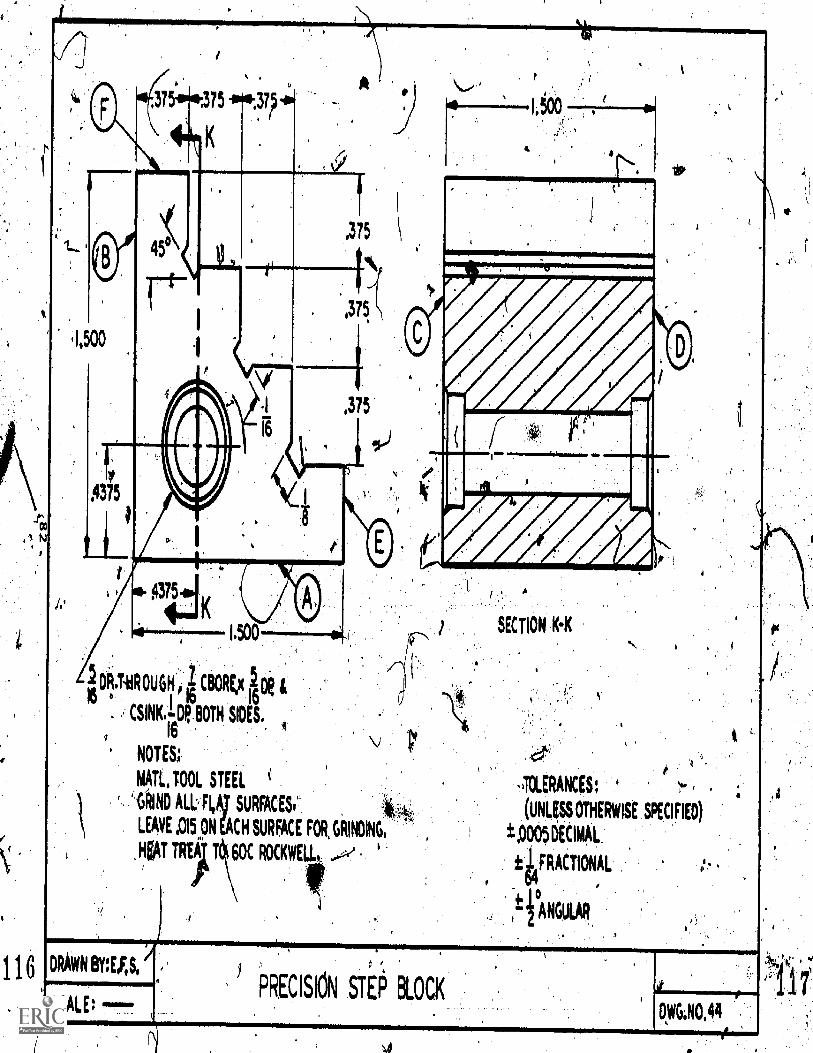
116
,
375 4i,37?-0
5
(1, 00
1'7°5
1
.375
,375
fis-
1.500
DR.T.HROUGH 1 CBORE,x 100 &16 e 1116 16
CSINK.-R.BOTH SIDES.16
NOTES;
MAIL. TOOL STEEi
AND ALL, FLA1 SURFACES'''.
LEAVE ,015 pm acm SURFACE FOR, GRIMING.
HEAT TIT 60C ROCKWE
c)0
"Area
SECTION KiK
4
,TCLERANCES:
(Lags OTHERWISE SKCIFIED)
p005 DECIMAL
ie4FRACTIONAL
tfANGULAR
I.
DRAWN BY:E.FIS,
SCALE: ---
,
PRECISION STE0 BLOCKDWG:NO.44
r,ct.
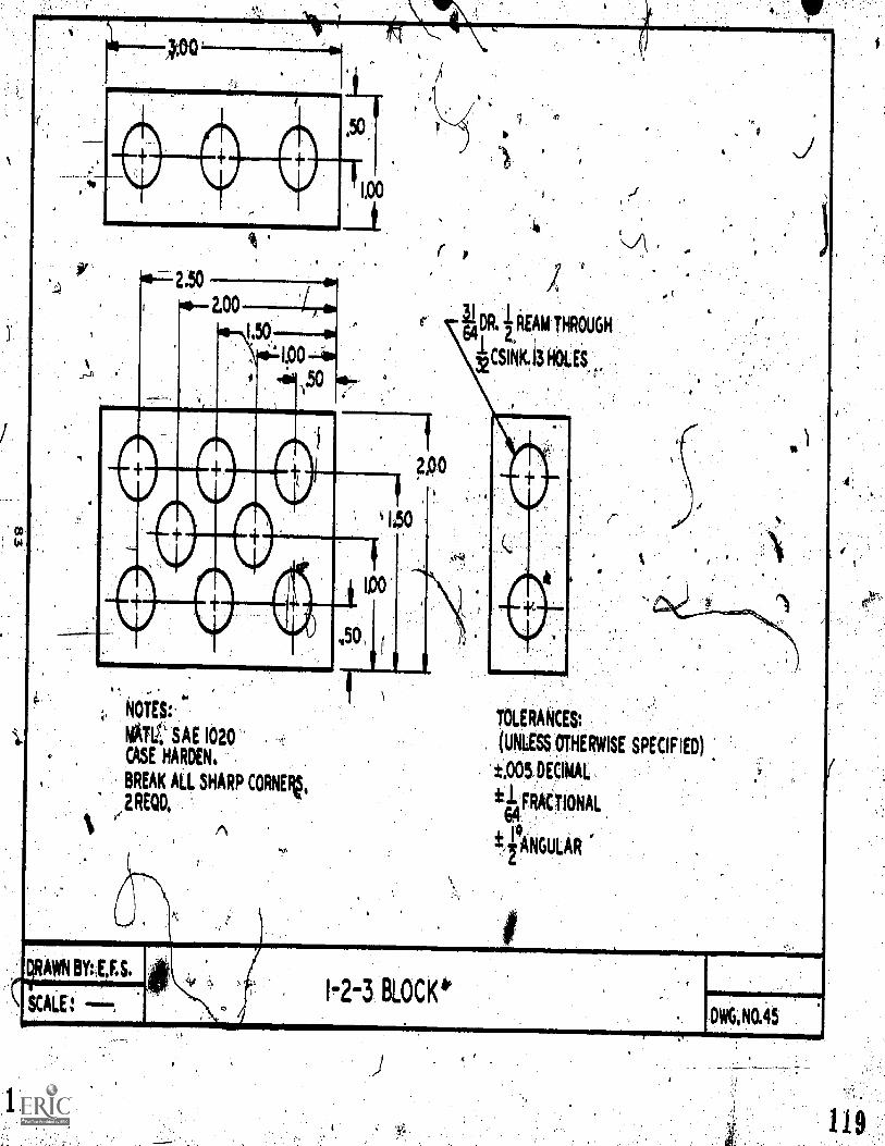
NOT6
MATV; SAE 1020
CASE HARDEN,
BREAK ALL SHARP CORNEF1,
,2REOD,
TOLERANCES:
(UNLESS OTHERWISE SPECIFIED)
t.005,DEdMAL
*I FRACTIONAL64
kfANGULAR
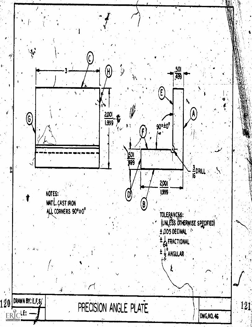
TOLE NCrE§:
(UN( $ 6THERWISE SVFIED)
405 DECIMAL
14 FRACTIONAL
± POLAR
120
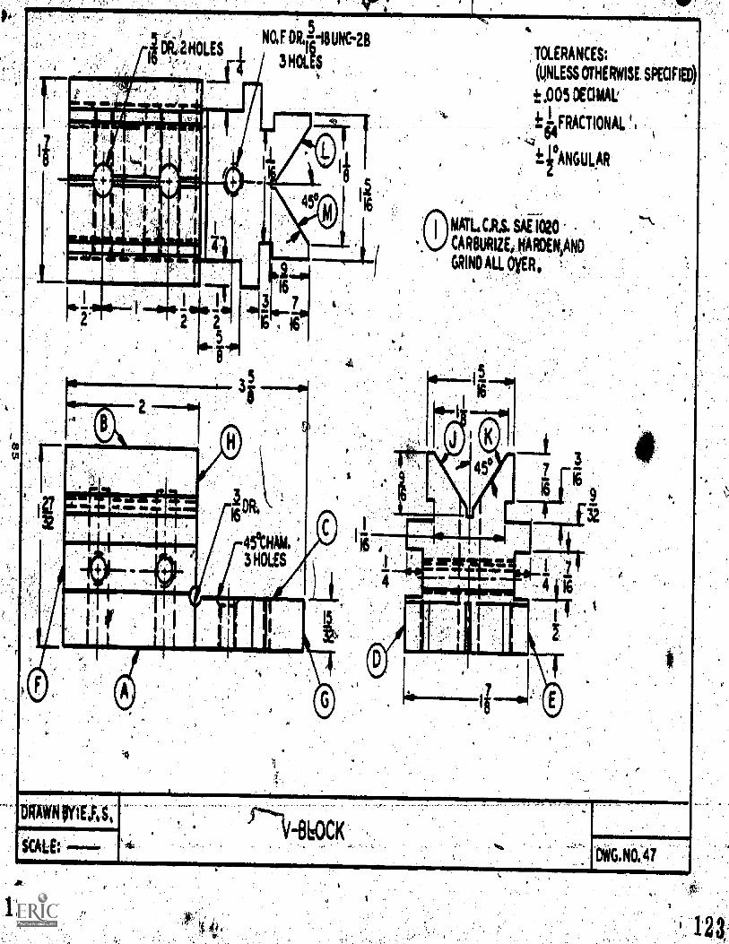
kr
TOLERANCES;
(UNLESS OMERNISE SPECIFIED)
t ,005 DECIMAL'
1 FRACTIONAL ti
..L4 tz
Si
fir ANGULAR
NM 11 IF 11111111 EMU MI 1
8600(=>
OWG,NO:41
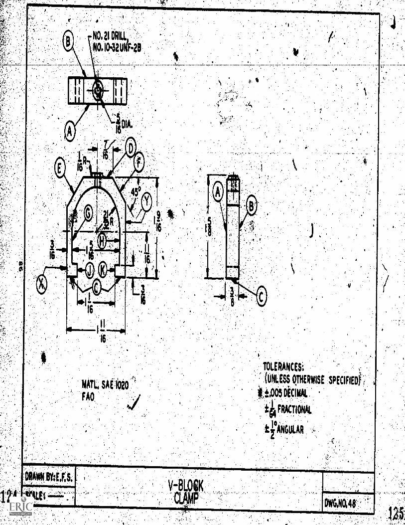
TOLERANCES:
(RISS 0,THERWISE SPECIFIED
tt.,005 DECIMAL
FRg!IONAL
t fANGULAR
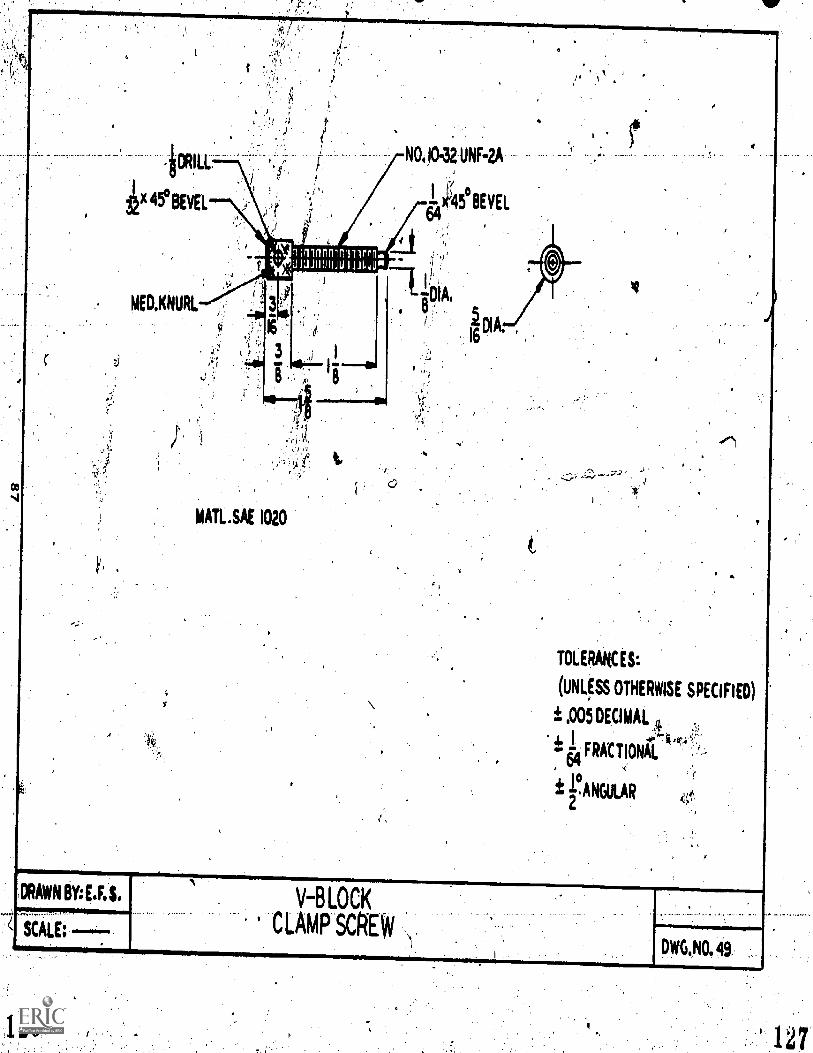
Ft
NO 9,32 UNNA
1 45°BEVEL64
wrirInfrnuirr.n.inJiU"
MATL.SAE 1020
'
TOLERANCES:
(UNLfSS OTHERWISE SPECIFIED)
± .005 DECIMAL g
FRACTIONC.M
rANGULAR2
DRAWN BY:E.F.$
SCALE:
V-BLOCK
.CLAMPSCREW,1
DWG.NO. 49.
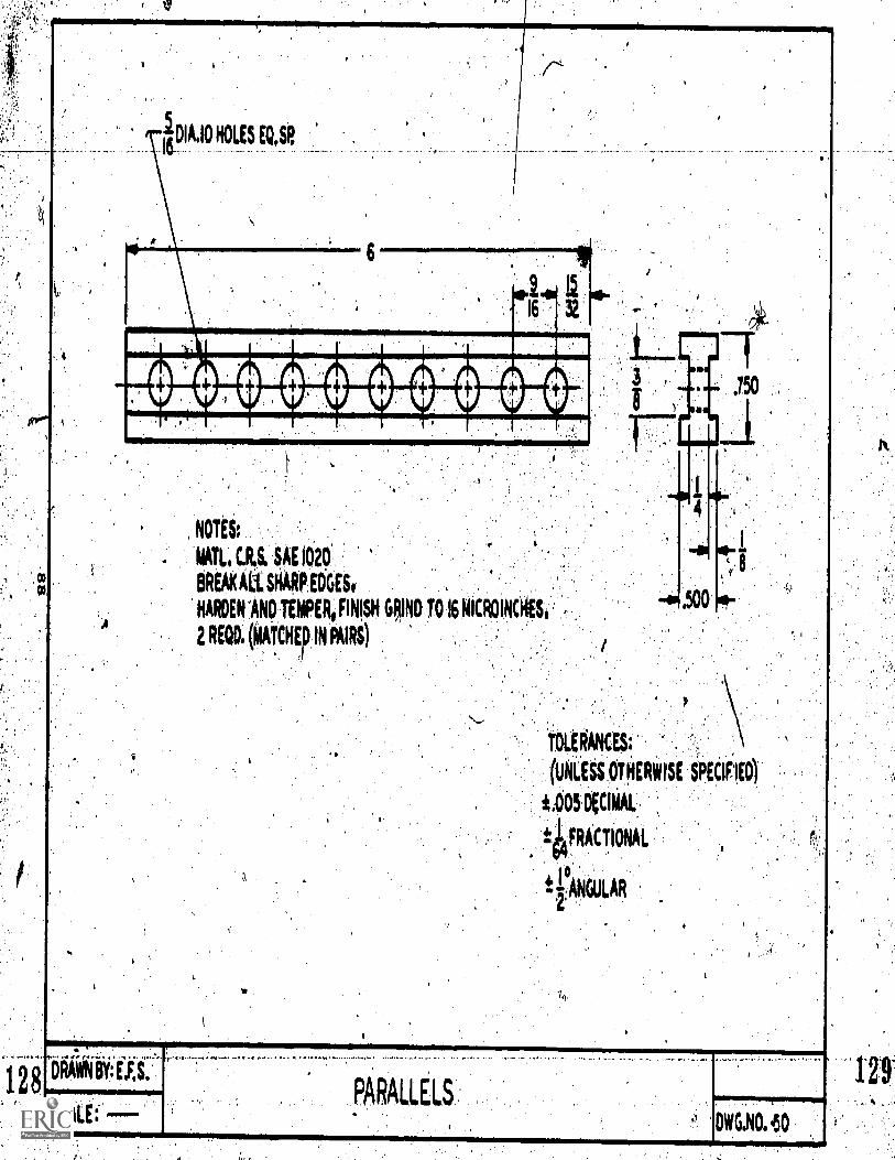
NOTES:
'ATLI C.R.S. SAE 1020
BREAK ALL SHARP EUGES,
HARDEN SAND TEMPER, FINISH GRIND TO 16 MICINCKES, ,
2 REOD. (MATCHEp IN PAIRS)
-4 mrI rwr.t AA ..P.1
ORIWN BY: tki..101011.ommerormpr
SCALE: -
iDLERANCES:
(UN-LESS OTHERWISE SPECIFIED
i.005 DClMAL
4FRACTIONAL
rANGULAR2.
DADAIIC1.
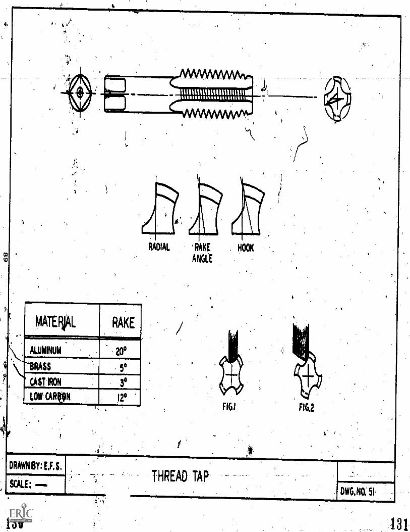
0, 41.
ENAAAAAAAAAA
minnutimunnum
MATENAL1...7..i.....ALUMINUM
RAKE
. 20°
L'BRASS
CAST IRON
LOW CARVN I °a
DRAWN BY: U.S.
SCALE:
RADIAL RAKE , HOOK
ANGLE
FIG,I
THREAD TAP
4
DWG.NO. 5I
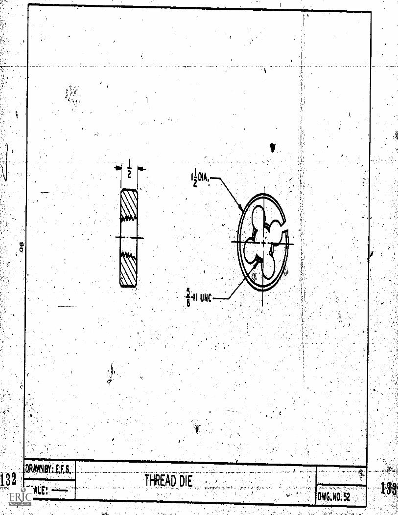
13.
(Alt ----THRAD DIE
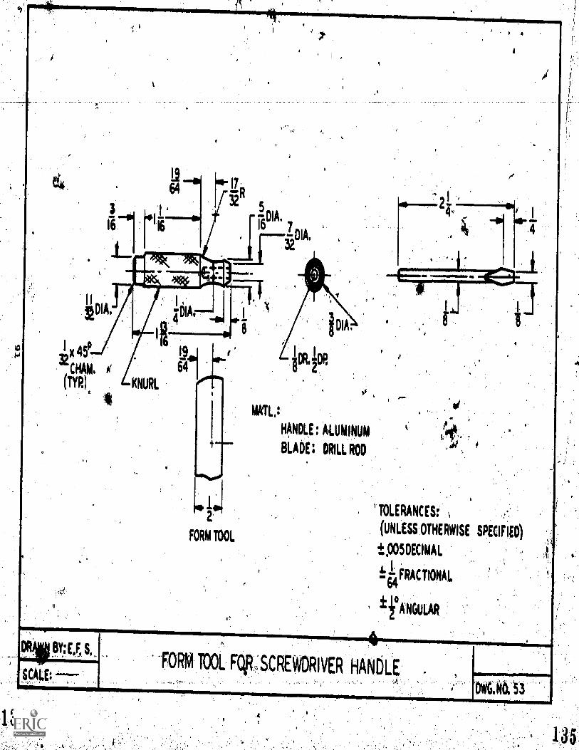
TOLERANCES:
(UNLESS OTHERWISE SPECIFIED)
±.005DECIMAL
461 FRACTIONAL"64
ifANGULAR
vp-RIO BY:E'F' 5,-, FORM TOOL Felp _SCREWDRIVER HANDLE
OW6.NO, 53
SCALE:
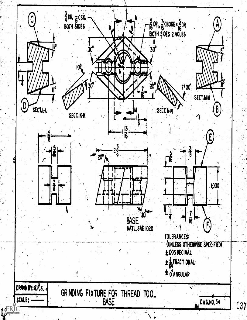
0/6HO
SECUL
3 1
I DR, g CSK
BOTH SIDES
SECT, KA
-
v5"411EHrAttclrkk.,
11'407
I ICBORE xiDp
BOTH IDES 2 HOLES
3e
#0120°
13
BASE
MATUAE 1020
'SKIM
16
7°30'
SECT.IN
1
1000
TOLERANCESt
OTHERVICKCIRU
±D05 DECIMAL
tWRAC TIONAL
ANGULAR
DRAWNBY:1,
E:
GRINDING FIXTURE (OR THREAD 1001.
BASE
M I II M. =I II 11111111WI 111111
DWG,NO, 54
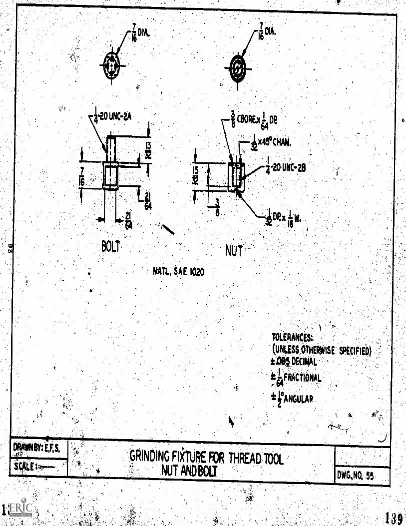
TOi:ERAkE4t;
(UNLESS,01E1r#11SE SPEtIfip
1$0.(tilkktFliktI001.
ii°ANGULAR
ra8139


![AUCTION SALE...*[19] JONES & SHIPMAN 1310 SURFACE GRINDER SERIAL NO. 3116N *[20] JONES & SHIPMAN 540 SURFACE GRINDER SERIAL NO.11F321-6 *[21] JONES & SHIPMAN 540 SURFACE GRINDER …](https://img.dokumen.tips/doc/110x75/606ed869aa2ee92e175f7db3/auction-19-jones-shipman-1310-surface-grinder-serial-no-3116n-20.jpg)