Embed Size (px)
Citation preview
page 1page 1
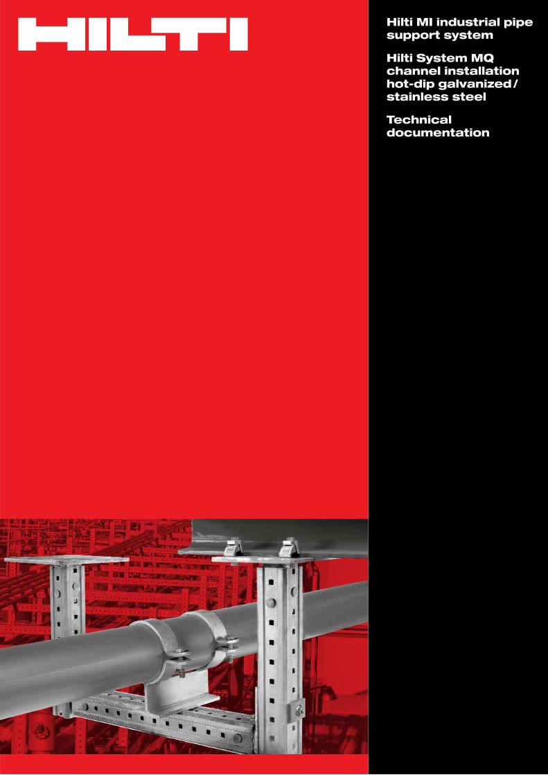
Hilti MI industrial pipe support system
Hilti System MQ channel installationhot-dip galvanized/stainless steel
Technical documentation
Hilti MI industrial pipe support system
page 2
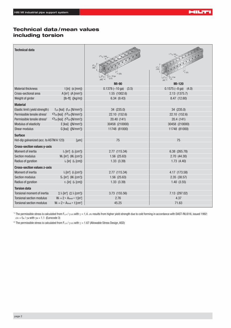
Technical data
MI-90 MI-120Material thickness t [in] (s [mm]) 0.1378 (~10 ga) (3.5) 0.1575 (~8 ga) (4.0)Cross-sectional area A [in2] (A [mm2]) 1.55 (1002.6) 2.13 (1375.7)Weight of girder [lb-ft] ([kg/m]) 6.34 (9.43) 8.47 (12.60)
MaterialElastic limit (yield strength) fy,k [ksi] (f y,k [N/mm2]) 34 (235.0) 34 (235.0)Permissible tensile stress1 σZul [ksi] (σZul [N/mm2]) 22.10 (152.6) 22.10 (152.6)Permissible tensile stress2 σZul [ksi] (σZul [N/mm2]) 20.40 (141) 20.4 (141)Modulus of elasticity E [ksi] ([N/mm2]) 30458 (210000) 30458 (210000)Shear modulus G [ksi] ([N/mm2]) 11748 (81000) 11748 (81000)
SurfaceHot-dip galvanized (acc. to ASTM A 123) [µm] 75 75
Cross-section values y-axisMoment of inertia ly [in4] (ly [cm4]) 2.77 (115.34) 6.38 (265.78)Section modulus Wy [in3] (Wy [cm3]) 1.56 (25.63) 2.70 (44.30)Radius of gyration iy [in] (iy [cm]) 1.33 (3.39) 1.73 (4.40)
Cross-section values z-axisMoment of inertia lz [in4] (lz [cm4]) 2.77 (115.34) 4.17 (173.58)Section modulus Sz [in3] (Wz [cm3]) 1.56 (25.63) 2.35 (38.57)Radius of gyration rz [in] (iz [cm]) 1.33 (3.39) 1.40 (3.55)
Torsion dataTorsional moment of inertia Σ lt [in4] (Σ lt [cm4]) 3.73 (155.56) 7.13 (297.02)Torsional section modulus Wt = 2 * ABredt * t [in3] 2.76 4.37Torsional section modulus Wt = 2 * ABredt * t [cm3] 45.25 71.63
Technical data /mean valuesincluding torsion
39/16" (90)
115/16" (50)
1" (25)39/16" s = 10 ga
(3.5)(90)
4 3/4"(120)
1 15/16" (50)
1" (25)
s = 8 ga(4)
3 9/16"
(90)
1) The permissible stress is calculated from Fy,k / γ G/Q with γ = 1,4. σD results from higher yield strength due to cold forming in accordance with DAST-RILI016, issued 1992:σD = fyk / γM with γM = 1.1 (Eurocode 3)
2) The permissible stress is calculated from Fy,k / γ G/Q with γ = 1.67 (Allowable Stress Design, ASD)
Hilti MI industrial pipe support system
page 3
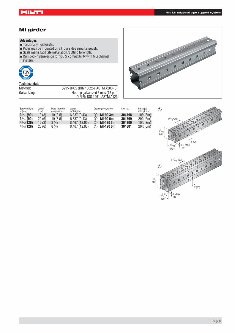
MI girder
Advantages■ Torsionally rigid girder.■ Pipes may be mounted on all four sides simultaneously.■ Scale marks facilitate installation /cutting to length.■ Crimped-in depression for 100% compatibility with MQ channel
system.
Section height Length Metal thickness Weight Ordering designation Item no. Packagedin [mm] ft (m) gauge (mm) lb/ft (kg/m) in lengths of
3 9⁄16 (90) 10 (3) 10 (3.5) 6.337 (9.43) �➊MI-90 3m 304798 10ft (3m)3 9⁄16 (90) 20 (6) 10 (3.5) 6.337 (9.43) �➀MI-90 6m 304799 20ft (6m)4 3⁄4 (120) 10 (3) 8 (4) 8.467 (12.60) �➊MI-120 3m 304800 10ft (3m)4 3⁄4 (120) 20 (6) 8 (4) 8.467 (12.60) �➁MI-120 6m 304801 20ft (6m)
Technical dataMaterial: S235 JRG2 (DIN 10025), ASTM A283 (C) Galvanizing: Hot-dip galvanized 3 mils (75 µm)
DIN EN ISO 1461, ASTM A123
39/16" (90)
115/16" (50)
1" (25)39/16" s = 10 ga
(3.5)(90)
�
4 3/4"120)
1 15/16" (50)
1" (25)
s = 8 ga(4)
3 9/16"
(90)
�
Hilti MI industrial pipe support system
page 4
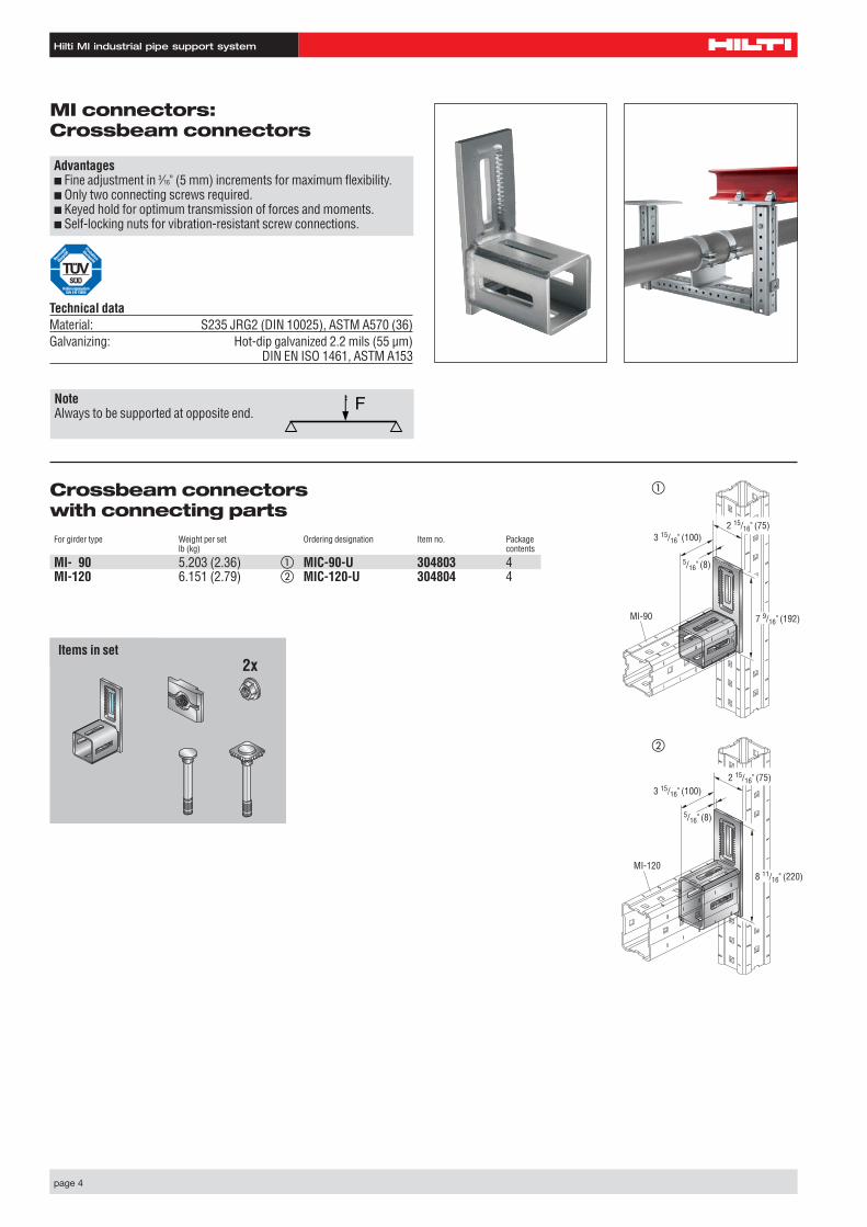
MI connectors: Crossbeam connectors
Advantages■ Fine adjustment in 3⁄16" (5 mm) increments for maximum flexibility.■ Only two connecting screws required.■ Keyed hold for optimum transmission of forces and moments.■ Self-locking nuts for vibration-resistant screw connections.
Technical dataMaterial: S235 JRG2 (DIN 10025), ASTM A570 (36) Galvanizing: Hot-dip galvanized 2.2 mils (55 µm)
DIN EN ISO 1461, ASTM A153
Crossbeam connectors with connecting partsFor girder type Weight per set Ordering designation Item no. Package
lb (kg) contents
MI- 90 5.203 (2.36) � MIC-90-U 304803 4MI-120 6.151 (2.79) � MIC-120-U 304804 4
Set besteht aus:2x
NoteAlways to be supported at opposite end.
7 9/16" (192)
2 15/16" (75)
5/16" (8)
3 15/16" (100)
MI-90
MI-120
5/16" (8)
3 15/16" (100)
8 11/16" (220)
2 15/16" (75)
�
�
Items in set
Hilti MI industrial pipe support system
page 5
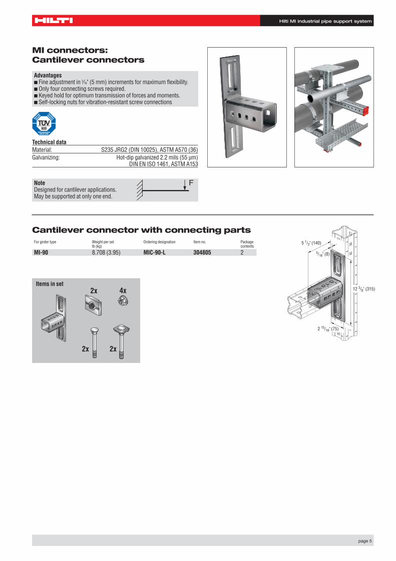
MI connectors: Cantilever connectors
Advantages■ Fine adjustment in 3⁄16" (5 mm) increments for maximum flexibility.■ Only four connecting screws required.■ Keyed hold for optimum transmission of forces and moments.■ Self-locking nuts for vibration-resistant screw connections
Technical dataMaterial: S235 JRG2 (DIN 10025), ASTM A570 (36) Galvanizing: Hot-dip galvanized 2.2 mils (55 µm)
DIN EN ISO 1461, ASTM A153
Set besteht aus:4x
2x 2x
2x 12 3/8" (315)
2 15/16" (75)
5 1/2" (140)
5/16" (8)
Cantilever connector with connecting partsFor girder type Weight per set Ordering designation Item no. Package
lb (kg) contents
MI-90 8.708 (3.95) MIC-90-L 304805 2➀
NoteDesigned for cantilever applications.May be supported at only one end.
Items in set
Hilti MI industrial pipe support system
page 6
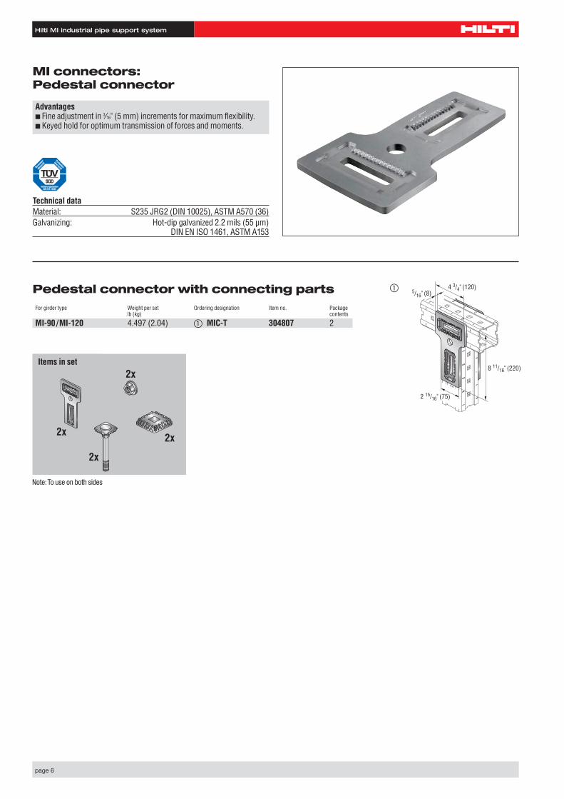
MI connectors: Pedestal connector
Technical dataMaterial: S235 JRG2 (DIN 10025), ASTM A570 (36) Galvanizing: Hot-dip galvanized 2.2 mils (55 µm)
DIN EN ISO 1461, ASTM A153
8 11/16" (220)
5/16" (8)4 3/4" (120)
2 15/16" (75)
Pedestal connector with connecting partsFor girder type Weight per set Ordering designation Item no. Package
lb (kg) contents
MI-90/MI-120 4.497 (2.04) � MIC-T 304807 2
Advantages■ Fine adjustment in 3⁄16" (5 mm) increments for maximum flexibility.■ Keyed hold for optimum transmission of forces and moments.
�
Set besteht aus:2x
2x
2x2x
Items in set
Note:To use on both sides
Hilti MI industrial pipe support system
page 7
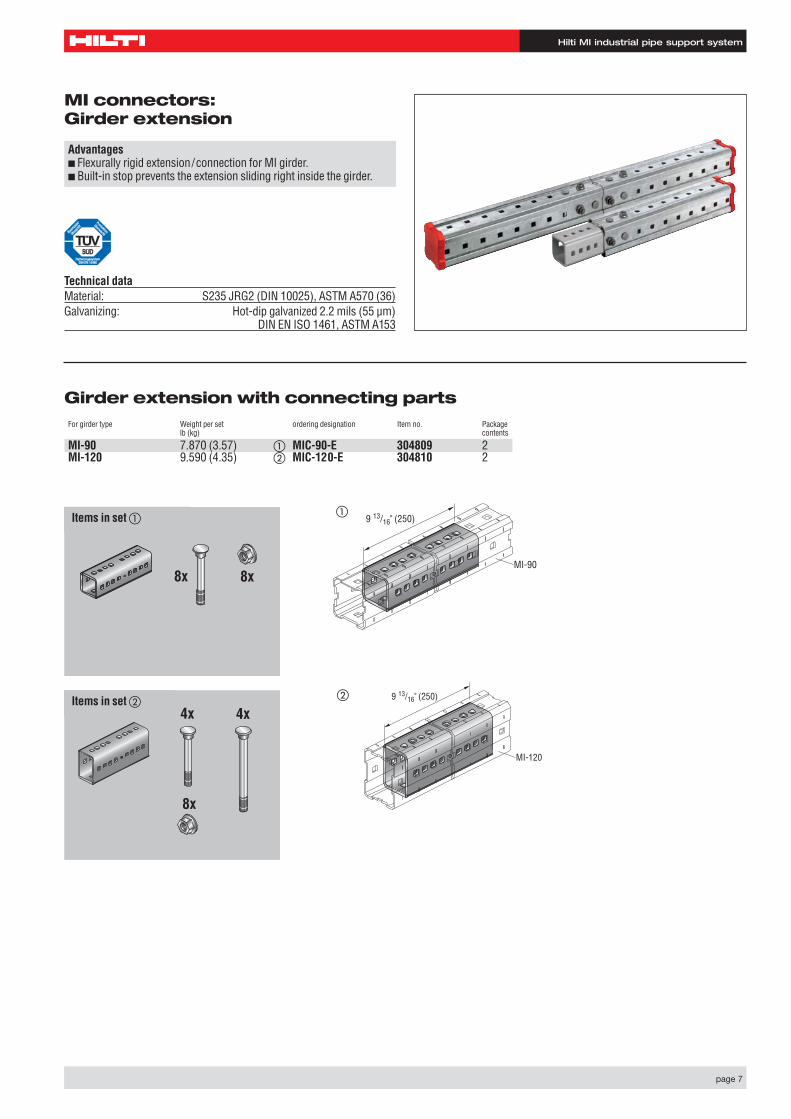
MI connectors: Girder extension
Advantages■ Flexurally rigid extension/connection for MI girder.■ Built-in stop prevents the extension sliding right inside the girder.
Technical dataMaterial: S235 JRG2 (DIN 10025), ASTM A570 (36) Galvanizing: Hot-dip galvanized 2.2 mils (55 µm)
DIN EN ISO 1461, ASTM A153
Set besteht aus �:
8x8x
9 13/16" (250)
MI-90
Girder extension with connecting partsFor girder type Weight per set ordering designation Item no. Package
lb (kg) contents
MI-90 7.870 (3.57) � MIC-90-E 304809 2MI-120 9.590 (4.35) � MIC-120-E 304810 2
Set besteht aus �:
8x
4x 4x
MI-120
9 13/16" (250)
�
�
Items in set �
Items in set �
Hilti MI industrial pipe support system
page 8
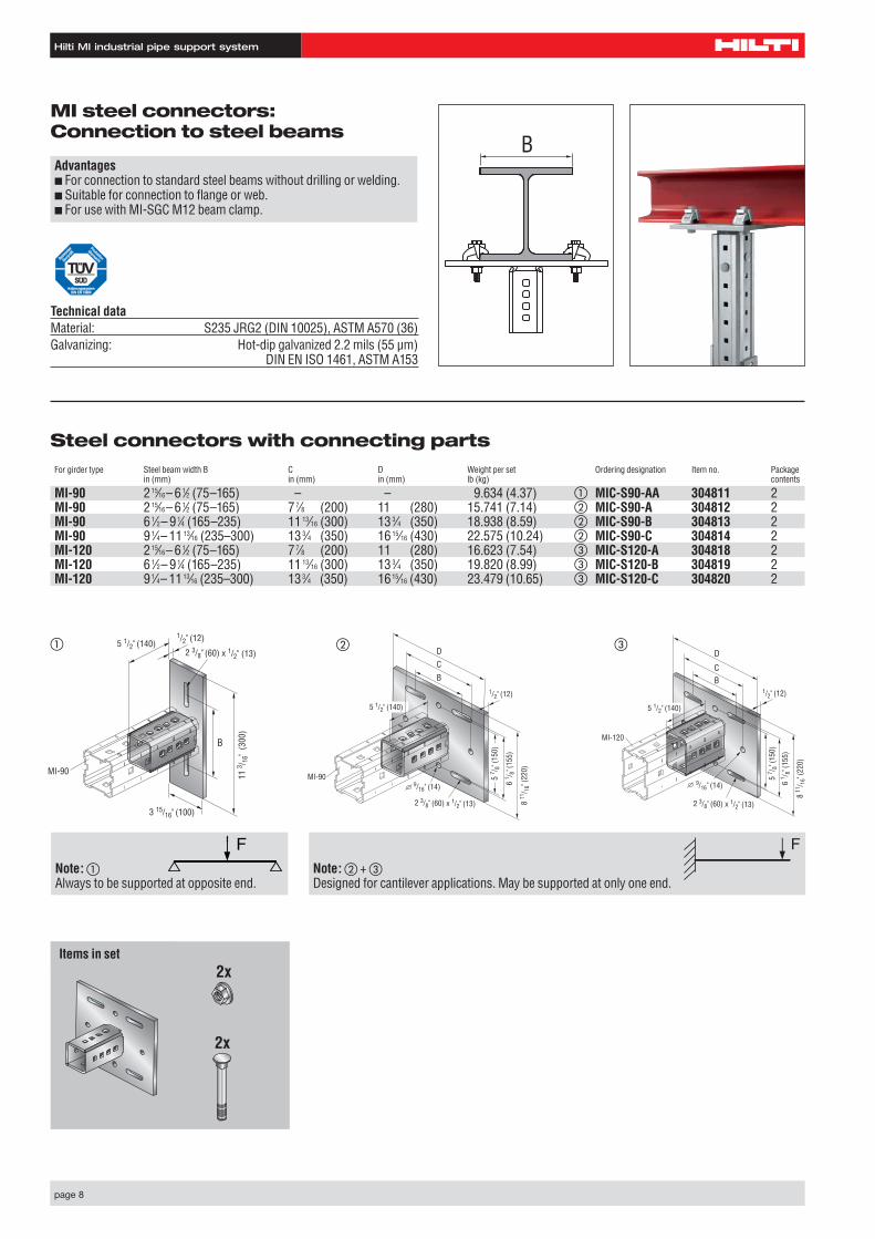
Steel connectors with connecting partsFor girder type Steel beam width B C D Weight per set Ordering designation Item no. Package
in (mm) in (mm) in (mm) lb (kg) contents
MI-90 215⁄16– 61⁄2 (75–165) – – 9.634 (4.37) � MIC-S90-AA 304811 2MI-90 215⁄16– 61⁄2 (75–165) 77⁄8 (200) 11 (280) 15.741 (7.14) � MIC-S90-A 304812 2MI-90 61⁄2– 91⁄4 (165–235) 1113⁄16 (300) 133⁄4 (350) 18.938 (8.59) � MIC-S90-B 304813 2MI-90 91⁄4– 1113⁄16 (235–300) 133⁄4 (350) 1615⁄16 (430) 22.575 (10.24) � MIC-S90-C 304814 2MI-120 215⁄16– 61⁄2 (75–165) 77⁄8 (200) 11 (280) 16.623 (7.54) � MIC-S120-A 304818 2MI-120 61⁄2– 91⁄4 (165–235) 1113⁄16 (300) 133⁄4 (350) 19.820 (8.99) � MIC-S120-B 304819 2MI-120 91⁄4– 1113⁄16 (235–300) 133⁄4 (350) 1615⁄16 (430) 23.479 (10.65) � MIC-S120-C 304820 2
MI steel connectors: Connection to steel beams
Advantages■ For connection to standard steel beams without drilling or welding.■ Suitable for connection to flange or web.■ For use with MI-SGC M12 beam clamp.
Technical dataMaterial: S235 JRG2 (DIN 10025), ASTM A570 (36) Galvanizing: Hot-dip galvanized 2.2 mils (55 µm)
DIN EN ISO 1461, ASTM A153
B
2 3/8" (60) x 1/2" (13)
MI-90
1/2" (12)
B
CD
5 1/2" (140)
9/16" (14)
8 11
/ 16"
(220
)
5 7 / 8
" (15
0)
6 1 / 8
" (15
5)
BC
D
MI-120
2 3/8" (60) x 1/2" (13)
1/2" (12)
5 1/2" (140)
9/16" (14)
8 11
/ 16"
(220
)
5 7 / 8
" (15
0)
6 1 / 8
" (15
5)
�
Set besteht aus:2x
2x
B
MI-90
2 3/8" (60) x 1/2" (13)
1/2" (12)5 1/2" (140)
3 15/16" (100)
11 3 / 1
6" (
300)
��
Note: �Always to be supported at opposite end.
Note: � + �Designed for cantilever applications. May be supported at only one end.
Items in set
Hilti MI industrial pipe support system
page 9
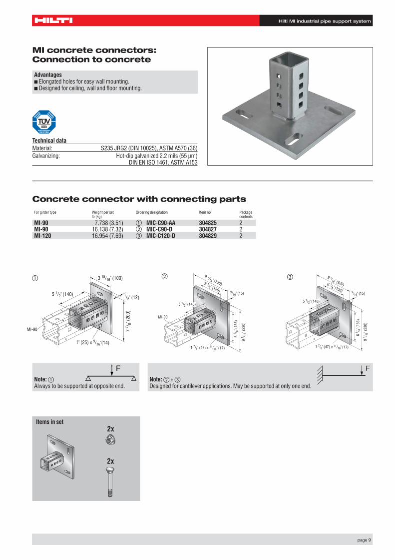
Concrete connector with connecting partsFor girder type Weight per set Ordering designation Item no Package
lb (kg) contents
MI-90 7.738 (3.51) � MIC-C90-AA 304825 2MI-90 16.138 (7.32) � MIC-C90-D 304827 2MI-120 16.954 (7.69) � MIC-C120-D 304829 2
MI concrete connectors: Connection to concrete
Advantages■ Elongated holes for easy wall mounting.■ Designed for ceiling, wall and floor mounting.
Technical dataMaterial: S235 JRG2 (DIN 10025), ASTM A570 (36) Galvanizing: Hot-dip galvanized 2.2 mils (55 µm)
DIN EN ISO 1461, ASTM A153
Set besteht aus:2x
2x
MI-90
1/2" (12)5 1/2" (140)
7 7 / 8
" (20
0)
3 15/16" (100)
1" (25) x 9/16"(14)
MI-90
9/16" (15)
9 1 / 1
6" (2
30)
5 1/2" (140)
9 1/16 " (230)
1 7/8" (47) x 11/16" (17)
6 1/8 " (156)
6 1 / 8
" (15
6)
9/16" (15)
9 1 / 1
6" (2
30)
5 1/2" (140)
9 1/16 " (230)
1 7/8" (47) x 11/16" (17)
6 1/8 " (156)
6 1 / 8
" (15
6)
� � �
Note: �Always to be supported at opposite end.
Note: � + �Designed for cantilever applications. May be supported at only one end.
Items in set
Hilti MI industrial pipe support system
page 10
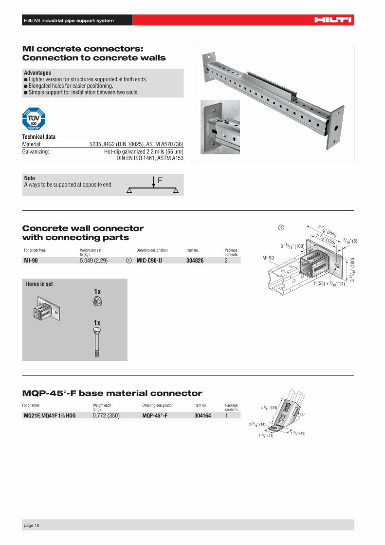
Concrete wall connector with connecting partsFor girder type Weight per set Ordering designation Item no. Package
lb (kg) contents
MI-90 5.049 (2.29) � MIC-C90-U 304826 2
MI concrete connectors: Connection to concrete walls
Advantages■ Lighter version for structures supported at both ends.■ Elongated holes for easier positioning.■ Simple support for installation between two walls.
Technical dataMaterial: S235 JRG2 (DIN 10025), ASTM A570 (36) Galvanizing: Hot-dip galvanized 2.2 mils (55 µm)
DIN EN ISO 1461, ASTM A153
Set besteht aus:1x
1x
MI-90
1" (25) x 9/16"(14)
5/16" (8)
3 15
/ 16"
(100
)
3 15/16" (100)
7 7/8 " (200)5 7/8 " (150)
�
NoteAlways to be supported at opposite end.
Items in set
MQP-45°-F base material connectorFor channel Weight each Ordering designation Item no. Package
lb (g) contents
MQ21F, MQ41F 15⁄8 HDG 0.772 (350) MQP-45°-F 304164 1 45°
1 5/8" (42)
4 1/8" (105)
9/16" (14)
1 5/8" (41)
Hilti MI industrial pipe support system
page 11
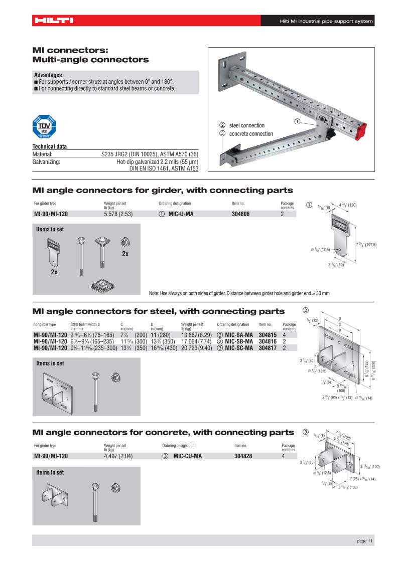
MI connectors: Multi-angle connectors
Advantages■ For supports / corner struts at angles between 0° and 180°.■ For connecting directly to standard steel beams or concrete.
Technical dataMaterial: S235 JRG2 (DIN 10025), ASTM A570 (36) Galvanizing: Hot-dip galvanized 2.2 mils (55 µm)
DIN EN ISO 1461, ASTM A153
MI angle connectors for girder, with connecting parts
For girder type Weight per set Ordering designation Item no. Packagelb (kg) contents
MI-90/MI-120 5.578 (2.53) � MIC-U-MA 304806 2
MI angle connectors for steel, with connecting parts
For girder type Steel beam width B C D Weight per set Ordering designation Item no. Packagein (mm) in (mm) in (mm) lb (kg) contents
MI-90/MI-120 215⁄16–61⁄2 (75–165) 77⁄8 (200) 11 (280) 13.867(6.29) � MIC-SA-MA 304815 4MI-90/MI-120 61⁄2–91⁄4 (165–235) 1113⁄16 (300) 133⁄4 (350) 17.064(7.74) � MIC-SB-MA 304816 2MI-90/MI-120 91⁄4–1113⁄16 (235–300) 133⁄4 (350) 1615⁄16 (430) 20.723(9.40) � MIC-SC-MA 304817 2
MI angle connectors for concrete, with connecting parts
For girder type Weight per set Ordering designation Item no. Packagelb (kg) contents
MI-90/MI-120 4.497 (2.04) � MIC-CU-MA 304828 4
1/2" (12,5)
3 1/8" (80)
7 3/4" (197,5)
4 3/4" (120)5/16" (8)
Set besteht aus:
2x
2x
Set besteht aus:
Set besteht aus:
B
C
D
2 3/8" (60) x 1/2" (13)
1/2" (12,5)
1/4" (6)
9/16" (14)
8 11
/ 16"
(220
)3 1/8" (80)
1/2" (12)
3 15/16" (100)
6 1 / 8
" (15
5)
�
�
1" (25) x 9/16" (14)
5/16" (8)
3 15/16" (100)
3 15/16" (100)
1/4" (6)
7 7/8 " (200)
1/2" (12,5)
3 1/8" (80)
5 7/8 " (150)
�
Items in set
Items in set
Items in set
�
�
� steel connectionconcrete connection
Note: Use always on both sides of girder. Distance between girder hole and girder end ≥ 30 mm
Hilti MI industrial pipe support system
page 12
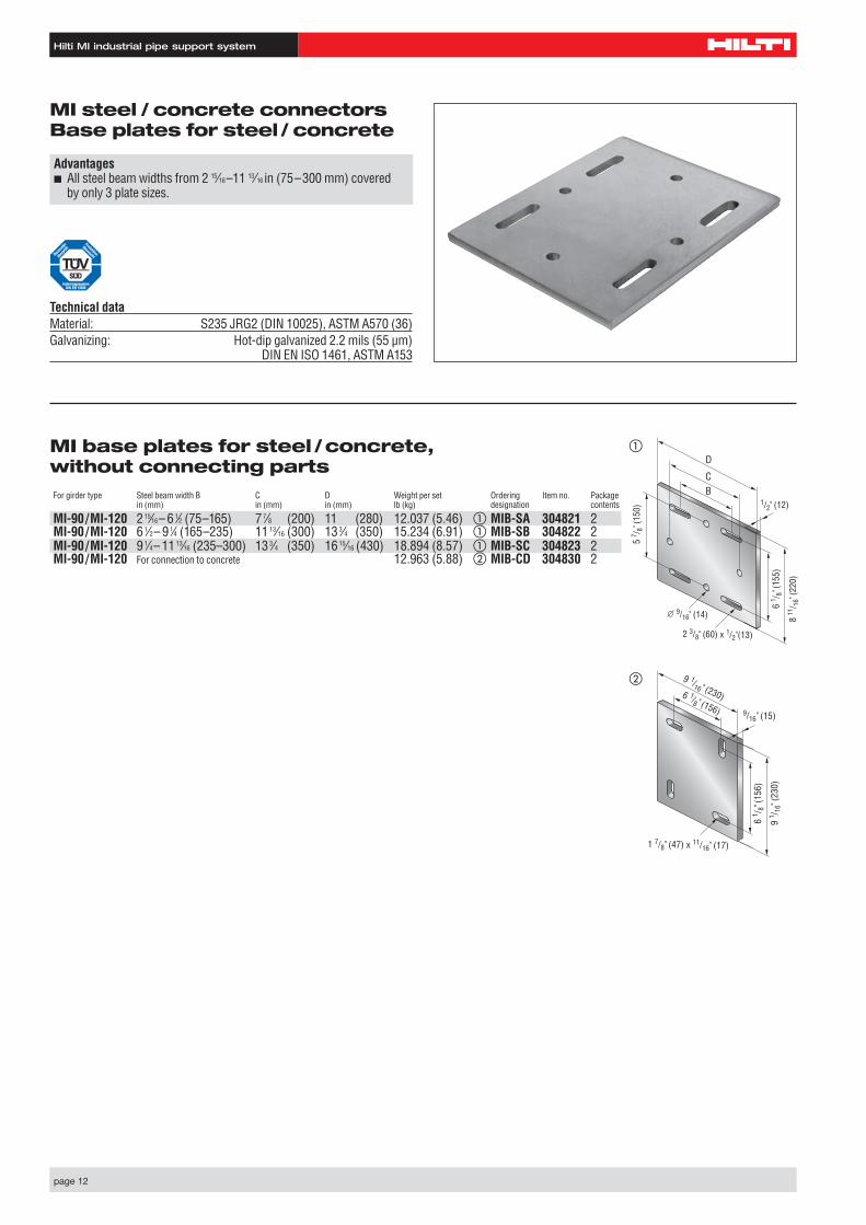
MI steel / concrete connectorsBase plates for steel / concrete
Advantages■ All steel beam widths from 2 15⁄16–11 13⁄16 in (75–300 mm) covered
by only 3 plate sizes.
Technical dataMaterial: S235 JRG2 (DIN 10025), ASTM A570 (36) Galvanizing: Hot-dip galvanized 2.2 mils (55 µm)
DIN EN ISO 1461, ASTM A153
�
BC
D
2 3/8" (60) x 1/2"(13)
1/2" (12)
9/16" (14) 8 11
/ 16"
(220
)
5 7 / 8
" (15
0)
6 1 / 8
" (15
5)
1 7/8" (47) x 11/16" (17)
9 1/16 " (230)6 1/8 " (156) 9/16" (15)
9 1 / 1
6" (2
30)
6 1 / 8
" (15
6)
MI base plates for steel /concrete, without connecting partsFor girder type Steel beam width B C D Weight per set Ordering Item no. Package
in (mm) in (mm) in (mm) lb (kg) designation contents
MI-90/MI-120 215⁄16– 61⁄2 (75–165) 77⁄8 (200) 11 (280) 12.037 (5.46) � MIB-SA 304821 2MI-90/MI-120 61⁄2– 91⁄4 (165–235) 1113⁄16 (300) 133⁄4 (350) 15.234 (6.91) � MIB-SB 304822 2MI-90/MI-120 91⁄4– 1113⁄16 (235–300) 133⁄4 (350) 1615⁄16 (430) 18.894 (8.57) � MIB-SC 304823 2MI-90/MI-120 For connection to concrete 12.963 (5.88) � MIB-CD 304830 2
�
Hilti MI industrial pipe support system
page 13
MI basic connector for welding, without connecting parts
For girder type Weight per set Ordering designation Item no. Packagelb (kg) contents
MI- 90 3.175 (1.44) � MIC-SC90 304824 2MI-120 3.990 (1.81) � MIC-SC120 304808 2
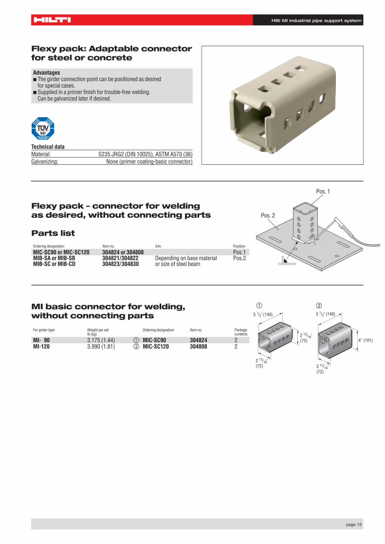
Flexy pack: Adaptable connectorfor steel or concrete
Advantages■ The girder connection point can be positioned as desired
for special cases.■ Supplied in a primer finish for trouble-free welding.
Can be galvanized later if desired.
Technical dataMaterial: S235 JRG2 (DIN 10025), ASTM A570 (36) Galvanizing: None (primer coating-basic connector)
5 1/2" (140)
2 13/16"(72)
2 13/16" (72)
5 1/2" (140)
4" (101)
2 13/16" (72)
� �
Flexy pack – connector for welding as desired, without connecting parts
Parts listOrdering designation Item no. Info Position
MIC-SC90 or MIC-SC120 304824 or 304808 Pos.1MIB-SA or MIB-SB 304821/304822 Depending on base material Pos.2MIB-SC or MIB-CD 304823/304830 or size of steel beam
Pos. 2
Pos. 1
Hilti MI industrial pipe support system
page 14
1 3/8" (35) x 1/2" (13)
7 " (177,5) x 1 / 2"
(13)
1 15/16" (49)
1 1/8" (28,5)
9/16" (15)15 3/4" (400)
3 3/4" (96)
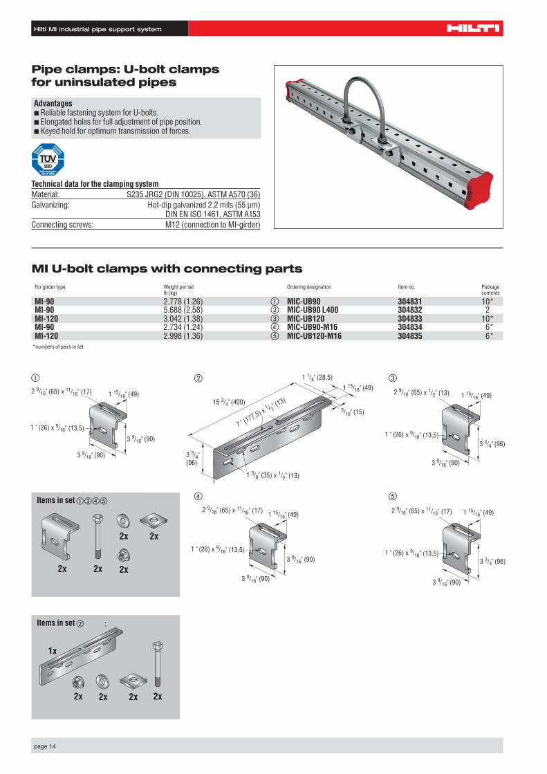
MI U-bolt clamps with connecting partsFor girder type Weight per set Ordering designation Item no. Package
lb (kg) contents
MI-90 2.778 (1.26) � MIC-UB90 304831 10*MI-90 5.688 (2.58) � MIC-UB90 L400 304832 2MI-120 3.042 (1.38) � MIC-UB120 304833 10*MI-90 2.734 (1.24) � MIC-UB90-M16 304834 6*MI-120 2.998 (1.36) � MIC-UB120-M16 304835 6*
*numbers of pairs in set
Advantages■ Reliable fastening system for U-bolts.■ Elongated holes for full adjustment of pipe position.■ Keyed hold for optimum transmission of forces.
Technical data for the clamping systemMaterial: S235 JRG2 (DIN 10025), ASTM A570 (36) Galvanizing: Hot-dip galvanized 2.2 mils (55 µm)
DIN EN ISO 1461, ASTM A153Connecting screws: M12 (connection to MI-girder)
2 9/16" (65) x 11/16" (17)
1 " (26) x 9/16" (13,5)
1 15/16" (49)
3 9/16" (90)
3 9/16" (90)
2 9/16" (65) x 1/2" (13)
1 " (26) x 9/16" (13,5)
1 15/16" (49)
3 9/16" (90)
3 3/4" (96)
2 9/16" (65) x 11/16" (17)
1 " (26) x 9/16" (13,5)
1 15/16" (49)
3 9/16" (90)
3 3/4" (96)
� �
�
�
Pipe clamps: U-bolt clamps for uninsulated pipes
Set : besteht aus:
2x
2x 2x
2x2x
Set : besteht aus:
2x
1x
2x 2x 2x
2 9/16" (65) x 11/16" (17)
1 " (26) x 9/16" (13,5)
1 15/16" (49)
3 9/16" (90)
3 9/16" (90)
�Items in set ����
Items in set �
Hilti MI industrial pipe support system
page 15
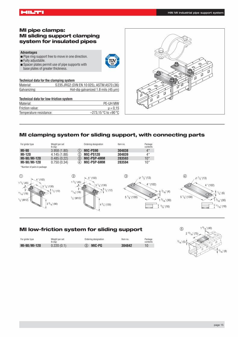
Advantages■ Pipe ring support free to move in one direction.■ Fully adjustable.■ Spacer plates permit use of pipe supports with
base plates of greater thickness.
Technical data for the clamping systemMaterial: S235 JRG2 (DIN EN 10 025), ASTM A570 (36)Galvanizing: Hot-dip galvanized 1.8 mils (45 µm)
5 1/8" (130)
4 " (102)
1/2" (12)11/16" (18)
1/2" (M12)3 9/16" (90)
1 3/4" (45)5 1/8" (130)
4 " (102)
1/2" (12)11/16" (18)
1/2" (M12)
4 3/4" (120)
1 3/4" (45)
� �
5 1/8" (130)
4 " (102)
1/2" (13)
5/8" (16)
3/16" (4)
1 3/16" (30)5 1/8" (130)
4 " (102)
1/2" (13)
11/16" (18)
1/4" (6)
1 3/16" (30)
� �
�
MI pipe clamps: MI sliding support clamping system for insulated pipes
For girder type Weight per set Ordering designation Item no. Packagelb (kg) contents
MI-90 3.958 (1.80) � MIC-PS90 304838 4*MI-120 4.145 (1.88) � MIC-PS120 304839 4*MI-90/MI-120 0.485 (0.22) � MIC-PSP-4MM 283593 10*MI-90/MI-120 0.750 (0.34) � MIC-PSP-6MM 283594 10**Number of pairs in package
For girder type Weight per set Ordering designation Item no. Packagelb (kg) contents
MI-90/MI-120 0.220 (0.1) � MIC-PG 304842 10
2 15/16" (75)
1 9/16" (40)
3/16" (5)
5/16" (8)
MI clamping system for sliding support, with connecting parts
MI low-friction system for sliding support
Technical data for low-friction systemMaterial: PE-UH MWFriction value: µ = 0,15Temperature resistance: –273,15 °C to +90 °C
Hilti MI industrial pipe support system
page 16
4 15/16" (126)
4 " (102)1/2" (M12)
6 1/8" (156)
4 " (102)1/2" (M12)
� �
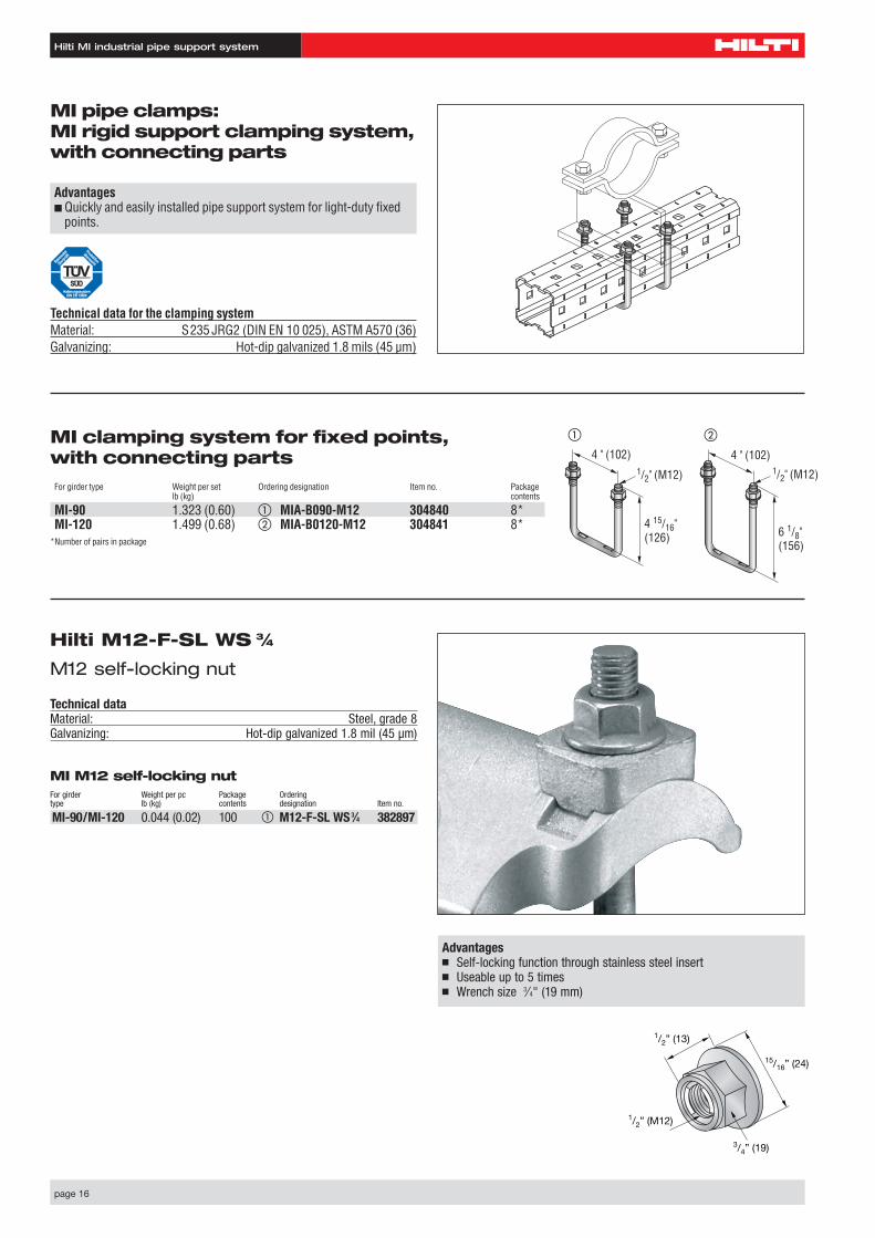
Advantages■ Quickly and easily installed pipe support system for light-duty fixed
points.
MI clamping system for fixed points, with connecting partsFor girder type Weight per set Ordering designation Item no. Package
lb (kg) contents
MI-90 1.323 (0.60) � MIA-B090-M12 304840 8*MI-120 1.499 (0.68) � MIA-B0120-M12 304841 8*
*Number of pairs in package
MI pipe clamps: MI rigid support clamping system,with connecting parts
Technical data for the clamping systemMaterial: S235 JRG2 (DIN EN 10 025), ASTM A570 (36)Galvanizing: Hot-dip galvanized 1.8 mils (45 µm)
Hilti M12-F-SL WS 3⁄4
M12 self-locking nut
Technical dataMaterial: Steel, grade 8Galvanizing: Hot-dip galvanized 1.8 mil (45 µm)
Advantages■ Self-locking function through stainless steel insert■ Useable up to 5 times■ Wrench size 3⁄4" (19 mm)
1/2” (M12)
3/4” (19)
15/16” (24)
1/2” (13)
MI M12 self-locking nutFor girder Weight per pc Package Orderingtype lb (kg) contents designation Item no.
MI-90/MI-120 0.044 (0.02) 100 � M12-F-SL WS3⁄4 382897
Hilti MI industrial pipe support system
page 17
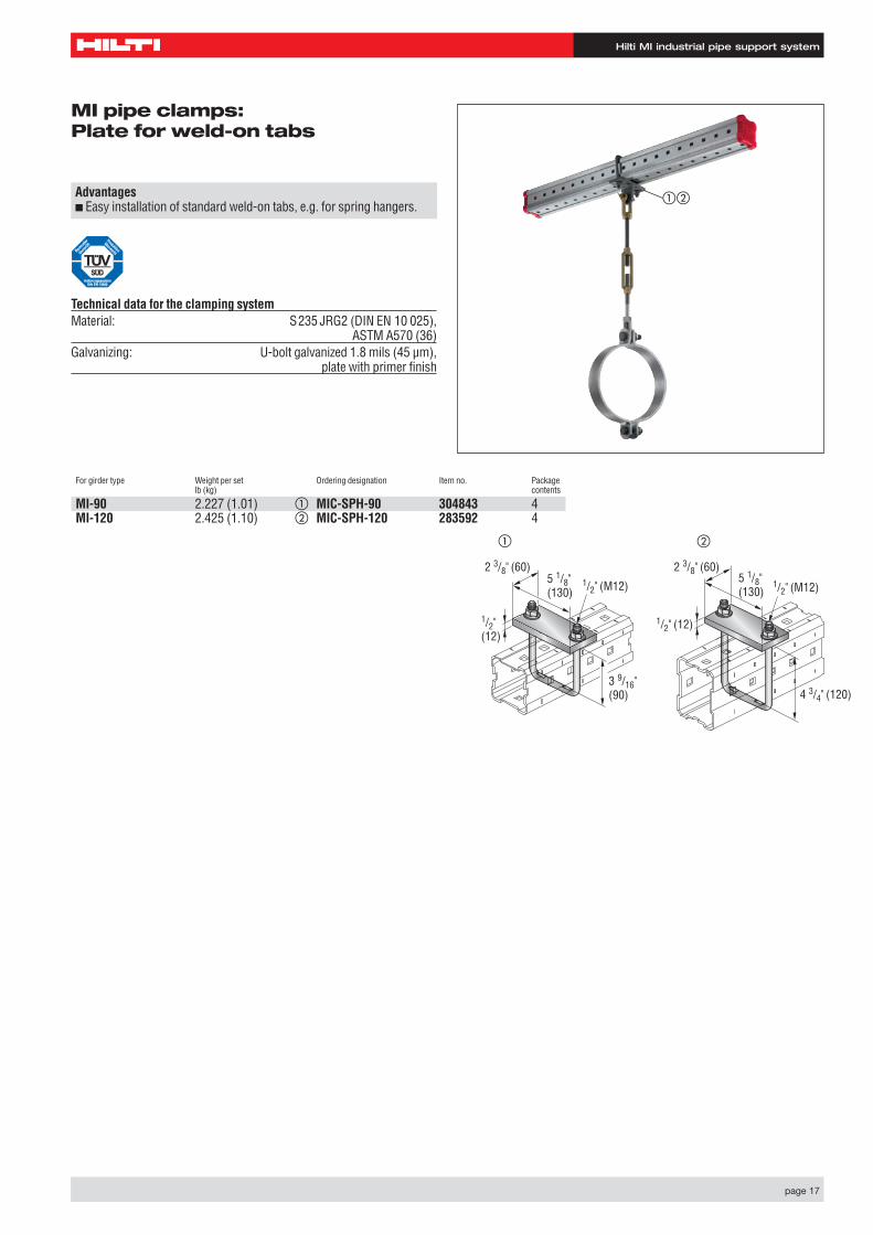
MI pipe clamps: Plate for weld-on tabs
Advantages■ Easy installation of standard weld-on tabs, e.g. for spring hangers.
Technical data for the clamping systemMaterial: S235 JRG2 (DIN EN 10 025),
ASTM A570 (36)Galvanizing: U-bolt galvanized 1.8 mils (45 µm),
plate with primer finish
For girder type Weight per set Ordering designation Item no. Packagelb (kg) contents
MI-90 2.227 (1.01) � MIC-SPH-90 304843 4MI-120 2.425 (1.10) � MIC-SPH-120 283592 4
1/2" (M12)
1/2"(12)
3 9/16" (90)
5 1/8" (130)
2 3/8" (60)
4 3/4" (120)
5 1/8"(130)
1/2" (M12)
1/2" (12)
2 3/8" (60)
� �
��
Hilti MI industrial pipe support system
page 18
For girder type Weight per set Ordering designation Item no. Packegelb (kg) contents
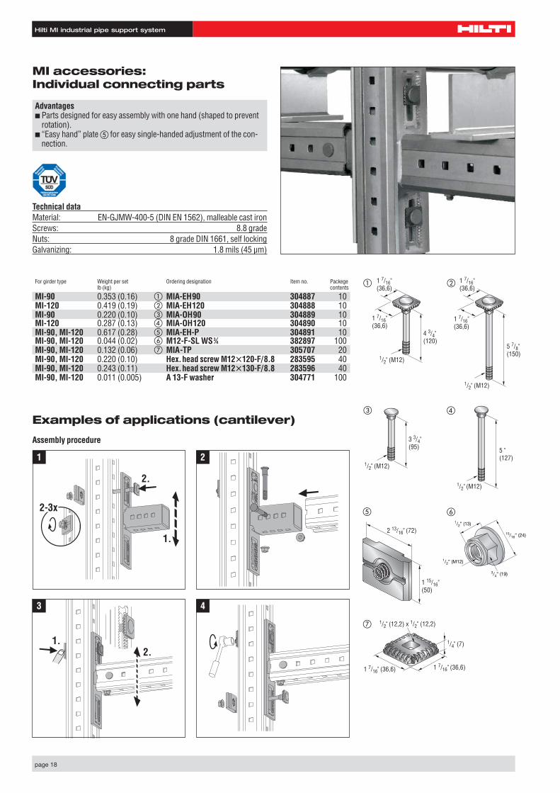
MI-90 0.353 (0.16) � MIA-EH90 304887 10MI-120 0.419 (0.19) � MIA-EH120 304888 10MI-90 0.220 (0.10) � MIA-OH90 304889 10MI-120 0.287 (0.13) � MIA-OH120 304890 10MI-90, MI-120 0.617 (0.28) � MIA-EH-P 304891 10MI-90, MI-120 0.044 (0.02) � M12-F-SL WS3⁄4 382897 100MI-90, MI-120 0.132 (0.06) � MIA-TP 305707 20MI-90, MI-120 0.220 (0.10) Hex.head screw M12�120-F/8.8 283595 40MI-90, MI-120 0.243 (0.11) Hex.head screw M12�130-F/8.8 283596 40MI-90, MI-120 0.011 (0.005) A 13-F washer 304771 100
MI accessories: Individual connecting parts
Advantages■ Parts designed for easy assembly with one hand (shaped to prevent
rotation).■ “Easy hand” plate � for easy single-handed adjustment of the con-
nection.
Technical dataMaterial: EN-GJMW-400-5 (DIN EN 1562), malleable cast ironScrews: 8.8 grade Nuts: 8 grade DIN 1661, self lockingGalvanizing: 1.8 mils (45 µm)
1 7/16" (36,6)
1 7/16" (36,6)
4 3/4" (120)
1/2" (M12)
1 7/16" (36,6)
1 7/16" (36,6)
5 7/8" (150)
1/2" (M12)
3 3/4" (95)
1/2" (M12)
5 " (127)
1/2" (M12)
2 13/16" (72)
1 15/16" (50)
1/2” (M12)
3/4” (19)
15/16” (24)
1/2” (13)
1 7/16" (36,6)1 7/16" (36,6)
1/4" (7)
1/2" (12,2) x 1/2" (12,2)
�
�
�
�
�
�
�
Examples of applications (cantilever)
Assembly procedure
1.
2.
2-3x
1.2.
1 2
3 4
Hilti MI industrial pipe support system
page 19
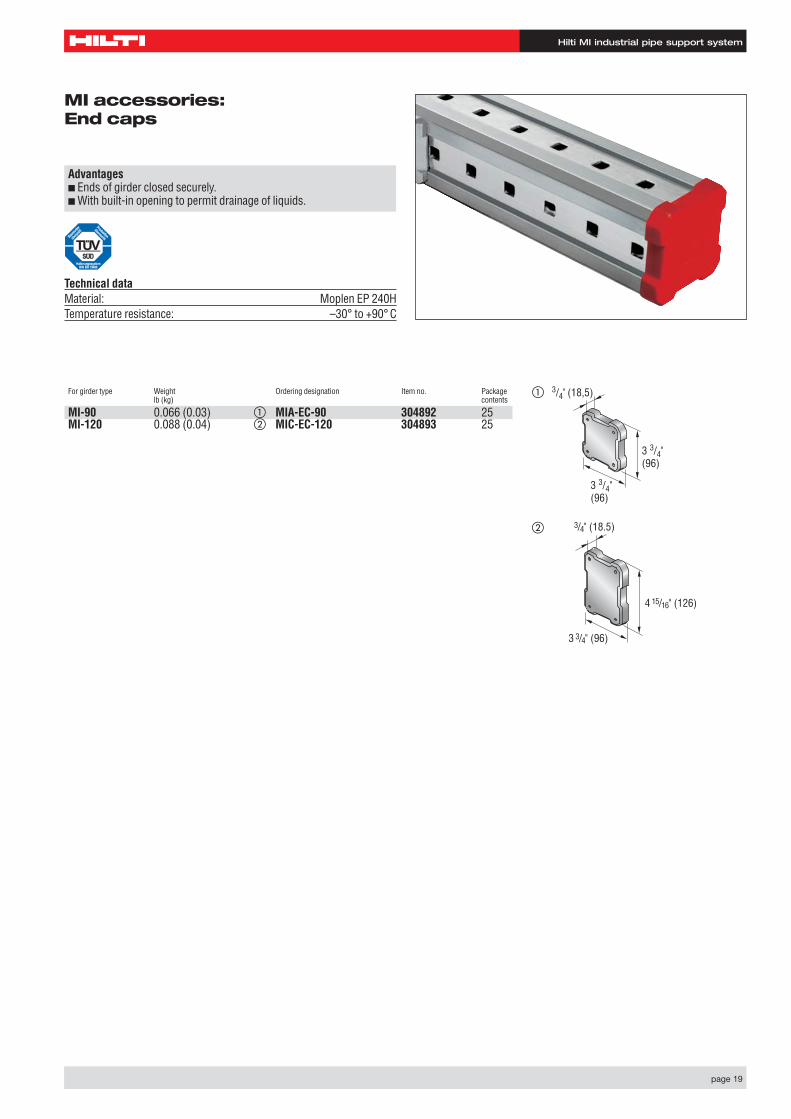
MI accessories: End caps
Advantages■ Ends of girder closed securely.■ With built-in opening to permit drainage of liquids.
Technical dataMaterial: Moplen EP 240HTemperature resistance: –30° to +90° C
For girder type Weight Ordering designation Item no. Package lb (kg) contents
MI-90 0.066 (0.03) � MIA-EC-90 304892 25MI-120 0.088 (0.04) � MIC-EC-120 304893 25
�
�
3 3/4" (96)
3 3/4" (96)
3/4" (18,5)
3/4" (18.5)
4 15/16" (126)
3 3/4" (96)
Hilti MI industrial pipe support system
page 20
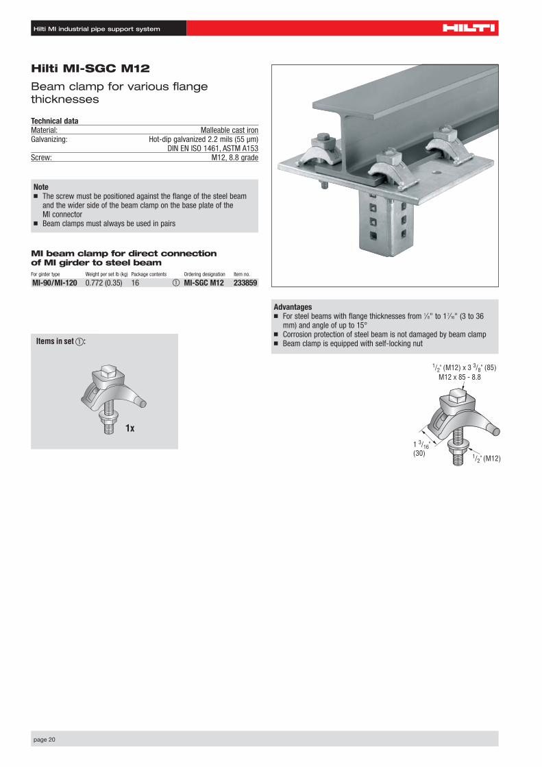
Hilti MI-SGC M12
Beam clamp for various flange thicknesses
Technical dataMaterial: Malleable cast ironGalvanizing: Hot-dip galvanized 2.2 mils (55 µm)
DIN EN ISO 1461, ASTM A153Screw: M12, 8.8 grade
Advantages■ For steel beams with flange thicknesses from 1⁄8" to 17⁄16" (3 to 36
mm) and angle of up to 15°■ Corrosion protection of steel beam is not damaged by beam clamp ■ Beam clamp is equipped with self-locking nut
M12 x 85 - 8.8
1/2" (M12)
1 3/16" (30)
1/2" (M12) x 3 3/8" (85)
MI beam clamp for direct connection of MI girder to steel beamFor girder type Weight per set lb (kg) Package contents Ordering designation Item no.
MI-90/MI-120 0.772 (0.35) 16 � MI-SGC M12 233859
Note■ The screw must be positioned against the flange of the steel beam
and the wider side of the beam clamp on the base plate of the MI connector
■ Beam clamps must always be used in pairs
1x
Items in set �:
Hilti MI industrial pipe support system
page 21
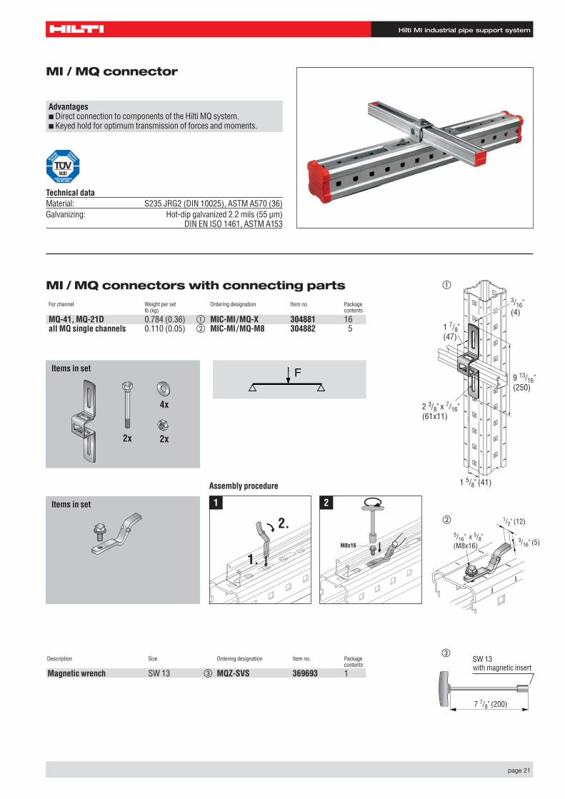
MI / MQ connectors with connecting partsFor channel Weight per set Ordering designation Item no. Package
lb (kg) contents
MQ-41, MQ-21D 0.784 (0.36) � MIC-MI/MQ-X 304881 16all MQ single channels 0.110 (0.05) � MIC-MI/MQ-M8 304882 5
MI / MQ connector
Advantages■ Direct connection to components of the Hilti MQ system.■ Keyed hold for optimum transmission of forces and moments.
Technical dataMaterial: S235 JRG2 (DIN 10025), ASTM A570 (36) Galvanizing: Hot-dip galvanized 2.2 mils (55 µm)
DIN EN ISO 1461, ASTM A153
9 13/16" (250)
1 5/8" (41)
1 7/8" (47)
3/16" (4)
2 3/8" x 7/16"(61x11)
(M8x16)
1/2" (12)
3/16" (5)5/16" x 5/8"
�
�
�
Set besteht aus:
2x
4x
2x
Set besteht aus:
Items in set
Items in set
Assembly procedure
2.
1.M8x16
1 2
Description Size Ordering designation Item no. Package contents
Magnetic wrench SW 13 � MQZ-SVS 369693 1
7 7/8" (200)
SW 13with magnetic insert
Hilti MI industrial pipe support system
page 22
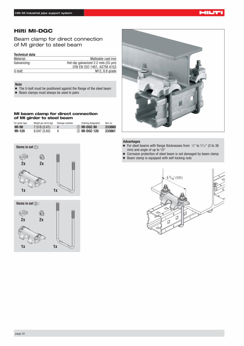
Hilti MI-DGC
Beam clamp for direct connection of MI girder to steel beam
Technical dataMaterial: Malleable cast ironGalvanizing: Hot-dip galvanized 2.2 mils (55 µm)
DIN EN ISO 1461, ASTM A153U-bolt: M12, 8.8 grade
Advantages■ For steel beams with flange thicknesses from 1⁄8" to 17⁄16" (3 to 36
mm) and angle of up to 15°■ Corrosion protection of steel beam is not damaged by beam clamp ■ Beam clamp is equipped with self-locking nuts
Note■ The U-bolt must be positioned against the flange of the steel beam■ Beam clamps must always be used in pairs
MI beam clamp for direct connection of MI girder to steel beamFor girder type Weight per set lb (kg) Package contents Ordering designation Item no.
MI-90 7.518 (3.41) 4 � MI-DGC 90 233860MI-120 8.047 (3.65) 4 � MI-DGC 120 233861
5 3/16" (131)
2x2x
1x 1x
2x2x
1x 1x
Items in set �:
Items in set � :
Hilti MI industrial pipe support system
page 23
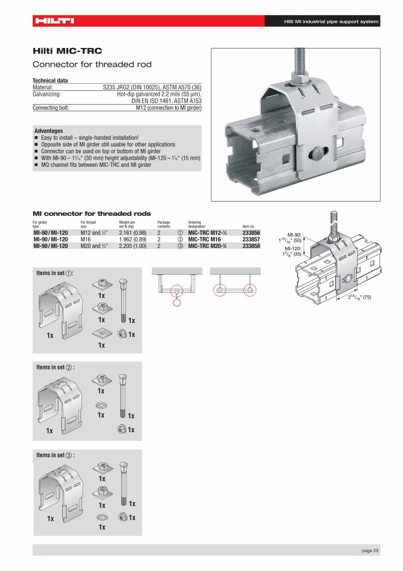
Hilti MIC-TRC
Connector for threaded rod
Technical dataMaterial: S235 JRG2 (DIN 10025), ASTM A570 (36) Galvanizing: Hot-dip galvanized 2.2 mils (55 µm),
DIN EN ISO 1461, ASTM A153Connecting bolt: M12 (connection to MI girder)
Advantages■ Easy to install – single-handed installation!■ Opposite side of MI girder still usable for other applications■ Connector can be used on top or bottom of MI girder■ With MI-90 – 13⁄16" (30 mm) height adjustability (MI-120 – 9⁄16" (15 mm)■ MQ channel fits between MIC-TRC and MI girder
MI connector for threaded rodsFor girder For thread Weight per Package Orderingtype size set lb (kg) contents designation Item no.
MI-90/ MI-120 M12 and 1⁄2" 2.161 (0.98) 2 � MIC-TRC M12-1⁄2 233856MI-90/ MI-120 M16 1.962 (0.89) 2 � MIC-TRC M16 233857MI-90/ MI-120 M20 and 3⁄4" 2.205 (1.00) 2 � MIC-TRC M20-3⁄4 233858
215/16” (75)
MI-90:115/16” (50)
MI-120:13/8” (35)
1x1x
1x
1x
1x
1x
Items in set �:
1x
1x
1x
1x
1x
Items in set � :
1x1x
1x
1x
1x
1x
Items in set � :
Hilti MI industrial pipe support system
page 24
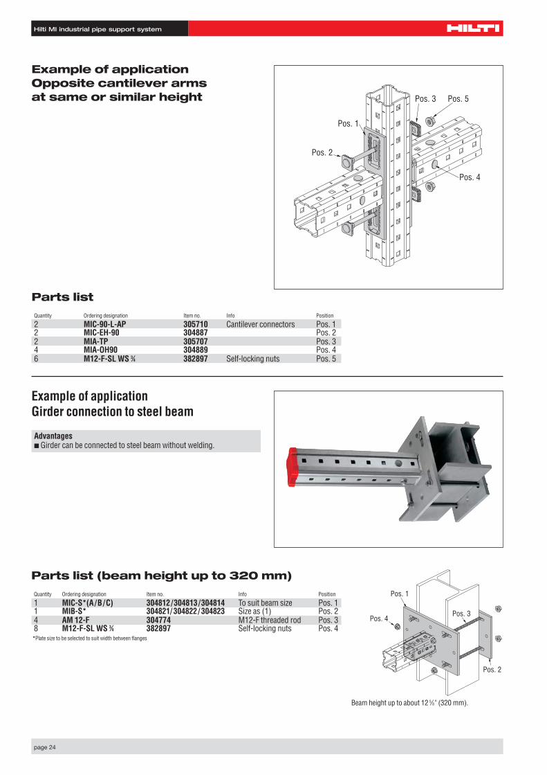
Example of applicationOpposite cantilever arms at same or similar height
Parts listQuantity Ordering designation Item no. Info Position
2 MIC-90-L-AP 305710 Cantilever connectors Pos. 12 MIC-EH-90 304887 Pos. 22 MIA-TP 305707 Pos. 34 MIA-OH90 304889 Pos. 46 M12-F-SL WS 3⁄4 382897 Self-locking nuts Pos. 5
Pos. 1
Pos. 3 Pos. 5
Pos. 4
Pos. 2
Example of applicationGirder connection to steel beam
Pos. 1
Pos. 2
Pos. 3Pos. 4
Beam height up to about 12 5⁄8 " (320 mm).
Parts list (beam height up to 320 mm)Quantity Ordering designation Item no. Info Position
1 MIC-S*(A/B/C) 304812/304813/304814 To suit beam size Pos. 11 MIB-S* 304821/ 304822/ 304823 Size as (1) Pos. 24 AM 12-F 304774 M12-F threaded rod Pos. 38 M12-F-SL WS 3⁄4 382897 Self-locking nuts Pos. 4*Plate size to be selected to suit width between flanges
Advantages■ Girder can be connected to steel beam without welding.
Hilti MI industrial pipe support system
page 25
Pos. 1
Pos. 3
Pos. 5
Pos. 2
Pos. 4
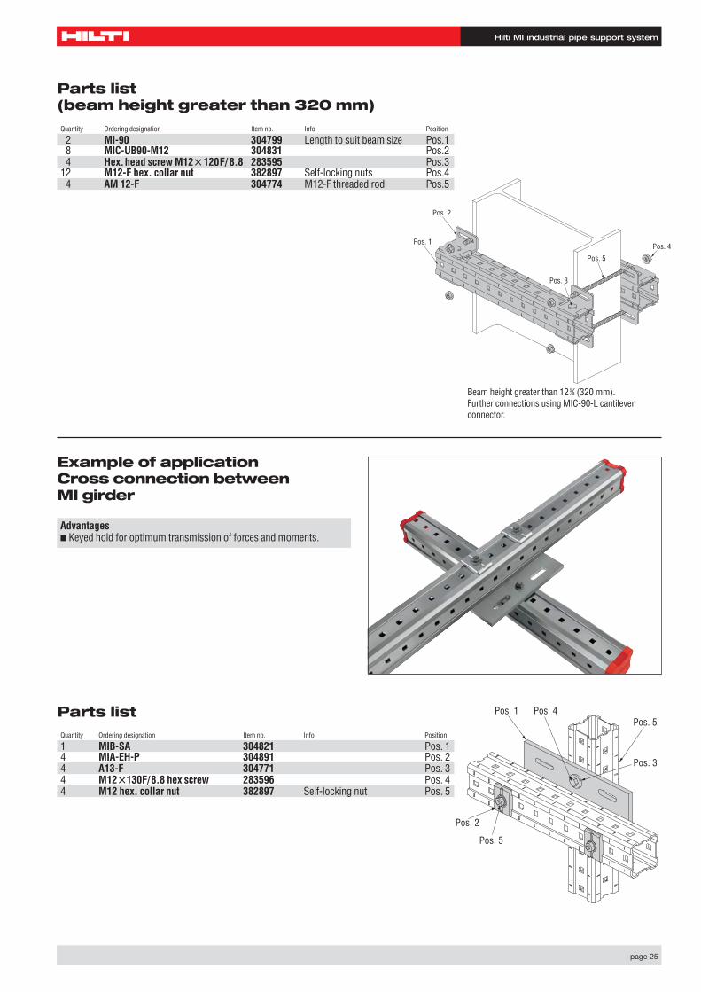
Beam height greater than 125⁄8 (320 mm).Further connections using MIC-90-L cantilever connector.
Parts list (beam height greater than 320 mm)Quantity Ordering designation Item no. Info Position
2 MI-90 304799 Length to suit beam size Pos.18 MIC-UB90-M12 304831 Pos.24 Hex.head screw M12�120F/ 8.8 283595 Pos.3
12 M12-F hex. collar nut 382897 Self-locking nuts Pos.44 AM 12-F 304774 M12-F threaded rod Pos.5
Parts listQuantity Ordering designation Item no. Info Position
1 MIB-SA 304821 Pos. 14 MIA-EH-P 304891 Pos. 24 A13-F 304771 Pos. 34 M12�130F/8.8 hex screw 283596 Pos. 44 M12 hex. collar nut 382897 Self-locking nut Pos. 5
Example of applicationCross connection between MI girder
Pos. 1 Pos. 4
Pos. 3
Pos. 5
Pos. 2
Pos. 5
Advantages■ Keyed hold for optimum transmission of forces and moments.

Hilti System MQChannel installation hot-dip galvanised
HDG plus – the longer lasting difference
Hilti. Outperform. Outlast.
HDG plus – the longer lasting difference
Hilti. Outperform. Outlast.
page 26
System MQ channel installation hot-dip galvanised
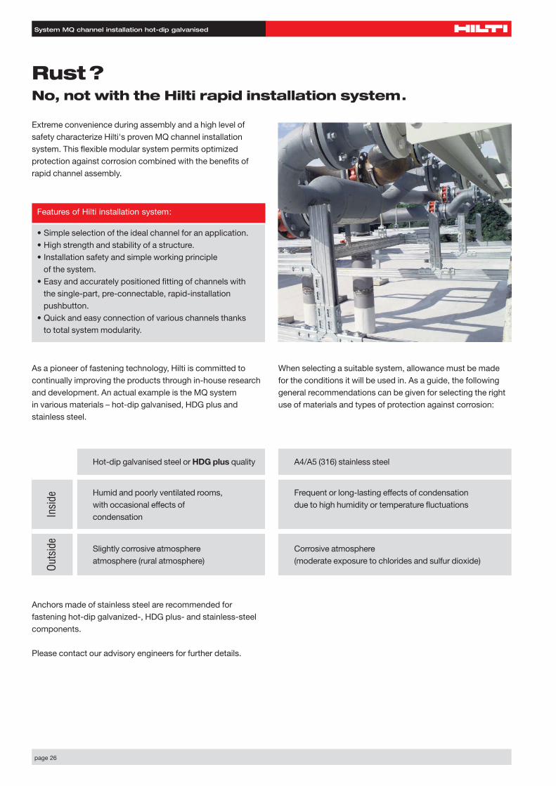
Extreme convenience during assembly and a high level of safety characterize Hilti's proven MQ channel installation system. This flexible modular system permits optimized protection against corrosion combined with the benefits of rapid channel assembly.
Rust?No, not with the Hilti rapid installation system.
As a pioneer of fastening technology, Hilti is committed to continually improving the products through in-house researchand development. An actual example is the MQ system in various materials – hot-dip galvanised, HDG plus and stainless steel.
Anchors made of stainless steel are recommended for fastening hot-dip galvanized-, HDG plus- and stainless-steelcomponents.
Please contact our advisory engineers for further details.
Hot-dip galvanised steel or HDG plus quality A4/A5 (316) stainless steel
Humid and poorly ventilated rooms, Frequent or long-lasting effects of condensationwith occasional effects of due to high humidity or temperature fluctuationscondensation
Slightly corrosive atmosphere Corrosive atmosphere atmosphere (rural atmosphere) (moderate exposure to chlorides and sulfur dioxide)
Insi
deOu
tsid
e
Features of Hilti installation system:
• Simple selection of the ideal channel for an application.• High strength and stability of a structure.• Installation safety and simple working principle
of the system.• Easy and accurately positioned fitting of channels with
the single-part, pre-connectable, rapid-installation pushbutton.
• Quick and easy connection of various channels thanks to total system modularity.
When selecting a suitable system, allowance must be madefor the conditions it will be used in. As a guide, the followinggeneral recommendations can be given for selecting the rightuse of materials and types of protection against corrosion:
page 28
System MQ channel installation HDG plus
MQ-21- MQ-41- MQ-21D- MQ-41D-HDG plus HDG plus HDG plus HDG plus
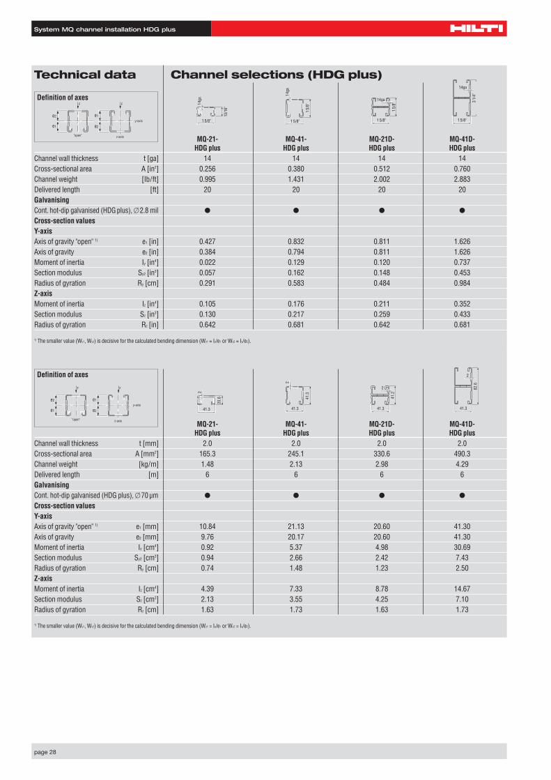
Channel wall thickness t [mm] 2.0 2.0 2.0 2.0Cross-sectional area A [mm2] 165.3 245.1 330.6 490.3Channel weight [kg/m] 1.48 2.13 2.98 4.29Delivered length [m] 6 6 6 6GalvanisingCont. hot-dip galvanised (HDG plus), �70 µm ● ● ● ●
Cross-section valuesY-axisAxis of gravity "open" 1) e1 [mm] 10.84 21.13 20.60 41.30Axis of gravity e2 [mm] 9.76 20.17 20.60 41.30Moment of inertia Iy [cm4] 0.92 5.37 4.98 30.69Section modulus Sy2 [cm3] 0.94 2.66 2.42 7.43Radius of gyration Ry [cm] 0.74 1.48 1.23 2.50Z-axisMoment of inertia Iz [cm4] 4.39 7.33 8.78 14.67Section modulus Sz [cm3] 2.13 3.55 4.25 7.10Radius of gyration Rz [cm] 1.63 1.73 1.63 1.73
1) The smaller value (Wy1, Wy2) is decisive for the calculated bending dimension (Wy1 = Iy/e1 or Wy2 = Iy/e2).
Definition of axes
e2
e1 e2
e1
"open" z-axis
y-axis
FF
Technical data Channel selections (HDG plus)
MQ-21- MQ-41- MQ-21D- MQ-41D-HDG plus HDG plus HDG plus HDG plus
Channel wall thickness t [ga] 14 14 14 14Cross-sectional area A [in2] 0.256 0.380 0.512 0.760Channel weight [Ib/ft] 0.995 1.431 2.002 2.883Delivered length [ft] 20 20 20 20GalvanisingCont. hot-dip galvanised (HDG plus), �2.8 mil ● ● ● ●
Cross-section valuesY-axisAxis of gravity "open" 1) e1 [in] 0.427 0.832 0.811 1.626Axis of gravity e2 [in] 0.384 0.794 0.811 1.626Moment of inertia Iy [in4] 0.022 0.129 0.120 0.737Section modulus Sy2 [in3] 0.057 0.162 0.148 0.453Radius of gyration Ry [cm] 0.291 0.583 0.484 0.984Z-axisMoment of inertia Iz [in4] 0.105 0.176 0.211 0.352Section modulus Sz [in3] 0.130 0.217 0.259 0.433Radius of gyration Rz [in] 0.642 0.681 0.642 0.681
1) The smaller value (Wy1, Wy2) is decisive for the calculated bending dimension (Wy1 = Iy/e1 or Wy2 = Iy/e2).
1 5/8"
1 5/
8"
14ga
1 5/8"
3 1/
4"
14ga
1 5/8"
1 5/
8"
14ga
1 5/8"
13/1
6"
14gaDefinition of axes
e2
e1 e2
e1
"open" z-axis
y-axis
FF
41.3
41.2
2
41.3
82.6
2
41.3
41.3
2
41.3
20.6
2
page 29
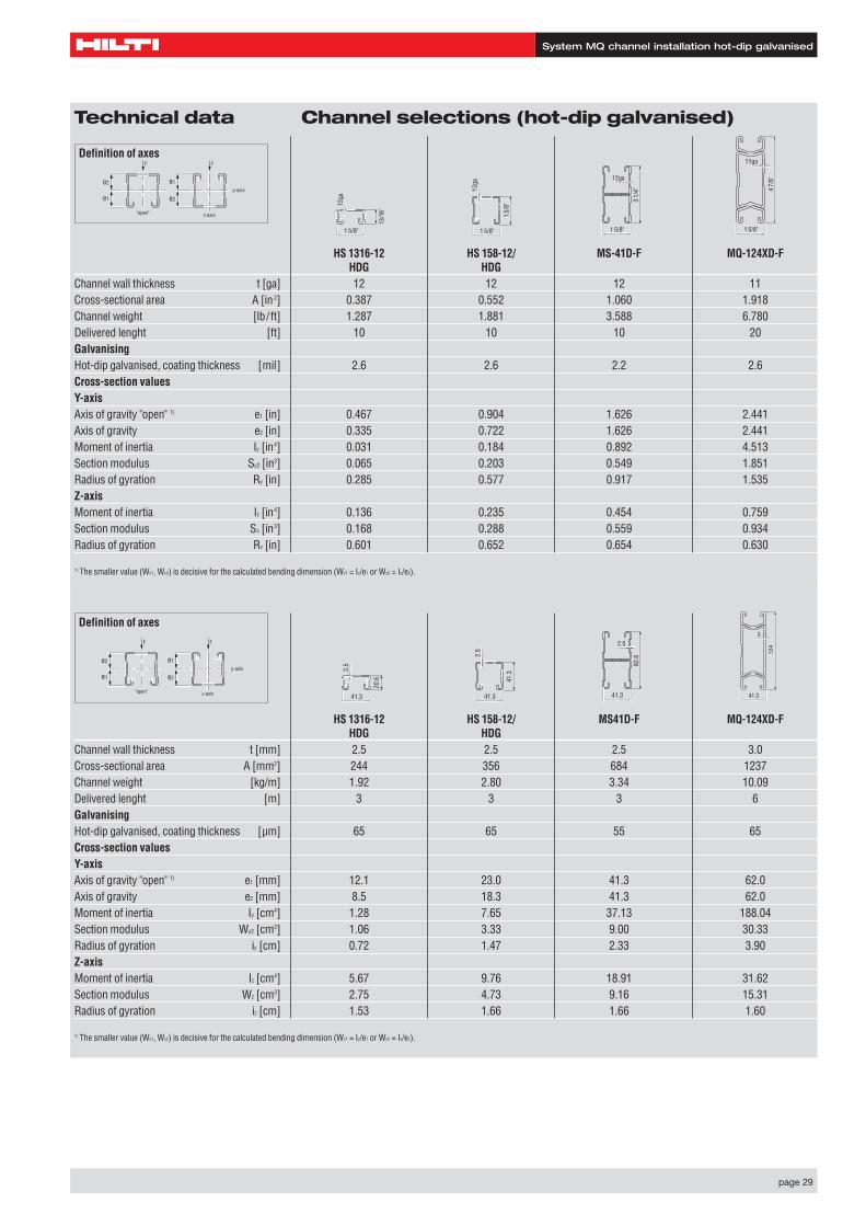
System MQ channel installation hot-dip galvanised
HS 1316-12 HS 158-12/ MS41D-F MQ-124XD-FHDG HDG
Channel wall thickness t [mm] 2.5 2.5 2.5 3.0Cross-sectional area A [mm2] 244 356 684 1237Channel weight [kg/m] 1.92 2.80 3.34 10.09Delivered lenght [m] 3 3 3 6GalvanisingHot-dip galvanised, coating thickness [µm] 65 65 55 65Cross-section valuesY-axisAxis of gravity "open" 1) e1 [mm] 12.1 23.0 41.3 62.0Axis of gravity e2 [mm] 8.5 18.3 41.3 62.0Moment of inertia Iy [cm4] 1.28 7.65 37.13 188.04Section modulus Wy2 [cm3] 1.06 3.33 9.00 30.33Radius of gyration iy [cm] 0.72 1.47 2.33 3.90Z-axisMoment of inertia Iz [cm4] 5.67 9.76 18.91 31.62Section modulus Wz [cm3] 2.75 4.73 9.16 15.31Radius of gyration iz [cm] 1.53 1.66 1.66 1.60
1) The smaller value (Wy1, Wy2) is decisive for the calculated bending dimension (Wy1 = Iy/e1 or Wy2 = Iy/e2).
3
41.3
124
Definition of axes
e2
e1 e2
e1
"open" z-axis
y-axis
FF
Technical data Channel selections (hot-dip galvanised)
HS 1316-12 HS 158-12/ MS-41D-F MQ-124XD-FHDG HDG
Channel wall thickness t [ga] 12 12 12 11Cross-sectional area A [in2] 0.387 0.552 1.060 1.918Channel weight [lb/ft] 1.287 1.881 3.588 6.780Delivered lenght [ft] 10 10 10 20GalvanisingHot-dip galvanised, coating thickness [mil] 2.6 2.6 2.2 2.6Cross-section valuesY-axisAxis of gravity "open" 1) e1 [in] 0.467 0.904 1.626 2.441Axis of gravity e2 [in] 0.335 0.722 1.626 2.441Moment of inertia Iy [in4] 0.031 0.184 0.892 4.513Section modulus Sy2 [in3] 0.065 0.203 0.549 1.851Radius of gyration Ry [in] 0.285 0.577 0.917 1.535Z-axisMoment of inertia Iz [in4] 0.136 0.235 0.454 0.759Section modulus Sz [in3] 0.168 0.288 0.559 0.934Radius of gyration Rz [in] 0.601 0.652 0.654 0.630
1) The smaller value (Wy1, Wy2) is decisive for the calculated bending dimension (Wy1 = Iy/e1 or Wy2 = Iy/e2).
11ga
1 5/8"
4 7/
8"
41.3
82.6
2.5
41.3
41.3
2.5
41.3
20.6
2.5
Definition of axes
e2
e1 e2
e1
"open" z-axis
y-axis
FF
1 5/8"
3 1/
4"
12ga
1 5/8"
1 5/
8"
12ga
1 5/8"
13/1
6"
12ga
page 30
1 5/8" (41.3)
3 1/4" (82.6)
7/8" (22.3)
1 9/16" x 9/16" (40x 13.5)
5/16" (7.5)
3" (75)
1 5/8" (41.3)
4 7/8" (124)
7/8" (22.3) 5/16" (7.5)
11ga (3mm)
System MQ channel installation hot-dip galvanised
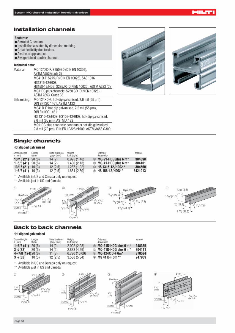
Installation channels
Features:■ Serrated C-section.■ Installation assisted by dimension marking.■ Great flexibility due to slots.■ Aesthetic appearance.■ Swage-joined double channel.
Single channelsHot dipped galvanisedChannel height Length Metal thickness Weight Ordering Item no.in (mm) ft (m) gauge (mm) Ib/ft (kg/m) designation
13/16 (21) 20 (6) 14 (2) 0.995 (1.48) ➀ MQ-21-HDG plus 6 m* 3040981–5/8 (41) 20 (6) 14 (2) 1.430 (2.13) ➁ MQ-41-HDG plus 6 m* 30410113/16 (21) 10 (3) 12 (2.5) 1.287 (1.92) ➂ HS 1316-12/HDG** 3045601–5/8 (41) 10 (3) 12 (2.5) 1.881 (2.80) ➃ HS 158-12/HDG** 3421013
* Available in US and Canada only on request** Available just in US and Canada
Back to back channelsHot dipped galvanisedChannel height Length Metal thickness Weight Ordering Item no.in (mm) ft (m) gauge (mm) Ib/ft (kg/m) designation
1–5/8 (41) 20 (6) 14 (2) 2.002 (2.98) ➀ MQ-21D-HDG plus 6 m* 2483853 1⁄4 (82) 20 (6) 14 (2) 2.833 (4.29) ➁ MQ-41D-HDG plus 6 m* 3041114 –7/8 (124)20 (6) 11 (3) 6.780 (10.09) ➂ MQ-124X D-F 6m* 3705943 1⁄4 (82) 10 (3) 12 (2.5) 3.588 (5.34) ➃ MS 41 D-F 3m** 247909
* Available in US and Canada only on request** Available just in US and Canada
Technical data:Material: MQ 124XD-F: S250 GD (DIN EN 10326),
ASTM A653 Grade 33MS41D-F: S275JR (DIN EN 10025), SAE 1016HS1316-12/HDG, HS158-12/HDG: S235JR (DIN EN 10025), ASTM A283 (C)MQ HDG plus channels: S250 GD (DIN EN 10326), ASTM A653, Grade 33
Galvanising: MQ 124XD-F: hot-dip galvanised, 2.6 mil (65 µm), DIN EN ISO 1461, ASTM A123MS41D-F: hot-dip galvanised, 2.2 mil (55 µm), DIN EN ISO 1461HS 1316-12/HDG, HS158-12/HDG: hot-dip galvanised,2.6 mil (65 µm), ASTM A 123MQ HDG plus channels: continuous hot-dip galvanised,2.8 mil (70 µm), DIN EN 10326 z1000, ASTM A653 G300
➂
1 5/8" (41.3)
3 1/4" (82.6)
7/8" (22.3)
1 9/16" x 9/16" (40 x 13.5)
5/16" (7.5)
3" (75)➁
14ga (2mm)
1 5/8" (41.3)
7/8" (22.3)
2 1/2" x 9/16" (63 x 13.5)
5/16" (7.5)
13/16" (20.6)
4" (100)➀
13/16" (20.6)
7/8" (22.3)
1 5/8" (41.3)
12ga (2.5)
5/16" (7.5)
➂
7/8" (22.3)
1 5/8" (41.3)
1 5/8" (41.3)
12ga (2.5)
5/16" (7.5)
➃
14ga (2mm)
1 5/8" (41.3)
1 5/8" (41.3)
7/8" (22.3)
2 1/2" x 9/16" (63 x 13.5)
5/16" (7.5)
4" (100)
1 5/8" (41.3)
1 5/8" (41.2)
7/8" (22.3)
1 9/16" x 9/16" (40 x 13.5)
5/16" (7.5)
3" (75)➀ ➃
➁
page 31
System MQ channel installation hot-dip galvanised
3 1/8" (80) 4 15/16"
(125)
1 15/16" (50)
1/4" (6)
11 7/16" (450)
13/16" x 9/16" (20x 14)
3 1/8" (80) 4 15/16"
(125)
1 15/16" (50)
1/4" (6)11 13/16" (300)
23 5/8" (600)
39 3/8" (1000)
13/16" x 9/16" (20x 14)
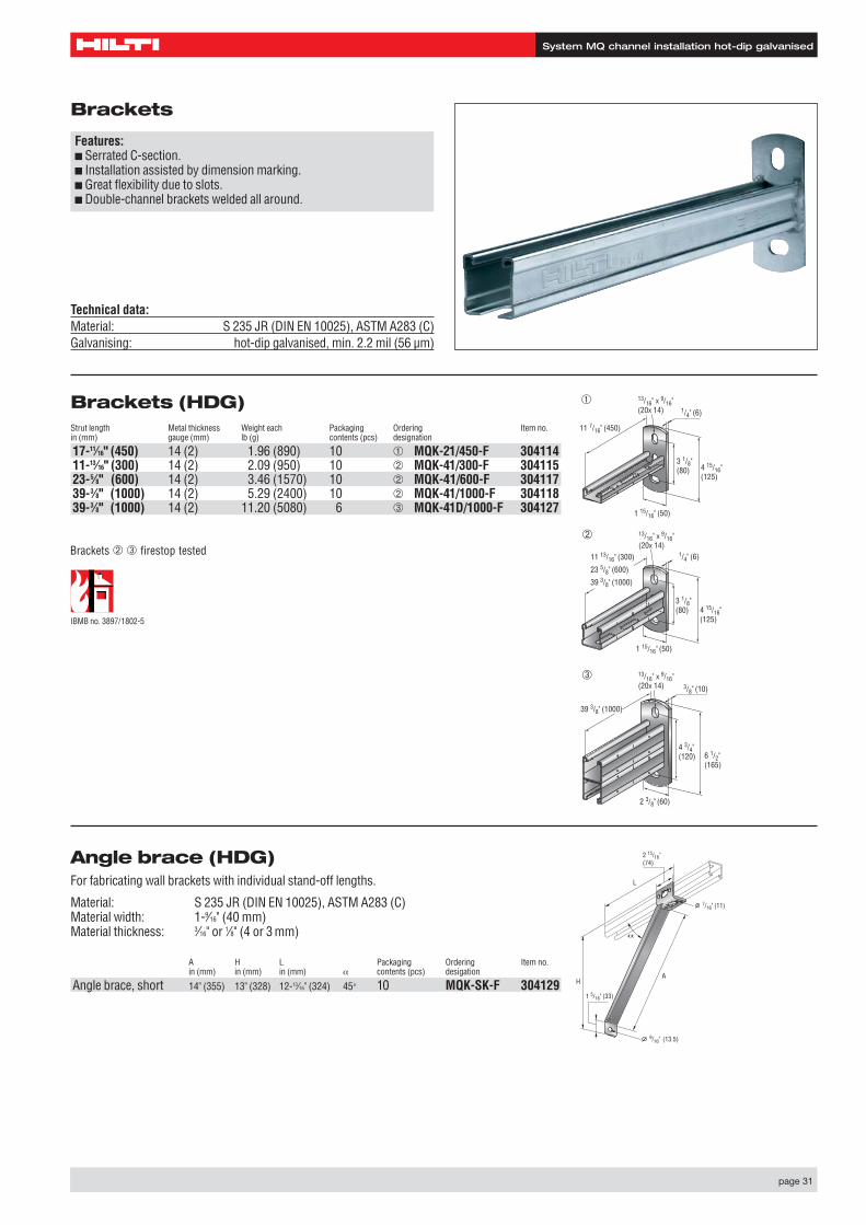
Angle brace (HDG) For fabricating wall brackets with individual stand-off lengths.
Material: S 235 JR (DIN EN 10025), ASTM A283 (C)Material width: 1-9⁄16" (40 mm)Material thickness: 3⁄16" or 1⁄8" (4 or 3 mm)
A H L Packaging Ordering Item no.in (mm) in (mm) in (mm) α contents (pcs) desigation
Angle brace, short 14" (355) 13" (328) 12-13⁄16" (324) 45° 10 MQK-SK-F 304129
L
HA
9/16" (13.5)
2 15/16" (74)
1 5/16" (33)
7/16" (11)
Brackets (HDG)Strut length Metal thickness Weight each Packaging Ordering Item no.in (mm) gauge (mm) lb (g) contents (pcs) designation
17-11⁄16" (450) 14 (2) 1.96 (890) 10 ➀ MQK-21/450-F 30411411-13⁄16" (300) 14 (2) 2.09 (950) 10 ➁ MQK-41/300-F 30411523-5⁄8" (600) 14 (2) 3.46 (1570) 10 ➁ MQK-41/600-F 30411739-3⁄8" (1000) 14 (2) 5.29 (2400) 10 ➁ MQK-41/1000-F 30411839-3⁄8" (1000) 14 (2) 11.20 (5080) 6 ➂ MQK-41D/1000-F 304127
Brackets
Features:■ Serrated C-section.■ Installation assisted by dimension marking.■ Great flexibility due to slots.■ Double-channel brackets welded all around.
Technical data:Material: S 235 JR (DIN EN 10025), ASTM A283 (C)Galvanising: hot-dip galvanised, min. 2.2 mil (56 µm)
➀
➁
4 3/4" (120) 6 1/2"
(165)
2 3/8" (60)
3/8" (10)
39 3/8" (1000)
13/16" x 9/16" (20x 14)
➂
Brackets ➁ ➂ firestop tested
IBMB no. 3897/1802-5
page 32
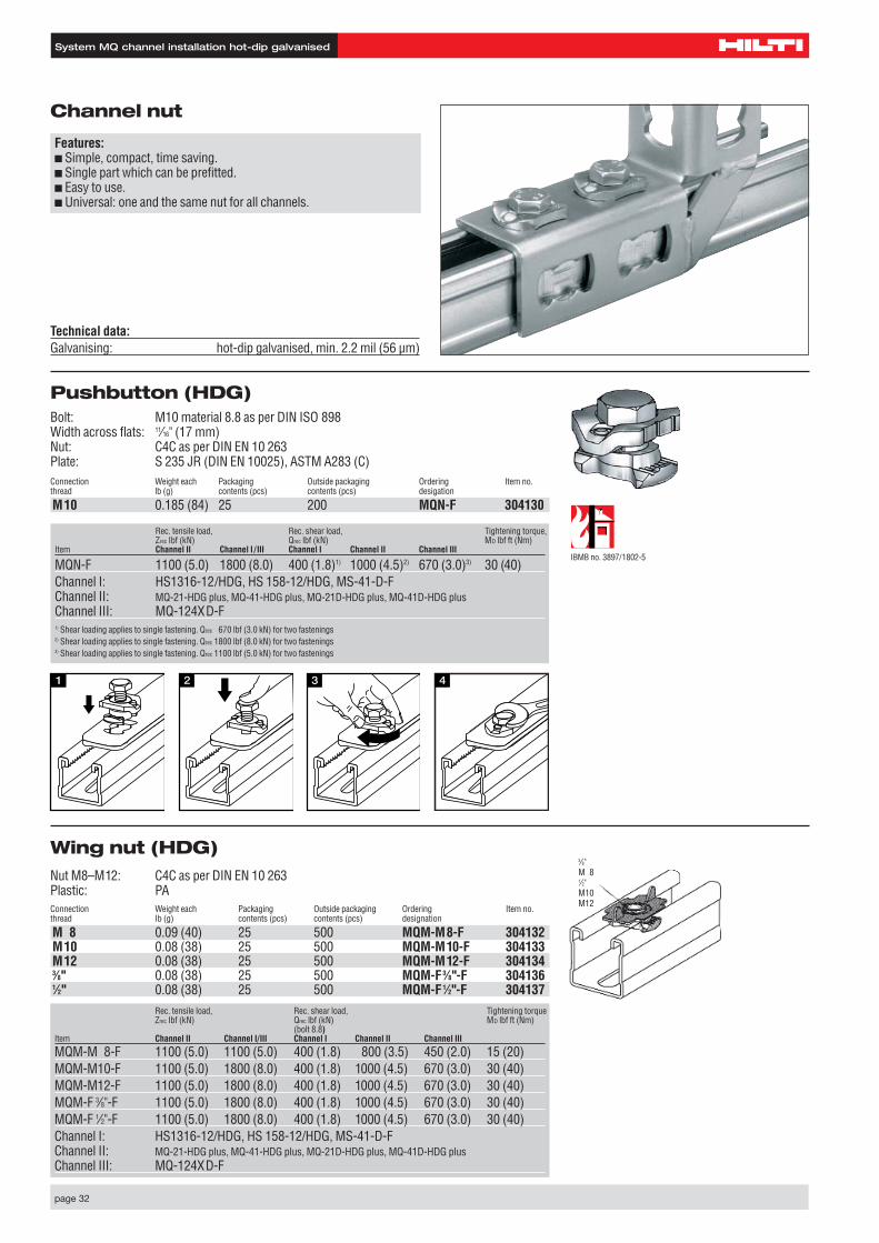
Wing nut (HDG)Nut M8–M12: C4C as per DIN EN 10 263Plastic: PAConnection Weight each Packaging Outside packaging Ordering Item no.thread Ib (g) contents (pcs) contents (pcs) designation
M 8 0.09 (40) 25 500 MQM-M8-F 304132M10 0.08 (38) 25 500 MQM-M10-F 304133M12 0.08 (38) 25 500 MQM-M12-F 3041343⁄8" 0.08 (38) 25 500 MQM-F3⁄8"-F 3041361⁄2" 0.08 (38) 25 500 MQM-F1⁄2"-F 304137
System MQ channel installation hot-dip galvanised
Technical data:Galvanising: hot-dip galvanised, min. 2.2 mil (56 µm)
Channel nut
Features:■ Simple, compact, time saving.■ Single part which can be prefitted.■ Easy to use.■ Universal: one and the same nut for all channels.
Pushbutton (HDG)Bolt: M10 material 8.8 as per DIN ISO 898Width across flats: 11⁄16" (17 mm)Nut: C4C as per DIN EN 10 263Plate: S 235 JR (DIN EN 10025), ASTM A283 (C)Connection Weight each Packaging Outside packaging Ordering Item no.thread lb (g) contents (pcs) contents (pcs) desigation
M10 0.185 (84) 25 200 MQN-F 304130
Rec. tensile load, Rec. shear load, Tightening torqueZrec Ibf (kN) Qrec lbf (kN) MD lbf ft (Nm)
(bolt 8.8)Item Channel II Channel I/III Channel I Channel II Channel III
MQM-M 8-F 1100 (5.0) 1100 (5.0) 400 (1.8) 800 (3.5) 450 (2.0) 15 (20)MQM-M10-F 1100 (5.0) 1800 (8.0) 400 (1.8) 1000 (4.5) 670 (3.0) 30 (40)MQM-M12-F 1100 (5.0) 1800 (8.0) 400 (1.8) 1000 (4.5) 670 (3.0) 30 (40)MQM-F 3⁄8"-F 1100 (5.0) 1800 (8.0) 400 (1.8) 1000 (4.5) 670 (3.0) 30 (40)MQM-F 1⁄2"-F 1100 (5.0) 1800 (8.0) 400 (1.8) 1000 (4.5) 670 (3.0) 30 (40)Channel I: HS1316-12/HDG, HS 158-12/HDG, MS-41-D-FChannel II: MQ-21-HDG plus, MQ-41-HDG plus, MQ-21D-HDG plus, MQ-41D-HDG plusChannel III: MQ-124XD-F
3⁄8"M 81⁄2"M10M12
IBMB no. 3897/1802-5
Rec. tensile load, Rec. shear load, Tightening torque,Zrec Ibf (kN) Qrec lbf (kN) MD lbf ft (Nm)
Item Channel II Channel I / III Channel I Channel II Channel III
MQN-F 1100 (5.0) 1800 (8.0) 400 (1.8)1) 1000 (4.5)2) 670 (3.0)3) 30 (40)Channel I: HS1316-12/HDG, HS 158-12/HDG, MS-41-D-FChannel II: MQ-21-HDG plus, MQ-41-HDG plus, MQ-21D-HDG plus, MQ-41D-HDG plusChannel III: MQ-124XD-F1) Shear loading applies to single fastening. Qrec 670 lbf (3.0 kN) for two fastenings2) Shear loading applies to single fastening. Qrec 1800 lbf (8.0 kN) for two fastenings3) Shear loading applies to single fastening. Qrec 1100 lbf (5.0 kN) for two fastenings
page 33
System MQ channel installation hot-dip galvanised
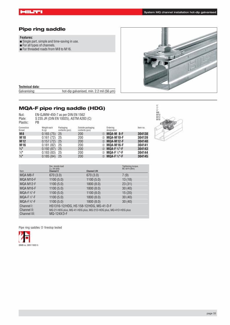
Pipe ring saddle
Features:■ Single part, simple and time-saving in use.■ For all types of channels.■ For threaded roads from M8 to M16.
Technical data:Galvanising: hot-dip galvanised, min. 2.2 mil (56 µm)
MQA-F pipe ring saddle (HDG)Nut: EN-GJMW-450-7 as per DIN EN 1562Plate: S 235 JR (DIN EN 10025), ASTM A283 (C)Plastic: PBConnection Weight each Packaging Outside packaging Ordering Item no.thread Ib (g) contents (pcs) contents (pcs) designation
M8 0.165 (75) 25 200 ➀ MQA-M 8-F 304138M10 0.161 (72) 25 200 ➁ MQA-M10-F 304139M12 0.157 (72) 25 200 ➁ MQA-M12-F 304140M16 0.181 (82) 25 200 ➁ MQA-M16-F 3041413⁄8" 0.192 (87) 25 200 ➁ MQA-F 3⁄8"-F 3041431⁄2" 0.183 (83) 25 200 ➁ MQA-F 1⁄2"-F 3041445⁄8" 0.185 (84) 25 200 ➁ MQA-F 5⁄8"-F 304145
Rec. tensile load Tightening torque,Zrec Ibf (kN) MD lbf ft (Nm)
Item Channel II Channel I/III
MQA M8-F 670 (3.0) 670 (3.0) 7 (9)MQA M10-F 1100 (5.0) 1100 (5.0) 13 (18)MQA M12-F 1100 (5.0) 1800 (8.0) 23 (31)MQA M16-F 1100 (5.0) 1800 (8.0) 30 (40)MQA-F 3⁄8"-F 1100 (5.0) 1100 (8.0) 15 (20)MQA-F 1⁄2"-F 1100 (5.0) 1800 (8.0) 30 (40)MQA-F 5⁄8"-F 1100 (5.0) 1800 (8.0) 30 (40)Channel I: HS1316-12/HDG, HS 158-12/HDG, MS-41-D-FChannel II: MQ-21-HDG plus, MQ-41-HDG plus, MQ-21D-HDG plus, MQ-41D-HDG plusChannel III: MQ-124XD-F
M10M12M16
Pipe ring saddles ➁ firestop tested
IBMB no. 3897/1802-5
3⁄8"1⁄2"5⁄8"M8M10M12M16

page 34
System MQ channel installation hot-dip galvanised
Angle bracket (HDG)
Weight each Packaging Ordering Item no.Ib (g) contents (pcs) designation
Angle bracket, two braces 2.601 (1180) 10 ➀ MQW-S/2-F 304181
Connector, two dimensional (HDG)
Weight each Packaging Ordering Item no.lb (g) contents (pcs) designation
Connector, double, two dimensional 0.983 (446) 10 ➀ MQV-2/2D-F 304150Connector, triple, two dimensional 1.327 (602) 10 ➁ MQV-3/2D-F 304152
Longitudinal channel connector (HDG)
Weight each Packaging Ordering Item no.lb (g) contents (pcs) designation
Channel connector, 12 hole 1.285 (583) 10 ➀ MQV-12-F 304155Channel connector, 4 hole, flat 0.415 (188) 10 ➁ MQV-P4-F 304156
7 7/8" (198)
7 7/8" (198)
3 15/16" (100)
9/16" (13.5)
➀ Frec = 900 lbf (4.0 kN)
3 15/16" (100)
4 7/16" (112)
6 1/2" (167)
4 7/16" (112)
6 1/2" (167)➀
➀
➁
1 3/4" (45)
8 1/16" (205)
8 1/16" (205)
Angles, angle brackets, connectors
Features:■ Universal: few parts for all applications.■ Easy to use.■ Three-dimensional, thus high strength.■ The MQN-F pushbutton can be prefitted
1 3/8" (35) 3/8" (10)
3/4" (19)3/4" (19.4)
Technical data:Material: S 235 JR (DIN EN 10025), ASTM A283 (C)Material thickness: 3⁄16" (4 mm)Galvanising: hot-dip galvanised, min. 2.2 mil (56 µm),
DIN EN ISO 1461, ASTM A153
90º angle (HDG)Weight each Packaging Ordering Item no.lg (g) contents (pcs) designation
Angle, 2 hole, 90° 0.243 (110) 20 ➀ MQW-2-F 304171Angle, 8 hole, 90° 0.926 (420) 10 ➁ MQW-8/90°-F 304175Angle, 3 hole, 90° 0.353 (160) 20 ➂ MQW-3-F 304172
4 1/8" (105)
2 3/8" (61)4 3/8" (111)
➂Frec 1.8 x Qrec(Single value MQN-F )
ASupported at both ends
observe MD
AFrec 1.8 x Qrec(Single value MQN-F )
A
Supported at both ends
A
observe MD
2 3/8" (61)2 3/8" (61)
➀ Frec Qrec(MQN-F )
A
Supported at both ends
A
➁
➁
page 35
System MQ channel installation hot-dip galvanised
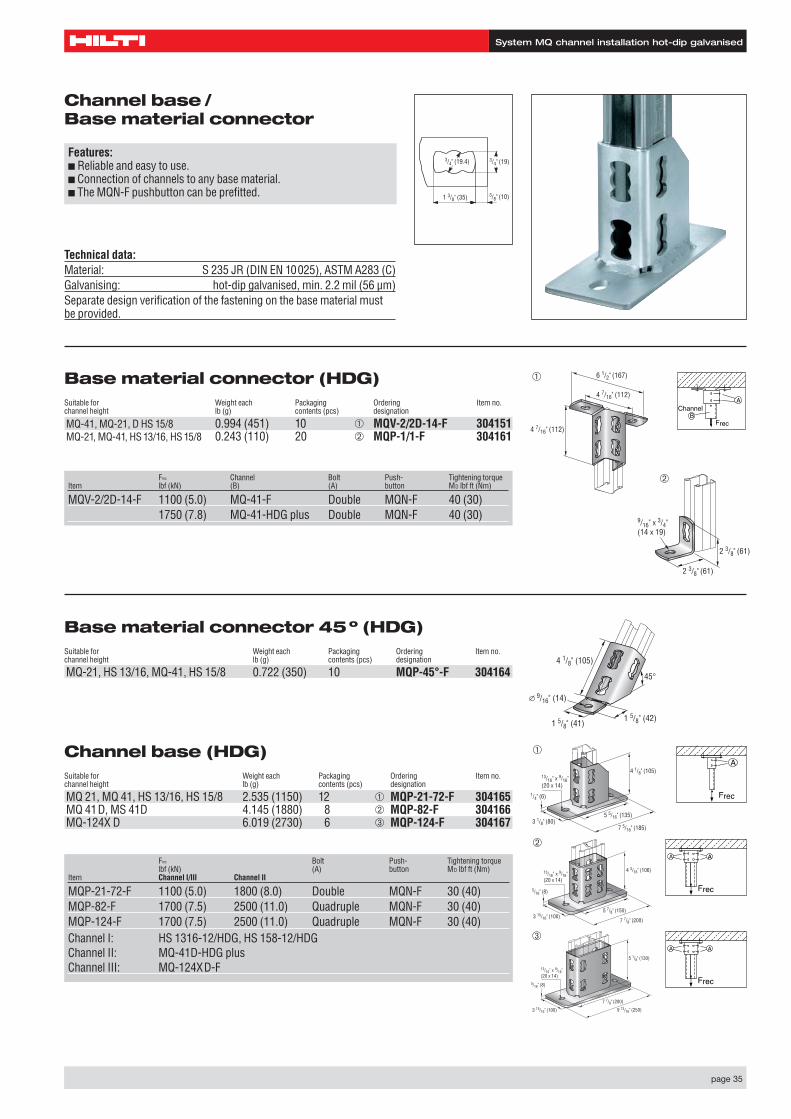
Channel base /Base material connector
Features:■ Reliable and easy to use.■ Connection of channels to any base material.■ The MQN-F pushbutton can be prefitted. 1 3/8" (35) 3/8" (10)
3/4" (19)3/4" (19.4)
Technical data:Material: S 235 JR (DIN EN 10025), ASTM A283 (C)Galvanising: hot-dip galvanised, min. 2.2 mil (56 µm)Separate design verification of the fastening on the base material mustbe provided.
Base material connector (HDG)Suitable for Weight each Packaging Ordering Item no.channel height lb (g) contents (pcs) designation
MQ-41, MQ-21, D HS 15/8 0.994 (451) 10 ➀ MQV-2/2D-14-F 304151MQ-21, MQ-41, HS 13/16, HS 15/8 0.243 (110) 20 ➁ MQP-1/1-F 304161
Frec Channel Bolt Push- Tightening torqueItem lbf (kN) (B) (A) button MD lbf ft (Nm)
MQV-2/2D-14-F 1100 (5.0) MQ-41-F Double MQN-F 40 (30)1750 (7.8) MQ-41-HDG plus Double MQN-F 40 (30)
4 7/16" (112)
4 7/16" (112)
6 1/2" (167)➀
2 3/8" (61)
2 3/8" (61)
9/16" x 3/4" (14 x 19)
➁
Frec
AChannel
B
Base material connector 45º (HDG)Suitable for Weight each Packaging Ordering Item no.channel height lb (g) contents (pcs) designation
MQ-21, HS 13/16, MQ-41, HS 15/8 0.722 (350) 10 MQP-45°-F 304164 45°
1 5/8" (42)
4 1/8" (105)
9/16" (14)
1 5/8" (41)
Channel base (HDG)Suitable for Weight each Packaging Ordering Item no.channel height lb (g) contents (pcs) designation
MQ 21, MQ 41, HS 13/16, HS 15/8 2.535 (1150) 12 ➀ MQP-21-72-F 304165MQ 41D, MS 41D 4.145 (1880) 8 ➁ MQP-82-F 304166MQ-124X D 6.019 (2730) 6 ➂ MQP-124-F 304167
Frec Bolt Push- Tightening torquelbf (kN) (A) button MD lbf ft (Nm)
Item Channel I/III Channel II
MQP-21-72-F 1100 (5.0) 1800 (8.0) Double MQN-F 30 (40)MQP-82-F 1700 (7.5) 2500 (11.0) Quadruple MQN-F 30 (40)MQP-124-F 1700 (7.5) 2500 (11.0) Quadruple MQN-F 30 (40)Channel I: HS 1316-12/HDG, HS 158-12/HDGChannel II: MQ-41D-HDG plusChannel III: MQ-124XD-F
4 1/8" (105)
1/4" (6)
3 1/8" (80)5 5/16" (135)
7 5/16" (185)
13/16" x 9/16" (20 x 14)
5 1/8" (130)
5/16" (8)
3 15/16" (100)
7 7/8" (200)
9 13/16" (250)
13/16" x 9/16" (20 x 14)
➀
➂
4 3/16" (106)
5/16" (8)
3 15/16" (100)7 7/8" (200)
5 7/8" (150)
13/16" x 9/16" (20 x 14)
➁
Frec
A
AA
Frec
AA
Frec
page 36
System MQ channel installation hot-dip galvanised
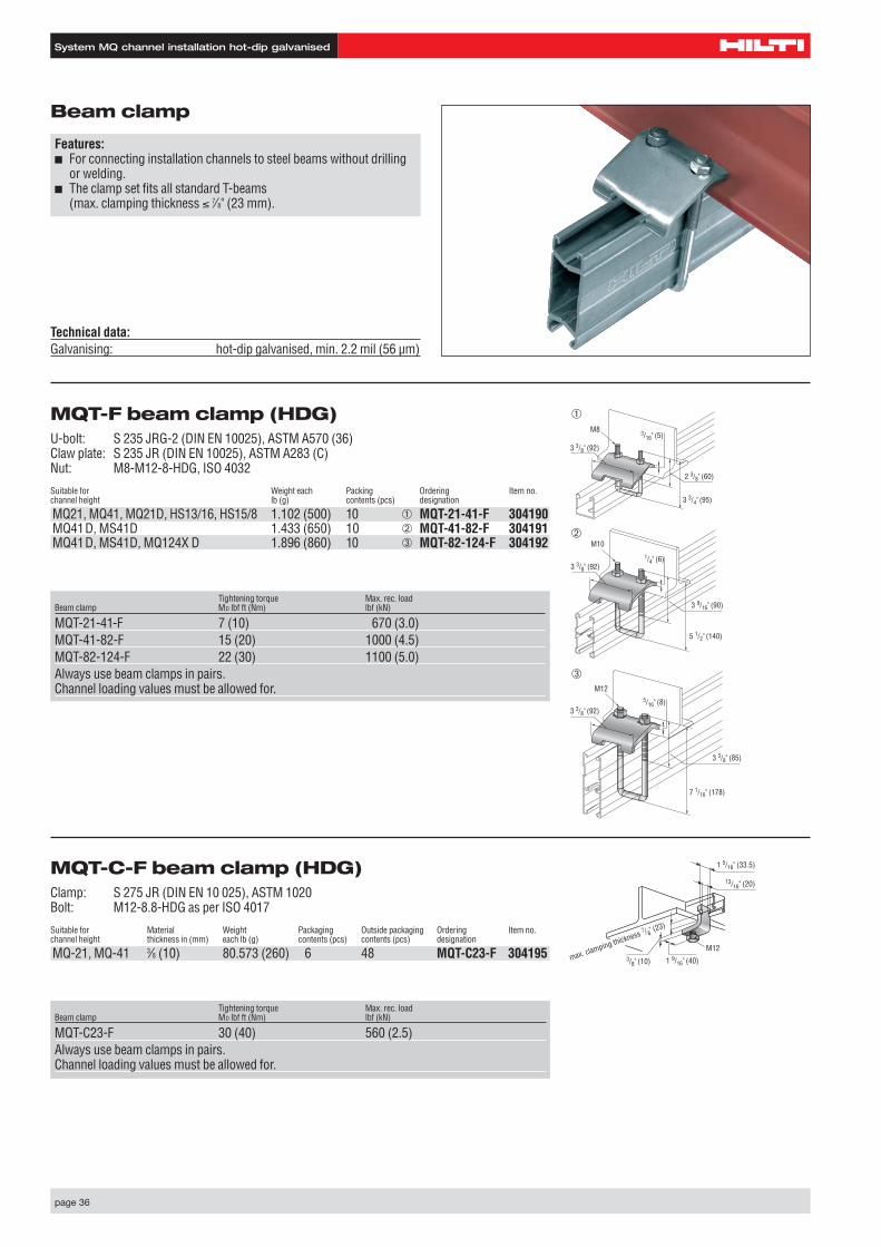
MQT-F beam clamp (HDG)U-bolt: S 235 JRG-2 (DIN EN 10025), ASTM A570 (36)Claw plate: S 235 JR (DIN EN 10025), ASTM A283 (C)Nut: M8-M12-8-HDG, ISO 4032
Suitable for Weight each Packing Ordering Item no.channel height lb (g) contents (pcs) designation
MQ21, MQ41, MQ21D, HS13/16, HS15/8 1.102 (500) 10 ➀ MQT-21-41-F 304190MQ41D, MS41D 1.433 (650) 10 ➁ MQT-41-82-F 304191MQ41D, MS41D, MQ124X D 1.896 (860) 10 ➂ MQT-82-124-F 304192
Beam clamp
Features:■ For connecting installation channels to steel beams without drilling
or welding.■ The clamp set fits all standard T-beams
(max. clamping thickness ≤ 7⁄8" (23 mm).
Technical data:Galvanising: hot-dip galvanised, min. 2.2 mil (56 µm)
M8 3/16" (5)
3 3/4" (95)
3 3/8" (92)
2 3/8" (60)
M10
1/4" (6)
5 1/2" (140)
3 3/8" (92)
3 9/16" (90)
➀
➁
M125/16" (8)
7 1/16" (178)
3 3/8" (92)
3 3/8" (85)
➂
Tightening torque Max. rec. loadBeam clamp MD lbf ft (Nm) lbf (kN)
MQT-21-41-F 7 (10) 670 (3.0)MQT-41-82-F 15 (20) 1000 (4.5)MQT-82-124-F 22 (30) 1100 (5.0)Always use beam clamps in pairs.Channel loading values must be allowed for.
MQT-C-F beam clamp (HDG)Clamp: S 275 JR (DIN EN 10 025), ASTM 1020Bolt: M12-8.8-HDG as per ISO 4017
Suitable for Material Weight Packaging Outside packaging Ordering Item no.channel height thickness in (mm) each lb (g) contents (pcs) contents (pcs) designation
MQ-21, MQ-41 3⁄8 (10) 80.573 (260) 6 48 MQT-C23-F 304195
Tightening torque Max. rec. loadBeam clamp MD lbf ft (Nm) lbf (kN)
MQT-C23-F 30 (40) 560 (2.5)Always use beam clamps in pairs.Channel loading values must be allowed for.
M12
13/16" (20)
3/8" (10)max. clamping thickness 7 /8" (23)
1 5/16" (33.5)
1 9/16" (40)
page 37
System MQ channel installation hot-dip galvanised
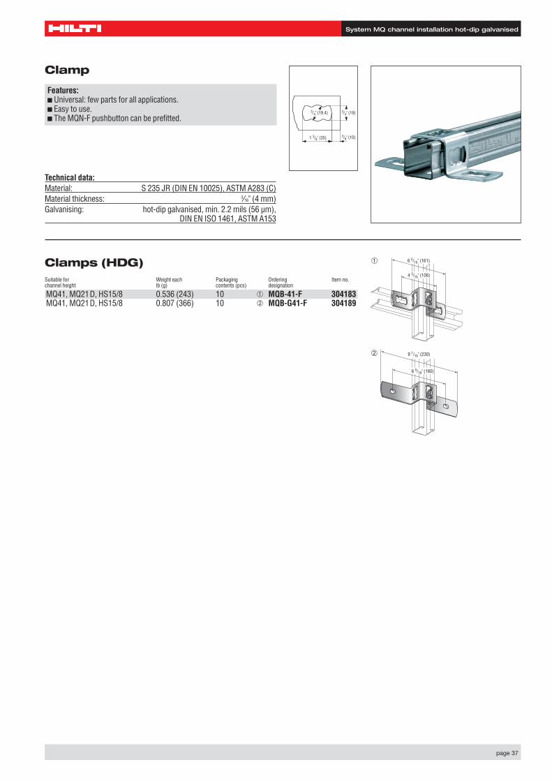
Clamps (HDG)Suitable for Weight each Packaging Ordering Item no.channel height lb (g) contents (pcs) designation
MQ41, MQ21D, HS15/8 0.536 (243) 10 ➀ MQB-41-F 304183MQ41, MQ21D, HS15/8 0.807 (366) 10 ➁ MQB-G41-F 304189
Clamp
Features:■ Universal: few parts for all applications.■ Easy to use.■ The MQN-F pushbutton can be prefitted.
1 3/8" (35) 3/8" (10)
3/4" (19)3/4" (19.4)
Technical data:Material: S 235 JR (DIN EN 10025), ASTM A283 (C)Material thickness: 3⁄16" (4 mm)Galvanising: hot-dip galvanised, min. 2.2 mils (56 µm),
DIN EN ISO 1461, ASTM A153
6 5/16" (161)
4 3/16" (106)
➀
9 1/16" (230)
6 5/16" (160)
➁
page 38
System MQ channel installation hot-dip galvanised
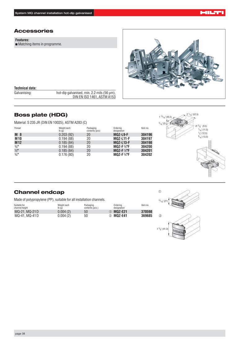
Channel endcap Made of polypropylene (PP), suitable for all installation channels.Suitable for Weight each Packaging Ordering Item no.channel height lb (g) contents (pcs.) designation
MQ-21, MQ-21D 0.004 (2) 50 ➀ MQZ-E21 370598MQ-41, MQ-41D 0.004 (2) 50 ➁ MQZ-E41 369685
13/16" (21)
1 5/8" (41.3)
➀
➁
Boss plate (HDG)Material: S 235 JR (DIN EN 10025), ASTM A283 (C)Thread Weight each Packaging Ordering Item no.
lb (g) contents (pcs) designation
M 8 0.203 (92) 20 MQZ-L9-F 304196M10 0.194 (88) 20 MQZ-L11-F 304197M12 0.185 (84) 20 MQZ-L13-F 3041983⁄8" 0.194 (88) 20 MQZ-F 3⁄8"F 3042001⁄2" 0.185 (84) 20 MQZ-F 1⁄2"F 3042015⁄8" 0.176 (80) 20 MQZ-F 5⁄8"F 304202
Accessories
Features:■ Matching items in programme.
2 1/16" (52.5)1 13/16" (45.5)
3/16" (5)3/8" (9.5)7/16" (11.5)1/2" (12.5)9/16" (13.5)
Technical data:Galvanising: hot-dip galvanised, min. 2.2 mils (56 µm),
DIN EN ISO 1461, ASTM A153
page 39
System MQ channel installation stainlesssteel
page 39
Schienenmontage System MQ Edelstahl
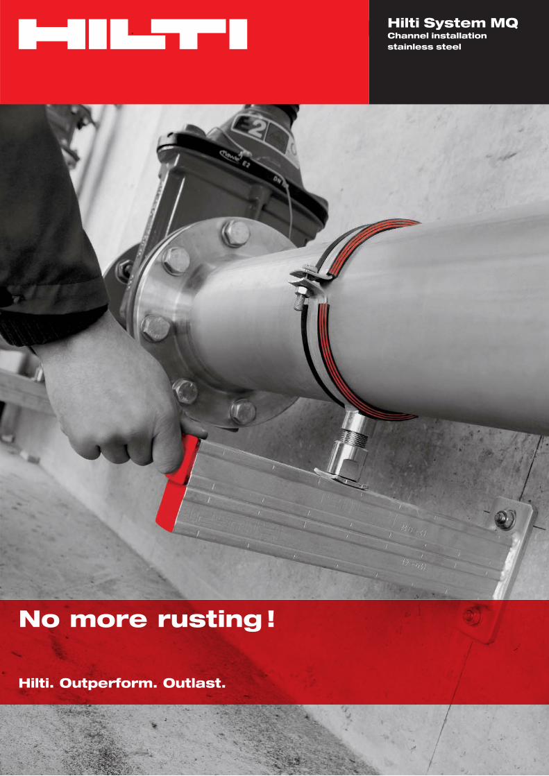
No more rusting !
Hilti. Outperform. Outlast.
Hilti System MQChannel installation stainless steel

page 40
System MQ channel installation stainless steel
Extreme convenience during assembly and a high level of safety characterize Hilti's proven MQ channel installation system. This flexible modular system permits optimized protection against corrosion combined with the benefits of rapid channel assembly.
Rust?No, not with the Hilti rapid installation system.
As a pioneer of fastening technology, Hilti is committed to continually improving the products through in-house researchand development. An actual example is the MQ system in various materials – hot-dip galvanised, HDG plus and stainless steel.
Anchors made of stainless steel are recommended for fastening hot-dip galvanized-, HDG plus- and stainless-steelcomponents.
Please contact our advisory engineers for further details.
A4/A5 (316) stainless steel Hot-dip galvanised steel or HDG plus quality
Frequent or long-lasting effects of Humid and poorly ventilated rooms, with occasionacondensation due to high humidity or effects of condensationtemperature fluctuations
Corrosive atmosphere (moderate exposure Slightly corrosive atmosphere atmosphere to chlorides and sulfur dioxide) (rural atmosphere)
Insi
deOu
tsid
e
Features of Hilti installation system:
• Simple selection of the ideal channel for an application.• High strength and stability of a structure.• Installation safety and simple working principle
of the system.• Easy and accurately positioned fitting of channels with
the single-part, pre-connectable, rapid-installation pushbutton.
• Quick and easy connection of various channels thanks to total system modularity.
When selecting a suitable system, allowance must be madefor the conditions it will be used in. As a guide, the followinggeneral recommendations can be given for selecting the rightuse of materials and types of protection against corrosion:
System MQ channel installation stainless steel
page 41
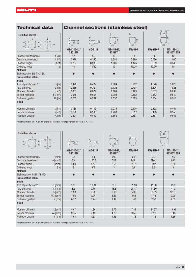
Technical data Channel sections (stainless steel)
MS-1316-12/ MQ-21-R MS-158-12/ MQ-41-R MQ-41D-R MS-158-12/SS316Ti SS316Ti SS316Ti B2B
Channel wall thickness t [ga] 12 14 12 14 14 12Cross-sectional area A [in2] 0.378 0.256 0.552 0.380 0.760 1.060Channel weight [lb/ft] 1.287 0.988 1.881 1.425 2.869 3.588Delivered length [ft] 10 10/20 10 10/20 10/20 10MaterialStainless steel 316Ti / 316L ● ● ● ● ● ●
Cross-section valuesY-axisAxis of gravity "open" 1) e1 [in] 0.476 0.427 0.904 0.832 1.626 1.626Axis of gravity e2 [in] 0.335 0.384 0.722 0.794 1.626 1.626Moment of inertia Iy [in4] 0.031 0.022 0.184 0.129 0.737 0.892Section modulus Sy2 [in3] 0.065 0.057 0.203 0.162 0.453 0.549Radius of gyration Ry [in] 0.285 0.291 0.557 0.583 0.984 0.917Z-axis
Moment of inertia Iz [in4] 0.136 0.105 0.235 0.176 0.352 0.454Section modulus Sz [in3] 0.168 0.130 0.288 0.217 0.433 0.559Radius of gyration Rz [in] 0.601 0.642 0.652 0.681 0.681 0.654
1) The smaller value (Wy1, Wy2) is decisive for the calculated bending dimension (Wy1 = Iy/e1 or Wy2 = Iy/e2).
MS-1316-12/ MQ-21-R MS-158-12/ MQ-41-R MQ-41D-R MS-158-12/SS316Ti SS316Ti SS316Ti B2B
Channel wall thickness t [mm] 2.5 2.0 2.5 2.0 2.0 2.5Cross-sectional area A [mm2] 244 165.3 356 245.1 490.3 684Channel weight [kg/m] 1.88 1.47 2.69 2.12 4.27 5.38Delivered length [m] 3 3/6 3 3/6 3/6 3MaterialStainless steel 1.4571/1.4404 ● ● ● ● ● ●
Cross-section valuesY-axisAxis of gravity "open" 1) e1 [mm] 12.1 10.84 23.0 21.13 41.30 41.3Axis of gravity e2 [mm] 8.5 9.76 18.3 20.17 41.30 41.3Moment of inertia Iy [cm4] 1.28 0.92 7.65 5.37 30.69 37.13Section modulus Wy2 [cm3] 1.06 0.94 3.33 2.66 7.43 9.00Radius of gyration iy [cm] 0.72 0.74 1.47 1.48 2.50 2.33Z-axis
Moment of inertia Iz [cm4] 5.67 4.39 9.76 7.33 14.67 18.91Section modulus Wz [cm3] 2.75 2.13 4.73 3.55 7.10 9.16Radius of gyration iz [cm] 1.53 1.63 1.66 1.73 1.73 1.66
1) The smaller value (Wy1, Wy2) is decisive for the calculated bending dimension (Wy1 = Iy/e1 or Wy2 = Iy/e2).
Definition of axes
e2
e1 e2
e1
"open" z-axis
y-axis
FF
Definition of axes
e2
e1 e2
e1
"open" z-axis
y-axis
FF
1 5/8"
3 1/
4"
12ga
1 5/8"
1 5/
8"
12ga
1 5/8"
13/1
6"
12ga
41.3
82.6
2.5
41.3
41.3
2.5
41.3
20.6
2.5
1 5/8"
1 5/
8"
14ga
1 5/8"
13/1
6"
14ga
41.3
41.3
2
41.3
20.6
2
System MQ channel installation stainless steel
page 42
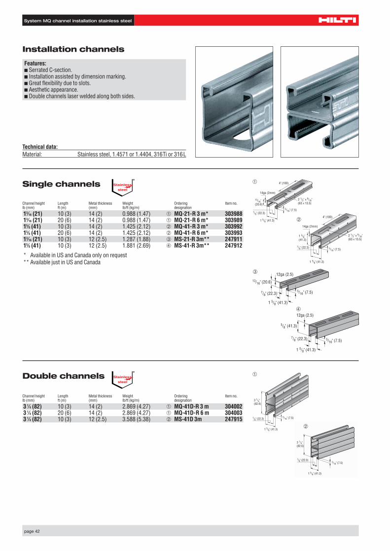
Installation channels
Features:■ Serrated C-section.■ Installation assisted by dimension marking.■ Great flexibility due to slots.■ Aesthetic appearance.■ Double channels laser welded along both sides.
Single channels
Channel height Length Metal thickness Weight Ordering Item no.lb (mm) ft (m) (mm) lb/ft (kg/m) designation
13⁄16 (21) 10 (3) 14 (2) 0.988 (1.47) ➀ MQ-21-R 3 m* 30398813⁄16 (21) 20 (6) 14 (2) 0.988 (1.47) ➀ MQ-21-R 6 m* 30398915⁄8 (41) 10 (3) 14 (2) 1.425 (2.12) ➁ MQ-41-R 3 m* 30399215⁄8 (41) 20 (6) 14 (2) 1.425 (2.12) ➁ MQ-41-R 6 m* 30399313⁄16 (21) 10 (3) 12 (2.5) 1.287 (1.88) ➂ MS-21-R 3m** 24791115⁄8 (41) 10 (3) 12 (2.5) 1.881 (2.69) ➃ MS-41-R 3m** 247912
* Available in US and Canada only on request** Available just in US and Canada
Double channels
Channel height Length Metal thickness Weight Ordering Item no.lb (mm) ft (m) (mm) lb/ft (kg/m) designation
3 1⁄4 (82) 10 (3) 14 (2) 2.869 (4.27) ➀ MQ-41D-R 3 m 3040023 1⁄4 (82) 20 (6) 14 (2) 2.869 (4.27) ➀ MQ-41D-R 6 m 3040033 1⁄4 (82) 10 (3) 12 (2.5) 3.588 (5.38) ➁ MS-41D 3m 247915
Technical data:Material: Stainless steel, 1.4571 or 1.4404, 316Ti or 316L
Stainlesssteel
®
Stainlesssteel
®
1 5/8" (41.3)
3 1/4" (82.6)
7/8" (22.3)5/16" (7.5)
➀
➀➀14ga (2mm)
1 5/8" (41.3)
7/8" (22.3)
2 1/2" x 9/16" (63 x 13.5)
5/16" (7.5)
13/16" (20.6)
4" (100)➀
➁14ga (2mm)
1 5/8" (41.3)
1 5/8" (41.3)
7/8" (22.3)
2 1/2" x 9/16" (63 x 13.5)
5/16" (7.5)
4" (100)
13/16" (20.6)
7/8" (22.3)
1 5/8" (41.3)
12ga (2.5)
5/16" (7.5)
➂
7/8" (22.3)
5/8" (41.3)
1 5/8" (41.3)
12ga (2.5)
5/16" (7.5)
➃
1 5/8" (41.3)
3 1/4" (82.6)
7/8" (22.3)5/16" (7.5)
➁
System MQ channel installation stainless steel
page 43
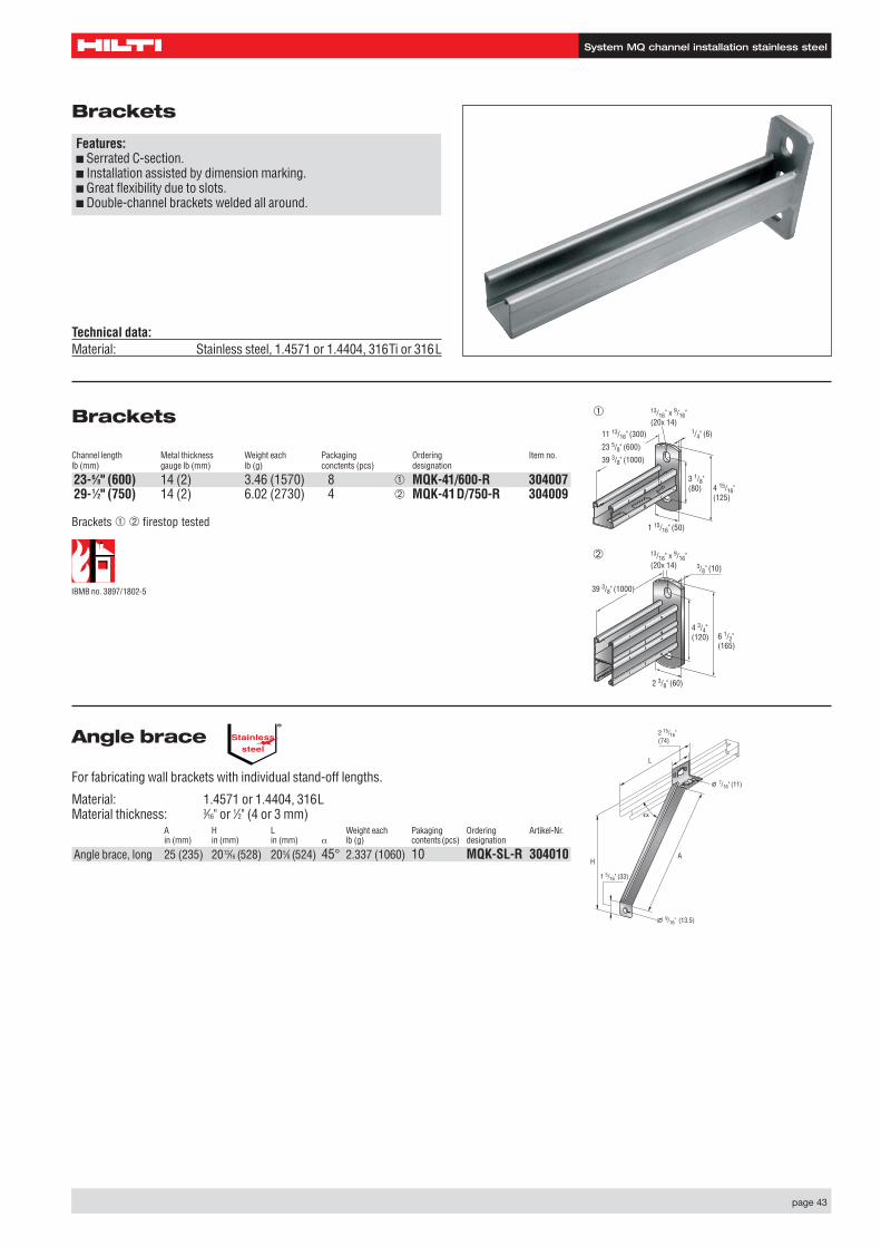
Brackets
Channel length Metal thickness Weight each Packaging Ordering Item no.lb (mm) gauge lb (mm) lb (g) conctents (pcs) designation
23-6⁄8" (600) 14 (2) 3.46 (1570) 8 ➀ MQK-41/600-R 30400729-1⁄2" (750) 14 (2) 6.02 (2730) 4 ➁ MQK-41D/750-R 304009
Brackets
Features:■ Serrated C-section.■ Installation assisted by dimension marking.■ Great flexibility due to slots.■ Double-channel brackets welded all around.
Technical data:Material: Stainless steel, 1.4571 or 1.4404, 316Ti or 316L
Brackets ➀ ➁ firestop tested
Angle brace
For fabricating wall brackets with individual stand-off lengths.
Material: 1.4571 or 1.4404, 316LMaterial thickness: 3⁄16" or 1⁄2" (4 or 3 mm)
A H L Weight each Pakaging Ordering Artikel-Nr.in (mm) in (mm) in (mm) α lb (g) contents(pcs) designation
Angle brace, long 25 (235) 2013⁄16 (528) 205⁄8 (524) 45° 2.337 (1060) 10 MQK-SL-R 304010
L
HA
9/16" (13.5)
2 15/16" (74)
1 5/16" (33)
7/16" (11)
Stainlesssteel
®
IBMB no. 3897/1802-5
3 1/8" (80) 4 15/16"
(125)
1 15/16" (50)
1/4" (6)11 13/16" (300)
23 5/8" (600)
39 3/8" (1000)
13/16" x 9/16" (20x 14)
➀
4 3/4" (120) 6 1/2"
(165)
2 3/8" (60)
3/8" (10)
39 3/8" (1000)
13/16" x 9/16" (20x 14)
➁

System MQ channel installation stainless steel
page 44
Channel nut
Features:■ Simple, compact, time saving.■ Single part which can be prefitted.■ Easy to use.■ Universal: one and the same nut for all channels.
Pushbutton
Bolt: M10 material A4-70 as per DIN EN ISO 3506-1Width across flats: (11⁄16") 17 mmNut: 1.4581 as per DIN EN 10 283Plate: 1.4401 (A4) as per DIN 17 440
Connection Weight each Packaging Outside packaging Ordering Item no.thread lb (g) contents (pcs) contents (pcs) designation
M10 0.170 (77) 25 200 MQN-R 304012
Wing nut
Nut, M6–M12: 1.4581 as per DIN EN 10 283Plastic: PAConnection Weight each Packaging Outside packaging Ordering Item no.thread lb (g) contents (pcs) contents (pcs) designation
M 6 0.06 (29) 25 500 MQM-M6-R 304014M 8 0.06 (27) 25 500 MQM-M8-R 304015M10 0.05 (25) 25 500 MQM-M10-R 304016M12 0.05 (23) 25 500 MQM-M12-R 3040173⁄8" 0.05 (25) 25 500 MQM-F3⁄8"-R 3040191⁄2" 0.05 (23) 25 500 MQM-F1⁄2"-R 304020
Rec. tensile load, Rec. shear load, Tightening torqueZrec Ibf (kN) Qrec lbf (kN) MD lbf ft (Nm)
Item Channel I Channel II (bolt A4-70)
MQM-M 6-R 670 (3.0) 670 (3.0) 340 (1.5) 7 (10)MQM-M 8-R 1100 (5.0) 1100 (5.0) 800 (3.5) 15 (20)MQM-M10-R 1100 (5.0) 1800 (8.0) 1100 (5.0) 30 (40)MQM-M12-R 1100 (5.0) 1800 (8.0) 1100 (5.0) 30 (40)MQM-F3⁄8"-R 1100 (5.0) 1800 (8.0) 1100 (5.0) 30 (40)MQM-F1⁄2"-R 1100 (5.0) 1800 (8.0) 1100 (5.0) 30 (40)Channel I: MQ-21, MQ-41, MQ-21D, MQ-41D (stainless steel)Channel II: MS21, MS41, MS41D (stainless steel)
Rec. tensile load, Rec. shear load, Tightening torqueZrec Ibf (kN) Qrec lbf (kN) MD lbf ft (Nm)
Item Channel I Channel II
MQN-R 1100 (5.0) 1800 (8.0) 1100 (5.0) 1) 30 (40)Channel I: MQ-21, MQ-41, MQ-21D, MQ-41D (stainless steel)Channel II: MS21, MS41, MS41D1) Shear loading applies to single fastening. Qrec lbf (kN) 1980(9.0) for two fastenings
Technical data:Material: Stainless steel
Stainlesssteel
®
Stainlesssteel
®
IBMB no. 3897/1802-5
3⁄8" M 81⁄2" M101⁄2" M12

System MQ channel installation stainless steel
page 45
MQA-R pipe ring saddleNut: 1.4581 as per DIN EN 10 283Plate: 1.4401 (A4) as per DIN 17 440Plastic: PBConnection Weight each Packaging Outside packaging Ordering Item no.thread lb (g) contents (pcs) contents (pcs) designation
M12 0.157 (71) 25 200 ➁ MQA-M12-R 304023
Rec. tensile load, Tightening torque Zrec Ibf (kN) MD lbf ft (Nm)
Item Channel I Channel II
MQA-M12-R 1100 (5.0) 1800 (8.0) 23 (31)Channel I: MQ-21, MQ-41, MQ-21D, MQ-41D (stainless steel)Channel II: MS21, MS41, MS41D (stainless steel)
M10M12M16
Pipe ring saddle
Features:■ Single part, simple and time-saving in use.■ For all types of channels.
Technical data:Material: Stainless steel
Pipe ring saddles ➁ firestop tested
Stainlesssteel
®
IBMB no. 3897/1802-5
M12
System MQ channel installation stainless steel
page 46
Stainlesssteel
®
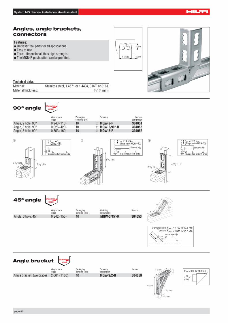
Angles, angle brackets, connectors
Features:■ Univesal: few parts for all applications.■ Easy to use.■ Three-dimensional, thus high strength.■ The MQN-R pushbutton can be prefitted. 1 3/8" (35) 3/8" (10)
3/4" (19)3/4" (19.4)
Technical data:Material: Stainless steel, 1.4571 or 1.4404, 316Ti or 316LMaterial thickness: 3⁄16" (4 mm)
(double bolted A )
A
Compression: Frec. 1700 Ibf (7.5 kN)Tension: Frec. 1350 Ibf (6.0 kN)
45º angle
Weight each Packaging Ordering Item no.lb (g) contents (pcs) designation
Angle, 3 hole, 45° 0.342 (155) 10 MQW-3/45°-R 304053
106
56
45°
90º angle
Weight each Packaging Ordering Item no.lb (g) contents (pcs) designation
Angle, 2 hole, 90° 0.243 (110) 10 ➀ MQW-2-R 304051Angle, 8 hole, 90° 0.926 (420) 10 ➁ MQW-8/90°-R 304055Angle, 3 hole, 90° 0.353 (160) 10 ➂ MQW-3-R 304052
Angle bracket
Weight each Packaging Ordering Item no.lb (g) contents (pcs) designation
Angle bracket, two braces 2.601 (1180) 10 MQW-S/2-R 304059
Stainlesssteel
®
Stainlesssteel
®
4 1/8" (105)
2 3/8" (61)4 3/8" (111)
➂Frec 1.8 x Qrec(Single value MQN-F )
ASupported at both ends
observe MD
AFrec 1.8 x Qrec(Single value MQN-F )
A
Supported at both ends
A
observe MD
2 3/8" (61)2 3/8" (61)
➀ Frec Qrec(MQN-F )
A
Supported at both ends
A
➁
7 7/8" (198)
7 7/8" (198)
3 15/16" (100)
9/16" (13.5)
Frec = 900 lbf (4.0 kN)
3 15/16" (100)
System MQ channel installation stainless steel
page 47
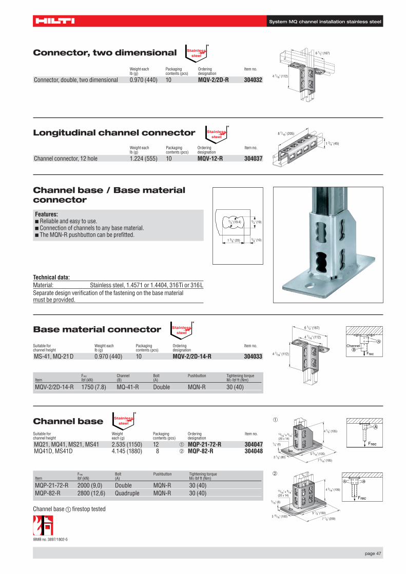
Channel baseSuitable for Weight Packaging Ordering Item no.channel height each (g) contents (pcs) designation
MQ21, MQ41, MS21, MS41 2.535 (1150) 12 ➀ MQP-21-72-R 304047MQ41D, MS41D 4.145 (1880) 8 ➁ MQP-82-R 304048
Frec Bolt Pushbutton Tightening torqueItem lbf (kN) (A) MD lbf ft (Nm)
MQP-21-72-R 2000 (9,0) Double MQN-R 30 (40)MQP-82-R 2800 (12,6) Quadruple MQN-R 30 (40)
Channel base / Base materialconnector
Features:■ Reliable and easy to use.■ Connection of channels to any base material.■ The MQN-R pushbutton can be prefitted.
1 3/8" (35) 3/8" (10)
3/4" (19)3/4" (19.4)
Technical data:Material: Stainless steel, 1.4571 or 1.4404, 316Ti or 316LSeparate design verification of the fastening on the base material must be provided.
Base material connector
Suitable for Weight each Packaging Ordering Item no.channel height lb (g) contents (pcs) designation
MS-41, MQ-21D 0.970 (440) 10 MQV-2/2D-14-R 304033
Frec Channel Bolt Pushbutton Tightening torqueItem lbf (kN) (B) (A) MD lbf ft (Nm)
MQV-2/2D-14-R 1750 (7.8) MQ-41-R Double MQN-R 30 (40)
4 7/16" (112)
4 7/16" (112)
6 1/2" (167)
Frec
AChannel
B
Connector, two dimensional
Weight each Packaging Ordering Item no.lb (g) contents (pcs) designation
Connector, double, two dimensional 0.970 (440) 10 MQV-2/2D-R 304032
Longitudinal channel connector
Weight each Packaging Ordering Item no.lb (g) contents (pcs) designation
Channel connector, 12 hole 1.224 (555) 10 MQV-12-R 304037
4 7/16" (112)
6 1/2" (167)
1 3/4" (45)
8 1/16" (205)
Stainlesssteel
®
Stainlesssteel
®
Stainlesssteel
®
Stainlesssteel
®
4 1/8" (105)
1/4" (6)
3 1/8" (80)5 5/16" (135)
7 5/16" (185)
13/16" x 9/16" (20 x 14)
Frec
A
4 3/16" (106)
5/16" (8)
3 15/16" (100)7 7/8" (200)
5 7/8" (150)
13/16" x 9/16" (20 x 14)
➁
➀
AA
Frec
IBMB no. 3897/1802-5
Channel base � firestop tested
System MQ channel installation stainless steel
page 48
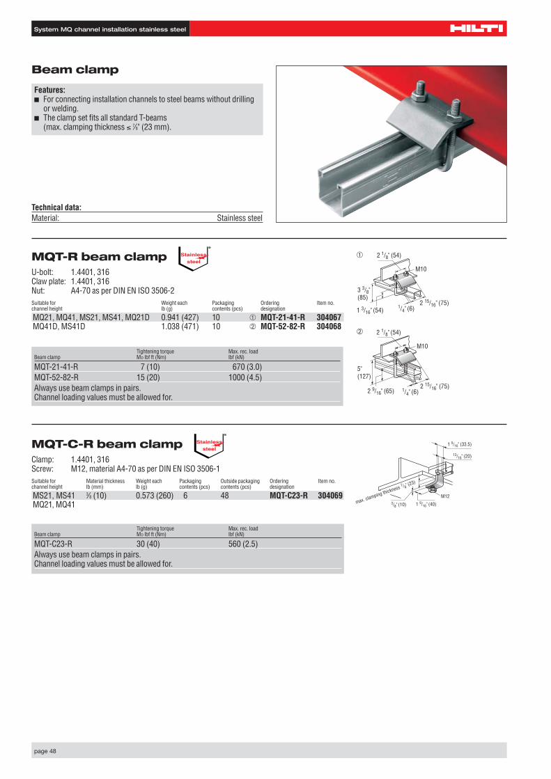
MQT-R beam clampU-bolt: 1.4401, 316Claw plate: 1.4401, 316Nut: A4-70 as per DIN EN ISO 3506-2Suitable for Weight each Packaging Ordering Item no.channel height lb (g) contents (pcs) designation
MQ21, MQ41, MS21, MS41, MQ21D 0.941 (427) 10 ➀ MQT-21-41-R 304067MQ41D, MS41D 1.038 (471) 10 ➁ MQT-52-82-R 304068
Beam clamp
Features:■ For connecting installation channels to steel beams without drilling
or welding.■ The clamp set fits all standard T-beams
(max. clamping thickness ≤ 7⁄8" (23 mm).
➀
➁
Tightening torque Max. rec. loadBeam clamp MD lbf ft (Nm) lbf (kN)
MQT-21-41-R 7 (10) 670 (3.0)MQT-52-82-R 15 (20) 1000 (4.5)Always use beam clamps in pairs.Channel loading values must be allowed for.
Tightening torque Max. rec. loadBeam clamp MD lbf ft (Nm) lbf (kN)
MQT-C23-R 30 (40) 560 (2.5)Always use beam clamps in pairs.Channel loading values must be allowed for.
MQT-C-R beam clampClamp: 1.4401, 316Screw: M12, material A4-70 as per DIN EN ISO 3506-1Suitable for Material thickness Weight each Packaging Outside packaging Ordering Item no.channel height lb (mm) lb (g) contents (pcs) contents (pcs) designation
MS21, MS41 3⁄8 (10) 0.573 (260) 6 48 MQT-C23-R 304069MQ21, MQ41
Technical data:Material: Stainless steel
M12
13/16" (20)
3/8" (10)max. clamping thickness 7 /8" (23)
1 5/16" (33.5)
1 9/16" (40)
Stainlesssteel
®
Stainlesssteel
®
2 1/8" (54)
2 15/16" (75)1 3/16" (54)
1/4" (6)
M10
3 3/8" (85)
2 1/8" (54)
2 15/16" (75)2 9/16" (65) 1/4" (6)
M10
5" (127)
System MQ channel installation stainless steel
page 49
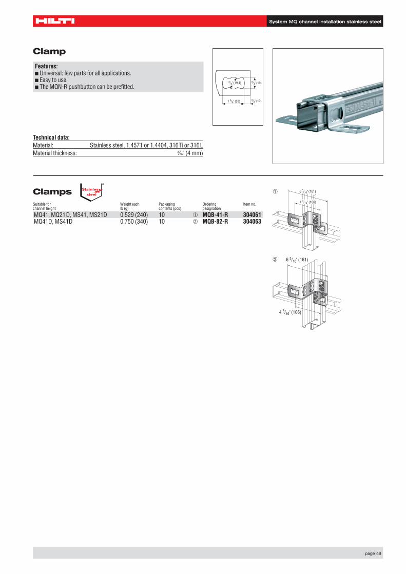
ClampsSuitable for Weight each Packaging Ordering Item no.channel height lb (g) contents (pcs) designation
MQ41, MQ21D, MS41, MS21D 0.529 (240) 10 ➀ MQB-41-R 304061MQ41D, MS41D 0.750 (340) 10 ➁ MQB-82-R 304063
Clamp
Features:■ Universal: few parts for all applications.■ Easy to use.■ The MQN-R pushbutton can be prefitted.
1 3/8" (35) 3/8" (10)
3/4" (19)3/4" (19.4)
Technical data:Material: Stainless steel, 1.4571 or 1.4404, 316Ti or 316LMaterial thickness: 3⁄16" (4 mm)
Stainlesssteel
®
6 5/16" (161)
4 3/16" (106)
➀
6 5/16" (161)
4 3/16" (106)
➁
System MQ channel installation stainless steel
page 50
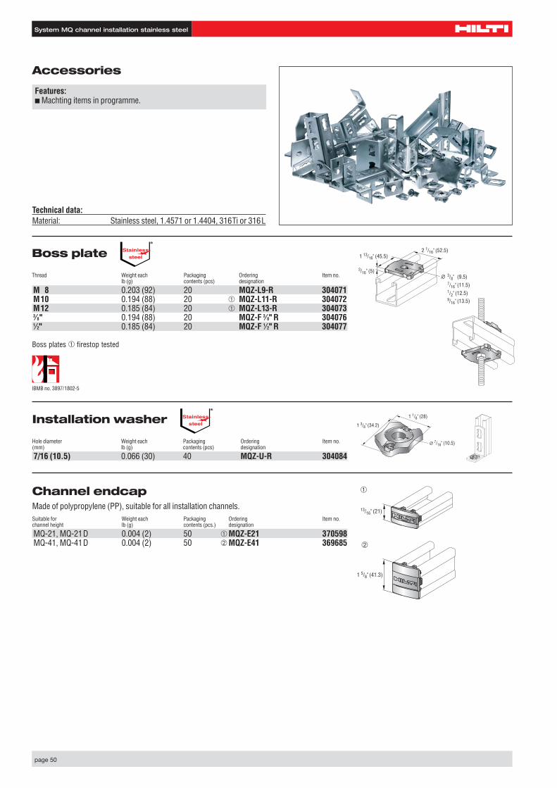
Boss plate
Thread Weight each Packaging Ordering Item no.lb (g) contents (pcs) designation
M 8 0.203 (92) 20 MQZ-L9-R 304071M10 0.194 (88) 20 ➀ MQZ-L11-R 304072M12 0.185 (84) 20 ➀ MQZ-L13-R 3040733⁄8" 0.194 (88) 20 MQZ-F 3⁄8" R 3040761⁄2" 0.185 (84) 20 MQZ-F 1⁄2" R 304077
Installation washer
Hole diameter Weight each Packaging Ordering Item no.(mm) lb (g) contents (pcs) designation
7/16 (10.5) 0.066 (30) 40 MQZ-U-R 304084
1 3/8" (34.2)
1 1/8" (28)
7/16" (10.5)
Accessories
Features:■ Machting items in programme.
Technical data:Material: Stainless steel, 1.4571 or 1.4404, 316Ti or 316L
2 1/16" (52.5)1 13/16" (45.5)
3/16" (5)3/8" (9.5)7/16" (11.5)1/2" (12.5)9/16" (13.5)
Stainlesssteel
®
Stainlesssteel
®
Boss plates ➀ firestop tested
Channel endcap Made of polypropylene (PP), suitable for all installation channels.Suitable for Weight each Packaging Ordering Item no.channel height lb (g) contents (pcs.) designation
MQ-21, MQ-21D 0.004 (2) 50 ➀ MQZ-E21 370598MQ-41, MQ-41D 0.004 (2) 50 ➁ MQZ-E41 369685
IBMB no. 3897/1802-5
13/16" (21)
1 5/8" (41.3)
➀
➁

System MQ channel installation stainless steel
page 51
General safety information
As the Hilti MQ hot-dip galvanised/stainless steel system forms a technical unit, this system must not be used for purposes otherthan those recommended by Hilti or in combination with products that are not suitable for the purpose.
Deviation from the loads warranted by Hilti may result if the system is used in combination with products not recommended by Hilti.When the MN hot-dip galvanised/ stainless steel system is combined with products from the MQ hot-dip galvanised/stainless steelsystem, the load values for the MQ hot-dip galvanised/stainless steel system apply exclusively.
Hilti accepts no liability whatever for damage or loss that could result from failure to observe this safety information.

page 52Hilti Corporation | 9494 Schaan | Liechtenstein | P +423-234 2111 | F +423-234 2965
Hilti. Outperform. Outlast.
Hilt
i = r
egis
tere
d t
rad
emar
k o
f H
ilti C
orp
., S
chaa
n |
W 3
427
060
7 5
-en
| 1
P
rint
ed in
Lie
chte
nste
in
| ©
200
7 |
Rig
ht o
f te
chni
cal a
nd p
rog
ram
me
chan
ges
res
erve
d
S. E
. & O
.