Embed Size (px)
Citation preview
FORM #9910.01-112713 PRINTED IN U.S.A. PAGE 1 OF 16
Superlift 6” Lift System for 2009-Newer
FORD F150 4WD
INTRODUCTION Installation requires a professional mechanic. Prior to beginning, inspect the vehicle’s steering, driveline, and brake systems, paying close attention to the suspension link arms and bushings, anti-sway bars and bushings, tie rod ends, pitman arm, ball joints and wheel bearings. Also check the steering sector-to-frame and all suspension-to-frame attaching points for stress cracks. The overall vehicle must be in excellent working condition; repair or replace all worn parts. Read instructions several times before starting. Be sure you have all needed parts and know where they install. Read each step completely as you go. NOTES:
Prior to beginning the installation, check all parts and hardware in the box with the parts list below. If you find a packaging error, contact Superlift directly. Do not contact the dealer where the system was originally purchased. You will need the control number from each box when calling; this number is located at the bottom of the part number label and to the right of the bar code.
Wheels - Stock 17” and 18” wheels will not work with this lift system. Must run 20” + wheels. * 20” diameter x 9” wide (maximum) with a minimum backspacing 4.5” - maximum
backspacing of 5.5” Tires - 35” diameter x 12.50” wide Front-end realignment is necessary. A foot-pound torque reading is given in parenthesis ( ) after each appropriate fastener. Do not fabricate any components to gain additional suspension height. Prior to drilling or cutting, check behind the surface being worked on for any wires, lines, or
hoses that could be damaged. After drilling, file smooth any burrs and sharp edges. Prior to operating a torch or saw, protect any heat-sensitive components located in the
immediate area by covering them with a water-saturated cloth. Most undercoatings are flammable but can be extinguished using a water-filled spray bottle. Have a spray bottle and an ABC rated fire extinguisher on hand.
Paint or undercoat all metal surfaces. Prior to attaching components, be sure all mating surfaces are free of grit, grease,
undercoating, etc. A factory service manual should be on hand for reference.
FORM #9910.01-112713 PRINTED IN U.S.A. PAGE 2 OF 16
Use the check-off “” found at each step to help you keep your place. Two “” denotes that one check-off box is for the driver side and one is for the passenger side. Unless otherwise noted, always start with the driver side.
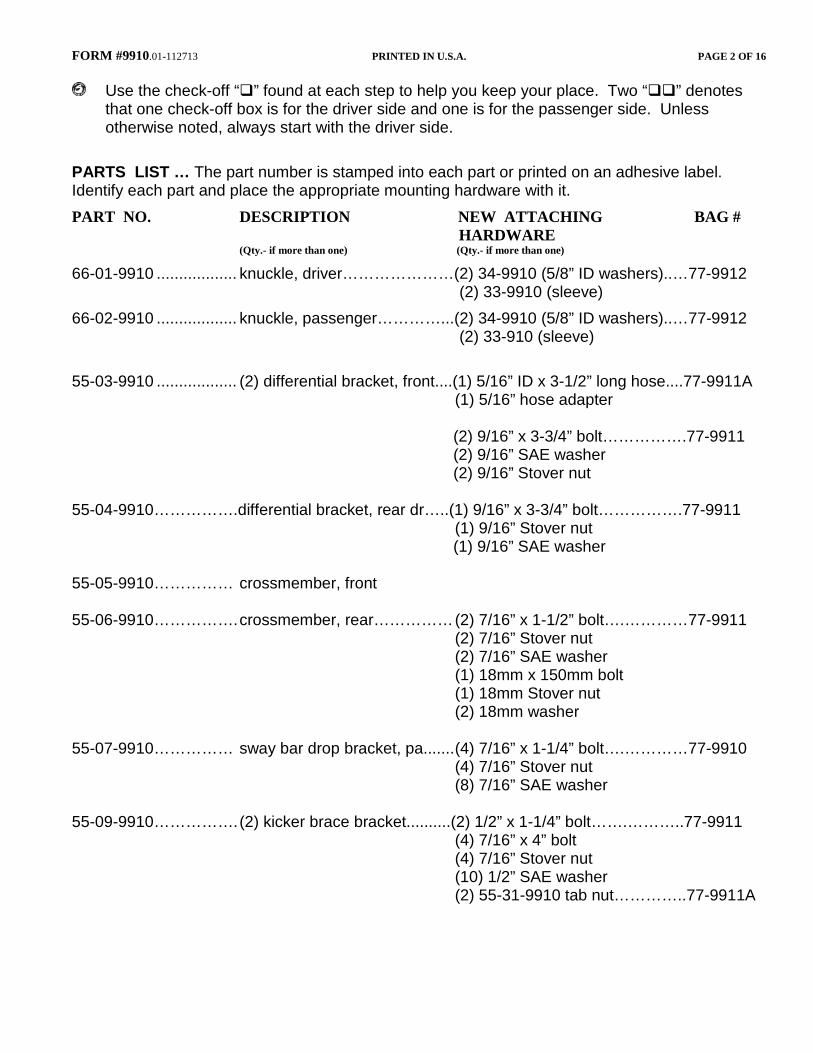
PARTS LIST … The part number is stamped into each part or printed on an adhesive label. Identify each part and place the appropriate mounting hardware with it. PART NO. DESCRIPTION NEW ATTACHING BAG # HARDWARE (Qty.- if more than one) (Qty.- if more than one)
66-01-9910 .................. knuckle, driver…………………(2) 34-9910 (5/8” ID washers)..…77-9912 (2) 33-9910 (sleeve) 66-02-9910 .................. knuckle, passenger…………...(2) 34-9910 (5/8” ID washers)..…77-9912 (2) 33-910 (sleeve) 55-03-9910 .................. (2) differential bracket, front....(1) 5/16” ID x 3-1/2” long hose....77-9911A (1) 5/16” hose adapter (2) 9/16” x 3-3/4” bolt…………….77-9911 (2) 9/16” SAE washer (2) 9/16” Stover nut 55-04-9910…………….differential bracket, rear dr…..(1) 9/16” x 3-3/4” bolt…………….77-9911 (1) 9/16” Stover nut (1) 9/16” SAE washer 55-05-9910…………… crossmember, front 55-06-9910……………. crossmember, rear…………… (2) 7/16” x 1-1/2” bolt….…………77-9911 (2) 7/16” Stover nut (2) 7/16” SAE washer (1) 18mm x 150mm bolt (1) 18mm Stover nut (2) 18mm washer 55-07-9910…………… sway bar drop bracket, pa....... (4) 7/16” x 1-1/4” bolt….…………77-9910 (4) 7/16” Stover nut (8) 7/16” SAE washer 55-09-9910……………. (2) kicker brace bracket..........(2) 1/2” x 1-1/4” bolt…….………..77-9911 (4) 7/16” x 4” bolt (4) 7/16” Stover nut (10) 1/2” SAE washer (2) 55-31-9910 tab nut…………..77-9911A
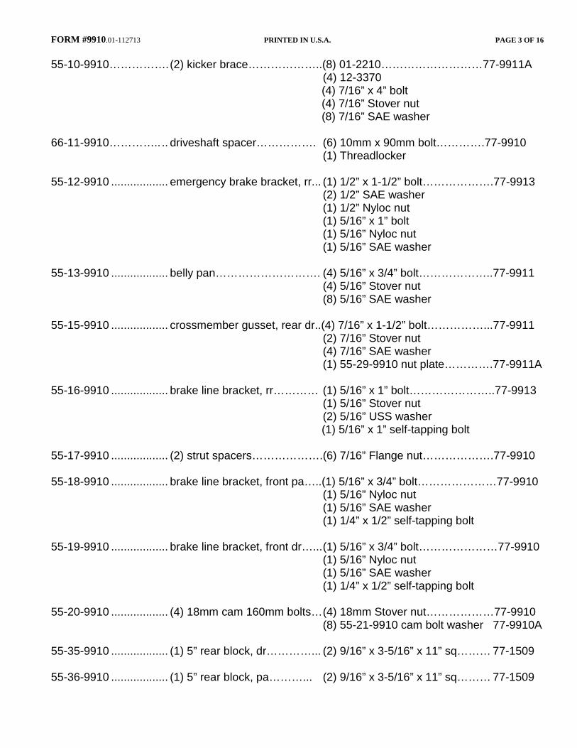
FORM #9910.01-112713 PRINTED IN U.S.A. PAGE 3 OF 16 55-10-9910……………. (2) kicker brace………………..(8) 01-2210………………………77-9911A
(4) 12-3370 (4) 7/16” x 4” bolt (4) 7/16” Stover nut (8) 7/16” SAE washer 66-11-9910………….. .. driveshaft spacer……………. (6) 10mm x 90mm bolt………….77-9910 (1) Threadlocker 55-12-9910 .................. emergency brake bracket, rr... (1) 1/2” x 1-1/2” bolt……………….77-9913 (2) 1/2” SAE washer (1) 1/2” Nyloc nut (1) 5/16” x 1” bolt (1) 5/16” Nyloc nut (1) 5/16” SAE washer 55-13-9910 .................. belly pan………………………. (4) 5/16” x 3/4” bolt………………..77-9911 (4) 5/16” Stover nut (8) 5/16” SAE washer 55-15-9910 .................. crossmember gusset, rear dr..(4) 7/16” x 1-1/2” bolt……………...77-9911 (2) 7/16” Stover nut (4) 7/16” SAE washer (1) 55-29-9910 nut plate………….77-9911A 55-16-9910 .................. brake line bracket, rr………… (1) 5/16” x 1” bolt…………………..77-9913 (1) 5/16” Stover nut (2) 5/16” USS washer (1) 5/16” x 1” self-tapping bolt 55-17-9910 .................. (2) strut spacers……………….(6) 7/16” Flange nut……………….77-9910 55-18-9910 .................. brake line bracket, front pa…..(1) 5/16” x 3/4” bolt…………………77-9910 (1) 5/16” Nyloc nut (1) 5/16” SAE washer (1) 1/4” x 1/2” self-tapping bolt 55-19-9910 .................. brake line bracket, front dr…... (1) 5/16” x 3/4” bolt…………………77-9910 (1) 5/16” Nyloc nut (1) 5/16” SAE washer (1) 1/4” x 1/2” self-tapping bolt 55-20-9910 .................. (4) 18mm cam 160mm bolts… (4) 18mm Stover nut………………77-9910 (8) 55-21-9910 cam bolt washer 77-9910A 55-35-9910 .................. (1) 5” rear block, dr…………... (2) 9/16” x 3-5/16” x 11” sq……… 77-1509 55-36-9910 .................. (1) 5” rear block, pa………... (2) 9/16” x 3-5/16” x 11” sq……… 77-1509

FORM #9910.01-112713 PRINTED IN U.S.A. PAGE 4 OF 16 (2) shock absorber, front (2) hardware pack and cable tie (2) shock absorber, rear (2) hardware pack and cable tie 00461........................... decal, "Warning To Driver"
KIT BOX BREAKDOWN 9910 / 9910B
1. 55-05-9910………………………………………………………………………… Qty. 1 2. 55-07-9910………………………………………………………………………… Qty. 1 3. 55-17-9910………………………………………………………………………… Qty. 2 4. 66-11-9910………………………………………………………………………… Qty. 1 5. 85160 or BE5-6250-H5…………………………………………………………… Qty. 2 6. 9914………………………………………………………………………………... Qty. 1
9911
1. 55-03-9910…………………………………………………………………………. Qty. 2 2. 55-04-9910…………………………………………………………………………. Qty. 1 3. 55-06-9910…………………………………………………………………………. Qty. 1 4. 55-09-9910…………………………………………………………………………. Qty. 2 5. 55-10-9910…………………………………………………………………………. Qty. 2 6. 55-13-9910…………………………………………………………………………. Qty. 1 7. 55-15-9910…………………………………………………………………………. Qty. 1 8. 9915……………………………………………………………………………...... Qty. 1
9912
1. 66-01-9910………………………………………………………………………… Qty. 1 2. 66-02-9910………………………………………………………………………… Qty. 1 3. 77-9912……………………………………………………………………………. Qty. 1
9913
1. 10362 (Ubolt)……………………………………………………………………… Qty. 4 2. 55-12-9910………………………………………………………………………… Qty. 1 3. 55-35--9910…………………………………………………………………………Qty. 1 4. 55-36-9910…………………………………………………………………………. Qty. 1 5. 9916……………………………………………………………………………… Qty. 1
9914
1. 77-9910……………………………………………………………………………. Qty. 1 2. 77-9910A………………………………………………………………………….. Qty. 1
9915
1. 77-9911……………………………………………………………………………. Qty. 1 2. 77-9911A………………………………………………………………………….. Qty. 1
9916
1. 77-1509……………………………………………………………………………. Qty. 1 2. 77-9913……………………………………………………………………………. Qty. 1 3. 77-9913A………………………………………………………………………….. Qty. 1
FORM #9910.01-112713 PRINTED IN U.S.A. PAGE 5 OF 16
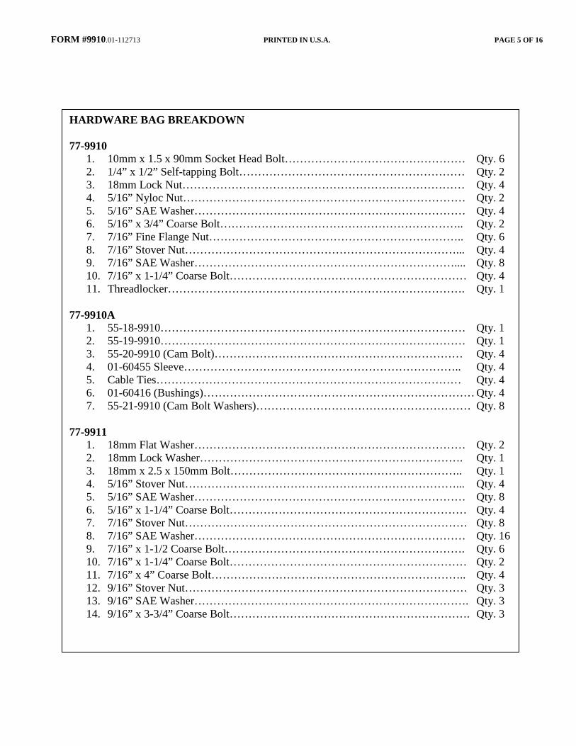
HARDWARE BAG BREAKDOWN 77-9910
1. 10mm x 1.5 x 90mm Socket Head Bolt………………………………………… Qty. 6 2. 1/4” x 1/2” Self-tapping Bolt …………………………………………………… Qty. 2 3. 18mm Lock Nut………………………………………………………………… Qty. 4 4. 5/16” Nyloc Nut………………………………………………………………… Qty. 2 5. 5/16” SAE Washer……………………………………………………………… Qty. 4 6. 5/16” x 3/4” Coarse Bolt……………………………………………………….. Qty. 2 7. 7/16” Fine Flange Nut………………………………………………………….. Qty. 6 8. 7/16” Stover Nut………………………………………………………………... Qty. 4 9. 7/16” SAE Washer…………………………………………………………….... Qty. 8 10. 7/16” x 1-1/4” Coarse Bolt……………………………………………………… Qty. 4 11. Threadlocker……………………………………………………………………. Qty. 1
77-9910A
1. 55-18-9910……………………………………………………………………… Qty. 1 2. 55-19-9910……………………………………………………………………… Qty. 1 3. 55-20-9910 (Cam Bolt)………………………………………………………… Qty. 4 4. 01-60455 Sleeve……………………………………………………………….. Qty. 4 5. Cable Ties……………………………………………………………………… Qty. 4 6. 01-60416 (Bushings)……………………………………………………………… Qty. 4 7. 55-21-9910 (Cam Bolt Washers)………………………………………………… Qty. 8
77-9911
1. 18mm Flat Washer……………………………………………………………… Qty. 2 2. 18mm Lock Washer……………………………………………………………. Qty. 1 3. 18mm x 2.5 x 150mm Bolt…………………………………………………….. Qty. 1 4. 5/16” Stover Nut………………………………………………………………... Qty. 4 5. 5/16” SAE Washer……………………………………………………………… Qty. 8 6. 5/16” x 1-1/4” Coarse Bolt……………………………………………………… Qty. 4 7. 7/16” Stover Nut………………………………………………………………… Qty. 8 8. 7/16” SAE Washer……………………………………………………………… Qty. 16 9. 7/16” x 1-1/2 Coarse Bolt………………………………………………………. Qty. 6 10. 7/16” x 1-1/4” Coarse Bolt……………………………………………………… Qty. 2 11. 7/16” x 4” Coarse Bolt………………………………………………………….. Qty. 4 12. 9/16” Stover Nut………………………………………………………………… Qty. 3 13. 9/16” SAE Washer………………………………………………………………. Qty. 3 14. 9/16” x 3-3/4” Coarse Bolt………………………………………………………. Qty. 3
FORM #9910.01-112713 PRINTED IN U.S.A. PAGE 6 OF 16
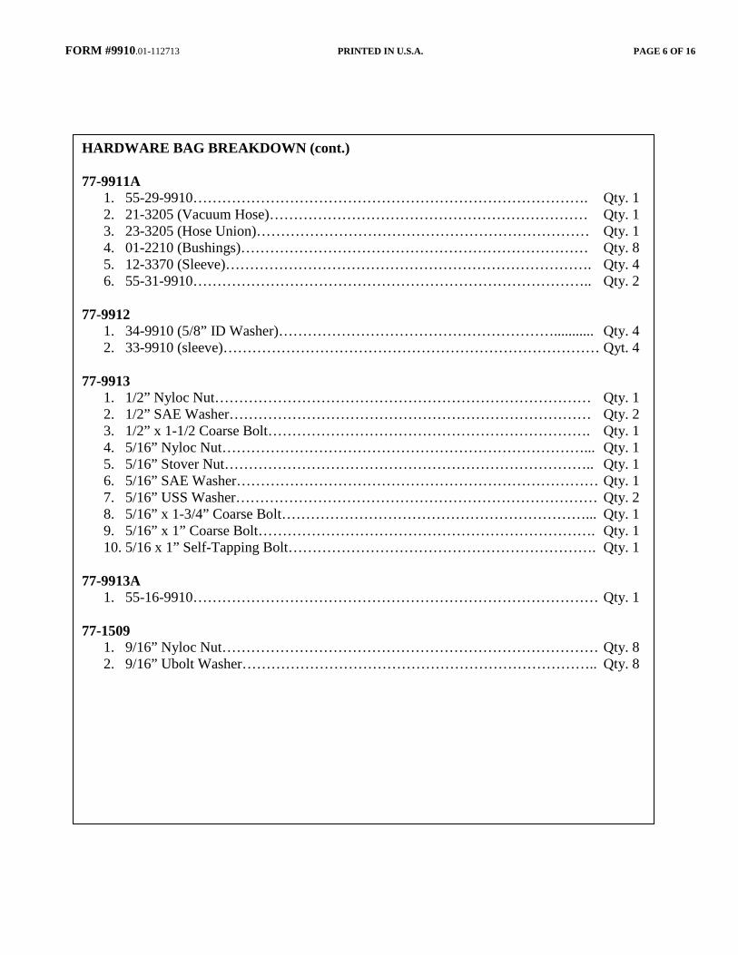
HARDWARE BAG BREAKDOWN (cont.) 77-9911A
1. 55-29-9910………………………………………………………………………. Qty. 1 2. 21-3205 (Vacuum Hose)………………………………………………………… Qty. 1 3. 23-3205 (Hose Union)…………………………………………………………… Qty. 1 4. 01-2210 (Bushings)……………………………………………………………… Qty. 8 5. 12-3370 (Sleeve)…………………………………………………………………. Qty. 4 6. 55-31-9910……………………………………………………………………….. Qty. 2
77-9912
1. 34-9910 (5/8” ID Washer)…………………………………………………........... Qty. 4 2. 33-9910 (sleeve)…………………………………………………………………… Qyt. 4
77-9913
1. 1/2” Nyloc Nut…………………………………………………………………… Qty. 1 2. 1/2” SAE Washer………………………………………………………………… Qty. 2 3. 1/2” x 1-1/2 Coarse Bolt…………………………………………………………. Qty. 1 4. 5/16” Nyloc Nut…………………………………………………………………... Qty. 1 5. 5/16” Stover Nut………………………………………………………………….. Qty. 1 6. 5/16” SAE Washer………………………………………………………………… Qty. 1 7. 5/16” USS Washer………………………………………………………………… Qty. 2 8. 5/16” x 1-3/4” Coarse Bolt………………………………………………………... Qty. 1 9. 5/16” x 1” Coarse Bolt……………………………………………………………. Qty. 1 10. 5/16 x 1” Self-Tapping Bolt………………………………………………………. Qty. 1
77-9913A
1. 55-16-9910………………………………………………………………………… Qty. 1 77-1509
1. 9/16” Nyloc Nut…………………………………………………………………… Qty. 8 2. 9/16” Ubolt Washer……………………………………………………………….. Qty. 8
FORM #9910.01-112713 PRINTED IN U.S.A. PAGE 7 OF 16 FRONT PROCEDURE
NOTE: Save all factory components and hardware for reuse, unless noted. 1) PREPARE VEHICLE...Place vehicle in neutral. Raise front of vehicle with a jack and secure a jack stand beneath each frame rail, behind the lower control arms. Ease the frame down onto the stands, place transmission in low gear or “park”, and chock rear tires. Remove front tires. 2) FRONT DIFFERENTIAL SKID PLATE AND DRIVESHAFT…If equipped, remove the factory front differential skid plate and discard. Mark the orientation of the front driveshaft, then disconnect from the differential, secure driveshaft up and out of the way. 3) ANTI-SWAY BAR LINKS…Disconnect the upper end of the anti-sway bar links from the sway bar body. Perform steps 4 through 8 one side at a time. 4) ABS AND VACUUM LINES…Remove the ABS wire, sensors, and vacuum lines from the back of the hub. 5) KNUCKLES… Remove the brake caliper from the rotor and secure it away from the work area. NOTE: Do not let calipers hang from brake lines. Remove the front rotor from the hub. Remove the retaining nut from the center of the bearing hub. Loosen, but do not remove, the upper control arm bolts. Using the appropriate puller tool, disconnect the upper and lower ball joints and outer tie rod end from the knuckle. Remove knuckle. 6) ANTI-SWAY BAR BODY...Mark the orientation of the sway bar body and then remove it from the vehicle. 7) STRUT… Mark the outside of the strut body for the reinstallation. Remove the three nuts from the top of the strut and the one lower bolt and nut. Remove the coil from the vehicle. 8) LOWER CONTROL ARM…Remove the lower control arm’s bolt (alignment cam bolts) assemblies then remove the lower control arm. Repeat steps 4 through 8 on remaining side. 9) REAR CROSSMEMBER…Remove the rear crossmember brace. 10) DIFFERENTIAL… Disconnect all electrical and vacuum lines from differential. Remove the rear differential bolt and loosen the two front bolts. Shift the differential to the passenger side to allow for clearance for the driver side bolt to clear the steering.
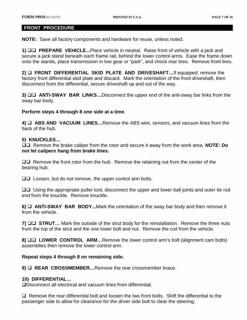
FORM #9910.01-112713 PRINTED IN U.S.A. PAGE 8 OF 16 Support the differential and remove all differential-to-frame bolts. Remove differential assembly. 11) TRIMMING LOWER CONTROL ARM MOUNT… [SEE PHOTO 1] The factory driver side rear lower control arm mount must be trimmed as shown. Start on the front side and measure up 3” from the top of the alignment cam bolt hole and mark. The rear differential mount will also need to be trimmed as shown. Cut the bracket along the marked lines using a cut-off wheel or Sawz-All. Mark the front side only of the passenger side lower control arm mount 1/4” from the bottom edge as shown. Cut the bracket along the marked line using a cut-off wheel or Sawz-All. Do not cut the rear of the passenger side lower control arm.
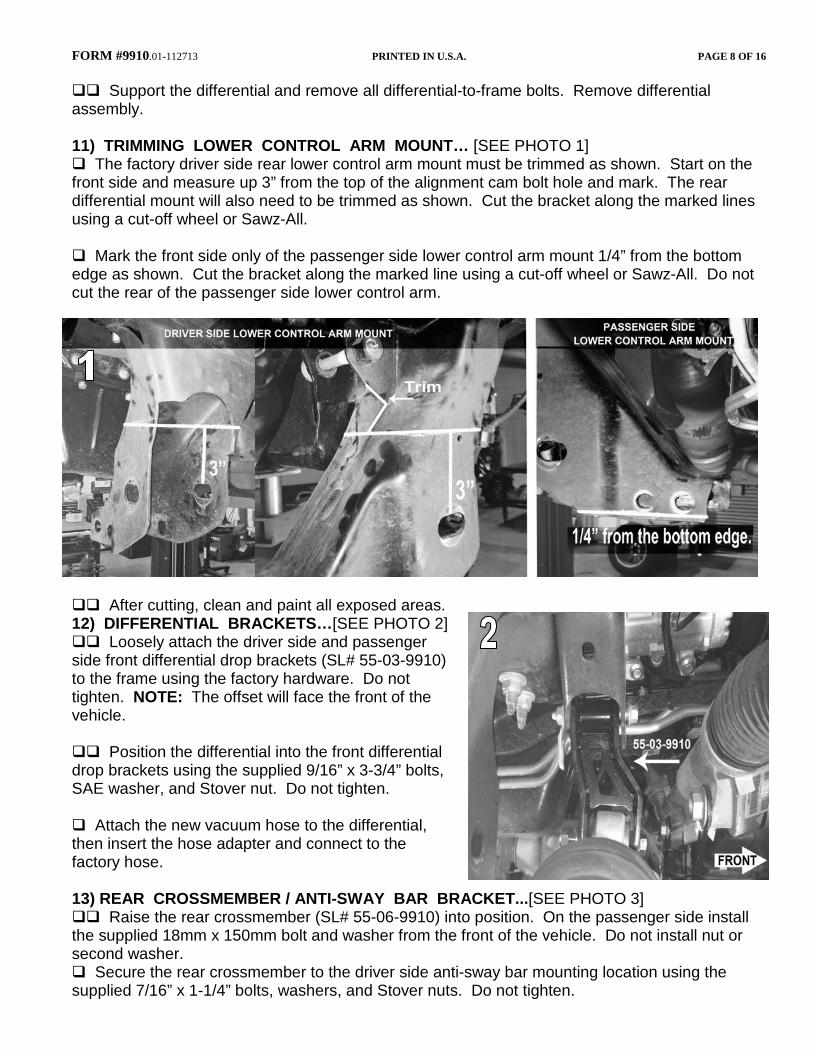
After cutting, clean and paint all exposed areas. 12) DIFFERENTIAL BRACKETS…[SEE PHOTO 2] Loosely attach the driver side and passenger side front differential drop brackets (SL# 55-03-9910) to the frame using the factory hardware. Do not tighten. NOTE: The offset will face the front of the vehicle. Position the differential into the front differential drop brackets using the supplied 9/16” x 3-3/4” bolts, SAE washer, and Stover nut. Do not tighten. Attach the new vacuum hose to the differential, then insert the hose adapter and connect to the factory hose. 13) REAR CROSSMEMBER / ANTI-SWAY BAR BRACKET...[SEE PHOTO 3] Raise the rear crossmember (SL# 55-06-9910) into position. On the passenger side install the supplied 18mm x 150mm bolt and washer from the front of the vehicle. Do not install nut or second washer. Secure the rear crossmember to the driver side anti-sway bar mounting location using the supplied 7/16” x 1-1/4” bolts, washers, and Stover nuts. Do not tighten.
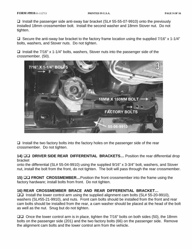
FORM #9910.01-112713 PRINTED IN U.S.A. PAGE 9 OF 16 Install the passenger side anti-sway bar bracket (SL# 55-55-07-9910) onto the previously installed 18mm crossmember bolt. Install the second washer and 18mm Stover nut. Do not tighten. Secure the anti-sway bar bracket to the factory frame location using the supplied 7/16” x 1-1/4” bolts, washers, and Stover nuts. Do not tighten. Install the 7/16” x 1-1/4” bolts, washers, Stover nuts into the passenger side of the crossmember. (50).
Install the two factory bolts into the factory holes on the passenger side of the rear crossmember. Do not tighten. 14) DRIVER SIDE REAR DIFFERENTIAL BRACKETS… Position the rear differential drop bracket onto the differential (SL# 55-04-9910) using the supplied 9/16” x 3-3/4” bolt, washers, and Stover nut, install the bolt from the front, do not tighten. The bolt will pass through the rear crossmember. 15) FRONT CROSSMEMBER…Position the front crossmember into the frame using the factory hardware; install bolts from front. Do not tighten. 16) REAR CROSSMEMBER BRACE AND REAR DIFFERENTIAL BRACKET… Install the lower control arm using the supplied alignment cam bolts (SL# 55-20-9910), washers (SL#55-21-9910), and nuts. Front cam bolts should be installed from the front and rear cam bolts should be installed from the rear, a cam washer should be placed at the head of the bolt as well as the nut. Snug but do not tighten. Once the lower control arm is in place, tighten the 7/16” bolts on both sides (50), the 18mm bolts on the passenger side (201) and the two factory bolts (66) on the passenger side. Remove the alignment cam bolts and the lower control arm from the vehicle.
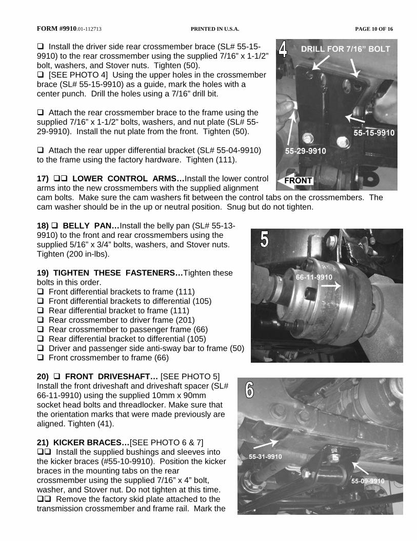
FORM #9910.01-112713 PRINTED IN U.S.A. PAGE 10 OF 16 Install the driver side rear crossmember brace (SL# 55-15-9910) to the rear crossmember using the supplied 7/16” x 1-1/2” bolt, washers, and Stover nuts. Tighten (50). [SEE PHOTO 4] Using the upper holes in the crossmember brace (SL# 55-15-9910) as a guide, mark the holes with a center punch. Drill the holes using a 7/16” drill bit. Attach the rear crossmember brace to the frame using the supplied 7/16” x 1-1/2” bolts, washers, and nut plate (SL# 55-29-9910). Install the nut plate from the front. Tighten (50). Attach the rear upper differential bracket (SL# 55-04-9910) to the frame using the factory hardware. Tighten (111). 17) LOWER CONTROL ARMS…Install the lower control arms into the new crossmembers with the supplied alignment cam bolts. Make sure the cam washers fit between the control tabs on the crossmembers. The cam washer should be in the up or neutral position. Snug but do not tighten. 18) BELLY PAN…Install the belly pan (SL# 55-13-9910) to the front and rear crossmembers using the supplied 5/16” x 3/4” bolts, washers, and Stover nuts. Tighten (200 in-lbs). 19) TIGHTEN THESE FASTENERS…Tighten these bolts in this order. Front differential brackets to frame (111) Front differential brackets to differential (105) Rear differential bracket to frame (111) Rear crossmember to driver frame (201) Rear crossmember to passenger frame (66) Rear differential bracket to differential (105) Driver and passenger side anti-sway bar to frame (50) Front crossmember to frame (66) 20) FRONT DRIVESHAFT… [SEE PHOTO 5] Install the front driveshaft and driveshaft spacer (SL# 66-11-9910) using the supplied 10mm x 90mm socket head bolts and threadlocker. Make sure that the orientation marks that were made previously are aligned. Tighten (41). 21) KICKER BRACES…[SEE PHOTO 6 & 7] Install the supplied bushings and sleeves into the kicker braces (#55-10-9910). Position the kicker braces in the mounting tabs on the rear crossmember using the supplied 7/16” x 4” bolt, washer, and Stover nut. Do not tighten at this time. Remove the factory skid plate attached to the transmission crossmember and frame rail. Mark the
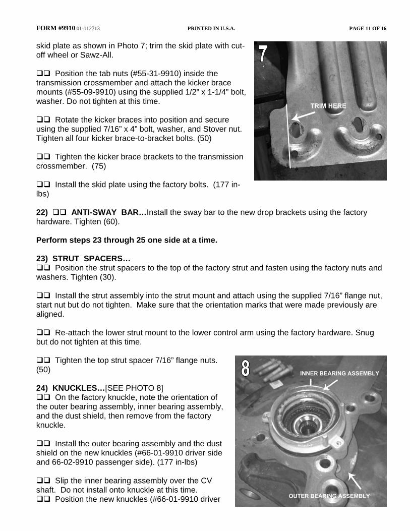
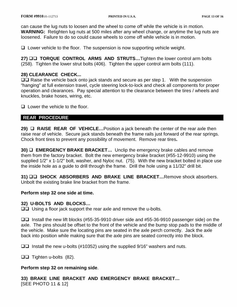
FORM #9910.01-112713 PRINTED IN U.S.A. PAGE 11 OF 16 skid plate as shown in Photo 7; trim the skid plate with cut-off wheel or Sawz-All. Position the tab nuts (#55-31-9910) inside the transmission crossmember and attach the kicker brace mounts (#55-09-9910) using the supplied 1/2” x 1-1/4” bolt, washer. Do not tighten at this time. Rotate the kicker braces into position and secure using the supplied 7/16” x 4” bolt, washer, and Stover nut. Tighten all four kicker brace-to-bracket bolts. (50) Tighten the kicker brace brackets to the transmission crossmember. (75) Install the skid plate using the factory bolts. (177 in-lbs) 22) ANTI-SWAY BAR…Install the sway bar to the new drop brackets using the factory hardware. Tighten (60). Perform steps 23 through 25 one side at a time. 23) STRUT SPACERS… Position the strut spacers to the top of the factory strut and fasten using the factory nuts and washers. Tighten (30). Install the strut assembly into the strut mount and attach using the supplied 7/16” flange nut, start nut but do not tighten. Make sure that the orientation marks that were made previously are aligned. Re-attach the lower strut mount to the lower control arm using the factory hardware. Snug but do not tighten at this time. Tighten the top strut spacer 7/16” flange nuts. (50) 24) KNUCKLES…[SEE PHOTO 8] On the factory knuckle, note the orientation of the outer bearing assembly, inner bearing assembly, and the dust shield, then remove from the factory knuckle. Install the outer bearing assembly and the dust shield on the new knuckles (#66-01-9910 driver side and 66-02-9910 passenger side). (177 in-lbs) Slip the inner bearing assembly over the CV shaft. Do not install onto knuckle at this time. Position the new knuckles (#66-01-9910 driver

FORM #9910.01-112713 PRINTED IN U.S.A. PAGE 12 OF 16 side and 66-02-9910 passenger side) on the lower control arm ball joint while sliding the CV shaft into the new knuckle. Install the factory nuts onto the lower control arm ball joint and the CV shaft. Tighten lower ball joint nut (111). Attach the upper ball joint to the knuckle and tighten. (85). Bolt the inner bearing assembly to the new knuckle. (133 in-lbs). Connect the ABS wiring, sensor, and vacuum lines to the hub. Install the rotors. Install the calipers onto the front rotors using the factory bolts. (136) NOTE: Starting in 2010 some vehicles will require the supplied 5/8” washers (#34-9910) to be installed under the head of the factory caliper bolts to keep the end of the bolt from contacting the brake rotor. ***VERY IMPORTANT FOR 2009 VEHICLES*** 2009 vehicles will require the use of the (#33-9910) sleeves to be installed in the mounting holes on the new knuckle. Attach the tie rod end to the knuckle. Tighten (136). Tighten the CV nut (20) and install dust cap. Connect the sway bar links to the sway bar body and tighten. (59). 25) BRAKE LINE BRACKETS…[SEE PHOTO 9] Remove the factory brake line bracket from the frame and install the new brake line brackets (#55-19-9910 driver side and 55-18-9910 passenger side) on the frame using the factory hardware. Use the bracket as a template to drill a 7/32” hole and install the 1/4” x 1” self-tapping bolt (75 in-lbs). Re-attach the factory brake line bracket to the new one using the supplied 5/16” x 3/4” bolt, washer, and Nyloc nut. (200 in-lbs.). Carefully bend brake lines to fit. Do not kink the lines. Perform step 23 through 25 on the remaining side. 26) TIRES / WHEELS...[SEE PHOTO 10] Install tires and wheels. Tighten the lug nuts in the sequence shown (150). WARNING: When the tires / wheels are installed, always check for and remove any corrosion, dirt, or foreign material on the wheel-mounting surface, or anything that contacts the wheel-mounting surface (hub, rotor, etc.). Installing wheels without the proper metal-to-metal contact at the wheel mounting surfaces
FORM #9910.01-112713 PRINTED IN U.S.A. PAGE 13 OF 16 can cause the lug nuts to loosen and the wheel to come off while the vehicle is in motion. WARNING: Retighten lug nuts at 500 miles after any wheel change, or anytime the lug nuts are loosened. Failure to do so could cause wheels to come off while vehicle is in motion. Lower vehicle to the floor. The suspension is now supporting vehicle weight. 27) TORQUE CONTROL ARMS AND STRUTS…Tighten the lower control arm bolts (258). Tighten the lower strut bolts (406). Tighten the upper control arm bolts (111). 28) CLEARANCE CHECK... Raise the vehicle back onto jack stands and secure as per step 1. With the suspension “hanging” at full extension travel, cycle steering lock-to-lock and check all components for proper operation and clearances. Pay special attention to the clearance between the tires / wheels and knuckles, brake hoses, wiring, etc. Lower the vehicle to the floor. REAR PROCEDURE
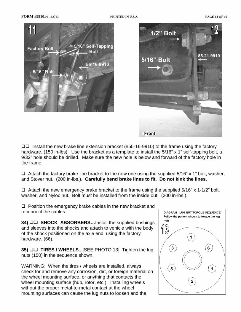
29) RAISE REAR OF VEHICLE…Position a jack beneath the center of the rear axle then raise rear of vehicle. Secure jack stands beneath the frame rails just forward of the rear springs. Chock front tires to prevent any possibility of movement. Remove rear tires. 30) EMERGENCY BRAKE BRACKET… Unclip the emergency brake cables and remove them from the factory bracket. Bolt the new emergency brake bracket (#55-12-9910) using the supplied 1/2” x 1-1/2” bolt, washer, and Nyloc nut. (75). With the new bracket bolted in place use the inside hole as a guide to drill through the frame. Drill the hole using a 11/32” drill bit. 31) SHOCK ABSORBERS AND BRAKE LINE BRACKET…Remove shock absorbers. Unbolt the existing brake line bracket from the frame. Perform step 32 one side at time. 32) U-BOLTS AND BLOCKS… Using a floor jack support the rear axle and remove the u-bolts. Install the new lift blocks (#55-35-9910 driver side and #55-36-9910 passenger side) on the axle. The pins should be offset to the front of the vehicle and the bump stop pads to the middle of the vehicle. Make sure the locating pins are seated in the axle perch correctly. Jack the axle back into position while making sure that the axle pins are seated correctly into the block. Install the new u-bolts (#10352) using the supplied 9/16” washers and nuts. Tighten u-bolts (82). Perform step 32 on remaining side. 33) BRAKE LINE BRACKET AND EMERGENCY BRAKE BRACKET… [SEE PHOTO 11 & 12]
FORM #9910.01-112713 PRINTED IN U.S.A. PAGE 14 OF 16
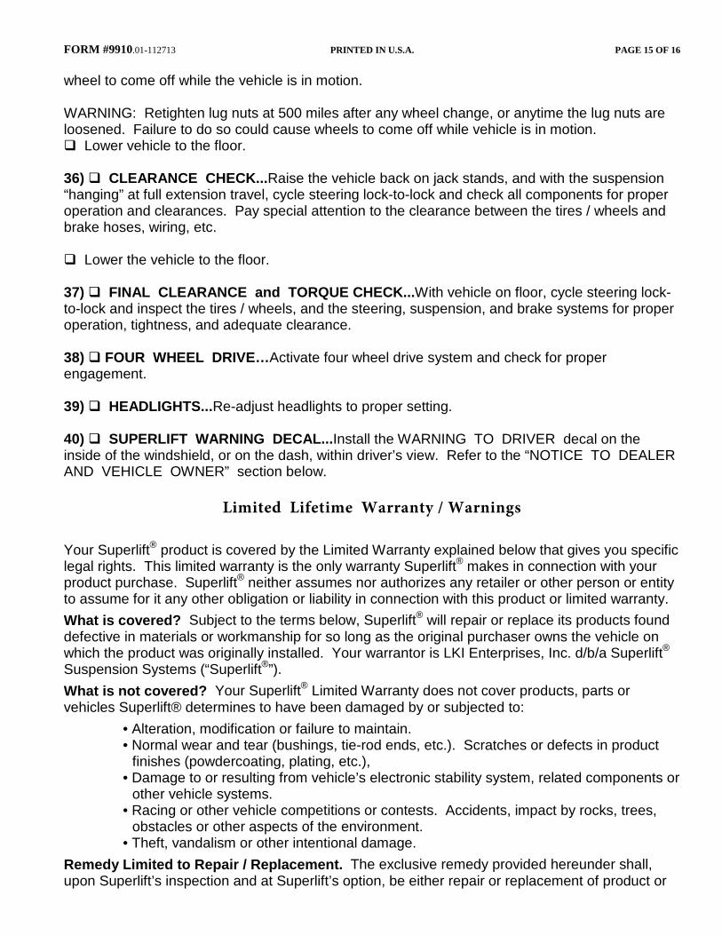
Install the new brake line extension bracket (#55-16-9910) to the frame using the factory hardware. (150 in-lbs). Use the bracket as a template to install the 5/16” x 1” self-tapping bolt, a 9/32” hole should be drilled. Make sure the new hole is below and forward of the factory hole in the frame. Attach the factory brake line bracket to the new one using the supplied 5/16” x 1” bolt, washer, and Stover nut. (200 in-lbs.). Carefully bend brake lines to fit. Do not kink the lines. Attach the new emergency brake bracket to the frame using the supplied 5/16” x 1-1/2” bolt, washer, and Nyloc nut. Bolt must be installed from the inside out. (200 in-lbs.). Position the emergency brake cables in the new bracket and reconnect the cables. 34) SHOCK ABSORBERS…Install the supplied bushings and sleeves into the shocks and attach to vehicle with the body of the shock positioned on the axle end, using the factory hardware. (66). 35) TIRES / WHEELS...[SEE PHOTO 13] Tighten the lug nuts (150) in the sequence shown. WARNING: When the tires / wheels are installed, always check for and remove any corrosion, dirt, or foreign material on the wheel mounting surface, or anything that contacts the wheel mounting surface (hub, rotor, etc.). Installing wheels without the proper metal-to-metal contact at the wheel mounting surfaces can cause the lug nuts to loosen and the
FORM #9910.01-112713 PRINTED IN U.S.A. PAGE 15 OF 16 wheel to come off while the vehicle is in motion. WARNING: Retighten lug nuts at 500 miles after any wheel change, or anytime the lug nuts are loosened. Failure to do so could cause wheels to come off while vehicle is in motion. Lower vehicle to the floor. 36) CLEARANCE CHECK...Raise the vehicle back on jack stands, and with the suspension “hanging” at full extension travel, cycle steering lock-to-lock and check all components for proper operation and clearances. Pay special attention to the clearance between the tires / wheels and brake hoses, wiring, etc. Lower the vehicle to the floor. 37) FINAL CLEARANCE and TORQUE CHECK...With vehicle on floor, cycle steering lock-to-lock and inspect the tires / wheels, and the steering, suspension, and brake systems for proper operation, tightness, and adequate clearance. 38) FOUR WHEEL DRIVE…Activate four wheel drive system and check for proper engagement. 39) HEADLIGHTS...Re-adjust headlights to proper setting. 40) SUPERLIFT WARNING DECAL...Install the WARNING TO DRIVER decal on the inside of the windshield, or on the dash, within driver’s view. Refer to the “NOTICE TO DEALER AND VEHICLE OWNER” section below.
Limited Lifetime Warranty / Warnings
Your Superlift® product is covered by the Limited Warranty explained below that gives you specific legal rights. This limited warranty is the only warranty Superlift® makes in connection with your product purchase. Superlift® neither assumes nor authorizes any retailer or other person or entity to assume for it any other obligation or liability in connection with this product or limited warranty. What is covered? Subject to the terms below, Superlift® will repair or replace its products found defective in materials or workmanship for so long as the original purchaser owns the vehicle on which the product was originally installed. Your warrantor is LKI Enterprises, Inc. d/b/a Superlift® Suspension Systems (“Superlift®”). What is not covered? Your Superlift® Limited Warranty does not cover products, parts or vehicles Superlift® determines to have been damaged by or subjected to:
• Alteration, modification or failure to maintain. • Normal wear and tear (bushings, tie-rod ends, etc.). Scratches or defects in product
finishes (powdercoating, plating, etc.), • Damage to or resulting from vehicle’s electronic stability system, related components or
other vehicle systems. • Racing or other vehicle competitions or contests. Accidents, impact by rocks, trees,
obstacles or other aspects of the environment. • Theft, vandalism or other intentional damage.
Remedy Limited to Repair / Replacement. The exclusive remedy provided hereunder shall, upon Superlift’s inspection and at Superlift’s option, be either repair or replacement of product or
FORM #9910.01-112713 PRINTED IN U.S.A. PAGE 16 OF 16 parts covered under this Limited Warranty. Customers requesting warranty consideration should contact Superlift® by phone (1-800-551-4955) to obtain a Returned Goods Authorization number. All removal, shipping and installation costs are customer’s responsibility. If a replacement part is needed before the Superlift® part in question can be returned, you must first purchase the replacement part. Then, if the part in question is deemed warrantable, you will be credited / refunded. Other Limitations - Exclusion of Damages - Your Rights Under State Law
• Neither Superlift® nor your independent Superlift® dealer are responsible for any time
loss, rental costs, or for any incidental, consequential or other damages you may have. • This Limited Warranty gives you specific rights. You may also have other rights that
vary from state to state. For example, while all implied warranties are disclaimed herein, any implied warranty required by law is limited to the terms of our Limited Lifetime Warranty as described above. Some states do not allow limitations of how long an implied warranty lasts and / or do not allow the exclusion or limitation of incidental or consequential damages, so the limitations and exclusions herein may not apply to you.
Important Product Use and Safety Information / Warnings As a general rule, the taller a vehicle is, the easier it will roll over. Offset, as much as possible, what is lost in rollover resistance by increasing tire track width. In other words, go “wide” as you go “tall”. Many sportsmen remove their mud tires after hunting season and install ones more appropriate for street driving; always use as wide a tire and wheel combination as feasible to enhance vehicle stability. We strongly recommend, because of rollover possibility, that the vehicle be equipped with a functional roll bar and cage system. Seat belts and shoulder harnesses should be worn at all times. Avoid situations where a side rollover may occur. Generally, braking performance and capabilities are decreased when significantly larger / heavier tires and wheels are used. Take this into consideration while driving. Also, changing axle gear ratios or using tires that are taller or shorter than factory height will cause an erroneous speedometer reading. On vehicles equipped with an electronic speedometer, the speed signal impacts other important functions as well. Speedometer recalibration for both mechanical and electronic types is highly recommended. Do not add, alter, or fabricate any factory or aftermarket parts to increase vehicle height over the intended height of the Superlift product purchased. Mixing component brands is not recommended. All Superlift® material is copyrighted. All images found in this catalog and in any Superlift® marketing forums are the sole property of or licensed to Superlift®. Any reproduction of said materials, in part or in whole, with out the express written permission of Superlift® is strictly forbidden. Superlift®, Rockrunner™, Swamprunner™, Superide™, Superide SS™ and SSR™, Black Diamond®, XCL™, X2™ Super Trac™, Torque Max™, Torque Max SS™, eXtreme Ring™, Rail Wrap™, Bullet Proof Brake Hose™, TruSpeed™, Frame Integrated Technology™, F.I.T. Series™ and Rock Fink™ are registered trademarks of Superlift® Suspension Systems. Superlift® Suspension Systems is a Division of Bret Lovett’s Lift Kits Incorporated.
SUPERLIFT SUSPENSION SYSTEMS 300 Huey Lenard Loop Rd.
West Monroe, Louisiana 71292 Phone: (318) 397-3000
Sales / Tech: 1-800-551-4955 FAX: (318) 397-3040 www.superlift.com