Embed Size (px)
Citation preview

Super ZX 30 & ZX 30 3F
USER MANUAL24378-01A

24378-01A
i
Limited Lifetime Warranty
SunStar® warrants your tanning unit to be free of structural defects in its material andworkmanship, under normal use, for its lifetime. SunStar will repair or replace, at their dis-
cretion, any defect to the structure which affects the performance of the unit.
For 6 months from the date of purchase, SunStar will provide replacements for parts thatprove to be defective in material or workmanship. Acrylic shields, fluorescent lamps, and
lamp starters are excluded from this warranty. Labor will be covered for 30 days from pur-chase date. Normal wear, damage from misuse or abuse, damage incurred in transit, or
damage done by unauthorized repairs or modifications are not covered by this warranty.
ETS, Inc. disclaims any implied warranty of merchantability or fitness for any periodbeyond the expressed warranty. Some states do not allow limitations on how long an
implied warranty lasts, so the above limitations may not apply to you.
No one has authority to change or modify this Limited Lifetime Warranty in any respect. Toobtain service under the Limited Lifetime Warranty, contact ETS, Inc. at 1-800-449-3605,
and ask for the Technical Service Department.
ETS, Inc. shall not be liable for loss of use, loss of time , inconvenience, rental or substituteproducts, loss of business, loss of income, or any other incidental or consequential damages.Some states do not allow the exclusion or limitation of incidental or consequential damages,
so the above limitation or exclusion may not apply to you.
This warranty gives you specific legal rights, and you may also have other rights which mayvary from state to state.
All warranty service must be performed by an authorized service person. If your tanningunit must be returned for service, all freight charges must be at your expense. Contact yourplace of purchase for the address of the SunStar Service Center nearest you. Proof of pur-
chase is required to obtain warranty service.
This warranty covers the original purchaser only. This warranty is void if the unit is modi-fied in any manner from its original design.
2437
8-01
A ii
elcomeCongratulations on your purchase of this technologically advanced sun tanning unit. It has beendesigned to provide years of dependable service for you.
Please read all the instructions in this booklet before installing and using the unit. Always be sure toobserve all safety precautions.
ontentsSafety Information . . . . . . . . . . . . . . . . . . . . . . . . . . . . . . . . . . . . . . . .iii
Installation . . . . . . . . . . . . . . . . . . . . . . . . . . . . . . . . . . . . . . . . . . . . . .1Unpacking and Inspection . . . . . . . . . . . . . . . . . . . . . . . . . . . . . .1Pre-Installation Planning . . . . . . . . . . . . . . . . . . . . . . . . . . . . . . .2Tools Required . . . . . . . . . . . . . . . . . . . . . . . . . . . . . . . . . . . . . .3Hardware Inventory . . . . . . . . . . . . . . . . . . . . . . . . . . . . . . . . . . .4Assembly Procedures . . . . . . . . . . . . . . . . . . . . . . . . . . . . . . . . . .6Electrical Connections . . . . . . . . . . . . . . . . . . . . . . . . . . . . . . . .18Remote Connections . . . . . . . . . . . . . . . . . . . . . . . . . . . . . . . . .19
Operation . . . . . . . . . . . . . . . . . . . . . . . . . . . . . . . . . . . . . . . . . . . . .22Before You Tan . . . . . . . . . . . . . . . . . . . . . . . . . . . . . . . . . . . . . .22Exposure Times . . . . . . . . . . . . . . . . . . . . . . . . . . . . . . . . . . . . .22Using Your Sunbed . . . . . . . . . . . . . . . . . . . . . . . . . . . . . . . . . .23
Care and Maintenance . . . . . . . . . . . . . . . . . . . . . . . . . . . . . . . . . . . .25Cleaning After Use . . . . . . . . . . . . . . . . . . . . . . . . . . . . . . . . . . .25Thorough Periodic Cleaning . . . . . . . . . . . . . . . . . . . . . . . . . . . .25Mechanical Inspection . . . . . . . . . . . . . . . . . . . . . . . . . . . . . . . .25Lamp and Acrylic Replacement . . . . . . . . . . . . . . . . . . . . . . . . .26
Troubleshooting . . . . . . . . . . . . . . . . . . . . . . . . . . . . . . . . . . . . . . . . .29

24378-01A
iii
afety Information
Ultraviolet radiation. Follow instructions. Avoid overexposure. As with natural sunlight, overexposure cancause eye and skin injury and allergic reactions. Repeated exposure may cause premature aging of the skin
and skin cancer. WEAR PROTECTIVE EYEWEAR; FAILURE TO MAY RESULT IN SEVERE BURNS OR LONGTERM INJURY TO THEEYES. Medications or cosmetics may increase your sensitivity to the ultraviolet radiation. Consult physician before using sunlamp ifyou are using medications or have a history of skin problems or believe yourself especially sensitive to sunlight. If you do not tan inthe sun, you are unlikely to tan from the use of this product. Children, the elderly, or fair skinned people who always burn easily andeither never tan or tan minimally should not use this equipment.
To use, lie down under canopy and pull down as far as adjustment will allow. Minimum use distance from face tanner (if equipped) is 4inches (10.2 centimeters). Minimum use distance elsewhere is touching the clear plastic panels. Do not use without clear plastic panels inplace. Untanned persons should not tan on consecutive days during their first week of tanning. Never tan more than once a day. Tanningnormally appears after the first few sessions and maximizes after approximately four weeks. Tan once or twice per week thereafter to main-tain appearance. Persons already having a base tan may begin at advanced levels corresponding to the extent of their base tan.
New lamps emit approximately 10% more ultraviolet radiation during the first 50 hours of operation. Recommended tanning timesshould therefore be reduced by approximately 10% during that period.
WARNING: • Read the instructions booklet before using this sunlamp product. • All persons in the room should wear protectiveeyewear when lamps are on. Recommended eyewear: provided eyeshields or equivalent eyewear as defined under 21 CFR 1040.20.Other types of eyewear may not provide adequate protection. Failure to use protective eyewear may result in severe burns or othereye injury. If discomfort develops, discontinue use and consult a physician.
ONLY THE FOLLOWING LAMPS HAVE BEEN CERTIFIED FOR USE IN THIS EQUIPMENT:SPEED® 175 Wolff® Model SPD75-T12 PREHEAT BIPIN (Bench lamps)
SPEED® 205 Wolff® Model SPD71-T12-205 BIPIN (Canopy lamps)
Heraeus E400 HPT, Philips Model HPA 400/30s or CosmoTech Model 23045 (SolarMax™ IFT facial unit : ZX30 3F)
THIS EQUIPMENT MUST BE EARTH GROUNDED.
This product is in conformity with performance standards for sun lamp products under 21 CFR PART 1040.20 andANSI/UL Standard 482. Certified to CAN/CSA Standard C22.2 NO. 224.
LABELING NOTICE: Labels are affixed on all systems to inform the user of possible dangers. Regulations are stated in 21 CFR, Section1040.20, and require that all products manufactured after September 8, 1986 which use sunlamps must display the following:
DANGER
RECOMMENDED EXPOSURE TIMES IN MINUTES MAXIMUM EXPOSURE TIME IS 20 MINUTESLevel 1/Week 1 Level 2 Level 3 Level 4 Subsequent
Skin Type: 1st-3rd Sessions MaximumI Sensitive Skin (Burns easily and severely and does not tan.) NOT RECOMMENDED FOR TANNINGII Light (Burns easily and severely and tans minimally.) 4 8 12 16 20III Normal (Burns moderately and tans average.) 6 10 15 20 20IV Dark (Burns minimally, tans easily and above average.) 8 12 16 20 20
DISCONNECT POWER CORD BEFORE ATTEMPTING TO CLEAN, RELAMP, OR ENGAGE IN THE MAINTENANCE OF THIS PRODUCT.
88465

2437
8-01
A iv
Safety Information
Rayonnement ultraviolet. Veuillez suivre les instructions. Évitez une exposition excessive. Tout comme pourles rayons du soleil, une exposition excessive peut causer des blessures aux yeux et à la peau et provoquer des
réactions allergiques. Une exposition répétée peut causer le vieillissement prématuré de la peau et provoquer le cancer de la peau.PORTEZ DES LUNETTES PROTECTRICES: LE NON-RESPECT DE CETTE CONSIGNE DE SÉCURITÉ PEUT ENTRAÎNER DE GRAVESBRÛLURES OU DES LÉSIONS OCULAIRES À LONG TERME. Les médicaments ou les produits cosmétiques peuvent augmenter votresensibilité au rayonnement ultraviolet. Consultez un médecin avant d’utiliser la lampe solaire si vous prenez des médicaments, si voussouffrez d’une maladie cutanée ou si vous croyez être particulièrement sensible aux rayons du soleil. Si vous ne bronzez pas au soleil,il est peu probable que vous bronzerez sous une lampe solaire. Les enfants, les personnes âgées et les personnes qui ont une peauclaire qui brûle facilement, ne bronze jamais ou alors très peu, ne devraient pas utiliser cette lampe.
Étendez-vous sous la partie supérieure, puis abaissez celle-ci aussi bas que possible. La distance minimale d’usage de l’appareil de bron-zage pour le visage (s’il y en a un) est de 4 pouces (10.2 centimètres). Les autres parties du corps peuvent toucher les panneaux de plas-tique transparents. N’utilisez pas la lampe sans les panneaux de plastique transparents. La première semaine de bronzage, les personnesqui n’ont pas un hâle initial ne doivent pas se faire bronzer tous les jours. Ne vous faites jamais bronzer plus d’une fois par jour. Le bron-zage commence normalement à apparaître après les premières séances : il atteint son apogée au bout d’environ quatre semaines. Lespersonnes qui ont déjà un teint hâlé peuvent commencer à des niveaux plus élevés, selon l’importance de leur hâle initial.
Les lampes neuves émettent approximativement 10 % de plus de rayons ultraviolets au cours des 50 premières heures de fonction-nement. Le temps de bronzage doit donc êatre réduit d\rquote environ 10 % pendant cette période.
AVERTISSEMENT : • Lisez le livret d’instructions avant d’utiliser cette lampe solaire. • Les autres personnes présentes dans la piècedoivent aussi porter des lunettes protectrices lorsque les lampes sont allumées. Coquilles de protection pour les yeux recommandées:Les coquilles de protection fournies ou l’équivalent, tel que le stipule le document 21 CFR 1040.20. Les autres types de lunettes protec-trices peuvent ne pas assurer une protection adéquate. Utilisé sans lunettes protectrices, ce produit peut causer des brûlures ou lésionsoculaires graves. Si vous souffrez d’un malaise, arrêtez l’utilisation et consultez un médecin.
SEULES LES LAMPES SUIVANTES ONT ÉTÉ HOMOLOGUÉES POUR CET ÉQUIPEMENT :SPEED® 175 Wolff® Modèle SPD75-T12 PREHEAT BIPIN (banc seulement)SPEED® 205 Wolff® Modèle SPD71-T12-205 BIPIN (partie supérieure seulement)Heraeus E400 HPT, Philips Modèle HPA 400/30s ou CosmoTech Modèle 23045 (unité faciale : ZX30 3F)
Cet équipement doit être mis à la terre.Ce produit est conforme aux normes de rendement pour les lampes solaires dans le documents 21 CFR, partie1040.20 , ANSI/UL 482 , CAN/CSA C22.2 N° 224.
DANGER
TEMPS D’EXPOSITION RECOMMANDÉ EN MINUTES LE TEMPS D’EXPOSITION MAXIMAL EST DE 20 MINUTESÉlevé 1/Semaine 1 Élevé 2 Élevé 3 Élevé 4 Sem. suivantes
Type de peau: 1ere-3e Temps maximal
I Peau sensible (brûle facilement et ne bronze pas) NON RECOMMANDÉ
II Peau claire (brûle facilement et bronze très peu) 4 8 12 16 20
III Peau normale (brûle et bronze de façon modérée) 6 10 15 20 20
IV Peau foncée (brûle très peu, bronze plus facilement que la moyenne) 8 12 16 20 20
Débranchez le cordon d’alimentation avant de nettoyer l’appareil, d’en faire l’entretien ou de changer les lampes.
88465

24378-01A
1
nstallation
Unpacking and Inspection
Your sunbed comes in two cardboard car-tons, one for the bench and one for thecanopy. Open the cartons and remove thebench and canopy as follows.
The bench and canopy are each wrappedin plastic. Pull back the plastic and, witha helper, grasp the bench and pull it fromthe carton bottom, leaving the plasticwrap and the carton packaging. Do thesame for the canopy. Do not attempt tolift either unit with the plastic still on asit may slip.
Note! The cartons are reusable, in theunlikely event that you may find it neces-sary to return your sunbed.
As you unpack your boxes you shouldfind the following:
• Canopy unit• Bench unit• Pair of gas springs• Box containing front and side skirts• Bag containing necessary assembly
hardware, safety goggles, openinghandle and pillow
• Box containing two stand legs, twocross member supports and four skirtmounting brackets
• Gas spring cover
Inspect these items, including the canopyand bench, and make sure they are freefrom any visible damage. Report theextent of any damage to the transportationcompany.
Record the serial numbers of the canopyand bench in the area provided at theback of this manual. This information willbe required whenever you call customerservice.
2437
8-01
A 2
Installation - Pre-Installation Planning
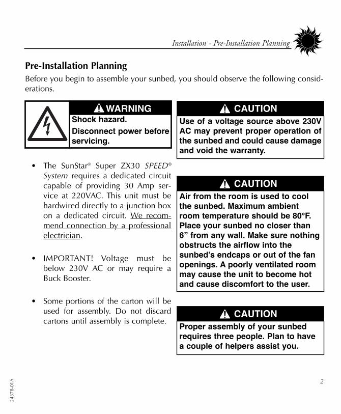
Pre-Installation PlanningBefore you begin to assemble your sunbed, you should observe the following consid-erations.
• The SunStar® Super ZX30 SPEED®System requires a dedicated circuitcapable of providing 30 Amp ser-vice at 220VAC. This unit must behardwired directly to a junction boxon a dedicated circuit. We recom-mend connection by a professionalelectrician.
• IMPORTANT! Voltage must bebelow 230V AC or may require aBuck Booster.
• Some portions of the carton will beused for assembly. Do not discardcartons until assembly is complete.
WARNINGShock hazard.Disconnect power beforeservicing.
Air from the room is used to coolthe sunbed. Maximum ambientroom temperature should be 80°F.Place your sunbed no closer than6” from any wall. Make sure nothingobstructs the airflow into thesunbed’s endcaps or out of the fanopenings. A poorly ventilated roommay cause the unit to become hotand cause discomfort to the user.
CAUTION
Use of a voltage source above 230VAC may prevent proper operation ofthe sunbed and could cause damageand void the warranty.
CAUTION
Proper assembly of your sunbedrequires three people. Plan to havea couple of helpers assist you.
CAUTION
24378-01A
3
Installation - Tools Required
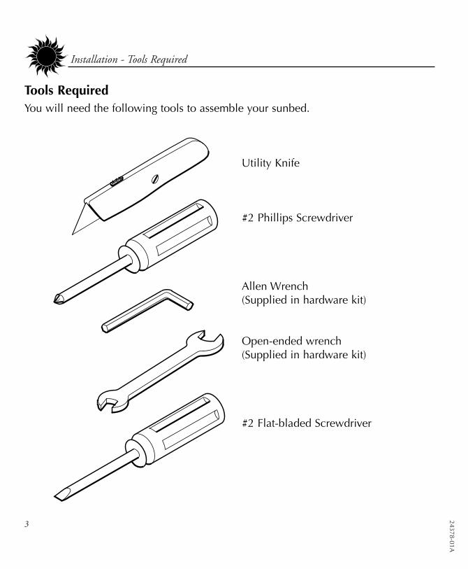
Tools RequiredYou will need the following tools to assemble your sunbed.
Utility Knife
#2 Phillips Screwdriver
Allen Wrench(Supplied in hardware kit)
Open-ended wrench(Supplied in hardware kit)
#2 Flat-bladed Screwdriver

2437
8-01
A 4
Installation - Hardware Inventory
Carriage Bolt,M10 x 60mm
Quantity 2
Self-locking Nut, M10Quantity 2
Hex SocketHead Bolt,
M8 x 80mmQuantity 4
Hex SocketHead Bolt,
M8 x 60mmQuantity 2
Self-locking Nut, M8Quantity 2
Plastic Trim CapQuantity 4
Hardware Inventory
Use the utility knife to cut open the hard-ware bag and blister pack. Remove thehardware. Make sure you have the follow-ing hardware items.
Hex Socket HeadBolt, M8 x 20mm
Quantity 8
Flat Washer, M8Quantity 12
Foot CapsQuantity 4
Clevis Fork,M10 LongQuantity 4
Plastic Spacer, 15mmQuantity 4
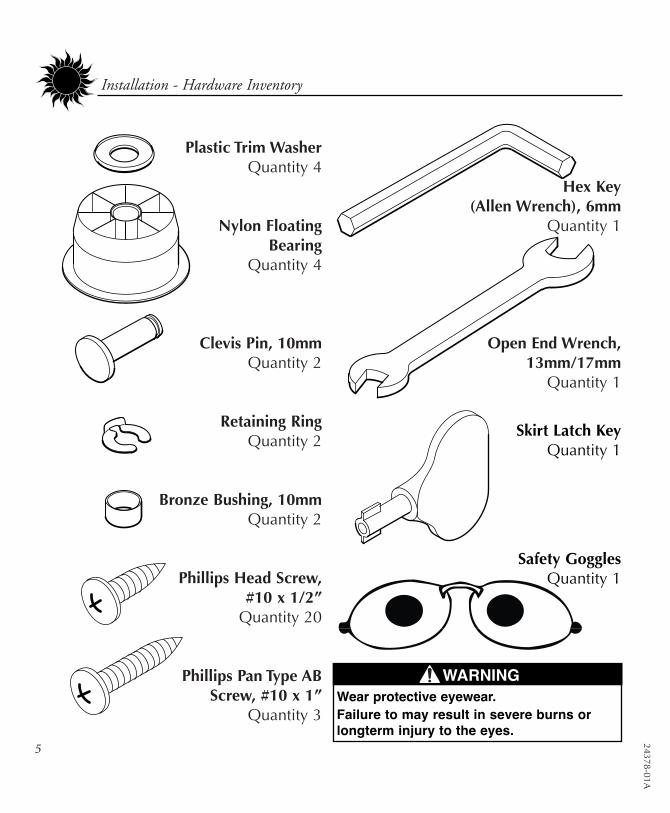
Hex Key (Allen Wrench), 6mm
Quantity 1
Open End Wrench, 13mm/17mm
Quantity 1
Plastic Trim WasherQuantity 4
Nylon FloatingBearing
Quantity 4
Clevis Pin, 10mmQuantity 2
Retaining RingQuantity 2
Bronze Bushing, 10mmQuantity 2
Phillips Head Screw,#10 x 1/2”
Quantity 20
Phillips Pan Type AB Screw, #10 x 1”
Quantity 3
24378-01A
5
Installation - Hardware Inventory
Skirt Latch KeyQuantity 1
Safety GogglesQuantity 1
WARNINGWear protective eyewear.Failure to may result in severe burns orlongterm injury to the eyes.

2437
8-01
A 6
Installation - Assembly Procedures
Assembly Procedures
Stand Assembly1. Fit the cross member supports (A) to
the stand legs (B) using the M8 x20mm bolts (C) and the M8 washers(D). Assemble the bolts a few turnsonly.
2. After the stand is assembled, tightenall bolts.
Tip: The rectangular hole on the outside ofthe stand leg channel is for Allen wrenchaccess. Insert the Allen wrench into theoutside rectangular hole. Next slide thewasher onto the bolt and the bolt onto theAllen wrench inside the stand channel.
24378-01A
7
Installation - Assembly Procedures
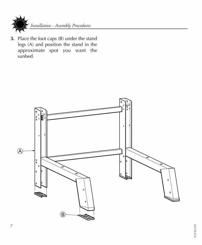
3. Place the foot caps (B) under the standlegs (A) and position the stand in theapproximate spot you want thesunbed.

2437
8-01
A 8
Installation - Assembly Procedures
4. Attach the four skirt mounting bracketsto each corner of the stand legs, usingeight #10 x 1/2” Phillips head screws.Each location is predrilled to accept abracket. You will notice that there aretwo types of brackets. The rear brack-ets are simply “L” shaped, while thefront brackets have a rectangular holeand a slight step.
24378-01A
9
Installation - Assembly Procedures
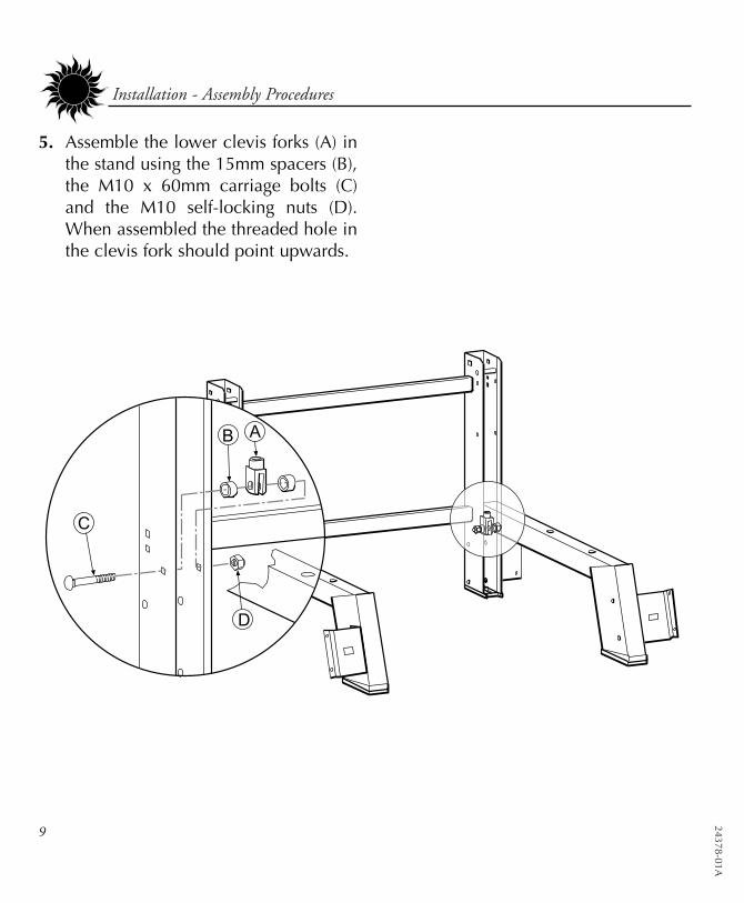
5. Assemble the lower clevis forks (A) inthe stand using the 15mm spacers (B),the M10 x 60mm carriage bolts (C)and the M10 self-locking nuts (D).When assembled the threaded hole inthe clevis fork should point upwards.
2437
8-01
A 10
Installation - Assembly Procedures
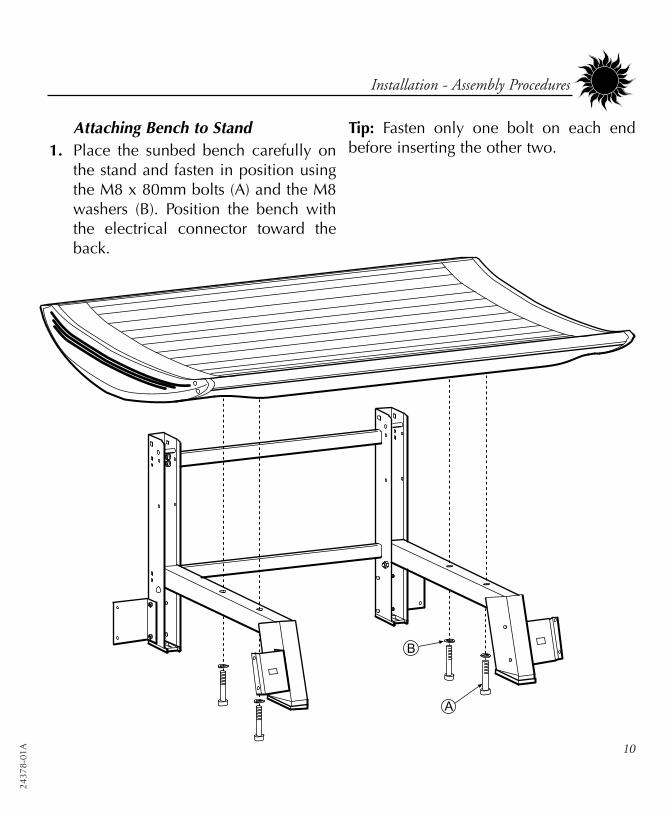
Attaching Bench to Stand1. Place the sunbed bench carefully on
the stand and fasten in position usingthe M8 x 80mm bolts (A) and the M8washers (B). Position the bench withthe electrical connector toward theback.
Tip: Fasten only one bolt on each endbefore inserting the other two.
24378-01A
11
Installation - Assembly Procedures
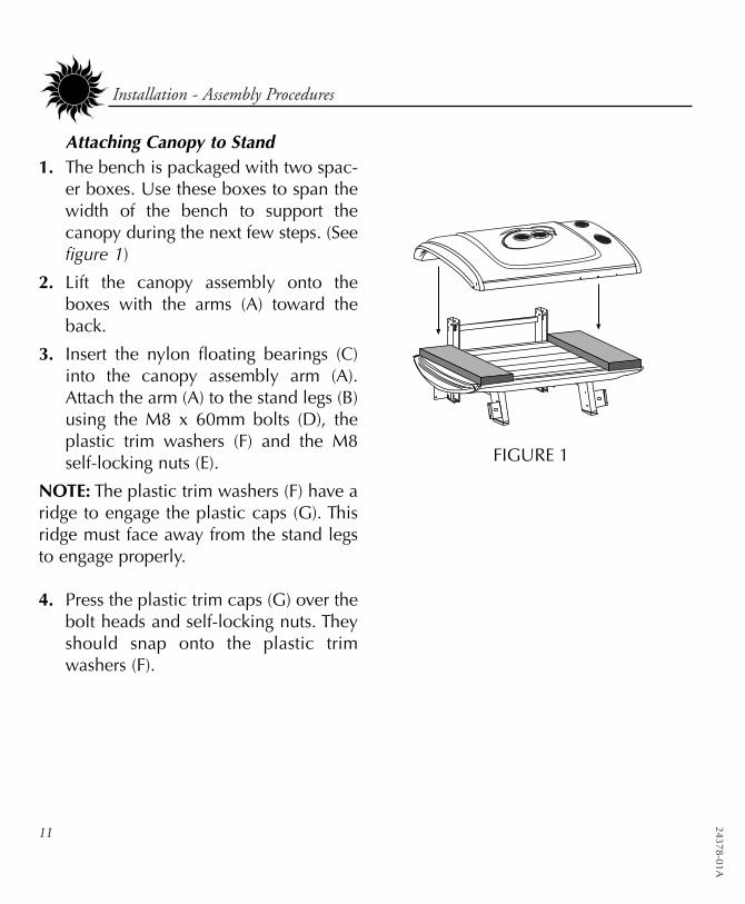
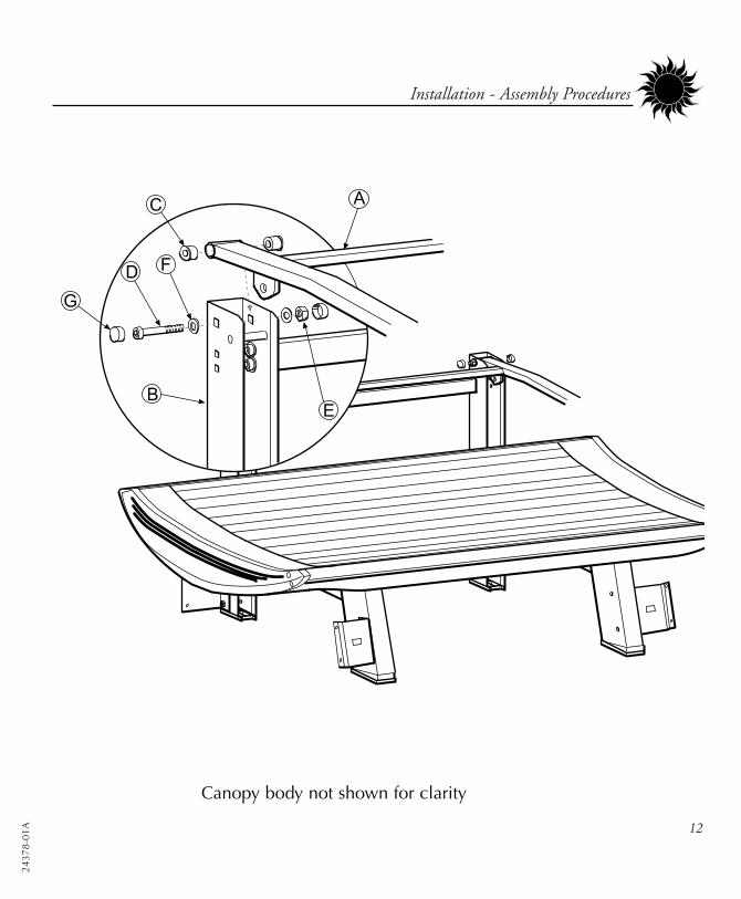
Attaching Canopy to Stand1. The bench is packaged with two spac-
er boxes. Use these boxes to span thewidth of the bench to support thecanopy during the next few steps. (Seefigure 1)
2. Lift the canopy assembly onto theboxes with the arms (A) toward theback.
3. Insert the nylon floating bearings (C)into the canopy assembly arm (A).Attach the arm (A) to the stand legs (B)using the M8 x 60mm bolts (D), theplastic trim washers (F) and the M8self-locking nuts (E).
NOTE: The plastic trim washers (F) have aridge to engage the plastic caps (G). Thisridge must face away from the stand legsto engage properly.
4. Press the plastic trim caps (G) over thebolt heads and self-locking nuts. Theyshould snap onto the plastic trimwashers (F).
FIGURE 1
2437
8-01
A 12
Installation - Assembly Procedures
Canopy body not shown for clarity
24378-01A
13
Installation - Assembly Procedures
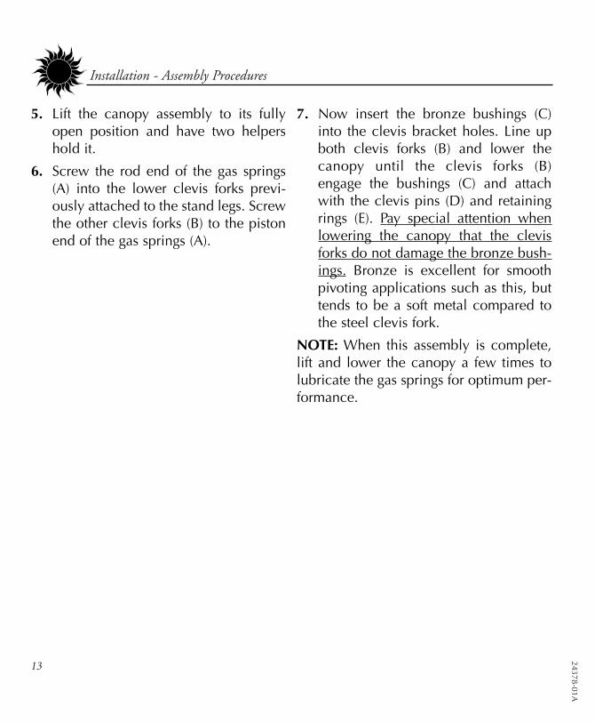
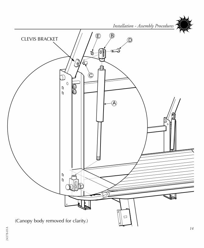
5. Lift the canopy assembly to its fullyopen position and have two helpershold it.
6. Screw the rod end of the gas springs(A) into the lower clevis forks previ-ously attached to the stand legs. Screwthe other clevis forks (B) to the pistonend of the gas springs (A).
7. Now insert the bronze bushings (C)into the clevis bracket holes. Line upboth clevis forks (B) and lower thecanopy until the clevis forks (B)engage the bushings (C) and attachwith the clevis pins (D) and retainingrings (E). Pay special attention whenlowering the canopy that the clevisforks do not damage the bronze bush-ings. Bronze is excellent for smoothpivoting applications such as this, buttends to be a soft metal compared tothe steel clevis fork.
NOTE: When this assembly is complete,lift and lower the canopy a few times tolubricate the gas springs for optimum per-formance.
2437
8-01
A 14
Installation - Assembly Procedures
CLEVIS BRACKET
(Canopy body removed for clarity.)
24378-01A
15
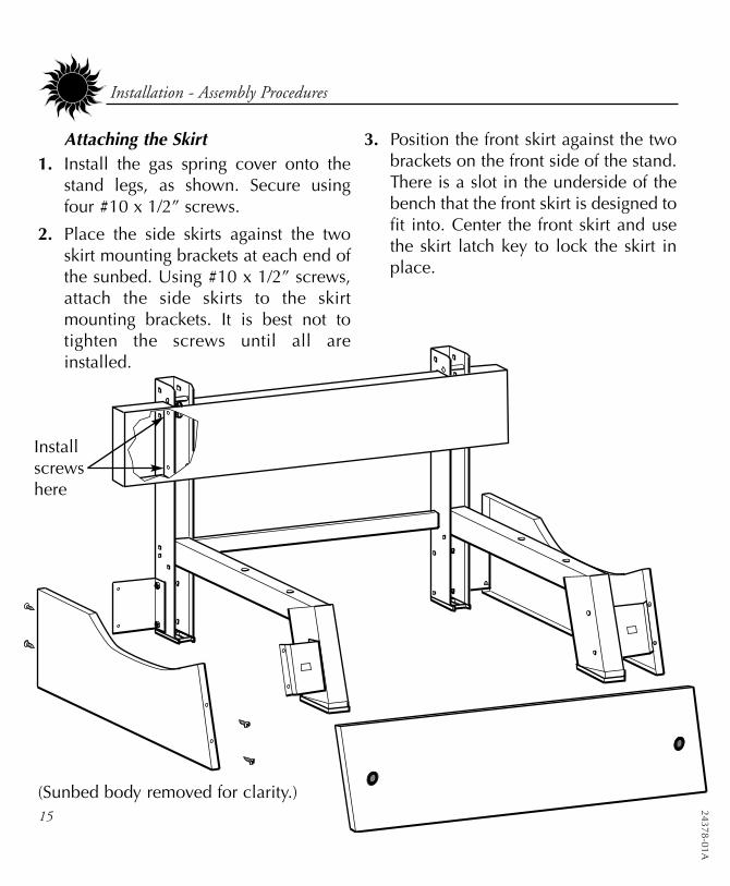
Installation - Assembly Procedures
Attaching the Skirt1. Install the gas spring cover onto the
stand legs, as shown. Secure usingfour #10 x 1/2” screws.
2. Place the side skirts against the twoskirt mounting brackets at each end ofthe sunbed. Using #10 x 1/2” screws,attach the side skirts to the skirtmounting brackets. It is best not totighten the screws until all areinstalled.
3. Position the front skirt against the twobrackets on the front side of the stand.There is a slot in the underside of thebench that the front skirt is designed tofit into. Center the front skirt and usethe skirt latch key to lock the skirt inplace.
(Sunbed body removed for clarity.)
Installscrewshere
2437
8-01
A 16
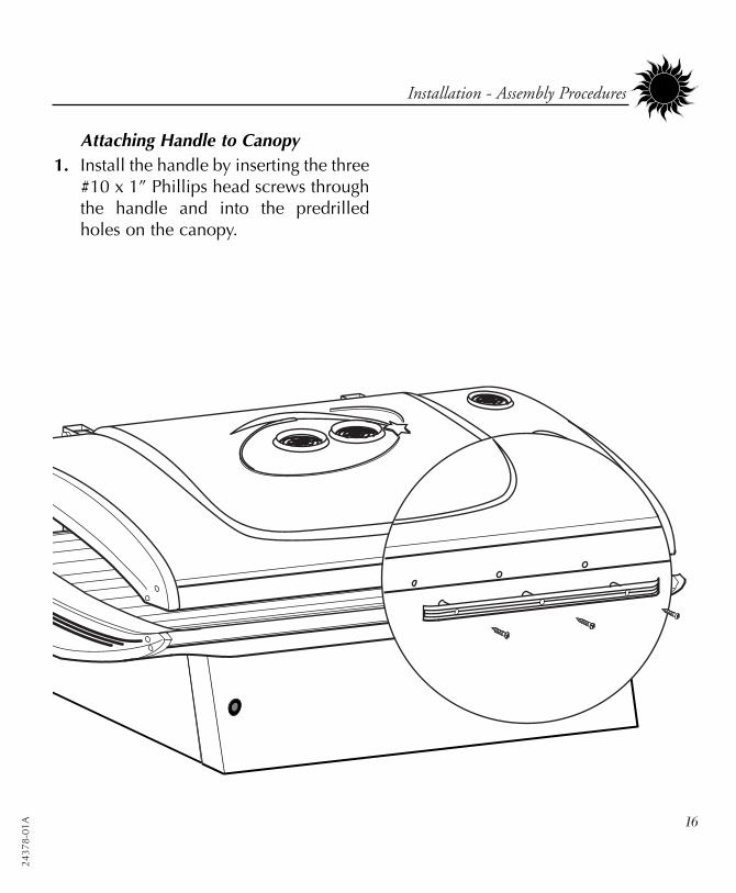
Installation - Assembly Procedures
Attaching Handle to Canopy1. Install the handle by inserting the three
#10 x 1” Phillips head screws throughthe handle and into the predrilledholes on the canopy.
24378-01A
17
Installation - Assembly Procedures
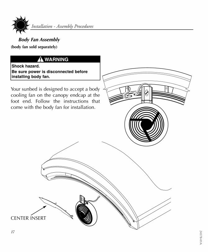
Body Fan Assembly (body fan sold separately)
Your sunbed is designed to accept a bodycooling fan on the canopy endcap at thefoot end. Follow the instructions thatcome with the body fan for installation.
CENTER INSERT
WARNINGShock hazard.Be sure power is disconnected beforeinstalling body fan.
2437
8-01
A 18
Installation - Electrical Connections
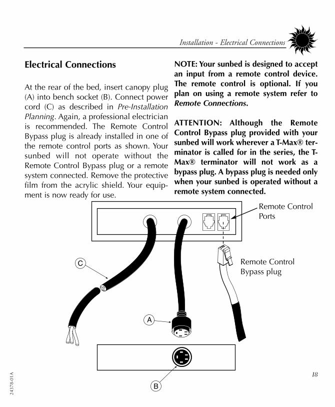
Electrical Connections
At the rear of the bed, insert canopy plug(A) into bench socket (B). Connect powercord (C) as described in Pre-InstallationPlanning. Again, a professional electricianis recommended. The Remote ControlBypass plug is already installed in one ofthe remote control ports as shown. Yoursunbed will not operate without theRemote Control Bypass plug or a remotesystem connected. Remove the protectivefilm from the acrylic shield. Your equip-ment is now ready for use.
NOTE: Your sunbed is designed to acceptan input from a remote control device.The remote control is optional. If youplan on using a remote system refer toRemote Connections.
ATTENTION: Although the RemoteControl Bypass plug provided with yoursunbed will work wherever a T-Max® ter-minator is called for in the series, the T-Max® terminator will not work as abypass plug. A bypass plug is needed onlywhen your sunbed is operated without aremote system connected.
Remote ControlBypass plug
Remote ControlPorts

24378-01A
19
Installation - Remote Connections
Remote Connections
Your sunbed incorporates advanced circuitryallowing it to connect and communicate withmost remote control systems. If a remote sys-tem is to be used, first determine whether theremote system is a T-Max® System or a stan-dard remote system operating with a controlrelay. Follow the appropriate instructions foryour system type.
T-Max® ProductsThe T-Max® remote systems offer the ultimatein sunbed control, while allowing the tannereasy straightforward operation. Your sunbed isconfigured to directly connect to this system.The circuitry inside your sunbed eliminates theneed for the T-Max® 1A or 3A when connect-ing to the T-Max® Manager series. Yoursunbed supports the auto addressing feature ofthe latest T-Max® Manager models and the fol-lowing parameters: 2, 5, 6, 7, 8, 9, 10, 14, 15and 23. See your T-Max® manual for descrip-tions of these parameters and how they func-tion. See Troubleshooting, “My salon suf-fers...”, for information about parameter 23.
T-Max® Manager Remote System This system is ideal for multiple sunbed instal-lations. Simply connect the RJ-22 modularcable(s), described in the T-Max® Managermanual, into the remote port(s) located on theback of your sunbed and follow the instruc-tions that came with your remote system, not-ing figure 1. If you have an older T-Max®
Manager that doesn’t support autoaddressing, set the address, or “id”, ofeach sunbed manually as described inSetting the address manually. You canplace your sunbed at any location inthe series.
figure 1NOTE: A T-Max® 1A can be
substituted for the 3A in figure 1.
CAUTIONThe remote connection is not designed to supplyor accept high voltage, nor can it provide powerto an external timer. The sunbed’s remote inter-face circuitry operates on 5 volts, attempting toconnect it to any higher voltages will damage thesunbed as well as void your warranty.
2437
8-01
A 20
Installation - Remote Connections
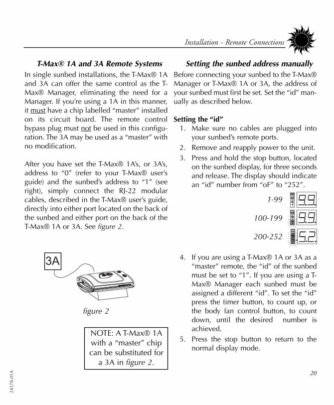
T-Max® 1A and 3A Remote SystemsIn single sunbed installations, the T-Max® 1Aand 3A can offer the same control as the T-Max® Manager, eliminating the need for aManager. If you’re using a 1A in this manner,it must have a chip labelled “master” installedon its circuit board. The remote controlbypass plug must not be used in this configu-ration. The 3A may be used as a “master” withno modification.
After you have set the T-Max® 1A’s, or 3A’s,address to “0” (refer to your T-Max® user’sguide) and the sunbed’s address to “1” (seeright), simply connect the RJ-22 modularcables, described in the T-Max® user’s guide,directly into either port located on the back ofthe sunbed and either port on the back of theT-Max® 1A or 3A. See figure 2.
Setting the sunbed address manuallyBefore connecting your sunbed to the T-Max®Manager or T-Max® 1A or 3A, the address ofyour sunbed must first be set. Set the “id” man-ually as described below.
Setting the “id” 1. Make sure no cables are plugged into
your sunbed’s remote ports.2. Remove and reapply power to the unit.3. Press and hold the stop button, located
on the sunbed display, for three secondsand release. The display should indicatean “id” number from “oF” to “252”.
4. If you are using a T-Max® 1A or 3A as a“master” remote, the “id” of the sunbedmust be set to “1”. If you are using a T-Max® Manager each sunbed must beassigned a different “id”. To set the “id”press the timer button, to count up, orthe body fan control button, to countdown, until the desired number isachieved.
5. Press the stop button to return to thenormal display mode.
NOTE: A T-Max® 1Awith a “master” chipcan be substituted for
a 3A in figure 2.
1-99
100-199
200-252
figure 2
24378-01A
Installation - Remote Connections
figure 3
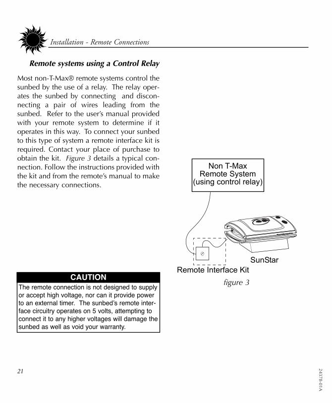
Remote systems using a Control Relay
Most non-T-Max® remote systems control thesunbed by the use of a relay. The relay oper-ates the sunbed by connecting and discon-necting a pair of wires leading from thesunbed. Refer to the user’s manual providedwith your remote system to determine if itoperates in this way. To connect your sunbedto this type of system a remote interface kit isrequired. Contact your place of purchase toobtain the kit. Figure 3 details a typical con-nection. Follow the instructions provided withthe kit and from the remote’s manual to makethe necessary connections.
CAUTIONThe remote connection is not designed to supplyor accept high voltage, nor can it provide powerto an external timer. The sunbed’s remote inter-face circuitry operates on 5 volts, attempting toconnect it to any higher voltages will damage thesunbed as well as void your warranty.
21
2437
8-01
A 22
peration
Before You Tan
Before using your sunbed, please note thefollowing important precautions.
• Your skin should be free of cosmetics,tanning oils, or other body lotionsprior to tanning except for thosespecifically made for use with tanningdevices. However, do not remove nat-ural body oils by bathing or showeringimmediately before tanning.
• Your hair should be free of gels,mousses, sprays, or other hair productsprior to tanning. These products cancause damage to the sunbed acrylic.As an alternative, a shower cap ortowel can be worn to keep treated hairaway from the sunbed surfaces.
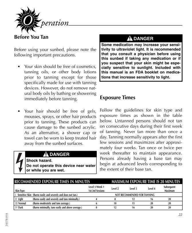
RECOMMENDED EXPOSURE TIMES IN MINUTES MAXIMUM EXPOSURE TIME IS 20 MINUTESLevel 1/Week 1 Level 2 Level 3 Level 4 Subsequent
Skin Type: 1st-3rd Sessions MaximumI Sensitive Skin (Burns easily and severely and does not tan.) NOT RECOMMENDED FOR TANNINGII Light (Burns easily and severely and tans minimally.) 4 8 12 16 20III Normal (Burns moderately and tans average.) 6 10 15 20 20IV Dark (Burns minimally, tans easily and above average.) 8 12 16 20 20
Exposure Times
Follow the guidelines for skin type andexposure times as shown in the tablebelow. Untanned persons should not tanon consecutive days during their first weekof tanning. Never tan more than once aday. Tanning normally appears after the firstfew sessions and maximizes after approxi-mately four weeks. Tan once or twice perweek thereafter to maintain appearance.Persons already having a base tan maybegin at advanced levels corresponding tothe extent of their base tan.
DANGERSome medication may increase your sensi-tivity to ultraviolet light. It is recommendedthat you consult a physician before usingthis sunbed if taking any medication or ifyou suspect that your skin might be espe-cially sensitive to sunlight. Included withthis manual is an FDA booklet on medica-tions that increase sensitivity to light.
DANGERShock hazard.Do not operate this device near wateror while you are wet.
24378-01A
23
1. Lift the canopy, lie down on the bench(face up), lower the canopy toward yourbody using the canopy handle. See SafetyInformation for positioning instructions.
2. Put on your safety goggles.
3. Assuming the remote system has been setto allow a pre-tanning delay time, the timerdisplay (E) will repeatedly flash the delaysymbol “dL” and then the remaining delaytime. Press the timer button (G) or waituntil the delay time has expired to beginthe tanning session. The lamps will turn onand the timer will begin to count down.
4. When the timer reaches 0 the lamps turnoff. If you want to stop your session beforetime expires, press the stop button (F).
5. Raise the canopy by using the outer edge,do not push up on the acrylic shield. Thecooling fans run for a period of time afterthe lamps shut off to aid in cooling thesunbed. The timer will indicate “..” as areminder to clean the sunbed. After thesunbed is cleaned press the timer buttonand the display will return to “0”.
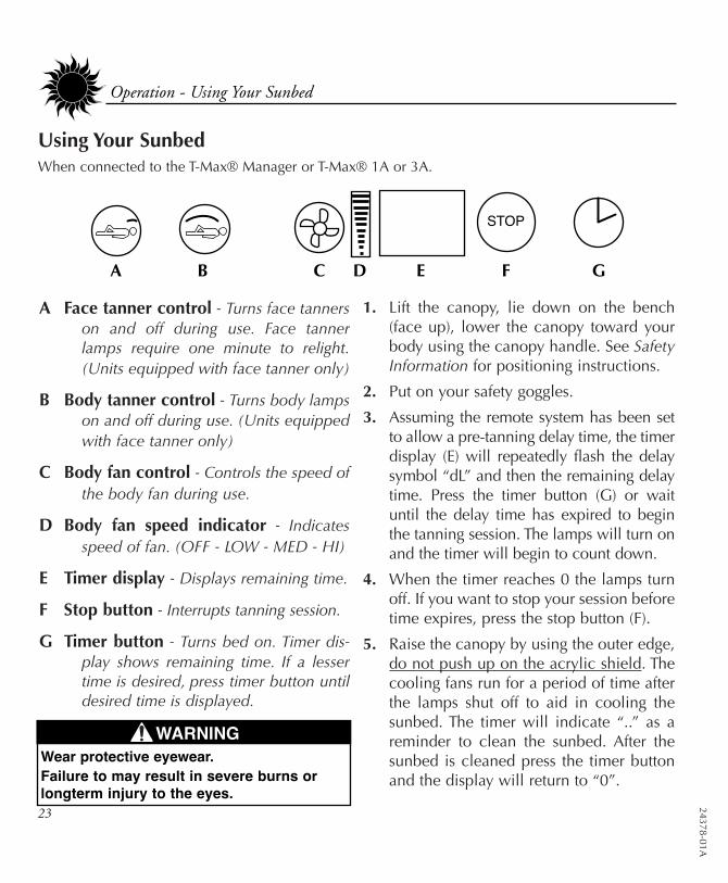
Using Your SunbedWhen connected to the T-Max® Manager or T-Max® 1A or 3A.
A Face tanner control - Turns face tannerson and off during use. Face tannerlamps require one minute to relight.(Units equipped with face tanner only)
B Body tanner control - Turns body lampson and off during use. (Units equippedwith face tanner only)
C Body fan control - Controls the speed ofthe body fan during use.
D Body fan speed indicator - Indicatesspeed of fan. (OFF - LOW - MED - HI)
E Timer display - Displays remaining time.
F Stop button - Interrupts tanning session.
G Timer button - Turns bed on. Timer dis-play shows remaining time. If a lessertime is desired, press timer button untildesired time is displayed.
A B C D E F G
Operation - Using Your Sunbed
WARNINGWear protective eyewear.Failure to may result in severe burns orlongterm injury to the eyes.
2437
8-01
A 24
Operation - Using Your Sunbed
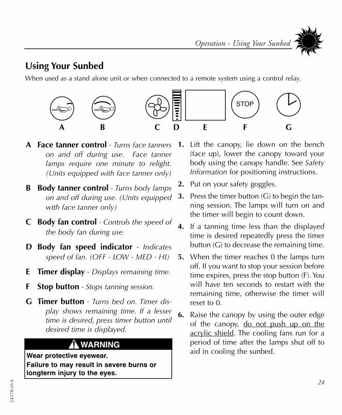
Using Your SunbedWhen used as a stand alone unit or when connected to a remote system using a control relay.
1. Lift the canopy, lie down on the bench(face up), lower the canopy toward yourbody using the canopy handle. See SafetyInformation for positioning instructions.
2. Put on your safety goggles.
3. Press the timer button (G) to begin the tan-ning session. The lamps will turn on andthe timer will begin to count down.
4. If a tanning time less than the displayedtime is desired repeatedly press the timerbutton (G) to decrease the remaining time.
5. When the timer reaches 0 the lamps turnoff. If you want to stop your session beforetime expires, press the stop button (F). Youwill have ten seconds to restart with theremaining time, otherwise the timer willreset to 0.
6. Raise the canopy by using the outer edgeof the canopy, do not push up on theacrylic shield. The cooling fans run for aperiod of time after the lamps shut off toaid in cooling the sunbed.
A B C D E F G
A Face tanner control - Turns face tannerson and off during use. Face tannerlamps require one minute to relight.(Units equipped with face tanner only)
B Body tanner control - Turns body lampson and off during use. (Units equippedwith face tanner only)
C Body fan control - Controls the speed ofthe body fan during use.
D Body fan speed indicator - Indicatesspeed of fan. (OFF - LOW - MED - HI)
E Timer display - Displays remaining time.
F Stop button - Stops tanning session.
G Timer button - Turns bed on. Timer dis-play shows remaining time. If a lessertime is desired, press timer button untildesired time is displayed.
WARNINGWear protective eyewear.Failure to may result in severe burns orlongterm injury to the eyes.
24378-01A
25
are and Maintenance
Cleaning After Use
Clean and disinfect your tanning bed’sbench and canopy after each use. Use anon-abrasive disinfectant cleaner that doesnot contain ammonia or ammonia deriva-tives. Ammonia may damage the acrylicshield. Spray the acrylic lightly with disin-fectant and wipe dry with a clean soft cloth.We recommend SunQuest® disinfectant andSunQuest® acrylic cleaner.
Thorough Periodic Cleaning
IntroductionThe cooling fans draw air through the bedand over time will cause a dust buildup onthe lamps and reflectors. This will reducethe tanning effectiveness of the bed. Whena dust buildup is observed, it is necessary tothoroughly clean the inside of the benchand canopy.
Cleaning the Canopy and BenchStep 1 Remove the acrylic shields and
lamps as described in Lamp andAcrylic Replacement.
Step 2 With a soft cloth, wipe the entirelength of each lamp to removeany film buildup.
Step 3 Clean both sides of the acrylicshields with a non-ammonia dis-infectant cleaner.
Step 4 Wipe the reflectors with a cleandamp cloth.
Step 5 Re-install the lamps and acrylicshields.
Mechanical Inspection
Your tanning bed has been built for years ofservice. To ensure trouble-free operationthroughout its life, inspect the unit’smechanical integrity every 400-500 hoursof use.
• Inspect the unit’s fasteners verifyingthat all are firmly in place.
• Inspect gas springs for signs of wear.Gas springs that will not hold thecanopy in the full open position whenraised should be immediately replaced.See Troubleshooting.
• Inspect the AC power cord and itsconnections.
• Inspect the acrylic. Broken, cracked orbadly scratched acrylics should beimmediately replaced.
WARNINGShock hazard.Disconnect power before removingany protective covers.
2437
8-01
A 26
Lamp and Acrylic Replacement
IntroductionTo be assured of maximum tanning effec-tiveness, change lamps after approximate-ly 800-1000 hours of use. Tanning willcontinue after this time but at a slowerrate. To ensure trouble-free operation ofyour sunbed, replace the lamp starterswhenever the lamps are replaced.
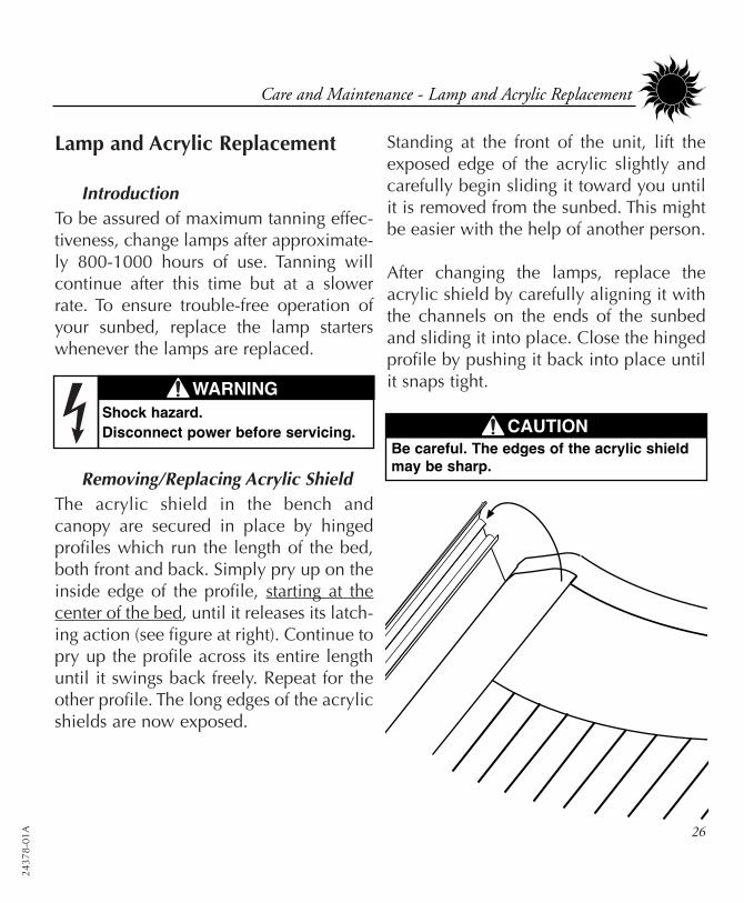
Removing/Replacing Acrylic ShieldThe acrylic shield in the bench andcanopy are secured in place by hingedprofiles which run the length of the bed,both front and back. Simply pry up on theinside edge of the profile, starting at thecenter of the bed, until it releases its latch-ing action (see figure at right). Continue topry up the profile across its entire lengthuntil it swings back freely. Repeat for theother profile. The long edges of the acrylicshields are now exposed.
Standing at the front of the unit, lift theexposed edge of the acrylic slightly andcarefully begin sliding it toward you untilit is removed from the sunbed. This mightbe easier with the help of another person.
After changing the lamps, replace theacrylic shield by carefully aligning it withthe channels on the ends of the sunbedand sliding it into place. Close the hingedprofile by pushing it back into place untilit snaps tight.
Care and Maintenance - Lamp and Acrylic Replacement
CAUTIONBe careful. The edges of the acrylic shieldmay be sharp.
WARNINGShock hazard.Disconnect power before servicing.
24378-01A
27
Care and Maintenance - Lamp and Acrylic Replacement
Removing/Replacing LampsAfter removing the acrylic shield, replacelamps as follows.
Step 1 Grasp the lamp at one end andat the middle and turn the lampone quarter turn. Gently removethe lamp from its holders.
Step 2 Reinstall the lamp by insertingthe pins located on the ends ofthe lamp into the slots on top ofthe lamp holders and turn thelamp a quarter turn. It shouldclick in place.
Recommended Replacement LampsWe recommend using the lamps specifiedbelow. Use of uncertified lamps is a viola-tion of Federal regulations and will voidyour warranty. These lamps have an aver-age life of 800-1000 hours of effectivetanning use. Lamps used longer than thatbegin to lose their effectiveness eventhough they continue to light.
Recommended Replacement AcrylicsAcrylics vary greatly over time in theirability to effectively transmit UV light.Acrylics sold by ETS have been life testedto ensure proper transmission throughouttheir useful life.
ONLY THE FOLLOWING LAMPS HAVE BEEN CERTIFIED FOR USE IN THIS EQUIPMENT:SPEED® 175 Wolff® Model SPD75-T12 PREHEAT BIPIN (Bench lamps)
SPEED® 205 Wolff® Model SPD71-T12-205 BIPIN (Canopy lamps)
Heraeus E400 HPT, Philips Model HPA 400/30s or CosmoTech Model 23045(SolarMax™ IFT facial unit in ZX30 3F)
2437
8-01
A 28
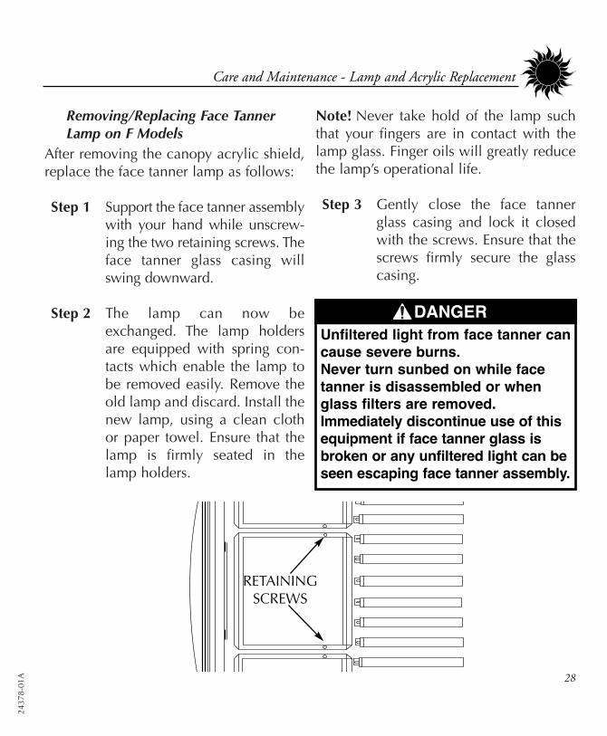
Removing/Replacing Face TannerLamp on F Models
After removing the canopy acrylic shield,replace the face tanner lamp as follows:
Step 1 Support the face tanner assemblywith your hand while unscrew-ing the two retaining screws. Theface tanner glass casing willswing downward.
Step 2 The lamp can now beexchanged. The lamp holdersare equipped with spring con-tacts which enable the lamp tobe removed easily. Remove theold lamp and discard. Install thenew lamp, using a clean clothor paper towel. Ensure that thelamp is firmly seated in thelamp holders.
Note! Never take hold of the lamp suchthat your fingers are in contact with thelamp glass. Finger oils will greatly reducethe lamp’s operational life.
Step 3 Gently close the face tannerglass casing and lock it closedwith the screws. Ensure that thescrews firmly secure the glasscasing.
RETAININGSCREWS
Care and Maintenance - Lamp and Acrylic Replacement
DANGERUnfiltered light from face tanner cancause severe burns.Never turn sunbed on while facetanner is disassembled or whenglass filters are removed. Immediately discontinue use of thisequipment if face tanner glass isbroken or any unfiltered light can beseen escaping face tanner assembly.

24378-01A
29
roubleshooting
Problem SolutionSunbed not tanning
Lamps fail to light and timer dis-play is blank
One or more lamps fail to light
The canopy will not stay up
The face tanners will not come on
The last minute of tanning timedoes not count down from 59 sec-onds, but some time less than 59seconds
I forgot what address, or “id”, I setmy sunbed to
1. Clean sunbed, see Thorough Periodic Cleaning.2. Ensure supply voltage is between 208 and 230V AC.3. Replace lamps if lamp hours are greater than 800hrs.4. Replace acrylic.
1. Make sure the unit is connected to a power source.2. Check source of AC power. Reset circuit breaker or replace fuse.
1. Check that lamp is installed correctly.2. Switch unlit lamp with a lamp that lights, if new lamp lights
and old lamp still does not, replace old lamp.
NOTE: Gas springs are manufactured to hold the canopy in itsfully open position as well as allow it to rest fully closed. If leftopen for an extended period of time some creep down mayoccur. This is considered normal. Keep the unit closed whennot in use. If the canopy will not stay fully open when raised...
1. Raise and lower the canopy a few times to lubricate gas springinternal seals.
2. Replace gas springs.
1. Face tanner operation is initially delayed by 5 seconds.2. Face tanners will not relight for 1 minute if turned off.3. Replace face tanner lamp, see Removing/Replacing Face
Tanner Lamp on F Models.
If the timer button has been pressed to decrease tanning timeduring the session, the time expired in the current minute issubtracted from the last minute.
By holding the body fan button for 3 seconds the timer displaywill briefly display three numbers; the installed timer softwareversion, a factory set timer code and then the sunbed’s “id”number.

2437
8-01
A 30
Problem SolutionTimer display is indicating Er 91
Timer display is indicating Er 92
Timer display is indicating Er 93
Timer display is indicating Er 94
Timer display changes to indicatea tanning time after the timer but-ton is pressed but lamps do notcome on
My bed is connected to the T-Max® Manager remote systemand when the delay time hasexpired the timer display startscounting down but the bed lightsdo not come on
My bed won’t work with the T-Max® Manager remote system
Timer display continues to show a0 after the timer button is pressed
Timer software error. Disconnect and reapply power to the unit.
Current sensor indicating unit is off when it should be on.Contact servicer.
Current sensor indicating unit is on when it should be off.Contact servicer.
Requested session time exceeds maximum time allowed.
1. Bypass plug is not installed, see Electrical Connections.2. A non-SunStar® bypass has been used. See Electrical
Connections.3. If remote is being used, other than T-Max® Manager, the exter-
nal timer may not be activated.4. Remote wiring is incorrect, see the instructions provided with
the remote interface kit.
The auto start feature of the remote system is disabled, see theinstructions provided with your remote system.
1. The sunbed must first be set to a unique address, see RemoteConnections.
2. The bypass or terminator plug may be installed in the series inan inappropriate location. Plug the bypass plug only into thebed at the end of the series.
1. T-Max® Manager remote system has not yet been set. 2. Sunbed address is not set correctly, see Remote Connections.
24378-01A
31
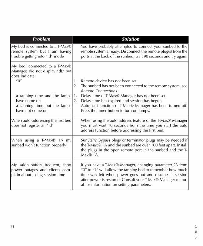
Problem SolutionMy bed is connected to a T-Max®remote system but I am havingtrouble getting into “id” mode
My bed, connected to a T-Max®Manager, did not display “dL” butdoes indicate:
“0”
a tanning time and the lampshave come ona tanning time but the lampshave not come on
When auto-addressing the first beddoes not register an “id”
When using a T-Max® 1A mysunbed won’t function properly
My salon suffers frequent, shortpower outages and clients com-plain about losing session time
You have probably attempted to connect your sunbed to theremote system already. Disconnect the remote plug(s) from theports at the back of the sunbed, wait 90 seconds and try again.
1. Remote device has not been set.2. The sunbed has not been connected to the remote system, see
Remote Connections.1. Delay time of T-Max® Manager has not been set.2. Delay time has expired and session has begun.
Auto start function of T-Max® Manager has been turned off.Press the timer button to turn on lamps.
When using the auto address feature of the T-Max® Manageryou must wait 10 seconds from the time you start the autoaddress function before addressing the first bed.
SunStar® Bypass plugs or terminator plugs may be needed ifthe T-Max® 1A and the sunbed are over 100 feet apart. Installthe plugs in the open remote port in the sunbed and the T-Max® 1A.
If you have a T-Max® Manager, changing parameter 23 from“0” to “1” will allow the tanning bed to remember how muchtime was left when power goes out and resume its sessionafter power is restored. Consult your T-Max® Manager manu-al for information on setting parameters.
2437
8-01
A
L-Z
X30
24378-01A
L-Z
X30
-3F

2437
8-01
A
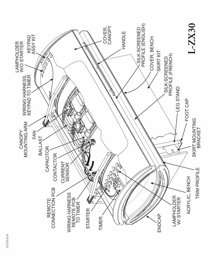
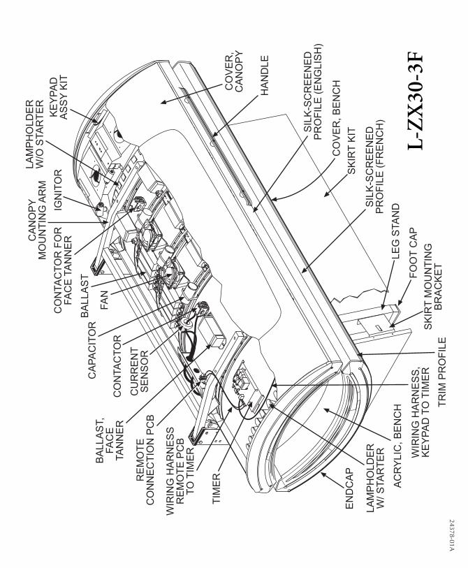
Parts ListThis is a list of parts which may be replaced by
the consumer. Care should be taken when replac-ing anything related to electrical wiring. We rec-ommend contacting a professional electrician.
When calling for parts, first state your bed modelas L-ZX30 or L-ZX30-3F. Then refer to this list andpreceding illustrations for proper part identification.
Acrylic, BenchAcrylic, Canopy*Ballast, SPEED®systemBallast, Face Tanner 400WBushing, Bronze 10mm*Body Fan Kit* (optional)Canopy Mounting ArmCapacitor, 75uFContactor (Relay)Contactor for Face TannerCover, BenchCover, CanopyEndcap, Kit (with inserts)FanFoot CapGas Spring Cover Panel*Gas Springs*HandleHardware Blister Pack*Hour Counter*Keypad Assy KitLamp Holder w/ StarterLamp Holder w/o StarterLamp Holder, Face Tanner*Lamps*Latch Key for Front Skirt Panel*Leg Stand and Skirt Bracket Kit
Record this information for ease of service:
Date of purchase:
Bench serial number:
Canopy serial number:
Manual*Pillow*Profile* (blank)Remote Connection PCBRemote Control Bypass Plug*Schematic Packet*Silk-screened Profile (English)Silk-screened Profile (French)Skirt KitStarter, K-12 (main lamps)Starter, Face Tanner (ignitor)Thermostat* (for face tanner)TimerTrim Profile, (grey) full lengthTrim Profile, (grey) canopy rear middle*Trim Profile, (grey) canopy rear ends*Wiring Harness, Keypad to TimerWiring Harness, Remote PCB to Timer
* Not shown
This sunbed utilizes a proprietary system ofcomponents known as the SPEED® system.Only certified SPEED® system componentsmay be used as replacements, includinglamps and ballasts.

ZX30 ZX30 3FSize
Weight (Pounds) 469 476
Minimum Room Size 7’ x 9’ 7’ x 9’
Electrical -
Voltage (AC) 220 220
Amperage 17 22
Circuit Breaker (Amps) 30 30
Outlet Hardwire Hardwire
Main Lamps (bench) SPEED® 175 SPEED® 175
Main Lamps (canopy) SPEED® 205 SPEED® 205
Ballasts SPEED®system SPEED®system
Face Tanner NA SolarMax™ IFT
FT Ballasts NA 400W
Cooling System 230cfm “Turbo”(optional) 230cfm “Turbo”(optional)
Timer System Digital Digital
Max. Exposure Time 20minutes 20minutes
Back-up Timer On-board “Watchdog” On-board “Watchdog”
Remote Capability T-Max® compatible T-Max® compatible
CALL FOR SERVICE OR QUESTIONS: 1•800•449•36056270 Corporate Drive, Indianapolis, IN 46278-2900
In Canada call 1-800-661-6292 or 519-469-3166


![[ZX] Changement d'un joint de culasse sur une ZX 1xud9te.free.fr/Download/Tutorial/[ZX]Changement_joint... · 2008. 11. 30. · [ZX] Changement d'un joint de culasse sur une ZX 1.9D](https://img.dokumen.tips/doc/110x75/60d4a95281e5cb60cf64541b/zx-changement-dun-joint-de-culasse-sur-une-zx-zxchangementjoint-2008.jpg)