Embed Size (px)
Citation preview
SUNTEST CPS / CPS+Operating Manual
Operating manual SUNTEST CPS / CPS+
- 2 -
1 Notes for safe operation.................................................................................................................................41.1 Explanation of the pictorial signs ..................................................................................................................61.2 Instructions for safe operation ......................................................................................................................7
2 Installation of unit ..........................................................................................................................................82.1 Supply schedule ..........................................................................................................................................82.2 Packing material ..........................................................................................................................................82.3 Location requirements ..................................................................................................................................92.4 Installation ...................................................................................................................................................9
3 Description of unit ........................................................................................................................................ 103.1 Description of Suntest CPS ....................................................................................................................... 103.2 Description of Suntest CPS+ ..................................................................................................................... 103.3 Components with similar construction SUNTEST CPS / CPS+ .................................................................. 11
4 Description of functions ............................................................................................................................... 124.1 Radiation and filtering ................................................................................................................................. 124.2 Ventilation circuits ...................................................................................................................................... 124.3 Spectral distribution with additional filters ................................................................................................... 134.4 Sensor system in SUNTEST CPS+ ........................................................................................................... 144.5 Safety devices ........................................................................................................................................... 154.6 Safety markings ......................................................................................................................................... 15
5 Accessories ................................................................................................................................................... 16
6 Commissioning ............................................................................................................................................. 186.1 Mounting of specimen table ....................................................................................................................... 186.2 Assembling the radiation system ............................................................................................................... 186.3 Connection to power supply ....................................................................................................................... 21
7 Operation and shutdown ............................................................................................................................. 227.1 Configuration of unit ................................................................................................................................... 227.2 Standard testing procedure ........................................................................................................................ 227.3 Testing procedure with optional unit ............................................................................................................ 227.4 Operation of SUNTEST CPS ...................................................................................................................... 237.5 Operation of SUNTEST CPS+ program controller ...................................................................................... 237.6 Data transfer to a PC ................................................................................................................................. 247.7 Shutdown ................................................................................................................................................... 24
8 Calibration .................................................................................................................................................... 258.1 Calibration of irradiance with the XenoCal Global Sensor ............................................................................ 258.2 Calibration of irradiance with the Radialux Global Sensor ........................................................................... 268.3 Calibration of the black standard temperature ............................................................................................. 27
9 Cleaning / Consumables .............................................................................................................................. 289.1 Cleaning ..................................................................................................................................................... 289.2 Consumables / Spare parts ........................................................................................................................ 29
10 Maintenance ................................................................................................................................................. 3010.1 Maintenance and care ................................................................................................................................ 3010.2 Commissioning .......................................................................................................................................... 30
11 Technical data .............................................................................................................................................. 31
Content Page
- 3 -
Operating manual SUNTEST CPS / CPS+
List of graphics Page
Fig. 1 Description of unit Suntest CPS ................................................................................................................. 10Fig. 2 Description of unit Suntest CPS+............................................................................................................... 10Fig. 3 Components with similar construction SUNTEST CPS / CPS+ .................................................................. 11Fig. 4 Test chamber ............................................................................................................................................. 11Fig. 5 Radiation and filtering ................................................................................................................................. 12Fig. 6 Ventilation circuits ...................................................................................................................................... 12
Spectral distribution with additional filters ................................................................................................... 13Fig. 7 Sensor system in the SUNTEST CPS+ ..................................................................................................... 14Fig. 8 Safety devices ........................................................................................................................................... 15Fig. 9 Safety markings ......................................................................................................................................... 15Fig. 10 Mounting of specimen table ....................................................................................................................... 18Fig. 11 Components of the radiation system .......................................................................................................... 18Fig. 12 Opening the assembly compartment .......................................................................................................... 19Fig. 13 Installation of optical filters ......................................................................................................................... 19Fig. 14 Installation of Xenon lamp.......................................................................................................................... 20Fig. 15 Installation of mirrors .................................................................................................................................. 20Fig. 16 Closing the assembly compartment ........................................................................................................... 21Fig. 17 Connection to power supply ....................................................................................................................... 21Fig. 18 Standard testing procedure ........................................................................................................................ 22Fig. 19 Operation of SUNTEST CPS ...................................................................................................................... 23Fig. 20 Operation of SUNTEST CPS+ program controller ....................................................................................... 23Fig. 21 Data transfer to a PC (pin configuration) ..................................................................................................... 24Fig. 22 Calibration of irradiance with the XenoCal Global Sensor ............................................................................ 25Fig. 23 Calibration of irradiance with the Radialux Global Sensor ........................................................................... 26Fig. 24 Calibration of the black standard temperature ............................................................................................. 27
Operating manual SUNTEST CPS / CPS+
- 4 -
Dear user,
Please note that certain kinds of work must only be carried out by personnel who are suitably qualified:
• The SUNTEST CPS/CPS+ may be operated only by trained und authorized laboratory personnel,• The unit should only be cleaned by trained personnel.
• This operating manual describes the SUNTEST CPS and the SUNTEST CPS+ weathering units.• Please read the Operating Manual carefully before using the SUNTEST CPS/CPS+.
You will then be able to exploit all the advantages that the device offers and prevent damage.• If unusual problems occur, that have not been treated in sufficient detail in this operating manual, please contact the
supplier for your own safety.
1 Notes for safe operation
ATLAS Material Testing Technology B.VVogelsbergstr. 22
63589 Linsengericht / AltenhaßlauDeutschland
Phone ++ 49 / 6051 / 707-140
Fax ++ 49 / 6051 / 707-149
- 5 -
Operating manual SUNTEST CPS / CPS+
1 Notes for safe operation
Dear User:
• This unit has been manufactured according to the state-of-the-art and is operationally safe. Nonetheless, there maybe some danger from this unit, especially if it is operated by personnel who are not adequately trained, or if it is usedin an improper manner, and not for its intended purpose.
• For personnel working with or on this unit, the operating agency must provide written instructions, in an easy-to-understand form, based on these instructions, and make it available in the natural language of the employee (FRG:Accident Prevention Act, UVV VGB 1 § 7, 2).
• Based on these instructions, train the operating and cleaning personnel in the function, operation and maintenanceof this unit.
• The contents of this operating manual are subject to change at any time without prior notice.• The German version of this operating manual is binding in the case of translations in other, foreign languages.• For reasons of safety, changes or modifications to the unit on your own initiative are not permitted.
Please keep this operating manual carefully and accessibly in the vicinity of your instrument, so that safetyinstructions and important information can be looked up at any time.
Trade marks:All the trade marks in the instructions are the exclusive property of the respective manufacturers.
Copyright©
1999, ATLAS MTT BV • D-63589 Linsengericht-Altenhaßlau • Germany
Edition dated:March 1999
Operating manual SUNTEST CPS / CPS+
- 6 -
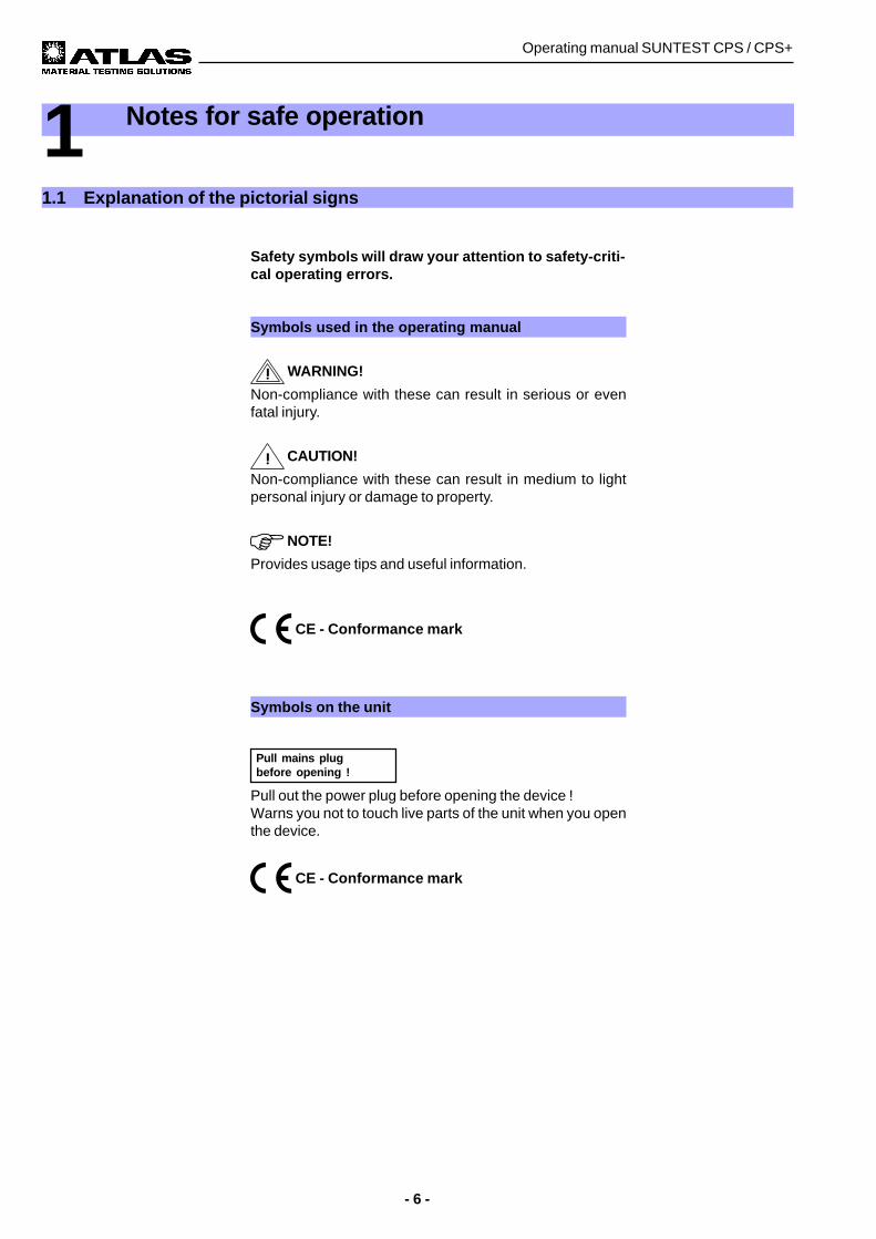
Safety symbols will draw your attention to safety-criti-cal operating errors.
Symbols used in the operating manual
WARNING!
Non-compliance with these can result in serious or evenfatal injury.
CAUTION!
Non-compliance with these can result in medium to lightpersonal injury or damage to property.
NOTE!
Provides usage tips and useful information.
CE - Conformance mark
Symbols on the unit
Pull out the power plug before opening the device !Warns you not to touch live parts of the unit when you openthe device.
CE - Conformance mark
1 Notes for safe operation
1.1 Explanation of the pictorial signs
Pull mains plugbefore opening !
- 7 -
Operating manual SUNTEST CPS / CPS+
1 Notes for safe operation
Please also follow the safety instructions in the individual chapters.
Usage as authorized:• SUNTEST CPS / CPS+ are used for exposure and weathering of material samples.• The unit is suitable for continuous operation.• The unit has been tested for electromagnetic compatibility and for installation in an industrial application.
Unauthorized usage:• No substances of materials that are inflammable or that can explode should be used in the test chamber.• No substances or materials that may release toxic substances in any form should be used in the test chamber.• The device must not be used for drying or heating objects or foodstuffs.
Safety instructions for commissioning:
WARNING - Pull out the power plug:
Coming in contact with live parts can result in a possibly fatal electrical shock. When assembling the irra-diance system, set the ON (I) / OFF (O) switch to the "OFF (O)" position and pull out the power plug. Securethe power plug from being inserted again.
WARNING - UV radiation being emitted:
If the specimen table is not used, UV radiation is emitted on the lower side of the unit and can result indamage to skin and retina. Always use the specimen table when the unit is running !
WARNING - UV radiation being emitted:
If the mirrors (figure 15) are not used, UV radiation is emitted on the upper side of the unit and can result indamage to skin and retina. Always mount the mirrors.
CAUTION - Danger of cuts and gashes:
The optical filters have sharp edges that may cause cuts and gashes.Always wear protective gloves when working on the radiation system.
The device fulfills the following safety specifications:• DIN EN Part 1:1991-11, Part 2:1995-06
Safety of machinery• DIN EN 60601 Part 1:1994-05
Safety regulations for electrically operated measuring, controlling, regulating and laboratory equipment. Generalrequirements.
• DIN EN 50178 (VDE0160): 1998-04Electronic equipment for use in power installations
• DIN EN 50082 (VDE 0839) Part 2:1997-11Electromagnetic compatibility, Professional Basic Norm, immunity from distortion. Part 1: Residential areas, busi-ness and industrial areas as well as small industries. Part 2: Industrial area.
Disposal:• Please dispose of the packing materials according to the applicable disposal guidelines. There is a list given in
chapter 2.2, "Packing Material".• Xenon lamps are special waste and may be sent to ATLAS MTT B.V. for disposal.• Old units contain re-usable materials. Therefore, please do not simply dispose of old units at the nearest garbage
dump, but ask your city or community administration for the possibilities of recycling.
1.2 Instructions for safe operation
Operating manual SUNTEST CPS / CPS+
- 8 -
2 Installation of unit
2.1 Supply schedule
The weathering unit is available in two versions: SUN-TEST CPS or SUNTEST CPS+.
The basic unit of SUNTEST CPS consists of:• Xenon lamp,• Optical filter "coated quartz filter segment",• UV mirror and light mirror,• Specimen table,• Sensor for measuring and regulating irradiance (E),• Control panel with rotary switch for infinite adjustment
of irradiance, Xenon lamp operating hour meter andswitch for igniting the Xenon lamp.
• ON (I) / OFF (O) switch.
SUNTEST CPS+ is equipped with the following:• Xenon lamp,• Optical filter "coated quartz filter segment",• UV mirror and light mirror,• Specimen table,• Sensor for measurement and control of irradiance (E),• Sensor for measurement and control of the black stan-
dard temperature (BST),• Sensor for measuring the test chamber temperature
(TCT),• Program controller with a display for displaying data
and keyboard for data input,• ON (I) / OFF (O) switch,• Serial RS 232-port for connection to a PC.
2.2 Packing material
• Polyethylene foam (PE)• Corrugated cardboard
- 9 -
Operating manual SUNTEST CPS / CPS+
2.3 Location requirements
Climatic conditions required for the place of instal-lation:• During continuous operation, the hot air emitted by the
air-cooling system results in a constantly changing cli-mate in the room. Therefore, the SUNTEST unit shouldonly be installed in air-conditioned, sufficiently ventila-ted places of installation.
• The places of installation must be kept free of dust.• The room temperature must be maintained between
18°C and 25°C.• The max. relative humidity should be 70%.
The requirement for coolant air is as follows:• 120 m³/h for lamp cooling and cooling of the test cham-
ber.
2 Installation of unit
2.4 Installation
Installation SUNTEST CPS / CPS+: • Dimensions of unit (width x depth x height):
780 mm x 350 mm x 350 mm,• Weight of unit approx. 30 kg,• The unit must be set up on a sufficiently stable labora-
tory bench with a non-flammable support underneath;the laboratory bench should be aligned so that it ishorizontal.
Caution - Overheating of the unit:
Blocking of the air inlet and air outlets can result inoverheating and damage to the unit!When installing the unit, the following minimum di-stances to the neighboring walls or objects must bemaintained:
to the front: 700 mmto the back: 500 mmto the top: 350 mmto both sides: 300 mm
Operating manual SUNTEST CPS / CPS+
- 10 -
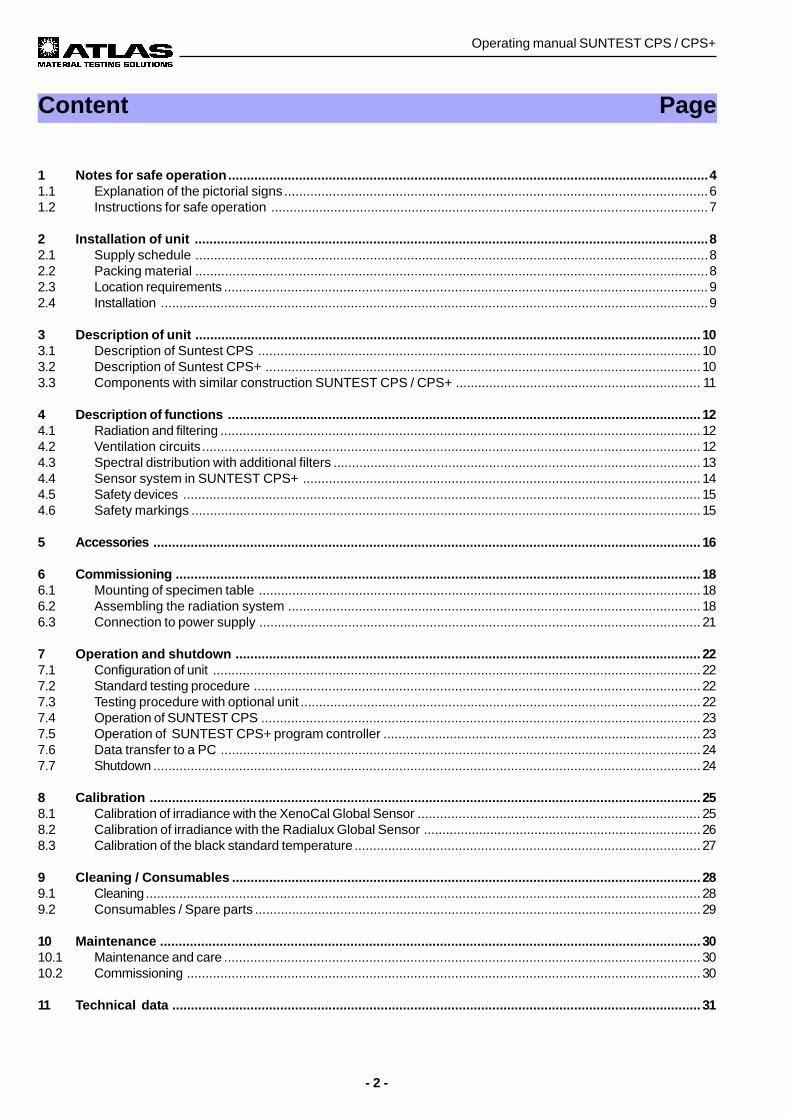
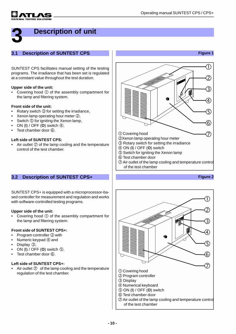
! Covering hood"Xenon lamp operating hour meter# Rotary switch for setting the irradiance$ ON (I) / OFF (O) switch% Switch for igniting the Xenon lamp& Test chamber door' Air outlet of the lamp cooling and temperature control
of the test chamber
Figure 1
3 Description of unit
Figure 2
! Covering hood" Program controller# Display$ Numerical keyboard% ON (I) / OFF (O) switch& Test chamber door' Air outlet of the lamp cooling and temperature control
of the test chamber
3.1 Description of SUNTEST CPS
SUNTEST CPS facilitates manual setting of the testingprograms. The irradiance that has been set is regulatedat a constant value throughout the test duration.
Upper side of the unit:• Covering hood ! of the assembly compartment for
the lamp and filtering system.
Front side of the unit:• Rotary switch # for setting the irradiance,• Xenon lamp operating hour meter ",• Switch % for igniting the Xenon lamp,• ON (I) / OFF (O) switch $,• Test chamber door &.
Left side of SUNTEST CPS:• Air outlet ' of the lamp cooling and the temperature
control of the test chamber.
3.2 Description of SUNTEST CPS+
SUNTEST CPS+ is equipped with a microprocessor-ba-sed controller for measurement and regulation and workswith software-controlled testing programs.
Upper side of the unit:• Covering hood ! of the assembly compartment for
the lamp and filtering system.
Front side of SUNTEST CPS+:• Program controller " with• Numeric keypad $ and• Display #,• ON (I) / OFF (O) switch %,• Test chamber door &.
Left side of SUNTEST CPS+:• Air outlet '(of the lamp cooling and the temperature
regulation of the test chamber.
- 11 -
Operating manual SUNTEST CPS / CPS+
3 Description of unit
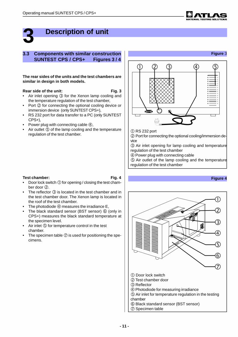
Figure 3
! RS 232 port" Port for connecting the optional cooling/immersion de-vice# Air inlet opening for lamp cooling and temperatureregulation of the test chamber$ Power plug with connecting cable% Air outlet of the lamp cooling and the temperatureregulation of the test chamber
Figure 4
! Door lock switch" Test chamber door# Reflector$ Photodiode for measuring irradiance% Air inlet for temperature regulation in the testingchamber& Black standard sensor (BST sensor)' Specimen table
Test chamber: Fig. 4• Door lock switch ! for opening / closing the test cham-
ber door ".• The reflector # is located in the test chamber and in
the test chamber door. The Xenon lamp is located inthe roof of the test chamber.
• The photodiode $ measures the irradiance E,• The black standard sensor (BST sensor) & (only in
CPS+) measures the black standard temperature atthe specimen level.
• Air inlet % for temperature control in the testchamber.
• The specimen table ' is used for positioning the spe-cimens.
3.3 Components with similar constructionSUNTEST CPS / CPS+ Figures 3 / 4
The rear sides of the units and the test chambers aresimilar in design in both models.
Rear side of the unit: Fig. 3• Air inlet opening # for the Xenon lamp cooling and
the temperature regulation of the test chamber,• Port " for connecting the optional cooling device or
immersion device (only SUNTEST CPS+),• RS 232 port for data transfer to a PC (only SUNTEST
CPS+),• Power plug with connecting cable $,• Air outlet % of the lamp cooling and the temperature
regulation of the test chamber.
Operating manual SUNTEST CPS / CPS+
- 12 -
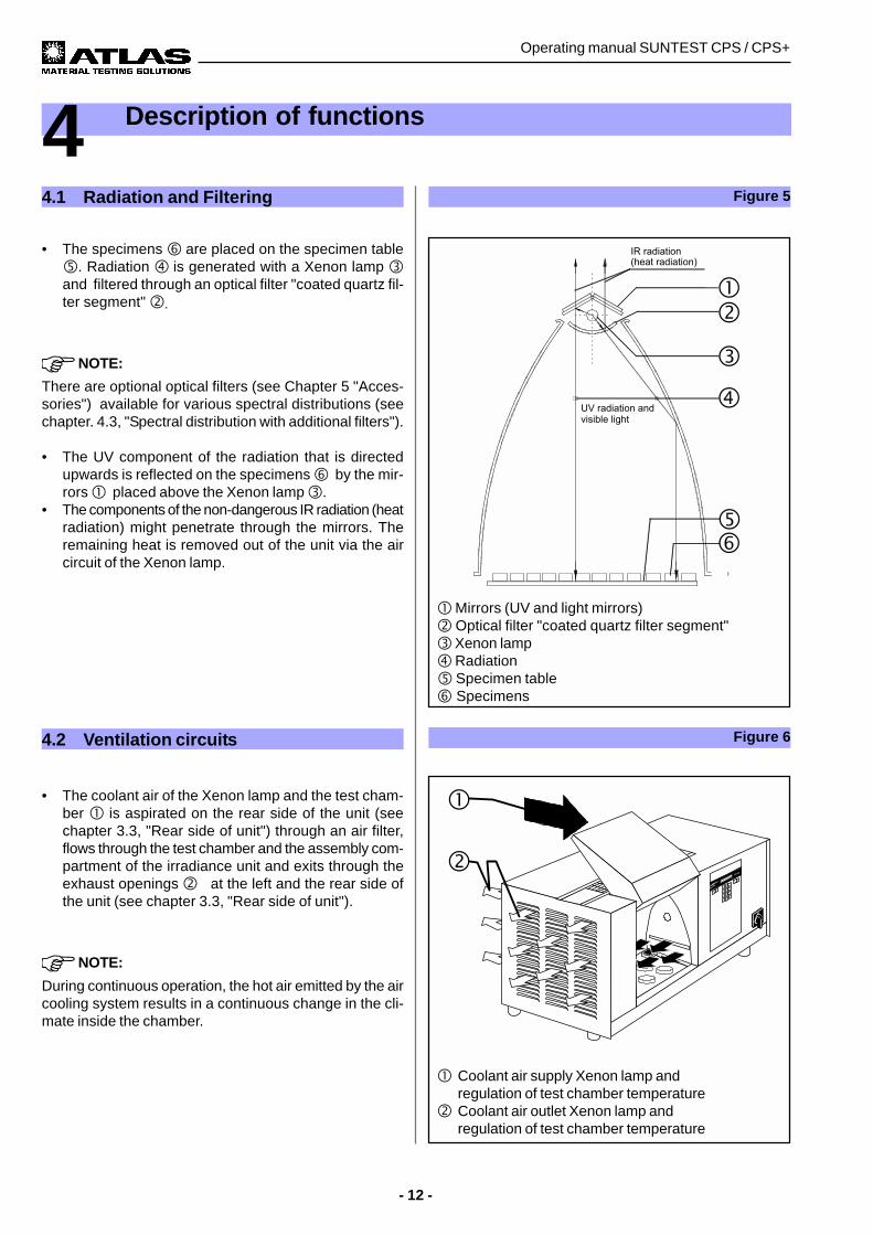
• The specimens & are placed on the specimen table%. Radiation $ is generated with a Xenon lamp #and filtered through an optical filter "coated quartz fil-ter segment" ".
NOTE:
There are optional optical filters (see Chapter 5 "Acces-sories") available for various spectral distributions (seechapter. 4.3, "Spectral distribution with additional filters").
• The UV component of the radiation that is directedupwards is reflected on the specimens & by the mir-rors ! placed above the Xenon lamp #.
• The components of the non-dangerous IR radiation (heatradiation) might penetrate through the mirrors. Theremaining heat is removed out of the unit via the aircircuit of the Xenon lamp.
4 Description of functions
Figure 5
! Coolant air supply Xenon lamp andregulation of test chamber temperature
" Coolant air outlet Xenon lamp andregulation of test chamber temperature
4.1 Radiation and Filtering
4.2 Ventilation circuits
• The coolant air of the Xenon lamp and the test cham-ber ! is aspirated on the rear side of the unit (seechapter 3.3, "Rear side of unit") through an air filter,flows through the test chamber and the assembly com-partment of the irradiance unit and exits through theexhaust openings "(at the left and the rear side ofthe unit (see chapter 3.3, "Rear side of unit").
NOTE:
During continuous operation, the hot air emitted by the aircooling system results in a continuous change in the cli-mate inside the chamber.
Figure 6
! Mirrors (UV and light mirrors)" Optical filter "coated quartz filter segment"# Xenon lamp$ Radiation% Specimen table& Specimens
- 13 -
Operating manual SUNTEST CPS / CPS+
4 Description of functions
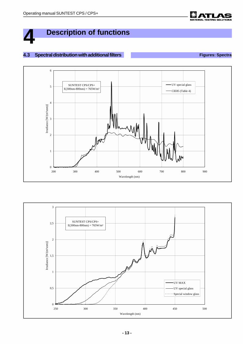
4.3 Spectral distribution with additional filters Figures: Spectra
0
0,5
1
1,5
2
2,5
3
250 300 350 400 450 500
Wavelength (nm)
Irra
dian
ce [
W/(
m²x
nm)]
UV MAX
UV special glass
Special window glass
SUNTEST CPS/CPS+ E(300nm-800nm) = 765W/m²
0
1
2
3
4
5
6
200 300 400 500 600 700 800 900
Wavelength (nm)
Irra
dian
ce [
W/(
m²x
nm)]
UV special glass
CIE85 (Table 4)
SUNTEST CPS/CPS+ E(300nm-800nm) = 765W/m²
Operating manual SUNTEST CPS / CPS+
- 14 -
4 Description of functions
4.4 Sensor system in SUNTEST CPS+
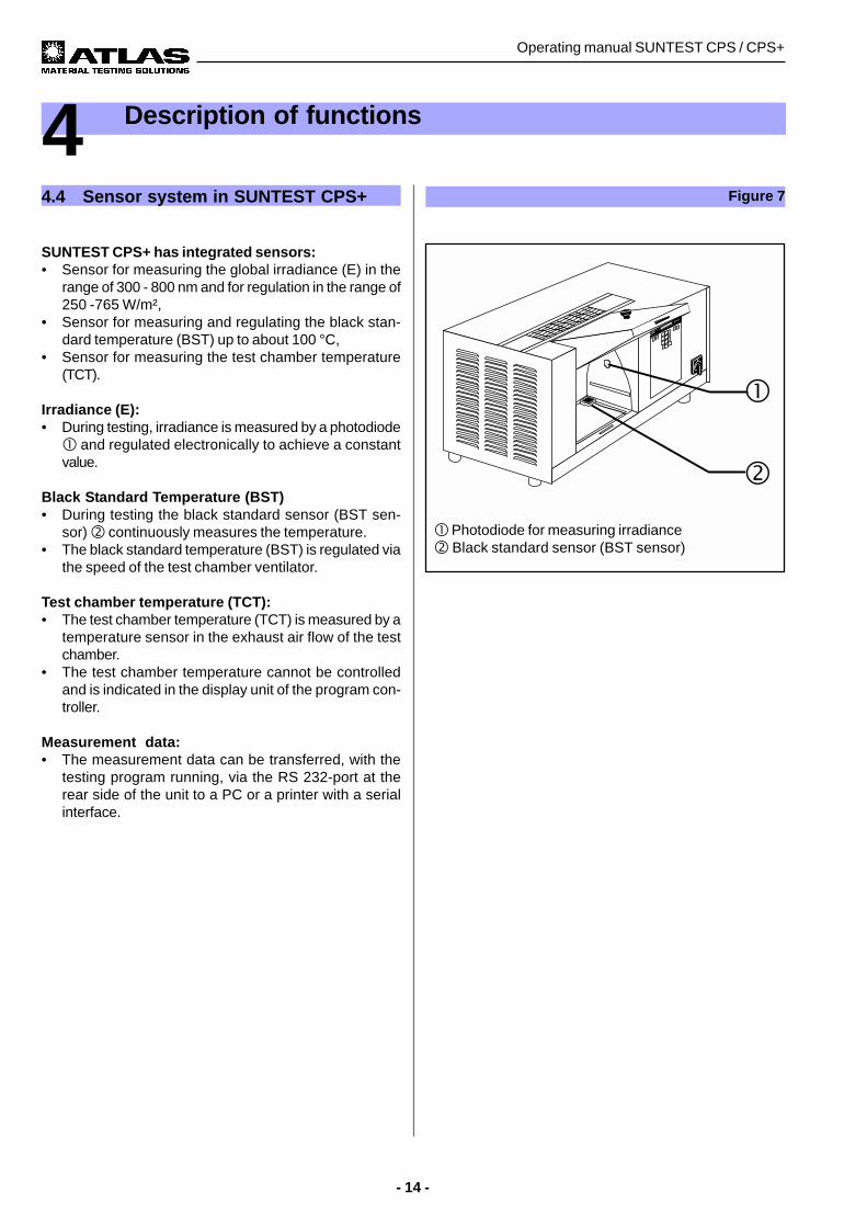
SUNTEST CPS+ has integrated sensors:• Sensor for measuring the global irradiance (E) in the
range of 300 - 800 nm and for regulation in the range of250 -765 W/m²,
• Sensor for measuring and regulating the black stan-dard temperature (BST) up to about 100 °C,
• Sensor for measuring the test chamber temperature(TCT).
Irradiance (E):• During testing, irradiance is measured by a photodiode! and regulated electronically to achieve a constantvalue.
Black Standard Temperature (BST)• During testing the black standard sensor (BST sen-
sor) " continuously measures the temperature.• The black standard temperature (BST) is regulated via
the speed of the test chamber ventilator.
Test chamber temperature (TCT):• The test chamber temperature (TCT) is measured by a
temperature sensor in the exhaust air flow of the testchamber.
• The test chamber temperature cannot be controlledand is indicated in the display unit of the program con-troller.
Measurement data:• The measurement data can be transferred, with the
testing program running, via the RS 232-port at therear side of the unit to a PC or a printer with a serialinterface.
! Photodiode for measuring irradiance" Black standard sensor (BST sensor)
Figure 7
- 15 -
Operating manual SUNTEST CPS / CPS+
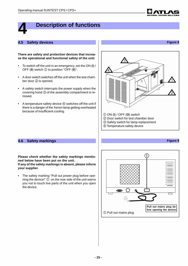
! ON (I) / OFF (O) switch" Door switch for test chamber door# Safety switch for lamp replacement$ Temperature safety device
4 Description of functions
Figure 84.5 Safety devices
There are safety and protection devices that increa-se the operational and functional safety of the unit:
• To switch off the unit in an emergency, set the ON (I) /OFF (0) switch ! to position "OFF (0)".
• A door switch switches off the unit when the test cham-ber door " is opened.
• A safety switch interrupts the power supply when thecovering hood # of the assembly compartment is re-moved.
• A temperature safety device $ switches off the unit ifthere is a danger of the Xenon lamp getting overheatedbecause of insufficient cooling.
Figure 94.6 Safety markings
Please check whether the safety markings mentio-ned below have been put on the unit.If any of the safety markings is absent, please informyour supplier.
• The safety marking "Pull out power plug before ope-ning the device!" ! on the rear side of the unit warnsyou not to touch live parts of the unit when you openthe device.
! Pull out mains plug
Pull out mains plug be-fore opening the device!
Operating manual SUNTEST CPS / CPS+
- 16 -
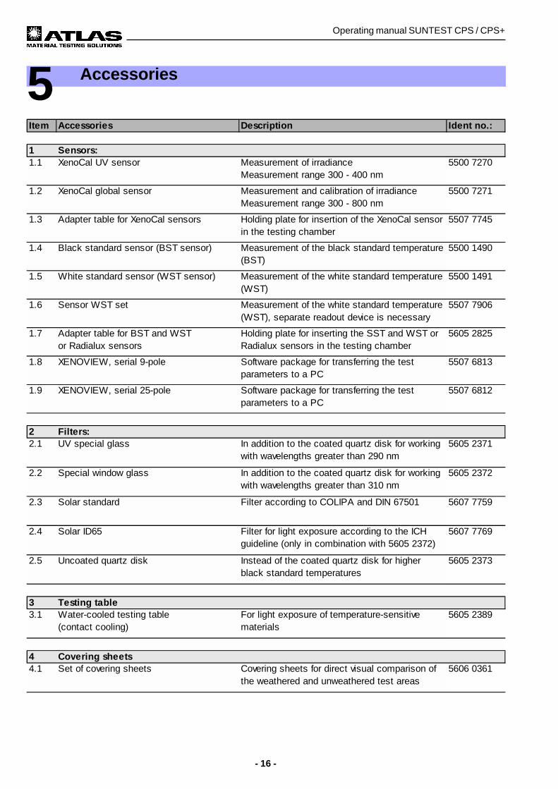
5 Accessories
Item Accessories Description Ident no.:
1 Sensors:1.1 XenoCal UV sensor Measurement of irradiance
Measurement range 300 - 400 nm5500 7270
1.2 XenoCal global sensor Measurement and calibration of irradianceMeasurement range 300 - 800 nm
5500 7271
1.3 Adapter table for XenoCal sensors Holding plate for insertion of the XenoCal sensor in the testing chamber
5507 7745
1.4 Black standard sensor (BST sensor) Measurement of the black standard temperature (BST)
5500 1490
1.5 White standard sensor (WST sensor) Measurement of the white standard temperature (WST)
5500 1491
1.6 Sensor WST set Measurement of the white standard temperature (WST), separate readout device is necessary
5507 7906
1.7 Adapter table for BST and WST or Radialux sensors
Holding plate for inserting the SST and WST or Radialux sensors in the testing chamber
5605 2825
1.8 XENOVIEW, serial 9-pole Software package for transferring the test parameters to a PC
5507 6813
1.9 XENOVIEW, serial 25-pole Software package for transferring the test parameters to a PC
5507 6812
2 Filters:2.1 UV special glass In addition to the coated quartz disk for working
with wavelengths greater than 290 nm5605 2371
2.2 Special window glass In addition to the coated quartz disk for working with wavelengths greater than 310 nm
5605 2372
2.3 Solar standard Filter according to COLIPA and DIN 67501 5607 7759
2.4 Solar ID65 Filter for light exposure according to the ICH guideline (only in combination with 5605 2372)
5607 7769
2.5 Uncoated quartz disk Instead of the coated quartz disk for higher black standard temperatures
5605 2373
3 Testing table3.1 Water-cooled testing table
(contact cooling)For light exposure of temperature-sensitive materials
5605 2389
4 Covering sheets4.1 Set of covering sheets Covering sheets for direct visual comparison of
the weathered and unweathered test areas 5606 0361
- 17 -
Operating manual SUNTEST CPS / CPS+
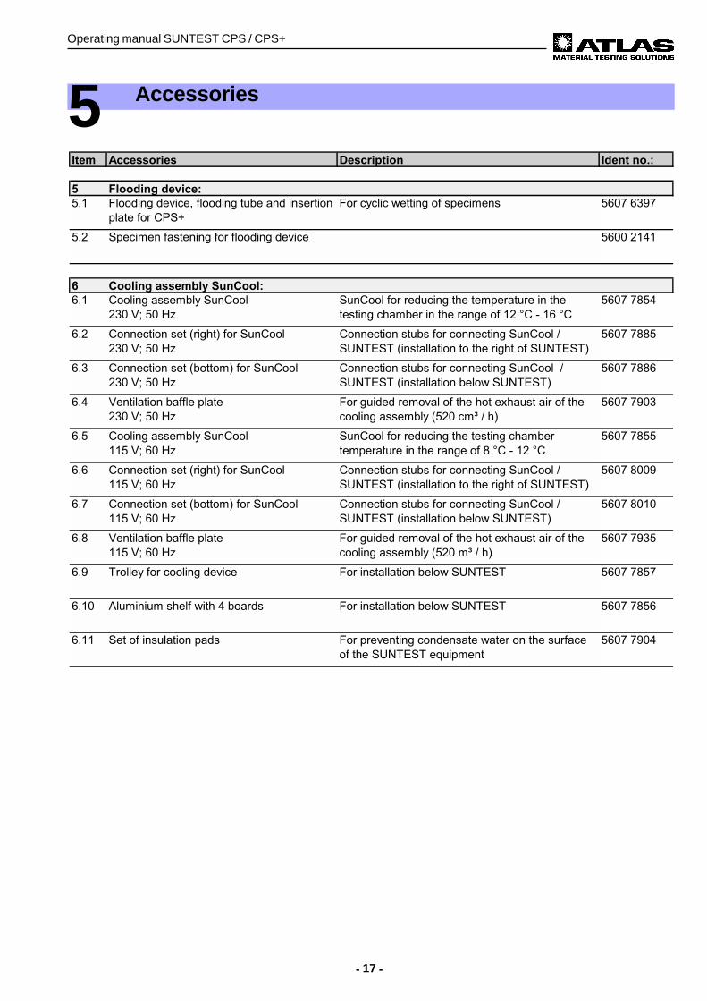
5 Accessories
Operating manual SUNTEST CPS / CPS+
- 18 -
6 Commissioning
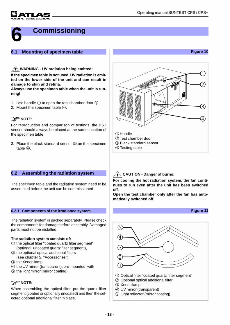
6.1 Mounting of specimen table
WARNING - UV radiation being emitted:
If the specimen table is not used, UV radiation is emit-ted on the lower side of the unit and can result indamage to skin and retina.Always use the specimen table when the unit is run-ning!
1. Use handle ! to open the test chamber door ".2. Mount the specimen table $.
NOTE:
For reproduction and comparison of testings, the BSTsensor should always be placed at the same location ofthe specimen table.
3. Place the black standard sensor # on the specimentable $.
Figure 10
! Handle" Test chamber door# Black standard sensor$ Testing table
! Optical filter "coated quartz filter segment"" Optional optical additional filter# Xenon lamp,$ UV mirror (transparent)% Light reflector (mirror coating)
Figure 116.2.1 Components of the irradiance system
The radiation system is packed separately. Please checkthe components for damage before assembly. Damagedparts must not be installed.
The radiation system consists of:! the optical filter "coated quartz filter segment"
(optional: uncoated quartz filter segment)," the optional optical additional filters
(see chapter 5, "Accessories"),# the Xenon lamp$ the UV mirror (transparent), pre-mounted, with% the light mirror (mirror coating).
NOTE:
When assembling the optical filter, put the quartz filtersegment (coated or optionally uncoated) and then the sel-ected optional additional filter in place.
6.2 Assembling the radiation system
The specimen table and the radiation system need to beassembled before the unit can be commissioned.
CAUTION - Danger of burns:
For cooling the hot radiation system, the fan conti-nues to run even after the unit has been switchedoff.Open the test chamber only after the fan has auto-matically switched off.
- 19 -
Operating manual SUNTEST CPS / CPS+
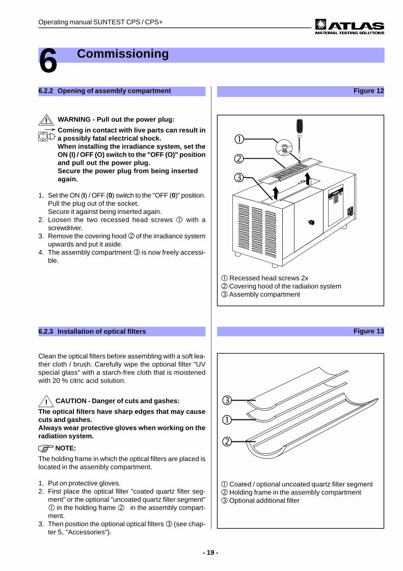
! Recessed head screws 2x" Covering hood of the radiation system# Assembly compartment
Figure 12
6 Commissioning
6.2.2 Opening of assembly compartment
WARNING - Pull out the power plug:
Coming in contact with live parts can result ina possibly fatal electrical shock.When installing the irradiance system, set theON (I) / OFF (O) switch to the "OFF (O)" positionand pull out the power plug.Secure the power plug from being insertedagain.
1. Set the ON (I) / OFF (0) switch to the "OFF (0)" position.Pull the plug out of the socket.Secure it against being inserted again.
2. Loosen the two recessed head screws ! with ascrewdriver.
3. Remove the covering hood " of the irradiance systemupwards and put it aside.
4. The assembly compartment # is now freely accessi-ble.
! Coated / optional uncoated quartz filter segment" Holding frame in the assembly compartment# Optional additional filter
Figure 136.2.3 Installation of optical filters
Clean the optical filters before assembling with a soft lea-ther cloth / brush. Carefully wipe the optional filter "UVspecial glass" with a starch-free cloth that is moistenedwith 20 % citric acid solution.
CAUTION - Danger of cuts and gashes:
The optical filters have sharp edges that may causecuts and gashes.Always wear protective gloves when working on theradiation system.
NOTE:
The holding frame in which the optical filters are placed islocated in the assembly compartment.
1. Put on protective gloves.2. First place the optical filter "coated quartz filter seg-
ment" or the optional "uncoated quartz filter segment"! in the holding frame "(in the assembly compart-ment.
3. Then position the optional optical filters # (see chap-ter 5, "Accessories").
Operating manual SUNTEST CPS / CPS+
- 20 -
6 Commissioning
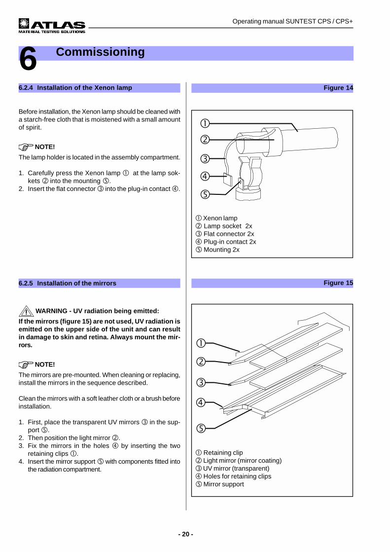
! Xenon lamp" Lamp socket 2x# Flat connector 2x$ Plug-in contact 2x% Mounting 2x
Figure 14
! Retaining clip" Light mirror (mirror coating)# UV mirror (transparent)$ Holes for retaining clips% Mirror support
Figure 156.2.5 Installation of the mirrors
WARNING - UV radiation being emitted:
If the mirrors (figure 15) are not used, UV radiation isemitted on the upper side of the unit and can resultin damage to skin and retina. Always mount the mir-rors.
NOTE!
The mirrors are pre-mounted. When cleaning or replacing,install the mirrors in the sequence described.
Clean the mirrors with a soft leather cloth or a brush beforeinstallation.
1. First, place the transparent UV mirrors # in the sup-port %.
2. Then position the light mirror ".3. Fix the mirrors in the holes $ by inserting the two
retaining clips !.4. Insert the mirror support % with components fitted into
the radiation compartment.
6.2.4 Installation of the Xenon lamp
Before installation, the Xenon lamp should be cleaned witha starch-free cloth that is moistened with a small amountof spirit.
NOTE!
The lamp holder is located in the assembly compartment.
1. Carefully press the Xenon lamp ! at the lamp sok-kets " into the mounting %.
2. Insert the flat connector # into the plug-in contact $.
- 21 -
Operating manual SUNTEST CPS / CPS+
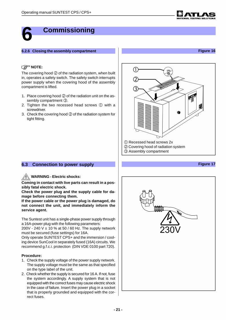
! Recessed head screws 2x" Covering hood of radiation system# Assembly compartment
6 Commissioning
Figure 166.2.6 Closing the assembly compartment
NOTE:
The covering hood " of the radiation system, when builtin, operates a safety switch. The safety switch interruptspower supply when the covering hood of the assemblycompartment is lifted.
1. Place covering hood " of the radiation unit on the as-sembly compartment #.
2. Tighten the two recessed head screws ! with ascrewdriver.
3. Check the covering hood " of the radiation system fortight fitting.
6.3 Connection to power supply
WARNING - Electric shocks:
Coming in contact with live parts can result in a pos-sibly fatal electric shock.Check the power plug and the supply cable for da-mage before connecting them.If the power cable or the power plug is damaged, donot connect the unit, and immediately inform theservice agent.
The Suntest unit has a single-phase power supply througha 16A-power plug with the following parameters:200V - 240 V ± 10 % at 50 / 60 Hz. The supply networkmust be secured (fuse settings) for 16A.Only operate SUNTEST CPS+ and the immersion / cool-ing device SunCool in separately fused (16A) circuits. Werecommend g.f.c.i. protection (DIN VDE 0100 part 720).
Procedure:1. Check the supply voltage of the power supply network.
The supply voltage must be the same as that specifiedon the type label of the unit.
2. Check whether the supply is secured for 16 A. If not, fusethe system accordingly. A supply system that is notequipped with the correct fuses may cause electric shockin the case of failure. Insert the power plug in a socketthat is properly grounded and equipped with the cor-rect fuses.
Figure 17
Operating manual SUNTEST CPS / CPS+
- 22 -
7.3 Testing procedure with optional unit
Various accessories are available to enhance thecapacities of SUNTEST CPS / CPS+ (see chapter 5,"Accessories").
• For temperature-sensitive materials:Watercooled specimen table with water hose for con-nection to the water drains.
• Cover masks:For a direct visual comparison between exposed andnon-exposed specimen surfaces.
• Cooling assembly SunCool:For reducing the test chamber temperature in the ran-ge of 8 °C - 12 °C in the SUNTEST CPS+ and 12 °C -16 °C in the SUNTEST CPS.
• Immersion device:For cyclic wetting of specimens.
7 Operation and Shutdown
7.1 Configuration of unit
WARNING - Pull out the power plug:
Coming in contact with live parts can result ina fatal electrical shock.For the configuration of the unit, set the ON (I)/ OFF (0) switch to the "OFF (0)" position andpull out the power plug. Secure the power plugagainst being inserted again.
1. Set the ON (I) / OFF (0) switch to the "OFF (0)" position.Pull the power plug out of the power socket.Secure the power plug against being inserted again.
2. Use the specimen table as described in chapter 6 "Com-missioning".
3. Insert the optical filter, the Xenon lamp and the mirrorsas described in chapter 6 "Commissioning".
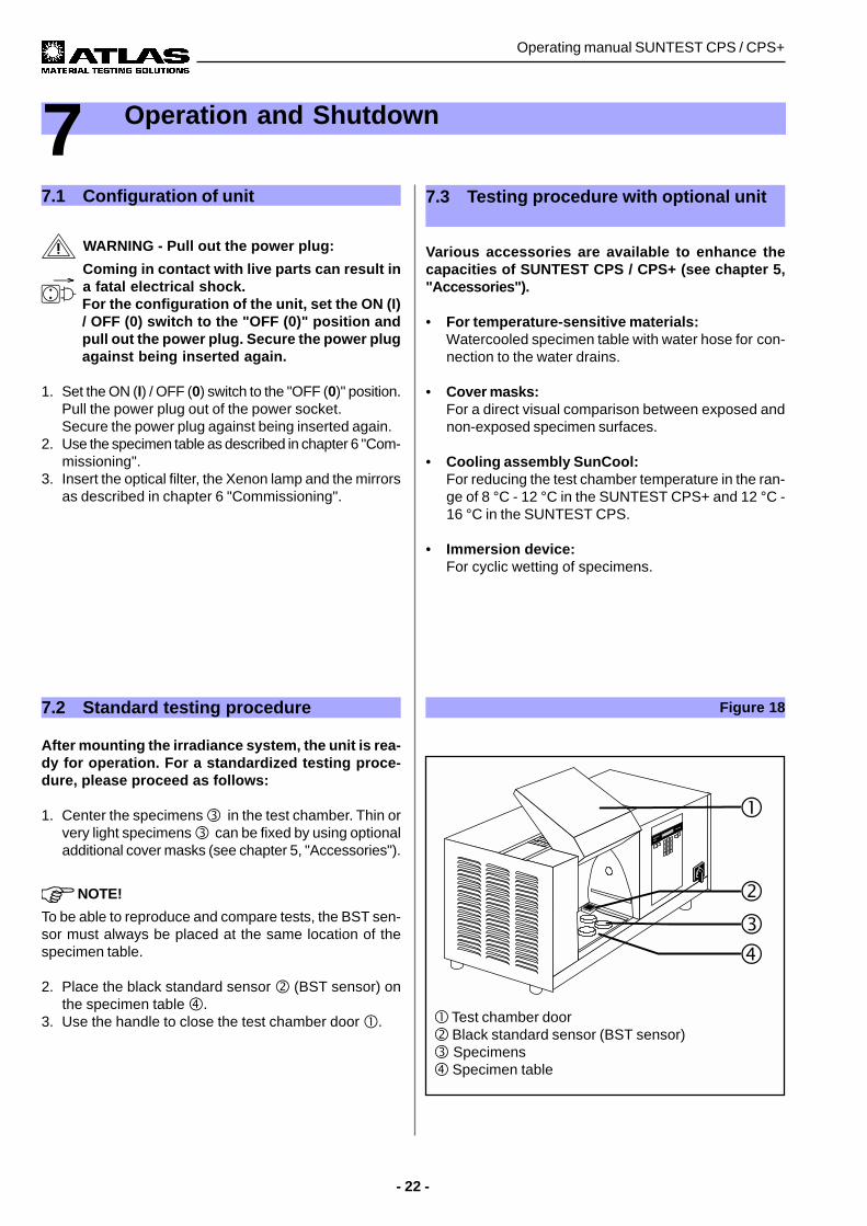
! Test chamber door" Black standard sensor (BST sensor)# Specimens$ Specimen table
7.2 Standard testing procedure
After mounting the irradiance system, the unit is rea-dy for operation. For a standardized testing proce-dure, please proceed as follows:
1. Center the specimens # in the test chamber. Thin orvery light specimens # can be fixed by using optionaladditional cover masks (see chapter 5, "Accessories").
NOTE!
To be able to reproduce and compare tests, the BST sen-sor must always be placed at the same location of thespecimen table.
2. Place the black standard sensor " (BST sensor) onthe specimen table $.
3. Use the handle to close the test chamber door !.
Figure 18
- 23 -
Operating manual SUNTEST CPS / CPS+
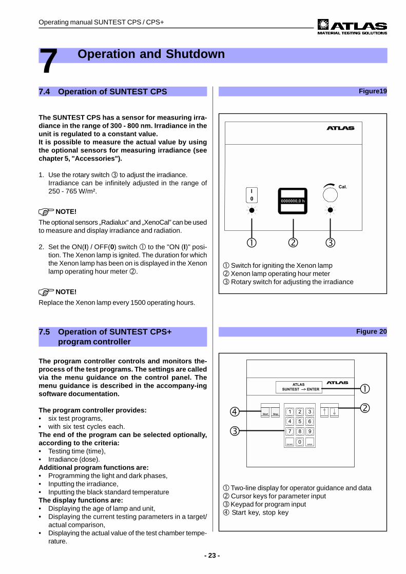
Figure19
7 Operation and Shutdown
! Switch for igniting the Xenon lamp" Xenon lamp operating hour meter# Rotary switch for adjusting the irradiance
7.4 Operation of SUNTEST CPS
The SUNTEST CPS has a sensor for measuring irra-diance in the range of 300 - 800 nm. Irradiance in theunit is regulated to a constant value.It is possible to measure the actual value by usingthe optional sensors for measuring irradiance (seechapter 5, "Accessories").
1. Use the rotary switch # to adjust the irradiance.Irradiance can be infinitely adjusted in the range of250 - 765 W/m².
NOTE!
The optional sensors „Radialux“ and „XenoCal” can be usedto measure and display irradiance and radiation.
2. Set the ON(I) / OFF(0) switch ! to the "ON (I)" posi-tion. The Xenon lamp is ignited. The duration for whichthe Xenon lamp has been on is displayed in the Xenonlamp operating hour meter ".
NOTE!
Replace the Xenon lamp every 1500 operating hours.
! Two-line display for operator guidance and data" Cursor keys for parameter input# Keypad for program input$ Start key, stop key
Figure 207.5 Operation of SUNTEST CPS+program controller
The program controller controls and monitors the-process of the test programs. The settings are calledvia the menu guidance on the control panel. Themenu guidance is described in the accompany-ingsoftware documentation.
The program controller provides:• six test programs,• with six test cycles each.The end of the program can be selected optionally,according to the criteria:• Testing time (time),• Irradiance (dose).Additional program functions are:• Programming the light and dark phases,• Inputting the irradiance,• Inputting the black standard temperatureThe display functions are:• Displaying the age of lamp and unit,• Displaying the current testing parameters in a target/
actual comparison,• Displaying the actual value of the test chamber tempe-
rature.
Operating manual SUNTEST CPS / CPS+
- 24 -
7.7 Shutdown
CAUTION - Danger of burns:
For cooling the hot specimens and the specimenholders, the fan continues to run even after the unithas been switched off.Open the test chamber only after the fan has auto-matically switched off.When replacing specimens, wear protective gloves.
1. After the fan is switched off automatically, set the ON(I) / OFF (0) switch to the "OFF (0)" position.
2. Put on protective gloves.3. Open the test chamber door using the handle and re-
move the specimens from the test chamber.4. If required, remove additional optional accessories from
the test chamber.5. Clean the unit according to chapter 9.1, "Cleaning".6. During longer interruptions of operation pull out the
power plug as well.
7 Operation and Shutdown
Figure 217.6 Data transfer to a PC
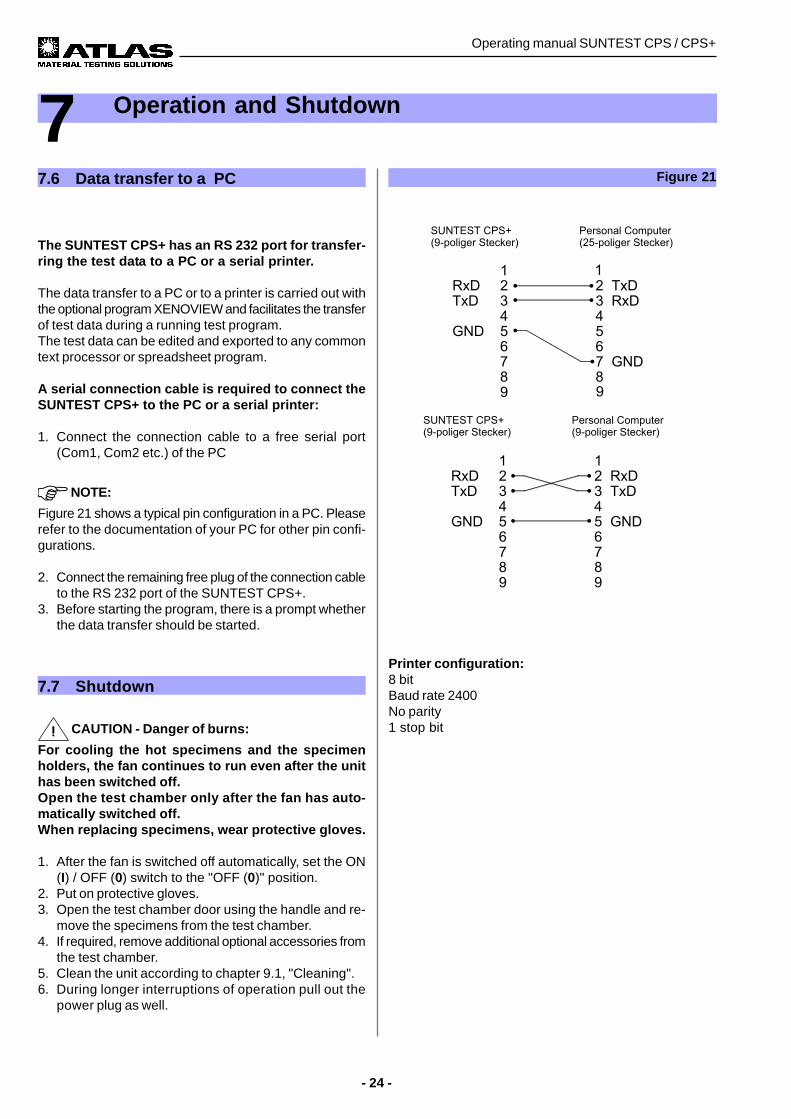
The SUNTEST CPS+ has an RS 232 port for transfer-ring the test data to a PC or a serial printer.
The data transfer to a PC or to a printer is carried out withthe optional program XENOVIEW and facilitates the transferof test data during a running test program.The test data can be edited and exported to any commontext processor or spreadsheet program.
A serial connection cable is required to connect theSUNTEST CPS+ to the PC or a serial printer:
1. Connect the connection cable to a free serial port(Com1, Com2 etc.) of the PC
NOTE:
Figure 21 shows a typical pin configuration in a PC. Pleaserefer to the documentation of your PC for other pin confi-gurations.
2. Connect the remaining free plug of the connection cableto the RS 232 port of the SUNTEST CPS+.
3. Before starting the program, there is a prompt whetherthe data transfer should be started.
Printer configuration:8 bitBaud rate 2400No parity1 stop bit
- 25 -
Operating manual SUNTEST CPS / CPS+
8 Calibration
Abbildung 228.1 Calibration of irradiance with theXenoCal Global Sensor
NOTE:
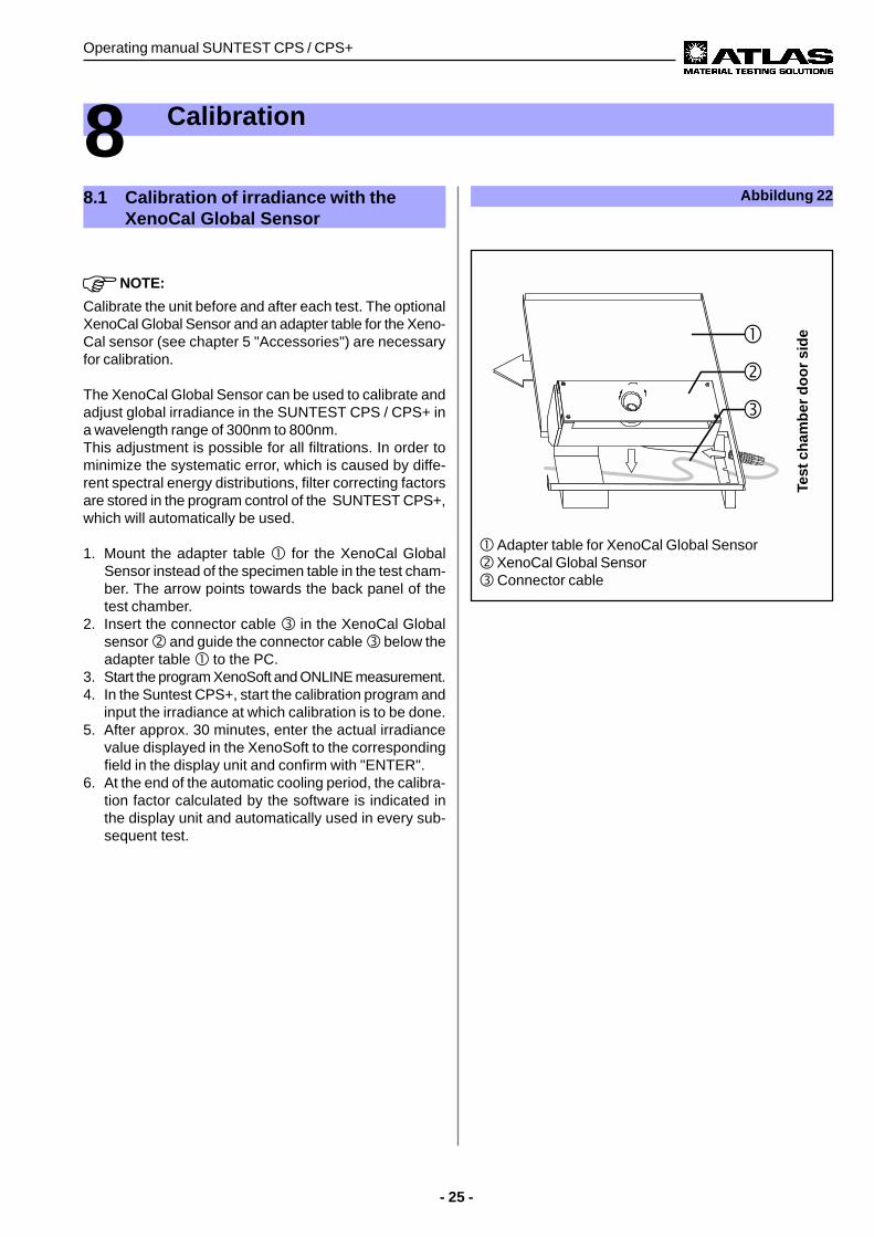
Calibrate the unit before and after each test. The optionalXenoCal Global Sensor and an adapter table for the Xeno-Cal sensor (see chapter 5 "Accessories") are necessaryfor calibration.
The XenoCal Global Sensor can be used to calibrate andadjust global irradiance in the SUNTEST CPS / CPS+ ina wavelength range of 300nm to 800nm.This adjustment is possible for all filtrations. In order tominimize the systematic error, which is caused by diffe-rent spectral energy distributions, filter correcting factorsare stored in the program control of the SUNTEST CPS+,which will automatically be used.
1. Mount the adapter table ! for the XenoCal GlobalSensor instead of the specimen table in the test cham-ber. The arrow points towards the back panel of thetest chamber.
2. Insert the connector cable # in the XenoCal Globalsensor " and guide the connector cable # below theadapter table ! to the PC.
3. Start the program XenoSoft and ONLINE measurement.4. In the Suntest CPS+, start the calibration program and
input the irradiance at which calibration is to be done.5. After approx. 30 minutes, enter the actual irradiance
value displayed in the XenoSoft to the correspondingfield in the display unit and confirm with "ENTER".
6. At the end of the automatic cooling period, the calibra-tion factor calculated by the software is indicated inthe display unit and automatically used in every sub-sequent test.
! Adapter table for XenoCal Global Sensor" XenoCal Global Sensor# Connector cable
Test
ch
amb
er d
oo
r si
de
Operating manual SUNTEST CPS / CPS+
- 26 -
Figure 23
8 Calibration
8.2 Calibration of irradiance with theRadialux Global Sensor
NOTE:
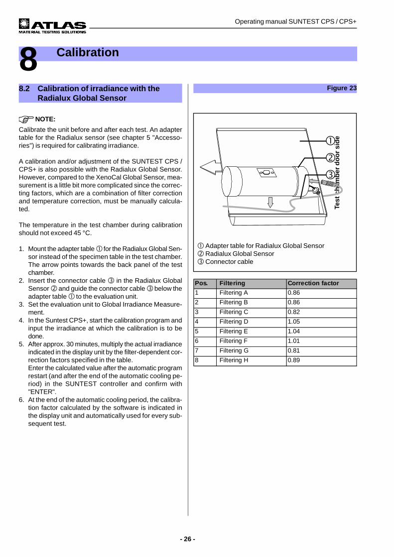
Calibrate the unit before and after each test. An adaptertable for the Radialux sensor (see chapter 5 "Accesso-ries") is required for calibrating irradiance.
A calibration and/or adjustment of the SUNTEST CPS /CPS+ is also possible with the Radialux Global Sensor.However, compared to the XenoCal Global Sensor, mea-surement is a little bit more complicated since the correc-ting factors, which are a combination of filter correctionand temperature correction, must be manually calcula-ted.
The temperature in the test chamber during calibrationshould not exceed 45 °C.
1. Mount the adapter table ! for the Radialux Global Sen-sor instead of the specimen table in the test chamber.The arrow points towards the back panel of the testchamber.
2. Insert the connector cable # in the Radialux GlobalSensor " and guide the connector cable # below theadapter table ! to the evaluation unit.
3. Set the evaluation unit to Global Irradiance Measure-ment.
4. In the Suntest CPS+, start the calibration program andinput the irradiance at which the calibration is to bedone.
5. After approx. 30 minutes, multiply the actual irradianceindicated in the display unit by the filter-dependent cor-rection factors specified in the table.Enter the calculated value after the automatic programrestart (and after the end of the automatic cooling pe-riod) in the SUNTEST controller and confirm with"ENTER".
6. At the end of the automatic cooling period, the calibra-tion factor calculated by the software is indicated inthe display unit and automatically used for every sub-sequent test.
! Adapter table for Radialux Global Sensor" Radialux Global Sensor# Connector cable
Pos. Filtering Correction factor
1 Filtering A 0.86
2 Filtering B 0.86
3 Filtering C 0.82
4 Filtering D 1.05
5 Filtering E 1.04
6 Filtering F 1.01
7 Filtering G 0.81
8 Filtering H 0.89
Test
ch
amb
er d
oo
r si
de

- 27 -
Operating manual SUNTEST CPS / CPS+
8 Calibration
8.3 Calibration of the black standard tem-perature
NOTE:
Calibrate the unit before and after every test. An optionalblack standard thermometer and a corresponding adapter(see chapter 5 "Accessories") are necessary for calibra-ting the black standard temperature.
1. Use the adapter table ! for the black standard ther-mometer instead of the specimen table in the testchamber. The arrow points towards the back panel ofthe test chamber.
2. The external black standard thermometer # shouldbe placed in such a way that the black surface pointsupwards, i.e. towards the Xenon lamp.
3. In the SUNTEST CPS+, start the calibration programand enter the desired black standard temperaturevalue at the desired irradiance value.
CAUTION - Danger of burns:
The black standard thermometer can be very hot af-ter a measurement has been taken.When reading or removing the black standard ther-mometer from the test chamber, it may be necessaryto wear protective gloves!
4. If required, put on protective gloves.5. After approx. 60 minutes, interrupt the program with
"STOP", turn the black standard thermometer aroundand immediately read the temperature in the display ofthe black standard thermometer.
6. Enter the read-off temperature value (after the automa-tic cooling period) in the SUNTEST controller and con-firm with "ENTER".
7. The calibration factor calculated by the software is in-dicated in the SUNTEST display and, after confirmati-on by "ENTER", automatically used in each subse-quent test.
Figure 24
! Adapter table for black standard thermometer" Black standard thermometer
Test
ch
amb
er d
oo
r si
de
Operating manual SUNTEST CPS / CPS+
- 28 -
9.1.3 Radiation system
The components of the radiation system must be cleanedat least every six months. The irradiance system must bedisassembled in the opposite sequence to that describedin chapter 6.2, "Assembling the irradiance system".
Optical filters:• Clean the optical filters with a soft leather cloth or brush
before installing them.• Carefully wipe the optional filter "UV special glass" with
a starchless cloth that has been moistened with 20 %citric acid solution.
Xenon lamp:• Clean the cold Xenon lamp with a starch-free cloth that
is moistened with some spirit.
Mirrors:• Clean the mirrors, before mounting, with a soft leather
cloth or a brush.
9.1.4 Air filter
CAUTION - Damage to the unit:
The reflector and the radiation system are sensitiveto dust. Unfiltered cooling air will adversely affectthe functioning of the unit.The air filters must be cleaned every six months.The air filters must always be installed during ope-ration.
Procedure:• Remove the filter mat from the filter opening on the
rear side of the unit.• Beat the dirty filter mat or wash it with lukewarm water
and some mild soap solution (washing liquid).If the filter mat is particularly dirty, replace it (for ident.no., see chapter 9.2, "Spare parts").
• Let the filter mat dry and re-insert it in the filter openingwith the soft layer on the outside.
9 Cleaning / Consumables
9.1 Cleaning
WARNING - Pull out the power plug:
Coming in contact with live parts can result ina fatal electric shock. For all cleaning work,set the ON (I) / OFF (0) switch to the “OFF (0)”position and pull out the power plug. Securethe power plug against getting inserted again.
9.1.1 Outer surfaces and operating elements
Wipe the unit with a mild soap solution (washing agent)and a soft cloth.
9.1.2 Reflector
To ensure uniform illumination of the test chamber, thereflector has to be kept clean.
CAUTION - Damage to the reflector:
The reflecting coating of the test chamber walls issensitive to scratches.Do not use any solvents, or any rough or hard clean-ing agents for cleaning the reflector.
Procedure:• Wipe the reflector with a soft cloth that has been moi-
stened with the usual commercially available washingagents and rub dry till it is free from streaks.
- 29 -
Operating manual SUNTEST CPS / CPS+
9 Cleaning / Consumables
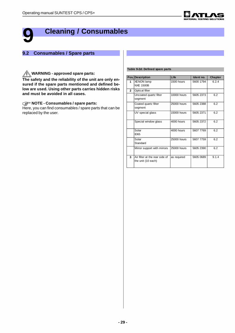
9.2 Consumables / Spare parts
Table 9-2d: Defined spare parts
Pos. Description Life Ident no. Chapter
1 XENON lamp NXE 1500B
1500 hours 5600 1794 6.2.4
2 Optical filter
Uncoated quartz filter segment
10000 hours 5605 2373 6.2
Coated quartz filter segment
25000 hours 5605 2388 6.2
UV special glass 15000 hours 5605 2371 6.2
Special window glass 4000 hours 5605 2372 6.2
Solar ID65
4000 hours 5607 7769 6.2
Solar Standard
25000 hours 5607 7759 6.2
Mirror support with mirrors 25000 hours 5605 2390 6.2
3 Air filter at the rear side of the unit (10 each)
as required 5605 0689 9.1.4
WARNING - approved spare parts:
The safety and the reliability of the unit are only en-sured if the spare parts mentioned and defined be-low are used. Using other parts carries hidden risksand must be avoided in all cases.
NOTE - Consumables / spare parts:Here, you can find consumables / spare parts that can bereplaced by the user.
Operating manual SUNTEST CPS / CPS+
- 30 -
10 Maintenance
10.1 Maintenance and care
At least once a year, it is necessary to ensure that thefollowing systems are in proper condition:
• Mechanical system• Functions (Technical Data)• Electrical system (FRG: UVV VGB 4)• Safety devices of the unit
If protective devices have been dismantled or disabled formaintenance work, do not restart the unit before the pro-tective devices have been reinstalled and their properfunctioning has been checked.
NOTE - Guarantee:
The manufacturer guarantees the safety and properfunctioning of the unit only provided that:
• the maintenance intervals are adhered to• all maintenance work is carried out by trained and
suitably qualified personnel,• only original spare parts are used.
ATLAS provides a customized service package forthis unit, consisting of a maintenance, measurementand calibration service, that ensures the efficiencyand process safety of the unit.
10.2 Commissioning
NOTES - Spare parts:We will provide a complete list of spare parts as well asother documentation on request to suitably trained andqualified personnel.
- 31 -
Operating manual SUNTEST CPS / CPS+
SUNTEST CPS / CPS+
Power supply:
Supply voltage: 200-240 V ± 10 %, 50/60 HzSupply connection: CEE (16A, 3-pole, 6h) (1, N, PE)
Amperage: max. 14.5 A
Fuse rating: 16 A
Power consumption: max. 2.1 kVA
Nominal rating of max. 1.5 KWXenon lamp
Cooling requirements:
Lamp cooling 150 m³/hAir conditioner min. 60 m³/h, max. 150 m³/h
Dimensions and weight:
Dimensions in cm: 78 x 35 x 35(width x depth x height)Specimen table: 28 x 20 cmSpecimen surface area: approx. 500 cm²Weight: approx. 30 kg
Noise emission:
Noise level: max. 70 dB (A)
Ambient conditions:
Room temperature: 18 °C to 25 °C
Relative humidity: approx. 70 %
Air pressure: 700 - 1060 hPa
11 Technical Data
ATLAS Material Testing Technology GmbHVogelsbergstr. 22D-63589 Linsengericht / AltenhaßlauPhone: + 49/6051/707-140Fax: + 49/6051/707-149Ident no.: 56350025 04.00


![18-4masglp.olemiss.edu/Water Log PDF/18-4.pdfcob-qoza_T ZApg1J cg1crqgg1JB cps cps aorupgw glgccgq co nag g rg4 cps cps g aorupgw co pgbgug]lxgq upla ÀggL' cps cowbg1JÀ pgcaug cps](https://img.dokumen.tips/doc/110x75/5e2f59f63318b957b5481e92/18-log-pdf18-4pdf-cob-qozat-zapg1j-cg1crqgg1jb-cps-cps-aorupgw-glgccgq-co-nag.jpg)