Embed Size (px)
Citation preview

TEAL PN 1060147 | Models Multigate XT1 to XT4 | Revision 2.5
SUNNY MULTIGATE XTInstallation Manual
US
Designed and Manufactured by TEAL Electronics
Installation Manual - TEAL PN 1060147 rev 2.52
TEAL Electronics SMA America, LLC
Installation Manual - TEAL PN 1060147 rev 2.5 3
TEAL Electronics SMA America, LLC
Copyright © 2013 TEAL Electronics. All rights reserved. Some portions of this document are protected under Copyright © 2012 and 2013 SMA America, LLC. All rights reserved.No part of this document may be reproduced, stored in a retrieval system, or transmitted, in any form or by any means, electronic, mechanical, photographic, magnetic or otherwise, without the prior written permission of SMA America, LLC and TEAL Electronics.Neither SMA America, LLC nor TEAL Electronics makes representations, express or implied, with respect to this documentation or any of the equipment and/or software it may describe, including (with no limitation) any implied warranties of utility, merchantability, or fitness for any particular purpose. All such warranties are expressly disclaimed. Neither SMA America, LLC nor its distributors or dealers nor TEAL Electronics nor its distributors or dealers shall be liable for any indirect, incidental, or consequential damages under any circumstances.(The exclusion of implied warranties may not apply in all cases under some statutes, and thus the above exclusion may not apply.)Specifications are subject to change without notice. Every attempt has been made to make this document complete, accurate and up-to-date. Readers are cautioned, however, that SMA America, LLC and TEAL Electronics reserve the right to make changes without notice and shall not be responsible for any damages, including indirect, incidental or consequential damages, caused by reliance on the material presented, including, but not limited to, omissions, typographical errors, arithmetical errors or listing errors in the content material.All trademarks are recognized even if these are not marked separately. Missing designations do not mean that a product or brand is not a registered trademark.
SMA America, LLC3801 N. Havana Street
Denver, CO 80239 U.S.A.
TEAL Electronics10350 Sorrento Valley Road
San Diego, CA 92121 U.S.A.
Installation Manual - TEAL PN 1060147 rev 2.54
TEAL Electronics SMA America, LLC
IMPORTANT SAFETY INSTRUCTIONSSAVE THESE INSTRUCTIONSThis manual contains important instructions for the Multigate XT enclosure product family.
This manual must be followed during installation and maintenance.
The products are designed and tested according to international safety requirements, but as with all electrical and electronic equipment, certain precautions must be observed when installing and/or operating the products. To reduce the risk of personal injury and to ensure the safe installation and operation of the products, you must carefully read and follow all instructions, cautions and warnings in this manual.
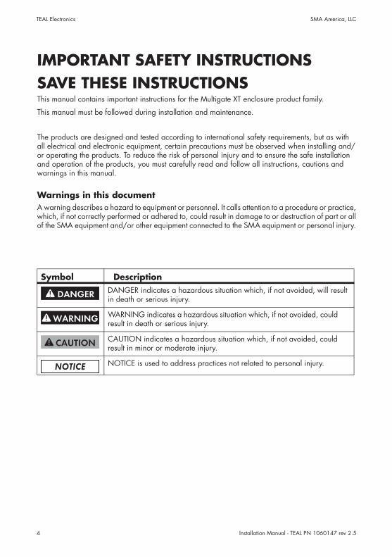
Warnings in this documentA warning describes a hazard to equipment or personnel. It calls attention to a procedure or practice, which, if not correctly performed or adhered to, could result in damage to or destruction of part or all of the SMA equipment and/or other equipment connected to the SMA equipment or personal injury.
Symbol DescriptionDANGER indicates a hazardous situation which, if not avoided, will result in death or serious injury.
WARNING indicates a hazardous situation which, if not avoided, could result in death or serious injury.
CAUTION indicates a hazardous situation which, if not avoided, could result in minor or moderate injury.
NOTICE is used to address practices not related to personal injury.
Installation Manual - TEAL PN 1060147 rev 2.5 5
TEAL Electronics SMA America, LLC
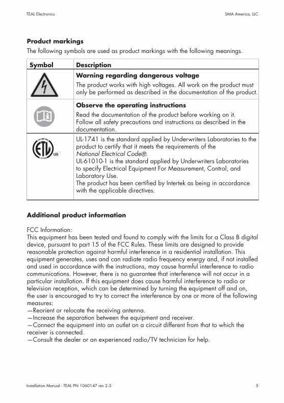
Product markingsThe following symbols are used as product markings with the following meanings.
Symbol Description
Warning regarding dangerous voltageThe product works with high voltages. All work on the product must only be performed as described in the documentation of the product.
Observe the operating instructionsRead the documentation of the product before working on it. Follow all safety precautions and instructions as described in the documentation.UL-1741 is the standard applied by Underwriters Laboratories to the product to certify that it meets the requirements of the National Electrical Code®. UL-61010-1 is the standard applied by Underwriters Laboratories to specify Electrical Equipment For Measurement, Control, and Laboratory Use. The product has been certified by Intertek as being in accordance with the applicable directives.
FCC Information:This equipment has been tested and found to comply with the limits for a Class B digital device, pursuant to part 15 of the FCC Rules. These limits are designed to provide reasonable protection against harmful interference in a residential installation. This equipment generates, uses and can radiate radio frequency energy and, if not installed and used in accordance with the instructions, may cause harmful interference to radio communications. However, there is no guarantee that interference will not occur in a particular installation. If this equipment does cause harmful interference to radio or television reception, which can be determined by turning the equipment off and on, the user is encouraged to try to correct the interference by one or more of the following measures:—Reorient or relocate the receiving antenna.—Increase the separation between the equipment and receiver.—Connect the equipment into an outlet on a circuit different from that to which the receiver is connected.—Consult the dealer or an experienced radio/TV technician for help.
Additional product information
Installation Manual - TEAL PN 1060147 rev 2.56
TEAL Electronics SMA America, LLC
General Warnings
General WarningsAll electrical installations must be done in accordance with the local and National Electrical Code® or ANSI/NFPA 70. This document does not and is not intended to replace any local, state, provincial, federal or national laws, regulation or codes applicable to the installation and use of the product, including without limitation applicable electrical safety codes. All installations must conform with the laws, regulations, codes and standards applicable in the jurisdiction of installation. Neither SMA nor TEAL assumes responsibility for the compliance or noncompliance with such laws or codes in connection with the installation of the product.The product contains no user-serviceable parts. For all repair and maintenance, always contact an authorized SMA Service Center.Before installing or using the product, read all of the instructions, cautions, and warnings in this manual.Before connecting the product to the electrical utility grid, contact the local utility company. This connection must be made only by qualified personnel.
Wiring of the product must be made by qualified personnel only.
Installation Manual - TEAL PN 1060147 rev 2.5 7
TEAL Electronics SMA America, LLC
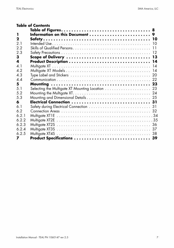
Table of ContentsTable of Figures. . . . . . . . . . . . . . . . . . . . . . . . . . . . . . . . . . . 8
1 Information on this Document . . . . . . . . . . . . . . . . . . . . . . . . 92 Safety . . . . . . . . . . . . . . . . . . . . . . . . . . . . . . . . . . . . . . . . . . 102.1 Intended Use . . . . . . . . . . . . . . . . . . . . . . . . . . . . . . . . . . . . . . . . . . . 102.2 Skills of Qualified Persons . . . . . . . . . . . . . . . . . . . . . . . . . . . . . . . . . . 112.3 Safety Precautions . . . . . . . . . . . . . . . . . . . . . . . . . . . . . . . . . . . . . . . 123 Scope of Delivery . . . . . . . . . . . . . . . . . . . . . . . . . . . . . . . . . 134 Product Description . . . . . . . . . . . . . . . . . . . . . . . . . . . . . . . . 144.1 Multigate XT . . . . . . . . . . . . . . . . . . . . . . . . . . . . . . . . . . . . . . . . . . . 144.2 Multigate XT Models . . . . . . . . . . . . . . . . . . . . . . . . . . . . . . . . . . . . . 144.3 Type Label and Stickers . . . . . . . . . . . . . . . . . . . . . . . . . . . . . . . . . . . 204.4 Communication . . . . . . . . . . . . . . . . . . . . . . . . . . . . . . . . . . . . . . . . . 225 Mounting . . . . . . . . . . . . . . . . . . . . . . . . . . . . . . . . . . . . . . . 235.1 Selecting the Multigate XT Mounting Location . . . . . . . . . . . . . . . . . . . . 235.2 Mounting the Multigate XT. . . . . . . . . . . . . . . . . . . . . . . . . . . . . . . . . . 245.3 Mounting and Dimensional Details . . . . . . . . . . . . . . . . . . . . . . . . . . . . 256 Electrical Connection . . . . . . . . . . . . . . . . . . . . . . . . . . . . . . . 316.1 Safety during Electrical Connection . . . . . . . . . . . . . . . . . . . . . . . . . . . 316.2 Connection Areas . . . . . . . . . . . . . . . . . . . . . . . . . . . . . . . . . . . . . . . 326.2.1 Multigate XT1E . . . . . . . . . . . . . . . . . . . . . . . . . . . . . . . . . . . . . . . . . . 346.2.2 Multigate XT2E . . . . . . . . . . . . . . . . . . . . . . . . . . . . . . . . . . . . . . . . . . 356.2.3 Multigate XT2S . . . . . . . . . . . . . . . . . . . . . . . . . . . . . . . . . . . . . . . . . 366.2.4 Multigate XT3S . . . . . . . . . . . . . . . . . . . . . . . . . . . . . . . . . . . . . . . . . 376.2.5 Multigate XT4S . . . . . . . . . . . . . . . . . . . . . . . . . . . . . . . . . . . . . . . . . 387 Product Specifications . . . . . . . . . . . . . . . . . . . . . . . . . . . . . . 39
Installation Manual - TEAL PN 1060147 rev 2.58
TEAL Electronics SMA America, LLC
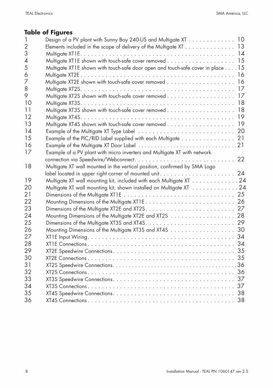
Table of Figures1 Design of a PV plant with Sunny Boy 240-US and Multigate XT . . . . . . . . . . . . . 102 Elements included in the scope of delivery of the Multigate XT . . . . . . . . . . . . . . 133 Multigate XT1E. . . . . . . . . . . . . . . . . . . . . . . . . . . . . . . . . . . . . . . . . . . 144 Multigate XT1E shown with touch-safe cover removed . . . . . . . . . . . . . . . . . . . 155 Multigate XT1E shown with touch-safe door open and touch-safe cover in place . . . . 156 Multigate XT2E . . . . . . . . . . . . . . . . . . . . . . . . . . . . . . . . . . . . . . . . . . . 167 Multigate XT2E shown with touch-safe cover removed . . . . . . . . . . . . . . . . . . . 168 Multigate XT2S. . . . . . . . . . . . . . . . . . . . . . . . . . . . . . . . . . . . . . . . . . . 179 Multigate XT2S shown with touch-safe cover removed . . . . . . . . . . . . . . . . . . . 1710 Multigate XT3S. . . . . . . . . . . . . . . . . . . . . . . . . . . . . . . . . . . . . . . . . . . 1811 Multigate XT3S shown with touch-safe cover removed . . . . . . . . . . . . . . . . . . . 1812 Multigate XT4S. . . . . . . . . . . . . . . . . . . . . . . . . . . . . . . . . . . . . . . . . . . 1913 Multigate XT4S shown with touch-safe cover removed . . . . . . . . . . . . . . . . . . . 1914 Example of the Multigate XT Type Label . . . . . . . . . . . . . . . . . . . . . . . . . . . 2015 Example of the PIC/RID Label supplied with each Multigate . . . . . . . . . . . . . . . 2116 Example of the Multigate XT Door Label . . . . . . . . . . . . . . . . . . . . . . . . . . . . . . . 2117 Example of a PV plant with micro inverters and Multigate XT with network connection via Speedwire/Webconnect. . . . . . . . . . . . . . . . . . . . . . . . . . . . 2218 Multigate XT wall mounted in the vertical position, confirmed by SMA Logo label located in upper right corner of mounted unit . . . . . . . . . . . . . . . . . . . . . 2419 Multigate XT wall mounting kit, included with each Multigate XT . . . . . . . . . . . . . 2420 Multigate XT wall mounting kit, shown installed on Multigate XT . . . . . . . . . . . . . 2421 Dimensions of the Multigate XT1E . . . . . . . . . . . . . . . . . . . . . . . . . . . . . . . 2522 Mounting Dimensions of the Multigate XT1E . . . . . . . . . . . . . . . . . . . . . . . . . 2623 Dimensions of the Multigate XT2E and XT2S. . . . . . . . . . . . . . . . . . . . . . . . . 2724 Mounting Dimensions of the Multigate XT2E and XT2S . . . . . . . . . . . . . . . . . . 2825 Dimensions of the Multigate XT3S and XT4S. . . . . . . . . . . . . . . . . . . . . . . . . 2926 Mounting Dimensions of the Multigate XT3S and XT4S . . . . . . . . . . . . . . . . . . 3027 XT1E Input Wiring. . . . . . . . . . . . . . . . . . . . . . . . . . . . . . . . . . . . . . . . . 3428 XT1E Connections . . . . . . . . . . . . . . . . . . . . . . . . . . . . . . . . . . . . . . . . . 3429 XT2E Speedwire Connections. . . . . . . . . . . . . . . . . . . . . . . . . . . . . . . . . . 3530 XT2E Connections . . . . . . . . . . . . . . . . . . . . . . . . . . . . . . . . . . . . . . . . . 3531 XT2S Speedwire Connections. . . . . . . . . . . . . . . . . . . . . . . . . . . . . . . . . . . . . . . 3632 XT2S Connections . . . . . . . . . . . . . . . . . . . . . . . . . . . . . . . . . . . . . . . . . 3633 XT3S Speedwire Connections. . . . . . . . . . . . . . . . . . . . . . . . . . . . . . . . . . 3734 XT3S Connections . . . . . . . . . . . . . . . . . . . . . . . . . . . . . . . . . . . . . . . . . 3735 XT4S Speedwire Connections. . . . . . . . . . . . . . . . . . . . . . . . . . . . . . . . . . 3836 XT4S Connections . . . . . . . . . . . . . . . . . . . . . . . . . . . . . . . . . . . . . . . . . 38
Installation Manual - TEAL PN 1060147 rev 2.5 9
TEAL Electronics SMA America, LLC
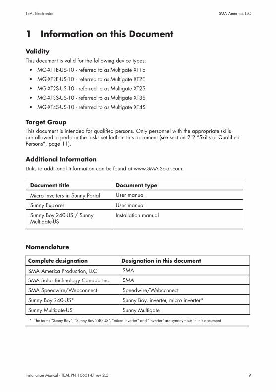
1 Information on this Document
ValidityThis document is valid for the following device types:
• MG-XT1E-US-10 - referred to as Multigate XT1E
• MG-XT2E-US-10 - referred to as Multigate XT2E
• MG-XT2S-US-10 - referred to as Multigate XT2S
• MG-XT3S-US-10 - referred to as Multigate XT3S
• MG-XT4S-US-10 - referred to as Multigate XT4S
Target GroupThis document is intended for qualified persons. Only personnel with the appropriate skills are allowed to perform the tasks set forth in this document (see section 2.2 “Skills of Qualified Persons”, page 11).
Additional InformationLinks to additional information can be found at www.SMA-Solar.com:
Document title Document type
Micro Inverters in Sunny Portal User manual
Sunny Explorer User manual
Sunny Boy 240-US / Sunny Multigate-US
Installation manual
Nomenclature
Complete designation Designation in this document
SMA America Production, LLC SMA
SMA Solar Technology Canada Inc. SMA
SMA Speedwire/Webconnect Speedwire/Webconnect
Sunny Boy 240-US* Sunny Boy, inverter, micro inverter*
Sunny Multigate-US Sunny Multigate
* The terms “Sunny Boy”, “Sunny Boy 240-US”, “micro inverter” and “inverter” are synonymous in this document.
Installation Manual - TEAL PN 1060147 rev 2.510
TEAL Electronics SMA America, LLC
2 Safety
2.1 Intended Use
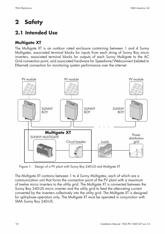
Multigate XTThe Multigate XT is an outdoor rated enclosure containing between 1 and 4 Sunny Multigates, associated terminal blocks for inputs from each string of Sunny Boy micro inverters, associated terminal blocks for outputs of each Sunny Multigate to the AC Grid connection point, and associated hardware for Speedwire/Webconnect (related to Ethernet) connection for monitoring system performance over the internet.
Figure 1: Design of a PV plant with Sunny Boy 240-US and Multigate XT
The Multigate XT contains between 1 to 4 Sunny Multigates, each of which are a communication unit that forms the connection point of the PV plant with a maximum of twelve micro inverters to the utility grid. The Multigate XT is connected between the Sunny Boy 240-US micro inverter and the utility grid to feed the alternating current converted by the inverters collectively into the utility grid. The Multigate XT is designed for split-phase operation only. The Multigate XT must be operated in conjunction with SMA Sunny Boy 240-US.
Multigate XT

Installation Manual - TEAL PN 1060147 rev 2.5 11
TEAL Electronics SMA America, LLC
The Multigate XT is designed in a dust-tight and water-tight industrial enclosure complying with the fire protection class 5VA and pollution degree 3. The enclosure must comply at a minimum with UL50 Type 3 when conduits are installed.
For safety reasons, it is forbidden to modify the product or install components that are not explicitly recommended for this product.
Only use the Multigate XT in accordance with the information provided in the enclosed documentation. Any other use can result in personal injury or property damage.
• Each Multigate XT contains from 1 to 4 Sunny Multigates. The model number designation contains the number of Sunny Multigates in each Multigate XT. Model XT1 contains 1 Sunny Mulitgate. Model XT2 contains 2 Sunny Multigates. Model XT3 contains 3 Sunny Multigates. Model XT4 contains 4 Sunny Multigates.
• A maximum of twelve micro inverters can be connected to each Sunny Multigate.• No loads may be connected between the Sunny Multigate and the circuit breaker.• The grounding conductor of the AC cable from the inverter must be connected to the corresponding Sunny Multigate grounding terminal in the Multigate XT.• The output grounding conductor of the Multigate XT must be connected to the
equipotential bonding of the AC distribution board.• The Sunny Multigate must not be opened.
The enclosed documentation is an integral part of this product.• Read and observe the documentation.• Keep the documentation in a convenient place for future reference.
2.2 Skills of Qualified PersonsThe tasks described in this document must be performed by qualified persons only. Qualified persons must have the following skills:
• Knowledge of how an inverter works and is operated• Training in how to deal with the dangers and risks associated with installing and
using electrical devices and plants• Training in the installation and commissioning of electrical devices and plants• Knowledge of the applicable standards and guidelines• Knowledge of and observance of this document and all safety precautions
Installation Manual - TEAL PN 1060147 rev 2.512
TEAL Electronics SMA America, LLC
2.3 Safety Precautions
Str
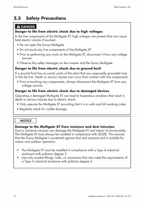
Danger to life from electric shock due to high voltagesIn the live components of the Multigate XT, high voltages are present that can cause fatal electric shocks if touched.• Do not open the Sunny Multigate.• Do not touch any live components of the Multigate XT.• Prior to performing any work on the Multigate XT, disconnect it from any voltage
sources.• Observe the safety messages on the inverter and the Sunny Multigate.
Danger to life from electric shock due to ground faultIf a ground fault has occurred, parts of the plant that are supposedly grounded may in fact be live. Death or serious injuries can occur from contact with live components.• Prior to touching any components, always disconnect the Multigate XT from any
voltage sources.
Danger to life from electric shock due to damaged devicesOperating a damaged Multigate XT can lead to hazardous situations that result in death or serious injuries due to electric shock.• Only operate the Multigate XT providing that it is in safe and full working order.• Regularly check for visible damage.
Damage to the Multigate XT from moisture and dust intrusionDust or moisture intrusion can damage the Multigate XT and impair its functionality. The Multigate XT must always be installed in compliance with UL50E. This ensures that the Sunny Multigate is protected against dust and moisture and is suitable for indoor and outdoor operation.
• The Multigate XT must be installed in compliance with a Type 4 industrial enclosure with pollution degree 3.
• Use only conduit fittings, hubs, or connectors that also meet the requirements of a Type 4 industrial enclosure with pollution degree 3.
Installation Manual - TEAL PN 1060147 rev 2.5 13
TEAL Electronics SMA America, LLC
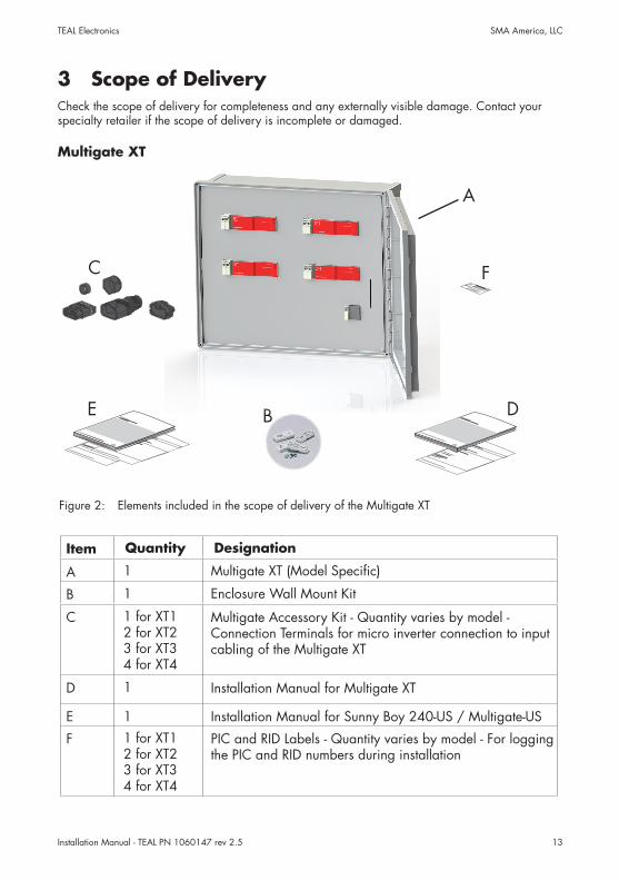
3 Scope of DeliveryCheck the scope of delivery for completeness and any externally visible damage. Contact your specialty retailer if the scope of delivery is incomplete or damaged.
Multigate XT
Figure 2: Elements included in the scope of delivery of the Multigate XT
Item Quantity Designation
A 1 Multigate XT (Model Specific)
B 1 Enclosure Wall Mount Kit
C 1 for XT12 for XT23 for XT34 for XT4
Multigate Accessory Kit - Quantity varies by model - Connection Terminals for micro inverter connection to input cabling of the Multigate XT
D 1 Installation Manual for Multigate XT
E 1 Installation Manual for Sunny Boy 240-US / Multigate-US
F 1 for XT12 for XT23 for XT34 for XT4
PIC and RID Labels - Quantity varies by model - For logging the PIC and RID numbers during installation
B
A
D
C
E
F

Installation Manual - TEAL PN 1060147 rev 2.514
TEAL Electronics SMA America, LLC
4 Product Description
4.1 Multigate XTThe Multigate XT is an outdoor rated enclosure containing between 1 and 4 Sunny Multigates, associated terminal blocks for inputs from each string of Sunny Boy micro inverters, associated terminal blocks for outputs of each Sunny Multigate to the AC Grid connection point, and associated hardware for Speedwire (related to Ethernet) connection for monitoring system performance over the internet.
Each Sunny Multigate installed in the Multigate XT is a communication unit that forms the connection point of the PV plant with a maximum of twelve micro inverters to the utility grid. The Multigate XT is connected between the micro inverter and the utility grid to feed the alternating current converted by the inverters collectively into the utility grid. The Multigate XT is designed for split-phase operation only. The Multigate XT must be operated in conjunction with SMA Sunny Boy 240-US.
4.2 Multigate XT Models
Figure 3: Multigate XT1E.
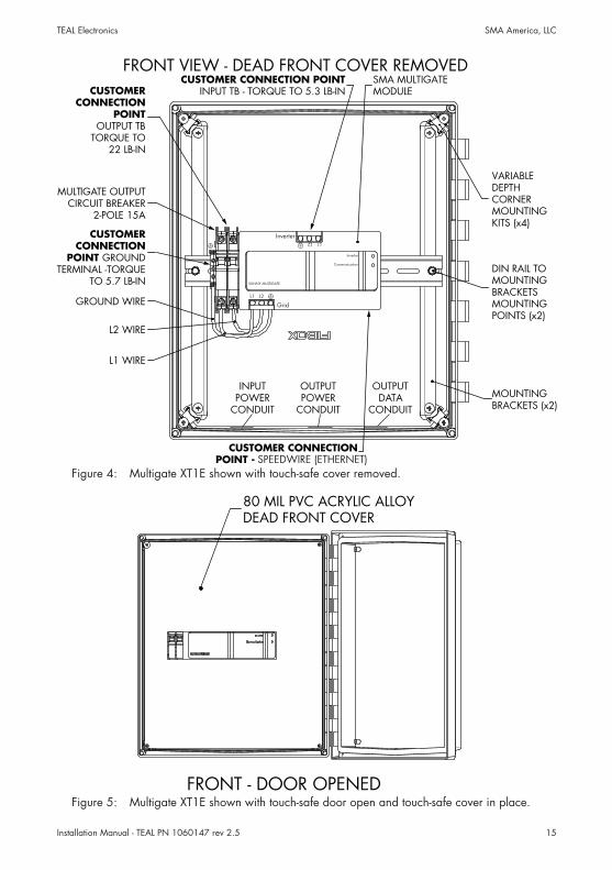
Model XT1E:For systems with up to 12 Sunny Boy 240-US micro inverters, handling up to 2880W of AC power at 240VAC.Contains 1 Sunny Multigate with a 2-pole 15A output circuit breaker.Input connections are direct to the input terminals of the Sunny Multigate.Output connections are to the output circuit breaker and associated ground terminal.RJ-45 Ethernet connection is directly on the Sunny Multigate to connect the SMA Speedwire/Webconnect system.
Multigate XT1E Shownwith Door Open and
Touch Safe Cover in place
Installation Manual - TEAL PN 1060147 rev 2.5 15
TEAL Electronics SMA America, LLC
Figure 4: Multigate XT1E shown with touch-safe cover removed.
FRONT - DOOR OPENED
80 MIL PVC ACRYLIC ALLOYDEAD FRONT COVER
Figure 5: Multigate XT1E shown with touch-safe door open and touch-safe cover in place.
CUSTOMERCONNECTION
POINT GROUNDTERMINAL -TORQUE
TO 5.7 LB-IN
VARIABLEDEPTHCORNERMOUNTINGKITS (x4)
CUSTOMER CONNECTION POINTINPUT TB - TORQUE TO 5.3 LB-IN
SMA MULTIGATEMODULE
GROUND WIRE
L1 WIRE
L2 WIRE
MOUNTINGBRACKETS (x2)
MULTIGATE OUTPUTCIRCUIT BREAKER
2-POLE 15A
CUSTOMERCONNECTION
POINTOUTPUT TB
TORQUE TO22 LB-IN
CUSTOMER CONNECTIONPOINT - SPEEDNET (ETHERNET)
DIN RAIL TOMOUNTINGBRACKETSMOUNTINGPOINTS (x2)
Inverter
SUNNY MULTIGATE
Communication
Inverter
GridL1 L2
L1 L2
INPUTPOWER
CONDUIT
OUTPUTPOWER
CONDUIT
OUTPUTDATA
CONDUIT
FRONT VIEW - DEAD FRONT COVER REMOVED
SPEEDWIRE (ETHERNET)
Installation Manual - TEAL PN 1060147 rev 2.516
TEAL Electronics SMA America, LLC
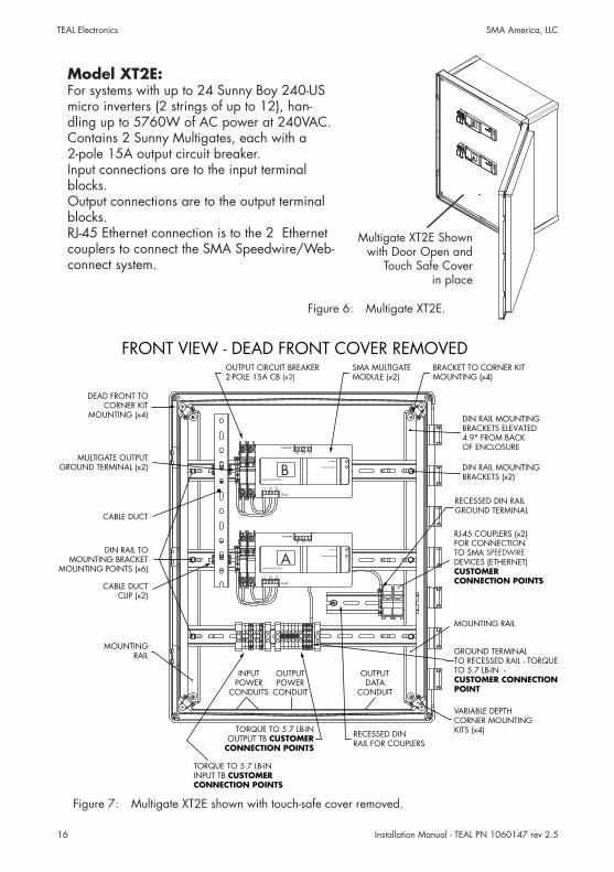
Figure 6: Multigate XT2E.
Figure 7: Multigate XT2E shown with touch-safe cover removed.
Model XT2E:For systems with up to 24 Sunny Boy 240-US micro inverters (2 strings of up to 12), han-dling up to 5760W of AC power at 240VAC.Contains 2 Sunny Multigates, each with a 2-pole 15A output circuit breaker.Input connections are to the input terminal blocks.Output connections are to the output terminal blocks.RJ-45 Ethernet connection is to the 2 Ethernet couplers to connect the SMA Speedwire/Web-connect system.
Multigate XT2E Shownwith Door Open and
Touch Safe Cover in place
BRACKET TO CORNER KITMOUNTING (x4)
OUTPUT CIRCUIT BREAKER2-POLE 15A CB (x4)
SMA MULTIGATEMODULE (x2)
MOUNTING RAIL
RECESSED DINRAIL FOR COUPLERS
TORQUE TO 5.7 LB-INOUTPUT TB CUSTOMER
CONNECTION POINTS
RJ-45 COUPLERS (x2)FOR CONNECTIONTO SMA SPEEDNETDEVICES (ETHERNET)CUSTOMERCONNECTION POINTS
DIN RAIL TOMOUNTING BRACKET
MOUNTING POINTS (x6)
DEAD FRONT TOCORNER KIT
MOUNTING (x4)
MOUNTINGRAIL
MULTIGATE OUTPUTGROUND TERMINAL (x2)
VARIABLE DEPTHCORNER MOUNTINGKITS (x4)
TORQUE TO 5.7 LB-ININPUT TB CUSTOMERCONNECTION POINTS
Inverter
Inverter
Communication
SUNNY MULTIGATE
Grid
L1 L2 G
L1 L2 G
Inverter
Inverter
Communication
SUNNY MULTIGATE
Grid
L1 L2 G
L1 L2 G
A
B
INPUTPOWER
CONDUITS
OUTPUTPOWER
CONDUIT
OUTPUTDATA
CONDUIT
CABLE DUCTCLIP (x2)
CABLE DUCT
DIN RAIL MOUNTINGBRACKETS (x2)
DIN RAIL MOUNTINGBRACKETS ELEVATED4.9" FROM BACKOF ENCLOSURE
RECESSED DIN RAILGROUND TERMINAL
GROUND TERMINALTO RECESSED RAIL - TORQUETO 5.7 LB-IN -CUSTOMER CONNECTIONPOINT
FRONT VIEW - DEAD FRONT COVER REMOVED
SPEEDWIRE
(x2)
Installation Manual - TEAL PN 1060147 rev 2.5 17
TEAL Electronics SMA America, LLC
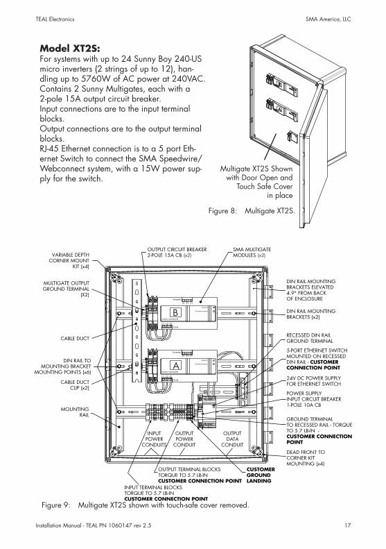
Figure 9: Multigate XT2S shown with touch-safe cover removed.
Figure 8: Multigate XT2S.
CUSTOMER CONNECTION POINT
SMA MULTIGATEMODULES (x4)
OUTPUT CIRCUIT BREAKER2-POLE 15A CB (x4)
CABLE DUCTCLIP (x2)
MULTIGATE OUTPUTGROUND TERMINAL
(X2)
VARIABLE DEPTHCORNER MOUNT
KIT (x4)
CABLE DUCT
INPUT TERMINAL BLOCKSTORQUE TO 5.7 LB-IN
OUTPUT TERMINAL BLOCKSTORQUE TO 5.7 LB-INCUSTOMER CONNECTION POINT
CUSTOMERGROUNDLANDING
5-PORT ETHERNET SWITCHMOUNTED ON RECESSEDDIN RAIL - CUSTOMERCONNECTION POINT
24V DC POWER SUPPLYFOR ETHERNET SWITCH
DIN RAIL MOUNTINGBRACKETS (x2)
POWER SUPPLYINPUT CIRCUIT BREAKER1-POLE 10A CB
RECESSED DIN RAILGROUND TERMINAL
DIN RAIL MOUNTINGBRACKETS ELEVATED4.9" FROM BACKOF ENCLOSURE
GROUND TERMINALTO RECESSED RAIL - TORQUETO 5.7 LB-IN -CUSTOMER CONNECTIONPOINT
Inverter
Inverter
Communication
SUNNY MULTIGATE
GridL1 L2 G
L1 L2 G
Inverter
Inverter
Communication
SUNNY MULTIGATE
GridL1 L2 G
L1 L2 G
A
B
INPUTPOWER
CONDUITS
OUTPUTPOWER
CONDUIT
OUTPUTDATA
CONDUIT
DIN RAIL TOMOUNTING BRACKET
MOUNTING POINTS (x6)
DEAD FRONT TOCORNER KITMOUNTING (x4)
MOUNTINGRAIL
Model XT2S:For systems with up to 24 Sunny Boy 240-US micro inverters (2 strings of up to 12), han-dling up to 5760W of AC power at 240VAC.Contains 2 Sunny Multigates, each with a 2-pole 15A output circuit breaker.Input connections are to the input terminal blocks.Output connections are to the output terminal blocks.RJ-45 Ethernet connection is to a 5 port Eth-ernet Switch to connect the SMA Speedwire/Webconnect system, with a 15W power sup-ply for the switch.
Multigate XT2S Shownwith Door Open and
Touch Safe Cover in place
(x2)(x2)
Installation Manual - TEAL PN 1060147 rev 2.518
TEAL Electronics SMA America, LLC
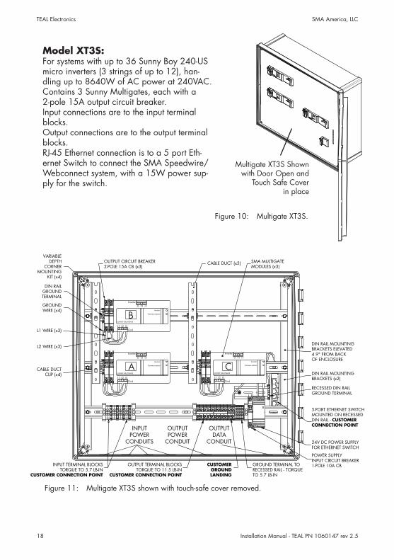
Figure 11: Multigate XT3S shown with touch-safe cover removed.
Figure 10: Multigate XT3S.
Model XT3S:For systems with up to 36 Sunny Boy 240-US micro inverters (3 strings of up to 12), han-dling up to 8640W of AC power at 240VAC.Contains 3 Sunny Multigates, each with a 2-pole 15A output circuit breaker.Input connections are to the input terminal blocks.Output connections are to the output terminal blocks.RJ-45 Ethernet connection is to a 5 port Eth-ernet Switch to connect the SMA Speedwire/Webconnect system, with a 15W power sup-ply for the switch.
Multigate XT3S Shownwith Door Open and
Touch Safe Cover in place
CABLE DUCTCLIP (x4)
DIN RAILGROUNDTERMINAL
GROUND TERMINAL TORECESSED RAIL - TORQUETO 5.7 LB-IN
5-PORT ETHERNET SWITCHMOUNTED ON RECESSEDDIN RAIL - CUSTOMERCONNECTION POINT
24V DC POWER SUPPLYFOR ETHERNET SWITCH
DIN RAIL MOUNTINGBRACKETS (x2)
POWER SUPPLYINPUT CIRCUIT BREAKER1-POLE 10A CB
SMA MULTIGATEMODULES (x3)
RECESSED DIN RAILGROUND TERMINAL
DIN RAIL MOUNTINGBRACKETS ELEVATED4.9" FROM BACKOF ENCLOSURE
GROUNDWIRE (x4)
INPUT TERMINAL BLOCKSTORQUE TO 5.7 LB-IN
CUSTOMER CONNECTION POINT
OUTPUT TERMINAL BLOCKSTORQUE TO 11.5 LB-IN
CUSTOMER CONNECTION POINT
L1 WIRE (x3)
L2 WIRE (x3)
VARIABLEDEPTH
CORNERMOUNTING
KIT (x4)
CUSTOMERGROUNDLANDING
OUTPUT CIRCUIT BREAKER2-POLE 15A CB (x3)
CABLE DUCT (x2)
Inverter
Inverter
Communication
SUNNY MULTIGATE
GridL1 L2 G
L1 L2 G
B
Inverter
Inverter
Communication
SUNNY MULTIGATE
GridL1 L2 G
L1 L2 G
A
Inverter
Inverter
Communication
SUNNY MULTIGATE
GridL1 L2 G
L1 L2 G
C
INPUTPOWER
CONDUITS
OUTPUTPOWER
CONDUIT
OUTPUTDATA
CONDUIT
Installation Manual - TEAL PN 1060147 rev 2.5 19
TEAL Electronics SMA America, LLC
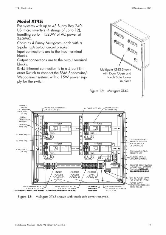
Figure 13: Multigate XT4S shown with touch-safe cover removed.
Figure 12: Multigate XT4S.
Model XT4S:For systems with up to 48 Sunny Boy 240-US micro inverters (4 strings of up to 12), handling up to 11520W of AC power at 240VAC.Contains 4 Sunny Multigates, each with a 2-pole 15A output circuit breaker.Input connections are to the input terminal blocks.Output connections are to the output terminal blocks.RJ-45 Ethernet connection is to a 5 port Eth-ernet Switch to connect the SMA Speedwire/Webconnect system, with a 15W power sup-ply for the switch.
Multigate XT4S Shownwith Door Open and
Touch Safe Cover in place
CABLE DUCTCLIP (x4)
DIN RAILGROUNDTERMINAL
GROUND TERMINAL TORECESSED RAIL - TORQUETO 5.7 LB-IN
5-PORT ETHERNET SWITCHMOUNTED ON RECESSEDDIN RAIL - CUSTOMERCONNECTION POINT
24V DC POWER SUPPLYFOR ETHERNET SWITCH
DIN RAIL MOUNTINGBRACKETS (x2)
POWER SUPPLYINPUT CIRCUIT BREAKER1-POLE 10A CB
SMA MULTIGATEMODULES (x4)
RECESSED DIN RAILGROUND TERMINAL
DIN RAIL MOUNTINGBRACKETS ELEVATED4.9" FROM BACKOF ENCLOSURE
GROUNDWIRE (x4)
INPUT TERMINAL BLOCKSTORQUE TO 5.7 LB-IN
CUSTOMER CONNECTION POINT
OUTPUT TERMINAL BLOCKSTORQUE TO 11.5 LB-IN
CUSTOMER CONNECTION POINT
L1 WIRE (x4)
L2 WIRE (x4)
VARIABLEDEPTH
CORNERMOUNTING
KIT (x4)
CUSTOMERGROUNDLANDING
OUTPUT CIRCUIT BREAKER2-POLE 15A CB (x4)
CABLE DUCT (x2)
Inverter
Inverter
Communication
SUNNY MULTIGATE
GridL1 L2 G
L1 L2 G
B
Inverter
Inverter
Communication
SUNNY MULTIGATE
GridL1 L2 G
L1 L2 G
A
Inverter
Inverter
Communication
SUNNY MULTIGATE
GridL1 L2 G
L1 L2 G
C
Inverter
Inverter
Communication
SUNNY MULTIGATE
GridL1 L2 G
L1 L2 G
D
INPUTPOWER
CONDUITS
OUTPUTPOWER
CONDUIT
OUTPUTDATA
CONDUIT
Installation Manual - TEAL PN 1060147 rev 2.520
TEAL Electronics SMA America, LLC
4.3 Type Labels and Stickers
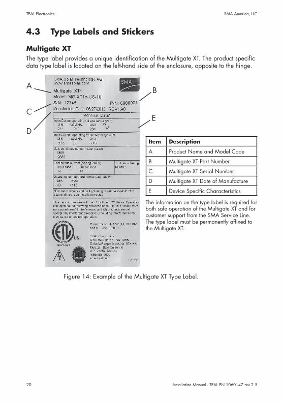
Multigate XTThe type label provides a unique identification of the Multigate XT. The product specific data type label is located on the left- hand side of the enclosure, opposite to the hinge.
The information on the type label is required for both safe operation of the Multigate XT and for customer support from the SMA Service Line. The type label must be permanently affixed to the Multigate XT.
Item Description
A Product Name and Model Code
B Multigate XT Part Number
C Multigate XT Serial Number
D Multigate XT Date of Manufacture
E Device Specific Characteristics
Figure 14: Example of the Multigate XT Type Label.
A
C
B
E
D
Installation Manual - TEAL PN 1060147 rev 2.5 21
TEAL Electronics SMA America, LLC
PIC
/ R
IDLa
bel f
or
Mul
tigat
e A
PIC
/ R
IDLa
bel f
or
Mul
tigat
e B
PIC
/ R
IDLa
bel f
or
Mul
tigat
e C
Des
igne
d an
d M
anuf
actu
red
excl
usiv
ely
for S
MA
by
TEA
L El
ectro
nics
ww
w.te
al.c
om -
103
50 S
orre
nto
Valle
y Ro
ad, S
an D
iego
, CA
921
21 -
858
-558
-900
0
Insta
llatio
n G
uide
for S
MA
Mul
tigat
e XT
- M
odel
XT3
s - T
EAL
PN 6
9000
07FR
ON
T VI
EW -
DEA
D F
RON
T C
OVE
R RE
MO
VED
CA
BLE
DU
CT
CLIP
(x4)
DIN
RA
ILG
ROU
ND
TERM
INA
L
GRO
UN
D T
ERM
INA
L TO
REC
ESSE
D R
AIL
- TO
RQU
ETO
5.7
LB-
IN -
CU
STO
MER
CO
NN
ECTI
ON
PO
INTS
5-PO
RT E
THER
NET
SW
ITC
HM
OU
NTE
D O
N R
ECES
SED
DIN
RA
IL - C
UST
OM
ERCO
NN
ECTI
ON
PO
INTS
24V
DC
PO
WER
SU
PPLY
FOR
ETH
ERN
ET S
WIT
CH
DIN
RA
IL M
OU
NTI
NG
BRA
CKE
TS (x
2)
POW
ER S
UPP
LYIN
PUT
CIR
CU
IT B
REA
KER
1-PO
LE 1
0A C
B
SMA
MU
LTIG
ATE
MO
DU
LES
(x3)
REC
ESSE
D D
IN R
AIL
GRO
UN
D T
ERM
INA
L
DIN
RA
IL M
OU
NTI
NG
BRA
CKE
TS E
LEVA
TED
4.9"
FRO
M B
AC
KO
F EN
CLO
SURE
GRO
UN
DW
IRE
(x4)
INPU
T TE
RMIN
AL
BLO
CKS
TORQ
UE
TO 5
.7 L
B-IN
CU
STO
MER
CO
NN
ECTI
ON
PO
INTS
OU
TPU
T TE
RMIN
AL
BLO
CKS
TORQ
UE
TO 1
1.5
LB-IN
CU
STO
MER
CO
NN
ECTI
ON
PO
INTS
L1 W
IRE
(x3)
L2 W
IRE
(x3)
VARI
ABL
ED
EPTH
CO
RNER
MO
UN
TIN
GKI
T (x
4)
CU
STO
MER
GRO
UN
DLA
ND
ING
OU
TPU
T C
IRC
UIT
BRE
AKE
R2-
POLE
15A
CB
(x3)
CA
BLE
DU
CT
(x2)
Inve
rter
Inve
rter
Com
mun
icat
ion
SUN
NY
MU
LTIG
ATE
Grid
L1 L
2
L1 L2
B Inve
rter
Inve
rter
Com
mun
icat
ion
SUN
NY
MU
LTIG
ATE
Grid
L1 L
2
L1 L2
A
Inve
rter
Inve
rter
Com
mun
icat
ion
SUN
NY
MU
LTIG
ATE
Grid
L1 L
2
L1 L2
C
INPU
TSFi
eld
Con
nect
ions
L1|L
2| AL1
|L2| B
L1|L
2| C
INPU
TSA
L1|L
2|C
L1|L
2|L1
A |
B |
C |
|
PSL2
A |
B |
C | D
NPS
A|B
|C|D
L1N
OU
TPU
TS
OU
TPU
TSB
L1|L
2|
Fact
ory
Con
nect
ions
- To
/Fro
mM
ultig
ate
Mod
ules
(TO
WA
RDM
ULT
IGA
TES)
L2
Warn
ing:
- All
elec
trica
l ins
talla
tions
mus
t be
done
in a
ccor
danc
e w
ith th
e lo
cal
and
Nat
iona
l Ele
ctric
al C
ode®
or A
NSI
/NFP
A 7
0. T
his
docu
men
t do
es n
ot re
plac
e an
y lo
cal,
state
, pro
vinc
ial,
fede
ral o
r nat
iona
l la
ws,
regu
latio
n or
cod
es a
pplic
able
to th
e in
stalla
tion
and
use
of
the
prod
uct.
All
insta
llatio
ns m
ust c
onfo
rm w
ith th
e la
ws,
regu
latio
ns,
code
s an
d sta
ndar
ds a
pplic
able
in th
e ju
risdi
ctio
n of
insta
llatio
n.
- Bef
ore
conn
ectin
g th
e pr
oduc
t to
the
elec
trica
l util
ity g
rid, c
onta
ct th
e lo
cal u
tility
com
pany
. Thi
s co
nnec
tion
mus
t be
mad
e by
qua
li�ed
pe
rson
nel o
nly.
- Wiri
ng o
f the
pro
duct
mus
t be
mad
e by
qua
li�ed
per
sonn
el o
nly.
- See
dia
gram
for C
usto
mer
Con
nect
ion
Poin
ts an
d to
rque
sp
eci�
catio
ns o
f eac
h cu
stom
er c
onne
ctio
n po
int.
- See
dia
gram
for l
ayou
t of m
ajor
com
pone
nts.
- Use
75C
rate
d C
oppe
r con
duct
ors
only,
do
not u
se �
ne s
trand
ed
wire
s.- U
se o
nly
the
prov
ided
con
duit
hole
s or
kno
ck-o
uts
to a
ttach
con
duits
w
ith N
EMA
4 �
tting
s on
ly.- S
eal u
nuse
d ho
les
with
NEM
A 4
�tti
ngs
only.
- For
com
mis
sion
ing
and
oper
atin
g in
struc
tions
, ref
er to
use
r man
ual.
- Ref
er to
Mul
tigat
e M
anua
l for
LED
s m
eani
ngs.
- Atta
ch s
afet
y co
ver h
ardw
are
to �
nger
-tigh
t onl
y.
Spec
i�ca
tion T
able
: M
odel
V
olta
ge R
atin
g C
urre
nt R
atin
gXT
3s
2
40VA
C
36
A
Inpu
t Wire
Siz
e
Out
put W
ire S
ize
#22
to #
10AW
G
#2
0 to
#6A
WG
INPU
TPO
WER
CO
ND
UIT
S
OU
TPU
TPO
WER
CO
ND
UIT
OU
TPU
TD
ATA
CO
ND
UIT
∩ ∪
TEA
L PN
061
0770
, rev
1.2
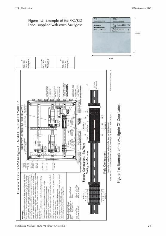
Figu
re 1
6: E
xam
ple
of th
e M
ultig
ate
XT D
oor L
abel
.
Figure 15: Example of the PIC/RID Label supplied with each Multigate.

Installation Manual - TEAL PN 1060147 rev 2.522
TEAL Electronics SMA America, LLC
4.4 Communication
Communication between inverter and Sunny MultigateThe inverters are connected to the Multigate XT, and consequently the Sunny Multigate, via the AC cable. The communication and data transmission between the Sunny Multigate and the inverters takes place via a Powerline interface.
Communication between Sunny Multigate and other communication products Communication between the Sunny Multigate and other SMA communication products (e.g. Sunny Portal, Sunny Explorer) takes place via Speedwire. Speedwire is an Ethernet-based type of communication. You can connect the Sunny Multigate to your network via Speedwire. The Webconnect function enables data exchange between Sunny Multigate and Sunny Portal. Sunny Portal is an Internet portal for the monitoring of plants as well as for the visualization and presentation of plant data. In order to establish a connection to Sunny Portal, the Sunny Multigate must be connected to a router with Internet connection and be integrated into your network. To enable data exchange between Sunny Multigate and Sunny Portal, you must register the PV plant in Sunny Portal (see user manual of Webconnect plants in Sunny Portal at www.SMA-Solar.com). For this purpose, you will need the access data, identification key (PIC) and registration ID (RID) which are located on the type label of the Sunny Multigate and the inside of the door of the Multigate XT. Once you have registered the Sunny Multigate, you will be able to monitor your PV plant in Sunny Portal.
Figure 17: Example of a PV plant with micro inverters and Multigate XT with network connection via Speedwire/Webconnect.
Multigate XT
Installation Manual - TEAL PN 1060147 rev 2.5 23
TEAL Electronics SMA America, LLC
5 Mounting
5.1 Selecting the Multigate XT Mounting LocationRequirements for the mounting location:
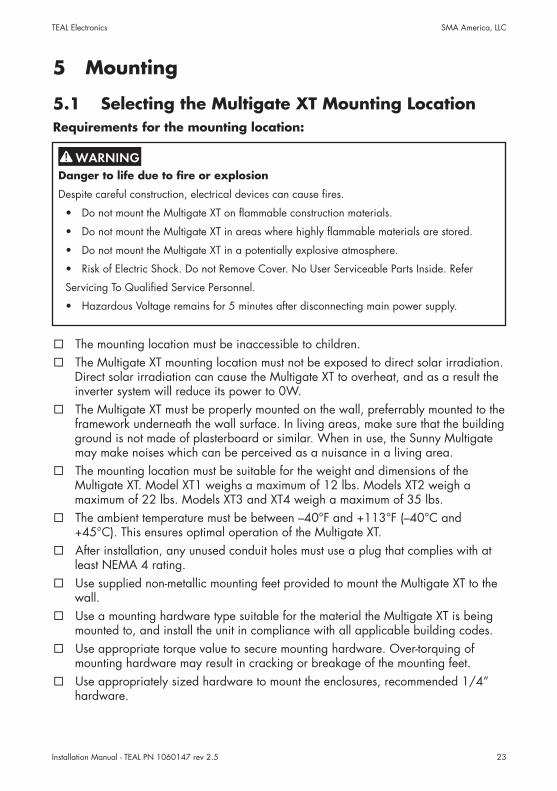
The mounting location must be inaccessible to children. The Multigate XT mounting location must not be exposed to direct solar irradiation.
Direct solar irradiation can cause the Multigate XT to overheat, and as a result the inverter system will reduce its power to 0W.
The Multigate XT must be properly mounted on the wall, preferrably mounted to the framework underneath the wall surface. In living areas, make sure that the building ground is not made of plasterboard or similar. When in use, the Sunny Multigate may make noises which can be perceived as a nuisance in a living area.
The mounting location must be suitable for the weight and dimensions of the Multigate XT. Model XT1 weighs a maximum of 12 lbs. Models XT2 weigh a maximum of 22 lbs. Models XT3 and XT4 weigh a maximum of 35 lbs.
The ambient temperature must be between –40°F and +113°F (–40°C and +45°C). This ensures optimal operation of the Multigate XT.
After installation, any unused conduit holes must use a plug that complies with at least NEMA 4 rating.
Use supplied non-metallic mounting feet provided to mount the Multigate XT to the wall.
Use a mounting hardware type suitable for the material the Multigate XT is being mounted to, and install the unit in compliance with all applicable building codes.
Use appropriate torque value to secure mounting hardware. Over-torquing of mounting hardware may result in cracking or breakage of the mounting feet.
Use appropriately sized hardware to mount the enclosures, recommended 1/4” hardware.
Danger to life due to fire or explosion
Despite careful construction, electrical devices can cause fires.
• Do not mount the Multigate XT on flammable construction materials.
• Do not mount the Multigate XT in areas where highly flammable materials are stored.
• Do not mount the Multigate XT in a potentially explosive atmosphere.
• Risk of Electric Shock. Do not Remove Cover. No User Serviceable Parts Inside. Refer
Servicing To Qualified Service Personnel.
• Hazardous Voltage remains for 5 minutes after disconnecting main power supply.
Installation Manual - TEAL PN 1060147 rev 2.524
TEAL Electronics SMA America, LLC
5.2 Mounting the Multigate XT
a. Tools required - Philips head screwdriver to attach mounting feet to enclosure. Other tools as needed to attach mounting feet and enclosure to wall (this can vary by installation depending on the wall material, thickness, etc.).
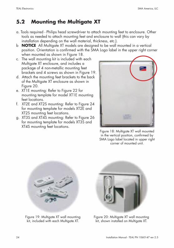
b NOTICE All Multigate XT models are designed to be wall mounted in a vertical position. Orientation is confirmed with the SMA Logo label in the upper right corner when mounted as shown in Figure 18.
c. The wall mounting kit is included with each Multigate XT enclosure, and includes a package of 4 non-metallic mounting feet brackets and 4 screws as shown in Figure 19.
d. Attach the mounting feet brackets to the back of the Multigate XT enclosure as shown in Figure 20.
e. XT1E mounting: Refer to Figure 22 for mounting template for model XT1E mounting feet locations.
f. XT2E and XT2S mounting: Refer to Figure 24 for mounting template for models XT2E and XT2S mounting feet locations.
g. XT3S and XT4S mounting: Refer to Figure 26 for mounting template for models XT3S and XT4S mounting feet locations.
Figure 19: Multigate XT wall mounting kit, included with each Multigate XT.
Figure 20: Multigate XT wall mounting kit, shown installed on Multigate XT.
Figure 18: Multigate XT wall mounted in the vertical position, confirmed by
SMA Logo label located in upper right corner of mounted unit.
Installation Manual - TEAL PN 1060147 rev 2.5 25
TEAL Electronics SMA America, LLC
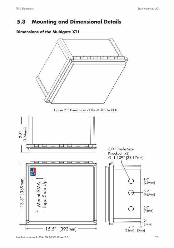
Dimensions of the Multigate XT1
7.6”
[194
mm
]13
.3”
[339
mm
]
15.5” [393mm]
3/4" Trade SizeKnockout (x3)∅ 1.109” [28.17mm]
2.1”[53mm]
0” [0mm]
3.0”[76mm]
6.5”[165mm]
9.0” [229mm]
0” [0mm]
Mou
nt S
MA
Logo
Sid
e U
p
5.3 Mounting and Dimensional Details
Figure 21: Dimensions of the Multigate XT1E
Installation Manual - TEAL PN 1060147 rev 2.526
TEAL Electronics SMA America, LLC
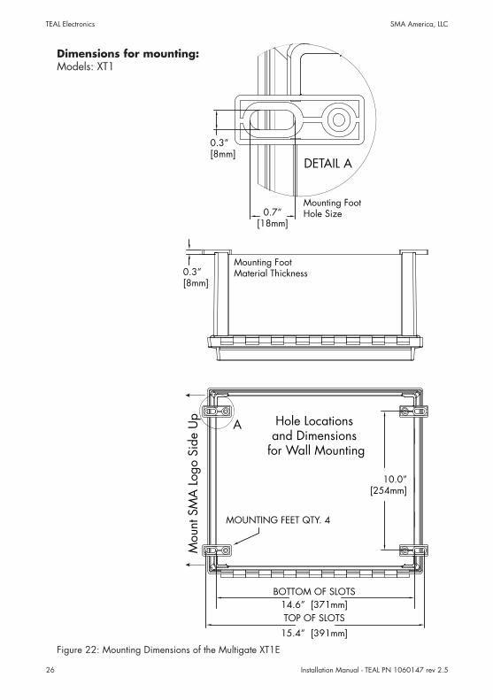
Dimensions for mounting:Models: XT1
Figure 22: Mounting Dimensions of the Multigate XT1E
14.6” [371mm]BOTTOM OF SLOTS
10.0”[254mm]
15.4” [391mm]
TOP OF SLOTS
A
MOUNTING FEET QTY. 4
Hole Locationsand Dimensions
for Wall Mounting
0.7”[18mm]
DETAIL A
0.3”[8mm]
Mounting FootHole Size
0.3”[8mm]
Mounting FootMaterial Thickness
Mou
nt S
MA
Log
o Si
de U
p
Installation Manual - TEAL PN 1060147 rev 2.5 27
TEAL Electronics SMA America, LLC
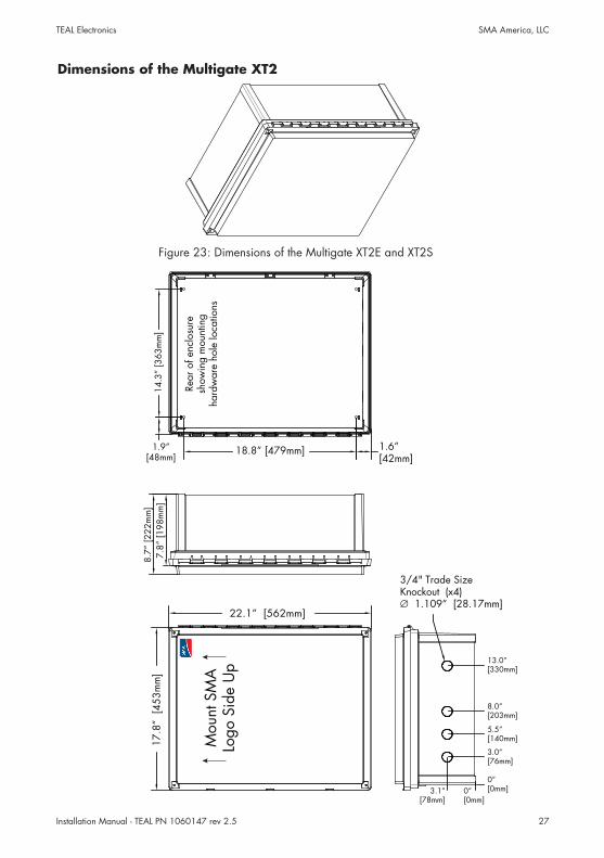
Dimensions of the Multigate XT2
17.8
” [4
53m
m]
22.1” [562mm]
3/4" Trade SizeKnockout (x4)∅ 1.109” [28.17mm]
13.0”[330mm]
8.0”[203mm]
5.5”[140mm]
3.0”[76mm]
0”[0mm]3.1”
[78mm]
8.7”
[222
mm
]7.
8” [1
98m
m]
1.6”[42mm]
18.8” [479mm]1.9”[48mm]
14.3
” [3
63m
m]
Mou
nt S
MA
Logo
Sid
e U
p
0”[0mm]
Rear
of e
nclo
sure
sh
owin
g m
ount
ing
hard
war
e ho
le lo
catio
ns
Figure 23: Dimensions of the Multigate XT2E and XT2S
Installation Manual - TEAL PN 1060147 rev 2.528
TEAL Electronics SMA America, LLC
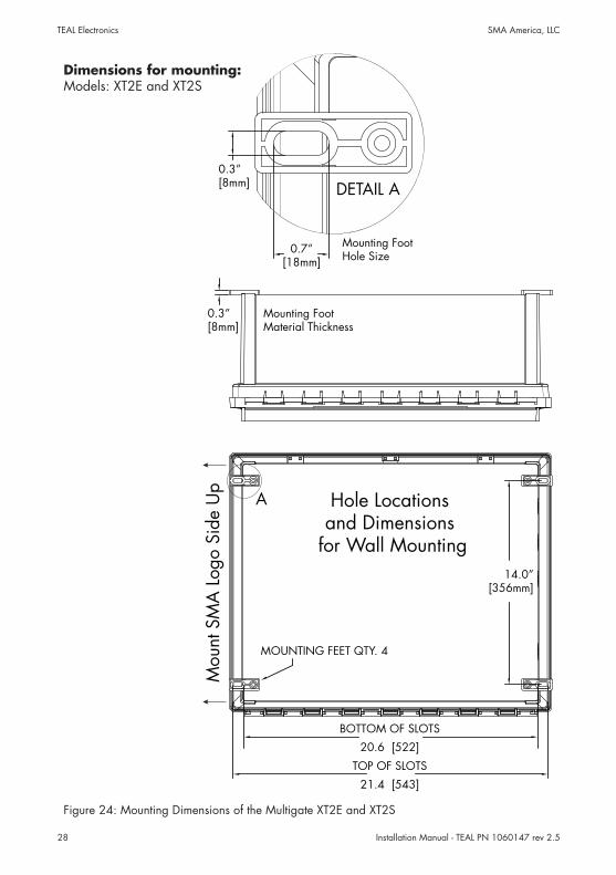
Figure 24: Mounting Dimensions of the Multigate XT2E and XT2S
Dimensions for mounting:Models: XT2E and XT2S
0.7”[18mm]
DETAIL A0.3”[8mm]
20.6 [522]
BOTTOM OF SLOTS
21.4 [543]
TOP OF SLOTS
A
MOUNTING FEET QTY. 4
0.3”[8mm]
14.0”[356mm]
Hole Locationsand Dimensions
for Wall Mounting
Mounting FootHole Size
Mounting FootMaterial Thickness
Mou
nt S
MA
Log
o Si
de U
p
Installation Manual - TEAL PN 1060147 rev 2.5 29
TEAL Electronics SMA America, LLC
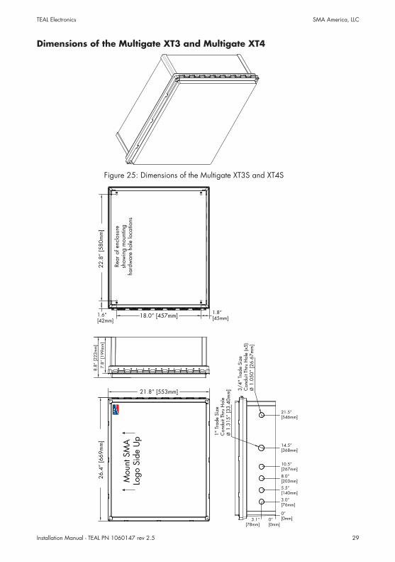
Dimensions of the Multigate XT3 and Multigate XT4
3/4"
Tra
de S
ize
Con
duit
Thru
Hol
e (x
5)Ø
1.0
50”
[26.
67m
m]
1" T
rade
Siz
eC
ondu
it Th
ru H
ole
Ø 1
.315
” [3
3.40
mm
]
21.5”[546mm]
14.5”[368mm]
10.5”[267mm]
8.0”[203mm]
5.5”[140mm]
3.0”[76mm]
0”[0mm]
3.1”[78mm]
8.8”
[222
mm
]
7.8”
[199
mm
]
1.6”[42mm]
22.8
” [5
80m
m]
18.0” [457mm] 1.8”[45mm]
26.4
” [6
69m
m]
21.8” [553mm]
0”[0mm]
Mou
nt S
MA
Logo
Sid
e U
p
Rear
of e
nclo
sure
sh
owin
g m
ount
ing
hard
war
e ho
le lo
catio
ns
Figure 25: Dimensions of the Multigate XT3S and XT4S
Installation Manual - TEAL PN 1060147 rev 2.530
TEAL Electronics SMA America, LLC
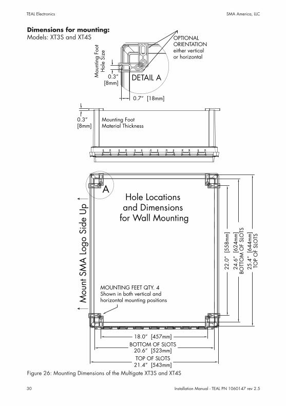
Figure 26: Mounting Dimensions of the Multigate XT3S and XT4S
Dimensions for mounting:Models: XT3S and XT4S
18.0” [457mm]
21.4” [543mm]TOP OF SLOTS
20.6” [523mm]BOTTOM OF SLOTS
25.4
” [6
44m
m]
TOP
OF
SLO
TS
24.6
” [6
24m
m]
BOTT
OM
OF
SLO
TS
22.0
” [5
58m
m]
MOUNTING FEET QTY. 4Shown in both vertical and horizontal mounting positions
A
0.7” [18mm]
0.3”[8mm]
DETAIL A
OPTIONALORIENTATIONeither verticalor horizontal
0.3”[8mm]
Hole Locationsand Dimensions
for Wall Mounting
Mou
nt S
MA
Log
o Si
de U
pM
ount
ing
Foot
Hol
e Si
ze
Mounting FootMaterial Thickness
Installation Manual - TEAL PN 1060147 rev 2.5 31
TEAL Electronics SMA America, LLC
6 Electrical Connection
6.1 Safety during Electrical Connection
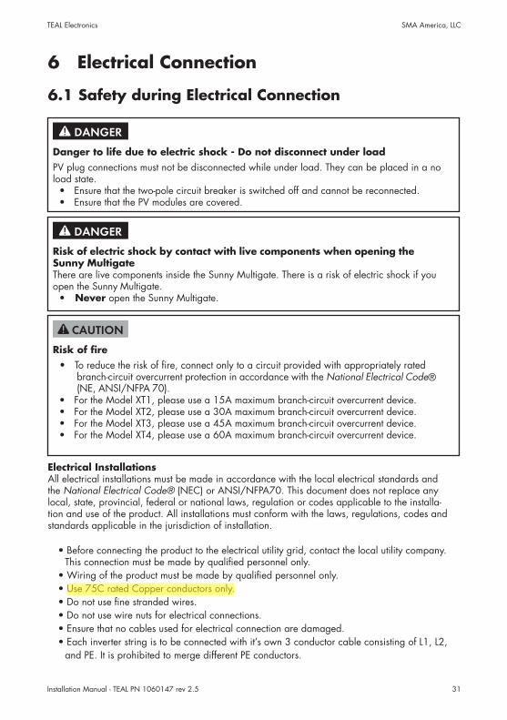
Danger to life due to electric shock - Do not disconnect under loadPV plug connections must not be disconnected while under load. They can be placed in a no load state.
• Ensure that the two-pole circuit breaker is switched off and cannot be reconnected. • Ensure that the PV modules are covered.
Risk of electric shock by contact with live components when opening the Sunny Multigate There are live components inside the Sunny Multigate. There is a risk of electric shock if you open the Sunny Multigate.
• Never open the Sunny Multigate.
Risk of fire• To reduce the risk of fire, connect only to a circuit provided with appropriately rated
branch-circuit overcurrent protection in accordance with the National Electrical Code® (NE, ANSI/NFPA 70).
• For the Model XT1, please use a 15A maximum branch-circuit overcurrent device. • For the Model XT2, please use a 30A maximum branch-circuit overcurrent device. • For the Model XT3, please use a 45A maximum branch-circuit overcurrent device. • For the Model XT4, please use a 60A maximum branch-circuit overcurrent device.
Electrical InstallationsAll electrical installations must be made in accordance with the local electrical standards and the National Electrical Code® (NEC) or ANSI/NFPA70. This document does not replace any local, state, provincial, federal or national laws, regulation or codes applicable to the installa-tion and use of the product. All installations must conform with the laws, regulations, codes and standards applicable in the jurisdiction of installation.
• Before connecting the product to the electrical utility grid, contact the local utility company. This connection must be made by qualified personnel only.
• Wiring of the product must be made by qualified personnel only.• Use 75C rated Copper conductors only.• Do not use fine stranded wires.• Do not use wire nuts for electrical connections.• Ensure that no cables used for electrical connection are damaged.• Each inverter string is to be connected with it’s own 3 conductor cable consisting of L1, L2,
and PE. It is prohibited to merge different PE conductors.
Installation Manual - TEAL PN 1060147 rev 2.532
TEAL Electronics SMA America, LLC
6.2 Connection Areas
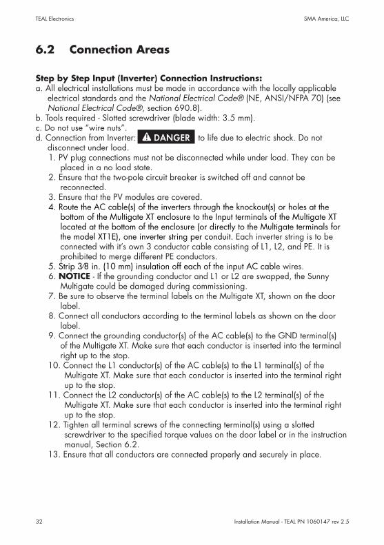
Step by Step Input (Inverter) Connection Instructions:a. All electrical installations must be made in accordance with the locally applicable
electrical standards and the National Electrical Code® (NE, ANSI/NFPA 70) (see National Electrical Code®, section 690.8).
b. Tools required - Slotted screwdriver (blade width: 3.5 mm).c. Do not use “wire nuts”.d. Connection from Inverter: to life due to electric shock. Do not
disconnect under load.1. PV plug connections must not be disconnected while under load. They can be
placed in a no load state.2. Ensure that the two-pole circuit breaker is switched off and cannot be
reconnected.3. Ensure that the PV modules are covered.4. Route the AC cable(s) of the inverters through the knockout(s) or holes at the
bottom of the Multigate XT enclosure to the Input terminals of the Multigate XT located at the bottom of the enclosure (or directly to the Multigate terminals for the model XT1E), one inverter string per conduit. Each inverter string is to be connected with it’s own 3 conductor cable consisting of L1, L2, and PE. It is prohibited to merge different PE conductors.
5. Strip 3⁄8 in. (10 mm) insulation off each of the input AC cable wires.6. NOTICE - If the grounding conductor and L1 or L2 are swapped, the Sunny
Multigate could be damaged during commissioning.7. Be sure to observe the terminal labels on the Multigate XT, shown on the door
label.8. Connect all conductors according to the terminal labels as shown on the door
label.9. Connect the grounding conductor(s) of the AC cable(s) to the GND terminal(s)
of the Multigate XT. Make sure that each conductor is inserted into the terminal right up to the stop.
10. Connect the L1 conductor(s) of the AC cable(s) to the L1 terminal(s) of the Multigate XT. Make sure that each conductor is inserted into the terminal right up to the stop.
11. Connect the L2 conductor(s) of the AC cable(s) to the L2 terminal(s) of the Multigate XT. Make sure that each conductor is inserted into the terminal right up to the stop.
12. Tighten all terminal screws of the connecting terminal(s) using a slotted screwdriver to the specified torque values on the door label or in the instruction manual, Section 6.2.
13. Ensure that all conductors are connected properly and securely in place.
Installation Manual - TEAL PN 1060147 rev 2.5 33
TEAL Electronics SMA America, LLC
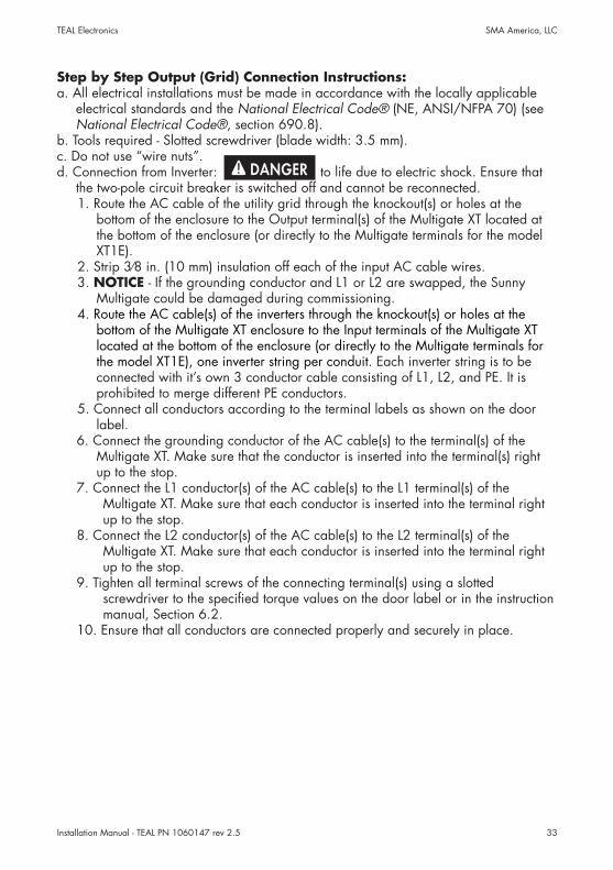
Step by Step Output (Grid) Connection Instructions:a. All electrical installations must be made in accordance with the locally applicable
electrical standards and the National Electrical Code® (NE, ANSI/NFPA 70) (see National Electrical Code®, section 690.8).
b. Tools required - Slotted screwdriver (blade width: 3.5 mm).c. Do not use “wire nuts”.d. Connection from Inverter: to life due to electric shock. Ensure that
the two-pole circuit breaker is switched off and cannot be reconnected.1. Route the AC cable of the utility grid through the knockout(s) or holes at the
bottom of the enclosure to the Output terminal(s) of the Multigate XT located at the bottom of the enclosure (or directly to the Multigate terminals for the model XT1E).
2. Strip 3⁄8 in. (10 mm) insulation off each of the input AC cable wires.3. NOTICE - If the grounding conductor and L1 or L2 are swapped, the Sunny
Multigate could be damaged during commissioning.4. Route the AC cable(s) of the inverters through the knockout(s) or holes at the
bottom of the Multigate XT enclosure to the Input terminals of the Multigate XT located at the bottom of the enclosure (or directly to the Multigate terminals for the model XT1E), one inverter string per conduit. Each inverter string is to be connected with it’s own 3 conductor cable consisting of L1, L2, and PE. It is prohibited to merge different PE conductors.
5. Connect all conductors according to the terminal labels as shown on the door label.
6. Connect the grounding conductor of the AC cable(s) to the terminal(s) of the Multigate XT. Make sure that the conductor is inserted into the terminal(s) right up to the stop.
7. Connect the L1 conductor(s) of the AC cable(s) to the L1 terminal(s) of the Multigate XT. Make sure that each conductor is inserted into the terminal right up to the stop.
8. Connect the L2 conductor(s) of the AC cable(s) to the L2 terminal(s) of the Multigate XT. Make sure that each conductor is inserted into the terminal right up to the stop.
9. Tighten all terminal screws of the connecting terminal(s) using a slotted screwdriver to the specified torque values on the door label or in the instruction manual, Section 6.2.
10. Ensure that all conductors are connected properly and securely in place.
Installation Manual - TEAL PN 1060147 rev 2.534
TEAL Electronics SMA America, LLC
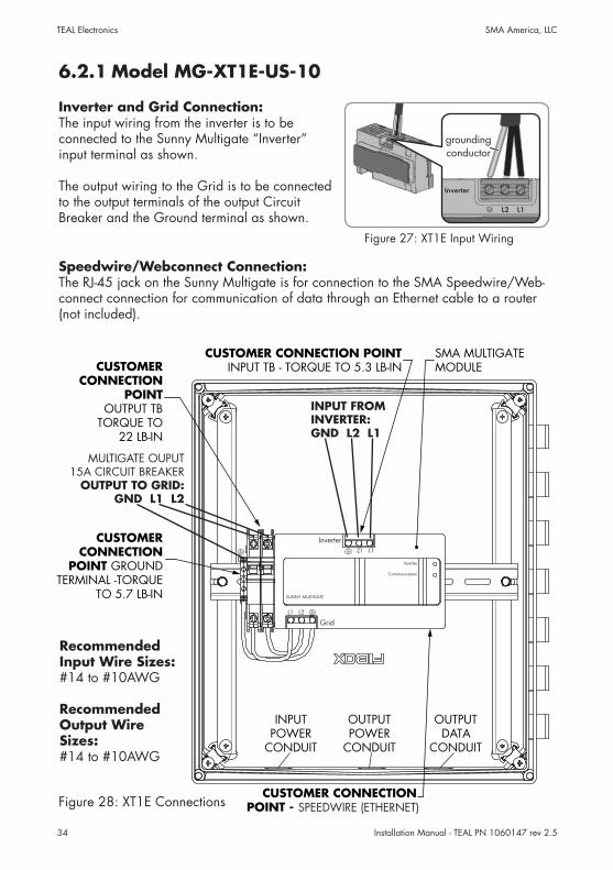
Speedwire/Webconnect Connection:The RJ-45 jack on the Sunny Multigate is for connection to the SMA Speedwire/Web-connect connection for communication of data through an Ethernet cable to a router (not included).
Inverter and Grid Connection:The input wiring from the inverter is to be connected to the Sunny Multigate “Inverter” input terminal as shown.
The output wiring to the Grid is to be connected to the output terminals of the output Circuit Breaker and the Ground terminal as shown.
6.2.1 Model MG-XT1E-US-10
Figure 27: XT1E Input Wiring
INPUT FROM INVERTER:GND L2 L1
MULTIGATE OUPUT15A CIRCUIT BREAKER
OUTPUT TO GRID:GND L1 L2
CUSTOMERCONNECTION
POINT GROUNDTERMINAL -TORQUE
TO 5.7 LB-IN
CUSTOMER CONNECTION POINTINPUT TB - TORQUE TO 5.3 LB-IN
SMA MULTIGATEMODULECUSTOMER
CONNECTIONPOINT
OUTPUT TBTORQUE TO
22 LB-IN
CUSTOMER CONNECTIONPOINT - SPEEDNET (ETHERNET)
Inverter
SUNNY MULTIGATE
Communication
Inverter
GridL1 L2
L1 L2
INPUTPOWER
CONDUIT
OUTPUTPOWER
CONDUIT
OUTPUTDATA
CONDUIT
SPEEDWIRE (ETHERNET)
Recommended Input Wire Sizes: #14 to #10AWG
Recommended Output Wire Sizes: #14 to #10AWG
Figure 28: XT1E Connections
Installation Manual - TEAL PN 1060147 rev 2.5 35
TEAL Electronics SMA America, LLC
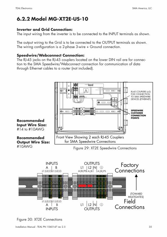
6.2.2 Model MG-XT2E-US-10
Speedwire/Webconnect Connection:The RJ-45 jacks on the RJ-45 couplers located on the lower DIN rail are for connec-tion to the SMA Speedwire/Webconnect connection for communication of data through Ethernet cables to a router (not included).
Inverter and Grid Connection:The input wiring from the inverter is to be connected to the INPUT terminals as shown.
The output wiring to the Grid is to be connected to the OUTPUT terminals as shown. The wiring configuration is a 2-phase 3-wire + Ground connection.
(TOWARDMULTIGATES)
L1|L2| L1|L2|AB
AL1|L2|
BL1|L2|
INPUTS
INPUTS
OUTPUTS
OUTPUTSL1
A|B|PSNL2
L1 L2 N
FactoryConnections
FieldConnections
| | |A B A B PS
B
Recommended Input Wire Size: #14 to #10AWG
Recommended Output Wire Size: #10AWG
RJ-45 COUPLERS (x2)FOR CONNECTIONTO SMA SPEEDWIREDEVICES (ETHERNET)
Inverter
Inverter
Communication
SUNNY MULTIGATE
Grid
L1 L2 G
L1 L2 G
SPEEDWIRECUSTOMERCONNECTIONPOINTS
Front View Showing 2 each RJ-45 Couplersfor SMA Speedwire Connections
Figure 30: XT2E Connections
Figure 29: XT2E Speedwire Connections
Installation Manual - TEAL PN 1060147 rev 2.536
TEAL Electronics SMA America, LLC
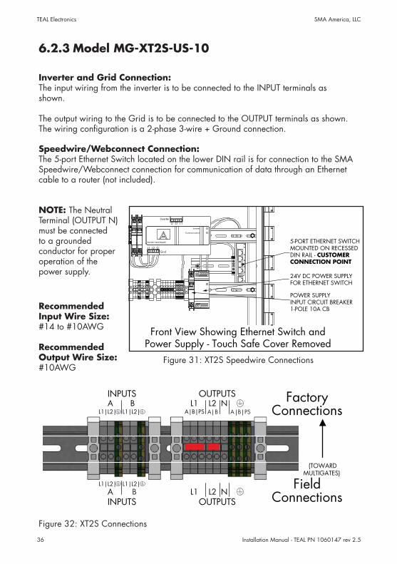
6.2.3 Model MG-XT2S-US-10
Speedwire/Webconnect Connection:The 5-port Ethernet Switch located on the lower DIN rail is for connection to the SMA Speedwire/Webconnect connection for communication of data through an Ethernet cable to a router (not included).
Inverter and Grid Connection:The input wiring from the inverter is to be connected to the INPUT terminals as shown.
The output wiring to the Grid is to be connected to the OUTPUT terminals as shown. The wiring configuration is a 2-phase 3-wire + Ground connection.
(TOWARDMULTIGATES)
L1|L2| L1|L2|AB
AL1|L2|
BL1|L2|
INPUTS
INPUTS
OUTPUTS
OUTPUTSL1
A|B|PSNL2
L1 L2 N
FactoryConnections
FieldConnections
| | |A B A B PS
B
Front View Showing Ethernet Switch andPower Supply - Touch Safe Cover Removed
5-PORT ETHERNET SWITCHMOUNTED ON RECESSEDDIN RAIL - CUSTOMERCONNECTION POINT
24V DC POWER SUPPLYFOR ETHERNET SWITCH
POWER SUPPLYINPUT CIRCUIT BREAKER1-POLE 10A CB
Inverter
Inverter
Communication
SUNNY MULTIGATE
GridL1 L2 G
L1 L2 G
NOTE: The Neutral Terminal (OUTPUT N) must be connected to a grounded conductor for proper operation of the power supply.
Figure 32: XT2S Connections
Figure 31: XT2S Speedwire Connections
Recommended Input Wire Size: #14 to #10AWG
Recommended Output Wire Size: #10AWG
Installation Manual - TEA
L PN 1060147 rev 2.5
37
TEAL Electronics
SMA
Am
erica, LLC
6.2
.4 M
odel M
G-X
T3S-U
S-10
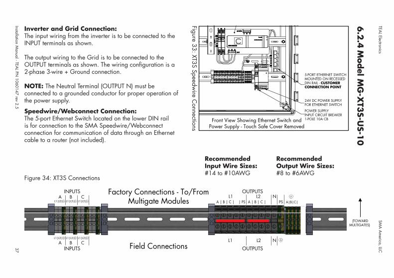
Speedwire/Webconnect Connection:The 5-port Ethernet Switch located on the lower DIN rail is for connection to the SMA Speedwire/Webconnect connection for communication of data through an Ethernet cable to a router (not included).
INPUTS Field ConnectionsL1|L2|
AL1|L2|
BL1|L2|
C
INPUTSA
L1|L2|C
L1|L2|L1
A | B | C | | PSL2
A | B | C | DN
PS A|B|C|D
L1 N
OUTPUTS
OUTPUTSB
L1|L2|
Factory Connections - To/FromMultigate Modules
(TOWARDMULTIGATES)
L2
Recommended RecommendedInput Wire Sizes: Output Wire Sizes: #14 to #10AWG #8 to #6AWG
Inverter and Grid Connection:The input wiring from the inverter is to be connected to the INPUT terminals as shown.
The output wiring to the Grid is to be connected to the OUTPUT terminals as shown. The wiring configuration is a 2-phase 3-wire + Ground connection.
NOTE: The Neutral Terminal (OUTPUT N) must be connected to a grounded conductor for proper operation of the power supply.
Front View Showing Ethernet Switch andPower Supply - Touch Safe Cover Removed
5-PORT ETHERNET SWITCHMOUNTED ON RECESSEDDIN RAIL - CUSTOMERCONNECTION POINT
24V DC POWER SUPPLYFOR ETHERNET SWITCH
POWER SUPPLYINPUT CIRCUIT BREAKER1-POLE 10A CB
Figure 34: XT3S Connections
Figure 33: XT3S Speedwire C
onnections
Installation Manual - TEA
L PN 1060147 rev 2.5
38 TEAL Electronics
SMA
Am
erica, LLC
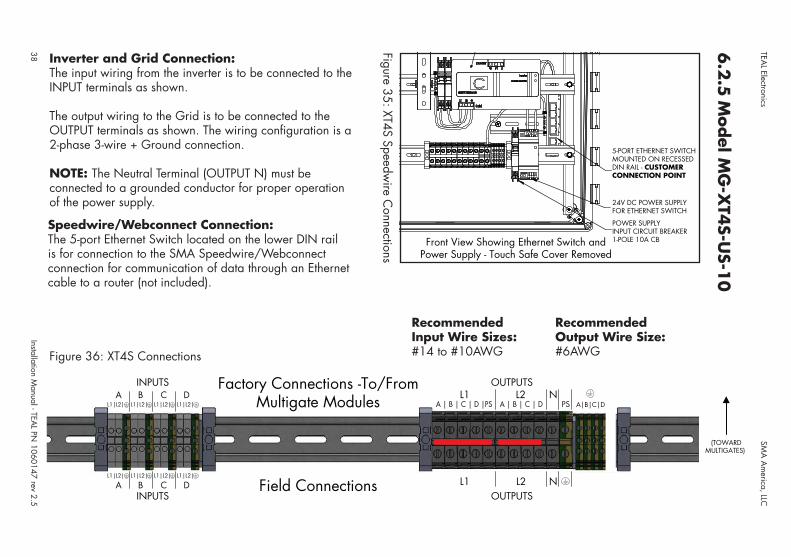
Front View Showing Ethernet Switch andPower Supply - Touch Safe Cover Removed
5-PORT ETHERNET SWITCHMOUNTED ON RECESSEDDIN RAIL - CUSTOMERCONNECTION POINT
24V DC POWER SUPPLYFOR ETHERNET SWITCH
POWER SUPPLYINPUT CIRCUIT BREAKER1-POLE 10A CB
6.2
.5 M
odel M
G-X
T4S-U
S-10
Speedwire/Webconnect Connection:The 5-port Ethernet Switch located on the lower DIN rail is for connection to the SMA Speedwire/Webconnect connection for communication of data through an Ethernet cable to a router (not included).
INPUTSField Connections
L1|L2|
AL1|L2|
BL1|L2|
C
INPUTSA
L1|L2|C
L1|L2|L1
A | B | C | D |PSL2
A | B | C | DN
PS A|B|C|D
L1 NOUTPUTS
OUTPUTSB
L1|L2|
Factory Connections -To/FromMultigate Modules
(TOWARDMULTIGATES)
L2
DL1|L2|
DL1|L2|
Inverter and Grid Connection:The input wiring from the inverter is to be connected to the INPUT terminals as shown.
The output wiring to the Grid is to be connected to the OUTPUT terminals as shown. The wiring configuration is a 2-phase 3-wire + Ground connection.
NOTE: The Neutral Terminal (OUTPUT N) must be connected to a grounded conductor for proper operation of the power supply.
Figure 36: XT4S Connections
Figure 35: XT4S Speedwire C
onnections
Recommended RecommendedInput Wire Sizes: Output Wire Size: #14 to #10AWG #6AWG
Installation Manual - TEAL PN 1060147 rev 2.5 39
TEAL Electronics SMA America, LLC
7.0 Product Specifications
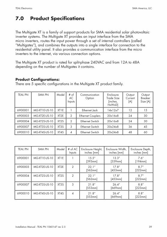
The Multigate XT is a family of support products for SMA residential solar photovoltaic inverter systems. The Multigate XT provides an input interface from the SMA micro inverters, routes the input power through a set of internal controllers (called “Multigates”), and combines the outputs into a single interface for connection to the residential utility panel. It also provides a communication interface from the micro inverters to the internet, via various connection options.
The Multigate XT product is rated for split-phase 240VAC and from 12A to 48A depending on the number of Multigates it contains.
Product Configurations:There are 5 specific configurations in the Multigate XT product family.
TEAL PN SMA PN Model # of AC
Inputs
Communication Option
Enclosure Trade Size
[inches, HxWxD]
Output Current
[A]
Output Breaker Size [A]
6900001 MG-XT1E-US-10 XT1E 1 Ethernet Jack 14x12x7 12 15
6900003 MG-XT2E-US-10 XT2E 2 Ethernet Couplers 20x16x8 24 30
6900004 MG-XT2S-US-10 XT2S 2 Ethernet Switch 20x16x8 24 30
6900007 MG-XT3S-US-10 XT3S 3 Ethernet Switch 20x24x8 36 45
6900010 MG-XT4S-US-10 XT4S 4 Ethernet Switch 20x24x8 48 60
TEAL PN SMA PN Model # of AC Inputs
Enclosure Height, inches [mm]
Enclosure Width, inches [mm]
Enclosure Depth, inches [mm]
6900001 MG-XT1E-US-10 XT1E 1 15.5”[393mm]
13.3”[339mm]
7.6”[194mm]
6900003 MG-XT2E-US-10 XT2E 2 22.1”[562mm]
17.8”[453mm]
8.7”[222mm]
6900004 MG-XT2S-US-10 XT2S 2 22.1”[562mm]
17.8”[453mm]
8.7”[222mm]
6900007 MG-XT3S-US-10 XT3S 3 21.8”[553mm]
26.4”[669mm]
8.8”[223mm]
6900010 MG-XT4S-US-10 XT4S 4 21.8”[553mm]
26.4”[669mm]
8.8”[223mm]

SMA Solar TechnologySMA America, LLC
www.SMA-Solar.com