Embed Size (px)
Citation preview
SC500U-IUS093411 | 98-4014611 | Version 1.1 US
Central InverterSUNNY CENTRAL 500UInstallation Guide


SMA Solar Technology AG
Installation Guide SC500U-IUS093411 3
Copyright © 2009 SMA America, Inc. All rights reserved.No part of this document may be reproduced, stored in a retrieval system, or transmitted, in any form or by any means, electronic, mechanical, photographic, magnetic or otherwise, without the prior written permission of SMA America, Inc.SMA America makes no representations, express or implied, with respect to this documentation or any of the equipment and/or software it may describe, including (with no limitation) any implied warranties of utility, merchantability, or fitness for any particular purpose. All such warranties are expressly disclaimed. Neither SMA America nor its distributors or dealers shall be liable for any indirect, incidental, or consequential damages under any circumstances.(The exclusion of implied warranties may not apply in all cases under some statutes, and thus the above exclusion may not apply.)Specifications are subject to change without notice. Every attempt has been made to make this document complete, accurate and up-to-date. Readers are cautioned, however, that SMA America reserves the right to make changes without notice and shall not be responsible for any damages, including indirect, incidental or consequential damages, caused by reliance on the material presented, including, but not limited to, omissions, typographical errors, arithmetical errors or listing errors in the content material.
SMA America, Incorporated4031 Alvis Court
Rocklin, California 95677-4011Tel 916.625.0870Fax 916.625.0871
www.sma-america.com
SMA Solar Technology AG
4 SC500U-IUS093411 Installation Guide
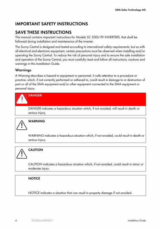
IMPORTANT SAFETY INSTRUCTIONSSAVE THESE INSTRUCTIONSThis manual contains important instructions for Models SC 500U PV INVERTERS, that shall be followed during installation and maintenance of the inverter.The Sunny Central is designed and tested according to international safety requirements, but as with all electrical and electronic equipment, certain precautions must be observed when installing and/or operating the Sunny Central. To reduce the risk of personal injury and to ensure the safe installation and operation of the Sunny Central, you must carefully read and follow all instructions, cautions and warnings in this Installation Guide.WarningsA Warning describes a hazard to equipment or personnel. It calls attention to a procedure or practice, which, if not correctly performed or adhered to, could result in damage to or destruction of part or all of the SMA equipment and/or other equipment connected to the SMA equipment or personal injury.
DANGER
DANGER indicates a hazardous situation which, if not avoided, will result in death or serious injury.
WARNING
WARNING indicates a hazardous situation which, if not avoided, could result in death or serious injury.
CAUTION
CAUTION indicates a hazardous situation which, if not avoided, could result in minor or moderate injury.
NOTICE
NOTICE indicates a situation that can result in property damage if not avoided.

SMA Solar Technology AG
Installation Guide SC500U-IUS093411 5
Other SymbolsIn addition to the safety and hazard symbols described on the previous pages, the following symbol is also used in this Installation Guide:
Markings on this ProductThe following symbols are used as markings on this product with the following meanings.
Information
This symbol accompanies notes that call attention to supplementary information that you should know and use to ensure optimal operation of the system.
Warning regarding dangerous voltageThe product works with high voltages. All work on the product may only be done as described in its documentation.
Beware of hot surfaceThe product can become hot during operation. Avoid coming into contact with the product during operation.
Observe the operating instructionsRead the product’s documentation before working on it. Follow all safety precautions and instructions as described in the documentation.
DC currentEarth Ground
AC current

SMA Solar Technology AG
6 SC500U-IUS093411 Installation Guide
General WarningsGeneral Warnings
All electrical installations must be done in accordance with the local and National Electrical Code ANSI/NFPA 70.The Sunny Central contains no user-serviceable parts. For all repair and maintenance always contact an authorized SMA Service Center.Before installing or using the Sunny Central, read all of the instructions, cautions, and warnings on the Sunny Central, the PV array, in this Installation Guide and in User Manual.Before connecting the Sunny Central to the electrical utility grid, contact the local utility company. This connection must be made only by qualified personnel.PV arrays produce electrical energy when exposed to light and thus can create an electrical shock hazard. Wiring of the PV-arrays shall only be performed by qualified personnel.
SMA Solar Technology AG Table of Contents
Installation Guide SC500U-IUS093411 7
Table of Contents1 Notes on this Manual. . . . . . . . . . . . . . . . . . . . . . . . . . . . . 111.1 Target Group . . . . . . . . . . . . . . . . . . . . . . . . . . . . . . . . . . . . . . 111.2 Validity . . . . . . . . . . . . . . . . . . . . . . . . . . . . . . . . . . . . . . . . . . . 111.3 Structure of this Documentation . . . . . . . . . . . . . . . . . . . . . . . . 112 Safety . . . . . . . . . . . . . . . . . . . . . . . . . . . . . . . . . . . . . . . . . 132.1 Appropriate Usage. . . . . . . . . . . . . . . . . . . . . . . . . . . . . . . . . . 132.2 Safety Instructions . . . . . . . . . . . . . . . . . . . . . . . . . . . . . . . . . . . 143 The Sunny Central . . . . . . . . . . . . . . . . . . . . . . . . . . . . . . . 173.1 System Overview . . . . . . . . . . . . . . . . . . . . . . . . . . . . . . . . . . . 173.2 The Sunny Central's Design. . . . . . . . . . . . . . . . . . . . . . . . . . . . 173.3 Location of the Safety Notices . . . . . . . . . . . . . . . . . . . . . . . . . 183.4 Identifying the Sunny Central . . . . . . . . . . . . . . . . . . . . . . . . . . 193.5 Firmware . . . . . . . . . . . . . . . . . . . . . . . . . . . . . . . . . . . . . . . . . . 194 Unpacking. . . . . . . . . . . . . . . . . . . . . . . . . . . . . . . . . . . . . . 204.1 Unpacking and Inspection . . . . . . . . . . . . . . . . . . . . . . . . . . . . 204.2 Scope of Delivery . . . . . . . . . . . . . . . . . . . . . . . . . . . . . . . . . . . 204.3 Storage . . . . . . . . . . . . . . . . . . . . . . . . . . . . . . . . . . . . . . . . . . . 215 Transport and Installation . . . . . . . . . . . . . . . . . . . . . . . . . 225.1 Choosing the Installation Site . . . . . . . . . . . . . . . . . . . . . . . . . . 225.1.1 Dimensions . . . . . . . . . . . . . . . . . . . . . . . . . . . . . . . . . . . . . . . . . . . . . . . . . . 225.1.2 Weight . . . . . . . . . . . . . . . . . . . . . . . . . . . . . . . . . . . . . . . . . . . . . . . . . . . . . 225.1.3 Ambient Conditions. . . . . . . . . . . . . . . . . . . . . . . . . . . . . . . . . . . . . . . . . . . . 225.1.4 Minimum Clearance . . . . . . . . . . . . . . . . . . . . . . . . . . . . . . . . . . . . . . . . . . . 235.1.5 Characteristics of the Base . . . . . . . . . . . . . . . . . . . . . . . . . . . . . . . . . . . . . . 235.2 Preparation of the Base . . . . . . . . . . . . . . . . . . . . . . . . . . . . . . 245.2.1 Position of the Mounting Holes . . . . . . . . . . . . . . . . . . . . . . . . . . . . . . . . . . . 24
Table of Contents SMA Solar Technology AG
8 SC500U-IUS093411 Installation Guide
5.2.2 Size of the Mounting Holes. . . . . . . . . . . . . . . . . . . . . . . . . . . . . . . . . . . . . . 245.2.3 Drilling Holes into the Base . . . . . . . . . . . . . . . . . . . . . . . . . . . . . . . . . . . . . . 245.3 Transporting the Sunny Central. . . . . . . . . . . . . . . . . . . . . . . . . 255.3.1 Equipment for Transport . . . . . . . . . . . . . . . . . . . . . . . . . . . . . . . . . . . . . . . . 255.3.2 Center of Gravity of the Sunny Central . . . . . . . . . . . . . . . . . . . . . . . . . . . . . 265.4 Installing the Sunny Central . . . . . . . . . . . . . . . . . . . . . . . . . . . 265.4.1 Removing the Kick Plates from the Sunny Central . . . . . . . . . . . . . . . . . . . . . 265.4.2 Inserting the Cables into the Cabinets. . . . . . . . . . . . . . . . . . . . . . . . . . . . . . 285.4.3 Connect the Cables in the Magnetics Cabinet . . . . . . . . . . . . . . . . . . . . . . . 295.4.4 Connecting the Cables in the Control Cabinet . . . . . . . . . . . . . . . . . . . . . . . 315.4.5 Attach the Sunny Central to the base . . . . . . . . . . . . . . . . . . . . . . . . . . . . . . 325.4.6 Install the Cover Between the Cabinets. . . . . . . . . . . . . . . . . . . . . . . . . . . . . 325.4.7 Install Ventilation Plates . . . . . . . . . . . . . . . . . . . . . . . . . . . . . . . . . . . . . . . . . 335.4.8 Attaching the Kick Plates to the Sunny Central . . . . . . . . . . . . . . . . . . . . . . . 345.4.9 Remove Transport Locks . . . . . . . . . . . . . . . . . . . . . . . . . . . . . . . . . . . . . . . . 34
6 Attaching the Conduits. . . . . . . . . . . . . . . . . . . . . . . . . . . . 356.1 Insert cables from the right into the Sunny Central . . . . . . . . . . 356.2 Insert cables from below into the Sunny Central. . . . . . . . . . . . 367 Connecting Optional Communication Devices . . . . . . . . 387.1 Position of the Communication Devices . . . . . . . . . . . . . . . . . . 397.2 Connecting the Sunny SensorBox (optional) . . . . . . . . . . . . . . 397.2.1 Connecting the Data Cable of the Sunny SensorBox . . . . . . . . . . . . . . . . . . 407.3 Sunny WebBox (optional) . . . . . . . . . . . . . . . . . . . . . . . . . . . . 417.3.1 Installing the WebBox in the Sunny Central . . . . . . . . . . . . . . . . . . . . . . . . . 427.3.2 Connecting the Sunny WebBox in the Sunny Central. . . . . . . . . . . . . . . . . . 437.3.3 Connecting the Cable to the Sunny WebBox . . . . . . . . . . . . . . . . . . . . . . . . 437.3.4 Termination . . . . . . . . . . . . . . . . . . . . . . . . . . . . . . . . . . . . . . . . . . . . . . . . . . 43
8 Electrical Connection . . . . . . . . . . . . . . . . . . . . . . . . . . . . . 448.1 Safety . . . . . . . . . . . . . . . . . . . . . . . . . . . . . . . . . . . . . . . . . . . . 448.2 Connection Area. . . . . . . . . . . . . . . . . . . . . . . . . . . . . . . . . . . . 45

SMA Solar Technology AG Table of Contents
Installation Guide SC500U-IUS093411 9
8.3 Connection Options . . . . . . . . . . . . . . . . . . . . . . . . . . . . . . . . . 468.3.1 Grid Types . . . . . . . . . . . . . . . . . . . . . . . . . . . . . . . . . . . . . . . . . . . . . . . . . . 468.3.2 DC Fuses . . . . . . . . . . . . . . . . . . . . . . . . . . . . . . . . . . . . . . . . . . . . . . . . . . . . 468.3.3 Grounding the PV modules . . . . . . . . . . . . . . . . . . . . . . . . . . . . . . . . . . . . . . 468.4 Requirements for Connecting cables to Rails . . . . . . . . . . . . . . 478.4.1 Prepare Cables for Connecting to Rails . . . . . . . . . . . . . . . . . . . . . . . . . . . . 488.5 Connection of the PV Modules . . . . . . . . . . . . . . . . . . . . . . . . . 498.5.1 Requirements. . . . . . . . . . . . . . . . . . . . . . . . . . . . . . . . . . . . . . . . . . . . . . . . . 498.5.2 Connecting the PV Modules . . . . . . . . . . . . . . . . . . . . . . . . . . . . . . . . . . . . . 508.6 AC Connection . . . . . . . . . . . . . . . . . . . . . . . . . . . . . . . . . . . . . 528.6.1 Requirements. . . . . . . . . . . . . . . . . . . . . . . . . . . . . . . . . . . . . . . . . . . . . . . . . 528.6.2 Connecting AC . . . . . . . . . . . . . . . . . . . . . . . . . . . . . . . . . . . . . . . . . . . . . . . 53
9 Commissioning . . . . . . . . . . . . . . . . . . . . . . . . . . . . . . . . . . 559.1 Visual Inspection of the Sunny Central . . . . . . . . . . . . . . . . . . . 559.2 Switching the Sunny Central On. . . . . . . . . . . . . . . . . . . . . . . . 569.3 Check the Ventilation . . . . . . . . . . . . . . . . . . . . . . . . . . . . . . . . 5810 Opening the Sunny Central. . . . . . . . . . . . . . . . . . . . . . . . 6010.1 Opening the Control Cabinet . . . . . . . . . . . . . . . . . . . . . . . . . . 6010.2 Opening the Interface Cabinet . . . . . . . . . . . . . . . . . . . . . . . . . 6110.3 Opening the Magnetics Cabinet . . . . . . . . . . . . . . . . . . . . . . . 6211 Maintenance. . . . . . . . . . . . . . . . . . . . . . . . . . . . . . . . . . . . 6311.1 Sunny Central Maintenance Work . . . . . . . . . . . . . . . . . . . . . . 6311.2 Replace DC fuse . . . . . . . . . . . . . . . . . . . . . . . . . . . . . . . . . . . . 6312 Parameter . . . . . . . . . . . . . . . . . . . . . . . . . . . . . . . . . . . . . . 6412.1 Parameter Description. . . . . . . . . . . . . . . . . . . . . . . . . . . . . . . . 6412.2 Changing Parameters . . . . . . . . . . . . . . . . . . . . . . . . . . . . . . . . 6813 Technical Data . . . . . . . . . . . . . . . . . . . . . . . . . . . . . . . . . . 6913.1 Measurement Accuracy . . . . . . . . . . . . . . . . . . . . . . . . . . . . . . 71
Table of Contents SMA Solar Technology AG
10 SC500U-IUS093411 Installation Guide
14 Contact . . . . . . . . . . . . . . . . . . . . . . . . . . . . . . . . . . . . . . . . 7215 Appendix - Celsius to Fahrenheit conversion. . . . . . . . . . 73

SMA Solar Technology AG
Installation Guide SC500U-IUS093411 11
1 Notes on this ManualThis manual describes the installation and the commissioning of a Sunny Central 500U with 6, 7, 8 and 9 DC fuses. This manual does not cover any details concerning PV modules. Information concerning the PV modules is available from the manufacturer of the PV modules.
1.1 Target GroupThis manual is for qualified personnel. Qualified personnel has received training and has demonstrated skills and knowledge in the construction and operation of the device. Qualified personnel is trained to deal with the dangers and hazards in-raumvolved in installing electric devices.
1.2 ValidityThis manual is valid for the Sunny Central 500U. In this manual the Sunny Central 500U is referred to as "Sunny Central".
1.3 Structure of this DocumentationThe Sunny Central's installation comprises several steps. Here we will describe the contents you will find in the sections of the installation instructions.The instructions are divided into the following sections:Section 2: SafetyIn this section you will find general safety directions which you must observe throughout the entire installation process. Pay special attention to this section, so as to avoid personal and material damages.Section 3: The Sunny CentralIn this section you will see how one can identify the Sunny Central. A short description of the Sunny Central's design and functions are given here.Section 4: UnpackingThis section describes what to look out for upon receiving your Sunny Central, and who to turn to if your Sunny Central is damaged. Section 5: Transport and InstallationThis section shows you how to find the best installation site for your Sunny Central. It provides step-by-step instructions on how to transport and install the Sunny Central and connect the cabinets with each other electrically. Observe all safety precautions in this section to avoid material and personal damages.Section 6: Attaching the ConduitsThis section describes where to insert the cables in the Sunny Central and where to punch the holes for the conduits.
SMA Solar Technology AG
12 SC500U-IUS093411 Installation Guide
Section 7: Connecting the Sunny WebBoxThe Sunny Central can be equipped with a Sunny WebBox and/or a Sunny SensorBox. This section explains how the Sunny WebBox and the Sunny Sensor Box in the Sunny Central is connected.Section 8: Electrical ConnectionThis section describes how the Sunny Central is connected to the grid and to the PV modules, and what precautions must be observed in order to avoid material and personal damages. It provides information on the necessary cable sizes and the magnitude of the torque for the cable connection. Section 9: CommissioningThis section explains, step-by-step, how to put the Sunny Central into operation, and how you can determine that the commissioning was successful.Section 10: Opening the Sunny CentralThis section describes how to open the Sunny Central and what precautions must be observed in order to avoid personal damages. Section 11: MaintenanceThe Sunny Central inverter must be maintained at regular intervals. This section describes which works are included in maintenance and in which intervalls the maintenance works have to be done.Section 12: ParameterThis section provides an overview of the parameters of the Sunny Central and their respective threshold values.Section 13: Technical DataIn this section you will find the technical data for the Sunny Central's operation, the norms to which it conforms and the required cables and torques.

SMA Solar Technology AG
Installation Guide SC500U-IUS093411 13
2 SafetyIn this section you will find general safety directions which you must observe throughout the entire installation process. Pay special attention to this section, so as to avoid personal and material damages.
2.1 Appropriate UsageThe Sunny Central is a MPPT (maximum power point tracker) PV inverter that converts the DC energy from PV modules to AC energy. This energy is then fed to the public grid. The Sunny Central 500U is designed for indoor and outdoor installation.Principle of a PV Power System with a Sunny Central
Any other application of the Sunny Central or installation of components and modifications which are not explicitly allowed endanger the safety and void the warranty as well as the operation permit.
Position DescriptionA PV modulesB DC distribution with DC fuses (e.g., Sunny Central String-Monitor)C DC disconnectD Sunny CentralE AC fuseF AC disconnectG Public grid
A B
C D F GE
Stop Start

SMA Solar Technology AG
14 SC500U-IUS093411 Installation Guide
It is prohibited: • to use the Sunny central for purposes other than those described here.• to connect voltage sources to the Sunny Central other than those consisting of PV modules.• to modify the Sunny Central or to install components that are not explicitly recommended by
SMA America or sold by SMA America for this purpose.
2.2 Safety InstructionsDANGER
High voltages are present in the live components of the low voltage gridDeath resulting from burning and electric shock.
• Do not touch the live components of the Sunny Central or low-voltage grid.• Pay close attention to all safety precaution measures regarding the low voltage grid.
DANGER
During operation, high voltages are present in the Sunny Central.Death resulting from electric shock.
• Do not operate the Sunny Central with doors open.
DANGER
During operation, high voltages are present in the Sunny Central.Death resulting from electric shock.Before commencing work on the Sunny Central:
• Disconnect completely.• Ensure that the device cannot be reconnected.• Ensure that no voltage is present.• Ground and short-circuit.• Cover any nearby live parts.

SMA Solar Technology AG
Installation Guide SC500U-IUS093411 15
DANGER
Normally grounded conductors may be ungrounded and energized when a ground-fault is indicated.Risk of electric shock.
• Test before touching.• Work on the Sunny Central must be carried out by qualified personnel.
WARNING
Failure to follow the manual, the operating instructions and the safety precautions may lead to severe injury from electric shock.
• All work on the Sunny Central shall only be done as described in this manual.• Pay attention to all safety instructions.• Follow all operating instructions.• If problems occur when performing the work described here, contact SMA America.
WARNING
Operating a damaged Sunny Central may cause severe injury from electric shock.• The Sunny Central shall only be used when it is technically faultless and safe to
operate.• Operate the Sunny Central only if there are no visible damages.• Regularly check the Sunny Central for visible damage.• Ensure that all safety features are accessible at all times and that their correct
operation is tested regularly.
CAUTION
Cuts and scratches due to sharp edges inside the Sunny Central.• When working on the Sunny Central wear protective gloves.

SMA Solar Technology AG
16 SC500U-IUS093411 Installation Guide
NOTICE
The components in the Sunny Central can be damaged by electrostatic discharge.• When working on the Sunny Central and when handling the components observe all
ESD safety regulations.• Discharge electrostatic charge by touching the grounded Sunny Central enclosure.
Storage of handbooks
Keep this documentation in the immediate vicinity of the Sunny Central. It must be accessible to service and maintenance personnel at any time.Do not store the documentation or any other papers in the Sunny Central.

SMA Solar Technology AG
Installation Guide SC500U-IUS093411 17
3 The Sunny Central In this section you will see how one can identify the Sunny Central. A short description of the Sunny Central's design and functions are given here.
3.1 System OverviewThe Sunny Central is an inverter for indoor and outdoor. The enclosure is made of steel which has been zinc plated and coated and which conforms to the NEMA 3R protection rating. NEMA 3R means that the Sunny Central is protected against dust and water and chemical aggressiv environment when it is closed. Operating PrinciplesThe PV modules convert a portion of sunlight into electrical energy (direct current). The Sunny Central then converts the direct current into alternating current and feeds it into the public grid. This current can be used directly, or it can be sold to your energy provider.
3.2 The Sunny Central's Design The Sunny Central is divided into three sections.
Position DescriptionA Magnetics Cabinet: The Sunny Central's transformer is contained in the
Magnetics Cabinet.B Control Cabinet: The control cabinet contains the system control, the Sunny
Display, the stop/start switch and the power units for converting direct current to alternating current.
C Interface Cabinet: All AC, DC and data cables are connected in the interface cabinet (see also Section 8.2 "Connection Area" (page 45)).
A B C

SMA Solar Technology AG
18 SC500U-IUS093411 Installation Guide
3.3 Location of the Safety NoticesThe figure to the right shows the location of the safety notices on the Sunny Central.
Position DescriptionA Magnetics Cabinet door
General Warnings.B Control Cabinet door and Interface
Cabinet doorWarning regarding high voltages in the Sunny Central.
C Open Magnetics Cabinet, capacitorWarning regarding high voltages. Capacitor and plate are not grounded.
D Open Magnetices CabinetBeware of hot surfaces.
E Open Magnetices CabinetType plate
F Control Cabinet left doorMaximum ambient temperature.
G Control Cabinet left doorWarning regarding ground-fault.
H Open Interface Cabinet, left sideType plate
I Open Interface CabinetBeware of hot surfaces.

SMA Solar Technology AG
Installation Guide SC500U-IUS093411 19
3.4 Identifying the Sunny CentralYou can identify the Sunny Central using the type plate (see figure at right). The type plate is on the inside of the Interface Cabinet.
3.5 FirmwareThe Sunny Central's firmware, and that of the display, are shown on the display of the Sunny Central. The Sunny Central’s user manual describes how to obtain the firmware version.
Position DescriptionA Type description of the Sunny CentralB Serial number of the Sunny CentralC Fabrication VersionD Fabrication Date
SMA Solar Technology AG
www.sma-america.com
SUNNY CENTRAL
Model: Serial No.:
SC500U 0180100000
Fabrication Date:
Max. Continuous output Power*
Operating voltage range (Vac 3-Phase)*
Min
422
Operating frequency range (Hz)*
Max. continuous output current*
Range of input operating voltage
MPPT Range of operating DC voltage*
Utility interactive inverterLISTED UL 1741 36AN
500kWac
Nominal Max
480 522
Min
59.3
Nominal Max
60.0 60.5
601,4Aac
Output power factor 0.99-1,0
290 - 600 Vdc
The unit contains DC-Ground and Fault Detectorand Interruptor
Max. operating current*
300 - 600 Vdc
1600 Adc
ENCLOSURE Type 3R (IP54)
*For more details and for tightening torque,allowable wire size and type see the Operator’sManual
Utility Interactive 3-Phase Inverter
Tested To ComplyWith FCC Standards
FOR HOME AND OFFICE USE
08/2009
A
B
CFabrication Version: P02
D
SMA Solar Technology AG
20 SC500U-IUS093411 Installation Guide
4 UnpackingThis section describes what to look out for upon receiving your Sunny Central, and who to turn to if your Sunny Central is damaged.
4.1 Unpacking and InspectionAll SMA Sunny Centrals are thoroughly checked before they are packaged and shipped. Although they are shipped in sturdy packaging, damage can still occur during shipping and delivery. It is important to carefully inspect the shipping container and contents prior to installation. If you detect any external damage after unpacking, report the damage immediately to your SMA dealer and shipping company that delivered the unit. If it becomes necessary to return the Sunny Central, use the original packing material.If you need assistance with a damaged Sunny Central, contact your SMA dealer or SMA America. Contact information for SMA America is provided below.
SMA America, Incorporated 4031 Alvis Court
Rocklin, California 95677-4011Tel.: 916-625-0870 Fax: 916-625-0871
www.sma-america.com

SMA Solar Technology AG
Installation Guide SC500U-IUS093411 21
4.2 Scope of Delivery
4.3 Storage
Position DescriptionA Magnetics CabinetB Interface and Control CabinetC Cover for the cables between the cabinets of the Sunny Central and screwsD Condensate drainE Installation Guide, User Manual, Circuit Diagram, Test ReportF Torx screwdriverG Sealing splintsH U-shaped plateI Ventilation plate with air filters for installation in the base of the Sunny CentralJ Non-woven abrasiveK Allen key
NOTICE
Improper storage can cause moisture to seep into the Sunny Central.Damage to the Sunny Central.
• The Sunny Central must be closed during storage.• If stored for 6 months or longer, make sure the storage area is dry.
Central Inverter250U
Installation Guide
SUNNY CENTRAL
Central Inverter250U
Installation Guide
SUNNY CENTRAL SMASMA
Central Inverter250U
Installation Guide
SUNNY CENTRAL
Central Inverter250U
Installation Guide
SUNNY CENTRAL SMASMA
Central Inverter250U
Installation Guide
SUNNY CENTRAL
Central Inverter250U
Installation Guide
SUNNY CENTRAL SMASMA
Central Inverter250U
Installation Guide
SUNNY CENTRAL
Central Inverter250U
Installation Guide
SUNNY CENTRAL SMASMA
C D E
F G H
A B
I J
Stop Start
K
SMA Solar Technology AG
22 SC500U-IUS093411 Installation Guide
5 Transport and InstallationThis section shows you how to find the best installation site for your Sunny Central. It provides step-by-step instructions on how to transport and install the Sunny Central and connect the cabinets with each other electrically. Observe all safety precautions in this section to avoid material and personal damages.
5.1 Choosing the Installation Site
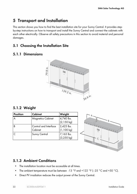
5.1.1 Dimensions
5.1.2 Weight
5.1.3 Ambient Conditions• The installation location must be accessible at all times.• The ambient temperature must be between -13 °F and +122 °F (–25 °C and +50 °C).• Direct PV irradiation reduces the output power of the Sunny Central.
Position Cabinet WeightA Magnetics Cabinet 4,740 lbs.
(2,150 kg)B Control and Interface
Cabinet2,425 lbs. (1,100 kg)
C Sunny Central 7,165 lbs. (3,250 kg)
79
.8 in
.
139.2 in.
36.6 in.
Stop Start
A
B
C

SMA Solar Technology AG
Installation Guide SC500U-IUS093411 23
• For installing the Sunny Central in closed rooms an air supply of 2090 CFM (3,550 m³ /h) is needed.
• For more information see section 13 "Technical Data" (page 69).
5.1.4 Minimum ClearanceObserve the specified minimum clearances for the cables, ventilation and for opening the doors. For installing the Sunny Central in closed rooms an air supply of 2090 CFM (3,550 m³ /h) is needed.
5.1.5 Characteristics of the Base• The foundation must be made of concrete.• The mounting surface must be level and strong
enough to support the weight of the inverter. The evenness of the foundation must be less than 0.25 %.
• The width and depth of the base must be at least the same size as the Sunny Central.
• To insert the cables from below, the cable conduits must be laid in the foundation (see section 6.2 "Insert cables from below into the Sunny Central" (page 36)).
Position Cables inserted from ... Minimum clearanceA below 6 in. (15 cm)B the side 47 in. (120 cm)
6 in.6 in.
47 in. 47 in.
6 in.
16 in.
Stop Start
A
B
min. 145 in.min. 4
0 in.
Stop Start

SMA Solar Technology AG
24 SC500U-IUS093411 Installation Guide
5.2 Preparation of the BaseThe inverter must be secured to the foundation per local building codes. At the bottom of the Sunny Central there are 12 mounting holes for anchoring it to its base.
5.2.1 Position of the Mounting Holes
5.2.2 Size of the Mounting Holes
5.2.3 Drilling Holes into the Base
1. Measure the distances for the holes.2. Mark the positions of the holes.3. Drill the holes into the base on marked positions.4. Put anchor studs into the drill holes.
DANGER
Drilling into live wires.Death resulting from electric shock.
• Check the installation location for electric cables laid in the base.
40.3 in.
31
.1 in
.
47.1 in.12.5 in. 29.4 in.
4.1 in.7.9 in.
0.5 in.
1.4 in.
SMA Solar Technology AG
Installation Guide SC500U-IUS093411 25
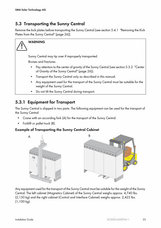
5.3 Transporting the Sunny CentralRemove the kick plates before transporting the Sunny Central (see section 5.4.1 "Removing the Kick Plates from the Sunny Central" (page 26)).
5.3.1 Equipment for TransportThe Sunny Central is shipped in two parts. The following equipment can be used for the transport of the Sunny Central:
• Crane with an according fork (A) for the transport of the Sunny Central.• Forklift or pallet truck (B).
Example of Transporting the Sunny Central Cabinet
Any equipment used for the transport of the Sunny Central must be suitable for the weight of the Sunny Central. The left cabinet (Magnetics Cabinet) of the Sunny Central weighs approx. 4,740 lbs. (2,150 kg) and the right cabinet (Control and Interface Cabinet) weighs approx. 2,425 lbs. (1,100 kg).
WARNING
Sunny Central may tip over if improperly transported.Bruises and fractures.
• Pay attention to the center of gravity of the Sunny Central (see section 5.3.2 "Center of Gravity of the Sunny Central" (page 26)).
• Transport the Sunny Central only as described in this manual.• Any equipment used for the transport of the Sunny Central must be suitable for the
weight of the Sunny Central.• Do not tilt the Sunny Central during transport.
Stop Start
A B
SMA Solar Technology AG
26 SC500U-IUS093411 Installation Guide
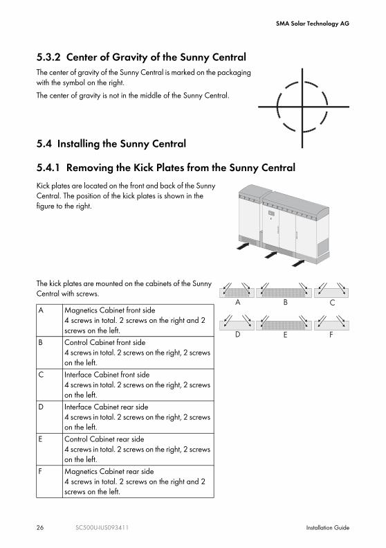
5.3.2 Center of Gravity of the Sunny CentralThe center of gravity of the Sunny Central is marked on the packaging with the symbol on the right.The center of gravity is not in the middle of the Sunny Central.
5.4 Installing the Sunny Central
5.4.1 Removing the Kick Plates from the Sunny Central
The kick plates are mounted on the cabinets of the Sunny Central with screws.
Kick plates are located on the front and back of the Sunny Central. The position of the kick plates is shown in the figure to the right.
A Magnetics Cabinet front side4 screws in total. 2 screws on the right and 2 screws on the left.
B Control Cabinet front side4 screws in total. 2 screws on the right, 2 screws on the left.
C Interface Cabinet front side4 screws in total. 2 screws on the right, 2 screws on the left.
D Interface Cabinet rear side4 screws in total. 2 screws on the right, 2 screws on the left.
E Control Cabinet rear side4 screws in total. 2 screws on the right, 2 screws on the left.
F Magnetics Cabinet rear side4 screws in total. 2 screws on the right and 2 screws on the left.
Stop Start
A CB
D E F
SMA Solar Technology AG
Installation Guide SC500U-IUS093411 27
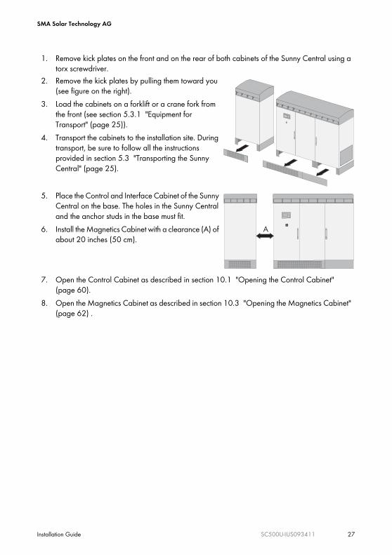
1. Remove kick plates on the front and on the rear of both cabinets of the Sunny Central using a torx screwdriver.
2. Remove the kick plates by pulling them toward you (see figure on the right).
3. Load the cabinets on a forklift or a crane fork from the front (see section 5.3.1 "Equipment for Transport" (page 25)).
4. Transport the cabinets to the installation site. During transport, be sure to follow all the instructions provided in section 5.3 "Transporting the Sunny Central" (page 25).
5. Place the Control and Interface Cabinet of the Sunny Central on the base. The holes in the Sunny Central and the anchor studs in the base must fit.
6. Install the Magnetics Cabinet with a clearance (A) of about 20 inches (50 cm).
7. Open the Control Cabinet as described in section 10.1 "Opening the Control Cabinet" (page 60).
8. Open the Magnetics Cabinet as described in section 10.3 "Opening the Magnetics Cabinet" (page 62) .
Stop Start
A
SMA Solar Technology AG
28 SC500U-IUS093411 Installation Guide
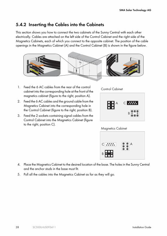
5.4.2 Inserting the Cables into the CabinetsThis section shows you how to connect the two cabinets of the Sunny Central with each other electrically. Cables are attached on the left side of the Control Cabinet and the right side of the Magnetics Cabinets, each of which you connect to the opposite cabinet. The position of the cable openings in the Magnetics Cabinet (A) and the Control Cabinet (B) is shown in the figure below.
1. Feed the 6 AC cables from the rear of the control cabinet into the corresponding hole at the front of the magnetics cabinet (figure to the right, position A).
2. Feed the 6 AC cables and the ground cable from the Magnetics Cabinet into the corresponding hole in the Control Cabinet (figure to the right, position B).
3. Feed the 2 sockets containing signal cables from the Control Cabinet into the Magnetics Cabinet (figure to the right, position C).
4. Place the Magnetics Cabinet to the desired location of the base. The holes in the Sunny Central and the anchor studs in the base must fit.
5. Pull all the cables into the Magnetics Cabinet as far as they will go.
Stop Start
Control Cabinet
Magnetics Cabinet
A
B
C
A C
B
SMA Solar Technology AG
Installation Guide SC500U-IUS093411 29
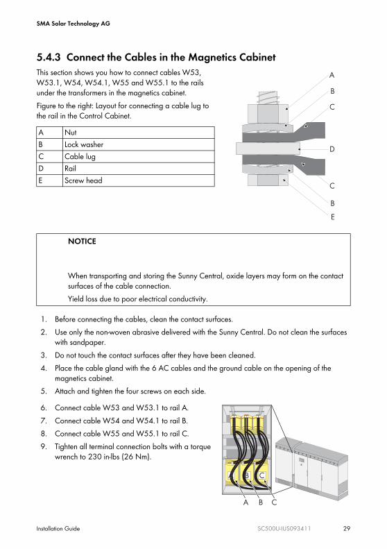
5.4.3 Connect the Cables in the Magnetics CabinetThis section shows you how to connect cables W53, W53.1, W54, W54.1, W55 and W55.1 to the rails under the transformers in the magnetics cabinet.Figure to the right: Layout for connecting a cable lug to the rail in the Control Cabinet.
1. Before connecting the cables, clean the contact surfaces.2. Use only the non-woven abrasive delivered with the Sunny Central. Do not clean the surfaces
with sandpaper.3. Do not touch the contact surfaces after they have been cleaned.4. Place the cable gland with the 6 AC cables and the ground cable on the opening of the
magnetics cabinet.5. Attach and tighten the four screws on each side.
A NutB Lock washerC Cable lugD RailE Screw head
NOTICE
When transporting and storing the Sunny Central, oxide layers may form on the contact surfaces of the cable connection.Yield loss due to poor electrical conductivity.
6. Connect cable W53 and W53.1 to rail A.7. Connect cable W54 and W54.1 to rail B.8. Connect cable W55 and W55.1 to rail C.9. Tighten all terminal connection bolts with a torque
wrench to 230 in-lbs (26 Nm).
A
B
C
D
C
B
E
A B C
A B C
Stop Start
SMA Solar Technology AG
30 SC500U-IUS093411 Installation Guide
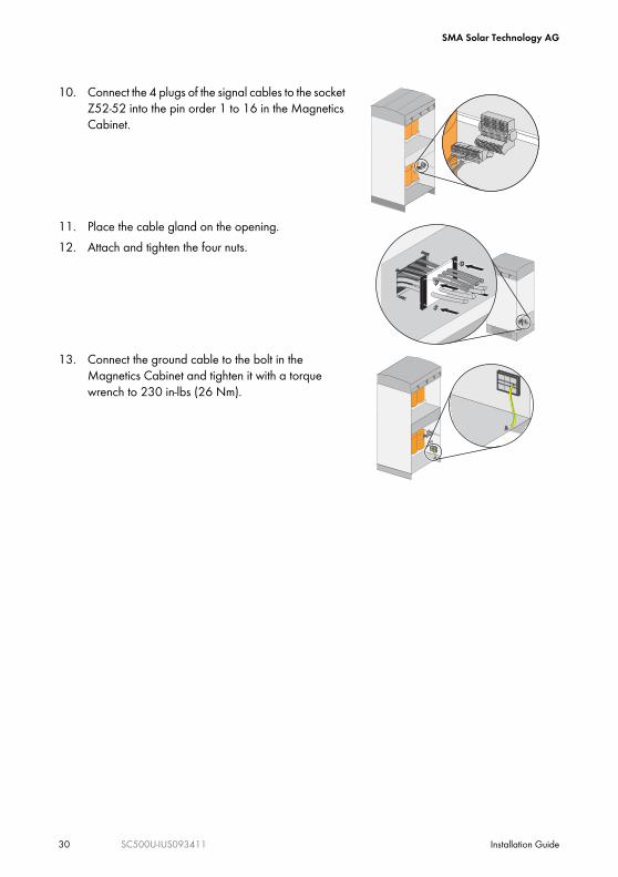
10. Connect the 4 plugs of the signal cables to the socket Z52-52 into the pin order 1 to 16 in the Magnetics Cabinet.
11. Place the cable gland on the opening.12. Attach and tighten the four nuts.
13. Connect the ground cable to the bolt in the Magnetics Cabinet and tighten it with a torque wrench to 230 in-lbs (26 Nm).
1010 11 1212 1313 1414 1515 16
2
7 9
17 1818 1919 20
8
1 3 4 5 6
1010 11 1212 1313 1414 1515 1616
1 2 3 4 5 6 7 9
1717 1818 1919 2020
8
1010
2
7 98
1 3 4 5 6
1010
2
7 98
1 3 4 5 6
1010 11 1212 1313 1414 1515 1616
2
7 9
1717 1818 1919 2020
8
1 3 4 5 6
1010 11 1212 1313 1414 1515 1616
1 2 3 4 5 6 7 9
1717 1818 1919 2020
8
1010
2
7 98
1 3 4 5 6
1010
2
7 98
1 3 4 5 6
SMA Solar Technology AG
Installation Guide SC500U-IUS093411 31
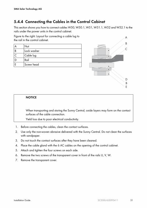
5.4.4 Connecting the Cables in the Control CabinetThis section shows you how to connect cables W50, W50.1, W51, W51.1, W52 and W52.1 to the rails under the power units in the control cabinet. Figure to the right: Layout for connecting a cable lug to the rail in the control cabinet.
1. Before connecting the cables, clean the contact surfaces.2. Use only the non-woven abrasive delivered with the Sunny Central. Do not clean the surfaces
with sandpaper.3. Do not touch the contact surfaces after they have been cleaned.4. Place the cable gland with the 6 AC cables on the opening of the control cabinet.5. Attach and tighten the four screws on each side.6. Remove the two screws of the transparent cover in front of the rails U, V, W.7. Remove the transparent cover.
A NutB Lock washerC Cable lugD RailE Screw head
NOTICE
When transporting and storing the Sunny Central, oxide layers may form on the contact surfaces of the cable connection.Yield loss due to poor electrical conductivity.
A
B
C
D
EB
SMA Solar Technology AG
32 SC500U-IUS093411 Installation Guide
5.4.5 Attach the Sunny Central to the base
5.4.6 Install the Cover Between the Cabinets
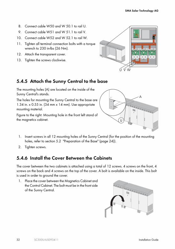
8. Connect cable W50 and W 50.1 to rail U.9. Connect cable W51 and W 51.1 to rail V.
10. Connect cable W52 and W 52.1 to rail W.11. Tighten all terminal connection bolts with a torque
wrench to 230 in-lbs (26 Nm).12. Attach the transparent cover.13. Tighten the screws clockwise.
The mounting holes (A) are located on the inside of the Sunny Central's stands.The holes for mounting the Sunny Central to the base are 1.34 in. x 0.55 in. (34 mm x 14 mm). Use appropriate mounting material.Figure to the right: Mounting hole in the front left stand of the magnetics cabinet.
1. Insert screws in all 12 mounting holes of the Sunny Central (for the position of the mounting holes, refer to section 5.2 "Preparation of the Base" (page 24)).
2. Tighten screws.
The cover between the two cabinets is attached using a total of 12 screws. 4 screws on the front, 4 screws on the back and 4 screws on the top of the cover. A bolt is available on the inside. This bolt is used in order to ground the cover.1. Place the cover between the Magnetics Cabinet and
the Control Cabinet. The bolt must be in the front side of the Sunny Central.
L-
L+
U V W
L+
L+
A
Stop Start
Stop Start
SMA Solar Technology AG
Installation Guide SC500U-IUS093411 33
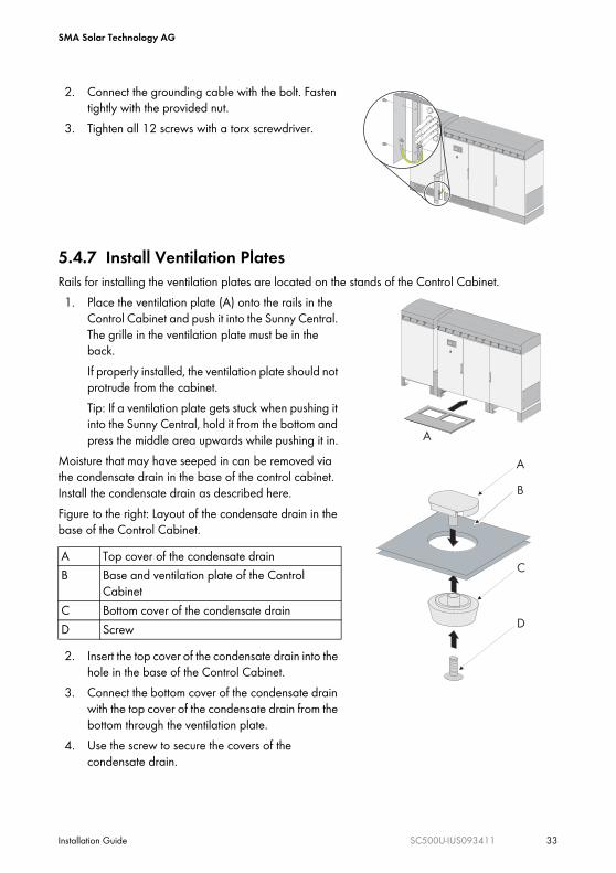
5.4.7 Install Ventilation PlatesRails for installing the ventilation plates are located on the stands of the Control Cabinet.1. Place the ventilation plate (A) onto the rails in the
Control Cabinet and push it into the Sunny Central. The grille in the ventilation plate must be in the back.If properly installed, the ventilation plate should not protrude from the cabinet.Tip: If a ventilation plate gets stuck when pushing it into the Sunny Central, hold it from the bottom and press the middle area upwards while pushing it in.
Moisture that may have seeped in can be removed via the condensate drain in the base of the control cabinet. Install the condensate drain as described here.Figure to the right: Layout of the condensate drain in the base of the Control Cabinet.
2. Insert the top cover of the condensate drain into the hole in the base of the Control Cabinet.
3. Connect the bottom cover of the condensate drain with the top cover of the condensate drain from the bottom through the ventilation plate.
4. Use the screw to secure the covers of the condensate drain.
2. Connect the grounding cable with the bolt. Fasten tightly with the provided nut.
3. Tighten all 12 screws with a torx screwdriver.
A Top cover of the condensate drainB Base and ventilation plate of the Control
CabinetC Bottom cover of the condensate drainD Screw
Stop Start
A
Stop Start
C
D
A
B
SMA Solar Technology AG
34 SC500U-IUS093411 Installation Guide
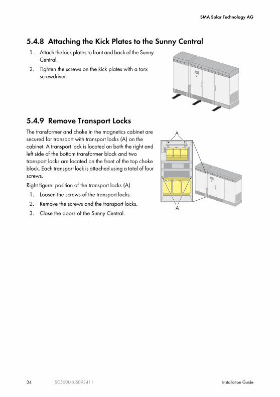
5.4.8 Attaching the Kick Plates to the Sunny Central1. Attach the kick plates to front and back of the Sunny
Central.2. Tighten the screws on the kick plates with a torx
screwdriver.
5.4.9 Remove Transport LocksThe transformer and choke in the magnetics cabinet are secured for transport with transport locks (A) on the cabinet. A transport lock is located on both the right and left side of the bottom transformer block and two transport locks are located on the front of the top choke block. Each transport lock is attached using a total of four screws.Right figure: position of the transport locks (A)1. Loosen the screws of the transport locks.2. Remove the screws and the transport locks.3. Close the doors of the Sunny Central.
Stop Start
A
A
Stop Start
SMA Solar Technology AG
Installation Guide SC500U-IUS093411 35
6 Attaching the ConduitsThis section describes where to insert the cables in the Sunny Central and where to punch the holes for the conduits.
The PV panel cables, the AC cables and the communication cables can be routed into the Sunny Central's interface cabinet from the right or from below. The two options are described below.
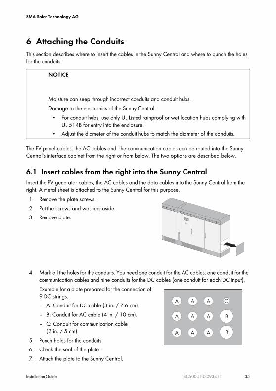
6.1 Insert cables from the right into the Sunny CentralInsert the PV generator cables, the AC cables and the data cables into the Sunny Central from the right. A metal sheet is attached to the Sunny Central for this purpose.1. Remove the plate screws.2. Put the screws and washers aside.3. Remove plate.
4. Mark all the holes for the conduits. You need one conduit for the AC cables, one conduit for the communication cables and nine conduits for the DC cables (one conduit for each DC input).Example for a plate prepared for the connection of 9 DC strings.– A: Conduit for DC cable (3 in. / 7.6 cm).– B: Conduit for AC cable (4 in. / 10 cm).– C: Conduit for communication cable
(2 in. / 5 cm).5. Punch holes for the conduits.6. Check the seal of the plate.7. Attach the plate to the Sunny Central.
NOTICE
Moisture can seep through incorrect conduits and conduit hubs.Damage to the electronics of the Sunny Central.
• For conduit hubs, use only UL Listed rainproof or wet location hubs complying with UL 514B for entry into the enclosure.
• Adjust the diameter of the conduit hubs to match the diameter of the conduits.
Stop Start
C
B
A A
A A A
A A A
A B
SMA Solar Technology AG
36 SC500U-IUS093411 Installation Guide
8. Attach the screws and washers and tighten with a torque of 31 in-lbs (3.5 Nm).9. Insert the conduits into the openings.
10. Attach the conduits with the appropriate hubs.
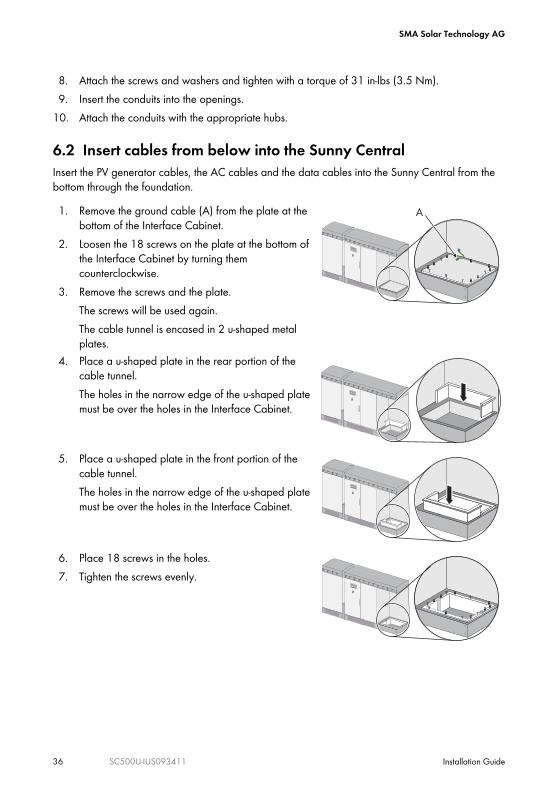
6.2 Insert cables from below into the Sunny CentralInsert the PV generator cables, the AC cables and the data cables into the Sunny Central from the bottom through the foundation.1. Remove the ground cable (A) from the plate at the
bottom of the Interface Cabinet.2. Loosen the 18 screws on the plate at the bottom of
the Interface Cabinet by turning them counterclockwise.
3. Remove the screws and the plate.The screws will be used again.The cable tunnel is encased in 2 u-shaped metal plates.
4. Place a u-shaped plate in the rear portion of the cable tunnel. The holes in the narrow edge of the u-shaped plate must be over the holes in the Interface Cabinet.
5. Place a u-shaped plate in the front portion of the cable tunnel. The holes in the narrow edge of the u-shaped plate must be over the holes in the Interface Cabinet.
6. Place 18 screws in the holes. 7. Tighten the screws evenly.
A
Stop Start
Stop Start
Stop Start
Stop Start
SMA Solar Technology AG
Installation Guide SC500U-IUS093411 37
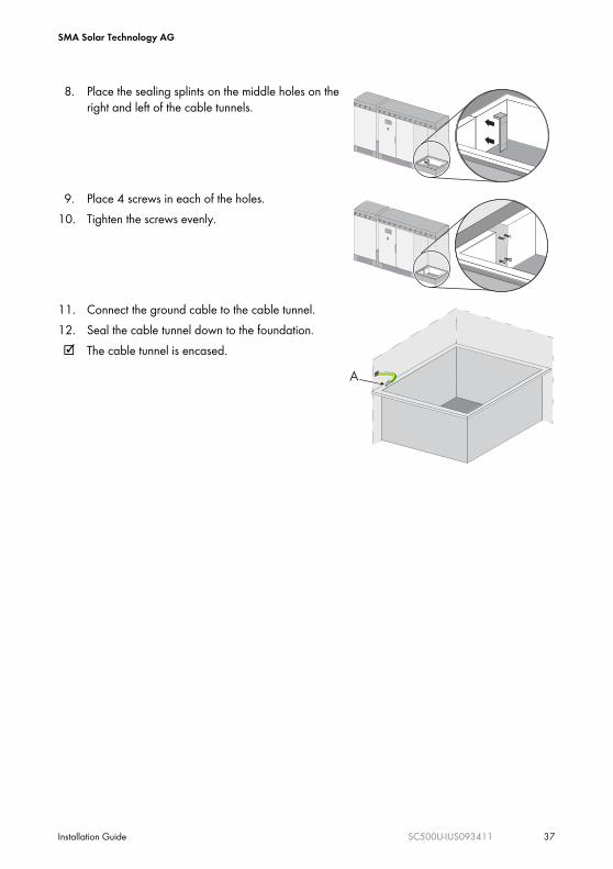
8. Place the sealing splints on the middle holes on the right and left of the cable tunnels.
9. Place 4 screws in each of the holes.10. Tighten the screws evenly.
11. Connect the ground cable to the cable tunnel.12. Seal the cable tunnel down to the foundation.☑ The cable tunnel is encased.
Stop Start
Stop Start
A

SMA Solar Technology AG
38 SC500U-IUS093411 Installation Guide
7 Connecting Optional Communication DevicesThe Sunny Central can be equipped with a Sunny WebBox and/or a Sunny SensorBox. This section explains how the Sunny WebBox and the Sunny Sensor Box in the Sunny Central is connected.
NOTICE
The components in the Sunny Central can be damaged by electrostatic discharge!• When working on the Sunny Central and when handling the components observe all
ESD safety regulations.• Discharge electrostatic charge by touching the grounded Sunny Central enclosure.
NOTICE
Seeping moisture during installation of the Sunny Central.Damage to the electronics of the Sunny Central.
• Do not open the Sunny Central when it is raining or when a high humidity is present (> 95 %).
• For conduit hubs, use only UL Listed rainproof, or wet location hubs complying with UL 514B for entry into the enclosure.

SMA Solar Technology AG
Installation Guide SC500U-IUS093411 39
7.1 Position of the Communication DevicesThe Sunny WebBox is located on the inside of the Interface Cabinet's door.
7.2 Connecting the Sunny SensorBox (optional)This Section describes how to connect the Sunny SensorBox to the Sunny Sensor 485Hub in the Sunny Central.Data cableThe data cable for the connection of the Sunny SensorBox to the Sunny Sensor 485Hub must meet the following requirements:
• The data cable must not be longer than 4,000 ft. (1,200 m)• Use:
– cables with a section of 2 x 2 x AWG 24– shielded twisted pair cables
Position DescriptionA Sunny Sensor 485Hub (see section 7.2 "Connecting the Sunny SensorBox
(optional)" (page 39)). B Sunny WebBox (see section 7.3 "Sunny WebBox (optional)" (page 41)).
Data Cable RecommendationSMA also provides data cables. Please contact your electrician or wholesaler.
BA
SUNNY SENSOR485HUB
SUNNY WEBBOX
USB
CO
MN
ETC
OM
SMAC
OM
ME
MO
RY
REP
OR
TS
YSTE
M
POW
ER
Stop Start
SMA Solar Technology AG
40 SC500U-IUS093411 Installation Guide
7.2.1 Connecting the Data Cable of the Sunny SensorBox
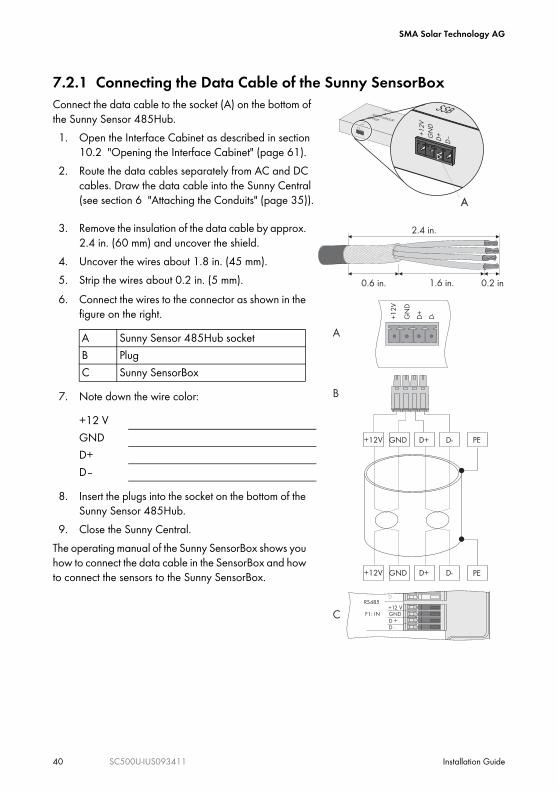
3. Remove the insulation of the data cable by approx. 2.4 in. (60 mm) and uncover the shield.
4. Uncover the wires about 1.8 in. (45 mm).5. Strip the wires about 0.2 in. (5 mm).6. Connect the wires to the connector as shown in the
figure on the right.
7. Note down the wire color:
8. Insert the plugs into the socket on the bottom of the Sunny Sensor 485Hub.
9. Close the Sunny Central.The operating manual of the Sunny SensorBox shows you how to connect the data cable in the SensorBox and how to connect the sensors to the Sunny SensorBox.
Connect the data cable to the socket (A) on the bottom of the Sunny Sensor 485Hub. 1. Open the Interface Cabinet as described in section
10.2 "Opening the Interface Cabinet" (page 61).2. Route the data cables separately from AC and DC
cables. Draw the data cable into the Sunny Central (see section 6 "Attaching the Conduits" (page 35)).
A Sunny Sensor 485Hub socketB PlugC Sunny SensorBox
+12 VGNDD+D–
SUNNY SENSOR485HUB
SSB
Communication
Activity
Activity
Power
Power
+1
2V
GN
DD
+
D–
A
2.4 in.
0.6 in. 1.6 in. 0.2 in
+1
2V
GN
D
D+
D-
D+GND+12V D-
D+GND+12V D-
+12 VGNDD +D -
F1: IN
F2: OUT
RS485
D +D -
PE
PE
C
B
A
SMA Solar Technology AG
Installation Guide SC500U-IUS093411 41
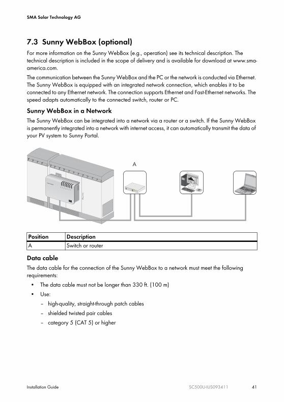
7.3 Sunny WebBox (optional)For more information on the Sunny WebBox (e.g., operation) see its technical description. The technical description is included in the scope of delivery and is available for download at www.sma-america.com.The communication between the Sunny WebBox and the PC or the network is conducted via Ethernet. The Sunny WebBox is equipped with an integrated network connection, which enables it to be connected to any Ethernet network. The connection supports Ethernet and Fast-Ethernet networks. The speed adapts automatically to the connected switch, router or PC.Sunny WebBox in a NetworkThe Sunny WebBox can be integrated into a network via a router or a switch. If the Sunny WebBox is permanently integrated into a network with internet access, it can automatically transmit the data of your PV system to Sunny Portal.
Data cableThe data cable for the connection of the Sunny WebBox to a network must meet the following requirements:
• The data cable must not be longer than 330 ft. (100 m)• Use:
– high-quality, straight-through patch cables– shielded twisted pair cables– category 5 (CAT 5) or higher
Position DescriptionA Switch or router
A
USBC
OMNETC
OMSM
ACOM
MEMORY
REPO
RT
SYST
EM
POW
ER
SUNNY WEBBOX
SMA Solar Technology AG
42 SC500U-IUS093411 Installation Guide
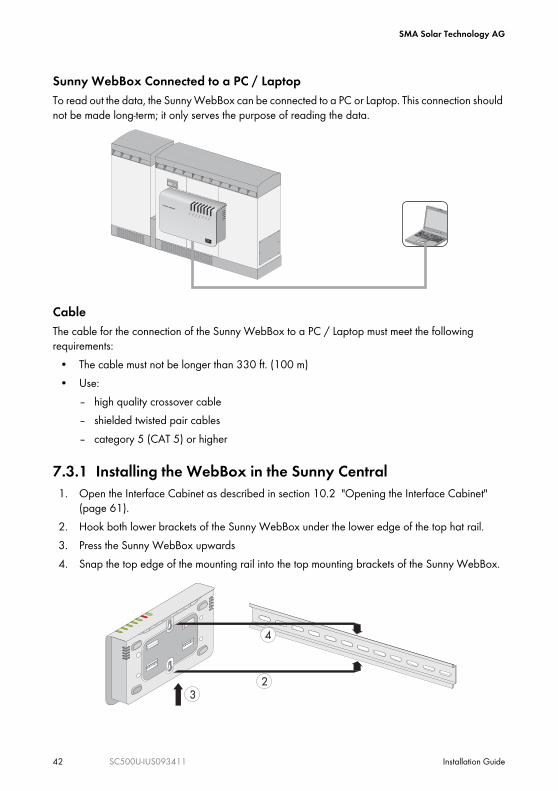
Sunny WebBox Connected to a PC / LaptopTo read out the data, the Sunny WebBox can be connected to a PC or Laptop. This connection should not be made long-term; it only serves the purpose of reading the data.
CableThe cable for the connection of the Sunny WebBox to a PC / Laptop must meet the following requirements:
• The cable must not be longer than 330 ft. (100 m)• Use:
– high quality crossover cable– shielded twisted pair cables– category 5 (CAT 5) or higher
7.3.1 Installing the WebBox in the Sunny Central1. Open the Interface Cabinet as described in section 10.2 "Opening the Interface Cabinet"
(page 61).2. Hook both lower brackets of the Sunny WebBox under the lower edge of the top hat rail.3. Press the Sunny WebBox upwards4. Snap the top edge of the mounting rail into the top mounting brackets of the Sunny WebBox.
USBC
OMNETC
OMSM
ACOM
MEMORY
REPO
RT
SYST
EM
POW
ER
SUNNY WEBBOX
23
4
SMA Solar Technology AG
Installation Guide SC500U-IUS093411 43
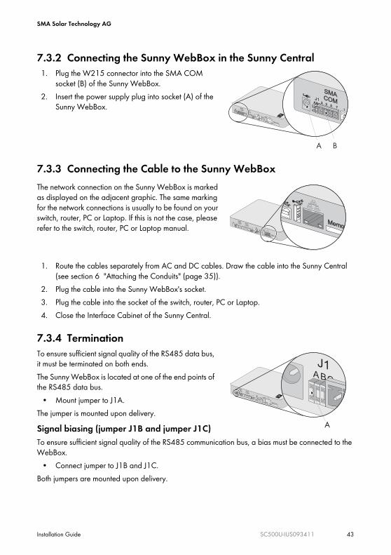
7.3.2 Connecting the Sunny WebBox in the Sunny Central1. Plug the W215 connector into the SMA COM
socket (B) of the Sunny WebBox.2. Insert the power supply plug into socket (A) of the
Sunny WebBox.
7.3.3 Connecting the Cable to the Sunny WebBox
1. Route the cables separately from AC and DC cables. Draw the cable into the Sunny Central (see section 6 "Attaching the Conduits" (page 35)).
2. Plug the cable into the Sunny WebBox's socket.3. Plug the cable into the socket of the switch, router, PC or Laptop.4. Close the Interface Cabinet of the Sunny Central.
7.3.4 TerminationTo ensure sufficient signal quality of the RS485 data bus, it must be terminated on both ends.The Sunny WebBox is located at one of the end points of the RS485 data bus.
• Mount jumper to J1A.The jumper is mounted upon delivery.Signal biasing (jumper J1B and jumper J1C)To ensure sufficient signal quality of the RS485 communication bus, a bias must be connected to the WebBox.
• Connect jumper to J1B and J1C.Both jumpers are mounted upon delivery.
The network connection on the Sunny WebBox is marked as displayed on the adjacent graphic. The same marking for the network connections is usually to be found on your switch, router, PC or Laptop. If this is not the case, please refer to the switch, router, PC or Laptop manual.
A B
A
SMA Solar Technology AG
44 SC500U-IUS093411 Installation Guide
8 Electrical ConnectionThis section describes how the Sunny Central is connected to the grid and to the PV modules, and what precautions must be observed in order to avoid material and personal damages. It provides information on the necessary cable sizes and the magnitude of the torque for the cable connection.
8.1 SafetyDANGER
Normally grounded conductors may be ungrounded and energized when a ground-fault is indicated.Risk of electric shock.
• Test before touching.• Work on the Sunny Central must be carried out by qualified personnel.
NOTICE
Seeping moisture during installation of the Sunny Central.Damage to the electronics of the Sunny Central.
• Do not open the Sunny Central when it is raining or when a high humidity is present (> 95 %).
• For conduit hubs, use only UL Listed rainproof, or wet location hubs complying with UL 514B for entry into the enclosure.

SMA Solar Technology AG
Installation Guide SC500U-IUS093411 45
8.2 Connection AreaThe cables of the PV modules and the public grid are connected in the Interface Cabinet. Sunny Central for the connection of 9 DC strings
Position DescriptionA Grounded DC connection (in figure above DC– connection)B Ungrounded DC connection (in figure above DC+ connection)C AC connectionD Ground connection
Left side Middle Right side Door
Base

SMA Solar Technology AG
46 SC500U-IUS093411 Installation Guide
8.3 Connection OptionsThere are various options for connecting the Sunny Central to the public grid and the PV modules. When placing your order these options will enable you to adapt the Sunny Central connection area to the characteristics of the PV modules and the grid. This section demonstrates the various connection options.
8.3.1 Grid Types
The Sunny Central can be connected to the following grids:• 480 Delta:277 WYE (preset)• 480 Delta
The figure below illustrates the grid types.
8.3.2 DC FusesThe Sunny Central can be delivered with 6, 7, 8 or 9 DC fuses. Every fuse has a separate rail to which 1 or 2 DC strings can be connected.
8.3.3 Grounding the PV modulesDepending on the configuration option, you can connect positive or negative grounded PV modules to the Sunny Central.
DANGER
During operation, high voltages are present in the Sunny Central.Death resulting from burning and electric shock.
• The cofiguration of the Sunny Central for another grid may only be maintained by SMA service personnel. Contact the SMA Serviceline for support (see section 14 "Contact" (page 72)).
480 V
480 V480 V
480 V
480 V 480 V277 V
277 V 277 V
N
A A
C BC B
SMA Solar Technology AG
Installation Guide SC500U-IUS093411 47
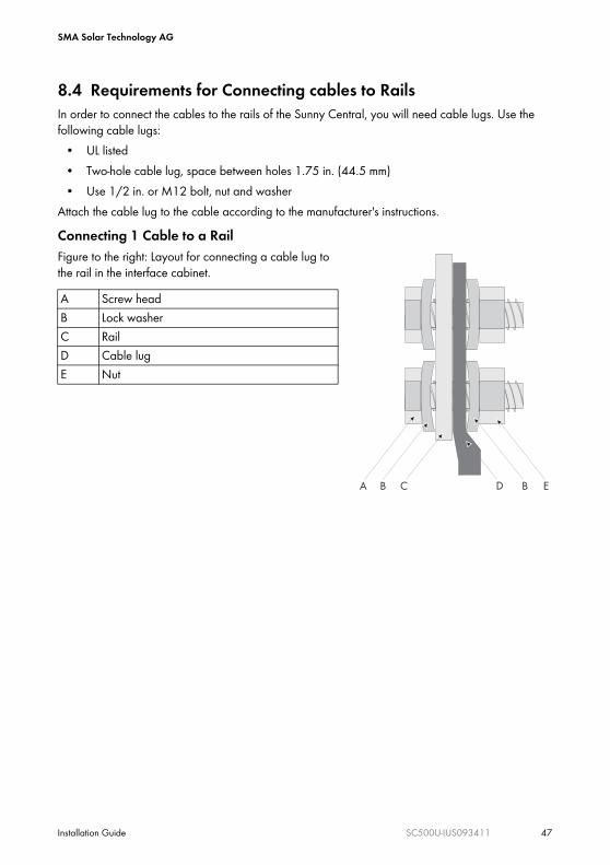
8.4 Requirements for Connecting cables to RailsIn order to connect the cables to the rails of the Sunny Central, you will need cable lugs. Use the following cable lugs:
• UL listed• Two-hole cable lug, space between holes 1.75 in. (44.5 mm)• Use 1/2 in. or M12 bolt, nut and washer
Attach the cable lug to the cable according to the manufacturer's instructions.Connecting 1 Cable to a RailFigure to the right: Layout for connecting a cable lug to the rail in the interface cabinet.A Screw headB Lock washerC RailD Cable lugE Nut
EBDCBA
SMA Solar Technology AG
48 SC500U-IUS093411 Installation Guide
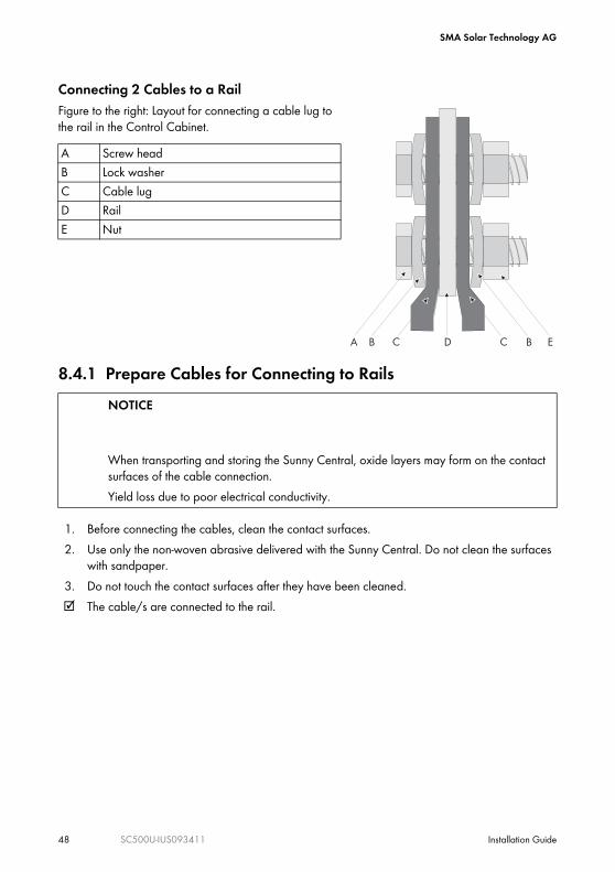
Connecting 2 Cables to a RailFigure to the right: Layout for connecting a cable lug to the rail in the Control Cabinet.
8.4.1 Prepare Cables for Connecting to Rails
1. Before connecting the cables, clean the contact surfaces.2. Use only the non-woven abrasive delivered with the Sunny Central. Do not clean the surfaces
with sandpaper.3. Do not touch the contact surfaces after they have been cleaned.☑ The cable/s are connected to the rail.
A Screw headB Lock washerC Cable lugD RailE Nut
NOTICE
When transporting and storing the Sunny Central, oxide layers may form on the contact surfaces of the cable connection.Yield loss due to poor electrical conductivity.
EBCDCBA

SMA Solar Technology AG
Installation Guide SC500U-IUS093411 49
8.5 Connection of the PV Modules
8.5.1 RequirementsDo not connect the PV modules until the optional communication cables have been connected (see section 7 "Connecting Optional Communication Devices" (page 38)). DC distribution boxes (e.g. Sunny Central String-Monitor) must be installed between the PV modules and the Sunny Central, where the PV module cables are gathered and led to the Sunny Central. The Photovoltaic System Grounding must be installed per the requirements of Sections 690.41 through 690.47 of the National Electrical Code, ANSI/NFPA 70 and is the responsibility of the installer.Technical Data for the Connection of the PV Modules
Torques and Cable Sizes for DC+, DC– and PECopper conductors only - use solid, or stranded copper only.The Sunny Central can be delivered with 6, 7, 8 or 9 DC fuses. Every fuse has a separate rail to which 1 or 2 DC strings can be connected. Below you find the cable sizes and torques for the connection of the strings.
Number of strings 6 (12), 7 (14), 8 (16) or 9 (18)DC input voltage 330 - 600 V DCMax. DC current 1600 A
DC fuses Number of DC Strings
Cable Size Torque max. DC fuse rating
6 6 800 kcmil All 194 °F (90 °C) copper wire, 55 ft-lbs (75 Nm)
tightening torque
450 A12 350 kcmil
7 7 600 kcmil All 194 °F (90 °C) copper wire, 55 ft-lbs (75 Nm)
tightening torque
400 A14 300 kcmil
8 8 500 kcmil All 194 °F (90 °C) copper wire, 55 ft-lbs (75 Nm)
tightening torque
350 A16 4/0 AWG
9 9 400 kcmil All 194 °F (90 °C) copper wire, 55 ft-lbs (75 Nm)
tightening torque
300 A18 4/0 AWG
SMA Solar Technology AG
50 SC500U-IUS093411 Installation Guide
8.5.2 Connecting the PV Modules
1. Open the Sunny Central as described in chapter 10 "Opening the Sunny Central" (page 60).
2. Cover the PV modules.3. Switch off the fuses in the DC distribution boxes (e.g. Sunny Central String-Monitor) and secure
them against reconnection.4. Follow all safety precautions of the module manufacturer.5. Lead the cables into the Sunny Central, as described in Section 6 "Attaching the Conduits"
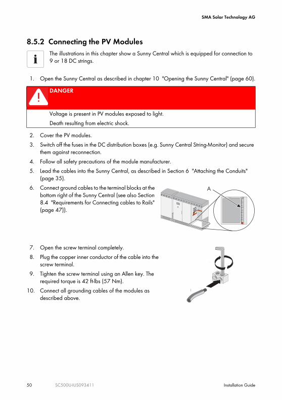
(page 35).6. Connect ground cables to the terminal blocks at the
bottom right of the Sunny Central (see also Section 8.4 "Requirements for Connecting cables to Rails" (page 47)).
7. Open the screw terminal completely.8. Plug the copper inner conductor of the cable into the
screw terminal.9. Tighten the screw terminal using an Allen key. The
required torque is 42 ft-lbs (57 Nm).10. Connect all grounding cables of the modules as
described above.
The illustrations in this chapter show a Sunny Central which is equipped for connection to 9 or 18 DC strings.
DANGER
Voltage is present in PV modules exposed to light.Death resulting from electric shock.
A
Stop Start
4
3
SMA Solar Technology AG
Installation Guide SC500U-IUS093411 51
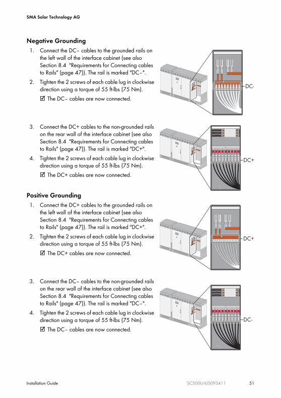
Negative Grounding1. Connect the DC– cables to the grounded rails on
the left wall of the interface cabinet (see also Section 8.4 "Requirements for Connecting cables to Rails" (page 47)). The rail is marked "DC–".
2. Tighten the 2 screws of each cable lug in clockwise direction using a torque of 55 ft-lbs (75 Nm).☑ The DC– cables are now connected.
3. Connect the DC+ cables to the non-grounded rails on the rear wall of the interface cabinet (see also Section 8.4 "Requirements for Connecting cables to Rails" (page 47)). The rail is marked "DC+".
4. Tighten the 2 screws of each cable lug in clockwise direction using a torque of 55 ft-lbs (75 Nm).☑ The DC+ cables are now connected.
Positive Grounding1. Connect the DC+ cables to the grounded rails on
the left wall of the interface cabinet (see also Section 8.4 "Requirements for Connecting cables to Rails" (page 47)). The rail is marked "DC+".
2. Tighten the 2 screws of each cable lug in clockwise direction using a torque of 55 ft-lbs (75 Nm).☑ The DC+ cables are now connected.
3. Connect the DC– cables to the non-grounded rails on the rear wall of the interface cabinet (see also Section 8.4 "Requirements for Connecting cables to Rails" (page 47)). The rail is marked "DC–".
4. Tighten the 2 screws of each cable lug in clockwise direction using a torque of 55 ft-lbs (75 Nm).☑ The DC– cables are now connected.

SMA Solar Technology AG
52 SC500U-IUS093411 Installation Guide
8.6 AC Connection
8.6.1 Requirements
The AC input and AC output circuits are isolated from the enclosure and the system grounding, if required by Section 250 of the National Electrical Code, ANSI/NFPA 70, is the responsibility of the installer.Technical Data for the AC Connection
Connection to the AC Grid
CAUTION
Improper connection to the public grid may cause a fire.Burns from fire.To reduce the risk of fire,
• connect only to a circuit provided with 900 amperes maximum branch-circuit overcurrent protection in accordance with the National Electrical Code, ANSI/NFPA 70.
• do not connect to an AC load center (circuit breaker panel) having multiwire branch circuits connected.
Nominal AC voltage 480 V ACMax. AC current 601.4 A
Number of AC Cables
Cable Size Torque
A, B, C 6 400 kcmil All 194 °F (90 °C) copper wire, 42 ft-lbs (57 Nm) tightening torque
N (only for 480
Delta:277 WYE)
1 or 2 4 AWG – 600 kcmil All 194 °F (90 °C) copper wire, 42 ft-lbs (57 Nm) tightening torque
PE 1 3/0 AWG – 600 kcmil
42 ft-lbs (57 Nm)

SMA Solar Technology AG
Installation Guide SC500U-IUS093411 53
8.6.2 Connecting AC
1. Pay close attention to all safety precaution measures regarding the low voltage grid.2. Switch off the AC disconnect and secure it against accidental switching on.3. Ensure that no voltage is present.4. Open the Sunny Central as described in Section 10 "Opening the Sunny Central" (page 60).5. Lead the cables into the Sunny Central as described in Section 6 "Attaching the Conduits"
(page 35).6. Connect ground cables to the terminal blocks at the
bottom right of the Sunny Central.
7. Open the screw terminal completely.8. Plug the copper inner conductor of the cable into the
screw terminal.9. Tighten the screw terminal using an Allen key. The
required torque is 42 ft-lbs (57 Nm).10. Connect all grounding cables of the modules as
described above.
DANGER
High voltages are present in the live components of the low voltage grid.Death resulting from burning and electric shock.
11. Open the AC terminals completely.12. Connect phase A to the terminal marked "A". Tighten
the screw terminal using an Allen key. The required torque is 42 ft-lbs (57 Nm).
A
Stop Start
4
3
SMA Solar Technology AG
54 SC500U-IUS093411 Installation Guide
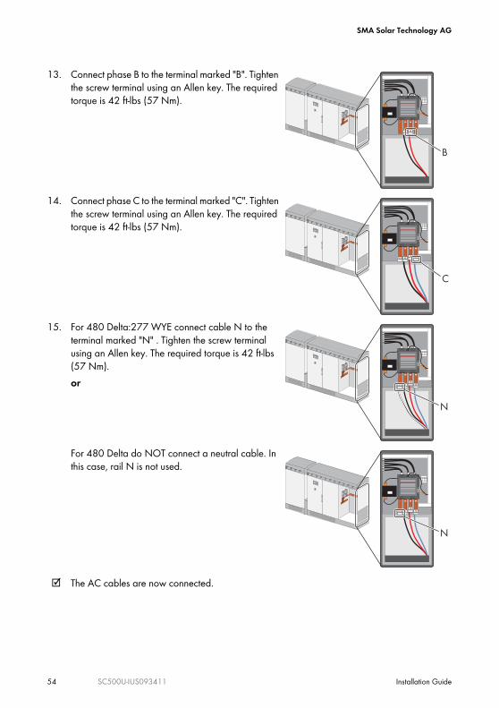
☑ The AC cables are now connected.
13. Connect phase B to the terminal marked "B". Tighten the screw terminal using an Allen key. The required torque is 42 ft-lbs (57 Nm).
14. Connect phase C to the terminal marked "C". Tighten the screw terminal using an Allen key. The required torque is 42 ft-lbs (57 Nm).
15. For 480 Delta:277 WYE connect cable N to the terminal marked "N" . Tighten the screw terminal using an Allen key. The required torque is 42 ft-lbs (57 Nm).or
For 480 Delta do NOT connect a neutral cable. In this case, rail N is not used.
SMA Solar Technology AG
Installation Guide SC500U-IUS093411 55
9 CommissioningThis section explains, step-by-step, how to put the Sunny Central into operation, and how you can determine that the commissioning was successful.
9.1 Visual Inspection of the Sunny Central1. Ensure that all AC and DC voltages are not connected to the inverter.2. Wait 8 minutes for all internal power supplies to discharge.3. Check voltage in order to ensure that all voltages have been removed4. Inspect all large power cables and bus connections throughout the inverter to verify that they
are tight.5. Verify that all PV wires are connected with the proper polarity.6. Verify that all PV wires are tightened to the proper torque specification.7. Verify that the PV ground wires are connected to ground and are isolated from PV+ or PV–.8. Verify that the AC neutral wire is connected to the AC Neutral terminal (only for 480 Delta:277
WYE).9. Verify that the AC phase wires are connected correctly.
10. Verify that all AC phase wires are tightened to the proper torque specification.11. Verify that the AC ground wire is connected correctly.12. Inspect the interior of the Magnetics Cabinet and insure that it is free of any tools, foreign
objects, water, debris or documents.13. Verify that the side panels of the Magnetics Cabinet are closed securely and latched. 14. Leave Control Cabinet and Interface Cabinet open for measurement purposes.
DANGER
Electric shock due to improper startup of the Sunny Central!Death resulting from burning and electric shock.
• All procedures described in this Section shall only be conducted by qualified personnel.
• If problems occur when performing the work described here, contact SMA America.Application to Energy Supply Company
Before you commission the Sunny Central, inform the relevant energy provider. You must submit the following information:
• Date of commissioning.• Technical data of the plant.
SMA Solar Technology AG
56 SC500U-IUS093411 Installation Guide
15. Inspect the interior of the Control Cabinet and Interface Cabinet to insure that they are free of any tools, foreign objects, water, debris or documents.
16. Ensure that the area around the Sunny Central is clear of any tools, foreign objects or debris.17. Check the AC connection for a possible clockwise phase sequence. For this purpose, hold the
terminals of the phase sequence indicator onto the three phases of the AC connection in the Sunny Central. The indicator shows you whether there is clockwise phase sequence.
9.2 Switching the Sunny Central OnDANGER
During operation, high voltages are present in the Sunny Central.Death resulting from electric shock.
• Do not operate the Sunny Central with doors open.
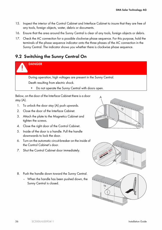
Below, on the door of the Interface Cabinet there is a door stay (A).1. To unlock the door stay (A) push upwards.2. Close the door of the Interface Cabinet. 3. Attach the plate to the Magnetics Cabinet and
tighten the screws.4. Close the right door of the Control Cabinet.5. Inside of the door is a handle. Pull the handle
downwards to lock the door.6. Turn on the automatic circuit-breaker on the inside of
the Control Cabinet’s door.7. Shut the Control Cabinet door immediately.
8. Push the handle down toward the Sunny Central.– When the handle has been pushed down, the
Sunny Central is closed.
A
Stop Start
Stop Start
SMA Solar Technology AG
Installation Guide SC500U-IUS093411 57
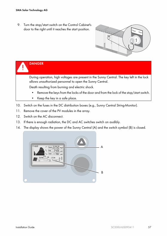
10. Switch on the fuses in the DC distribution boxes (e.g., Sunny Central String-Monitor).11. Remove the cover of the PV modules in the array.12. Switch on the AC disconnect.13. If there is enough radiation, the DC and AC switches switch on audibly. 14. The display shows the power of the Sunny Central (A) and the switch symbol (B) is closed.
9. Turn the stop/start switch on the Control Cabinet's door to the right until it reaches the start position.
DANGER
During operation, high voltages are present in the Sunny Central. The key left in the lock allows unauthorized personnel to open the Sunny Central. Death resulting from burning and electric shock.
• Remove the keys from the locks of the door and from the lock of the stop/start switch. • Keep the key in a safe place.
Stop Start
A
B

SMA Solar Technology AG
58 SC500U-IUS093411 Installation Guide
9.3 Check the VentilationIn operation the Sunny Central is cooled by fans in case the temperature exceeds a defined threshold.
Position DescriptionA In the Magnetics Cabinet, the air is sucked up from below in the front and expelled
at the top in the back and front of the Sunny Central.B In the Control Cabinet, the air is sucked in from the top front and expelled at the
bottom in the back.
A B
SMA Solar Technology AG
Installation Guide SC500U-IUS093411 59
Check the ventilation air flow using a sheet of paper. 1. Hold the piece of paper in front of the air shafts. 2. Check to see whether the sheet is blown away from or sucked toward the inverter.3. Compare the air circulation with what is described in this section.
Result 1The Sunny Central sucks in air and blows it out as described in this section. Commissioning has been successfully completed.Result 2The Sunny Central does not suck air in, nor does it blow it out as described in this section.– Shut down the Sunny Central.– Contact SMA America (see Section 14 "Contact" (page 72)).Result 3The Sunny Central does not suck air in nor does it blow it out, at all.– Check to see whether the Sunny Central is in operation. – If the Sunny Central is in operation, shut it down.– Contact SMA America (see section 14 "Contact" (page 72)).
SMA Solar Technology AG
60 SC500U-IUS093411 Installation Guide
10 Opening the Sunny Central
10.1 Opening the Control Cabinet
DANGER
Electric shock due to improper opening of the Sunny Central!Death resulting from burning and electric shock.
• All procedures described in this Section shall only be conducted by qualified personnel.
• Observe the sequence described here when opening the Sunny Central.• If problems occur when performing the work described here, contact SMA America.
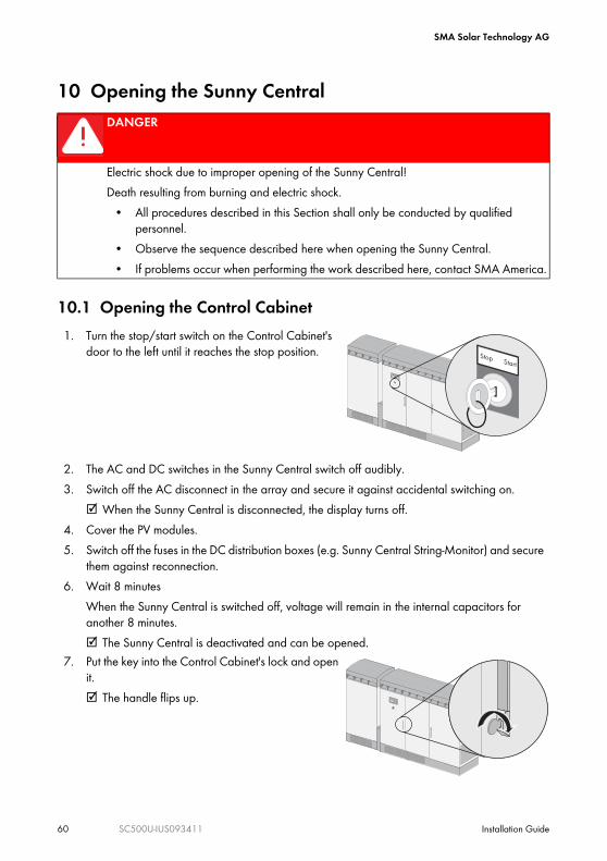
1. Turn the stop/start switch on the Control Cabinet's door to the left until it reaches the stop position.
2. The AC and DC switches in the Sunny Central switch off audibly. 3. Switch off the AC disconnect in the array and secure it against accidental switching on.
☑ When the Sunny Central is disconnected, the display turns off.4. Cover the PV modules.5. Switch off the fuses in the DC distribution boxes (e.g. Sunny Central String-Monitor) and secure
them against reconnection.6. Wait 8 minutes
When the Sunny Central is switched off, voltage will remain in the internal capacitors for another 8 minutes. ☑ The Sunny Central is deactivated and can be opened.
7. Put the key into the Control Cabinet's lock and open it.☑ The handle flips up.
Stop Start
Stop Start
SMA Solar Technology AG
Installation Guide SC500U-IUS093411 61
10.2 Opening the Interface Cabinet12. Switch off the Sunny Central as described in section 10.1 "Opening the Control Cabinet"
(page 60).
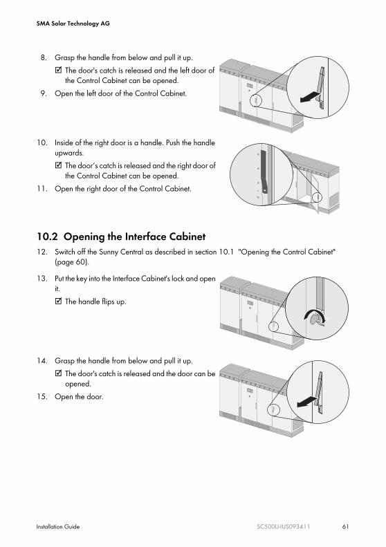
8. Grasp the handle from below and pull it up.☑ The door's catch is released and the left door of
the Control Cabinet can be opened.9. Open the left door of the Control Cabinet.
10. Inside of the right door is a handle. Push the handle upwards.☑ The door‘s catch is released and the right door of
the Control Cabinet can be opened.11. Open the right door of the Control Cabinet.
13. Put the key into the Interface Cabinet's lock and open it.☑ The handle flips up.
14. Grasp the handle from below and pull it up.☑ The door's catch is released and the door can be
opened.15. Open the door.
Stop Start
Stop Start
Stop Start
SMA Solar Technology AG
62 SC500U-IUS093411 Installation Guide
16. Verify the absence of voltage with respect to ground at the AC clamp with an appropriate meter.☑ If there is a voltage present, the installation must be checked.
17. Verify the absence of voltage with respect to ground at the DC clamp with an appropriate meter.☑ If there is a voltage present, the installation must be checked.
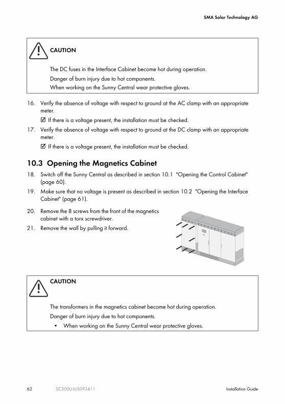
10.3 Opening the Magnetics Cabinet18. Switch off the Sunny Central as described in section 10.1 "Opening the Control Cabinet"
(page 60).19. Make sure that no voltage is present as described in section 10.2 "Opening the Interface
Cabinet" (page 61).
CAUTION
The DC fuses in the Interface Cabinet become hot during operation.Danger of burn injury due to hot components.When working on the Sunny Central wear protective gloves.
20. Remove the 8 screws from the front of the magnetics cabinet with a torx screwdriver.
21. Remove the wall by pulling it forward.
CAUTION
The transformers in the magnetics cabinet become hot during operation.Danger of burn injury due to hot components.
• When working on the Sunny Central wear protective gloves.
Stop Start

SMA Solar Technology AG
Installation Guide SC500U-IUS093411 63
11 MaintenanceThe Sunny Central inverter must be maintained at regular intervals. Maintenance includes cleaning of cabinet interior, if necessary.The maintenance interval depends on the location and the ambient conditions.
11.1 Sunny Central Maintenance Work
* The maintenance interval may need to be shortened, depending on the location or ambient conditions.
11.2 Replace DC fuse1. Open the Interface Cabinet as described in section
10.2 "Opening the Interface Cabinet" (page 61).The DC fuses are fastened with 2 screws each.
2. Remove the 2 screws of each DC fuse.3. Remove the DC fuses.
4. Mount fuses vertically (spacer).5. Attach the 2 screws of each DC fuse.6. Tighten afterwards. Use the torque of 44 ft-lbs
(60 Nm).7. Close the Interface Cabinet.
Maintenance work Maintenance interval (recommended)
Check the screens at the air inlets and outlets and clean them if necessary. 6 months *Check the fans. 6 months *Check the air filters of the ventilation plate. 6 months *
L+
L+
SMA Solar Technology AG
64 SC500U-IUS093411 Installation Guide
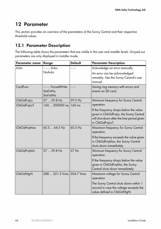
12 ParameterThis section provides an overview of the parameters of the Sunny Central and their respective threshold values.
12.1 Parameter DescriptionThe following table shows the parameters that are visible in the user and installer levels. Grayed out parameters are only displayed in installer mode. Parameter name Range Default Parameter DescriptionAckn –––, Ackn,
NoAckn––– Ackowledge an error manually
An error can be acknowledged remotely. See the Sunny Central's user manual.
CardFunc –––, ForcedWrite, StoEvtHis, StoFailHis
––– Saving ring memory with errors and events on SD card.
ChkGdFrqLo 57 ... 59.8 Hz 59.3 Hz Minimum frequency for Sunny Central operation.If the frequency drops below the value given in ChkGdFrqLo, the Sunny Central will shut down after the time period given in ChkGdFrqLoT.
ChkGdFrqLoT 160 ... 300000 ms 160 ms
ChkGdFrqMax 60.5 ... 64.5 Hz 60.5 Hz Maximum frequency for Sunny Central operation.If the frequency exceeds the value given in ChkGdFrqMax, the Sunny Central shuts down immediately.
ChkGdFrqMin 57 ... 59.8 Hz 57 Hz Minimum frequency for Sunny Central operation.If the frequency drops below the value given in ChkGdFrqMin, the Sunny Central shuts down immediately.
ChkGdVtgHi 288 ... 321.3 Vrms 304.7 Vrms Maximum voltage for Sunny Central operation.The Sunny Central shuts down within 1 second in case the voltage exceeds the value defined in ChkGdVtgHi.
SMA Solar Technology AG
Installation Guide SC500U-IUS093411 65
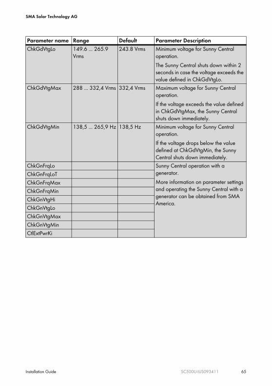
ChkGdVtgLo 149.6 ... 265.9 Vrms
243.8 Vrms Minimum voltage for Sunny Central operation.The Sunny Central shuts down within 2 seconds in case the voltage exceeds the value defined in ChkGdVtgLo.
ChkGdVtgMax 288 ... 332,4 Vrms 332,4 Vrms Maximum voltage for Sunny Central operation.If the voltage exceeds the value defined in ChkGdVtgMax, the Sunny Central shuts down immediately.
ChkGdVtgMin 138,5 ... 265,9 Hz 138,5 Hz Minimum voltage for Sunny Central operation.If the voltage drops below the value defined at ChkGdVtgMin, the Sunny Central shuts down immediately.
ChkGnFrqLo Sunny Central operation with a generator.More information on parameter settings and operating the Sunny Central with a generator can be obtained from SMA America.
ChkGnFrqLoTChkGnFrqMaxChkGnFrqMinChkGnVtgHiChkGnVtgLoChkGnVtgMaxChkGnVtgMinCtlExtPwrKi
Parameter name Range Default Parameter Description

SMA Solar Technology AG
66 SC500U-IUS093411 Installation Guide
CntRs –––, FanHsCnt, FanTrf1Cnt, FanTrf2Cnt, FanCab1Cnt, FanCab2Cnt, GDCtcCut, PvCtcCnt
––– Resetting the hours of operation.Individual meters can be reset (for example after having mounted a new fan).FanHsCnt: Deletes the total running time of the heatsink fan.FanTrf1Cnt: Deletes the total running time of the transformer fan 1.FanTrf2Cnt: Deletes the total running time of the transformer fan 2.FanCab1Cnt: Deletes the total running time of the interior fan 1.FanCab2Cnt: Deletes the total running time of the interior fan 2. PvCtcCnt: The Sunny Central's DC contactor total number of switching operation
Dt yyyymmdd Current Date.Here you can set the current date.
Ofs_E-Total 0 ... 214748364 kWh
0 kWh The Sunny Central's total energy yield.The change of the Ofs_E-Total parameter may be necessary when you exchange your Sunny Central and want to use the data from the old device.
Ofs_FanCab1Cnt 0 ... 2147483 h 0 h Total operating time of fan 1 in the Control Cabinet.The change of the Ofs_FanCab1Cnt parameter may be necessary if you exchange your Sunny Central and want to use the data from the old device.
Ofs_FanCab2Cnt 0 ... 2147483 h 0 h Total operating time of fan 2 in the Control Cabinet.The change of the Ofs_FanCab2Cnt parameter may be necessary if you exchange your Sunny Central and want to use the data from the old device.
Parameter name Range Default Parameter Description

SMA Solar Technology AG
Installation Guide SC500U-IUS093411 67
Ofs_FanHsCnt 0 ... 2147483 h 0 h Total operating time of the heat sink fan in the Control Cabinet.The change of the Ofs_FanHsCnt parameter may be necessary if you exchange your Sunny Central and want to use the data from the old device.
Ofs_FanTrf1Cnt 0 ... 2147483 h 0 h Total operating time of transformer fan 1.The change of the Ofs_FanTrf1Cnt parameter may be necessary if you exchange your Sunny Central and want to use the data from the old device.
Ofs_GdCtcCnt The Sunny Central's grid contactor total number of switching operation.The change of the Ofs_GdCtcCnt parameter may be necessary when you exchange the main circuit board of your Sunny Central and want to use the data from the old one.
Ofs_h_On 0 ... 2147483 h 0 h The Sunny Central's total number of hours of operation.The change of the Ofs_h_On parameter may be necessary when you exchange your Sunny Central and want to use the data from the old device.
Ofs_h_Total 0 ... 2147483 h 0 h Total number of operational hours with grid feeding.The change of the Ofs_h_Total parameter may be necessary when you exchange your Sunny Central and want to use the data from the old device.
Ofs_PVCtcCnt The Sunny Central's DC contactor total number of switching operation.The change of the Ofs_PvCtcCnt parameter may be necessary when you exchange the main circuit board of your Sunny Central and want to use the data from the old one.
ParaLod –––, Set1, Set2, Factory
––– Loading parameters from SD card.Factory: Factory parameter settings are being loaded.
Parameter name Range Default Parameter Description

SMA Solar Technology AG
68 SC500U-IUS093411 Installation Guide
12.2 Changing ParametersThe changing of the parameters itself is described in the Sunny Central’s User Manual.
ParaSto –––, Set1, Set2 ––– Saving parameter on SD card.Plimit 0 ... 1000 kW 500 kW Upper limit for AC output power
This parameter cannot be changed.Pmax 0 ... 500 kW 500 kW Output limit of the Sunny Central
Changing the parameter can reduce the output power of the Sunny Central.
PVPwrMinTr 0 ... 1200 kW 10 kW MPP trackingIf the output exceeds the value PVPwrMinTr, the Sunny Central will wait for a period of time set in PVPwrMinTrT before it begins to seek the Maximum Power Point.
PVPwrMinTrT 1 ... 1800 s 600 s
PVStrT 1 ... 1800 s 90 s Initial voltage of the Sunny Central.If the voltage increases over the value set at PVVtgStr, the Sunny Central will start after waiting for a period of time set at PVStrT.
PVVtgStr 0 ... 1200 V 400 V
Serial Number Serial number of the Sunny Central. This parameter cannot be changed.
SpntGnMod Sunny Central operation with a generator.These parameters are for operation with a generator. Contact SMA America if you have questions regarding the operation of the Sunny Central with a generator.
SpntGnPwrMin
SpntRemEna ---, Off, On On Shutting down the Sunny Central.With these parameters the Sunny Central can be shut down remotely.
Tm hhmmss Current Time.Here you can set the current time.
Parameter name Range Default Parameter Description

SMA Solar Technology AG
Installation Guide SC500U-IUS093411 69
13 Technical DataIn this section you will find the technical data for the Sunny Central's operation, the norms to which it conforms and the required cables and torques.PV Generator Connection Data
Grid Connection Data
General Data
DC input voltage 300 ... 600 V DCInput voltage, MPP range 330 ... 600 V DCDC starting voltage 400 V DC (adjustable)Max. input current 1,600 ADC voltage ripple (peak to peak) < 3 %
Nominal output power (at 77 °F (25 °C)) 500 kWNominal output power (at 113 °F (45 °C)) 500 kWOutput power at 300 V DC 460 kWNominal AC voltageOperating range
480 V AC422 ... 528 V AC
AC nominal frequencyOperating range
60 Hz59.3 ... 60.5 Hz
Max. AC current 601.4 A AC (at 480 V AC)
Inverter technology True sine wave, current source, high frequency PWM with galvanic insulation
Max. operating altitude 13,000 ft. (4,000 m) above sea levelPower Reduction:The Sunny Central can function without power reduction up to 3,300 feet (1,000 m) above sea level. At higher altitudes the power is reduced by 5 % per 3,300 ft (1,000 m).
Ambient temperatures -13 °F ...113 °F (-25 °C ... 45 °C) (without power reduction)-13 °F ... 122 °F (-25 °C ... 50 °C) (with power reduction)Output power at 122 °F (50 °C) = approx. 347 kW
Cooling Temperature-controlled fans for cooling. Easily removable filters, easily accessible.
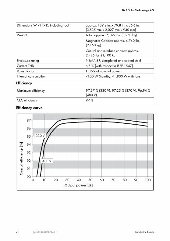
SMA Solar Technology AG
70 SC500U-IUS093411 Installation Guide
Efficiency
Efficiency curve
Dimensions W x H x D, including roof approx. 139.2 in. x 79.8 in. x 36.6 in. (3,535 mm x 2,027 mm x 930 mm)
Weight Total: approx. 7,165 lbs. (3,250 kg)Magnetics Cabinet: approx. 4,740 lbs. (2,150 kg)Control and interface cabinet: approx. 2,425 lbs. (1,100 kg)
Enclosure rating NEMA 3R, zinc-plated and coated steelCurrent THD < 5 % (with respect to IEEE 1547)Power factor > 0.99 at nominal powerInternal consumption <100 W Standby, <1,800 W with fans
Maximum efficiency 97.37 % (330 V), 97.25 % (370 V), 96.94 % (480 V)
CEC efficiency 97 %
090
10 20 30 40 50 60 8070 10090
91
92
93
94
95
96
97
330 V
480 V
Over
all ef
ficien
cy [%
]
Output power [%]
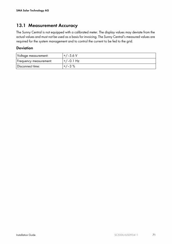
SMA Solar Technology AG
Installation Guide SC500U-IUS093411 71
13.1 Measurement AccuracyThe Sunny Central is not equipped with a calibrated meter. The display values may deviate from the actual values and must not be used as a basis for invoicing. The Sunny Central’s measured values are required for the system management and to control the current to be fed to the grid.DeviationVoltage measurement: +/–5.6 VFrequency measurement: +/–0.1 HzDisconnect time: +/–3 %
SMA Solar Technology AG
72 SC500U-IUS093411 Installation Guide
14 ContactIf you have technical problems concerning our products, contact your installer or the SMA Serviceline. We require the following information in order to provide you with the necessary assistance:
• Inverter type• Type and number of modules connected• Communication method• Serial number of the Sunny Central• Failure or warning number of the Sunny Central• Display of the Sunny Central
SMA America, Incorporated4031 Alvis CourtRocklin, CA 95677, USATel. +1 916 625 0870Fax +1 916 625 [email protected]
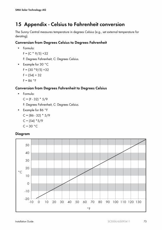
SMA Solar Technology AG
Installation Guide SC500U-IUS093411 73
15 Appendix - Celsius to Fahrenheit conversionThe Sunny Central measures temperature in degrees Celsius (e.g., set external temperature for derating).Conversion from Degrees Celsius to Degrees Fahrenheit
• Formula:F = (C * 9/5) +32F: Degrees Fahrenheit, C: Degrees Celsius.
• Example for 30 °CF = (30 *9/5) +32F = (54) + 32F = 86 °F
Conversion from Degrees Fahrenheit to Degrees Celsius• Formula:
C = (F - 32) * 5/9 F: Degrees Fahrenheit, C: Degrees Celsius.
• Example for 86 °FC = (86 - 32) * 5/9C = (54) *5/9C = 30 °C
Diagram
-10-20
-10
0
10
20
30
40
50
0 10 20 30 5040 60 70 9080 100 110 120 130
°C
°F
SMA Solar Technology AG
74 SC500U-IUS093411 Installation Guide


SMA America, Incorporated


![[2013修正] Kit 4 1660002JEDU D E - Bio-Rad Laboratories...Hind IIIで切断したラムダファージDNA(DNAマーカー) [0.2g/l]、100l 1バイアル 制限酵素Hind III-[500U]、40l](https://img.dokumen.tips/doc/110x75/6088dfa0d38035406b112fba/2013-kit-4-1660002jedu-d-e-bio-rad-laboratories-hind-iiifffffdnaidnafffi.jpg)