Embed Size (px)
Citation preview
Sun Microsystems, Inc.www.sun.com
Submit comments about this document at: http://www.sun.com/hwdocs/feedback
Sun Fire™ T2000 ServerService Manual
Part No. 819-2548-14July 2007, Revision A
Copyright 2007 Sun Microsystems, Inc., 4150 Network Circle, Santa Clara, California 95054, U.S.A. All rights reserved.
Fujitsu Limited provided technical input and review on portions of this material.
Sun Microsystems, Inc. and Fujitsu Limited each own or control intellectual property rights relating to products and technology described inthis document, and such products, technology and this document are protected by copyright laws, patents and other intellectual property lawsand international treaties. The intellectual property rights of Sun Microsystems, Inc. and Fujitsu Limited in such products, technology and thisdocument include, without limitation, one or more of the United States patents listed at http://www.sun.com/patents and one or moreadditional patents or patent applications in the United States or other countries.
This document and the product and technology to which it pertains are distributed under licenses restricting their use, copying, distribution,and decompilation. No part of such product or technology, or of this document, may be reproduced in any form by any means without priorwritten authorization of Fujitsu Limited and Sun Microsystems, Inc., and their applicable licensors, if any. The furnishing of this document toyou does not give you any rights or licenses, express or implied, with respect to the product or technology to which it pertains, and thisdocument does not contain or represent any commitment of any kind on the part of Fujitsu Limited or Sun Microsystems, Inc., or any affiliate ofeither of them.
This document and the product and technology described in this document may incorporate third-party intellectual property copyrighted byand/or licensed from suppliers to Fujitsu Limited and/or Sun Microsystems, Inc., including software and font technology.
Per the terms of the GPL or LGPL, a copy of the source code governed by the GPL or LGPL, as applicable, is available upon request by the EndUser. Please contact Fujitsu Limited or Sun Microsystems, Inc.
This distribution may include materials developed by third parties.
Parts of the product may be derived from Berkeley BSD systems, licensed from the University of California. UNIX is a registered trademarkin the U.S. and in other countries, exclusively licensed through X/Open Company, Ltd.
Sun, Sun Microsystems, the Sun logo, Java, Netra, Solaris, Sun StorEdge, SPARC Enterprise, docs.sun.com, OpenBoot, SunVTS, Sun Fire,SunSolve, CoolThreads, J2EE, and Sun are trademarks or registered trademarks of Sun Microsystems, Inc. in the U.S. and other countries.
Fujitsu and the Fujitsu logo are registered trademarks of Fujitsu Limited.
All SPARC trademarks are used under license and are registered trademarks of SPARC International, Inc. in the U.S. and other countries.Products bearing SPARC trademarks are based upon architecture developed by Sun Microsystems, Inc.
SPARC64 is a trademark of SPARC International, Inc., used under license by Fujitsu Microelectronics, Inc. and Fujitsu Limited.
The OPEN LOOK and Sun™ Graphical User Interface was developed by Sun Microsystems, Inc. for its users and licensees. Sun acknowledgesthe pioneering efforts of Xerox in researching and developing the concept of visual or graphical user interfaces for the computer industry. Sunholds a non-exclusive license from Xerox to the Xerox Graphical User Interface, which license also covers Sun’s licensees who implement OPENLOOK GUIs and otherwise comply with Sun’s written license agreements.
United States Government Rights - Commercial use. U.S. Government users are subject to the standard government user license agreements ofSun Microsystems, Inc. and Fujitsu Limited and the applicable provisions of the FAR and its supplements.
Disclaimer: The only warranties granted by Fujitsu Limited, Sun Microsystems, Inc. or any affiliate of either of them in connection with thisdocument or any product or technology described herein are those expressly set forth in the license agreement pursuant to which the productor technology is provided. EXCEPT AS EXPRESSLY SET FORTH IN SUCH AGREEMENT, FUJITSU LIMITED, SUN MICROSYSTEMS, INC.AND THEIR AFFILIATES MAKE NO REPRESENTATIONS OR WARRANTIES OF ANY KIND (EXPRESS OR IMPLIED) REGARDING SUCHPRODUCT OR TECHNOLOGY OR THIS DOCUMENT, WHICH ARE ALL PROVIDED AS IS, AND ALL EXPRESS OR IMPLIEDCONDITIONS, REPRESENTATIONS AND WARRANTIES, INCLUDING WITHOUT LIMITATION ANY IMPLIED WARRANTY OFMERCHANTABILITY, FITNESS FOR A PARTICULAR PURPOSE OR NON-INFRINGEMENT, ARE DISCLAIMED, EXCEPT TO THEEXTENT THAT SUCH DISCLAIMERS ARE HELD TO BE LEGALLY INVALID. Unless otherwise expressly set forth in such agreement, to theextent allowed by applicable law, in no event shall Fujitsu Limited, Sun Microsystems, Inc. or any of their affiliates have any liability to anythird party under any legal theory for any loss of revenues or profits, loss of use or data, or business interruptions, or for any indirect, special,incidental or consequential damages, even if advised of the possibility of such damages.
DOCUMENTATION IS PROVIDED “AS IS” AND ALL EXPRESS OR IMPLIED CONDITIONS, REPRESENTATIONS AND WARRANTIES,INCLUDING ANY IMPLIED WARRANTY OF MERCHANTABILITY, FITNESS FOR A PARTICULAR PURPOSE OR NON-INFRINGEMENT,ARE DISCLAIMED, EXCEPT TO THE EXTENT THAT SUCH DISCLAIMERS ARE HELD TO BE LEGALLY INVALID.
Copyright 2007 Sun Microsystems, Inc., 4150 Network Circle, Santa Clara, California 95054, Etats-Unis. Tous droits réservés.
Entrée et revue tecnical fournies par Fujitsu Limited sur des parties de ce matériel.
Sun Microsystems, Inc. et Fujitsu Limited détiennent et contrôlent toutes deux des droits de propriété intellectuelle relatifs aux produits ettechnologies décrits dans ce document. De même, ces produits, technologies et ce document sont protégés par des lois sur le copyright, desbrevets, d’autres lois sur la propriété intellectuelle et des traités internationaux. Les droits de propriété intellectuelle de Sun Microsystems, Inc.et Fujitsu Limited concernant ces produits, ces technologies et ce document comprennent, sans que cette liste soit exhaustive, un ou plusieursdes brevets déposés aux États-Unis et indiqués à l’adresse http://www.sun.com/patents de même qu’un ou plusieurs brevets ou applicationsbrevetées supplémentaires aux États-Unis et dans d’autres pays.
Ce document, le produit et les technologies afférents sont exclusivement distribués avec des licences qui en restreignent l’utilisation, la copie,la distribution et la décompilation. Aucune partie de ce produit, de ces technologies ou de ce document ne peut être reproduite sous quelqueforme que ce soit, par quelque moyen que ce soit, sans l’autorisation écrite préalable de Fujitsu Limited et de Sun Microsystems, Inc., et de leurséventuels bailleurs de licence. Ce document, bien qu’il vous ait été fourni, ne vous confère aucun droit et aucune licence, expresses ou tacites,concernant le produit ou la technologie auxquels il se rapporte. Par ailleurs, il ne contient ni ne représente aucun engagement, de quelque typeque ce soit, de la part de Fujitsu Limited ou de Sun Microsystems, Inc., ou des sociétés affiliées.
Ce document, et le produit et les technologies qu’il décrit, peuvent inclure des droits de propriété intellectuelle de parties tierces protégés parcopyright et/ou cédés sous licence par des fournisseurs à Fujitsu Limited et/ou Sun Microsystems, Inc., y compris des logiciels et destechnologies relatives aux polices de caractères.
Par limites du GPL ou du LGPL, une copie du code source régi par le GPL ou LGPL, comme applicable, est sur demande vers la fin utilsateurdisponible; veuillez contacter Fujitsu Limted ou Sun Microsystems, Inc.
Cette distribution peut comprendre des composants développés par des tierces parties.
Des parties de ce produit pourront être dérivées des systèmes Berkeley BSD licenciés par l’Université de Californie. UNIX est une marquedéposée aux Etats-Unis et dans d’autres pays et licenciée exclusivement par X/Open Company, Ltd.
Sun, Sun Microsystems, le logo Sun, Java, Netra, Solaris, Sun StorEdge, SPARC Enterprise, docs.sun.com, OpenBoot, SunVTS, Sun Fire,SunSolve, CoolThreads, J2EE, et Sun sont des marques de fabrique ou des marques déposées de Sun Microsystems, Inc. aux Etats-Unis et dansd’autres pays.
Fujitsu et le logo Fujitsu sont des marques déposées de Fujitsu Limited.
Toutes les marques SPARC sont utilisées sous licence et sont des marques de fabrique ou des marques déposées de SPARC International, Inc.aux Etats-Unis et dans d’autres pays. Les produits portant les marques SPARC sont basés sur une architecture développée par SunMicrosystems, Inc.
SPARC64 est une marques déposée de SPARC International, Inc., utilisée sous le permis par Fujitsu Microelectronics, Inc. et Fujitsu Limited.
L’interface d’utilisation graphique OPEN LOOK et Sun™ a été développée par Sun Microsystems, Inc. pour ses utilisateurs et licenciés. Sunreconnaît les efforts de pionniers de Xerox pour la recherche et le développement du concept des interfaces d’utilisation visuelle ou graphiquepour l’industrie de l’informatique. Sun détient une license non exclusive de Xerox sur l’interface d’utilisation graphique Xerox, cette licencecouvrant également les licenciés de Sun qui mettent en place l’interface d’utilisation graphique OPEN LOOK et qui, en outre, se conformentaux licences écrites de Sun.
Droits du gouvernement américain - logiciel commercial. Les utilisateurs du gouvernement américain sont soumis aux contrats de licencestandard de Sun Microsystems, Inc. et de Fujitsu Limited ainsi qu’aux clauses applicables stipulées dans le FAR et ses suppléments.
Avis de non-responsabilité: les seules garanties octroyées par Fujitsu Limited, Sun Microsystems, Inc. ou toute société affiliée de l’une ou l’autreentité en rapport avec ce document ou tout produit ou toute technologie décrit(e) dans les présentes correspondent aux garanties expressémentstipulées dans le contrat de licence régissant le produit ou la technologie fourni(e). SAUF MENTION CONTRAIRE EXPRESSÉMENTSTIPULÉE DANS CE CONTRAT, FUJITSU LIMITED, SUN MICROSYSTEMS, INC. ET LES SOCIÉTÉS AFFILIÉES REJETTENT TOUTEREPRÉSENTATION OU TOUTE GARANTIE, QUELLE QU’EN SOIT LA NATURE (EXPRESSE OU IMPLICITE) CONCERNANT CEPRODUIT, CETTE TECHNOLOGIE OU CE DOCUMENT, LESQUELS SONT FOURNIS EN L’ÉTAT. EN OUTRE, TOUTES LES CONDITIONS,REPRÉSENTATIONS ET GARANTIES EXPRESSES OU TACITES, Y COMPRIS NOTAMMENT TOUTE GARANTIE IMPLICITE RELATIVE ÀLA QUALITÉ MARCHANDE, À L’APTITUDE À UNE UTILISATION PARTICULIÈRE OU À L’ABSENCE DE CONTREFAÇON, SONTEXCLUES, DANS LA MESURE AUTORISÉE PAR LA LOI APPLICABLE. Sauf mention contraire expressément stipulée dans ce contrat, dansla mesure autorisée par la loi applicable, en aucun cas Fujitsu Limited, Sun Microsystems, Inc. ou l’une de leurs filiales ne sauraient être tenuesresponsables envers une quelconque partie tierce, sous quelque théorie juridique que ce soit, de tout manque à gagner ou de perte de profit,de problèmes d’utilisation ou de perte de données, ou d’interruptions d’activités, ou de tout dommage indirect, spécial, secondaire ouconsécutif, même si ces entités ont été préalablement informées d’une telle éventualité.
LA DOCUMENTATION EST FOURNIE “EN L’ETAT” ET TOUTES AUTRES CONDITIONS, DECLARATIONS ET GARANTIES EXPRESSESOU TACITES SONT FORMELLEMENT EXCLUES, DANS LA MESURE AUTORISEE PAR LA LOI APPLICABLE, Y COMPRIS NOTAMMENTTOUTE GARANTIE IMPLICITE RELATIVE A LA QUALITE MARCHANDE, A L’APTITUDE A UNE UTILISATION PARTICULIERE OU AL’ABSENCE DE CONTREFACON.

Contents
Preface xvii
1. Safety Information 1–1
1.1 Safety Information 1–1
1.2 Safety Symbols 1–1
1.3 Electrostatic Discharge Safety 1–2
1.3.1 Using an Antistatic Wrist Strap 1–2
1.3.2 Using an Antistatic Mat 1–2
2. Server Overview 2–1
2.1 Server Features 2–2
2.1.1 Chip Multitheaded Multicore Processor and MemoryTechnology 2–2
2.1.2 Performance Enhancements 2–4
2.1.3 Remote Manageability With ALOM CMT 2–5
2.1.4 System Reliability, Availability, and Serviceability 2–6
2.1.4.1 Hot-Pluggable and Hot-Swappable Components 2–7
2.1.4.2 Power Supply Redundancy 2–7
2.1.4.3 Fan Redundancy 2–7
2.1.4.4 Environmental Monitoring 2–7
2.1.4.5 Error Correction and Parity Checking 2–8
v
2.1.5 Predictive Self-Healing 2–8
2.2 Chassis Identification 2–9
2.3 Obtaining the Chassis Serial Number 2–10
3. Server Diagnostics 3–1
3.1 Overview of Server Diagnostics 3–1
3.1.1 Memory Configuration and Fault Handling 3–6
3.1.1.1 Memory Configuration 3–6
3.1.1.2 Memory Fault Handling 3–7
3.1.1.3 Troubleshooting Memory Faults 3–8
3.2 Using LEDs to Identify the State of Devices 3–8
3.2.1 Front and Rear Panel LEDs 3–8
3.2.2 Hard Drive LEDs 3–11
3.2.3 Power Supply LEDs 3–12
3.2.4 Fan LEDs 3–13
3.2.5 Blower Unit LED 3–13
3.2.6 Ethernet Port LEDs 3–14
3.3 Using ALOM CMT for Diagnosis and Repair Verification 3–16
3.3.1 Running ALOM CMT Service-Related Commands 3–18
3.3.1.1 Connecting to ALOM CMT 3–18
3.3.1.2 Switching Between the System Console and ALOMCMT 3–18
3.3.1.3 Service-Related ALOM CMT Commands 3–19
3.3.2 Running the showfaults Command 3–21
3.3.3 Running the showenvironment Command 3–22
3.3.4 Running the showfru Command 3–25
3.4 Running POST 3–26
3.4.1 Controlling How POST Runs 3–26
3.4.2 Changing POST Parameters 3–30
vi Sun Fire T2000 Server Service Manual • July 2007
3.4.3 Reasons to Run POST 3–31
3.4.3.1 Verifying Hardware Functionality 3–31
3.4.3.2 Diagnosing the System Hardware 3–32
3.4.4 Running POST in Maximum Mode 3–32
3.4.5 Correctable Errors Detected by POST 3–36
3.4.5.1 Correctable Errors for Single DIMMs 3–37
3.4.5.2 Determining When to Replace Detected Devices 3–38
3.4.6 Clearing POST Detected Faults 3–39
3.5 Using the Solaris Predictive Self-Healing Feature 3–40
3.5.1 Identifying PSH Detected Faults 3–41
3.5.1.1 Using the fmdump Command to Identify Faults 3–42
3.5.2 Clearing PSH Detected Faults 3–44
3.6 Collecting Information From Solaris OS Files and Commands 3–45
3.6.1 Checking the Message Buffer 3–45
3.6.2 Viewing System Message Log Files 3–45
3.7 Managing Components With Automatic System Recovery Commands 3–46
3.7.1 Displaying System Components 3–47
3.7.2 Disabling Components 3–48
3.7.3 Enabling Disabled Components 3–48
3.8 Exercising the System With SunVTS 3–49
3.8.1 Checking Whether SunVTS Software Is Installed 3–49
3.8.2 Exercising the System Using SunVTS Software 3–50
3.8.3 Exercising the System With SunVTS Software 3–51
4. Replacing Hot-Swappable and Hot-Pluggable FRUs 4–1
4.1 Devices That Are Hot-Swappable and Hot-Pluggable 4–2
4.2 Hot-Swapping a Fan 4–2
4.2.1 Removing a Fan 4–2
Contents vii
4.2.2 Replacing a Fan 4–4
4.3 Hot-Swapping a Power Supply 4–4
4.3.1 Removing a Power Supply 4–4
4.3.2 Replacing a Power Supply 4–6
4.4 Hot-Swapping the Rear Blower 4–7
4.4.1 Removing the Rear Blower 4–7
4.4.2 Replacing the Rear Blower 4–7
4.5 Hot-Plugging a Hard Drive 4–9
4.5.1 Removing a Hard Drive 4–9
4.5.2 Replacing a Hard Drive 4–10
5. Replacing Cold-Swappable FRUs 5–1
5.1 Common Procedures for Parts Replacement 5–1
5.1.1 Required Tools 5–2
5.1.2 Shutting the System Down 5–2
5.1.3 Extending the Server to the Maintenance Position 5–3
5.1.4 Removing the Server From a Rack 5–4
5.1.5 Disconnecting Power From the Server 5–6
5.1.6 Performing Electrostatic Discharge Prevention Measures 5–6
5.1.7 Removing the Top Cover 5–6
5.1.8 Removing the Front Bezel and Top Front Cover 5–7
5.2 Removing and Replacing FRUs 5–8
5.2.1 Removing PCI-Express and PCI-X Cards 5–9
5.2.2 Replacing PCI Cards 5–11
5.2.3 Removing DIMMs 5–12
5.2.4 Replacing DIMMs 5–14
5.2.5 Removing the System Controller Card 5–17
5.2.6 Replacing the System Controller Card 5–18
5.2.7 Removing the Motherboard Assembly 5–19
viii Sun Fire T2000 Server Service Manual • July 2007
5.2.8 Replacing the Motherboard Assembly 5–23
5.2.9 Removing the Power Distribution Board 5–27
5.2.10 Replacing the Power Distribution Board 5–30
5.2.11 Removing the LED Board 5–32
5.2.12 Replacing the LED Board 5–33
5.2.13 Removing the Fan Power Board 5–34
5.2.14 Replacing the Fan Power Board 5–34
5.2.15 Removing the Front I/O Board 5–35
5.2.16 Replacing the Front I/O Board 5–36
5.2.17 Removing the DVD Drive 5–37
5.2.18 Replacing the DVD Drive 5–37
5.2.19 Removing the SAS Disk Backplane 5–37
5.2.20 Replacing the SAS Disk Backplane 5–38
5.2.21 Removing the Battery on the System Controller 5–40
5.2.22 Replacing the Battery on the System Controller 5–40
5.3 Common Procedures for Finishing Up 5–41
5.3.1 Replacing the Top Front Cover and Front Bezel 5–41
5.3.2 Replacing the Top Cover 5–42
5.3.3 Reinstalling the Server Chassis in the Rack 5–42
5.3.4 Returning the Server to the Normal Rack Position 5–43
5.3.5 Applying Power to the Server 5–45
6. Adding New Components and Devices 6–1
6.1 Adding Hot-Pluggable and Hot-Swappable Devices 6–1
6.1.1 Adding a Hard Drive to the Server 6–1
6.1.2 Adding a USB Device 6–3
6.2 Adding Components Inside the Chassis 6–4
6.2.1 Memory Guidelines 6–4
6.2.2 Adding DIMMs 6–6
Contents ix
6.2.3 PCI Express or PCI-X Card Guidelines 6–7
6.2.4 Adding a PCI-Express or PCI-X Card 6–7
A. Field-Replaceable Units A–1
A.1 Illustrated FRU Locations A–2
Index Index–1
x Sun Fire T2000 Server Service Manual • July 2007
Figures
FIGURE 2-1 Server 2–2
FIGURE 2-2 Motherboard and UltraSPARC T1 Multicore Processor 2–3
FIGURE 2-3 Server Front Panel 2–9
FIGURE 2-4 Server Rear Panel 2–9
FIGURE 3-1 Diagnostic Flow Chart 3–3
FIGURE 3-2 Front Panel LEDs 3–9
FIGURE 3-3 Rear Panel LEDs 3–9
FIGURE 3-4 Hard Drive LEDs 3–11
FIGURE 3-5 Power Supply LEDs 3–12
FIGURE 3-6 Location of Fan LEDs 3–13
FIGURE 3-7 Location of the Blower Unit LED 3–14
FIGURE 3-8 Ethernet Port LEDs 3–15
FIGURE 3-9 ALOM CMT Fault Management 3–16
FIGURE 3-10 Flowchart of ALOM CMT Variables for POST Configuration 3–29
FIGURE 3-11 SunVTS GUI 3–52
FIGURE 3-12 SunVTS Test Selection Panel 3–53
FIGURE 4-1 Fan Identification and Removal 4–3
FIGURE 4-2 Locating Power Supplies and Release Latch 4–5
FIGURE 4-3 Rotating the Cable Management Arm 4–6
FIGURE 4-4 Removing the Rear Blower 4–7
xi
FIGURE 4-5 Replacing the Blower Unit 4–8
FIGURE 4-6 Locating the Hard Drive Release Button and Latch 4–10
FIGURE 5-1 Slide Release Latches 5–4
FIGURE 5-2 Locating the Metal Lever 5–5
FIGURE 5-3 Top Cover and Release Button 5–7
FIGURE 5-4 Removing the Front Bezel From the Server Chassis 5–8
FIGURE 5-5 Location of PCI-Express and PCI-X Card Slots 5–9
FIGURE 5-6 Location of PCI-Express and PCI-X Card Slots 5–10
FIGURE 5-7 PCI Card and Hold-Down Bracket 5–11
FIGURE 5-8 DIMM Locations 5–13
FIGURE 5-9 Ejecting and Removing the System Controller Card 5–18
FIGURE 5-10 Locating the System Configuration PROM 5–18
FIGURE 5-11 Motherboard Assembly 5–20
FIGURE 5-12 Cable Cutout 5–21
FIGURE 5-13 Location of the Screws in the Motherboard Assembly 5–22
FIGURE 5-14 Removing the Motherboard Assembly From the Server Chassis. 5–23
FIGURE 5-15 Installing the Motherboard Assembly 5–25
FIGURE 5-16 Securing the Motherboard Assembly to the Chassis 5–26
FIGURE 5-17 Location of Power Supply Latch 5–28
FIGURE 5-18 Location of Bus Bar Screws on the Power Distribution Board and the MotherboardAssembly 5–29
FIGURE 5-19 Removing the Power Distribution Board 5–30
FIGURE 5-20 Installing the Power Distribution Board 5–31
FIGURE 5-21 Removing the LED Board From the Chassis 5–33
FIGURE 5-22 Removing the Fan Power Board 5–34
FIGURE 5-23 Removing the Fan Guard 5–35
FIGURE 5-24 Removing the Front I/O Board 5–36
FIGURE 5-25 Removing the SAS Disk Backplane 5–38
FIGURE 5-26 Replacing the SAS Disk Backplane 5–39
FIGURE 5-27 Removing the Battery From the System Controller 5–40
xii Sun Fire T2000 Server Service Manual • July 2007
FIGURE 5-28 Replacing the Battery in the System Controller 5–40
FIGURE 5-29 Replacing the Top Front Cover 5–41
FIGURE 5-30 Returning the Server to the Rack 5–43
FIGURE 5-31 Release Levers 5–44
FIGURE 5-32 Installing the CMA 5–45
FIGURE 6-1 Hard Drive Slots 6–3
FIGURE 6-2 Adding a USB Device 6–4
FIGURE 6-3 DIMM Layout 6–5
FIGURE 6-4 Location of PCI-Express and PCI-X Card Slots 6–7
FIGURE A-1 Field-Replaceable Units (1 of 2) A–2
FIGURE A-2 Field-Replaceable Units (2 of 2) A–3
Figures xiii

xiv Sun Fire T2000 Server Service Manual • July 2007
Tables
TABLE 2-1 Server Features 2–4
TABLE 3-1 Diagnostic Flowchart Actions 3–4
TABLE 3-2 Front and Rear Panel LEDs 3–10
TABLE 3-3 Hard Drive LEDs 3–11
TABLE 3-4 Power Supply LEDs 3–12
TABLE 3-5 Fan LEDs 3–13
TABLE 3-6 Blower Unit LED 3–14
TABLE 3-7 Ethernet Port LEDs 3–15
TABLE 3-8 Service-Related ALOM CMT Commands 3–19
TABLE 3-9 ALOM CMT Parameters Used For POST Configuration 3–27
TABLE 3-10 ALOM CMT Parameters and POST Modes 3–30
TABLE 3-11 ASR Commands 3–46
TABLE 3-12 Useful SunVTS Tests to Run on This Server 3–53
TABLE 5-1 DIMM Names and Socket Numbers 5–13
TABLE 6-1 DIMM Names and Socket Numbers 6–6
TABLE A-1 Server FRU List A–4
xv

xvi Sun Fire T2000 Server Service Manual • July 2007
Preface
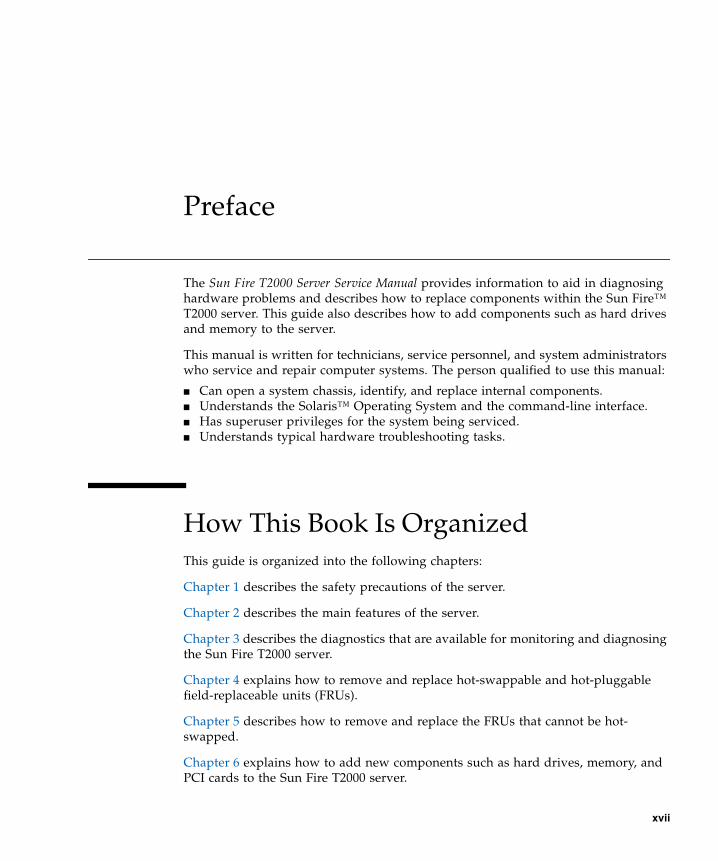
The Sun Fire T2000 Server Service Manual provides information to aid in diagnosinghardware problems and describes how to replace components within the Sun Fire™T2000 server. This guide also describes how to add components such as hard drivesand memory to the server.
This manual is written for technicians, service personnel, and system administratorswho service and repair computer systems. The person qualified to use this manual:
■ Can open a system chassis, identify, and replace internal components.■ Understands the Solaris™ Operating System and the command-line interface.■ Has superuser privileges for the system being serviced.■ Understands typical hardware troubleshooting tasks.
How This Book Is OrganizedThis guide is organized into the following chapters:
Chapter 1 describes the safety precautions of the server.
Chapter 2 describes the main features of the server.
Chapter 3 describes the diagnostics that are available for monitoring and diagnosingthe Sun Fire T2000 server.
Chapter 4 explains how to remove and replace hot-swappable and hot-pluggablefield-replaceable units (FRUs).
Chapter 5 describes how to remove and replace the FRUs that cannot be hot-swapped.
Chapter 6 explains how to add new components such as hard drives, memory, andPCI cards to the Sun Fire T2000 server.
xvii
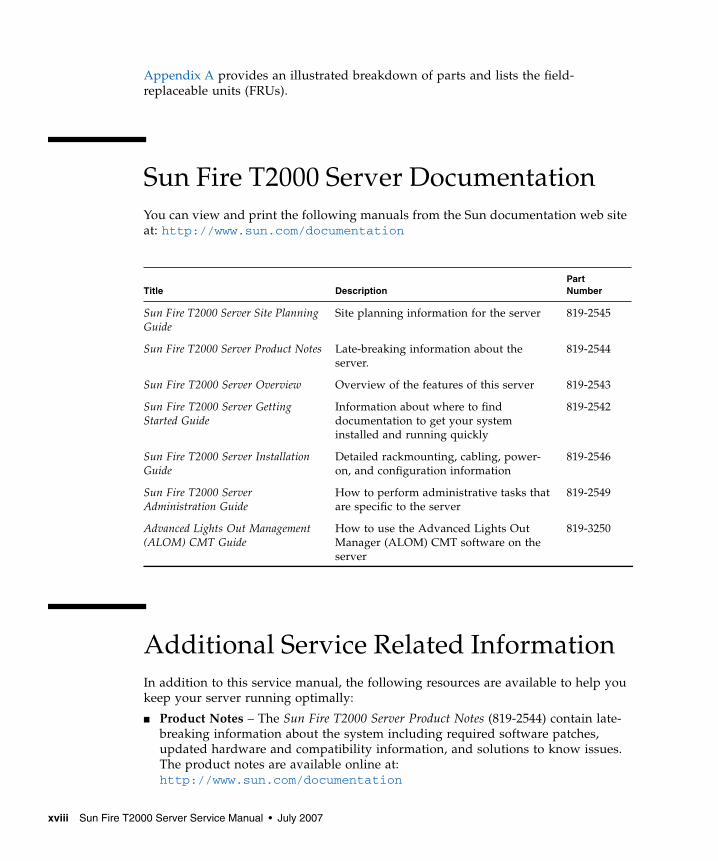
Appendix A provides an illustrated breakdown of parts and lists the field-replaceable units (FRUs).
Sun Fire T2000 Server DocumentationYou can view and print the following manuals from the Sun documentation web siteat: http://www.sun.com/documentation
Additional Service Related InformationIn addition to this service manual, the following resources are available to help youkeep your server running optimally:
■ Product Notes – The Sun Fire T2000 Server Product Notes (819-2544) contain late-breaking information about the system including required software patches,updated hardware and compatibility information, and solutions to know issues.The product notes are available online at:http://www.sun.com/documentation
Title DescriptionPartNumber
Sun Fire T2000 Server Site PlanningGuide
Site planning information for the server 819-2545
Sun Fire T2000 Server Product Notes Late-breaking information about theserver.
819-2544
Sun Fire T2000 Server Overview Overview of the features of this server 819-2543
Sun Fire T2000 Server GettingStarted Guide
Information about where to finddocumentation to get your systeminstalled and running quickly
819-2542
Sun Fire T2000 Server InstallationGuide
Detailed rackmounting, cabling, power-on, and configuration information
819-2546
Sun Fire T2000 ServerAdministration Guide
How to perform administrative tasks thatare specific to the server
819-2549
Advanced Lights Out Management(ALOM) CMT Guide
How to use the Advanced Lights OutManager (ALOM) CMT software on theserver
819-3250
xviii Sun Fire T2000 Server Service Manual • July 2007
■ Release Notes – The Solaris OS release notes contain important information aboutthe Solaris OS. The release notes are available online at:http://www.sun.com/documentation
■ SunSolveSM Online – Provides a collection of support resources. Depending onthe level of your service contract, you have access to Sun patches, the Sun SystemHandbook, the SunSolve™ knowledge base, the Sun Support Forum, andadditional documents, bulletins, and related links. Access this site at:http://sunsolve.sun.com
■ Predictive Self-Healing Knowledge Database – You can access the knowledgearticle corresponding to a self-healing message by taking the Sun MessageIdentifier (SUNW-MSG-ID) and entering it into the field on this page:http://www.sun.com/msg
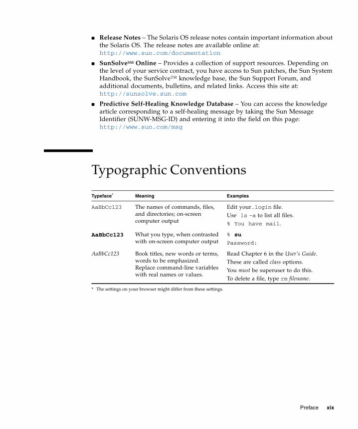
Typographic Conventions
Typeface*
* The settings on your browser might differ from these settings.
Meaning Examples
AaBbCc123 The names of commands, files,and directories; on-screencomputer output
Edit your.login file.Use ls -a to list all files.% You have mail.
AaBbCc123 What you type, when contrastedwith on-screen computer output
% su
Password:
AaBbCc123 Book titles, new words or terms,words to be emphasized.Replace command-line variableswith real names or values.
Read Chapter 6 in the User’s Guide.These are called class options.You must be superuser to do this.To delete a file, type rm filename.
Preface xix
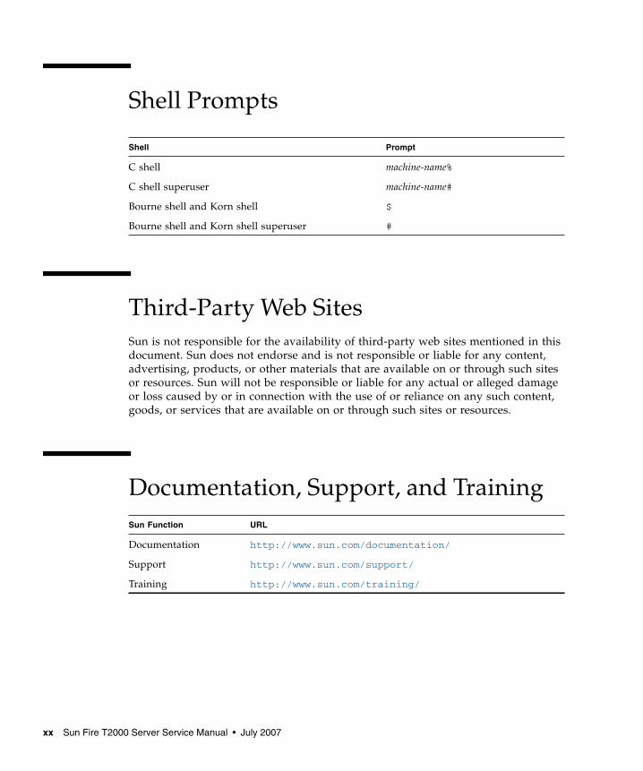
Shell Prompts
Third-Party Web SitesSun is not responsible for the availability of third-party web sites mentioned in thisdocument. Sun does not endorse and is not responsible or liable for any content,advertising, products, or other materials that are available on or through such sitesor resources. Sun will not be responsible or liable for any actual or alleged damageor loss caused by or in connection with the use of or reliance on any such content,goods, or services that are available on or through such sites or resources.
Documentation, Support, and Training
Shell Prompt
C shell machine-name%
C shell superuser machine-name#
Bourne shell and Korn shell $
Bourne shell and Korn shell superuser #
Sun Function URL
Documentation http://www.sun.com/documentation/
Support http://www.sun.com/support/
Training http://www.sun.com/training/
xx Sun Fire T2000 Server Service Manual • July 2007
Sun Welcomes Your CommentsSun is interested in improving its documentation and welcomes your comments andsuggestions. You can submit your comments by going to:
http://www.sun.com/hwdocs/feedback
Please include the title and part number of your document with your feedback:
Sun Fire T2000 Server Service Manual, part number 819-2548-14
Preface xxi

xxii Sun Fire T2000 Server Service Manual • July 2007
CHAPTER 1
Safety Information
This chapter provides important safety information for servicing the server.
The following topics are covered:
■ Section 1.1, “Safety Information” on page 1-1■ Section 1.2, “Safety Symbols” on page 1-1■ Section 1.3, “Electrostatic Discharge Safety” on page 1-2
1.1 Safety InformationThis section describes safety information you need to know prior to removing orinstalling parts in the server.
For your protection, observe the following safety precautions when setting up yourequipment:
■ Follow all Sun standard cautions, warnings, and instructions marked on theequipment and described in Important Safety Information for Sun Hardware Systems,816-7190.
■ Ensure that the voltage and frequency of your power source match the voltageand frequency inscribed on the equipment’s electrical rating label.
■ Follow the electrostatic discharge safety practices as described in Section 1.3,“Electrostatic Discharge Safety” on page 1-2.
1.2 Safety SymbolsThe following symbols might appear in this document. Note their meanings:
1-1
Caution – There is a risk of personal injury and equipment damage. To avoidpersonal injury and equipment damage, follow the instructions.
Caution – Hot surface. Avoid contact. Surfaces are hot and might cause personalinjury if touched.
Caution – Hazardous voltages are present. To reduce the risk of electric shock anddanger to personal health, follow the instructions.
1.3 Electrostatic Discharge SafetyElectrostatic discharge (ESD) sensitive devices, such as the motherboard, PCI cards,hard drives, and memory cards require special handling.
Caution – The boards and hard drives contain electronic components that areextremely sensitive to static electricity. Ordinary amounts of static electricity fromclothing or the work environment can destroy components. Do not touch thecomponents along their connector edges.
1.3.1 Using an Antistatic Wrist StrapWear an antistatic wrist strap and use an antistatic mat when handling componentssuch as drive assemblies, boards, or cards. When servicing or removing servercomponents, attach an antistatic strap to your wrist and then to a metal area on thechassis. Do this after you disconnect the power cords from the server. Following thispractice equalizes the electrical potentials between you and the server.
1.3.2 Using an Antistatic MatPlace ESD-sensitive components such as the motherboard, memory, and other PCBcards on an antistatic mat.
1-2 Sun Fire T2000 Server Service Manual • July 2007
CHAPTER 2
Server Overview
This chapter provides an overview of the features of the server.
The following topics are covered:
■ Section 2.1, “Server Features” on page 2-2■ Section 2.2, “Chassis Identification” on page 2-9
2-1
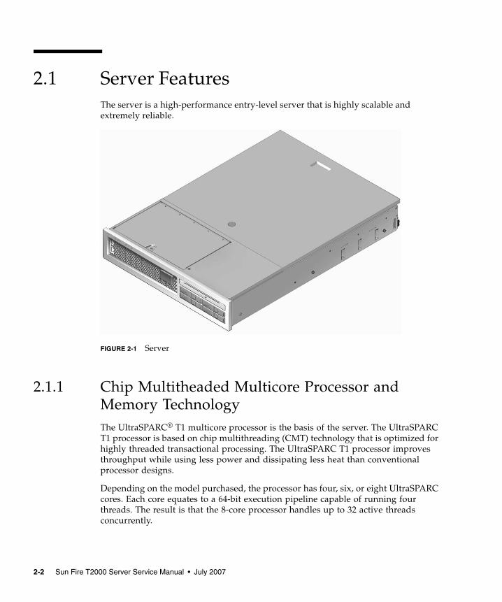
2.1 Server FeaturesThe server is a high-performance entry-level server that is highly scalable andextremely reliable.
FIGURE 2-1 Server
2.1.1 Chip Multitheaded Multicore Processor andMemory TechnologyThe UltraSPARC® T1 multicore processor is the basis of the server. The UltraSPARCT1 processor is based on chip multithreading (CMT) technology that is optimized forhighly threaded transactional processing. The UltraSPARC T1 processor improvesthroughput while using less power and dissipating less heat than conventionalprocessor designs.
Depending on the model purchased, the processor has four, six, or eight UltraSPARCcores. Each core equates to a 64-bit execution pipeline capable of running fourthreads. The result is that the 8-core processor handles up to 32 active threadsconcurrently.
2-2 Sun Fire T2000 Server Service Manual • July 2007
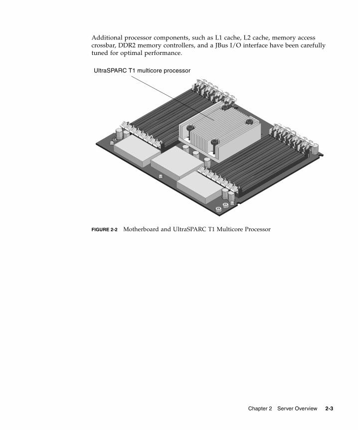
Additional processor components, such as L1 cache, L2 cache, memory accesscrossbar, DDR2 memory controllers, and a JBus I/O interface have been carefullytuned for optimal performance.
FIGURE 2-2 Motherboard and UltraSPARC T1 Multicore Processor
UltraSPARC T1 multicore processor
Chapter 2 Server Overview 2-3
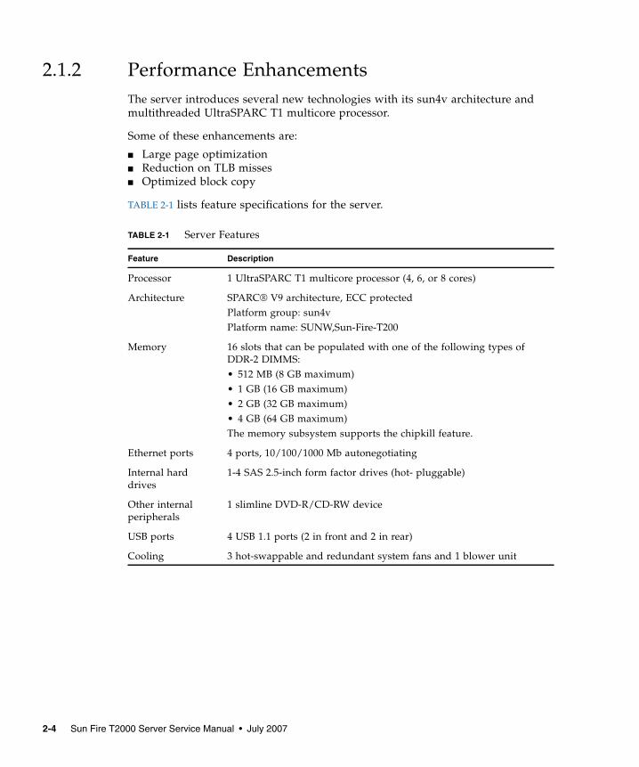
2.1.2 Performance EnhancementsThe server introduces several new technologies with its sun4v architecture andmultithreaded UltraSPARC T1 multicore processor.
Some of these enhancements are:
■ Large page optimization■ Reduction on TLB misses■ Optimized block copy
TABLE 2-1 lists feature specifications for the server.
TABLE 2-1 Server Features
Feature Description
Processor 1 UltraSPARC T1 multicore processor (4, 6, or 8 cores)
Architecture SPARC® V9 architecture, ECC protectedPlatform group: sun4vPlatform name: SUNW,Sun-Fire-T200
Memory 16 slots that can be populated with one of the following types ofDDR-2 DIMMS:• 512 MB (8 GB maximum)• 1 GB (16 GB maximum)• 2 GB (32 GB maximum)• 4 GB (64 GB maximum)The memory subsystem supports the chipkill feature.
Ethernet ports 4 ports, 10/100/1000 Mb autonegotiating
Internal harddrives
1-4 SAS 2.5-inch form factor drives (hot- pluggable)
Other internalperipherals
1 slimline DVD-R/CD-RW device
USB ports 4 USB 1.1 ports (2 in front and 2 in rear)
Cooling 3 hot-swappable and redundant system fans and 1 blower unit
2-4 Sun Fire T2000 Server Service Manual • July 2007
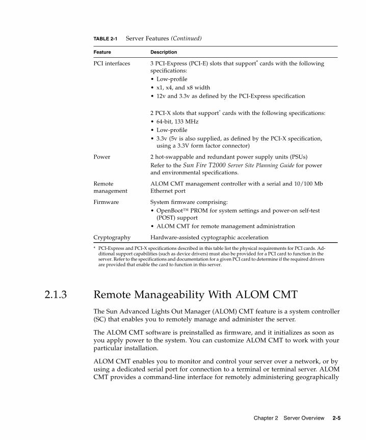
2.1.3 Remote Manageability With ALOM CMTThe Sun Advanced Lights Out Manager (ALOM) CMT feature is a system controller(SC) that enables you to remotely manage and administer the server.
The ALOM CMT software is preinstalled as firmware, and it initializes as soon asyou apply power to the system. You can customize ALOM CMT to work with yourparticular installation.
ALOM CMT enables you to monitor and control your server over a network, or byusing a dedicated serial port for connection to a terminal or terminal server. ALOMCMT provides a command-line interface for remotely administering geographically
PCI interfaces 3 PCI-Express (PCI-E) slots that support* cards with the followingspecifications:• Low-profile• x1, x4, and x8 width• 12v and 3.3v as defined by the PCI-Express specification
2 PCI-X slots that support* cards with the following specifications:• 64-bit, 133 MHz• Low-profile• 3.3v (5v is also supplied, as defined by the PCI-X specification,
using a 3.3V form factor connector)
Power 2 hot-swappable and redundant power supply units (PSUs)Refer to the Sun Fire T2000 Server Site Planning Guide for powerand environmental specifications.
Remotemanagement
ALOM CMT management controller with a serial and 10/100 MbEthernet port
Firmware System firmware comprising:• OpenBoot™ PROM for system settings and power-on self-test
(POST) support• ALOM CMT for remote management administration
Cryptography Hardware-assisted cyptographic acceleration
* PCI-Express and PCI-X specifications described in this table list the physical requirements for PCI cards. Ad-ditional support capabilities (such as device drivers) must also be provided for a PCI card to function in theserver. Refer to the specifications and documentation for a given PCI card to determine if the required driversare provided that enable the card to function in this server.
TABLE 2-1 Server Features (Continued)
Feature Description
Chapter 2 Server Overview 2-5
distributed or physically inaccessible machines. In addition, ALOM CMT enablesyou to run diagnostics (such as POST) remotely that would otherwise requirephysical proximity to the server’s serial port.
You can configure ALOM CMT to send email alerts of hardware failures, hardwarewarnings, and other events related to the server or to ALOM CMT. The ALOM CMTcircuitry runs independently of the server, using the server’s standby power.Therefore, ALOM CMT firmware and software continue to function when the serveroperating system goes offline or when the server is powered off. ALOM CMTmonitors the following server components:
■ CPU temperature conditions■ Hard drive status■ Enclosure thermal conditions■ Fan speed and status■ Power supply status■ Voltage levels■ Faults detected by POST (power-on self-test)■ Solaris Predictive Self-Healing (PSH) diagnostic facilities
For information about configuring and using the ALOM system controller, refer tothe latest Advanced Lights Out Manager (ALOM) CMT Guide.
2.1.4 System Reliability, Availability, and ServiceabilityReliability, availability, and serviceability (RAS) are aspects of a system’s design thataffect its ability to operate continuously and to minimize the time necessary toservice the system. Reliability refers to a system’s ability to operate continuouslywithout failures and to maintain data integrity. System availability refers to theability of a system to recover to an operational state after a failure, with minimalimpact. Serviceability relates to the time it takes to restore a system to servicefollowing a system failure. Together, reliability, availability, and serviceabilityfeatures provide for near continuous system operation.
To deliver high levels of reliability, availability, and serviceability, the server offersthe following features:
■ Hot-pluggable hard drives
■ Redundant, hot-swappable power supplies (two)
■ Redundant hot-swappable fan units (three)
■ Environmental monitoring
■ Error detection and correction for improved data integrity
■ Easy access for most component replacements
■ Extensive POST tests that automatically delete faulty components from theconfiguration
2-6 Sun Fire T2000 Server Service Manual • July 2007
■ PSH automated run-time diagnosis capability that takes faulty componentsoffline.
For more information about using RAS features, refer to the Sun Fire T2000 ServerAdministration Guide.
2.1.4.1 Hot-Pluggable and Hot-Swappable ComponentsThe server hardware supports hot-plugging or hot-swapping of the chassis-mountedhard drives, fans, power supplies, and the rear blower. Using the proper softwarecommands, you can install or remove these components while the server is running.Hot-plug and hot-swap technologies significantly increase the server’s serviceabilityand availability by providing the ability to replace hard drives, fan units, rearblower, and power supplies without service disruption.
2.1.4.2 Power Supply Redundancy
The server features two hot-swappable power supplies, which enable the systemto continue operating should a power supply or power sources fail.
The server also has a single hot-swappable blower unit that works in conjunctionwith the power supply fans to provide cooling for the internal hard drives. If theblower unit fails, the two power supply fan units provide enough cooling for thehard drive bay to keep the server running.
2.1.4.3 Fan Redundancy
The server features three hot-swappable system fans. Multiple fans enable the serverto continue operating with adequate cooling in the event that one of the fans fails.
2.1.4.4 Environmental Monitoring
The server features an environmental monitoring subsystem designed to protect theserver and its components against:
■ Extreme temperatures■ Lack of adequate airflow through the system■ Power supply failures■ Hardware faults
Temperature sensors located throughout the server monitor the ambient temperatureof the server and internal components. The software and hardware ensure that thetemperatures within the enclosure do not exceed predetermined safe operatingranges. If the temperature observed by a sensor falls below a low-temperature
Chapter 2 Server Overview 2-7
threshold or rises above a high-temperature threshold, the monitoring subsystemsoftware lights the amber Service Required LEDs on the front and back panel. If thetemperature condition persists and reaches a critical threshold, the system initiates agraceful server shutdown.
All error and warning messages are sent to the system controller (SC), console, andare logged in the ALOM CMT log file. Additionally, some FRUs such as powersupplies provide LEDs that indicate a failure within the FRU.
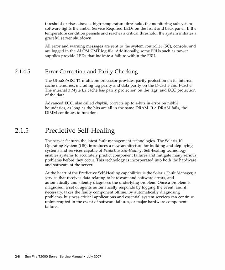
2.1.4.5 Error Correction and Parity Checking
The UltraSPARC T1 multicore processor provides parity protection on its internalcache memories, including tag parity and data parity on the D-cache and I-cache.The internal 3 Myte L2 cache has parity protection on the tags, and ECC protectionof the data.
Advanced ECC, also called chipkill, corrects up to 4-bits in error on nibbleboundaries, as long as the bits are all in the same DRAM. If a DRAM fails, theDIMM continues to function.
2.1.5 Predictive Self-HealingThe server features the latest fault management technologies. The Solaris 10Operating System (OS), introduces a new architecture for building and deployingsystems and services capable of Predictive Self-Healing. Self-healing technologyenables systems to accurately predict component failures and mitigate many seriousproblems before they occur. This technology is incorporated into both the hardwareand software of the server.
At the heart of the Predictive Self-Healing capabilities is the Solaris Fault Manager, aservice that receives data relating to hardware and software errors, andautomatically and silently diagnoses the underlying problem. Once a problem isdiagnosed, a set of agents automatically responds by logging the event, and ifnecessary, takes the faulty component offline. By automatically diagnosingproblems, business-critical applications and essential system services can continueuninterrupted in the event of software failures, or major hardware componentfailures.
2-8 Sun Fire T2000 Server Service Manual • July 2007
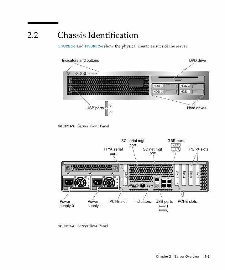
2.2 Chassis IdentificationFIGURE 2-3 and FIGURE 2-4 show the physical characteristics of the server.
FIGURE 2-3 Server Front Panel
FIGURE 2-4 Server Rear Panel
Hard drives
DVD drive
HDD 0
Indicators and buttons
HDD 2
HDD 1
HDD 3
2
3USB ports
Power Power PCI-E slot
SC serial mgt
SC net mgt
Indicators
PCI-X slotsTTYA serial
GBE ports20 1
3
01
USB ports
port
PCI-E slots
port
port
Slot 0
Slot 2
Slot 0
Slot 1
Slot 1
supply 1supply 0
Chapter 2 Server Overview 2-9
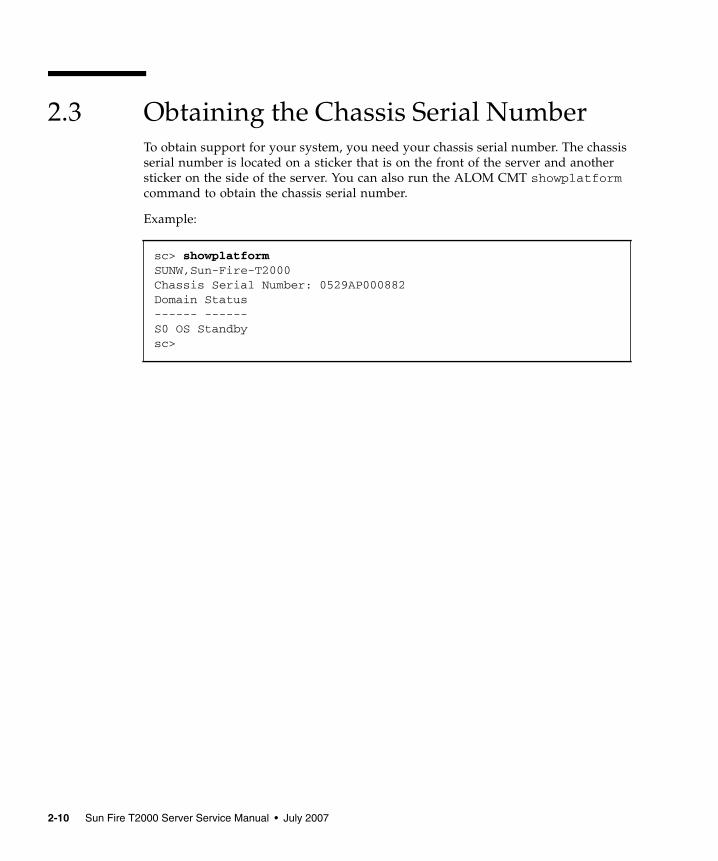
2.3 Obtaining the Chassis Serial NumberTo obtain support for your system, you need your chassis serial number. The chassisserial number is located on a sticker that is on the front of the server and anothersticker on the side of the server. You can also run the ALOM CMT showplatformcommand to obtain the chassis serial number.
Example:
sc> showplatformSUNW,Sun-Fire-T2000Chassis Serial Number: 0529AP000882Domain Status------ ------S0 OS Standbysc>
2-10 Sun Fire T2000 Server Service Manual • July 2007
CHAPTER 3
Server Diagnostics
This chapter describes the diagnostics that are available for monitoring andtroubleshooting the server.
This chapter is intended for technicians, service personnel, and systemadministrators who service and repair computer systems.
The following topics are covered:
■ Section 3.1, “Overview of Server Diagnostics” on page 3-1■ Section 3.2, “Using LEDs to Identify the State of Devices” on page 3-8■ Section 3.3, “Using ALOM CMT for Diagnosis and Repair Verification” on
page 3-16■ Section 3.4, “Running POST” on page 3-26■ Section 3.5, “Using the Solaris Predictive Self-Healing Feature” on page 3-40■ Section 3.6, “Collecting Information From Solaris OS Files and Commands” on
page 3-45■ Section 3.7, “Managing Components With Automatic System Recovery
Commands” on page 3-46■ Section 3.8, “Exercising the System With SunVTS” on page 3-49
3.1 Overview of Server DiagnosticsYou can use a variety of diagnostic tools, commands, and indicators to monitor andtroubleshoot a server:
■ LEDs – Provide a quick visual notification of the status of the server and of someof the FRUs.
3-1

■ ALOM CMT firmware – This system firmware runs on the system controller. Inaddition to providing the interface between the hardware and OS, ALOM CMTalso tracks and reports the health of key server components. ALOM CMT worksclosely with POST and Solaris Predictive Self-Healing technology to keep thesystem up and running even when there is a faulty component.
■ Power-on self-test (POST) – POST performs diagnostics on system componentsupon system reset to ensure the integrity of those components. POST isconfigureable and works with ALOM CMT to take faulty components offline ifneeded.
■ Solaris OS Predictive Self-Healing (PSH) – This technology continuouslymonitors the health of the CPU and memory, and works with ALOM CMT to takea faulty component offline if needed. The Predictive Self-Healing technologyenables systems to accurately predict component failures and mitigate manyserious problems before they occur.
■ Log files and console messages – Provide the standard Solaris OS log files andinvestigative commands that can be accessed and displayed on the device of yourchoice.
■ SunVTS™ – An application that exercises the system, provides hardwarevalidation, and discloses possible faulty components with recommendations forrepair.
The LEDs, ALOM CMT, Solaris OS PSH, and many of the log files and consolemessages are integrated. For example, a fault detected by the Solaris softwaredisplays the fault, logs it, passes information to ALOM CMT where it is logged, anddepending on the fault, might light one or more LEDs.
The diagnostic flow chart in FIGURE 3-1 and TABLE 3-1 describes an approach forusing the server diagnostics to identify a faulty field-replaceable unit (FRU). Thediagnostics you use, and the order in which you use them, depend on the nature ofthe problem you are troubleshooting, so you might perform some actions and notothers.
The flow chart assumes that you have already performed some troubleshooting suchas verification of proper installation, and visual inspection of cables and power, andpossibly performed a reset of the server (refer to the Sun Fire T2000 Server InstallationGuide and Sun Fire T2000 Server Administration Guide for details).
FIGURE 3-1 is a flow chart of the diagnostics available to troubleshoot faultyhardware. TABLE 3-1 has more information about each diagnostic in this chapter.
Note – POST is configured with ALOM CMT configuration variables (TABLE 3-9). Ifdiag_level is set to max (diag_level=max), POST reports all detected FRUsincluding memory devices with errors correctable by Predictive Self-Healing (PSH).Thus, not all memory devices detected by POST need to be replaced. SeeSection 3.4.5, “Correctable Errors Detected by POST” on page 3-36.
3-2 Sun Fire T2000 Server Service Manual • July 2007
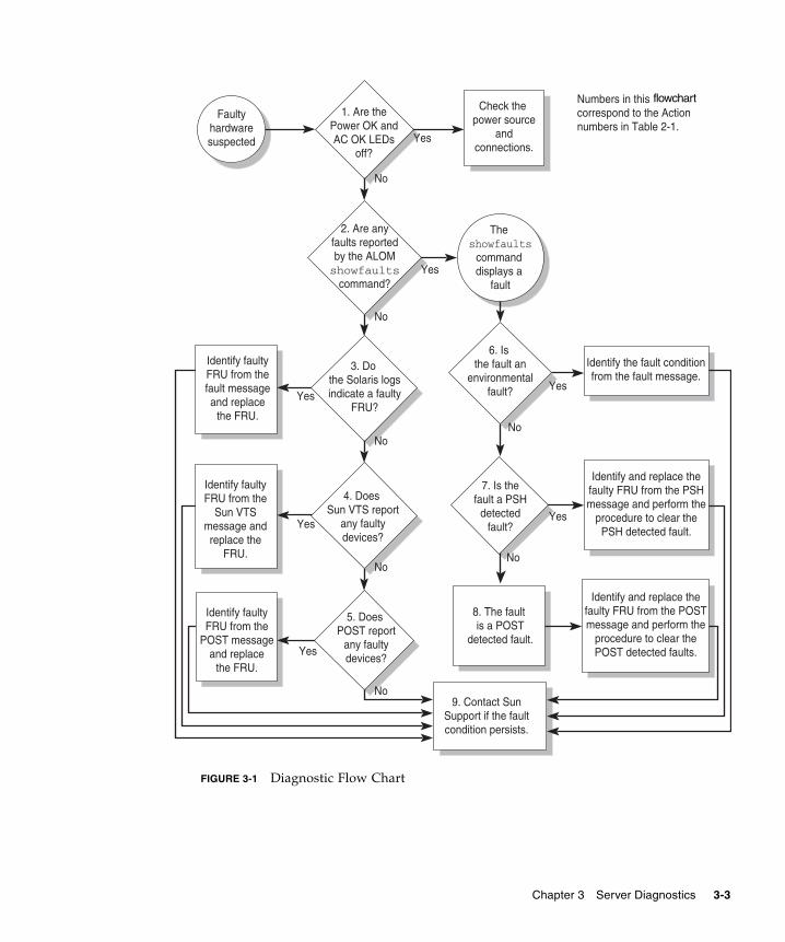
FIGURE 3-1 Diagnostic Flow Chart
Faultyhardwaresuspected
1. Are thePower OK andAC OK LEDs
off?
3. Do the Solaris logsindicate a faulty
FRU?
5. Does POST report
any faultydevices?
4. Does Sun VTS report
any faultydevices?
Numbers in this flow chart correspond to the Action numbers in Table 2-1.
2. Are anyfaults reportedby the ALOMshowfaults
command?
No
No
No
No
No
Yes
Yes
Yes
Check the power source
andconnections.
Identify faultyFRU from thefault messageand replace
the FRU.
Identify faultyFRU from the
Sun VTSmessage andreplace the
FRU.
Identify faultyFRU from the
POST messageand replace
the FRU.
9. Contact SunSupport if the faultcondition persists.
Yes
Yes
7. Is thefault a PSH
detectedfault?
6. Is the fault an
environmentalfault?
No
No
Yes
Yes
Identify and replace thefaulty FRU from the PSHmessage and perform the
procedure to clear thePSH detected fault.
Identify and replace thefaulty FRU from the POSTmessage and perform the
procedure to clear thePOST detected faults.
Identify the fault conditionfrom the fault message.
The showfaults
command displays a
fault
8. The fault is a POST
detected fault.
flowchart
Chapter 3 Server Diagnostics 3-3
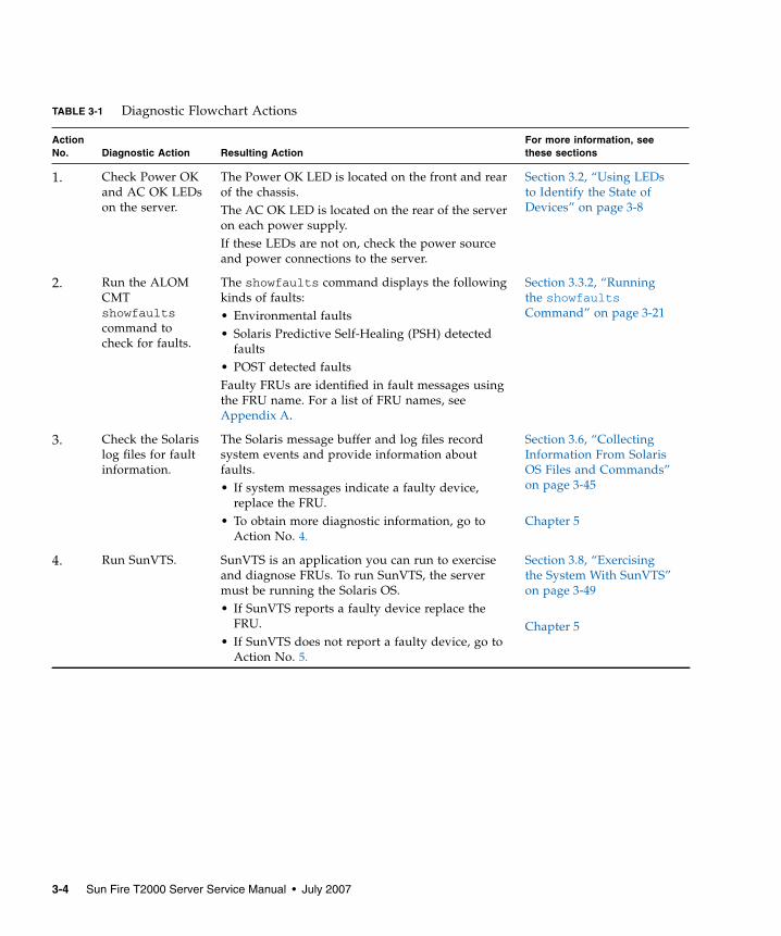
TABLE 3-1 Diagnostic Flowchart Actions
ActionNo. Diagnostic Action Resulting Action
For more information, seethese sections
1. Check Power OKand AC OK LEDson the server.
The Power OK LED is located on the front and rearof the chassis.The AC OK LED is located on the rear of the serveron each power supply.If these LEDs are not on, check the power sourceand power connections to the server.
Section 3.2, “Using LEDsto Identify the State ofDevices” on page 3-8
2. Run the ALOMCMTshowfaultscommand tocheck for faults.
The showfaults command displays the followingkinds of faults:• Environmental faults• Solaris Predictive Self-Healing (PSH) detected
faults• POST detected faultsFaulty FRUs are identified in fault messages usingthe FRU name. For a list of FRU names, seeAppendix A.
Section 3.3.2, “Runningthe showfaultsCommand” on page 3-21
3. Check the Solarislog files for faultinformation.
The Solaris message buffer and log files recordsystem events and provide information aboutfaults.• If system messages indicate a faulty device,
replace the FRU.• To obtain more diagnostic information, go to
Action No. 4.
Section 3.6, “CollectingInformation From SolarisOS Files and Commands”on page 3-45
Chapter 5
4. Run SunVTS. SunVTS is an application you can run to exerciseand diagnose FRUs. To run SunVTS, the servermust be running the Solaris OS.• If SunVTS reports a faulty device replace the
FRU.• If SunVTS does not report a faulty device, go to
Action No. 5.
Section 3.8, “Exercisingthe System With SunVTS”on page 3-49
Chapter 5
3-4 Sun Fire T2000 Server Service Manual • July 2007
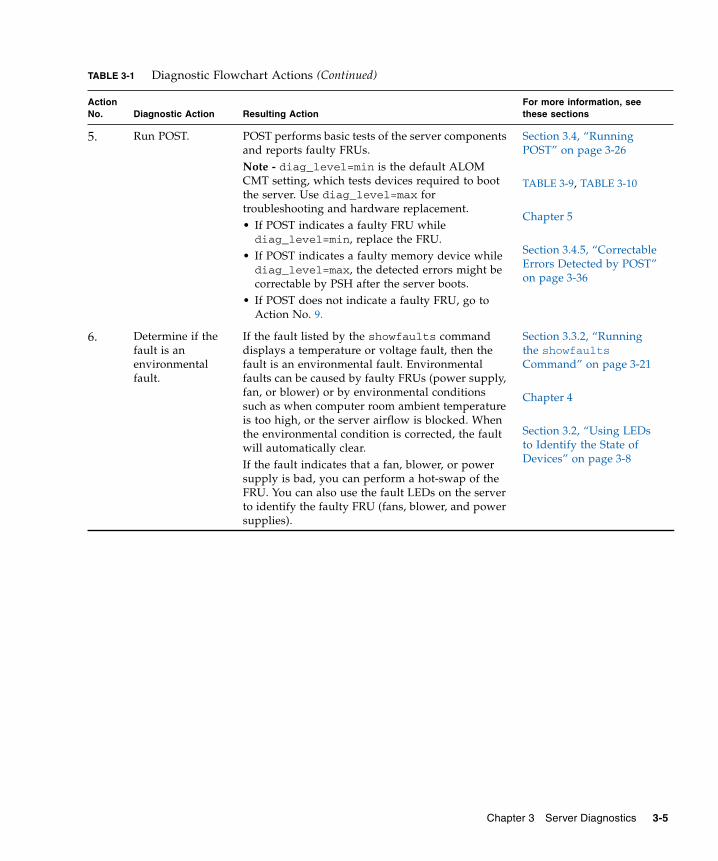
5. Run POST. POST performs basic tests of the server componentsand reports faulty FRUs.Note - diag_level=min is the default ALOMCMT setting, which tests devices required to bootthe server. Use diag_level=max fortroubleshooting and hardware replacement.• If POST indicates a faulty FRU whilediag_level=min, replace the FRU.
• If POST indicates a faulty memory device whilediag_level=max, the detected errors might becorrectable by PSH after the server boots.
• If POST does not indicate a faulty FRU, go toAction No. 9.
Section 3.4, “RunningPOST” on page 3-26
TABLE 3-9, TABLE 3-10
Chapter 5
Section 3.4.5, “CorrectableErrors Detected by POST”on page 3-36
6. Determine if thefault is anenvironmentalfault.
If the fault listed by the showfaults commanddisplays a temperature or voltage fault, then thefault is an environmental fault. Environmentalfaults can be caused by faulty FRUs (power supply,fan, or blower) or by environmental conditionssuch as when computer room ambient temperatureis too high, or the server airflow is blocked. Whenthe environmental condition is corrected, the faultwill automatically clear.If the fault indicates that a fan, blower, or powersupply is bad, you can perform a hot-swap of theFRU. You can also use the fault LEDs on the serverto identify the faulty FRU (fans, blower, and powersupplies).
Section 3.3.2, “Runningthe showfaultsCommand” on page 3-21
Chapter 4
Section 3.2, “Using LEDsto Identify the State ofDevices” on page 3-8
TABLE 3-1 Diagnostic Flowchart Actions (Continued)
ActionNo. Diagnostic Action Resulting Action
For more information, seethese sections
Chapter 3 Server Diagnostics 3-5

3.1.1 Memory Configuration and Fault HandlingA variety of features play a role in how the memory subsystem is configured andhow memory faults are handled. Understanding the underlying features helps youidentify and repair memory problems. This section describes how the memory isconfigured and how the server deals with memory faults.
3.1.1.1 Memory Configuration
In the server memory there are 16 slots that hold DDR-2 memory DIMMs in thefollowing DIMM sizes:
■ 512 MB (maximum of 8 GB)■ 1 GB (maximum of 16 GB)■ 2 GB (maximum of 32 GB)■ 4 GB (maximum of 64 GB)
7. Determine if thefault was detectedby PSH.
If the fault message displays the following text, thefault was detected by the Solaris Predictive Self-Healing software:Host detected fault
If the fault is a PSH detected fault, identify thefaulty FRU from the fault message and replace thefaulty FRU.After the FRU is replaced, perform the procedure toclear PSH detected faults.
Section 3.5, “Using theSolaris Predictive Self-Healing Feature” onpage 3-40
Chapter 5
Section 3.5.2, “ClearingPSH Detected Faults” onpage 3-44
8. Determine if thefault was detectedby POST.
POST performs basic tests of the server componentsand reports faulty FRUs. When POST detects afaulty FRU, it logs the fault and if possible, takesthe FRU offline. POST detected FRUs display thefollowing text in the fault message:FRU_name deemed faulty and disabled
In this case, replace the FRU and run the procedureto clear POST detected faults.
Section 3.4, “RunningPOST” on page 3-26
Chapter 5
Section 3.4.6, “ClearingPOST Detected Faults” onpage 3-39
9. Contact technicalsupport.
The majority of hardware faults are detected by theserver’s diagnostics. In rare cases a problem mightrequire additional troubleshooting. If you areunable to determine the cause of the problem,contact Sun for support.
Section 2.3, “Obtaining theChassis Serial Number”on page 2-10
TABLE 3-1 Diagnostic Flowchart Actions (Continued)
ActionNo. Diagnostic Action Resulting Action
For more information, seethese sections
3-6 Sun Fire T2000 Server Service Manual • July 2007
DIMMs are installed in groups of eight, called ranks (ranks 0 and 1). At a minimum,rank 0 must be fully populated with eight DIMMS of the same capacity. A secondrank of DIMMs of the same capacity, can be added to fill rank 1.
See Section 5.2.3, “Removing DIMMs” on page 5-12 for instructions about addingmemory to a server.
3.1.1.2 Memory Fault Handling
The server uses advanced ECC technology, also called chipkill, that corrects up to 4-bits in error on nibble boundaries, as long as the bits are all in the same DRAM. If aDRAM fails, the DIMM continues to function.
The following server features independently manage memory faults:
■ POST – Based on ALOM CMT configuration variables, POST runs when theserver is powered on. In normal operation, the default configuration of POST(diag_level=min), provides a check to ensure the server will boot. Normaloperation applies to any boot of the server not intended to test power-on errors,hardware upgrades, or repairs. Once the Solaris OS is running, PSH provides run-time diagnosis of faults.
When a memory fault is detected, POST displays the fault with the device nameof the faulty DIMMS, logs the fault, and disables the faulty DIMMs by placingthem in the ASR blacklist. For a given memory fault, POST disables half of thephysical memory in the system. When this offlining process occurs in normaloperation, you must replace the faulty DIMMs based on the fault message andenable the disabled DIMMs with the ALOM CMT enablecomponent command.
In other than normal operation, POST can be configured to run various levels oftesting (see TABLE 3-9 and TABLE 3-10) and can thoroughly test the memorysubsystem based on the purpose of the test. However, with thorough testingenabled (diag_level=max), POST finds faults and offlines memory devices witherrors that could be correctable with PSH. Thus, not all memory devices detectedand offlined by POST need to be replaced. See Section 3.4.5, “Correctable ErrorsDetected by POST” on page 3-36.
■ Solaris Predictive Self-Healing (PSH) technology – A feature of the Solaris OS,PSH uses the fault manager daemon (fmd) to watch for various kinds of faults.When a fault occurs, the fault is assigned a unique fault ID (UUID), and logged.PSH reports the fault and provides a recommended proactive replacement for theDIMMs associated with the fault.
Chapter 3 Server Diagnostics 3-7
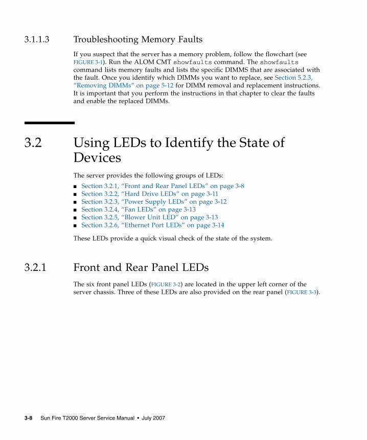
3.1.1.3 Troubleshooting Memory Faults
If you suspect that the server has a memory problem, follow the flowchart (seeFIGURE 3-1). Run the ALOM CMT showfaults command. The showfaultscommand lists memory faults and lists the specific DIMMS that are associated withthe fault. Once you identify which DIMMs you want to replace, see Section 5.2.3,“Removing DIMMs” on page 5-12 for DIMM removal and replacement instructions.It is important that you perform the instructions in that chapter to clear the faultsand enable the replaced DIMMs.
3.2 Using LEDs to Identify the State ofDevicesThe server provides the following groups of LEDs:
■ Section 3.2.1, “Front and Rear Panel LEDs” on page 3-8■ Section 3.2.2, “Hard Drive LEDs” on page 3-11■ Section 3.2.3, “Power Supply LEDs” on page 3-12■ Section 3.2.4, “Fan LEDs” on page 3-13■ Section 3.2.5, “Blower Unit LED” on page 3-13■ Section 3.2.6, “Ethernet Port LEDs” on page 3-14
These LEDs provide a quick visual check of the state of the system.
3.2.1 Front and Rear Panel LEDsThe six front panel LEDs (FIGURE 3-2) are located in the upper left corner of theserver chassis. Three of these LEDs are also provided on the rear panel (FIGURE 3-3).
3-8 Sun Fire T2000 Server Service Manual • July 2007
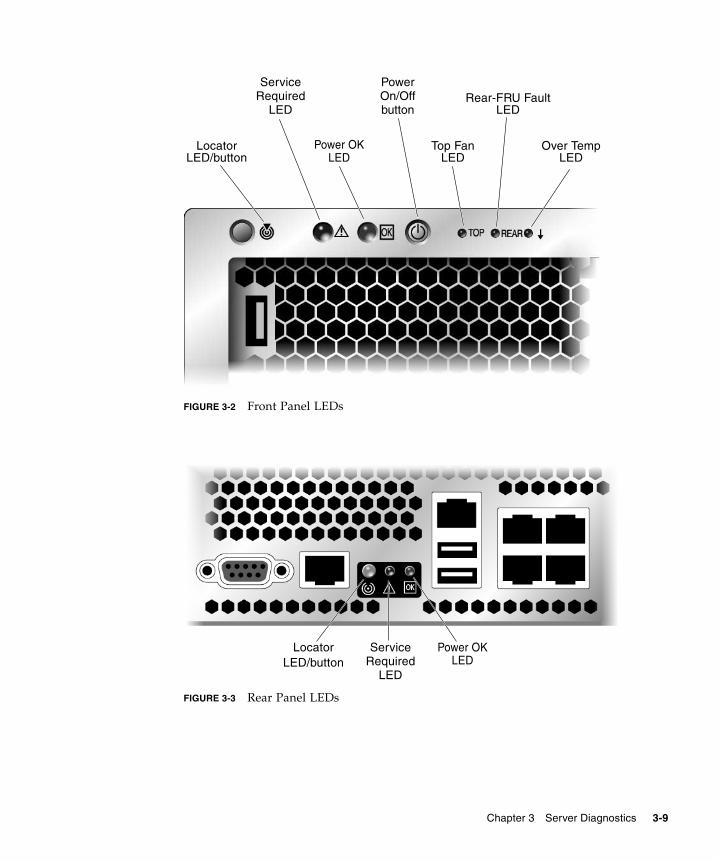
FIGURE 3-2 Front Panel LEDs
FIGURE 3-3 Rear Panel LEDs
LocatorLED/button
Power OKLED
Top FanLED
Rear-FRU FaultLED
Over TempLED
ServiceRequired
LED
PowerOn/Offbutton
LocatorLED/button
ServiceRequired
LED
Power OKLED
Chapter 3 Server Diagnostics 3-9
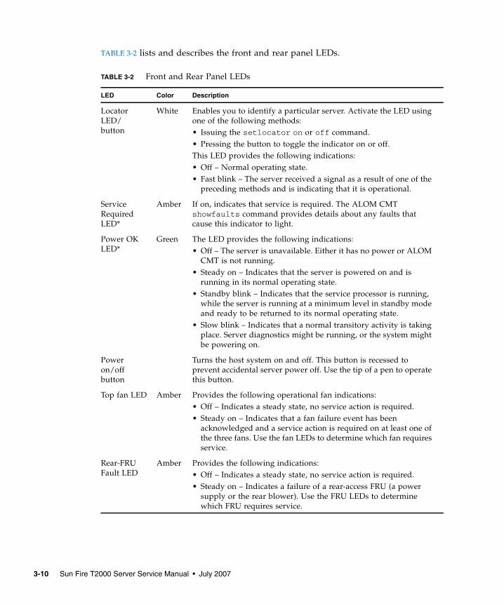
TABLE 3-2 lists and describes the front and rear panel LEDs.
TABLE 3-2 Front and Rear Panel LEDs
LED Color Description
LocatorLED/button
White Enables you to identify a particular server. Activate the LED usingone of the following methods:• Issuing the setlocator on or off command.• Pressing the button to toggle the indicator on or off.This LED provides the following indications:• Off – Normal operating state.• Fast blink – The server received a signal as a result of one of the
preceding methods and is indicating that it is operational.
ServiceRequiredLED*
Amber If on, indicates that service is required. The ALOM CMTshowfaults command provides details about any faults thatcause this indicator to light.
Power OKLED*
Green The LED provides the following indications:• Off – The server is unavailable. Either it has no power or ALOM
CMT is not running.• Steady on – Indicates that the server is powered on and is
running in its normal operating state.• Standby blink – Indicates that the service processor is running,
while the server is running at a minimum level in standby modeand ready to be returned to its normal operating state.
• Slow blink – Indicates that a normal transitory activity is takingplace. Server diagnostics might be running, or the system mightbe powering on.
Poweron/offbutton
Turns the host system on and off. This button is recessed toprevent accidental server power off. Use the tip of a pen to operatethis button.
Top fan LED Amber Provides the following operational fan indications:• Off – Indicates a steady state, no service action is required.• Steady on – Indicates that a fan failure event has been
acknowledged and a service action is required on at least one ofthe three fans. Use the fan LEDs to determine which fan requiresservice.
Rear-FRUFault LED
Amber Provides the following indications:• Off – Indicates a steady state, no service action is required.• Steady on – Indicates a failure of a rear-access FRU (a power
supply or the rear blower). Use the FRU LEDs to determinewhich FRU requires service.
3-10 Sun Fire T2000 Server Service Manual • July 2007
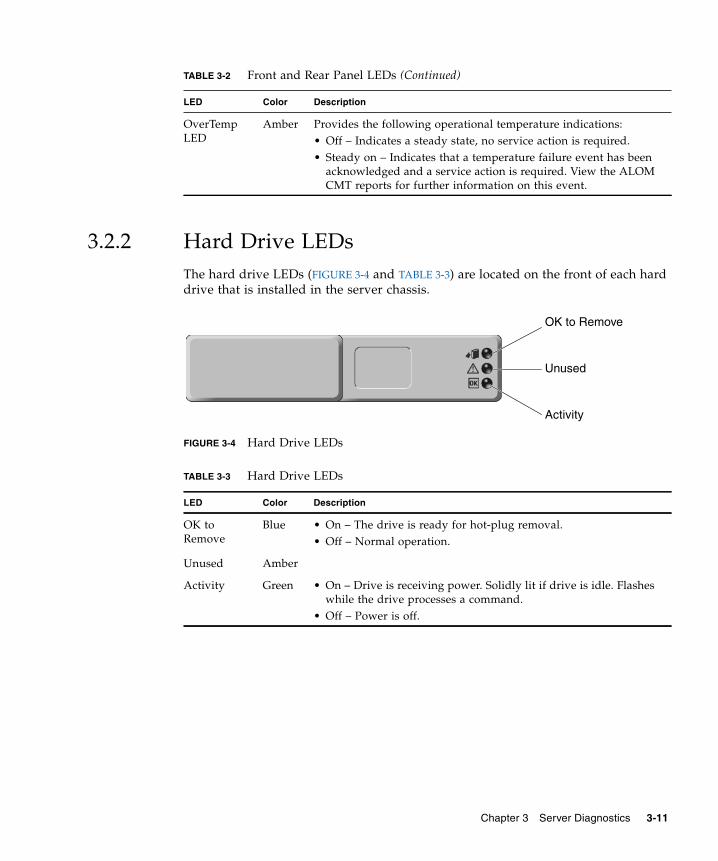
3.2.2 Hard Drive LEDsThe hard drive LEDs (FIGURE 3-4 and TABLE 3-3) are located on the front of each harddrive that is installed in the server chassis.
FIGURE 3-4 Hard Drive LEDs
OverTempLED
Amber Provides the following operational temperature indications:• Off – Indicates a steady state, no service action is required.• Steady on – Indicates that a temperature failure event has been
acknowledged and a service action is required. View the ALOMCMT reports for further information on this event.
TABLE 3-3 Hard Drive LEDs
LED Color Description
OK toRemove
Blue • On – The drive is ready for hot-plug removal.• Off – Normal operation.
Unused Amber
Activity Green • On – Drive is receiving power. Solidly lit if drive is idle. Flasheswhile the drive processes a command.
• Off – Power is off.
TABLE 3-2 Front and Rear Panel LEDs (Continued)
LED Color Description
Activity
Unused
OK to Remove
Chapter 3 Server Diagnostics 3-11
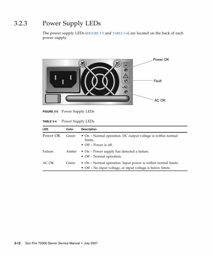
3.2.3 Power Supply LEDsThe power supply LEDs (FIGURE 3-5 and TABLE 3-4) are located on the back of eachpower supply.
FIGURE 3-5 Power Supply LEDs
TABLE 3-4 Power Supply LEDs
LED Color Description
Power OK Green • On – Normal operation. DC output voltage is within normallimits.
• Off – Power is off.
Failure Amber • On – Power supply has detected a failure.• Off – Normal operation.
AC OK Green • On – Normal operation. Input power is within normal limits.• Off – No input voltage, or input voltage is below limits.
AC OK
Fault
Power OK
3-12 Sun Fire T2000 Server Service Manual • July 2007
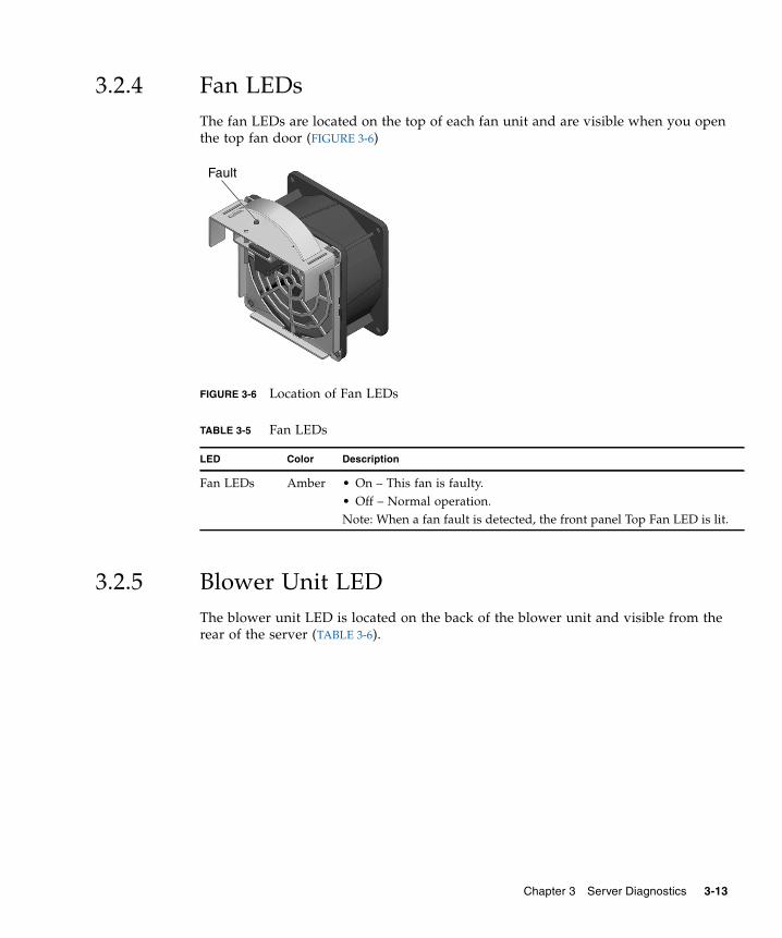
3.2.4 Fan LEDsThe fan LEDs are located on the top of each fan unit and are visible when you openthe top fan door (FIGURE 3-6)
FIGURE 3-6 Location of Fan LEDs
3.2.5 Blower Unit LEDThe blower unit LED is located on the back of the blower unit and visible from therear of the server (TABLE 3-6).
TABLE 3-5 Fan LEDs
LED Color Description
Fan LEDs Amber • On – This fan is faulty.• Off – Normal operation.Note: When a fan fault is detected, the front panel Top Fan LED is lit.
Fault
Chapter 3 Server Diagnostics 3-13
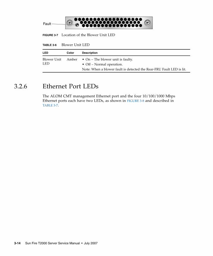
FIGURE 3-7 Location of the Blower Unit LED
3.2.6 Ethernet Port LEDsThe ALOM CMT management Ethernet port and the four 10/100/1000 MbpsEthernet ports each have two LEDs, as shown in FIGURE 3-8 and described inTABLE 3-7.
TABLE 3-6 Blower Unit LED
LED Color Description
Blower UnitLED
Amber • On – The blower unit is faulty.• Off – Normal operation.Note: When a blower fault is detected the Rear-FRU Fault LED is lit.
Fault
3-14 Sun Fire T2000 Server Service Manual • July 2007
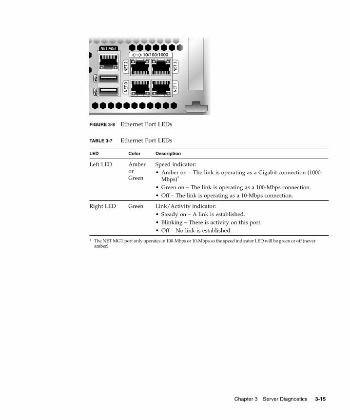
FIGURE 3-8 Ethernet Port LEDs
TABLE 3-7 Ethernet Port LEDs
LED Color Description
Left LED AmberorGreen
Speed indicator:• Amber on – The link is operating as a Gigabit connection (1000-
Mbps)*
• Green on – The link is operating as a 100-Mbps connection.• Off – The link is operating as a 10-Mbps connection.
* The NET MGT port only operates in 100-Mbps or 10-Mbps so the speed indicator LED will be green or off (neveramber).
Right LED Green Link/Activity indicator:• Steady on – A link is established.• Blinking – There is activity on this port.• Off – No link is established.
Chapter 3 Server Diagnostics 3-15
3.3 Using ALOM CMT for Diagnosis andRepair VerificationThe Sun Advanced Lights Out Manager (ALOM) CMT is a system controller in theserver that enables you to remotely manage and administer your server.
ALOM CMT enables you to run diagnostics remotely such as power-on self-test(POST), that would otherwise require physical proximity to the server’s serial port.You can also configure ALOM CMT to send email alerts of hardware failures,hardware warnings, and other events related to the server or to ALOM CMT.
The ALOM CMT circuitry runs independently of the server, using the server’sstandby power. Therefore, ALOM CMT firmware and software continue to functionwhen the server OS goes offline or when the server is powered off.
Note – Refer to the Advanced Lights Out Manager (ALOM) CMT Guide forcomprehensive ALOM CMT information.
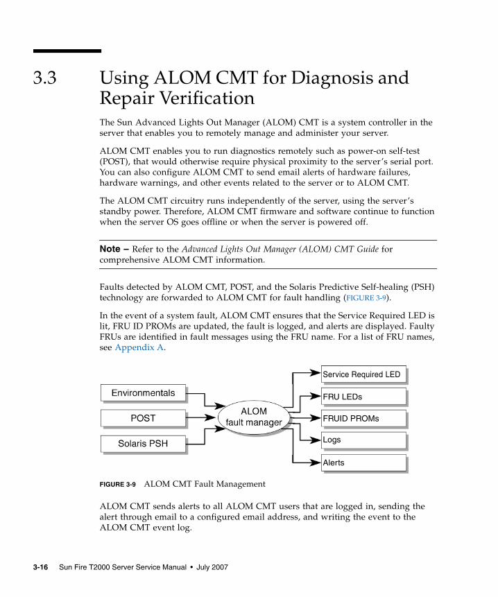
Faults detected by ALOM CMT, POST, and the Solaris Predictive Self-healing (PSH)technology are forwarded to ALOM CMT for fault handling (FIGURE 3-9).
In the event of a system fault, ALOM CMT ensures that the Service Required LED islit, FRU ID PROMs are updated, the fault is logged, and alerts are displayed. FaultyFRUs are identified in fault messages using the FRU name. For a list of FRU names,see Appendix A.
FIGURE 3-9 ALOM CMT Fault Management
ALOM CMT sends alerts to all ALOM CMT users that are logged in, sending thealert through email to a configured email address, and writing the event to theALOM CMT event log.
Service Required LED
FRU LEDs
FRUID PROMs
Logs
Alerts
3-16 Sun Fire T2000 Server Service Manual • July 2007
ALOM CMT can detect when a fault is no longer present and clears the fault inseveral ways:
■ Fault recovery – The system automatically detects that the fault condition is nolonger present. ALOM CMT extinguishes the Service Required LED and updatesthe FRU’s PROM, indicating that the fault is no longer present.
■ Fault repair – The fault has been repaired by human intervention. In most cases,ALOM CMT detects the repair and extinguishes the Service Required LED IfALOM CMT does not perform these actions, you must perform these tasksmanually with clearfault or enablecomponent commands.
ALOM CMT can detect the removal of a FRU, in many cases even if the FRU isremoved while ALOM CMT is powered off. This enables ALOM CMT to know thata fault, diagnosed to a specific FRU, has been repaired. The ALOM CMTclearfault command enables you to manually clear certain types of faults withouta FRU replacement or if ALOM CMT was unable to automatically detect the FRUreplacement.
Note – ALOM CMT does not automatically detect hard drive replacement.
Many environmental faults can automatically recover. A temperature that isexceeding a threshold might return to normal limits. An unplugged a power supplycan be plugged in, and so on. Recovery of environmental faults is automaticallydetected. Recovery events are reported using one of two forms:
■ fru at location is OK.■ sensor at location is within normal range.
Environmental faults can be repaired through hot removal of the faulty FRU. FRUremoval is automatically detected by the environmental monitoring and all faultsassociated with the removed FRU are cleared. The message for that case, and thealert sent for all FRU removals is:
fru at location has been removed.
There is no ALOM CMT command to manually repair an environmental fault.
The Solaris Predictive Self-Healing technology does not monitor the hard drive forfaults. As a result, ALOM CMT does not recognize hard drive faults, and will notlight the fault LEDs on either the chassis or the hard drive itself. Use the Solarismessage files to view hard drive faults. See Section 3.6, “Collecting InformationFrom Solaris OS Files and Commands” on page 3-45.
Chapter 3 Server Diagnostics 3-17
3.3.1 Running ALOM CMT Service-Related CommandsThis section describes the ALOM CMT commands that are commonly used forservice-related activities.
3.3.1.1 Connecting to ALOM CMT
Before you can run ALOM CMT commands, you must connect to the ALOM CMT.There are several ways to connect to the system controller:
■ Connect an ASCII terminal directly to the serial management port.
■ Use the telnet command to connect to ALOM CMT through an Ethernetconnection on the network management port.
Note – Refer to the Advanced Lights Out Manager (ALOM) CMT Guide forinstructions on configuring and connecting to ALOM CMT.
3.3.1.2 Switching Between the System Console and ALOM CMT■ To switch from the console output to the ALOM CMT sc> prompt, type #.
(Hash-Period).
■ To switch from the sc> prompt to the console, type console.
3-18 Sun Fire T2000 Server Service Manual • July 2007
3.3.1.3 Service-Related ALOM CMT Commands
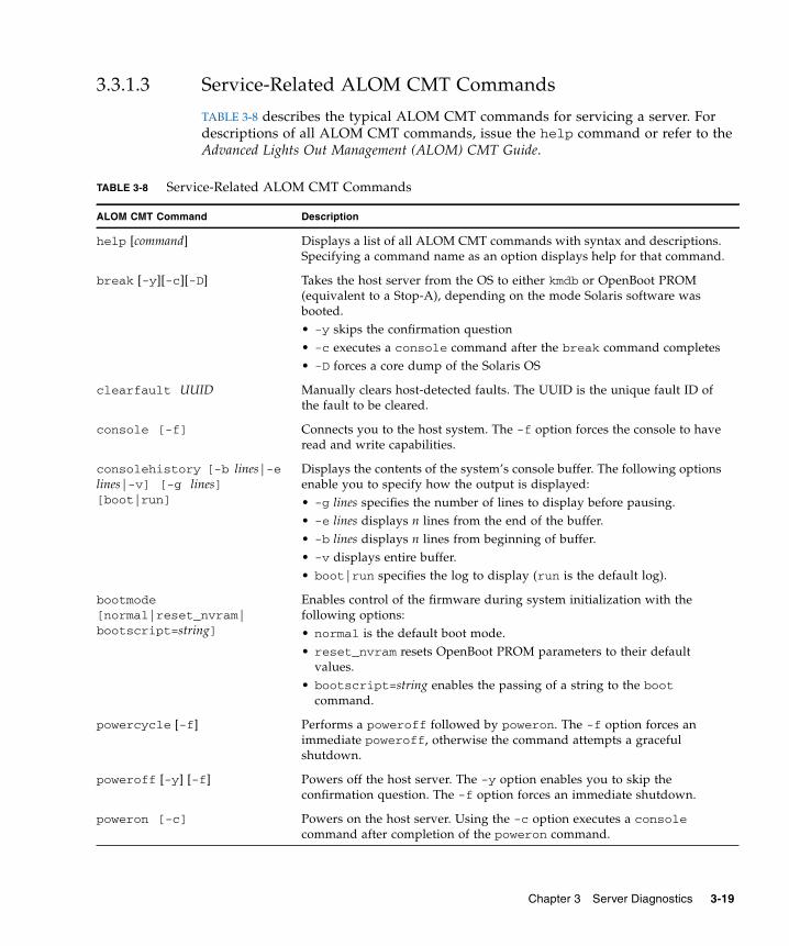
TABLE 3-8 describes the typical ALOM CMT commands for servicing a server. Fordescriptions of all ALOM CMT commands, issue the help command or refer to theAdvanced Lights Out Management (ALOM) CMT Guide.
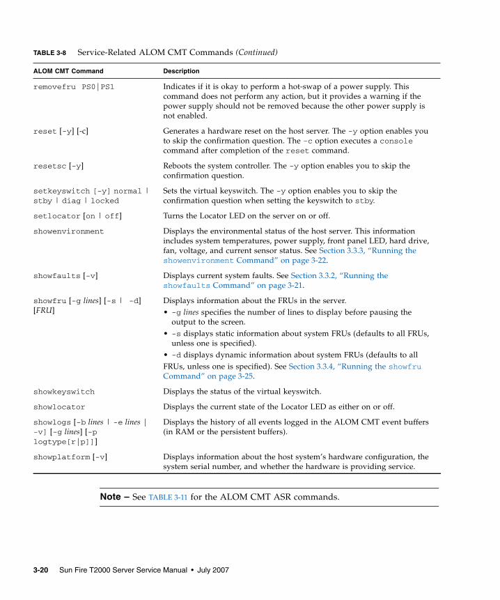
TABLE 3-8 Service-Related ALOM CMT Commands
ALOM CMT Command Description
help [command] Displays a list of all ALOM CMT commands with syntax and descriptions.Specifying a command name as an option displays help for that command.
break [-y][-c][-D] Takes the host server from the OS to either kmdb or OpenBoot PROM(equivalent to a Stop-A), depending on the mode Solaris software wasbooted.• -y skips the confirmation question• -c executes a console command after the break command completes• -D forces a core dump of the Solaris OS
clearfault UUID Manually clears host-detected faults. The UUID is the unique fault ID ofthe fault to be cleared.
console [-f] Connects you to the host system. The -f option forces the console to haveread and write capabilities.
consolehistory [-b lines|-elines|-v] [-g lines][boot|run]
Displays the contents of the system’s console buffer. The following optionsenable you to specify how the output is displayed:• -g lines specifies the number of lines to display before pausing.• -e lines displays n lines from the end of the buffer.• -b lines displays n lines from beginning of buffer.• -v displays entire buffer.• boot|run specifies the log to display (run is the default log).
bootmode[normal|reset_nvram|bootscript=string]
Enables control of the firmware during system initialization with thefollowing options:• normal is the default boot mode.• reset_nvram resets OpenBoot PROM parameters to their default
values.• bootscript=string enables the passing of a string to the boot
command.
powercycle [-f] Performs a poweroff followed by poweron. The -f option forces animmediate poweroff, otherwise the command attempts a gracefulshutdown.
poweroff [-y] [-f] Powers off the host server. The -y option enables you to skip theconfirmation question. The -f option forces an immediate shutdown.
poweron [-c] Powers on the host server. Using the -c option executes a consolecommand after completion of the poweron command.
Chapter 3 Server Diagnostics 3-19
Note – See TABLE 3-11 for the ALOM CMT ASR commands.
removefru PS0|PS1 Indicates if it is okay to perform a hot-swap of a power supply. Thiscommand does not perform any action, but it provides a warning if thepower supply should not be removed because the other power supply isnot enabled.
reset [-y] [-c] Generates a hardware reset on the host server. The -y option enables youto skip the confirmation question. The -c option executes a consolecommand after completion of the reset command.
resetsc [-y] Reboots the system controller. The -y option enables you to skip theconfirmation question.
setkeyswitch [-y] normal |stby | diag | locked
Sets the virtual keyswitch. The -y option enables you to skip theconfirmation question when setting the keyswitch to stby.
setlocator [on | off] Turns the Locator LED on the server on or off.
showenvironment Displays the environmental status of the host server. This informationincludes system temperatures, power supply, front panel LED, hard drive,fan, voltage, and current sensor status. See Section 3.3.3, “Running theshowenvironment Command” on page 3-22.
showfaults [-v] Displays current system faults. See Section 3.3.2, “Running theshowfaults Command” on page 3-21.
showfru [-g lines] [-s | -d][FRU]
Displays information about the FRUs in the server.• -g lines specifies the number of lines to display before pausing the
output to the screen.• -s displays static information about system FRUs (defaults to all FRUs,
unless one is specified).• -d displays dynamic information about system FRUs (defaults to allFRUs, unless one is specified). See Section 3.3.4, “Running the showfruCommand” on page 3-25.
showkeyswitch Displays the status of the virtual keyswitch.
showlocator Displays the current state of the Locator LED as either on or off.
showlogs [-b lines | -e lines |-v] [-g lines] [-plogtype[r|p]]]
Displays the history of all events logged in the ALOM CMT event buffers(in RAM or the persistent buffers).
showplatform [-v] Displays information about the host system’s hardware configuration, thesystem serial number, and whether the hardware is providing service.
TABLE 3-8 Service-Related ALOM CMT Commands (Continued)
ALOM CMT Command Description
3-20 Sun Fire T2000 Server Service Manual • July 2007
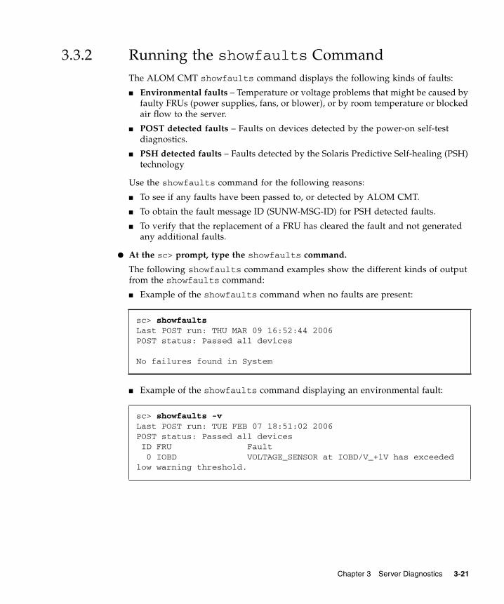
3.3.2 Running the showfaults CommandThe ALOM CMT showfaults command displays the following kinds of faults:
■ Environmental faults – Temperature or voltage problems that might be caused byfaulty FRUs (power supplies, fans, or blower), or by room temperature or blockedair flow to the server.
■ POST detected faults – Faults on devices detected by the power-on self-testdiagnostics.
■ PSH detected faults – Faults detected by the Solaris Predictive Self-healing (PSH)technology
Use the showfaults command for the following reasons:
■ To see if any faults have been passed to, or detected by ALOM CMT.
■ To obtain the fault message ID (SUNW-MSG-ID) for PSH detected faults.
■ To verify that the replacement of a FRU has cleared the fault and not generatedany additional faults.
● At the sc> prompt, type the showfaults command.
The following showfaults command examples show the different kinds of outputfrom the showfaults command:
■ Example of the showfaults command when no faults are present:
■ Example of the showfaults command displaying an environmental fault:
sc> showfaultsLast POST run: THU MAR 09 16:52:44 2006POST status: Passed all devices
No failures found in System
sc> showfaults -vLast POST run: TUE FEB 07 18:51:02 2006POST status: Passed all devices ID FRU Fault 0 IOBD VOLTAGE_SENSOR at IOBD/V_+1V has exceededlow warning threshold.
Chapter 3 Server Diagnostics 3-21
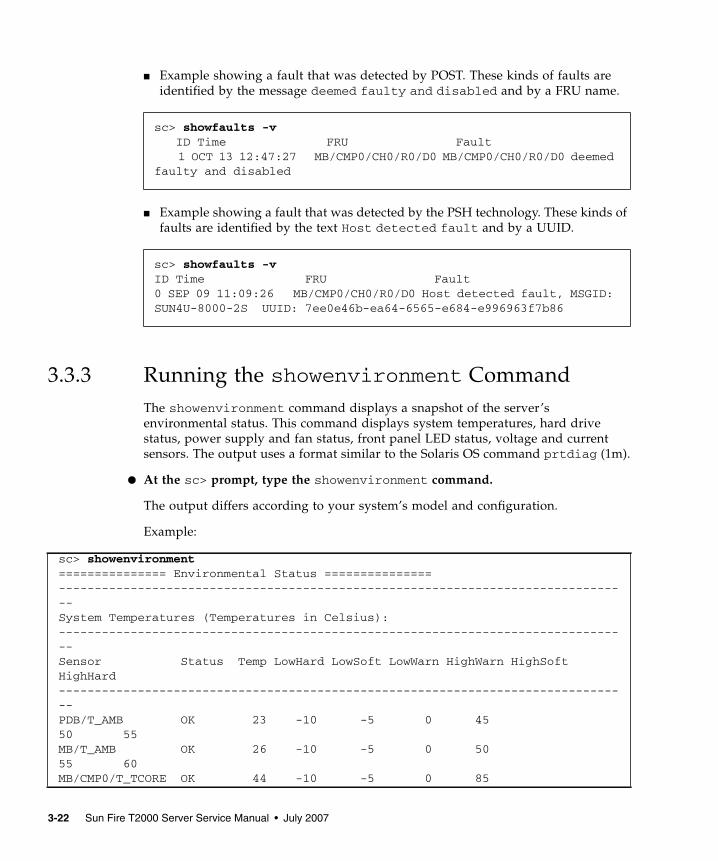
■ Example showing a fault that was detected by POST. These kinds of faults areidentified by the message deemed faulty and disabled and by a FRU name.
■ Example showing a fault that was detected by the PSH technology. These kinds offaults are identified by the text Host detected fault and by a UUID.
3.3.3 Running the showenvironment CommandThe showenvironment command displays a snapshot of the server’senvironmental status. This command displays system temperatures, hard drivestatus, power supply and fan status, front panel LED status, voltage and currentsensors. The output uses a format similar to the Solaris OS command prtdiag (1m).
● At the sc> prompt, type the showenvironment command.
The output differs according to your system’s model and configuration.
Example:
sc> showfaults -v ID Time FRU Fault
1 OCT 13 12:47:27 MB/CMP0/CH0/R0/D0 MB/CMP0/CH0/R0/D0 deemedfaulty and disabled
sc> showfaults -vID Time FRU Fault0 SEP 09 11:09:26 MB/CMP0/CH0/R0/D0 Host detected fault, MSGID:SUN4U-8000-2S UUID: 7ee0e46b-ea64-6565-e684-e996963f7b86
sc> showenvironment=============== Environmental Status ===============--------------------------------------------------------------------------------System Temperatures (Temperatures in Celsius):--------------------------------------------------------------------------------Sensor Status Temp LowHard LowSoft LowWarn HighWarn HighSoftHighHard--------------------------------------------------------------------------------PDB/T_AMB OK 23 -10 -5 0 4550 55MB/T_AMB OK 26 -10 -5 0 5055 60MB/CMP0/T_TCORE OK 44 -10 -5 0 85
3-22 Sun Fire T2000 Server Service Manual • July 2007
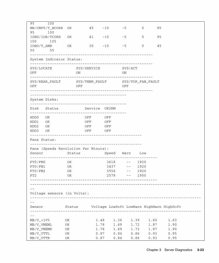
95 100MB/CMP0/T_BCORE OK 45 -10 -5 0 8595 100IOBD/IOB/TCORE OK 41 -10 -5 0 95100 105IOBD/T_AMB OK 30 -10 -5 0 4550 55--------------------------------------------------------System Indicator Status:--------------------------------------------------------SYS/LOCATE SYS/SERVICE SYS/ACTOFF ON ON--------------------------------------------------------SYS/REAR_FAULT SYS/TEMP_FAULT SYS/TOP_FAN_FAULTOFF OFF OFF----------------------------------------------------------------------------------------------------System Disks:--------------------------------------------Disk Status Service OK2RM--------------------------------------------HDD0 OK OFF OFFHDD1 OK OFF OFFHDD2 OK OFF OFFHDD3 OK OFF OFF---------------------------------------------------Fans Status:---------------------------------------------------Fans (Speeds Revolution Per Minute):Sensor Status Speed Warn Low----------------------------------------------------------FT0/FM0 OK 3618 -- 1920FT0/FM1 OK 3437 -- 1920FT0/FM2 OK 3556 -- 1920FT2 OK 2578 -- 1900------------------------------------------------------------------------------------------------------------------------------------------Voltage sensors (in Volts):--------------------------------------------------------------------------------Sensor Status Voltage LowSoft LowWarn HighWarn HighSoft--------------------------------------------------------------------------------MB/V_+1V5 OK 1.48 1.36 1.39 1.60 1.63MB/V_VMEML OK 1.78 1.69 1.72 1.87 1.90MB/V_VMEMR OK 1.78 1.69 1.72 1.87 1.90MB/V_VTTL OK 0.87 0.84 0.86 0.93 0.95MB/V_VTTR OK 0.87 0.84 0.86 0.93 0.95
Chapter 3 Server Diagnostics 3-23
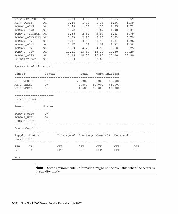
Note – Some environmental information might not be available when the server isin standby mode.
MB/V_+3V3STBY OK 3.33 3.13 3.16 3.53 3.59MB/V_VCORE OK 1.30 1.20 1.24 1.36 1.39IOBD/V_+1V5 OK 1.48 1.27 1.35 1.65 1.72IOBD/V_+1V8 OK 1.78 1.53 1.62 1.98 2.07IOBD/V_+3V3MAIN OK 3.38 2.80 2.97 3.63 3.79IOBD/V_+3V3STBY OK 3.33 2.80 2.97 3.63 3.79IOBD/V_+1V OK 1.11 0.93 0.99 1.21 1.26IOBD/V_+1V2 OK 1.17 1.02 1.08 1.32 1.38IOBD/V_+5V OK 5.09 4.25 4.50 5.50 5.75IOBD/V_-12V OK -12.11 -13.80 -13.20 -10.80 -10.20IOBD/V_+12V OK 12.18 10.20 10.80 13.20 13.80SC/BAT/V_BAT OK 3.03 -- 2.69 -- -------------------------------------------------------------System Load (in amps):-----------------------------------------------------------Sensor Status Load Warn Shutdown-----------------------------------------------------------MB/I_VCORE OK 25.280 80.000 88.000MB/I_VMEML OK 4.680 60.000 66.000MB/I_VMEMR OK 4.680 60.000 66.000---------------------------------------------------------------------------------Current sensors:----------------------Sensor Status----------------------IOBD/I_USB0 OKIOBD/I_USB1 OKFIOBD/I_USB OK------------------------------------------------------------------------------Power Supplies:------------------------------------------------------------------------------Supply Status Underspeed Overtemp Overvolt UndervoltOvercurrent------------------------------------------------------------------------------PS0 OK OFF OFF OFF OFF OFFPS1 OK OFF OFF OFF OFF OFF
sc>
3-24 Sun Fire T2000 Server Service Manual • July 2007
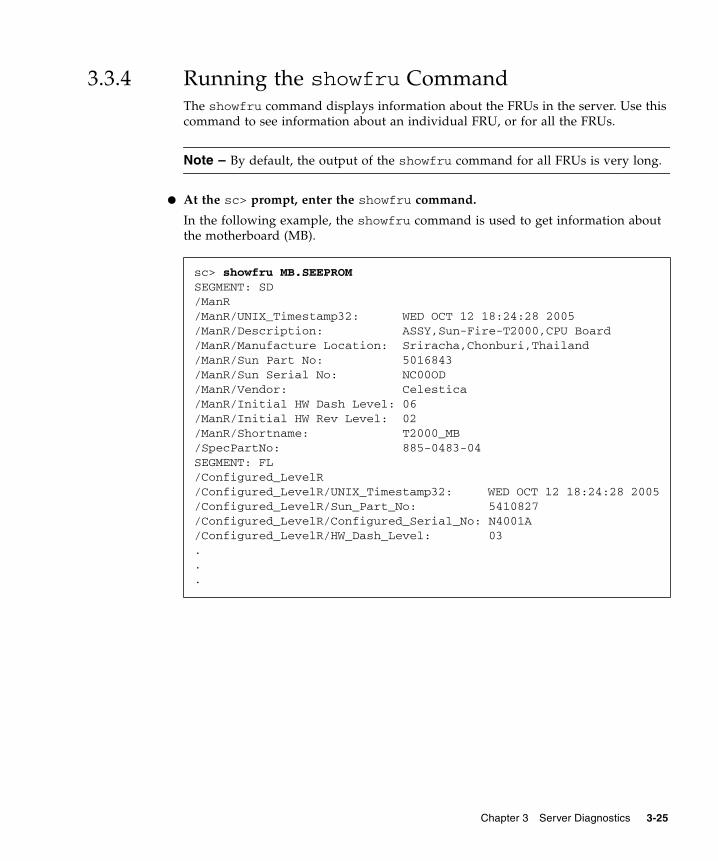
3.3.4 Running the showfru CommandThe showfru command displays information about the FRUs in the server. Use thiscommand to see information about an individual FRU, or for all the FRUs.
Note – By default, the output of the showfru command for all FRUs is very long.
● At the sc> prompt, enter the showfru command.
In the following example, the showfru command is used to get information aboutthe motherboard (MB).
sc> showfru MB.SEEPROMSEGMENT: SD/ManR/ManR/UNIX_Timestamp32: WED OCT 12 18:24:28 2005/ManR/Description: ASSY,Sun-Fire-T2000,CPU Board/ManR/Manufacture Location: Sriracha,Chonburi,Thailand/ManR/Sun Part No: 5016843/ManR/Sun Serial No: NC00OD/ManR/Vendor: Celestica/ManR/Initial HW Dash Level: 06/ManR/Initial HW Rev Level: 02/ManR/Shortname: T2000_MB/SpecPartNo: 885-0483-04SEGMENT: FL/Configured_LevelR/Configured_LevelR/UNIX_Timestamp32: WED OCT 12 18:24:28 2005/Configured_LevelR/Sun_Part_No: 5410827/Configured_LevelR/Configured_Serial_No: N4001A/Configured_LevelR/HW_Dash_Level: 03...
Chapter 3 Server Diagnostics 3-25
3.4 Running POSTPower-on self-test (POST) is a group of PROM-based tests that run when the serveris powered on or reset. POST checks the basic integrity of the critical hardwarecomponents in the server (CPU, memory, and I/O buses).
If POST detects a faulty component, the component is disabled automatically,preventing faulty hardware from potentially harming any software. If the system iscapable of running without the disabled component, the system will boot whenPOST is complete. For example, if one of the processor cores is deemed faulty byPOST, the core will be disabled, and the system will boot and run using theremaining cores.
In normal operation*, the default configuration of POST (diag_level=min),provides a sanity check to ensure the server will boot. Normal operation applies toany power on of the server not intended to test power-on errors, hardwareupgrades, or repairs. Once the Solaris OS is running, PSH provides run-timediagnosis of faults.
*Note – Earlier versions of firmware have max as the default setting for the POSTdiag_level variable. To set the default to min, use the ALOM CMT command,setsc diag_level min
For validating hardware upgrades or repairs, configure POST to run in maximummode (diag_level=max). Note that with maximum testing enabled, POST detectsand offlines memory devices with errors that could be correctable by PSH. Thus, notall memory devices detected by POST need to be replaced. See Section 3.4.5,“Correctable Errors Detected by POST” on page 3-36.
Note – Devices can be manually enabled or disabled using ASR commands (seeSection 3.7, “Managing Components With Automatic System Recovery Commands”on page 3-46).
3.4.1 Controlling How POST RunsThe server can be configured for normal, extensive, or no POST execution. You canalso control the level of tests that run, the amount of POST output that is displayed,and which reset events trigger POST by using ALOM CMT variables.
3-26 Sun Fire T2000 Server Service Manual • July 2007
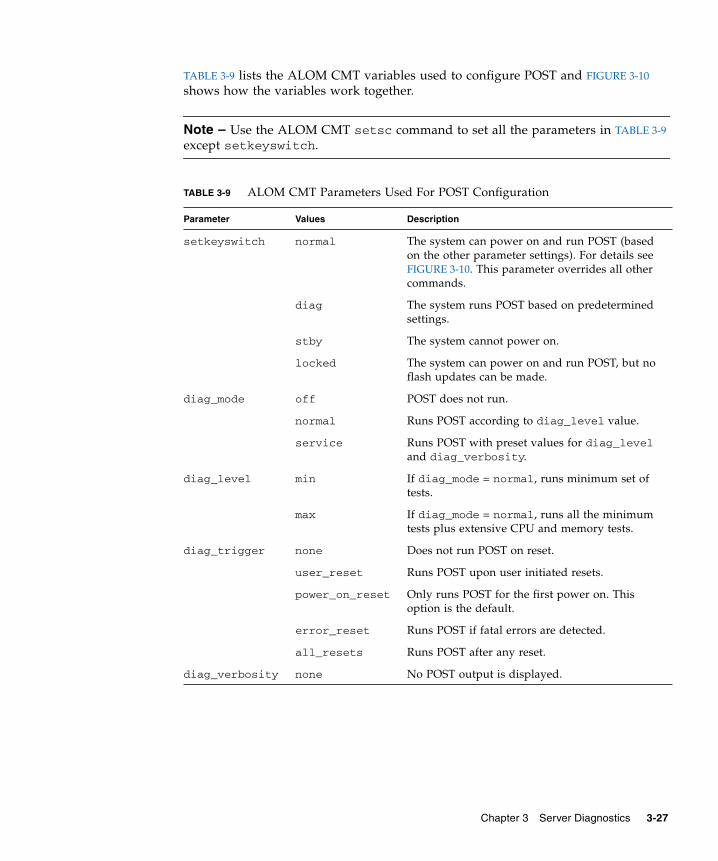
TABLE 3-9 lists the ALOM CMT variables used to configure POST and FIGURE 3-10shows how the variables work together.
Note – Use the ALOM CMT setsc command to set all the parameters in TABLE 3-9except setkeyswitch.
TABLE 3-9 ALOM CMT Parameters Used For POST Configuration
Parameter Values Description
setkeyswitch normal The system can power on and run POST (basedon the other parameter settings). For details seeFIGURE 3-10. This parameter overrides all othercommands.
diag The system runs POST based on predeterminedsettings.
stby The system cannot power on.
locked The system can power on and run POST, but noflash updates can be made.
diag_mode off POST does not run.
normal Runs POST according to diag_level value.
service Runs POST with preset values for diag_leveland diag_verbosity.
diag_level min If diag_mode = normal, runs minimum set oftests.
max If diag_mode = normal, runs all the minimumtests plus extensive CPU and memory tests.
diag_trigger none Does not run POST on reset.
user_reset Runs POST upon user initiated resets.
power_on_reset Only runs POST for the first power on. Thisoption is the default.
error_reset Runs POST if fatal errors are detected.
all_resets Runs POST after any reset.
diag_verbosity none No POST output is displayed.
Chapter 3 Server Diagnostics 3-27
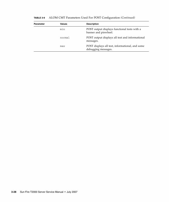
min POST output displays functional tests with abanner and pinwheel.
normal POST output displays all test and informationalmessages.
max POST displays all test, informational, and somedebugging messages.
TABLE 3-9 ALOM CMT Parameters Used For POST Configuration (Continued)
Parameter Values Description
3-28 Sun Fire T2000 Server Service Manual • July 2007
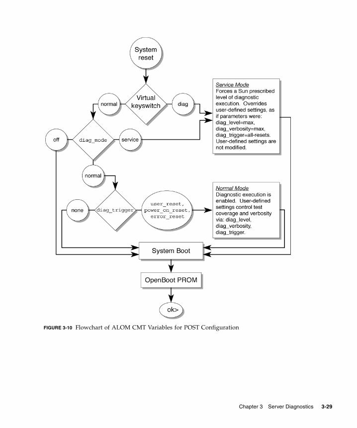
FIGURE 3-10 Flowchart of ALOM CMT Variables for POST Configuration
Chapter 3 Server Diagnostics 3-29
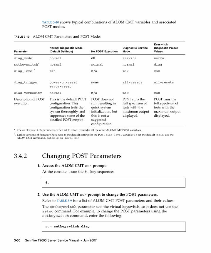
TABLE 3-10 shows typical combinations of ALOM CMT variables and associatedPOST modes.
3.4.2 Changing POST Parameters1. Access the ALOM CMT sc> prompt:
At the console, issue the #. key sequence:
2. Use the ALOM CMT sc> prompt to change the POST parameters.
Refer to TABLE 3-9 for a list of ALOM CMT POST parameters and their values.
The setkeyswitch parameter sets the virtual keyswitch, so it does not use thesetsc command. For example, to change the POST parameters using thesetkeyswitch command, enter the following:
TABLE 3-10 ALOM CMT Parameters and POST Modes
ParameterNormal Diagnostic Mode(Default Settings) No POST Execution
Diagnostic ServiceMode
KeyswitchDiagnostic PresetValues
diag_mode normal off service normal
setkeyswitch*
* The setkeyswitch parameter, when set to diag, overrides all the other ALOM CMT POST variables.
normal normal normal diag
diag_level\
\ Earlier versions of firmware have max as the default setting for the POST diag_level variable. To set the default to min, use theALOM CMT command, setsc diag_level min
min n/a max max
diag_trigger power-on-reseterror-reset
none all-resets all-resets
diag_verbosity normal n/a max max
Description of POSTexecution
This is the default POSTconfiguration. Thisconfiguration tests thesystem thoroughly, andsuppresses some of thedetailed POST output.
POST does notrun, resulting inquick systeminitialization, butthis is not asuggestedconfiguration.
POST runs thefull spectrum oftests with themaximum outputdisplayed.
POST runs thefull spectrum oftests with themaximum outputdisplayed.
#.
sc> setkeyswitch diag
3-30 Sun Fire T2000 Server Service Manual • July 2007
To change the POST parameters using the setsc command, you must first set thesetkeyswitch parameter to normal, then you can change the POST parametersusing the setsc command:
Example:
3.4.3 Reasons to Run POSTYou can use POST for basic hardware verification and diagnosis, and fortroubleshooting as described in the following sections.
3.4.3.1 Verifying Hardware Functionality
POST tests critical hardware components to verify functionality before the systemboots and accesses software. If POST detects an error, the faulty component isdisabled automatically, preventing faulty hardware from potentially harmingsoftware.
In normal operation (diag_level=min), POST runs in mimimum mode by defaultto test devices required to power on the server. Replace any devices POST detects asfaulty in minimum mode.
Run POST in maximum mode (diag_level=max) for all power-on or error-generated resets, and to validate hardware upgrades or repairs. With maximumtesting enabled, POST finds faults and offlines memory devices with errors thatcould be correctable by PSH. Check the POST-generated errors with theshowfaults -v command to verify if memory devices detected by POST can becorrected by PSH or need to be replaced. See Section 3.4.5, “Correctable ErrorsDetected by POST” on page 3-36.
sc> setkeyswitch normalsc> setsc value
sc> setkeyswitch normalsc> setsc diag_mode service
Chapter 3 Server Diagnostics 3-31
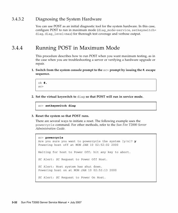
3.4.3.2 Diagnosing the System Hardware
You can use POST as an initial diagnostic tool for the system hardware. In this case,configure POST to run in maximum mode (diag_mode=service, setkeyswitch=diag, diag_level=max) for thorough test coverage and verbose output.
3.4.4 Running POST in Maximum ModeThis procedure describes how to run POST when you want maximum testing, as inthe case when you are troubleshooting a server or verifying a hardware upgrade orrepair.
1. Switch from the system console prompt to the sc> prompt by issuing the #. escapesequence.
2. Set the virtual keyswitch to diag so that POST will run in service mode.
3. Reset the system so that POST runs.
There are several ways to initiate a reset. The following example uses thepowercycle command. For other methods, refer to the Sun Fire T2000 ServerAdministration Guide.
ok #.sc>
sc> setkeyswitch diag
sc> powercycleAre you sure you want to powercycle the system [y/n]? yPowering host off at MON JAN 10 02:52:02 2000
Waiting for host to Power Off; hit any key to abort.
SC Alert: SC Request to Power Off Host.
SC Alert: Host system has shut down.Powering host on at MON JAN 10 02:52:13 2000
SC Alert: SC Request to Power On Host.
3-32 Sun Fire T2000 Server Service Manual • July 2007
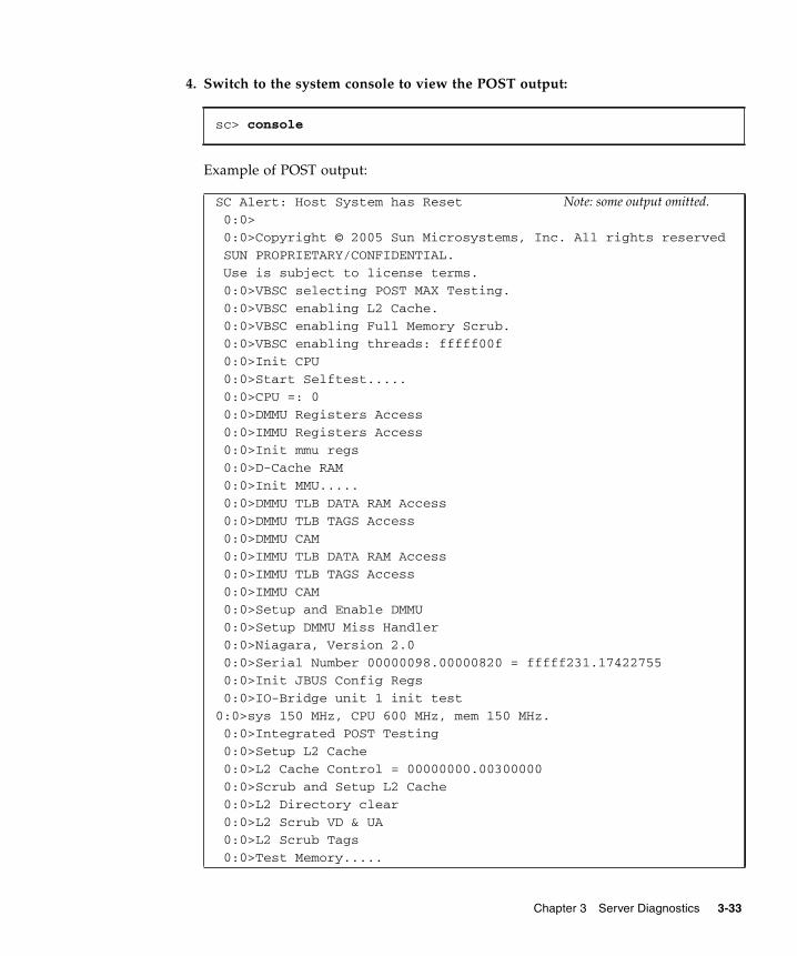
4. Switch to the system console to view the POST output:
Example of POST output:
sc> console
SC Alert: Host System has Reset Note: some output omitted. 0:0>
0:0>Copyright © 2005 Sun Microsystems, Inc. All rights reserved
SUN PROPRIETARY/CONFIDENTIAL.
Use is subject to license terms.
0:0>VBSC selecting POST MAX Testing.
0:0>VBSC enabling L2 Cache.
0:0>VBSC enabling Full Memory Scrub.
0:0>VBSC enabling threads: fffff00f
0:0>Init CPU
0:0>Start Selftest.....
0:0>CPU =: 0
0:0>DMMU Registers Access
0:0>IMMU Registers Access
0:0>Init mmu regs
0:0>D-Cache RAM
0:0>Init MMU.....
0:0>DMMU TLB DATA RAM Access
0:0>DMMU TLB TAGS Access
0:0>DMMU CAM
0:0>IMMU TLB DATA RAM Access
0:0>IMMU TLB TAGS Access
0:0>IMMU CAM
0:0>Setup and Enable DMMU
0:0>Setup DMMU Miss Handler
0:0>Niagara, Version 2.0
0:0>Serial Number 00000098.00000820 = fffff231.17422755
0:0>Init JBUS Config Regs
0:0>IO-Bridge unit 1 init test
0:0>sys 150 MHz, CPU 600 MHz, mem 150 MHz.
0:0>Integrated POST Testing
0:0>Setup L2 Cache
0:0>L2 Cache Control = 00000000.00300000
0:0>Scrub and Setup L2 Cache
0:0>L2 Directory clear
0:0>L2 Scrub VD & UA
0:0>L2 Scrub Tags
0:0>Test Memory.....
Chapter 3 Server Diagnostics 3-33
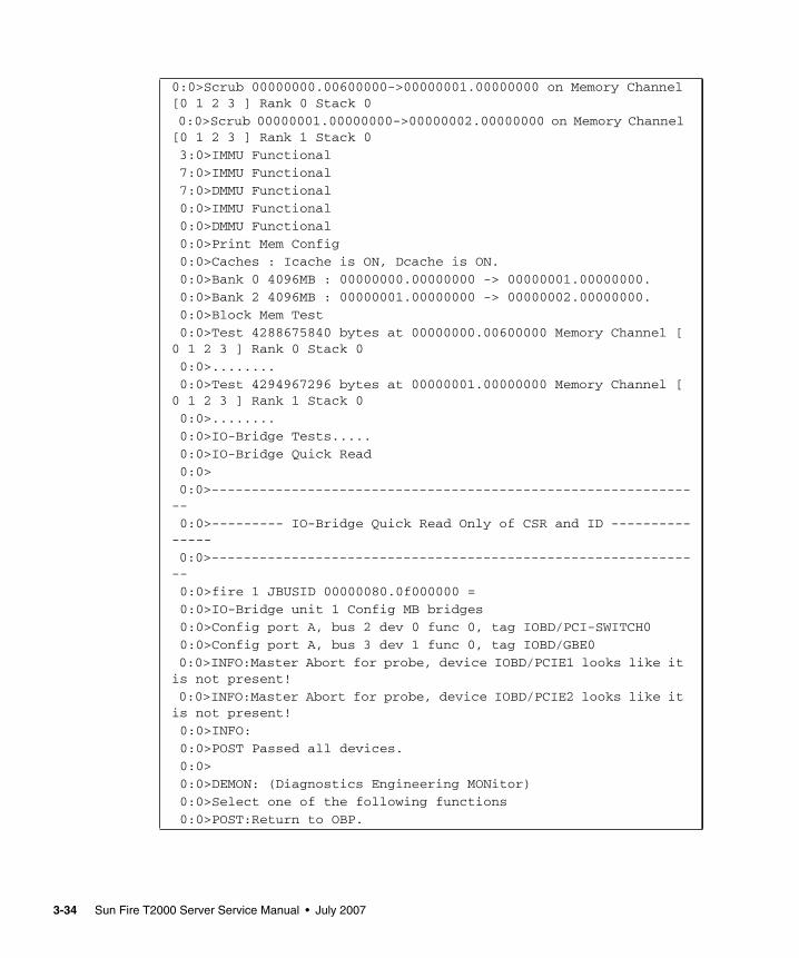
0:0>Scrub 00000000.00600000->00000001.00000000 on Memory Channel[0 1 2 3 ] Rank 0 Stack 0
0:0>Scrub 00000001.00000000->00000002.00000000 on Memory Channel[0 1 2 3 ] Rank 1 Stack 0
3:0>IMMU Functional
7:0>IMMU Functional
7:0>DMMU Functional
0:0>IMMU Functional
0:0>DMMU Functional
0:0>Print Mem Config
0:0>Caches : Icache is ON, Dcache is ON.
0:0>Bank 0 4096MB : 00000000.00000000 -> 00000001.00000000.
0:0>Bank 2 4096MB : 00000001.00000000 -> 00000002.00000000.
0:0>Block Mem Test
0:0>Test 4288675840 bytes at 00000000.00600000 Memory Channel [0 1 2 3 ] Rank 0 Stack 0
0:0>........
0:0>Test 4294967296 bytes at 00000001.00000000 Memory Channel [0 1 2 3 ] Rank 1 Stack 0
0:0>........
0:0>IO-Bridge Tests.....
0:0>IO-Bridge Quick Read
0:0>
0:0>--------------------------------------------------------------
0:0>--------- IO-Bridge Quick Read Only of CSR and ID ---------------
0:0>--------------------------------------------------------------
0:0>fire 1 JBUSID 00000080.0f000000 =
0:0>IO-Bridge unit 1 Config MB bridges
0:0>Config port A, bus 2 dev 0 func 0, tag IOBD/PCI-SWITCH0
0:0>Config port A, bus 3 dev 1 func 0, tag IOBD/GBE0
0:0>INFO:Master Abort for probe, device IOBD/PCIE1 looks like itis not present!
0:0>INFO:Master Abort for probe, device IOBD/PCIE2 looks like itis not present!
0:0>INFO:
0:0>POST Passed all devices.
0:0>
0:0>DEMON: (Diagnostics Engineering MONitor)
0:0>Select one of the following functions
0:0>POST:Return to OBP.
3-34 Sun Fire T2000 Server Service Manual • July 2007
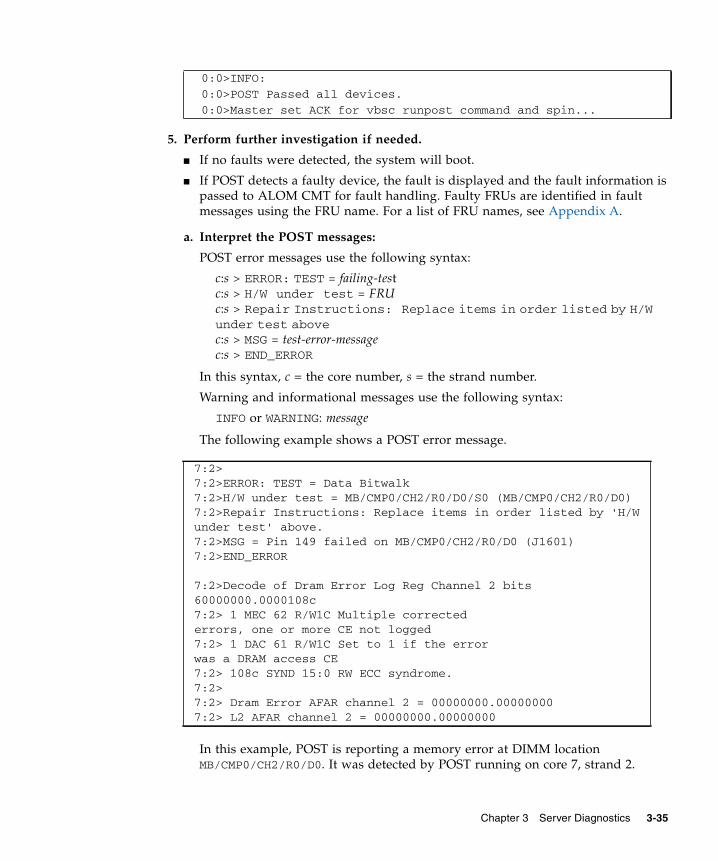
5. Perform further investigation if needed.
■ If no faults were detected, the system will boot.
■ If POST detects a faulty device, the fault is displayed and the fault information ispassed to ALOM CMT for fault handling. Faulty FRUs are identified in faultmessages using the FRU name. For a list of FRU names, see Appendix A.
a. Interpret the POST messages:
POST error messages use the following syntax:
c:s > ERROR: TEST = failing-testc:s > H/W under test = FRUc:s > Repair Instructions: Replace items in order listed by H/Wunder test abovec:s > MSG = test-error-messagec:s > END_ERROR
In this syntax, c = the core number, s = the strand number.
Warning and informational messages use the following syntax:
INFO or WARNING: message
The following example shows a POST error message.
In this example, POST is reporting a memory error at DIMM locationMB/CMP0/CH2/R0/D0. It was detected by POST running on core 7, strand 2.
0:0>INFO:
0:0>POST Passed all devices.
0:0>Master set ACK for vbsc runpost command and spin...
7:2>7:2>ERROR: TEST = Data Bitwalk7:2>H/W under test = MB/CMP0/CH2/R0/D0/S0 (MB/CMP0/CH2/R0/D0)7:2>Repair Instructions: Replace items in order listed by 'H/Wunder test' above.7:2>MSG = Pin 149 failed on MB/CMP0/CH2/R0/D0 (J1601)7:2>END_ERROR
7:2>Decode of Dram Error Log Reg Channel 2 bits60000000.0000108c7:2> 1 MEC 62 R/W1C Multiple correctederrors, one or more CE not logged7:2> 1 DAC 61 R/W1C Set to 1 if the errorwas a DRAM access CE7:2> 108c SYND 15:0 RW ECC syndrome.7:2>7:2> Dram Error AFAR channel 2 = 00000000.000000007:2> L2 AFAR channel 2 = 00000000.00000000
Chapter 3 Server Diagnostics 3-35
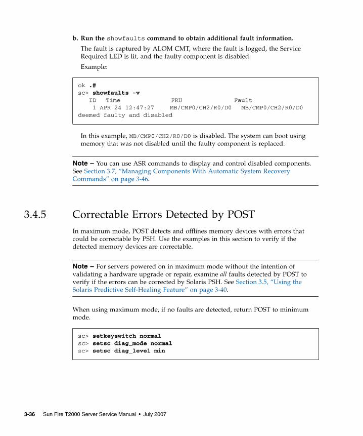
b. Run the showfaults command to obtain additional fault information.
The fault is captured by ALOM CMT, where the fault is logged, the ServiceRequired LED is lit, and the faulty component is disabled.
Example:
In this example, MB/CMP0/CH2/R0/D0 is disabled. The system can boot usingmemory that was not disabled until the faulty component is replaced.
Note – You can use ASR commands to display and control disabled components.See Section 3.7, “Managing Components With Automatic System RecoveryCommands” on page 3-46.
3.4.5 Correctable Errors Detected by POSTIn maximum mode, POST detects and offlines memory devices with errors thatcould be correctable by PSH. Use the examples in this section to verify if thedetected memory devices are correctable.
Note – For servers powered on in maximum mode without the intention ofvalidating a hardware upgrade or repair, examine all faults detected by POST toverify if the errors can be corrected by Solaris PSH. See Section 3.5, “Using theSolaris Predictive Self-Healing Feature” on page 3-40.
When using maximum mode, if no faults are detected, return POST to minimummode.
ok .#sc> showfaults -v ID Time FRU Fault 1 APR 24 12:47:27 MB/CMP0/CH2/R0/D0 MB/CMP0/CH2/R0/D0deemed faulty and disabled
sc> setkeyswitch normalsc> setsc diag_mode normalsc> setsc diag_level min
3-36 Sun Fire T2000 Server Service Manual • July 2007
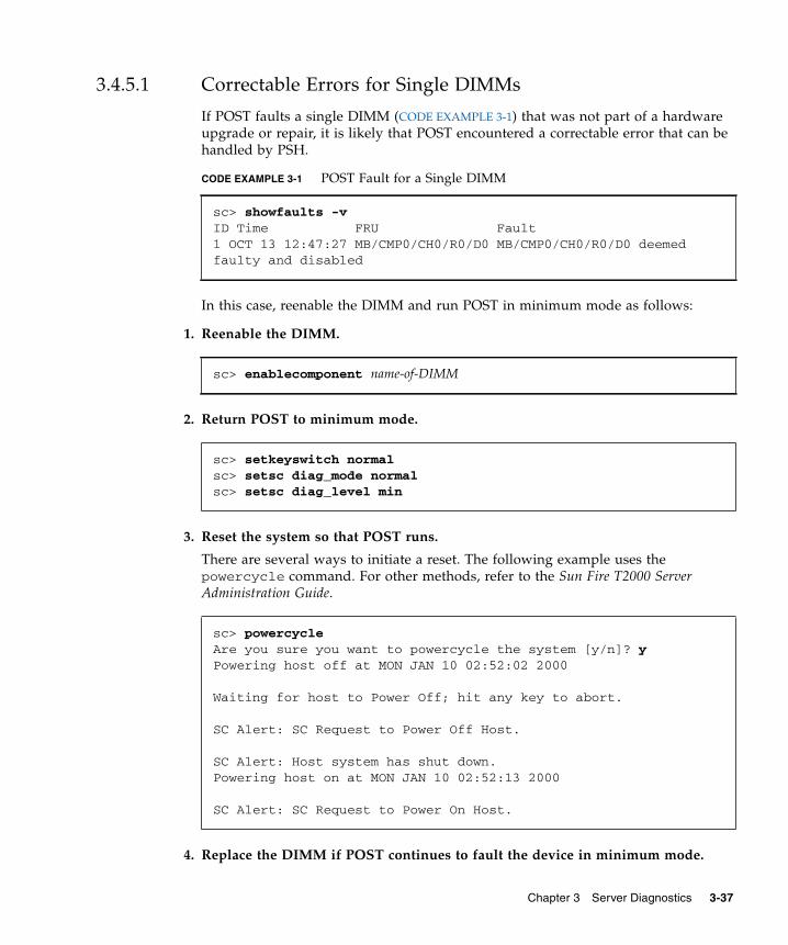
3.4.5.1 Correctable Errors for Single DIMMs
If POST faults a single DIMM (CODE EXAMPLE 3-1) that was not part of a hardwareupgrade or repair, it is likely that POST encountered a correctable error that can behandled by PSH.
In this case, reenable the DIMM and run POST in minimum mode as follows:
1. Reenable the DIMM.
2. Return POST to minimum mode.
3. Reset the system so that POST runs.
There are several ways to initiate a reset. The following example uses thepowercycle command. For other methods, refer to the Sun Fire T2000 ServerAdministration Guide.
4. Replace the DIMM if POST continues to fault the device in minimum mode.
CODE EXAMPLE 3-1 POST Fault for a Single DIMM
sc> showfaults -vID Time FRU Fault1 OCT 13 12:47:27 MB/CMP0/CH0/R0/D0 MB/CMP0/CH0/R0/D0 deemedfaulty and disabled
sc> enablecomponent name-of-DIMM
sc> setkeyswitch normalsc> setsc diag_mode normalsc> setsc diag_level min
sc> powercycleAre you sure you want to powercycle the system [y/n]? yPowering host off at MON JAN 10 02:52:02 2000
Waiting for host to Power Off; hit any key to abort.
SC Alert: SC Request to Power Off Host.
SC Alert: Host system has shut down.Powering host on at MON JAN 10 02:52:13 2000
SC Alert: SC Request to Power On Host.
Chapter 3 Server Diagnostics 3-37
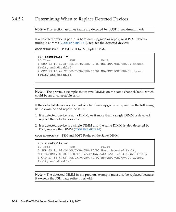
3.4.5.2 Determining When to Replace Detected Devices
Note – This section assumes faults are detected by POST in maximum mode.
If a detected device is part of a hardware upgrade or repair, or if POST detectsmultiple DIMMs (CODE EXAMPLE 3-2), replace the detected devices.
Note – The previous example shows two DIMMs on the same channel/rank, whichcould be an uncorrectable error.
If the detected device is not a part of a hardware upgrade or repair, use the followinglist to examine and repair the fault:
1. If a detected device is not a DIMM, or if more than a single DIMM is detected,replace the detected devices.
2. If a detected device is a single DIMM and the same DIMM is also detected byPSH, replace the DIMM (CODE EXAMPLE 3-3).
Note – The detected DIMM in the previous example must also be replaced becauseit exceeds the PSH page retire threshold.
CODE EXAMPLE 3-2 POST Fault for Multiple DIMMs
sc> showfaults -vID Time FRU Fault1 OCT 13 12:47:27 MB/CMP0/CH0/R0/D0 MB/CMP0/CH0/R0/D0 deemedfaulty and disabled2 OCT 13 12:47:27 MB/CMP0/CH0/R0/D1 MB/CMP0/CH0/R0/D1 deemedfaulty and disabled
CODE EXAMPLE 3-3 PSH and POST Faults on the Same DIMM
sc> showfaults -vID Time FRU Fault0 SEP 09 11:09:26 MB/CMP0/CH0/R0/D0 Host detected fault,MSGID:SUN4V-8000-DX UUID: 7ee0e46b-ea64-6565-e684-e996963f7b861 OCT 13 12:47:27 MB/CMP0/CH0/R0/D0 MB/CMP0/CH0/R0/D0 deemedfaulty and disabled
3-38 Sun Fire T2000 Server Service Manual • July 2007
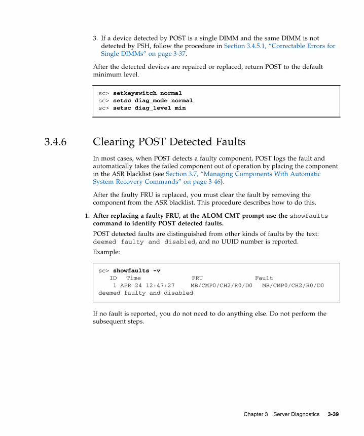
3. If a device detected by POST is a single DIMM and the same DIMM is notdetected by PSH, follow the procedure in Section 3.4.5.1, “Correctable Errors forSingle DIMMs” on page 3-37.
After the detected devices are repaired or replaced, return POST to the defaultminimum level.
3.4.6 Clearing POST Detected FaultsIn most cases, when POST detects a faulty component, POST logs the fault andautomatically takes the failed component out of operation by placing the componentin the ASR blacklist (see Section 3.7, “Managing Components With AutomaticSystem Recovery Commands” on page 3-46).
After the faulty FRU is replaced, you must clear the fault by removing thecomponent from the ASR blacklist. This procedure describes how to do this.
1. After replacing a faulty FRU, at the ALOM CMT prompt use the showfaultscommand to identify POST detected faults.
POST detected faults are distinguished from other kinds of faults by the text:deemed faulty and disabled, and no UUID number is reported.
Example:
If no fault is reported, you do not need to do anything else. Do not perform thesubsequent steps.
sc> setkeyswitch normalsc> setsc diag_mode normalsc> setsc diag_level min
sc> showfaults -v ID Time FRU Fault 1 APR 24 12:47:27 MB/CMP0/CH2/R0/D0 MB/CMP0/CH2/R0/D0deemed faulty and disabled
Chapter 3 Server Diagnostics 3-39
2. Use the enablecomponent command to clear the fault and remove the componentfrom the ASR blacklist.
Use the FRU name that was reported in the fault in the previous step.
Example:
The fault is cleared and should not show up when you run the showfaultscommand. Additionally, the Service Required LED is no longer on.
3. Power cycle the server.
You must reboot the server for the enablecomponent command to take effect.
4. At the ALOM CMT prompt, use the showfaults command to verify that nofaults are reported.
3.5 Using the Solaris Predictive Self-HealingFeatureThe Solaris Predictive Self-Healing (PSH) technology enables the server to diagnoseproblems while the Solaris OS is running, and mitigate many problems before theynegatively affect operations.
The Solaris OS uses the fault manager daemon, fmd(1M), which starts at boot timeand runs in the background to monitor the system. If a component generates anerror, the daemon handles the error by correlating the error with data from previouserrors and other related information to diagnose the problem. Once diagnosed, thefault manager daemon assigns the problem a Universal Unique Identifier (UUID)that distinguishes the problem across any set of systems. When possible, the faultmanager daemon initiates steps to self-heal the failed component and take thecomponent offline. The daemon also logs the fault to the syslogd daemon andprovides a fault notification with a message ID (MSGID). You can use the messageID to get additional information about the problem from Sun’s knowledge articledatabase.
sc> enablecomponent MB/CMP0/CH0/R0/D0
sc> showfaultsLast POST run: THU MAR 09 16:52:44 2006POST status: Passed all devices
No failures found in System
3-40 Sun Fire T2000 Server Service Manual • July 2007
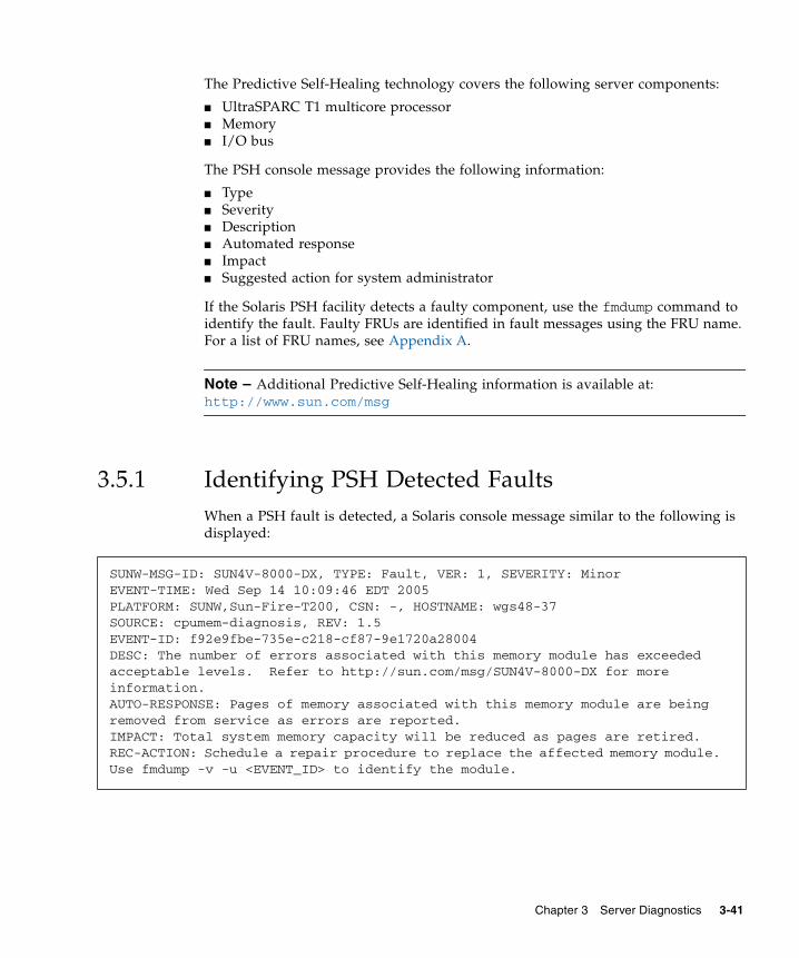
The Predictive Self-Healing technology covers the following server components:
■ UltraSPARC T1 multicore processor■ Memory■ I/O bus
The PSH console message provides the following information:
■ Type■ Severity■ Description■ Automated response■ Impact■ Suggested action for system administrator
If the Solaris PSH facility detects a faulty component, use the fmdump command toidentify the fault. Faulty FRUs are identified in fault messages using the FRU name.For a list of FRU names, see Appendix A.
Note – Additional Predictive Self-Healing information is available at:http://www.sun.com/msg
3.5.1 Identifying PSH Detected FaultsWhen a PSH fault is detected, a Solaris console message similar to the following isdisplayed:
SUNW-MSG-ID: SUN4V-8000-DX, TYPE: Fault, VER: 1, SEVERITY: MinorEVENT-TIME: Wed Sep 14 10:09:46 EDT 2005PLATFORM: SUNW,Sun-Fire-T200, CSN: -, HOSTNAME: wgs48-37SOURCE: cpumem-diagnosis, REV: 1.5EVENT-ID: f92e9fbe-735e-c218-cf87-9e1720a28004DESC: The number of errors associated with this memory module has exceededacceptable levels. Refer to http://sun.com/msg/SUN4V-8000-DX for moreinformation.AUTO-RESPONSE: Pages of memory associated with this memory module are beingremoved from service as errors are reported.IMPACT: Total system memory capacity will be reduced as pages are retired.REC-ACTION: Schedule a repair procedure to replace the affected memory module.Use fmdump -v -u <EVENT_ID> to identify the module.
Chapter 3 Server Diagnostics 3-41
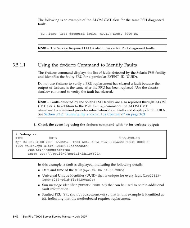
The following is an example of the ALOM CMT alert for the same PSH diagnosedfault:
Note – The Service Required LED is also turns on for PSH diagnosed faults.
3.5.1.1 Using the fmdump Command to Identify Faults
The fmdump command displays the list of faults detected by the Solaris PSH facilityand identifies the faulty FRU for a particular EVENT_ID (UUID).
Do not use fmdump to verify a FRU replacement has cleared a fault because theoutput of fmdump is the same after the FRU has been replaced. Use the fmadmfaulty command to verify the fault has cleared.
Note – Faults detected by the Solaris PSH facility are also reported through ALOMCMT alerts. In addition to the PSH fmdump command, the ALOM CMTshowfaults command provides information about faults and displays fault UUIDs.See Section 3.3.2, “Running the showfaults Command” on page 3-21.
1. Check the event log using the fmdump command with -v for verbose output:
In this example, a fault is displayed, indicating the following details:
■ Date and time of the fault (Apr 24 06:54:08.2005)
■ Universal Unique Identifier (UUID) that is unique for every fault (lce22523-lc80-6062-e61d-f3b39290ae2c)
■ Sun message identifier (SUNW4V-8000-6H) that can be used to obtain additionalfault information
■ Faulted FRU (FRU:hc:///component=MB), that in this example is identified asMB, indicating that the motherboard requires replacement.
SC Alert: Host detected fault, MSGID: SUN4V-8000-DX
# fmdump -vTIME UUID SUNW-MSG-IDApr 24 06:54:08.2005 lce22523-lc80-6062-e61d-f3b39290ae2c SUN4U-8000-6H100% fault.cpu.ultraSPARCT1l2cachedata
FRU:hc:///component=MBrsrc: cpu:///cpuid=0/serial=22D1D6604A
3-42 Sun Fire T2000 Server Service Manual • July 2007
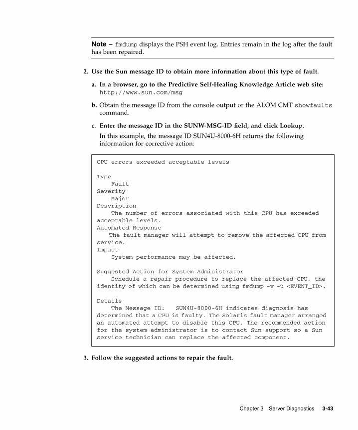
Note – fmdump displays the PSH event log. Entries remain in the log after the faulthas been repaired.
2. Use the Sun message ID to obtain more information about this type of fault.
a. In a browser, go to the Predictive Self-Healing Knowledge Article web site:http://www.sun.com/msg
b. Obtain the message ID from the console output or the ALOM CMT showfaultscommand.
c. Enter the message ID in the SUNW-MSG-ID field, and click Lookup.
In this example, the message ID SUN4U-8000-6H returns the followinginformation for corrective action:
3. Follow the suggested actions to repair the fault.
CPU errors exceeded acceptable levels
Type FaultSeverity MajorDescription The number of errors associated with this CPU has exceededacceptable levels.Automated Response
The fault manager will attempt to remove the affected CPU fromservice.Impact System performance may be affected.
Suggested Action for System AdministratorSchedule a repair procedure to replace the affected CPU, the
identity of which can be determined using fmdump -v -u <EVENT_ID>.
Details The Message ID: SUN4U-8000-6H indicates diagnosis hasdetermined that a CPU is faulty. The Solaris fault manager arrangedan automated attempt to disable this CPU. The recommended actionfor the system administrator is to contact Sun support so a Sunservice technician can replace the affected component.
Chapter 3 Server Diagnostics 3-43
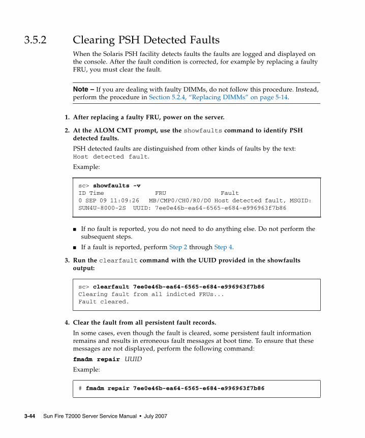
3.5.2 Clearing PSH Detected FaultsWhen the Solaris PSH facility detects faults the faults are logged and displayed onthe console. After the fault condition is corrected, for example by replacing a faultyFRU, you must clear the fault.
Note – If you are dealing with faulty DIMMs, do not follow this procedure. Instead,perform the procedure in Section 5.2.4, “Replacing DIMMs” on page 5-14.
1. After replacing a faulty FRU, power on the server.
2. At the ALOM CMT prompt, use the showfaults command to identify PSHdetected faults.
PSH detected faults are distinguished from other kinds of faults by the text:Host detected fault.
Example:
■ If no fault is reported, you do not need to do anything else. Do not perform thesubsequent steps.
■ If a fault is reported, perform Step 2 through Step 4.
3. Run the clearfault command with the UUID provided in the showfaultsoutput:
4. Clear the fault from all persistent fault records.
In some cases, even though the fault is cleared, some persistent fault informationremains and results in erroneous fault messages at boot time. To ensure that thesemessages are not displayed, perform the following command:
fmadm repair UUID
Example:
sc> showfaults -vID Time FRU Fault0 SEP 09 11:09:26 MB/CMP0/CH0/R0/D0 Host detected fault, MSGID:SUN4U-8000-2S UUID: 7ee0e46b-ea64-6565-e684-e996963f7b86
sc> clearfault 7ee0e46b-ea64-6565-e684-e996963f7b86Clearing fault from all indicted FRUs...Fault cleared.
# fmadm repair 7ee0e46b-ea64-6565-e684-e996963f7b86
3-44 Sun Fire T2000 Server Service Manual • July 2007
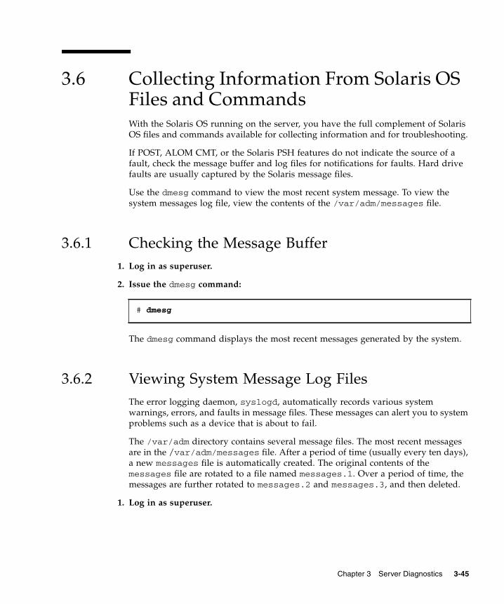
3.6 Collecting Information From Solaris OSFiles and CommandsWith the Solaris OS running on the server, you have the full complement of SolarisOS files and commands available for collecting information and for troubleshooting.
If POST, ALOM CMT, or the Solaris PSH features do not indicate the source of afault, check the message buffer and log files for notifications for faults. Hard drivefaults are usually captured by the Solaris message files.
Use the dmesg command to view the most recent system message. To view thesystem messages log file, view the contents of the /var/adm/messages file.
3.6.1 Checking the Message Buffer1. Log in as superuser.
2. Issue the dmesg command:
The dmesg command displays the most recent messages generated by the system.
3.6.2 Viewing System Message Log FilesThe error logging daemon, syslogd, automatically records various systemwarnings, errors, and faults in message files. These messages can alert you to systemproblems such as a device that is about to fail.
The /var/adm directory contains several message files. The most recent messagesare in the /var/adm/messages file. After a period of time (usually every ten days),a new messages file is automatically created. The original contents of themessages file are rotated to a file named messages.1. Over a period of time, themessages are further rotated to messages.2 and messages.3, and then deleted.
1. Log in as superuser.
# dmesg
Chapter 3 Server Diagnostics 3-45
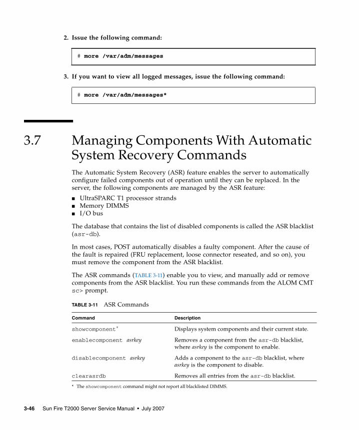
2. Issue the following command:
3. If you want to view all logged messages, issue the following command:
3.7 Managing Components With AutomaticSystem Recovery CommandsThe Automatic System Recovery (ASR) feature enables the server to automaticallyconfigure failed components out of operation until they can be replaced. In theserver, the following components are managed by the ASR feature:
■ UltraSPARC T1 processor strands■ Memory DIMMS■ I/O bus
The database that contains the list of disabled components is called the ASR blacklist(asr-db).
In most cases, POST automatically disables a faulty component. After the cause ofthe fault is repaired (FRU replacement, loose connector reseated, and so on), youmust remove the component from the ASR blacklist.
The ASR commands (TABLE 3-11) enable you to view, and manually add or removecomponents from the ASR blacklist. You run these commands from the ALOM CMTsc> prompt.
# more /var/adm/messages
# more /var/adm/messages*
TABLE 3-11 ASR Commands
Command Description
showcomponent*
* The showcomponent command might not report all blacklisted DIMMS.
Displays system components and their current state.
enablecomponent asrkey Removes a component from the asr-db blacklist,where asrkey is the component to enable.
disablecomponent asrkey Adds a component to the asr-db blacklist, whereasrkey is the component to disable.
clearasrdb Removes all entries from the asr-db blacklist.
3-46 Sun Fire T2000 Server Service Manual • July 2007
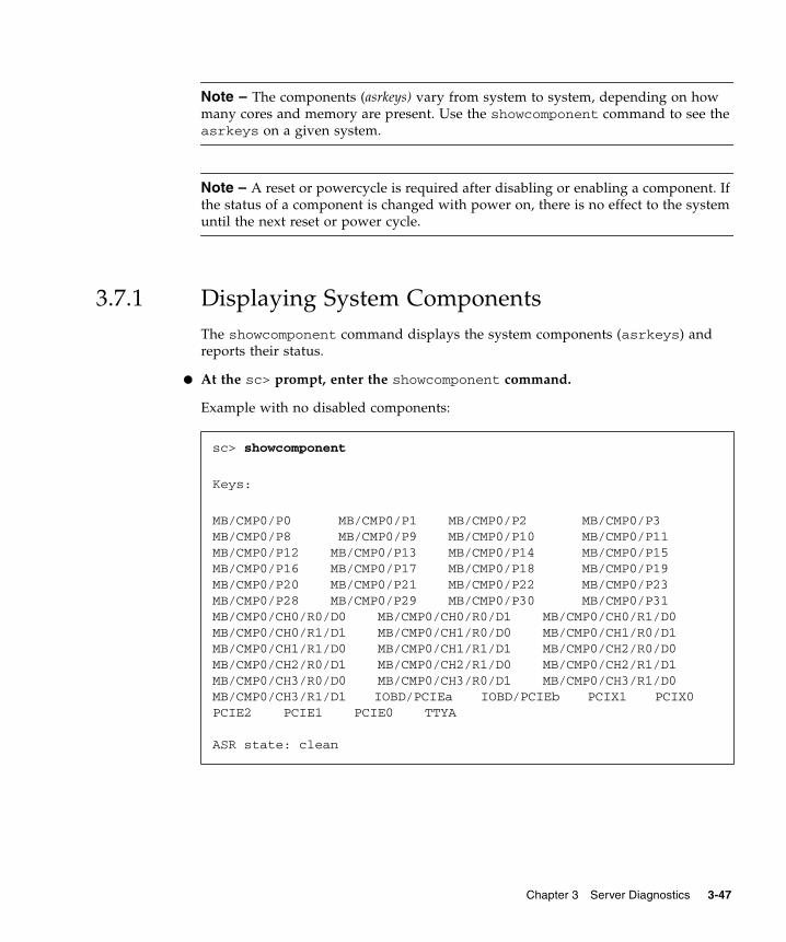
Note – The components (asrkeys) vary from system to system, depending on howmany cores and memory are present. Use the showcomponent command to see theasrkeys on a given system.
Note – A reset or powercycle is required after disabling or enabling a component. Ifthe status of a component is changed with power on, there is no effect to the systemuntil the next reset or power cycle.
3.7.1 Displaying System ComponentsThe showcomponent command displays the system components (asrkeys) andreports their status.
● At the sc> prompt, enter the showcomponent command.
Example with no disabled components:
sc> showcomponent
Keys:
MB/CMP0/P0 MB/CMP0/P1 MB/CMP0/P2 MB/CMP0/P3MB/CMP0/P8 MB/CMP0/P9 MB/CMP0/P10 MB/CMP0/P11MB/CMP0/P12 MB/CMP0/P13 MB/CMP0/P14 MB/CMP0/P15MB/CMP0/P16 MB/CMP0/P17 MB/CMP0/P18 MB/CMP0/P19MB/CMP0/P20 MB/CMP0/P21 MB/CMP0/P22 MB/CMP0/P23MB/CMP0/P28 MB/CMP0/P29 MB/CMP0/P30 MB/CMP0/P31MB/CMP0/CH0/R0/D0 MB/CMP0/CH0/R0/D1 MB/CMP0/CH0/R1/D0MB/CMP0/CH0/R1/D1 MB/CMP0/CH1/R0/D0 MB/CMP0/CH1/R0/D1MB/CMP0/CH1/R1/D0 MB/CMP0/CH1/R1/D1 MB/CMP0/CH2/R0/D0MB/CMP0/CH2/R0/D1 MB/CMP0/CH2/R1/D0 MB/CMP0/CH2/R1/D1MB/CMP0/CH3/R0/D0 MB/CMP0/CH3/R0/D1 MB/CMP0/CH3/R1/D0MB/CMP0/CH3/R1/D1 IOBD/PCIEa IOBD/PCIEb PCIX1 PCIX0PCIE2 PCIE1 PCIE0 TTYA
ASR state: clean
Chapter 3 Server Diagnostics 3-47
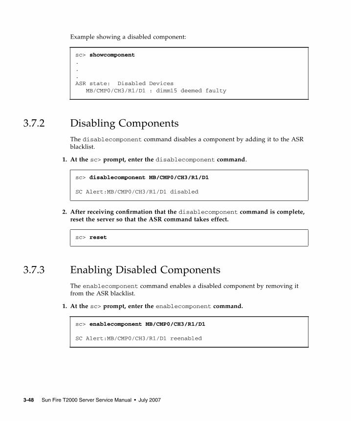
Example showing a disabled component:
3.7.2 Disabling ComponentsThe disablecomponent command disables a component by adding it to the ASRblacklist.
1. At the sc> prompt, enter the disablecomponent command.
2. After receiving confirmation that the disablecomponent command is complete,reset the server so that the ASR command takes effect.
3.7.3 Enabling Disabled ComponentsThe enablecomponent command enables a disabled component by removing itfrom the ASR blacklist.
1. At the sc> prompt, enter the enablecomponent command.
sc> showcomponent...ASR state: Disabled Devices MB/CMP0/CH3/R1/D1 : dimm15 deemed faulty
sc> disablecomponent MB/CMP0/CH3/R1/D1
SC Alert:MB/CMP0/CH3/R1/D1 disabled
sc> reset
sc> enablecomponent MB/CMP0/CH3/R1/D1
SC Alert:MB/CMP0/CH3/R1/D1 reenabled
3-48 Sun Fire T2000 Server Service Manual • July 2007
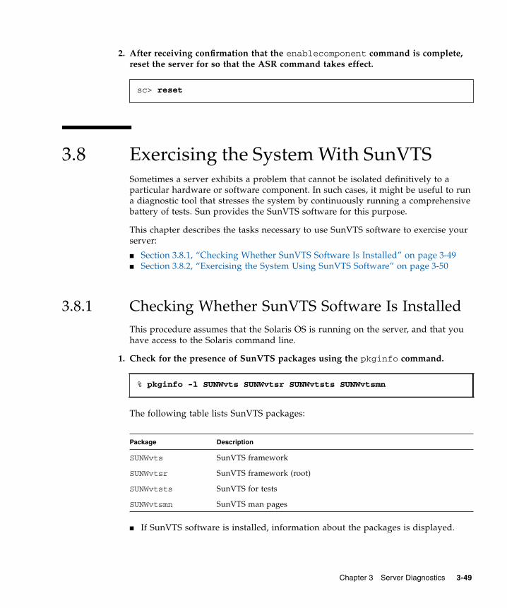
2. After receiving confirmation that the enablecomponent command is complete,reset the server for so that the ASR command takes effect.
3.8 Exercising the System With SunVTSSometimes a server exhibits a problem that cannot be isolated definitively to aparticular hardware or software component. In such cases, it might be useful to runa diagnostic tool that stresses the system by continuously running a comprehensivebattery of tests. Sun provides the SunVTS software for this purpose.
This chapter describes the tasks necessary to use SunVTS software to exercise yourserver:
■ Section 3.8.1, “Checking Whether SunVTS Software Is Installed” on page 3-49■ Section 3.8.2, “Exercising the System Using SunVTS Software” on page 3-50
3.8.1 Checking Whether SunVTS Software Is InstalledThis procedure assumes that the Solaris OS is running on the server, and that youhave access to the Solaris command line.
1. Check for the presence of SunVTS packages using the pkginfo command.
The following table lists SunVTS packages:
■ If SunVTS software is installed, information about the packages is displayed.
sc> reset
% pkginfo -l SUNWvts SUNWvtsr SUNWvtsts SUNWvtsmn
Package Description
SUNWvts SunVTS framework
SUNWvtsr SunVTS framework (root)
SUNWvtsts SunVTS for tests
SUNWvtsmn SunVTS man pages
Chapter 3 Server Diagnostics 3-49
■ If SunVTS software is not installed, you see an error message for each missingpackage.
If SunVTS is not installed, you can obtain the installation packages from thefollowing places:
■ Solaris Operating System DVDs■ From the Sun Download Center: http://www.sun.com/oem/products/vts
The SunVTS 6.0 PS3 software, and future compatible versions, are supported on theserver.
SunVTS installation instructions are described in the SunVTS User’s Guide.
3.8.2 Exercising the System Using SunVTS SoftwareBefore you begin, the Solaris OS must be running. You also need to ensure thatSunVTS validation test software is installed on your system. See Section 3.8.1,“Checking Whether SunVTS Software Is Installed” on page 3-49.
The SunVTS installation process requires that you specify one of two securityschemes to use when running SunVTS. The security scheme you choose must beproperly configured in the Solaris OS for you to run SunVTS. For details, refer to theSunVTS User’s Guide.
SunVTS software features both character-based and graphics-based interfaces. Thisprocedure assumes that you are using the graphical user interface (GUI) on a systemrunning the Common Desktop Environment (CDE). For more information about thecharacter-based SunVTS TTY interface, and specifically for instructions on accessingit by tip or telnet commands, refer to the SunVTS User’s Guide.
SunVTS software can be run in several modes. This procedure assumes that you areusing the default mode.
This procedure also assumes that the server is headless. That is, it is not equippedwith a monitor capable of displaying bitmap graphics. In this case, you access theSunVTS GUI by logging in remotely from a machine that has a graphics display.
Finally, this procedure describes how to run SunVTS tests in general. Individual testsmight presume the presence of specific hardware, or might require specific drivers,cables, or loopback connectors. For information about test options and prerequisites,refer to the following documentation:
ERROR: information for "SUNWvts" was not foundERROR: information for "SUNWvtsr" was not found...
3-50 Sun Fire T2000 Server Service Manual • July 2007
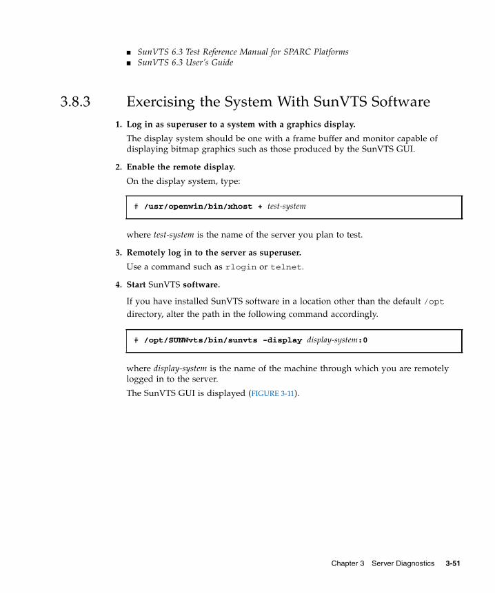
■ SunVTS 6.3 Test Reference Manual for SPARC Platforms■ SunVTS 6.3 User’s Guide
3.8.3 Exercising the System With SunVTS Software1. Log in as superuser to a system with a graphics display.
The display system should be one with a frame buffer and monitor capable ofdisplaying bitmap graphics such as those produced by the SunVTS GUI.
2. Enable the remote display.
On the display system, type:
where test-system is the name of the server you plan to test.
3. Remotely log in to the server as superuser.
Use a command such as rlogin or telnet.
4. Start SunVTS software.
If you have installed SunVTS software in a location other than the default /optdirectory, alter the path in the following command accordingly.
where display-system is the name of the machine through which you are remotelylogged in to the server.
The SunVTS GUI is displayed (FIGURE 3-11).
# /usr/openwin/bin/xhost + test-system
# /opt/SUNWvts/bin/sunvts -display display-system:0
Chapter 3 Server Diagnostics 3-51
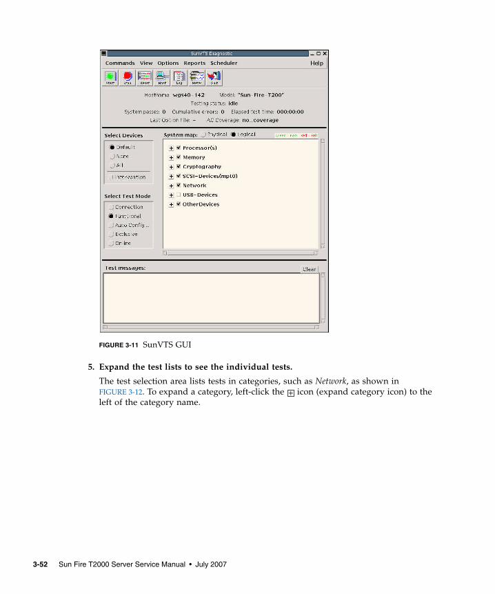
FIGURE 3-11 SunVTS GUI
5. Expand the test lists to see the individual tests.
The test selection area lists tests in categories, such as Network, as shown inFIGURE 3-12. To expand a category, left-click the icon (expand category icon) to theleft of the category name.
+
3-52 Sun Fire T2000 Server Service Manual • July 2007
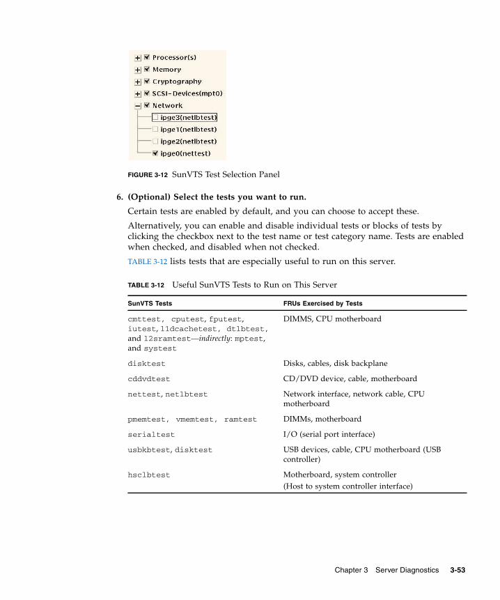
FIGURE 3-12 SunVTS Test Selection Panel
6. (Optional) Select the tests you want to run.
Certain tests are enabled by default, and you can choose to accept these.
Alternatively, you can enable and disable individual tests or blocks of tests byclicking the checkbox next to the test name or test category name. Tests are enabledwhen checked, and disabled when not checked.
TABLE 3-12 lists tests that are especially useful to run on this server.
TABLE 3-12 Useful SunVTS Tests to Run on This Server
SunVTS Tests FRUs Exercised by Tests
cmttest, cputest, fputest,iutest, l1dcachetest, dtlbtest,and l2sramtest—indirectly: mptest,and systest
DIMMS, CPU motherboard
disktest Disks, cables, disk backplane
cddvdtest CD/DVD device, cable, motherboard
nettest, netlbtest Network interface, network cable, CPUmotherboard
pmemtest, vmemtest, ramtest DIMMs, motherboard
serialtest I/O (serial port interface)
usbkbtest, disktest USB devices, cable, CPU motherboard (USBcontroller)
hsclbtest Motherboard, system controller(Host to system controller interface)
Chapter 3 Server Diagnostics 3-53
7. (Optional) Customize individual tests.
You can customize individual tests by right-clicking on the name of the test. Forexample, in FIGURE 3-12, right-clicking on the text string ce0(nettest) brings up amenu that enables you to configure this Ethernet test.
8. Start testing.
Click the Start button that is located at the top left of the SunVTS window. Statusand error messages appear in the test messages area located across the bottom of thewindow. You can stop testing at any time by clicking the Stop button.
During testing, SunVTS software logs all status and error messages. To view thesemessages, click the Log button or select Log Files from the Reports menu. This actionopens a log window from which you can choose to view the following logs:
■ Information – Detailed versions of all the status and error messages that appearin the test messages area.
■ Test Error – Detailed error messages from individual tests.
■ VTS Kernel Error – Error messages pertaining to SunVTS software itself. Lookhere if SunVTS software appears to be acting strangely, especially when it startsup.
■ Solaris OS Messages (/var/adm/messages) – A file containing messagesgenerated by the operating system and various applications.
■ Log Files (/var/opt/SUNWvts/logs) – A directory containing the log files.
3-54 Sun Fire T2000 Server Service Manual • July 2007
CHAPTER 4
Replacing Hot-Swappable and Hot-Pluggable FRUs
This chapter describes how to remove and replace the hot-swappable and hot-pluggable field-replaceable units (FRUs) in the server.
The following topics are covered:
■ Section 4.1, “Devices That Are Hot-Swappable and Hot-Pluggable” on page 4-2■ Section 4.2, “Hot-Swapping a Fan” on page 4-2■ Section 4.3, “Hot-Swapping a Power Supply” on page 4-4■ Section 4.4, “Hot-Swapping the Rear Blower” on page 4-7■ Section 4.5, “Hot-Plugging a Hard Drive” on page 4-9
4-1
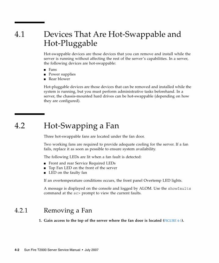
4.1 Devices That Are Hot-Swappable andHot-PluggableHot-swappable devices are those devices that you can remove and install while theserver is running without affecting the rest of the server’s capabilities. In a server,the following devices are hot-swappable:
■ Fans■ Power supplies■ Rear blower
Hot-pluggable devices are those devices that can be removed and installed while thesystem is running, but you must perform administrative tasks beforehand. In aserver, the chassis-mounted hard drives can be hot-swappable (depending on howthey are configured).
4.2 Hot-Swapping a FanThree hot-swappable fans are located under the fan door.
Two working fans are required to provide adequate cooling for the server. If a fanfails, replace it as soon as possible to ensure system availability.
The following LEDs are lit when a fan fault is detected:
■ Front and rear Service Required LEDs■ Top Fan LED on the front of the server■ LED on the faulty fan
If an overtemperature conditions occurs, the front panel Overtemp LED lights.
A message is displayed on the console and logged by ALOM. Use the showfaultscommand at the sc> prompt to view the current faults.
4.2.1 Removing a Fan1. Gain access to the top of the server where the fan door is located (FIGURE 4-1).
4-2 Sun Fire T2000 Server Service Manual • July 2007
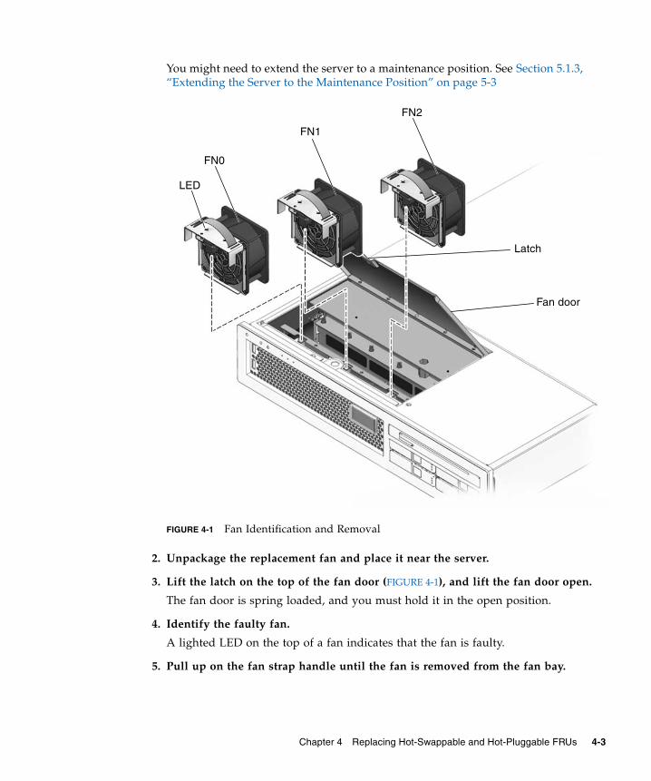
You might need to extend the server to a maintenance position. See Section 5.1.3,“Extending the Server to the Maintenance Position” on page 5-3
FIGURE 4-1 Fan Identification and Removal
2. Unpackage the replacement fan and place it near the server.
3. Lift the latch on the top of the fan door (FIGURE 4-1), and lift the fan door open.
The fan door is spring loaded, and you must hold it in the open position.
4. Identify the faulty fan.
A lighted LED on the top of a fan indicates that the fan is faulty.
5. Pull up on the fan strap handle until the fan is removed from the fan bay.
Latch
Fan door
FN1
FN2
FN0
LED
Chapter 4 Replacing Hot-Swappable and Hot-Pluggable FRUs 4-3
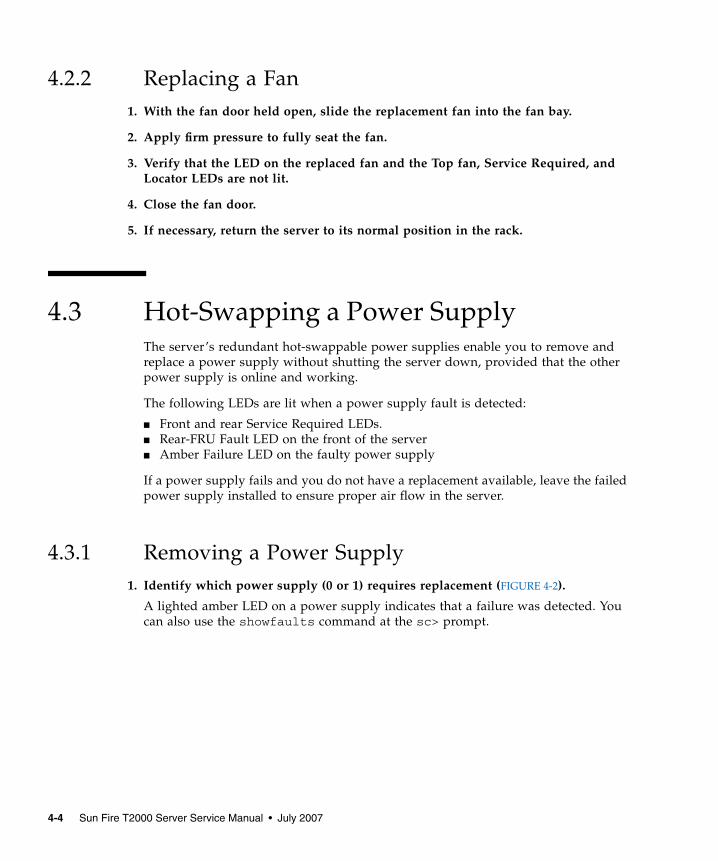
4.2.2 Replacing a Fan1. With the fan door held open, slide the replacement fan into the fan bay.
2. Apply firm pressure to fully seat the fan.
3. Verify that the LED on the replaced fan and the Top fan, Service Required, andLocator LEDs are not lit.
4. Close the fan door.
5. If necessary, return the server to its normal position in the rack.
4.3 Hot-Swapping a Power SupplyThe server’s redundant hot-swappable power supplies enable you to remove andreplace a power supply without shutting the server down, provided that the otherpower supply is online and working.
The following LEDs are lit when a power supply fault is detected:
■ Front and rear Service Required LEDs.■ Rear-FRU Fault LED on the front of the server■ Amber Failure LED on the faulty power supply
If a power supply fails and you do not have a replacement available, leave the failedpower supply installed to ensure proper air flow in the server.
4.3.1 Removing a Power Supply1. Identify which power supply (0 or 1) requires replacement (FIGURE 4-2).
A lighted amber LED on a power supply indicates that a failure was detected. Youcan also use the showfaults command at the sc> prompt.
4-4 Sun Fire T2000 Server Service Manual • July 2007
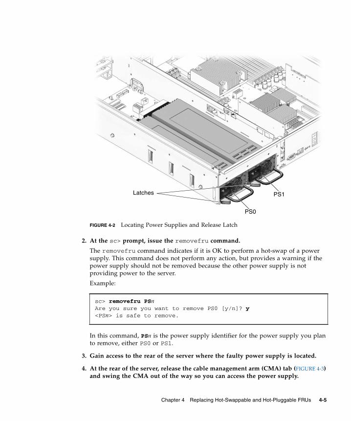
FIGURE 4-2 Locating Power Supplies and Release Latch
2. At the sc> prompt, issue the removefru command.
The removefru command indicates if it is OK to perform a hot-swap of a powersupply. This command does not perform any action, but provides a warning if thepower supply should not be removed because the other power supply is notproviding power to the server.
Example:
In this command, PSn is the power supply identifier for the power supply you planto remove, either PS0 or PS1.
3. Gain access to the rear of the server where the faulty power supply is located.
4. At the rear of the server, release the cable management arm (CMA) tab (FIGURE 4-3)and swing the CMA out of the way so you can access the power supply.
sc> removefru PSnAre you sure you want to remove PS0 [y/n]? y<PSn> is safe to remove.
PS1
PS0
Latches
Chapter 4 Replacing Hot-Swappable and Hot-Pluggable FRUs 4-5
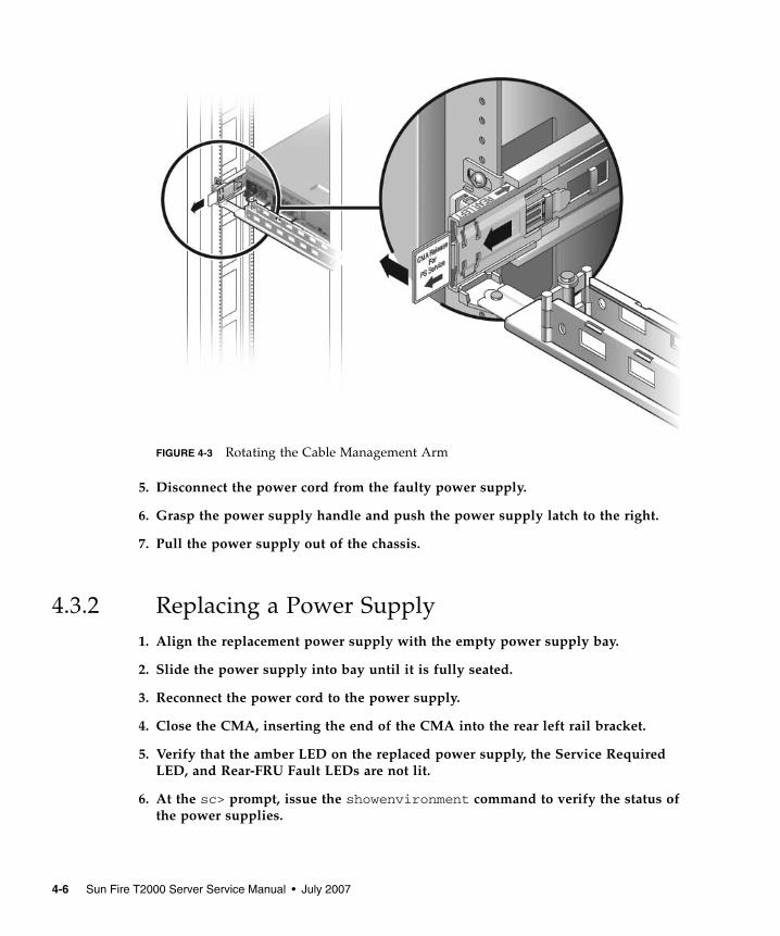
FIGURE 4-3 Rotating the Cable Management Arm
5. Disconnect the power cord from the faulty power supply.
6. Grasp the power supply handle and push the power supply latch to the right.
7. Pull the power supply out of the chassis.
4.3.2 Replacing a Power Supply1. Align the replacement power supply with the empty power supply bay.
2. Slide the power supply into bay until it is fully seated.
3. Reconnect the power cord to the power supply.
4. Close the CMA, inserting the end of the CMA into the rear left rail bracket.
5. Verify that the amber LED on the replaced power supply, the Service RequiredLED, and Rear-FRU Fault LEDs are not lit.
6. At the sc> prompt, issue the showenvironment command to verify the status ofthe power supplies.
4-6 Sun Fire T2000 Server Service Manual • July 2007
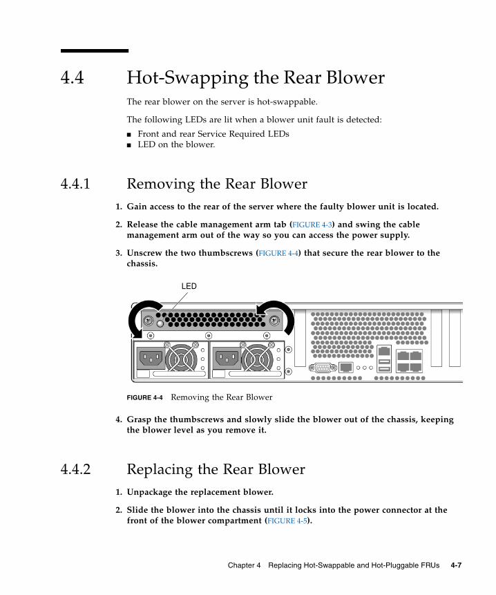
4.4 Hot-Swapping the Rear BlowerThe rear blower on the server is hot-swappable.
The following LEDs are lit when a blower unit fault is detected:
■ Front and rear Service Required LEDs■ LED on the blower.
4.4.1 Removing the Rear Blower1. Gain access to the rear of the server where the faulty blower unit is located.
2. Release the cable management arm tab (FIGURE 4-3) and swing the cablemanagement arm out of the way so you can access the power supply.
3. Unscrew the two thumbscrews (FIGURE 4-4) that secure the rear blower to thechassis.
FIGURE 4-4 Removing the Rear Blower
4. Grasp the thumbscrews and slowly slide the blower out of the chassis, keepingthe blower level as you remove it.
4.4.2 Replacing the Rear Blower1. Unpackage the replacement blower.
2. Slide the blower into the chassis until it locks into the power connector at thefront of the blower compartment (FIGURE 4-5).
LED
Chapter 4 Replacing Hot-Swappable and Hot-Pluggable FRUs 4-7
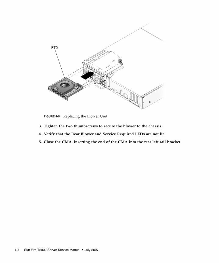
FIGURE 4-5 Replacing the Blower Unit
3. Tighten the two thumbscrews to secure the blower to the chassis.
4. Verify that the Rear Blower and Service Required LEDs are not lit.
5. Close the CMA, inserting the end of the CMA into the rear left rail bracket.
FT2
4-8 Sun Fire T2000 Server Service Manual • July 2007
4.5 Hot-Plugging a Hard DriveThe hard drives in the server are hot-pluggable, but this capability depends on howthe hard drives are configured. To hot-plug a drive you must be able to take thedrive offline (prevent any applications from accessing it, and remove the logicalsoftware links to it) before you can safely remove it.
The following situations inhibit the ability to perform hot-plugging of a drive:
■ The hard drive provides the operating system, and the operating system is notmirrored on another drive.
■ The hard drive cannot be logically isolated from the online operations of theserver
If your drive falls into these conditions, you must shut the system down before youreplace the hard drive. See Section 5.1.2, “Shutting the System Down” on page 5-2.
4.5.1 Removing a Hard Drive1. Identify the location of the hard drive that you want to replace (FIGURE 4-6).
Chapter 4 Replacing Hot-Swappable and Hot-Pluggable FRUs 4-9
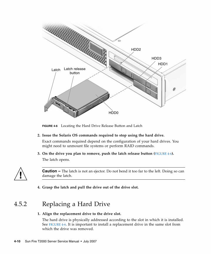
FIGURE 4-6 Locating the Hard Drive Release Button and Latch
2. Issue the Solaris OS commands required to stop using the hard drive.
Exact commands required depend on the configuration of your hard drives. Youmight need to unmount file systems or perform RAID commands.
3. On the drive you plan to remove, push the latch release button (FIGURE 4-6).
The latch opens.
Caution – The latch is not an ejector. Do not bend it too far to the left. Doing so candamage the latch.
4. Grasp the latch and pull the drive out of the drive slot.
4.5.2 Replacing a Hard Drive1. Align the replacement drive to the drive slot.
The hard drive is physically addressed according to the slot in which it is installed.See FIGURE 4-6. It is important to install a replacement drive in the same slot fromwhich the drive was removed.
Latch releaseLatch
HDD3
HDD1
HDD2
button
HDD0
4-10 Sun Fire T2000 Server Service Manual • July 2007
2. Slide the drive into the bay until it is fully seated.
3. Close the latch to lock the drive in place.
4. Perform administrative tasks to reconfigure the hard drive.
The procedures that you perform at this point depend on how your data isconfigured. You might need to partition the drive, create file systems, load data frombackups, or have data updated from a RAID configuration.
Chapter 4 Replacing Hot-Swappable and Hot-Pluggable FRUs 4-11

4-12 Sun Fire T2000 Server Service Manual • July 2007
CHAPTER 5
Replacing Cold-Swappable FRUs
This chapter describes how to remove and replace field-replaceable units (FRUs) inthe server that must be cold-swapped.
The following topics are covered:
■ Section 5.1, “Common Procedures for Parts Replacement” on page 5-1■ Section 5.2, “Removing and Replacing FRUs” on page 5-8■ Section 5.3, “Common Procedures for Finishing Up” on page 5-41
For a list of FRUs, see Appendix A.
Note – Never attempt to run the system with the cover removed. The cover must bein place for proper air flow. The cover interlock switch (intrusion switch)immediately shuts the system down when the cover is removed.
5.1 Common Procedures for PartsReplacementBefore you can remove and replace parts that are inside the server, you mustperform the following procedures:
■ Section 5.1.2, “Shutting the System Down” on page 5-2■ Section 5.1.3, “Extending the Server to the Maintenance Position” on page 5-3■ Section 5.1.6, “Performing Electrostatic Discharge Prevention Measures” on
page 5-6■ Section 5.1.5, “Disconnecting Power From the Server” on page 5-6■ Section 5.1.7, “Removing the Top Cover” on page 5-6■ Section 5.1.8, “Removing the Front Bezel and Top Front Cover” on page 5-7
5-1
Note – These procedures do not apply to the hot-pluggable and hot-swappabledevices (fans, power supplies, hard drives, and rear blower) described in Chapter 4.
The corresponding procedures that you perform when maintenance is complete aredescribed in Section 5.3, “Common Procedures for Finishing Up” on page 5-41.
5.1.1 Required ToolsThe server can be serviced with the following tools:
■ Antistatic wrist strap■ Antistatic mat■ No. 2 Phillips screwdriver
5.1.2 Shutting the System DownPerforming a graceful shutdown ensures that all of your data is saved and thesystem is ready for restart.
1. Log in as superuser or equivalent.
Depending on the nature of the problem, you might want to view the system status,the log files, or run diagnostics before you shut down the system. Refer to the SunFire T2000 Server Administration Guide for log file information.
2. Notify affected users.
Refer to your Solaris system administration documentation for additionalinformation.
3. Save any open files and quit all running programs.
Refer to your application documentation for specific information on these processes.
4. Shut down the Solaris OS.
Refer to the Solaris system administration documentation for additional information.
5. Switch from the system console to the ALOM CMT sc> prompt by typing the #.(Hash-Period) key sequence.
d. At the ALOM CMT sc> prompt, issue the poweroff command.
sc> poweroff -fySC Alert: SC Request to Power Off Host Immediately.
5-2 Sun Fire T2000 Server Service Manual • July 2007
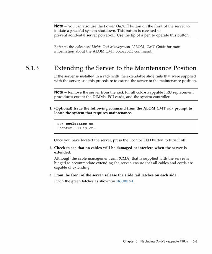
Note – You can also use the Power On/Off button on the front of the server toinitiate a graceful system shutdown. This button is recessed toprevent accidental server power-off. Use the tip of a pen to operate this button.
Refer to the Advanced Lights Out Management (ALOM) CMT Guide for moreinformation about the ALOM CMT poweroff command.
5.1.3 Extending the Server to the Maintenance PositionIf the server is installed in a rack with the extendable slide rails that were suppliedwith the server, use this procedure to extend the server to the maintenance position.
Note – Remove the server from the rack for all cold-swappable FRU replacementprocedures except the DIMMs, PCI cards, and the system controller.
1. (Optional) Issue the following command from the ALOM CMT sc> prompt tolocate the system that requires maintenance.
Once you have located the server, press the Locator LED button to turn it off.
2. Check to see that no cables will be damaged or interfere when the server isextended.
Although the cable management arm (CMA) that is supplied with the server ishinged to accommodate extending the server, ensure that all cables and cords arecapable of extending.
3. From the front of the server, release the slide rail latches on each side.
Pinch the green latches as shown in FIGURE 5-1.
sc> setlocator onLocator LED is on.
Chapter 5 Replacing Cold-Swappable FRUs 5-3
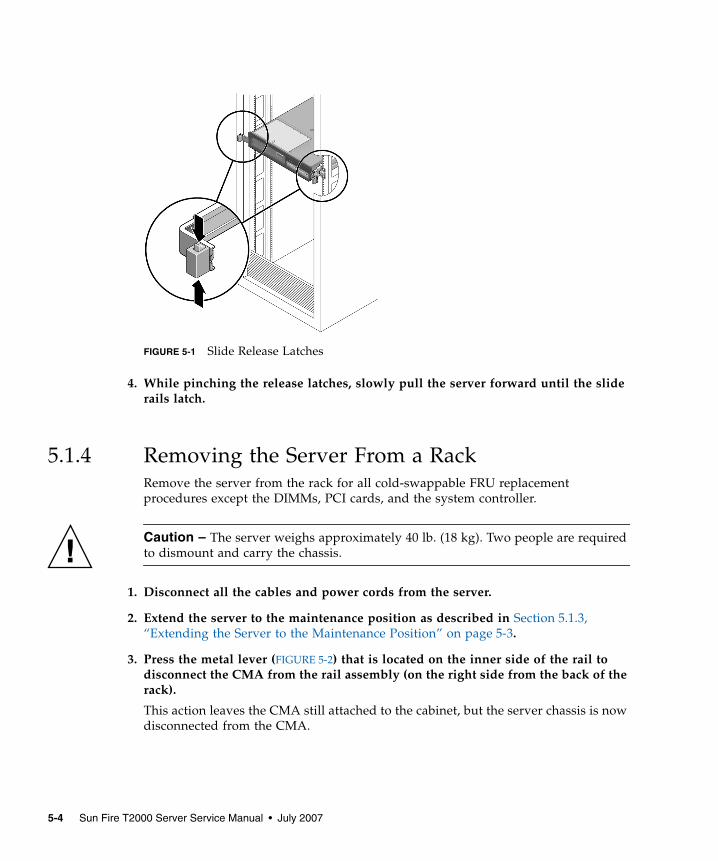
FIGURE 5-1 Slide Release Latches
4. While pinching the release latches, slowly pull the server forward until the sliderails latch.
5.1.4 Removing the Server From a RackRemove the server from the rack for all cold-swappable FRU replacementprocedures except the DIMMs, PCI cards, and the system controller.
Caution – The server weighs approximately 40 lb. (18 kg). Two people are requiredto dismount and carry the chassis.
1. Disconnect all the cables and power cords from the server.
2. Extend the server to the maintenance position as described in Section 5.1.3,“Extending the Server to the Maintenance Position” on page 5-3.
3. Press the metal lever (FIGURE 5-2) that is located on the inner side of the rail todisconnect the CMA from the rail assembly (on the right side from the back of therack).
This action leaves the CMA still attached to the cabinet, but the server chassis is nowdisconnected from the CMA.
5-4 Sun Fire T2000 Server Service Manual • July 2007
FIGURE 5-2 Locating the Metal Lever
Caution – The server weighs approximately 40 lb. (18 kg). The next step requirestwo people to dismount and carry the chassis.
4. From the front of the server, pull the release tabs forward and pull the serverforward until it is free of the rack rails.
The release tabs are located on each rail, about midway on the server.
5. Set the server on a sturdy work surface.
Chapter 5 Replacing Cold-Swappable FRUs 5-5
5.1.5 Disconnecting Power From the Server
Caution – The system supplies standby power to the circuit boards even when thesystem is powered off.
● Disconnect both power cords from the power supplies.
Note – The following FRU replacements do not require that power be removed:DIMMs and PCI cards.
5.1.6 Performing Electrostatic Discharge PreventionMeasures
1. Prepare an antistatic surface on which to set parts during removal and installation.
Place ESD-sensitive components such as the printed circuit boards on an antistaticmat. The following items can be used as an antistatic mat:
■ Antistatic bag used to wrap a Sun replacement part
■ Sun ESD mat, part number 250-1088
■ Disposable ESD mat (shipped with some replacement parts or optional systemcomponents)
2. Attach an antistatic wrist strap.
When servicing or removing server components, attach an antistatic strap to yourwrist and then to a metal area on the chassis. Do this after you disconnect the powercords from the server.
5.1.7 Removing the Top CoverAll field-replaceable units (FRUs) that are not hot-swappable require the removal ofthe top cover.
5-6 Sun Fire T2000 Server Service Manual • July 2007
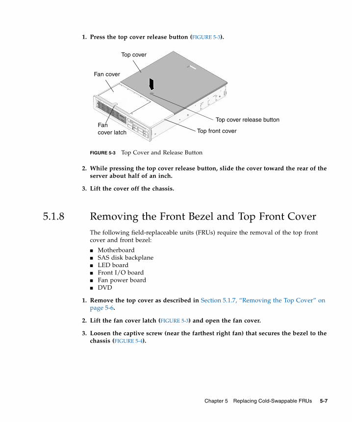
1. Press the top cover release button (FIGURE 5-3).
FIGURE 5-3 Top Cover and Release Button
2. While pressing the top cover release button, slide the cover toward the rear of theserver about half of an inch.
3. Lift the cover off the chassis.
5.1.8 Removing the Front Bezel and Top Front CoverThe following field-replaceable units (FRUs) require the removal of the top frontcover and front bezel:
■ Motherboard■ SAS disk backplane■ LED board■ Front I/O board■ Fan power board■ DVD
1. Remove the top cover as described in Section 5.1.7, “Removing the Top Cover” onpage 5-6.
2. Lift the fan cover latch (FIGURE 5-3) and open the fan cover.
3. Loosen the captive screw (near the farthest right fan) that secures the bezel to thechassis (FIGURE 5-4).
Fancover latch Top front cover
Fan cover
Top cover
Top cover release button
Chapter 5 Replacing Cold-Swappable FRUs 5-7
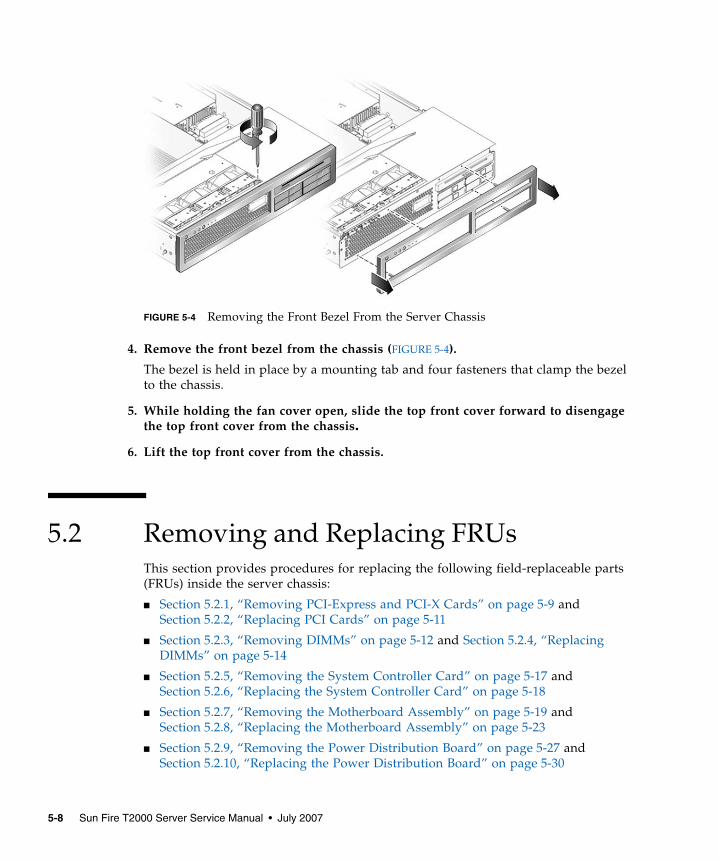
FIGURE 5-4 Removing the Front Bezel From the Server Chassis
4. Remove the front bezel from the chassis (FIGURE 5-4).
The bezel is held in place by a mounting tab and four fasteners that clamp the bezelto the chassis.
5. While holding the fan cover open, slide the top front cover forward to disengagethe top front cover from the chassis.
6. Lift the top front cover from the chassis.
5.2 Removing and Replacing FRUsThis section provides procedures for replacing the following field-replaceable parts(FRUs) inside the server chassis:
■ Section 5.2.1, “Removing PCI-Express and PCI-X Cards” on page 5-9 andSection 5.2.2, “Replacing PCI Cards” on page 5-11
■ Section 5.2.3, “Removing DIMMs” on page 5-12 and Section 5.2.4, “ReplacingDIMMs” on page 5-14
■ Section 5.2.5, “Removing the System Controller Card” on page 5-17 andSection 5.2.6, “Replacing the System Controller Card” on page 5-18
■ Section 5.2.7, “Removing the Motherboard Assembly” on page 5-19 andSection 5.2.8, “Replacing the Motherboard Assembly” on page 5-23
■ Section 5.2.9, “Removing the Power Distribution Board” on page 5-27 andSection 5.2.10, “Replacing the Power Distribution Board” on page 5-30
5-8 Sun Fire T2000 Server Service Manual • July 2007
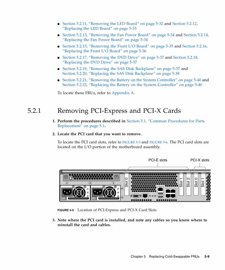
■ Section 5.2.11, “Removing the LED Board” on page 5-32 and Section 5.2.12,“Replacing the LED Board” on page 5-33
■ Section 5.2.13, “Removing the Fan Power Board” on page 5-34 and Section 5.2.14,“Replacing the Fan Power Board” on page 5-34
■ Section 5.2.15, “Removing the Front I/O Board” on page 5-35 and Section 5.2.16,“Replacing the Front I/O Board” on page 5-36
■ Section 5.2.17, “Removing the DVD Drive” on page 5-37 and Section 5.2.18,“Replacing the DVD Drive” on page 5-37
■ Section 5.2.19, “Removing the SAS Disk Backplane” on page 5-37 andSection 5.2.20, “Replacing the SAS Disk Backplane” on page 5-38
■ Section 5.2.21, “Removing the Battery on the System Controller” on page 5-40 andSection 5.2.22, “Replacing the Battery on the System Controller” on page 5-40
To locate these FRUs, refer to Appendix A.
5.2.1 Removing PCI-Express and PCI-X Cards1. Perform the procedures described in Section 5.1, “Common Procedures for Parts
Replacement” on page 5-1.
2. Locate the PCI card that you want to remove.
To locate the PCI card slots, refer to FIGURE 5-5 and FIGURE 5-6. The PCI card slots arelocated on the I/O portion of the motherboard assembly.
FIGURE 5-5 Location of PCI-Express and PCI-X Card Slots
3. Note where the PCI card is installed, and note any cables so you know where toreinstall the card and cables.
Slo
t 0
Slo
t 2
Slo
t 0
Slo
t 1
Slo
t 1
PCI-E slots PCI-X slots
Chapter 5 Replacing Cold-Swappable FRUs 5-9
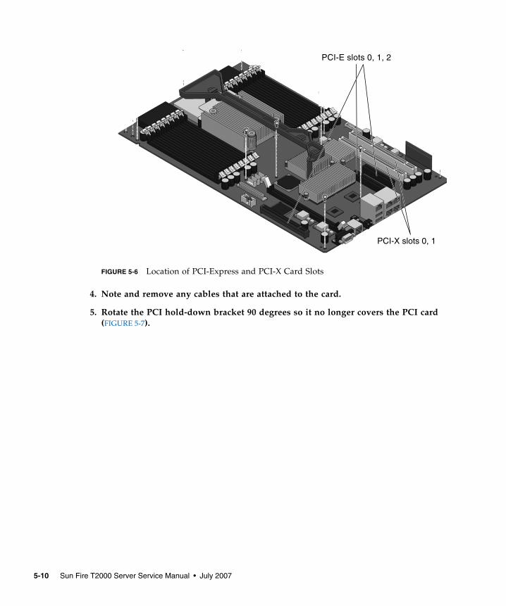
FIGURE 5-6 Location of PCI-Express and PCI-X Card Slots
4. Note and remove any cables that are attached to the card.
5. Rotate the PCI hold-down bracket 90 degrees so it no longer covers the PCI card(FIGURE 5-7).
PCI-E slots 0, 1, 2
PCI-X slots 0, 1
5-10 Sun Fire T2000 Server Service Manual • July 2007
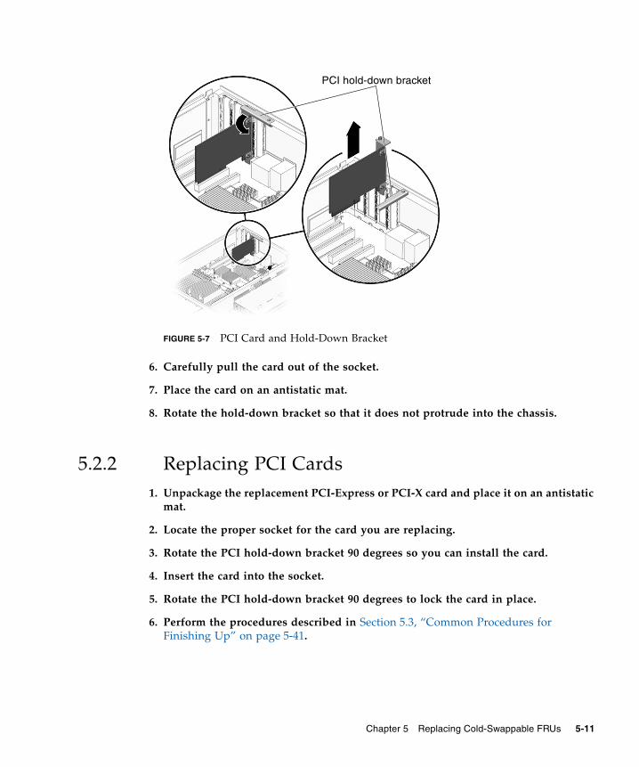
FIGURE 5-7 PCI Card and Hold-Down Bracket
6. Carefully pull the card out of the socket.
7. Place the card on an antistatic mat.
8. Rotate the hold-down bracket so that it does not protrude into the chassis.
5.2.2 Replacing PCI Cards1. Unpackage the replacement PCI-Express or PCI-X card and place it on an antistatic
mat.
2. Locate the proper socket for the card you are replacing.
3. Rotate the PCI hold-down bracket 90 degrees so you can install the card.
4. Insert the card into the socket.
5. Rotate the PCI hold-down bracket 90 degrees to lock the card in place.
6. Perform the procedures described in Section 5.3, “Common Procedures forFinishing Up” on page 5-41.
PCI hold-down bracket
Chapter 5 Replacing Cold-Swappable FRUs 5-11

5.2.3 Removing DIMMs
Note – Not all DIMMs detected as faulty and offlined by POST must be replaced. Inservice (maximum) mode, POST detects memory devices with errors that might becorrected with Solaris PSH. See Section 3.4.5, “Correctable Errors Detected by POST”on page 3-36.
Caution – This procedure requires that you handle components that are sensitive tostatic discharges that can cause the component to fail. To avoid this problem, ensurethat you follow antistatic practices as described in Section 5.1.6, “PerformingElectrostatic Discharge Prevention Measures” on page 5-6.
1. Perform the procedures described in Section 5.1, “Common Procedures for PartsReplacement” on page 5-1.
2. Locate the DIMMs (FIGURE 5-8) that you want to replace.
Use FIGURE 5-8 and TABLE 5-1 to identify the DIMMs you want to remove.
Note – For memory configuration information see Section 6.2.1, “MemoryGuidelines” on page 6-4.
5-12 Sun Fire T2000 Server Service Manual • July 2007
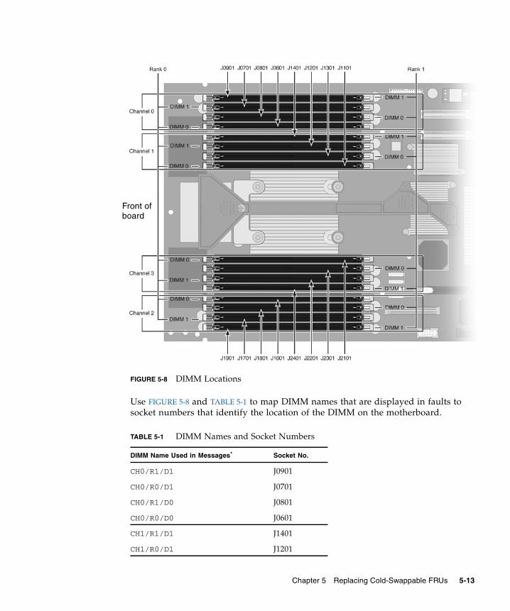
FIGURE 5-8 DIMM Locations
Use FIGURE 5-8 and TABLE 5-1 to map DIMM names that are displayed in faults tosocket numbers that identify the location of the DIMM on the motherboard.
TABLE 5-1 DIMM Names and Socket Numbers
DIMM Name Used in Messages* Socket No.
CH0/R1/D1 J0901
CH0/R0/D1 J0701
CH0/R1/D0 J0801
CH0/R0/D0 J0601
CH1/R1/D1 J1401
CH1/R0/D1 J1201
Front ofboard
Chapter 5 Replacing Cold-Swappable FRUs 5-13
3. Note the DIMM locations so you can install the replacement DIMMs in the samesockets.
4. Push down on the ejector levers on each side of the DIMM connector until theDIMM is released.
5. Grasp the top corners of the faulty DIMM and remove it from the system.
6. Place DIMMs on an antistatic mat.
5.2.4 Replacing DIMMs1. Unpackage the replacement DIMMs and place them on an antistatic mat.
2. Ensure that the connector ejector tabs are in the open position.
3. Line up the replacement DIMM with the connector.
Align the DIMM notch with the key in the connector. This action ensures that theDIMM is oriented correctly.
4. Push the DIMM into the connector until the ejector tabs lock the DIMM in place.
5. Perform the procedures described in Section 5.3, “Common Procedures forFinishing Up” on page 5-41.
CH1/R1/D0 J1301
CH1/R0/D0 J1101
CH2/R1/D1 J1901
CH2/R0/D1 J1701
CH2/R1/D0 J1801
CH2/R0/D0 J1601
CH3/R1/D1 J2401
CH3/R0/D1 J2201
CH3/R1/D0 J2301
CH3/R0/D0 J2101
* DIMM names in messages are displayed with the full namesuch as MB/CMP0/CH1/R1/D1. This table omits the preced-ing MB/CMP0 for clarity.
TABLE 5-1 DIMM Names and Socket Numbers (Continued)
DIMM Name Used in Messages* Socket No.
5-14 Sun Fire T2000 Server Service Manual • July 2007
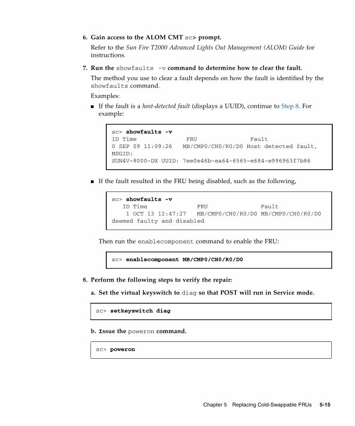
6. Gain access to the ALOM CMT sc> prompt.
Refer to the Sun Fire T2000 Advanced Lights Out Management (ALOM) Guide forinstructions.
7. Run the showfaults -v command to determine how to clear the fault.
The method you use to clear a fault depends on how the fault is identified by theshowfaults command.
Examples:
■ If the fault is a host-detected fault (displays a UUID), continue to Step 8. Forexample:
■ If the fault resulted in the FRU being disabled, such as the following,
Then run the enablecomponent command to enable the FRU:
8. Perform the following steps to verify the repair:
a. Set the virtual keyswitch to diag so that POST will run in Service mode.
b. Issue the poweron command.
sc> showfaults -vID Time FRU Fault0 SEP 09 11:09:26 MB/CMP0/CH0/R0/D0 Host detected fault,MSGID:SUN4V-8000-DX UUID: 7ee0e46b-ea64-6565-e684-e996963f7b86
sc> showfaults -v ID Time FRU Fault 1 OCT 13 12:47:27 MB/CMP0/CH0/R0/D0 MB/CMP0/CH0/R0/D0deemed faulty and disabled
sc> enablecomponent MB/CMP0/CH0/R0/D0
sc> setkeyswitch diag
sc> poweron
Chapter 5 Replacing Cold-Swappable FRUs 5-15
c. Switch to the system console to view POST output.
Watch the POST output for possible fault messages. The following output is asign that POST did not detect any faults:
Note – Depending on the configuration of ALOM CMT POST variables andwhether POST detected faults or not, the system might boot, or the system mightremain at the ok prompt. If the system is at the ok prompt, type boot.
d. Return the virtual keyswitch to normal mode.
e. Issue the Solaris OS fmadm faulty command.
No memory or DIMM faults should be displayed.
If faults are reported, refer to the diagnostics flowchart in FIGURE 3-1 for an approachto diagnose the fault.
9. Gain access to the ALOM CMT sc> prompt.
10. Run the showfaults command.
sc> console
.
.
.0:0>POST Passed all devices.0:0>0:0>DEMON: (Diagnostics Engineering MONitor)0:0>Select one of the following functions0:0>POST:Return to OBP.0:0>INFO:0:0>POST Passed all devices.0:0>Master set ACK for vbsc runpost command and spin...
sc> setkeyswitch normal
# fmadm faulty
5-16 Sun Fire T2000 Server Service Manual • July 2007
■ If the fault was detected by the host and the fault information persists, the outputwill be similar to the following example:
■ If the showfaults command does not report a fault with a UUID, then you donot need to proceed with the following steps because the fault is cleared.
11. Run the clearfault command.
12. Switch to the system console.
13. Issue the fmadm repair command with the UUID.
Use the same UUID that you used with the clearfault command.
5.2.5 Removing the System Controller Card
Caution – The system controller card can be hot. To avoid injury, handle it carefully.
1. Perform the procedures described in Section 5.1, “Common Procedures for PartsReplacement” on page 5-1.
2. Locate the system controller card.
See Appendix A for an illustration of the servers FRUs that shows the systemcontroller card.
3. Push down on the ejector levers on each side of the system controller until thecard is released from the socket.
sc> showfaults -vID Time FRU Fault0 SEP 09 11:09:26 MB/CMP0/CH0/R0/D0 Host detected fault, MSGID:SUN4U-8000-2S UUID: 7ee0e46b-ea64-6565-e684-e996963f7b86
sc> clearfault 7ee0e46b-ea64-6565-e684-e996963f7b86
sc> console
# fmadm repair 7ee0e46b-ea64-6565-e684-e996963f7b86
Chapter 5 Replacing Cold-Swappable FRUs 5-17
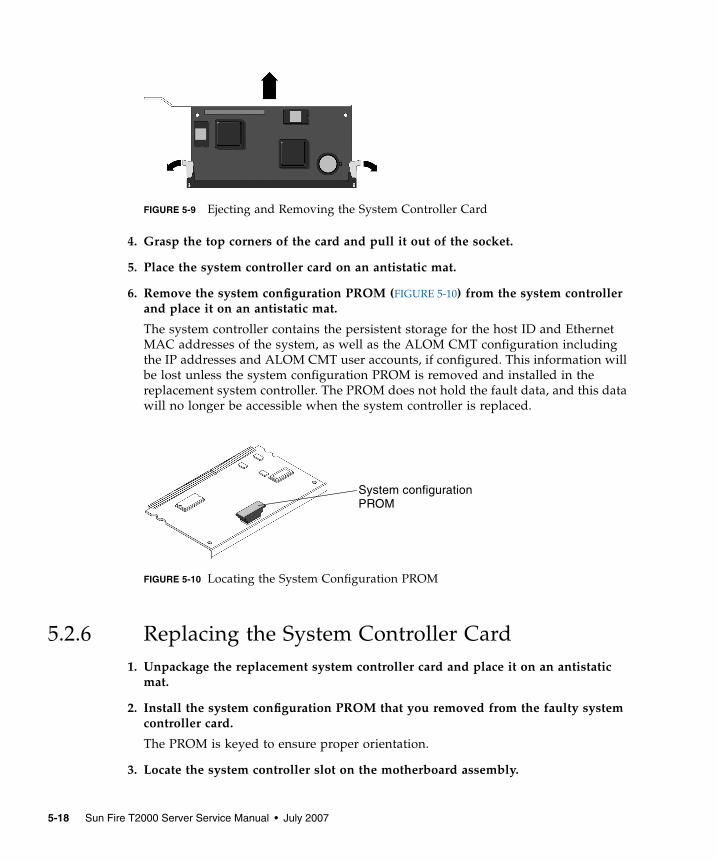
FIGURE 5-9 Ejecting and Removing the System Controller Card
4. Grasp the top corners of the card and pull it out of the socket.
5. Place the system controller card on an antistatic mat.
6. Remove the system configuration PROM (FIGURE 5-10) from the system controllerand place it on an antistatic mat.
The system controller contains the persistent storage for the host ID and EthernetMAC addresses of the system, as well as the ALOM CMT configuration includingthe IP addresses and ALOM CMT user accounts, if configured. This information willbe lost unless the system configuration PROM is removed and installed in thereplacement system controller. The PROM does not hold the fault data, and this datawill no longer be accessible when the system controller is replaced.
FIGURE 5-10 Locating the System Configuration PROM
5.2.6 Replacing the System Controller Card1. Unpackage the replacement system controller card and place it on an antistatic
mat.
2. Install the system configuration PROM that you removed from the faulty systemcontroller card.
The PROM is keyed to ensure proper orientation.
3. Locate the system controller slot on the motherboard assembly.
System configurationPROM
5-18 Sun Fire T2000 Server Service Manual • July 2007
4. Ensure that the ejector levers are open.
5. Holding the bottom edge of the system controller parallel to its socket, carefullyalign the system controller so that each of its contacts is centered on a socket pin.
Ensure that the system controller is correctly oriented. A notch along the bottom ofthe system controller corresponds to a tab on the socket.
6. Push firmly and evenly on both ends of the system controller until it is firmlyseated in the socket.
You hear a click when the ejector levers lock into place.
7. Perform the procedures described in Section 5.3, “Common Procedures forFinishing Up” on page 5-41.
5.2.7 Removing the Motherboard AssemblyThe motherboard for your server has two distinct boards for the CPU and the I/Oboard. However, they must be removed and replaced as a single motherboardassembly (FIGURE 5-11).
Caution – The front bezel and fan cover must be removed before removing themotherboard assembly. Attempting to remove the motherboard assembly withoutthe front bezel and fan cover removed can cause severe damage.
Caution – Remove and replace the motherboard carefully. The motherboard restson metal standoffs. If the motherboard is not handled carefully, the componentsmounted on the underside of the motherboard can be damaged if they hit thestandoffs. To ensure that this damage does not occur, perform the removal andreplacement instructions described in this document.
Caution – A flexible cable connects the CPU and I/O boards. This flexible cable isfragile. Handle these parts very carefully to prevent damage.
Caution – This procedure requires that you handle components that are sensitive tostatic discharges that can cause the component to fail. To avoid this problem, ensurethat you follow antistatic practices as described in Section 5.1.6, “PerformingElectrostatic Discharge Prevention Measures” on page 5-6.
Chapter 5 Replacing Cold-Swappable FRUs 5-19
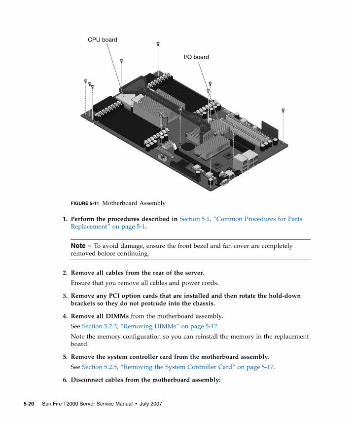
FIGURE 5-11 Motherboard Assembly
1. Perform the procedures described in Section 5.1, “Common Procedures for PartsReplacement” on page 5-1.
Note – To avoid damage, ensure the front bezel and fan cover are completelyremoved before continuing.
2. Remove all cables from the rear of the server.
Ensure that you remove all cables and power cords.
3. Remove any PCI option cards that are installed and then rotate the hold-downbrackets so they do not protrude into the chassis.
4. Remove all DIMMs from the motherboard assembly.
See Section 5.2.3, “Removing DIMMs” on page 5-12.
Note the memory configuration so you can reinstall the memory in the replacementboard.
5. Remove the system controller card from the motherboard assembly.
See Section 5.2.5, “Removing the System Controller Card” on page 5-17.
6. Disconnect cables from the motherboard assembly:
I/O board
CPU board
5-20 Sun Fire T2000 Server Service Manual • July 2007
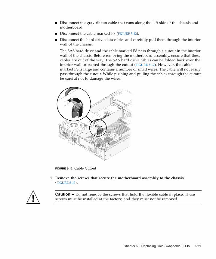
■ Disconnect the gray ribbon cable that runs along the left side of the chassis andmotherboard.
■ Disconnect the cable marked P8 (FIGURE 5-12).
■ Disconnect the hard drive data cables and carefully pull them through the interiorwall of the chassis.
The SAS hard drive and the cable marked P8 pass through a cutout in the interiorwall of the chassis. Before removing the motherboard assembly, ensure that thesecables are out of the way. The SAS hard drive cables can be folded back over theinterior wall or passed through the cutout (FIGURE 5-12). However, the cablemarked P8 is large and contains a number of small wires. The cable will not easilypass through the cutout. While pushing and pulling the cables through the cutoutbe careful not to damage the wires.
FIGURE 5-12 Cable Cutout
7. Remove the screws that secure the motherboard assembly to the chassis(FIGURE 5-13).
Caution – Do not remove the screws that hold the flexible cable in place. Thesescrews must be installed at the factory, and they must not be removed.
Chapter 5 Replacing Cold-Swappable FRUs 5-21

FIGURE 5-13 Location of the Screws in the Motherboard Assembly
8. Lift the front of the motherboard to clear the front standoffs.
The front of the motherboard refers to the part of the motherboard nearest the frontof the server.
9. Slide the motherboard forward to clear the connectors from the cutouts in the rearof the chassis.
Flexible cable(do not remove flex cable screws)
5-22 Sun Fire T2000 Server Service Manual • July 2007
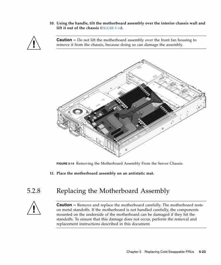
10. Using the handle, tilt the motherboard assembly over the interior chassis wall andlift it out of the chassis (FIGURE 5-14).
Caution – Do not lift the motherboard assembly over the front fan housing toremove it from the chassis, because doing so can damage the assembly.
FIGURE 5-14 Removing the Motherboard Assembly From the Server Chassis.
11. Place the motherboard assembly on an antistatic mat.
5.2.8 Replacing the Motherboard Assembly
Caution – Remove and replace the motherboard carefully. The motherboard restson metal standoffs. If the motherboard is not handled carefully, the componentsmounted on the underside of the motherboard can be damaged if they hit thestandoffs. To ensure that this damage does not occur, perform the removal andreplacement instructions described in this document.
Chapter 5 Replacing Cold-Swappable FRUs 5-23
Caution – A flexible cable connects the CPU and I/O boards. This flexible cable isfragile. Handle these parts very carefully to prevent damage.
Caution – This procedure requires that you handle components that are sensitive tostatic discharges that can cause the component to fail. To avoid this problem, ensurethat you follow antistatic practices as described in Section 5.1.6, “PerformingElectrostatic Discharge Prevention Measures” on page 5-6.
1. Unpackage the replacement motherboard assembly and place it on an antistaticmat.
2. Tilt the motherboard assembly over the interior wall into the chassis (FIGURE 5-15)and place it down on the rear standoffs
Avoid touching the front standoffs with the motherboard.
3. Slide the motherboard backward on the rear standoffs to engage the connectors inthe rear cutouts.
4. Place the front of the motherboard down on the front standoffs.
The front of the motherboard refers to the part of the motherboard nearest the frontof the server.
5-24 Sun Fire T2000 Server Service Manual • July 2007
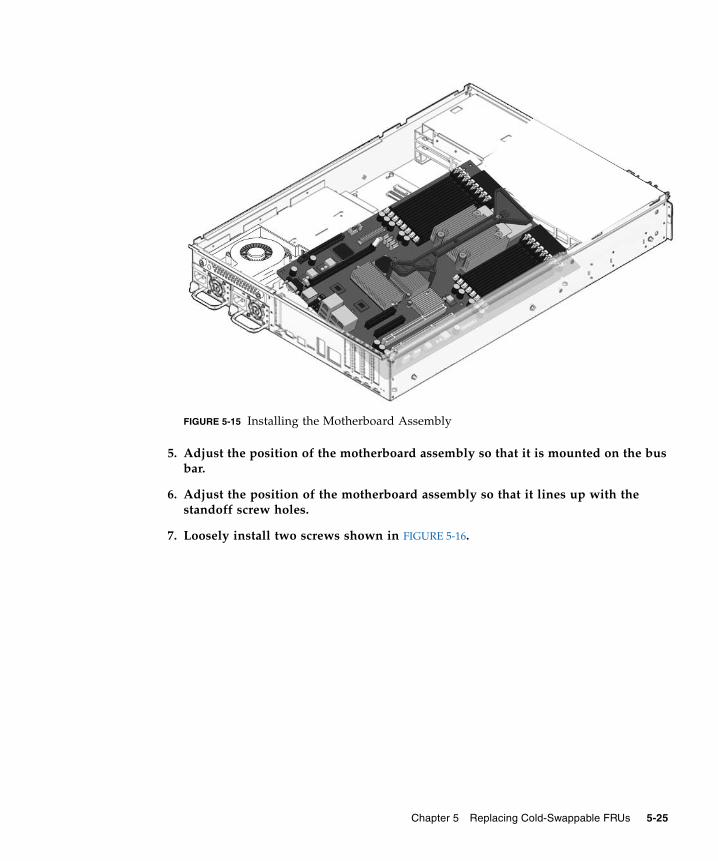
FIGURE 5-15 Installing the Motherboard Assembly
5. Adjust the position of the motherboard assembly so that it is mounted on the busbar.
6. Adjust the position of the motherboard assembly so that it lines up with thestandoff screw holes.
7. Loosely install two screws shown in FIGURE 5-16.
Chapter 5 Replacing Cold-Swappable FRUs 5-25
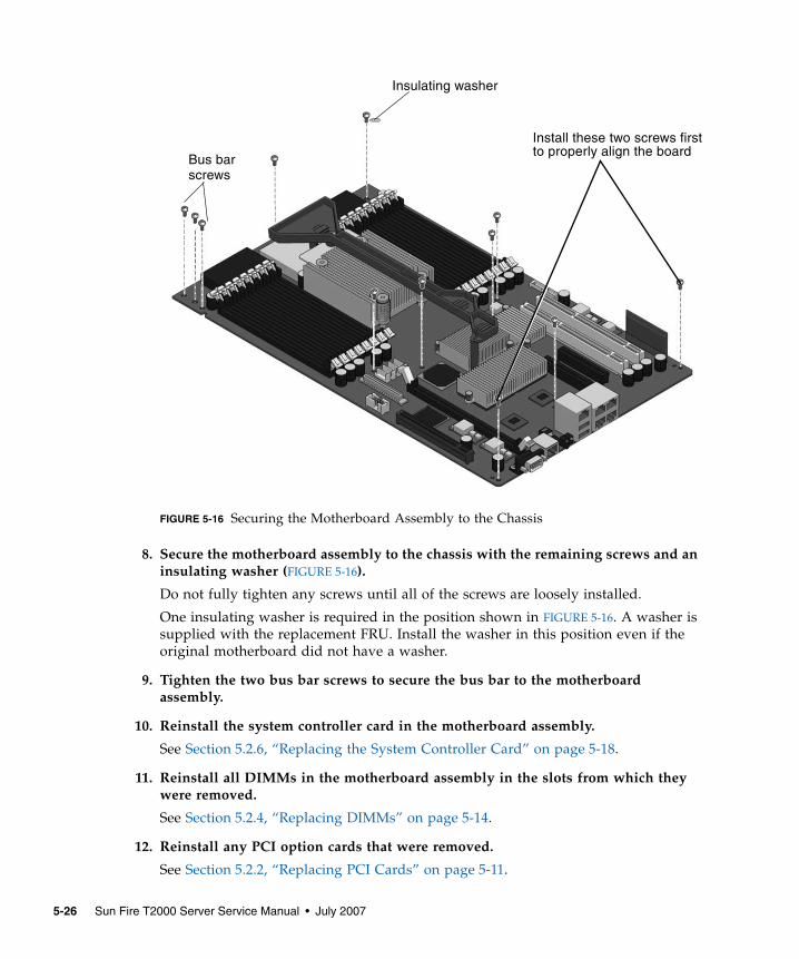
FIGURE 5-16 Securing the Motherboard Assembly to the Chassis
8. Secure the motherboard assembly to the chassis with the remaining screws and aninsulating washer (FIGURE 5-16).
Do not fully tighten any screws until all of the screws are loosely installed.
One insulating washer is required in the position shown in FIGURE 5-16. A washer issupplied with the replacement FRU. Install the washer in this position even if theoriginal motherboard did not have a washer.
9. Tighten the two bus bar screws to secure the bus bar to the motherboardassembly.
10. Reinstall the system controller card in the motherboard assembly.
See Section 5.2.6, “Replacing the System Controller Card” on page 5-18.
11. Reinstall all DIMMs in the motherboard assembly in the slots from which theywere removed.
See Section 5.2.4, “Replacing DIMMs” on page 5-14.
12. Reinstall any PCI option cards that were removed.
See Section 5.2.2, “Replacing PCI Cards” on page 5-11.
Bus barscrews
Install these two screws firstto properly align the board
Insulating washer
5-26 Sun Fire T2000 Server Service Manual • July 2007
13. Reconnect the cables to the motherboard:
■ Reconnect the cable marked P8 to the I/O board.
■ Reconnect the gray ribbon cable that runs along the left side of the chassis.
■ Pull the hard drive data cables through the interior wall of the chassis andreconnect the cables to the motherboard.
14. Reconnect all cables that were removed from the rear of the server.
15. Perform the procedures described in Section 5.3, “Common Procedures forFinishing Up” on page 5-41.
5.2.9 Removing the Power Distribution BoardThe power distribution board (PDB) provides the circuitry that distributes power tothe other components in the system. The PDB also contains an electronic copy of thechassis serial number (see Section 2.3, “Obtaining the Chassis Serial Number” onpage 2-10). When you replace this board, you must run certain service commands toupdate the replacement PDB with the chassis serial number. The steps to performthese service commands are provided in Section 5.2.10, “Replacing the PowerDistribution Board” on page 5-30.
Caution – The system supplies power to the power distribution board even whenthe system is powered off. To avoid personal injury or damage to the system, youmust disconnect power cords before servicing the PDB.
1. Perform the procedures described in Section 5.1, “Common Procedures for PartsReplacement” on page 5-1.
2. Disengage both power supplies from the power distribution board.
To disengage a power supply, push the power supply latch to the right and pull thepower supply out a few inches to disengage it from the PDB (FIGURE 5-17).
Chapter 5 Replacing Cold-Swappable FRUs 5-27
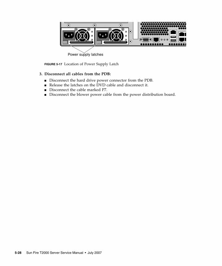
FIGURE 5-17 Location of Power Supply Latch
3. Disconnect all cables from the PDB:
■ Disconnect the hard drive power connector from the PDB.■ Release the latches on the DVD cable and disconnect it.■ Disconnect the cable marked P7.■ Disconnect the blower power cable from the power distribution board.
Power supply latches
5-28 Sun Fire T2000 Server Service Manual • July 2007
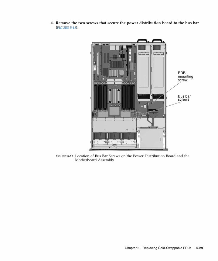
4. Remove the two screws that secure the power distribution board to the bus bar(FIGURE 5-18).
FIGURE 5-18 Location of Bus Bar Screws on the Power Distribution Board and theMotherboard Assembly
Bus barscrews
PDBmountingscrew
Chapter 5 Replacing Cold-Swappable FRUs 5-29
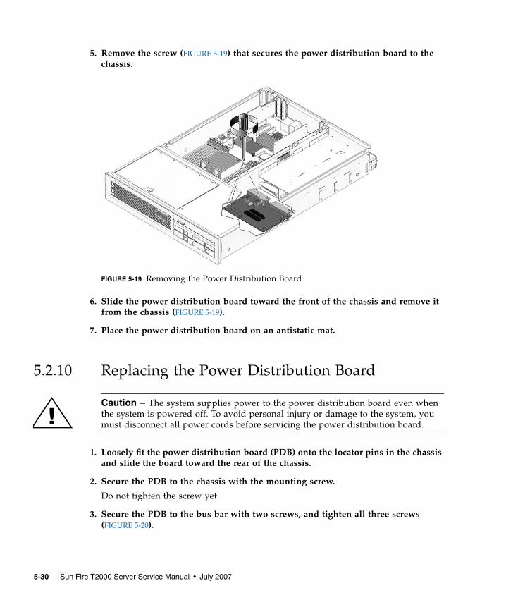
5. Remove the screw (FIGURE 5-19) that secures the power distribution board to thechassis.
FIGURE 5-19 Removing the Power Distribution Board
6. Slide the power distribution board toward the front of the chassis and remove itfrom the chassis (FIGURE 5-19).
7. Place the power distribution board on an antistatic mat.
5.2.10 Replacing the Power Distribution Board
Caution – The system supplies power to the power distribution board even whenthe system is powered off. To avoid personal injury or damage to the system, youmust disconnect all power cords before servicing the power distribution board.
1. Loosely fit the power distribution board (PDB) onto the locator pins in the chassisand slide the board toward the rear of the chassis.
2. Secure the PDB to the chassis with the mounting screw.
Do not tighten the screw yet.
3. Secure the PDB to the bus bar with two screws, and tighten all three screws(FIGURE 5-20).
5-30 Sun Fire T2000 Server Service Manual • July 2007
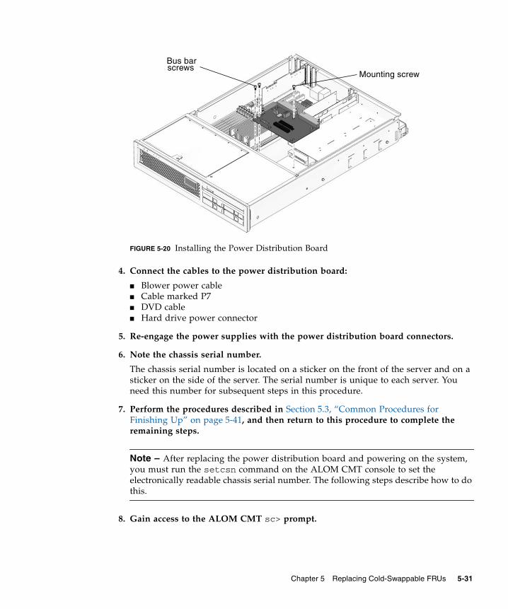
FIGURE 5-20 Installing the Power Distribution Board
4. Connect the cables to the power distribution board:
■ Blower power cable■ Cable marked P7■ DVD cable■ Hard drive power connector
5. Re-engage the power supplies with the power distribution board connectors.
6. Note the chassis serial number.
The chassis serial number is located on a sticker on the front of the server and on asticker on the side of the server. The serial number is unique to each server. Youneed this number for subsequent steps in this procedure.
7. Perform the procedures described in Section 5.3, “Common Procedures forFinishing Up” on page 5-41, and then return to this procedure to complete theremaining steps.
Note – After replacing the power distribution board and powering on the system,you must run the setcsn command on the ALOM CMT console to set theelectronically readable chassis serial number. The following steps describe how to dothis.
8. Gain access to the ALOM CMT sc> prompt.
Mounting screw
Bus barscrews
Chapter 5 Replacing Cold-Swappable FRUs 5-31
9. Perform the following service commands to set the electronic chassis serialnumber in the power distribution board:
Caution – Once the power distribution board is programmed with an electronicchassis serial number, the serial number cannot be changed. When executing thefollowing commands, ensure that you run the commands correctly and that youenter the correct chassis serial number because you will not be able to change it.The chassis serial number is used to obtain support from Sun.
5.2.11 Removing the LED Board1. Perform the procedures described in Section 5.1, “Common Procedures for Parts
Replacement” on page 5-1.
2. Remove all three fans.
See Section 4.2.1, “Removing a Fan” on page 4-2.
sc> setsc sc_servicemode trueWarning: misuse of this mode may invalidate your warranty.sc> setcsn -c chassis_serial_numberAre you sure you want to permanently set the Chassis Serial Numberto chassis_serial_number [y/n]? yChassis serial number recorded.sc> showplatformSUNW,Sun-Fire-T2000Chassis Serial Number: chassis-serial-numberDomain Status------ ------S0 Runningsc>setsc sc_servicemode false
5-32 Sun Fire T2000 Server Service Manual • July 2007
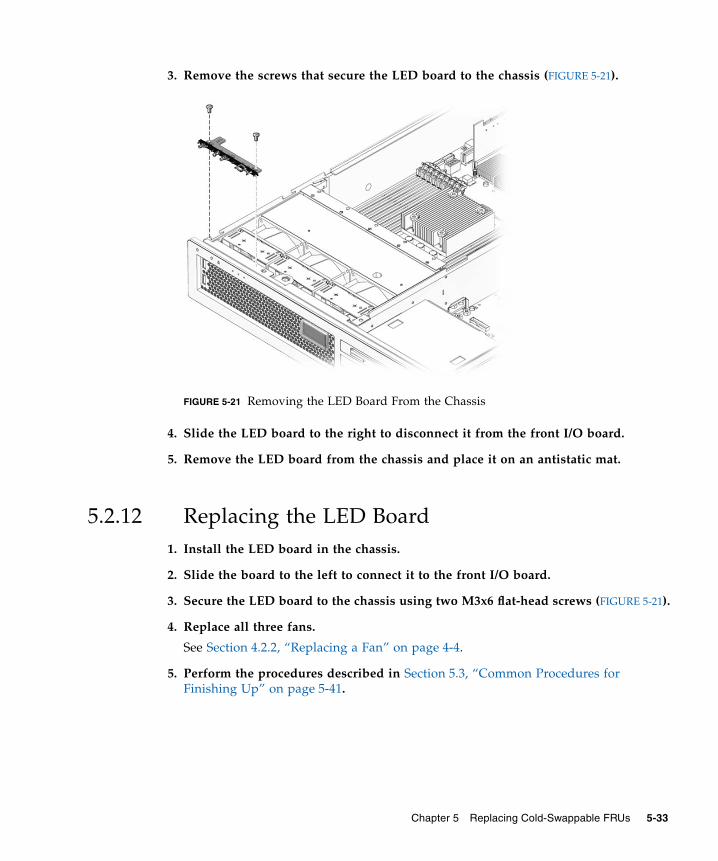
3. Remove the screws that secure the LED board to the chassis (FIGURE 5-21).
FIGURE 5-21 Removing the LED Board From the Chassis
4. Slide the LED board to the right to disconnect it from the front I/O board.
5. Remove the LED board from the chassis and place it on an antistatic mat.
5.2.12 Replacing the LED Board1. Install the LED board in the chassis.
2. Slide the board to the left to connect it to the front I/O board.
3. Secure the LED board to the chassis using two M3x6 flat-head screws (FIGURE 5-21).
4. Replace all three fans.
See Section 4.2.2, “Replacing a Fan” on page 4-4.
5. Perform the procedures described in Section 5.3, “Common Procedures forFinishing Up” on page 5-41.
Chapter 5 Replacing Cold-Swappable FRUs 5-33
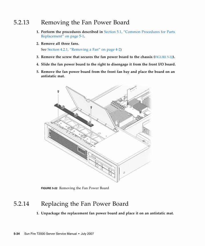
5.2.13 Removing the Fan Power Board1. Perform the procedures described in Section 5.1, “Common Procedures for Parts
Replacement” on page 5-1.
2. Remove all three fans.
See Section 4.2.1, “Removing a Fan” on page 4-2)
3. Remove the screw that secures the fan power board to the chassis (FIGURE 5-22).
4. Slide the fan power board to the right to disengage it from the front I/O board.
5. Remove the fan power board from the front fan bay and place the board on anantistatic mat.
FIGURE 5-22 Removing the Fan Power Board
5.2.14 Replacing the Fan Power Board1. Unpackage the replacement fan power board and place it on an antistatic mat.
5-34 Sun Fire T2000 Server Service Manual • July 2007
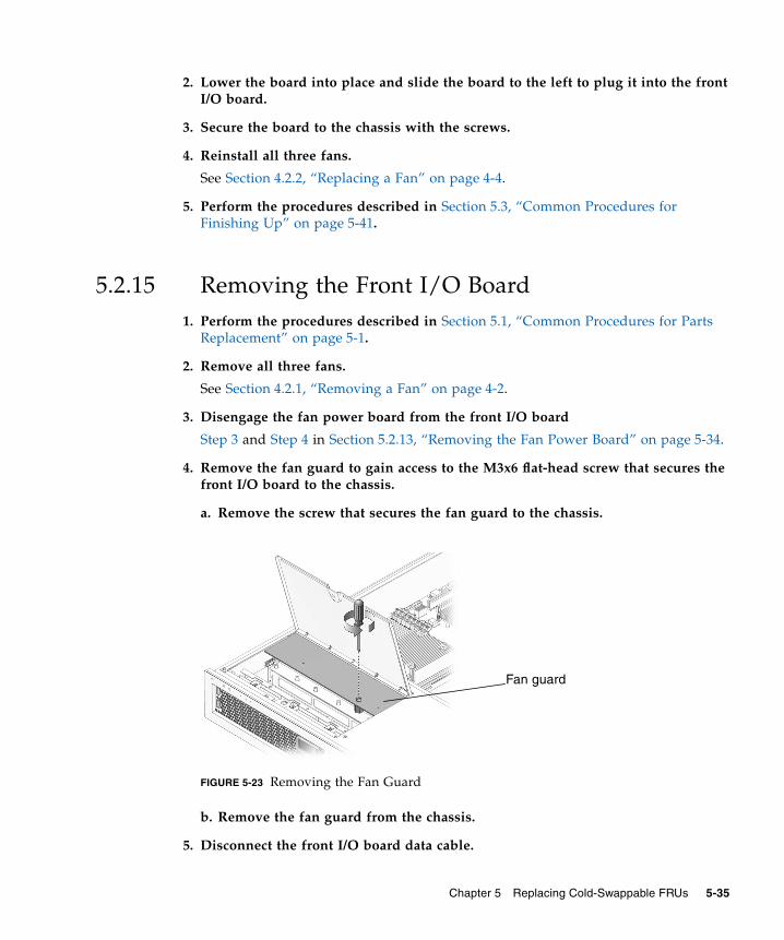
2. Lower the board into place and slide the board to the left to plug it into the frontI/O board.
3. Secure the board to the chassis with the screws.
4. Reinstall all three fans.
See Section 4.2.2, “Replacing a Fan” on page 4-4.
5. Perform the procedures described in Section 5.3, “Common Procedures forFinishing Up” on page 5-41.
5.2.15 Removing the Front I/O Board1. Perform the procedures described in Section 5.1, “Common Procedures for Parts
Replacement” on page 5-1.
2. Remove all three fans.
See Section 4.2.1, “Removing a Fan” on page 4-2.
3. Disengage the fan power board from the front I/O board
Step 3 and Step 4 in Section 5.2.13, “Removing the Fan Power Board” on page 5-34.
4. Remove the fan guard to gain access to the M3x6 flat-head screw that secures thefront I/O board to the chassis.
a. Remove the screw that secures the fan guard to the chassis.
FIGURE 5-23 Removing the Fan Guard
b. Remove the fan guard from the chassis.
5. Disconnect the front I/O board data cable.
Fan guard
Chapter 5 Replacing Cold-Swappable FRUs 5-35
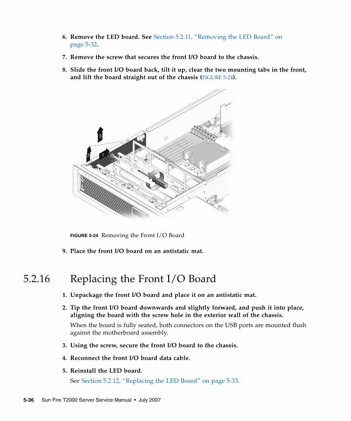
6. Remove the LED board. See Section 5.2.11, “Removing the LED Board” onpage 5-32.
7. Remove the screw that secures the front I/O board to the chassis.
8. Slide the front I/O board back, tilt it up, clear the two mounting tabs in the front,and lift the board straight out of the chassis (FIGURE 5-24).
FIGURE 5-24 Removing the Front I/O Board
9. Place the front I/O board on an antistatic mat.
5.2.16 Replacing the Front I/O Board1. Unpackage the front I/O board and place it on an antistatic mat.
2. Tip the front I/O board downwards and slightly forward, and push it into place,aligning the board with the screw hole in the exterior wall of the chassis.
When the board is fully seated, both connectors on the USB ports are mounted flushagainst the motherboard assembly.
3. Using the screw, secure the front I/O board to the chassis.
4. Reconnect the front I/O board data cable.
5. Reinstall the LED board.
See Section 5.2.12, “Replacing the LED Board” on page 5-33.
5-36 Sun Fire T2000 Server Service Manual • July 2007
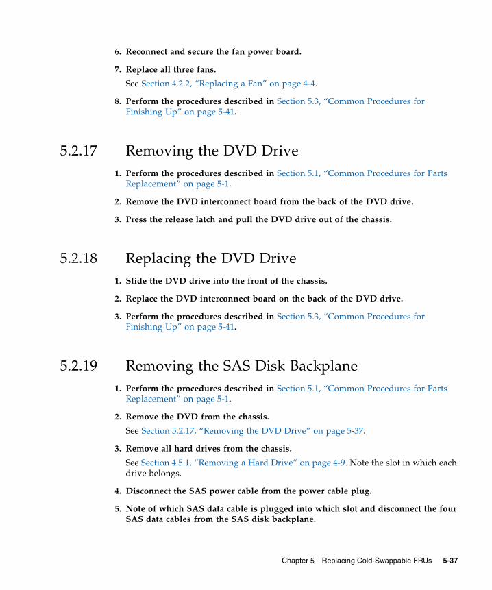
6. Reconnect and secure the fan power board.
7. Replace all three fans.
See Section 4.2.2, “Replacing a Fan” on page 4-4.
8. Perform the procedures described in Section 5.3, “Common Procedures forFinishing Up” on page 5-41.
5.2.17 Removing the DVD Drive1. Perform the procedures described in Section 5.1, “Common Procedures for Parts
Replacement” on page 5-1.
2. Remove the DVD interconnect board from the back of the DVD drive.
3. Press the release latch and pull the DVD drive out of the chassis.
5.2.18 Replacing the DVD Drive1. Slide the DVD drive into the front of the chassis.
2. Replace the DVD interconnect board on the back of the DVD drive.
3. Perform the procedures described in Section 5.3, “Common Procedures forFinishing Up” on page 5-41.
5.2.19 Removing the SAS Disk Backplane1. Perform the procedures described in Section 5.1, “Common Procedures for Parts
Replacement” on page 5-1.
2. Remove the DVD from the chassis.
See Section 5.2.17, “Removing the DVD Drive” on page 5-37.
3. Remove all hard drives from the chassis.
See Section 4.5.1, “Removing a Hard Drive” on page 4-9. Note the slot in which eachdrive belongs.
4. Disconnect the SAS power cable from the power cable plug.
5. Note of which SAS data cable is plugged into which slot and disconnect the fourSAS data cables from the SAS disk backplane.
Chapter 5 Replacing Cold-Swappable FRUs 5-37
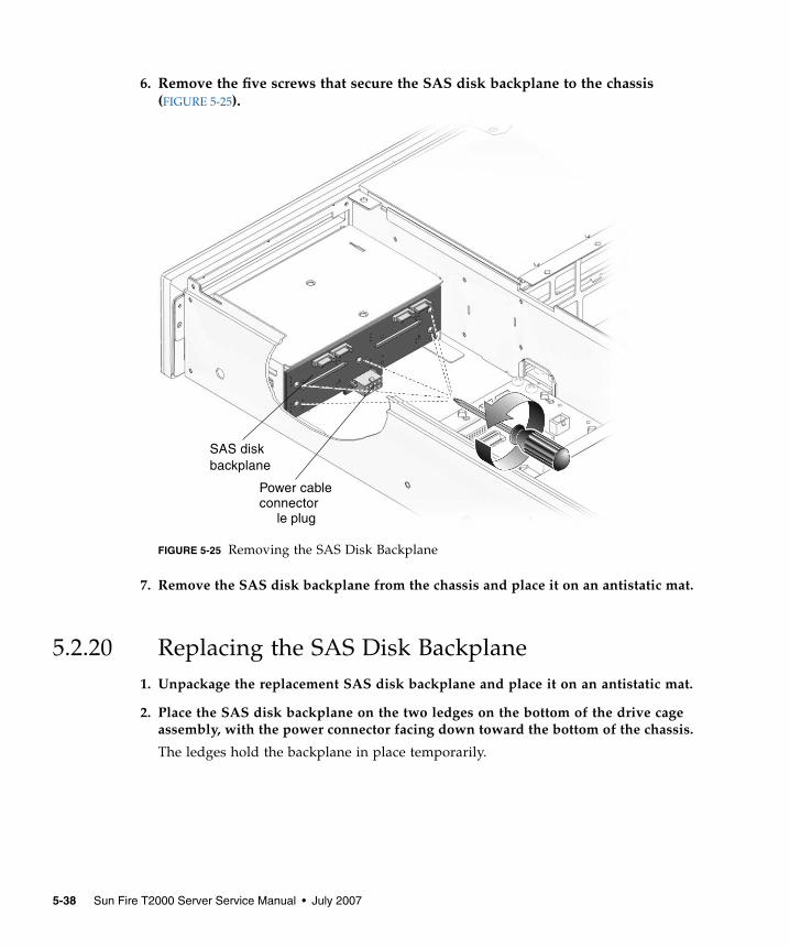
6. Remove the five screws that secure the SAS disk backplane to the chassis(FIGURE 5-25).
FIGURE 5-25 Removing the SAS Disk Backplane
7. Remove the SAS disk backplane from the chassis and place it on an antistatic mat.
5.2.20 Replacing the SAS Disk Backplane1. Unpackage the replacement SAS disk backplane and place it on an antistatic mat.
2. Place the SAS disk backplane on the two ledges on the bottom of the drive cageassembly, with the power connector facing down toward the bottom of the chassis.
The ledges hold the backplane in place temporarily.
SAS diskbackplane
Power cable
le plugconnector
5-38 Sun Fire T2000 Server Service Manual • July 2007
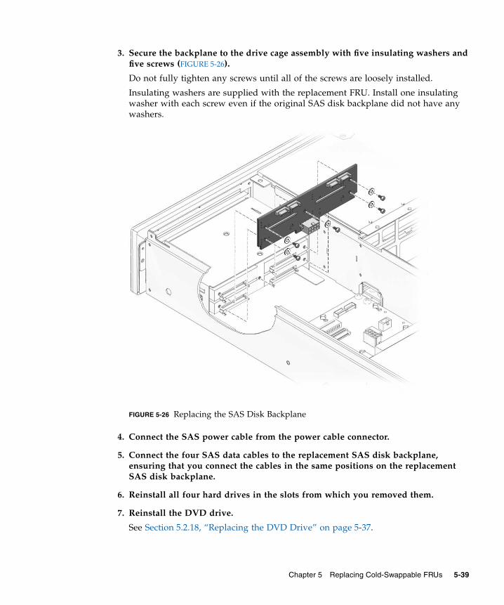
3. Secure the backplane to the drive cage assembly with five insulating washers andfive screws (FIGURE 5-26).
Do not fully tighten any screws until all of the screws are loosely installed.
Insulating washers are supplied with the replacement FRU. Install one insulatingwasher with each screw even if the original SAS disk backplane did not have anywashers.
FIGURE 5-26 Replacing the SAS Disk Backplane
4. Connect the SAS power cable from the power cable connector.
5. Connect the four SAS data cables to the replacement SAS disk backplane,ensuring that you connect the cables in the same positions on the replacementSAS disk backplane.
6. Reinstall all four hard drives in the slots from which you removed them.
7. Reinstall the DVD drive.
See Section 5.2.18, “Replacing the DVD Drive” on page 5-37.
Chapter 5 Replacing Cold-Swappable FRUs 5-39
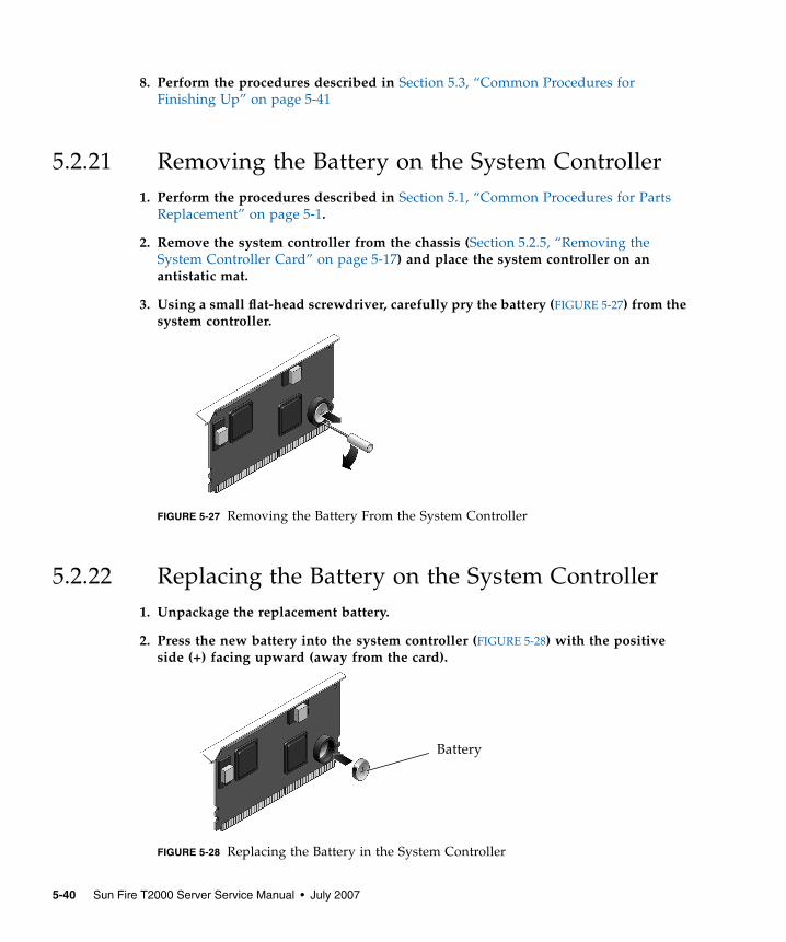
8. Perform the procedures described in Section 5.3, “Common Procedures forFinishing Up” on page 5-41
5.2.21 Removing the Battery on the System Controller1. Perform the procedures described in Section 5.1, “Common Procedures for Parts
Replacement” on page 5-1.
2. Remove the system controller from the chassis (Section 5.2.5, “Removing theSystem Controller Card” on page 5-17) and place the system controller on anantistatic mat.
3. Using a small flat-head screwdriver, carefully pry the battery (FIGURE 5-27) from thesystem controller.
FIGURE 5-27 Removing the Battery From the System Controller
5.2.22 Replacing the Battery on the System Controller1. Unpackage the replacement battery.
2. Press the new battery into the system controller (FIGURE 5-28) with the positiveside (+) facing upward (away from the card).
FIGURE 5-28 Replacing the Battery in the System Controller
Battery
5-40 Sun Fire T2000 Server Service Manual • July 2007
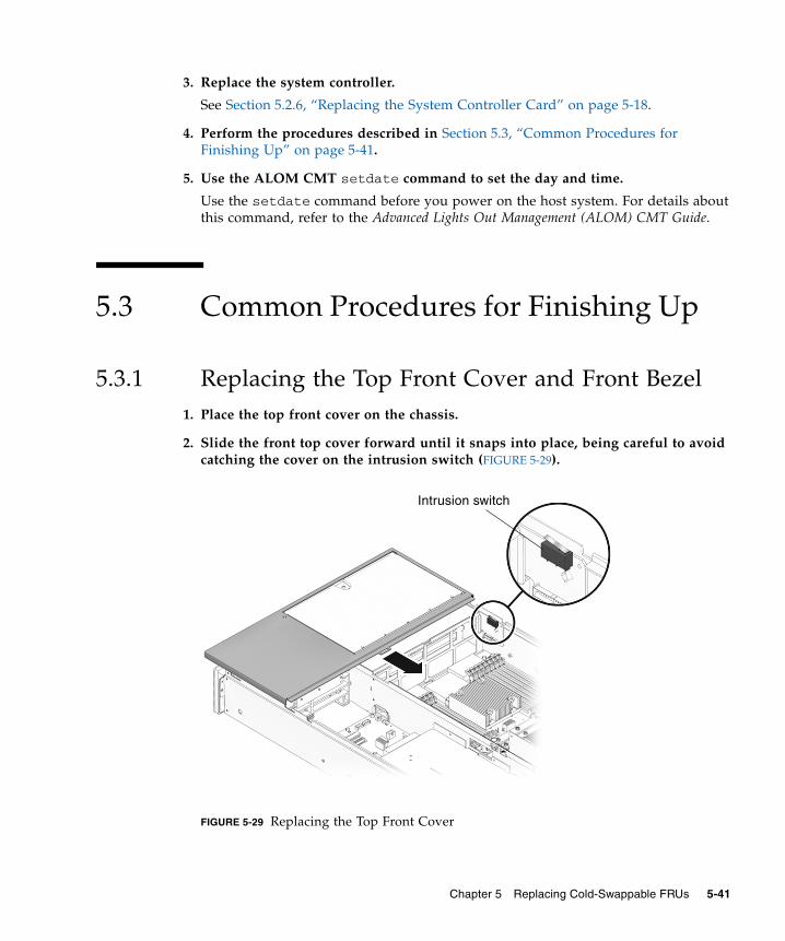
3. Replace the system controller.
See Section 5.2.6, “Replacing the System Controller Card” on page 5-18.
4. Perform the procedures described in Section 5.3, “Common Procedures forFinishing Up” on page 5-41.
5. Use the ALOM CMT setdate command to set the day and time.
Use the setdate command before you power on the host system. For details aboutthis command, refer to the Advanced Lights Out Management (ALOM) CMT Guide.
5.3 Common Procedures for Finishing Up
5.3.1 Replacing the Top Front Cover and Front Bezel1. Place the top front cover on the chassis.
2. Slide the front top cover forward until it snaps into place, being careful to avoidcatching the cover on the intrusion switch (FIGURE 5-29).
FIGURE 5-29 Replacing the Top Front Cover
Intrusion switch
Chapter 5 Replacing Cold-Swappable FRUs 5-41
3. Position the bezel on the front of the chassis and snap it into place.
4. Open the fan door.
5. Tighten the captive screw to secure the front bezel to the chassis.
5.3.2 Replacing the Top Cover1. Place the top cover on the chassis.
Set the cover down so that it hangs over the rear of the server by about an inch.
2. Slide the cover forward until it latches into place.
5.3.3 Reinstalling the Server Chassis in the RackIf you removed the server chassis from the rack, perform these steps.
Caution – The server weighs approximately 40 lb. (18 kg). Two people are requiredto carry the chassis and install it in the rack.
1. Ensure that the rack rails are extended.
2. Place the ends of the chassis mounting brackets (inner section) into the slide rails(FIGURE 5-30).
5-42 Sun Fire T2000 Server Service Manual • July 2007
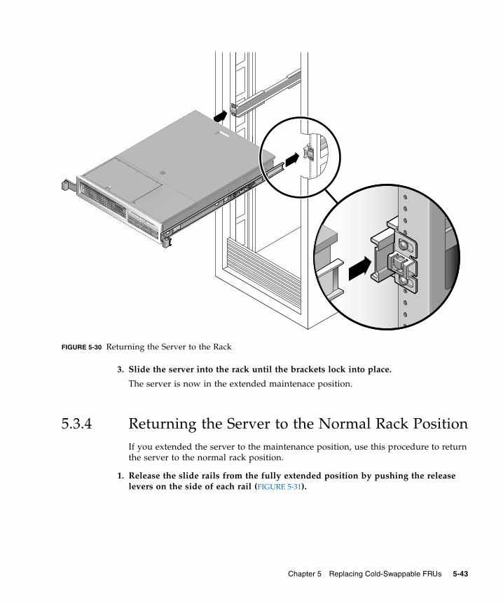
FIGURE 5-30 Returning the Server to the Rack
3. Slide the server into the rack until the brackets lock into place.
The server is now in the extended maintenace position.
5.3.4 Returning the Server to the Normal Rack PositionIf you extended the server to the maintenance position, use this procedure to returnthe server to the normal rack position.
1. Release the slide rails from the fully extended position by pushing the releaselevers on the side of each rail (FIGURE 5-31).
Chapter 5 Replacing Cold-Swappable FRUs 5-43
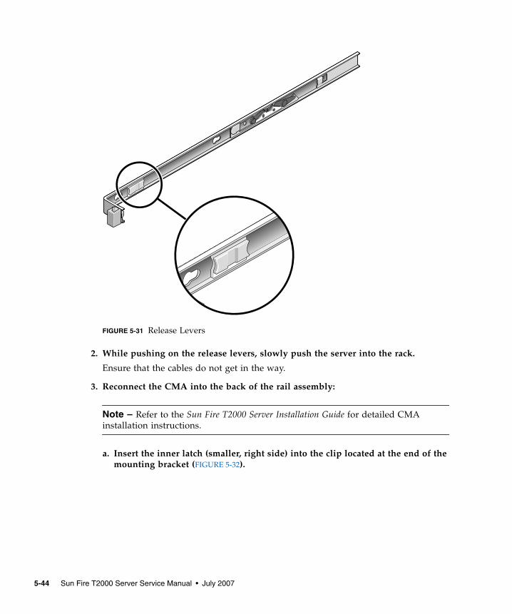
FIGURE 5-31 Release Levers
2. While pushing on the release levers, slowly push the server into the rack.
Ensure that the cables do not get in the way.
3. Reconnect the CMA into the back of the rail assembly:
Note – Refer to the Sun Fire T2000 Server Installation Guide for detailed CMAinstallation instructions.
a. Insert the inner latch (smaller, right side) into the clip located at the end of themounting bracket (FIGURE 5-32).
5-44 Sun Fire T2000 Server Service Manual • July 2007
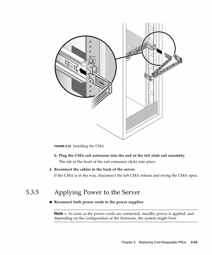
FIGURE 5-32 Installing the CMA
b. Plug the CMA rail extension into the end of the left slide rail assembly.
The tab at the front of the rail extension clicks into place.
4. Reconnect the cables to the back of the server.
If the CMA is in the way, disconnect the left CMA release and swing the CMA open.
5.3.5 Applying Power to the Server● Reconnect both power cords to the power supplies.
Note – As soon as the power cords are connected, standby power is applied, anddepending on the configuration of the firmware, the system might boot.
Chapter 5 Replacing Cold-Swappable FRUs 5-45

5-46 Sun Fire T2000 Server Service Manual • July 2007
CHAPTER 6
Adding New Components andDevices
This chapter describes how to add new components and devices to the server.
The following topics are covered:
■ Section 6.1, “Adding Hot-Pluggable and Hot-Swappable Devices” on page 6-1■ Section 6.2, “Adding Components Inside the Chassis” on page 6-4
6.1 Adding Hot-Pluggable and Hot-Swappable DevicesHot-pluggable devices, such as hard drives, require administration duringinstallation.
Hot-swappable devices, such as USB devices, can be connected to, and disconnectedfrom, the system while the system is running.
Other components and devices require you to shut down the system prior toinstallation. See Section 6.2, “Adding Components Inside the Chassis” on page 6-4.
6.1.1 Adding a Hard Drive to the ServerHard drives are physically addressed according to the slot in which they areinstalled. Depending on the server model, the hard drives might be connected to aPCI-X SAS controller card, or connected to a drive controller that is built into the
6-1
motherboard (an onboard hard drive controller). Regardless of the type of controller,the hard drives are installed into the chassis the same way as described in thisprocedure.
Note – Not all servers have the on-board hard drive controller support. Theseservers have the PCI-X SAS controller card installed.
1. Remove the blank panel from the chassis:
a. On the blank panel, push the latch release button.
b. Grasp the latch and pull the blank panel out.
2. Align the disk drive to the drive bay slot.
See FIGURE 6-1. For additional details, see Section 4.5.1, “Removing a Hard Drive” onpage 4-9.
3. Slide the hard drive into the bay until the drive is fully seated.
4. Close the hard drive lever to lock the drive in place.
5. Use cfgadm -al to list all disks in the device tree, including unconfigured disks.
If the disk is not in list, such as with a newly installed disk, then use devfsadm toconfigure it into the tree. See the devfsadm man page for details.
6-2 Sun Fire T2000 Server Service Manual • July 2007
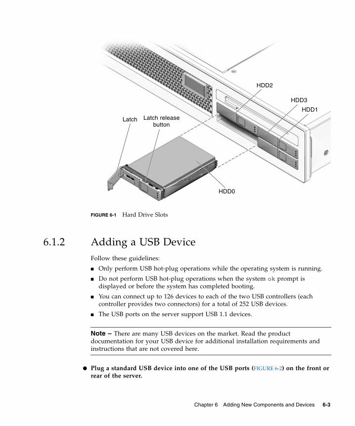
FIGURE 6-1 Hard Drive Slots
6.1.2 Adding a USB DeviceFollow these guidelines:
■ Only perform USB hot-plug operations while the operating system is running.
■ Do not perform USB hot-plug operations when the system ok prompt isdisplayed or before the system has completed booting.
■ You can connect up to 126 devices to each of the two USB controllers (eachcontroller provides two connectors) for a total of 252 USB devices.
■ The USB ports on the server support USB 1.1 devices.
Note – There are many USB devices on the market. Read the productdocumentation for your USB device for additional installation requirements andinstructions that are not covered here.
● Plug a standard USB device into one of the USB ports (FIGURE 6-2) on the front orrear of the server.
Latch releaseLatch
HDD3
HDD1
HDD2
button
HDD0
Chapter 6 Adding New Components and Devices 6-3
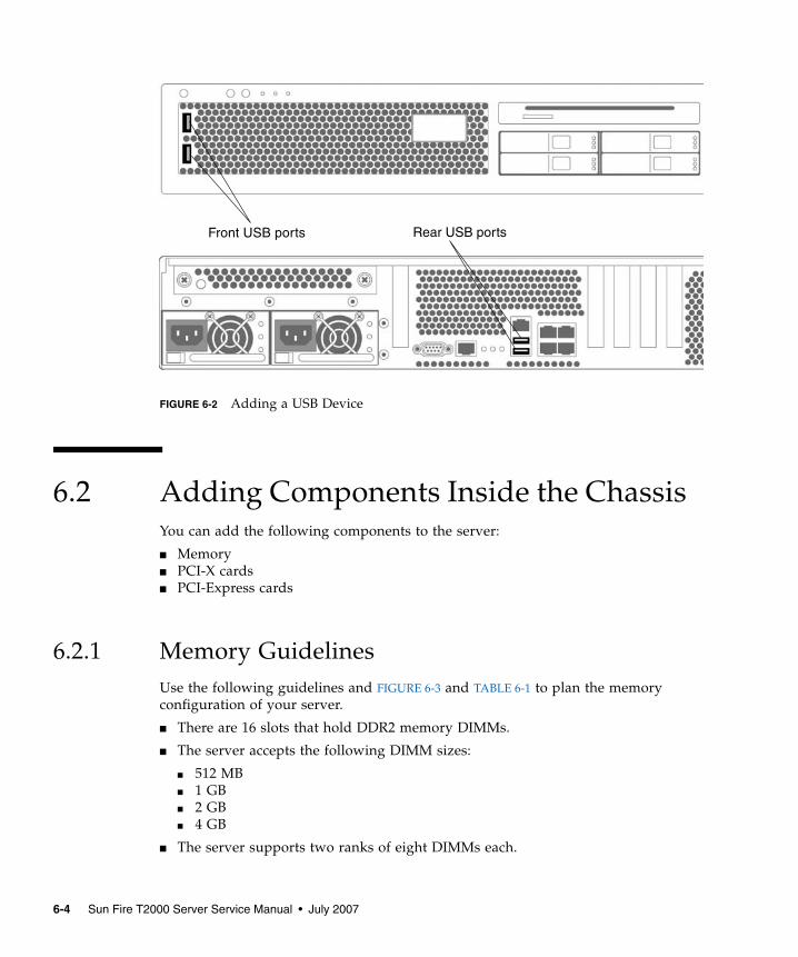
FIGURE 6-2 Adding a USB Device
6.2 Adding Components Inside the ChassisYou can add the following components to the server:
■ Memory■ PCI-X cards■ PCI-Express cards
6.2.1 Memory GuidelinesUse the following guidelines and FIGURE 6-3 and TABLE 6-1 to plan the memoryconfiguration of your server.
■ There are 16 slots that hold DDR2 memory DIMMs.
■ The server accepts the following DIMM sizes:
■ 512 MB■ 1 GB■ 2 GB■ 4 GB
■ The server supports two ranks of eight DIMMs each.
Front USB ports Rear USB ports
6-4 Sun Fire T2000 Server Service Manual • July 2007
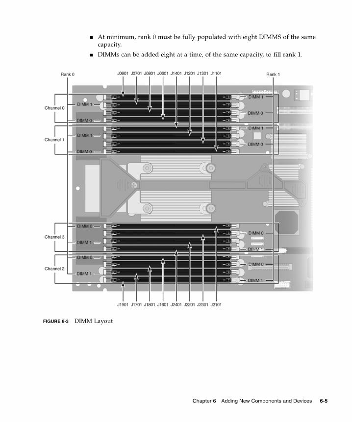
■ At minimum, rank 0 must be fully populated with eight DIMMS of the samecapacity.
■ DIMMs can be added eight at a time, of the same capacity, to fill rank 1.
FIGURE 6-3 DIMM Layout
Front ofboard
Chapter 6 Adding New Components and Devices 6-5
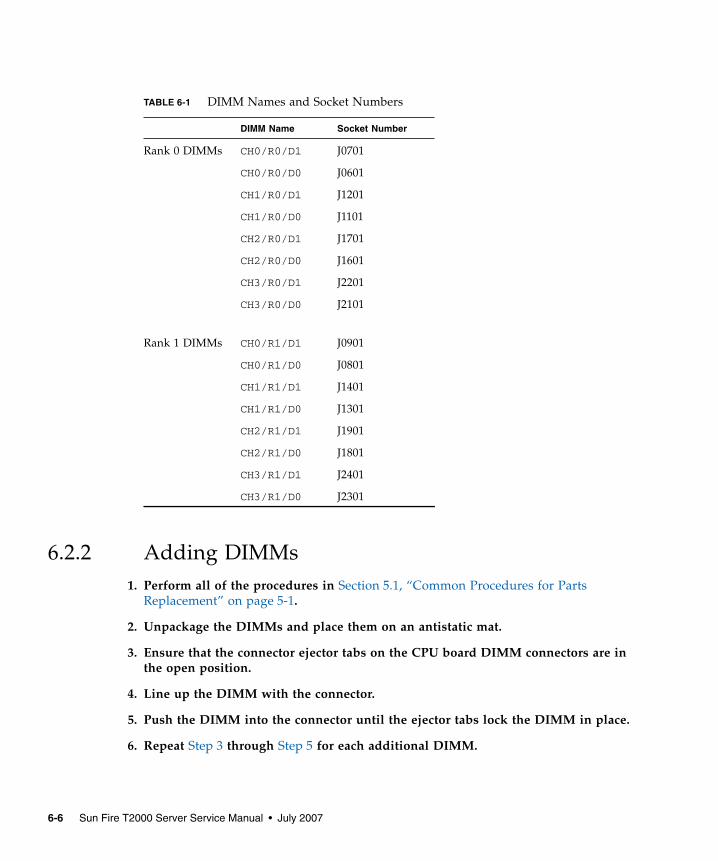
6.2.2 Adding DIMMs1. Perform all of the procedures in Section 5.1, “Common Procedures for Parts
Replacement” on page 5-1.
2. Unpackage the DIMMs and place them on an antistatic mat.
3. Ensure that the connector ejector tabs on the CPU board DIMM connectors are inthe open position.
4. Line up the DIMM with the connector.
5. Push the DIMM into the connector until the ejector tabs lock the DIMM in place.
6. Repeat Step 3 through Step 5 for each additional DIMM.
TABLE 6-1 DIMM Names and Socket Numbers
DIMM Name Socket Number
Rank 0 DIMMs CH0/R0/D1 J0701
CH0/R0/D0 J0601
CH1/R0/D1 J1201
CH1/R0/D0 J1101
CH2/R0/D1 J1701
CH2/R0/D0 J1601
CH3/R0/D1 J2201
CH3/R0/D0 J2101
Rank 1 DIMMs CH0/R1/D1 J0901
CH0/R1/D0 J0801
CH1/R1/D1 J1401
CH1/R1/D0 J1301
CH2/R1/D1 J1901
CH2/R1/D0 J1801
CH3/R1/D1 J2401
CH3/R1/D0 J2301
6-6 Sun Fire T2000 Server Service Manual • July 2007
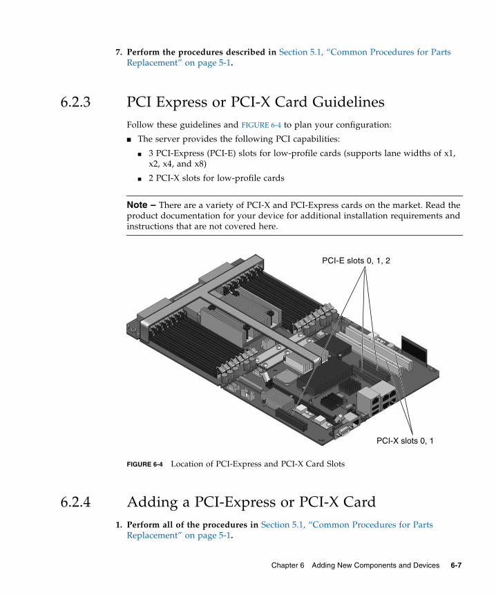
7. Perform the procedures described in Section 5.1, “Common Procedures for PartsReplacement” on page 5-1.
6.2.3 PCI Express or PCI-X Card GuidelinesFollow these guidelines and FIGURE 6-4 to plan your configuration:
■ The server provides the following PCI capabilities:
■ 3 PCI-Express (PCI-E) slots for low-profile cards (supports lane widths of x1,x2, x4, and x8)
■ 2 PCI-X slots for low-profile cards
Note – There are a variety of PCI-X and PCI-Express cards on the market. Read theproduct documentation for your device for additional installation requirements andinstructions that are not covered here.
FIGURE 6-4 Location of PCI-Express and PCI-X Card Slots
6.2.4 Adding a PCI-Express or PCI-X Card1. Perform all of the procedures in Section 5.1, “Common Procedures for Parts
Replacement” on page 5-1.
PCI-E slots 0, 1, 2
PCI-X slots 0, 1
Chapter 6 Adding New Components and Devices 6-7
2. Rotate the PCI hold-down bracket (located on the edge of the chassis) 90 degreesso that the chassis edge can accept the card.
You might need to loosen the screw that holds the bracket to the chassis.
3. Line up the PCI card with the PCI connector on the rear of the motherboard.
4. Push the card into the connector so it is fully seated.
5. Rotate the PCI hold-down bracket to the closed position and secure the screw onthe bracket.
6. Install any cables that go to the PCI card.
7. Perform the procedures described in Section 5.1, “Common Procedures for PartsReplacement” on page 5-1.
6-8 Sun Fire T2000 Server Service Manual • July 2007
APPENDIX A
Field-Replaceable Units
This appendix provides illustrated parts breakdown diagrams and a table that liststhe server FRUs.
The following topic is covered:
■ Section A.1, “Illustrated FRU Locations” on page A-2
A-1
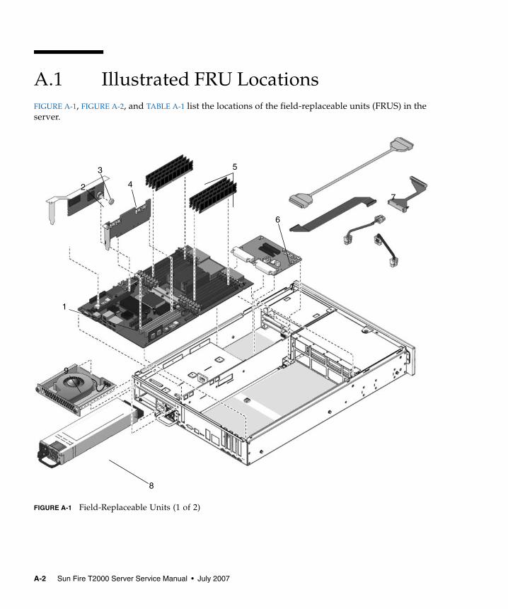
A.1 Illustrated FRU LocationsFIGURE A-1, FIGURE A-2, and TABLE A-1 list the locations of the field-replaceable units (FRUS) in theserver.
FIGURE A-1 Field-Replaceable Units (1 of 2)
1
5
2
6
8
9
3
4
7
A-2 Sun Fire T2000 Server Service Manual • July 2007
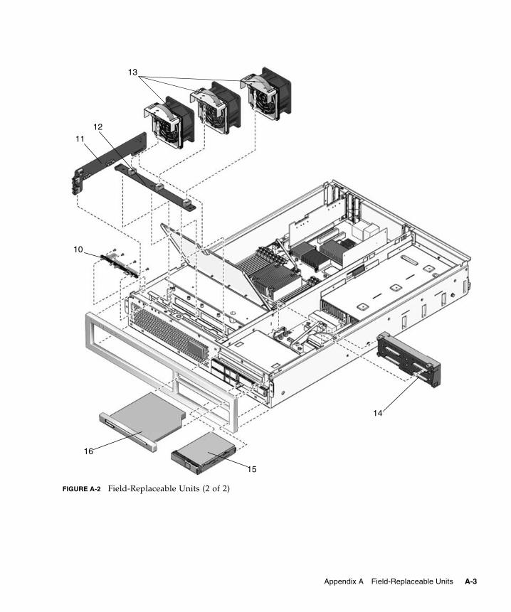
FIGURE A-2 Field-Replaceable Units (2 of 2)
13
1112
10
14
16
15
Appendix A Field-Replaceable Units A-3
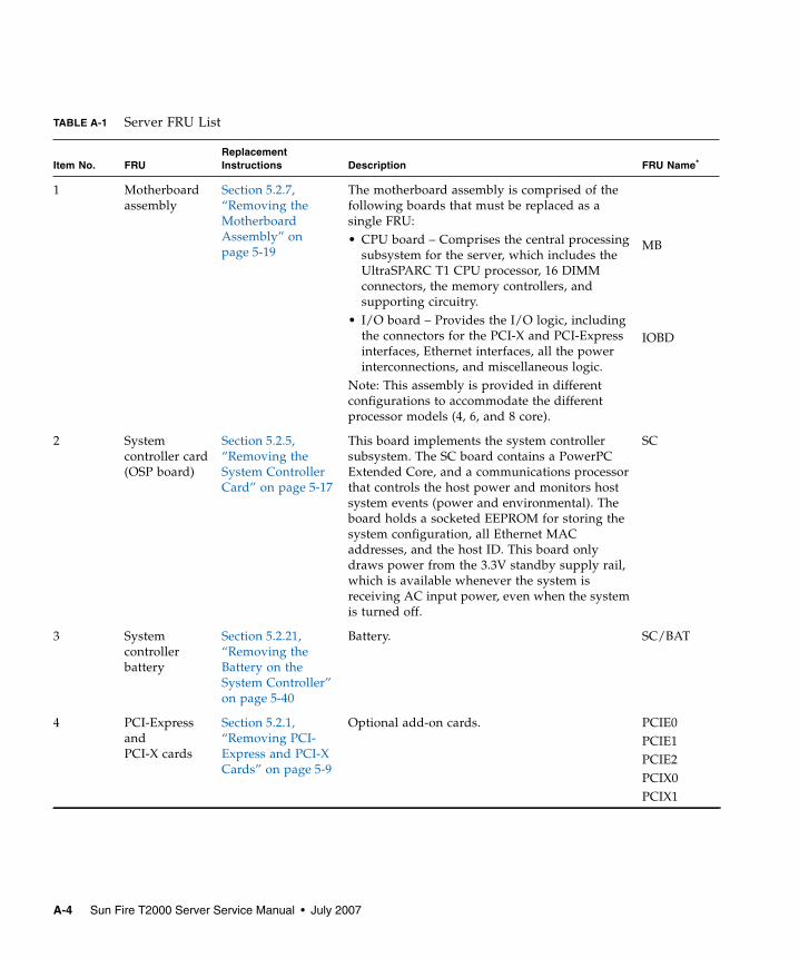
TABLE A-1 Server FRU List
Item No. FRUReplacementInstructions Description FRU Name*
1 Motherboardassembly
Section 5.2.7,“Removing theMotherboardAssembly” onpage 5-19
The motherboard assembly is comprised of thefollowing boards that must be replaced as asingle FRU:• CPU board – Comprises the central processing
subsystem for the server, which includes theUltraSPARC T1 CPU processor, 16 DIMMconnectors, the memory controllers, andsupporting circuitry.
• I/O board – Provides the I/O logic, includingthe connectors for the PCI-X and PCI-Expressinterfaces, Ethernet interfaces, all the powerinterconnections, and miscellaneous logic.
Note: This assembly is provided in differentconfigurations to accommodate the differentprocessor models (4, 6, and 8 core).
MB
IOBD
2 Systemcontroller card(OSP board)
Section 5.2.5,“Removing theSystem ControllerCard” on page 5-17
This board implements the system controllersubsystem. The SC board contains a PowerPCExtended Core, and a communications processorthat controls the host power and monitors hostsystem events (power and environmental). Theboard holds a socketed EEPROM for storing thesystem configuration, all Ethernet MACaddresses, and the host ID. This board onlydraws power from the 3.3V standby supply rail,which is available whenever the system isreceiving AC input power, even when the systemis turned off.
SC
3 Systemcontrollerbattery
Section 5.2.21,“Removing theBattery on theSystem Controller”on page 5-40
Battery. SC/BAT
4 PCI-ExpressandPCI-X cards
Section 5.2.1,“Removing PCI-Express and PCI-XCards” on page 5-9
Optional add-on cards. PCIE0PCIE1PCIE2PCIX0PCIX1
A-4 Sun Fire T2000 Server Service Manual • July 2007
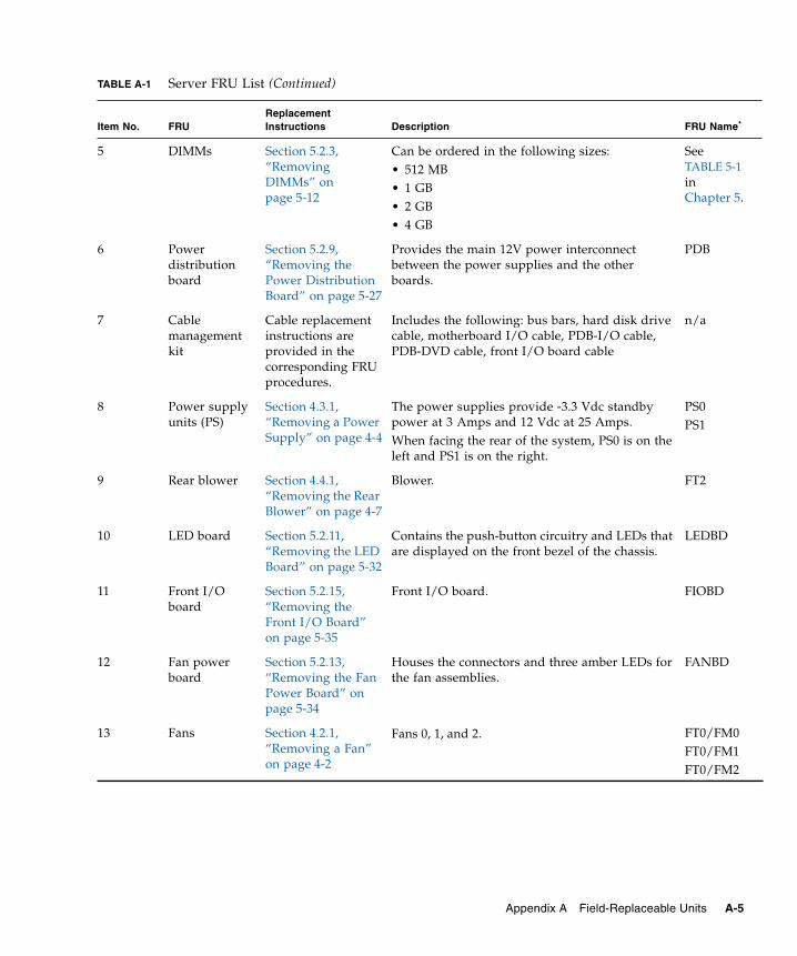
5 DIMMs Section 5.2.3,“RemovingDIMMs” onpage 5-12
Can be ordered in the following sizes:• 512 MB• 1 GB• 2 GB• 4 GB
SeeTABLE 5-1inChapter 5.
6 Powerdistributionboard
Section 5.2.9,“Removing thePower DistributionBoard” on page 5-27
Provides the main 12V power interconnectbetween the power supplies and the otherboards.
PDB
7 Cablemanagementkit
Cable replacementinstructions areprovided in thecorresponding FRUprocedures.
Includes the following: bus bars, hard disk drivecable, motherboard I/O cable, PDB-I/O cable,PDB-DVD cable, front I/O board cable
n/a
8 Power supplyunits (PS)
Section 4.3.1,“Removing a PowerSupply” on page 4-4
The power supplies provide -3.3 Vdc standbypower at 3 Amps and 12 Vdc at 25 Amps.When facing the rear of the system, PS0 is on theleft and PS1 is on the right.
PS0PS1
9 Rear blower Section 4.4.1,“Removing the RearBlower” on page 4-7
Blower. FT2
10 LED board Section 5.2.11,“Removing the LEDBoard” on page 5-32
Contains the push-button circuitry and LEDs thatare displayed on the front bezel of the chassis.
LEDBD
11 Front I/Oboard
Section 5.2.15,“Removing theFront I/O Board”on page 5-35
Front I/O board. FIOBD
12 Fan powerboard
Section 5.2.13,“Removing the FanPower Board” onpage 5-34
Houses the connectors and three amber LEDs forthe fan assemblies.
FANBD
13 Fans Section 4.2.1,“Removing a Fan”on page 4-2
Fans 0, 1, and 2. FT0/FM0FT0/FM1FT0/FM2
TABLE A-1 Server FRU List (Continued)
Item No. FRUReplacementInstructions Description FRU Name*
Appendix A Field-Replaceable Units A-5
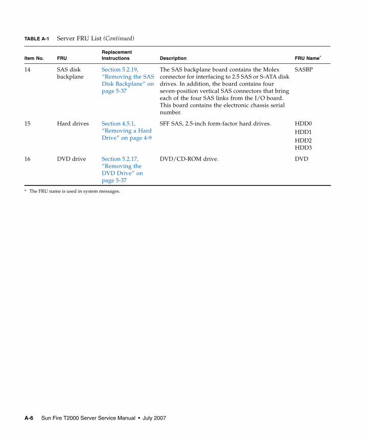
14 SAS diskbackplane
Section 5.2.19,“Removing the SASDisk Backplane” onpage 5-37
The SAS backplane board contains the Molexconnector for interfacing to 2.5 SAS or S-ATA diskdrives. In addition, the board contains fourseven-position vertical SAS connectors that bringeach of the four SAS links from the I/O board.This board contains the electronic chassis serialnumber.
SASBP
15 Hard drives Section 4.5.1,“Removing a HardDrive” on page 4-9
SFF SAS, 2.5-inch form-factor hard drives. HDD0HDD1HDD2HDD3
16 DVD drive Section 5.2.17,“Removing theDVD Drive” onpage 5-37
DVD/CD-ROM drive. DVD
* The FRU name is used in system messages.
TABLE A-1 Server FRU List (Continued)
Item No. FRUReplacementInstructions Description FRU Name*
A-6 Sun Fire T2000 Server Service Manual • July 2007
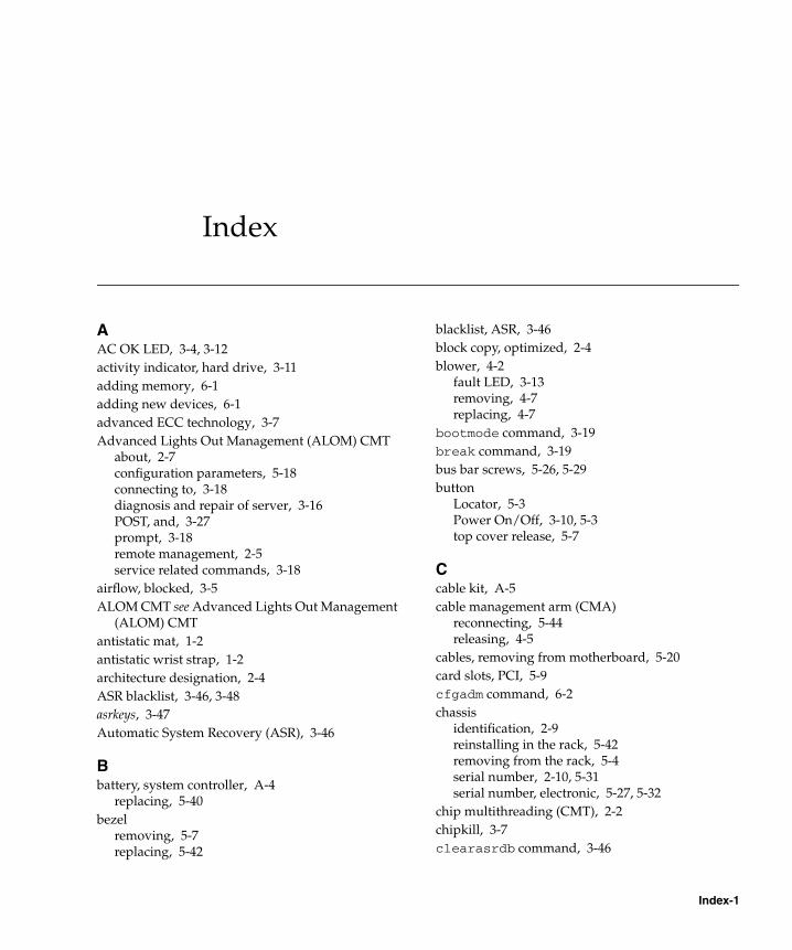
Index
AAC OK LED, 3-4, 3-12activity indicator, hard drive, 3-11adding memory, 6-1adding new devices, 6-1advanced ECC technology, 3-7Advanced Lights Out Management (ALOM) CMT
about, 2-7configuration parameters, 5-18connecting to, 3-18diagnosis and repair of server, 3-16POST, and, 3-27prompt, 3-18remote management, 2-5service related commands, 3-18
airflow, blocked, 3-5ALOM CMT see Advanced Lights Out Management
(ALOM) CMTantistatic mat, 1-2antistatic wrist strap, 1-2architecture designation, 2-4ASR blacklist, 3-46, 3-48asrkeys, 3-47Automatic System Recovery (ASR), 3-46
Bbattery, system controller, A-4
replacing, 5-40bezel
removing, 5-7replacing, 5-42
blacklist, ASR, 3-46block copy, optimized, 2-4blower, 4-2
fault LED, 3-13removing, 4-7replacing, 4-7
bootmode command, 3-19break command, 3-19bus bar screws, 5-26, 5-29button
Locator, 5-3Power On/Off, 3-10, 5-3top cover release, 5-7
Ccable kit, A-5cable management arm (CMA)
reconnecting, 5-44releasing, 4-5
cables, removing from motherboard, 5-20card slots, PCI, 5-9cfgadm command, 6-2chassis
identification, 2-9reinstalling in the rack, 5-42removing from the rack, 5-4serial number, 2-10, 5-31serial number, electronic, 5-27, 5-32
chip multithreading (CMT), 2-2chipkill, 3-7clearasrdb command, 3-46
Index-1
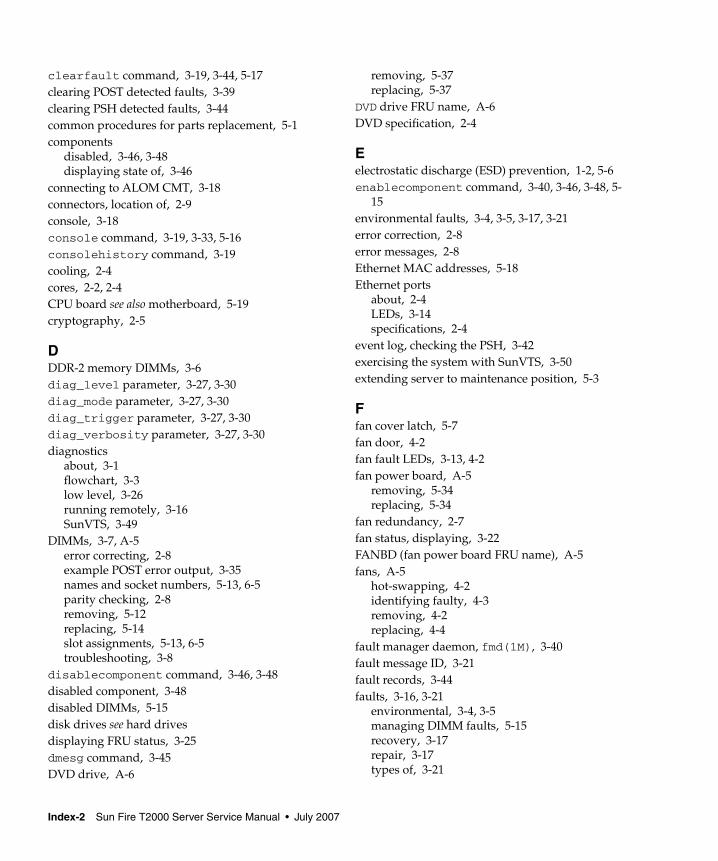
clearfault command, 3-19, 3-44, 5-17clearing POST detected faults, 3-39clearing PSH detected faults, 3-44common procedures for parts replacement, 5-1components
disabled, 3-46, 3-48displaying state of, 3-46
connecting to ALOM CMT, 3-18connectors, location of, 2-9console, 3-18console command, 3-19, 3-33, 5-16consolehistory command, 3-19cooling, 2-4cores, 2-2, 2-4CPU board see also motherboard, 5-19cryptography, 2-5
DDDR-2 memory DIMMs, 3-6diag_level parameter, 3-27, 3-30diag_mode parameter, 3-27, 3-30diag_trigger parameter, 3-27, 3-30diag_verbosity parameter, 3-27, 3-30diagnostics
about, 3-1flowchart, 3-3low level, 3-26running remotely, 3-16SunVTS, 3-49
DIMMs, 3-7, A-5error correcting, 2-8example POST error output, 3-35names and socket numbers, 5-13, 6-5parity checking, 2-8removing, 5-12replacing, 5-14slot assignments, 5-13, 6-5troubleshooting, 3-8
disablecomponent command, 3-46, 3-48disabled component, 3-48disabled DIMMs, 5-15disk drives see hard drivesdisplaying FRU status, 3-25dmesg command, 3-45DVD drive, A-6
removing, 5-37replacing, 5-37
DVD drive FRU name, A-6DVD specification, 2-4
Eelectrostatic discharge (ESD) prevention, 1-2, 5-6enablecomponent command, 3-40, 3-46, 3-48, 5-
15environmental faults, 3-4, 3-5, 3-17, 3-21error correction, 2-8error messages, 2-8Ethernet MAC addresses, 5-18Ethernet ports
about, 2-4LEDs, 3-14specifications, 2-4
event log, checking the PSH, 3-42exercising the system with SunVTS, 3-50extending server to maintenance position, 5-3
Ffan cover latch, 5-7fan door, 4-2fan fault LEDs, 3-13, 4-2fan power board, A-5
removing, 5-34replacing, 5-34
fan redundancy, 2-7fan status, displaying, 3-22FANBD (fan power board FRU name), A-5fans, A-5
hot-swapping, 4-2identifying faulty, 4-3removing, 4-2replacing, 4-4
fault manager daemon, fmd(1M), 3-40fault message ID, 3-21fault records, 3-44faults, 3-16, 3-21
environmental, 3-4, 3-5managing DIMM faults, 5-15recovery, 3-17repair, 3-17types of, 3-21
Index-2 Sun Fire T2000 Server Service Manual • July 2007
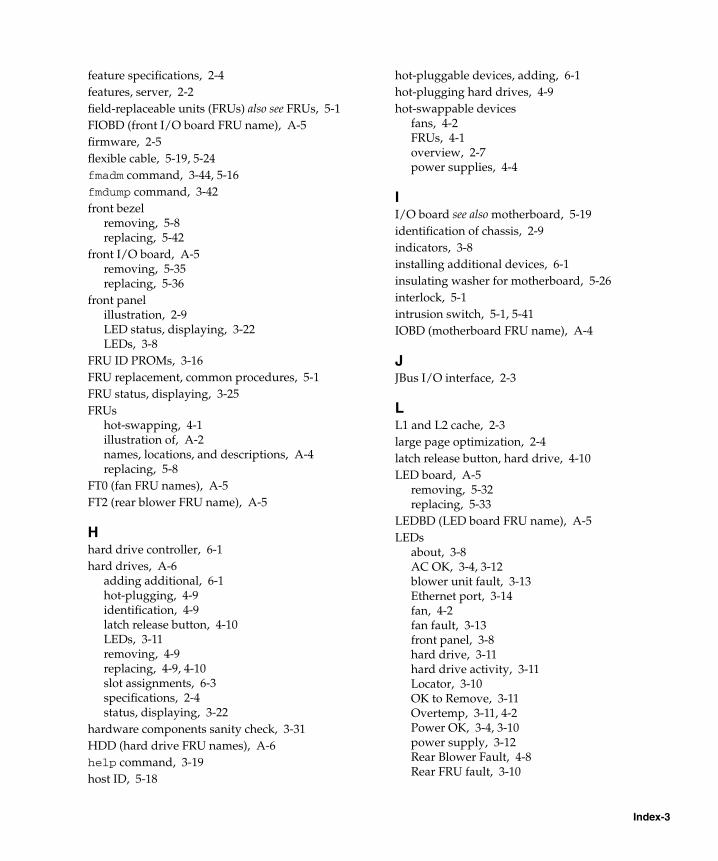
feature specifications, 2-4features, server, 2-2field-replaceable units (FRUs) also see FRUs, 5-1FIOBD (front I/O board FRU name), A-5firmware, 2-5flexible cable, 5-19, 5-24fmadm command, 3-44, 5-16fmdump command, 3-42front bezel
removing, 5-8replacing, 5-42
front I/O board, A-5removing, 5-35replacing, 5-36
front panelillustration, 2-9LED status, displaying, 3-22LEDs, 3-8
FRU ID PROMs, 3-16FRU replacement, common procedures, 5-1FRU status, displaying, 3-25FRUs
hot-swapping, 4-1illustration of, A-2names, locations, and descriptions, A-4replacing, 5-8
FT0 (fan FRU names), A-5FT2 (rear blower FRU name), A-5
Hhard drive controller, 6-1hard drives, A-6
adding additional, 6-1hot-plugging, 4-9identification, 4-9latch release button, 4-10LEDs, 3-11removing, 4-9replacing, 4-9, 4-10slot assignments, 6-3specifications, 2-4status, displaying, 3-22
hardware components sanity check, 3-31HDD (hard drive FRU names), A-6help command, 3-19host ID, 5-18
hot-pluggable devices, adding, 6-1hot-plugging hard drives, 4-9hot-swappable devices
fans, 4-2FRUs, 4-1overview, 2-7power supplies, 4-4
II/O board see also motherboard, 5-19identification of chassis, 2-9indicators, 3-8installing additional devices, 6-1insulating washer for motherboard, 5-26interlock, 5-1intrusion switch, 5-1, 5-41IOBD (motherboard FRU name), A-4
JJBus I/O interface, 2-3
LL1 and L2 cache, 2-3large page optimization, 2-4latch release button, hard drive, 4-10LED board, A-5
removing, 5-32replacing, 5-33
LEDBD (LED board FRU name), A-5LEDs
about, 3-8AC OK, 3-4, 3-12blower unit fault, 3-13Ethernet port, 3-14fan, 4-2fan fault, 3-13front panel, 3-8hard drive, 3-11hard drive activity, 3-11Locator, 3-10OK to Remove, 3-11Overtemp, 3-11, 4-2Power OK, 3-4, 3-10power supply, 3-12Rear Blower Fault, 4-8Rear FRU fault, 3-10
Index-3
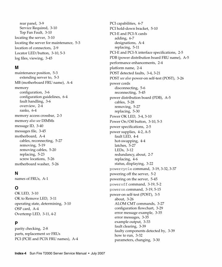
rear panel, 3-9Service Required, 3-10Top Fan Fault, 3-10
locating the server, 3-10locating the server for maintenance, 5-3location of connectors, 2-9Locator LED/button, 3-10, 5-3log files, viewing, 3-45
Mmaintenance position, 5-3
extending server to, 5-3MB (motherboard FRU name), A-4memory
configuration, 3-6configuration guidelines, 6-4fault handling, 3-6overview, 2-4ranks, 6-4
memory access crossbar, 2-3memory also see DIMMsmessage ID, 3-40messages file, 3-45motherboard, A-4
cables, reconnecting, 5-27removing, 5-19removing cables, 5-20replacing, 5-23screw locations, 5-26
motherboard washer, 5-26
Nnames of FRUs, A-1
OOK LED, 3-10OK to Remove LED, 3-11operating state, determining, 3-10OSP card, A-4Overtemp LED, 3-11, 4-2
Pparity checking, 2-8parts, replacement see FRUsPCI (PCIE and PCIX FRU names), A-4
PCI capabilities, 6-7PCI hold-down bracket, 5-10PCI-E and PCI-X cards
adding, 6-7designations, A-4replacing, 5-11
PCI-E and PCI-X interface specifications, 2-5PDB (power distribution board FRU name), A-5performance enhancements, 2-4platform name, 2-4POST detected faults, 3-4, 3-21POST see also power-on self-test (POST), 3-26power cords
disconnecting, 5-6reconnecting, 5-45
power distribution board (PDB), A-5cables, 5-28removing, 5-27replacing, 5-30
Power OK LED, 3-4, 3-10Power On/Off button, 3-10, 5-3power specifications, 2-5power supplies, 4-2, A-5
fault LED, 4-4hot-swapping, 4-4latches, 5-27LEDs, 3-12redundancy, about, 2-7replacing, 4-6status, displaying, 3-22
powercycle command, 3-19, 3-32, 3-37powering off the server, 5-2powering on the server, 5-45poweroff command, 3-19, 5-2poweron command, 3-19, 5-15power-on self-test (POST), 3-5
about, 3-26ALOM CMT commands, 3-27configuration flowchart, 3-29error message example, 3-35error messages, 3-35example output, 3-33fault clearing, 3-39faulty components detected by, 3-39how to run, 3-32parameters, changing, 3-30
Index-4 Sun Fire T2000 Server Service Manual • July 2007
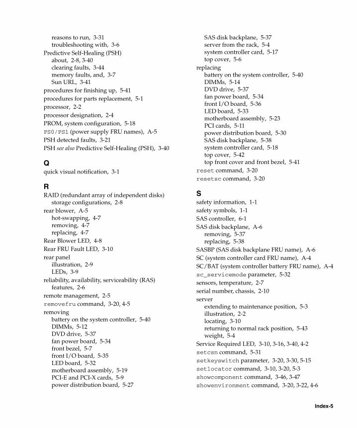
reasons to run, 3-31troubleshooting with, 3-6
Predictive Self-Healing (PSH)about, 2-8, 3-40clearing faults, 3-44memory faults, and, 3-7Sun URL, 3-41
procedures for finishing up, 5-41procedures for parts replacement, 5-1processor, 2-2processor designation, 2-4PROM, system configuration, 5-18PS0/PS1 (power supply FRU names), A-5PSH detected faults, 3-21PSH see also Predictive Self-Healing (PSH), 3-40
Qquick visual notification, 3-1
RRAID (redundant array of independent disks)
storage configurations, 2-8rear blower, A-5
hot-swapping, 4-7removing, 4-7replacing, 4-7
Rear Blower LED, 4-8Rear FRU Fault LED, 3-10rear panel
illustration, 2-9LEDs, 3-9
reliability, availability, serviceability (RAS)features, 2-6
remote management, 2-5removefru command, 3-20, 4-5removing
battery on the system controller, 5-40DIMMs, 5-12DVD drive, 5-37fan power board, 5-34front bezel, 5-7front I/O board, 5-35LED board, 5-32motherboard assembly, 5-19PCI-E and PCI-X cards, 5-9power distribution board, 5-27
SAS disk backplane, 5-37server from the rack, 5-4system controller card, 5-17top cover, 5-6
replacingbattery on the system controller, 5-40DIMMs, 5-14DVD drive, 5-37fan power board, 5-34front I/O board, 5-36LED board, 5-33motherboard assembly, 5-23PCI cards, 5-11power distribution board, 5-30SAS disk backplane, 5-38system controller card, 5-18top cover, 5-42top front cover and front bezel, 5-41
reset command, 3-20resetsc command, 3-20
Ssafety information, 1-1safety symbols, 1-1SAS controller, 6-1SAS disk backplane, A-6
removing, 5-37replacing, 5-38
SASBP (SAS disk backplane FRU name), A-6SC (system controller card FRU name), A-4SC/BAT (system controller battery FRU name), A-4sc_servicemode parameter, 5-32sensors, temperature, 2-7serial number, chassis, 2-10server
extending to maintenance position, 5-3illustration, 2-2locating, 3-10returning to normal rack position, 5-43weight, 5-4
Service Required LED, 3-10, 3-16, 3-40, 4-2setcsn command, 5-31setkeyswitch parameter, 3-20, 3-30, 5-15setlocator command, 3-10, 3-20, 5-3showcomponent command, 3-46, 3-47showenvironment command, 3-20, 3-22, 4-6
Index-5
showfaults command, 3-4, 5-15, 5-16description and examples, 3-21syntax, 3-20troubleshooting with, 3-5
showfru command, 3-20, 3-25showkeyswitch command, 3-20showlocator command, 3-20showlogs command, 3-20showplatform command, 2-10, 3-20, 5-32shutting down the system, 5-2slide rails
release lever, 5-5releasing, 5-3, 5-43
Solaris log files, 3-4Solaris OS
collecting diagnostic information from, 3-45Solaris Predictive Self-Healing (PSH) detected
faults, 3-4standby power, 5-6state of server, 3-10sun4v architecture, 2-4SunVTS, 3-2, 3-4
exercising the system with, 3-50running, 3-51tests, 3-53user interfaces, 3-50, 3-51, 3-53, 3-54
support, obtaining, 3-5switch, intrusion, 5-1syslogd daemon, 3-45system configuration PROM, 5-18system console, switching to, 3-18system controller, 3-2system controller card, A-4
battery, 5-40removing, 5-17replacing, 5-18
system temperatures, displaying, 3-22
Ttemperature sensors, 2-7TLB misses, reduction of, 2-4tools required, 5-2top cover
release button, 5-7removing, 5-6
replacing, 5-42Top Fan Fault LED, 3-10, 4-2top front cover
removing, 5-7replacing, 5-41
troubleshootingactions, 3-4DIMMs, 3-8
UUltraSPARC T1 multicore processor, 2-2, 2-3, 3-41Universal Unique Identifier (UUID), 3-40, 3-42USB connectors, 6-4USB devices, guidelines for adding, 6-3USB ports, 2-4
Vvirtual keyswitch, 3-30, 5-15voltage and current sensor status, displaying, 3-22
Wwasher for motherboard, 5-26weight of server, 5-4
Index-6 Sun Fire T2000 Server Service Manual • July 2007