Embed Size (px)
Citation preview
www.sulzer.com
Submersible Wastewater Pump Type ABS AS 0530 - 0841
6006
077
(09.
2020
)
Installation and Operating Instructionsen
1006
-00
Sulzer reserves the right to alter specifications due to technical developments !
2
Submersible Wastewater Pump Type ABS AS:
0530 0631 0830 0840 0630 0641 0831 0841
Contents1 Application areas .................................................................................................................................. 31.1 Approvals ................................................................................................................................................ 3
1.2 Explosion-proof approvals ....................................................................................................................... 3
2 Safety ..................................................................................................................................................... 32.1 Particular comments on the use of explosion-proof pumps in explosive zones. ..................................... 3
2.2 Special conditions for safe use of S-type, explosion-proof motors. ........................................................ 4
3 Technical data ....................................................................................................................................... 43.1 Nameplate ............................................................................................................................................... 4
4 Types of operation and frequency of starting .................................................................................... 55 Lifting ..................................................................................................................................................... 56 Transport ................................................................................................................................................ 67 Set-up and installation .......................................................................................................................... 67.1 Discharge line ......................................................................................................................................... 6
7.2 Installation example, concrete sump ....................................................................................................... 7
7.3 Electrical connection ............................................................................................................................... 7
7.3.1 Wiring diagrams ...................................................................................................................................... 8
7.4 Checking direction of rotation .................................................................................................................. 9
7.4.1 Changing direction of rotation ............................................................................................................... 10
8 Commissioning ................................................................................................................................... 109 Maintenance and service .................................................................................................................... 119.1 General maintenance hints ................................................................................................................... 11
9.2 Commentary on maintenance of lifting stations in accordance with EN 12056. ................................... 12
9.3 Oilfillingandchanging .......................................................................................................................... 12
9.4 Cleaning ................................................................................................................................................ 13
9.5 Venting of the volute .............................................................................................................................. 13
3
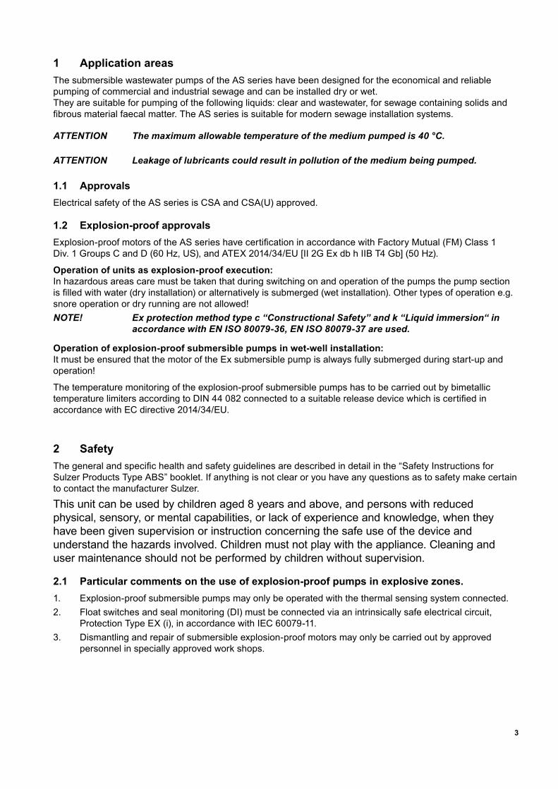
1 Application areasThe submersible wastewater pumps of the AS series have been designed for the economical and reliable pumping of commercial and industrial sewage and can be installed dry or wet. They are suitable for pumping of the following liquids: clear and wastewater, for sewage containing solids and fibrousmaterialfaecalmatter.TheASseriesissuitableformodernsewageinstallationsystems.
ATTENTION The maximum allowable temperature of the medium pumped is 40 °C.
ATTENTION Leakage of lubricants could result in pollution of the medium being pumped.
1.1 ApprovalsElectrical safety of the AS series is CSA and CSA(U) approved.
1.2 Explosion-proof approvalsExplosion-proofmotorsoftheASserieshavecertificationinaccordancewithFactoryMutual(FM)Class1 Div. 1 Groups C and D (60 Hz, US), and ATEX 2014/34/EU [II 2G Ex db h IIB T4 Gb] (50 Hz).
Operation of units as explosion-proof execution: In hazardous areas care must be taken that during switching on and operation of the pumps the pump section isfilledwithwater(dryinstallation)oralternativelyissubmerged(wetinstallation).Othertypesofoperatione.g.snore operation or dry running are not allowed!NOTE! Ex protection method type c “Constructional Safety” and k “Liquid immersion“ in
accordance with EN ISO 80079-36, EN ISO 80079-37 are used.
Operation of explosion-proof submersible pumps in wet-well installation: It must be ensured that the motor of the Ex submersible pump is always fully submerged during start-up and operation!
The temperature monitoring of the explosion-proof submersible pumps has to be carried out by bimetallic temperaturelimitersaccordingtoDIN44082connectedtoasuitablereleasedevicewhichiscertifiedinaccordance with EC directive 2014/34/EU.
2 SafetyThegeneralandspecifichealthandsafetyguidelinesaredescribedindetailinthe“SafetyInstructionsforSulzer Products Type ABS” booklet. If anything is not clear or you have any questions as to safety make certain to contact the manufacturer Sulzer.
This unit can be used by children aged 8 years and above, and persons with reduced physical, sensory, or mental capabilities, or lack of experience and knowledge, when they have been given supervision or instruction concerning the safe use of the device and understand the hazards involved. Children must not play with the appliance. Cleaning and user maintenance should not be performed by children without supervision.
2.1 Particular comments on the use of explosion-proof pumps in explosive zones.1. Explosion-proof submersible pumps may only be operated with the thermal sensing system connected.2. Floatswitchesandsealmonitoring(DI)mustbeconnectedviaanintrinsicallysafeelectricalcircuit,
Protection Type EX (i), in accordance with IEC 60079-11.3. Dismantling and repair of submersible explosion-proof motors may only be carried out by approved
personnel in specially approved work shops.
4
2.2 Special conditions for safe use of S-type, explosion-proof motors.1. The integral supply cable shall be suitably protected from mechanical damage and terminated within an
appropriate termination facility.2. Pump motors rated for use with 50/60 Hz sinusoidal supplies shall have the thermal protection devices
connected in such a way that the machine is isolated from the supply in the event of the stator reaching 130 °C.
3. Pump motors rated for use with variable frequency or non-sinusoidal supplies shall have the thermal protection devices connected in such a way that the machine is isolated from the supply in the event of thestatorreaching100°CforT4classifiedmachines,or160°CforT3classifiedmachines.
4. Thesemotorunitsarenotintendedforuserserviceorrepair,anyoperationthatmayaffecttheexplosionprotectioncharacteristicsshouldbereferredtothemanufacturer.Repairsonflameproofjointsmayonlybeperformedinaccordancewiththemanufacturer’sdesignspecifications.
3 Technical dataDetailedtechnicalinformationisavailableinthetechnicaldatasheet“SubmersibleWastewaterPumpTypeABS AS 0530 - 0841” which can be downloaded from www.sulzer.com > Products > Pumps > Submersible Pumps.
Maximumnoiselevel≤70dB.Thismaybeexceededincertaincircumstances.
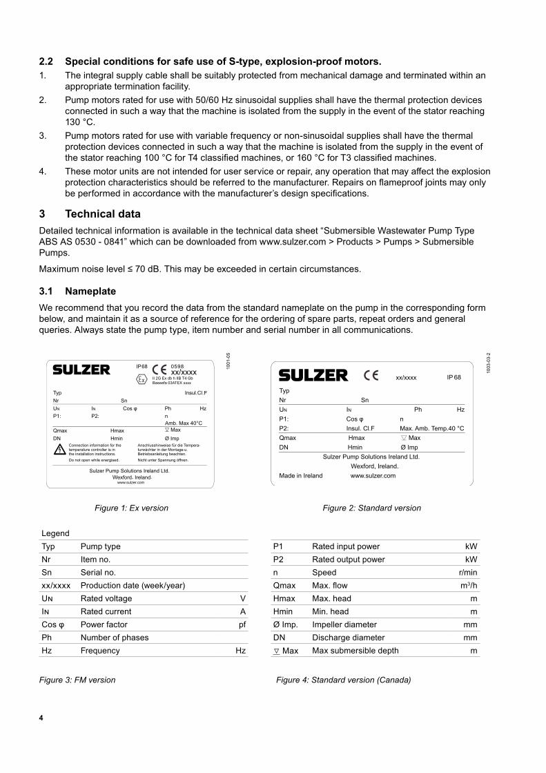
3.1 NameplateWe recommend that you record the data from the standard nameplate on the pump in the corresponding form below, and maintain it as a source of reference for the ordering of spare parts, repeat orders and general queries. Always state the pump type, item number and serial number in all communications.
Baseefa 03ATEX xxxxII 2G Ex db h IIB T4 Gb
0598
F
Amb. Max 40°CMax
1001
-05
1003
-03-
2
Figure 1: Ex version Figure 2: Standard version LegendTyp Pump type P1 Rated input power kWNr Item no. P2 Rated output power kWSn Serial no. n Speed r/minxx/xxxx Production date (week/year) Qmax Max.flow m3/hUn Rated voltage V Hmax Max.head mIn Rated current A Hmin Min.head mCosφ Power factor pf Ø Imp. Impeller diameter mmPh Number of phases DN Discharge diameter mmHz Frequency Hz ▽ Max Maxsubmersibledepth m
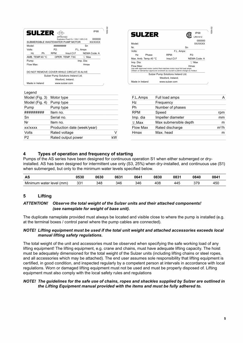
Figure 3: FM version Figure 4: Standard version (Canada)
5
1002
-02
1004
-02
LegendModel(Fig.3) Motortype F.L.Amps Fullloadamps AModel(Fig.4) Pump type Hz FrequencyPump Pump type Ph Number of phases######### Item no. RPM Speed rpmSn Serial no. Imp. dia Impeller diameter mmNr Item no. ▽ Max Maxsubmersibledepth mxx/xxxx Production date (week/year) FlowMax Rated discharge m3/hVolts Rated voltage V Hmax Max.head mP2 Rated output power kW
4 Types of operation and frequency of startingPumps of the AS series have been designed for continuous operation S1 when either submerged or dry-installed. AS has been designed for intermittent use only (S3, 25%) when dry-installed, and continuous use (S1) whensubmerged,butonlytotheminimumwaterlevelsspecifiedbelow.
AS 0530 0630 0631 0641 0830 0831 0840 0841Minimumwaterlevel(mm) 331 348 346 346 408 445 379 450
5 LiftingATTENTION! Observe the total weight of the Sulzer units and their attached components! (see nameplate for weight of base unit).
The duplicate nameplate provided must always be located and visible close to where the pump is installed (e.g. at the terminal boxes / control panel where the pump cables are connected).
NOTE! Lifting equipment must be used if the total unit weight and attached accessories exceeds local manual lifting safety regulations.
The total weight of the unit and accessories must be observed when specifying the safe working load of any lifting equipment! The lifting equipment, e.g. crane and chains, must have adequate lifting capacity. The hoist must be adequately dimensioned for the total weight of the Sulzer units (including lifting chains or steel ropes, and all accessories which may be attached). The end user assumes sole responsibility that lifting equipment is certified,ingoodcondition,andinspectedregularlybyacompetentpersonatintervalsinaccordancewithlocalregulations. Worn or damaged lifting equipment must not be used and must be properly disposed of. Lifting equipment must also comply with the local safety rules and regulations
NOTE! The guidelines for the safe use of chains, ropes and shackles supplied by Sulzer are outlined in the Lifting Equipment manual provided with the items and must be fully adhered to.
6
6 Transport
During transport the unit should not be dropped or thrown.
The unit should never be raised or lowered by the power cable.
Theunitisfittedwithaliftingdevicetowhichachainandshacklemaybeattachedfortransportpurposes.
Any hoist used must be adequately dimensioned for the weight of the unit.
All relevant safety regulators as well as general good technical practice must be complied with.
7 Set-up and installationATTENTION All relevant regulations covering sewage pumping installations, and where
applicable, explosion-proof installations, must be complied with.
The cableducttothecontrolpanelshouldbemadegas-tightbyfillingwithfoamafterthepowersupply and control circuit cables have been laid.
Particular attention must be paid to the safety regulations covering work in closed areas in sewage plants as well as good general technical practices .
7.1 Discharge lineThe discharge line must be installed in compliance with the relevant regulations. DIN 1986/100 and EN 12056 applies in particular to the following:
- Thedischargelineshouldbefittedwithabackwashloop(180°bend)locatedabovethebackwashlevelandshouldthenflowbygravityintothecollectionlineorsewer.
- The discharge line should not be connected to a down pipe.
- Nootherinflowsordischargelinesshouldbeconnectedtothisdischargeline.
ATTENTION Thedischargelineshouldbeinstalledsothatitisnotaffectedbyfrost.
7
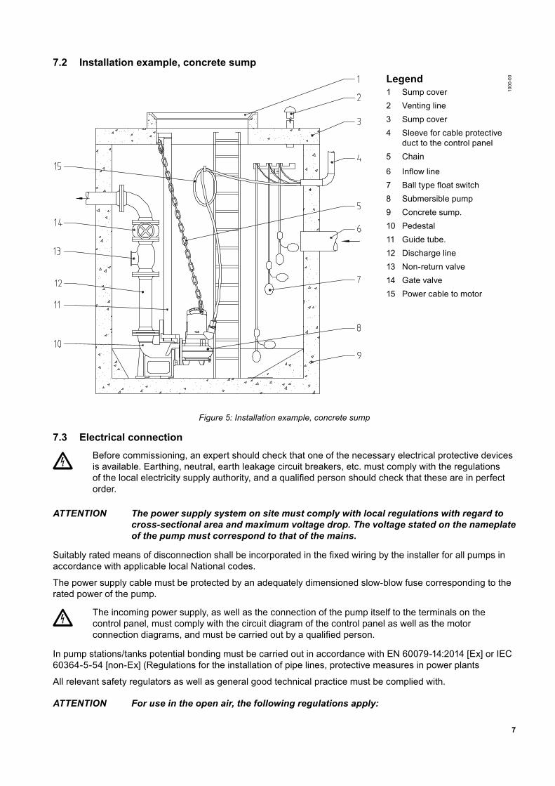
7.2 Installation example, concrete sumpLegend
1000
-00
1 Sump cover 2 Venting line 3 Sump cover 4 Sleeve for cable protective
duct to the control panel5 Chain
6 Inflowline7 Balltypefloatswitch8 Submersible pump 9 Concrete sump. 10 Pedestal 11 Guide tube. 12 Discharge line 13 Non-return valve 14 Gate valve 15 Power cable to motor
Figure 5: Installation example, concrete sump
7.3 Electrical connectionBefore commissioning, an expert should check that one of the necessary electrical protective devices is available. Earthing, neutral, earth leakage circuit breakers, etc. must comply with the regulations ofthelocalelectricitysupplyauthority,andaqualifiedpersonshouldcheckthattheseareinperfectorder.
ATTENTION The power supply system on site must comply with local regulations with regard to cross-sectional area and maximum voltage drop. The voltage stated on the nameplate of the pump must correspond to that of the mains.
Suitablyratedmeansofdisconnectionshallbeincorporatedinthefixedwiringbytheinstallerforallpumpsinaccordance with applicable local National codes.
The power supply cable must be protected by an adequately dimensioned slow-blow fuse corresponding to the rated power of the pump.
The incoming power supply, as well as the connection of the pump itself to the terminals on the control panel, must comply with the circuit diagram of the control panel as well as the motor connectiondiagrams,andmustbecarriedoutbyaqualifiedperson.
In pump stations/tanks potential bonding must be carried out in accordance with EN 60079-14:2014 [Ex] or IEC 60364-5-54 [non-Ex] (Regulations for the installation of pipe lines, protective measures in power plants
All relevant safety regulators as well as general good technical practice must be complied with.
ATTENTION For use in the open air, the following regulations apply:
8
Submersiblepumpsusedoutdoorsmustbefittedwithapowercableofatleast10mlength.Otherregulationsmayapplyindifferentcountries. In all installations, the power supply to the pump must be via a residual current device (e.g. RCD, ELCB, RCBO etc.)witharatedresidualoperatingcurrentnotexceeding30mA.Forinstallationsnothavingafixedresidualcurrent device the pump must be supplied to the power supply through a portable version of the device.
Allthreephasepumpsmustbeinstalledwithmotorstartingandoverloadprotectivedevicesinthefixedwiringby the installer. Such motor control and protective devices must comply with the requirements of IEC standard 60947-4-1.Theymustberatedforthemotorthattheycontrol,andwiredandset/adjustedaccordingtotheinstructions provided by the manufacturer.
Risk of electrical shock. Do not remove cord and strain relief and do not connect conduit to pump.
Thefollowingcomponentsshouldbeincorporatedinthefixedwiringforallsinglephasepumps:
• Motorstartingand/orrunningcapacitorthatcomplieswiththerequirementsofIEC60252-1andratedasspecifiedintheinstallationinstruction.ThecapacitorshallbeclassS2orS3.
• MotorcontactorthatcomplieswiththerequirementsofIECStandard60947-4-1andratedforthemotorthatit controls.
This pump has not been investigated for use in swimming pools.
NOTE Please consult your electrician.
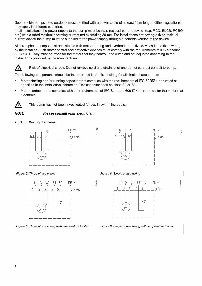
7.3.1 Wiring diagrams
1013
-01
1016
-00
Figure 5: Three phase wiring Figure 8: Single phase wiring
1014
-00
1017
-00
Figure 6: Three phase wiring with temperature limiter Figure 9: Single phase wiring with temperature limiter
9
1015
-00
1018
-00
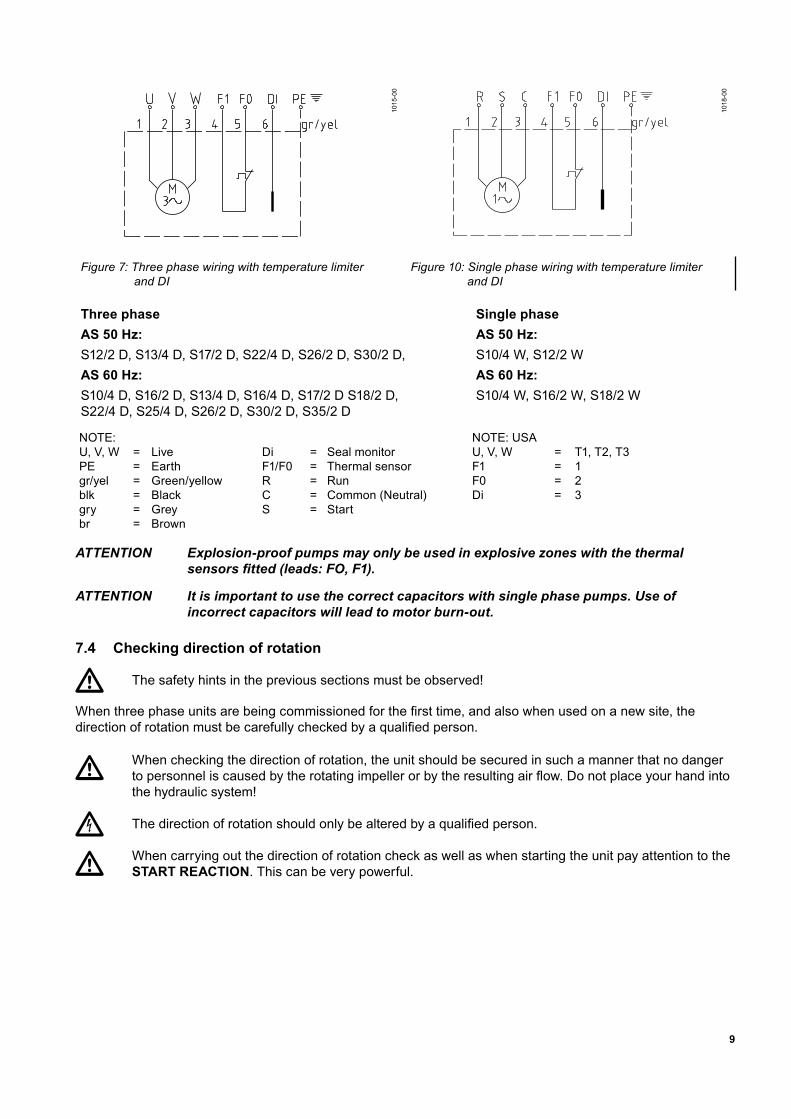
Figure 7: Three phase wiring with temperature limiter and DI
Figure 10: Single phase wiring with temperature limiter and DI
Three phase Single phaseAS 50 Hz: AS 50 Hz:S12/2 D, S13/4 D, S17/2 D, S22/4 D, S26/2 D, S30/2 D, S10/4 W, S12/2 WAS 60 Hz: AS 60 Hz:S10/4 D, S16/2 D, S13/4 D, S16/4 D, S17/2 D S18/2 D, S22/4 D, S25/4 D, S26/2 D, S30/2 D, S35/2 D
S10/4 W, S16/2 W, S18/2 W
NOTE: NOTE: USAU, V, W = Live Di = Seal monitor U, V, W = T1, T2, T3PE = Earth F1/F0 = Thermal sensor F1 = 1gr/yel = Green/yellow R = Run F0 = 2blk = Black C = Common (Neutral) Di = 3gry = Grey S = Startbr = Brown
ATTENTION Explosion-proof pumps may only be used in explosive zones with the thermal sensorsfitted(leads:FO,F1).
ATTENTION It is important to use the correct capacitors with single phase pumps. Use of incorrect capacitors will lead to motor burn-out.
7.4 Checking direction of rotation
The safety hints in the previous sections must be observed!
Whenthreephaseunitsarebeingcommissionedforthefirsttime,andalsowhenusedonanewsite,thedirectionofrotationmustbecarefullycheckedbyaqualifiedperson.
When checking the direction of rotation, the unit should be secured in such a manner that no danger topersonneliscausedbytherotatingimpellerorbytheresultingairflow.Donotplaceyourhandintothe hydraulic system!
The directionofrotationshouldonlybealteredbyaqualifiedperson.
When carrying out the direction of rotation check as well as when starting the unit pay attention to the START REACTION. This can be very powerful.
10
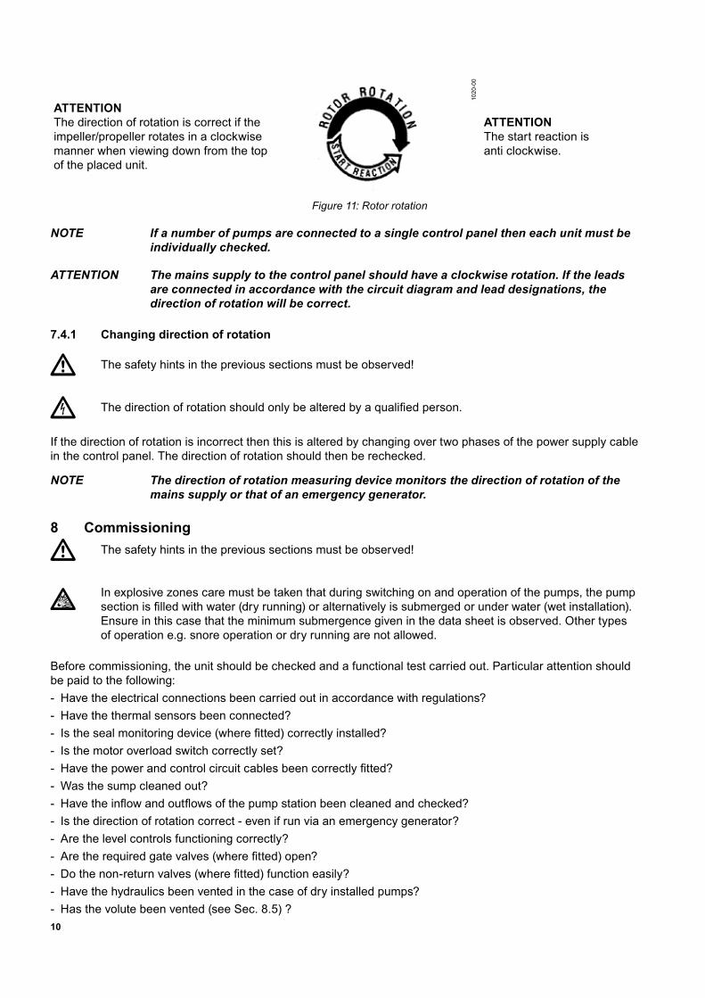
ATTENTION The direction of rotation is correct if the impeller/propeller rotates in a clockwise manner when viewing down from the top of the placed unit.
1020
-00
ATTENTION The start reaction is anti clockwise.
Figure 11: Rotor rotation
NOTE If a number of pumps are connected to a single control panel then each unit must be individually checked.
ATTENTION The mains supply to the control panel should have a clockwise rotation. If the leads are connected in accordance with the circuit diagram and lead designations, the direction of rotation will be correct.
7.4.1 Changing direction of rotation
The safety hints in the previous sections must be observed!
Thedirectionofrotationshouldonlybealteredbyaqualifiedperson.
If the direction of rotation is incorrect then this is altered by changing over two phases of the power supply cable in the control panel. The direction of rotation should then be rechecked.
NOTE The direction of rotation measuring device monitors the direction of rotation of the mains supply or that of an emergency generator.
8 CommissioningThe safety hints in the previous sections must be observed!
In explosive zones care must be taken that during switching on and operation of the pumps, the pump sectionisfilledwithwater(dryrunning)oralternativelyissubmergedorunderwater(wetinstallation).Ensure in this case that the minimum submergence given in the data sheet is observed. Other types of operation e.g. snore operation or dry running are not allowed.
Before commissioning, the unit should be checked and a functional test carried out. Particular attention should be paid to the following: - Have the electrical connections been carried out in accordance with regulations? - Have the thermal sensors been connected? - Isthesealmonitoringdevice(wherefitted)correctlyinstalled? - Is the motor overload switch correctly set? - Havethepowerandcontrolcircuitcablesbeencorrectlyfitted? - Was the sump cleaned out? - Havetheinflowandoutflowsofthepumpstationbeencleanedandchecked? - Is the direction of rotation correct - even if run via an emergency generator? - Are the level controls functioning correctly? - Aretherequiredgatevalves(wherefitted)open? - Dothenon-returnvalves(wherefitted)functioneasily? - Have the hydraulics been vented in the case of dry installed pumps? - Has the volute been vented (see Sec. 8.5) ?
11
9 Maintenance and service
To avoid danger if the power cable is damaged, it must be replaced by the manufacturer or its service agentorasimilarlyqualifiedperson.
Before commencing any maintenance work the unit should be completely disconnected from the mainsbyaqualifiedpersonandcareshouldbetakenthatitcannotbeinadvertentlyswitchedbackon.
Servicingmustonlybecarriedoutbyqualifiedpersonnel.
When carrying out any repair or maintenance work, the safety regulations covering work in enclosed areas of sewage installations as well as good general technical pratices should be followed.
NOTE The maintenance hints given here are not designed for “do-it-yourself” repairs as special technical knowledge is required.
NOTE A maintenance contract with our service department will guarantee you the best technical service under all circumstances.
9.1 General maintenance hintsSulzersubmersiblepumpsarereliablequalityproductseachbeingsubjectedtocarefulfinalinspection.Lubricated-for-life ball bearings together with monitoring devices ensure optimum pump reliability provided that the pump has been connected and operated in accordance with the operating instructions. Should, nevertheless, a malfunction occur, do not improvise but ask your Sulzer Customer Service Department for assistance. Thisappliesparticularlyifthepumpiscontinuallyswitchedoffbythecurrentoverloadinthecontrolpanel,bythe thermal sensors of the thermo-control system, or by the seal monitoring system (DI). Regular inspection and care is recommended to ensure a long service life.
NOTE The Sulzer Service Organisation would be pleased to advise you on any applications you may have and to assist you in solving your pumping problems.
NOTE The Sulzer warranty conditions are only valid provided that any repair work has been carried out in Sulzer approved workshop and where original Sulzer spare parts have been used.
NOTE When carrying out repairs, only original spare parts supplied by the manufacturer should be used.
WARNING: ATEX- and FM-rated AS pumps are approved for use in hazardous locations. If an Ex-rated pump is serviced or repaired in a workshop that is not Ex-approved then it must no longer be used in hazardous locations. In that case the Ex nameplate must be removed and replaced by the standard nameplate, or where instead a standard and a secondary Ex nameplate is fitted to the pump the secondary nameplate must be removed.
12
9.2 Commentary on maintenance of lifting stations in accordance with EN 12056.It is recommended that the lifting station be inspected monthly and its function checked.
InaccordancewithENregulations,theliftingstationshouldbemaintainedbyaqualifiedpersonatthefollowing intervals:
• in commercial premises every three months.
• in apartment blocks every six months.
• in a single family home once a year.
Inadditionwerecommendthatamaintenancecontractbetakenoutwithaqualifiedcompany.
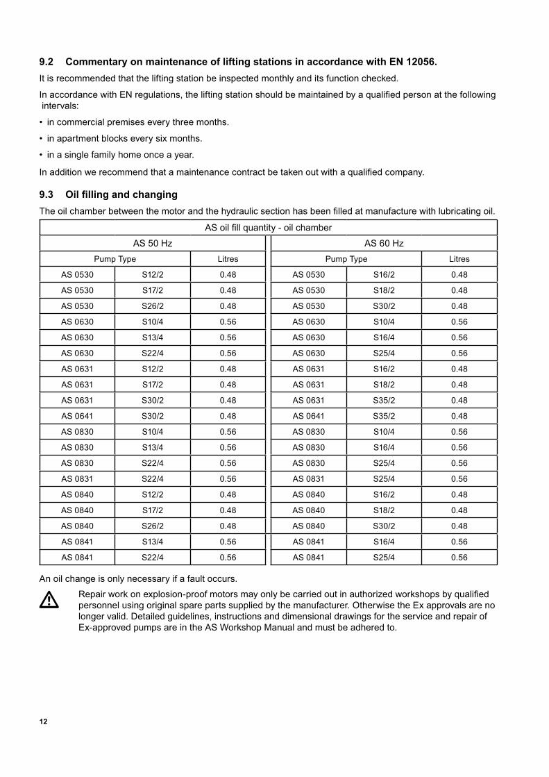
9.3 Oil filling and changingTheoilchamberbetweenthemotorandthehydraulicsectionhasbeenfilledatmanufacturewithlubricatingoil.
ASoilfillquantity-oilchamberAS 50 Hz AS 60 Hz
Pump Type Litres Pump Type Litres
AS 0530 S12/2 0.48 AS 0530 S16/2 0.48
AS 0530 S17/2 0.48 AS 0530 S18/2 0.48
AS 0530 S26/2 0.48 AS 0530 S30/2 0.48
AS 0630 S10/4 0.56 AS 0630 S10/4 0.56
AS 0630 S13/4 0.56 AS 0630 S16/4 0.56
AS 0630 S22/4 0.56 AS 0630 S25/4 0.56
AS 0631 S12/2 0.48 AS 0631 S16/2 0.48
AS 0631 S17/2 0.48 AS 0631 S18/2 0.48
AS 0631 S30/2 0.48 AS 0631 S35/2 0.48
AS 0641 S30/2 0.48 AS 0641 S35/2 0.48
AS 0830 S10/4 0.56 AS 0830 S10/4 0.56
AS 0830 S13/4 0.56 AS 0830 S16/4 0.56
AS 0830 S22/4 0.56 AS 0830 S25/4 0.56
AS 0831 S22/4 0.56 AS 0831 S25/4 0.56
AS 0840 S12/2 0.48 AS 0840 S16/2 0.48
AS 0840 S17/2 0.48 AS 0840 S18/2 0.48
AS 0840 S26/2 0.48 AS 0840 S30/2 0.48
AS 0841 S13/4 0.56 AS 0841 S16/4 0.56
AS 0841 S22/4 0.56 AS 0841 S25/4 0.56
An oil change is only necessary if a fault occurs.Repair workonexplosion-proofmotorsmayonlybecarriedoutinauthorizedworkshopsbyqualifiedpersonnel using original spare parts supplied by the manufacturer. Otherwise the Ex approvals are no longer valid. Detailed guidelines, instructions and dimensional drawings for the service and repair of Ex-approvedpumpsareintheASWorkshopManualandmustbeadheredto.
13
9.4 CleaningIf the pump is used for transportable applications then it should be cleaned after each usage by pumping clear waterinordertoavoiddepositsofdirtandencrustation.Inthecaseoffixedinstallation,werecommendthatthe functioning of the automatic level control system be checked regularly. By switching the selection switch (switchsetting“HAND”)thesumpwillbeemptied.Ifdepositsofdirtarevisibleonthefloatsthentheseshouldbe cleaned. After cleaning, the pump should be rinsed out with clear water and a number of automatic pumping cycles carried out.
9.5 Venting of the voluteAfter lowering the pump into a sump full of water, an air lock may occur in the volute and cause pumping problems. In that case, shake or raise and lower the pump repeatedly until resulting air bubbles cease to appear at surface level. If necessary, repeat this venting procedure.

14

15

Sulzer Pump Solutions Ireland Ltd. Clonard Road, Wexford, Ireland Tel. +353 53 91 63 200. www.sulzer.com