Embed Size (px)
Citation preview
STUDY PACKAGE 1e
GATEINSTRUMENTATION ENGINEERING
Vol 3 of 5
BASICS OF MEASUREMENT SYSTEMS
TRANSDUCERS, MEChANICAl MEASUREMENT AND INDUSTRIAl INSTRUMENTATION
ElECTRICAl AND ElECTRONIC MEASUREMENTS
ANAlYTICAl, OPTICAl AND BIOMEDICAl INSTRUMENTATION
R. K. Kanodia Ashish Murolia
NODIA & COMPANY

GATE Instrumentation Engineering Vol 3 of 5RK Kanodia and Ashish Murolia
Copyright © By NODIA & COMPANY
Information contained in this book has been obtained by author, from sources believes to be reliable. However, neither NODIA & COMPANY nor its author guarantee the accuracy or completeness of any information herein, and NODIA & COMPANY nor its author shall be responsible for any error, omissions, or damages arising out of use of this information. This book is published with the understanding that NODIA & COMPANY and its author are supplying information but are not attempting to render engineering or other professional services.
MRP 570.00
NODIA & COMPANYB - 8, Dhanshree Ist, Central Spine, Vidyadhar Nagar, Jaipur - 302039Ph : +91 - 141 - 2101150, www.nodia.co.inemail : [email protected]
Printed by Nodia and Company, Jaipur

To Our Parents


PREFACE
The objective of this study package is to develop in the GATE aspirants the ability to solve GATE level problems of Instrumentation Engineering Paper. The highly increased competition in GATE exam from last few years necessitate an in-depth knowledge of the concepts for the GATE aspirants. There are lots of study packages available for GATE Instrumentation Engineering, which includes the theory and problem sets. But through this package our notion is to develop the problem solving approach rather than just introducing the theory and problem set. This study package fulfills all the requirements of a GATE aspirant to prepare for the exam.
There is no special pre-requisite before starting this study package. Although it is always recommended to refer other standard text books to clear doubts in a typical problem. The study package is published in 5 different volumes that cover the different subjects of GATE Instrumentation Engineering Paper. As the weightage of General Aptitude and Engineering Mathematics in the Instrumentation Engineering paper are 15 % each, and the subjects are very much wide in the syllabus; these subjects are published in separate volumes to provide practice problem set on all the important topics of the subjects. Rest three volumes cover the core subjects of GATE Instrumentation Engineering.
In the very first volume of this study package, General Aptitude is introduced. General aptitude is divided into two sections: verbal ability and numerical ability. Some important rules of grammar is introduced at the starting of verbal ability section, and then different types of verbal ability problems are given in separate chapters. At the end of each chapter answers of the problems are described with detailed theory and grammatical rule. The numerical ability part does not include theory as it is expected from an engineering students that they are very well known to the basic mathematical formulas of under 10th class. In numerical ability section, the chapters are organized such as to cover all types of problems asked in previous GATE papers. There is the detailed solutions available for each of the numerical ability problems such that even an average student can clear his/her doubts easily.
In volume 2 of the study package, Engineering Mathematics is introduced. Each chapter of Engineering Mathematics introduces a brief theory with problem solving methodology and important formulas at the starting and then the problems are given in a graded manner from basic to advance level. At last, the solutions are given with a detailed description of formulas and concepts used to solve it.
Volumes 3, 4 and 5 include the core subjects of instrumentation. The subjects with interrelated topics are taken in the same volume. Volume 3 includes the subjects:

Basics of Measurement Systems; Electrical & Electronic Measurement; Transducers, Mechanical Measurement and Industrial Instrumentation; Analytical, Optical & Biomedical Instrumentation. Volume 4 includes the subjects: Basics of Circuits, Analog Electronics, Digital Electronics. Volume 5 includes the subjects: Signals & Systems; Communication Systems; Control Systems and Process Control. For each of the subjects, the chapters are organized in a manner to cover the complete syllabus with a balanced number of problems on each topic. In starting of each chapter, a brief theory is given that includes formula, problem solving methodology and some important points to remember. There are enough number of problems to cover all the varieties, and the problems are graded from basic to advance level such that a GATE aspirant can easily understand concepts while solving problems. Each and every problems are solved with a good description to avoid any confusion or doubt.
There are two types of problems being asked in GATE exam: MCQ (Multiple Choice Questions) and NAT (Numerical Answer Type questions). Both type of problems are given in this study package. Solutions are presented in a descriptive and step-by-step manner. The diagrams in the book are clearly illustrated. Overall, a very simple language is used throughout this study package to facilitate easy understanding of the concepts.
We believe that each volume of GATE Study Package helps a student to learn fundamental concepts and develop problem solving skills for a subject, which are key essentials to crack GATE. Although we have put a vigorous effort in preparing this book, some errors may have crept in. We shall appreciate and greatly acknowledge all constructive comments, criticisms, and suggestions from the users of this book at [email protected]
We wish you good luck !
Authors
Acknowledgements
We would like to express our sincere thanks to all the co-authors, editors, and reviewers for their efforts in making this project successful. We would also like to thank Team NODIA for providing professional support for this project through all phases of its development. At last, we express our gratitude to God and our Family for providing moral support and motivation.
Authors

SYllABUS
General Aptitude (GA):Verbal Ability : English grammar, sentence completion, verbal analogies, word groups, instructions, critical reasoning and verbal deduction.
Numerical Ability : Numerical computation, numerical estimation, numerical reasoning and data interpretation.
Section 1 : Engineering MathematicsLinear Algebra: Matrix algebra, systems of linear equations, Eigen values and Eigen vectors.
Calculus: Mean value theorems, theorems of integral calculus, partial derivatives, maxima and minima, multiple integrals, Fourier series, vector identities, line, surface and volume integrals, Stokes, Gauss and Green’s theorems.
Differential equations: First order equation (linear and nonlinear), higher order linear differential equations with constant coefficients, method of variation of parameters, Cauchy’s and Euler’s equations, initial and boundary value problems, solution of partial differential equations: variable separable method.
Analysis of complex variables: Analytic functions, Cauchy’s integral theorem and integral formula, Taylor’s and Laurent’s series, residue theorem, solution of integrals.
Probability and Statistics: Sampling theorems, conditional probability, mean, median, mode and standard deviation, random variables, discrete and continuous distributions: normal, Poisson and binomial distributions.
Numerical Methods: Matrix inversion, solutions of non-linear algebraic equations, iterative methods forsolving differential equations, numerical integration, regression and correlation analysis.Instrumentation Engineering
Section 2: Electrical Circuits: Voltage and current sources: independent, dependent, ideal and practical; v - i relationships of resistor, inductor, mutual inductor and capacitor; transient analysis of RLC circuits with dc excitation.
Kirchoff’s laws, mesh and nodal analysis, superposition, Thevenin, Norton, maximum power transfer and reciprocity theorems.
Peak-, average- and rms values of ac quantities; apparent- active- nd reactive powers; phasor analysis, impedance and admittance; series and parallel resonance, locus diagrams, realization of basic filters with R, L and C elements.
One-port and two-port networks, driving point impedance and admittance, open-, and short circuit parameters.
Section 3: Signals and Systems Periodic, aperiodic and impulse signals; Laplace, Fourier and z-transforms; transfer function, frequency response of first and second order linear time invariant systems, impulse response of systems; convolution, correlation. Discrete time system: impulse response, frequency response, pulse transfer function; DFT and FFT; basics of IIR and FIR filters.
Section 4: Control SystemsFeedback principles, signal flowgraphs, transient response, steady-state-errors, Bode plot, phase and
gain margins, Routh and Nyquist criteria, root loci, design of lead, lag and lead-lag compensators, state-space representation of systems; time-delay systems; mechanical, hydraulic and pneumatic system components, synchro pair, servo and stepper motors, servo valves; on-off, P, P-I, P-I-D, cascade, feedforward, and ratio controllers.
Section 5: Analog Electronics Characteristics and applications of diode, Zener diode, BJT and MOSFET; small signal analysis of transistor circuits, feedback amplifiers. Characteristics of operational amplifiers; applications of opamps: difference amplifier, adder, subtractor, integrator, differentiator, instrumentation amplifier, precision rectifier, active filters and other circuits. Oscillators, signal generators, voltage controlled oscillators and phase locked loop.
Section 6: Digital Electronics Combinational logic circuits, minimization of Boolean functions. IC families: TTL and CMOS. Arithmetic circuits, comparators, Schmitt trigger, multi-vibrators, sequential circuits, flip-flops, shift registers, timers and counters; sample-and-hold circuit, multiplexer, analog-to-digital (successive approximation, integrating, flash and sigma- delta) and digital-to-analog converters (weighted R, R-2R ladder and current steering logic). Characteristics of ADC and DAC (resolution, quantization, significant bits, conversion/settling time); basics of number systems, 8-bit microprocessor and microcontroller: applications, memory and input-output interfacing; basics of data acquisition systems.
Section 7: Measurements SI units, systematic and random errors in measurement, expression of uncertainty -accuracy and precision index, propagation of errors. PMMC, MI and dynamometer type instruments; dc potentiometer; bridges for measurement of R, L and C, Q-meter. Measurement of voltage, current and power in single and three phase circuits; ac and dc current probes; true rms meters, voltage and current scaling, instrument transformers, timer/counter, time, phase and frequency measurements, digital voltmeter, digital multimeter; oscilloscope, shielding and grounding.
Section 8: Sensors and Industrial Instrumentation Resistive-, capacitive-, inductive-, piezoelectric-, Hall effect sensors and associated signal conditioning circuits; transducers for industrial instrumentation: displacement (linear and angular), velocity, acceleration, force, torque, vibration, shock, pressure (including low pressure), flow (differential pressure, variable area, electromagnetic, ultrasonic, turbine and open channel flow meters) temperature (thermocouple, bolometer, RTD (3/4 wire), thermistor, pyrometer and semiconductor); liquid level, pH, conductivity and viscosity measurement.
Section 9: Communication and Optical Instrumentation Amplitude-and frequency modulation and demodulation; Shannon’s sampling theorem, pulse code modulation; frequency and time division multiplexing, amplitude- , phase-, frequency-, pulse shift keying for digital modulation; optical sources and detectors: LED, laser, photo-diode, light dependent resistor and their characteristics; interferometer: applications in metrology; basics of fiber optic sensing.
CONTENTS
BASICS OF MEASUREMENT SYSTEMS
1 ChARACTERISTICS Of MEASUREMENT SySTEMS
1.1 IntroductIon 3
1.2 MeasureMent Methods 3
1.2.1 Direct Measurement Methods 4
1.2.2 Indirect Measurement Methods 4
1.3 MeasureMent systeM 4
1.4 statIc characterIstIcs of MeasureMent systeM 6
1.4.1 Accuracy 6
1.4.2 Precision 6
1.4.3 Repeatability 7
1.4.4 Reproducibility 7
1.4.5 Tolerance 7
1.4.6 Linearity 8
1.4.7 Resolution 8
1.4.8 Sensitivity 8
1.4.9 Dead Zone 9
1.4.10 Hysteresis Effect 9
1.4.11 Threshold 9
1.4.12 Range 10
1.5 dynaMIc characterIstIcs of MeasureMent systeMs 10
1.5.1 Zero order instrument 10
1.5.2 First order instrument 10
1.5.3 Second order instrument 10
2 ERROR ANd UNCERTAINTy ANAlySIS
2.1 IntroductIon 27
2.2 errors In MeasureMent 27
2.2.1 Absolute Error 27
2.2.2 Relative Error 27
2.2.3 Percentage Error 27
2.3 LIMItIng error 28
2.3.1 Relative Limiting Error 28
2.3.2 Percentage Limiting Error 28
2.4 types of errors 29
2.4.1 Gross Errors 29
2.4.2 Systematic Errors 29
2.5 randoM errors 30
2.5.1 Statistical Analysis of Measurements Subject to Random Errors 30
2.5.2 Gaussian Error Analysis 31
2.6 coMbInatIon of errors 33
2.6.1 Sum of Two Quantities 33
2.6.2 Difference of Two Quantities 33
2.6.3 Product of two Components 33
2.6.4 Quotient 34
2.6.5 Power of a Factor 34
2.6.6 Composite Factors 34
3 STATISTICAl ANAlySIS Of dATA
3.1 IntroductIon 55
3.2 probabILIty 55
3.2.1 Joint Probability 55
3.2.2 Conditional Probability 56
3.2.3 Statistical Independence 56
3.3 randoM VarIabLe 56
3.3.1 Discrete Random Variable 56
3.3.2 Continuous Random Variable 57
3.4 transforMatIon of randoM VarIabLes 57
3.5 MuLtIpLe randoM VarIabLes 58
3.6 statIstIcaL aVerage of randoM VarIabLe 59
3.6.1 Mean or Expected Value 59
3.6.2 Moments 59
3.6.3 Variance 60
3.6.4 Standard Deviation 60
3.6.5 Characteristic Function 60
3.6.6 Joint Moments 60
3.6.7 Covariance 61
3.6.8 Correlation Coefficient 61
3.7 soMe IMportant probabILIty dIstrIbutIons 61
3.7.1 Binomial Distribution 61
3.7.2 Poisson Distribution 62
3.7.3 Gaussian Distribution 62
3.7.4 Rayleigh Distribution 64
4 CURvE fITTING
4.1 IntroductIon 91
4.2 Methods of curVe fIttIng 91
4.3 fIttIng of a straIght LIne 92
4.4 fIttIng of a paraboLa 92
ElECTRICAl & ElECTRONIC MEASUREMENTS
1 ElECTROMEChANICAl INdICATING INSTRUMENT
1.1 IntroductIon 3
1.2 pMMc InstruMent 3
1.2.1 Construction and Working 3
1.3 dc aMMeters 5
1.3.1 Shunt Resistor 5
1.3.2 Ayrton Shunt 6
1.4 dc VoLtMeter 6
1.4.1 Multiplier Resistor 6
1.4.2 Multirange Voltmeter 7
1.5 ohMMeter 7
1.5.1 Series-Type Ohmmeter 7
1.5.2 Shunt-Type Ohmmeter 8
1.6 MuLtIMeter 8
2 MEASUREMENT Of RESISTANCE
2.1 IntroductIon 29
2.2 aMMeter-VoLtMeter Method 29
2.3 ohMMeter Method 30
2.4 Wheatstone brIdge Method 31
3 MEASUREMENT Of INdUCTANCE, CApACITANCE
3.1 IntroductIon 45
3.2 MeasureMent of Inductance 45
3.2.1 Inductance Comparison Bridge 45
3.2.2 Maxwell Bridge 46
3.2.3 Hay Inductance Bridge 47
3.3 MeasureMent of capacItance 48
3.3.1 De-sauty’s Bridge 49
3.3.2 Schering Bridge 49
3.4 Vector IMpedance Meter 50
3.5 Q-Meter 51
4 ElECTRONIC INSTRUMENTS fOR MEASURING BASIC pARAMETERS
4.1 IntroductIon 71
4.2 eLectronIc VoLtMeter 71
4.3 anaLog eLectronIc VoLtMeter 72
4.3.1 AC Electronic Voltmeter 72
4.3.2 DC Electronic Voltmeter 75
4.4 dIgItaL eLectronIc VoLtMeter 77
4.4.1 Resolution and Sensitivity of DVM 77
4.4.2 Types of Digital Voltmeters 78
4.5 eLectronIc MuLtIMeter 80
4.5.1 Analog Electronic Multimeter 80
4.5.2 Digital Electronic Multimeter 81
4.6 MeasureMent of freQuency 81
4.6.1 Bridge Method 82
4.6.2 Frequency Meter 83
4.7 rf poWer MeasureMent 84
4.7.1 RF Power Measurement Using Dummy Load 84
4.7.2 Bolometer Bridge Method for RF Power Measurement 85
4.7.3 Calorimetric Method for RF Power Measurement 86
4.8 shIeLdIng and groundIng 86
4.8.1 Grounding 86
4.8.2 Shielding 89
5 CAThOdE RAy OSCIllOSCOpES
5.1 IntroductIon 105
5.2 basIc cro cIrcuIt 105
5.2.1 CRT Construction 105
5.2.2 Deflection System 106
5.2.3 Focussing System 107
5.2.4 Astigmatism 109
5.2.5 Time Base Generator 109
5.2.6 Synchronising Circuit 110
5.2.7 Blanking Circuit 111
5.2.8 Delay Line 111
5.3 cro probes 112
5.4 oscILLoscope technIQues of MeasureMents 113
5.4.1 Measurement of Voltage 114
5.4.2 Measurement of Current 114
5.4.3 Measurement of Frequency 114
5.4.4 Measurement of Phase Angle 118
6 WAvEfORM ANAlySERS
6.1 IntroductIon 141
6.2 sIgnaL anaLysIs technIQues 141
6.3 WaVe anaLyzer 142
6.3.1 Frequency-Selective wave Analyzer 142
6.3.2 Heterodyne Wave Analyzer 143
6.4 harMonIc dIstortIon anaLyzer 144
6.4.1 Tuned Circuit Harmonic Analyzer 145
6.4.2 Heterodyne Harmonic Analyzer 145
6.4.3 Fundamental Suppression Harmonic Distortion Analyzer 146
6.5 spectruM anaLyzer 148
6.5.1 Filter Bank Spectrum Analyzer 148
6.5.2 Swept Superheterodyne Spectrum Analyzer 149
6.5.3 Spectra of Different Signals 150
TRANSDUCERS, MEChANICAl MEASUREMENT
& INDUSTRIAl INSTRUMENTATION
1 ElECTRICAl TRANSdUCERS
1.1 IntroductIon 3
1.2 cLassIfIcatIon of eLectrIcaL transducers 3
1.2.1 Passive Transducers 3
1.2.2 Active Transducers 5
1.3 resIstIVe transducer 5
1.3.1 Resistance Thermometers 7
1.3.2 Resistive Displacement Transducers 7
1.3.3 Strain Gauge 7
1.4 InductIVe transducers 10
1.4.1 Operating Principle of Inductive Transducers 10
1.4.2 Differential Transducers 11
1.5 capacItIVe transducer 11
1.5.1 Operating Principle of Capacitive Transducers 11
1.5.2 Capacitive Thickness Transducer 13
1.5.3 Capacitive Displacement Transducers 14
1.6 pIezoeLectrIc transducer 14
1.6.1 Measurement of Force Using Piezoelectric Transducer 14
1.6.2 Equivalent Circuit of a Piezoelectric Transducer 15
1.6.3 Loading Effect on Piezoelectric Transducer 16
2 SIGNAl CONdITIONING fOR ElECTRICAl TRANSdUCER
2.1 IntroductIon 53
2.2 sIgnaL condItIonIng systeM 53
2.3 Input cIrcuIts 54
2.3.1 Power supplies 55
2.3.2 Constant Voltage Potentiometer Circuit 55
2.3.3 Constant Current Potentiometer Circuit 56
2.3.4 Constant Voltage Wheatstone Bridge Circuit 57
2.3.5 Constant Current Wheatstone Bridge Circuit 57
2.4 aMpLIfIers 58
2.4.1 Operational Amplifier 58
2.4.2 Instrumentation Amplifier 60
2.4.3 Chopper Amplifier 61
2.5 fILters 61
2.5.1 Low pass RC filter 61
2.5.2 High-pass RC filter 62
2.5.3 Active Filter 62
3 MEASUREMENT Of TRANSlATIONAl ANd ROTATIONAl MOTION
3.1 IntroductIon 81
3.2 MeasureMent of transLatIonaL dIspLaceMent 81
3.2.1 Resistive Potentiometer 81
3.2.2 Linear Variable Differential Transformer (LVDT) 82
3.2.3 Capacitive Displacement Transducers 85
3.3 MeasureMent of transLatIonaL VeLocIty 86
3.3.1 Differentiation of Displacement Measurements 86
3.3.2 Integration of the Output of an Accelerometer 86
3.4 MeasureMent of transLatIonaL acceLeratIon 86
3.5 MeasureMent of rotatIonaL dIspLaceMent 87
3.5.1 Rotary Variable Differential Transformer 87
3.6 MeasureMent of rotatIonaL VeLocIty 89
3.6.1 Digital Tachometers 89
3.6.2 Analogue Tachometers 90
3.6.3 Differentiation of Angular Displacement Measurements 91
3.6.4 Integration of the Output From an Accelerometer 91
3.7 MeasureMent of rotatIonaL acceLeratIon 91
3.8 MeasureMent of VIbratIon 91
3.8.1 Vibration Measurement 92
3.8.2 Seismic Device 92
3.8.3 Force Balance Type Seismic Device 93
3.9 shock 93
4 fORCE, TORqUE ANd vIBRATION MEASUREMENT
4.1 IntroductIon 113
4.2 Mass MeasureMent 113
4.2.1 Column Type Load Cell 113
4.2.2 Cantilever Beam Type Load Cell 114
4.2.3 Intelligent Load Cell 115
4.3 force MeasureMent 115
4.3.1 Balance 115
4.3.2 Hydraulic Load Cells 115
4.3.3 Pneumatic Load Cell 116
4.3.4 Measurement of Force Using Accelerometers 116
4.4 torQue MeasureMent 117
4.4.1 Transmission Dynamometers 117
4.4.2 Driving Type Dynamometer 118
4.4.3 Absorption dynamometer 119
5 TEMpERATURE MEASUREMENT
5.1 IntroductIon 145
5.2 resIstance deVIces 145
5.2.1 Resistance Thermometers 145
5.2.2 Thermistors 147
5.3 therMocoupLe 149
5.3.1 Multiple Junction Thermocouple Circuit 149
5.4 non-eLectrIcaL Methods of teMperature MeasureMent 150
5.4.1 Bimetallic Thermometers 150
5.4.2 Liquid-in-glass Thermometer 151
5.4.3 Pressure Thermometer 151
5.5 radIatIon Methods of teMperature MeasureMent 152
5.5.1 Total Radiation Pyrometer 152
5.5.2 Selective radiation pyrometer 152
6 pRESSURE MEASUREMENT
6.1 IntroductIon 173
6.2 IMportant terMs used In pressure MeasureMent 173
6.3 cLassIfIcatIon of pressure MeasurIng systeMs 173
6.4 ManoMeters 174
6.4.1 U-tube Manometer 174
6.4.2 Cistern Manometer 175
6.4.3 Inclined Tube Manometer 175
6.4.4 Micromanometer 176
6.5 bourdon tube pressure gauge 176
6.5.1 C-type Bourdon Tube Pressure Gauge 177
6.5.2 Twisted Bourdon Tube 177

6.6 dIaphragM pressure gauge 178
6.7 beLLoW pressure gauge 179
6.8 pIranI gauge 179
6.9 therMocoupLe gauge 180
6.10 IonIzatIon gauge 180
7 flOW MEASUREMENT
7.1 IntroductIon 193
7.2 fLoW MeasureMent 193
7.2.1 Differential Pressure Flowmeter 193
7.2.2 Variable Area Flowmeter 196
7.2.3 Turbine Flowmeter 197
7.2.4 Ultrasonic Flowmeter 198
7.2.5 Electromagnetic Flowmeter 201
7.2.6 Laser Doppler Flowmeter 202
7.3 LeVeL MeasureMent 203
7.3.1 Dipsticks 203
7.3.2 Float Gauge System 204
7.3.3 Displacer System 205
7.3.4 Capacitive Devices 205
7.3.5 Indirect Level Measurement 206
7.4 MeasureMent of ph VaLues 206
7.4.1 pH Probe 207
7.4.2 Practical Range of pH Measurement 207
7.4.3 Voltage Output of pH Probe 208
7.5 MeasureMent of VIscosIty 208
7.5.1 Viscosity Measurement by Placing Liquid between Parallel Plates 209
7.5.2 Rotating Concentric Cylinder Method 209
7.5.3 Industrial Viscosimeter 210
7.6 MeasureMent of huMIdIty 210
7.6.1 Electrical Hygrometer 211
7.6.2 Psychrometer 211
7.6.3 Dew Point Meter 211
ANAlYTICAl, OPTICAl & BIOMEDICAl
INSTRUMENTATION
1 ANAlyTICAl INSTRUMENTATION
1.1 IntroductIon 3
1.2 eLeMents of anaLytIcaL InstruMent 3
1.3 Mass spectroMeter 4
1.3.1 Operating Principle 4
1.3.2 Components of Mass Spectrometer 5
1.3.3 Types of Mass Spectrometers 7
1.4 uLtraVIoLet and VIsIbLe spectroMetry 9
1.4.1 Absorption Instruments 9
1.4.2 Operating Principle of UV-Vis Absorption Spectrometer 10
1.4.3 Construction of UV-Vis Absorption Spectrometer 10
1.5 Infrared spectroscopy 11
1.5.1 Basic Components of Infrared Spectrophotometers 11
1.5.2 Types of Infrared Spectrophotometers 11
1.6 X-ray spectroMetry 12
1.6.1 X-Ray Generating Equipment 13
1.6.2 Collimator 13
1.6.3 Monochromator 13
1.6.4 X-Ray Detector 14
1.7 nucLear MagnetIc resonance spectroscopy 14
1.7.1 Construction of NMR Spectrometer 14
1.7.2 Types of NMR Spectrometers 14
2 OpTICAl SOURCES ANd dETECTORS
2.1 IntroductIon 29
2.2 optIcaL phenoMenon 29
2.2.1 Refraction and Refractive Index 29
2.2.2 Reflection, Absorption and Transmittance 29
2.3 photoMetry 30
2.3.1 Point Sources and Extended Sources 30
2.3.2 Solid Angle 31
2.3.3 Luminous Flux 31
2.3.4 Luminous Intensity 31
2.3.5 Luminance 31
2.4 radIoMetry 31
2.5 LaWs of ILLuMInatIon 32
2.6 optIcaL sources 32
2.6.1 Sunlight 33
2.6.2 Incandescent Sources 33
2.6.3 Fluorescent Sources 33
2.6.4 Light Emitting Diode 33
2.6.5 LASER 33
2.7 optIcaL detectors 34
2.7.1 Photo-emissive Cells 34
2.7.2 Semiconductor Photoelectric Transducers 35
2.8 InterferoMeters 37
2.8.1 Construction and Working of Michelson’s Interferometer 37
2.8.2 Formation of Interference Fringes 37
2.8.3 Measurement with Michelson’s Interferometer 38
3 fIBER OpTICS
3.1 IntroductIon 55
3.2 optIcaL fIbers 55
3.3 operatIng prIncIpLe of optIcaL fIbers 56
3.3.1 Total Internal Reflection 56
3.3.2 Critical Angle 57
3.3.3 Acceptance Angle 57
3.3.4 Numerical Aperture 57
3.4 fIber optIc sensors 58
3.4.1 Pure Fibre Sensros 58
3.4.2 Remote Optic Sensors 58
3.5 fIber optIc detectors 58
4 BIOMEdICAl INSTRUMENTATION
4.1 IntroductIon 67
4.2 fundaMentaLs of MedIcaL InstruMentatIon 67
4.2.1 Physiological System of Body 67
4.2.2 Sources of Biomedical Signals 70
4.2.3 Basic Medical Instrumentation System 72
4.3 bIoMedIcaL recorders 73
4.3.1 Electrocardiograph (ECG) 73
4.3.2 Electroencephalograph (EEG) 74
4.3.3 Electromyograph (EMG) 76
4.4 cLInIcaL MeasureMent 77
4.4.1 Measurement of Heart Rate 77
4.4.2 Measurement of Pulse Rate 78
4.4.3 Blood Pressure Measurement 79
4.4.4 Measurements of Temperature 81
4.4.5 Measurements of Respiration Rate 81
4.5 uLtrasonIc IMagIng systeMs 81
4.5.1 Physics of Ultrasonic Waves 82
4.5.2 Medical Ultrasound 83
4.5.3 Characteristic of Real Time Ultrasonic Imaging Systems 83
4.5.4 Requirements of Real Time Ultrasonic Imaging Systems 83
4.5.5 Biological Effects of Ultrasound 83
4.6 X-ray coMputed toMography 84

4.6.1 Gantry Geometry 84
4.6.2 Patient Dose in CT Scanners 84
ChAPTER 1MEASUREMENT OF TRANSlATIONAl AND ROTATIONAl MOTION
1.1 INTRODUCTION
Instrumental techniques are available for the measurement of linear as well as rotational displacements. In this chapter, we will deal with the electrical transducers that is used to measure the translational and rotational motion. Following topics are covered in the chapter: • Measurement of translational displacement using resistive
potentiometer, LVDT, capacitive displacement transducer
• Different methods of measurement of translational velocity and acceleration
• Measurement of rotational displacement using RVDT
• Different methods of measurement of rotational velocity and acceleration
• Digital and analogue tachometers
• Vibration and shock measurement
1.2 MEASUREMENT OF TRANSlATIONAl DISPlACEMENT
Translational displacement transducers are instruments that measure the motion of a body in a straight line between two points. Many different types of translational displacement transducer exist and these, along with their relative merits and characteristics, are discussed in the following sections.
1.2.1 Resistive Potentiometer
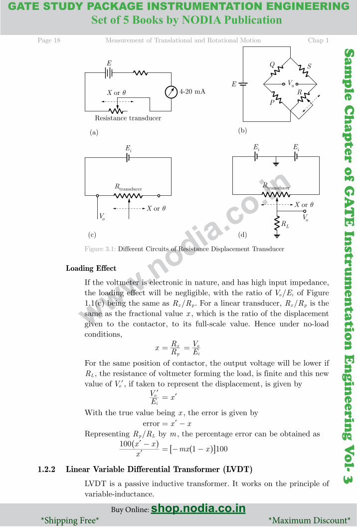
Figure 3.1 shows the different types of potentiometer circuits. Circuit (a) provides dc output currents of range 4–20 mA or any other desired range; Circuit (c) is the usual variable potential divider, also known as single-ended potentiometer circuit, Circuit (d) is a push-pull potentiometer circuit. Circuits (b) and (d) develop bipolar outputs for bidirectional motion about the central point.
Page 18 Measurement of Translational and Rotational Motion Chap 1
Buy Online: shop.nodia.co.in *Shipping Free* *Maximum Discount*
GATE STUDY PACKAGE INSTRUMENTATION ENGINEERING
Buy Online: shop.nodia.co.in *Shipping Free* *Maximum Discount*
SAlIENT FEATURES* Brief Theory * Methodology * Important Points *
*MCQ * Numerical Answer Type Questions * Memory Based Questions * Detailed Solution for Each and Every Problem*Set of 5 Books by NODIA Publication
Sam
ple
Ch
apte
r o
f G
AT
E I
nst
rum
enta
tio
n E
ngin
eeri
ng V
ol-
3
Sam
ple C
hap
ter of G
AT
E In
strum
entatio
n E
ngin
eering V
ol- 3
www.nodia.co.inFigure 3.1: Different Circuits of Resistance Displacement Transducer
Loading Effect
If the voltmeter is electronic in nature, and has high input impedance, the loading effect will be negligible, with the ratio of /V Eo i of Figure 1.1(c) being the same as /R Rx p . For a linear transducer, /R Rx p is the same as the fractional value x , which is the ratio of the displacement given to the contactor, to its full-scale value. Hence under no-load conditions,
x RRp
x= EVi
o=
For the same position of contactor, the output voltage will be lower if RL , the resistance of voltmeter forming the load, is finite and this new value of Vol, if taken to represent the displacement, is given by
EVi
ol x= l
With the true value being x , the error is given by error x x= −lRepresenting /R Rp L by m , the percentage error can be obtained as
xx x100 -ll^ h
mx x1 100= − −^ h6 @1.2.2 Linear Variable Differential Transformer (LVDT)
LVDT is a passive inductive transformer. It works on the principle of variable-inductance.

Chap 1 Measurement of Translational and Rotational Motion Page 19
Buy Online: shop.nodia.co.in *Shipping Free* *Maximum Discount*
SAlIENT FEATURES* Brief Theory * Methodology * Important Points *
*MCQ * Numerical Answer Type Questions * Memory Based Questions * Detailed Solution for Each and Every Problem*
Sam
ple
Ch
apte
r o
f G
AT
E I
nst
rum
enta
tio
n E
ngin
eeri
ng V
ol-
3
Sam
ple C
hap
ter of G
AT
E In
strum
entatio
n E
ngin
eering V
ol- 3
www.nodia.co.in
Construction of LVDT
Figure 3.2 shows the basic construction of an LVDT. The transformer consists of a single primary winding P1 and two secondary windings S1 and S2 wound on a hollow cylindrical former. The secondary windings have an equal number of turns and are identically placed on either side of the primary windings. The primary winding is connected to an ac source.
Figure 3.2: Construction of LVDT
A movable soft iron core slides within the hollow former and therefore affects the magnetic coupling between the primary and the two secondaries. The displacement to be measured is applied to an arm attached to the soft iron core. The whole assembly is placed in a stainless steel housing and the end lids provide electrostatic and electromagnetic shielding. The frequency of the ac applied to the primary winding ranges from 50 Hz to 20 kHz.
Operation of LVDT
Since the primary winding is excited by an ac source, it produces an alternating magnetic field which in turn induces ac voltages in the two secondary windings. In order to convert the output from S1 to S2 into a single voltage signal, the two secondaries S1 and S2 are connected in series opposition, as shown in Figure 3.3. Let the output voltage of the secondary winding S1 is VS1 and that of secondary winding S2 is VS2. Hence the output voltage of the transducer is the difference of the two voltages. i.e. Vo V VS S1 2= −

Page 20 Measurement of Translational and Rotational Motion Chap 1
Buy Online: shop.nodia.co.in *Shipping Free* *Maximum Discount*
GATE STUDY PACKAGE INSTRUMENTATION ENGINEERING
Buy Online: shop.nodia.co.in *Shipping Free* *Maximum Discount*
SAlIENT FEATURES* Brief Theory * Methodology * Important Points *
*MCQ * Numerical Answer Type Questions * Memory Based Questions * Detailed Solution for Each and Every Problem*Set of 5 Books by NODIA Publication
Sam
ple
Ch
apte
r o
f G
AT
E I
nst
rum
enta
tio
n E
ngin
eeri
ng V
ol-
3
Sam
ple C
hap
ter of G
AT
E In
strum
entatio
n E
ngin
eering V
ol- 3
www.nodia.co.inFigure 3.3: Measurement of Translational Motion using LVDT
When the core slides within the hollow former, the output voltage Vo will also change. The amount of voltage change will be proportional to the amount of linear motion.
ADvANTAGES OF lvDT
1. Linearity: The output voltage of this transducer is practically linear for displacement upto 5 mm.
2. High output: It gives a high output, and therefore intermediate amplification devices are not required.
3. Infinite resolution: The change in output voltage is stepless. The effective resolution depends more on the test equipment than on the transducer.
4. Ruggedness: These transducers can usually tolerate a high degree of vibration and shock.
5. Less friction: There are no sliding contacts.
6. High sensitivity: The transducer possesses a sensitivity as high as 40 V/mm.
7. Low power consumption: Most LVDTs consume less than 1W of power.
8. Low hysteresis: This transducer has a low hysteresis, hence repeatability is excellent under all conditions.
Chap 1 Measurement of Translational and Rotational Motion Page 21
Buy Online: shop.nodia.co.in *Shipping Free* *Maximum Discount*
SAlIENT FEATURES* Brief Theory * Methodology * Important Points *
*MCQ * Numerical Answer Type Questions * Memory Based Questions * Detailed Solution for Each and Every Problem*
Sam
ple
Ch
apte
r o
f G
AT
E I
nst
rum
enta
tio
n E
ngin
eeri
ng V
ol-
3
Sam
ple C
hap
ter of G
AT
E In
strum
entatio
n E
ngin
eering V
ol- 3
www.nodia.co.in
DISADvANTAGES OF lvDT
1. Large displacements are required for appreciable differential output.
2. They are sensitive to stray magnetic fields.
3. The receiving instrument must be selected to operate on ac signals, or a demodulator network must be used if a dc output is required.
4. The dynamic response is limited mechanically by the mass of the core and electrically by the applied voltage.
5. Temperature also affects the transducer.
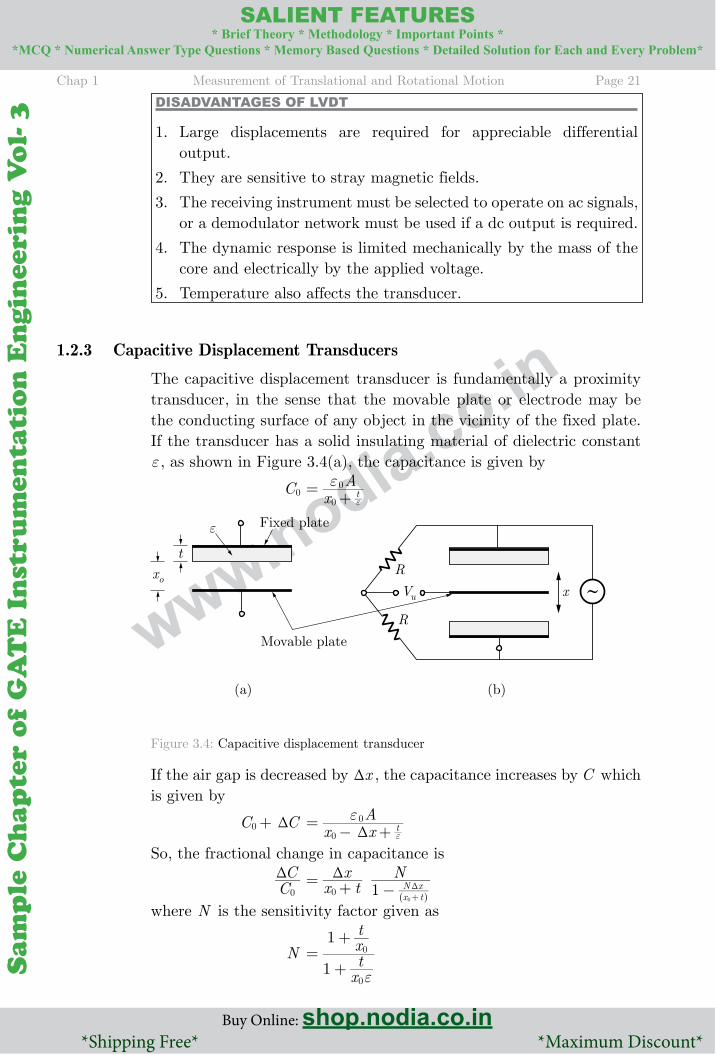
1.2.3 Capacitive Displacement Transducers
The capacitive displacement transducer is fundamentally a proximity transducer, in the sense that the movable plate or electrode may be the conducting surface of any object in the vicinity of the fixed plate. If the transducer has a solid insulating material of dielectric constant ε , as shown in Figure 3.4(a), the capacitance is given by
C0 xAt
0
0ε =+ ε
Figure 3.4: Capacitive displacement transducer
If the air gap is decreased by xT , the capacitance increases by C which is given by
C C0 T+ x x
At
0
0
Tε =
− + ε
So, the fractional change in capacitance is
CC0
T x tx N1 x t
N x0
0
T= + − T+^ h
where N is the sensitivity factor given as
N
xtxt
1
1
0
0
ε =
+
+
Page 22 Measurement of Translational and Rotational Motion Chap 1
Buy Online: shop.nodia.co.in *Shipping Free* *Maximum Discount*
GATE STUDY PACKAGE INSTRUMENTATION ENGINEERING
Buy Online: shop.nodia.co.in *Shipping Free* *Maximum Discount*
SAlIENT FEATURES* Brief Theory * Methodology * Important Points *
*MCQ * Numerical Answer Type Questions * Memory Based Questions * Detailed Solution for Each and Every Problem*Set of 5 Books by NODIA Publication
Sam
ple
Ch
apte
r o
f G
AT
E I
nst
rum
enta
tio
n E
ngin
eeri
ng V
ol-
3
Sam
ple C
hap
ter of G
AT
E In
strum
entatio
n E
ngin
eering V
ol- 3
www.nodia.co.in
1.3 MEASUREMENT OF TRANSlATIONAl vElOCITY
Translational velocity cannot be measured directly and therefore must be calculated indirectly by other means as described below.
1.3.1 Differentiation of Displacement Measurements
Differentiation of position measurements obtained from any of the translational displacement transducers described in previous section can be used to produce a translational velocity signal. Unfortunately, the process of differentiation always amplifies noise in a measurement system. Therefore, if this method has to be used, a low-noise instrument such as a d.c. excited carbon film potentiometer or laser interferometer should be chosen. In the case of potentiometers, a.c. excitation must be avoided because of the problem that harmonics in the power supply would cause.
1.3.2 Integration of the Output of an Accelerometer
Where an accelerometer is already included within a system, integration of its output can be performed to yield a velocity signal. The process of integration attenuates rather than amplifies measurement noise and this is therefore an acceptable technique.
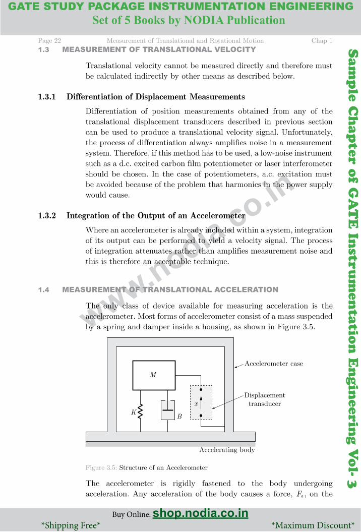
1.4 MEASUREMENT OF TRANSlATIONAl ACCElERATION
The only class of device available for measuring acceleration is the accelerometer. Most forms of accelerometer consist of a mass suspended by a spring and damper inside a housing, as shown in Figure 3.5.
Figure 3.5: Structure of an Accelerometer
The accelerometer is rigidly fastened to the body undergoing acceleration. Any acceleration of the body causes a force, Fa , on the
Chap 1 Measurement of Translational and Rotational Motion Page 23
Buy Online: shop.nodia.co.in *Shipping Free* *Maximum Discount*
SAlIENT FEATURES* Brief Theory * Methodology * Important Points *
*MCQ * Numerical Answer Type Questions * Memory Based Questions * Detailed Solution for Each and Every Problem*
Sam
ple
Ch
apte
r o
f G
AT
E I
nst
rum
enta
tio
n E
ngin
eeri
ng V
ol-
3
Sam
ple C
hap
ter of G
AT
E In
strum
entatio
n E
ngin
eering V
ol- 3
www.nodia.co.in
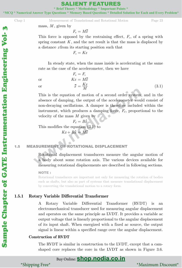
mass, M , given by Fa Mx= p
This force is opposed by the restraining effect, Fs , of a spring with spring constant K , and the net result is that the mass is displaced by a distance x from its starting position such that Fs Kx=
In steady state, when the mass inside is accelerating at the same rate as the case of the accelerometer, then we have Fa Fs=or Kx Mx= p
or xp MKx= (3.1)
This is the equation of motion of a second order system, and in the absence of damping, the output of the accelerometer would consist of non-decaying oscillations. A damper is therefore included within the instrument, which produces a damping force, Fd , proportional to the velocity of the mass M given by Fd Bx= o
This modifies the equation (3.1) to Kx Bx+ o Mx= p
1.5 MEASUREMENT OF ROTATIONAl DISPlACEMENT
Rotational displacement transducers measure the angular motion of a body about some rotation axis. The various devices available for measuring rotational displacements are described in following sections.
NOTE Rotational transducers are important not only for measuring the rotation of bodies such as shafts, but also as part of systems that measure translational displacement by converting the translational motion to a rotary form.
1.5.1 Rotary Variable Differential Transformer
A Rotary Variable Differential Transformer (RVDT) is an electromechanical transducer used for measuring angular displacement and operates on the same principle as LVDT. It provides a variable ac output voltage that is linearly proportional to the angular displacement of its input shaft. When energized with a fixed ac source, the output signal is linear within a specified range over the angular displacement.
Construction of RVDT
The RVDT is similar in construction to the LVDT, except that a cam-shaped core replaces the core in the LVDT as shown in Figure 3.6.
Page 24 Measurement of Translational and Rotational Motion Chap 1
Buy Online: shop.nodia.co.in *Shipping Free* *Maximum Discount*
GATE STUDY PACKAGE INSTRUMENTATION ENGINEERING
Buy Online: shop.nodia.co.in *Shipping Free* *Maximum Discount*
SAlIENT FEATURES* Brief Theory * Methodology * Important Points *
*MCQ * Numerical Answer Type Questions * Memory Based Questions * Detailed Solution for Each and Every Problem*Set of 5 Books by NODIA Publication
Sam
ple
Ch
apte
r o
f G
AT
E I
nst
rum
enta
tio
n E
ngin
eeri
ng V
ol-
3
Sam
ple C
hap
ter of G
AT
E In
strum
entatio
n E
ngin
eering V
ol- 3
www.nodia.co.in
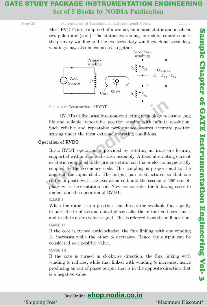
Most RVDTs are composed of a wound, laminated stator and a salient two-pole rotor (core). The stator, containing four slots, contains both the primary winding and the two secondary windings. Some secondary windings may also be connected together.
Figure 3.6: Construction of RVDT
RVDTs utilize brushless, non-contacting technology to ensure long life and reliable, repeatable position sensing with infinite resolution. Such reliable and repeatable performance assures accurate position sensing under the most extreme operating conditions.
Operation of RVDT
Basic RVDT operation is provided by rotating an iron-core bearing supported within a housed stator assembly. A fixed alternating current excitation is applied to the primary stator coil that is electromagnetically coupled to the secondary coils. This coupling is proportional to the angle of the input shaft. The output pair is structured so that one coil is in-phase with the excitation coil, and the second is 180c out-of-phase with the excitation coil. Now, we consider the following cases to understand the operation of RVDT:
CASE IWhen the rotor is in a position that directs the available flux equally in both the in-phase and out-of-phase coils, the output voltages cancel and result in a zero values signal. This is referred to as the null position.
CASE IIIf the core is turned anticlockwise, the flux linking with one winding S1, increases while the other S2 decreases. Hence the output can be considered as a positive value.
CASE IIIIf the core is turned in clockwise direction, the flux linking with winding S1 reduces, while that linked with winding S2 increases, hence producing an out of phase output that is in the opposite direction that is a negative value.
Chap 1 Measurement of Translational and Rotational Motion Page 25
Buy Online: shop.nodia.co.in *Shipping Free* *Maximum Discount*
SAlIENT FEATURES* Brief Theory * Methodology * Important Points *
*MCQ * Numerical Answer Type Questions * Memory Based Questions * Detailed Solution for Each and Every Problem*
Sam
ple
Ch
apte
r o
f G
AT
E I
nst
rum
enta
tio
n E
ngin
eeri
ng V
ol-
3
Sam
ple C
hap
ter of G
AT
E In
strum
entatio
n E
ngin
eering V
ol- 3
www.nodia.co.in
1.6 MEASUREMENT OF ROTATIONAl vElOCITY
The main application of rotational velocity transducers is in speed control systems. They also provide the usual means of measuring translational velocities, which are transformed into rotational motions for measurement purposes by suitable gearing. Many different instruments and techniques are available for measuring rotational velocity as presented below.
1.6.1 Digital Tachometers
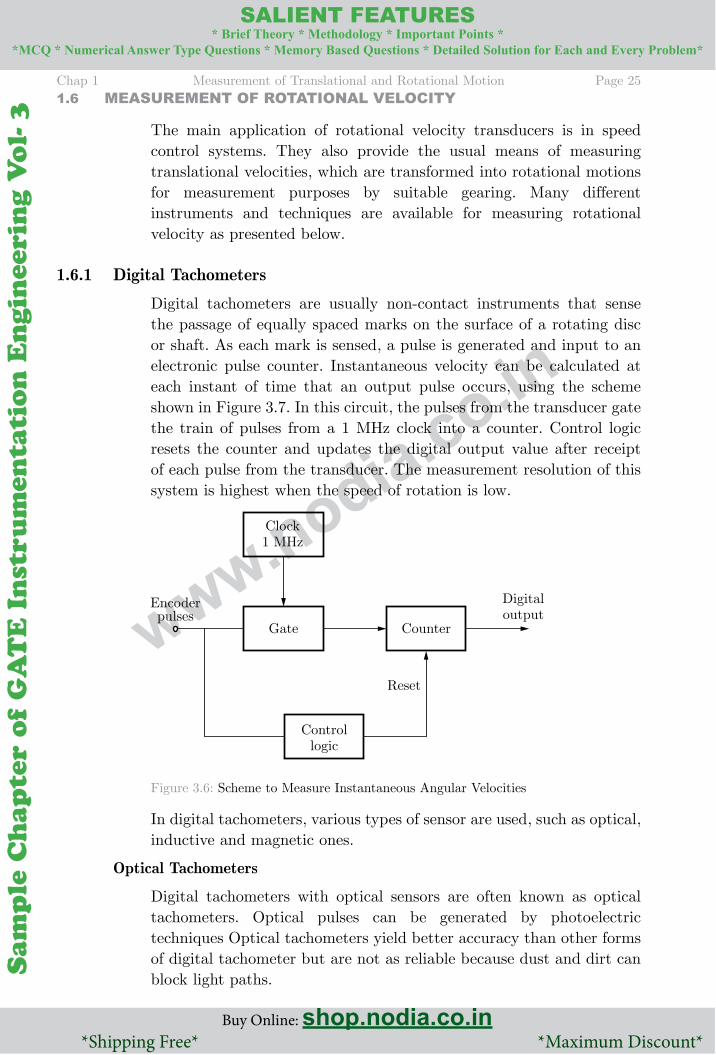
Digital tachometers are usually non-contact instruments that sense the passage of equally spaced marks on the surface of a rotating disc or shaft. As each mark is sensed, a pulse is generated and input to an electronic pulse counter. Instantaneous velocity can be calculated at each instant of time that an output pulse occurs, using the scheme shown in Figure 3.7. In this circuit, the pulses from the transducer gate the train of pulses from a 1 MHz clock into a counter. Control logic resets the counter and updates the digital output value after receipt of each pulse from the transducer. The measurement resolution of this system is highest when the speed of rotation is low.
Figure 3.6: Scheme to Measure Instantaneous Angular Velocities
In digital tachometers, various types of sensor are used, such as optical, inductive and magnetic ones.
Optical Tachometers
Digital tachometers with optical sensors are often known as optical tachometers. Optical pulses can be generated by photoelectric techniques Optical tachometers yield better accuracy than other forms of digital tachometer but are not as reliable because dust and dirt can block light paths.

Page 26 Measurement of Translational and Rotational Motion Chap 1
Buy Online: shop.nodia.co.in *Shipping Free* *Maximum Discount*
GATE STUDY PACKAGE INSTRUMENTATION ENGINEERING
Buy Online: shop.nodia.co.in *Shipping Free* *Maximum Discount*
SAlIENT FEATURES* Brief Theory * Methodology * Important Points *
*MCQ * Numerical Answer Type Questions * Memory Based Questions * Detailed Solution for Each and Every Problem*Set of 5 Books by NODIA Publication
Sam
ple
Ch
apte
r o
f G
AT
E I
nst
rum
enta
tio
n E
ngin
eeri
ng V
ol-
3
Sam
ple C
hap
ter of G
AT
E In
strum
entatio
n E
ngin
eering V
ol- 3
www.nodia.co.in
Induction Tachometers
Induction tachometers are a form of digital tachometer that use inductive sensing. They are widely used in the automotive industry within anti-skid devices, anti-lock braking systems (ABS) and traction control.
Magnetostricitive Tachometers
The rotating element in magnetostrictive tachometers has a very simple design in the form of a toothed metal gearwheel. The sensor is a solid-state, Hall-effect device that is placed between the gear wheel and a permanent magnet. When an inter-tooth gap on the gear wheel is adjacent to the sensor, the full magnetic field from the magnet passes through it. Later, as a tooth approaches the sensor, the tooth diverts some of the magnetic field, and so the field through the sensor is reduced. This causes the sensor to produce an output voltage that is proportional to the rotational speed of the gear wheel.
1.6.2 Analogue Tachometers
Analogue tachometers are less accurate than digital tachometers but are nevertheless still used successfully in many applications. The a.c. tachometer has an output approximately proportional to rotational speed like, the d.c. tachogenerator. Mechanical structure of an analogue tachometer takes the form of a two-phase induction motor, with two stator windings and (usually) a drag-cup rotor, as shown in Figure 3.7.
Figure 3.7: Working of AC Tachometer
One of the stator windings is excited with an a.c. voltage and the measurement signal is taken from the output voltage induced in the second winding. The magnitude of this output voltage is zero when the rotor is stationary, and otherwise proportional to the angular velocity of the rotor. The direction of rotation is determined by the phase of the output voltage, which switches by 180° as the direction reverses.
Chap 1 Measurement of Translational and Rotational Motion Page 27
Buy Online: shop.nodia.co.in *Shipping Free* *Maximum Discount*
SAlIENT FEATURES* Brief Theory * Methodology * Important Points *
*MCQ * Numerical Answer Type Questions * Memory Based Questions * Detailed Solution for Each and Every Problem*
Sam
ple
Ch
apte
r o
f G
AT
E I
nst
rum
enta
tio
n E
ngin
eeri
ng V
ol-
3
Sam
ple C
hap
ter of G
AT
E In
strum
entatio
n E
ngin
eering V
ol- 3
www.nodia.co.in
Therefore, both the phase and magnitude of the output voltage have to be measured.
1.6.3 Differentiation of Angular Displacement Measurements
Angular velocity measurements can be obtained by differentiating the output signal from angular displacement transducers. Unfortunately, the process of differentiation amplifies any noise in the measurement signal.
1.6.4 Integration of the Output From an Accelerometer
In measurement systems that already contain an angular acceleration transducer, it is possible to obtain a velocity measurement by integrating the acceleration measurement signal. This produces a signal of acceptable quality, as the process of integration attenuates any measurement noise.
1.7 MEASUREMENT OF ROTATIONAl ACCElERATION
Rotational accelerometers work on very similar principles to translational motion accelerometers. They consist of a rotatable mass mounted inside a housing that is attached to the accelerating, rotating body. Rotation of the mass is opposed by a torsional spring and damping. Any acceleration of the housing causes a torque Jθ p on the mass. This torque is opposed by a backward torque due to the torsional spring and in equilibrium Jθ p Kθ =
or θ p JKθ =
A damper is usually included in the systems to avoid undying oscillations in the instrument. This adds an additional backward torque Bθ o to the system and the equation of motion becomes Jθ p B Kq q= +o
1.8 MEASUREMENT OF vIBRATION
Vibrations are very commonly encountered in machinery operation, and therefore measurement of the accelerations associated with such vibrations is extremely important in industrial environments. Vibrations normally consist of linear harmonic motion that can be expressed mathematically as X ( )sinX t0 ω =
Page 28 Measurement of Translational and Rotational Motion Chap 1
Buy Online: shop.nodia.co.in *Shipping Free* *Maximum Discount*
GATE STUDY PACKAGE INSTRUMENTATION ENGINEERING
Buy Online: shop.nodia.co.in *Shipping Free* *Maximum Discount*
SAlIENT FEATURES* Brief Theory * Methodology * Important Points *
*MCQ * Numerical Answer Type Questions * Memory Based Questions * Detailed Solution for Each and Every Problem*Set of 5 Books by NODIA Publication
Sam
ple
Ch
apte
r o
f G
AT
E I
nst
rum
enta
tio
n E
ngin
eeri
ng V
ol-
3
Sam
ple C
hap
ter of G
AT
E In
strum
entatio
n E
ngin
eering V
ol- 3
www.nodia.co.in
where X is the displacement from the equilibrium position at any general point in time, X0 is the peak displacement from the equilibrium position, and ω is the angular frequency of the oscillations. The velocity v of the vibrating body can be obtained as v ( )cosX t0w w=and expression for the acceleration can be given as α ( )sin t2
0w w=−It is apparent that the intensity of vibration can be measured in terms of either displacement, velocity or acceleration. Acceleration is clearly the best parameter to measure at high frequencies. However, because displacements are large at low frequencies, it would seem that measuring either displacement or velocity would be best at low frequencies. In next section, we will learn the technique of vibration measurement.
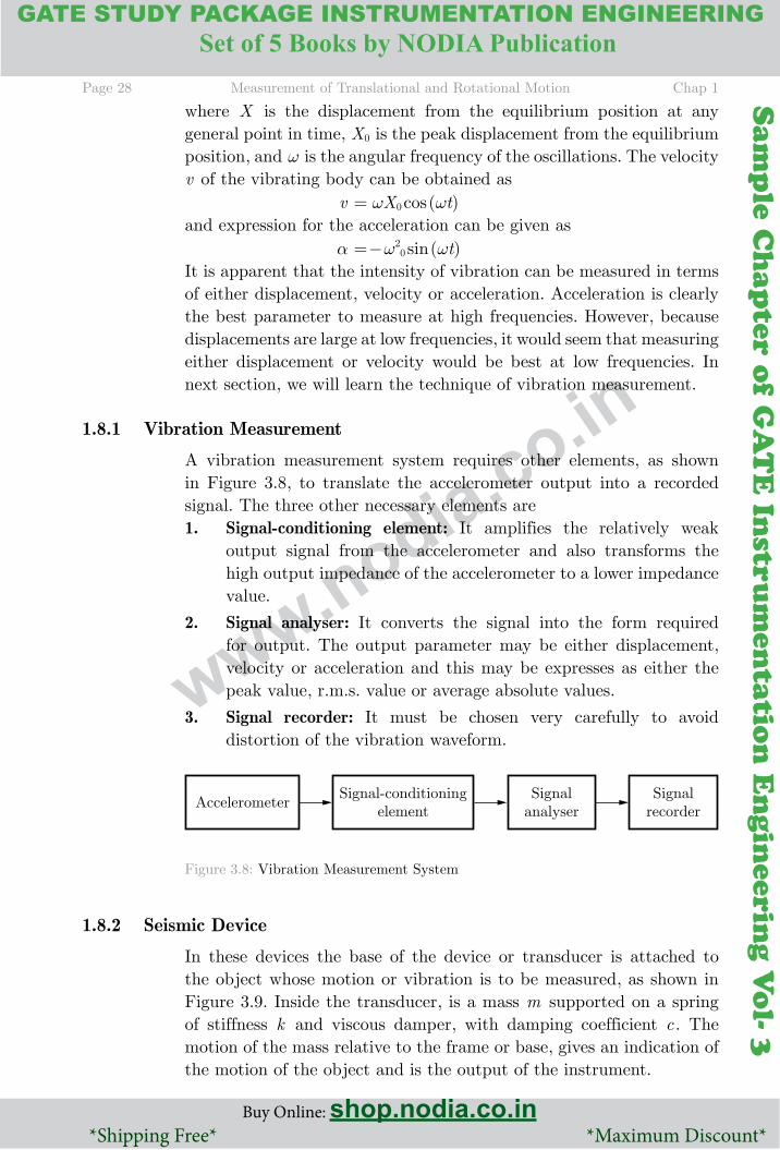
1.8.1 Vibration Measurement
A vibration measurement system requires other elements, as shown in Figure 3.8, to translate the accelerometer output into a recorded signal. The three other necessary elements are1. Signal-conditioning element: It amplifies the relatively weak
output signal from the accelerometer and also transforms the high output impedance of the accelerometer to a lower impedance value.
2. Signal analyser: It converts the signal into the form required for output. The output parameter may be either displacement, velocity or acceleration and this may be expresses as either the peak value, r.m.s. value or average absolute values.
3. Signal recorder: It must be chosen very carefully to avoid distortion of the vibration waveform.
Figure 3.8: Vibration Measurement System
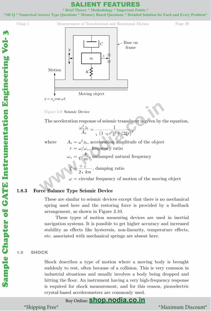
1.8.2 Seismic Device
In these devices the base of the device or transducer is attached to the object whose motion or vibration is to be measured, as shown in Figure 3.9. Inside the transducer, is a mass m supported on a spring of stiffness k and viscous damper, with damping coefficient c . The motion of the mass relative to the frame or base, gives an indication of the motion of the object and is the output of the instrument.
Chap 1 Measurement of Translational and Rotational Motion Page 29
Buy Online: shop.nodia.co.in *Shipping Free* *Maximum Discount*
SAlIENT FEATURES* Brief Theory * Methodology * Important Points *
*MCQ * Numerical Answer Type Questions * Memory Based Questions * Detailed Solution for Each and Every Problem*
Sam
ple
Ch
apte
r o
f G
AT
E I
nst
rum
enta
tio
n E
ngin
eeri
ng V
ol-
3
Sam
ple C
hap
ter of G
AT
E In
strum
entatio
n E
ngin
eering V
ol- 3
www.nodia.co.inFigure 3.9: Seismic Device
The acceleration response of seismic transducer is given by the equation,
Azn0
20ω
( ) ( )r r1 212 2 2ξ
=− +
where A0 x2 0ω = , acceleration amplitude of the object r / nw w= , frequency ratio
nω mk= , undamped natural frequency
ξ kmc
2= , damping ratio
ω = circular frequency of motion of the moving object
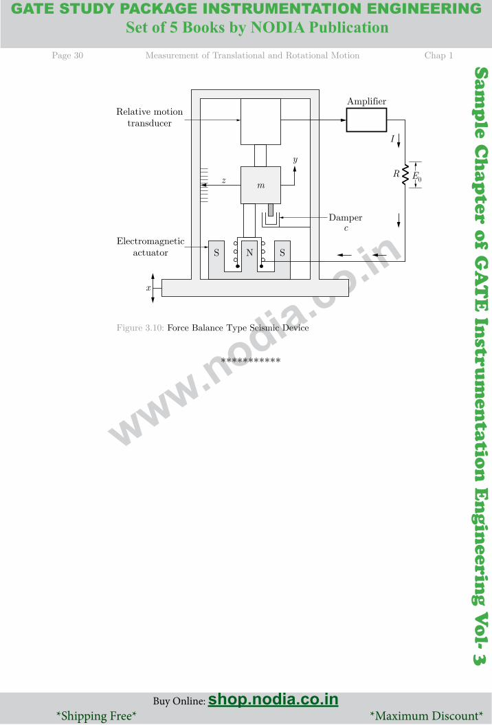
1.8.3 Force Balance Type Seismic Device
These are similar to seismic devices except that there is no mechanical spring used here and the restoring force is provided by a feedback arrangement, as shown in Figure 3.10.
These types of motion measuring devices are used in inertial navigation systems. It is possible to get higher accuracy and increased stability as effects like hysteresis, non-linearity, temperature effects, etc. associated with mechanical springs are absent here.
1.9 ShOCK
Shock describes a type of motion where a moving body is brought suddenly to rest, often because of a collision. This is very common in industrial situations and usually involves a body being dropped and hitting the floor. An instrument having a very high-frequency response is required for shock measurement, and for this reason, piezoelectric crystal-based accelerometers are commonly used.
Page 30 Measurement of Translational and Rotational Motion Chap 1
Buy Online: shop.nodia.co.in *Shipping Free* *Maximum Discount*
GATE STUDY PACKAGE INSTRUMENTATION ENGINEERING
Buy Online: shop.nodia.co.in *Shipping Free* *Maximum Discount*
SAlIENT FEATURES* Brief Theory * Methodology * Important Points *
*MCQ * Numerical Answer Type Questions * Memory Based Questions * Detailed Solution for Each and Every Problem*Set of 5 Books by NODIA Publication
Sam
ple
Ch
apte
r o
f G
AT
E I
nst
rum
enta
tio
n E
ngin
eeri
ng V
ol-
3
Sam
ple C
hap
ter of G
AT
E In
strum
entatio
n E
ngin
eering V
ol- 3
www.nodia.co.inFigure 3.10: Force Balance Type Seismic Device
Chap 1 Measurement of Translational and Rotational Motion Page 31
Buy Online: shop.nodia.co.in *Shipping Free* *Maximum Discount*
SAlIENT FEATURES* Brief Theory * Methodology * Important Points *
*MCQ * Numerical Answer Type Questions * Memory Based Questions * Detailed Solution for Each and Every Problem*
Sam
ple
Ch
apte
r o
f G
AT
E I
nst
rum
enta
tio
n E
ngin
eeri
ng V
ol-
3
Sam
ple C
hap
ter of G
AT
E In
strum
entatio
n E
ngin
eering V
ol- 3
www.nodia.co.in
EEERCISE
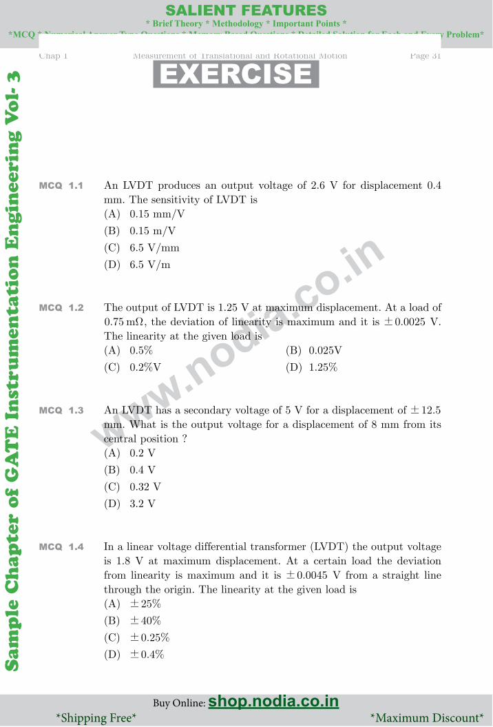
MCQ 1.1 An LVDT produces an output voltage of 2.6 V for displacement 0.4 mm. The sensitivity of LVDT is(A) 0.15 mm/V
(B) 0.15 m/V
(C) 6.5 V/mm
(D) 6.5 V/m
MCQ 1.2 The output of LVDT is 1.25 V at maximum displacement. At a load of . m0 75 Ω , the deviation of linearity is maximum and it is .0 0025! V.
The linearity at the given load is(A) 0.5% (B) 0.025V
(C) 0.2%V (D) 1.25%
MCQ 1.3 An LVDT has a secondary voltage of 5 V for a displacement of .12 5! mm. What is the output voltage for a displacement of 8 mm from its central position ?(A) 0.2 V
(B) 0.4 V
(C) 0.32 V
(D) 3.2 V
MCQ 1.4 In a linear voltage differential transformer (LVDT) the output voltage is 1.8 V at maximum displacement. At a certain load the deviation from linearity is maximum and it is .0 0045! V from a straight line through the origin. The linearity at the given load is(A) %25!
(B) %40!
(C) . %0 25!
(D) . %0 4!
Page 32 Measurement of Translational and Rotational Motion Chap 1
Buy Online: shop.nodia.co.in *Shipping Free* *Maximum Discount*
GATE STUDY PACKAGE INSTRUMENTATION ENGINEERING
Buy Online: shop.nodia.co.in *Shipping Free* *Maximum Discount*
SAlIENT FEATURES* Brief Theory * Methodology * Important Points *
*MCQ * Numerical Answer Type Questions * Memory Based Questions * Detailed Solution for Each and Every Problem*Set of 5 Books by NODIA Publication
Sam
ple
Ch
apte
r o
f G
AT
E I
nst
rum
enta
tio
n E
ngin
eeri
ng V
ol-
3
Sam
ple C
hap
ter of G
AT
E In
strum
entatio
n E
ngin
eering V
ol- 3
www.nodia.co.in
NAT 1.5 The output of an LVDT is connected to a 4 V voltmeter through an amplifier whose amplification factor is 500. An output of 1.8 mV appears across the terminals of LVDT when the core moves through a distance of 0.6 mm. If the millivoltmeter scale has 100 divisions and the scale can be read to 4
1 of a division, then the resolution of instrument will be
mm
MCQ 1.6 An LVDT is used for measuring the deflection of a bellows. The sensitivity of LVDT is 40 V per mm. The bellows is deflected by 0.125 mm by a pressure of . /N m0 8 106 2
# . The sensitivity of the LVDT in V per /N m2 is(A) 4 10 6#
-
(B) .6 25 10 6#-
(C) 5 10 6#-
(D) .1 25 10 6#-
NAT 1.7 The output of an LVDT is connected to a 5V voltmeter through an amplifier with a gain of 250. The voltmeter scale has 100 divisions and the scale can be read upto 1/5th of a division. An output of 2 mV appears across the terminals of the LVDT, when core is displaced through a distance of 0.5 mm. The resolution of instrument is
m
MCQ 1.8 The output of an LVDT is connected to a 5 V voltmeter through an amplifier whose amplification factor is 250. An output of 2 mV appears across the terminals of LVDT when the core moves through a distance of 0.5 mm. The millivoltmeter scale has 100 divisions. The scale can be read to 5
1 of a division. The resolution of the instrument in mm is(A) 10 3- (B) 10 4-
(C) 10 2- (D) None of these
NAT 1.9 An accelerometer has a seismic mass of 0.05 kg and a spring constant of 3 103# N/m. Maximum mass displacement is .0 02! m (before the mass hits the stop). The maximum measurable acceleration is
Chap 1 Measurement of Translational and Rotational Motion Page 33
Buy Online: shop.nodia.co.in *Shipping Free* *Maximum Discount*
SAlIENT FEATURES* Brief Theory * Methodology * Important Points *
*MCQ * Numerical Answer Type Questions * Memory Based Questions * Detailed Solution for Each and Every Problem*
Sam
ple
Ch
apte
r o
f G
AT
E I
nst
rum
enta
tio
n E
ngin
eeri
ng V
ol-
3
Sam
ple C
hap
ter of G
AT
E In
strum
entatio
n E
ngin
eering V
ol- 3
www.nodia.co.in
NAT 1.10 A seismic instrument has a natural frequency of 4 Hz and a damping ratio of 0.66. If the system is excited by a frequency 6 Hz, the error due to the proximity of excited frequency with natural frequency of the instrument will be
%
MCQ 1.11 A steel cantilever is 0.25 m long, 15 mm wide, and 3 mm thick. The modulus of elasticity for steel is /GN m200 2. When a force of 22 N is applied at the free end, the value of deflection at the end will be(A) 16.975 (B) 9.21
(C) 0.0589 (D) 33.75
MCQ 1.12 A body is dropped from a height of 10 m and suffers a shock when it hits the ground. If the duration of the shock is 5 ms, the magnitude of the shock will be (g is acceleration due to gravity)(A) g7
(B) g200
(C) g286
(D) None of these
MCQ 1.13 A variable reluctance type tachometer has 120 teeth on rotor. The speed of the shaft on which the rotor is mounted is 1500 rpm. What will be the frequency of the output pulses ?(A) 25 pulse per second (B) 3000 pulses per second
(C) 2 pulses per second (D) None of these
MCQ 1.14 A toothed rotor tachometer is used with a digital counter for measuring speed of rotation of the shaft on which the wheel is mounted. The gating period is s103 µ and a reading of 0004 is obtained on the four digit display. If the number of teeth on rotor is 150, then the speed of shaft is(A) 150
(B) 4000
(C) 1600
(D) 100
Page 34 Measurement of Translational and Rotational Motion Chap 1
Buy Online: shop.nodia.co.in *Shipping Free* *Maximum Discount*
GATE STUDY PACKAGE INSTRUMENTATION ENGINEERING
Buy Online: shop.nodia.co.in *Shipping Free* *Maximum Discount*
SAlIENT FEATURES* Brief Theory * Methodology * Important Points *
*MCQ * Numerical Answer Type Questions * Memory Based Questions * Detailed Solution for Each and Every Problem*Set of 5 Books by NODIA Publication
Sam
ple
Ch
apte
r o
f G
AT
E I
nst
rum
enta
tio
n E
ngin
eeri
ng V
ol-
3
Sam
ple C
hap
ter of G
AT
E In
strum
entatio
n E
ngin
eering V
ol- 3
www.nodia.co.in
NAT 1.15 The frequency of the flashes of a stroboscope is adjusted such that a disc with 20 points mounted on the shaft of the machine seems to be at standstill. If the adjusted frequency of the flashes is 5000 per minute and approximate speed of the machine is 765 rpm given by the other method, then the correct speed of the machine is
rpm
MCQ 1.16 The speed of a 6-pole induction motor supplied at 50 Hz is measured by a stroboscopic method. The neon lamp is supplied from the same source to which the induction motor is connected. The stroboscopic disc has six black and six white sectors. What will be the speed of the induction motor when the sector appears to be moving at 50 rpm ?(A) 1000 rpm
(B) 50 rpm
(C) 950 rpm
(D) 1050 rpm
NAT 1.17 An accelerometer has a seismic mass of 0.06 kg and a spring constant of 4500 N/m. Maximum mass displacement is .0 025! m (before the mass hits the top). The maximum measurable acceleration is
/m s2
MCQ 1.18 In an LVDT accelerometer the outputs are 0.4 mV/mm with a 25! mm core displacement. The spring constant is 300 N/m and the mass of the core is 50g. What is sensitivity of the accelerometer ?(A) /ms mV15 2- (B) /ms mV150 2-
(C) . /ms mV0 66 2- (D) None of these
NAT 1.19 A variable reluctance type tachometer has 60 rotor teeth. The counter records 3600 counts per second. The speed in rpm is
MCQ 1.20 An inductive pickoff operating from a 120 tooth wheel is used with a digital frequency meter to measure the speed of rotation of the shaft on which the wheel is mounted. The gating period is set to s104 µ , and a reading of 0030 is obtained on the four digit display. If the
Chap 1 Measurement of Translational and Rotational Motion Page 35
Buy Online: shop.nodia.co.in *Shipping Free* *Maximum Discount*
SAlIENT FEATURES* Brief Theory * Methodology * Important Points *
*MCQ * Numerical Answer Type Questions * Memory Based Questions * Detailed Solution for Each and Every Problem*
Sam
ple
Ch
apte
r o
f G
AT
E I
nst
rum
enta
tio
n E
ngin
eeri
ng V
ol-
3
Sam
ple C
hap
ter of G
AT
E In
strum
entatio
n E
ngin
eering V
ol- 3
www.nodia.co.in
available gating periods are 102, 103, 104, 105, 106, 107 sµ respectively, what would be the optimum setting of gating period for making this measurement ?(A) s104 µ (B) s105 µ
(C) s106 µ (D) s102 µ
MCQ 1.21 While measuring speed of a steam turbine with stroboscope single line images were observed for stroboscope setting of 3000, 4000 and 5230 rpm. What is the speed of the turbine ?(A) 6000 rpm
(B) 700 rpm
(C) 12000 rpm
(D) 14000 rpm
MCQ 1.22 A disc mounted on the shaft of a machine has 12 pattern points. The number of flashes projected on the disc by a stroboscope is 6000 in a minute. If the disc appears to move forward in the direction of rotation at 10 rpm, the speed of the disc is(A) 500 rpm
(B) 490 rpm
(C) 510 rpm
(D) 5000 rpm
MCQ 1.23 A displacement transducer with a shaft stroke of 3.0 inch is applied to the circuit shown in figure below. The total resistance of the potentiometer is k5 Ω . The applied voltage Vt is 5.0 V. When the wiper is 0.9 inch from B , what will be the value of the output voltage ?(A) 0.66 V
(B) 1500 V
(C) 1.5 V
(D) 66.6 V
NAT 1.24 A linear resistance potentiometer is 50 mm long and is uniformly wound with a wire of total resistance 5000Ω . Under normal conditions the slider is at the centre of the potentiometer. When the resistance of the potentiometer is 1850Ω , the linear displacement will be
mm
Page 36 Measurement of Translational and Rotational Motion Chap 1
Buy Online: shop.nodia.co.in *Shipping Free* *Maximum Discount*
GATE STUDY PACKAGE INSTRUMENTATION ENGINEERING
Buy Online: shop.nodia.co.in *Shipping Free* *Maximum Discount*
SAlIENT FEATURES* Brief Theory * Methodology * Important Points *
*MCQ * Numerical Answer Type Questions * Memory Based Questions * Detailed Solution for Each and Every Problem*Set of 5 Books by NODIA Publication
Sam
ple
Ch
apte
r o
f G
AT
E I
nst
rum
enta
tio
n E
ngin
eeri
ng V
ol-
3
Sam
ple C
hap
ter of G
AT
E In
strum
entatio
n E
ngin
eering V
ol- 3
www.nodia.co.in
NAT 1.25 A linear resistance potentiometer is 50 mm long and is uniformly wound with a wire of total resistance ,5 000Ω . Under normal conditions, the slider is at the centre of the potentiometer. When the resistance of the potentiometer, as measured by the Wheatstone bridge, is 1850Ω , the linear displacement is
mm
MCQ 1.26 A linear resistance potentiometer is 50 mm long and is uniformly wound with a wire having a resistance of 10000Ω . Under normal conditions, the slider is at the centre of the potentiometer. For the linear displacements x and y the resistance of the potentiometer as measured by a Wheatstone bridge are respectively 3850Ω and 7560Ω . Which of the following is/are correct ?(A) . mx 5 75=
(B) . my 12 8=
(C) Displacements x and y are in opposite direction
(D) All of the above
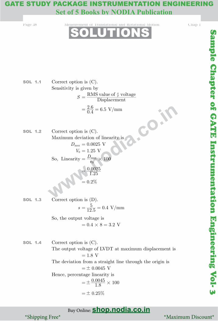
NAT 1.27 A resistive potential divider R R1 2 with a resistance of 5000Ω and a shaft stroke of 125 mm is used in the arrangement shown in figure below. Potentiometer R R3 4 has a resistance of 5000Ω and . Ve 5 0i = . The initial position to be used as reference point is such that R R1 2= i.e. the wiper is at midstroke. At the start of the test potentiometer R R3 4 is adjusted so that the bridge is balanced and e 00 = . Assuming that the displacement being measured will move a maximum distance of 12.5 mm towards A, the value of e0 will be
Volt

Chap 1 Measurement of Translational and Rotational Motion Page 37
Buy Online: shop.nodia.co.in *Shipping Free* *Maximum Discount*
SAlIENT FEATURES* Brief Theory * Methodology * Important Points *
*MCQ * Numerical Answer Type Questions * Memory Based Questions * Detailed Solution for Each and Every Problem*
Sam
ple
Ch
apte
r o
f G
AT
E I
nst
rum
enta
tio
n E
ngin
eeri
ng V
ol-
3
Sam
ple C
hap
ter of G
AT
E In
strum
entatio
n E
ngin
eering V
ol- 3
www.nodia.co.in
MCQ 1.28 A resistive transducer with a resistance of k5 Ω and a shaft stroke of 3.0 cm is used in the arrangement shown below. Potentiometer R3-R4 is also k5 and Vt is 5.0 V. The initial position to be used as a reference point is such that R R1 2= (i.e. the shaft is at the centre) At the start of the test, potentiometer R3-R4 is adjusted so that the bridge is balanced V 0e =^ h. If we assume that the object being monitored moves a maximum resistance of 0.5 cm towards A, then what will be the new value of Vc ? (shaft distance is 5 cm)(A) 0.5 V
(B) 2.5 V
(C) 3 V
(D) 5.5 V
Page 38 Measurement of Translational and Rotational Motion Chap 1
Buy Online: shop.nodia.co.in *Shipping Free* *Maximum Discount*
GATE STUDY PACKAGE INSTRUMENTATION ENGINEERING
Buy Online: shop.nodia.co.in *Shipping Free* *Maximum Discount*
SAlIENT FEATURES* Brief Theory * Methodology * Important Points *
*MCQ * Numerical Answer Type Questions * Memory Based Questions * Detailed Solution for Each and Every Problem*Set of 5 Books by NODIA Publication
Sam
ple
Ch
apte
r o
f G
AT
E I
nst
rum
enta
tio
n E
ngin
eeri
ng V
ol-
3
Sam
ple C
hap
ter of G
AT
E In
strum
entatio
n E
ngin
eering V
ol- 3
www.nodia.co.in
SOlUTIONS
SOl 1.1 Correct option is (C).Sensitivity is given by
S DisplacementRMS value of voltagep
o
=
.. .0 42 6 6 5= = V/mm
SOl 1.2 Correct option is (C).Maximum deviation of linearity is Dmax .0 0025= V V0 .1 25= V
So, Linearity vD 100max
0#=
..1 250 0025=
. %0 2=
SOl 1.3 Correct option is (D).
s . .12 55 0 4= = V/mm
So, the output voltage is . .0 4 8 3 2#= = V
SOl 1.4 Correct option is (C).The output voltage of LVDT at maximum displacement is .1 8= VThe deviation from a straight line through the origin is .0 0045!= VHence, percentage linearity is
..1 80 0045 100! #=
. %0 25!=
Chap 1 Measurement of Translational and Rotational Motion Page 39
Buy Online: shop.nodia.co.in *Shipping Free* *Maximum Discount*
SAlIENT FEATURES* Brief Theory * Methodology * Important Points *
*MCQ * Numerical Answer Type Questions * Memory Based Questions * Detailed Solution for Each and Every Problem*
Sam
ple
Ch
apte
r o
f G
AT
E I
nst
rum
enta
tio
n E
ngin
eeri
ng V
ol-
3
Sam
ple C
hap
ter of G
AT
E In
strum
entatio
n E
ngin
eering V
ol- 3
www.nodia.co.in
SOl 1.5 Correct answer is 0.0067The sensitivity of LVDT is
DisplacementOutput voltage=
..0 61 8= 3= mV/mm
Sensitivity of measurement = (Amplification factor) # (sensitivity of LVDT) 500 3#= 1500= mV/mmAlso, we have
1 scale division 1004= V 40= mV
So, minimum voltage that can be read on the voltmeter is
41 40 10#= = mV
Hence, resolution of the instrument is
10 15001
#= b l
.0 0067= mm
SOl 1.6 Correct option is (B)We have LVDT sensitivity, s 40= V/mmOutput voltage for a deflection of 0.125 mm, vout .40 0 125#= 5= VHence the sensitivity of LVDT is
pvout=
.0 8 105
6#
=
. /V per N m6 25 10 6 2#= −
SOl 1.7 Correct answer is 0.01The output voltage of LVDT is Vout 2= mVand Displacement .0 5= mmSo, the sensitivity of LVDT is
DisplacementVout= . mm
mV0 52=
4= mV/mmSensitivity of the entire set up is = (Amplification factor) # (sensitivity of LVDT) 250 4#= mV/mm 1000= mV/mm or 1 V/mm
Page 40 Measurement of Translational and Rotational Motion Chap 1
Buy Online: shop.nodia.co.in *Shipping Free* *Maximum Discount*
GATE STUDY PACKAGE INSTRUMENTATION ENGINEERING
Buy Online: shop.nodia.co.in *Shipping Free* *Maximum Discount*
SAlIENT FEATURES* Brief Theory * Methodology * Important Points *
*MCQ * Numerical Answer Type Questions * Memory Based Questions * Detailed Solution for Each and Every Problem*Set of 5 Books by NODIA Publication
Sam
ple
Ch
apte
r o
f G
AT
E I
nst
rum
enta
tio
n E
ngin
eeri
ng V
ol-
3
Sam
ple C
hap
ter of G
AT
E In
strum
entatio
n E
ngin
eering V
ol- 3
www.nodia.co.in
Again, full-scale of voltmeter is = 5 Vand number of divisions on voltmeter scale is 100=
1 scale division 1005= .0 05= V or 50 mV
Minimum voltage that can be read on voltmeter is
mV5
50= 10= mV
Hence, resolution of instrument is
/mV mmmV
100010= .0 01= mm
SOl 1.8 Correct option is (A)
Sensitivity of LVDT displacementoutput voltage= .0 5
2 10 3#=−
4 10 3#= − V/mm 4= mV/mmSensitivity of instrument ( ) ( )amplification factor sensitivity of LVDT#= 250 4 10 3# #= −
^ ^h h 1= V/mm 1000= mV/mm
1 scale division 1005= V 50= mV
Minimum voltage that can be read on the voltmeter is
51 50#= b l 1= mV
Hence, resolution of instrument is
1 10001
#= b l
1 10 3#= − mm
SOl 1.9 Correct answer is 1200.Given natural frequency is
nω MK=
.0 053 103#= 245= rad/s.
So, maximum acceleration is am xm2ω = .245 0 022
#= ^ ^h h
/m s1200 2=
Chap 1 Measurement of Translational and Rotational Motion Page 41
Buy Online: shop.nodia.co.in *Shipping Free* *Maximum Discount*
SAlIENT FEATURES* Brief Theory * Methodology * Important Points *
*MCQ * Numerical Answer Type Questions * Memory Based Questions * Detailed Solution for Each and Every Problem*
Sam
ple
Ch
apte
r o
f G
AT
E I
nst
rum
enta
tio
n E
ngin
eeri
ng V
ol-
3
Sam
ple C
hap
ter of G
AT
E In
strum
entatio
n E
ngin
eering V
ol- 3
www.nodia.co.in
SOl 1.10 Correct answer is .3 9- .The ratio of output displacement to input displacement is given by
xx x
m
m
1
2 1-^ h
u uu
1 22 2 2
2
ζ =
− +^ ^h h
Now, normalized frequency is
u 46= .1 5=
So, we get
xx x
m
m
1
2 1-^ h
. . .
.
1 1 5 2 0 66 1 5
1 52 2 2 2
1
2
# #=
− +^ ^
^
h h
h
8 B .0 961=Hence, percentage error is obtained as . %0 961 1 100#= −^ h . %3 9=−
SOl 1.11 Correct option is (A).Moment of inertia of the cantilever is
M bt121 3=
. .121 0 15 003 3# #= ^ ^h h
. m33 75 10 12 2#= −
So, deflection is obtained as
θ EMFL
33
=
.
.3 200 10 33 75 10
22 0 259 12
3
# # # #
#= −^ h
.16 975=
SOl 1.12 Correct option is (C).The equation of motion for a body falling under gravity gives the following expression for the terminal velocity v gx2=where x is the height through which the body falls. So the average deceleration during the collision can be obtained as
α tv=
where t is the time duration of the shock. Substituting the appropriate numerical values into these expressions, we obtain v .2 9 81 10# #= ^ h .14 0= m/sHence, the magnitude of shock is
α ..
0 00514 0= 2801= m/s g286=
Page 42 Measurement of Translational and Rotational Motion Chap 1
Buy Online: shop.nodia.co.in *Shipping Free* *Maximum Discount*
GATE STUDY PACKAGE INSTRUMENTATION ENGINEERING
Buy Online: shop.nodia.co.in *Shipping Free* *Maximum Discount*
SAlIENT FEATURES* Brief Theory * Methodology * Important Points *
*MCQ * Numerical Answer Type Questions * Memory Based Questions * Detailed Solution for Each and Every Problem*Set of 5 Books by NODIA Publication
Sam
ple
Ch
apte
r o
f G
AT
E I
nst
rum
enta
tio
n E
ngin
eeri
ng V
ol-
3
Sam
ple C
hap
ter of G
AT
E In
strum
entatio
n E
ngin
eering V
ol- 3
www.nodia.co.in
SOl 1.13 Correct option is (B).GivenSpeed of shaft, N 1500= rpmNumber of teeth on rotor, T 120=So, frequency of output pulses is
f N T60#=
601500 120#=
3000= pulses per second
SOl 1.14 Correct option is (C).Given Digital counter reading 0004= Gating period .s s10 0 0013 µ = = Number of teeth on rotor, T 150=So, number of pulses per second is
f Gating periodDigital counter reading=
.0 0010004 4000= =
Hence, rotational speed is
N Tf 60#=
1504000 60 1600#= =
SOl 1.15 Correct answer is 750GivenNumber of points on the disk, n 20=Number of flashes per minute, K 5000=Prime speed of the machine,
N nK= 20
5000 250= = rpm
But the apparent speed, Na 765= rpmSo, the multiplying factor is 3. Hence, the correct speed is N 3#= 250 3 750#= = rpm
Chap 1 Measurement of Translational and Rotational Motion Page 43
Buy Online: shop.nodia.co.in *Shipping Free* *Maximum Discount*
SAlIENT FEATURES* Brief Theory * Methodology * Important Points *
*MCQ * Numerical Answer Type Questions * Memory Based Questions * Detailed Solution for Each and Every Problem*
Sam
ple
Ch
apte
r o
f G
AT
E I
nst
rum
enta
tio
n E
ngin
eeri
ng V
ol-
3
Sam
ple C
hap
ter of G
AT
E In
strum
entatio
n E
ngin
eering V
ol- 3
www.nodia.co.in
SOl 1.16 Correct option is (C).GivenSupply frequency, f 50= HzNumber of poles on induction motor, P 6=So, synchronous speed of motor is
Ns pf120=
6120 50 1000#= = rpm
Therefore, slip of induction motor is s = RPM at which the sector appears to be rotating 50= rpmHence, speed of induction motor is N N ss= − 1000 50 950= − = rpm
SOl 1.17 Correct answer is 1875GivenSeismic mass, M .0 06= kgSpring constant, K 4500= N/mSo, the natural angular velocity is
0ω MK=
. .0 064500 273 86= = rad/s
Since, maximum mass displacement is .0 025= mHence, maximum acceleration is 0
2#ω = (Maximum mass displacement)
. .273 86 0 0252#= ^ h
/m s1875 2=
SOl 1.18 Correct option is (A).GivenCore mass, M 50= g .0 05= kgSpring constant, K 300= N/mSo, natural angular frequency is
0ω MK= . .0 05
300 77 46= = rad/s

Page 44 Measurement of Translational and Rotational Motion Chap 1
Buy Online: shop.nodia.co.in *Shipping Free* *Maximum Discount*
GATE STUDY PACKAGE INSTRUMENTATION ENGINEERING
Buy Online: shop.nodia.co.in *Shipping Free* *Maximum Discount*
SAlIENT FEATURES* Brief Theory * Methodology * Important Points *
*MCQ * Numerical Answer Type Questions * Memory Based Questions * Detailed Solution for Each and Every Problem*Set of 5 Books by NODIA Publication
Sam
ple
Ch
apte
r o
f G
AT
E I
nst
rum
enta
tio
n E
ngin
eeri
ng V
ol-
3
Sam
ple C
hap
ter of G
AT
E In
strum
entatio
n E
ngin
eering V
ol- 3
www.nodia.co.in
Also, maximum mass displacement is A 25= mm .0 025= mTherefore, maximum measurable acceleration is A2ω = . .77 46 0 0252
#= ^ h
/m s150 2=Hence, accelerometer sensitivity is obtained as
s Maximum core displacement outputMaximummeasurable acceleration
#=
.25 0 4150#
=
/ms mV15 2= −
SOl 1.19 Correct answer is 3600
Speed number of teethpulses per second=
rps603600 3600= = rpm
SOl 1.20 Correct option is (C).The setting of the gating period for this measurement is s104 µ and this gives a reading of 0030 on a four digit display. It is seen that out of four digit places only two are utilized. For optimum setting of gating period, all the four digits places should be utilized. This requires that the gating time be increased by a factor 102, i.e. Optimum gating time setting s10 10 104 2 6
# µ = =
SOl 1.21 Correct option is (D).For m different flashing rates f1, f2.......... fm , the speed of system is given by
n f f
f f m 1m
m
1
1=−
−^
^
h
h
Here, we have fm 5250= rpm f1 3000= rpmand m 3=Hence, speed of steam turbine is
5250 3000
5250 3000 3 1#=−
−^
^
h
h
14000= rpm
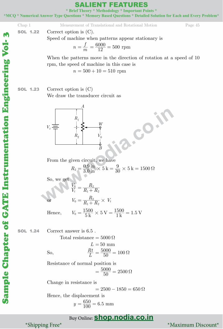
Chap 1 Measurement of Translational and Rotational Motion Page 45
Buy Online: shop.nodia.co.in *Shipping Free* *Maximum Discount*
SAlIENT FEATURES* Brief Theory * Methodology * Important Points *
*MCQ * Numerical Answer Type Questions * Memory Based Questions * Detailed Solution for Each and Every Problem*
Sam
ple
Ch
apte
r o
f G
AT
E I
nst
rum
enta
tio
n E
ngin
eeri
ng V
ol-
3
Sam
ple C
hap
ter of G
AT
E In
strum
entatio
n E
ngin
eering V
ol- 3
www.nodia.co.in
SOl 1.22 Correct option is (C).Speed of machine when patterns appear stationary is
n mf= 12
6000 500= = rpm
When the patterns move in the direction of rotation at a speed of 10 rpm, the speed of machine in this case is n 500 10 510= + = rpm
SOl 1.23 Correct option is (C)We draw the transducer circuit as
From the given circuit, we have
R2 ..inin k k3 0
0 9 5 309 5 1500# # Ω = = =
So, we get
VVt
0 R RR1 2
2= +
or V0 R RR Vt1 2
2 #= +
Hence, V0 .k V k V51500 5 1
1500 1 5#= = =
SOl 1.24 Correct answer is 6.5 . Total resistance 5000Ω = L 50= mm
So, LRt 50
5000 100Ω = =
Resistance of normal position is
505000 2500Ω = =
Change in resistance is 2500 1850 650Ω = − =Hence, the displacement is
y .100650 6 5= = mm
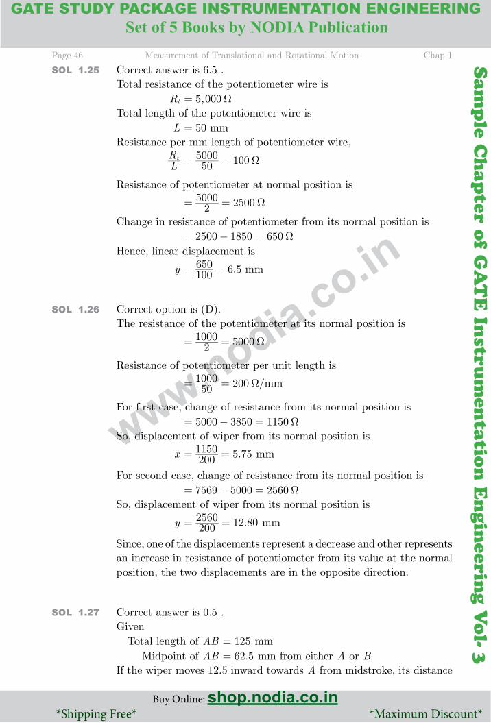
Page 46 Measurement of Translational and Rotational Motion Chap 1
Buy Online: shop.nodia.co.in *Shipping Free* *Maximum Discount*
GATE STUDY PACKAGE INSTRUMENTATION ENGINEERING
Buy Online: shop.nodia.co.in *Shipping Free* *Maximum Discount*
SAlIENT FEATURES* Brief Theory * Methodology * Important Points *
*MCQ * Numerical Answer Type Questions * Memory Based Questions * Detailed Solution for Each and Every Problem*Set of 5 Books by NODIA Publication
Sam
ple
Ch
apte
r o
f G
AT
E I
nst
rum
enta
tio
n E
ngin
eeri
ng V
ol-
3
Sam
ple C
hap
ter of G
AT
E In
strum
entatio
n E
ngin
eering V
ol- 3
www.nodia.co.in
SOl 1.25 Correct answer is 6.5 .Total resistance of the potentiometer wire is Rt ,5 000Ω =Total length of the potentiometer wire is L 50= mmResistance per mm length of potentiometer wire,
LRt 50
5000 100Ω = =
Resistance of potentiometer at normal position is
25000 2500Ω = =
Change in resistance of potentiometer from its normal position is 2500 1850 650Ω = − =Hence, linear displacement is
y .100650 6 5= = mm
SOl 1.26 Correct option is (D).The resistance of the potentiometer at its normal position is
21000 5000Ω = =
Resistance of potentiometer per unit length is
/mm501000 200Ω = =
For first case, change of resistance from its normal position is 5000 3850 1150Ω = − =So, displacement of wiper from its normal position is
x .2001150 5 75= = mm
For second case, change of resistance from its normal position is 7569 5000 2560Ω = − =So, displacement of wiper from its normal position is
y .2002560 12 80= = mm
Since, one of the displacements represent a decrease and other represents an increase in resistance of potentiometer from its value at the normal position, the two displacements are in the opposite direction.
SOl 1.27 Correct answer is 0.5 .Given Total length of AB 125= mm Midpoint of AB .62 5= mm from either A or BIf the wiper moves 12.5 inward towards A from midstroke, its distance
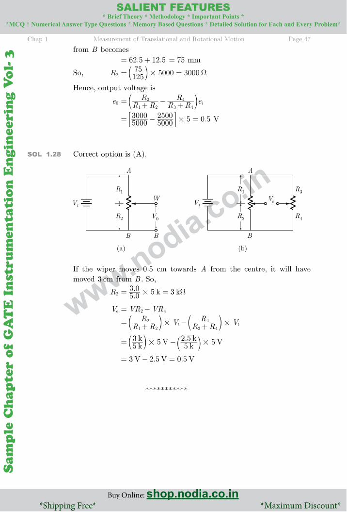
Chap 1 Measurement of Translational and Rotational Motion Page 47
Buy Online: shop.nodia.co.in *Shipping Free* *Maximum Discount*
SAlIENT FEATURES* Brief Theory * Methodology * Important Points *
*MCQ * Numerical Answer Type Questions * Memory Based Questions * Detailed Solution for Each and Every Problem*
Sam
ple
Ch
apte
r o
f G
AT
E I
nst
rum
enta
tio
n E
ngin
eeri
ng V
ol-
3
Sam
ple C
hap
ter of G
AT
E In
strum
entatio
n E
ngin
eering V
ol- 3
www.nodia.co.in
from B becomes . .62 5 12 5= + 75= mm
So, R2 12575 5000 3000# Ω = =b l
Hence, output voltage is
e0 R RR
R RR ei
1 2
2
3 4
4= + − +c m
.50003000
50002500 5 0 5#= − =; E V
SOl 1.28 Correct option is (A).
If the wiper moves 0.5 cm towards A from the centre, it will have moved cm3 from B . So,
R2 .. k k5 03 0 5 3# Ω = =
Ve VR VR2 4= −
R RR V R R
R Vt t1 2
2
3 4
4# #= + − +c cm m
.kk V k
k V53 5 5
2 5 5# #= −b bl l
. .V V V3 2 5 0 5= − =


![pH - Hanna Instruments · What is pH? 0 2 4 6 8 10 12 14 1e-14 1e-13 1e-12 1e-11 1e-10 1e-09 1e-08 1e-07 1e-06 1e-05 1e-04 0.001 0.01 0.1 1. pH Hydrogen Ion Concentration [H+] Pure](https://img.dokumen.tips/doc/110x75/5fffb191970a7d07ff50bec3/ph-hanna-instruments-what-is-ph-0-2-4-6-8-10-12-14-1e-14-1e-13-1e-12-1e-11-1e-10.jpg)