Embed Size (px)
Citation preview
Mt. San Antonio Col lege - Student Support Services Schematic Design
Student Support Services Mt. San Antonio College
November 16, 2012
SCHEMATIC DESIGN REPORT

Mt. San Antonio Col lege - Student Support Services Schematic Design
Mt. San Antonio Col lege - Student Support Services Schematic Design i
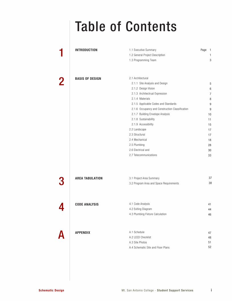
Table of Contents1.1 Executive Summary
1.2 General Project Description
1.3 Programming Team
2.1 Architectural
2.1.1 Site Analysis and Design
2.1.2 Design Vision
2.1.3 Architectrual Expression
2.1.4 Materials
2.1.5 Applicable Codes and Standards
2.1.6 Occupancy and Construction Classification
2.1.7 Building Envelope Analysis
2.1.8 Sustainability
2.1.9 Accessibility
2.2 Landscape
2.3 Structural
2.4 Mechanical
2.5 Plumbing
2.6 Electrical and
2.7 Telecommunications
3.1 Project Area Summary
3.2 Program Area and Space Requirements
4.1 Code Analysis
4.2 Exiting Diagram
4.3 Plumbing Fixture Calculation
A.1 Schedule
A.2 LEED Checklist
A.3 Site Photos
A.4 Schematic Site and Floor Plans
1
2
3
4
A
INTRODUCTION
BASIS OF DESIGN
CODE ANALYSIS
AREA TABULATION
APPENDIX
Page 1
1
3
5
6
7
8
9
9
10
11
15
17
17
18
28
30
33
37
38
41
44
46
47
48
51
52
i i Mt. San Antonio Col lege - Student Support Services Schematic Design
Mt. San Antonio Col lege - Student Support ServicesSchematic Design 1
IntroductionEXECUTIVE SUMMARYGENERAL PROJECT DESCRIPTIONSCHEMATIC DESIGN TEAM
1
1.1 EXECUTIVE SUMMARY
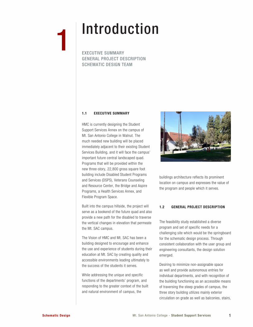
HMC is currently designing the Student
Support Services Annex on the campus of
Mt. San Antonio College in Walnut. The
much needed new building will be placed
immediately adjacent to their existing Student
Services Building, and it will face the campus’
important future central landscaped quad.
Programs that will be provided within the
new three-story, 22,800 gross square foot
building include Disabled Student Programs
and Services (DSPS), Veterans Counseling
and Resource Center, the Bridge and Aspire
Programs, a Health Services Annex, and
Flexible Program Space.
Built into the campus hillside, the project will
serve as a bookend of the future quad and also
provide a new path for the disabled to traverse
the vertical changes in elevation that permeate
the Mt. SAC campus.
The Vision of HMC and Mt. SAC has been a
building designed to encourage and enhance
the use and experience of students during their
education at Mt. SAC by creating quality and
accessible environments leading ultimately to
the success of the students it serves.
While addressing the unique and specific
functions of the departments’ program, and
responding to the greater context of the built
and natural environment of campus, the
buildings architecture reflects its prominent
location on campus and expresses the value of
the program and people which it serves.
1.2 GENERAL PROJECT DESCRIPTION
The feasibility study established a diverse
program and set of specific needs for a
challenging site which would be the springboard
for the schematic design process. Through
consistent collaboration with the user group and
engineering consultants, the design solution
emerged.
Desiring to minimize non-assignable space
as well and provide autonomous entries for
individual departments, and with recognition of
the building functioning as an accessible means
of traversing the steep grades of campus, the
three story building utilizes mainly exterior
circulation on grade as well as balconies, stairs,
2 Mt. San Antonio Col lege - Student Support Services Schematic Design
and elevators. DSPS and Veterans Services are
on the lower level, and though below grade on
the majority of the north and east sides, they
are still provided with convenient access to the
adjacent student services building and access
to the outdoor plaza and patio space. Student
Health along with Bridge and Aspire Programs
are on the second level, entering from the
northeast on grade through the buildings
breezeway. This allows for the most convenient
emergency access from the east for the Student
Health Program, as well as allowing for on
grade outdoor patio space for the Bridge and
Aspire Program to the North. The third level will
contain Flexible Program Space on the south
overlooking the large future campus green
space. It will also contain screened mechanical
spaces to eliminate rooftop air handling units.
The project utilizes a variety of suitably scaled-
outdoor spaces as an extension of the learning
and social environments.
The project will pursue LEED Silver as a
minimum. The college would like to exemplify
accessibility and equal access.
PROGRAM SUMMARY (SEE 3.1 FOR COMPLETE LIST)
- 17,240 Assignable Square Feet
- (5) Departments
- (3) Classrooms & Computer Lab
- (4) Study Centers & Open Resourse,
Peer Mentoring
- (2) Media/ Tech Support Spaces
- (3) Group Study Rooms
- (3) Health Treatment Rooms with Support
Spaces
- (23) Faculty and Counselor Offices with
Support Spaces
3Mt. San Antonio Col lege - Student Support ServicesSchematic Design
1.3 SCHEMATIC DESIGN TEAM
Mt. San Antonio College
Anabel Perez, Coordinator, Bridge Program
Audrey Yamagata-Noji , Vice President, Student Services
Bill Eastham, Director, Technical Services
Chau Dao, Director, Financial Aid/ Veterans Services
Gary Nellesen, Director, Facilities Planing and Managment
Grace T. Hanson, Director, Disabled Students Programs & Services
Sandra Samples, Director, Student Health Services
Thomas Mauch, Dean, Counseling
HMC ArchitectsKen Salyer, AIA, Principal in Charge
Sheryl Sterry, AIA Senior Education Facilities Planner
Jason Cochran, AIA, Project Manager
Simon Solis, Project Designer
Jessica Liu, Senior Interior Designer
Susan Chiang, AIA, Interior Project Designer
P2S Engineering Inc. – Mechanical, Electrical and Plumbing EngineeringPrabu Shankar, Electrical Engineer, Project Manager
James Del Monico, Mechanical Engineer
Eric Gomez, Plumbing Designer
R.M. Byrd and Associats. – Structural EngineeringRick Byrd, Structural Engineer, President
Psomas – Civil EngineeringJeff T. Chess, PE Alysen Weiland, PE
EPT Design - LandscapeStephen Carroll, ASLA - Principal
Matt Lysne, Landscaper Designer
Acknowledgements
4 Mt. San Antonio Col lege - Student Support Services Schematic Design
Mt. San Antonio Col lege - Student Support ServicesSchematic Design 5
Basis of DesignARCHITECTURAL SITE ANALYSIS & DESIGN DESIGN VISION ARCHITECTURAL EXPRESSION BUILDING ENVELOPE SUSTAINABILITY ACCESSIBILITY CIVILLANDSCAPESTRUCTURALMECHANICALPLUMBINGELECTRICAL & TELECOMMUNICATIONS
2
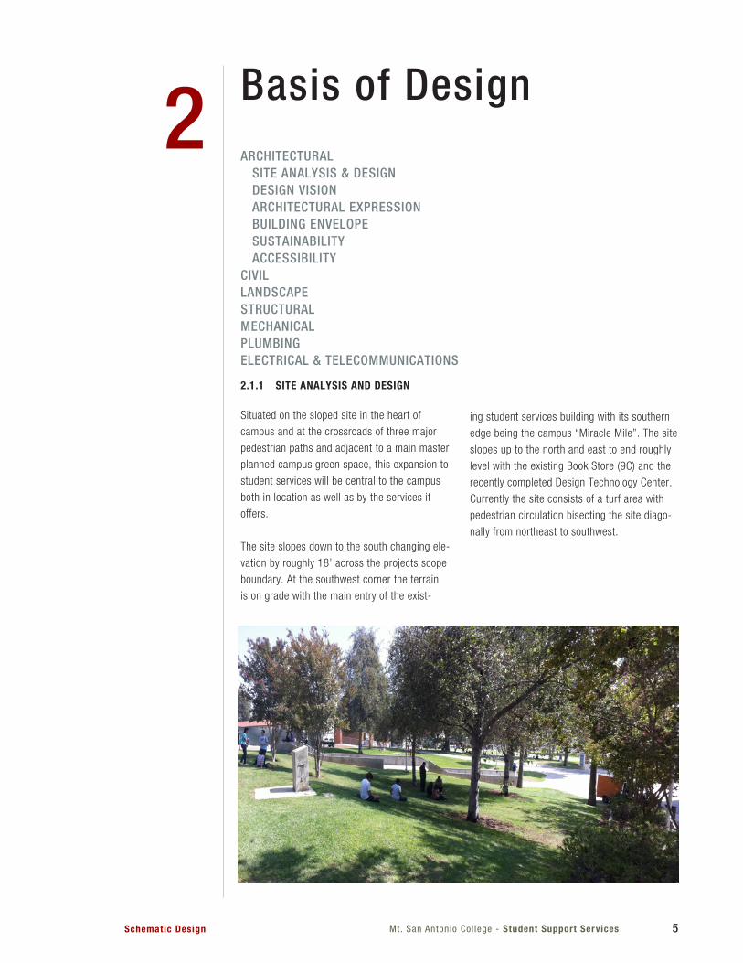
2.1.1 SITE ANALYSIS AND DESIGN
Situated on the sloped site in the heart of
campus and at the crossroads of three major
pedestrian paths and adjacent to a main master
planned campus green space, this expansion to
student services will be central to the campus
both in location as well as by the services it
offers.
The site slopes down to the south changing ele-
vation by roughly 18’ across the projects scope
boundary. At the southwest corner the terrain
is on grade with the main entry of the exist-
ing student services building with its southern
edge being the campus “Miracle Mile”. The site
slopes up to the north and east to end roughly
level with the existing Book Store (9C) and the
recently completed Design Technology Center.
Currently the site consists of a turf area with
pedestrian circulation bisecting the site diago-
nally from northeast to southwest.
6 Mt. San Antonio Col lege - Student Support Services Schematic Design
2.1.2 DESIGN VISION
The Vision of HMC and Mt. SAC has been a
building designed to encourage and enhance
the use and experience of students during their
education at Mt. SAC by creating quality and
accessible environments leading ultimately to
the success of the students it serves.
While addressing the unique and specific
functions of the departments’ program, and
responding to the greater context of the built
and natural environment of campus, the
building’s architecture reflects its prominent
location on campus and expresses the value of
the program and people which it serves.
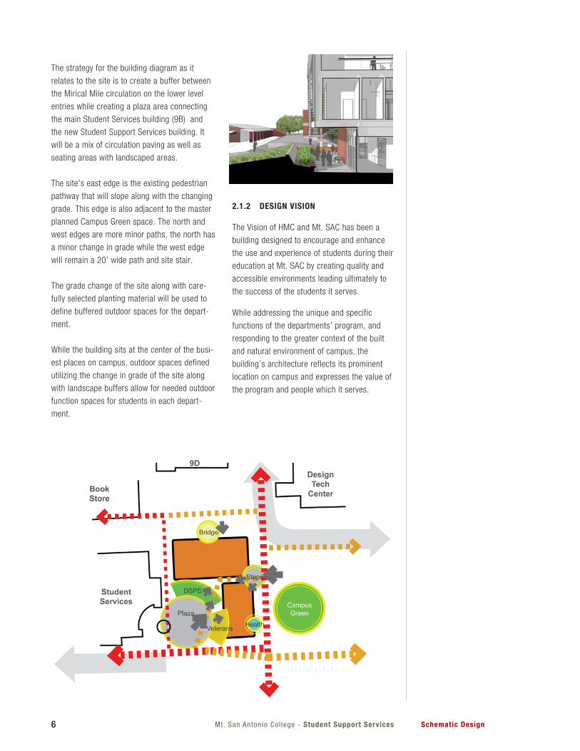
The strategy for the building diagram as it
relates to the site is to create a buffer between
the Mirical Mile circulation on the lower level
entries while creating a plaza area connecting
the main Student Services building (9B) and
the new Student Support Services building. It
will be a mix of circulation paving as well as
seating areas with landscaped areas.
The site’s east edge is the existing pedestrian
pathway that will slope along with the changing
grade. This edge is also adjacent to the master
planned Campus Green space. The north and
west edges are more minor paths, the north has
a minor change in grade while the west edge
will remain a 20’ wide path and site stair.
The grade change of the site along with care-
fully selected planting material will be used to
define buffered outdoor spaces for the depart-
ment.
While the building sits at the center of the busi-
est places on campus, outdoor spaces defined
utilizing the change in grade of the site along
with landscape buffers allow for needed outdoor
function spaces for students in each depart-
ment.
7Mt. San Antonio Col lege - Student Support ServicesSchematic Design
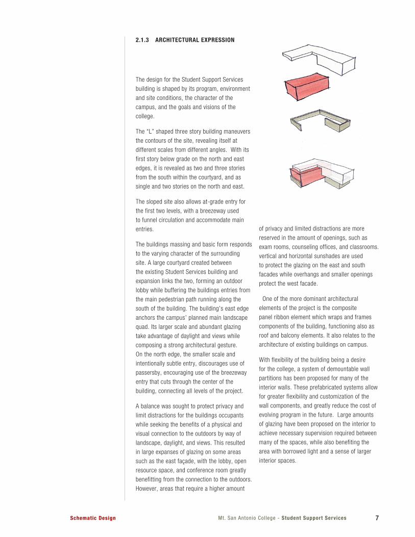
2.1.3 ARCHITECTURAL EXPRESSION
The design for the Student Support Services
building is shaped by its program, environment
and site conditions, the character of the
campus, and the goals and visions of the
college.
The “L” shaped three story building maneuvers
the contours of the site, revealing itself at
different scales from different angles. With its
first story below grade on the north and east
edges, it is revealed as two and three stories
from the south within the courtyard, and as
single and two stories on the north and east.
The sloped site also allows at-grade entry for
the first two levels, with a breezeway used
to funnel circulation and accommodate main
entries.
The buildings massing and basic form responds
to the varying character of the surrounding
site. A large courtyard created between
the existing Student Services building and
expansion links the two, forming an outdoor
lobby while buffering the buildings entries from
the main pedestrian path running along the
south of the building. The building’s east edge
anchors the campus’ planned main landscape
quad. Its larger scale and abundant glazing
take advantage of daylight and views while
composing a strong architectural gesture.
On the north edge, the smaller scale and
intentionally subtle entry, discourages use of
passersby, encouraging use of the breezeway
entry that cuts through the center of the
building, connecting all levels of the project.
A balance was sought to protect privacy and
limit distractions for the buildings occupants
while seeking the benefits of a physical and
visual connection to the outdoors by way of
landscape, daylight, and views. This resulted
in large expanses of glazing on some areas
such as the east façade, with the lobby, open
resource space, and conference room greatly
benefitting from the connection to the outdoors.
However, areas that require a higher amount
of privacy and limited distractions are more
reserved in the amount of openings, such as
exam rooms, counseling offices, and classrooms.
vertical and horizontal sunshades are used
to protect the glazing on the east and south
facades while overhangs and smaller openings
protect the west facade.
One of the more dominant architectural
elements of the project is the composite
panel ribbon element which wraps and frames
components of the building, functioning also as
roof and balcony elements. It also relates to the
architecture of existing buildings on campus.
With flexibility of the building being a desire
for the college, a system of demountable wall
partitions has been proposed for many of the
interior walls. These prefabricated systems allow
for greater flexibility and customization of the
wall components, and greatly reduce the cost of
evolving program in the future. Large amounts
of glazing have been proposed on the interior to
achieve necessary supervision required between
many of the spaces, while also benefiting the
area with borrowed light and a sense of larger
interior spaces.
8 Mt. San Antonio Col lege - Student Support Services Schematic Design
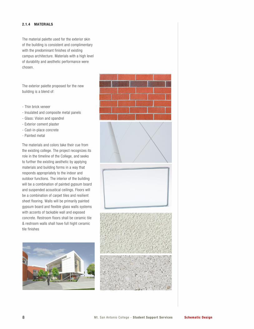
2.1.4 MATERIALS
The material palette used for the exterior skin
of the building is consistent and complimentary
with the predominant finishes of existing
campus architecture. Materials with a high level
of durability and aesthetic performance were
chosen.
The exterior palette proposed for the new
building is a blend of:
- Thin brick veneer
- Insulated and composite metal panels
- Glass: Vision and spandrel
- Exterior cement plaster
- Cast-in-place concrete
- Painted metal
The materials and colors take their cue from
the existing college. The project recognizes its
role in the timeline of the College, and seeks
to further the existing aesthetic by applying
materials and building forms in a way that
responds appropriately to the indoor and
outdoor functions. The interior of the building
will be a combination of painted gypsum board
and suspended acoustical ceilings. Floors will
be a combination of carpet tiles and resilient
sheet flooring. Walls will be primarily painted
gypsum board and flexible glass walls systems
with accents of tackable wall and exposed
concrete. Restroom floors shall be ceramic tile
& restroom walls shall have full hight ceramic
tile finishes
9Mt. San Antonio Col lege - Student Support ServicesSchematic Design
2.1.5 APPLICABLE CODES AND STANDARS
List of 2010 California Code of Regulations
(C.C.R.):
Part 1 2010 California Building Standards
Administrative Code, Title 24 C.C.R.
Part 2 2010 California Building Code,
Title 24 C.C.R.
Part 3 2010 California Electrical Code,
Title 24 C.C.R.
Part 4 2010 California Mechanical Code,
Title 24 C.C.R.
Part 5 2010 California Plumbing Code,
Title 24 C.C.R.
Part 6 2010 California Energy Code,
Title 24 C.C.R.
Part 9 2010 California Fire Code,
Title 24 C.C.R.
Part 11 2010 California Green Building
Standards Code (CALGreen Code),
Title 24 C.C.R.
Part 12 2010 California Referenced
Standards Code, Title 24 C.C.R.
2.1.6 OCCUPANCY AND CONSTRUCTION
CLASSIFICATIONS
The building is comprised of mixed occupancies
B and A. For the purposes of the code analysis
the building will be classified as a Type A
Non-Separated Occupancy, per CBC Chapter
5, Section 508.3. The Type of construction is
Type II-B with an approved fully automatic fire
sprinkler system. Refer to section 4.1 for the
complete analysis.
10 Mt. San Antonio Col lege - Student Support Services Schematic Design
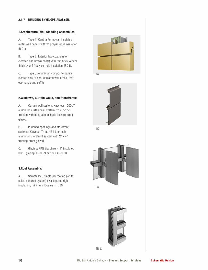
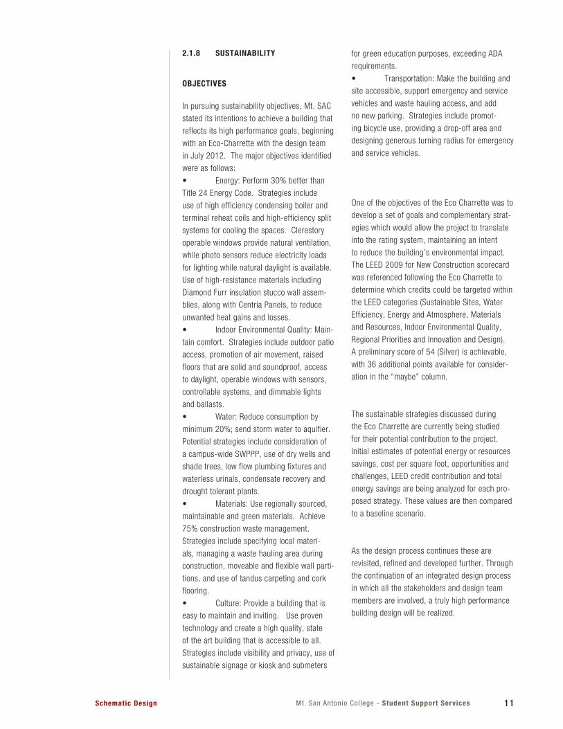
2.1.7 BUILDING ENVELOPE ANALYSIS
1.Architectural Wall Cladding Assemblies:
A. Type 1: Centria Formawall insulated
metal wall panels with 3” polyiso rigid insulation
(R 21).
B. Type 2: Exterior two coat plaster
(scratch and brown coats) with thin brick veneer
finish over 3” polyiso rigid insulation (R 21).
C. Type 3: Aluminum composite panels,
located only at non-insulated wall areas, roof
overhangs and soffits.
2.Windows, Curtain Walls, and Storefronts:
A. Curtain wall system: Kawneer 1600UT
aluminum curtain wall system, 2” x 7-1/2”
framing with integral sunshade louvers, front
glazed.
B. Punched openings and storefront
systems: Kawneer Trifab 451 (thermal)
aluminum storefront system with 2” x 4”
framing, front glazed.
C. Glazing: PPG Starphire - 1” insulated
low-E glazing, U=0.29 and SHGC=0.28
3.Roof Assembly:
A. Sarnafil PVC single-ply roofing (white
color, adhered system) over tapered rigid
insulation, minimum R-value = R 30.
1A
1C
2A
2B-C
11Mt. San Antonio Col lege - Student Support ServicesSchematic Design
2.1.8 SUSTAINABILITY
OBJECTIVES
In pursuing sustainability objectives, Mt. SAC
stated its intentions to achieve a building that
reflects its high performance goals, beginning
with an Eco-Charrette with the design team
in July 2012. The major objectives identified
were as follows:
• Energy:Perform30%betterthan
Title 24 Energy Code. Strategies include
use of high efficiency condensing boiler and
terminal reheat coils and high-efficiency split
systems for cooling the spaces. Clerestory
operable windows provide natural ventilation,
while photo sensors reduce electricity loads
for lighting while natural daylight is available.
Use of high-resistance materials including
Diamond Furr insulation stucco wall assem-
blies, along with Centria Panels, to reduce
unwanted heat gains and losses.
• IndoorEnvironmentalQuality:Main-
tain comfort. Strategies include outdoor patio
access, promotion of air movement, raised
floors that are solid and soundproof, access
to daylight, operable windows with sensors,
controllable systems, and dimmable lights
and ballasts.
• Water:Reduceconsumptionby
minimum20%;sendstormwatertoaquifier.
Potential strategies include consideration of
a campus-wide SWPPP, use of dry wells and
shade trees, low flow plumbing fixtures and
waterless urinals, condensate recovery and
drought tolerant plants.
• Materials:Useregionallysourced,
maintainable and green materials. Achieve
75%constructionwastemanagement.
Strategies include specifying local materi-
als, managing a waste hauling area during
construction, moveable and flexible wall parti-
tions, and use of tandus carpeting and cork
flooring.
• Culture:Provideabuildingthatis
easy to maintain and inviting. Use proven
technology and create a high quality, state
of the art building that is accessible to all.
Strategies include visibility and privacy, use of
sustainable signage or kiosk and submeters
for green education purposes, exceeding ADA
requirements.
• Transportation:Makethebuildingand
site accessible, support emergency and service
vehicles and waste hauling access, and add
no new parking. Strategies include promot-
ing bicycle use, providing a drop-off area and
designing generous turning radius for emergency
and service vehicles.
One of the objectives of the Eco Charrette was to
develop a set of goals and complementary strat-
egies which would allow the project to translate
into the rating system, maintaining an intent
to reduce the building’s environmental impact.
The LEED 2009 for New Construction scorecard
was referenced following the Eco Charrette to
determine which credits could be targeted within
the LEED categories (Sustainable Sites, Water
Efficiency, Energy and Atmosphere, Materials
andResources,IndoorEnvironmentalQuality,
Regional Priorities and Innovation and Design).
A preliminary score of 54 (Silver) is achievable,
with 36 additional points available for consider-
ation in the “maybe” column.
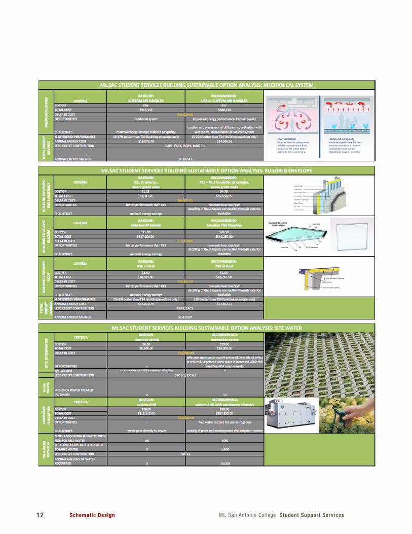
The sustainable strategies discussed during
the Eco Charrette are currently being studied
for their potential contribution to the project.
Initial estimates of potential energy or resources
savings, cost per square foot, opportunities and
challenges, LEED credit contribution and total
energy savings are being analyzed for each pro-
posed strategy. These values are then compared
to a baseline scenario.
As the design process continues these are
revisited, refined and developed further. Through
the continuation of an integrated design process
in which all the stakeholders and design team
members are involved, a truly high performance
building design will be realized.
12 Mt. San Antonio Col lege Student Support ServicesSchematic Design
13Mt. San Antonio Col lege - Student Support ServicesSchematic Design
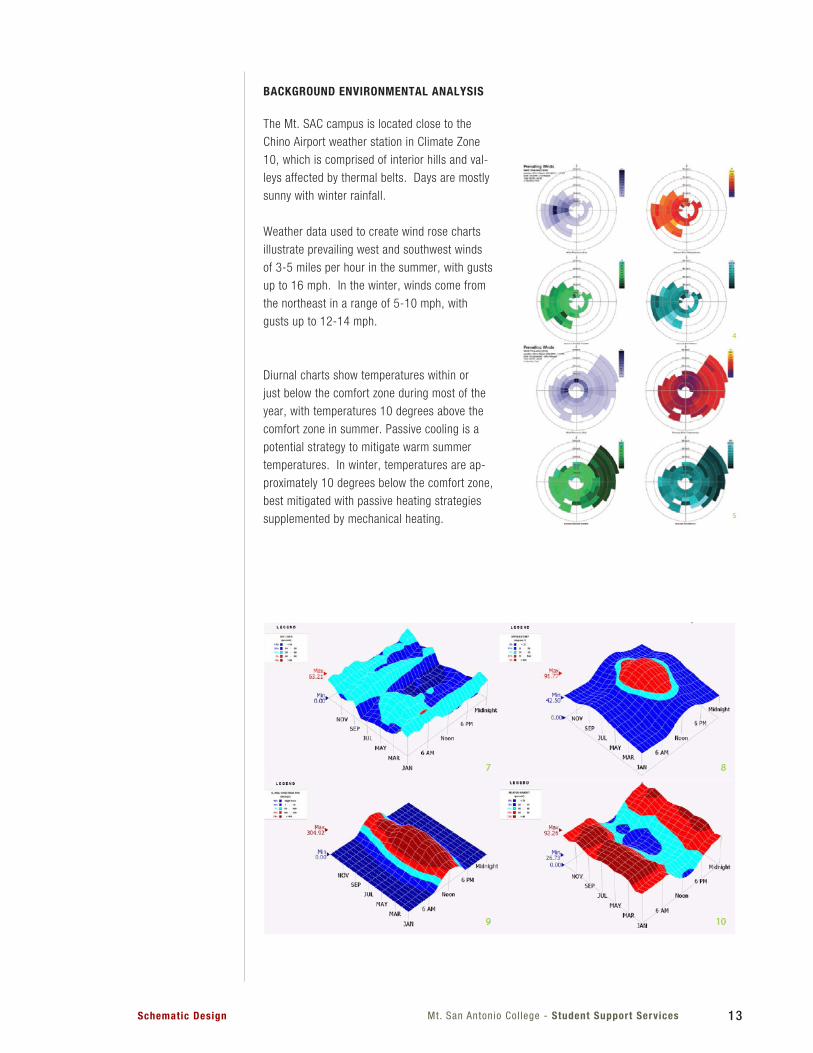
BACKGROUND ENVIRONMENTAL ANALYSIS
The Mt. SAC campus is located close to the
Chino Airport weather station in Climate Zone
10, which is comprised of interior hills and val-
leys affected by thermal belts. Days are mostly
sunny with winter rainfall.
Weather data used to create wind rose charts
illustrate prevailing west and southwest winds
of 3-5 miles per hour in the summer, with gusts
up to 16 mph. In the winter, winds come from
the northeast in a range of 5-10 mph, with
gusts up to 12-14 mph.
Diurnal charts show temperatures within or
just below the comfort zone during most of the
year, with temperatures 10 degrees above the
comfort zone in summer. Passive cooling is a
potential strategy to mitigate warm summer
temperatures. In winter, temperatures are ap-
proximately 10 degrees below the comfort zone,
best mitigated with passive heating strategies
supplemented by mechanical heating.
14 Mt. San Antonio Col lege Student Support ServicesSchematic Design
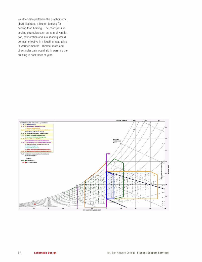
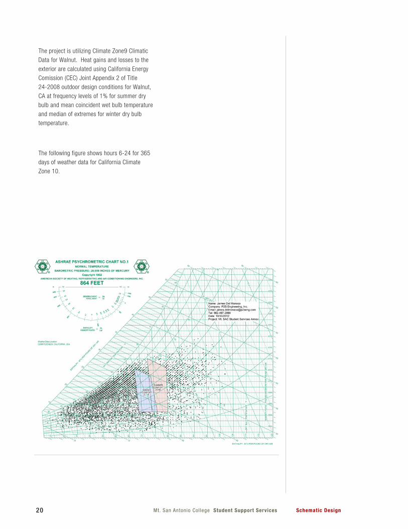
Weather data plotted in the psychometric
chart illustrates a higher demand for
cooling than heating. The chart passive
cooling strategies such as natural ventila-
tion, evaporation and sun shading would
be most effective in mitigating heat gains
in warmer months. Thermal mass and
direct solar gain would aid in warming the
building in cool times of year.
15Mt. San Antonio Col lege - Student Support ServicesSchematic Design
2.1.9 ACCESSIBILITY
The issue of accessibility compliance for
facilities is a vital issue in the State of California.
The Division of State Architect (DSA) has taken
the lead on assuring that buildings constructed
under their purveiw are designed to comply with
the strict standards of the California Building
Code and the Federal American with Disabilities
Act (ADA). The College has been dedicated to
providing access to all members of the campus
community and will provide the necessary
amenities to this facility. The expressed vision
of Mt. SAC and the goal of HMC is to deliver a
building that goes beyond the minimum required
by code. The major factors to be considered
are:
Access to buildings from within College
Path of Travel to Accessible Parking
Vertical Circulation
Tactile Signage
Vicinity to Accessible Restrooms
Accessibility within the Building
ACCESSIBLE DESIGN ELEMENTS
Besides meeting the basic intent of the code,
the design will seek to always provide equivalent
facilitation.
Access to Building. The college is located on a
hill, making relatively flat continuous surfaces
difficult. The project will connect to accessible
paths of travel on both the north and south
sides, and provide vertical circulation through
exterior accessible elevators.
Path of Travel to Accessible Parking
The existing accessible parking is to the east
of the project, in lot G. The project will connect
to an accessible path currently ending near the
northeast corner of the project site.
Vertical Circulation
The elevator is located on the exterior near the
center corner of the building, accessible through
the buildings breezway on upper levels and at
the plaza on the lower level. Positioning the
elevator on the exterior allows 24-hour use if
the campus should choose to operate it as such.
Tactile Signage
Directional signage will seamlessly integrate
tactile wayfinding devices. This signage will
identify all rooms to avoid confusion for the
building occupants.
Vicinity to Restrooms
Student restrooms are located on the lower
and upper level with additional staff restrooms
on the second level, providing convenient
access for the building users.
16 Mt. San Antonio Col lege - Student Support Services Schematic Design
17Mt San Antonio Col lege Student Support ServicesSchematic Design
2.2 LANDSCAPE
The site on which Mt. San Antonio College
currently sits was once part of Rancho La
Puente - The Bridge Ranch - a 49,000 acre
ranch that helped set the agrarian theme that
still permeates the region. Parts of this land
were used for raising cattle and growing wheat,
grapes, and fruit trees. This is still evident
today, particularly by way of the outstanding
agricultural programs present at both Mt. Sac
and neighboring Cal Poly Pomona. To merge
this unique history with the native ecological
character of the site will provide a compelling
landscape that will complement the existing
campus landscape pallet and serve as an asset
to the Mt. San Antonio College campus.
The Gateways
The main entrances to the building will be
accentuated by linear paving reminiscent of
crop rows found in agricultural fields.
The Grasslands
To reflect both the native ecology of the city
of Walnut as well as the agricultural history,
plantings in these areas will be composed of
native grasses whose aesthetic quality is similar
to the wheat grass fields that permeated the
region.
The Bridges
To celebrate the academic services put forth by
the college and to pay tribute to the historical
precedent of the “La Puente Ranch”, the idea
of bridges will be reflected in the use of porous
accented paving.
Courtyard Spaces
These outdoor rooms will be defined by linear
paving patterns on the ground plane, native
tree species (i.e. Sycamores and Oaks) to serve
as the canopy, and ample seating with power
outlets, encouraging students to enhabit the
space providing maximum function and comfort.
The linearity found in many agricultural
fields is a powerful organizational design
language and one that will establish a salient
aesthetic connection between the site and
the surrounding environment. Applying this
language to paving patterns, seating, and other
infrastructure will help emphasize this, while
complimenting it with softscape will make
it both visually striking and environmentally
sensitive.
Oak and Sycamores, two native trees with
distinct forms and generous canopies, will
provide shade and compliment the linear forms
and native grasses. The forms of the planting
will be gleaned from patterns found in the
surrounding agricultural fields. The predominant
planting will be grasses, which marry native
ecology with the prevailing agricultural types of
the area.
2.3 STRUCTURAL
The structural system for the proposed subject
project is to have a gravity load bearing system
comprised of a structural concrete slab at the
second floor with concrete beams, walls and
columns. The third floor and roof are to be
constructed with concrete over metal deck steel
beam and column framing. The lateral force
resisting system is to be comprised of concrete
shear walls at all floor levels.
This system was chosen based on the
moderate slope of the proposed building site
and incorporating the design requirement
of having access to both the first floor and
the second floor at grade. This requirement
provides the opportunity to use a concrete
wall element that will both retain the earth at
the first floor level and provide both vertical
and lateral load bearing elements. With the
architectural arrangement of the structure the
use of concrete shear walls throughout allows
for some flexibility in the locations of openings.
Concrete walls in combination with the rigid
floor and roof systems provide efficient lateral
load transfer from the horizontal diaphragms to
the vertical lateral force resisting elements as
well as economical connections of structural
elements.
18 Mt. San Antonio Col lege Student Support Services Schematic Design
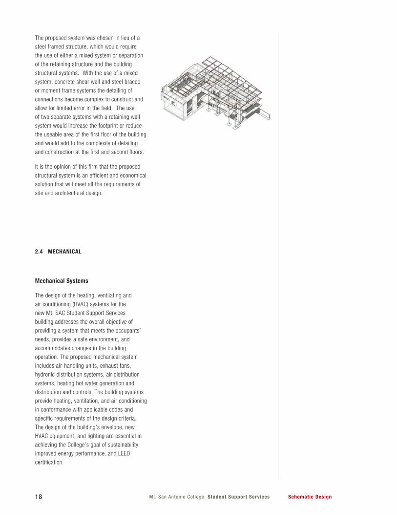
The proposed system was chosen in lieu of a
steel framed structure, which would require
the use of either a mixed system or separation
of the retaining structure and the building
structural systems. With the use of a mixed
system, concrete shear wall and steel braced
or moment frame systems the detailing of
connections become complex to construct and
allow for limited error in the field. The use
of two separate systems with a retaining wall
system would increase the footprint or reduce
the useable area of the first floor of the building
and would add to the complexity of detailing
and construction at the first and second floors.
It is the opinion of this firm that the proposed
structural system is an efficient and economical
solution that will meet all the requirements of
site and architectural design.
2.4 MECHANICAL
Mechanical Systems
The design of the heating, ventilating and
air conditioning (HVAC) systems for the
new Mt. SAC Student Support Services
building addresses the overall objective of
providing a system that meets the occupants’
needs, provides a safe environment, and
accommodates changes in the building
operation. The proposed mechanical system
includes air-handling units, exhaust fans,
hydronic distribution systems, air distribution
systems, heating hot water generation and
distribution and controls. The building systems
provide heating, ventilation, and air conditioning
in conformance with applicable codes and
specific requirements of the design criteria.
The design of the building’s envelope, new
HVAC equipment, and lighting are essential in
achieving the College’s goal of sustainability,
improved energy performance, and LEED
certification.
19Mt San Antonio Col lege Student Support ServicesSchematic Design
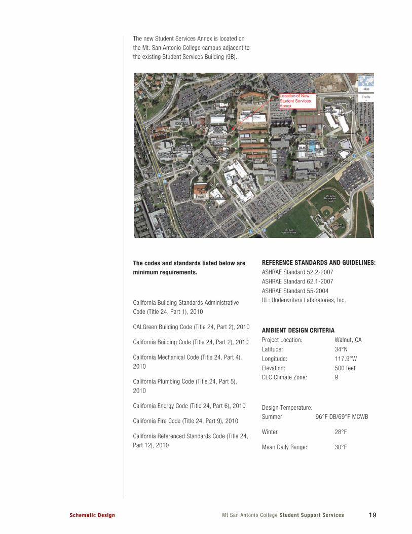
The new Student Services Annex is located on
the Mt. San Antonio College campus adjacent to
the existing Student Services Building (9B).
The codes and standards listed below are minimum requirements.
California Building Standards Administrative
Code (Title 24, Part 1), 2010
CALGreen Building Code (Title 24, Part 2), 2010
California Building Code (Title 24, Part 2), 2010
California Mechanical Code (Title 24, Part 4),
2010
California Plumbing Code (Title 24, Part 5),
2010
California Energy Code (Title 24, Part 6), 2010
California Fire Code (Title 24, Part 9), 2010
California Referenced Standards Code (Title 24,
Part 12), 2010
REFERENCE STANDARDS AND GUIDELINES:ASHRAE Standard 52.2-2007
ASHRAE Standard 62.1-2007
ASHRAE Standard 55-2004
UL: Underwriters Laboratories, Inc.
AMBIENT DESIGN CRITERIAProject Location: Walnut, CA
Latitude: 34°N
Longitude: 117.9°W
Elevation: 500 feet
CEC Climate Zone: 9
Design Temperature:
Summer 96°F DB/69°F MCWB
Winter 28°F
Mean Daily Range: 30°F
20 Mt. San Antonio Col lege Student Support Services Schematic Design
The project is utilizing Climate Zone9 Climatic
Data for Walnut. Heat gains and losses to the
exterior are calculated using California Energy
Comission (CEC) Joint Appendix 2 of Title
24-2008 outdoor design conditions for Walnut,
CA at frequency levels of 1% for summer dry
bulb and mean coincident wet bulb temperature
and median of extremes for winter dry bulb
temperature.
The following figure shows hours 6-24 for 365
days of weather data for California Climate
Zone 10.
21Mt San Antonio Col lege Student Support ServicesSchematic Design
HVAC PERFORMANCE CRITERIA
The HVAC systems have been designed to
provide user comfort and enhanced indoor
environmental quality while maximizing energy
efficiency. Relative humidity between 30%
and 80% is considered normal for the air
conditioning system. Unless otherwise noted,
the spaces in this building do not require
specialized humidity control equipment.
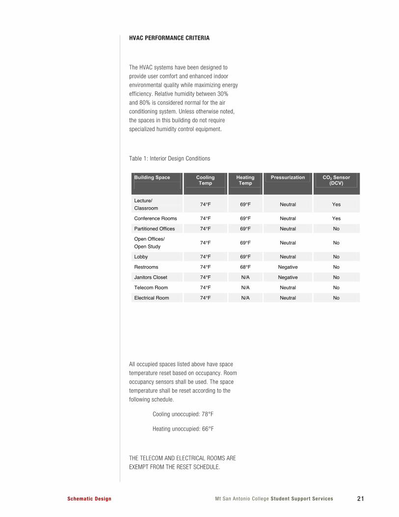
Table 1: Interior Design Conditions
All occupied spaces listed above have space
temperature reset based on occupancy. Room
occupancy sensors shall be used. The space
temperature shall be reset according to the
following schedule.
Cooling unoccupied: 78°F
Heating unoccupied: 66°F
THE TELECOM AND ELECTRICAL ROOMS ARE
EXEMPT FROM THE RESET SCHEDULE.
Building Space
Cooling Temp
Heating Temp
Pressurization CO2 Sensor (DCV)
Lecture/
Classroom74°F 69°F Neutral Yes
ConferenceRooms 74°F 69°F Neutral Yes
PartitionedOffices 74°F 69°F Neutral No
OpenOffices/
OpenStudy74°F 69°F Neutral No
Lobby 74°F 69°F Neutral No
Restrooms 74°F 68°F Negative No
JanitorsCloset 74°F N/A Negative No
TelecomRoom 74°F N/A Neutral No
ElectricalRoom 74°F N/A Neutral No
Building Space
People (SF/Occ.)
Sensible Occupant Heat Gains (BTUH)
Latent Occupant Heat Gains
(BTUH)
Plug Load (W/sf)
LPD (W/sf)
Lecture/
ClassroomNumberofChairs 245 155 0.5 0.9
ConferenceRooms NumberofChairs
250 200 0.5 0.9
PartitionedOffices 100 245 155 1.5 0.8
OpenOffices/
OpenStudy100 245 155 1.5 0.8
Lobby 200 250 200 0.5 0.8
Restrooms 0Occupants N/A N/A 0.5 0.8
JanitorsCloset 0Occupants N/A N/A 0.5 0.8
TelecomRoom 0Occupants N/A N/A TBD 0.6
ElectricalRoom 0Occupants N/A N/A TBD 0.6
22 Mt. San Antonio Col lege Student Support Services Schematic Design
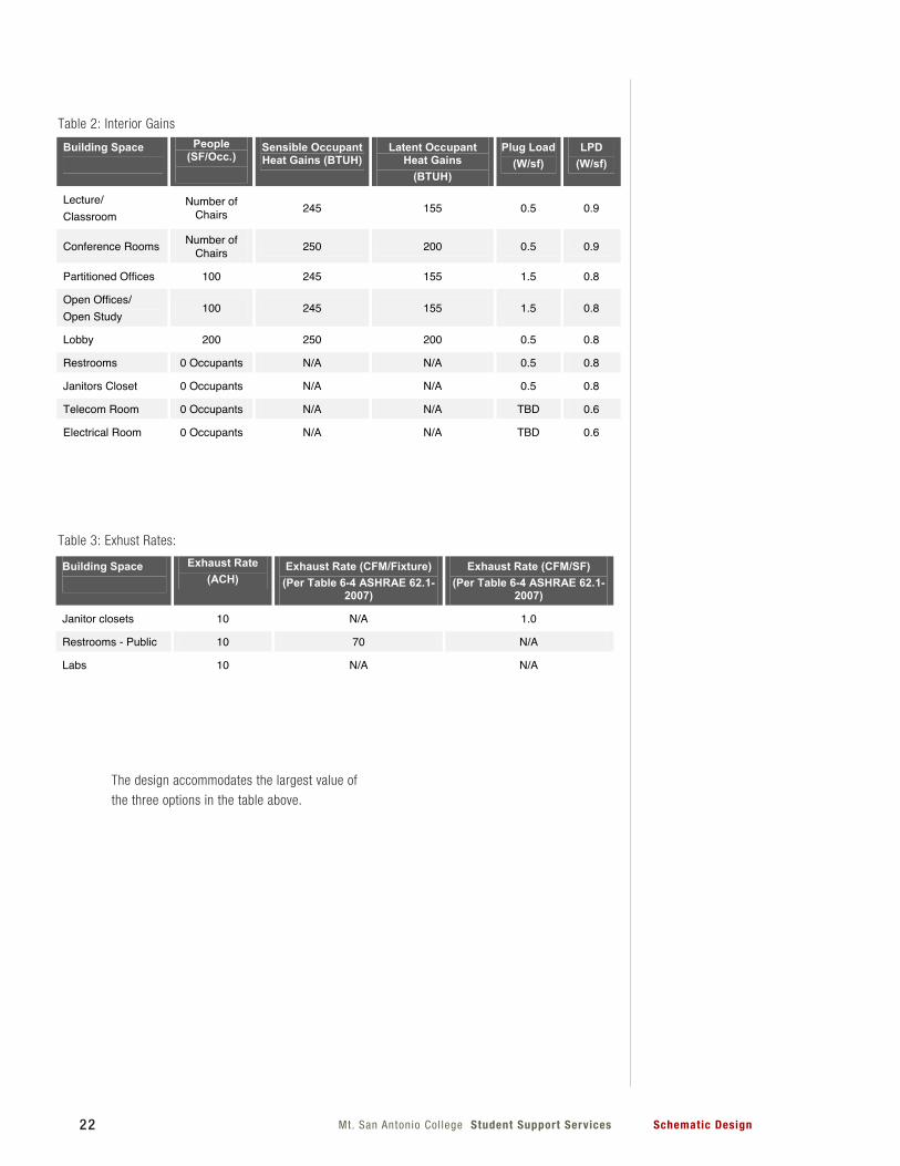
The design accommodates the largest value of
the three options in the table above.
Building Space
Cooling Temp
Heating Temp
Pressurization CO2 Sensor (DCV)
Lecture/
Classroom74°F 69°F Neutral Yes
ConferenceRooms 74°F 69°F Neutral Yes
PartitionedOffices 74°F 69°F Neutral No
OpenOffices/
OpenStudy74°F 69°F Neutral No
Lobby 74°F 69°F Neutral No
Restrooms 74°F 68°F Negative No
JanitorsCloset 74°F N/A Negative No
TelecomRoom 74°F N/A Neutral No
ElectricalRoom 74°F N/A Neutral No
Building Space
People (SF/Occ.)
Sensible Occupant Heat Gains (BTUH)
Latent Occupant Heat Gains
(BTUH)
Plug Load (W/sf)
LPD (W/sf)
Lecture/
ClassroomNumberofChairs 245 155 0.5 0.9
ConferenceRooms NumberofChairs
250 200 0.5 0.9
PartitionedOffices 100 245 155 1.5 0.8
OpenOffices/
OpenStudy100 245 155 1.5 0.8
Lobby 200 250 200 0.5 0.8
Restrooms 0Occupants N/A N/A 0.5 0.8
JanitorsCloset 0Occupants N/A N/A 0.5 0.8
TelecomRoom 0Occupants N/A N/A TBD 0.6
ElectricalRoom 0Occupants N/A N/A TBD 0.6
Table 2: Interior Gains
Table 3: Exhust Rates:
Building Space
Exhaust Rate (ACH)
Exhaust Rate (CFM/Fixture) (Per Table 64 ASHRAE 62.1
2007)
Exhaust Rate (CFM/SF) (Per Table 64 ASHRAE 62.1
2007)
Janitorclosets 10 N/A 1.0
RestroomsPublic 10 70 N/A
Labs 10 N/A N/A
23Mt San Antonio Col lege Student Support ServicesSchematic Design
INDOOR AIR QUALITY
The design meets the minimum requirements
of Title 24 and Sections 4 though 7 of ASHRAE
Standard 62.1-2007, Ventilation for Acceptable
Indoor Air Quality (with errata). The mechanical
ventilation systems are designed using the
ventilation rate procedure (paragraph 6.2 of
ASHRAE Standard 62.1-2007) or Title 24-2008
- whichever is more stringent. For all occupied
spaces the mechanical ventilation rates are
being evaluated at 30% above the minimum
rates of the Ventilation Rate Procedure. The
design may include this 30% increase in
ventilation based on an analysis of the energy
implications.
A permanent Ebtron outdoor air monitoring
system is being provided for all units serving
regularly occupied spaces to ensure that the
ventilation systems maintain design minimum
airflow requirements. All units which include
densely occupied spaces as defined in Title 24
are being provided with carbon dioxide sensors
and demand control ventilation capabilities for
units which include densely occupied spaces
and economizers.
SUSTAINABLE DESIGN STRATEGIES
The project has been designed with a goal of
LEED NC v3, Silver Certification Level. The
building is being designed with the goal of
achieving a 20% energy savings by cost versus
a California Title 24-2005 baseline building.
This energy savings by cost includes the use
of efficient envelope, mechanical, and lighting
systems as well as the campus photovoltaic
array.
Modeling of building performance will be
performed utilizing EnergyPro v5.
The primary system HVAC systems custom
Variable Air Volume Air Handling Units utilizing
campus chilled water and on-site generated
heating hot water. The sustainable design
strategies are described in more detail in the
following section.
The building envelope components shall be
selected to optimize daylighting opportunities
while minimizing heat gain or loss from the
building. The building envelope includes:
Exterior Walls:
Type 1: Centria Formawall Series 3” Insulated
Metal Panel with R-21 insulation
Type 2: Exterior Plaster (Brick Veneer) over 3”
Polyiso Foam Insulation. R21.
Roof:
Tapered rigid insulation over metal deck R30
with white PVC Sarnafil single ply roof.
Windows:
Type 1: PPG 1” Low-E Insulated Glazing;
Center of Glass U=0.29 and Center of Glass
SHGC=0.28
Type 2: Kawneer 1600UT store-front system
The LEED points under NC v3 which are being
pursued as they pertain to mechanical are as
follows:
- EA Prerequisite 2 - Minimum Energy
Performance: project is being modeled in
EnergyPro v5. Building and equipment is being
modeled with input from other trades, i.e.,
Architect, etc. A minimum of 10%, by cost,
above a baseline building per Title 24-2005 is a
prerequisite and is required in order to achieve
any level of LEED Certification.

24 Mt. San Antonio Col lege Student Support Services Schematic Design
engineer is providing a calculation which will
indicate the run-time necessary to achieve the
HVAC flush-out as required by the LEED credit
based on the scheduled mechanical units. This
flushout period is provided in the specifications
as part of the contract documents. If the GC
decides to pursue the flushout per Option 1
of this credit, the GC will be responsible for
coordinating the actual flush-out procedure and
incorporating into the construction schedule. As
a requirement of this credit, the flushout must
occur while maintaining an internal temperature
of at least 60˚F and relative humidity no higher
than 60%. The GC will document the LEED
credit and confirm that the flushout was done in
accordance with the LEED credit requirements.
The mechanical engineer will not be responsible
for pursuing this credit under Option 2 – Air
Testing.
- EQ Credit 4.1 - Low-Emitting
Materials & Sealants: This credit requires
input from multiple trades. The mechanical
scope includes the specification of low-VOC
adhesives and sealants for mechanical systems.
In general, this includes duct sealant but may
include additional adhesives and sealants
as required for this project. These low-VOC
adhesives and sealants will apply only to those
applied inside the building weatherproofing
system.
- EQ Credit 7.1 - Thermal Comfort –
Design: The HVAC systems has been designed
with the goal of achieving compliance with
ASHRAE standard 55-2004.
Primary HVAC Systems
The building HVAC requirements is being served
by two custom variable air volume (VAV) air
handling units (AHU) with chilled water coils
and heating hot water coils. The two units are
provided with single-duct terminal VAV boxes
with reheat coils. The telecom and electrical
rooms are provided with split systems that are
stand alone for 24/7 operation.
- EA Prerequisite 3 - Fundamental
Refrigerant Management: HVAC equipment
in the building is being selected which does
not contain CFC refrigerants. In addition, all
existing central plant equipment which is
connected to the Student Services Annex will
require compliance with this prerequisite. This
equipment is being evaluated for confirmation
that it meets the requirements of the credit.
This is a prerequisite and is required in order to
achieve any level of LEED Certification.
- EA Credit 1 - Optimized Energy
Performance: The energy model, as indicated
under EApr2, also applies to this credit. The
building envelope, mechanical systems, DHW,
and indoor and outdoor lighting systems
are being modeled to show an energy cost
reduction versus a baseline building as
prescribed by the California Energy Code – Title
24-2005.
- EQ Prerequisite 1 - Minimum IAQ
Performance: All spaces are being designed to
meet the ventilation and exhaust requirements
of ASHRAE standard 62.1-2007 as they pertain
to this credit.
- EQ Credit 1 - Outdoor Air Delivery
Monitoring: This credit will be achieved by
utilizing Ebtron outdoor airflow measuring
stations on all units which serve regularly
occupied spaces. This includes AHU-1 and
AHU-2. Also, CO2 sensors will be provided in all
densely occupied spaces and connected to the
EMS system.
- EQ Credit 2 - Increased Ventilation:
The potential to achieve this credit is being
evaluated as the design progresses. This credit
requires a 30% increase of OSA in each system
from the minimum required ASHRAE 62.1-2007
levels. The tradeoffs between energy efficiency
and quantity of outside air are being evaluated
and the ability to pursue this credit will be
determined.
- EQ Credit 3.2 - Construction IAQ
Management Plan – Before Occupancy: The
incorporation of this credit falls under the scope
of the General Contractor in coordination with
the mechanical contractor. The mechanical
25Mt San Antonio Col lege Student Support ServicesSchematic Design
Air Handling Units (AHU)
The building has two VAV Air Handling Unit
(AHU-1 and AHU-2) located in the mechanical
well to serve the HVAC needs of the entire
building. The units are provided with a chilled
water coil and, if required, a hot water heating
coil. AHU-1 and AHU-2 include a supply and
return fan operating on variable frequency
drives. The supply and return fan are sized with
a maximum external static pressure of 1.75”
WC and 0.75” WC, respectively. The units are
provided with a 100% outside air economizer
with demand control capabilities.
The units include a work light inside each air
handler, external zinc fittings, and back-draft
dampers installed in both the supplied and
return end of each air handler. The heating
and cooling coils are sized for a maximum face
velocity of 400 fpm and have a stainless steel
condensate drain pans.
Air filters shall be rigidly supported, extended
area type, U/L listed as Class 2, Minimum
Efficiency Reporting Value (MERV) rating of 13
per ASHRAE Standard 52.2-2007, 12-inch thick
with a universal gasketed-holding frame.
All units are provided with an Ebtron outdoor
airflow measuring station to monitoring outdoor
airflow CFM. This information shall be provided
to the EMS system for control and monitoring.
Carbon dioxide levels are monitored throughout
the densely occupied (≥ 25 people per 1,000
ft2) spaces. The measurement of carbon
dioxide levels in spaces served by AHU-1 and
AHU-2 will allow the building automation system
to reduce the amount of outside air brought
into the building when spaces have reduced
occupancy. There are differential pressure
sensors that measure the difference in pressure
between the inside and the outside of the
building. This reading is used to ensure that the
building remains positively pressurized.
Telecom Rooms
The inter-building distribution frame (IDF)
closets have electronics that require 24/7
cooling. Each space is provided with a ductless
split system, with either a ceiling mounted
fan coil or a wall mounted fan coil. These
systems have a low ambient temperature
feature to allow them to provide cooling when
it is cold outdoors. The capacity of each unit
is approximately 18,000 Btu/hr. The units use
R410a, a non-ozone depleting refrigerant. The
outdoor units are located on the high roof level.
Electrical Rooms
The electrical rooms have electronics that
require 24/7 cooling. Each space is provided
with a ductless split system, with either a
ceiling mounted fan coil or a wall mounted
fan coil. These systems have a low ambient
temperature feature to allow them to provide
cooling when it is cold outdoors. The capacity
of each unit is approximately 18,000 Btu/hr.
The units use R410a, a non-ozone depleting
refrigerant. The outdoor units are located on the
high roof level.
Exhaust Systems
General building exhaust is provided for the
restrooms, janitor closets, and labs. The
exhaust fans are located on the roof. The
exhaust fans shall be manufactured by
Greenheck, Loren Cook, or equal.
Duct Systems and Materials
The supply/return air duct systems are
galvanized steel of minimum 4-inch water
gauge pressure class for mains. Branch ducts
are minimum 2 inch class. Sealing, reinforcing
and supporting according to SMACNA
standards. Ductwork has 1.5” thick foil faced
thermal insulation to minimize heat gain, loss,
and prevent condensation. Exposed supply air
ducts in mechanical rooms and in duct shafts
are double wall insulated sheet metal.
26 Mt. San Antonio Col lege Student Support Services Schematic Design
used. Diffuser do not include volume dampers.
Return grilles are required to be 2’x2’. Provide
45 angled blades for perforated face. Exhaust
grilles are 45 angle blade type.
Hydronic Systems
Chilled water services from the campus
central plant serves this building. Local energy
metering includes Onicon Btu meter for chilled
water. Chilled water coils are selected for an
EWT and LWT of 42/62°F, respectively. Heating
hot water coils are selected for an EWT and
LWT of 180/140°F, respectively. Chilled water
is being extended from the existing valve pit
located on the south east side of the proposed
facility with 6”chilled water.
Heating hot water services are provided via an
on-site gas-fired boiler located in the 2nd floor
mechanical room. Heating hot water coils are
selected for an EWT and LWT of 180/140°F,
respectively.
Piping Materials
Underground chilled water piping are pre-
insulated Polyvinyl Chloride (PVC) pipe with
high-density polyethylene (HDPE) jacket, push-
on joints, with Mega-lug connections.
Chilled water and heating hot water piping
within the building: 3” and larger, Schedule 40
black weld steel pipe ASTM A53, with 1-1/2”
thick heavy density fiberglass with vapor barrier
jacket. Insulation for all outdoor piping shall be
covered with aluminum jacket.
Chilled water and heating hot water piping
within the building: 2-1/2” and smaller, Type
“L”, hard drawn copper tube, with 1-1/2” thick
heavy density fiberglass with vapor barrier
jacket. Insulation for all outdoor piping shall be
covered with aluminum jacket.
Refrigerant piping: Type “L”, hard drawn copper
tube, with 1” foam insulation.
Round ducts are used to the maximum extent
possible. As duct size increases, flat oval
shape is preferred; rectangular ducts limited
to areas of space restriction with a maximum
aspect ratio of 3:1. If due to a structural
clearance constraint, duct aspect ratio may be
increased and/or duct cross-section reduced if
upstream transition includes angles of 60 or
less and downstream transition includes angles
of 30 or less.
The supply air ducts from central air handling
unit discharge up to terminal units has been
sized for friction losses between 0.15 to 0.25
inches WG/100 feet but not to exceed a velocity
of 2,000 fpm. The design of constant volume
systems is towards the low end of the friction
range and variable volume systems to the
high end of the range for the full CFM without
diversity.
Size supply branch ducts, return air ducts, and
general (e.g., toilet) exhaust ducts for friction
losses between 0.08 and 0.12 inches WG/100
feet but not to exceed 1600 fpm. Minimum
duct size is 8” x 12”, 12” x 8”, 10” x 10”, 10”
square, or 6” round regardless of flow. If air
inlet or outlet neck size is smaller than these
minimums, the final run out of less than seven
feet in length may be neck size.
Minimum general exhaust duct velocity is 1,200
fpm; maximum is 1,600 fpm.
Exhaust duct system will be galvanized steel of
minimum 2-inch water gauge pressure class.
There will be no insulation provided for exhaust
ductwork.
Grilles, Registers, and Diffusers
In all spaces a 2’x2’ or 1’x1’ perforated face
(Titus model PAS or equal) or modular core
diffusers (Titus model MCD or equal) are
27Mt San Antonio Col lege Student Support ServicesSchematic Design
VIBRATION ISOLATORS
All rotating and reciprocating equipment is
provided with vibration isolation systems
including seismic restraint to prevent
transmission of vibration to structure. Air
handlers only have the fans isolated.
CONTROLS
The building automation/energy management
system (BMS) is compatible with the existing
campus Automated Logic BMS controls. The
system is able to integrate multiple building
functions, including equipment supervision
and control, alarm management, energy
management, and historical data management
and archiving. In addition, the lighting schedule
interfaces with the HVAC controls for single
schedule input.
All control panels are stand-alone in memory,
networking, and control operations. The
design of the controls is in a modular format,
permitting future expansion capabilities. The
system monitors and controls equipment
according to the sequence of operation, as well
as additional input and output points.
The equipment operates based upon an
operator-defined schedule for each system. The
control system is compatible with the campus
control system and communicates without the
use of gateways or modifiers.
The provided controllers do not not utilize any
proprietary drivers or jar files. The controllers
use the latest stable firmware release from the
manufacturer. Space temperature and CO2
sensors have a digital display with adjustable
set points. All relays utilized in the control
system shall be IDEC relays with status lights.
DDC POINTS
At a minimum, the following control points
(Ao, Ai, Di, Do) are provided. For each input or
output device, provide a unique and discrete
control point. Ganging points together is not
acceptable.
•Spaces (as appropriate per design criteria):
o Room Temperature
o CO2 Level
o Occupancy Sensor
o Building Static pressure sensor
•Air Handlers Units (each, as appropriate):
o Supply air temperature
o Mixed air temperature
o Return air temperature
o Relief air damper control
o Mix air damper control
o Outside air damper control
o Return plenum pressure
o Differential pressure transducer
across filters
o Supply duct static pressure sensor
o Smoke detector
o Building pressurization control &
sensors
o Outside air flow station
o Economizer damper control
o Supply fan status
o Relief fan status
o Supply fan VFD feedback
o Relief fan VFD feedback
o Supply fan enable
o Relief fan enable
o Supply fan VFD speed control
o Relief fan VFD speed control
o Supply fan amp draw
(non VFD supply fan)
•Constant speed exhaust fans, ventilators,
transfer fans, and smoke control fans (each):
o Start/Stop
o Amp/ draw
28 Mt. San Antonio Col lege Student Support Services Schematic Design
•Building/Utilities
o Outdoor temperature
o Outdoor air humidity
o Outdoor CO2 Level
o Gas Flow Totalizer – Total Building
o Electrical Demand and
Consumption
o Chilled Water Energy Use
o Heating Hot Water Energy Use
•Lighting
o Indoor Lighting kW-hr
o Outdoor Lighting kW-hr
2.5 PLUMBING
Plumbing Systems:
Plumbing for the New Student Services
Annex Building will incorporate the objective
of providing a system that complies with the
occupant needs and provides a more efficient
and safer environment. The scope of Plumbing
includes plumbing fixtures, domestic water
heating equipment, domestic water, waste/vent,
storm drain and natural gas piping distribution
systems.
Applicable Codes:
California Building Standards Administrative
Code (Title 24, Part I), 2010
California Building Code (Title 24, Part 2), 2010
California Plumbing Code (Title 24, Part 5),
2010
California Energy Code (Title 24, Part 6), 2010
California Fire Code (Title 24, Part 9), 2010
California Reference Standards Code (Title 24,
Part 12), 2010
Domestic Cold Water System:
The domestic cold water service line and
backflow prevention for the building will provide
for all domestic cold water demands as well
as industrial non potable cold water needs. A
central backflow prevention device will separate
the domestic and industrial services. Domestic
water will be distributed to plumbing fixtures,
hose bibs and water heaters via gravity and
thru the city street main water pressure. Water
velocity will not exceed 8 feet per second.
Domestic Hot Water System:
A condensing type, high efficient tank type
gas fired water heater will be provided on
the second floor mechanical room. This
service will provide for all domestic hot water
demands and will be distributed via gravity,
re-circulated by a closed loop domestic water
in-line circulating pump with no more than ½
horsepower electrical load. A seven (7) day
twenty four hour programmable time clock,
aqua stat and temperature sensors will be
provided to maintain the hot water temperature
within 105 degree F to 120 degree F range. All
hot water distribution piping will be insulated
with appropriate thickness of insulation and fire
retardant jacket. Water velocity will not exceed
5 feet per second.
Plumbing Fixtures:
Water conserving fixtures will be selected that
will include high efficient toilets rated at 1.28
gallon per flush, high efficient Urinals rated
at 0.5 gallon per flush and sensor activated
electronic low flow lavatory faucets rated at 0.5
gallon per minute. These fixtures will result in
water savings of 30% reduction of the building
water usage. Groups of fixtures on each floor
will be provided with isolation valves for ease
of maintenance. Each plumbing fixture will
also be provided with individual isolation valves
(fixture stops) for maintenance purposes. Water
hammer arrestors and trap primer valves for
floor drains will be provided as required in the
wall behind access panels.
Sanitary Drainage and Vent Systems:
Soil/waste drainage piping will be provided
to each domestic plumbing fixture. Sanitary
29Mt San Antonio Col lege Student Support ServicesSchematic Design
drainage ventilation piping will be provided to
each domestic plumbing fixture or trap and will
terminate at various locations on the roof.
Emergency drainage will be provided for the fire
sprinkler system. Hub drains will be provided
for fire sprinkler system and will be connected
to the sanitary drainage system.
Sump pumps shall be provided as required for
elevator pits and low grade areas and shall be
submersible, duplex with guide rail for easy
removal.
Storm Drain System:
Storm drain service will discharge through
roof drains and rainwater leaders connecting
to the site storm drainage lines. A separate
overflow drainage system will be provided and
will daylight at building overhangs or exterior
walls. The Civil Engineer will collect the roof
drainage discharge at 5’-0” from the building
perimeter to central collection points including
any perimeter exterior drains.
Indirect Waste and Drainage Systems:
HVAC condensate drainage piping will be
provided to each HVAC unit. Such piping will
drain to an indirect waste connection to the
sanitary soil/waste system via either tailpiece
connection at the nearest lavatory or sink, or a
fixed air gap mounted within a stainless steel
panel in wall. Roof air handler condensate shall
drain to roof mounted floor sinks adjacent to
air handlers. Floor sinks shall have elevated
rims above roof level to prevent drainage of
rainwater.
Natural Gas System:
Natural gas for the building will be supplied
from the existing on-site medium pressure
gas system via a new polyethylene (P.E) pipe
extended from the south-west of the project
site. A new gas connection will be provided for
the building comprising of a) sub-gas meter
assembly (at clients request) b) gas pressure
regulator c) automatic gas seismic shut-off
valve. The sub-gas meter will give the Campus
Facilities the capability to monitor the buildings
gas consumption. Gas supply into the building,
downstream of the regulator assembly will be
distributed at low pressure to all natural gas
appliances and any other equipment with gas
requirements inside the building.
All piping components subject to sweating or
heat loss will be insulated with appropriate
thickness of insulation and fire retardant jacket.
Domestic Systems Piping Materials
HW, CW: Copper tube, Type L, with wrought
copper fittings and brazed or soldered joints.
G: Schedule 40 black steel with
threaded galvanized malleable iron fittings as
required.
W, V: Heavy duty cast iron. No hub,
minimum 1/4” per foot slope.
CD: Type “L” copper, insulated, minimum
1/4” per foot slope.
RD, OD: Heavy duty cast iron. No hub,
minimum 1/4” per foot slope.
Noise and Vibration Control:
Products, including toilets, urinals, and
flush valves, will be selected to minimize the
generation of noise and vibration into the
domestic water system. A minimum 1/4-inch
resilient material will be provided between
domestic hot and cold water piping, waste
and vent lines and the building structure.
Specific noise and vibration control measures
for Domestic Water, Waste and Vent Piping
include:
1. Horizontal Suspended: Tolco Clevis Hanger
with felt. Provide cable seismic restraints if
required by code.
2. Horizontal Supported: Elmdor Stoneman
Trisolator
30 Mt. San Antonio Col lege Student Support Services Schematic Design
California Building Code (Title 24, Part 2)
California Electrical Code (Title 24, Part 3)
California Energy Code (Title 24, Part 6)
California Fire Code (Title 24, Part 9)
California Referenced Standards Code (Title 24,
Part 12)
Reference Standards and Guidelines:
NFPA 72: National Fire Alarm Code
1999 Edition of the Illuminating Engineering
Society of North America Handbook
Design Criteria
Following are design voltages and load
calculation criteria for the proposed building.
Design Voltages
Secondary voltage, Emergency/standby:
277V, 1 phase, 3 wire
120V, 1 phase, 3 wire
Secondary voltage, Normal:
480Y/277V, 3 phase, 4 wire
208Y/120V, 3 phase, 4 wire
3. Riser Supports: Hubbard Holdrite Silencer
#278 between riser clamp and building
structure
4. Partition Penetrations: Coordinate with
other trades to avoid contact where plumbing
penetrations occur.
Plumbing Seismic Design Criteria:
1. Horizontal equals plus or minus 2 1/2
inches.
2. Vertical equals zero inches.
2.6 ELECTRICAL
The design of the electrical system for the new
Mt SAC Student Services Annex building will
encompass interior and exterior lighting, power
distribution systems and a fire alarm system. All
these systems will be designed to provide the
user with maximum flexibility. All equipments
that form part of these systems will be selected
for durability and ease of maintenance that are
consistent with the current campus standards. .
The design of the building’s lighting and power
are essential in achieving the College’s goal of
sustainability, improved energy performance,
and LEED certification.
The new Student Services Annex is located on
the Mt. San Antonio College campus adjacent to
the existing Student Services Building.
The following applicable codes and standards
will be referenced for the electrical design for
the proposed building.
Applicable Codes:
California Building Standards Administrative
Code (Title 24, Part 1)
31Mt San Antonio Col lege Student Support ServicesSchematic Design
located in the second floor.
Proposed Electrical Distribution System
The proposed building will be served from
existing Building 9B (Student Services)
480/277V, 1000A bus Switchboard ‘HDS’.
A new Switchboard ‘SWBD-SSA’ rated at
600Amp copper bus, 480/277V, 3 phase, 4
wire, 65kAIC will be specified for the proposed
building and to be located in the second floor
main electrical room. A 400amp 3 pole breaker
will be installed in the existing Switchboard
‘HDS’ in building 9B and the feeders will be
routed to proposed Student Services Annex
main electrical room and to be connected
to new Switchboard ‘SWBD-SSA’. The new
Switchboard ‘SWBD-SSA’ will be specified with
branch circuit breakers to feed the lighting
panels and mechanical equipments.
A 225kVA, 480-208/120V, 3 pahse 4 wire
transformer will be specified and to be located
closer to Switchboard ‘SWBD-SSA’ . The
transformer will be K=4, dry-type with copper
windings with 150 degree temp. Rise.
Downstream o f the transformer, 1000amp
copper bus 208/120volt, 3 pahse, 4 wire
Distribution Board ‘DB-SSA’ with main breaker
section will be specified to support building
120/208V load requirements.
Each floor will have 120/208V and 480/277V
panelboards. Each panelboard will be specified
as 225amp copper bus with 150amp main
circuit breaker and 42 circuit branch circuit
breakers.
Building two elevators will be served by two
breakers located on “SWBD-SSA”.
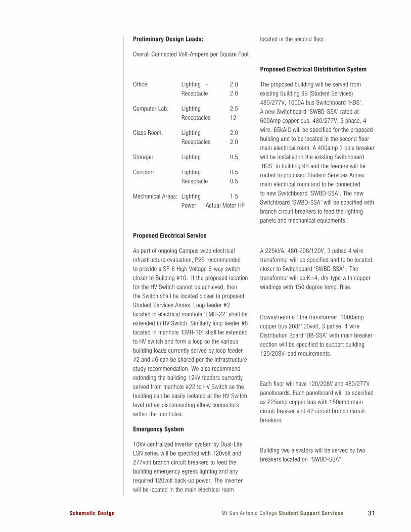
Preliminary Design Loads:
Overall Connected Volt-Ampere per Square Foot
Office: Lighting - 2.0
Receptacle 2.0
Computer Lab: Lighting 2.5
Receptacles 12
Class Room: Lighting 2.0
Receptacles 2.0
Storage: Lighting 0.5
Corridor: Lighting 0.5
Receptacle 0.5
Mechanical Areas: Lighting 1.5
Power Actual Motor HP
Proposed Electrical Service
As part of ongoing Campus wide electrical
infrastructure evaluation, P2S recommended
to provide a SF-6 High Voltage 6-way switch
closer to Building #10. If the proposed location
for the HV Switch cannot be achieved, then
the Switch shall be located closer to proposed
Student Services Annex. Loop feeder #2
located in electrical manhole ‘EMH-22’ shall be
extended to HV Switch. Similarly loop feeder #6
located in manhole ‘EMH-10’ shall be extended
to HV switch and form a loop so the various
building loads currently served by loop feeder
#2 and #6 can be shared per the infrastructure
study recommendation. We also recommend
extending the building 12kV feeders currently
served from manhole #22 to HV Switch so the
building can be easily isolated at the HV Switch
level rather disconnecting elbow connectors
within the manholes.
Emergency System
10kV centralized inverter system by Dual-Lite
LSN series will be specified with 120volt and
277volt branch circuit breakers to feed the
building emergency egress lighting and any
required 120volt back-up power. The inverter
will be located in the main electrical room
32 Mt. San Antonio Col lege Student Support Services Schematic Design
Lighting
Light fixtures and systems will be selected for
efficiency, durability, maintenance ease, and to
accentuate the area architecture. Indoor lighting
will be tailored to building’s needs and theme.
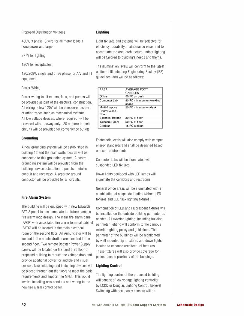
The illumination levels will conform to the latest
edition of Illuminating Engineering Society (IES)
guidelines, and will be as follows:
Footcandle levels will also comply with campus
energy standards and shall be designed based
on user requirements.
Computer Labs will be illuminated with
suspended LED fixtures.
Down lights equipped with LED lamps will
illuminate the corridors and restrooms.
General office areas will be illuminated with a
combination of suspended indirect/direct LED
fixtures and LED task lighting fixtures.
Combination of LED and Fluorescent fixtures will
be installed on the outside building perimeter as
needed. All exterior lighting, including building
perimeter lighting will conform to the campus
exterior lighting policy and guidelines. The
perimeter of the buildings will be highlighted
by wall mounted light fixtures and down lights
located to enhance architectural features.
These fixtures will also provide coverage for
pedestrians in proximity of the buildings.
Lighting Control
The lighting control of the proposed building
will consist of low voltage lighting controller
by LC&D or Douglas Lighting Control. Bi-level
Switching with occupancy sensors will be
Proposed Distribution Voltages
480V, 3 phase, 3 wire for all motor loads 1
horsepower and larger
277V for lighting
120V for receptacles
120/208V, single and three phase for A/V and I.T
equipment.
Power Wiring
Power wiring to all motors, fans, and pumps will
be provided as part of the electrical construction.
All wiring below 120V will be considered as part
of other trades such as mechanical systems.
All low voltage devices, where required, will be
provided with raceway only. 20 ampere branch
circuits will be provided for convenience outlets.
Grounding
A new grounding system will be established in
building 12 and the main switchboards will be
connected to this grounding system. A central
grounding system will be provided from the
building service substation to panels, metallic
conduit and raceways. A separate ground
conductor will be provided for all circuits.
Fire Alarm System
The building will be equipped with new Edwards
EST-3 panel to accommodate the future campus
fire alarm loop design. The main fire alarm panel
‘FACP’ with associated fire alarm terminal cabinet
‘FATC’ will be located in the main electrical
room on the second floor. An Annunciator will be
located in the administration area located in the
second floor. Two remote Booster Power Supply
panels will be located on first and third floor of
proposed building to reduce the voltage drop and
provide additional power for audible and visual
devices. New initiating and indicating devices will
be placed through out the floors to meet the code
requirements and support the MNS. This would
involve installing new conduits and wiring to the
new fire alarm control panel.
AREA AVERAGEFOOTCANDLES
Office 50FCondeskComputerLab 50FCminimumonworking
spaceMultiPurposeRoom/ClassRoom
50FCminimumondesk
ElectricalRooms 30FCatfloorTelecomRoom 50FCatfloorCorridor 15PCatfloor
33Mt San Antonio Col lege Student Support ServicesSchematic Design
2.7 COMMUNICATION/IT SYSTEMS
Telecommunications Infrastructure
The Telecommunications Infrastructure in
the building will provide reliable, flexible and
scalable access to the College’s Information
Technology resources including, voice, data
network, administrative computing and
student services. The Telecommunications
infrastructure will consist of an MDF and a Data
Center, cable distribution/containment systems,
communications cabling and provision for a
wireless network overlay.
The new Student Services Annex building will
have dual pathway entry systems to comply with
the Mt. SAC master plan and design criteria.
One of the entries will connect from TMH #10
located to the north of the building and the
other will connect to TMH #22 located south of
the building.
The minimum fiber cable is to be a hybrid 18
multi-mode/18 single-mode cable from the
Data Center and a 25-pair copper cable from
the MDF that is the current primary Minimum
Point of Entry (MPOE). The secondary entry
will be an 18 multi-mode/18 singlemode from
building L7-A. The Multi-mode is 62.5 micron.
The copper cable is for alarms, faxes and any
other analog needs the building may have. The
regular voice service for this building shall be
handled by the College’s Voice over IP System.
There shall be fiber from the Data Center to
both manholes as noted above and into the
building from two directions.
This is a new 3 level structure being built
adjacent to the existing Student services
Building and will have a BDF-2.1 on the
second level for the main entry room and two
IDF’s one on the first level and one on the third
level. The BDF-2.1 will house the entry conduits
and the fiber and copper backbone cables.
The fiber cables will be terminated on 72 port
fiber termination units (FTU’s) and the copper
cable will have a protector panel equipped
with solid-state protector modules sized at 25
pairs. The first and third levels are to be feed
with a fiber and copper riser systems sized
per the District’s design criteria. The fiber and
provided in larger offices. In order to utilize
the “Savings by Design” program and
capable of reducing energy consumption
to comply with Southern California Edison
(SCE) Automated Demand Response (ADR),
the entire building will be designed with
multiple low voltage lighting controller
(Micro panel or Satellite panel) with six
relays and will be located in the ceiling
space. This system is designed to
maximize energy savings, lighting flexibility/
variability and user friendliness while
minimizing disruption to the learning
environment. Single level switches will be
provided in service areas and utility rooms.
Automatic shut off for all other area not
control by sensors will be accomplished
through low voltage lighting control panel
and override switches in compliance with
current California Energy Code. Likewise
corridor lighting will be controlled with
lighting control panel and override switches
in compliance with CEC code. Occupancy
sensors consistent with campus standards
and bi-level switches will be provided in all
offices.
Architectural dimming systems will be
provided in conference rooms as required.
Building low voltage lighting controller
(LC&D or Douglas Lighting Control ) will be
provided with interface to existing campus
Building energy management system,
Automated Logic Controller.
Outdoor lighting will be controlled by Exergy
Controller and will be incorporated into
existing Web based control system.
LED Exit signs will be provided at all exits
and along the path of egress. Emergency
lighting (light fixtures on emergency power)
will be provided in labs, pathways, corridors
and public access areas and illumination
will conform to the current CBC requirement
of a minimum one foot candle level at floor
level during loss of normal power.
34 Mt. San Antonio Col lege Student Support Services Schematic Design
copper risers cables will be home run from
the IDF’s to the BDF and sized to meet the
District design criteria. Two 25 pair for copper
riser cables (one to each IDF), and Two 12
multimode 12 single mode hybrid cable (one
to each IDF). The BDF and IDF’s will be tie
with a grounding system consisting of a 3/0
ground wire connected to individual bus bars
in each IDF and BDF. The ground system will
be connected to the main building ground in
the electrical room.
In designing the Telecommunications for this
building, there are resources to be followed.
They are the MSAC Technology Standards.
TELECOMMUNICATIONS EQUIPMENT ROOMS
Building Distribution Frame Room
The Building Distribution Frame (BDF) room in
this building will serve as the primary location
for the equipment to support data network and
telephone functions. The equipment in this
room will operate on a 24 hour a day basis.
Because College functions continue to become
more reliant on technology, the BDF room will
be required to provide 99.9% reliability for
power and air conditioning systems.
The BDF Room is the recognized origination
point to the building’s backbone and horizontal
pathways.
.AC-grade plywood, 8 ft. high with a minimum
thickness of 0.75 in. shall be provided around
the perimeter of the room. Plywood shall be
either fire-rated or treated on all sides with at
least two coats of fire resistant paint.
An overhead cable tray system shall be
provided for routing cables between cross-
connections, equipment, and backbone
pathways. Conduits shall be used to connect
the eastern half of the building to the BDF
located in the western part of the building.
The room shall be designed to support up to
two racks that shall house cable terminations,
switching equipment, and other equipment
serving the building’s technology needs.
Each rack shall consist of a modular EIA 19”
mounting frame with a minimum of 84” (45
RU’s) space for equipment in the vertical
plane and manufactured by Chatsworth
Products as per College standards.
Ladder racks shall be provided within the
BDF to route cables to or from sleeves and
conduits to terminations within the equipment
racks.
The room shall provide space and maintain
a suitable operating environment for the
termination of backbone and campus cabling
and house centralized communications
and/ or computer equipment (such as core
switches and servers). The room shall support
the termination of the station cabling for the
entire building. The BDF room should be a
minimum of 80 square feet in size.
This room will allow for two equipment racks..
Mechanical System (HVAC) Requirements for BDF -
Provide HVAC that shall maintain continuous
and dedicated environmental control (24
hours per day, 365 days per year). Maintain
positive pressure with a minimum of one air
change per hour. Provide:
o Temperature 70 degrees F +/- 10 degrees
o Relative humidity 50% +/- 20%
Estimated Heat Loads: 5,000 to 7,500 BTU
per equipment cabinet or rack.
Electrical System Requirements for BDF
o Lighting
We will provide a minimum equivalent of 500
lux (50 foot-candles) measured 1 m (3 ft)
above the finished floor. Locate light fixtures
a minimum of 2.6 m (8.5 ft) above the
finished floor. Emergency lighting systems
which operate on trickle-charge storage
batteries are desirable as a safety precaution
in the event of an inadvertent power outage.
o Power
35Mt San Antonio Col lege Student Support ServicesSchematic Design
The IT cabling systems shall be distributed
throughout the building via a series of
infrastructure elements that include conduits
and cable trays. This infrastructure establishes
dedicated pathways for backbone and horizontal
cable distribution.
The communication cable distribution system
includes the pathway and support hardware
which concentrates, supports and protects
horizontal cable between its origination point
in the BDF and the telecommunications outlet
location. It also provides a permanent pathway
that facilitates the addition or replacement of
cable over time with minimal disruption.
Communications Cabling Systems
Standard Network outlets shall be provided
in all offices, classrooms, conference rooms
and support spaces throughout the building.
The cabling system shall provide a high
level of flexibility and resilience, and shall
provide sufficient bandwidth to support future
generations of technology without the need for
re-cabling. The College uses a Voice over IP
System. The standard network outlet for the
campus is a Three-Data Outlet with the first
jack being Blue, the second is Gray and the
third is Yellow. If a fourth jack is required, it will
be Black. The Category 6 cable for each jack
will be of the corresponding color, for instance,
a blue cable for the blue jack, gray cable for
the gray jack, etc. As outlets are specified
throughout this Design, a Three Data Outlet
means the standard outlet as described above.
The communications cabling system shall
include:
Inter-Building Conduits and Cables - Conduits
and fiber and copper cables from the Campus
infrastructure shall be provided to serve this
building from the Data Center and the MDF on
campus.
The BDF shall be equipped to provide adequate
electrical power. For every equipment rack/
cabinet, provide (1) dedicated non-switched
3-wire, 30A, 120 volt (V) alternating current
(ac) with locking electrical outlets (NEMA L5-
30R) for equipment power, each on separate
branch circuits.
For every equipment rack/cabinet, provide
(1) dedicated non-switched 3-wire, 30A, 208
volt (V) alternating current (ac) with locking
electrical outlets (NEMA L6-30R) for equipment
power, each on separate branch circuits.
Provide separate duplex 120 V AC convenience
outlets (NEMA 5-20R) for tools, test sets, etc.,
located at least 18 in. above the finished floor,
placed at approximately 6 ft. intervals around
perimeter walls and identified and marked as
such. All outlets must be on non switched
circuits.
An electrical subpanel serving each telecom
room shall be included. That panel shall be
sized at a minimum of 225A bus, 120/208V, 3
phase and 4 wire.
o Bonding and Grounding
Provide a copper signal ground bus bar. The
ground lead shall be a 3/0 copper cable
with green insulation, cad-welded to the
Main Building Ground and/or building steel.
All conduits, racks, ladder racks, cable
splice cases, copper cable protectors, cable
aluminum shields and cable trays shall be
bonded to the bus bar using #6 AWG stranded
copper green insulated conductors. The bus
bar in the IDF shall be connected to the bus
bar in the BDF with a 3/0 copper cable with
green insulation.
Bus Bar shall be identified and have a warning
tag directing observer to the IT department is
a grounding connector is found loose. The 3/0
conductor(s) shall be labeled as such and as to
destination.
Cable Distribution / Containment Systems
36 Mt. San Antonio Col lege Student Support Services Schematic Design
Backbone (Riser): (2)25 pair ARMM copper
cables home run from IDF to BDF and (2) 12
multimode 12 singlemode hybrid fiber cables
homerun from the IDF’s to the BDF.
Horizontal (Station): The horizontal cabling
connects each network outlet to the BDF and
IDF’s for voice, data and video connectivity.
It consists of High Performance plenum-
rated Category 6 cable and connectors. The
horizontal cable shall support standards-based
network protocols of up to Gigabit Ethernet. The
horizontal cabling shall be a Structured Cabling
System (SCS) with a warranty of at least 20
years. The Campus standard for the SCS is
Panduit with Belden DataTwist Cabling. There
shall be no substitutions.
Wireless Connection Points: Shall be
distributed throughout the facility to support
wireless network access equipment and
future Radio Frequency Identification (RFID)
equipment. Three-data outlets (hardwired)
shall be provided above the ceiling (T-Bar) for
wireless applications. If placed where there is
hard pan ceiling, install the outlet 6” below the
ceiling.
Common areas, meeting rooms and sufficient
locations throughout the building to provide
100% wireless access shall have wireless
application outlets installed. This includes
the outdoor landscape areas to be shared by
existing Student Services (9B) and proposed
Student Services Annex.
The proposed outlet distribution for this building
is as follows:
Smaller, Cubicle type Office
Three-Data Outlet per desk
Regular Offices for Administrators or Faculty
(2) Three-Data Outlets, on opposite walls but
not door wall
Larger Offices – Deans, Directors
(3) Three-Data Outlets, one on each wall except
door wall
Large Conference Room
(2) Three- Data Outlets on opposing walls
(1) Three-Data Outlet in ceiling for projector
position (1) Three-Data Outlet in floor box
under conference table
Small Conference Room
(3) Three-Data Outlets, one on each wall except
door wall
Classrooms
(1) Three-Data Outlet in floor box or wall
at Instructor’s Position
(1) Three-Data Outlet in ceiling at projector
position
(4) Three-Data Outlets, one on each wall
(1) Voice wall outlet on door wall
Other Areas of Building
Mechanical/Electrical Rooms
A three-data outlet shall be provided in each
mechanical and each electrical area within a
mechanical/electrical room.
These shall be for current or future monitoring/
EMS needs.
One Wall Voice Phone per Mechanical and
Electrical Rooms
Fire Alarm Panel
We shall determine where fire alarm panel shall
be located and whether data or fiber circuits are
required.
Mt. San Antonio Col lege - Student Support ServicesSchematic Design 37
Area Tabulation3.1 PROJECT AREA SUMMARY3.2 SPACE PROGRAMMING SPREADSHEET
3
3.1 PROGRAM AREA SUMMARY
Throughout the Programming and Schematic
Design phase, area spread sheets were tracked
and updated durring each coordination meeting.
Adjustments to initial program were a result of
prioritizing needs of the departments as well as
additions to the initial scope of the project.
In addition to the development and fine tuning
of original program spaces, adjustments were
made in coordination with structural and MEP
requirments.
Noteable changes through the process include
the addition of the Bridge and Aspire Program,
as well as a third story to include a Flexible
Program Space, which also resulted in addition
support spaces and circulation. The addition of
these two deparments brought the GSF of the
building from roughly 10,800 GSF to 22,900
GSF.
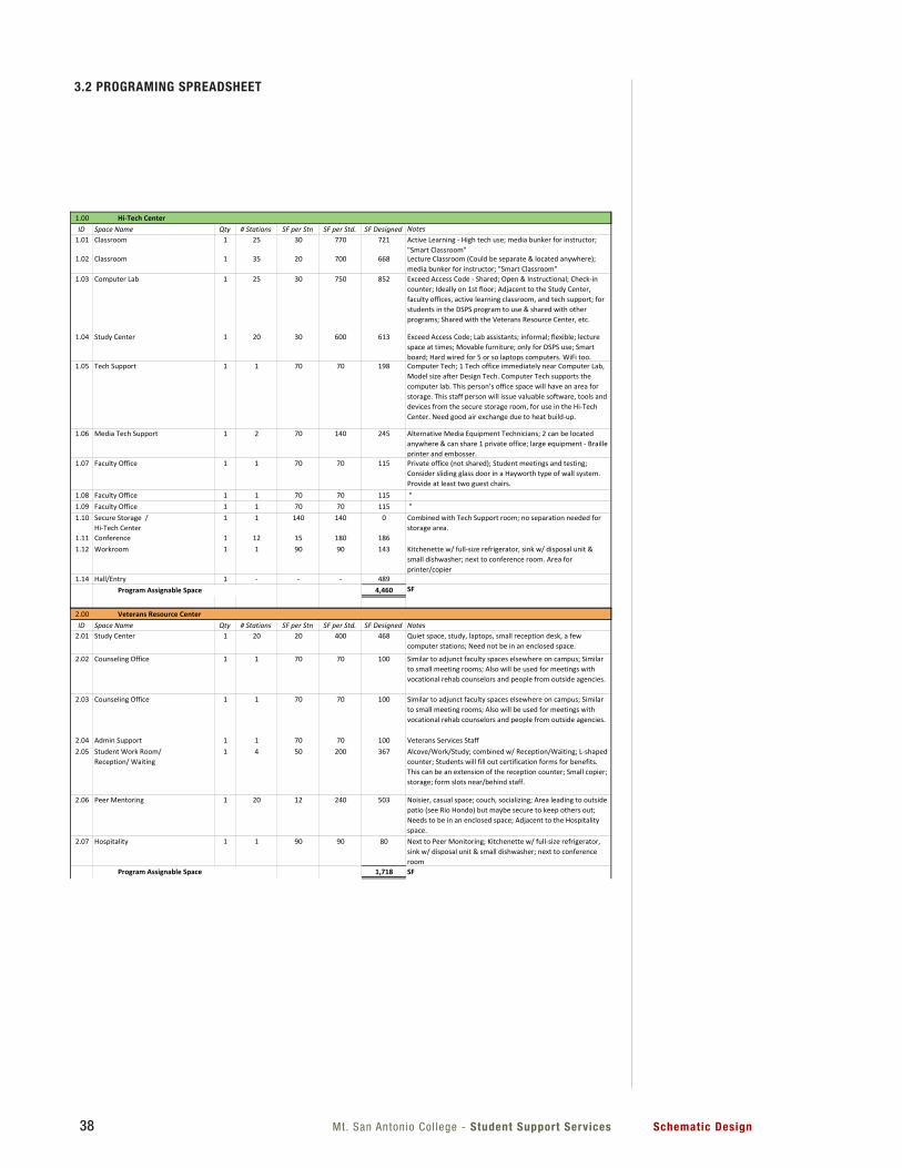
Mt. San Antonio Col lege - Student Support Services Schematic Design38
3.2 PROGRAMING SPREADSHEET
Mt. SAC - Student Support Services Preliminary Space Program 10/31/12
1.00ID Space Name Qty # Stations SF per Stn SF per Std. SF Designed Notes
1.01 Classroom 1 25 30 770 721 Active Learning - High tech use; media bunker for instructor; "Smart Classroom"
1.02 Classroom 1 35 20 700 668 Lecture Classroom (Could be separate & located anywhere); media bunker for instructor; "Smart Classroom"
1.03 Computer Lab 1 25 30 750 852 Exceed Access Code - Shared; Open & Instructional; Check-in counter; Ideally on 1st floor; Adjacent to the Study Center, faculty offices, active learning classroom, and tech support; for students in the DSPS program to use & shared with other programs; Shared with the Veterans Resource Center, etc.
1.04 Study Center 1 20 30 600 613 Exceed Access Code; Lab assistants; informal; flexible; lecture space at times; Movable furniture; only for DSPS use; Smart board; Hard wired for 5 or so laptops computers. WiFi too.
1.05 Tech Support 1 1 70 70 198 Computer Tech; 1 Tech office immediately near Computer Lab, Model size after Design Tech. Computer Tech supports the computer lab. This person’s office space will have an area for storage. This staff person will issue valuable software, tools and devices from the secure storage room, for use in the Hi-Tech Center. Need good air exchange due to heat build-up.
1.06 Media Tech Support 1 2 70 140 245 Alternative Media Equipment Technicians; 2 can be located anywhere & can share 1 private office; large equipment - Braille printer and embosser.
1.07 Faculty Office 1 1 70 70 115 Private office (not shared); Student meetings and testing; Consider sliding glass door in a Hayworth type of wall system. Provide at least two guest chairs.
1.08 Faculty Office 1 1 70 70 115 " 1.09 Faculty Office 1 1 70 70 115 " 1.10 Secure Storage /
Hi-Tech Center 1 1 140 140 0 Combined with Tech Support room; no separation needed for
storage area.1.11 Conference 1 12 15 180 1861.12 Workroom 1 1 90 90 143 Kitchenette w/ full-size refrigerator, sink w/ disposal unit &
small dishwasher; next to conference room. Area for printer/copier
1.14 Hall/Entry 1 - - - 4894,460 SF
Hi-Tech Center
Program Assignable Space
1
Mt. SAC - Student Support Services Preliminary Space Program 10/31/12
2.00ID Space Name Qty # Stations SF per Stn SF per Std. SF Designed Notes
2.01 Study Center 1 20 20 400 468 Quiet space, study, laptops, small reception desk, a few computer stations; Need not be in an enclosed space.
2.02 Counseling Office 1 1 70 70 100 Similar to adjunct faculty spaces elsewhere on campus; Similar to small meeting rooms; Also will be used for meetings with vocational rehab counselors and people from outside agencies.
2.03 Counseling Office 1 1 70 70 100 Similar to adjunct faculty spaces elsewhere on campus; Similar to small meeting rooms; Also will be used for meetings with vocational rehab counselors and people from outside agencies.
2.04 Admin Support 1 1 70 70 100 Veterans Services Staff2.05 Student Work Room/
Reception/ Waiting1 4 50 200 367 Alcove/Work/Study; combined w/ Reception/Waiting; L-shaped
counter; Students will fill out certification forms for benefits. This can be an extension of the reception counter; Small copier; storage; form slots near/behind staff.
2.06 Peer Mentoring 1 20 12 240 503 Noisier, casual space; couch, socializing; Area leading to outside patio (see Rio Hondo) but maybe secure to keep others out; Needs to be in an enclosed space; Adjacent to the Hospitality space.
2.07 Hospitality 1 1 90 90 80 Next to Peer Monitoring; Kitchenette w/ full-size refrigerator, sink w/ disposal unit & small dishwasher; next to conference room
1,718 SF
3.00ID Space Name Qty # Stations SF per Stn SF per Std. SF Designed Notes
3.01 Lobby/Waiting 1 8 12 100 242 Seating for 8 to 10; enclosed lobby (separate from rest of building)
3.02 Reception 1 2 70 140 137 Window for 2 patients (preferably windows are away from the waiting chairs for privacy); 2 staff; room for files (3 pivoting files? ~ 36" square each).
3.03 Treatment Rooms 1 1 120 120 120 Traige + Treatment + Recovery; Cluster near other noisy (non-office spaces); Match size of (E) rooms.
3.04 Treatment Rooms 1 1 120 120 120 Traige + Treatment + Recovery; Cluster near other noisy (non-office spaces); Match size of (E) rooms.
Veterans Resource Center
Student Health
Program Assignable Space
2
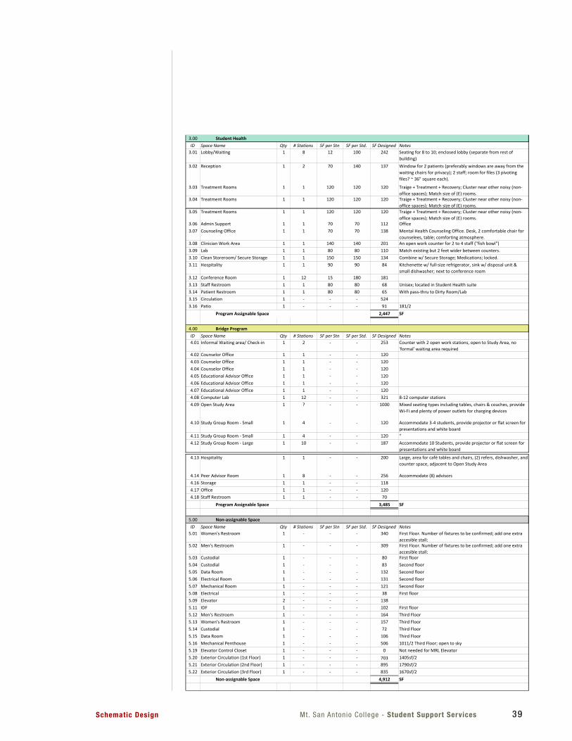
Mt. San Antonio Col lege - Student Support ServicesSchematic Design 39
Mt. SAC - Student Support Services Preliminary Space Program 10/31/12
3.05 Treatment Rooms 1 1 120 120 120 Traige + Treatment + Recovery; Cluster near other noisy (non-office spaces); Match size of (E) rooms.
3.06 Admin Support 1 1 70 70 112 Office3.07 Counseling Office 1 1 70 70 138 Mental Health Counseling Office. Desk, 2 comfortable chair for
counselees, table; comforting atmosphere.3.08 Clinician Work Area 1 1 140 140 201 An open work counter for 2 to 4 staff ("fish bowl")3.09 Lab 1 1 80 80 110 Match existing but 2 feet wider between counters.3.10 Clean Storeroom/ Secure Storage 1 1 150 150 134 Combine w/ Secure Storage; Medications; locked.3.11 Hospitality 1 1 90 90 84 Kitchenette w/ full-size refrigerator, sink w/ disposal unit &
small dishwasher; next to conference room3.12 Conference Room 1 12 15 180 1813.13 Staff Restroom 1 1 80 80 68 Unisex; located in Student Health suite3.14 Patient Restroom 1 1 80 80 65 With pass-thru to Dirty Room/Lab3.15 Circulation 1 - - - 5243.16 Patio 1 - - - 91 181/2
2,447 SF
4.00ID Space Name Qty # Stations SF per Stn SF per Std. SF Designed Notes4.01 Informal Waiting area/ Check-in 1 2 - - 253 Counter with 2 open work stations, open to Study Area, no
'formal' waiting area required4.02 Counselor Office 1 1 - - 1204.03 Counselor Office 1 1 - - 1204.04 Counselor Office 1 1 - - 1204.05 Educational Advisor Office 1 1 - - 1204.06 Educational Advisor Office 1 1 - - 1204.07 Educational Advisor Office 1 1 - - 1204.08 Computer Lab 1 12 - - 321 8-12 computer stations4.09 Open Study Area 1 ? - - 1000 Mixed seating types including tables, chairs & couches, provide
Wi-Fi and plenty of power outlets for charging devices
4.10 Study Group Room - Small 1 4 - - 120 Accommodate 3-4 students, provide projector or flat screen for presentations and white board
4.11 Study Group Room - Small 1 4 - - 120 "4.12 Study Group Room - Large 1 10 - - 187 Accommodate 10 Students, provide projector or flat screen for
presentations and white board
Program Assignable Space
Bridge Program
3
Mt. SAC - Student Support Services Preliminary Space Program 10/31/12
4.13 Hospitality 1 1 - - 200 Large, area for café tables and chairs, (2) refers, dishwasher, and counter space, adjacent to Open Study Area
4.14 Peer Advisor Room 1 8 - - 256 Accommodate (8) advisors4.16 Storage 1 1 - - 1184.17 Office 1 1 - - 1204.18 Staff Restroom 1 1 - - 70
3,485 SF
5.00ID Space Name Qty # Stations SF per Stn SF per Std. SF Designed Notes
5.01 Women's Restroom 1 - - - 340 First Floor. Number of fixtures to be confirmed; add one extra accesible stall;
5.02 Men's Restroom 1 - - - 309 First Floor. Number of fixtures to be confirmed; add one extra accesible stall;
5.03 Custodial 1 - - - 80 First floor5.04 Custodial 1 - - - 83 Second floor5.05 Data Room 1 - - - 132 Second floor5.06 Electrical Room 1 - - - 131 Second floor5.07 Mechanical Room 1 - - - 121 Second floor5.08 Electrical 1 - - - 38 First floor5.09 Elevator 2 - - - 1385.11 IDF 1 - - - 102 First floor5.12 Men's Restroom 1 - - - 164 Third Floor5.13 Women's Restroom 1 - - - 157 Third Floor5.14 Custodial 1 - - - 72 Third Floor5.15 Data Room 1 - - - 106 Third Floor5.16 Mechanical Penthouse 1 - - - 506 1011/2 Third Floor; open to sky5.19 Elevator Control Closet 1 - - - 0 Not needed for MRL Elevator5.20 Exterior Circulation (1st Floor) 1 - - - 703 1405sf/25.21 Exterior Circulation (2nd Floor) 1 - - - 895 1790sf/25.22 Exterior Circulation (3rd Floor) 1 - - - 835 1670sf/2
4,912 SF
6.00ID Space Name Qty # Stations SF per Stn SF per Std. SF Designed Notes
Flexible Program Space (3rd Floor)
Non-assignable Space
Non-assignable Space
Program Assignable Space
4
Mt. SAC - Student Support Services Preliminary Space Program 10/31/12
2.00ID Space Name Qty # Stations SF per Stn SF per Std. SF Designed Notes
2.01 Study Center 1 20 20 400 468 Quiet space, study, laptops, small reception desk, a few computer stations; Need not be in an enclosed space.
2.02 Counseling Office 1 1 70 70 100 Similar to adjunct faculty spaces elsewhere on campus; Similar to small meeting rooms; Also will be used for meetings with vocational rehab counselors and people from outside agencies.
2.03 Counseling Office 1 1 70 70 100 Similar to adjunct faculty spaces elsewhere on campus; Similar to small meeting rooms; Also will be used for meetings with vocational rehab counselors and people from outside agencies.
2.04 Admin Support 1 1 70 70 100 Veterans Services Staff2.05 Student Work Room/
Reception/ Waiting1 4 50 200 367 Alcove/Work/Study; combined w/ Reception/Waiting; L-shaped
counter; Students will fill out certification forms for benefits. This can be an extension of the reception counter; Small copier; storage; form slots near/behind staff.
2.06 Peer Mentoring 1 20 12 240 503 Noisier, casual space; couch, socializing; Area leading to outside patio (see Rio Hondo) but maybe secure to keep others out; Needs to be in an enclosed space; Adjacent to the Hospitality space.
2.07 Hospitality 1 1 90 90 80 Next to Peer Monitoring; Kitchenette w/ full-size refrigerator, sink w/ disposal unit & small dishwasher; next to conference room
1,718 SF
3.00ID Space Name Qty # Stations SF per Stn SF per Std. SF Designed Notes
3.01 Lobby/Waiting 1 8 12 100 242 Seating for 8 to 10; enclosed lobby (separate from rest of building)
3.02 Reception 1 2 70 140 137 Window for 2 patients (preferably windows are away from the waiting chairs for privacy); 2 staff; room for files (3 pivoting files? ~ 36" square each).
3.03 Treatment Rooms 1 1 120 120 120 Traige + Treatment + Recovery; Cluster near other noisy (non-office spaces); Match size of (E) rooms.
3.04 Treatment Rooms 1 1 120 120 120 Traige + Treatment + Recovery; Cluster near other noisy (non-office spaces); Match size of (E) rooms.
Veterans Resource Center
Student Health
Program Assignable Space
2
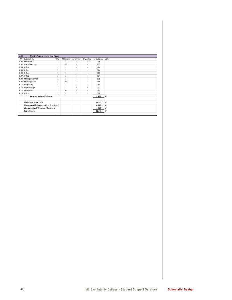
Mt. San Antonio Col lege - Student Support Services Schematic Design40
Mt. SAC - Student Support Services Preliminary Space Program 10/31/12
6.01 Reception 1 1 - - 1566.02 Open Resource 1 30 - - 8176.04 Office 1 1 - - 1246.05 Office 1 1 - - 1246.06 Office 1 1 - - 1216.07 Office 1 1 - - 1246.08 Manager's Office 1 1 - - 1686.09 Meeting Room 1 20 - - 1686.10 Hospitality 1 1 - - 1836.11 Copy/Storage 1 1 - - 1026.12 Circulation 1 0 - - 1706.13 Office 1 2 - - 180
2,437 SF
Assignable Space Total 14,547 SFNon-assignable Space (as identified above) 4,912 SFAllowance Wall Thickness, Shafts, etc 1,226 SFProject Space 20,685 SF
Program Assignable Space
5
Mt. SAC - Student Support Services Preliminary Space Program 10/31/12
4.13 Hospitality 1 1 - - 200 Large, area for café tables and chairs, (2) refers, dishwasher, and counter space, adjacent to Open Study Area
4.14 Peer Advisor Room 1 8 - - 256 Accommodate (8) advisors4.16 Storage 1 1 - - 1184.17 Office 1 1 - - 1204.18 Staff Restroom 1 1 - - 70
3,485 SF
5.00ID Space Name Qty # Stations SF per Stn SF per Std. SF Designed Notes
5.01 Women's Restroom 1 - - - 340 First Floor. Number of fixtures to be confirmed; add one extra accesible stall;
5.02 Men's Restroom 1 - - - 309 First Floor. Number of fixtures to be confirmed; add one extra accesible stall;
5.03 Custodial 1 - - - 80 First floor5.04 Custodial 1 - - - 83 Second floor5.05 Data Room 1 - - - 132 Second floor5.06 Electrical Room 1 - - - 131 Second floor5.07 Mechanical Room 1 - - - 121 Second floor5.08 Electrical 1 - - - 38 First floor5.09 Elevator 2 - - - 1385.11 IDF 1 - - - 102 First floor5.12 Men's Restroom 1 - - - 164 Third Floor5.13 Women's Restroom 1 - - - 157 Third Floor5.14 Custodial 1 - - - 72 Third Floor5.15 Data Room 1 - - - 106 Third Floor5.16 Mechanical Penthouse 1 - - - 506 1011/2 Third Floor; open to sky5.19 Elevator Control Closet 1 - - - 0 Not needed for MRL Elevator5.20 Exterior Circulation (1st Floor) 1 - - - 703 1405sf/25.21 Exterior Circulation (2nd Floor) 1 - - - 895 1790sf/25.22 Exterior Circulation (3rd Floor) 1 - - - 835 1670sf/2
4,912 SF
6.00ID Space Name Qty # Stations SF per Stn SF per Std. SF Designed Notes
Flexible Program Space (3rd Floor)
Non-assignable Space
Non-assignable Space
Program Assignable Space
4
Mt. San AntonioCol lege - Student Support ServicesSchematic Design 41
Code Analysis
4.1 CODE ANALYSIS4.2 EXITING DIAGRAM4.3 PLUMBING FIXTURE CALCULATION
4
1. General Project Information: a. Construction Type II-B (non-rated); no fire-proofing required
b. Occupancy Type: A3 (to achieve non-separated occupancies, see item #3)
c. Fire sprinklers throughout
d. Proposed building height: 40’-6”
e. Proposed building area (per floor):
a. First Floor: 8,478 sf
b. Second Floor: 7,960 sf
c. Third Floor: 6,448 sf
d. Total: 22,886 sf
f. Proposed building occupants (per floor):
a. First Floor: 188 occ
b. Second Floor: 217 occ
c. Third Floor: 102 occ
d. Total: 507 occ
g. Proposed number of stories: 3
2. Allowable Areas, Stories, and Heights (Table 503): a. Per Table 503, the following is allowed (A3 Occupancy):
1. 2 stories
2. 9,500 SF per floor
3. 55’
b. Allowable Area Increases:
1. 3 stories (per 504.2)
2. 9,500 SF per floor
3. 75’ (per 504.2)
4.1 CODE ANALYSIS AND EXITING DIAGRAMS
Mt. San Antonio Col lege - Studenet Support Services Schematic Design4242
3. Incidental Accessary Occupancies (Table 508.2.5): a. Boiler Rooms: 1-hr
b. Mechanical Rooms: 1-hr
c. Storage Rooms >100 SF: 1-hr
4. Non-Separated Occupancies (CBC 508.3): a. Use A3 occupancy throughout building (in lieu of a mix of A3 and B)
b. No separation required between occupancies
5. Exterior Wall Separation Distance (Table 602): a. Current separation distance between new building and existing 9B = 15’
b. Assumed property line will be 5’ from the face of the new building
(and 10’ from the face of 9B)
c. Based on Table 602, the north wall of the new building shall be 1-hr rated
with non-protected openings limited to 25% of the wall area
(per Table 705.8).
d. The existing wall of 9B does not require any protection.
6. Occupant Load Factors (Table 1004.1.1): a. Business Areas: 100 SF/occ
b. Classrooms: 20 SF/occ
c. Storage: 300 SF/occ
d. Assembly: 15 SF/occ
7. Area of Refuge (CBC 1007.6): a. Not required per CBC 1007.6, exception #1
8. Exterior Area for Assisted Rescue (CBC 1007.7): a. 1-hr rated wall behind 30x48 wheelchair area, 10’ long.
9. Two Exit Access (CBC 1015.2.1 and CBC 1016): a. Separate exits by 1/3 the building floor diagonal (okay)
10. Means of Egress (CBC 1016): a. Exit access travel distance: 300’ from remote point to top of riser of
exterior stair (per CBC 1016 exception #2) (okay)
11. Exit Access Travel Distance (Table 1016.1): a. 300’ (with sprinklers)
b. +100’ with exterior egress balcony (per CBC 1016.2)
c. 400’ total distance allowed
Mt. San AntonioCol lege - Student Support ServicesSchematic Design 43
12. Corridor Rating (Table 1018.1): a. 0-hrs (with sprinklers)
13. Dead Ends (CBC 1018.4): a. 20’ maximum in group B building (per CBC 1017.3 exception #2)
14. Egress Balconies (CBC Section 1019) a. 0-hr rating (considered to be non-rated corridors)
15. Required Number of Exits Per Floor (CBC 1021): a. 1-500 occupants = two exits (per table 1021.1) (okay)
16. Required Rated Enclosures: a. Duct Shafts (CBC 708.4): 1-hr
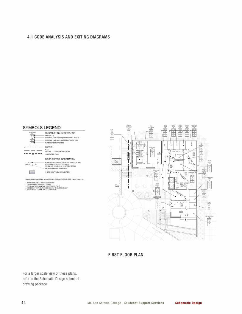
Mt. San Antonio Col lege - Studenet Support Services Schematic Design44
UP
UP
DN
UP
FEC
FEC
FEC
FEC
FEC
FEC
FEC
FEC
FEC
FEC
FEC
FEC
FEC
FEC
721 SF
CLASSROOM104
1
20
37
143 SF
WORKROOM
108
1
100
2
111 SF
FACULTYOFFICE
106
1
100
2
111 SF
FACULTYOFFICE
107
1
100
2
113 SF
FACULTYOFFICE
105
1
100
2
239 SF
MEDIA TECHSUPPORT
111
1
100
3
312 SF
MENSRESTROOM
102
0
0
0
340 SF
WOMENSRESTROOM
101
0
0
080 SF
CUST.103
1
300
1
186 SF
CONFERENCE110
1
15
13
282 SF
ENTRY109
0
0
0
98 SF
IDF112
1
300
1
613 SF
STUDYCENTER
115
1
20
31
192 SF
TECHSUPPORT
114
1
100
2851 SF
COMPUTER LAB116
1
20
43
467 SF
STUDYCENTER
119
1
20
25
95 SF
COUNSELINGOFFICE
121
1
100
1
95 SF
COUNSELINGOFFICE
122
1
100
1
96 SF
ADMINSUPPORT
123
1
100
1
365 SF
STUDENT WORKRM/ RECEPTION/
WAITING120
1
15
26
577 SF
PEER MENTORING124
1
15
39
8872"
13 36"
7472"
20 72"20 36
"
ASSU
MM
EDPR
OP
LIN
E
11' - 1 1/4"
(E)BLDG
(E)BLDG
1-H
R1-
HR
1-HR RATINGAT ELEVHOISTWAY
3636"
44 72"
37 36"
3643"
TRAVELDIST
=88'
TRAVEL DIST = 53'
TRAVEL DIST = 57'
667 SF
CLASSROOM220
1
20
34
1834 SF
OPEN STUDY201
2
20
92
121 SF
SMALL STUDY210
1
15
8
120 SF
SMALL STUDY211
1
15
8
118 SF
COUNSELING212
1
100
2
118 SF
OFFICE213
1
100
2
185 SF
LARGE STUDY202
1
15
13
118 SF
OFFICE203
1
100
2
118 SF
OFFICE204
1
100
2
200 SF
HOSPITALITY205
1
100
2
70 SF
STAFFRRM.214
0
0
0
118 SF
STOR206
1
300
1
120 SF
COUNSELING207
1
100
2
120 SF
COUNSELING208
1
100
2
120 SF
ED. ADVISOR209
1
100
2
133 SF
DATA217
1
300
1
105 SF
MECH218
1
300
1
125 SF
ELEC216
1
300
1
83 SF
CUST.215
1
300
1
119 SF
TREATMENT224
1
100
2
67 SF
PATIENT RRM230
0
0
0
119 SF
TREATMENT225
1
100
2
119 SF
TREATMENT226
1
100
2
242 SF
LOBBY/ WAITING232
1
15
17
103 SF
LAB229
1
100
2
524 SF
HALL228
0
0
0
110 SF
ADMINSUPPORT
221
1
100
2
132 SF
CLEAN STOR./SECURE STOR.
227
1
300
1
66 SF
STAFF RRM.222
0
0
0
82 SF
HOSPITALITY233
1
100
1
181 SF
CONFERENCE234
1
15
13
138 SF
COUNSELOROFFICE
223
1
100
2
340 SF
CLINICIAN WORK231
1
100
4
1-HRSHAFT
ASSU
MM
EDPR
OP
LIN
E
11' - 1 1/4"
(E)BLDG
(E)BLDG
1-H
R1-
HR
1-HR RATINGAT ELEVHOISTWAY
69 72"
69 72"
3436"
59180"
59 72"
2436"
24 36"
TRAV
EL D
IST
= 93
'
TRAVEL DIST = 90'
85 SF
DATA304
1
300
1
69 SF
CUST303
1
300
1
183 SF
MENSRRM301
0
0
0
164 SF
WOMENSRRM302
0
0
0
168 SF
MANAGERSOFFICE
308
1
100
2
121 SF
OFFICE315
1
100
2
156 SF
RECEPTION306
1
15
11
817 SF
OPENRESOURCE
307
1
20
41
124 SF
OFFICE316
1
100
2
124 SF
OFFICE309
1
100
2
124 SF
OFFICE310
1
100
2
180 SF
OFFICE317
1
100
2
388 SF
MEETING ROOM314
1
15
26
97 SF
COPY/ STOR.311
1
100
2
170 SF
HALL312
0
0
0
183 SF
HOSPITALITY313
1
100
2
1-HR RATINGAT ELEVHOISTWAY
AREA OFRESCUEASSISTANCE
1-HR WALL
CLERESTORYOPEN TO BELOW
MECHANICAL WELLOPEN TO ABOVE
ROOF
ROOF
LINE OF ROOFOVERHANGABOVE
2736"
27 36"
28 72"
28 72"
6' - 2"
6' - 0"
TRAVEL DIST = 59'
TRAV
ELD
IST
=85
'
ROOM EXITING INFORMATIONAREA (SQ FT)OCCUPANT LOAD FACTOR (REFER TO TABLE 1004.1.1)OCCUPANT LOAD (AREA DIVIDED BY LOAD FACTOR)
DOOR EXITING INFORMATIONNUMBER OF OCCUPANTS EXITING THRU DOOR OPENING(REQ'D. WIDTH = # OF OCCUPANTS X 0.232" MIN. CLR. REQUIRED AT ACCESSIBLE DOORS)PROVIDED EXIT WIDTH (IN INCHES)
ROOM NAME101
150 SF
# Exit
OL
OLF
SYMBOLS LEGEND
MAXIMUM FLOOR AREA ALLOWANCES PER OCCUPANT (PER TABLE 1004.1.1):
1. BUSINESS AREA: 100 SF/OCCUPANT2. CLASSROOM: 20 SF/OCCUPANT3. STORAGE/MECHANCIAL: 300 SF/OCCUPANT4. ASSEMBLY WITHOUT FIXED SEATS: 15 SF/OCCUPANT5. TREATMENT ROOM: 100 SF/OCCUPANT
EXIT PATHP.O.T.(SEE A0.11 FOR CONTINUATION)
# OCCWIDTH (")
NUMBER OF EXITS PROVIDED
1-HR RATED WALL
1-HR OCCUPANCY SEPARATION
1-HR
PLEASE RECYCLE
Project Title
Agency Approval FILE NO.Consultant Seal
Drawing Title:
Designed:
Drawn:
QAQC
Date:
Project No.
Scale:
Drawing No.
Architect's Seal
IDENTIFICATION STAMPDIV. OF THE STATE ARCHITECT
OFFICE OF REGULATION SERVICES
APPL.
ACDATE
FLS SS
----
DSN
DRW
CHK
010203040506070809
J
H
G
F
E
D
C
B
A
J
H
G
F
E
D
C
B
A
010203040506070809
SM
NOTES
-
T 909 989 9979/ www.hmcarchitects.com3546 Concours Street / Ontario, CA 91764
C:\R
evit
Loca
l File
s\50
1800
4-A
12_c
entra
l_ss
olis
.rvt
11/16/2012 8:49:12 AM
1/16" = 1'-0"
1100 N GRAND STREETWALNUT, CA 91789
Schematic Design
A0.11
EXITING/CODE ANALYSIS
5018004
Student Support Services Building
Mt. San AntonioCollege
10/29/2012
1/16" = 1'-0"
B1FIRST FLOOR - EXITING/CODE ANALYSIS 1/16" = 1'-0"
B3SECOND FLOOR - EXITING/CODE ANALYSIS 1/16" = 1'-0"
B6THIRD FLOOR - EXITING/CODE ANALYSIS
1. MIXED-USE OCCUPANCY GROUPS B AND A3: BUILDING EVALUATED ASNON-SEPARATED OCCUPANCIES BASED UPON MOST RESTRICTIVEGROUP - GROUP A3.
2. EXIT ACCESS TRAVEL DISTANCE (CBC 1016): 300' WITH EXTERIOREGRESS BALCONY INCREASE.
FIRE RESISTANCE RATING REQUIREMENTS FOR BUILDING ELEMENTS
BUILDING ELEMENTPRIMARY STRUCTURE FRAME 0 HRSBEARING WALLS
EXTERIOR 0 HRSINTERIOR 0 HRS
NON BEARING WALLSEXTERIOR 0 HRSINTERIOR 0 HRS
FLOOR CONSTRUCTION 0 HRSROOF CONSTRUCTION 0 HRS *CLASS C ROOF ASSEMBLY MINIMUMCORRIDOR RATING 0 HRSEXTERIOR EXIT BALCONIES 0 HRS
BASED ON 2010 CBC - CONSTRUCTION TYPE II-B
OCCUPANCY GROUP CLASSIFICATION - CHAPTER 3
B OCCUPANCY - OFFICES, CLASSROOMS, COMPUTER LABSA3 OCCUPANCY - CONFERENCE ROOMS, STUDY AREAS/ROOMS
MIXED USE OCCUPANCY - NON SEPARATED OCCUPANCIES - (SECTION 508.3)MOST RESTRICTIVE OCCUPANCY GROUP - A3 OCCUPANCY
ALLOWABLE BUILDING AREA - (CBC TABLE 503)A3 OCCUPANCY - BASE ALLOWABLE AREA = 9,500 S.F. (PER FLOOR)
MAXIMUM STORIES = 3 (INCREASE PER 504.2)MAXIMUM BUILDING HEIGHT = 75' (INCREASE PER 504.2)
BUILDING AREA MODIFICATIONS - CBC SECTION 506 EQUATION 5-1NONE
BUILDING OCCUPANT LOAD:
1. FIRST FLOOR = 323 OCCUPANTS2. SECOND FLOOR = 224 OCCUPANTS3. THIRD FLOOR = 55 OCCUPANTS
TOTAL = 511 OCCUPANTS
nnn
BUILDING AREA CALCULATIONS:
FIRST FLOOR AREA: ENCLOSED: 6,148 SF COVERED WALKWAYS: 1,120 SF FIRST FLOOR TOTAL: 8,478 SF
SECOND FLOOR AREA: ENCLOSED: 7,358 SF EXTERIOR BALCONY/WALKWAY: 1,812 SF SECOND FLOOR TOTAL: 7,960 SF
THIRD FLOOR AREA: ENCLOSED: 3,788 SF EXTERIOR BALCONY/MECHANICAL WELL: 2,660 SF SECOND FLOOR TOTAL: 6,448 SF
GRAND TOTAL: 22,886 SF
No. Description Date
UP
UP
DN
UP
FEC
FEC
FEC
FEC
FEC
FEC
FEC
FEC
FEC
FEC
FEC
FEC
FEC
FEC
721 SF
CLASSROOM104
1
20
37
143 SF
WORKROOM
108
1
100
2
111 SF
FACULTYOFFICE
106
1
100
2
111 SF
FACULTYOFFICE
107
1
100
2
113 SF
FACULTYOFFICE
105
1
100
2
239 SF
MEDIA TECHSUPPORT
111
1
100
3
312 SF
MENSRESTROOM
102
0
0
0
340 SF
WOMENSRESTROOM
101
0
0
080 SF
CUST.103
1
300
1
186 SF
CONFERENCE110
1
15
13
282 SF
ENTRY109
0
0
0
98 SF
IDF112
1
300
1
613 SF
STUDYCENTER
115
1
20
31
192 SF
TECHSUPPORT
114
1
100
2851 SF
COMPUTER LAB116
1
20
43
467 SF
STUDYCENTER
119
1
20
25
95 SF
COUNSELINGOFFICE
121
1
100
1
95 SF
COUNSELINGOFFICE
122
1
100
1
96 SF
ADMINSUPPORT
123
1
100
1
365 SF
STUDENT WORKRM/ RECEPTION/
WAITING120
1
15
26
577 SF
PEER MENTORING124
1
15
39
8872"
13 36"
7472"
20 72"20 36
"
ASSU
MM
EDPR
OP
LIN
E
11' - 1 1/4"
(E)BLDG
(E)BLDG
1-H
R1-
HR
1-HR RATINGAT ELEVHOISTWAY
3636"
44 72"
37 36"
3643"
TRAVELDIST
=88'
TRAVEL DIST = 53'
TRAVEL DIST = 57'
667 SF
CLASSROOM220
1
20
34
1834 SF
OPEN STUDY201
2
20
92
121 SF
SMALL STUDY210
1
15
8
120 SF
SMALL STUDY211
1
15
8
118 SF
COUNSELING212
1
100
2
118 SF
OFFICE213
1
100
2
185 SF
LARGE STUDY202
1
15
13
118 SF
OFFICE203
1
100
2
118 SF
OFFICE204
1
100
2
200 SF
HOSPITALITY205
1
100
2
70 SF
STAFFRRM.214
0
0
0
118 SF
STOR206
1
300
1
120 SF
COUNSELING207
1
100
2
120 SF
COUNSELING208
1
100
2
120 SF
ED. ADVISOR209
1
100
2
133 SF
DATA217
1
300
1
105 SF
MECH218
1
300
1
125 SF
ELEC216
1
300
1
83 SF
CUST.215
1
300
1
119 SF
TREATMENT224
1
100
2
67 SF
PATIENT RRM230
0
0
0
119 SF
TREATMENT225
1
100
2
119 SF
TREATMENT226
1
100
2
242 SF
LOBBY/ WAITING232
1
15
17
103 SF
LAB229
1
100
2
524 SF
HALL228
0
0
0
110 SF
ADMINSUPPORT
221
1
100
2
132 SF
CLEAN STOR./SECURE STOR.
227
1
300
1
66 SF
STAFF RRM.222
0
0
0
82 SF
HOSPITALITY233
1
100
1
181 SF
CONFERENCE234
1
15
13
138 SF
COUNSELOROFFICE
223
1
100
2
340 SF
CLINICIAN WORK231
1
100
4
1-HRSHAFT
ASSU
MM
EDPR
OP
LIN
E
11' - 1 1/4"
(E)BLDG
(E)BLDG
1-H
R1-
HR
1-HR RATINGAT ELEVHOISTWAY
69 72"
69 72"
3436"
59180"
59 72"
2436"
24 36"
TRAV
EL D
IST
= 93
'
TRAVEL DIST = 90'
85 SF
DATA304
1
300
1
69 SF
CUST303
1
300
1
183 SF
MENSRRM301
0
0
0
164 SF
WOMENSRRM302
0
0
0
168 SF
MANAGERSOFFICE
308
1
100
2
121 SF
OFFICE315
1
100
2
156 SF
RECEPTION306
1
15
11
817 SF
OPENRESOURCE
307
1
20
41
124 SF
OFFICE316
1
100
2
124 SF
OFFICE309
1
100
2
124 SF
OFFICE310
1
100
2
180 SF
OFFICE317
1
100
2
388 SF
MEETING ROOM314
1
15
26
97 SF
COPY/ STOR.311
1
100
2
170 SF
HALL312
0
0
0
183 SF
HOSPITALITY313
1
100
2
1-HR RATINGAT ELEVHOISTWAY
AREA OFRESCUEASSISTANCE
1-HR WALL
CLERESTORYOPEN TO BELOW
MECHANICAL WELLOPEN TO ABOVE
ROOF
ROOF
LINE OF ROOFOVERHANGABOVE
2736"
27 36"
28 72"
28 72"
6' - 2"
6' - 0"
TRAVEL DIST = 59'
TRAV
ELD
IST
=85
'
ROOM EXITING INFORMATIONAREA (SQ FT)OCCUPANT LOAD FACTOR (REFER TO TABLE 1004.1.1)OCCUPANT LOAD (AREA DIVIDED BY LOAD FACTOR)
DOOR EXITING INFORMATIONNUMBER OF OCCUPANTS EXITING THRU DOOR OPENING(REQ'D. WIDTH = # OF OCCUPANTS X 0.232" MIN. CLR. REQUIRED AT ACCESSIBLE DOORS)PROVIDED EXIT WIDTH (IN INCHES)
ROOM NAME101
150 SF
# Exit
OL
OLF
SYMBOLS LEGEND
MAXIMUM FLOOR AREA ALLOWANCES PER OCCUPANT (PER TABLE 1004.1.1):
1. BUSINESS AREA: 100 SF/OCCUPANT2. CLASSROOM: 20 SF/OCCUPANT3. STORAGE/MECHANCIAL: 300 SF/OCCUPANT4. ASSEMBLY WITHOUT FIXED SEATS: 15 SF/OCCUPANT5. TREATMENT ROOM: 100 SF/OCCUPANT
EXIT PATHP.O.T.(SEE A0.11 FOR CONTINUATION)
# OCCWIDTH (")
NUMBER OF EXITS PROVIDED
1-HR RATED WALL
1-HR OCCUPANCY SEPARATION
1-HR
PLEASE RECYCLE
Project Title
Agency Approval FILE NO.Consultant Seal
Drawing Title:
Designed:
Drawn:
QAQC
Date:
Project No.
Scale:
Drawing No.
Architect's Seal
IDENTIFICATION STAMPDIV. OF THE STATE ARCHITECT
OFFICE OF REGULATION SERVICES
APPL.
ACDATE
FLS SS
----
DSN
DRW
CHK
010203040506070809
J
H
G
F
E
D
C
B
A
J
H
G
F
E
D
C
B
A
010203040506070809
SM
NOTES
-
T 909 989 9979/ www.hmcarchitects.com3546 Concours Street / Ontario, CA 91764
C:\R
evit
Loca
l File
s\50
1800
4-A
12_c
entra
l_ss
olis
.rvt
11/16/2012 8:49:12 AM
1/16" = 1'-0"
1100 N GRAND STREETWALNUT, CA 91789
Schematic Design
A0.11
EXITING/CODE ANALYSIS
5018004
Student Support Services Building
Mt. San AntonioCollege
10/29/2012
1/16" = 1'-0"
B1FIRST FLOOR - EXITING/CODE ANALYSIS 1/16" = 1'-0"
B3SECOND FLOOR - EXITING/CODE ANALYSIS 1/16" = 1'-0"
B6THIRD FLOOR - EXITING/CODE ANALYSIS
1. MIXED-USE OCCUPANCY GROUPS B AND A3: BUILDING EVALUATED ASNON-SEPARATED OCCUPANCIES BASED UPON MOST RESTRICTIVEGROUP - GROUP A3.
2. EXIT ACCESS TRAVEL DISTANCE (CBC 1016): 300' WITH EXTERIOREGRESS BALCONY INCREASE.
FIRE RESISTANCE RATING REQUIREMENTS FOR BUILDING ELEMENTS
BUILDING ELEMENTPRIMARY STRUCTURE FRAME 0 HRSBEARING WALLS
EXTERIOR 0 HRSINTERIOR 0 HRS
NON BEARING WALLSEXTERIOR 0 HRSINTERIOR 0 HRS
FLOOR CONSTRUCTION 0 HRSROOF CONSTRUCTION 0 HRS *CLASS C ROOF ASSEMBLY MINIMUMCORRIDOR RATING 0 HRSEXTERIOR EXIT BALCONIES 0 HRS
BASED ON 2010 CBC - CONSTRUCTION TYPE II-B
OCCUPANCY GROUP CLASSIFICATION - CHAPTER 3
B OCCUPANCY - OFFICES, CLASSROOMS, COMPUTER LABSA3 OCCUPANCY - CONFERENCE ROOMS, STUDY AREAS/ROOMS
MIXED USE OCCUPANCY - NON SEPARATED OCCUPANCIES - (SECTION 508.3)MOST RESTRICTIVE OCCUPANCY GROUP - A3 OCCUPANCY
ALLOWABLE BUILDING AREA - (CBC TABLE 503)A3 OCCUPANCY - BASE ALLOWABLE AREA = 9,500 S.F. (PER FLOOR)
MAXIMUM STORIES = 3 (INCREASE PER 504.2)MAXIMUM BUILDING HEIGHT = 75' (INCREASE PER 504.2)
BUILDING AREA MODIFICATIONS - CBC SECTION 506 EQUATION 5-1NONE
BUILDING OCCUPANT LOAD:
1. FIRST FLOOR = 323 OCCUPANTS2. SECOND FLOOR = 224 OCCUPANTS3. THIRD FLOOR = 55 OCCUPANTS
TOTAL = 511 OCCUPANTS
nnn
BUILDING AREA CALCULATIONS:
FIRST FLOOR AREA: ENCLOSED: 6,148 SF COVERED WALKWAYS: 1,120 SF FIRST FLOOR TOTAL: 8,478 SF
SECOND FLOOR AREA: ENCLOSED: 7,358 SF EXTERIOR BALCONY/WALKWAY: 1,812 SF SECOND FLOOR TOTAL: 7,960 SF
THIRD FLOOR AREA: ENCLOSED: 3,788 SF EXTERIOR BALCONY/MECHANICAL WELL: 2,660 SF SECOND FLOOR TOTAL: 6,448 SF
GRAND TOTAL: 22,886 SF
No. Description Date
4.1 CODE ANALYSIS AND EXITING DIAGRAMS
FIRST FLOOR PLAN
For a larger scale view of these plans,
refer to the Schematic Design submittal
drawing package
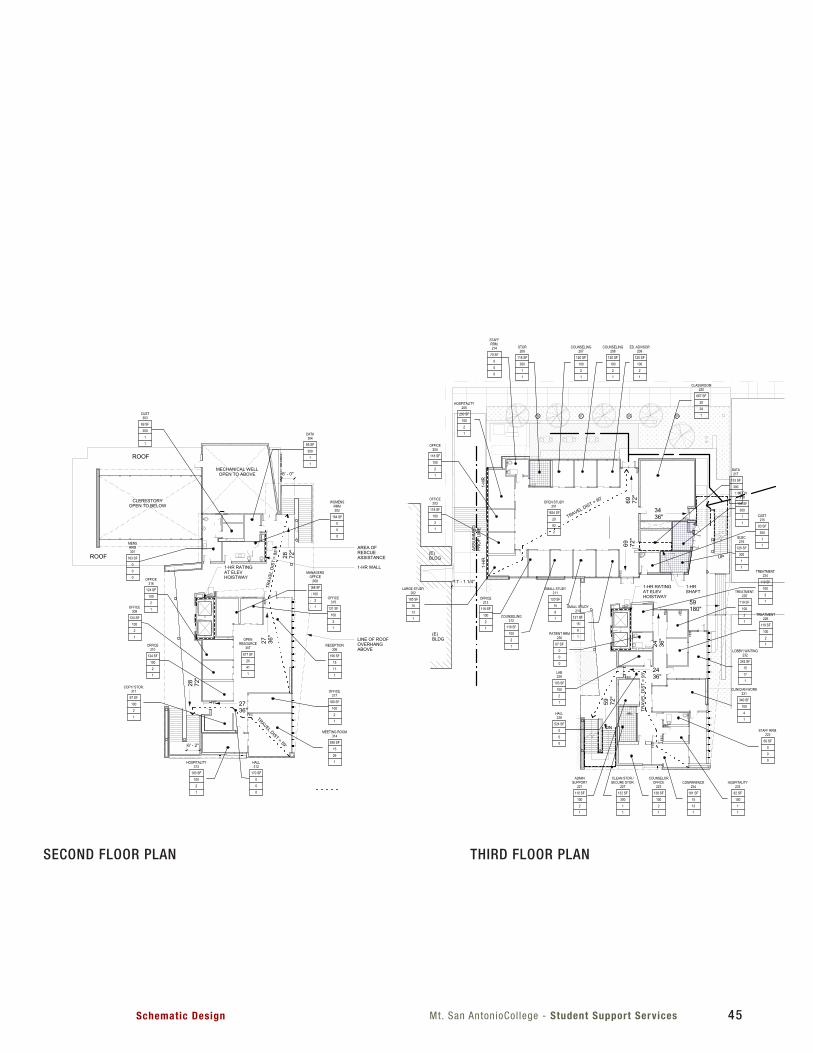
Mt. San AntonioCol lege - Student Support ServicesSchematic Design 45
UP
UP
DN
UP
FEC
FEC
FEC
FEC
FEC
FEC
FEC
FEC
FEC
FEC
FEC
FEC
FEC
FEC
721 SF
CLASSROOM104
1
20
37
143 SF
WORKROOM
108
1
100
2
111 SF
FACULTYOFFICE
106
1
100
2
111 SF
FACULTYOFFICE
107
1
100
2
113 SF
FACULTYOFFICE
105
1
100
2
239 SF
MEDIA TECHSUPPORT
111
1
100
3
312 SF
MENSRESTROOM
102
0
0
0
340 SF
WOMENSRESTROOM
101
0
0
080 SF
CUST.103
1
300
1
186 SF
CONFERENCE110
1
15
13
282 SF
ENTRY109
0
0
0
98 SF
IDF112
1
300
1
613 SF
STUDYCENTER
115
1
20
31
192 SF
TECHSUPPORT
114
1
100
2851 SF
COMPUTER LAB116
1
20
43
467 SF
STUDYCENTER
119
1
20
25
95 SF
COUNSELINGOFFICE
121
1
100
1
95 SF
COUNSELINGOFFICE
122
1
100
1
96 SF
ADMINSUPPORT
123
1
100
1
365 SF
STUDENT WORKRM/ RECEPTION/
WAITING120
1
15
26
577 SF
PEER MENTORING124
1
15
39
8872"
13 36"
7472"
20 72"20 36
"
ASSU
MM
EDPR
OP
LIN
E
11' - 1 1/4"
(E)BLDG
(E)BLDG
1-H
R1-
HR
1-HR RATINGAT ELEVHOISTWAY
3636"
44 72"
37 36"
3643"
TRAVELDIST
=88'
TRAVEL DIST = 53'
TRAVEL DIST = 57'
667 SF
CLASSROOM220
1
20
34
1834 SF
OPEN STUDY201
2
20
92
121 SF
SMALL STUDY210
1
15
8
120 SF
SMALL STUDY211
1
15
8
118 SF
COUNSELING212
1
100
2
118 SF
OFFICE213
1
100
2
185 SF
LARGE STUDY202
1
15
13
118 SF
OFFICE203
1
100
2
118 SF
OFFICE204
1
100
2
200 SF
HOSPITALITY205
1
100
2
70 SF
STAFFRRM.214
0
0
0
118 SF
STOR206
1
300
1
120 SF
COUNSELING207
1
100
2
120 SF
COUNSELING208
1
100
2
120 SF
ED. ADVISOR209
1
100
2
133 SF
DATA217
1
300
1
105 SF
MECH218
1
300
1
125 SF
ELEC216
1
300
1
83 SF
CUST.215
1
300
1
119 SF
TREATMENT224
1
100
2
67 SF
PATIENT RRM230
0
0
0
119 SF
TREATMENT225
1
100
2
119 SF
TREATMENT226
1
100
2
242 SF
LOBBY/ WAITING232
1
15
17
103 SF
LAB229
1
100
2
524 SF
HALL228
0
0
0
110 SF
ADMINSUPPORT
221
1
100
2
132 SF
CLEAN STOR./SECURE STOR.
227
1
300
1
66 SF
STAFF RRM.222
0
0
0
82 SF
HOSPITALITY233
1
100
1
181 SF
CONFERENCE234
1
15
13
138 SF
COUNSELOROFFICE
223
1
100
2
340 SF
CLINICIAN WORK231
1
100
4
1-HRSHAFT
ASSU
MM
EDPR
OP
LIN
E
11' - 1 1/4"
(E)BLDG
(E)BLDG
1-H
R1-
HR
1-HR RATINGAT ELEVHOISTWAY
69 72"
69 72"
3436"
59180"
59 72"
2436"
24 36"
TRAV
EL D
IST
= 93
'
TRAVEL DIST = 90'
85 SF
DATA304
1
300
1
69 SF
CUST303
1
300
1
183 SF
MENSRRM301
0
0
0
164 SF
WOMENSRRM302
0
0
0
168 SF
MANAGERSOFFICE
308
1
100
2
121 SF
OFFICE315
1
100
2
156 SF
RECEPTION306
1
15
11
817 SF
OPENRESOURCE
307
1
20
41
124 SF
OFFICE316
1
100
2
124 SF
OFFICE309
1
100
2
124 SF
OFFICE310
1
100
2
180 SF
OFFICE317
1
100
2
388 SF
MEETING ROOM314
1
15
26
97 SF
COPY/ STOR.311
1
100
2
170 SF
HALL312
0
0
0
183 SF
HOSPITALITY313
1
100
2
1-HR RATINGAT ELEVHOISTWAY
AREA OFRESCUEASSISTANCE
1-HR WALL
CLERESTORYOPEN TO BELOW
MECHANICAL WELLOPEN TO ABOVE
ROOF
ROOF
LINE OF ROOFOVERHANGABOVE
2736"
27 36"
28 72"
28 72"
6' - 2"
6' - 0"
TRAVEL DIST = 59'
TRAV
ELD
IST
=85
'
ROOM EXITING INFORMATIONAREA (SQ FT)OCCUPANT LOAD FACTOR (REFER TO TABLE 1004.1.1)OCCUPANT LOAD (AREA DIVIDED BY LOAD FACTOR)
DOOR EXITING INFORMATIONNUMBER OF OCCUPANTS EXITING THRU DOOR OPENING(REQ'D. WIDTH = # OF OCCUPANTS X 0.232" MIN. CLR. REQUIRED AT ACCESSIBLE DOORS)PROVIDED EXIT WIDTH (IN INCHES)
ROOM NAME101
150 SF
# Exit
OL
OLF
SYMBOLS LEGEND
MAXIMUM FLOOR AREA ALLOWANCES PER OCCUPANT (PER TABLE 1004.1.1):
1. BUSINESS AREA: 100 SF/OCCUPANT2. CLASSROOM: 20 SF/OCCUPANT3. STORAGE/MECHANCIAL: 300 SF/OCCUPANT4. ASSEMBLY WITHOUT FIXED SEATS: 15 SF/OCCUPANT5. TREATMENT ROOM: 100 SF/OCCUPANT
EXIT PATHP.O.T.(SEE A0.11 FOR CONTINUATION)
# OCCWIDTH (")
NUMBER OF EXITS PROVIDED
1-HR RATED WALL
1-HR OCCUPANCY SEPARATION
1-HR
PLEASE RECYCLE
Project Title
Agency Approval FILE NO.Consultant Seal
Drawing Title:
Designed:
Drawn:
QAQC
Date:
Project No.
Scale:
Drawing No.
Architect's Seal
IDENTIFICATION STAMPDIV. OF THE STATE ARCHITECT
OFFICE OF REGULATION SERVICES
APPL.
ACDATE
FLS SS
----
DSN
DRW
CHK
010203040506070809
J
H
G
F
E
D
C
B
A
J
H
G
F
E
D
C
B
A
010203040506070809
SM
NOTES
-
T 909 989 9979/ www.hmcarchitects.com3546 Concours Street / Ontario, CA 91764
C:\R
evit
Loca
l File
s\50
1800
4-A
12_c
entra
l_ss
olis
.rvt
11/16/2012 8:49:12 AM
1/16" = 1'-0"
1100 N GRAND STREETWALNUT, CA 91789
Schematic Design
A0.11
EXITING/CODE ANALYSIS
5018004
Student Support Services Building
Mt. San AntonioCollege
10/29/2012
1/16" = 1'-0"
B1FIRST FLOOR - EXITING/CODE ANALYSIS 1/16" = 1'-0"
B3SECOND FLOOR - EXITING/CODE ANALYSIS 1/16" = 1'-0"
B6THIRD FLOOR - EXITING/CODE ANALYSIS
1. MIXED-USE OCCUPANCY GROUPS B AND A3: BUILDING EVALUATED ASNON-SEPARATED OCCUPANCIES BASED UPON MOST RESTRICTIVEGROUP - GROUP A3.
2. EXIT ACCESS TRAVEL DISTANCE (CBC 1016): 300' WITH EXTERIOREGRESS BALCONY INCREASE.
FIRE RESISTANCE RATING REQUIREMENTS FOR BUILDING ELEMENTS
BUILDING ELEMENTPRIMARY STRUCTURE FRAME 0 HRSBEARING WALLS
EXTERIOR 0 HRSINTERIOR 0 HRS
NON BEARING WALLSEXTERIOR 0 HRSINTERIOR 0 HRS
FLOOR CONSTRUCTION 0 HRSROOF CONSTRUCTION 0 HRS *CLASS C ROOF ASSEMBLY MINIMUMCORRIDOR RATING 0 HRSEXTERIOR EXIT BALCONIES 0 HRS
BASED ON 2010 CBC - CONSTRUCTION TYPE II-B
OCCUPANCY GROUP CLASSIFICATION - CHAPTER 3
B OCCUPANCY - OFFICES, CLASSROOMS, COMPUTER LABSA3 OCCUPANCY - CONFERENCE ROOMS, STUDY AREAS/ROOMS
MIXED USE OCCUPANCY - NON SEPARATED OCCUPANCIES - (SECTION 508.3)MOST RESTRICTIVE OCCUPANCY GROUP - A3 OCCUPANCY
ALLOWABLE BUILDING AREA - (CBC TABLE 503)A3 OCCUPANCY - BASE ALLOWABLE AREA = 9,500 S.F. (PER FLOOR)
MAXIMUM STORIES = 3 (INCREASE PER 504.2)MAXIMUM BUILDING HEIGHT = 75' (INCREASE PER 504.2)
BUILDING AREA MODIFICATIONS - CBC SECTION 506 EQUATION 5-1NONE
BUILDING OCCUPANT LOAD:
1. FIRST FLOOR = 323 OCCUPANTS2. SECOND FLOOR = 224 OCCUPANTS3. THIRD FLOOR = 55 OCCUPANTS
TOTAL = 511 OCCUPANTS
nnn
BUILDING AREA CALCULATIONS:
FIRST FLOOR AREA: ENCLOSED: 6,148 SF COVERED WALKWAYS: 1,120 SF FIRST FLOOR TOTAL: 8,478 SF
SECOND FLOOR AREA: ENCLOSED: 7,358 SF EXTERIOR BALCONY/WALKWAY: 1,812 SF SECOND FLOOR TOTAL: 7,960 SF
THIRD FLOOR AREA: ENCLOSED: 3,788 SF EXTERIOR BALCONY/MECHANICAL WELL: 2,660 SF SECOND FLOOR TOTAL: 6,448 SF
GRAND TOTAL: 22,886 SF
No. Description Date
UP
UP
DN
UP
FEC
FEC
FEC
FEC
FEC
FEC
FEC
FEC
FEC
FEC
FEC
FEC
FEC
FEC
721 SF
CLASSROOM104
1
20
37
143 SF
WORKROOM
108
1
100
2
111 SF
FACULTYOFFICE
106
1
100
2
111 SF
FACULTYOFFICE
107
1
100
2
113 SF
FACULTYOFFICE
105
1
100
2
239 SF
MEDIA TECHSUPPORT
111
1
100
3
312 SF
MENSRESTROOM
102
0
0
0
340 SF
WOMENSRESTROOM
101
0
0
080 SF
CUST.103
1
300
1
186 SF
CONFERENCE110
1
15
13
282 SF
ENTRY109
0
0
0
98 SF
IDF112
1
300
1
613 SF
STUDYCENTER
115
1
20
31
192 SF
TECHSUPPORT
114
1
100
2851 SF
COMPUTER LAB116
1
20
43
467 SF
STUDYCENTER
119
1
20
25
95 SF
COUNSELINGOFFICE
121
1
100
1
95 SF
COUNSELINGOFFICE
122
1
100
1
96 SF
ADMINSUPPORT
123
1
100
1
365 SF
STUDENT WORKRM/ RECEPTION/
WAITING120
1
15
26
577 SF
PEER MENTORING124
1
15
39
8872"
13 36"
7472"
20 72"20 36
"
ASSU
MM
EDPR
OP
LIN
E
11' - 1 1/4"
(E)BLDG
(E)BLDG
1-H
R1-
HR
1-HR RATINGAT ELEVHOISTWAY
3636"
44 72"
37 36"
3643"
TRAVELDIST
=88'
TRAVEL DIST = 53'
TRAVEL DIST = 57'
667 SF
CLASSROOM220
1
20
34
1834 SF
OPEN STUDY201
2
20
92
121 SF
SMALL STUDY210
1
15
8
120 SF
SMALL STUDY211
1
15
8
118 SF
COUNSELING212
1
100
2
118 SF
OFFICE213
1
100
2
185 SF
LARGE STUDY202
1
15
13
118 SF
OFFICE203
1
100
2
118 SF
OFFICE204
1
100
2
200 SF
HOSPITALITY205
1
100
2
70 SF
STAFFRRM.214
0
0
0
118 SF
STOR206
1
300
1
120 SF
COUNSELING207
1
100
2
120 SF
COUNSELING208
1
100
2
120 SF
ED. ADVISOR209
1
100
2
133 SF
DATA217
1
300
1
105 SF
MECH218
1
300
1
125 SF
ELEC216
1
300
1
83 SF
CUST.215
1
300
1
119 SF
TREATMENT224
1
100
2
67 SF
PATIENT RRM230
0
0
0
119 SF
TREATMENT225
1
100
2
119 SF
TREATMENT226
1
100
2
242 SF
LOBBY/ WAITING232
1
15
17
103 SF
LAB229
1
100
2
524 SF
HALL228
0
0
0
110 SF
ADMINSUPPORT
221
1
100
2
132 SF
CLEAN STOR./SECURE STOR.
227
1
300
1
66 SF
STAFF RRM.222
0
0
0
82 SF
HOSPITALITY233
1
100
1
181 SF
CONFERENCE234
1
15
13
138 SF
COUNSELOROFFICE
223
1
100
2
340 SF
CLINICIAN WORK231
1
100
4
1-HRSHAFT
ASSU
MM
EDPR
OP
LIN
E
11' - 1 1/4"
(E)BLDG
(E)BLDG
1-H
R1-
HR
1-HR RATINGAT ELEVHOISTWAY
69 72"
69 72"
3436"
59180"
59 72"
2436"
24 36"
TRAV
EL D
IST
= 93
'
TRAVEL DIST = 90'
85 SF
DATA304
1
300
1
69 SF
CUST303
1
300
1
183 SF
MENSRRM301
0
0
0
164 SF
WOMENSRRM302
0
0
0
168 SF
MANAGERSOFFICE
308
1
100
2
121 SF
OFFICE315
1
100
2
156 SF
RECEPTION306
1
15
11
817 SF
OPENRESOURCE
307
1
20
41
124 SF
OFFICE316
1
100
2
124 SF
OFFICE309
1
100
2
124 SF
OFFICE310
1
100
2
180 SF
OFFICE317
1
100
2
388 SF
MEETING ROOM314
1
15
26
97 SF
COPY/ STOR.311
1
100
2
170 SF
HALL312
0
0
0
183 SF
HOSPITALITY313
1
100
2
1-HR RATINGAT ELEVHOISTWAY
AREA OFRESCUEASSISTANCE
1-HR WALL
CLERESTORYOPEN TO BELOW
MECHANICAL WELLOPEN TO ABOVE
ROOF
ROOF
LINE OF ROOFOVERHANGABOVE
2736"
27 36"
28 72"
28 72"
6' - 2"
6' - 0"
TRAVEL DIST = 59'
TRAV
ELD
IST
=85
'
ROOM EXITING INFORMATIONAREA (SQ FT)OCCUPANT LOAD FACTOR (REFER TO TABLE 1004.1.1)OCCUPANT LOAD (AREA DIVIDED BY LOAD FACTOR)
DOOR EXITING INFORMATIONNUMBER OF OCCUPANTS EXITING THRU DOOR OPENING(REQ'D. WIDTH = # OF OCCUPANTS X 0.232" MIN. CLR. REQUIRED AT ACCESSIBLE DOORS)PROVIDED EXIT WIDTH (IN INCHES)
ROOM NAME101
150 SF
# Exit
OL
OLF
SYMBOLS LEGEND
MAXIMUM FLOOR AREA ALLOWANCES PER OCCUPANT (PER TABLE 1004.1.1):
1. BUSINESS AREA: 100 SF/OCCUPANT2. CLASSROOM: 20 SF/OCCUPANT3. STORAGE/MECHANCIAL: 300 SF/OCCUPANT4. ASSEMBLY WITHOUT FIXED SEATS: 15 SF/OCCUPANT5. TREATMENT ROOM: 100 SF/OCCUPANT
EXIT PATHP.O.T.(SEE A0.11 FOR CONTINUATION)
# OCCWIDTH (")
NUMBER OF EXITS PROVIDED
1-HR RATED WALL
1-HR OCCUPANCY SEPARATION
1-HR
PLEASE RECYCLE
Project Title
Agency Approval FILE NO.Consultant Seal
Drawing Title:
Designed:
Drawn:
QAQC
Date:
Project No.
Scale:
Drawing No.
Architect's Seal
IDENTIFICATION STAMPDIV. OF THE STATE ARCHITECT
OFFICE OF REGULATION SERVICES
APPL.
ACDATE
FLS SS
----
DSN
DRW
CHK
010203040506070809
J
H
G
F
E
D
C
B
A
J
H
G
F
E
D
C
B
A
010203040506070809
SM
NOTES
-
T 909 989 9979/ www.hmcarchitects.com3546 Concours Street / Ontario, CA 91764
C:\R
evit
Loca
l File
s\50
1800
4-A
12_c
entra
l_ss
olis
.rvt
11/16/2012 8:49:12 AM
1/16" = 1'-0"
1100 N GRAND STREETWALNUT, CA 91789
Schematic Design
A0.11
EXITING/CODE ANALYSIS
5018004
Student Support Services Building
Mt. San AntonioCollege
10/29/2012
1/16" = 1'-0"
B1FIRST FLOOR - EXITING/CODE ANALYSIS 1/16" = 1'-0"
B3SECOND FLOOR - EXITING/CODE ANALYSIS 1/16" = 1'-0"
B6THIRD FLOOR - EXITING/CODE ANALYSIS
1. MIXED-USE OCCUPANCY GROUPS B AND A3: BUILDING EVALUATED ASNON-SEPARATED OCCUPANCIES BASED UPON MOST RESTRICTIVEGROUP - GROUP A3.
2. EXIT ACCESS TRAVEL DISTANCE (CBC 1016): 300' WITH EXTERIOREGRESS BALCONY INCREASE.
FIRE RESISTANCE RATING REQUIREMENTS FOR BUILDING ELEMENTS
BUILDING ELEMENTPRIMARY STRUCTURE FRAME 0 HRSBEARING WALLS
EXTERIOR 0 HRSINTERIOR 0 HRS
NON BEARING WALLSEXTERIOR 0 HRSINTERIOR 0 HRS
FLOOR CONSTRUCTION 0 HRSROOF CONSTRUCTION 0 HRS *CLASS C ROOF ASSEMBLY MINIMUMCORRIDOR RATING 0 HRSEXTERIOR EXIT BALCONIES 0 HRS
BASED ON 2010 CBC - CONSTRUCTION TYPE II-B
OCCUPANCY GROUP CLASSIFICATION - CHAPTER 3
B OCCUPANCY - OFFICES, CLASSROOMS, COMPUTER LABSA3 OCCUPANCY - CONFERENCE ROOMS, STUDY AREAS/ROOMS
MIXED USE OCCUPANCY - NON SEPARATED OCCUPANCIES - (SECTION 508.3)MOST RESTRICTIVE OCCUPANCY GROUP - A3 OCCUPANCY
ALLOWABLE BUILDING AREA - (CBC TABLE 503)A3 OCCUPANCY - BASE ALLOWABLE AREA = 9,500 S.F. (PER FLOOR)
MAXIMUM STORIES = 3 (INCREASE PER 504.2)MAXIMUM BUILDING HEIGHT = 75' (INCREASE PER 504.2)
BUILDING AREA MODIFICATIONS - CBC SECTION 506 EQUATION 5-1NONE
BUILDING OCCUPANT LOAD:
1. FIRST FLOOR = 323 OCCUPANTS2. SECOND FLOOR = 224 OCCUPANTS3. THIRD FLOOR = 55 OCCUPANTS
TOTAL = 511 OCCUPANTS
nnn
BUILDING AREA CALCULATIONS:
FIRST FLOOR AREA: ENCLOSED: 6,148 SF COVERED WALKWAYS: 1,120 SF FIRST FLOOR TOTAL: 8,478 SF
SECOND FLOOR AREA: ENCLOSED: 7,358 SF EXTERIOR BALCONY/WALKWAY: 1,812 SF SECOND FLOOR TOTAL: 7,960 SF
THIRD FLOOR AREA: ENCLOSED: 3,788 SF EXTERIOR BALCONY/MECHANICAL WELL: 2,660 SF SECOND FLOOR TOTAL: 6,448 SF
GRAND TOTAL: 22,886 SF
No. Description Date
SECOND FLOOR PLAN THIRD FLOOR PLAN

Mt. San Antonio Col lege - Studenet Support Services Schematic Design46
Provided: 3 4 73 3 4 4 0 3
4.3 PLUMBING FIXTURE CALCULATION
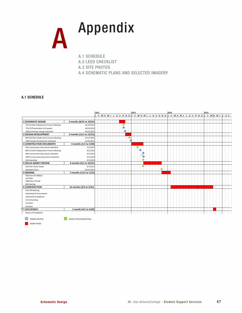
Mt. San AntonioCol lege - Student Support ServicesSchematic Design 47
Appendix
A.1 SCHEDULEA.2 LEED CHECKLISTA.3 SITE PHOTOSA.4 SCHEMATIC PLANS AND SELECTED IMAGERY
A
J F M A M J J A S O N D J F M A M J J A S O N D J F M A M J J A S O N D J F M A M J J A S
1 SCHEMATIC DESIGN 2 months (8/31 to 10/31)75% SD DSA Collaborative Process Meeting 10/15/2012
75% SD Presentation to Compact 10/15/2012100% Schematic Design Submittal 10/31/2012
2 DESIGN DEVELOPMENT 2 months (11/1 to 12/31)80% DD DSA Collaborative Process Meeting 12/17/2012100% Design Development Submittal 12/31/2012
3 CONSTRUCTION DOCUMENTS 4 months (1/1 to 4/30)50% Construction Documents Submittal 3/1/201380% CD DSA Collaborative Process Meeting 4/1/201390% Construction Documents Submittal 5/1/2013
100% Construction Documents Submittal 5/1/2013DSA Submittal 5/1/2013
4 DSA & AGENCY REVIEW 6 months (5/1 to 10/31)DSA Plan Check Intake 5/1/2013DSA Back Check 10/31/2013
5 BIDDING 3 months (11/1 to 1/31)Advertise for BiddersJob WalkAddendum PeriodBid Opening
6 CONSTRUCTION 14 months (2/3 to 3/31) Kick-Off MeetingSubmittals & ProcurementSubstantial CompletionCommissioningPunchlist
Closeout7 OCCUPANCY 1 month (4/1 to 4/30)
Notice of Completion
OWNER REVIEW AGENCY REVIEW/MEETING
WORK PHASE
20152012 2013 2014
Mt SAC Student Support Services_Project Schedule_2012-09-10.xlsx 1 of 1
A.1 SCHEDULE
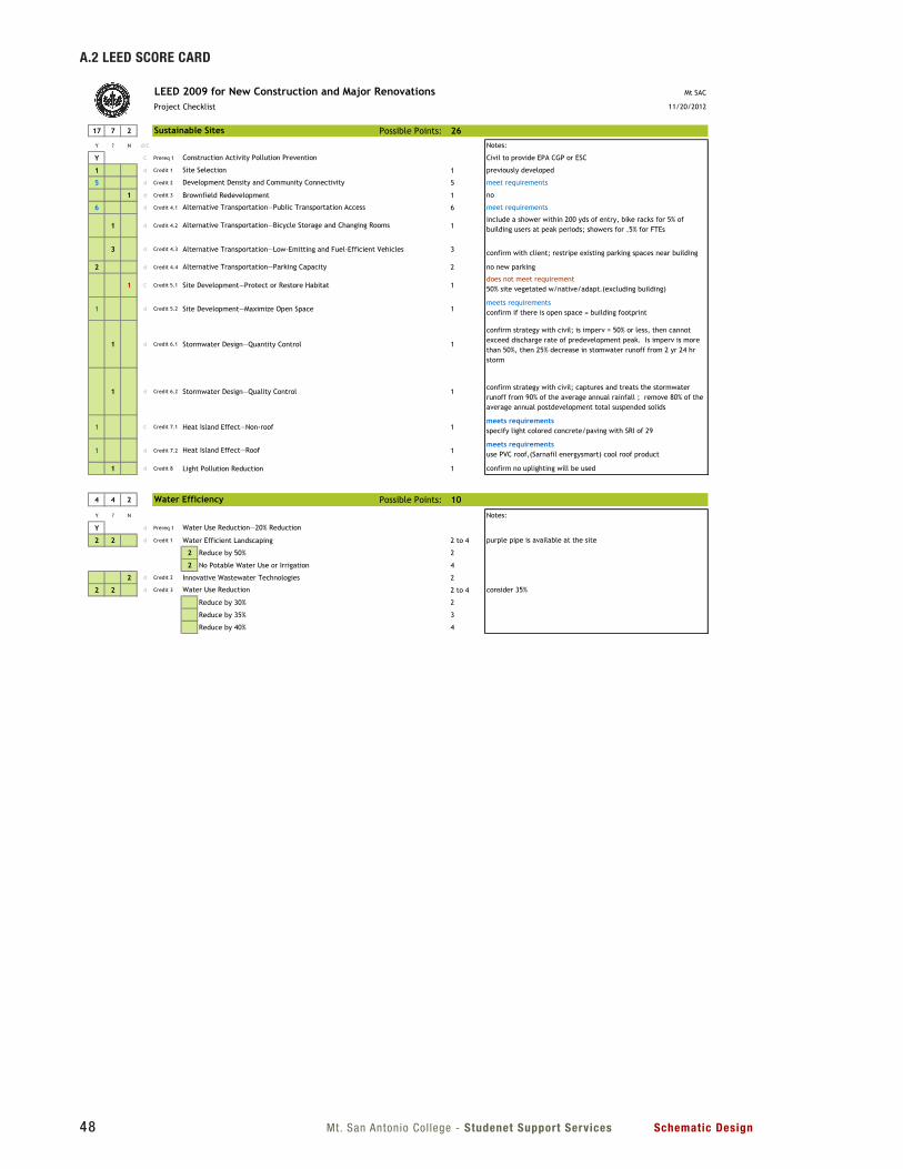
Mt. San Antonio Col lege - Studenet Support Services Schematic Design48
A.2 LEED SCORE CARD
LEED 2009 for New Construction and Major Renovations Mt SAC
Project Checklist 11/20/2012
17 7 2 Possible Points: 26Y ? N d/C Notes:
Y C Prereq 1 Civil to provide EPA CGP or ESC
1 d Credit 1 1 previously developed
5 d Credit 2 5 meet requirements
1 d Credit 3 Brownfield Redevelopment 1 no
6 d Credit 4.1 6 meet requirements
1 d Credit 4.2 1include a shower within 200 yds of entry, bike racks for 5% of building users at peak periods; showers for .5% for FTEs
3 d Credit 4.3 Alternative Transportation—Low-Emitting and Fuel-Efficient Vehicles 3 confirm with client; restripe existing parking spaces near building
2 d Credit 4.4 2 no new parking
1 C Credit 5.1 Site Development—Protect or Restore Habitat 1does not meet requirement50% site vegetated w/native/adapt.(excluding building)
1 d Credit 5.2 Site Development—Maximize Open Space 1meets requirementsconfirm if there is open space = building footprint
1 d Credit 6.1 Stormwater Design—Quantity Control 1
confirm strategy with civil; is imperv = 50% or less, then cannot exceed discharge rate of predevelopment peak. Is imperv is more than 50%, then 25% decrease in stomwater runoff from 2 yr 24 hr storm
1 d Credit 6.2 Stormwater Design—Quality Control 1confirm strategy with civil; captures and treats the stormwater runoff from 90% of the average annual rainfall ; remove 80% of the average annual postdevelopment total suspended solids
1 C Credit 7.1 Heat Island Effect—Non-roof 1meets requirementsspecify light colored concrete/paving with SRI of 29
1 d Credit 7.2 1meets requirementsuse PVC roof,(Sarnafil energysmart) cool roof product
1 d Credit 8 Light Pollution Reduction 1 confirm no uplighting will be used
Construction Activity Pollution Prevention
Site Selection
Development Density and Community Connectivity
Alternative Transportation—Public Transportation Access
Alternative Transportation—Bicycle Storage and Changing Rooms
Sustainable Sites
Alternative Transportation—Parking Capacity
Heat Island Effect—Roof
LEED 2009 for New Construction and Major Renovations Project Checklist 1 of 6
LEED 2009 for New Construction and Major Renovations Mt SAC
Project Checklist 11/20/2012
4 4 2 Possible Points: 10
Y ? N Notes:
Y d Prereq 1
2 2 d Credit 1 Water Efficient Landscaping 2 to 4 purple pipe is available at the site
2 Reduce by 50% 2
2 No Potable Water Use or Irrigation 4
2 d Credit 2 Innovative Wastewater Technologies 2
2 2 d Credit 3 2 to 4 consider 35%
Reduce by 30% 2
Reduce by 35% 3
Reduce by 40% 4
10 17 8 Possible Points: 35
Y ? N Notes:
Y C Prereq 1
Y d Prereq 2
Y d Prereq 3
8 3 8 d Credit 1 1 to 19 20-30% minimum HMC standard; pursue higher %
Improve by 12% for New Buildings or 8% for Existing Building Renovations 1
Improve by 14% for New Buildings or 10% for Existing Building Renovations 2
Improve by 16% for New Buildings or 12% for Existing Building Renovations 3
Improve by 18% for New Buildings or 14% for Existing Building Renovations 4
Improve by 20% for New Buildings or 16% for Existing Building Renovations 5
Improve by 22% for New Buildings or 18% for Existing Building Renovations 6
Improve by 24% for New Buildings or 20% for Existing Building Renovations 7
8 Improve by 26% for New Buildings or 22% for Existing Building Renovations 8
Improve by 28% for New Buildings or 24% for Existing Building Renovations 9
Improve by 30% for New Buildings or 26% for Existing Building Renovations 10
Improve by 32% for New Buildings or 28% for Existing Building Renovations 11
Improve by 34% for New Buildings or 30% for Existing Building Renovations 12
Improve by 36% for New Buildings or 32% for Existing Building Renovations 13
Improve by 38% for New Buildings or 34% for Existing Building Renovations 14
Improve by 40% for New Buildings or 36% for Existing Building Renovations 15
Energy and Atmosphere
Minimum Energy Performance
Optimize Energy Performance
Water Efficiency
Water Use Reduction—20% Reduction
Fundamental Refrigerant Management
Water Use Reduction
Fundamental Commissioning of Building Energy Systems
LEED 2009 for New Construction and Major Renovations Project Checklist 2 of 6
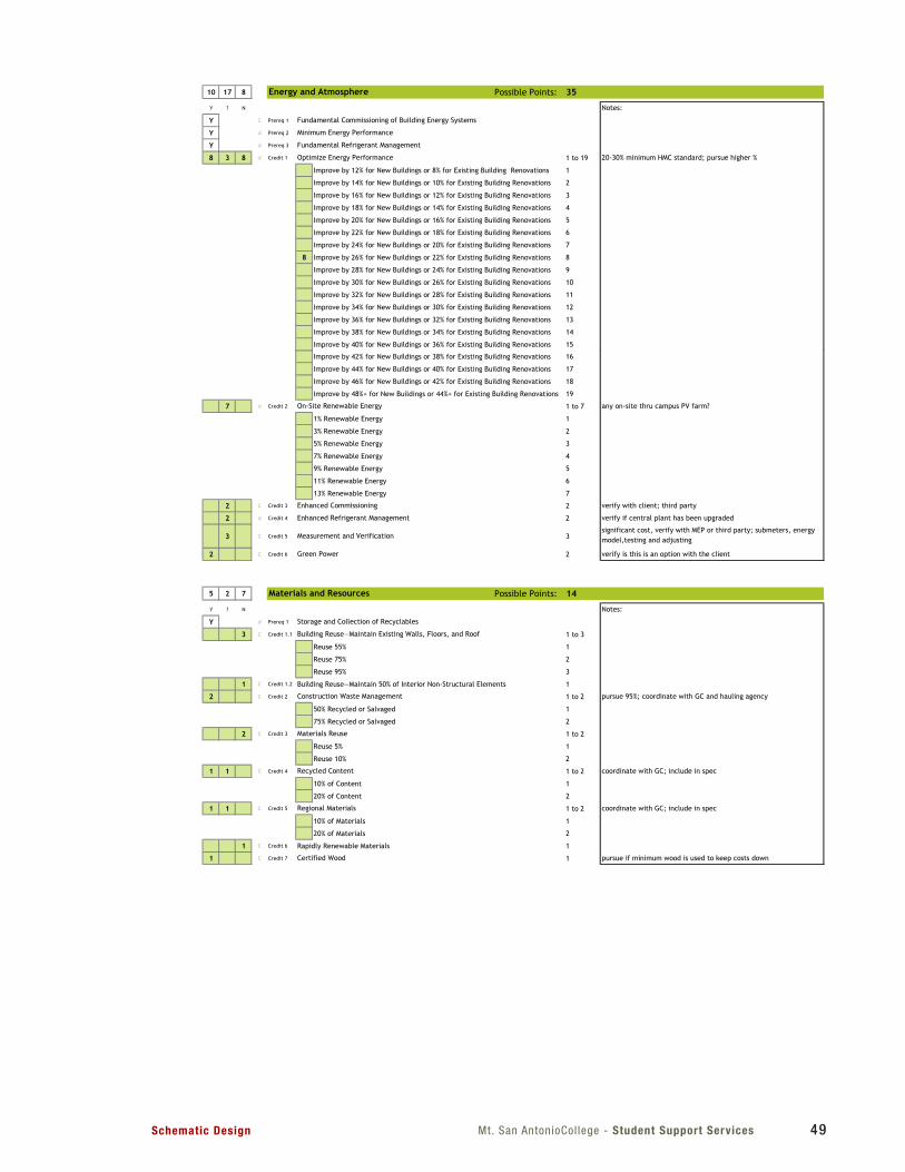
Mt. San AntonioCol lege - Student Support ServicesSchematic Design 49
LEED 2009 for New Construction and Major Renovations Mt SAC
Project Checklist 11/20/2012
Improve by 42% for New Buildings or 38% for Existing Building Renovations 16
Improve by 44% for New Buildings or 40% for Existing Building Renovations 17
Improve by 46% for New Buildings or 42% for Existing Building Renovations 18
Improve by 48%+ for New Buildings or 44%+ for Existing Building Renovations 19
7 d Credit 2 1 to 7 any on-site thru campus PV farm?
1% Renewable Energy 1
3% Renewable Energy 2
5% Renewable Energy 3
7% Renewable Energy 4
9% Renewable Energy 5
11% Renewable Energy 6
13% Renewable Energy 7
2 C Credit 3 2 verify with client; third party
2 d Credit 4 2 verify if central plant has been upgraded
3 C Credit 5 3significant cost, verify with MEP or third party; submeters, energy model,testing and adjusting
2 C Credit 6 2 verify is this is an option with the client
Enhanced Commissioning
Enhanced Refrigerant Management
Measurement and Verification
Green Power
On-Site Renewable Energy
LEED 2009 for New Construction and Major Renovations Project Checklist 3 of 6
LEED 2009 for New Construction and Major Renovations Mt SAC
Project Checklist 11/20/2012
5 2 7 Possible Points: 14
Y ? N Notes:
Y d Prereq 1
3 C Credit 1.1 1 to 3
Reuse 55% 1
Reuse 75% 2
Reuse 95% 3
1 C Credit 1.2 Building Reuse—Maintain 50% of Interior Non-Structural Elements 1
2 C Credit 2 1 to 2 pursue 95%; coordinate with GC and hauling agency
50% Recycled or Salvaged 1
75% Recycled or Salvaged 2
2 C Credit 3 1 to 2
Reuse 5% 1
Reuse 10% 2
1 1 C Credit 4 1 to 2 coordinate with GC; include in spec
10% of Content 1
20% of Content 2
1 1 C Credit 5 1 to 2 coordinate with GC; include in spec
10% of Materials 1
20% of Materials 2
1 C Credit 6 Rapidly Renewable Materials 1
1 C Credit 7 1 pursue if minimum wood is used to keep costs down
Regional Materials
Certified Wood
Storage and Collection of Recyclables
Building Reuse—Maintain Existing Walls, Floors, and Roof
Construction Waste Management
Materials Reuse
Recycled Content
Materials and Resources
LEED 2009 for New Construction and Major Renovations Project Checklist 4 of 6
LEED 2009 for New Construction and Major Renovations Mt SAC
Project Checklist 11/20/2012
4 4 2 Possible Points: 10
Y ? N Notes:
Y d Prereq 1
2 2 d Credit 1 Water Efficient Landscaping 2 to 4 purple pipe is available at the site
2 Reduce by 50% 2
2 No Potable Water Use or Irrigation 4
2 d Credit 2 Innovative Wastewater Technologies 2
2 2 d Credit 3 2 to 4 consider 35%
Reduce by 30% 2
Reduce by 35% 3
Reduce by 40% 4
10 17 8 Possible Points: 35
Y ? N Notes:
Y C Prereq 1
Y d Prereq 2
Y d Prereq 3
8 3 8 d Credit 1 1 to 19 20-30% minimum HMC standard; pursue higher %
Improve by 12% for New Buildings or 8% for Existing Building Renovations 1
Improve by 14% for New Buildings or 10% for Existing Building Renovations 2
Improve by 16% for New Buildings or 12% for Existing Building Renovations 3
Improve by 18% for New Buildings or 14% for Existing Building Renovations 4
Improve by 20% for New Buildings or 16% for Existing Building Renovations 5
Improve by 22% for New Buildings or 18% for Existing Building Renovations 6
Improve by 24% for New Buildings or 20% for Existing Building Renovations 7
8 Improve by 26% for New Buildings or 22% for Existing Building Renovations 8
Improve by 28% for New Buildings or 24% for Existing Building Renovations 9
Improve by 30% for New Buildings or 26% for Existing Building Renovations 10
Improve by 32% for New Buildings or 28% for Existing Building Renovations 11
Improve by 34% for New Buildings or 30% for Existing Building Renovations 12
Improve by 36% for New Buildings or 32% for Existing Building Renovations 13
Improve by 38% for New Buildings or 34% for Existing Building Renovations 14
Improve by 40% for New Buildings or 36% for Existing Building Renovations 15
Energy and Atmosphere
Minimum Energy Performance
Optimize Energy Performance
Water Efficiency
Water Use Reduction—20% Reduction
Fundamental Refrigerant Management
Water Use Reduction
Fundamental Commissioning of Building Energy Systems
LEED 2009 for New Construction and Major Renovations Project Checklist 2 of 6
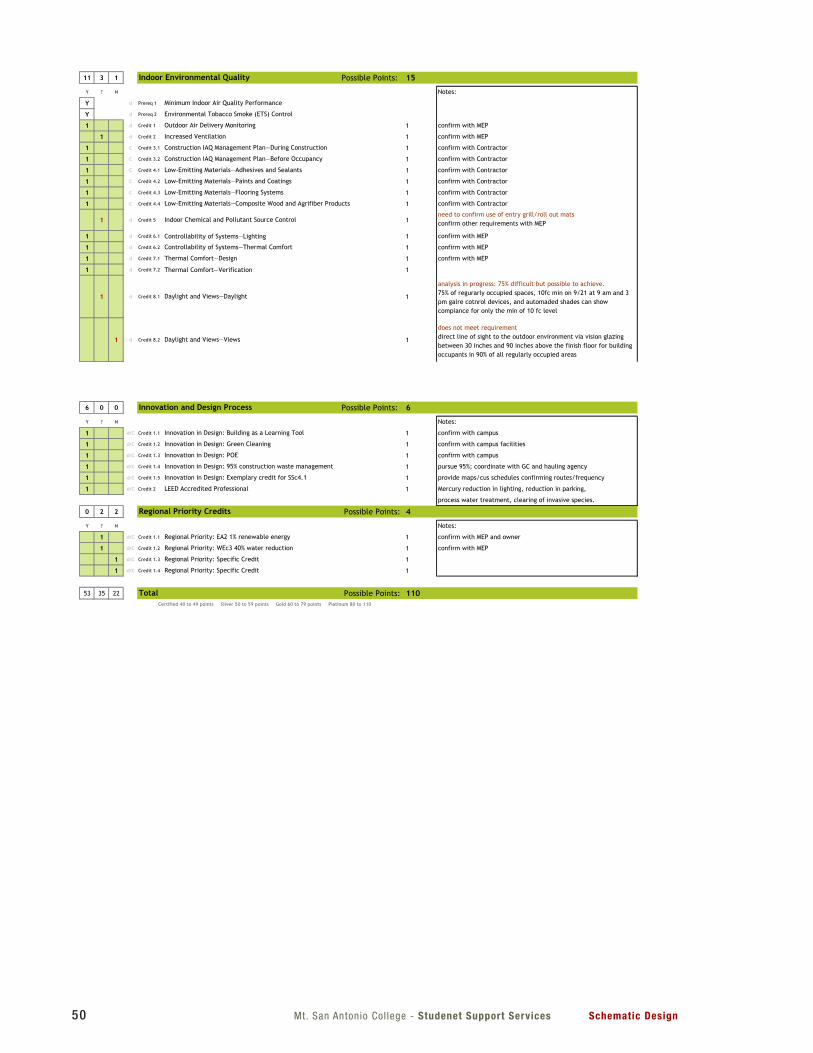
Mt. San Antonio Col lege - Studenet Support Services Schematic Design50
LEED 2009 for New Construction and Major Renovations Mt SAC
Project Checklist 11/20/2012
6 0 0 Possible Points: 6
Y ? N Notes:
1 d/C Credit 1.1 1 confirm with campus
1 d/C Credit 1.2 1 confirm with campus facilities
1 d/C Credit 1.3 1 confirm with campus
1 d/C Credit 1.4 1 pursue 95%; coordinate with GC and hauling agency
1 d/C Credit 1.5 1 provide maps/cus schedules confirming routes/frequency
1 d/C Credit 2 1 Mercury reduction in lighting, reduction in parking,
process water treatment, clearing of invasive species.
0 2 2 Possible Points: 4
Y ? N Notes:
1 d/C Credit 1.1 1 confirm with MEP and owner
1 d/C Credit 1.2 1 confirm with MEP
1 d/C Credit 1.3 1
1 d/C Credit 1.4 1
53 35 22 Possible Points: 110Certified 40 to 49 points Silver 50 to 59 points Gold 60 to 79 points Platinum 80 to 110
Innovation and Design Process
Total
Regional Priority Credits
Innovation in Design: Building as a Learning Tool
Innovation in Design: Green Cleaning
LEED Accredited Professional
Regional Priority: EA2 1% renewable energy
Regional Priority: WEc3 40% water reduction
Regional Priority: Specific Credit
Regional Priority: Specific Credit
Innovation in Design: POE
Innovation in Design: 95% construction waste management
Innovation in Design: Exemplary credit for SSc4.1
LEED 2009 for New Construction and Major Renovations Project Checklist 6 of 6
LEED 2009 for New Construction and Major Renovations Mt SAC
Project Checklist 11/20/2012
11 3 1 Possible Points: 15
Y ? N Notes:
Y d Prereq 1
Y d Prereq 2
1 d Credit 1 1 confirm with MEP
1 d Credit 2 1 confirm with MEP
1 C Credit 3.1 1 confirm with Contractor
1 C Credit 3.2 1 confirm with Contractor
1 C Credit 4.1 1 confirm with Contractor
1 C Credit 4.2 1 confirm with Contractor
1 C Credit 4.3 1 confirm with Contractor
1 C Credit 4.4 1 confirm with Contractor
1 d Credit 5 1need to confirm use of entry grill/roll out matsconfirm other requirements with MEP
1 d Credit 6.1 Controllability of Systems—Lighting 1 confirm with MEP
1 d Credit 6.2 1 confirm with MEP
1 d Credit 7.1 1 confirm with MEP
1 d Credit 7.2 Thermal Comfort—Verification 1
1 d Credit 8.1 1
analysis in progress: 75% difficult but possible to achieve.75% of regurarly occupied spaces, 10fc min on 9/21 at 9 am and 3 pm galre cotnrol devices, and automaded shades can show compiance for only the min of 10 fc level
1 d Credit 8.2 1
does not meet requirementdirect line of sight to the outdoor environment via vision glazing between 30 inches and 90 inches above the finish floor for building occupants in 90% of all regularly occupied areas
Indoor Chemical and Pollutant Source Control
Controllability of Systems—Thermal Comfort
Thermal Comfort—Design
Daylight and Views—Daylight
Daylight and Views—Views
Construction IAQ Management Plan—During Construction
Construction IAQ Management Plan—Before Occupancy
Low-Emitting Materials—Adhesives and Sealants
Low-Emitting Materials—Paints and Coatings
Low-Emitting Materials—Flooring Systems
Low-Emitting Materials—Composite Wood and Agrifiber Products
Minimum Indoor Air Quality Performance
Environmental Tobacco Smoke (ETS) Control
Outdoor Air Delivery Monitoring
Increased Ventilation
Indoor Environmental Quality
LEED 2009 for New Construction and Major Renovations Project Checklist 5 of 6
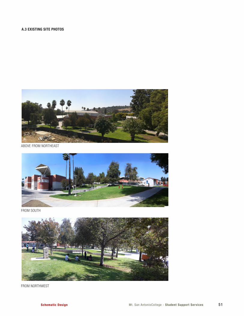
Mt. San AntonioCol lege - Student Support ServicesSchematic Design 51
A.3 EXISTING SITE PHOTOS
ABOVE FROM NORTHEAST
FROM SOUTH
FROM NORTHWEST
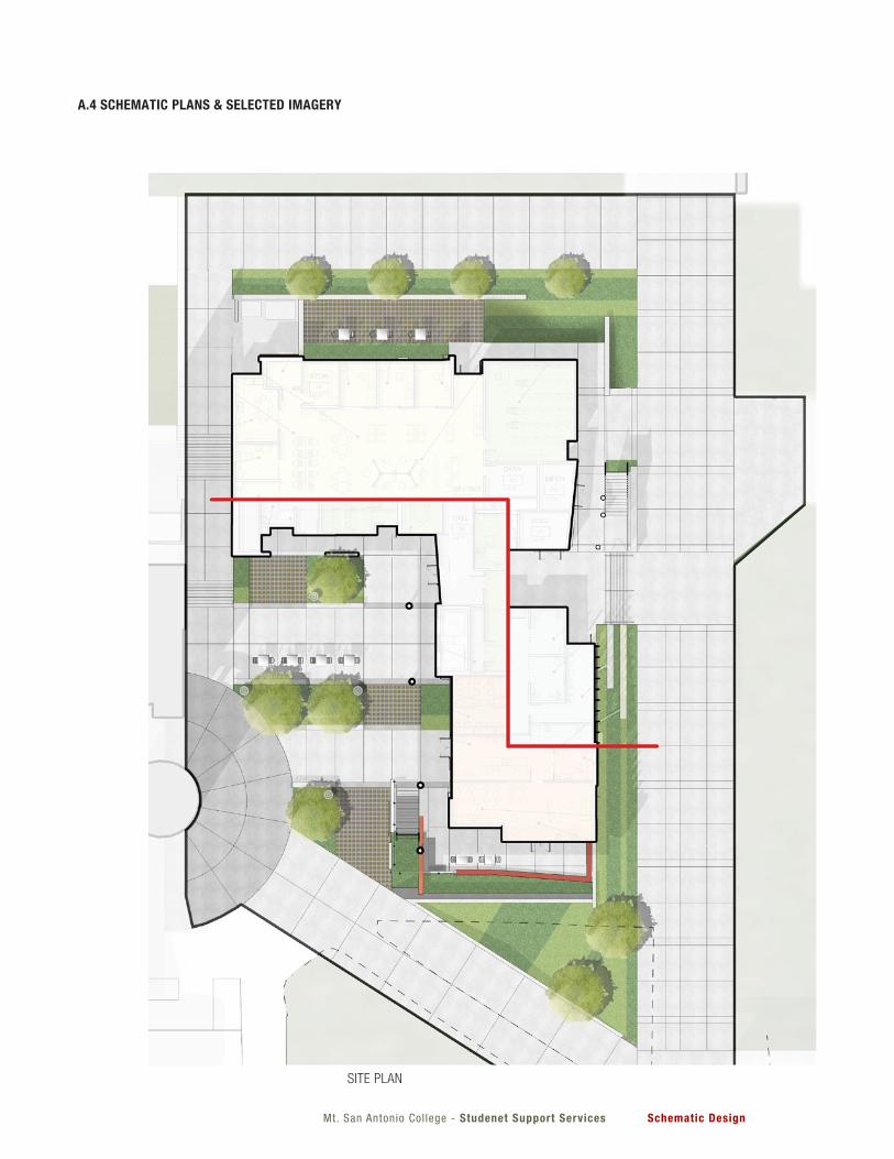
Mt. San Antonio Col lege - Studenet Support Services Schematic Design
SITE PLAN
A.4 SCHEMATIC PLANS & SELECTED IMAGERY
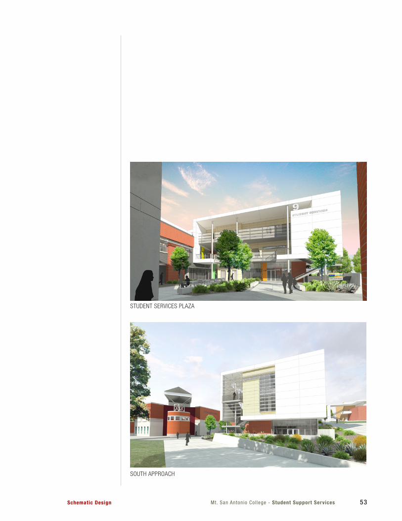
Mt. San Antonio Col lege - Student Support ServicesSchematic Design 53
STUDENT SERVICES PLAZA
SOUTH APPROACH
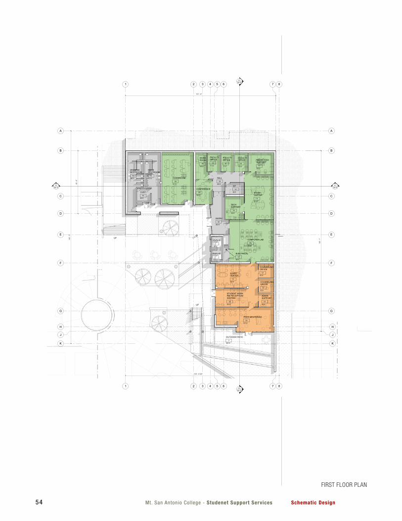
Mt. San Antonio Col lege - Studenet Support Services Schematic Design54
1
1
H1A6.10
H1A6.10
A1A6.10
A1A6.10
DD
HH
5
5
7
7
4
4
GG
FF
EE
6
6
3
3
CC
AA
BB
8
8
JJ
2
2
KK
721 SF
CLASSROOM104
613 SF
STUDYCENTER
115
111 SF
FACULTYOFFICE
107
113 SF
FACULTYOFFICE
105111 SF
FACULTYOFFICE
106
186 SF
CONFERENCE110
192 SF
TECHSUPPORT
114
239 SF
MEDIA TECHSUPPORT
111143 SF
WORKROOM
108
365 SF
STUDENT WORKRM/ RECEPTION/WAITING
120
467 SF
STUDYCENTER
119
577 SF
PEER MENTORING124
96 SF
ADMINSUPPORT
123
95 SF
COUNSELINGOFFICE
122
95 SF
COUNSELINGOFFICE
121
340 SF
WOMENSRESTROOM
101
80 SF
CUST.103
312 SF
MENSRESTROOM
102
282 SF
ENTRY109
137 SF
ELEV 01-
98 SF
IDF112
Redundant Room
ELEV 02-
38 SF
ELECTRICAL117
535 SF
OUTDOOR PATIO0
103' - 9 3/4"
143'
- 7"
206 SF
HALL235
42' -
6"
101' - 6"
122'
- 1"
UP
UP
851 SF
COMPUTER LAB116
FIRST FLOOR PLAN
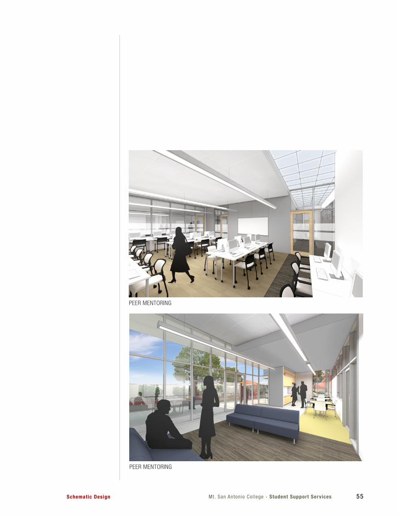
Mt. San Antonio Col lege - Student Support ServicesSchematic Design 55
PEER MENTORING
PEER MENTORING
FIRST FLOOR PLAN
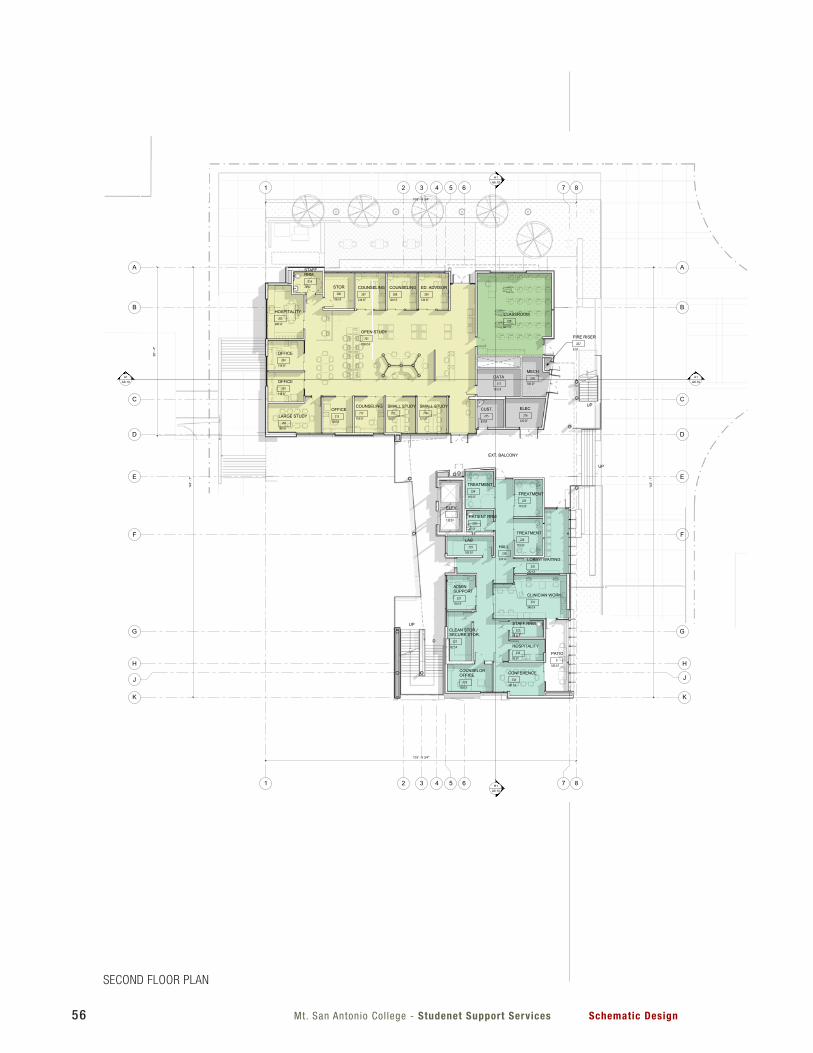
Mt. San Antonio Col lege - Studenet Support Services Schematic Design56
1
1 H1A6.10
H1A6.10
A1A6.10
A1A6.10
DD
HH
5
5
7
7
4
4
GG
FF
EE
6
6
3
3
CC
AA
BB
8
8
JJ
2
2
KK
120 SF
ED. ADVISOR209
200 SF
HOSPITALITY205
120 SF
COUNSELING208
118 SF
OFFICE204
118 SF
OFFICE203
185 SF
LARGE STUDY202
121 SF
SMALL STUDY210
120 SF
SMALL STUDY211
83 SF
CUST.215
120 SF
COUNSELING207
118 SF
COUNSELING212
667 SF
CLASSROOM220
105 SF
MECH218
125 SF
ELEC216
133 SF
DATA217
181 SF
CONFERENCE234
138 SF
COUNSELOROFFICE
223
110 SF
ADMINSUPPORT
221
82 SF
HOSPITALITY233
242 SF
LOBBY/ WAITING232
524 SF
HALL228
340 SF
CLINICIAN WORK231
67 SF
PATIENT RRM230
103 SF
LAB229
132 SF
CLEAN STOR./SECURE STOR.
227
119 SF
TREATMENT226
119 SF
TREATMENT225
119 SF
TREATMENT224
1834 SF
OPEN STUDY201
66 SF
STAFF RRM.222
133 SF
ELEV.-
183 SF
PATIO0
118 SF
STOR206
118 SF
OFFICE213
70 SF
STAFFRRM.
214
103' - 9 3/4"
103' - 9 3/4"
143'
- 7"
143'
- 7"
8 SF
FIRE RISER237
56' -
4"
D
UP
UP
UP
EXT. BALCONY
SECOND FLOOR PLAN
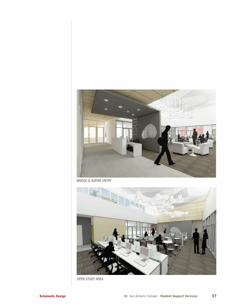
Mt. San Antonio Col lege - Student Support ServicesSchematic Design 57
BRIDGE & ASPIRE ENTRY
OPEN STUDY AREA
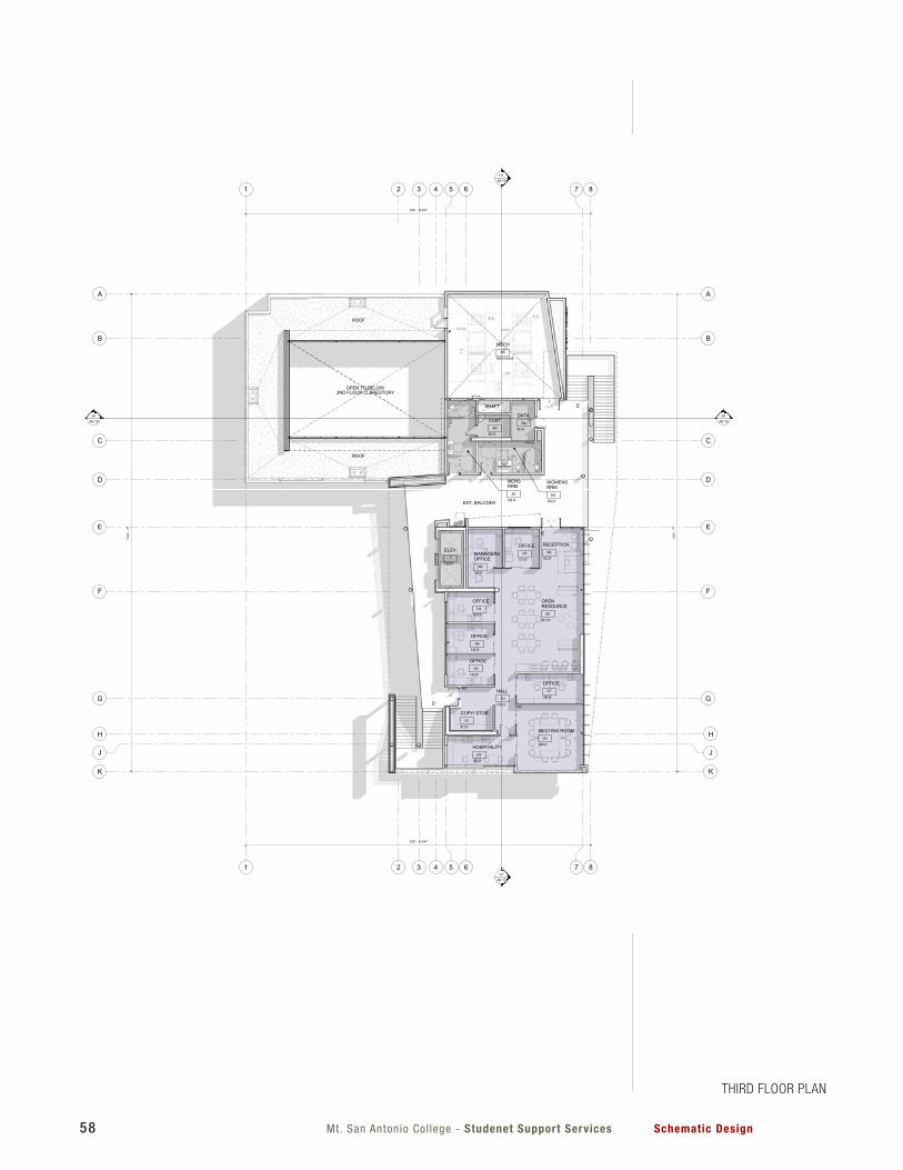
Mt. San Antonio Col lege - Studenet Support Services Schematic Design58
1
1H1
A6.10
H1A6.10
A1A6.10
A1A6.10
DD
HH
5
5
7
7
4
4
GG
FF
EE
6
6
3
3
CC
AA
BB
8
8
JJ
2
2
KK
156 SF
RECEPTION306
817 SF
OPENRESOURCE
307124 SF
OFFICE316
121 SF
OFFICE315
168 SF
MANAGERSOFFICE
308
124 SF
OFFICE309
124 SF
OFFICE310
388 SF
MEETING ROOM314
183 SF
HOSPITALITY313
170 SF
HALL312
183 SF
MENSRRM
301
164 SF
WOMENSRRM
302
69 SF
CUST303 85 SF
DATA304
Not Enclosed
MECH305
97 SF
COPY/ STOR.311
138 SF
ELEV.-
SHAFT
103' - 9 3/4"
OPEN TO BELOW
ROOF
ROOF
2ND FLOOR CLERESTORY
103' - 9 3/4"
143'
- 7"
143'
- 7"
180 SF
OFFICE317
D
D
EXT. BALCONY
THIRD FLOOR PLAN
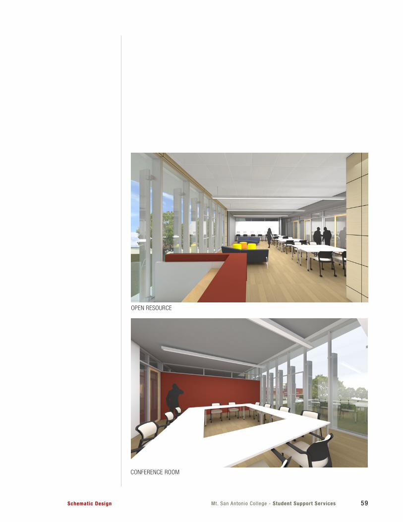
Mt. San Antonio Col lege - Student Support ServicesSchematic Design 59
OPEN RESOURCE
CONFERENCE ROOM
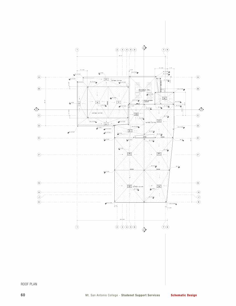
Mt. San Antonio Col lege - Studenet Support Services Schematic Design60
1
1H1
A6.10
H1A6.10
A1A6.10
A1A6.10
DD
HH
5
5
7
7
4
4
GG
FF
EE
6
6
3
3
CC
AA
BB
8
8
JJ
2
2
KK
101' - 6"
RIDGERIDGE
RIDGE
RID
GE
MECHANICAL WELL+ 31'-0" F.F.
3' - 0"
7' - 9"
26' -
9"
11 3
/4"
2' -
6 3/
4"2'
- 10
1/2
"11' - 7 1/4" 4 1/2"
14' - 3 3/4"
12' -
11"
1' - 2 1/4"
1' - 4 1/2"
55' -
10"
103' - 9 3/4"
OPEN
1/4" PER 1'-0" TYP.
1/4" PER 1'-0" TYP.
1/4" PER 1'-0" TYP.
1/4" PER 1'-0" TYP.
46' - 6" T.O.R.46' - 6" T.O.R.
46' - 6" T.O.R.
46' - 6" T.O.R.
46' - 6" T.O.R.
46' - 6" T.O.R.
46' - 6" T.O.R.
46' - 6" T.O.R.
40' - 6" T.O.R. 40' - 6" T.O.R.
40' - 6" T.O.R. 40' - 6" T.O.R.
33' - 0" T.O.P.
33' - 0" T.O.P.
33' - 0" T.O.P.
44' - 0" T.O.P.
44' - 0" T.O.P.
44' - 0" T.O.P.
37' - 0" T.O.P.
33' - 0" T.O.P.
143'
- 7"
46' - 0" R.D.
46' - 0" R.D.
46' - 0" R.D.46' - 0" R.D.
46' - 0" R.D.46' - 0" R.D.
40' - 0" R.D.
40' - 0" R.D.
31' - 0" R.D.
31' - 0" R.D.
31' - 0" R.D.
46' - 0" R.D.
37' - 0" T.O.P.
46' - 0" R.D.
46' - 6" T.O.R.
46' - 6" T.O.R.
46' - 6"
46' - 6"
46' - 6" T.O.R.
37' - 0" T.O.P.
46' - 6" T.O.R.
46' - 6" T.O.R.
46' - 6" T.O.R.
46' - 6" T.O.R.
46' - 6" T.O.R.
46' - 6"
46' - 6" T.O.R.
46' - 6" T.O.R.
ROOF ACCESSLADDER
ROOF PLAN
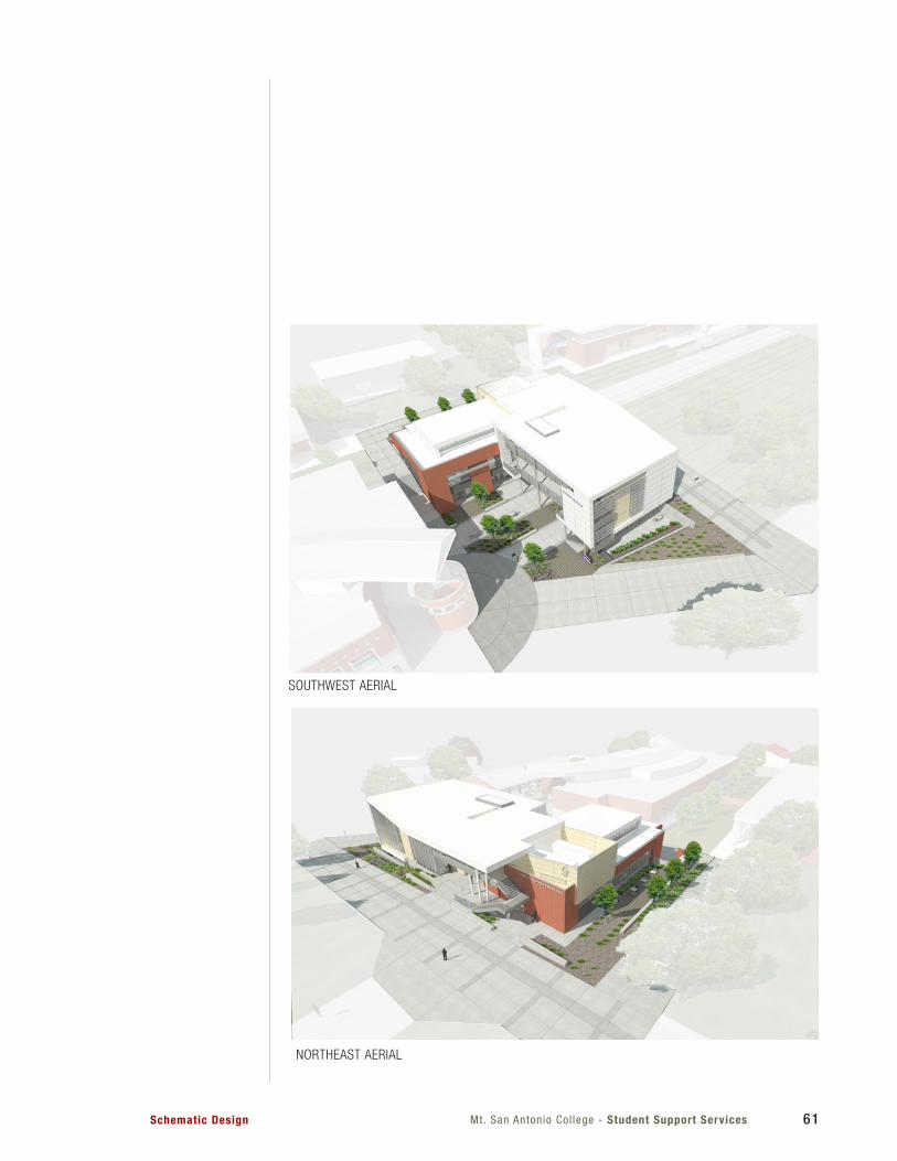
Mt. San Antonio Col lege - Student Support ServicesSchematic Design 61
SOUTHWEST AERIAL
NORTHEAST AERIAL
Mt. San Antonio Col lege - Studenet Support Services Schematic Design