Embed Size (px)
Citation preview
research papers
Acta Cryst. (2012). B68, 559–570 doi:10.1107/S0108768112039961 559
Acta Crystallographica Section B
StructuralScience
ISSN 0108-7681
Structural transformation of Sb-based high-speedphase-change material
Toshiyuki Matsunaga,a* Rie
Kojima,b Noboru Yamada,c
Yoshiki Kubotad and Kouichi
Kifunee
aDevice Solutions Center, R&D Division, Pana-
sonic Corporation, 3-1-1 Yagumo-Nakamachi,
Moriguchi, Osaka 570-8501, Japan, bAVC
Networks Company, Panasonic Corporation, 1-
15 Matsuo-cho, Kadoma, Osaka 571-8504,
Japan, cDepartment of Materials Science &
Engineering, Kyoto University, Yoshida-
honmachi, Sakyo-ku, Kyoto 606-8501, Japan,dGraduate School of Science, Osaka Prefecture
University, 1-1 Gakuen-cho, Sakai, Osaka 599-
8531, Japan, and eFaculty of Liberal Arts and
Sciences, Osaka Prefecture University, 1-1
Gakuen-cho, Sakai, Osaka 599-8531, Japan
Correspondence e-mail:
# 2012 International Union of Crystallography
Printed in Singapore – all rights reserved
The crystal structure of a phase-change recording material
(the compound Ag3.4In3.7Sb76.4Te16.5) enclosed in a vacuum
capillary tube was investigated at various temperatures in a
heating process using a large Debye–Scherrer camera installed
in BL02B2 at SPring-8. The amorphous phase of this material
turns into a crystalline phase at around 416 K; this crystalline
phase has an A7-type structure with atoms of Ag, In, Sb or Te
randomly occupying the 6c site in the space group. This
structure was maintained up to around 545 K as a single phase,
although thermal expansion of the crystal lattice was
observed. However, above this temperature, phase separation
into AgInTe2 and Sb–Te transpired. The first fragment,
AgInTe2, reliably maintained its crystal structure up to the
melting temperature. On the other hand, the atomic config-
uration of the Sb–Te gradually varied with increasing
temperature. This gradual structural transformation can be
described as a continuous growth of the modulation period �.
Received 28 March 2012
Accepted 20 September 2012
B-IncStrDB Reference:
6732EXfQbW
1. Introduction
Phase change recording is now extensively used for high-
density non-volatile memories (Wuttig & Yamada, 2007).
Since the 1970s, various materials have been proposed for this
purpose, and today we have obtained two superior materials:
GeTe–Sb2Te3 (GST) (Yamada et al., 1991) and Sb–Te-based
alloys such as Ag3.4In3.7Sb76.4Te16.5 (AIST or silver indium
antimony tellurium; Iwasaki et al., 1992); these materials are
now practically used as the memory layers in phase-change
optical disk media, as well as in the memory cells of solid-state
electrical memories. Recording can be achieved using laser
irradiation or ohmic heating to cause reversible phase changes
between the amorphous and crystalline phases. We analyzed
the crystal structure of AIST about 10 years ago (Matsunaga et
al., 2001), revealing that AIST has an A7-type structure, the
same as that of pure Sb, in which four elements randomly
occupy the 6c site in the space group. It has been presumed
that this simple and spatially isotropic p–p connected six-
coordination structure enables instantaneous transformation
from the amorphous phase to the crystalline phase by minimal
atomic rearrangement (Matsunaga et al., 2006; Matsunaga,
Yamada et al., 2011). Our analysis also revealed that this A7-
type quaternary crystal held its rhombohedral structure,
showing a continuous atomic shift along the axis from z =
0.233 to 1/4, when the temperature was raised close to the
melting point. We examined the crystal structures of Sb–Te
binary compounds, which are the mother alloys of the AIST
materials, as well as those of Bi–Te compounds. These
compounds are known, in thermal equilibrium, to have a
series of commensurately or incommensurately modulated
long-period layer structures, depending on their binary
compositions, between Sb and Sb2Te3 or between Bi and
Bi2Te3. Our present investigation of an as-deposited
Ag3.4In3.7Sb76.4Te16.5 amorphous film in a sealed quartz tube
revealed that when the temperature was raised, this
quaternary alloy maintained an A7-type structure, hardly
showing any atomic shift. However, decomposition into two
phases, AgInTe2 and Sb–Te, occurred at around 545 K. After
this decomposition, the atomic configuration of the Sb–Te
fragment with the A7-type disordered structure gradually
moved into an ordered arrangement to finally obtain a stable
homologous structure ruled by its composition. This can be
considered as follows: the dopants, Ag and In, played roles in
simplifying the structure of the quaternary alloy. However,
once these dopants were lost, the structural feature of the Sb–
Te binary compound revealed itself.
2. Experimental
A thin film of Ag3.4In3.7Sb76.4Te16.5 with a thickness of
approximately 300 nm was formed by sputtering on a glass
disk 120 mm in diameter. The film was scraped off with a
spatula to create a powder, which was then packed into a
quartz capillary tube with an internal diameter of 0.3 mm. To
prevent it from reacting with components of air, we sealed the
opening of the capillary tube using an oxyacetylene flame. The
diffraction experiments were carried out using the large-
diameter Debye–Scherrer camera with an imaging plate on
the BL02B2 beamline at the Japan Synchrotron Radiation
Research Institute (Nishibori et al., 2001). The energy of the
incident beam was approximately 29.4 keV. An imaging plate
with a pixel area of 100 mm2 was used as the detector; this pixel
area corresponded to an angular resolution of 0.02� (287 mm
camera diameter). However, for more precise structure
analyses, intensity data in increments of 0.01� were obtained
by reading the imaging plate for a pixel area of 50 mm2.
Experiments at low and high temperatures were carried out
while blowing nitrogen gas onto the capillary tube at the
specified temperatures. The crystal structures were examined
and refined using the Rietveld method (Rietveld, 1969); the
programs JANA2000 (Petrıcek & Dusek, 2000) and
JANA2006 (Petrıcek et al., 2006) were used for this purpose.
The energy of the synchrotron radiation was confirmed by
recording the diffraction intensity of CeO2 (a = 5.4111 A)
powder as a reference specimen at room temperature under
research papers
560 Toshiyuki Matsunaga et al. � Sb-based high-speed phase-change material Acta Cryst. (2012). B68, 559–570
Table 1Final structural parameters for Ag3.4In3.7Sb76.4Te16.5 at 545 K refined byRietveld analysis.
The standard deviations are shown in parentheses. The diffraction data usedfor the analysis: 5.50 � 2� � 31.50�. (a) Conventional three-dimensionalRietveld analysis results. The space group R�33m was applied. (b) Results of afour-dimensional superspace analysis refined as a commensurately modulatedstructure, using the ‘commensurate case’ in the refinement program JANA;the modulation period � was maintained at 3/2 during the refinements (theanalysis assuming an incommensurate case also concluded that this crystal hasa commensurate structure with � = 3/2). The superspace group was assumed tobe R3m 00�ð Þ00 (de Wolff, 1974; de Wolff et al., 1981). Bs
1 represents thepositional modulation amplitude. The determined z-slope (the form factor ofthe sawtooth function) value corresponds to z = 0.2359 in the three-dimensional description; this z value shows good agreement with z = 0.2365,which was derived from the three-dimensional analysis. Uij represent theatomic displacement parameters. It was assumed that the four atoms randomlyoccupy the atomic sites in both analyses.
(a) Rp = 0.0215, Rwp = 0.0313, RFobs = 0.0157, RFwobs = 0.0238, a = 4.3037 (5)and c = 11.290 (1) A. M: Ag0.034In0.037Sb0.764Te0.165.
Atom Site g x y z U11 (A2) U33 (A2)
M 6c 1.0 0 0 0.2365 (1) 0.0235 (5) 0.042 (2)
(b) Commensurate case (t0 ¼14 ;
34).
R factors of profile and all reflectionsRp 0.0202Rwp 0.0292RFobs 0.0133RFwobs 0.0198
R factors of main and satellite reflectionsMain RFobs 0.0111
RFwobs 0.0141
R factors of satellitesFirst-order RFobs 0.0184
RFwobs 0.0273
� = 3/2; a = 4.3037 (5), c = 5.6452 (6) A
Atom g x y z z-slope U11 (A2) U33 (A2)
M 1.0 0 0 0 �0.0563 (8) 0.0229 (5) 0.043 (1)
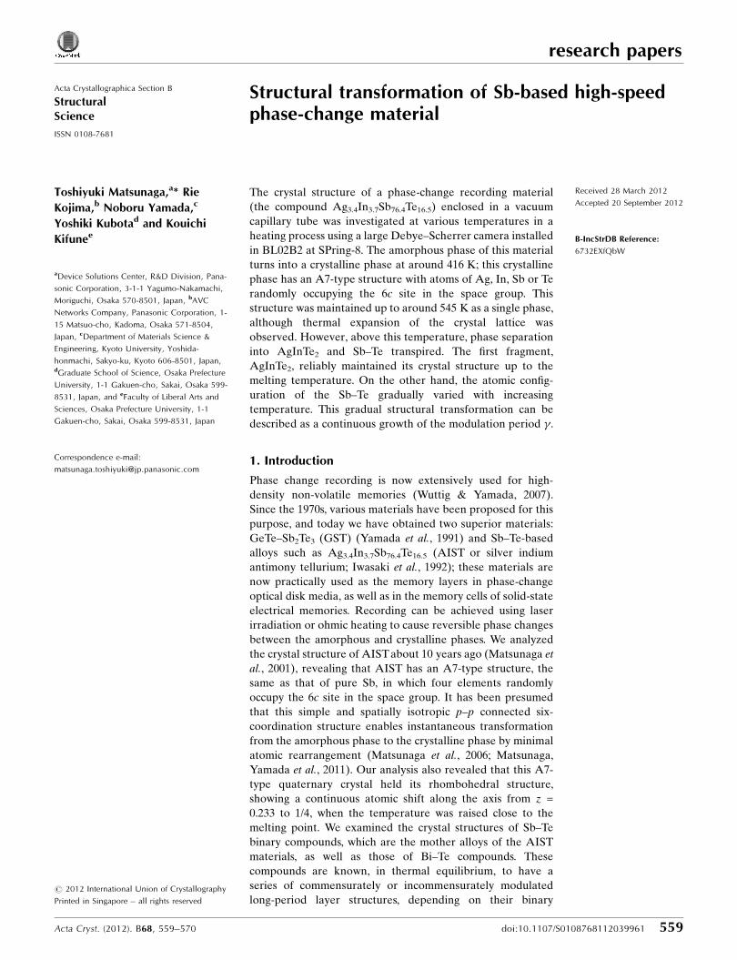
Figure 1Temperature dependence of X-ray powder diffraction profiles forsputtered Ag3.4In3.7Sb76.4Te16.5 amorphous film in the heating process.The amorphous halo patterns are observed at low temperatures from 295to 416 K. However, at around 416 K the Bragg peaks of the A7-typestructure appear in the halo pattern. As the temperature is raised further,the A7-type single phase separates into two phases, AgInTe2 and an Sb–Te binary compound, at around 545 K. At 2� angles lower than 5�, Braggpeaks were hardly observed at any measurement temperatures.
the same conditions, which
showed that the wavelength used
for the structural analyses was
0.4187 (3) A. Neutral atomic
scattering factors were employed
for them.
3. Results and discussion
3.1. Crystals observed in thisexperiment
The diffraction patterns
obtained for the sputtered
Ag3.4In3.7Sb76.4Te16.5 amorphous
film are shown in Fig. 1. The
amorphous phase transformed
into an A7-type crystalline single
phase, as seen in this graph, at
around 416 K. The results of a
search match and Rietveld
analyses revealed the diffraction
patterns taken from 435 to 545 K
to be almost identical to that of
an As, Sb or Bi crystal with an
A7-type structure (Clark, 1955),
as has been previously elucidated
(Matsunaga et al., 2001). The
(conventional three-dimensional)
Rietveld analysis results at 545 K are shown in Table 1(a). This
crystal belongs to the space group R�33m; the four constituent
elements, Ag, In, Sb and Te, randomly occupy the 6c site
(Matsunaga, Akola et al., 2011). The changes in the diffraction
lines with increasing temperature show that the single-phase
A7-type structure is maintained up to around 545 K. However,
the peaks for CuFeS2-type AgInTe2 (Wyckoff, 1986) appear at
around 590 K, along with those of the A7-type structure. This
decomposition can be written as
Ag3:4In3:7Sb76:4Te16:5 ! Ag3:4In3:4Te6:8 þ In0:3Sb76:4Te9:7:
ð1Þ
These two phases formed by heating coexisted up to the high
temperatures at which their Bragg peaks almost disappeared
as a result of dissolving. As seen in this equation, the second
decomposition product can virtually be regarded as an Sb–Te
binary compound. Even at high temperatures close to the
melting temperature, AgInTe2 tightly held the CuFeS2-type
structure irrespective of temperature. However, our present
analysis revealed that the structure of the second fragment,
the Sb–Te compound, gradually changed with increasing
temperature until obtaining its final stable atomic configura-
tion. These structures can be closely approximated by the A7-
type structure but are not real A7-type ones.
3.2. Homologous structures
We examined many types of chalcogenide materials to
clarify the high-speed phase-change mechanism and develop
research papers
Acta Cryst. (2012). B68, 559–570 Toshiyuki Matsunaga et al. � Sb-based high-speed phase-change material 561
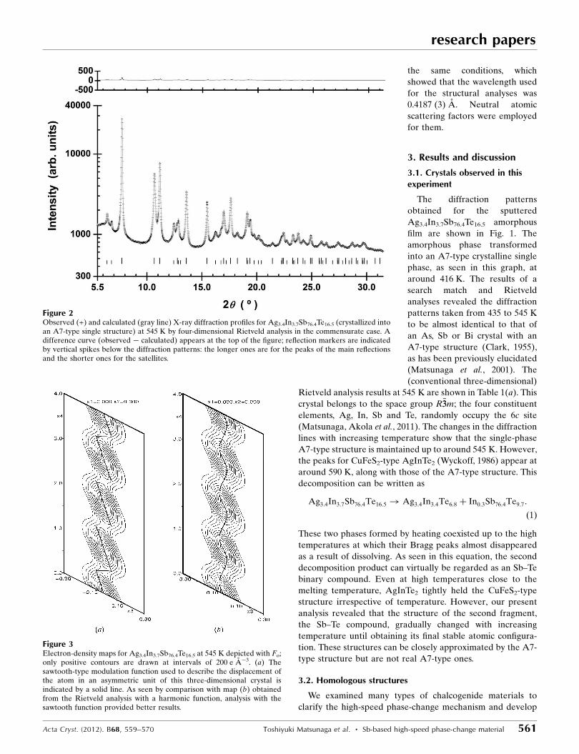
Figure 2Observed (+) and calculated (gray line) X-ray diffraction profiles for Ag3.4In3.7Sb76.4Te16.5 (crystallized intoan A7-type single structure) at 545 K by four-dimensional Rietveld analysis in the commensurate case. Adifference curve (observed � calculated) appears at the top of the figure; reflection markers are indicatedby vertical spikes below the diffraction patterns: the longer ones are for the peaks of the main reflectionsand the shorter ones for the satellites.
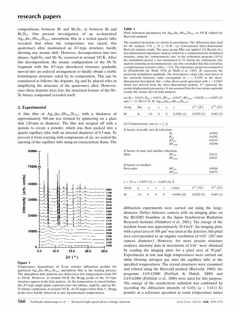
Figure 3Electron-density maps for Ag3.4In3.7Sb76.4Te16.5 at 545 K depicted with Fo;only positive contours are drawn at intervals of 200 e A�3. (a) Thesawtooth-type modulation function used to describe the displacement ofthe atom in an asymmetric unit of this three-dimensional crystal isindicated by a solid line. As seen by comparison with map (b) obtainedfrom the Rietveld analysis with a harmonic function, analysis with thesawtooth function provided better results.
new materials for future ultra-high-density phase-change
recording devices. This revealed that, after sufficient heat
treatments, almost all these materials finally fell into their
stable crystals with so-called homologous structures. It has
been found that in thermal equilibrium, the typical phase-
change materials, the GeTe–Sb2Te3 pseudobinary system, the
Sb–Te or Bi–Te binary system, form various intermetallic
compounds represented by the chemical formulae
(GeTe)n(Sb2Te3)m, (Sb2)n(Sb2Te3)m or (Bi2)n(Bi2Te3)m (n, m:
integer). All these compounds have trigonal structures with 2n
+ 5m cubic close-packed periodicity (almost) without excep-
tion. [More specifically, the residual of (2n + 5m)/3 = 0 and 6¼ 0
leads to the formation of crystals having structures with
primitive (P) and rhombohedral (R) unit cells; they form
structures with N = (2n + 5m) and N = 3*(2n + 5m) layers,
respectively.] Table 2 shows the case of the GeTe–Sb2Te3
compounds; all of the existing intermetallic compounds in
these systems follow this rule (Matsunaga & Yamada, 2004a;
Matsunaga, Yamada & Kubota, 2004; Matsunaga et al.,
2007a,b, 2010; Matsunaga, Kojima et al., 2008). This could also
be confirmed from the relevant tables in other papers
(Karpinsky et al., 1998; Kuznetsova et al., 2000; Shelimova et
al., 2000, 2004; Shelimova, Karpinskii et al., 2001; Shelimova,
Konstantinov et al., 2001; Poudeu & Kanatzidis, 2005). These
structures are similar to each other and systematically char-
acterized by the stacking of the (GeTe)n and (Sb2Te3)m, (Sb2)n
and (Sb2Te3)m, or (Bi2)n and (Bi2Te3)m blocks along the cH
axes, with very long cell dimensions in the conventional three-
dimensional structure description (Karpinsky et al., 1998;
Shelimova et al., 2000; Shelimova, Karpinskii et al., 2001;
Poudeu & Kanatzidis, 2005; Matsunaga & Yamada, 2004a,
Matsunaga, Yamada & Kubota, 2004; Matsunaga et al.,
2007a,b, 2010; Matsunaga, Kojima et al., 2008; Matsunaga,
Morita et al., 2008). More generally and more precisely it has
been assumed that these structures should be described as
commensurately or incommensurately modulated four-
dimensional structures characterized by modulation vectors
q ¼ � � c� (Lind & Lidin, 2003), where � values are real
numbers equal to or around 3(n + 3m)/(2n + 5m) [see equation
(3); c� is the fundamental reciprocal vector formed by three-
layer cubic stacking]. For instance, it has been clarified that, in
the thermal equilibrium, Sb8Te3 (n = 3 and m = 1) has a
homologous structure characterized by a modulation vector
q ¼ 18=11 � c� (Kifune et al., 2005, 2011). Thus, we applied this
more universal four-dimensional superspace method for
research papers
562 Toshiyuki Matsunaga et al. � Sb-based high-speed phase-change material Acta Cryst. (2012). B68, 559–570
Table 2Space groups for (GeTe)n(Sb2Te3)m pseudobinary compounds.
N shows the number of atomic layers in the unit cell.
Compound n m N Space group
Ge3Sb2Te6 3 1 33 R�33mGe2Sb2Te5 2 1 9 P�33m1Ge1Sb2Te4 1 1 21 R�33mGe1Sb4Te7 1 2 12 P�33m1Ge1Sb6Te10 1 3 51 R�33m
Table 3Final structural parameters.
(a) Final structural parameters determined by four-dimensional superspacerefinements of Sb89Te11 and conventional three-dimensional refinements ofAgInTe2 at room temperature. The R factors for the entire pattern (Sb89Te11 +AgInTe2) are Rp = 0.0205 and Rwp = 0.0297. The superspace group for Sb89Te11
was assumed to be R3m 00�ð Þ00; on the other hand, I �442d was applied forAgInTe2. Both structures were refined simultaneously using a multiphaserefinement. Diffraction data used for the analysis: 5.50 � 2� � 42.10�. Thestandard deviations are shown in parentheses. Bs
n represents the positionalmodulation amplitude, whereas Us represent the atomic displacementparameters. (b) and (c) Final structural parameters obtained by four-dimensional superspace refinements of Sb89Te11 performed by applyingsawtooth functions (Dusek et al., 2010) or harmonic functions orthogonalizedto the crenel interval (Lind & Lidin, 2003) instead of conventional harmonicfunctions. The R factors for the entire pattern (Sb89Te11 + AgInTe2) are Rp =0.0205 and Rwp = 0.0297, and Rp = 0.0204 and Rwp = 0.0298. (d) The resultsobtained by the four-dimensional Rietveld analyses performed assuming thatSb89Te11 has a commensurately modulated structure; the modulation period �was maintained at 45/29 during the refinements. The R factors for the entirepattern are Rp = 0.0202 and Rwp = 0.0295. The superspace group was assumedto be the same as in the above incommensurate case. The electron density mapand atomic positions obtained from this analysis in the commensurate case arenot shown in this paper, but were almost identical to those seen in Fig. 6. Onlythe first- and second-order satellites were considered for these four-dimensional analyses (f = 0, 1 and 2 were used for the analyses). Thisassumption gave sufficiently low R values.
(a) Sb89Te11:
R factors of profile and all reflectionsRFobs 0.0162RFwobs 0.0159
R factors of main and satellite reflectionsMain RFobs 0.0144
RFwobs 0.0158
R factors of satellitesFirst order RFobs 0.0186
RFwobs 0.0196
Second order RFobs 0.0138RFwobs 0.0132
� = 1.5516 (4); a = 4.2969 (1), c = 5.6759 (2) A.
Atom g x y z Bs1 Bs
2 U11 (A2) U33 (A2)
Sb 1.0 0 0 0 �0.0394 (4) 0.003 (1) 0.0123 (2) 0.0101 (7)Te 1.0 0 0 0 �0.27 (1) – 0.0123 0.0101
AgInTe2: RFobs = 0.0253, RFwobs = 0.0281, a = 6.4275 (3) and c = 12.6089 (9) A.
Atom Site g x y z Uiso (A2)
Ag 4b 1/4 0 0 1/2 0.029In 4a 1/4 0 0 0 0.029Te 8d 1/2 0.252 (11) 1/4 1/8 0.029 (1)
(b) Sb89Te11:
R factors of profile and all reflectionsRFobs 0.0168RFwobs 0.0176
R factors of main and satellite reflectionsMain RFobs 0.0123
RFwobs 0.0136
R factors of satellitesFirst order RFobs 0.0221
RFwobs 0.0238
analysis of the Sb–Te compound formed by thermal decom-
position [see equation (1)].
3.3. Structures of Ag3.4In3.7Sb76.4Te16.5 and Sb89Te11compounds
As the initial structure models for the four-dimensional
Rietveld refinements we adopted the layer stacking structures
defined by the respective � values. In other words, in the Sb–
Te compounds examined in this study, the modulation func-
tions for Sb and Te atoms were respectively distributed around
t = 0 and t = 1/2 (t: internal parameter along the x4 axis, the
fourth crystal axis in four-dimensional space; Lind & Lidin,
2003). This corresponds to a structure in which Sb and Te are
placed at 0, 0, 0 and their atomic species are distinguished
using crenel functions (for Sb89Te11, width: 0.89 + center: 0 for
Sb and width: 0.11 + center: 0.5 for Te). As there is a difference
of only one between the atomic numbers of Sb51 and Te52, it is
very difficult for us to distinguish the kinds of atoms in their
unit cells. We use the assumption that all of the Sb–Te crystals
examined in this study have perfectly ordered atomic
arrangements like those of other (binary) systems. The
intensities of the satellites for Sb–Te compounds are rather
weak in general. Those of Sb89Te11 are no exception; almost all
of the satellites observed were reproduced by adopting the
maximum satellite index of 2 for the Rietveld analyses. The
atomic displacements were represented using harmonic func-
tions.
The four-dimensional Rietveld analyses performed with the
diffraction patterns in Fig. 1, as mentioned above, provided
the structural dependence on the temperature for
Ag3.4In3.7Sb76.4Te16.5 (at low temperatures) and its thermally
decomposed materials (at high temperatures). The results of
the Rietveld analyses at 545 K for Ag3.4In3.7Sb76.4Te16.5, whose
crystal still maintains an A7-type structure, are shown in Table
1(b) and Fig. 2 (cf. Table 1a, from the three-dimensional
Rietveld analysis). In the four-dimensional analysis for this
crystal, displacement for only a single atom in a three-
dimensional asymmetric unit has to be described by selecting
the appropriate one from among several kinds of modulation
functions; in this case, the use of a sawtooth function (Dusek et
al., 2010) was revealed to give better results than a harmonic
function, as seen in Fourier maps based on Fo (Fig. 3). We can
see from Fig. 4, � maintained a constant value of 1.5 up to a
research papers
Acta Cryst. (2012). B68, 559–570 Toshiyuki Matsunaga et al. � Sb-based high-speed phase-change material 563
Table 3 (continued)
Second order RFobs 0.0141RFwobs 0.0152
� = 1.5511 (4); a = 4.2968 (1), c = 5.6758 (2) A.
Atom g x y z Bs1 z-slope U11 (A2) U33 (A2)
Sb 1.0 0 0 0 �0.0345 (3) �0.009 (4) 0.0122 (2) 0.0102 (9)Te 1.0 0 0 0 � 0.095 (5) 0.0122 0.0102
AgInTe2: RFobs = 0.0227, RFwobs = 0.0266, a = 6.4275 (3) and c = 12.6079 (9) A.
Atom Site g x y z Uiso (A2)
Ag 4b 1/4 0 0 1/2 0.029In 4a 1/4 0 0 0 0.029Te 8d 1/2 0.26 (5) 1/4 1/8 0.029 (1)
(c) Sb89Te11:
R factors of profile and all reflectionsRFobs 0.0156RFwobs 0.0164
R factors of main and satellite reflectionsMain RFobs 0.0115
RFwobs 0.0128
R factors of satellitesFirst order RFobs 0.0202
RFwobs 0.0218
Secnd order RFobs 0.0141RFwobs 0.0142
� = 1.5511 (4); a = 4.2968 (1), c = 5.6759 (2) A.
Atom g x y z Zort1 Zort3 U11 (A2) U33 (A2)
Sb 1.0 0 0 0 �0.0314 (3) �0.001 (1) 0.0122 (2) 0.0102 (8)Te 1.0 0 0 0 �0.049 (3) � 0.0122 0.0102
AgInTe2: RFobs = 0.0227, RFwobs = 0.0257, a = 6.4274 (3) and c = 12.6084 (9) A.
Atom Site g x y z Uiso (A2)
Ag 4b 1/4 0 0 1/2 0.028In 4a 1/4 0 0 0 0.028Te 8d 1/2 0.255 (6) 1/4 1/8 0.028 (1)
(d) Commensurate case (t0 ¼1
50þn25 ; n ¼ 0; 1; 2; . . . ). Sb89Te11:
R factors of profile and all reflectionsRFobs 0.0158RFwobs 0.0159
R factors of main and satellite reflectionsMain RFobs 0.0135
RFwobs 0.0150
R factors of satellitesFirst order RFobs 0.0182
RFwobs 0.0197
Second order RFobs 0.0160RFwobs 0.0137
� = 45/29; a = 4.2968 (1), c = 5.6758 (2) A.
Atom g x y z Bs1 Bs
2 U11 (A2) U33 (A2)
Sb 1 0 0 0 �0.0401 (4) 0.001 (1) 0.0119 (2) 0.0107 (9)Te 1 0 0 0 �0.31 (2) � 0.0119 0.0107
AgInTe2: RFobs = 0.0241, RFwobs = 0.0273, a = 6.4276 (3) and c = 12.6082 (9) A.
Atom Site g x y z Uiso (A2)
Ag 4b 1.0 0 0 1/2 0.028In 4a 1.0 0 0 0 0.028Te 8d 1.0 0.254 (7) 1/4 1/8 0.028 (1)
Table 3 (continued)
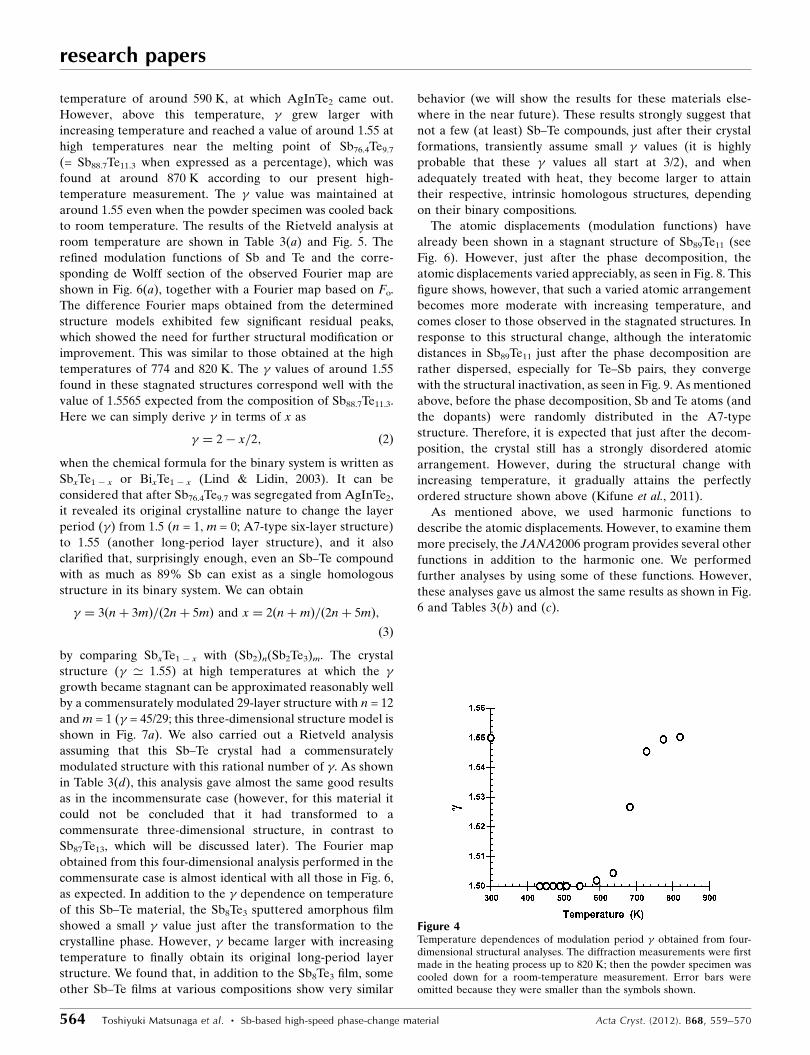
temperature of around 590 K, at which AgInTe2 came out.
However, above this temperature, � grew larger with
increasing temperature and reached a value of around 1.55 at
high temperatures near the melting point of Sb76.4Te9.7
(= Sb88.7Te11.3 when expressed as a percentage), which was
found at around 870 K according to our present high-
temperature measurement. The � value was maintained at
around 1.55 even when the powder specimen was cooled back
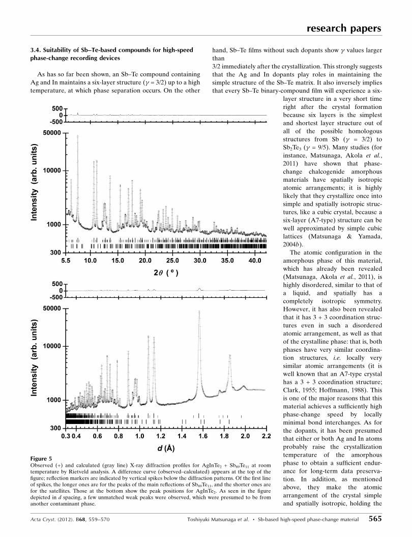
to room temperature. The results of the Rietveld analysis at
room temperature are shown in Table 3(a) and Fig. 5. The
refined modulation functions of Sb and Te and the corre-
sponding de Wolff section of the observed Fourier map are
shown in Fig. 6(a), together with a Fourier map based on Fo.
The difference Fourier maps obtained from the determined
structure models exhibited few significant residual peaks,
which showed the need for further structural modification or
improvement. This was similar to those obtained at the high
temperatures of 774 and 820 K. The � values of around 1.55
found in these stagnated structures correspond well with the
value of 1.5565 expected from the composition of Sb88.7Te11.3.
Here we can simply derive � in terms of x as
� ¼ 2� x=2; ð2Þ
when the chemical formula for the binary system is written as
SbxTe1 � x or BixTe1 � x (Lind & Lidin, 2003). It can be
considered that after Sb76.4Te9.7 was segregated from AgInTe2,
it revealed its original crystalline nature to change the layer
period (�) from 1.5 (n = 1, m = 0; A7-type six-layer structure)
to 1.55 (another long-period layer structure), and it also
clarified that, surprisingly enough, even an Sb–Te compound
with as much as 89% Sb can exist as a single homologous
structure in its binary system. We can obtain
� ¼ 3ðnþ 3mÞ=ð2nþ 5mÞ and x ¼ 2ðnþmÞ=ð2nþ 5mÞ;
ð3Þ
by comparing SbxTe1 � x with (Sb2)n(Sb2Te3)m. The crystal
structure (� ’ 1.55) at high temperatures at which the �growth became stagnant can be approximated reasonably well
by a commensurately modulated 29-layer structure with n = 12
and m = 1 (� = 45/29; this three-dimensional structure model is
shown in Fig. 7a). We also carried out a Rietveld analysis
assuming that this Sb–Te crystal had a commensurately
modulated structure with this rational number of �. As shown
in Table 3(d), this analysis gave almost the same good results
as in the incommensurate case (however, for this material it
could not be concluded that it had transformed to a
commensurate three-dimensional structure, in contrast to
Sb87Te13, which will be discussed later). The Fourier map
obtained from this four-dimensional analysis performed in the
commensurate case is almost identical with all those in Fig. 6,
as expected. In addition to the � dependence on temperature
of this Sb–Te material, the Sb8Te3 sputtered amorphous film
showed a small � value just after the transformation to the
crystalline phase. However, � became larger with increasing
temperature to finally obtain its original long-period layer
structure. We found that, in addition to the Sb8Te3 film, some
other Sb–Te films at various compositions show very similar
behavior (we will show the results for these materials else-
where in the near future). These results strongly suggest that
not a few (at least) Sb–Te compounds, just after their crystal
formations, transiently assume small � values (it is highly
probable that these � values all start at 3/2), and when
adequately treated with heat, they become larger to attain
their respective, intrinsic homologous structures, depending
on their binary compositions.
The atomic displacements (modulation functions) have
already been shown in a stagnant structure of Sb89Te11 (see
Fig. 6). However, just after the phase decomposition, the
atomic displacements varied appreciably, as seen in Fig. 8. This
figure shows, however, that such a varied atomic arrangement
becomes more moderate with increasing temperature, and
comes closer to those observed in the stagnated structures. In
response to this structural change, although the interatomic
distances in Sb89Te11 just after the phase decomposition are
rather dispersed, especially for Te–Sb pairs, they converge
with the structural inactivation, as seen in Fig. 9. As mentioned
above, before the phase decomposition, Sb and Te atoms (and
the dopants) were randomly distributed in the A7-type
structure. Therefore, it is expected that just after the decom-
position, the crystal still has a strongly disordered atomic
arrangement. However, during the structural change with
increasing temperature, it gradually attains the perfectly
ordered structure shown above (Kifune et al., 2011).
As mentioned above, we used harmonic functions to
describe the atomic displacements. However, to examine them
more precisely, the JANA2006 program provides several other
functions in addition to the harmonic one. We performed
further analyses by using some of these functions. However,
these analyses gave us almost the same results as shown in Fig.
6 and Tables 3(b) and (c).
research papers
564 Toshiyuki Matsunaga et al. � Sb-based high-speed phase-change material Acta Cryst. (2012). B68, 559–570
Figure 4Temperature dependences of modulation period � obtained from four-dimensional structural analyses. The diffraction measurements were firstmade in the heating process up to 820 K; then the powder specimen wascooled down for a room-temperature measurement. Error bars wereomitted because they were smaller than the symbols shown.
3.4. Suitability of Sb–Te-based compounds for high-speedphase-change recording devices
As has so far been shown, an Sb–Te compound containing
Ag and In maintains a six-layer structure (� = 3/2) up to a high
temperature, at which phase separation occurs. On the other
hand, Sb–Te films without such dopants show � values larger
than
3/2 immediately after the crystallization. This strongly suggests
that the Ag and In dopants play roles in maintaining the
simple structure of the Sb–Te matrix. It also inversely implies
that every Sb–Te binary-compound film will experience a six-
layer structure in a very short time
right after the crystal formation
because six layers is the simplest
and shortest layer structure out of
all of the possible homologous
structures from Sb (� = 3/2) to
Sb2Te3 (� = 9/5). Many studies (for
instance, Matsunaga, Akola et al.,
2011) have shown that phase-
change chalcogenide amorphous
materials have spatially isotropic
atomic arrangements; it is highly
likely that they crystallize once into
simple and spatially isotropic struc-
tures, like a cubic crystal, because a
six-layer (A7-type) structure can be
well approximated by simple cubic
lattices (Matsunaga & Yamada,
2004b).
The atomic configuration in the
amorphous phase of this material,
which has already been revealed
(Matsunaga, Akola et al., 2011), is
highly disordered, similar to that of
a liquid, and spatially has a
completely isotropic symmetry.
However, it has also been revealed
that it has 3 + 3 coordination struc-
tures even in such a disordered
atomic arrangement, as well as that
of the crystalline phase: that is, both
phases have very similar coordina-
tion structures, i.e. locally very
similar atomic arrangements (it is
well known that an A7-type crystal
has a 3 + 3 coordination structure;
Clark, 1955; Hoffmann, 1988). This
is one of the major reasons that this
material achieves a sufficiently high
phase-change speed by locally
minimal bond interchanges. As for
the dopants, it has been presumed
that either or both Ag and In atoms
probably raise the crystallization
temperature of the amorphous
phase to obtain a sufficient endur-
ance for long-term data preserva-
tion. In addition, as mentioned
above, they make the atomic
arrangement of the crystal simple
and spatially isotropic, holding the
research papers
Acta Cryst. (2012). B68, 559–570 Toshiyuki Matsunaga et al. � Sb-based high-speed phase-change material 565
Figure 5Observed (+) and calculated (gray line) X-ray diffraction profiles for AgInTe2 + Sb89Te11 at roomtemperature by Rietveld analysis. A difference curve (observed–calculated) appears at the top of thefigure; reflection markers are indicated by vertical spikes below the diffraction patterns. Of the first lineof spikes, the longer ones are for the peaks of the main reflections of Sb89Te11, and the shorter ones arefor the satellites. Those at the bottom show the peak positions for AgInTe2. As seen in the figuredepicted in d spacing, a few unmatched weak peaks were observed, which were presumed to be fromanother contaminant phase.
material in a single phase. It is expected that these are indis-
pensable features for high-speed rewritable data storage
media. In the near future, however, the individual roles played
by Ag and In in the phase change of this material should be
clarified.
3.5. Three- or six-layer structure approximation for Sb–Tecompounds
In our previous work (Matsunaga et al., 2001) Sb–Te
compounds with small amounts of Ag or In were concluded to
hold an A7-type structure up to the melting point. However,
we must say that these compounds do not have an exact A7-
type structure but a long-period modulated structure defined
by the binary composition in thermal equilibrium. The A7-
type (six-layer) structure is also one of the modulated struc-
tures (corresponding to the shortest period one). All the
above-mentioned modulated structures can be approximated
by a (cubic stacked) three-layer structure, which provides the
fundamental lines in the diffraction patterns. If atoms at the 6c
site are located at z = 1/4 in the A7-type structure, it corre-
sponds to the three-layer structure. In the previous tempera-
ture measurement, one end of the capillary holding the
powder specimen was open to the
air, which yielded not a little Sb
oxide (Fig. 10). This oxide formed
a line of unnecessary Bragg
peaks, which hindered us from
determining the (weak) satellite
peaks identifying the layer period
of the structure. Further, at that
time, such modulated structures
were not familiarly associated
with the Sb–Te binary system. All
these factors made it difficult for
us to discern that these Sb–Te-
based alloys can take modulated
structures. Thus, in previous work
the A7-type structure was exclu-
sively applied in the structural
analyses, irrespective of the
measurement temperature, which
provided apparently sufficient
results. In addition, in this work
the same structural analysis was
carried out to confirm the repro-
ducibility of the previous work;
we analyzed the structures by
applying this simple 6R structure
to them. The results are shown in
Table 4. As shown in this table,
the R factors were sufficiently low
and the positional parameter z
gradually increased with
temperature (which meant that
the structure model for the Riet-
veld analysis gradually became
research papers
566 Toshiyuki Matsunaga et al. � Sb-based high-speed phase-change material Acta Cryst. (2012). B68, 559–570
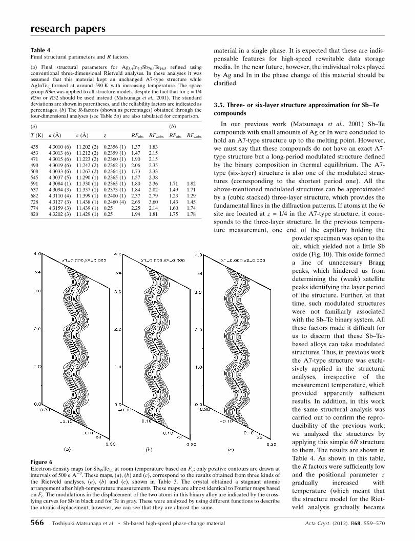
Figure 6Electron-density maps for Sb89Te11 at room temperature based on Fo; only positive contours are drawn atintervals of 500 e A�3. These maps, (a), (b) and (c), correspond to the results obtained from three kinds ofthe Rietveld analyses, (a), (b) and (c), shown in Table 3. The crystal obtained a stagnant atomicarrangement after high-temperature measurements. These maps are almost identical to Fourier maps basedon Fc. The modulations in the displacement of the two atoms in this binary alloy are indicated by the cross-lying curves for Sb in black and for Te in gray. These were analyzed by using different functions to describethe atomic displacement; however, we can see that they are almost the same.
Table 4Final structural parameters and R factors.
(a) Final structural parameters for Ag3.4In3.7Sb76.4Te16.5 refined usingconventional three-dimensional Rietveld analyses. In these analyses it wasassumed that this material kept an unchanged A7-type structure whileAgInTe2 formed at around 590 K with increasing temperature. The spacegroup R�33m was applied to all structure models, despite the fact that for z = 1/4R3m or R32 should be used instead (Matsunaga et al., 2001). The standarddeviations are shown in parentheses, and the reliability factors are indicated aspercentages. (b) The R-factors (shown as percentages) obtained through thefour-dimensional analyses (see Table 5a) are also tabulated for comparison.
(a) (b)
T (K) a (A) c (A) z RFobs RFwobs RFobs RFwobs
435 4.3010 (6) 11.202 (2) 0.2356 (1) 1.37 1.83453 4.3013 (6) 11.212 (2) 0.2359 (1) 1.47 2.15471 4.3015 (6) 11.223 (2) 0.2360 (1) 1.90 2.15490 4.3019 (6) 11.242 (2) 0.2362 (1) 2.06 2.35508 4.3033 (6) 11.267 (2) 0.2364 (1) 1.73 2.33545 4.3037 (5) 11.290 (1) 0.2365 (1) 1.57 2.38591 4.3084 (1) 11.330 (1) 0.2365 (1) 1.80 2.36 1.71 1.82637 4.3094 (3) 11.357 (1) 0.2373 (1) 1.84 2.02 1.49 1.71682 4.3110 (4) 11.399 (1) 0.2400 (1) 2.37 2.79 1.23 1.29728 4.3127 (3) 11.438 (1) 0.2460 (4) 2.65 3.60 1.43 1.45774 4.3159 (3) 11.439 (1) 0.25 2.25 2.14 1.60 1.74820 4.3202 (3) 11.429 (1) 0.25 1.94 1.81 1.75 1.78
closer to the three-layer structure), which accurately repro-
duced the previous results. However, the agreement between
the profiles of the observed and calculated intensities became
worse as the temperature rose, especially for the (weak)
satellite reflections. On the other hand, those obtained
through the four-dimensional analyses showed good agree-
ment with each other, even at high temperatures near the
melting point, as seen in Fig. 10. This strongly indicates that at
high temperatures beyond the phase separation (or in the
thermal equilibrium), this Sb–Te compound is not an A7-type
structure (� = 3/2) itself but one of the homologous structures
defined by � > 3/2.
The present examination clarified that this Sb–Te
compound has a long-period modulated structure like that of
the aforementioned Sb89Te11. The modulation period � kept a
constant value of almost 1.5 up to a temperature of around
600 K, at which the oxidation of Sb started. However, above
this temperature, just as in the Sb89Te11 case, � grew larger
with increasing temperature and reached a value of around
1.56 at high temperatures near the melting point (in contrast,
in the previous experiment, Bragg peaks corresponding to
AgInTe2 were hardly observed for some reason). This � value
indicated that the composition of the compound should be ca
Sb87Te13 [see equation (2)]. Here, we ignore the locations of
Ag and In because they are minor elements. We carried out
research papers
Acta Cryst. (2012). B68, 559–570 Toshiyuki Matsunaga et al. � Sb-based high-speed phase-change material 567
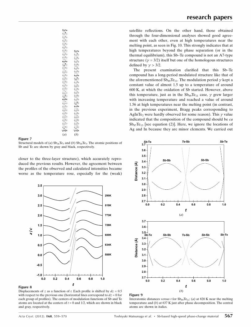
Figure 7Structural models of (a) Sb26Te3 and (b) Sb20Te3. The atomic positions ofSb and Te are shown by gray and black, respectively.
Figure 8Displacements of z as a function of t. Each profile is shifted by dz = 0.5with respect to the previous one (horizontal lines correspond to dz = 0 foreach group of profiles). The centers of modulation functions of Sb and Teatoms are located at the centers of t = 0 and 1/2, which are shown in blackand gray, respectively.
Figure 9Interatomic distances versus t for Sb89Te11: (a) at 820 K near the meltingtemperature and (b) at 637 K just after phase decomposition. The centralatoms are shown in italics.
four-dimensional structural analyses for the two cases where
this Sb–Te crystal took an incommensurately or commensu-
rately modulated structure. As shown in Table 5 these analyses
gave almost the same good results, when � = 36/23 (n = 9, m =
1; Sb87.0Te13.0) was applied in the commensurate case (this
three-dimensional structure model is shown in Fig. 7b).
However, the results of the commensurate case could be
considered somewhat better than those of the incommensu-
rate case (cf. Table 5a with Table 5b1), in contrast to the
examination of Sb89Te11. In addition, we can find a clear t0
dependence of the R values in the results of the Rietveld
analyses performed in the commensurate case (cf. Table 5b1
with Table 5b2). This strongly suggests that this Sb87Te13
compound eventually obtained a (probably stable) commen-
surate structure through rearrangement of the atoms from the
A7-type atomic configuration after sufficient heat treatment
for this material, as observed in the case of Sb8Te3 (Kifune et
al., 2011). Generally, the determination between the
commensurate and incommensurate case seems to be beyond
the information contained in our powder data. However, we
believe that it is very likely that many of these compounds
ultimately obtain commensurate structures after sufficient
heat treatment. We intend to conduct further experiments and
analyses for these materials to reveal their structural features
more precisely.
research papers
568 Toshiyuki Matsunaga et al. � Sb-based high-speed phase-change material Acta Cryst. (2012). B68, 559–570
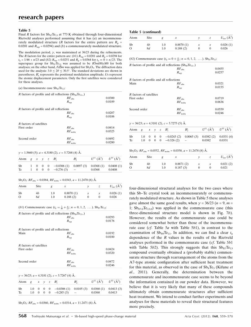
Table 5Final R factors for Sb87Te13 at 773 K obtained through four-dimensionalRietveld analyses performed assuming that it has (a) an incommensu-rately modulated structure (R factors for the entire pattern are Rp =0.0201 and Rwp = 0.0294) and (b) a commensurately modulated structure.
The modulation period, �, was maintained at 36/23 during the refinements.The R factors for the entire pattern are: (b1) Rwp = 0.0201 and Rp = 0.0294 fort0 = 1/46 + n/23 and (b2) Rwp = 0.0251 and Rp = 0.0364 for t0 ¼ 0þ n=23. Thesuperspace group for Sb87Te13 was assumed to be R3m 00�ð Þ00 for bothanalyses; on the other hand, Fd�33m was applied for Sb2O3. The diffraction dataused for the analysis: 3.0 � 2� � 30.5�. The standard deviations are shown inparentheses. Bs
n represents the positional modulation amplitude; Us representthe atomic displacement parameters. Only the first satellites were consideredfor these analyses.
(a) Incommensurate case Sb87Te13:
R factors of profile and all reflections (Sb89Te11+)RFobs 0.0300Rwp 0.0189
R factors of profile and all reflectionsRFobs 0.0207Rwp 0.0106
R factors of satellitesFirst order RFobs 0.0414
RFwobs 0.0325
Second order RFobs 0.0492RFwobs 0.0280
� = 1.5660 (5); a = 4.3180 (2), c = 5.7268 (4) A.
Atom g x y z Bs1 Bs
2 U11 (A2) U33 (A2)
Sb 1 0 0 0 �0.0306 (1) 0.0097 (3) 0.0368 (1) 0.0408 (1)Te 1 0 0 0 �0.276 (3) � 0.0368 0.0408
Sb2O3: RFobs = 0.0384, RFwobs = 0.0343, a = 11.2470 (6) A.
Atom Site g x y z Uiso (A2)
Sb 4b 1.0 0.8870 (1) x x 0.026 (1)O 8d 1.0 0.188 (2) 0 0 0.026
(b1) Commensurate case (t0 ¼146þ
n23 ; n ¼ 0; 1; 2; . . . ). Sb87Te13:
R factors of profile and all reflections (Sb89Te11+)RFobs 0.0293Rwp 0.0176
R factors of profile and all reflectionsMain RFobs 0.0192
Rwp 0.0100
R factors of satellitesFirst order RFobs 0.0424
RFwobs 0.0320
Second order RFobs 0.0472RFwobs 0.0246
� = 36/23; a = 4.3181 (2), c = 5.7267 (4) A.
Atom g x y z Bs1 Bs
2 U11 (A2) U33 (A2)
Sb 1.0 0 0 0 �0.0306 (1) 0.0105 (3) 0.0368 (1) 0.0413 (3)Te 1.0 0 0 0 �0.285 (3) � 0.0368 0.0413
Sb2O3: RFobs = 0.0360, RFwobs = 0.0314, a = 11.2471 (6) A.
Atom Site g x y z Uiso (A2)
Sb 4b 1.0 0.8870 (1) x x 0.026 (1)O 8d 1.0 0.188 (2) 0 0 0.026
(b2) Commensurate case (t0 ¼ 0þ n23 ; n ¼ 0; 1; 2; . . . ). Sb87Te13:
R factors of profile and all reflections (Sb89Te11+)RFobs 0.0455Rwp 0.0257
R factors of profile and all reflectionsMain RFobs 0.0321
Rwp 0.0155
R factors of satellitesFirst order RFobs 0.0719
RFwobs 0.0636
Second order RFobs 0.0559RFwobs 0.0246
� = 36/23; a = 4.3181 (2), c = 5.7275 (5) A.
Atom g x y z Bs1 Bs
2 U11 (A2) U33 (A2)
Sb 1.0 0 0 0 �0.0243 (2) 0.0065 (3) 0.0382 (2) 0.0331 (4)Te 1.0 0 0 0 �0.326 (2) – 0.0382 0.0331
Sb2O3: RFobs = 0.0552, RFwobs = 0.0358, a = 11.2478 (8) A.
Atom Site g x y z Uiso (A2)
Sb 4b 1.0 0.8871 (2) x x 0.021 (2)O 8d 1.0 0.187 (3) 0 0 0.021
Table 5 (continued)
4. Conclusions
An Ag3.4In3.7Sb76.4Te16.5 quaternary amorphous film was first
crystallized into an A7-type structure, in which the four types
of atoms randomly occupied the atomic sites, right after the
phase transformation. However, as the temperature was
raised, this single crystalline phase separated into two crys-
talline phases, AgInTe2 and an Sb–Te binary compound. Of
these two crystals, AgInTe2 was stable up to the melting point.
In contrast, the latter crystal, Sb89Te11, had a modulated layer
structure, and its modulation vector grew with an increasing in
temperature.
The synchrotron radiation experiments were performed on
BL02B2 at SPring-8 with the approval of the Japan Synchro-
tron Radiation Research Institute (proposal Nos. 2010B0084,
2010B1827 and 2011B0030. We express our sincere gratitude
to Dr J. Kim at JASRI and to graduate students K. Shakudo, Y.
Sato and T. Tachizawa of the Graduate School of Science at
Osaka Prefecture University for their assistance with the
experiments. The structural models in Fig. 7 were displayed
using the Java Structure Viewer (JSV 1.08 lite) created by Dr
Steffen Weber.
References
Clark, G. L. (1955). Applied X-rays. New York: McGraw-Hill.Dusek, M., Petrıcek, V. & Palatinus, L. (2010). J. Phys. 226, 012014.
Hoffmann, R. (1988). Solids andSurfaces. New York: VCHPublishers.
Iwasaki, H., Ide, Y., Harigaya, M.,Kageyama, Y. & Fujimura, I. (1992).Jpn. J. Appl. Phys. 31, 461–465.
Karpinsky, O. G., Shelimova, L. E.,Kretova, M. A. & Fleurial, J.-P.(1998). J. Alloys Compd. 268, 112–117.
Kifune, K., Fujita, T., Kubota, Y.,Yamada, N. & Matsunaga, T.(2011). Acta Cryst. B67, 381–385.
Kifune, K., Kubota, Y., Matsunaga, T.& Yamada, N. (2005). Acta Cryst.B61, 492–497.
Kuznetsova, L. A., Kuznetsov, V. L. &Rowe, D. M. (2000). J. Phys. Chem.Solids, 61, 1269–1274.
Lind, H. & Lidin, S. (2003). Solid StateSci. 5, 47–57.
Matsunaga, T., Akola, J., Kohara, S.,Honma, T., Kobayashi, K., Ikenaga,E., Jones, R. O., Yamada, N., Takata,M. & Kojima, R. (2011). Nat. Mater.10, 129–134.
Matsunaga, T., Kojima, R., Yamada,N., Fujita, T., Kifune, K., Kubota, Y.& Takata, M. (2010). Acta Cryst.B66, 407–411.
Matsunaga, T., Kojima, R., Yamada,N., Kifune, K., Kubota, Y., Tabata,Y. & Takata, M. (2006). Inorg.Chem. 45, 2235–2241.
Matsunaga, T., Kojima, R., Yamada,N., Kifune, K., Kubota, Y. & Takata,
M. (2007a). Appl. Phys. Lett. 90, 161919-1–3.Matsunaga, T., Kojima, R., Yamada, N., Kifune, K., Kubota, Y. &
Takata, M. (2007b). Acta Cryst. B63, 346–352.Matsunaga, T., Kojima, R., Yamada, N., Kifune, K., Kubota, Y. &
Takata, M. (2008). Chem. Mater. 20, 5750–5755.Matsunaga, T., Morita, H., Kojima, R., Yamada, N., Kifune, K.,
Kubota, Y., Tabata, Y., Kim, J.-J., Kobata, M., Ikenaga, E. &Kobayashi, K. (2008). J. Appl. Phys. 103, 093511-1–9.
Matsunaga, T., Umetani, Y. & Yamada, N. (2001). Phys. Rev. B, 64,184116-1–7.
Matsunaga, T. & Yamada, N. (2004a). Phys. Rev. B, 69, 104111-1–8.Matsunaga, T. & Yamada, N. (2004b). Jpn. J. Appl. Phys. 43, 4704–
4712.Matsunaga, T., Yamada, N., Kojima, R., Shamoto, S., Sato, M., Tanida,
H., Uruga, T., Kohara, S., Takata, M., Zalden, P., Bruns, G.,Sergueev, I., Wille, H. C., Hermann, R. P. & Wuttig, M. (2011). Adv.Funct. Mater. 21, 2232–2239.
Matsunaga, T., Yamada, N. & Kubota, Y. (2004). Acta Cryst. B60,685–691.
Nishibori, E., Takata, M., Kato, K., Sakata, M., Kubota, Y., Aoyagi, S.,Kuroiwa, Y., Yamakata, M. & Ikeda, N. (2001). Nucl. Instrum.Methods A, 467–468, 1045–1048.
Petrıcek, V. & Dusek, M. (2000). JANA2000. Institute of Physics,Praha, Czech Republic.
Petrıcek, V., Dusek, M. & Palatinus, L. (2006). JANA2006. Instituteof Physics, Praha, Czech Republic.
Poudeu, P. F. P. & Kanatzidis, M. G. (2005). Chem. Commun. pp.2672–2674.
Rietveld, H. M. (1969). J. Appl. Cryst. 2, 65–71.Shelimova, L. E., Karpinskii, O. G., Konstantinov, P. P., Avilov, E. S.,
Kretova, M. A. & Zemskov, V. S. (2004). Inorg. Mater. 40, 530–540.
research papers
Acta Cryst. (2012). B68, 559–570 Toshiyuki Matsunaga et al. � Sb-based high-speed phase-change material 569
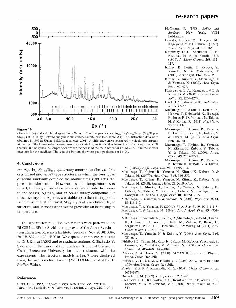
Figure 10Observed (+) and calculated (gray line) X-ray diffraction profiles for Ag3.4In3.7Sb76.4Te16.5 (Sb87Te13 +Sb2O3) at 873 K by Rietveld analysis in the commensurate case (see Table 5b1). This diffraction data wereobtained in 1999 at SPring-8 (Matsunaga et al., 2001). A difference curve (observed � calculated) appearsat the top of the figure; reflection markers are indicated by vertical spikes below the diffraction patterns. Ofthe first line of spikes the longer ones are for the peaks of the main reflections of Sb87Te13, and the shorterones are for the satellites. Those at the bottom show the peak positions for Sb2O3.

Shelimova, L. E., Karpinskii, O. G., Konstantinov, P. P., Kretova,M. A., Avilov, E. S. & Zemskov, V. S. (2001). Inorg. Mater. 37, 342–348.
Shelimova, L. E., Karpinskii, O. G., Zemskov, V. S. & Konstantinov,P. P. (2000). Inorg. Mater. 36, 235–242.
Shelimova, L. E., Konstantinov, P. P., Karpinsky, O. G., Avilov, E. S.,Kretova, M. A. & Zemskov, V. S. (2001). J. Alloys Compd. 329, 50–62.
Wolff, P. M. de (1974). Acta Cryst. A30, 777–785.Wolff, P. M. de, Janssen, T. & Janner, A. (1981). Acta Cryst. A37, 625–
636.Wuttig, M. & Yamada, N. (2007). Nat. Mater. 6, 824–832.Wyckoff, R. W. G. (1986). Crystal Structures, Vol. 2. Florida: Robert
E. Krieger Publishing Company.Yamada, N., Ohno, E., Nishiuchi, K., Akahira, N. & Takao, M. (1991).
J. Appl. Phys. 69, 2849–2856.
research papers
570 Toshiyuki Matsunaga et al. � Sb-based high-speed phase-change material Acta Cryst. (2012). B68, 559–570