Embed Size (px)
Citation preview
Seediscussions,stats,andauthorprofilesforthispublicationat:https://www.researchgate.net/publication/258358581
Structuralresponseofinterlockingcompositemasonryslab
ArticleinICEProceedingsStructuresandBuildings·March2011
CITATIONS
0
READS
30
1author:
Someoftheauthorsofthispublicationarealsoworkingontheserelatedprojects:
StructuralandMaterialAssessmentofHistoricalStructure,ManahTownViewproject
YavuzYardim
UniversityofNizwa
48PUBLICATIONS72CITATIONS
SEEPROFILE
AllcontentfollowingthispagewasuploadedbyYavuzYardimon03November2015.
Theuserhasrequestedenhancementofthedownloadedfile.Allin-textreferencesunderlinedinblueareaddedtotheoriginaldocument
andarelinkedtopublicationsonResearchGate,lettingyouaccessandreadthemimmediately.

Proceedings of the Institution of Civil Engineers
Structures and Buildings 164 December 2011 Issue SB6
Pages 409–420 http://dx.doi.org/10.1680/stbu.2011.164.6.409
Paper 700028
Received 27/06/2007 Accepted 08/03/2011
Keywords: buildings, structures & design/composite structures/failures
ICE Publishing: All rights reserved
Structures and BuildingsVolume 164 Issue SB6
Structural response of interlockingcomposite masonry slabThanoon, Yardim, Jaafar and Noorzaei
Structural response ofinterlocking compositemasonry slabj1 Waleed A. Thanoon PhD
Professor & Dean, College of Engineering and Architecture,University of Nizwa, Sultanate of Oman
j2 Yavuz Yardim PhDAssistant Professor, Engineering Faculty, Epoka University, Albania
j3 Mohd Saleh Jaafar PhDProfessor, Faculty of Engineering, University Putra Malaysia,Selangor, Malaysia
j4 Jamaloddin Noorzaei PhDProfessor, Faculty of Engineering, University Putra Malaysia,Malaysia
j1 j2 j3 j4
This study introduces a semi-fabricated composite floor slab system that consists of a precast inverted ribbed
ferrocement panel interlocked in situ with a brick–rib layer to form a composite slab. The effectiveness of the
interlocking mechanism of the composite slab was investigated under separate shear and flexural loadings. Ten
composite slab specimens having different shear connectivity between the two layers were cast and tested under
pure shear loading (push-off test). Six further slab specimens were cast and tested under two line loadings to explore
the structural response of the composite slab system under flexural loading. The flexural tests focused on the effect
of different brick layouts and orientation and thus different numbers of interlocking ribs in longitudinal and
transverse directions on the overall structural response of the composite slab. The results of push-off tests indicate
that the proposed interlocking system is as effective as using steel truss shear connectors in composite slabs. The
flexural test results in terms of load–deflection, crack pattern, ductility and failure loads indicate that the response of
the composite slab to flexural loading is satisfactory for use as a structural floor slab.
1. IntroductionReinforced concrete (RC) slabs are widely used in construction
because of their low cost, good performance and durability.
However, the cost of the formwork is high, ranging from 30 to
100% of the cost of the structure, depending on shape, size and
finishing requirements (Razali et al., 1993). In addition, the self-
weight of the concrete induces a high dead load on walls,
columns and beams.
Prefabricated floors are used in many parts of the world as an
alternative system to overcome formwork problems (cost and
delays in construction) and to control the quality of concrete.
However, prefabricated elements are very heavy and difficult to
transport and construct. In addition, concrete does not provide the
thermal insulation qualities desired for living accommodation.
Jointing connectivity is another problem observed in precast
construction, which leads to a less integrated structure.
To overcome these deficiencies, a large number of precast
systems have been developed. Pessiki et al. (1995) summarised
the use of 19 different precast structural floor systems that are
suitable for office building construction in different parts of the
world. Thin ferrocement panels have been used in floor construc-
tion for low-cost housing (Mansur and Ong, 1986; Omorodion-
Ikhimwin, 1983) due to their low cost and good structural
performance. The introduction of insulating sandwich panels has
increased the attractiveness of this type of construction. The
panels consist of thin layers of relatively higher strength material
sandwiching a thick core, normally of much weaker and lower
density material (Einea et al., 1994; Wright et al., 1987).
However, the high manufacturing and construction costs limit the
use of precast sandwich panels in construction. The use of
profiled steel sheeting as an integral part of RC deck slabs has
gained wide acceptance in many countries, especially those where
the cost of profiled steel sheeting is low (Kim and Youn, 2009;
Redzuan and Samuel, 2009). Such composite systems have been
used in bridges and long-span structures. The ultimate load
capacity of the profiled sheeting–concrete composite depends on
the shear bond characteristic and the slenderness parameters of
the profiled sheeting (Salmon et al., 1997). Cost and thermal
409

efficiency are some of the limitations of these systems. Profiled
sheeting–cement board composites, another recent development
in floor slab systems (Ahmed et al., 2002; Wan Badaruzzaman et
al., 2003), consist of profiled sheeting attached to a top layer of
dry board by simple mechanical connectors. Lightweight concrete
is used as an infill material to act as a sound insulator for the
floor. However, one of the limitations of this system is its low
stiffness, which results in large deflections and the development
of cracks in the finishing elements connected to the slab.
A semi-precast system known in Malaysia as a ‘half slab’ is
another development in floor slab construction (Yee, 2001a,
2001b). The technique employs a reinforced precast floor panel
that serves as permanent formwork for the composite with cast-
in-situ concrete. Steel lattice trusses projecting from the top of
the precast unit (Figure 1) are used to connect the two layers and
make the unit stiff during erection. The heavy weight of the full
slab, its low thermal efficiency and the additional cost of the steel
trusses needed to connect the two layers are some of the
disadvantages of the system.
Developing a new floor slab system to overcome the short-
comings of in situ concrete floor slabs and existing precast floor
systems is a challenging task for many researchers. Existing
systems have shortcomings such as long construction time, heavy
weight, dependency on heavy equipment at the job site, poor
thermal and sound insulation, high material wastage, dependency
on formwork, lack of structural integrity, jointing problems and
high cost.
This study introduces a semi-precast floor slab system, a
ferrocement–brick composite slab, to address some of the above
problems and to address the longitudinal shear failure commonly
observed in other composite slab systems (Thanoon et al.,
2010). The paper investigates the structural performance of the
ferrocement–brick composite slab under pure shear and flexural
short-term loadings. The main objective of the experimental
programme was to explore the efficiency of the proposed
interlocking system in connecting the two layers of the compo-
site. The deformational characteristics, ductility, ultimate
moment capacity and failure mechanism of the composite slab
are also presented and discussed.
2. Proposed ferrocement–brick compositesystem
The proposed floor slab is a semi-precast system that consists of
a precast inverted ribbed ferrocement panel (Figure 2(a)). This
layer provides a formwork for the bricks and cast-in-situ ribs.
Bricks are then laid in position (without the use of mortar) as
shown in Figure 2(b). The composite floor system is completed
by filling the in situ grooves between the bricks; these form the in
situ ribs as shown in Figure 2(c). Interlocking between the bricks,
the precast layer and the cast-in-situ ribs provides the necessary
shear transfer developed due to bending of the composite slab
(Figure 2(d)). The proposed interlocking concept does not require
any shear reinforcement (links or trusses) commonly used to
resist horizontal shear between two composite layers.
The precast ferrocement layer consists of wire mesh and steel
reinforcement to resist the flexural tensile stresses developed
during load transfer to the supporting beams or walls. The
thickness and reinforcement of this layer will mainly depend on
the span of the slab. The bricks and the in situ ribs provide the
necessary resistance to bear flexural compressive stresses.
One advantage of this system is that it is relatively light in weight
compared with an RC solid slab, which reduces the load
transferred to beams/walls. The masonry bricks act as a light
(especially voided brick), natural, cheap and effective insulation
material at the same time as partially resisting compression forces
developed due to bending of the composite.
On-site construction of the composite slab does not require any
heavy equipment to handle the ferrocement layer. Furthermore,
the construction does not require any formwork since the bottom
layer of the ferrocement is a precast unit that can be easily fixed
in position, using a simple crane, to provide a platform that acts
600 mm centre to centre
50–100 mm600/1200/1800/2400 mm
Figure 1. Half slab floor system
(a) Ferrocement precast layer
(b) Bricks laid in position
In situ ribs
(c) Ferrocement–brick composite floor
(d) Interlocked composite floor
Figure 2. Interlocking ferrocement–brick composite floor slab
410
Structures and BuildingsVolume 164 Issue SB6
Structural response of interlockingcomposite masonry slabThanoon, Yardim, Jaafar and Noorzaei

as a formwork for the brick layer and the concrete ribs. The cold
joint problem usually observed in precast construction can also
be eliminated with this system. The floor slab units and support-
ing beams (or other slab units) will be integrated during casting
of the in situ concrete ribs.
3. Experimental programme
3.1 Test specimens
The effectiveness of the interlocking mechanism in transferring
shear stresses was initially investigated. Ten composite slab
specimens (750 mm 3 928 mm) with different shear connectiv-
ities between the two layers were cast and tested under pure shear
loading (push-off testing). The length of the specimens was
selected to account for brick–rib interaction. The specimens were
categorised into three types according to the way in which the
two layers were interconnected
(a) plain (P) specimens had no connectors between the two layers
(b) shear truss connectors were used to connect the two layers in
specimens of the second type (S specimens)
(c) the third type used an interlocking groove to connect the
layers (I specimens).
Specimens of the third type (interlocking system) were further
subdivided into groups IA, IB and IC to simulate different
interlocking depths by varying the depth of the precast and in situ
ribs. The depths of the interlocking grooves (precast ribs) were
fixed at 40, 30 and 20 mm respectively for specimens IA, IB and
IC (Figure 3).
The effectiveness of the proposed interlocking system in resisting
shear was explored by comparing the shear resistance of the
interlocked specimens with that of the specimens with steel truss
shear connectors. The shear connector used in S specimens was a
continuous steel truss placed at 250 mm centre to centre. The
truss members were made of 6 mm diameter mild steel bar of
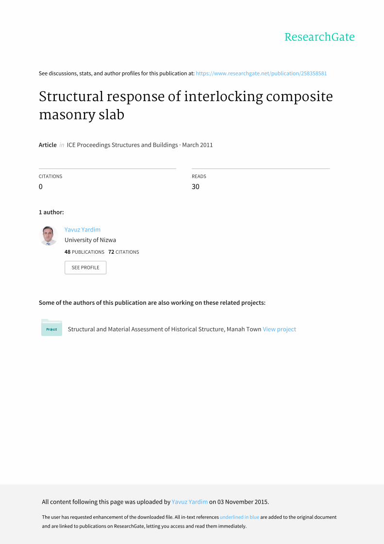
depth 50 mm as shown in Figure 4.
The flexural response of the composite slab was investigated by
testing six slab specimens, each 1.5 m long, 0.75 m wide and
0.95 m thick. The specimens were tested under two-line loading.
The tests focused on the structural response of slabs with differ-
ent interlocking ribs as a result of different brick layouts. The
specimens were arranged in three groups (A, B and C), with each
group having two identical specimens. The brick arrangements of
each group are shown in Figure 5. In all the specimens, the depth
of the ferrocement layer (including rib depth) was 60 mm; this
was reinforced with two layers of 1.2 mm diameter wire mesh of
12.7 mm 3 12.7 mm opening and 4T10 mm diameter steel rein-
forcement. The hollow brick layer was 65 mm thick (brick size
216 3 100 3 65 mm). The surface areas and volumes of the
70 215 70 215 70 215 70
50
50
50
AA
100
750
Plan
In situ ribs
Bricks Bricks Bricks
Ferrocement precast layer
110 mm
45 mm
Variable 25, 35, 45 mm
Interlocking depth,variable 40, 30, 20 mm
Section A–A for interlocking group
Figure 3. Plan and cross-section details for tested specimens
(dimensions in millimetres)
411
Structures and BuildingsVolume 164 Issue SB6
Structural response of interlockingcomposite masonry slabThanoon, Yardim, Jaafar and Noorzaei
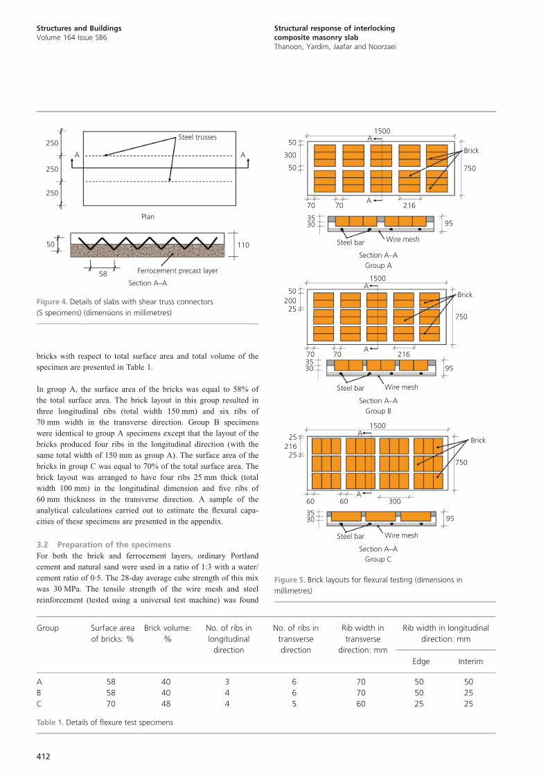
bricks with respect to total surface area and total volume of the
specimen are presented in Table 1.
In group A, the surface area of the bricks was equal to 58% of
the total surface area. The brick layout in this group resulted in
three longitudinal ribs (total width 150 mm) and six ribs of
70 mm width in the transverse direction. Group B specimens
were identical to group A specimens except that the layout of the
bricks produced four ribs in the longitudinal direction (with the
same total width of 150 mm as group A). The surface area of the
bricks in group C was equal to 70% of the total surface area. The
brick layout was arranged to have four ribs 25 mm thick (total
width 100 mm) in the longitudinal dimension and five ribs of
60 mm thickness in the transverse direction. A sample of the
analytical calculations carried out to estimate the flexural capa-
cities of these specimens are presented in the appendix.
3.2 Preparation of the specimens
For both the brick and ferrocement layers, ordinary Portland
cement and natural sand were used in a ratio of 1:3 with a water/
cement ratio of 0.5. The 28-day average cube strength of this mix
was 30 MPa. The tensile strength of the wire mesh and steel
reinforcement (tested using a universal test machine) was found
Steel trusses
AA
250
250
250
Plan
50
58
110
Ferrocement precast layer
Section A–A
Figure 4. Details of slabs with shear truss connectors
(S specimens) (dimensions in millimetres)
Section A–AGroup B
50200
25
1500A
Brick
750
70 70A
216
953530
Steel bar Wire mesh
Section A–AGroup A
50
300
50
1500A
Brick
750
70 70A
216
953530
Steel bar Wire mesh
Section A–AGroup C
25216
25
1500A
Brick
750
60 60A
300
953530
Steel bar Wire mesh
Figure 5. Brick layouts for flexural testing (dimensions in
millimetres)
Group Surface area
of bricks: %
Brick volume:
%
No. of ribs in
longitudinal
direction
No. of ribs in
transverse
direction
Rib width in
transverse
direction: mm
Rib width in longitudinal
direction: mm
Edge Interim
A 58 40 3 6 70 50 50
B 58 40 4 6 70 50 25
C 70 48 4 5 60 25 25
Table 1. Details of flexure test specimens
412
Structures and BuildingsVolume 164 Issue SB6
Structural response of interlockingcomposite masonry slabThanoon, Yardim, Jaafar and Noorzaei
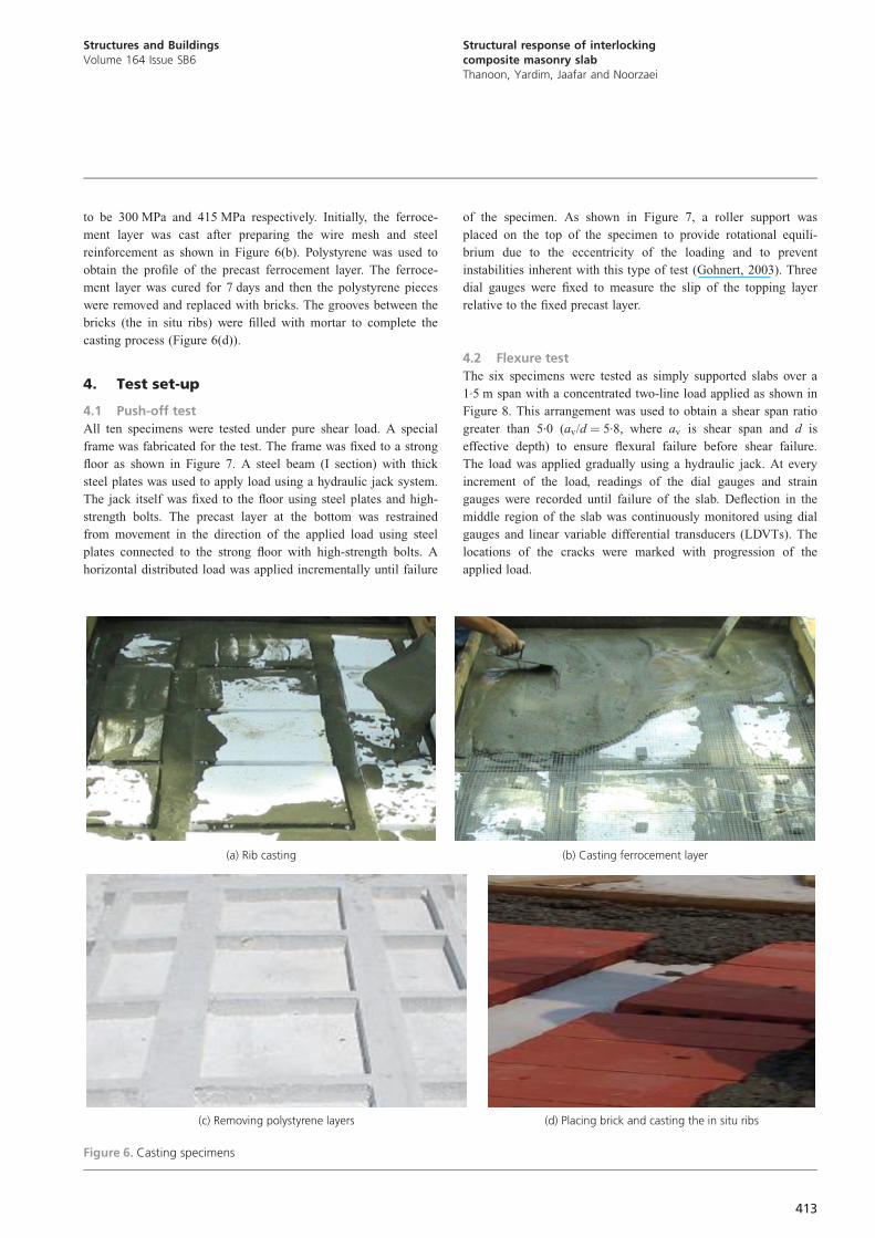
to be 300 MPa and 415 MPa respectively. Initially, the ferroce-
ment layer was cast after preparing the wire mesh and steel
reinforcement as shown in Figure 6(b). Polystyrene was used to
obtain the profile of the precast ferrocement layer. The ferroce-
ment layer was cured for 7 days and then the polystyrene pieces
were removed and replaced with bricks. The grooves between the
bricks (the in situ ribs) were filled with mortar to complete the
casting process (Figure 6(d)).
4. Test set-up
4.1 Push-off test
All ten specimens were tested under pure shear load. A special
frame was fabricated for the test. The frame was fixed to a strong
floor as shown in Figure 7. A steel beam (I section) with thick
steel plates was used to apply load using a hydraulic jack system.
The jack itself was fixed to the floor using steel plates and high-
strength bolts. The precast layer at the bottom was restrained
from movement in the direction of the applied load using steel
plates connected to the strong floor with high-strength bolts. A
horizontal distributed load was applied incrementally until failure
of the specimen. As shown in Figure 7, a roller support was
placed on the top of the specimen to provide rotational equili-
brium due to the eccentricity of the loading and to prevent
instabilities inherent with this type of test (Gohnert, 2003). Three
dial gauges were fixed to measure the slip of the topping layer
relative to the fixed precast layer.
4.2 Flexure test
The six specimens were tested as simply supported slabs over a
1.5 m span with a concentrated two-line load applied as shown in
Figure 8. This arrangement was used to obtain a shear span ratio
greater than 5.0 (av/d ¼ 5.8, where av is shear span and d is
effective depth) to ensure flexural failure before shear failure.
The load was applied gradually using a hydraulic jack. At every
increment of the load, readings of the dial gauges and strain
gauges were recorded until failure of the slab. Deflection in the
middle region of the slab was continuously monitored using dial
gauges and linear variable differential transducers (LDVTs). The
locations of the cracks were marked with progression of the
applied load.
(a) Rib casting (b) Casting ferrocement layer
(c) Removing polystyrene layers (d) Placing brick and casting the in situ ribs
Figure 6. Casting specimens
413
Structures and BuildingsVolume 164 Issue SB6
Structural response of interlockingcomposite masonry slabThanoon, Yardim, Jaafar and Noorzaei

5. Results and discussion
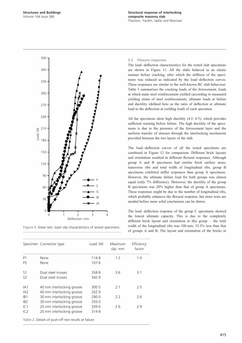
5.1 Shear test
Figure 9 shows the relation between applied shear load and slip
between the two layers of the composite slab. A very small slip
(1–2 mm) was observed in all the tested specimens apart from
those with steel truss shear connectors (S specimens). In general,
the load–slip characteristics of S specimens and I specimens
were similar, and also quite similar to those reported by Moy and
Tayler (1996) and Gohnert (2000). Before failure there was a
sudden increase in the slip followed by a brittle type of failure.
The maximum slip and failure loads of all the specimens are
listed in Table 2. The efficiency factors – defined as the ratio of
experimental ultimate shear load of specimens with shear con-
nectors to that of specimens without any shear connectors – were
calculated and are also shown in the Table 2. The efficiency
factor of specimens with dual steel truss shear connectors was 3.1
and the specimens with the proposed interlocking system showed
comparable results with efficiency factors of 2.5–2.9 (average
2.75). This indicates that the proposed interlocking mechanism is
as effective as steel trusses in resisting shear stresses and could
thus be used to replace steel trusses with consequent reductions
in cost.
For specimens without a shear connector, failure was sudden and
without any signs of cracking (Figure 10a). The in situ topping
layer slid on the precast layer when the shear stress equalled
0.17 MPa. Specimens with dual shear truss connectors showed a
longitudinal crack along the steel truss (Figure 10(b)) at a load
equal to 90% of the failure load. The crack width increased with
increases in applied load until the mortar crushed around the
trusses without failure of the steels.
The interlocking group of specimens failed by shearing off of the
interlocking ribs as shown in Figures 10(c) and 10(d). However,
one specimen suffered a bearing failure in the rib at the vicinity
of the applied load (Figure 10(e)). All the specimens showed
brittle type of failure. However, the specimens with steel truss
shear connectors showed much higher slips and cracks before
their sudden failure.
Load
Interlock depth
Reaction
Fix
Figure 7. Pure shear test set-up
Hydraulic jack
I beam
545 mm 310 mm 545 mmL 1500 mm�
Two-line load test (flexural test)
Figure 8. Flexure test set-up
414
Structures and BuildingsVolume 164 Issue SB6
Structural response of interlockingcomposite masonry slabThanoon, Yardim, Jaafar and Noorzaei
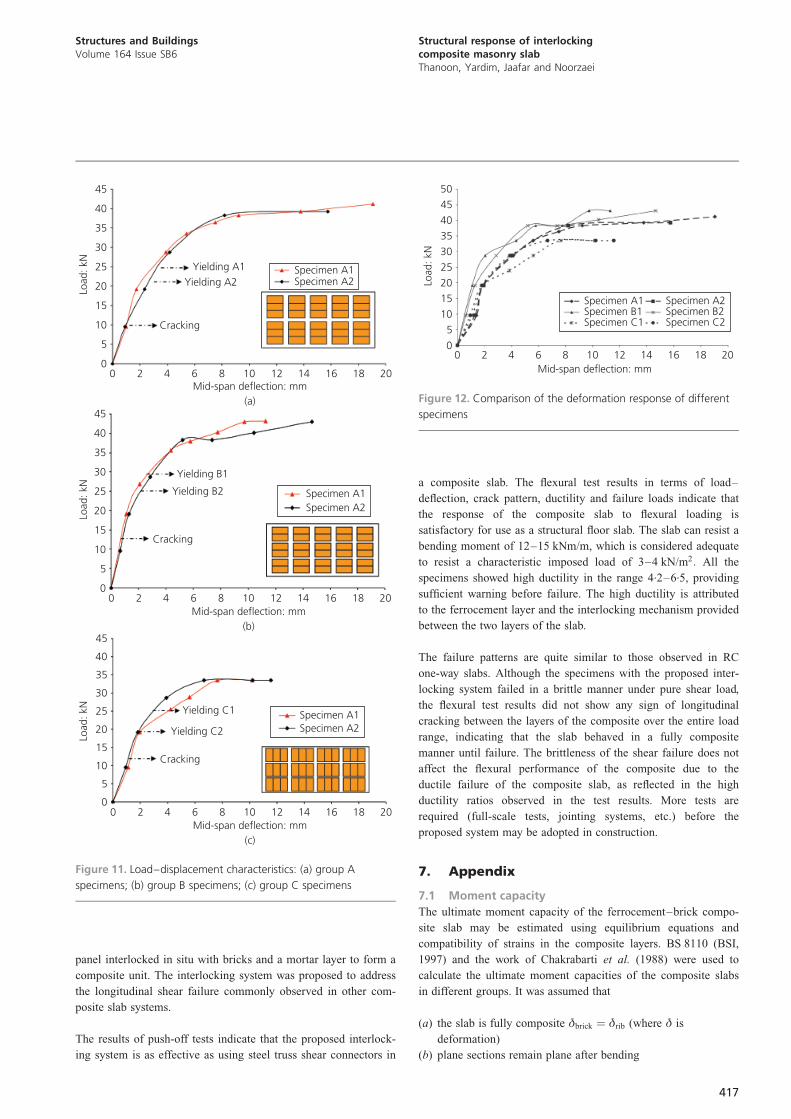
5.2 Flexure response
The load–deflection characteristics for the tested slab specimens
are shown in Figure 11. All the slabs behaved in an elastic
manner before cracking, after which the stiffness of the speci-
mens was reduced as indicated by the load–deflection curves.
These responses are similar to the well-known RC slab behaviour.
Table 3 summarises the cracking loads of the ferrocement, loads
at which main steel reinforcement yielded (according to measured
yielding strain of steel reinforcement), ultimate loads at failure
and ductility (defined here as the ratio of deflection at ultimate
load to the deflection at yielding load) of each specimen.
All the specimens show high ductility (4.2–6.5), which provides
sufficient warning before failure. The high ductility of the speci-
mens is due to the presence of the ferrocement layer and the
uniform transfer of stresses through the interlocking mechanism
provided between the two layers of the slab.
The load–deflection curves of all the tested specimens are
combined in Figure 12 for comparison. Different brick layouts
and orientation resulted in different flexural responses. Although
group A and B specimens had similar brick surface areas,
transverse ribs and total width of longitudinal ribs, group B
specimens exhibited stiffer responses than group A specimens.
However, the ultimate failure load for both groups was almost
equal (only 7% difference). Moreover, the ductility of the group
B specimens was 20% higher than that of group A specimens.
These responses might be due to the number of longitudinal ribs,
which probably enhances the flexural response, but more tests are
needed before more solid conclusions can be drawn.
The load–deflection response of the group C specimens showed
the lowest ultimate capacity. This is due to the completely
different brick layout and orientation in this group – the total
width of the longitudinal ribs was 100 mm, 33.3% less than that
of groups A and B. The layout and orientation of the bricks in
390
360
330
300
270
240
210
180
150
120
90
60
30
00 1 2 3 4
Deflection: mm
Load
: kN
P
S
IC
IB
IA
Figure 9. Shear test: load–slip characteristics of tested specimens
Specimen Connector type Load: kN Maximum
slip: mm
Efficiency
factor
P1 None 114.8 1.2 1.0
P2 None 107.6
S1 Dual steel trusses 358.8 3.6 3.1
S2 Dual steel trusses 342.9
IA1 40 mm interlocking groove 300.5 2.1 2.5
IA2 40 mm interlocking groove 262.9
IB1 30 mm interlocking groove 290.0 2.2 2.6
IB2 30 mm interlocking groove 293.0
IC1 20 mm interlocking groove 339.0 2.6 2.9
IC2 20 mm interlocking groove 314.8
Table 2. Details of push-off test results at failure
415
Structures and BuildingsVolume 164 Issue SB6
Structural response of interlockingcomposite masonry slabThanoon, Yardim, Jaafar and Noorzaei

this group reduced both the number and size of the transverse
ribs. The ultimate capacities of group A and B specimens were
respectively 21% and 29% higher than those of group C.
However, the surface area of the bricks in group C was 20%
higher than the other two groups; this leads to a reduction in
weight of the panel and better thermal properties.
All specimens showed a similar cracking load of 12 kN (about
30% of the ultimate load). The cracks started in the ferrocement
layers and gradually extended upwards with increases in applied
load. The crack patterns of different specimens at failure are
shown in Figure 13. The majority of cracks are concentrated at
the peak moment region. No longitudinal cracks were observed
between the two layers of the slab throughout the entire loading
process, indicating that the slab specimens behaved in a fully
composite manner until failure. Similar failure patterns were
found in all the slab specimens: widening of flexural cracks that,
at the moment of failure, extended upwards before crushing the
top part of the slab at this region as shown in Figure 13. The
widest crack was observed in the group C specimens. The failure
patterns are quite similar to those observed in RC one-way slabs.
The ultimate moments recorded for all specimens are also
presented in Table 3. The values range from 12 to 15 kNm per
metre width of slab, which is considered adequate to resist an
equivalent characteristic uniformly distributed imposed load of
3–4 kN/m2:
The analytical calculations presented in the appendix (BSI, 1997;
Chakrabarti et al., 1988) show that the estimated failure loads for
different slab specimens were 40.7 kN for groups A and B and
40.3 kN for group C. These capacities were calculated without
using material safety factors. The calculations give good esti-
mates for the ultimate load compared with the average ultimate
experimental load found in group A and B specimens. However,
for group C specimens, the analytical calculation gives an
ultimate load 20% higher than that found experimentally. A more
comprehensive method is required to estimate the analytical
capacity of the composite slab.
6. ConclusionThis paper has introduced a semi-fabricated composite system for
a floor slab. It consists of a precast inverted ribbed ferrocement
(a) Type P specimen
(c) Type IC specimen (e) Type IA specimen(d) Type IB specimen
(b) Type S specimen
Figure 10. Failure mechanisms of different specimens in push-off
shear tests
416
Structures and BuildingsVolume 164 Issue SB6
Structural response of interlockingcomposite masonry slabThanoon, Yardim, Jaafar and Noorzaei
panel interlocked in situ with bricks and a mortar layer to form a
composite unit. The interlocking system was proposed to address
the longitudinal shear failure commonly observed in other com-
posite slab systems.
The results of push-off tests indicate that the proposed interlock-
ing system is as effective as using steel truss shear connectors in
a composite slab. The flexural test results in terms of load–
deflection, crack pattern, ductility and failure loads indicate that
the response of the composite slab to flexural loading is
satisfactory for use as a structural floor slab. The slab can resist a
bending moment of 12–15 kNm/m, which is considered adequate
to resist a characteristic imposed load of 3–4 kN/m2: All the
specimens showed high ductility in the range 4.2–6.5, providing
sufficient warning before failure. The high ductility is attributed
to the ferrocement layer and the interlocking mechanism provided
between the two layers of the slab.
The failure patterns are quite similar to those observed in RC
one-way slabs. Although the specimens with the proposed inter-
locking system failed in a brittle manner under pure shear load,
the flexural test results did not show any sign of longitudinal
cracking between the layers of the composite over the entire load
range, indicating that the slab behaved in a fully composite
manner until failure. The brittleness of the shear failure does not
affect the flexural performance of the composite due to the
ductile failure of the composite slab, as reflected in the high
ductility ratios observed in the test results. More tests are
required (full-scale tests, jointing systems, etc.) before the
proposed system may be adopted in construction.
7. Appendix
7.1 Moment capacity
The ultimate moment capacity of the ferrocement–brick compo-
site slab may be estimated using equilibrium equations and
compatibility of strains in the composite layers. BS 8110 (BSI,
1997) and the work of Chakrabarti et al. (1988) were used to
calculate the ultimate moment capacities of the composite slabs
in different groups. It was assumed that
(a) the slab is fully composite �brick ¼ �rib (where � is
deformation)
(b) plane sections remain plane after bending
45
40
35
30
25
20
15
10
5
0
Load
: kN
0 2 4 6 8 10 12 14 16 18 20Mid-span deflection: mm
(a)
Specimen A1Specimen A2
Yielding A1Yielding A2
Cracking
45
40
35
30
25
20
15
10
5
0
Load
: kN
0 2 4 6 8 10 12 14 16 18 20Mid-span deflection: mm
(b)
Specimen A1Specimen A2
Yielding B1
Yielding B2
Cracking
45
40
35
30
25
20
15
10
5
0
Load
: kN
0 2 4 6 8 10 12 14 16 18 20Mid-span deflection: mm
(c)
Specimen A1Specimen A2
Yielding C1
Yielding C2
Cracking
Figure 11. Load–displacement characteristics: (a) group A
specimens; (b) group B specimens; (c) group C specimens
50
45
40
35
30
25
20
15
10
5
0
Load
: kN
0 2 4 6 8 10 12 14 16 18 20Mid-span deflection: mm
Specimen A1 Specimen A2Specimen B1 Specimen B2Specimen C1 Specimen C2
Figure 12. Comparison of the deformation response of different
specimens
417
Structures and BuildingsVolume 164 Issue SB6
Structural response of interlockingcomposite masonry slabThanoon, Yardim, Jaafar and Noorzaei

Specimen Cracking
load: kN
Yielding
load: kN
Ultimate
load: kN
Ultimate
moment: kNm
Ductility
�u/�y
A1 12.5 27.4 41.2 11.3 4.75
A2 13.0 24.0 39.3 10.8 5.60
B1 12.5 28.8 43.1 11.75 5.65
B2 12.0 25.0 43.1 11.75 6.70
C1 12.3 19.2 33.5 9.13 5.10
C2 11.5 25.0 33.4 9.1 4.20
Table 3. Details of flexure test results
CL
CL
CL
Crushing
(a)
(b)
(c)
Figure 13. Failure mechanisms of (a) group A, (b) group B and
(c) group C specimens
418
Structures and BuildingsVolume 164 Issue SB6
Structural response of interlockingcomposite masonry slabThanoon, Yardim, Jaafar and Noorzaei
(c) the effect of the transverse ribs in stiffening the longitudinal
ribs can be ignored.
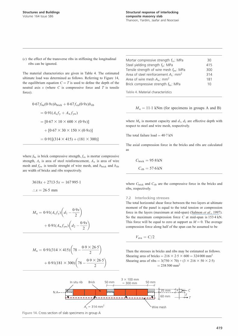
The material characteristics are given in Table 4. The estimated
ultimate load was determined as follows. Referring to Figure 14,
the equilibrium equation C ¼ T is used to define the depth of the
neutral axis x (where C is compressive force and T is tensile
force).
0:67 fbu(0:9x)bbrick þ 0:67 f cu(0:9x)brib
¼ 0:91(As f y þ Aw fyw)
¼ [0:673 103 6003 (0:9x)]
þ [0:673 303 1503 (0:9x)]
¼ 0:91[(3143 415)þ (1813 300)]
where fbu is brick compressive strength, fcu is mortar compressive
strength, As is area of steel reinformcement, Aw is area of wire
mesh and fyw is tensile strenght of wire mesh, and bbrick and brib
are width of bricks and ribs respectively.
3618xþ 2713:5x ¼ 167 995:1
\x ¼ 26:5 mm
Mu ¼ 0:91(As f y) d1 �0:9x
2
� �
þ 0:91(Aw f yw) d2 �0:9x
2
� �
Mu ¼ 0:91(3143 415) 78� 0:93 26:5
2
� �
þ 0:91(1813 300) 78� 0:93 26:5
2
� �
Mu ¼ 11:1 kNm (for specimens in groups A and B)
where Mu is moment capacity and d1, d2 are effective depth with
respect to steel and wire mesh, respectively.
The total failure load ¼ 40.7 kN
The axial compression force in the bricks and ribs are calculated
as
Cbrick ¼ 95:8 kN
Crib ¼ 57:6 kN
where Cbrick and Crib are the compressive force in the bricks and
ribs, respectively.
7.2 Interlocking stresses
The total horizontal shear force between the two layers at ultimate
moment of the panel is equal to the total tension or compression
force in the layers (maximum at mid-span) (Salmon et al., 1997).
So the maximum compression force C at mid-span is 153.4 kN.
This force will be equal to zero at support as M ¼ 0. The average
compression force along half of the span can be assumed to be
Vava ¼ C=2
Then the stresses in bricks and ribs may be estimated as follows.
Shearing area of bricks ¼ 2163 2.53 600 ¼ 324 000 mm2
Shearing area of ribs ¼ 3(750 3 70) + (3 3 216 3 50 3 2.5)
¼ 238 500 mm2
Mortar compressive strength fcu: MPa 30
Steel yielding strength fys: MPa 415
Tensile strength of wire mesh fyw: MPa 300
Area of steel reinforcement As: mm2 314
Area of wire mesh Aw: mm2 181
Brick compressive strength fbu: MPa 10
Table 4. Material characteristics
Brick
Wire meshAs2314 mm�
x C
T
35 mm
60 mmN.A
z
50 mm3 100 mm
300 mm�
�50 mmIn situ rib
Figure 14. Cross section of slab specimens in group A
419
Structures and BuildingsVolume 164 Issue SB6
Structural response of interlockingcomposite masonry slabThanoon, Yardim, Jaafar and Noorzaei

The shear stress in bricks is
vuðbrickÞ ¼95:83 0:53 103
324 000¼ 0:15 MPa
and shear stress in the ribs is
vuðribÞ ¼57:63 0:53 103
238 500¼ 0:12 MPa
The maximum bearing stress at the interlocking groove (having
30 mm depth) may be calculated as
95:83 103
6003 30¼ 5:5 MPa
which is less than the crushing capacity of the brick used
(10 MPa).
REFERENCES
Ahmed E, Wan Badaruzzaman WH and Wright HD (2002) Two
way bending behaviour of profiled steel sheet dry board
composite panel system. Thin Walled Structures 40(11): 971–
990.
BSI (British Standards Institution) (1997) BS 8110-1:1997:
Structural use of concrete: Code of practice for design and
construction. BSI, London.
Chakrabarti SC, Sharma KN and Dhanesh C (1988) Flexural
strength of reinforced brick slab. Indian Concrete Journal
62(8): 407–411.
Einea A, Salmon DC, Maher KT and Todd C (1994) A new
structurally and thermally efficient precast sandwich panel
system. PCI Journal 39(4): 90–101.
Gohnert M (2000) Proposed theory to determine the horizontal
shear between composite precast and in situ concrete. Cement
& Concrete Composites 22(6): 469–476.
Gohnert M (2003) Horizontal shear transfer across a roughened
surface. Cement & Concrete Composites 25(3): 379–385.
Kim HY and Youn JJ (2009) Steel–concrete composite bridge
deck slab with profile sheeting. Journal of Constructional
Steel Research 65(8–9): 1751–1762.
Mansur MA and Ong KCG (1986) Composite behaviour of
ferrocement–deck-reinforced concrete slabs. Journal of
Ferrocement 16(1): 13–22.
Moy SSJ and Tayler C (1996) The effect of concrete planks on
shear connector strength. Journal of Constructional Steel
Research 36(3): 201–213.
Omorodion-Ikhimwin T (1983) Analysis and Design of
Ferrocement Ribbed Slabs. PhD thesis, University of New
York, USA.
Pessiki S, Prior R, Sause R, Slaughter ES and van Zyverden W
(1995) Review of existing precast concrete gravity load floor
framing systems. PCI Journal 40(2): 52–67.
Razali M, Abdul K and Jaafar MS (1993) Ferrocement in situ
permanent formwork. Journal of Ferrocement 23(2): 125–133.
Redzuan A and Samuel WE (2009) New evaluation and modeling
procedure for horizontal shear bond in composite slabs.
Journal of Constructional Steel Research 65(4): 891–899.
Salmon DC, Einea A, Maher KT and Todd C (1997) Full scale
testing of precast concrete sandwich panels. ACI Journal
94(4): 354–362.
Thanoon WA, Yavuz Y, Jaafar MS and Noorzaei J (2010)
Structural behaviour of ferrocement–brick composite floor
slab panel. Construction and Building Material 24(11):
2224–2230.
Wan Badaruzzaman WH, Zain MFM, Akhand AM and Ahmed E
(2003) Dry boards as load bearing element in the profiled
steel sheet dry board floor panel system – structural
performance and application. Construction and Building
Material Journal 17(4): 289–297.
Wright HD, Evans HR and Harding PW (1987) The use of profiled
steel sheeting in floor construction. Journal of Constructional
Steel Research 7(4): 279–295.
Yee AA (2001a) Structural and economic benefits of precast
prestressed concrete construction. PCI Journal 46(4): 34–42.
Yee AA (2001b) Social and environmental benefits of precast
concrete technology. PCI Journal 46(3): 14–19.
WHAT DO YOU THINK?
To discuss this paper, please email up to 500 words to the
editor at [email protected]. Your contribution will be
forwarded to the author(s) for a reply and, if considered
appropriate by the editorial panel, will be published as a
discussion in a future issue of the journal.
Proceedings journals rely entirely on contributions sent in
by civil engineering professionals, academics and students.
Papers should be 2000–5000 words long (briefing papers
should be 1000–2000 words long), with adequate illustra-
tions and references. You can submit your paper online via
www.icevirtuallibrary.com/content/journals, where you
will also find detailed author guidelines.
420
Structures and BuildingsVolume 164 Issue SB6
Structural response of interlockingcomposite masonry slabThanoon, Yardim, Jaafar and Noorzaei
View publication statsView publication stats