Embed Size (px)
Citation preview

1
2
STRENGTHENING OF STEEL AND CONCRETE
COMPOSITE TRUSSES BY UNBONDED
EXTERNAL PRESTRESSING
Kanokpat Chanvaivit1, Ekasit Limsuwan
2, and John Dawe3
Department of Structural Engineering, Chulalongkorn University, Bangkok, Thailand
3Department of Structural Engineering, Chulalongkorn University, Bangkok, Thailand
Department of Civil Engineering, University of New Brunswick, New Brunswick, Canada
Received Date: December 24, 2012
Abstract
In this paper, the method of strengthening of steel and concrete composite trusses by using
unbonded external prestressing was presented. Based on the experimental results compared with
the analytical calculations, the structures are believed to perform better than the conventional
composite trusses. The additional unbonded mono-strand external prestressing tendon of 7.9% of
the tension bottom chord cross sectional area results in the 20% higher load carrying capacity.
Moreover, there is the advantage of the additional prestressing to improve the accuracy of the
flexural stiffness determination by using the transformed section method for the truss-like structural
system. However, to maintain the ductile failure mode, the amount of the strengthening tendon
should be limited for the required rotational capacity. In conclusion, this method can be useful in
the upgrading of the existing composite trusses for both the flexural strength and serviceability.
Keywords: Composite truss, Concrete deck slab, Experimental study, Mono-strand, Post-tensioning, prestressing, Strengthening, Steel structures, Steel truss, Tendon
Introduction
The composite action between the steel trusses and the concrete deck slab can be achieved
by using the shear stud connectors welded to the top chord of the steel truss and embedded
in the concrete slab as refer to ASCE Task Committee (1996) AISC (2010) and ASCE-
ACI Joint Committee (1960). The method of strengthening of steel and concrete
composite trusses by using external post-tensioning is introduced in this paper. The high
strength tendons provide the pre-opposite stresses to the truss members prior to the
service load stresses. This pre-opposite stresses lead to the additional flexural and shear
capacity of the composite truss. The conventional method to design the shear stud
connection for the concrete deck is still applicable by considering the higher interface
shear force due to the post-tensioning; Kim, Jung and Ahn (2011), Lam and El-Lobody
(2005), Nie, Xiao and Tan (2004) and Klingner et al (1982). An example of the post-
tensioned composite truss was illustrated in Figure 1.
ASEAN Engineering Journal Part C, Vol 3 No 1 (2014), ISSN 2286-8151 p.55

Figure 1. Example of post-tensioned composite truss
From Figure 1, suppose that in addition to the weight of the truss and slab, the
structure was subjected to point loads applied at the one-third point and also at two-third
point along the span length. The tendons were anchored at both far ends of the top chord and
were draped down at the third points along the lower tension bottom chord to
provide the opposite bending moment to the applied loads. External prestressing
provides the axial compression that counteracted the tensile stresses caused by the
external loads at the mid span bottom chord.
Some research papers; Uy and Craine (2004), Saadatmanesh et. al (1989) and
Hoadley (1963) mention the external prestressing in the case of composite beams. It was
found that the purpose of prestressing a composite beam is not to overcome the tensile
deficiencies of the material as in the case of prestressed concrete. They found that the
installed tendons can upgrade the flexural strength and ductility of the composite beam.
This is also confirmed by Ahn, Jung and Kim (2010) and Chen, Jia and Wang (2009)
However, the increase of the internal force inside the unbonded tendons due to the
additional straining under the loading cannot be neglected as it will lead to the significant
under estimated results in the flexural capacity as confirmed by Vechio et al. (2006) and also
Lou and Xiang (2010) Non-composite trusses post-tensioned by tendons anchored at truss
joints were studied; Han and Park (2005), Ohsaki et al (2006) and Ayyub et al (1990). They
used superposition in two stages of analysis. They first applied the dead load and
the prestressing force without considering the stiffness of the tendons. At the second stage,
live load was applied considering the stiffness of the tendons to be in effect. They found that
if a tendon coincides with a truss member, then only that member is affected by post-
tensioned force, but if a tendon does not coincide with truss members, then most of the truss
members will be affected by post-tensioning.
ASEAN Engineering Journal Part C, Vol 3 No 1 (2014), ISSN 2286-8151 p.56

Research Objectives
After thoroughly reviewing the previous researches, there is no design specification nor the
full scale experimental data related to the concept of strengthening composite trusses by post-
tensioning. As a result, in order to study the actual behaviors, the full scale experiment
research must be conducted. Thus, the objectives of this research can be concluded as follow;
To present the experimental study of the composite truss strengthening by the post-
tensioning.
To investigate and verify the theoretical analysis by comparing with the experimental
results for the strength, the stiffness and the failure modes.
To summarize the advantages of the strengthening of the post-tensioned composite
truss; the ultimate flexural strength, the ultimate shear strength and the limitations of
the maximum tendon applicable.
Research Scope
The scope of this research is limited to the monotonically loaded simply support composite
trusses. The concrete deck is regarded as being perfectly bonded to the steel truss so that full
composite action is achieved. All truss joints were considered to be concentric with respect to
member force transfer. High strength tendons contact the truss only at the two end anchor
points and the two intermediate draping points. Between these points, no contact was made
between the tendons and truss and therefore no direct transfer of prestressing forces occurred
in those regions. The Monostrand® DYWIDAG tendons used in this study are manufactured
with their own flexible lubricated sleeves to minimize friction so that the longitudinally
friction can be neglected. Additionally, draping points were fabricated and lubricated so as to
reduce friction. Relaxation of the prestressing tendons was not considered since the
prestressing was applied immediately prior to testing. The characteristic properties of all
materials were determined by testing and used in the analyses.
Experimental Study
Test Specimens
There were 4 specimens in the experimental study which are specimen A, B, C and D. All the
test specimens were mounted in a self equilibrating test frame in the structural laboratory for
the total span length of 8534mm. The tendons were draped at the third points along the
bottom chord of the truss at 2845mm from the center of the end vertical members.
The overall length of each tendon between the two wedge anchor points was 8620mm.
The composite concrete deck slabs were casted on the specimen A and B only while the
specimen C and D were the steel trusses without any concrete slab. There were the 2-
dia.12.7mm Grade 250 post-tensioned tendons on the specimens A and D only while
there was no any post-tensioned tendon on specimen B and C. The detail information for
all the specimens can be found in the table 1 and in the Figure 2 below.
ASEAN Engineering Journal Part C, Vol 3 No 1 (2014), ISSN 2286-8151 p.57

Table 1. The Summary of the Test Specimens
Specimen A Specimen B Specimen C Specimen D
Span length 8534mm 8534mm 8534mm 8534mm
Concrete
Deck
1800x8534x150m
m
(fc’=50MPa) with
DB10mm @ 250#
reinforcement
1800x8534x150mm
(fc’=50MPa) with
DB10mm @ 250#
reinforcement
- -
Tendon 2-dia12.7mm
Grade250
DYWIDAG®
Mono-strand
- - 2-dia12.7mm
Grade250
DYWIDAG®
Mono-strand
Post-
tensioning
stress
920MPa - - 460MPa
Steel top
chord
member
W100x19 (A992) W100x19 (A992) W100x19
(A992)
W100x19
(A992)
Steel bottom
chord
member
W100x19 (A992) W100x19 (A992) W100x19
(A992)
W100x19
(A992)
Vertical web
member
S75x8 (A992) S75x8 (A992) S75x8 (A992) S75x8 (A992)
Diagonal web
member
S75x8 (A992) S75x8 (A992) S75x8 (A992) S75x8 (A992)
Distance
between the
centroid of
top and
bottom chord
500mm 500mm 500mm 500mm
Shear
connectors
Dia.15.9mmxLong
115mm @ 150mm
spacing Nelson
studs
Dia.15.9mmxLong1
15mm @ 150mm
spacing Nelson
studs
- -
ASEAN Engineering Journal Part C, Vol 3 No 1 (2014), ISSN 2286-8151 p.58

Figure 2. Test specimens
Two hydraulic twin-ram jacks and the control system from DSI America along with the
pressure gauge readings were used to produce the prestressing forces. Specimens were loaded
at the third points by two load rams of 1000kN capacity with a stroke of 300mm. The
hydraulic hoses were connected to the two rams and hydraulic pumps. Carefully controlled
the apparatus ensured that the loads applied by the two rams remained equal as indicated by
the reading values from the calibrated two load cells placed between the rams and the
concrete deck slab. The two pivot plates were used to adjust the angle of the load to remain
perpendicular contact to the specimen at all time during the tests.
ASEAN Engineering Journal Part C, Vol 3 No 1 (2014), ISSN 2286-8151 p.59

Test Materials
The specified compressive strength of the concrete mix at 28 days was 50MPa with a slump of
150mm; ACI Committee 318 (2011). The actual concrete had 2.6% air entrainment and a
temperature of 15.6ºC at the time of sampling. Nine concrete cylindrical mould samples were
cured under the same condition as the concrete slab. The first set of three cylinder moulds
were tested for compressive strength on the 7th day after the concrete casting before the
concrete forms were stripped. The detail concrete material test results are shown in the Table 2.
Table 2. Concrete Material Test Results
Concrete Age (Days)
Compressive Strength (MPa)
Actual to Design
Compressive Strength
Ratio
Tensile Strength
(MPa)
7 47.8 0.96 -
28 55.7 1.11 -
75 62.5 1.25 5.60
The steel chord truss members were made of W100x19 sections while the vertical
and diagonal web members were made of S75x8 sections, all conforming to Canadian
Institute of Steel Construction (2011) and ASTM A992. The gage length used for tensile
coupon testing was 49.97mm with an applied strain rate of 11.5MPa/sec conforming to the
ASTM A370-03. Five samples of the 12.7mm diameter high strength tendons were subjected
to tension tests to determine the ultimate tensile strength as well as the capacity of the
anchorage wedge system. Tendons typically failed by rupture of the small wires one by one
for a total of 7 wires. The anchorage wedges showed a capacity higher than the tendon itself.
Moreover, five sample of the diameter 10mm temperature reinforcing bars were subjected to
the standard tension tests. The detail steel coupons, tendons and rebar test results are shown
in Table 3.
ASEAN Engineering Journal Part C, Vol 3 No 1 (2014), ISSN 2286-8151 p.60

Table 3. Steel Material Test Results
Member Average Yield Strength
(MPa)
Average Yield Strain
Average Tensile Strength (MPa)
Average Tensile Strain
Tangent Modulus(MP
a)
Flange W100x19 483.6 0.00237 587.3 0.2802 373.2
Web W100x19 439.7 0.00216 586.9 0.3272 452.9
Web S75x8 399.0 0.00200 503.0 0.2515 416.9
Steel Truss
Members
(Average)
440.7 0.00216 559.1 0.2863 416.7
Tendons
(Average) - 1715.0 -
Rebars (Average) 510.0 0.00250 860.0 - -
Instrumentations
Regarding to the Figure 3 below, strain gages (Omega SGD-6/120-LY11 120Ω) were applied
to the steel members. Strain gages (Omega KFG-30-120-C1-11L1M2R 120Ω) were used on
the surface of the composite concrete deck. Deflections at mid-span and third points were
measured using linear strain converters (LSCs)
Figure 3. Locations of the instrumentations
For the lateral movement of the steel truss, LSCs were also used to detect any buckling
ASEAN Engineering Journal Part C, Vol 3 No 1 (2014), ISSN 2286-8151 p.61
behavior. Each strain gage attachment point was carefully prepared according to a specified
procedure. Electrical wires were soldered permanently to the strain gage terminals and
connected to a Data Acquisition System (DAQ) working with the computer program
LABVIEW® to display and record the data.
Test Results and Discussions
Load and Deflection Curves
After the concrete had been casted and the concrete compressive strength had reached
the expected design strength, the twin-ram jacks were used to prestress the tendons. For
the specimen A, the vertical loads were applied continuously up to failure by yielding of
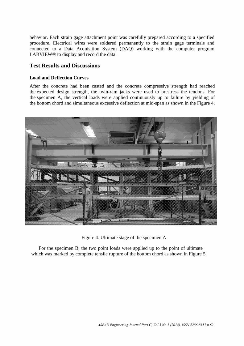
the bottom chord and simultaneous excessive deflection at mid-span as shown in the Figure 4.
Figure 4. Ultimate stage of the specimen A
For the specimen B, the two point loads were applied up to the point of ultimate
which was marked by complete tensile rupture of the bottom chord as shown in Figure 5.
ASEAN Engineering Journal Part C, Vol 3 No 1 (2014), ISSN 2286-8151 p.62

Figure 5. Ultimate stage of the specimen B
The steel trusses specimen C and D were basically identical to that of the specimen A and
B except that there was no concrete composite slab. The specimen C was loaded with the two
point loads increasing from zero up to the point of initiation of elastic buckling of the top
chord as shown in Figure 6.
Figure 6. Ultimate stage of the specimen C
ASEAN Engineering Journal Part C, Vol 3 No 1 (2014), ISSN 2286-8151 p.63

For specimen D, tendons were stressed up to 460MPa and the loads were applied up to
the ultimate in the same mode as for the specimen C causing bucking in the top chord of the
predicted load as shown in Figure 7.
Figure 7. Ultimate stage of the specimen D
Test results are compared with the theoretical analysis. The calculation of the load
and deflection relation of the post-tensioned composite truss starts when the ram loads
were applied at the third points.
The tendon force increases from initial jacking force (P) to (P+ΔP) where ∆P is the
increase in tendon force due to the additional straining from the ram loads. Since this is the
unbonded prestressing structure, the method of the strain compatibility only at a section is
insufficient to calculate the ∆P. The strain compatibility of the whole structure must be
considered. Starting with the elongation in the composite truss along the alignment of the
tendons due to the vertical applied ram loads, denoted as δ1p, is then calculated from
Equation (1)
dx
xAxE
xFxF
P
n
i
L
ii
ii
p
1 0
2,1,
2
1
1
(1)
Then the flexibility elongation coefficient, denoted as δ11, which is the elongation in the
composite truss along the alignment of the tendons generated by a unit load in the tendon, can
be calculated from Equation (2)
ASEAN Engineering Journal Part C, Vol 3 No 1 (2014), ISSN 2286-8151 p.64

dxxAxE
xFxFdx
xAxE
xFxF
P
m
j
L
jj
jjn
i
L
ii
ii
1 0
2,2,
1 0
2,2,
2
11
1
(2)
The compatibility condition of the final relative displacement of the tendon is
applied from Equation (3)
pP 111 (3)
From Equation (3), the increase in tendon force due to the applied ram loads ∆P can be
determined. After the internal forces in the composite truss are known, according to the
equilibrium condition with the applied loads, the vertical deflection, denoted as Δy, due to the
stresses in every parts is then can be calculated from Equation (4)
dx
xAxE
xFxF
P
n
i
L
ii
ii
y
1 0
3,1,
3
1
(4)
The above calculation procedure is applicable for both elastic stage and the non-linear
stage. For the non-linear analysis, the iteration procedure is required. After the increase in
tendon internal force due to the additional straining from the ram loads (∆P) is calculated from
Equations (1), (2) and (3), all the internal forces in the truss members can then be calculated.
Each of the truss members is checked. If the strain reaches the yield strain, the new value of
the modulus of elasticity will be replaced as the Etangent in the strain hardening zone from the
Table 3. The whole iterative process is then start again to find ∆P, internal forces and internal
strain until one of the truss member reaches the tensile strain at the ultimate stage. The related
∆P at the ultimate stage is then used to calculated the ultimate moment capacity from
Equations (5), (6), (7) and (8) explained in section 6.1
All of the symbols, notations and abbreviations are listed below;
Fi,1(x) is the internal forces in truss member, i, due to the vertical applied ram loads.
Fi,2(x) is the internal forces in truss member, i, due to the unit load along the tendon alignment.
Fi,3(x) is the internal forces in truss member, i, due to the unit load applied vertically at mid-
span.
δFi,2(x) is the virtual internal forces in truss member, i, due to the unit load along the tendon
alignment.
δFi,3(x) is the virtual internal forces in truss member, i, due to the unit load applied vertically
at mid-span.
Fj,2(x) is the internal forces in tendon, j, due to the unit load along the tendon alignment.
δFj,2(x) is the virtual internal forces in tendon, j, due to the unit load along the tendon
alignment.
Ei(x) is the modulus of elasticity of truss member, i, as the function of axial strain at the
iterative applied load.
Ej(x) is the modulus of elasticity of tendon, j, as the function of axial strain at the iterative
applied load.
Ai(x) is the cross sectional area of truss member, i.
Aj(x) is the cross sectional area of tendon, j.
δP2 is the unit load along the tendon alignment.
δP3 is the unit load applied vertically at mid-span.
n is the number of truss member.
ASEAN Engineering Journal Part C, Vol 3 No 1 (2014), ISSN 2286-8151 p.65

m is the number of tendon.
The predicted load and deflection relations show a good agreement with the experimental
results as shown in Figure 8. This is a favorable indication that the theoretical analysis
adopted is valid. It is believed that the differences between the calculated values and the
experimental data are primarily due to the slip of the anchorage wedges of the prestressing
tendon with a loud noise during the tests.
Figure 8. Load and deflection curves for specimen A and B
From Figure 8, the additional 7.9% of the cross sectional area of the post-
tensioned tendons compared to the tensile bottom chord area of the truss resulted in the
maximum total load of 684kN (Specimen A) which was 20.4% higher than the total load
of 568kN for the case without post-tensioning. (Specimen B)
ASEAN Engineering Journal Part C, Vol 3 No 1 (2014), ISSN 2286-8151 p.66
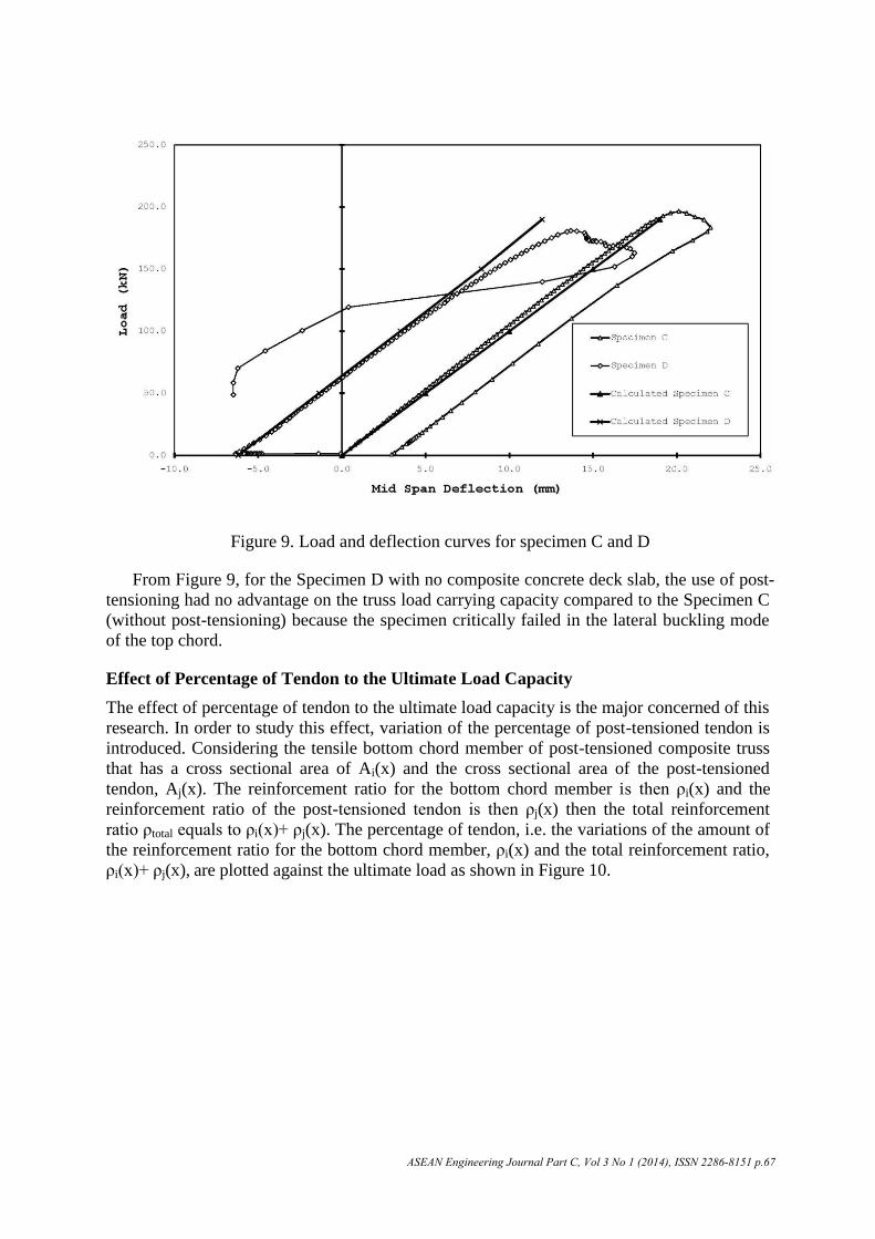
Figure 9. Load and deflection curves for specimen C and D
From Figure 9, for the Specimen D with no composite concrete deck slab, the use of post-
tensioning had no advantage on the truss load carrying capacity compared to the Specimen C
(without post-tensioning) because the specimen critically failed in the lateral buckling mode
of the top chord.
Effect of Percentage of Tendon to the Ultimate Load Capacity
The effect of percentage of tendon to the ultimate load capacity is the major concerned of this
research. In order to study this effect, variation of the percentage of post-tensioned tendon is
introduced. Considering the tensile bottom chord member of post-tensioned composite truss
that has a cross sectional area of Ai(x) and the cross sectional area of the post-tensioned
tendon, Aj(x). The reinforcement ratio for the bottom chord member is then ρi(x) and the
reinforcement ratio of the post-tensioned tendon is then ρj(x) then the total reinforcement
ratio ρtotal equals to ρi(x)+ ρj(x). The percentage of tendon, i.e. the variations of the amount of
the reinforcement ratio for the bottom chord member, ρi(x) and the total reinforcement ratio,
ρi(x)+ ρj(x), are plotted against the ultimate load as shown in Figure 10.
ASEAN Engineering Journal Part C, Vol 3 No 1 (2014), ISSN 2286-8151 p.67

Figure 10. Effect of percentage of tendon on ultimate load capacity
From Figure 10, the effect of the percentage of tendon for various modes of failure has
a significant effect on the ultimate load capacity of the structure. The additional percentage
of tendon means the additional higher-strength tensile cross sectional area which leads to
the advantage on the ultimate load capacity of the composite truss.
It improves the ultimate load capacity, but on the other hand, the higher percentage of the
tendon can cause buckling failure of the truss bottom chord during the prestressing. The
lateral bracing is an important concern when the percentage of the tendon reinforcement is
increased. Lower dotted horizontal line is the limited ultimate load if the lateral bracings were
provided at four locations; at each of the two supports and at two third points from both
support of the truss. If the number of the lateral bracings increases to five locations; by
adding the mid-span bracing, the ultimate load capacity increases to the middle dotted
horizontal line. If all of the truss members are braced continuously, the ultimate load capacity
will be limited by the yielding of the truss member in compression during the prestressing as
shown by the upper dotted horizontal line.
Effect of Percentage of Tendon to the Rotational Capacity
The effect of the prestressing tendon on the rotational capacity of a post-tensioned composite
truss is also studied in this research. In order to study this effect, the percentage of tendon are
plotted against the rotational capacity as shown in Figure 11.
ASEAN Engineering Journal Part C, Vol 3 No 1 (2014), ISSN 2286-8151 p.68

Figure 11. Effect of percentage of tendon on the rotational capacity
From Figure 11, the amount of the strengthening tendon affects the rotational capacity. It
reduces the ratio of the ultimate curvature (Øu) to the yield curvature (Øy). To maintain the
ductile failure mode, this relation can be utilized to achieve the required rotational capacity of
the post-tensioned composite truss for the design purpose. By given the top surface concrete
strain equals to the crushing strain and the tensile stress in the bottom chord and the tendons
equals to the ultimate strength, the actual neutral axis in which the summation of the concrete
compression equals to the total tension from the bottom chord and the tendon can be
determined. The curvature at the ultimate stage then can be calculated from the top surface
concrete strain divided by the distance from the top concrete surface to the neutral axis.
Effect of Percentage of Tendon to the Effective Moment of Inertia
Regarding the nature of the stiffness of the truss system compared to the beam-system, the
determination of the flexural stiffness of the composite truss from the transformed section
method, Itransf, always gives the higher stiffness value than the observed effective
experimental results. The effective flexural stiffness, Ieff, for the truss system is
approximately 60%-80% of the Itransf.; Samuelson (2002) and Brattland et al (1986) However,
from the experimental results as well as the theoretical analysis, the percentage of tendon
affects the effective flexural stiffness of the composite truss as shown in Figure 12. It
improves the linearity of the load and deflection relations.
ASEAN Engineering Journal Part C, Vol 3 No 1 (2014), ISSN 2286-8151 p.69

Figure 12. Effect of percentage of tendon to the effective moment of inertia
From Figure 12, the calculated results of the Ieff to Itransf ratio from the slope of the
load and deflection curves are very close to the experimental results. The higher
percentage of tendon improves the ratio of the effective flexural stiffness and the
transformed section flexural stiffness, (Ieff / Itransf), which means that the transformed
section method will give more accuracy to the approximation of the composite truss
defection calculation.
Summarize the Advantages of Strengthening the Composite Truss by Post-
Tensioning
From the experimental results as well as the theoretical analysis, the advantages of
strengthening the composite truss by post-tensioning are presented for the general case of the
post-tensioned composite truss.
Ultimate Moment Capacity
The ultimate moment capacity of a composite truss strengthened by post-tensioning can be
computed from Equations (5), (6), (7) and (8);
2max
ahTM u (5)
bf
Ta
c '85.0
max (6)
ccuui btfQPPfxAT '85.0,,)(minmax (7)
ASEAN Engineering Journal Part C, Vol 3 No 1 (2014), ISSN 2286-8151 p.70

dxxAxE
xFxFdx
xAxE
xFxF
P
dxxAxE
xFxF
PP
m
j
L
jj
jjn
i
L
ii
ii
n
i
L
ii
ii
1 0
2,2,
1 0
2,2,
2
1 0
2,1,
2
max
1
1
(8)
All of the additional symbols, notations and abbreviations are listed below;
Mu is the ultimate moment capacity of the post-tensioned composite truss.
Tmax is the maximum tensile force in the bottom chord.
h is the distance between the top concrete surface to the centroid of the bottom chord
member. fc’ is the concrete compressive strength of the deck slab.
fu is the tensile strength of the truss bottom chord member.
b is the effective width of the composite truss.
ΣQu is the summation of the horizontal shear stud capacity between the points of maximum to
the zero moment.
tc is the concrete deck slab thickness.
∆Pmax is the increase in tendon force at the ultimate stage.
Please be noted that ΔP in Equation (8) is the increase in tendon force at the time the
tensile stress of the truss bottom chord member reaches the tensile strength of its material.
Ultimate Shear Capacity
The ultimate shear capacity of the post-tensioned composite truss depends on the tensile
strength of the critical web members in tension and the buckling strength of the critical web
members in compression. The following Equation (9) can be applied;
cruPPLLDLweb , (9)
All of the additional symbols, notations and abbreviations are listed below;
σweb is the web member stress in tension/compression.
σDL is the web member stress due to the dead load.
σLL is the web member stress due to the live load
σP is the web member stress due to the post-tensioning.
σΔP is the web member stress due to the increasing of the post-tensioning from the live load.
σu is the ultimate tensile strength of the web member material.
σcr is the critical buckling strength of the web member.
Maximum Applicable Tendon
From the study and the experimental preparation, the maximum applicable tendon is also
mentioned. The tendon prestressing force causes a compressive stress in the bottom chord of
the composite truss. If the lateral bracings are provided adequately, the bottom chord stress
may reach the compressive strength. The maximum prestressing force for this criterion can be
calculated from Equation (10)
ASEAN Engineering Journal Part C, Vol 3 No 1 (2014), ISSN 2286-8151 p.71

⋅+
≤
transf
b
transf
u
Iye
A
P1
σ (10)
All of the additional symbols, notations and abbreviations are listed below; σu is the ultimate compressive strength of the truss bottom chord member material. Atransf is the transformed sectional area of the composite truss. Itransf is the transformed moment of inertia of the composite truss. e is the eccentricity from the distance from the composite truss neutral axis to the centroid of bottom chord. yb is the distance from the composite truss neutral axis to the bottom fiber of the steel bottom chord member.
If there is no lateral support available, the truss web members can be considered as the lateral support as refer to Benson (2009) since the truss web members welded to the top chord member which behaves like a fixed base by the anchored shear stud connectors embedded in the concrete slab. The lateral translation stiffness of the bottom chord considering the web member as the lateral bracings, KH, is computed from Equation (11)
33
w
wwH d
IEK ⋅⋅= (11)
Figure 13: Loaded configuration of bottom chord under post-tensioning with web member as lateral bracing
ASEAN Engineering Journal Part C, Vol 3 No 1 (2014), ISSN 2286-8151 p.72

Refer to the Figure 13, take the equilibrium condition;
uH LKP 2 (12)
Rearrange the equation; the maximum post-tensioned force that can be applied to the bottom
chord without any buckling problem can be compute from Equation (13)
2
33
u
w
ww L
d
IEP (13)
All of the additional symbols, notations and abbreviations are listed below;
Ew is the modulus of elasticity of the web member in the lateral direction.
Iw is the sectional moment of inertia of the web member in the lateral direction.
dw is the total distance from the concrete bottom surface to the centroid of bottom chord.
Lu is the unbraced length between the two adjacent web members.
Since during prestressing, the top surface of the concrete slab is under tensile stress. The
next limitation of the maximum prestressing force to prevent the concrete top surface from
cracking during the prestressing is computed from Equation (14)
transf
t
transf
r
I
ye
A
nfP
1(14)
All of the additional symbols, notations and abbreviations are listed below;
fr is the concrete modulus of rupture of the deck slab.
n is the modular ratio computed from the ratio of the steel elastic modulus over the concrete
elastic modulus.
yt is the distance from the composite truss neutral axis to the top fiber of the concrete deck
slab.
The final limitation for the maximum tendon force is the tendon strength itself. The total
internal stress from the initial jacking stress and the increasing stress from the applied ram
loads must remain less than or equal to the ultimate strength of the tendon material as defined
by Equation (15)
)(xAfPP jpu (15)
All of the additional symbols, notations and abbreviations are listed below;
fpu is the ultimate tensile strength of the tendon material.
Aj(x) is the cross sectional area of the tendon.
The maximum post-tensioned force must satisfy Equations (9), (10), (13), (14) and (15).
Conclusions
Base on the experimental results and also the theoretical analysis, composite
trusses strengthened by the external high strength tendons are believed to perform
better than conventional composite trusses. With respect to this noticeably better
performance, the following observations are presented:
ASEAN Engineering Journal Part C, Vol 3 No 1 (2014), ISSN 2286-8151 p.73

The additional 7.9% of the cross sectional area of the post-tensioned tendons compared to the tensile bottom chord area of the truss resulted in the 20.4% of the load carrying capacity higher than the case without post-tensioning.
Beneficial aspects of post-tensioning are most notable for the steel trusses with concrete composite deck slab. The concrete decks provide the effective lateral support for the steel top chord under the ultimate stage and also perform rigid base for the truss web member as the lateral support for the bottom chord to prevent the lateral buckling failure under the post-tensioning stage.
Failure mode of the post-tensioned composite truss occurs by yielding of the bottom chord while the tendon is still in the elastic range. This behavior is quite desirable as it results in a ductile failure mode with the better rotational capacity which displays detectable warning deformation indicative of impending collapse.
Local buckling of truss member should be prevented when the prestressing level is increased. Sufficient lateral bracings for the truss members are required to apply the post-tensioning.
Percentage of tendon improves the linearity of the load and deflection response. By applying the prestressing forces, the stiffness calculated from the transformed section method can be applied with the better accuracy for the approximate deflection prediction.
Shear stud connectors must provide sufficient shear transfer strength especially for post-tensioned composite truss since the interface shear force is higher than in the case of ordinary composite truss.
Summarize of the advantages of strengthening the composite truss by external post-
tensioning in both the flexural strength and the shear capacity considering the amount of the post-tensioned tendons are presented as well as the limitations of the maximum tendon applicable; the compression failure of the bottom chord due to the post-
tensioning, the buckling of the truss members due to the post-tensioning, the cracking of the top surface concrete slab and the tendon tensile strength itself.
Acknowledgement
The author would like to thank TRF (Thailand Research Fund) through the Royal
Golden Jubilee Ph.D. Program (Grant No PHD/0257/2545) awarded to Mr. Kanokpat
Chanvaivit and Prof. Dr. Ekasit Limsuwan for the Ph.D. Study in Chulalongkorn
University, Thailand. The experimental study was conducted in the structural laboratory
of the Department of Civil Engineering, University of New Brunswick, Fredericton,
Canada with funding from NSERC which is greatly appreciated along with in kind
contributions from DSI America, LaFarge and PCA.
References
[1] ACI Committee 318, Building Code Requirements for Structural Concrete (ACI 31811) and Commentary (ACI 318R-11), American Concrete Institute, Michigan, United States, 2011.
[2] J.H. Ahn, C.Y Jung, and S.H. Kim, “Evaluation on structural behaviors of pre-stressed composite beams using external prestressing member,” Structural Engineering and Mechanics: An International Journal , Vol. 34, No. 2, 2010.
[3] American Institute of Steel Construction, Metric Load and Resistance Factor Design Specification for Structural Steel Buildings, American Institute of Steel Construction Inc, Chicago, Illinois, United States, 2010.
ASEAN Engineering Journal Part C, Vol 3 No 1 (2014), ISSN 2286-8151 p.74

[4] ASCE – ACI Joint Committee on Composite Construction, “Tentative recommendations for the design and construction of composite beams and girders for buildings,” Journal of the Structural Division ASCE, Vol. 86, No. 12, pp. 73-92, 1960.
[5] ASCE (American Society of Civil Engineers) Task Committee on Design Criteria for Composite Structures in Steel and Concrete, “Proposed specification and commentary for composite joists and composite trusses,” Journal of Structural Engineering ASCE, Vol. 122, No. 4, pp. 350-358, 1996.
[6] B.M. Ayyub, A. Ibrahim, and D. Schelling, “Posttensioned trusses: Analysis and design,” Journal of Structural Engineering ASCE, Vol. 116, No. 6, pp. 1491-1505, 1990.
[7] B.M. Ayyub, and A. Ibrahim, “Posttensioned trusses: Reliability and redundancy,” Journal of Structural Engineering ASCE, Vol. 116, No. 6, pp. 1507-1521, 1990.
[8] B.M. Ayyub, Y.G. Sohn, and H. Saadatmanesh, “Prestressed composite girders under positive moment,” Journal of Structural Engineering ASCE, Vol. 116, No. 11, pp.2931-2951, 1990.
[9] A. Brattland, and D.J.L. Kennedy, Shrinkage and Flexural Tests of Two Full-Scale Composite Trusses, Thesis (Master’s), Department of Civil Engineering, University of Alberta, Canada, 1986.
[10] S. Benson, Stability of Open Web Steel Joists Subjected to Wind Uplift, Thesis (PhD), Department of Civil Engineering, University of New Brunswick, Canada, 2009.
[11] Canadian Institute of Steel Construction, Handbook of Steel Construction, Quadratone
Graphics Ltd., Toronto, Ontario, Canada, 2011.
[12] S. Chen, Y. Jia, and X. Wang, “Experimental study of moment redistribution and load carrying capacity of externally prestressed continuous composite beams,” Structural Engineering and Mechanics, An International Journal, Vol. 31, No. 5, pp. 605-619, 2009.
[13] K.B. Han, and S.K. Park, “Parametric study of truss bridges by the post-tensioning method,” Canadian Journal of Civil Engineering, Vol. 32, pp. 420-429, 2005.
[14] P.G. Hoadley, “Behavior of prestressed composite steel beams,” Journal of the Structural Division ASCE, Vol. 89, No. 3, pp. 21-33, 1963.
[15] S.H. Kim, C.Y. Jung, and J.H. Ahn, “Ultimate strength of composite structure with different degrees of shear connection,” Steel and Composite Structures: An International Journal, Vol. 11, No. 5, pp. 375-390, 2011.
[16] R.E. Klingner, and J.A. Mendonca, “Shear capacity of short anchor bolts and welded studs: A litterature review,” American Concrete Institute (ACI) Journal, Vol. 79, No. 5, pp. 339-349, 1982.
[17] D. Lam, and E. El-Lobody, “Behavior of headed stud shear connectors in composite beam,” Journal of Structural Engineering ASCE, Vol. 131, No. 1, pp. 96-107, 2005.
[18] T. Lou, and Y. Xiang, “Numerical analysis of second-order effects of externally prestressed concrete beams,” Structural Engineering and Mechanics: An International Journal, Vol. 35, No. 5, 2010.
[19] J. Nie, Y. Xiao, Y. Tan, and H. Wang, “Experimental studies on behavior of composite steel high-strength concrete beams,” American Concrete Institute (ACI) Structural Journal, Vol. 101, No. 2, pp. 245-251, 2004.
[20] M. Ohsaki, and J. Zhang, “Stability conditions of prestressed pin-jointed structures,” International Journal of Non-Linear Mechanics Elsevier, Vol. 41, pp. 1109-1117, 2006.
[21] H. Saadatmanesh, P. Albrecht, and B.M. Ayyub, “Analytical study of prestressed composite beams,” Journal of Structural Engineering ASCE, Vol. 115, No. 9, pp.2364-2381, 1989.
[22] H. Saadatmanesh, P. Albrecht, and B.M. Ayyub, “Experimental study of prestressed composite beams,” Journal of Structural Engineering ASCE, Vol. 115, No. 9, pp.2348-2363, 1989.
[23] H. Saadatmanesh, P. Albrecht, and B.M. Ayyub, “Guidelines for flexural design
ASEAN Engineering Journal Part C, Vol 3 No 1 (2014), ISSN 2286-8151 p.75

[25] B. Uy, and S. Craine, “Static flexural behavior of externally post-tensioned steel-concrete composite beams,” Advances in Structural Engineering, Vol. 7, No. 1, pp. 1-20, 2004.
[26] F.J. Vechio, P. Gauvreau, and K. Liu, “Modeling of unbonded post-tensioned concrete beams critical in shear,” ACI Structural Journal, Vol. 103, No. 1, pp. 57-64, 2006.
ASEAN Engineering Journal Part C, Vol 3 No 1 (2014), ISSN 2286-8151 p.76
of prestressed composite beams,” Journal of Structural Engineering ASCE, Vol. 115, No. 11, pp. 2944-2961, 1989.[24] D. Samuelson, “Composite steel joist,” Engineering Journal, pp. 111-120, 2002.