Embed Size (px)
Citation preview
資料-00
StrainerStrainer
139
P139-140_扉_ストレーナー 2011.3.10 1:30 PM ページ 1
資料-00
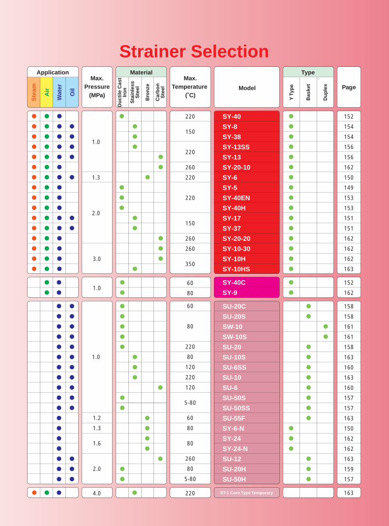
Strainer Selection
●
●
●
●
●�
●
●
●
●
●
●
●
●
●
●
●
●
●
●
●
●
●
●
●
●
●
●
●
●
●
●
●�
●
●
●
●
●�
●
●
●
●
●
●
●
●
●
●
●
�
●
●�
●
●
�
●
�
�
�
●
●�
●
●
●
●
●
●
●
●
●
●
●
●
●
●
●
●�
1.0
1.3
2.0
3.0
220
150
220
260
220
220
150
260
260
350
1.060
80
152
154
154
156
156
162
150
149
153
153
151
151
162
162
162
163
●
●�
152
162
�
�
�
�
�
�
�
�
�
�
�
�
●
●�
●
●
●�
�
�
●
●�
●
●�
●
●�
●
●�
�
�
�
●�
●
●�
�
�
●
●
158
158
161
161
158
163
160
163
160
157
157
163
150
162
162
163
159
157
SY-40
SY-8
SY-38
SY-13SS
SY-13
SY-20-10
SY-6
SY-5
SY-40EN
SY-40H
SY-17
SY-37
SY-20-20
SY-10-30
SY-10H
SY-10HS
SY-40C
SY-9
1.0
1.2
1.3
1.6
2.0
60
80
220
80
120
220
120
5-80
60
80
80
260
80
5-80
SU-20C
SU-20S
SW-10
SW-10S
SU-20
SU-10S
SU-6SS
SU-10
SU-6
SU-50S
SU-50SS
SU-55F
SY-6-N
SY-24
SY-24-N
SU-12
SU-20H
SU-50H
●
●�
●
●�
�
●
●�
●
●
●�
●
●
●�
●
●
●�
●
●
●�
●
●
●�
●�
●
●�
●
●
●�
●
●
●�
●
●
●�
�
●
●�
●�
�
Type
Y T
ype
Bas
ket
Du
ple
x
Max.Pressure
(MPa)
Max.Temperature
(˚C)Model Page
�
●
●
●
●
●�
●�
●
�
�
�
�
�
�
●�
●
●
�
�
�
�
●
●
�
�
�
�
�
�
●
●
●
�
�
�
�
�
�
●
●
●�
●
●�
●
●�
●�
�
�
�
�
●
●�
�
�
�
�
�
●�
●�
�
�
�
�
�
●�
●
●�
�
�
�
�
�
�
�
�
�
�
�
�
�
�
�
�
�
�
�
�
�
●�
●�
●
●
�
�
�
�
�
�
�
�
●
�
�
�
�
�
�
●
Material
Du
ctile
Cas
tIr
on
Sta
inle
ssS
teel
Bro
nze
Car
bo
nS
teel
Application
Ste
am
Air
Wat
er
Oil
4.0 220 � 163ST-1 Corn Type Temporary●�● ●�� ●�
140
P139-140_扉_ストレーナー 2011.3.10 1:30 PM ページ 2
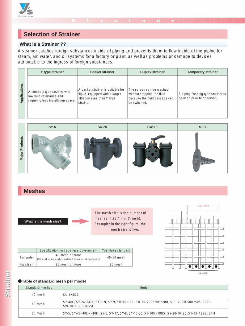
The screen can be washedwithout stopping the fluidbecause the fluid passage canbe switched.
Y type strainer Basket strainer Duplex strainer Temporary strainer
S t r a i n e r
Str
ain
erS
trai
ner
7-3, Futano-cho, Mizuho-ku, Nagoya, 467-0861, Japan Phone: 81-52-881-7199 Fax: 81-52-881-7201
www.yoshitake.jp141
スト-23
What is a Strainer ??
Maj
or
Pro
du
cts
What is the mesh size?
Selection of Strainer
Meshes
A strainer catches foreign substances inside of piping and prevents them to flow inside of the piping forsteam, air, water, and oil systems for a factory or plant, as well as problems or damage to devicesattributable to the ingress of foreign substances.
Ap
plic
atio
ns
A compact type strainer withlow fluid resistance andrequiring less installation space.
The mesh size is the number of
meshes in 25.4 mm (1 inch).
Example: In the right figure, the
mesh size is five.
A basket strainer is suitable forliquid, equipped with a largerfiltration area than Y typestrainer.
A piping flushing type strainer tobe used prior to operation.
●Table of standard mesh per model
Specification for Japanese government40 mesh or more
(80 mesh or more when installed before a solenoid valve)
80 mesh or more
Yoshitake standard
40・60 mesh
80 mesh
For water
For steam
25.4 mm
●�●�●�●�●�
5 mesh
SU-6・6SS
SY-5, SY-40・40EN・40H, SY-6, SY-17, SY-8, SY-10-30, SY-10H・10HS, SY-20-10・20, SY-13・13SS, ST-1
40 mesh
60 mesh
80 mesh
Standard meshes Model
SY-40C, SY-24・24-N, SY-6-N, SY-9, SU-10・10S, SU-20・20S・20C・20H, SU-12, SU-50H・50S・50SS, SW-10・10S, SU-55F
SY-5 SU-20 SW-10 ST-1
P141-142_スト 2011.3.10 1:31 PM ページ 1
S t r a i n e r
Str
ain
erS
trai
ner
7-3, Futano-cho, Mizuho-ku, Nagoya, 467-0861, Japan Phone: 81-52-881-7199 Fax: 81-52-881-7201www.yoshitake.jp
142
スト-24
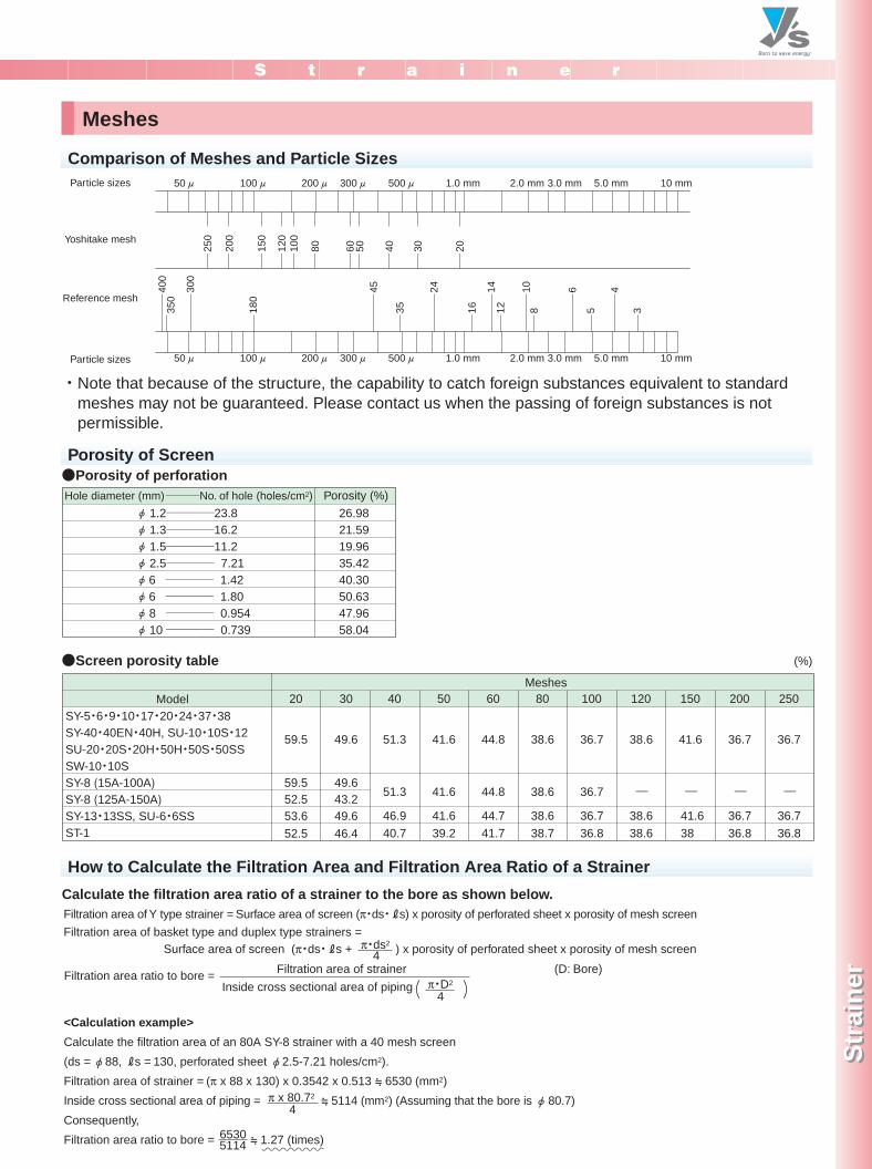
Comparison of Meshes and Particle Sizes
Porosity of Screen
Meshes
・Note that because of the structure, the capability to catch foreign substances equivalent to standardmeshes may not be guaranteed. Please contact us when the passing of foreign substances is notpermissible.
●Screen porosity table
●Porosity of perforationPorosity (%)
26.9821.5919.9635.4240.3050.6347.9658.04
1.2────23.8φ φ�φ�φ�φ�φ�φ�φ�
1.3────16.21.5────11.22.5──── 7.216 ──── 1.426 ──── 1.808 ──── 0.95410──── 0.739
Hole diameter (mm) ───No. of hole (holes/cm2)
50μ� 100μ� 200μ�300μ� 500μ� 1.0 mm 2.0 mm 3.0 mm 5.0 mm 10 mm
50μ� 100μ� 200μ�300μ� 500μ� 1.0 mm 2.0 mm 3.0 mm 5.0 mm 10 mm
250
200
150
120
100
80 60 50 40 30 20
400
300
45 24 14 10 6 4
350
180
35 16 12 8 5 3
Particle sizes
Yoshitake mesh
Reference mesh
Particle sizes
Meshes20 30 40 50 60 80 100 120 150 200 250
59.5 49.6 51.3 41.6 44.8 38.6 36.7 38.6 41.6 36.7 36.7
59.5 49.652.5 43.2 51.3 41.6 44.8 38.6 36.7 ―� ―� ―� ―�
53.6 49.6 46.9 41.6 44.7 38.6 36.7 38.6 41.6 36.7 36.752.5 46.4 40.7 39.2 41.7 38.7 36.8 38.6 38 36.8 36.8
ModelSY-5・6・9・10・17・20・24・37・38SY-40・40EN・40H, SU-10・10S・12�SU-20・20S・20H・50H・50S・50SSSW-10・10SSY-8 (15A-100A)�SY-8 (125A-150A)SY-13・13SS, SU-6・6SSST-1
How to Calculate the Filtration Area and Filtration Area Ratio of a Strainer
<Calculation example>
Calculate the filtration area of an 80A SY-8 strainer with a 40 mesh screen (ds = φ 88,Rs = 130, perforated sheet φ 2.5-7.21 holes/cm2).Filtration area of strainer = (π x 88 x 130) x 0.3542 x 0.513 = 6530 (mm2)Inside cross sectional area of piping = = 5114 (mm2) (Assuming that the bore is φ80.7)Consequently,Filtration area ratio to bore = = 1.27 (times)
Filtration area of basket type and duplex type strainers = Surface area of screen (π・ds・Rs + ) x porosity of perforated sheet x porosity of mesh screenπ・ds2
4
π x 80.72
4
65305114
π・D2
4 )�(�Filtration area ratio to bore = Filtration area of strainer
Inside cross sectional area of piping(D: Bore)
Calculate the filtration area ratio of a strainer to the bore as shown below.Filtration area of Y type strainer = Surface area of screen (π・ds・Rs) x porosity of perforated sheet x porosity of mesh screen
(%)
P141-142_スト 2011.3.10 1:31 PM ページ 2
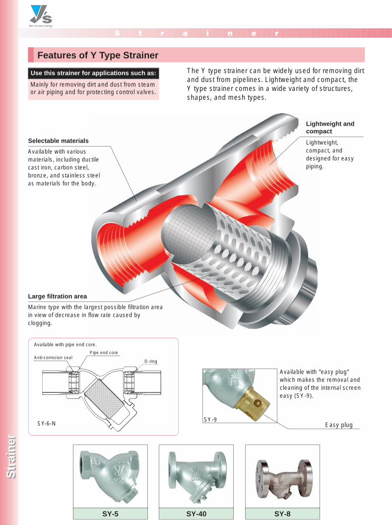
Lightweight andcompact
Lightweight,compact, anddesigned for easypiping.
S t r a i n e r
Str
ain
erS
trai
ner
7-3, Futano-cho, Mizuho-ku, Nagoya, 467-0861, Japan Phone: 81-52-881-7199 Fax: 81-52-881-7201
www.yoshitake.jp143
スト-25
Features of Y Type Strainer
The Y type strainer can be widely used for removing dirtand dust from pipelines. Lightweight and compact, theY type strainer comes in a wide variety of structures,shapes, and mesh types.
Use this strainer for applications such as:
Mainly for removing dirt and dust from steamor air piping and for protecting control valves.
Selectable materials
Available with variousmaterials, including ductilecast iron, carbon steel,bronze, and stainless steelas materials for the body.
Anti-corrosion sealPipe end core
O-ring
Available with pipe end core.
SY-6-N
SY-5 SY-40 SY-8
Available with "easy plug"which makes the removal andcleaning of the internal screeneasy (SY-9).
Easy plug
Large filtration area
Marine type with the largest possible filtration areain view of decrease in flow rate caused byclogging.
SY-9
P143-144_スト 2011.3.10 1:32 PM ページ 1
S t r a i n e r
Str
ain
erS
trai
ner
7-3, Futano-cho, Mizuho-ku, Nagoya, 467-0861, Japan Phone: 81-52-881-7199 Fax: 81-52-881-7201
www.yoshitake.jp144
スト-26
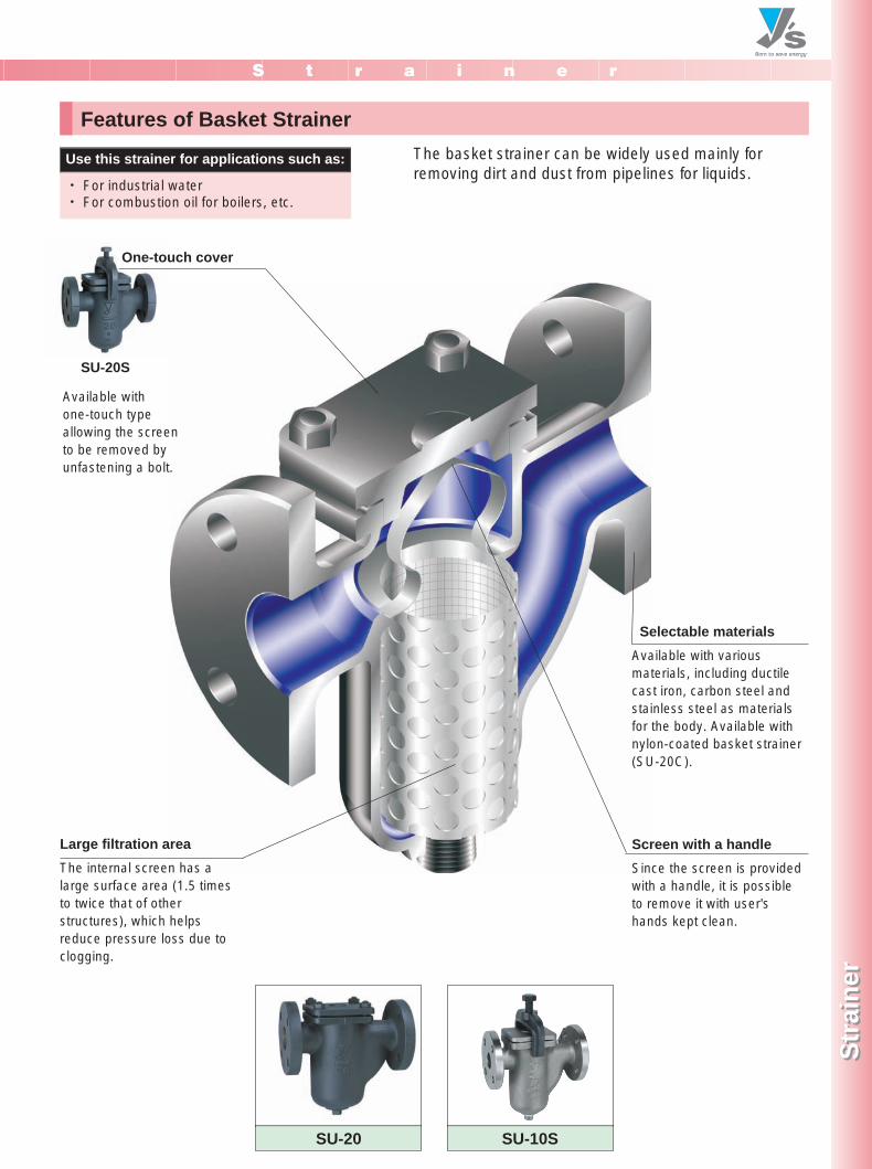
Features of Basket Strainer
The basket strainer can be widely used mainly forremoving dirt and dust from pipelines for liquids.
Use this strainer for applications such as:
・ For industrial water・ For combustion oil for boilers, etc.
Available with one-touch typeallowing the screento be removed byunfastening a bolt.
SU-20 SU-10S
Selectable materials
Available with variousmaterials, including ductilecast iron, carbon steel andstainless steel as materialsfor the body. Available withnylon-coated basket strainer(SU-20C).
Screen with a handle
Since the screen is providedwith a handle, it is possibleto remove it with user'shands kept clean.
Large filtration area
The internal screen has alarge surface area (1.5 timesto twice that of otherstructures), which helpsreduce pressure loss due toclogging.
One-touch cover
SU-20S
P143-144_スト 2011.3.10 1:32 PM ページ 2
S t r a i n e r
Str
ain
erS
trai
ner
7-3, Futano-cho, Mizuho-ku, Nagoya, 467-0861, Japan Phone: 81-52-881-7199 Fax: 81-52-881-7201
www.yoshitake.jp145
スト-27
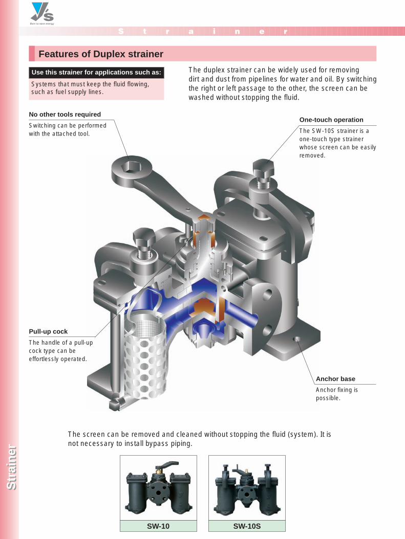
Features of Duplex strainer
The duplex strainer can be widely used for removingdirt and dust from pipelines for water and oil. By switchingthe right or left passage to the other, the screen can bewashed without stopping the fluid.
The screen can be removed and cleaned without stopping the fluid (system). It isnot necessary to install bypass piping.
Use this strainer for applications such as:
Systems that must keep the fluid flowing,such as fuel supply lines.
SW-10 SW-10S
One-touch operation
The SW-10S strainer is aone-touch type strainerwhose screen can be easilyremoved.
Anchor fixing ispossible.
No other tools required
Switching can be performedwith the attached tool.
Pull-up cock
The handle of a pull-upcock type can beeffortlessly operated.
Anchor base
P145-146_スト 2011.3.10 1:32 PM ページ 1
S t r a i n e r
Str
ain
erS
trai
ner
7-3, Futano-cho, Mizuho-ku, Nagoya, 467-0861, Japan Phone: 81-52-881-7199 Fax: 81-52-881-7201www.yoshitake.jp
146
スト-28
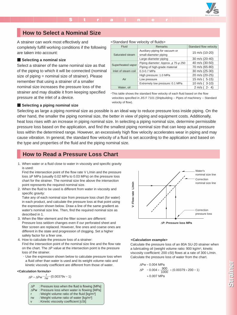
How to Select a Nominal Size
How to Read a Pressure Loss Chart
A strainer can work most effectively andcompletely fulfill working conditions if the followingare taken into account:
・This table shows the standard flow velocity of each fluid based on the flowvelocities specified in JIS F 7101 (Shipbuilding -- Pipes of machinery -- Standardvelocity of flow).
Select a strainer of the same nominal size as thatof the piping to which it will be connected (nominalsize of piping = nominal size of strainer). Pleaseremember that using a strainer of a smallernominal size increases the pressure loss of thestrainer and may disable it from keeping specifiedpressure at the inlet of a device.
When water or a fluid close to water in viscosity and specific gravityis used:Find the intersection point of the flow rate V L/min and the pressureloss ∆P MPa (usually 0.02 MPa to 0.03 MPa) on the pressure losschart for the strainer. The nominal size line above the intersectionpoint represents the required nominal size.When the fluid to be used is different from water in viscosity andspecific gravity:Take any of each nominal size from pressure loss chart (for water)in each product, and calculate the pressure loss at that point usingthe expression shown below. Draw a line of the same gradient aswater's nominal size line. Then, find the required nominal size asdescribed in 1.When the filter element and the filter screen are different:Pressure loss seldom changes even if our perforated sheet andfilter screen are replaced. However, fine ones and coarse ones aredifferent in the state and progression of clogging. Set a highersafety factor for a finer one.How to calculate the pressure loss of a strainer:Find the intersection point of the nominal size line and the flow rateon the chart. The ∆P value at the intersection point is the pressureloss of the strainer.・Use the expression shown below to calculate pressure loss when
a fluid other than water is used and its weight volume ratio andkinetic viscosity coefficient are different from those of water.
1.
2.
3.
4.
Fluid
Saturated steam
Superheated vapor
Inlet of steam coil
Air
Water, oil
Auxiliary piping for vacuum orsmall-diameter pipingLarge-diameter pipingPiping diameter: Approx. φ 75-φ 250Piping of high-grade material0.3-0.7 MPaHigh pressure: 1.0 MPaLow pressureExtremely low pressure: 0.1 MPa
Remarks
15 m/s (10-20)
30 m/s (20-40)40 m/s (30-50)70 m/s (65-80)30 m/s (25-30)20 m/s (20-25)15 m/s ( 5-15)10 m/s ( 3-10) 2 m/s ( 2- 4)
Standard flow velocity
V: F
low
rate
L/m
in
∆P: Pressure loss MPa
Water's nominal size line
Correctionnominal size line
Correctionpressure loss
<Calculation formula>(0.00379v + 1)∆P = ∆Pw
∆P : Pressure loss when the fluid is flowing [MPa]∆Pw�: Pressure loss when water is flowing [MPa]r : Weight volume ratio of the fluid [kg/m3]rw : Weight volume ratio of water [kg/m3]v : Kinetic viscosity coefficient [cSt]
rrw
■ Selecting a nominal size
Selecting as large a piping nominal size as possible is an ideal way to reduce pressure loss inside piping. On theother hand, the smaller the piping nominal size, the better in view of piping and equipment costs. Additionally,heat loss rises with an increase in piping nominal size. In selecting a piping nominal size, determine permissiblepressure loss based on the application, and find the smallest piping nominal size that can keep actual pressureloss within the determined range. However, an excessively high flow velocity accelerates wear in piping and maycause vibration. In general, the standard flow velocity of a fluid is set according to the application and based onthe type and properties of the fluid and the piping nominal size.
■ Selecting a piping nominal size
<Calculation example>
∆Pw = 0.004 MPa∆P
= 0.007 MPa
x (0.00379 x 200 + 1)9001000
Calculate the pressure loss of an 80A SU-20 strainer when a lubricating oil (weight volume ratio: 900 kg/m3, kinetic viscosity coefficient: 200 cSt) flows at a rate of 300 L/min.Calculate the pressure loss of water from the chart.
= 0.004 x
<Standard flow velocity of fluids>
P145-146_スト 2011.3.10 1:32 PM ページ 2
S t r a i n e r
Str
ain
erS
trai
ner
7-3, Futano-cho, Mizuho-ku, Nagoya, 467-0861, Japan Phone: 81-52-881-7199 Fax: 81-52-881-7201
www.yoshitake.jp147
スト-29
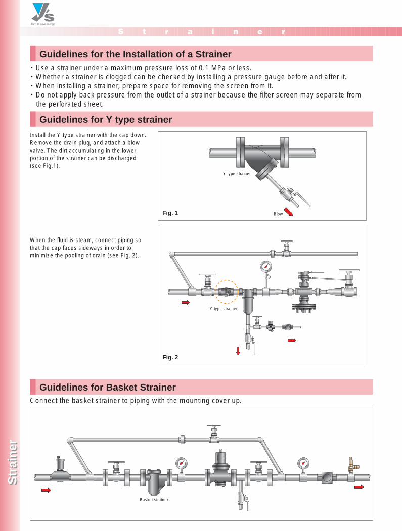
Guidelines for Y type strainer
Guidelines for the Installation of a Strainer
Guidelines for Basket Strainer
・ Use a strainer under a maximum pressure loss of 0.1 MPa or less.・Whether a strainer is clogged can be checked by installing a pressure gauge before and after it.・When installing a strainer, prepare space for removing the screen from it.・ Do not apply back pressure from the outlet of a strainer because the filter screen may separate from
the perforated sheet.
Install the Y type strainer with the cap down.Remove the drain plug, and attach a blowvalve. The dirt accumulating in the lowerportion of the strainer can be discharged (see Fig.1).
When the fluid is steam, connect piping sothat the cap faces sideways in order tominimize the pooling of drain (see Fig. 2).
Connect the basket strainer to piping with the mounting cover up.
Basket strainer
Fig. 1 Blow
Y type strainer
Fig. 2
Y type strainer
P147-148_スト 2011.3.10 1:47 PM ページ 1
S t r a i n e r
Str
ain
erS
trai
ner
7-3, Futano-cho, Mizuho-ku, Nagoya, 467-0861, Japan Phone: 81-52-881-7199 Fax: 81-52-881-7201
www.yoshitake.jp148
スト-30
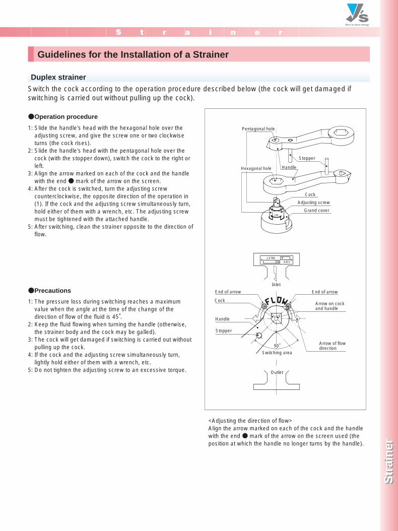
Guidelines for the Installation of a Strainer
1: Slide the handle's head with the hexagonal hole over theadjusting screw, and give the screw one or two clockwiseturns (the cock rises).
2: Slide the handle's head with the pentagonal hole over thecock (with the stopper down), switch the cock to the right orleft.
3: Align the arrow marked on each of the cock and the handlewith the end ● mark of the arrow on the screen.
4: After the cock is switched, turn the adjusting screwcounterclockwise, the opposite direction of the operation in(1). If the cock and the adjusting screw simultaneously turn,hold either of them with a wrench, etc. The adjusting screwmust be tightened with the attached handle.
5: After switching, clean the strainer opposite to the direction offlow.
1: The pressure loss during switching reaches a maximumvalue when the angle at the time of the change of thedirection of flow of the fluid is 45°.
2: Keep the fluid flowing when turning the handle (otherwise,the strainer body and the cock may be galled).
3: The cock will get damaged if switching is carried out withoutpulling up the cock.
4: If the cock and the adjusting screw simultaneously turn,lightly hold either of them with a wrench, etc.
5: Do not tighten the adjusting screw to an excessive torque.
<Adjusting the direction of flow>Align the arrow marked on each of the cock and the handlewith the end ● mark of the arrow on the screen used (theposition at which the handle no longer turns by the handle).
Switch the cock according to the operation procedure described below (the cock will get damaged ifswitching is carried out without pulling up the cock).
Pentagonal hole
Stopper
Handle
Cock
Adjusting screw
Grand cover
Stopper
Handle
Cock
Inlet
90°�
End of arrow End of arrow
Arrow on cock and handle
Arrow of flow direction
SIZEINLET
NO.A
cw
Outlet
Switching area
Hexagonal hole
Duplex strainer
●Operation procedure
●Precautions
P147-148_スト 2011.3.10 1:47 PM ページ 2
Y-type Ductile iron
S t r a i n e r
Str
ain
erS
trai
ner
7-3, Futano-cho, Mizuho-ku, Nagoya, 467-0861, Japan Phone: 81-52-881-7199 Fax: 81-52-881-7201www.yoshitake.jp
149
スト-01
SteamSteam A i r
A i rWaterWater
SteamSteam A i r
A i rWaterWater
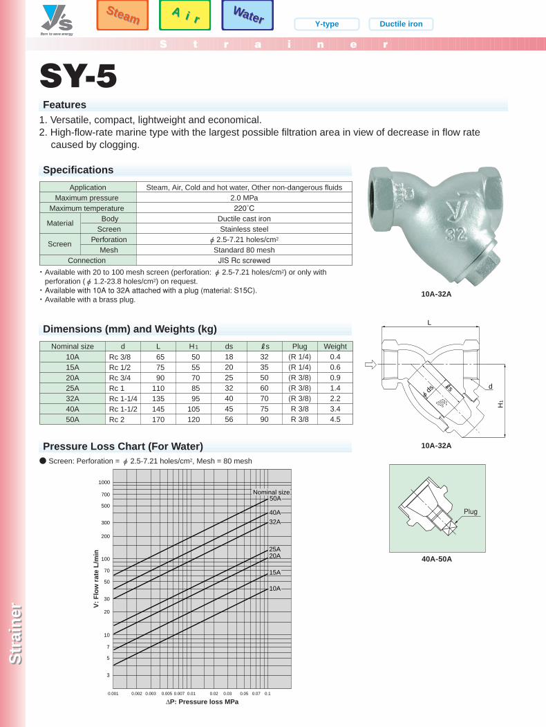
SY-5Features
1. Versatile, compact, lightweight and economical.2. High-flow-rate marine type with the largest possible filtration area in view of decrease in flow rate
caused by clogging.
10A-32A
Specifications
ApplicationMaximum pressure
Maximum temperature Body Screen
PerforationMesh
Connection
Steam, Air, Cold and hot water, Other non-dangerous fluids2.0 MPa220˚C
Ductile cast ironStainless steel
φ 2.5-7.21 holes/cm2
Standard 80 meshJIS Rc screwed
Screen
Material
Dimensions (mm) and Weights (kg)
Nominal size10A15A20A25A32A40A50A
Weight0.40.60.91.42.23.44.5
dRc 3/8Rc 1/2Rc 3/4Rc 1Rc 1-1/4Rc 1-1/2Rc 2
L657590
110135145170
5055708595
105120
H1 ds18202532404556
Rs32355060707590
Plug(R 1/4)�(R 1/4)(R 3/8)(R 3/8)(R 3/8)R 3/8R 3/8
H1
φ ds
L
ds
3
5
7
10
20
30
50
70
100
200
300
500
700
1000
32A
25A
15A
20A
10A
0.001 0.002 0.003 0.005 0.01 0.02 0.03 0.05 0.07 0.10.007
50A
40A
V: F
low
rate
L/m
in
∆P: Pressure loss MPa
Nominal size
Pressure Loss Chart (For Water)
・ Available with 20 to 100 mesh screen (perforation: φ2.5-7.21 holes/cm2) or only withperforation (φ1.2-23.8 holes/cm2) on request.・ Available with 10A to 32A attached with a plug (material: S15C).・ Available with a brass plug.
● Screen: Perforation = φ2.5-7.21 holes/cm2, Mesh = 80 mesh
10A-32A
Plug
40A-50A
P149-150_スト 2011.3.10 1:47 PM ページ 1
Y-type NPb treatment
A i rA i r
WaterWater
S t r a i n e r
Str
ain
erS
trai
ner
7-3, Futano-cho, Mizuho-ku, Nagoya, 467-0861, Japan Phone: 81-52-881-7199 Fax: 81-52-881-7201www.yoshitake.jp
150
スト-02
A i rA i r
WaterWater
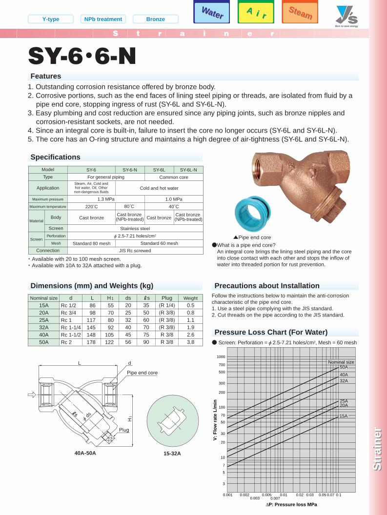
SY-6・6-NFeatures
1. Outstanding corrosion resistance offered by bronze body.2. Corrosive portions, such as the end faces of lining steel piping or threads, are isolated from fluid by a
pipe end core, stopping ingress of rust (SY-6L and SY-6L-N).3. Easy plumbing and cost reduction are ensured since any piping joints, such as bronze nipples and
corrosion-resistant sockets, are not needed.4. Since an integral core is built-in, failure to insert the core no longer occurs (SY-6L and SY-6L-N).5. The core has an O-ring structure and maintains a high degree of air-tightness (SY-6L and SY-6L-N).
Specifications
ModelType
Application
Maximum pressure
Maximum temperature
Connection
Perforation
Mesh
SY-6 SY-6-N SY-6L-N
Stainless steelφ 2.5-7.21 holes/cm2
JIS Rc screwed
SY-6LFor general piping
1.3 MPa 1.0 MPa40˚C220˚C�
Cast bronze�
Standard 80 mesh
Cast bronze
80˚C�
Cast bronze (NPb-treated)
Cold and hot water
Common coreSteam, Air, Cold andhot water, Oil, Othernon-dangerous fluids
Screen
MaterialCast bronze
(NPb-treated)
Standard 60 mesh
Body
Screen
Dimensions (mm) and Weights (kg)
Nominal size15A20A25A32A40A50A
Weight0.50.81.11.92.63.8
dRc 1/2Rc 3/4Rc 1Rc 1-1/4Rc 1-1/2Rc 2
L8698
117145148178
55708092
105122
H1 ds202532404556
Rs355060707590
Plug(R 1/4)�(R 3/8)(R 3/8)(R 3/8)R 3/8R 3/8
H1
φ ds
L d
Plug
Pipe end core
s
3
5
7
10
20
30
50
70
100
200
300
500
700
1000
0.001 0.0020.003
0.005 0.01 0.02 0.03 0.05 0.07 0.10.007
40A32A
25A20A
50A
V: F
low
rate
L/m
in
Nominal size
15A
∆P: Pressure loss MPa
Pressure Loss Chart (For Water)
Precautions about Installation
・ Available with 20 to 100 mesh screen.・ Available with 10A to 32A attached with a plug.
● Screen: Perforation =φ2.5-7.21 holes/cm2, Mesh = 60 mesh
●What is a pipe end core?An integral core brings the lining steel piping and the coreinto close contact with each other and stops the inflow ofwater into threaded portion for rust prevention.
Follow the instructions below to maintain the anti-corrosioncharacteristic of the pipe end core.1. Use a steel pipe complying with the JIS standard.2. Cut threads on the pipe according to the JIS standard.
▲Pipe end core
40A-50A
SteamSteam
Bronze
15-32A
P149-150_スト 2011.3.10 1:47 PM ページ 2
Y-type Stainless steel
S t r a i n e r
Str
ain
erS
trai
ner
7-3, Futano-cho, Mizuho-ku, Nagoya, 467-0861, Japan Phone: 81-52-881-7199 Fax: 81-52-881-7201www.yoshitake.jp
151
スト-05
SteamSteam A i r
A i rWaterWater
SteamSteam A i r
A i rWaterWater
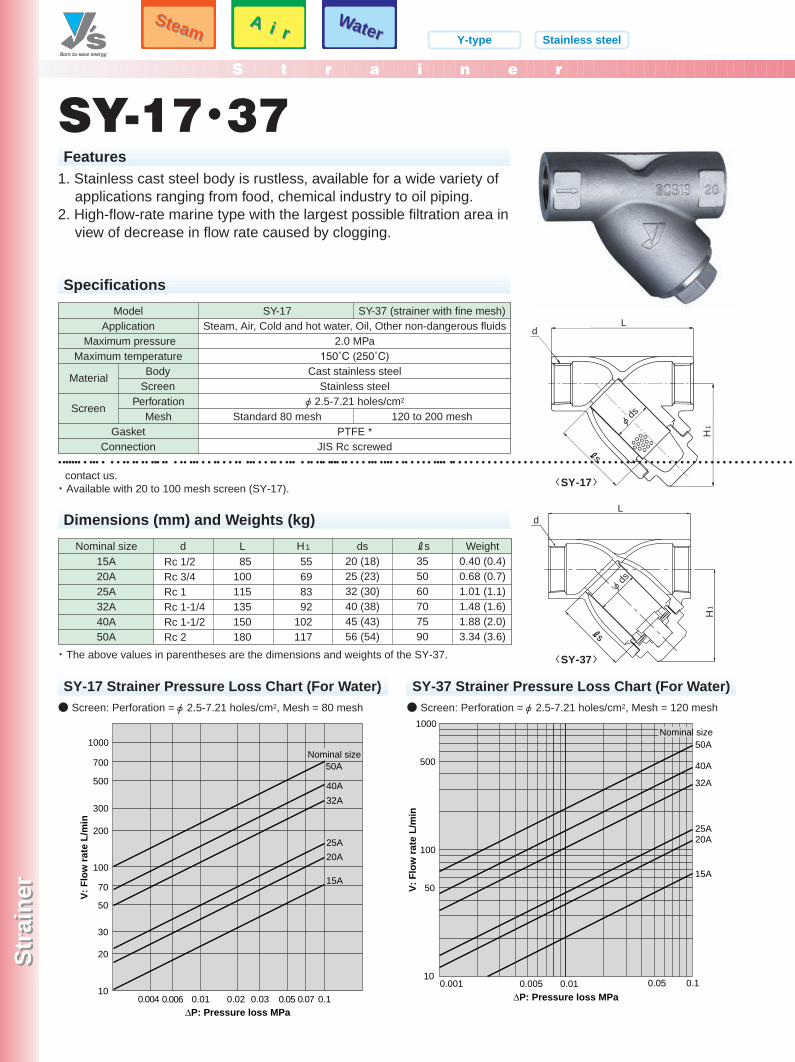
SY-17・37Features
1. Stainless cast steel body is rustless, available for a wide variety ofapplications ranging from food, chemical industry to oil piping.
2. High-flow-rate marine type with the largest possible filtration area inview of decrease in flow rate caused by clogging.
Specifications
SY-17
Standard 80 mesh
ModelApplication
Maximum pressureMaximum temperature
PerforationMesh
GasketConnection
SY-37 (strainer with fine mesh)
120 to 200 mesh
Steam, Air, Cold and hot water, Oil, Other non-dangerous fluids2.0 MPa
150˚C (250˚C)Cast stainless steel
Stainless steelφ 2.5-7.21 holes/cm2
PTFE *JIS Rc screwed
Screen
Material BodyScreen
Dimensions (mm) and Weights (kg)
Nominal size15A20A25A32A40A50A
Weight0.40 (0.4)0.68 (0.7)1.01 (1.1)1.48 (1.6)1.88 (2.0)3.34 (3.6)
d L85
100115135150180
55698392
102117
H1 ds20 (18)25 (23)32 (30)40 (38)45 (43)56 (54)
Rs355060707590
Rc 1/2Rc 3/4Rc 1Rc 1-1/4Rc 1-1/2Rc 2
Ld
φ ds
H1
s
10
20
30
50
70
100
200
300
500
700
1000
0.004 0.006 0.01 0.02 0.03 0.05 0.07 0.1
50A
40A32A
25A
15A
20A
V: F
low
rate
L/m
in
∆P: Pressure loss MPa
Nominal size
0.001 0.005 0.0110
100
50
500
1000
0.05 0.1
50A
40A
32A
25A20A
15A
V: F
low
rate
L/m
in
Nominal size
∆P: Pressure loss MPa
SY-17 Strainer Pressure Loss Chart (For Water)
••••••• • ••• • • • •• •• •• ••• •• • •• ••• • • •• • • •• ••• • • •• • ••• • •• ••• •••• •• • • • ••• •••• • •• • • • • •••• •• • • • • • • • • • • • • • • • • • • • • • • • • • • • • • • • • • • • • • • • • • • • • • • • • • • • • • • • • • • • • • • • • • • • • • • • • • • • • • • • • • • • • • • • • • • •contact us.・ Available with 20 to 100 mesh screen (SY-17).
・ The above values in parentheses are the dimensions and weights of the SY-37.
● Screen: Perforation =φ2.5-7.21 holes/cm2, Mesh = 80 mesh
SY-37 Strainer Pressure Loss Chart (For Water)● Screen: Perforation =φ2.5-7.21 holes/cm2, Mesh = 120 mesh
〈SY-17〉
φ ds
Ld
H1
s
〈SY-37〉
スト ページ
S t r a i n e r
www.yoshitake.jp
スト-06
SY-40・40CH
1
φ ds
L
Rs
3000020000
10000
32
1
57
10
2030
5070
100
200300
500700
1000
20003000
50007000
50A40A32A
25A
15A
0.001 0.002 0.003 0.0050.007
0.01 0.02 0.03 0.05 0.07 0.1
20A
250A
150A
300A
Nominalsize
200A
125A100A
65A80A
V: F
low
rate
L/m
in
∆P: Pressure loss MPa
● φ
SY-40
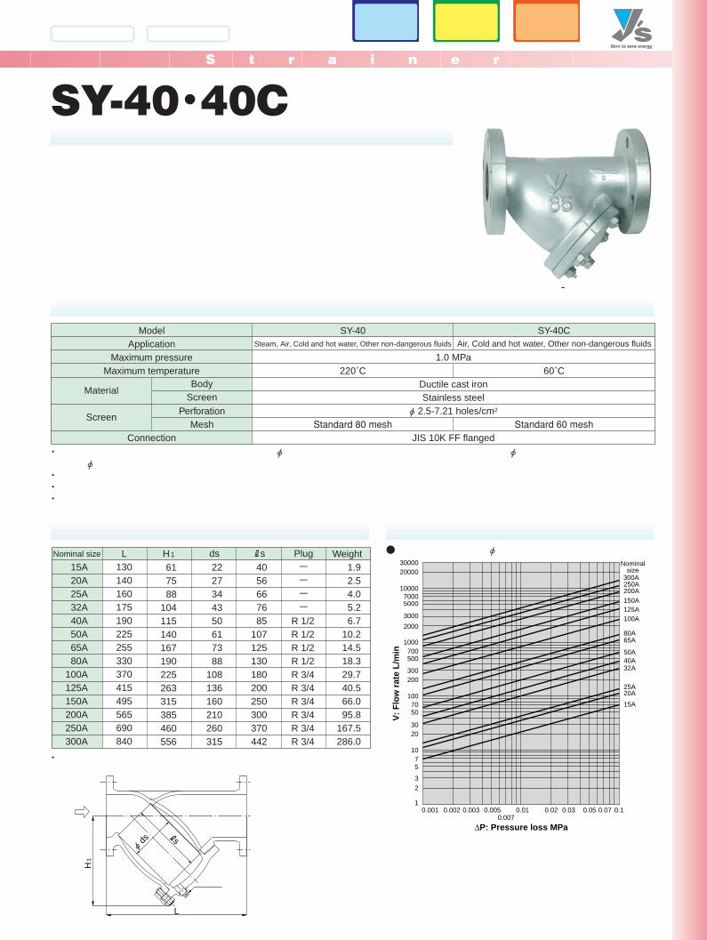
220˚C����
Standard 80 mesh
ModelApplication
Maximum pressureMaximum temperature
PerforationMesh
Connection
SY-40C
60˚C����
Standard 60 mesh
1.0 MPa
Ductile cast ironStainless steel
φ 2.5-7.21 holes/cm2
JIS 10K FF flanged
Screen
Material
Steam, Air, Cold and hot water, Other non-dangerous fluids Air, Cold and hot water, Other non-dangerous fluids
BodyScreen
Nominal size Weight L130140160175190225255330370415495565690840
H1
617588
104115140167190225263315385460556
2227344350617388
108136160210260315
4056667685
107125130180200250300370442
1.92.54.05.26.7
10.214.518.329.740.566.095.8
167.5286.0
ds Rs Plug-�-�-�-�
R 1/2R 1/2R 1/2R 1/2R 3/4R 3/4R 3/4R 3/4R 3/4R 3/4
15A20A25A32A40A50A65A80A
100A125A150A200A250A300A
・ φ φφ
・・・
-
・
スト ページ
Nominal size
15A20A25A32A40A50A65A80A
100A125A150A
130150160180200230290310350400480
130 (ー)140 (ー)160 (160)175 (180)190 (200)233 (230)290 (302)316 (330)360 (370)415 (440)495 (520)
617588
104115140167190225263315
2227344350617388
108136160
4056667685
107125130180200250
ーーーーR 1/2R 1/2R 1/2R 1/2R 3/4R 3/4R 3/4
2.0 3.0 4.5 5.5 8.010.514.018.027.040.066.0
1.9 (ー)2.5 (ー)4.0 (4.5)5.2 (6.0)6.7 (8.5)
10.2 (11.0)15.0 (15.0)19.0 (20.0)28.0 (30.0)42.0 (43.0)68.0 (71.0)
LH1 ds Rs Plug
SY-40ENSY-40EN SY-40HWeight
SY-40H
・ Available with 20 to 100 mesh screen (perforation: φ2.5-7.21 holes/cm2) or only with perforration (15A to 80A: φ1.3-16.2 holes/cm2, 100A or more: φ1.5-11.2 holes/cm2).・ Available with a brass plug (the standard is S15C or FCMB310).
Y-type Ductile iron
S t r a i n e r
Str
ain
erS
trai
ner
7-3, Futano-cho, Mizuho-ku, Nagoya, 467-0861, Japan Phone: 81-52-881-7199 Fax: 81-52-881-7201
www.yoshitake.jp153
スト-07
SteamSteam A i r
A i rWaterWater
SteamSteam A i r
A i rWaterWater
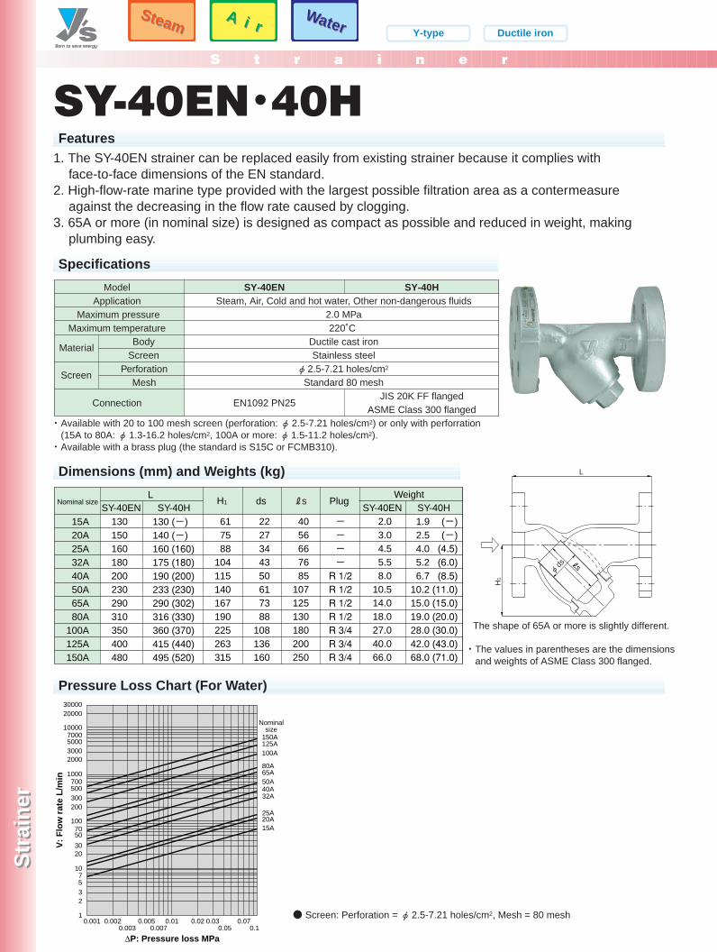
SY-40EN・40HFeatures
H1
L
φ ds
50A40A32A
25A
15A20A
150A
Nominalsize
125A100A
65A80A
3000020000
10000
32
1
57
10
2030
5070
100
200300500700
1000
2000300050007000
V:
Flo
w r
ate
L/m
in
0.001 0.0020.003
0.0050.007
0.01 0.02 0.030.05
0.070.1
∆P: Pressure loss MPa
Pressure Loss Chart (For Water)
1. The SY-40EN strainer can be replaced easily from existing strainer because it complies withface-to-face dimensions of the EN standard.
2. High-flow-rate marine type provided with the largest possible filtration area as a contermeasureagainst the decreasing in the flow rate caused by clogging.
3. 65A or more (in nominal size) is designed as compact as possible and reduced in weight, makingplumbing easy.
Specifications
SY-40EN
EN1092 PN25
ModelApplication
Maximum pressureMaximum temperature
PerforationMesh
Connection
SY-40H
JIS 20K FF flangedASME Class 300 flanged
Steam, Air, Cold and hot water, Other non-dangerous fluids2.0 MPa220˚C
Ductile cast ironStainless steel
φ 2.5-7.21 holes/cm2
Standard 80 meshScreen
MaterialBody
Screen
Dimensions (mm) and Weights (kg)
・ The values in parentheses are the dimensionsand weights of ASME Class 300 flanged.
The shape of 65A or more is slightly different.
● Screen: Perforation = φ2.5-7.21 holes/cm2, Mesh = 80 mesh
P153-154_スト 2011.3.15 1:19 PM ページ 1
S t r a i n e r
www.yoshitake.jp
スト-08
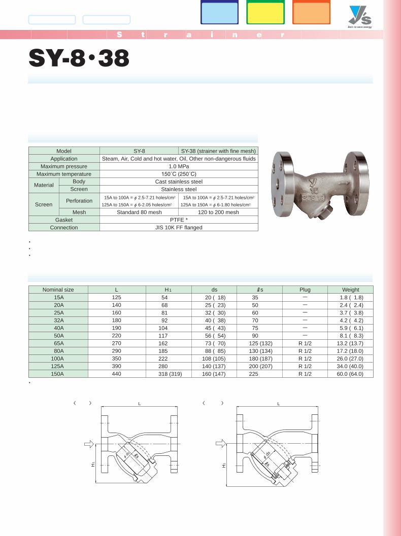
SY-8・38
SY-8
Standard 80 mesh
ModelApplication
Maximum pressureMaximum temperature
Perforation
MeshGasket
Connection
SY-38 (strainer with fine mesh)
120 to 200 mesh
Steam, Air, Cold and hot water, Oil, Other non-dangerous fluids1.0 MPa
150˚C (250˚C)Cast stainless steel
Stainless steel
PTFE *JIS 10K FF flanged
Screen
Material
15A to 100A = φ 2.5-7.21 holes/cm2
125A to 150A = φ 6-1.80 holes/cm2
15A to 100A = φ 2.5-7.21 holes/cm2
125A to 150A = φ 6-2.05 holes/cm2
BodyScreen
Nominal size WeightL125140160180190220270290350390440
H1
54 68 81 92104117162185222280318 (319)
20 ( 18)25 ( 23)32 ( 30)40 ( 38)45 ( 43)56 ( 54)73 ( 70)88 ( 85)
108 (105)140 (137)160 (147)
35 50 60 70 75 90125 (132)130 (134)180 (187)200 (207)225
1.8 ( 1.8)2.4 ( 2.4)3.7 ( 3.8)4.2 ( 4.2)5.9 ( 6.1)8.1 ( 8.3)
13.2 (13.7)17.2 (18.0)26.0 (27.0)34.0 (40.0)60.0 (64.0)
ds Rs Plug-�-�-�-�-�-�
R 1/2R 1/2R 1/2R 1/2R 1/2
15A20A25A32A40A50A65A80A
100A125A150A
・・・
H1
L
φ ds s
H1
L
s
φ ds
・
〈 〉 〈 〉
スト ページ
S t r a i n e r
Str
ain
erS
trai
ner
7-3, Futano-cho, Mizuho-ku, Nagoya, 467-0861, Japan Phone: 81-52-881-7199 Fax: 81-52-881-7201
www.yoshitake.jp155
スト-09
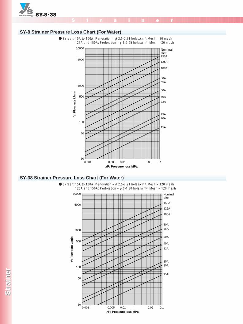
SY-8・38
50A
40A
32A
25A
15A
20A
150A
125A
100A
65A80A
Nominalsize
0.001 0.005 0.01 0.10.05
∆P: Pressure loss MPa
100
10
50
500
1000
5000
10000
V:
Flo
w r
ate
L/m
in
50A
40A
32A
25A
15A
20A
150A
125A
100A
65A
80A
10
100
50
500
1000
5000
10000
0.001 0.10.050.010.005
V:
Flo
w r
ate
L/m
in
Nominalsize
∆P: Pressure loss MPa
SY-8 Strainer Pressure Loss Chart (For Water)● Screen: 15A to 100A: Perforation =φ2.5-7.21 holes/cm2, Mesh = 80 mesh
125A and 150A: Perforation =φ6-2.05 holes/cm2, Mesh = 80 mesh
SY-38 Strainer Pressure Loss Chart (For Water)● Screen: 15A to 100A: Perforation =φ2.5-7.21 holes/cm2, Mesh = 120 mesh
125A and 150A: Perforation =φ6-1.80 holes/cm2, Mesh = 120 mesh
P155-156_スト 2011.3.10 1:49 PM ページ 1
S t r a i n e r
www.yoshitake.jp
スト-10
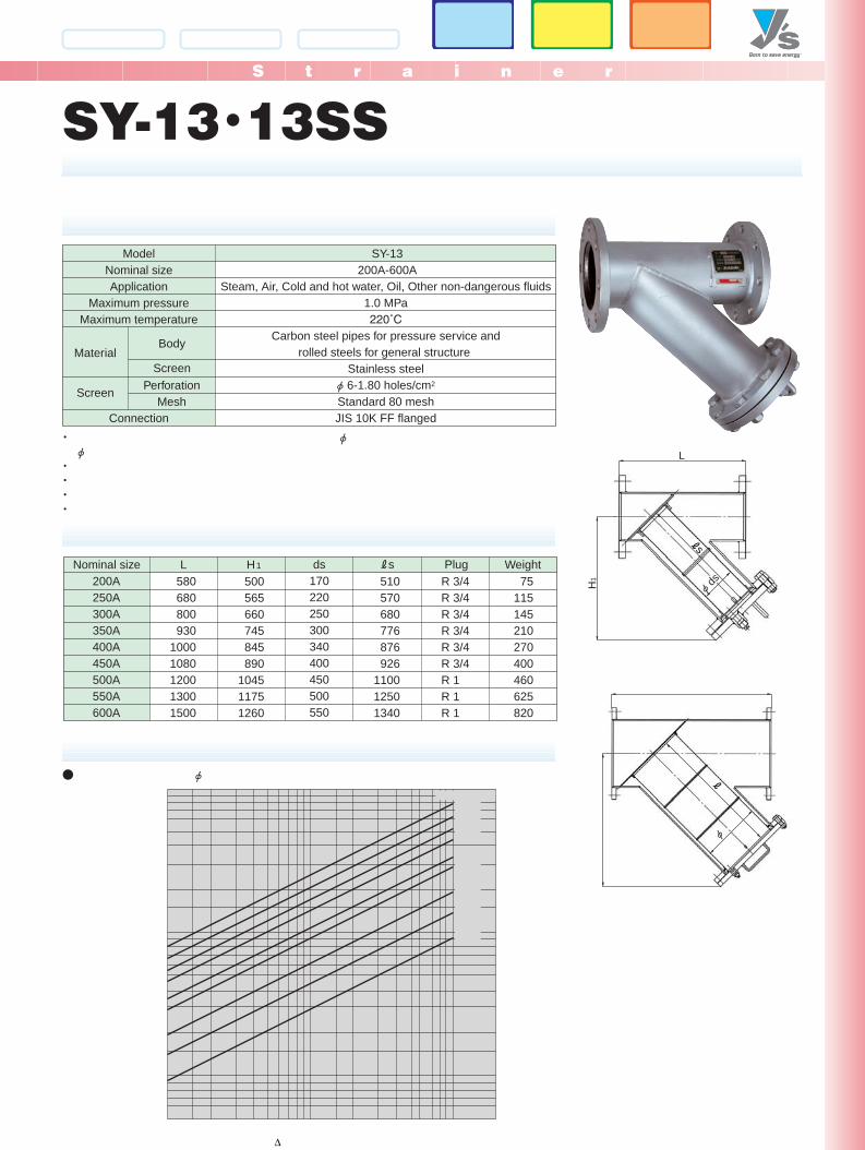
SY-13・13SS
SY-13200A-600A
ModelNominal sizeApplication
Maximum pressureMaximum temperature
PerforationMesh
Connection
Steam, Air, Cold and hot water, Oil, Other non-dangerous fluids1.0 MPa220˚C
Carbon steel pipes for pressure service androlled steels for general structure
Stainless steelφ 6-1.80 holes/cm2
Standard 80 meshJIS 10K FF flanged
Screen
MaterialBody
Screen
L
H1
φ ds
s
φ
Nominal size WeightL H1
500565660745845890
104511751260
510570680776876926
110012501340
75115145210270400460625820
580680800930
10001080120013001500
ds170220250300340400450500550
Rs PlugR 3/4R 3/4R 3/4R 3/4R 3/4R 3/4R 1R 1R 1
200A250A300A350A400A450A500A550A600A
∆
・ φφ
・・・・
● φ
スト ページ
S t r a i n e r
www.yoshitake.jp
スト-13
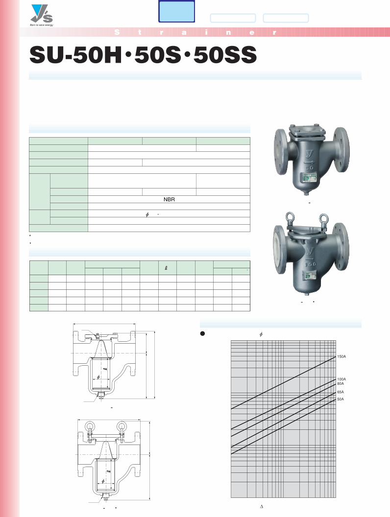
SU-50H・50S・50SS
����
NBR�
φ -
-
- ・
* ・
R ・�
∆
150A
100A80A
65A
50A
φ
-
φ
- ・
● φ
スト ページ
S t r a i n e r
www.yoshitake.jp
スト-14
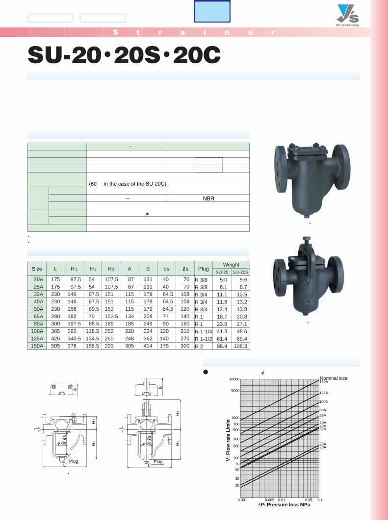
SU-20・20S・20C
-
-
・
�(60 in the case of the SU-20C)�
�ー�
���
NBR����
φ
・・
Size L
175175230230230290300365425505
B
131131179179179208249334362414
A
8787
115115115134185220248305
7070
108108120140160210270300
5.06.1
11.111.812.418.723.841.361.498.4
5.66.7
12.513.213.820.827.148.669.4
108.3
H1
97.597.5
146146156182197.5262340.5378
H2
545467.567.569.57088.5
118.5134.5158.5
404064.564.564.57790
120140175
H3
107.5107.5151151153153.5189253269293
ds Rs PlugSU-20 SU-20S
20A25A32A40A50A65A80A
100A125A150A
R 3/8R 3/8R 3/4R 3/4R 3/4R 1R 1R 1-1/4R 1-1/2R 2
Weight
20
30
5070
100
200
300
500700
1000
5000
10000
0.001 0.005 0.01 0.05 0.1
20A
150A
25A
40A
100A
65A
32A
80A
125A
50A
V: F
low
rate
L/m
in
∆P: Pressure loss MPa
Nominal size● φ
H1
A
H2
L
φ ds
Plug
s
・
B
H3
H1
L
φ ds
s
Plug
スト ページ
Basket Ductile iron
S t r a i n e r
Str
ain
erS
trai
ner
7-3, Futano-cho, Mizuho-ku, Nagoya, 467-0861, Japan Phone: 81-52-881-7199 Fax: 81-52-881-7201
www.yoshitake.jp159
スト-15
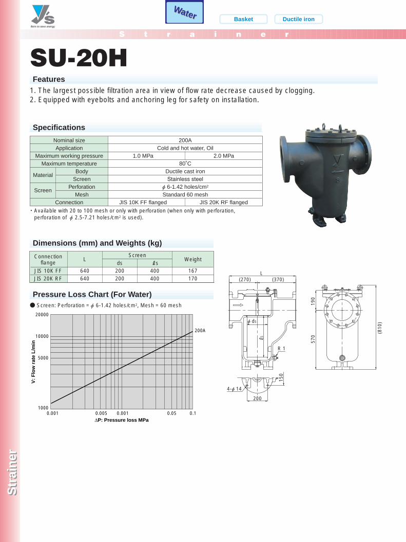
WaterWaterWaterWater
SU-20HFeatures
1. The largest possible filtration area in view of flow rate decrease caused by clogging.2. Equipped with eyebolts and anchoring leg for safety on installation.
Specifications
Nominal sizeApplication
Maximum working pressureMaximum temperature
BodyScreen
PerforationMesh
Connection
200ACold and hot water, Oil
80˚CDuctile cast ironStainless steel
φ 6-1.42 holes/cm2
Standard 60 mesh
1.0 MPa
JIS 10K FF flanged
2.0 MPa
JIS 20K RF flanged
Material
Screen
Dimensions (mm) and Weights (kg)
Connectionflange
JIS 10K FFJIS 20K RF
Weight
200200
167170
640640
LScreen
ds Rs400400
20000
10000
5000
10000.001 0.005 0.001 0.05 0.1
200A
V:
Flo
w r
ate
L/m
in
∆P: Pressure loss MPa
(810
)
190
570
R 1
φ dS
150
200
4-φ 14
(270) (370)L
S
Pressure Loss Chart (For Water)
・ Available with 20 to 100 mesh or only with perforation (when only with perforation,perforation of φ2.5-7.21 holes/cm2 is used).
● Screen: Perforation =φ6-1.42 holes/cm2, Mesh = 60 mesh
P159-160_スト 2011.3.10 1:51 PM ページ 1

S t r a i n e r
Str
ain
erS
trai
ner
7-3, Futano-cho, Mizuho-ku, Nagoya, 467-0861, Japan Phone: 81-52-881-7199 Fax: 81-52-881-7201
www.yoshitake.jp160
スト-16
Nominal size L
620660710760810860910960
10101060
273295330350400430455480510545
882106212181306149216552195235325382716
687867
10211103125314051945210722372419
440570670710810910
1400151015901720
------800840920970
------19232727
210240290340390440490540590630
375505600640740835930
103011001220
A H1 h1CHH0 dsDrainplug
VentplugRs
200A250A300A350A400A450A500A550A600A650A
R 1R 1R 1R 1R 1R 1R 1R 1R 1-1/2R 1-1/2
R 1/2R 1/2R 1/2R 3/4R 3/4R 3/4R 3/4R 3/4R 1R 1
SU-6・6SS・6ASFeatures
1. Used mainly for cooling water and industrial water for dustprevention.
2. Designed for large-diameter piping and lighter than cast ironstrainer.
Specifications
Dimensions (mm) and Weights (kg)
Pressure Loss Chart (For Water) Vent plug
Drain plug
s
SU-6 200A-450A
ApplicationNominal size
Maximum pressureMaximum temperature
Perforation
MeshConnection
Cold and hot water, Oil, Other non-dangerous fluids200A-650A
1.0 MPa120˚C
Rolled steel for carbon steel piping and general structural rolled steel
Stainless steelφ 10-0.8 holes/cm2
Standard 40 meshJIS 10K FF flanged
Screen
MaterialBody
Screen
・ Available with 20 to 100 mesh screen.・ Available with rust-proof (hot-dip zinc coating).・ Available with stainless steel wetted parts (SU-6SS).・ Available with all stainless steel made (SU-6AS).
L
φ ds
4-φ h1
φ c
A
H1
HH
0
Drain plug
Bent plug
s
SU-6 500A-650A
650A
600A
550A
500A
450A
400A
350A
300A
250A
200A
V:
Flo
w r
ate
m3 /
h
Nominal size
∆P: Pressure loss MPa
50000
5000
1000
100000
10000
0.001 0.005 0.01 0.05 0.1
● Screen: Perforation = φ10-0.8 holes/cm2, Mesh = 40 mesh
Basket Carbon steel
WaterWaterStainless steel
P159-160_スト 2011.3.17 10:45 AM ページ 2
S t r a i n e r
Str
ain
erS
trai
ner
7-3, Futano-cho, Mizuho-ku, Nagoya, 467-0861, Japan Phone: 81-52-881-7199 Fax: 81-52-881-7201
www.yoshitake.jp161
スト-19
WaterWaterWaterWater Duplex Ductile iron
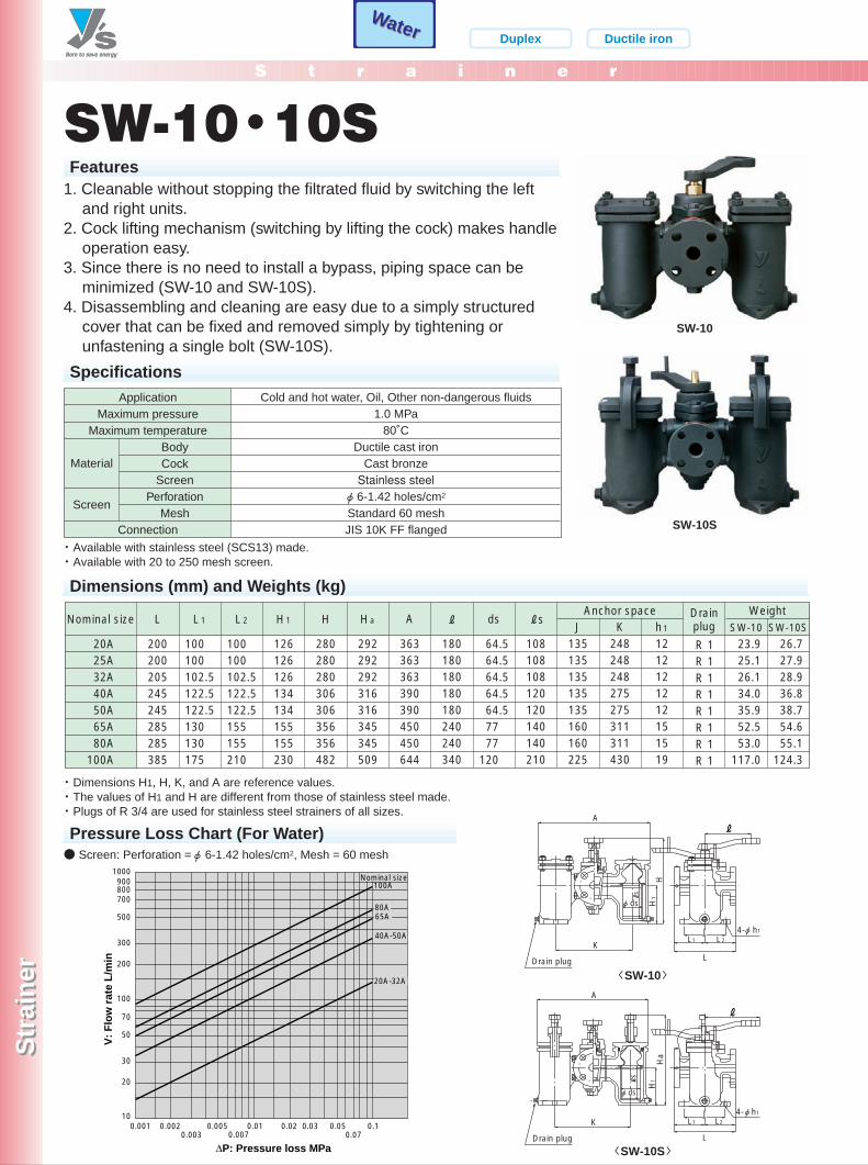
SW-10・10SFeatures
1. Cleanable without stopping the filtrated fluid by switching the leftand right units.
2. Cock lifting mechanism (switching by lifting the cock) makes handleoperation easy.
3. Since there is no need to install a bypass, piping space can beminimized (SW-10 and SW-10S).
4. Disassembling and cleaning are easy due to a simply structuredcover that can be fixed and removed simply by tightening orunfastening a single bolt (SW-10S).
SW-10
SW-10S
SpecificationsApplication
Maximum pressureMaximum temperature
BodyCock
ScreenPerforation
MeshConnection
Cold and hot water, Oil, Other non-dangerous fluids1.0 MPa
80˚CDuctile cast iron
Cast bronzeStainless steel
φ 6-1.42 holes/cm2
Standard 60 meshJIS 10K FF flanged
Material
Screen
Dimensions (mm) and Weights (kg)
Nominal size L
200200205245245285285385
126126126134134155155230
280280280306306356356482
292292292316316345345509
363363363390390450450644
180180180180180240240340
108108108120120140140210
135135135135135160160225
248248248275275311311430
1212121212151519
AJ K h1
23.925.126.134.035.952.553.0
117.0
26.727.928.936.838.754.655.1
124.3
H1L1
64.564.564.564.564.57777
120
H Ha
100100102.5122.5122.5130130175
L2
100100102.5122.5122.5155155210
ds RsRDrainplug SW-10 SW-10S
20A25A32A40A50A65A80A
100A
R 1R 1R 1R 1R 1R 1R 1R 1
WeightAnchor space
H1
H
L
L1
4-φ h1
L2
A
K
φ ds
J
Drain plug
s
10
30
20
50
70
100
200
300
500
900
700800
1000
0.001 0.0020.003
0.005 0.01 0.02 0.03 0.050.07
0.10.007
100A
65A80A
V:
Flo
w r
ate
L/m
in
20A-32A
Nominal size
∆P: Pressure loss MPa
40A-50A
Pressure Loss Chart (For Water)
・ Available with stainless steel (SCS13) made.・ Available with 20 to 250 mesh screen.
・ Dimensions H1, H, K, and A are reference values.・ The values of H1 and H are different from those of stainless steel made.・ Plugs of R 3/4 are used for stainless steel strainers of all sizes.
● Screen: Perforation =φ6-1.42 holes/cm2, Mesh = 60 mesh
H1
Ha
L
L1 L2
4-φ h1
A
KJ
Drain plug
s
φ ds
〈SW-10S〉
〈SW-10〉
P161-162_スト 2011.3.10 1:52 PM ページ 1

S t r a i n e r
Str
ain
erS
trai
ner
7-3, Futano-cho, Mizuho-ku, Nagoya, 467-0861, Japan Phone: 81-52-881-7199 Fax: 81-52-881-7201
www.yoshitake.jp162
スト-20
FeatureModel
Picture
Application
Y type screwed / Easy plugSY-9
Air, Cold and hot water, Other non-dangerous fluids
Y type screwed / BronzeSY-24
MaterialCast bronze
Leadless bronzeSY-24-N
Cold and hot water
1.6 MPa80˚C
Inlet: JIS Rc screwed Outlet: JIS R screwed
Stainless steel60 mesh
(φ2.5-7.21 holes/cm2)20-100 mesh
(φ 2.5-7.21 holes/cm2)15A-50A
Cast bronze (NPb-treated)
1.0 MPa80˚C
JIS Rc screwedDuctile cast ironStainless steel
60 mesh(φ 2.5-7.21 holes/cm2)
20-100 mesh(φ 2.5-7.21 holes/cm2)
15A-50A-
Max. pressureMax. temperature
ConnectionBody
Screen
Standard screen
Available screen
Size Others - -
FeatureModel
Picture
Application
Y type flanged / Carbon steelSY-20
Steam, Air, Cold and hot water,Other non-dangerous fluids
SY-10
Steam, Air, Cold and hot water,Other non-dangerous fluids
Material
3.0 MPa260˚C *
JIS 30K RF flanged
15A-250A
SY-10H
High-pressure gas, Steam, Cold and
hot water, Other non-dangerous fluids
1.0, 2.0 or 3.0 MPa350˚C *
JIS 10K RF flangedJIS 20K RF flangedJIS 30K RF flanged
15A-100A
1.0 or 2.0 MPa260˚C
JIS 10K RF flangedJIS 20K RF flanged
Cast carbon steelStainless steel
80 mesh(φ 6-1.80 holes/cm2)
20-60 mesh(φ 6-1.80 holes/cm2)
15A-150A
Max. pressureMax. temperature
Connection
BodyScreen
Standard screen
Available screen
Size
Others* If the temperature is more than260˚C, please contact us.
* For SY-10H-30, 350˚C forworking pressure up to 2.0 MPa,and 300˚C for more than 2.0 MPa.
-
SY-24
SY-10
Y type flanged / Carbon steel
Cast carbon steelStainless steel
80 mesh(φ 6-1.80 holes/cm2)
20-100 mesh(φ 6-1.80 holes/cm2)
P161-162_スト 2011.3.10 1:52 PM ページ 2
S t r a i n e r
Str
ain
erS
trai
ner
7-3, Futano-cho, Mizuho-ku, Nagoya, 467-0861, Japan Phone: 81-52-881-7199 Fax: 81-52-881-7201
www.yoshitake.jp163
スト-XX
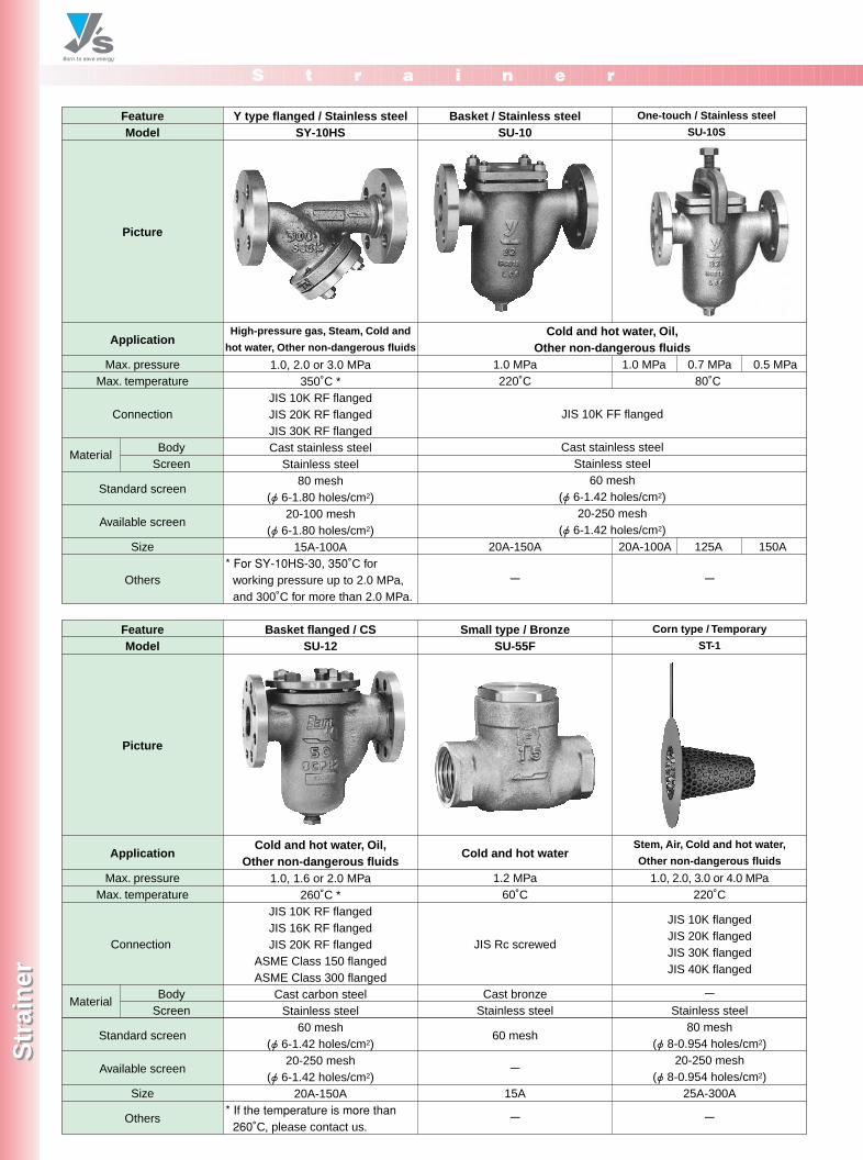
FeatureModel
Picture
Application
Y type flanged / Stainless steelSY-10HS
High-pressure gas, Steam, Cold and
hot water, Other non-dangerous fluids
Basket / Stainless steelSU-10
Cold and hot water, Oil,Other non-dangerous fluids
JIS 10K FF flanged
Cast stainless steelStainless steel
60 mesh(φ 6-1.42 holes/cm2)
20-250 mesh(φ 6-1.42 holes/cm2)
Material
1.0 MPa220˚C
20A-150A
One-touch / Stainless steel
SU-10S
1.0, 2.0 or 3.0 MPa350˚C *
JIS 10K RF flangedJIS 20K RF flangedJIS 30K RF flangedCast stainless steel
Stainless steel80 mesh
(φ 6-1.80 holes/cm2)20-100 mesh
(φ 6-1.80 holes/cm2)15A-100A
Max. pressureMax. temperature
Connection
BodyScreen
Standard screen
Available screen
Size
Others - -* For SY-10HS-30, 350˚C for
working pressure up to 2.0 MPa,and 300˚C for more than 2.0 MPa.
1.0 MPa 0.7 MPa 0.5 MPa80˚C
20A-100A 125A 150A
FeatureModel
Picture
Application
Basket flanged / CSSU-12
Cold and hot water, Oil,Other non-dangerous fluids
Small type / BronzeSU-55F
Cold and hot water
Material
1.2 MPa60˚C
JIS Rc screwed
Cast bronzeStainless steel
60 mesh
-
15A
Corn type / Temporary
ST-1
Stem, Air, Cold and hot water,
Other non-dangerous fluids
1.0, 1.6 or 2.0 MPa260˚C *
JIS 10K RF flangedJIS 16K RF flangedJIS 20K RF flanged
ASME Class 150 flangedASME Class 300 flanged
Cast carbon steelStainless steel
60 mesh(φ 6-1.42 holes/cm2)
20-250 mesh(φ 6-1.42 holes/cm2)
20A-150A
Max. pressureMax. temperature
Connection
BodyScreen
Standard screen
Available screen
Size
Others - -* If the temperature is more than260˚C, please contact us.
1.0, 2.0, 3.0 or 4.0 MPa220˚C
JIS 10K flangedJIS 20K flangedJIS 30K flangedJIS 40K flanged
-Stainless steel
80 mesh(φ 8-0.954 holes/cm2)
20-250 mesh(φ 8-0.954 holes/cm2)
25A-300A
P163-164_スト 2011.3.10 1:52 PM ページ 1


![Spirax Strainer[1]](https://img.dokumen.tips/doc/110x75/5477b71cb4af9f9c108b4912/spirax-strainer1.jpg)