Embed Size (px)
Citation preview
STORMWATER C.3 GUIDEBOOK Stormwater Quality Requirements for Development Applications
Fifth Edition October 20, 2010 Visit www.cccleanwater.org for updates.
Municipal Regional Permit
Edition

This page intentionally left blank.
Stormwater C.3 Guidebook
Contra Costa Clean Water Program Tom Dalziel, Interim Program Manager 925-313-2392 [email protected] This Guidebook is referenced in stormwater ordinances adopted by
Antioch Phil Hoffmeister 925-779-7035 [email protected] Brentwood Jagtar Dhaliwal 925-516-5128 [email protected] Clayton Laura Hoffmeister 925-673-7308 [email protected] Concord Libbey Bell 925-671-3394 [email protected] Danville Chris McCann 925-314-3342 [email protected] El Cerrito Garth Schultz 510-215-4351 [email protected]
Hercules Erwin Blancaflor 510-799-8242 [email protected] Lafayette Donna Feehan 925-934-3908 [email protected] Martinez Alex Stroup 925-372-3519 [email protected] Moraga Jill Mercurio 925-888-7025 [email protected] Oakley Frank Kennedy 925-932-7857 [email protected] Orinda Cathleen Terentieff 925-253-4251 [email protected]
Pinole Dean Allison 510-724-9010 [email protected] Pittsburg Jolan Longway 925-252-4803 [email protected] Pleasant Hill Rod Wui 925-671-5261 [email protected] Richmond Lynne Scarpa 510-307-8135 [email protected] San Pablo Karineh Samkian 510-215-3037 [email protected] San Ramon Steven Spedowfski 925-973-2653 [email protected]
Walnut Creek Rinta Perkins 925-256-3511 [email protected] Contra Costa County Rich Lierly 925-313-2348 [email protected] Contra Costa County Flood Control and Water Conservation District Paul Detjens 925-313-2394 [email protected]
Prepared with assistance from
Dan Cloak Environmental Consulting
Hydrograph Modification Management Plan consultants: Philip Williams & Associates and Brown & Caldwell
5TH EDITION — OCTOBER 20, 2010

This page intentionally left blank.
5th Edition — October 20, 2010 iii
Table of Contents
GLOSSARY
HOW TO USE THIS GUIDEBOOK 1► Plan Ahead to Avoid the Three Most Common Mistakes 2
CHAPTER 1. POLICIES AND PROCEDURES 3
Thresholds, Effective Dates, and Requirements ..................................... 3 ► The “50% Rule” for projects on Previously Developed Sites 3
Compliance Process at a Glance ............................................................. 5
Implementing C.3 on Phased Projects ..................................................... 6
Applying C.3 to New Subdivisions ........................................................... 7
Compliance with Flow-Control Requirements ......................................... 8
Alternative Compliance Options ............................................................ 10
CHAPTER 2. CONCEPTS AND CRITERIA 11
Water-Quality Regulations ..................................................................... 11 ► Maximum Extent Practicable 12 ► Best Management Practices 12
Hydrology for NPDES Compliance ......................................................... 13 ► Imperviousness 13 ► Sizing Requirements for Stormwater Treatment Facilities 14 ► Flow-Control (Hydrograph Modification Management) 15
Selection of Stormwater Treatment Facilities ...................................... 16 ► Harvesting, Use, Infiltration, and Evapotranspiration 16 ► Non-LID Treatment Facilities 19
Criteria for Infiltration Devices .............................................................. 20 ► Most LID Features and Facilities are Not Infiltration Devices 21
Environmental Benefit Perspective ....................................................... 21
CHAPTER 3. PREPARING YOUR STORMWATER CONTROL PLAN 23
Step by Step ............................................................................................ 25
Step 1: Assemble Needed Information .................................................. 25
C O N T R A C O S T A C L E A N W A T E R P R O G R A M
iv 5th Edition — October 20, 2010
Step 2: Identify Constraints & Opportunities ........................................ 26
Step 3: Prepare and Document Your LID Design .................................. 26
Step 4. Specify Source Control BMPs .................................................... 28 ► Identify Pollutant Sources 28 ► Note Locations on Stormwater Control Plan Exhibit 28 ► Prepare a Table and Narrative 28 ► Identify Operational Source Control BMPs 29
Step 5: Stormwater Facility Maintenance ............................................. 29
Step 6: Stormwater Control Plan Exhibit & Report ............................... 30 ► Coordination with Site, Architectural, and Landscaping Plans 30 ► Construction Plan C.3 checklist 31 ► Certification 32 ► Stormwater Control Plan Report Sample Outline and Contents 32 ► Stormwater Control Plan Template 34 ► Example Stormwater Control Plans 34
CHAPTER 4. LOW IMPACT DEVELOPMENT DESIGN GUIDE 35
Analyze Your Project for LID .................................................................. 36 ► Optimize the Site Layout 38 ► Use Pervious Surfaces 38 ► Disperse Runoff to Adjacent Pervious Areas 39 ► Store Runoff for Later use 39 ► Direct runoff to Integrated Management Practices 41
Develop and Document Your Drainage Design...................................... 43 ► Step 1: Delineate Drainage Management Areas 44 ► Step 2: Classify DMAs and determine runoff factors 44 ► Step 3: Tabulate Drainage Management AReas 48 ► Step 4: Select and Lay Out IMPs on Site Plan 49 ► Step 5: Calculate Minimum IMP Area and Volumes 49 ► Step 6: Determine if IMP Area and Volume are adequate 53 ► Step 7: Compute Maximum Orifice Flow Rate 54 Step 8: Complete Your Summary Report 55
Specify Preliminary Design Details........................................................ 57
Alternatives to LID Design ..................................................................... 57 ► Treatment Control Alternatives 58 ► Treatment and Flow Control Alternatives 59
CHAPTER 5. CONSTRUCTION OF INTEGRATED MANAGEMENT PRACTICES 93
What to Show on Construction Plans .................................................... 94 ► Grading is Key 94 ► Show how runoff moves 94 ► Show IMPs in Cross-Section 95
S T O R M W A T E R C . 3 . G U I D E B O O K
5th Edition — October 20, 2010 v
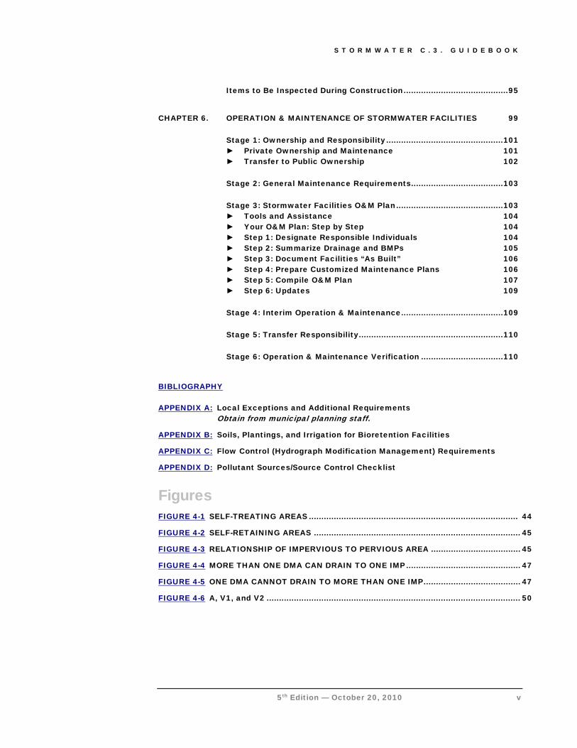
Items to Be Inspected During Construction .......................................... 95
CHAPTER 6. OPERATION & MAINTENANCE OF STORMWATER FACILITIES 99
Stage 1: Ownership and Responsibility ............................................... 101 ► Private Ownership and Maintenance 101 ► Transfer to Public Ownership 102
Stage 2: General Maintenance Requirements ..................................... 103
Stage 3: Stormwater Facilities O&M Plan ........................................... 103 ► Tools and Assistance 104 ► Your O&M Plan: Step by Step 104 ► Step 1: Designate Responsible Individuals 104 ► Step 2: Summarize Drainage and BMPs 105 ► Step 3: Document Facilities “As Built” 106 ► Step 4: Prepare Customized Maintenance Plans 106 ► Step 5: Compile O&M Plan 107 ► Step 6: Updates 109
Stage 4: Interim Operation & Maintenance ......................................... 109
Stage 5: Transfer Responsibility .......................................................... 110
Stage 6: Operation & Maintenance Verification ................................. 110 BIBLIOGRAPHY APPENDIX A: Local Exceptions and Additional Requirements
Obtain from municipal planning staff.
APPENDIX B: Soils, Plantings, and Irrigation for Bioretention Facilities
APPENDIX C: Flow Control (Hydrograph Modification Management) Requirements
APPENDIX D:
Figures
Pollutant Sources/Source Control Checklist
FIGURE 4-1 SELF-TREATING AREAS .................................................................................... 44
FIGURE 4-2 SELF-RETAINING AREAS ................................................................................... 45
FIGURE 4-3 RELATIONSHIP OF IMPERVIOUS TO PERVIOUS AREA .................................... 45
FIGURE 4-4 MORE THAN ONE DMA CAN DRAIN TO ONE IMP .............................................. 47
FIGURE 4-5 ONE DMA CANNOT DRAIN TO MORE THAN ONE IMP ....................................... 47
FIGURE 4-6 A, V1, and V2 ...................................................................................................... 50
C O N T R A C O S T A C L E A N W A T E R P R O G R A M
vi 5th Edition — October 20, 2010
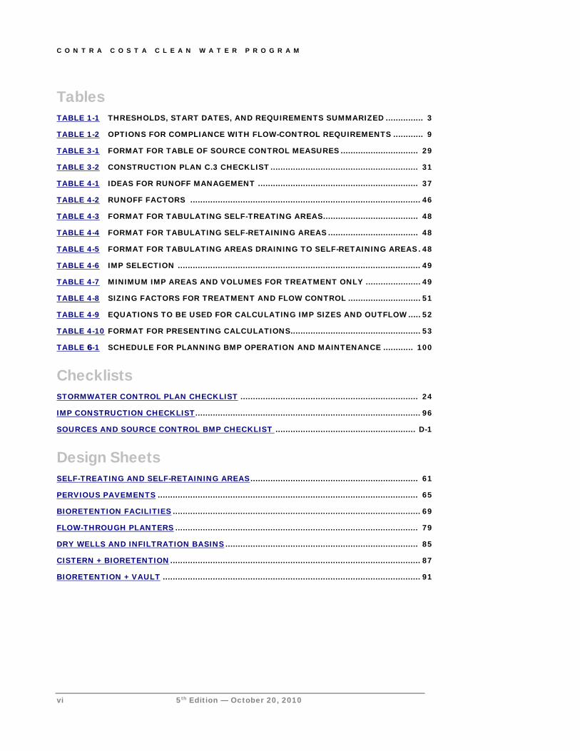
Tables TABLE 1-1 THRESHOLDS, START DATES, AND REQUIREMENTS SUMMARIZED ............... 3
TABLE 1-2 OPTIONS FOR COMPLIANCE WITH FLOW-CONTROL REQUIREMENTS ............ 9
TABLE 3-1 FORMAT FOR TABLE OF SOURCE CONTROL MEASURES ............................... 29
TABLE 3-2 CONSTRUCTION PLAN C.3 CHECKLIST ........................................................... 31
TABLE 4-1 IDEAS FOR RUNOFF MANAGEMENT ................................................................ 37
TABLE 4-2 RUNOFF FACTORS ............................................................................................ 46
TABLE 4-3 FORMAT FOR TABULATING SELF-TREATING AREAS ...................................... 48
TABLE 4-4 FORMAT FOR TABULATING SELF-RETAINING AREAS .................................... 48
TABLE 4-5 FORMAT FOR TABULATING AREAS DRAINING TO SELF-RETAINING AREAS . 48
TABLE 4-6 IMP SELECTION ................................................................................................. 49
TABLE 4-7 MINIMUM IMP AREAS AND VOLUMES FOR TREATMENT ONLY ...................... 49
TABLE 4-8 SIZING FACTORS FOR TREATMENT AND FLOW CONTROL ............................. 51
TABLE 4-9 EQUATIONS TO BE USED FOR CALCULATING IMP SIZES AND OUTFLOW ..... 52
TABLE 4-10 FORMAT FOR PRESENTING CALCULATIONS.................................................... 53
TABLE 6-1 SCHEDULE FOR PLANNING BMP OPERATION AND MAINTENANCE ............ 100
Checklists STORMWATER CONTROL PLAN CHECKLIST ....................................................................... 24
IMP CONSTRUCTION CHECKLIST .......................................................................................... 96
SOURCES AND SOURCE CONTROL BMP CHECKLIST
Design Sheets
........................................................ D-1
SELF-TREATING AND SELF-RETAINING AREAS ................................................................... 61
PERVIOUS PAVEMENTS ........................................................................................................ 65
BIORETENTION FACILITIES ................................................................................................... 69
FLOW-THROUGH PLANTERS ................................................................................................. 79
DRY WELLS AND INFILTRATION BASINS ............................................................................. 85
CISTERN + BIORETENTION .................................................................................................... 87
BIORETENTION + VAULT ....................................................................................................... 91

S T O R M W A T E R C . 3 . G U I D E B O O K
5th Edition — October 20, 2010 vii
Stormwater Glossary
Best Management Practice (BMP)
Any procedure or device designed to minimize the quantity of pollutants that enter the storm drain system or to control stormwater flow. See Chapter Two.
C.3
Provision in the Municipal Regional Permit. Requires the Permittees to use their planning authorities to include appropriate source control, site design, and stormwater treatment measures in new development and redevelopment projects to address pollutant discharges and prevent increases in runoff flows. Updates C.3 Provisions added to a preceding permit issued by the San Francisco Bay Water Board in February 2003.
C.3 Web Page http://www.cccleanwater.org/c3.html
California Stormwater Quality
Association (CASQA)
Publisher of the California Stormwater Best Management Practices Handbooks, available at www.cabmphandbooks.com.
California BMP Method
A method for determining the required volume of stormwater treatment facilities. Described in Section 5.5.1 of the California Stormwater Best Management Practice Manual (New Development) (CASQA, 2003).
Condition of Approval (COA)
Requirements a municipality may adopt for a project in connection with a discretionary action (e.g., adoption of an EIR or negative declaration or issuance of a use permit). COAs may specify features required to be incorporated into the final plans for the project and may also specify uses, activities, and operational measures that must be observed over the life of the project.
Contra Costa Clean Water Program
(CCCWP)
CCCWP is a collaboration established by an agreement among 19 Contra Costa cities and towns, Contra Costa County, and the Contra Costa County Flood and Water Conservation District. CCCWP implements common tasks and assists the member agencies to implement their local stormwater pollution prevention programs.
Design Storm A hypothetical rainstorm defined by rainfall intensities and durations.
Detention The practice of holding stormwater runoff in ponds, vaults, within berms, or in depressed areas and letting it discharge slowly to the storm drain system. See definitions of infiltration and retention.
Directly Connected Impervious Area
Any impervious surface which drains into a catch basin, area drain, or other conveyance structure without first allowing flow across pervious areas (e.g. lawns).
Direct Infiltration Infiltration via methods or devices, such as dry wells or infiltration trenches, designed to bypass unsaturated surface soils and transmit runoff directly to groundwater.
C O N T R A C O S T A C L E A N W A T E R P R O G R A M
viii 5th Edition — October 20, 2010
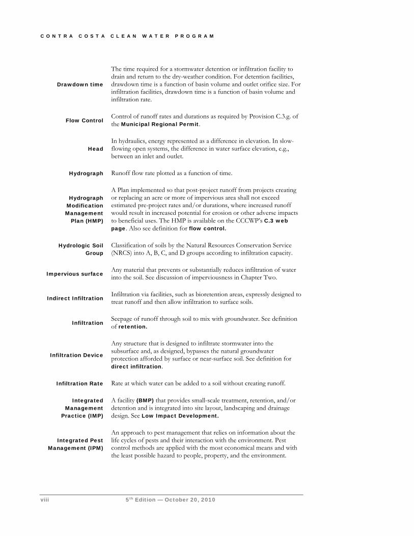
Drawdown time
The time required for a stormwater detention or infiltration facility to drain and return to the dry-weather condition. For detention facilities, drawdown time is a function of basin volume and outlet orifice size. For infiltration facilities, drawdown time is a function of basin volume and infiltration rate.
Flow Control Control of runoff rates and durations as required by Provision C.3.g. of the Municipal Regional Permit.
Head In hydraulics, energy represented as a difference in elevation. In slow-flowing open systems, the difference in water surface elevation, e.g., between an inlet and outlet.
Hydrograph Runoff flow rate plotted as a function of time.
Hydrograph Modification Management
Plan (HMP)
A Plan implemented so that post-project runoff from projects creating or replacing an acre or more of impervious area shall not exceed estimated pre-project rates and/or durations, where increased runoff would result in increased potential for erosion or other adverse impacts to beneficial uses. The HMP is available on the CCCWP’s C.3 web page. Also see definition for flow control.
Hydrologic Soil Group
Classification of soils by the Natural Resources Conservation Service (NRCS) into A, B, C, and D groups according to infiltration capacity.
Impervious surface Any material that prevents or substantially reduces infiltration of water into the soil. See discussion of imperviousness in Chapter Two.
Indirect Infiltration Infiltration via facilities, such as bioretention areas, expressly designed to treat runoff and then allow infiltration to surface soils.
Infiltration Seepage of runoff through soil to mix with groundwater. See definition of retention.
Infiltration Device
Any structure that is designed to infiltrate stormwater into the subsurface and, as designed, bypasses the natural groundwater protection afforded by surface or near-surface soil. See definition for direct infiltration.
Infiltration Rate Rate at which water can be added to a soil without creating runoff.
Integrated Management
Practice (IMP)
A facility (BMP) that provides small-scale treatment, retention, and/or detention and is integrated into site layout, landscaping and drainage design. See Low Impact Development.
Integrated Pest Management (IPM)
An approach to pest management that relies on information about the life cycles of pests and their interaction with the environment. Pest control methods are applied with the most economical means and with the least possible hazard to people, property, and the environment.
S T O R M W A T E R C . 3 . G U I D E B O O K
5th Edition — October 20, 2010 ix
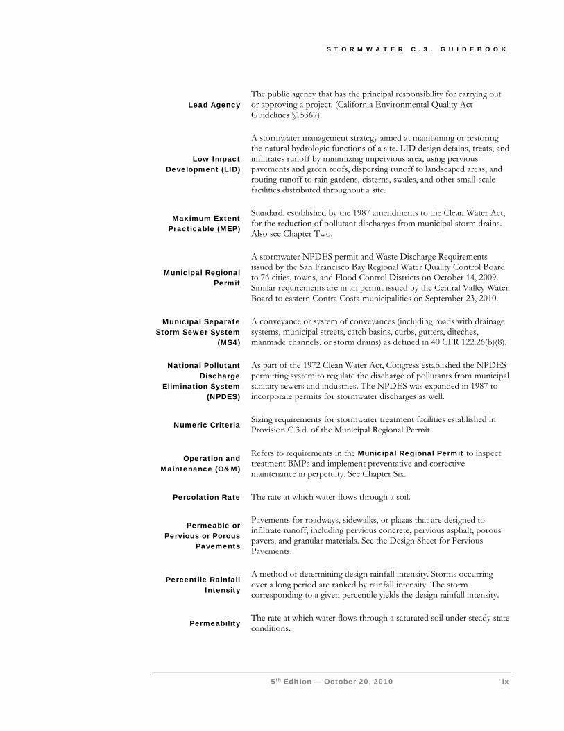
Lead Agency The public agency that has the principal responsibility for carrying out or approving a project. (California Environmental Quality Act Guidelines §15367).
Low Impact Development (LID)
A stormwater management strategy aimed at maintaining or restoring the natural hydrologic functions of a site. LID design detains, treats, and infiltrates runoff by minimizing impervious area, using pervious pavements and green roofs, dispersing runoff to landscaped areas, and routing runoff to rain gardens, cisterns, swales, and other small-scale facilities distributed throughout a site.
Maximum Extent Practicable (MEP)
Standard, established by the 1987 amendments to the Clean Water Act, for the reduction of pollutant discharges from municipal storm drains. Also see Chapter Two.
Municipal Regional Permit
A stormwater NPDES permit and Waste Discharge Requirements issued by the San Francisco Bay Regional Water Quality Control Board to 76 cities, towns, and Flood Control Districts on October 14, 2009. Similar requirements are in an permit issued by the Central Valley Water Board to eastern Contra Costa municipalities on September 23, 2010.
Municipal Separate Storm Sewer System
(MS4)
A conveyance or system of conveyances (including roads with drainage systems, municipal streets, catch basins, curbs, gutters, diteches, manmade channels, or storm drains) as defined in 40 CFR 122.26(b)(8).
National Pollutant Discharge
Elimination System (NPDES)
As part of the 1972 Clean Water Act, Congress established the NPDES permitting system to regulate the discharge of pollutants from municipal sanitary sewers and industries. The NPDES was expanded in 1987 to incorporate permits for stormwater discharges as well.
Numeric Criteria Sizing requirements for stormwater treatment facilities established in Provision C.3.d. of the Municipal Regional Permit.
Operation and Maintenance (O&M)
Refers to requirements in the Municipal Regional Permit to inspect treatment BMPs and implement preventative and corrective maintenance in perpetuity. See Chapter Six.
Percolation Rate The rate at which water flows through a soil.
Permeable or Pervious or Porous
Pavements
Pavements for roadways, sidewalks, or plazas that are designed to infiltrate runoff, including pervious concrete, pervious asphalt, porous pavers, and granular materials. See the Design Sheet for Pervious Pavements.
Percentile Rainfall Intensity
A method of determining design rainfall intensity. Storms occurring over a long period are ranked by rainfall intensity. The storm corresponding to a given percentile yields the design rainfall intensity.
Permeability The rate at which water flows through a saturated soil under steady state conditions.

C O N T R A C O S T A C L E A N W A T E R P R O G R A M
x 5th Edition — October 20, 2010
Pre-Project Conditions that exist on a development site immediately before the project to which municipal approvals apply.
Proprietary Stormwater
Treatment Facilities
Products designed and marketed by private businesses for treatment of stormwater. Many of these products do not meet requirements of the Municipal Regional Permit.
Rational Method A method of calculating runoff flows based on rainfall intensity, tributary area, and a factor representing the proportion of rainfall that runs off.
Regional Water Quality Control
Board (Regional Water Board or
RWQCB)
California RWQCBs are responsible for implementing pollution control provisions of the Clean Water Act and California Water Code within their jurisdiction. There are nine California RWQCBs. Western and central Contra Costa County are under the jurisdiction of the RWQCB for the San Francisco Bay Region; eastern Contra Costa County is under the jurisdiction of the RWQCB for the Central Valley Region.
Self-retaining area An area designed to retain runoff. Self-retaining areas may include graded depressions with landscaping or pervious pavements.
Self-treating area Natural, landscaped, or turf areas that drain overland off-site or to the storm drain system.
Source Control A facility or procedure to prevent pollutants from entering runoff.
Stormwater Control Plan
A plan specifying and documenting permanent features and facilities to control pollutants and stormwater flows for the life of the project.
Stormwater Control Operation &
Maintenance Plan
A plan detailing operation and maintenance requirements for stormwater treatment and flow-control facilities incorporated into a project.
Storm Water Pollution Prevention
Plan (SWPPP)
A plan providing for temporary measures to control sediment and other pollutants during construction.
Treatment Removal of pollutants from runoff, typically by filtration or settling.
WEF Method
A method for determining the minimum design volume of stormwater treatment facilities, recommended by the Water Environment Federation and American Society of Civil Engineers. Described in Urban Runoff Quality Management (WEF/ASCE, 1998).
Water Board See Regional Water Quality Control Board.
Water Quality Volume (WQV)
For stormwater treatment facilities that depend on detention to work, the volume of water that must be detained for a minimum specified drawdown time to achieve pollutant removal.
S T O R M W A T E R C . 3 . C O M P L I A N C E
5th Edition — October 20, 2010 1
How to Use this Guidebook Read the Overview to get a general understanding of the requirements. Then follow the step-by-step instructions to prepare your Stormwater Control Plan.
HIS Guidebook will help you ensure that your project complies with the C.3 requirements in the California Regional Water Quality Control Boards’ Municipal Regional Permit. The requirements are complex and technical. Most applicants will require the assistance of a qualified civil engineer,
architect, or landscape architect. Because every project is different, you should begin by scheduling a pre-application meeting with municipal planning staff.
To use the Guidebook, start by reviewing Chapter One to find out whether and how Provision C.3 applies to your project. Chapter One also provides an overview of the entire process of planning, design, construction, operation, and maintenance leading to compliance.
If there are terms and issues you find puzzling, look for answers in the glossary or in Chapter Two. Chapter Two provides background on key stormwater concepts and water quality regulations, including design criteria.
Then proceed to Chapter Three and follow the step-by-step guidance to prepare a Stormwater Control Plan for your site. The Stormwater Control Plan is submitted with your application for entitlements and development approvals.
Chapter Four, the Low Impact Development Design Guide, includes instructions for preparing and presenting your design and calculations. The calculations must be included in your Stormwater Control Plan to show compliance with permit requirements.
Start
T I C O N K E Y
Helpful Tip
Submittal Requirement
Terms to Look Up
References & Resources
C O N T R A C O S T A C L E A N W A T E R P R O G R A M
2 5th Edition — October 20, 2010
As you proceed with design and construction of your project, consult Chapter Five for guidance on preparing construction documents and overseeing construction of Low Impact Development features and facilities.
In Chapter Six you’ll find a detailed description of the process for ensuring operation and maintenance of your stormwater facilities over the life of the project. The chapter includes step-by-step instructions for preparing a Stormwater Facilities Operation and Maintenance Plan.
Throughout each Chapter, you’ll find references and resources to help you understand the regulations, complete your Stormwater Control Plan, and design stormwater control measures for your project.
The most recent version of the Guidebook, including updates and errata, is on the Contra Costa Clean Water Program website. The on-line Guidebook is in Adobe Acrobat format. If you are reading the Guidebook on a computer with an internet connection, you can use hyperlinks to navigate the document and to access various references. The hyperlinks are throughout the text, as well as in “References and Resources” sections (marked by the icon) and in the Bibliography. Some of these links (URLs) may be outdated. In that case, try entering portions of the title or other keywords into a web search.
► PLAN AHEAD TO AVOID THE THREE MOST COMMON MISTAKES
The most common (and costly) errors made by applicants for development approvals with respect to C.3 compliance are:
1. Not planning for C.3 compliance early enough. You should think about your strategy for C.3 compliance before completing a conceptual site design or sketching a layout of subdivision lots (Chapter 3).
2. Assuming proprietary stormwater treatment facilities will be adequate for compliance. A complete Low Impact Development design, including reuse, infiltration, evapotranspiration, or bioretention facilities, is now required for nearly all projects (Chapter 2).
3. Not planning for periodic inspections and maintenance of treatment and flow-control facilities. Consider who will own and who will maintain the facilities in perpetuity and how they will obtain access, and identify which arrangements are acceptable to your municipality (Chapter 6).
Local Requirements Cities, towns, or the County may
have requirements that differ from, or are in addition to, this county- wide Guidebook. See Appendix A
for local requirements.
Construction-Phase Controls
Your Stormwater Control Plan is a separate document from the Storm
Water Pollution Prevention Plan (SWPPP). A SWPPP provides for
temporary measures to control sediment and other pollutants
during construction at sites that disturb one acre or more. See the CCCWP website for information on requirements for construction-
phase controls.
S T O R M W A T E R C . 3 . C O M P L I A N C E
5th Edition — October 20, 2010 3
Policies and Procedures Determine if your development project must comply with the Municipal Regional Permit C.3 requirements, and review the steps to compliance.
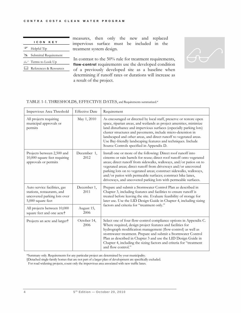
Thresholds, Effective Dates, and Requirements Table 1-1 (on following page) summarizes requirements for development projects. Thresholds are based on impervious area created or replaced in connection with a project. Interior remodels and routine maintenance or repair such as roof or exterior surface replacement and pavement resurfacing are excluded.
The 2010-2012 effective dates refer to the date on which a planning application has received final discretionary approval. At the discretion of local municipal staff, projects with applications that are deemed complete and diligently pursued prior to these dates may not have to meet all requirements (requirements in previous Guidebook editions may apply).
► THE “50% RULE” FOR PROJECTS ON PREVIOUSLY DEVELOPED SITES
Projects on previously developed sites may also need to retrofit drainage to provide treatment of runoff from all impervious areas of the entire site. For sites creating or replacing a total amount of impervious area greater than the applicable threshold (Table 1-1):
If the new project results in an alteration of more than 50% of the impervious surface of a previously existing development, and the existing development was not subject to stormwater treatment measures, then the entire project must be included in the treatment measure design.
If the new project results in an alteration of less than 50% of the impervious surface of a previously existing development, and the existing development was not subject to stormwater treatment
Chapter
1
C O N T R A C O S T A C L E A N W A T E R P R O G R A M
4 5th Edition — October 20, 2010
measures, then only the new and replaced impervious surface must be included in the treatment system design.
In contrast to the 50% rule for treatment requirements, flow-control requirements use the developed condition of a previously developed site as a baseline when determining if runoff rates or durations will increase as a result of the project.
I C O N K E Y
Helpful Tip
Submittal Requirement
Terms to Look Up
References & Resources
TABLE 1-1. THRESHOLDS, EFFECTIVE DATES, and Requirements summarized.*
Impervious Area Threshold Effective Date Requirement
All projects requiring municipal approvals or permits
May 1, 2010 As encouraged or directed by local staff, preserve or restore open space, riparian areas, and wetlands as project amenities, minimize land disturbance and impervious surfaces (especially parking lots) cluster structures and pavements, include micro-detention in landscaped and other areas, and direct runoff to vegetated areas. Use Bay-friendly landscaping features and techniques. Include Source Controls specified in Appendix D.
Projects between 2,500 and 10,000 square feet requiring approvals or permits
December 1, 2012
Install one or more of the following: Direct roof runoff into cisterns or rain barrels for reuse; direct roof runoff onto vegetated areas; direct runoff from sidewalks, walkways, and/or patios on to vegetated areas; direct runoff from driveways and/or uncovered parking lots on to vegetated areas; construct sidewalks, walkways, and/or patios with permeable surfaces; construct bike lanes, driveways, and uncovered parking lots with permeable surfaces.
Auto service facilities, gas stations, restaurants, and uncovered parking lots over 5,000 square feet
December 1, 2011
Prepare and submit a Stormwater Control Plan as described in Chapter 3, including features and facilities to ensure runoff is treated before leaving the site. Evaluate feasibility of storage for later use. Use the LID Design Guide in Chapter 4, including sizing factors and criteria for “treatment only.”
All projects between 10,000 square feet and one acre†
August 15, 2006
Projects an acre and larger† October 14, 2006
Select one of four flow-control compliance options in Appendix C. Where required, design project features and facilities for hydrograph modification management (flow-control) as well as stormwater treatment. Prepare and submit a Stormwater Control Plan as described in Chapter 3 and use the LID Design Guide in Chapter 4, including the sizing factors and criteria for “treatment and flow control.”
*Summary only. Requirements for any particular project are determined by your municipality. †Detached single-family homes that are not part of a larger plan of development are specifically excluded. For road widening projects, count only the impervious area associated with new traffic lanes.
C H A P T E R 1 : O V E R V I E W
5th Edition — October 20, 2010 5
Compliance Process at a Glance For the applicant for development project approval, compliance follows these general steps:
1. Discuss C.3 requirements during a pre-application meeting with municipal staff.
2. Review the instructions in this Guidebook before you prepare your tentative map, preliminary site plan, drainage plan, and landscaping plan.
3. Prepare a Stormwater Control Plan and submit it with your application for development approvals (entitlements).
4. Following development approval, create your detailed project design, incorporating the features described in your Stormwater Control Plan.
5. In a table on your construction plans, list each stormwater control feature and facility and the plan sheet where it appears.
6. Prepare a draft Stormwater Facility Operation and Maintenance Plan and submit it with your application for building permits. Execute legal documents assigning responsibility for operation and maintenance of stormwater facilities. Some municipalities require legal agreements and financial commitments for operation and maintenance be recorded prior to recordation of a final parcel map.
7. Maintain stormwater facilities during construction and following construction in accordance with required warranties.
8. Following construction, submit a final Stormwater Facility Operation and Maintenance Plan and formally transfer responsibility for maintenance to the owner or permanent occupant.
9. The occupant or owner must periodically verify stormwater facilities are properly maintained.
Preparation of a complete and detailed Stormwater Control Plan is the key to cost-effective C.3 compliance and expeditious review of your project. Instructions for preparing a Stormwater Control Plan are in Chapter 3.
Local Requirements Cities, towns, or the County may
have requirements that differ from, or are in addition to, this county- wide Guidebook. See Appendix A
for local requirements.
C O N T R A C O S T A C L E A N W A T E R P R O G R A M
6 5th Edition — October 20, 2010
Implementing C.3 on Phased Projects When determining whether Provision C.3 requirements apply, a “project” should be defined consistent with CEQA definitions of “project.” That is, the “project” is the whole of an action which has the potential for adding or replacing or resulting in the addition or replacement of roofs, pavement, or other impervious surfaces and thereby resulting in increased flows and stormwater pollutants. “Whole of an action” means the project may not be segmented or piecemealed into small parts if the effect is to reduce the quantity of impervious area for any part to below the C.3 threshold.
Grandfathering. Municipalities may, at their discretion, exempt projects for which applications received final discretionary approval prior to the dates in Table 1-1. However, this “grandfathering” applies only to the specific discretionary approval that was the subject of the original application. Subsequent applications for further approvals constitute a “project” for the purposes of C.3. If those subsequent approvals or entitlements cover specific locations, modes, or designs for addition or replacement of roofs, pavement, or other impervious surfaces, and if the impervious area created or replaced is in excess of the applicable thresholds, then the C.3 requirements will apply to those areas of the project covered by the subsequent approval or entitlement.
Consider for example an application for a subdivision tentative map which receives final discretionary approval prior to the C.3 start dates. The project may be exempt from Provision C.3; however, if the project proponent later applies for discretionary approval of specific locations, modes, or designs of paving and structures, then C.3 requirements would apply to those improvements.
Applying the “50% rule.” Municipal staff will determine case-by-case when and how the “50% rule” applies; in doing so staff may use the original entitlement (discretionary approval) as a guide when calculating the impervious area of the “previously existing development”.
Stormwater Control Plan requirements for phased projects. Municipal staff may require, as part of an application for approval of a phased development
project, a conceptual or master Stormwater Control Plan which describes and illustrates, in broad outline, how the drainage for the project will comply with the Provision C.3 requirements. The level of detail in the conceptual or master Stormwater Control Plan should be consistent with the scope and level of detail of the development approval being considered. The conceptual or master Stormwater Control Plan should
CEQA See the CCCWP’s New
Development web page for guidance on how to
document stormwater impacts and mitigations in
Initial Studies and Environmental Impact
Reports.
Local Requirements
Cities, towns, or the County may have requirements that differ from,
or are in addition to, this countywide Guidebook. See
Appendix A and check with local planning and community
development staff.
C H A P T E R 1 : O V E R V I E W
5th Edition — October 20, 2010 7
specify that a more detailed Stormwater Control Plan for each later phase or portion of the project will be submitted with subsequent applications for discretionary approvals.
Applying C.3 to New Subdivisions If a tentative map approval would potentially entitle future owners of individual parcels to construct new or replaced impervious area which, in aggregate, could exceed the thresholds in Table 1-1, then the applicant must take steps to ensure C.3 requirements can and will be implemented as the subdivision is built out.
If the tentative map application does not include plans for site improvements, the applicant should nevertheless identify the type, size, location, and final ownership of stormwater treatment and flow-control facilities adequate to serve new roadways and any common areas, and to also manage runoff from an expected reasonable estimate of the square footage of future roofs, driveways, and other impervious surfaces on each individual lot. The municipality may condition approval of the map on implementation of stormwater treatment measures in compliance with Provision C.3 when construction occurs on the individual lots. This condition may be enforced by a grant deed of development rights or by a development agreement.
If a municipality deems it necessary, the future impervious area of one or more lots may be limited by a deed restriction. This might be necessary when a project is exempted from one or all C.3 provisions because the total impervious area is below a threshold, or to ensure runoff from impervious areas added after the project is approved does not overload a stormwater treatment and flow-control facility.
Subdivision maps should dedicate an “open space easement, as defined by Government Code Section 51075,” to suitably restrict the future building of structures at each stormwater facility location.
In general, it is recommended stormwater treatment facilities not be located on individual single-family residential lots, particularly when those facilities manage runoff from other lots, from streets, or from common areas. However, local requirements vary. A better alternative may be to locate stormwater facilities on one or more separate, jointly owned parcels.
See the Policy for C.3 Compliance for Subdivisions on the Contra Costa Clean Water Program’s C.3 web page.
After consulting with local planning staff, applicants for subdivision approvals will propose one of the following four options, depending on project characteristics and local policies:
C O N T R A C O S T A C L E A N W A T E R P R O G R A M
8 5th Edition — October 20, 2010
1. Show the sum of future impervious areas to be created or replaced on all parcels could not exceed the applicable C.3 thresholds shown in Table 1-1.
2. Show that, for each and every lot, the intended use can be achieved with a design which disperses runoff from roofs, driveways, streets, and other impervious areas to self-retaining pervious areas, using the criteria in Chapter 4 of this Guidebook.
3. Prepare improvement plans showing drainage to treatment and/or flow-control facilities designed in accordance with this Guidebook, and commit to constructing the facilities prior to transferring the lots.
4. Prepare improvement plans showing drainage to treatment and/or flow-control facilities designed in accordance with this Guidebook, and provide appropriate legal instruments to ensure the proposed facilities will be constructed and maintained by subsequent owners.
For the option selected, municipal staff will determine the appropriate conditions of approval, easements, deed restrictions, or other legal instruments necessary to assure future compliance. In general, when new streets and common areas are constructed, facilities to treat runoff from those new impervious areas must be constructed concurrently, and agreements for the operation and maintenance of those facilities must be executed timely.
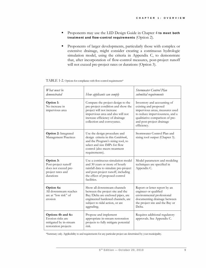
Compliance with Flow-Control Requirements As shown in Table 1-1, in addition to incorporating treatment controls, projects creating or replacing an acre or more of impervious area must also provide flow control so post-project runoff does not exceed estimated pre-project rates and durations. Projects subject to flow-control requirements have four options for demonstrating compliance. The options are summarized in Table 1-2. Detailed requirements are in Appendix C.
Depending on location and existing site conditions, a project proponent may wish to consider the feasibility of these options in the following order:
For projects on previously developed sites, it may be possible to show the project will not increase the existing quantity of impervious area and will not facilitate the efficiency of drainage collection and conveyance (Option 1).
Depending on project location, the project proponent may be able show all downstream channels between the project site and the Bay/Delta are enclosed pipes, are engineered hardened channels, are subject to tidal action, or are aggrading (Option 4a).
C H A P T E R 1 : O V E R V I E W
5th Edition — October 20, 2010 9
Proponents may use the LID Design Guide in Chapter 4 to meet both treatment and flow-control requirements (Option 2).
Proponents of larger developments, particularly those with complex or extensive drainage, might consider creating a continuous hydrologic simulation model, using the criteria in Appendix C, to demonstrate that, after incorporation of flow-control measures, post-project runoff will not exceed pre-project rates or durations (Option 3).
TABLE 1-2. Options for compliance with flow-control requirements*
What must be demonstrated How applicants can comply
Stormwater Control Plan submittal requirements
Option 1: No increase in impervious area
Compare the project design to the pre-project condition and show the project will not increase impervious area and also will not increase efficiency of drainage collection and conveyance.
Inventory and accounting of existing and proposed impervious areas, measures used to reduce imperviousness, and a qualitiative comparison of pre- and post-project drainage efficiency.
Option 2: Integrated Management Practices
Use the design procedure and design criteria in this Guidebook, and the Program’s sizing tool, to select and size IMPs for flow control (also meets treatment requirements).
Stormwater Control Plan and sizing tool output (Chapter 3).
Option 3: Post-project runoff does not exceed pre-project rates and durations
Use a continuous-simulation model and 30 years or more of hourly rainfall data to simulate pre-project and post-project runoff, including the effect of proposed control facilities.
Model parameters and modeling techniques are specified in Appendix C.
Option 4a: All downstream reaches are at “low risk” of erosion
Show all downstream channels between the project site and the Bay/Delta are enclosed pipes, are engineered hardened channels, are subject to tidal action, or are aggrading.
Report or letter report by an engineer or qualified environmental professional documenting drainage between the project site and the Bay or Delta.
Options 4b and 4c: Erosion risks are mitigated by in-stream restoration projects
Propose and implement appropriate in-stream restoration projects to fully mitigate potential risk.
Requires additional regulatory approvals. See Appendix C.
*Summary only. Applicability to and requirements for any particular project are determined by your municipality.
C O N T R A C O S T A C L E A N W A T E R P R O G R A M
10 5th Edition — October 20, 2010
Under Options 4b and 4c, proponents may propose and implement an appropriate in-stream restoration project to fully mitigate the potential risk of increased downstream erosion created by their proposed development.
Runoff treatment is required regardless of the flow-control compliance option chosen.
Alternative Compliance Options In lieu of incorporating facilities to treat runoff from impervious areas at the development project site, an applicant may propose a secondary project that will treat runoff from an equivalent amount of impervious area at another location within the same watershed.
To be considered, the secondary project must include construction, operation, and maintenance of facilities meeting the criteria in Chapter 4. Those facilities must treat runoff from an amount of impervious surface equivalent to, or greater than, the impervious surface that would be subject to requirements at the project location.
An applicant may propose to combine on-site and off-site facilities to add up to the equivalent amount of impervious area as would be required for only on-site treatment. An applicant may also propose to share in a larger project and be credited for a proportional amount of the impervious area for which runoff is treated by that project.
Consideration or acceptance of such proposals is at the discretion of the local municipality.
Experience has shown implementation of LID facilities, as described in Chapter 4, is feasible on nearly all development sites with sufficient advance planning.
References and Resources:
Appendix C—Flow Control CCCWP Policy for C.3 Compliance for Subdivisions CCCWP Web Page for Construction Activities CCCWP Hydrograph Modification Management Plan MRP Provision C.3.g. and Attachment C (Hydrograph Modification Management) MRP Provision C.3.e. (Alternative or In-Lieu Compliance)
S T O R M W A T E R C . 3 . C O M P L I A N C E
5th Edition — October 20, 2010 11
Concepts and Criteria Technical background and explanations of policies and design requirements
he Regional Water Board first issued a municipal stormwater NPDES permit to Contra Costa County, its cities and towns, and the Contra Costa Flood Control and Water Conservation District in 1993. The permit mandates a comprehensive program to prevent stormwater pollution.
That program now includes measures to prevent pollution from municipal facilities and operations, identification and elimination of illicit discharges to storm drains, business inspections, public outreach, construction site inspections, monitoring and studies of stream health, and control of runoff pollutants from new developments and redevelopments.
The Regional Water Board added Provision C.3 in 2003, and the permittees began implementing the provision in 2005. The Regional Water Board added hydrograph modification management (flow control) requirements in 2006.
In October 2009, the Regional Water Board included Contra Costa municipalities in its first Municipal Regional Permit (MRP). The MRP applies to 77 municipal Bay Area permittees and supersedes the countywide stormwater NPDES permits.
The MRP mandates a Low Impact Development (LID) approach similar to that developed by the CCCWP from 2003 through 2009. This chapter explains the technical background of the LID approach and how it was derived.
Water-Quality Regulations MRP Provision C.3 requires municipalities to condition development approvals with incorporation of specified stormwater controls. The municipalities’ annual report to the Regional Water Board includes a list of development projects approved during the year and the specific stormwater controls required for each project. In the annual report, the municipalities also document their program to verify stormwater treatment and flow-control facilities are being adequately
Chapter
2
T
C O N T R A C O S T A C L E A N W A T E R P R O G R A M
12 5th Edition — October 20, 2010
maintained. The municipalities—not the Regional Board or its staff—are charged with ensuring development projects comply with the C.3 requirements. (Regional Water Board staff sometimes reviews stormwater controls in connection with applications for Clean Water Act Section 401 water-quality certification, which is required for projects that involve work in streams, including dredging and filling.)
In a nutshell, MRP Provision C.3 requires that applicable new developments and redevelopments:
Design the site to minimize imperviousness, detain runoff, and infiltrate, reuse or evapotranspirate runoff where feasible
Cover or control sources of stormwater pollutants
Treat runoff prior to discharge from the site
Ensure runoff does not exceed pre-project peaks and durations
Maintain treatment and flow-control facilities
► MAXIMUM EXTENT PRACTICABLE
Clean Water Act Section 402(p)(3)(iii) sets the standard for control of stormwater pollutants as “maximum extent practicable,” but doesn’t define that term. As implemented, “maximum extent practicable” is ever-changing and varies with conditions.
Many stormwater controls, including LID, have proven to be practicable in most development projects. To achieve fair and effective implementation, criteria and guidance for those controls must be detailed and specific—while also offering the right amount of flexibility or exceptions for special cases. The MRP includes various standards, including hydrologic criteria, which have been found to provide “maximum extent practicable” control. CCCWP’s C.3 guidance is continuously improved and refined based on the experience of municipal planners and engineers, with input from land developers and development professionals.
► BEST MANAGEMENT PRACTICES
Clean Water Act Section 402(p) and USEPA regulations (40 CFR 122.26) specify a municipal program of “management practices” to control stormwater pollutants. Best Management Practice (BMP) refers to any kind of procedure or device designed to minimize the quantity of pollutants that enter the Municipal Separate Storm Sewer System (MS4).
To minimize confusion, this guidebook refers to “facilities,” “features,” “controls,” and Integrated Management Practices (IMPs) to be incorporated into development projects. All of these are BMPs.
C H A P T E R 2 : S T O R M W A T E R C O N C E P T S
5th Edition — October 20, 2010 13
Hydrology for NPDES Compliance ► IMPERVIOUSNESS
Schueler (1995) proposed imperviousness as a “unifying theme” for the efforts of planners, engineers, landscape architects, scientists, and local officials concerned with urban watershed protection. Schueler argued (1) that imperviousness is a useful indicator linking urban land development to the degradation of aquatic ecosystems, and (2) imperviousness can be quantified, managed, and controlled during land development.
Imperviousness has long been understood as the key variable in urban hydrology. Peak runoff flow and total runoff volume from small urban catchments is usually calculated as a function of the ratio of impervious area to total area (rational method). The ratio correlates to the composite runoff factor, usually designated “C”. Increased flows resulting from urban development tend to increase the frequency of small-scale flooding downstream.
Imperviousness links urban land development to degradation of aquatic ecosystems in two ways.
First, the combination of paved surfaces and piped runoff efficiently collects urban pollutants and transports them, in suspended or dissolved form, to surface waters. These pollutants may originate as airborne dust, be washed from the atmosphere during rains, or may be generated by automobiles and outdoor work activities.
Second, increased peak flows and runoff durations can cause erosion of stream banks and beds, transport of fine sediments, and disruption of aquatic habitat. Measures taken to control stream erosion, such as hardening banks with riprap or concrete, may permanently eliminate habitat. By reducing infiltration to groundwater, imperviousness may also reduce dry-weather stream flows.
Imperviousness has two major components: rooftops and transportation (including streets, highways, and parking areas). The transportation component is usually larger and is more likely to be directly connected to the storm drain system.
The effects of imperviousness can be mitigated by disconnecting impervious areas from the drainage system and by making drainage less efficient—that is, by encouraging detention and retention of runoff near the point where it is generated. Detention and retention reduce peak flows and volumes and allow pollutants to settle out or adhere to soils before they can be transported downstream.
C O N T R A C O S T A C L E A N W A T E R P R O G R A M
14 5th Edition — October 20, 2010
► SIZING REQUIREMENTS FOR STORMWATER TREATMENT FACILITIES
MRP permit criteria for sizing stormwater treatment facilities and flow-control facilities are based on simulation of runoff from a long-term (30-year or more) rainfall record. This is different from the “event-based” or “design storm” hydrology typically used to size drainage and flood-control facilities.
The CCCWP’s LID design guidance (Chapter 4) was crafted to ensure LID facilities comply with the NPDES permit’s hydraulic sizing requirements for stormwater treatment facilities and flow-control facilities, as well as meeting the LID mandate in MRP Provision C.3.c. The technical background follows.
Most runoff is produced by frequent storms of small or moderate intensity and duration. Treatment facilities are designed to treat smaller storms and the first flush of larger storms—approximately 80% of average annual runoff.
MRP Provision C.3.d. identifies two sets of criteria for sizing stormwater treatment facilities—volume-based and flow-based.
For volume-based treatment facilities, MRP Provision C.3.d. references two alternative methods, the WEF method and the California BMP method. As described in Chapter 4, local rainfall data and the California BMP method are used for sizing detention basins in Contra Costa County. Both the WEF and California
BMP methods are based on continuous simulation of runoff from a hypothetical one-acre area entering a basin designed to draw down in 48 hours. The simulation is iterated to find the unit basin size that detains about 80% of the total runoff during the simulation period. The unit basin storage size is expressed as a depth which varies from about 0.45" to 0.85" in Contra Costa County.
For flow-based facilities, the NPDES permit specifies the rational method be used to determine flow. The rational method uses the equation
Q = CiA, where
Q = flow
C = weighted runoff factor between 0 and 1
i = rainfall intensity
A = area
The permit identifies three alternatives for calculating rainfall intensity:
I C O N K E Y
Helpful Tip
Submittal Requirement
Terms to Look Up
References & Resources
C H A P T E R 2 : S T O R M W A T E R C O N C E P T S
5th Edition — October 20, 2010 15
1. the intensity-duration-frequency method, with a hydrograph corresponding to a 50-year storm,
2. the 85th percentile rainfall intensity times two, and
3. 0.2 inches per hour.
An analysis conducted for the CCCWP determined all three methods yielded similar results. The 0.2 inches per hour rainfall intensity is used for sizing flow-based treatment facilities in Contra Costa County. This intensity corresponds to storms producing approximately 0.6 inches precipitation.
The CCCWP used the 0.2 inches per hour criterion to develop a consistent countywide sizing factor for bioretention facilities when used for stormwater treatment only (i.e., not for flow control). The factor is based on a design maximum surface loading rate of 5 inches per hour (now mandated by MRP Provision C.3.c.i.(2)(b)(iv)). The sizing factor is the ratio of the design intensity of rainfall on tributary impervious surfaces (0.2 inches/hour) to the design percolation rate in the facility (5 inches/hour), or 0.04 (dimensionless).
► FLOW-CONTROL (HYDROGRAPH MODIFICATION MANAGEMENT)
MRP Provision C.3.g. specifies for applicable projects:
“Increases in runoff flow and volume shall be managed so that post-project runoff shall not exceed estimated post-project runoff peaks and durations, where such increased flow and/or volume is likely to cause increased potential for erosion of creek beds and banks, silt pollutant generation, or other adverse impacts on beneficial uses due to increased erosive force.”
Contra Costa applicants for development approvals may select among four options for compliance. See Table 1-2. The first three options allow an applicant to demonstrate—by showing there will be no net increase in impervious area, by using Integrated Management Practice designs and sizing factors developed by the CCCWP, or by constructing a site-specific hydrologic model—that runoff will not exceed pre-project rates and durations.*
* For sites that are already partially developed, see the Technical Memorandum, “Guidance on Flow Control For Development Projects on Sites that are Already Partially Developed,” on the CCCWP’s
Applicants may use the fourth option to demonstrate that, even though runoff will increase, it will not cause erosion or other significant effects on beneficial uses. This may be done by showing downstream channels are not susceptible to erosion (Option 4a) or that a
C.3 web pages.
C O N T R A C O S T A C L E A N W A T E R P R O G R A M
16 5th Edition — October 20, 2010
restoration project will mitigate any impacts from increased flows (Options 4b and 4c).
Details on compliance requirements are in Appendix C. Technical background is in the Hydrograph Modification Management Plan, which is available on the CCCWP’s website.
Selection of Stormwater Treatment Facilities The MRP mandates an LID approach similar to the approach developed by Contra Costa municipalities and incorporated in earlier editions of this Stormwater C.3 Guidebook.
► HARVESTING, USE, INFILTRATION, AND EVAPOTRANSPIRATION
MRP Provision C.3.c.i.(2)(b) requires applicable projects to treat 100% of the amount of runoff identified in Provision C.3.d. using LID facilities, which are defined as follows:
LID treatment measures are harvesting and re-use, infiltration, evapotranspiration, or biotreatment.
A properly engineered and maintained biotreatment system may be considered only if it is infeasible to implement harvesting and re-use, infiltration, or evapotranspiration at a project site.
Infeasibility to implement harvesting and re-use, infiltration, or evapotranspiration at a project site may result from conditions including the following:
Locations where seasonal high groundwater would be within 10 feet of the LID treatment measure.
Locations within 100 feet of a groundwater well used for drinking water.
Development sites where pollutant mobilization in the soil or groundwater is a documented concern.
Locations with potential geotechnical hazards.
Smart growth and infill or development sites where the density and nature of the project would create significant difficulty for compliance with the onsite volume retention requirement.
C H A P T E R 2 : S T O R M W A T E R C O N C E P T S
5th Edition — October 20, 2010 17
Locations with tight clay soils that significantly limit the infiltration of stormwater.
Here is how these requirements are implemented in Contra Costa municipalities:
The LID Design Guide directs the applicant to first consider incorporating into the proposed project design LID features that minimize runoff. These features include:
Minimized disturbance of natural drainage
Minimized amount of roofs and paving
Permeable pavements and green roofs
Dispersing runoff to landscape
Remaining runoff from impervious surfaces must be directed to LID facilities designed to the hydraulic sizing criteria in Provision C.3.d.
The LID Design Guide then directs the applicant to assess the feasibility of meeting the permit’s treatment and flow-control requirements—for each specific sub-drainage area within the site—by storing runoff for later use.
There are two options identified.
The first option is to store runoff for two days or less, which requires a consistent, reliable demand for a non-potable use other than irrigation. For this option, the applicant is directed to calculate the required storage and 48-hour drawdown rate for 80% capture. This calculation uses the methodology specified in CASQA Handbook and local rainfall data as specified in MRP Provision C.3.d.i.(1)(b). It is presumed storage of this quantity of runoff is feasible, and the applicant is directed to evaluate whether a reliable, accessible, implementable non-potable demand exists for this supply during the rainy season.
The second option is to accumulate runoff throughout the rainy season for use during the irrigation season. The required storage volume is calculated using the mean annual precipitation falling on the impervious surface times a factor of 0.6, which accounts for estimated losses to evaporation (less than 10%), the 80% capture of runoff, and runoff produced and used during the irrigation season (May – October). The applicant is directed to evaluate whether (1) there is sufficient landscape within or near the project to ensure demand for this quantity of water each year, and (2) whether annual storage of this quantity of water is feasible.
C O N T R A C O S T A C L E A N W A T E R P R O G R A M
18 5th Edition — October 20, 2010
For projects located at sites with Hydrologic Soil Group “A” or “B” soils, the LID Design Guide requires remaining runoff be routed to one of the following types of facilities:
Dry well
Bioretention
Cistern + Bioretention
Bioretention + Vault
All of these facilities are designed to infiltrate at least the flow of runoff specified in Provision C.3.d. when sized and configured for “treatment only” and a greater volume when sized and configured for “treatment and flow control.”
For projects located at sites with “tight clay soils that significantly limit the infiltration of stormwater” (Hydrologic Soil Group “C” and “D” soils), the LID Design Guide requires remaining runoff be routed to one of the following facilities:
Bioretention
Cistern + Bioretention
Bioretention + Vault
In these soil conditions, the amount of infiltration and evapotranspiration achieved by a bioretention facility is subject to unpredictable variation based on location-specific soil, slopes, and subsurface drainage patterns. Bioretention facilities are designed to facilitate infiltration and evapotranspiration to the extent feasible given conditions at the location.
Flow-through planters may be used where facilities are located on upper-story plazas, adjacent to building foundations, where mobilization of pollutants in soil or groundwater is a concern, and where potential geotechnical hazards are associated with infiltration. Flow-through planters facilitate evapotranspiration and, like bioretention facilities, reuse runoff to promote growth of plants within the facility.
Pending Actions MRP Provision C.3.c.iii.(1)
requires the municipal permitees to submit proposed feasibility
and infeasibility criteria for runoff storage/reuse and
infiltration to the Water Board by May 1, 2011.
C H A P T E R 2 : S T O R M W A T E R C O N C E P T S
5th Edition — October 20, 2010 19
► NON-LID TREATMENT FACILITIES
MRP Provision C.3.e.ii.(1) states:
When considered at the watershed scale, certain types of smart growth, high density and transit-oriented development can either reduce existing impervious surfaces, or create less “accessory” impervious areas and automobile-related pollutant impacts. Incentive LID treatment reduction credits approved by the Water Board may be applied to these types of Special Projects.
Through experience, Contra Costa municipalities have determined the LID facilities in Chapter 4 can be implemented on most “smart growth, high-density, and transit-oriented development,” and have decided LID facilities should be incorporated on those projects. Contra Costa municipalities have set an overall goal of incorporating LID treatment for runoff from at least 95% of impervious area created or replaced, and incorporating non-LID treatment for runoff from the remaining 5% of impervious area created or replaced.
Projects where LID may not always be feasible generally fall into one of the following two categories:
Portions of sites which are not being developed or redeveloped, but which must be retrofit to meet treatment requirements in accordance with the “50% rule.”
Sites smaller than one acre approved for lot-line to lot-line development or redevelopment as part of a municipality’s stated objective to preserve or enhance a pedestrian-oriented “smart-growth” type of urban design.
In these special situations, municipal staff may—based on evidence that 100% LID treatment is infeasible—allow non-LID treatment to be used to treat runoff from some or all impervious surfaces. The non-LID treatment must include media filtration.
Regional Water Board staff has found oil/water separators (“water quality inlets”) and storm drain inlet filters do not meet the “maximum extent practicable”
Pending Actions MRP Provision C.3.e.ii.(2)
requires the municipal permitees to submit types of projects
proposed for consideration of “LID treatment reduction
credits” to the Water Board by December 1, 2010.
C O N T R A C O S T A C L E A N W A T E R P R O G R A M
20 5th Edition — October 20, 2010
standard.* When used as a sole method of stormwater treatment, hydrodynamic separators, including vortex separators and continuous deflection separators (“CDS units”), do not meet the “maximum extent practicable” requirement, although they may be used in series with other facilities.†
Criteria for Infiltration Devices
MRP Provision C.3.d.iv. restricts the design and location of “infiltration devices” that, as designed, may bypass filtration through surface soils before reaching groundwater. These devices include dry wells, infiltration basins, and infiltration trenches, but do not include bioretention facilities or other facilities that treat runoff before allowing it to infiltrate.
Infiltration devices may not be used in areas of industrial or light industrial activity; areas subject to high vehicular traffic (25,000 or greater average daily traffic on main roadway or 15,000 or more average daily traffic on any intersecting roadway); automotive repair shops; car washes; fleet storage areas (bus, truck, etc.); nurseries, or other areas with pollutant sources that could pose a high threat to water quality, as determined by municipal staff.
The vertical distance from the base of any infiltration device to the seasonal high groundwater mark shall be at least 10 feet. Infiltration devices shall be located a minimum of 100 feet horizontally from any known water supply wells.
In addition, infiltration devices are not recommended where:
The infiltration device would receive drainage from areas where chemicals are used or stored, where vehicles or equipment are washed, or where refuse or wastes are handled.
Surface soils or groundwater are polluted.
The facility could receive sediment-laden runoff from disturbed areas or unstable slopes.
Increased soil moisture could affect the stability of slopes of foundations.
* “Use of Storm Drain Inlet Filters and Oil/Water Separators to Meet the Requirements of NPDES Municipal Stormwater Permits,” letter from Regional Water Board Executive Officer Bruce Wolfe to Bay Area Stormwater Management Agencies Association managers, August 5, 2004
† Policy on the Use of Hydrodynamic Separators to Achieve Compliance with NPDES Provision C.3, November 16, 2005

C H A P T E R 2 : S T O R M W A T E R C O N C E P T S
5th Edition — October 20, 2010 21
Soils are insufficiently permeable to allow the device to drain within 72 hours.
► MOST LID FEATURES AND FACILITIES ARE NOT INFILTRATION DEVICES
Self-treating and self-retaining areas, pervious pavements, bioretention facilities, and flow-through planters are not considered to be infiltration devices because they do not bypass filtration through surface soils before reaching groundwater.
Bioretention facilities work by percolating runoff through 18 inches or more of engineered soil. This removes most pollutants before the runoff is allowed to seep into native soils below or discharge through the outlet. Further pollutant removal typically occurs in the unsaturated (vadose) zone before moisture reaches groundwater. Self-treating and self-retaining areas allow removal of pollutants in surface soils before runoff mixes with groundwater.
Where there is concern about the effects of increased soil moisture on slopes or foundations, an impermeable barrier may be added so the facility is “flow through” and all treated runoff is underdrained away from the facility. See the design sheets for Bioretention Facilities and Flow-Through Planters in Chapter 4.
Environmental Benefit Perspective The diverse natural geography of Contra Costa County includes tidal and freshwater wetlands, alluvial plains, and mountain slopes. Average annual rainfall varies from 12.5 inches in Brentwood to 30 inches in Orinda.
The climate, soils, slope, and vegetation give each Contra Costa stream a characteristic structure of riffles, pools, terraces, floodplains, and wetlands. In relatively undisturbed stream reaches, this geomorphic structure supports trees and other riparian vegetation. Trees provide shade (cooling stream temperatures), create root wads and undercut banks (refuge for fish) and produce falling leaves and detritus (the bottom of a food web). Fish, frogs, and other animals have evolved to thrive in riparian habitats. Because Contra Costa habitats are diverse and complex, some species are specialized, have limited ranges, and may be rare.
Contra Costa’s landscape, like that of all the San Francisco Bay Area, has been repeatedly transformed since the Spanish arrived in the 1770s. Even before the area was developed, European grasses, weeds, and other plants replaced much of the native vegetation. Creek flows were diverted to irrigate farms, and wetlands were diked or filled for farmland.
Suburbs and former farm towns developed rapidly during and after the Second World War. In many places, to make flood-prone land suitable for development, creeks were channelized or confined within levees. Buildings, streets, and pavement now cover much of the land, and storm drains pipe runoff from urban
C O N T R A C O S T A C L E A N W A T E R P R O G R A M
22 5th Edition — October 20, 2010
neighborhoods directly into the creeks. Urbanization has changed the timing and intensity of stream flows and has set off a chain of unanticipated consequences. These consequences include more frequent flooding, destabilized stream banks, armoring of streambanks with riprap and concrete, loss of streamside trees and vegetation, and the destruction of stream habitat.
The remaining habitat, even where it has been disturbed and reduced to remnants, is an important refuge for various species. The U.S. and California have listed some of these species, including steelhead (Oncorhyncus mykiss), as endangered. Other species are listed as threatened, rare, or having other special status.
Once altered, natural streams and their ecosystems cannot be fully restored. However, it is possible to stop, and partially reverse, the trend of declining habitat and preserve and enhance some ecosystem values for the benefit of future generations.
This is an enormous, long-term effort. Managing runoff from a single development site may seem inconsequential, but by changing the way most sites are developed (and redeveloped), we may be able to preserve and enhance existing stream ecosystems in urban and urbanizing areas.
References and Resources
The Importance of Imperviousness (Tom Scheuler, 1995) Site Planning for Urban Stream Protection, available from the Center for Watershed Protection)
California Stormwater BMP Handbooks Urban Runoff Quality Management, Water Environment Federation and
American Society of Civil Engineers, 1998. ISBN 1-57278-039-8 ISBN 0-7844-0174-8. Policy on Selection of Stormwater Treatment Facilities for Maximum Extent Practicable Effectiveness in Compliance with
NPDES Provision C.3 (CCCWP, 2007) Use of Storm Drain Inlet Filters and Oil/Water Separators to Meet the Requirements of NPDES Municipal Stormwater
Permits,” letter from Regional Water Board Executive Officer Bruce Wolfe to Bay Area Stormwater Management Agencies Association managers, August 5, 2004
Stormwater Infiltration, Bruce K. Ferguson, 1994. ISBN 0-87371-987-5 Municipal Regional Permit Provisions C.3.c., C.3.d., C.3.e. RWQCB Water Quality Control Plan for the San Francisco Bay Basin (Basin Plan) RWQCB Water Quality Control Plan for the Central Valley Region (Basin Plan) Clean Water Act Section 402(p) 40 CFR 122.26(d)(2)(iv)(A)(2) – Stormwater Regulations for New Development Restoring Streams in Cities (Riley, 1998) Stream Restoration: Principles, Processes, and Practices
(Federal Interagency Stream Restoration Working Group, 1998, revised 2001) Contra Costa County Watershed Atlas (Contra Costa County, 2003
S T O R M W A T E R C . 3 . C O M P L I A N C E
5th Edition — October 20, 2010 23
Preparing Your Stormwater Control Plan Step-by-step assistance to document compliance.
our Stormwater Control Plan will demonstrate your project complies with all applicable requirements in the stormwater NPDES permit—to minimize imperviousness, retain or detain stormwater, slow runoff rates, incorporate required source controls, treat stormwater prior to discharge
from the site, control runoff rates and durations if required, and provide for operation and maintenance of treatment and flow-control facilities.
The Plan must be submitted with your application for discretionary approvals and must have sufficient detail to ensure the stormwater design, site plan, and landscaping plan are congruent.
A complete and thorough Stormwater Control Plan will facilitate quicker review and fewer cycles of review. Every Contra Costa municipality requires a Stormwater Control Plan for every applicable project.
Your Stormwater Control Plan will consist of a report and an exhibit.
Municipal staff will use the checklist on the following page to evaluate your Plan:
Chapter
3
Y I C O N K E Y
Helpful Tip
Submittal Requirement
Terms to Look Up
References & Resources

C O N T R A C O S T A C L E A N W A T E R P R O G R A M
24 5th Edition — October 20, 2010
STORMWATER CONTROL PLAN CHECKLIST
CONTENTS OF EXHIBIT
Show all of the following on drawings:
Existing natural hydrologic features (depressions, watercourses, relatively undisturbed areas) and significant natural resources. (Step 1 in the following step-by-step instructions)
Existing and proposed site drainage network and connections to drainage off-site. (Step 3)
Layout of buildings, pavement, and landscaped areas. (Step 3)
Impervious areas proposed (roof, plaza/sidewalk, and streets/parking) and area of each. (Step 3)
Entire site divided into separate Drainage Management Areas, with each DMA identified as self-treating, self-retaining (zero-discharge), draining to a self-retaining area, or draining to an IMP. Each DMA has one surface type (roof, paving, or landscape), is labeled, and square footage noted. (Step 3)
Locations and sizes of proposed treatment and flow-control facilities. (Step 3)
Potential pollutant source areas, including refuse areas, outdoor work and storage areas, etc. listed in Appendix D and corresponding required source controls. (Step 4)
CONTENTS OF REPORT
Include all of the following in a report:
Narrative analysis or description of site features and conditions that constrain, or provide opportunities for, stormwater control. Include soil types (including Hydrologic Soil Group), slopes, and depth to groundwater (Step 2)
Narrative description of site design characteristics that protect natural resources. (Step 3)
Narrative description and/or tabulation of site design characteristics, building features, and pavement selections that minimize imperviousness of the site. (Step 3)
Evaluation of the feasibility of storage and use, infiltration, and evapotranspiration (Step 3).
Tabulation of DMAs, including self-treating areas, self-retaining areas, areas draining to self-retaining areas, and areas tributary to Integrated Management Practices (IMPs), in the format shown in Chapter 4. Output from the IMP Sizing Calculator may be used. (Step 3)
Sketches and/or descriptions showing there is sufficient hydraulic head to route runoff into, through, and from each IMP to an approved discharge point. (Step 3)
A table of identified pollutant sources and for each source, the source control measure(s) used to reduce pollutants to the maximum extent practicable. See worksheet in Appendix D. (Step 4)
General maintenance requirements for infiltration, treatment, and flow-control facilities. (Step 5)
Means by which facility maintenance will be financed and implemented in perpetuity. (Step 5)
Statement accepting responsibility for interim operation & maintenance of facilities. (Step 5)
Identification of any conflicts with codes or requirements or other anticipated obstacles to implementing the Stormwater Control Plan. (Step 6)
Construction Plan C.3 Checklist. (Step 6)
Certification by a civil engineer, architect, and landscape architect. (Step 6)
Appendix: Compliance with flow-control requirements (if using an HMP compliance option other than Option 2, Integrated Management Practices).
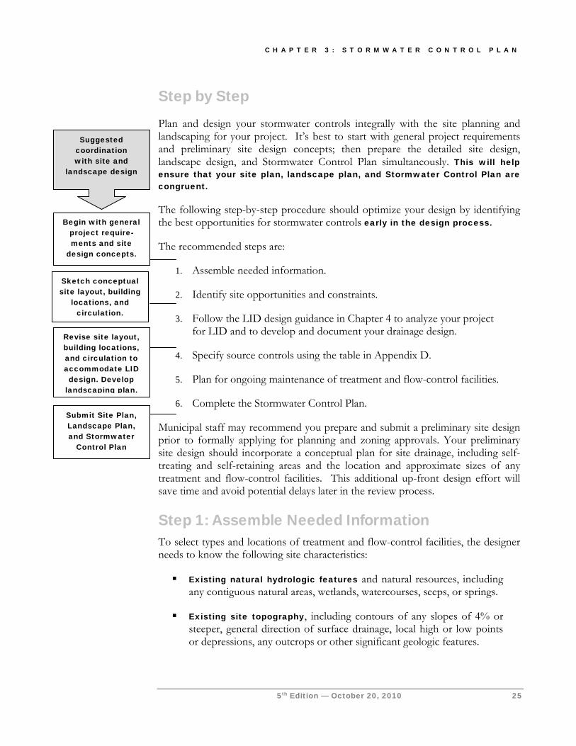
C H A P T E R 3 : S T O R M W A T E R C O N T R O L P L A N
5th Edition — October 20, 2010 25
Step by Step Plan and design your stormwater controls integrally with the site planning and landscaping for your project. It’s best to start with general project requirements and preliminary site design concepts; then prepare the detailed site design, landscape design, and Stormwater Control Plan simultaneously. This will help ensure that your site plan, landscape plan, and Stormwater Control Plan are congruent.
The following step-by-step procedure should optimize your design by identifying the best opportunities for stormwater controls early in the design process.
The recommended steps are:
1. Assemble needed information.
2. Identify site opportunities and constraints.
3. Follow the LID design guidance in Chapter 4 to analyze your project for LID and to develop and document your drainage design.
4. Specify source controls using the table in Appendix D.
5. Plan for ongoing maintenance of treatment and flow-control facilities.
6. Complete the Stormwater Control Plan.
Municipal staff may recommend you prepare and submit a preliminary site design prior to formally applying for planning and zoning approvals. Your preliminary site design should incorporate a conceptual plan for site drainage, including self-treating and self-retaining areas and the location and approximate sizes of any treatment and flow-control facilities. This additional up-front design effort will save time and avoid potential delays later in the review process.
Step 1: Assemble Needed Information To select types and locations of treatment and flow-control facilities, the designer needs to know the following site characteristics:
Existing natural hydrologic features and natural resources, including any contiguous natural areas, wetlands, watercourses, seeps, or springs.
Existing site topography, including contours of any slopes of 4% or steeper, general direction of surface drainage, local high or low points or depressions, any outcrops or other significant geologic features.
Begin with general project require-ments and site
design concepts.
Sketch conceptual site layout, building
locations, and circulation.
Submit Site Plan, Landscape Plan, and Stormwater
Control Plan
Suggested coordination with site and
landscape design
Revise site layout, building locations, and circulation to accommodate LID design. Develop
landscaping plan.
C O N T R A C O S T A C L E A N W A T E R P R O G R A M
26 5th Edition — October 20, 2010
Zoning, including requirements for setbacks and open space.
Soil types (including hydrologic soil groups) and depth to groundwater, which may determine whether infiltration is a feasible option for managing site runoff. Depending on site location and characteristics, and on the selection of treatment and flow-control facilities, site-specific information (e.g. from boring logs or geotechnical studies) may be required.
Existing site drainage. For undeveloped sites, this should be obtained by inspecting the site and examining topographic maps and survey data. For previously developed sites, site drainage and connection to the municipal storm drain system can be located from site inspection, municipal storm drain maps, and plans for previous development.
Existing vegetative cover and impervious areas, if any.
Step 2: Identify Constraints & Opportunities Review the information collected in Step 1. Identify the principal constraints on site design and selection of treatment and flow-control facilities as well as opportunities to reduce imperviousness and incorporate facilities into the site and landscape design. For example, constraints might include impermeable soils, high groundwater, groundwater pollution or contaminated soils, steep slopes, geotechnical instability, high-intensity land use, heavy pedestrian or vehicular traffic, utility locations, or safety concerns. Opportunities might include existing natural areas, low areas, oddly configured or otherwise unbuildable parcels, easements and landscape amenities including open space and buffers (which can double as locations for bioretention facilities), and differences in elevation (which can provide hydraulic head).
Prepare a brief narrative describing site opportunities and constraints. This narrative will help you as you proceed with LID design and explain your design decisions to others.
Step 3: Prepare and Document Your LID Design Use the Low Impact Development Design Guide (Chapter 4) to analyze your project for LID, design and document drainage, and specify preliminary design details for integrated management practices.
Chapter 4 includes calculation procedures and formats for presenting your calculations.
As shown in the checklist (page 24), your Exhibit must show:
C H A P T E R 3 : S T O R M W A T E R C O N T R O L P L A N
5th Edition — October 20, 2010 27
The entire site divided into separate Drainage Management Areas (DMAs), with each area identified as self-treating, self-retaining, draining to a self-retaining area, or draining to an IMP. Each area should be clearly marked with a unique identifier.
For each drainage area, the types of impervious area proposed, and the area of each.
Proposed locations and sizes of treatment and flow-control facilities. Each facility should be clearly marked with a unique identifier.
Your Stormwater Control Plan report must include:
An assessment of the feasibility of storing runoff and using it for irrigation or other non-potable use as a means of achieving criteria for treatment or treatment-and-flow-control. Use the equations and questions in Chapter 4.
Tabulation of proposed self-treating areas, self-retaining areas, areas draining to self-retaining areas, and areas draining to IMPs, and the corresponding IMPs identified on the Exhibit.
Calculations, in the format shown in Chapter 4, showing the minimum square footage required and proposed square footage for each IMP. If flow-control requirements apply, the required storage volume or volumes must also be shown.
Preliminary designs for each IMP. The design sheets and accompanying drawings in Chapter 4 may be used or adapted for this purpose.
Also include in your Stormwater Control Plan report:
A narrative overview of your design and how your design decisions optimize the site layout, use pervious surfaces, disperse runoff from impervious surfaces, and drain impervious surfaces to engineered IMPs. See Chapter 4.
A narrative briefly describing each DMA, its drainage, and where drainage will be directed.
A narrative briefly describing each IMP. Include any special characteristics or features distinct from the design sheets in Chapter 4.
Group and consolidate descriptions, or provide additional detail, as necessary to help the reviewer understand your drainage design.
C O N T R A C O S T A C L E A N W A T E R P R O G R A M
28 5th Edition — October 20, 2010
References and Resources
Chapter 4 Start at the Source (BASMAA, 1999). Your municipality’s General Plan Your municipality’s Zoning Ordinance and Development Codes Low Impact Development Manual (Prince George’s County, Maryland, 1999). Bioretention Manual (Prince George’s County, Maryland, rev. 2002) Low Impact Development Technical Guidance Manual for Puget Sound (Puget Sound Action Team, 2005) LID for Big Box Retailers (Low Impact Development Center, 2006)
Step 4. Specify Source Control BMPs Some everyday activities – such as trash recycling/disposal and washing vehicles and equipment – generate pollutants that tend to find their way into storm drains. These pollutants can be minimized by applying source control BMPs.
Source control BMPs include permanent, structural features that may be required in your project plans—such as roofs over and berms around trash and recycling areas—and operational BMPs, such as regular sweeping and “housekeeping,” that must be implemented by the site’s occupant or user. The maximum extent practicable standard typically requires both types of BMPs. In general, operational BMPs cannot be substituted for a feasible and effective permanent BMP.
Use the following procedure to specify source control BMPs for your site:
► IDENTIFY POLLUTANT SOURCES
Review the first column in the Pollutant Sources/Source Control Checklist (Appendix D
► NOTE LOCATIONS ON STORMWATER CONTROL PLAN EXHIBIT
). Check off the potential sources of pollutants that apply to your site.
Note the corresponding requirements listed in Column 2 of the Pollutant Sources/Source Control Checklist (Appendix D). Show the location of each pollutant source and each permanent source control BMP in your Stormwater Control Plan Exhibit.
► PREPARE A TABLE AND NARRATIVE
Check off the corresponding requirements listed in Column 3 in the Pollutant Sources/Source Control Checklist (Appendix D). Now, create a table using the format in Table 3-1. In the left column, list each potential source on your site (from Appendix E, Column 1). In the middle column, list the corresponding permanent, structural BMPs (from Columns 2 and 3, Appendix D) used to prevent pollutants from entering runoff. Accompany this table with a narrative that explains any special features, materials, or methods of construction that will be used to implement these permanent, structural BMPs.
C H A P T E R 3 : S T O R M W A T E R C O N T R O L P L A N
5th Edition — October 20, 2010 29
► IDENTIFY OPERATIONAL SOURCE CONTROL BMPS
To complete your table, refer once again to the Pollutant Sources/Source Control Checklist (Appendix D, Column 4). List in the right column of your table the operational BMPs that should be implemented as long as the anticipated activities continue at the site. The local stormwater ordinance requires that these BMPs be implemented; the same BMPs may also be required as a condition of a use permit or other revocable discretionary approval for use of the site.
References and Resources
Appendix D Municipal Regional Permit Provision C.3.c.
, Stormwater Pollutant Sources/Source Control Checklist
Start at the Source, Section 6.7: Details, Outdoor Work Areas Urban Runoff Quality Management (WEF/ASCE, 1998) Chapter 4: Source Controls
California Stormwater Industrial/Commercial Best Management Practice Handbook
Step 5: Stormwater Facility Maintenance As required by MRP Provision C.3.h, your local municipality will periodically verify that treatment and flow-control facilities on your site are maintained and continue to operate as designed.
To make this possible, your municipality will require that you include in your Stormwater Control Plan:
1. A means to finance and implement facility maintenance in perpetuity.
2. Acceptance of responsibility for maintenance from the time the facilities are constructed until responsibility for operation and maintenance is legally transferred. A warranty covering a period following construction may also be required.
3. An outline of general maintenance requirements for the treatment and flow-control facilities you have selected.
TABLE 3-1. Format for table of permanent and operational source control measures.
Potential source of runoff pollutants
Permanent source control BMPs
Operational source control BMPs
C O N T R A C O S T A C L E A N W A T E R P R O G R A M
30 5th Edition — October 20, 2010
Your local municipality will also require that you prepare and submit a detailed Stormwater Facilities Operation and Maintenance Plan that sets forth a maintenance schedule for each of the treatment and flow-control facilities built on your site. An agreement assigning responsibility for maintenance and providing for inspections and certification may also be required.
Details of these requirements, and instructions for preparing a Stormwater Facilities Operation and Maintenance Plan, are in Chapter 6.
References and Resources
Chapter
6 Model Stormwater Ordinance (CCCWP, 2005)
Operation, Maintenance, and Management of Stormwater Management Systems (Watershed Management Institute, 1997)
Step 6: Stormwater Control Plan Exhibit & Report Your Stormwater Control Plan should document the information gathered and decisions made in Steps 1-5. A clear, complete, well-organized Plan will make it possible to confirm your design meets the minimum requirements of the Municipal Regional Permit, the municipal stormwater pollution prevention ordinance, and this Guidebook.
► COORDINATION WITH SITE, ARCHITECTURAL, AND LANDSCAPING PLANS
Before completing your Stormwater Control Plan exhibit and report, ensure your stormwater control design is fully coordinated with the site plan, grading plan, and landscaping plan being proposed for the site.
Information submitted and presentations to design review committees, planning commissions, and other decision-making bodies must incorporate relevant aspects of the stormwater design. In particular, ensure:
Curb elevations, elevations, grade breaks, and other features of the drainage design are consistent with the delineation of DMAs.
The top edge (overflow) of each bioretention facility is level all around its perimeter—this is particularly important in parking lot medians.
The resulting grading and drainage design is consistent with the design for parking and circulation.
Bioretention facilities and other IMPs do not create conflicts with pedestrian access between parking and building entrances.
C H A P T E R 3 : S T O R M W A T E R C O N T R O L P L A N
5th Edition — October 20, 2010 31
Vaults and utility boxes will be accommodated outside bioretention facilities and will not be placed within bioretention facilities.
The visual impact of stormwater facilities, including planter boxes at building foundations and any terracing or retaining walls required for the stormwater control design, is shown in renderings and other architectural drawings.
Landscaping plans, including planting plans, show locations of bioretention facilities, and the plant requirements are consistent with the engineered soils and conditions in the bioretention facilities.
Renderings and representation of street views incorporate any stormwater facilities located in street-side buffers and setbacks.
Any potential conflicts with local development standards have been identified and resolved.
Review Chapter 5, IMP Construction, to anticipate additional requirements for construction of IMPs.
► CONSTRUCTION PLAN C.3 CHECKLIST
When you submit construction plans for City review and approval, the plan checker will compare that submittal with your Stormwater Control Plan. By creating a Construction Plan C.3 Checklist for your project, you will facilitate the plan checker’s comparison and speed review of your project.
Here’s how:
1. Create a table similar to Table 3-2. Number and list each measure or BMP you have specified in your Stormwater Control Plan in Columns 1 and 2 of the table. Leave Column 3 blank. Incorporate the table into your Stormwater Control Plan.
TABLE 3-2. Format for Construction Plan C.3 Checklist.
Stormwater Control Plan
Page # BMP Description See Plan Sheet #s
C O N T R A C O S T A C L E A N W A T E R P R O G R A M
32 5th Edition — October 20, 2010
2. When you submit construction plans, duplicate the table (by photocopy or electronically). Now fill in Column 3, identifying the plan sheets where the BMPs are shown. List all plan sheets on which the BMP appears. Submit the updated table with your construction plans.
Note that the updated table—or Construction Plan C.3 Checklist—is only a reference tool to facilitate comparison of the construction plans to your Stormwater Control Plan. Local municipal staff can advise you regarding the process required to propose changes to the approved Stormwater Control Plan.
See Chapter 5 for details of IMP construction to be included in construction plans.
► CERTIFICATION
Your local municipality may require that your Stormwater Control Plan be certified by an architect, landscape architect, or civil engineer. See Appendix A.
Your certification should state: “The selection, sizing, and preliminary design of stormwater treatment and other control measures in this plan meet the requirements of Regional Water Quality Control Board Order R2-2009-0074 and subsequent amendments.”
► STORMWATER CONTROL PLAN REPORT SAMPLE OUTLINE AND CONTENTS
I. Project Setting
A. Project Name, Location, Description
B. Existing site features and conditions
C. Opportunities and constraints for stormwater control
II. Low Impact Development Design Strategies
A. Optimization of site layout
(1) Limitation of development envelope
(2) Preservation of natural drainage features
(3) Setbacks from creeks, wetlands, and riparian habitats
(4) Minimization of imperviousness
(5) Using drainage as a design element
C H A P T E R 3 : S T O R M W A T E R C O N T R O L P L A N
5th Edition — October 20, 2010 33
B. Use of permeable pavements
C. Dispersal of runoff to pervious areas
D. Assessment of the feasibility of short-term and seasonal storage and reuse to meet treatment and flow-control requirements.
(1) Identification of impervious areas where runoff might be feasibly captured and stored.
(2) Calculation of minimum required storage and use rates for non-irrigation and irrigation uses for each such area.
(3) Storage for non-irrigation uses –Is there within the project site a reliable, accessible, implementable on-site non-potable demand to fully and reliably use the calculated supply during the rainy season?
(4) Storage for irrigation uses – Is there sufficient landscape within or near the project to ensure demand to the calculated quantity of water each year, and if so, is annual storage of this quantity of water feasible?
E. Use of Integrated Management Practices
III. Documentation of Drainage Design
A. Drainage Management Areas
(1) Tabulation
(2) Descriptions
B. Integrated Management Practices
(1) Tabulation and Sizing Calculations
(2) Descriptions
IV. Source Control Measures
A. Description of site activities and potential sources of pollutants
B. Table showing sources, permanent source controls, and operational source controls
V. Facility Maintenance Requirements
C O N T R A C O S T A C L E A N W A T E R P R O G R A M
34 5th Edition — October 20, 2010
A. Ownership and responsibility for maintenance in perpetuity.
(1) Commitment to execute any necessary agreements and/or annex into a fee mechanism, per local requirements.
(2) Statement accepting responsibility for operation and maintenance of facilities until that responsibility is formally transferred.
B. Summary of maintenance requirements for each stormwater facility.
VI. Construction Plan C.3 Checklist
VII. Certifications
Attachment: Stormwater Control Plan Exhibit
Appendix: Compliance with Flow-Control (Hydrograph Modification Management) requirements (if IMPs are not used).
► STORMWATER CONTROL PLAN TEMPLATE
A template with the above format and headings is available on the CCCWP website.
► EXAMPLE STORMWATER CONTROL PLANS
Example Stormwater Control Plans can be accessed via the CCCWP’s website. Because of the pace at which the Regional Water Board has issued new requirements, some of these plans may have been prepared under requirements that have now been superseded. Your Stormwater Control Plan will reflect the unique character of your own project and should meet the requirements identified in this Guidebook. Municipal staff can assist you to determine how specific requirements apply to your project.
S T O R M W A T E R C . 3 . C O M P L I A N C E
5th Edition — October 20, 2010 35
Low Impact Development Design Guide Guidance for designing and documenting your LID site drainage, stormwater treatment facilities, and flow-control facilities, including feasibility of storage for later use
our Stormwater Control Plan—to be submitted with your application for planning and zoning approvals (entitlements)—must show how your project will comply with the applicable Low Impact Development, stormwater treatment, and flow-control (hydrograph modification
management) standards in the Municipal Regional Permit (MRP).
This will require careful documentation of:
Pervious and impervious areas in the planned project.
Drainage from each of these areas.
Locations, sizes, and types of proposed LID, stormwater treatment, and flow-control facilities.
Your Stormwater Control Plan must include calculations showing the site drainage and proposed treatment and flow-control facilities meet the criteria in this Guidebook.
This Low Impact Development Design Guide will help you:
Analyze your project and identify and select options for meeting LID requirements and runoff treatment requirements—and flow-control requirements, if they apply.
Chapter
4
Y
C O N T R A C O S T A C L E A N W A T E R P R O G R A M
36 5th Edition — October 20, 2010
Design and document drainage for the whole site and document how that design meets this Guidebook’s stormwater treatment and flow-control criteria.
Specify preliminary design details and integrate your LID drainage design with your paving and landscaping design.
For most projects, you will need to iterate these three steps to converge on a workable design that complements site conditions and project objectives. Non-LID facilities are discussed in the final section of this chapter.
Before beginning your LID design, determine whether flow-control requirements apply to your site. See Table 1.1 in Chapter 1. If flow-control requirements apply, review Appendix C to understand your options for meeting those requirements. The calculation procedures in this Design Guide enable you to comply with flow-control requirements using “Option 2” in Appendix
C. If flow-control requirements do not apply, or if you are using another option to meet flow-control requirements, then you may use the treatment-only factors to size your facilities.
Analyze Your Project for LID Conceptually, there are five LID strategies for managing runoff from buildings and paving:
1. Optimize the site layout by preserving natural drainage features and designing buildings and circulation to minimize the amount of roofs and paving.
2. Use pervious surfaces such as turf, gravel, or pervious pavement—or use surfaces that retain rainfall, such as “green roofs.”
3. Disperse runoff from impervious surfaces on to adjacent pervious surfaces (e.g., direct a roof downspout to disperse runoff onto a lawn).
4. Store runoff and use it later for irrigation or other non-potable use.
5. Drain impervious surfaces to engineered Integrated Management Practices (IMPs), such as bioretention facilities, flow-through planters, or dry wells. IMPs evapotranspirate some runoff, infiltrate
I C O N K E Y
Helpful Tip
Submittal Requirement
Terms to Look Up
References & Resources
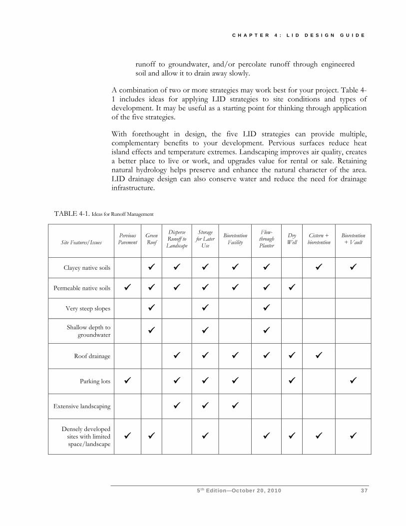
C H A P T E R 4 : L I D D E S I G N G U I D E
5th Edition—October 20, 2010 37
runoff to groundwater, and/or percolate runoff through engineered soil and allow it to drain away slowly.
A combination of two or more strategies may work best for your project. Table 4-1 includes ideas for applying LID strategies to site conditions and types of development. It may be useful as a starting point for thinking through application of the five strategies.
With forethought in design, the five LID strategies can provide multiple, complementary benefits to your development. Pervious surfaces reduce heat island effects and temperature extremes. Landscaping improves air quality, creates a better place to live or work, and upgrades value for rental or sale. Retaining natural hydrology helps preserve and enhance the natural character of the area. LID drainage design can also conserve water and reduce the need for drainage infrastructure.
TABLE 4-1. Ideas for Runoff Management
Site Features/Issues Pervious Pavement
Green Roof
Disperse Runoff to Landscape
Storage for Later
Use
Bioretention Facility
Flow-through Planter
Dry Well
Cistern + bioretention
Bioretention + Vault
Clayey native soils
Permeable native soils
Very steep slopes
Shallow depth to groundwater
Roof drainage
Parking lots
Extensive landscaping
Densely developed sites with limited space/landscape
C O N T R A C O S T A C L E A N W A T E R P R O G R A M
38 5th Edition — October 20, 2010
► OPTIMIZE THE SITE LAYOUT
To minimize stormwater-related impacts, apply the following design principles to the layout of newly developed and redeveloped sites:
Define the development envelope and protected areas, identifying areas that are most suitable for development and areas that should be left undisturbed.
Set back development from creeks, wetlands, and riparian habitats.
Preserve significant trees.
Where possible, conform the site layout along natural landforms, avoid excessive grading and disturbance of vegetation and soils, and replicate the site’s natural drainage patterns.
Concentrate development on portions of the site with less permeable soils, and preserve areas that can promote infiltration.
For all types of development, limit overall coverage of paving and roofs. This can be accomplished by designing compact, taller structures, narrower and shorter streets and sidewalks, smaller parking lots (fewer stalls, smaller stalls, and more efficient lanes), and indoor or underground parking. Examine site layout and circulation patterns and identify areas where landscaping can be substituted for pavement.
Detain and retain runoff throughout the site. On flatter sites, it typically works best to intersperse landscaped areas and IMPs among the buildings and paving. On hillside sites, drainage from upper areas may be collected in conventional catch basins and piped to landscaped areas and IMPs in lower areas. Or use low retaining walls to create terraces that can accommodate IMPs. Wherever possible, direct drainage from landscaped slopes offsite and not to IMPs.
Use drainage as a design element. Use depressed landscape areas, vegetated buffers, and bioretention areas as amenities and focal points within the site and landscape design. Bioretention areas can be almost any shape and should be located at low points.
► USE PERVIOUS SURFACES
Consider a green roof. Green roofs are growing (in popularity), and many have been built in the Bay Area in the last few years. Benefits include longer roof life, lower heating and cooling costs, and better sound insulation, in addition to air quality and water quality benefits.
Coordination
Chapter One includes a presentation of how review of your project’s site design
and landscape design is coordinated with review for compliance with Provision
C.3.
C H A P T E R 4 : L I D D E S I G N G U I D E
5th Edition—October 20, 2010 39
However, initial costs are higher than for conventional roofs, and green roofs may add to the complexity of permitting, financing, and insuring new buildings. For C.3 compliance purposes, green roofs are considered not to produce increased runoff or runoff pollutants (i.e., any runoff from a green roof requires no further treatment or detention).
Green roof designs with growing media 4 inches or deeper are encouraged but not required. Where possible, drainage from green roofs should be routed to landscaping rather than being tied directly into storm drains. This is because drain water may be high in organics due to extended contact with soils and plant roots.
Consider permeable pavements and surface treatments. Inventory paved areas on your preliminary site plan. Identify where permeable pavements, such as crushed aggregate, turf block, unit pavers, pervious concrete, or pervious asphalt could be substituted for impervious concrete or asphalt paving.
► DISPERSE RUNOFF TO ADJACENT PERVIOUS AREAS
Look for opportunities to direct runoff from impervious areas to adjacent landscaping. The design, including slopes and soils, must reflect a reasonable expectation that an inch of rainfall will soak into the soil and produce no runoff. For example, a lawn or garden depressed 3-4" below surrounding walkways or driveways provides a simple but functional landscape design element.
For sites subject to stormwater treatment requirements only, a 2:1 maximum ratio of impervious to pervious area is acceptable. If flow-control requirements apply, the impervious-to-pervious ratio must be limited to 1:1. Be sure soils will drain adequately.
Under some circumstances, it may be allowable to direct runoff from impervious areas to pervious pavement (for example, from roof downspouts to a parking lot paved with crushed aggregate or turf block). The pore volume of pavement and base course must be enough to retain an inch of rainfall, including runoff from the tributary area. The slopes and soils must be compatible with infiltrating that volume without producing runoff. This solution is most practical on flat sites with permeable soils.
► STORE RUNOFF FOR LATER USE
Use the following instructions and equations for a preliminary screening of the potential for storing runoff for later use on the site. As noted in Chapter 3, this determination of feasibility must be included in your Stormwater Control Plan.
Pending Actions MRP Provision C.3.c.i.(2)(b)(vii) requires the municipal permitees to submit proposed minimum specifications for green roofs
to the Water Board by December 1, 2010.
C O N T R A C O S T A C L E A N W A T E R P R O G R A M
40 5th Edition — October 20, 2010
First, identify all specific impervious areas (for example, a roof or portion of a roof) from which runoff might be feasibly captured and stored. Consider direction
of drainage and potential locations for runoff storage. Calculate the square footage of each area.
Then use the isohyetal diagram (County Public Works Drawing B-166) to estimate the Mean Annual Precipitation (MAP) at the project location.
Apply the following analysis for each specific impervious area identified. You will need to identify the Hydrologic Soil Group (A, B, C, or D) of the native soil underlying each specific impervious area.
Storing for a later use other than irrigation. If treatment-only requirements apply to your project (Table 1-1), use the following regression equation to estimate the storage volume for 80% capture:
Required volume (ft3) = Impervious area (ft2) × (0.0032 × MAP (in) + 0.0058) (Eq 4-1)
This volume must be used (i.e., storage must be fully drained) each 48 hours.
If flow-control requirements also apply, use Equation 4-5, p. 51, to calculate the required storage volume. Referring to Table 4-8, use the factor for the upstream volume V of a “cistern + bioretention” facility. Then use the appropriate equation for the site soil group (Equation 4-17, 4-12, 4-10, or 4-11 from Table 4-9 on p. 51) to calculate the required use rate.
Given the calculated use rate, answer the following question and include the answer in your Stormwater Control Plan:
Is there within or near the project site a reliable, accessible, implementable on-site non-potable demand to fully use this supply during the rainy season?
Consider opportunities to use stored runoff for:
Toilet flushing.
Industrial use.
Washing.
Other uses.
Pending Actions MRP Provision C.3.c.iii.(1)
requires the municipal permittees to submit proposed
feasibility and infeasibility criteria for runoff storage/reuse
and infiltration to the Water Board by May 1, 2011.
C H A P T E R 4 : L I D D E S I G N G U I D E
5th Edition—October 20, 2010 41
Storing for irrigation use. To be sure of diverting 80% of runoff for irrigation, it is necessary to store runoff during periods when there is little to no irrigation demand (approximately November through April) so that it may be used during the dry season. If treatment-only requirements apply, use the following equation to estimate the required storage:
Required volume (ft3) = Impervious area (ft2) × MAP (in)/12 × 0.6) (Eq 4-2)
Answer the following questions and include the answers in your Stormwater Control Plan: (1) Is there sufficient landscape within or near the project to ensure demand for this quantity of water each year? (2) If yes, is annual storage of this quantity of water feasible?
If flow-control requirements also apply, seasonal storage is not likely to be a feasible solution and need not be evaluated. Flow-control facilities are designed to store and release runoff flows which occur more rarely than once per year, and the facilities must be drained between storms.
If short-term or seasonal use of runoff from a specific impervious area is feasible, identify that area as a self-retaining drainage management area (DMA), as described on page 45.
Storage of a smaller volume of runoff for later use. Runoff storage that is less than the minimum calculated by Equations 4-1 and 4-2 is encouraged for water conservation. However, facilities for treatment and flow control must be sized independently of and in addition to storage for later use.
References and Resources
Municipal Handbook, Rainwater Harvesting Policies (USEPA, 2008) Green Roofs for Stormwater Runoff Control (USEPA, 2009a) Porous Pavements (Ferguson, 2005) Municipal Regional Permit Provision C.3.c.
► DIRECT RUNOFF TO INTEGRATED MANAGEMENT PRACTICES
The CCCWP has developed design criteria for the following IMPs:
Bioretention facilities, which can be configured as swales, free-form areas, or planters to integrate with your landscape design.
Flow-through planters, which can be used near building foundations and other locations where infiltration to native soils is not desired.
C O N T R A C O S T A C L E A N W A T E R P R O G R A M
42 5th Edition — October 20, 2010
Cistern + bioretention facilities, which use an upstream storage volume and metered flow to reduce the required square footage of a bioretention facility or flow-through planter.
Bioretention + vault facilities, which capture a volume downstream of bioretention and meter outflows.
Dry wells and other infiltration facilities, which can be used only where soils are permeable. See restrictions on page 20.
See the design sheets at the end of this chapter.
Finding the right location for treatment and flow-control facilities on your site involves a careful and creative integration of several factors:
To make the most efficient use of the site and to maximize aesthetic value, integrate IMPs with site landscaping. Many local zoning codes may require landscape setbacks or buffers, or may specify that a minimum portion of the site be landscaped. It may be possible to locate some or all of your site’s treatment and flow-control facilities within this same area, or within utility easements or other non-buildable areas.
Planter boxes and bioretention facilities must be level or nearly level all the way around. Linear bioretention facilities (swales) may be gently sloped end to end, but opposite sides must be at the same elevation. Facilities on steeper slopes must be terraced or provided with check dams.
For effective, low-maintenance operation, locate facilities so drainage into and out of the device is by gravity flow. Pumped systems are feasible, but are expensive, require more maintenance, are prone to untimely failure, and can cause mosquito control problems. Most IMPs require 3 feet or more of head.
Bioretention facilities and other IMPs require excavations three or more feet deep, which can conflict with underground utilities.
If the property is being subdivided now or in the future, the facility should be in a common, accessible area. In particular, avoid locating facilities on private residential lots. Even if the facility will serve only one site owner or operator, make sure the facility is located for ready access by inspectors from the local municipality and the Contra Costa Mosquito and Vector Control District.
The facility must be accessible to equipment needed for its maintenance. Access requirements for maintenance will vary with
C H A P T E R 4 : L I D D E S I G N G U I D E
5th Edition—October 20, 2010 43
the type of facility selected. Bioretention facilities will typically need access for the same types of equipment used for landscape maintenance.
To complete your analysis, include in your Stormwater Control Plan a brief narrative documenting the site layout and site design decisions you made. This will provide background and context for how your design meets the quantitative LID design criteria.
Develop and Document Your Drainage Design The CCCWP’s design documentation procedure begins with careful delineation of pervious areas and impervious areas (including roofs) throughout the site. The procedure accounts for how runoff from each delineated area is managed. For areas draining to IMPs, the procedure ensures each IMP is appropriately sized.
The procedure results in a space-efficient, cost-efficient LID design for meeting C.3 requirements on most residential and commercial/industrial developments. The procedure arranges documentation of drainage design and IMP sizing in a consistent format for presentation and review.
This procedure is intended to facilitate, not substitute for, creative interplay among site design, landscape design, and drainage design. Several iterations may be needed to optimize your drainage design as well as aesthetics, circulation, and use of available area for your site.
You should be able to complete the needed calculations using only the project’s site development plan, hydrologic soil group (A, B, C, or D) and mean annual precipitation. Mean annual precipitation at locations in Contra Costa County can be determined using isohyetal maps accessible from the CCCWP’s C.3 web page.
The CCCWP has created an IMP Sizing Calculator to facilitate the iterative calculations needed to create an optimal site design. The calculator is a stand-alone application and is available, along with instructions for its use, on the CCCWP’s C.3 web pages. In addition to performing calculations, the IMP Sizing Calculator formats calculation results into a summary report. The summary report can be attached to your Stormwater Control Plan submittal.
Should you decide to use the calculator, be sure to read through the following instructions, as they include key information you will need for design.
The following formulas and procedures can be used without the sizing calculator to complete calculations and prepare a report suitable for submittal with your Stormwater Control Plan. The same formulas and procedures should be used to check and verify calculations made with the IMP Sizing Calculator.
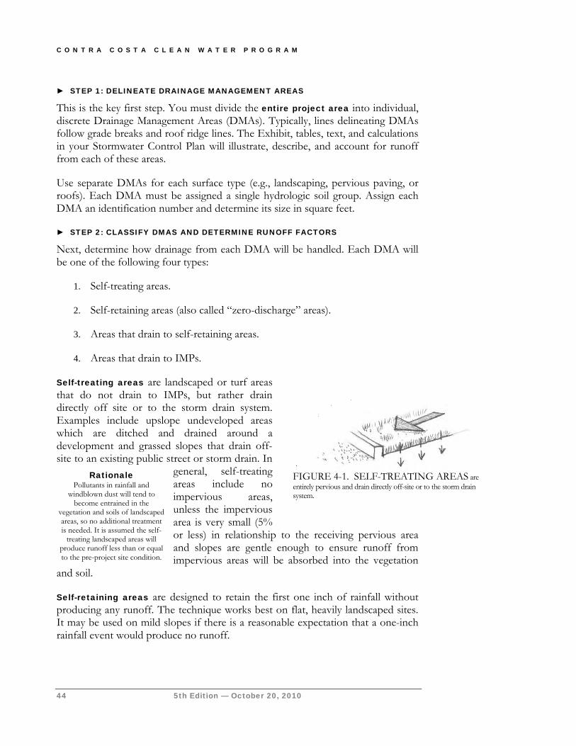
C O N T R A C O S T A C L E A N W A T E R P R O G R A M
44 5th Edition — October 20, 2010
► STEP 1: DELINEATE DRAINAGE MANAGEMENT AREAS
This is the key first step. You must divide the entire project area into individual, discrete Drainage Management Areas (DMAs). Typically, lines delineating DMAs follow grade breaks and roof ridge lines. The Exhibit, tables, text, and calculations in your Stormwater Control Plan will illustrate, describe, and account for runoff from each of these areas.
Use separate DMAs for each surface type (e.g., landscaping, pervious paving, or roofs). Each DMA must be assigned a single hydrologic soil group. Assign each DMA an identification number and determine its size in square feet.
► STEP 2: CLASSIFY DMAS AND DETERMINE RUNOFF FACTORS
Next, determine how drainage from each DMA will be handled. Each DMA will be one of the following four types:
1. Self-treating areas.
2. Self-retaining areas (also called “zero-discharge” areas).
3. Areas that drain to self-retaining areas.
4. Areas that drain to IMPs.
Self-treating areas are landscaped or turf areas that do not drain to IMPs, but rather drain directly off site or to the storm drain system. Examples include upslope undeveloped areas which are ditched and drained around a development and grassed slopes that drain off-site to an existing public street or storm drain. In
general, self-treating areas include no impervious areas, unless the impervious area is very small (5% or less) in relationship to the receiving pervious area and slopes are gentle enough to ensure runoff from impervious areas will be absorbed into the vegetation
and soil.
Self-retaining areas are designed to retain the first one inch of rainfall without producing any runoff. The technique works best on flat, heavily landscaped sites. It may be used on mild slopes if there is a reasonable expectation that a one-inch rainfall event would produce no runoff.
Rationale Pollutants in rainfall and
windblown dust will tend to become entrained in the
vegetation and soils of landscaped areas, so no additional treatment is needed. It is assumed the self-
treating landscaped areas will produce runoff less than or equal to the pre-project site condition.
FIGURE 4-1. SELF-TREATING AREAS are entirely pervious and drain directly off-site or to the storm drain system.
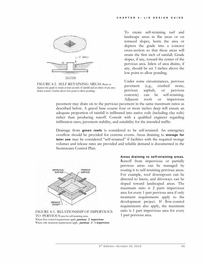
C H A P T E R 4 : L I D D E S I G N G U I D E
5th Edition—October 20, 2010 45
To create self-retaining turf and landscape areas in flat areas or on terraced slopes, berm the area or depress the grade into a concave cross-section so that these areas will retain the first inch of rainfall. Grade slopes, if any, toward the center of the pervious area. Inlets of area drains, if any, should be set 3 inches above the low point to allow ponding.
Under some circumstances, pervious pavement (e.g., crushed stone, pervious asphalt, or pervious concrete) can be self-retaining. Adjacent roofs or impervious
pavement may drain on to the pervious pavement in the same maximum ratios as described below. A gravel base course four or more inches deep will ensure an adequate proportion of rainfall is infiltrated into native soils (including clay soils) rather than producing runoff. Consult with a qualified engineer regarding infiltration rates, pavement stability, and suitability for the intended traffic.
Drainage from green roofs is considered to be self-retained. An emergency overflow should be provided for extreme events. Areas draining to storage for later use may be considered “self-retained” if facilities with the required storage volumes and release rates are provided and reliable demand is documented in the Stormwater Control Plan.
Areas draining to self-retaining areas. Runoff from impervious or partially pervious areas can be managed by routing it to self-retaining pervious areas. For example, roof downspouts can be directed to lawns, and driveways can be sloped toward landscaped areas. The maximum ratio is 2 parts impervious area for every 1 part pervious area if only treatment requirements apply to the development project. If flow-control requirements also apply, the maximum ratio is 1 part impervious area for every 1 part pervious area.
FIGURE 4-3. RELATIONSHIP OF IMPERVIOUS TO PERVIOUS area for self-retaining areas. Where flow-control requirements apply: pervious ≥ impervious Where only treatment requirements apply : pervious ≥ ½ impervious
FIGURE 4-2. SELF-RETAINING AREAS. Berm or depress the grade to retain at least an inch of rainfall and set inlets of any area drains at least 3 inches above low point to allow ponding.
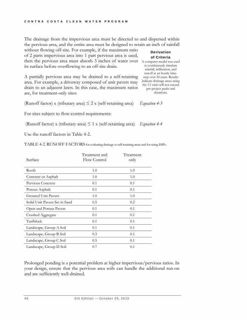
C O N T R A C O S T A C L E A N W A T E R P R O G R A M
46 5th Edition — October 20, 2010
The drainage from the impervious area must be directed to and dispersed within the pervious area, and the entire area must be designed to retain an inch of rainfall without flowing off-site. For example, if the maximum ratio of 2 parts impervious area into 1 part pervious area is used, then the pervious area must absorb 3 inches of water over its surface before overflowing to an off-site drain.
A partially pervious area may be drained to a self-retaining area. For example, a driveway composed of unit pavers may drain to an adjacent lawn. In this case, the maximum ratios are, for treatment-only sites:
(Runoff factor) x (tributary area) ≤ 2 x (self-retaining area) Equation 4-3
For sites subject to flow-control requirements:
(Runoff factor) x (tributary area) ≤ 1 x (self-retaining area) Equation 4-4
Use the runoff factors in Table 4-2.
TABLE 4-2. RUNOFF FACTORS for evaluating drainage to self-retaining areas and for sizing IMPs.
Surface Treatment and Flow Control
Treatment only
Roofs 1.0 1.0
Concrete or Asphalt 1.0 1.0
Pervious Concrete 0.1 0.1
Porous Asphalt 0.1 0.1
Grouted Unit Pavers 1.0 1.0
Solid Unit Pavers Set in Sand 0.5 0.2
Open and Porous Pavers 0.1 0.1
Crushed Aggregate 0.1 0.1
Turfblock 0.1 0.1
Landscape, Group A Soil 0.1 0.1
Landscape, Group B Soil 0.3 0.1
Landscape, Group C Soil 0.5 0.1
Landscape, Group D Soil 0.7 0.1
Prolonged ponding is a potential problem at higher impervious/pervious ratios. In your design, ensure that the pervious area soils can handle the additional run-on and are sufficiently well-drained.
Derivation of Criteria
A computer model was used to continuously simulate rainfall, infiltration, and
runoff at an hourly time-step over 30 years. Results
indicate drainage areas using the 1:1 ratio will not exceed
pre-project peaks and durations.
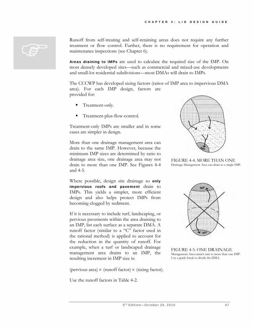
C H A P T E R 4 : L I D D E S I G N G U I D E
5th Edition—October 20, 2010 47
Runoff from self-treating and self-retaining areas does not require any further treatment or flow control. Further, there is no requirement for operation and maintenance inspections (see Chapter 6).
Areas draining to IMPs are used to calculate the required size of the IMP. On most densely developed sites—such as commercial and mixed-use developments and small-lot residential subdivisions—most DMAs will drain to IMPs.
The CCCWP has developed sizing factors (ratios of IMP area to impervious DMA area). For each IMP design, factors are provided for:
Treatment-only.
Treatment-plus-flow-control.
Treatment-only IMPs are smaller and in some cases are simpler in design.
More than one drainage management area can drain to the same IMP. However, because the minimum IMP sizes are determined by ratio to drainage area size, one drainage area may not drain to more than one IMP. See Figures 4-4 and 4-5.
Where possible, design site drainage so only impervious roofs and pavement drain to IMPs. This yields a simpler, more efficient design and also helps protect IMPs from becoming clogged by sediment.
If it is necessary to include turf, landscaping, or pervious pavements within the area draining to an IMP, list each surface as a separate DMA. A runoff factor (similar to a “C” factor used in the rational method) is applied to account for the reduction in the quantity of runoff. For example, when a turf or landscaped drainage management area drains to an IMP, the resulting increment in IMP size is:
(pervious area) × (runoff factor) × (sizing factor).
Use the runoff factors in Table 4-2.
FIGURE 4-5. ONE DRAINAGE Management Area cannot rain to more than one IMP. Use a grade break to divide the DMA.
FIGURE 4-4. MORE THAN ONE Drainage Management Area can drain to a single IMP.

C O N T R A C O S T A C L E A N W A T E R P R O G R A M
48 5th Edition — October 20, 2010
► STEP 3: TABULATE DRAINAGE MANAGEMENT AREAS
Tabulate self-treating areas in the format shown in Table 4-3.
Tabulate self-retaining areas in the format shown in Table 4-4.
Tabulate areas draining to self-retaining areas in the format shown in Table 4-5. Check to be sure the total amount of (square feet of tributary area × runoff factor) for all DMAs draining to a receiving self-retaining area is no greater than a 1:1 ratio to the square footage of the receiving self-retaining area itself. A 2:1 ratio may be used on sites not subject to flow-control requirements.
Compile a list of DMAs draining to IMPs. Proceed to Step 4 to check the sizing of the IMPs.
TABLE 4-3. FORMAT FOR TABULATING Self-Treating Areas
DMA Name
Area (square feet)
TABLE 4-4. FORMAT FOR TABULATING Self-Retaining Areas
TABLE 4-5. FORMAT FOR TABULATING Areas Draining to Self-Retaining Areas
DMA Name
Area (square feet)
DMA Name
Area
(square feet)
Post-project surface type
Runoff factor
Product (Area x runoff
factor)[A]
Receiving
self- retaining DMA
Receiving self- retaining
DMA Area (square feet)
[B]
Ratio [A]/[B]
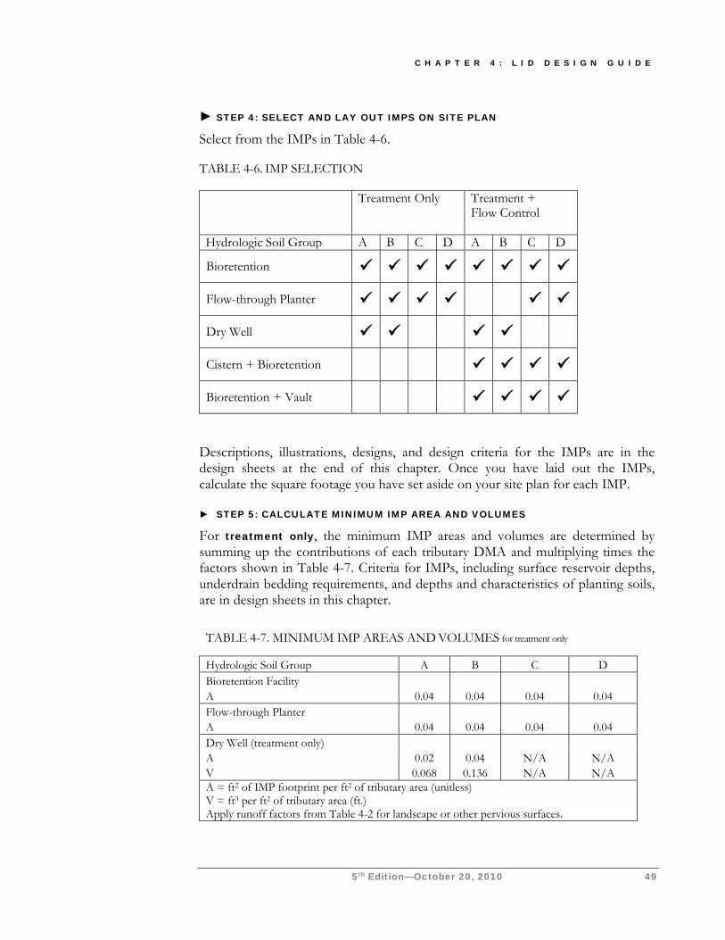
C H A P T E R 4 : L I D D E S I G N G U I D E
5th Edition—October 20, 2010 49
► STEP 4: SELECT AND LAY OUT IMPS ON SITE PLAN Select from the IMPs in Table 4-6.
TABLE 4-6. IMP SELECTION
Treatment Only Treatment + Flow Control
Hydrologic Soil Group A B C D A B C D
Bioretention
Flow-through Planter
Dry Well
Cistern + Bioretention
Bioretention + Vault
Descriptions, illustrations, designs, and design criteria for the IMPs are in the design sheets at the end of this chapter. Once you have laid out the IMPs, calculate the square footage you have set aside on your site plan for each IMP.
► STEP 5: CALCULATE MINIMUM IMP AREA AND VOLUMES
For treatment only, the minimum IMP areas and volumes are determined by summing up the contributions of each tributary DMA and multiplying times the factors shown in Table 4-7. Criteria for IMPs, including surface reservoir depths, underdrain bedding requirements, and depths and characteristics of planting soils, are in design sheets in this chapter.
TABLE 4-7. MINIMUM IMP AREAS AND VOLUMES for treatment only
Hydrologic Soil Group A B C D Bioretention Facility A 0.04 0.04 0.04 0.04 Flow-through Planter A 0.04 0.04 0.04 0.04 Dry Well (treatment only) A 0.02 0.04 N/A N/A V 0.068 0.136 N/A N/A A = ft2 of IMP footprint per ft2 of tributary area (unitless) V = ft3 per ft2 of tributary area (ft.) Apply runoff factors from Table 4-2 for landscape or other pervious surfaces.
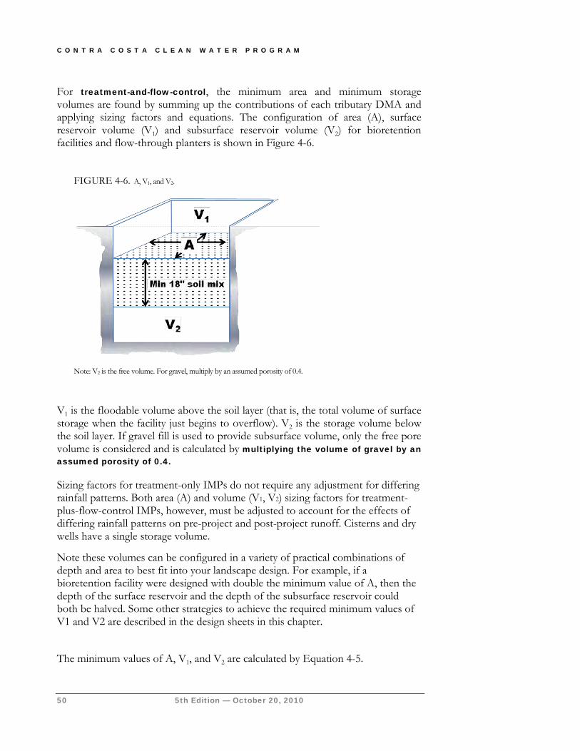
C O N T R A C O S T A C L E A N W A T E R P R O G R A M
50 5th Edition — October 20, 2010
FIGURE 4-6. A, V1, and V2.
Note: V2 is the free volume. For gravel, multiply by an assumed porosity of 0.4.
For treatment-and-flow-control, the minimum area and minimum storage volumes are found by summing up the contributions of each tributary DMA and applying sizing factors and equations. The configuration of area (A), surface reservoir volume (V1) and subsurface reservoir volume (V2) for bioretention facilities and flow-through planters is shown in Figure 4-6.
V1 is the floodable volume above the soil layer (that is, the total volume of surface storage when the facility just begins to overflow). V2 is the storage volume below the soil layer. If gravel fill is used to provide subsurface volume, only the free pore volume is considered and is calculated by multiplying the volume of gravel by an assumed porosity of 0.4.
Sizing factors for treatment-only IMPs do not require any adjustment for differing rainfall patterns. Both area (A) and volume (V1, V2) sizing factors for treatment-plus-flow-control IMPs, however, must be adjusted to account for the effects of differing rainfall patterns on pre-project and post-project runoff. Cisterns and dry wells have a single storage volume. Note these volumes can be configured in a variety of practical combinations of depth and area to best fit into your landscape design. For example, if a bioretention facility were designed with double the minimum value of A, then the depth of the surface reservoir and the depth of the subsurface reservoir could both be halved. Some other strategies to achieve the required minimum values of V1 and V2 are described in the design sheets in this chapter.
The minimum values of A, V1, and V2 are calculated by Equation 4-5.
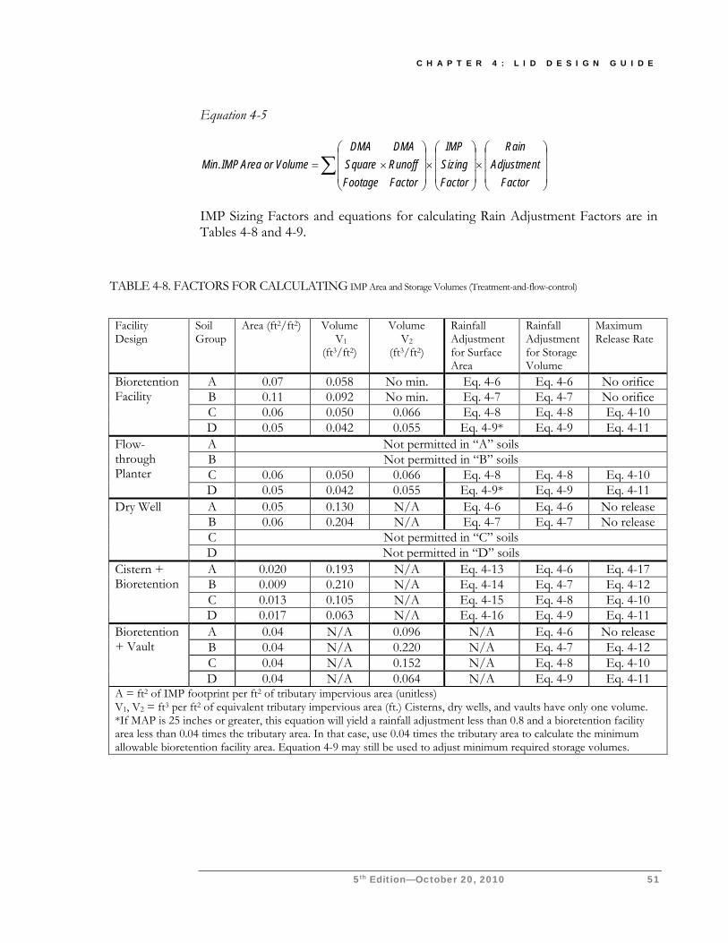
C H A P T E R 4 : L I D D E S I G N G U I D E
5th Edition—October 20, 2010 51
Equation 4-5
×
×
×
=∑
FactorAdjustment
Rain
FactorSizingIMP
FactorRunoffDMA
FootageSquareDMA
VolumeorAreaIMPMin.
IMP Sizing Factors and equations for calculating Rain Adjustment Factors are in Tables 4-8 and 4-9.
TABLE 4-8. FACTORS FOR CALCULATING IMP Area and Storage Volumes (Treatment-and-flow-control)
Facility Design
Soil Group
Area (ft2/ft2) Volume V1
(ft3/ft2)
Volume V2
(ft3/ft2)
Rainfall Adjustment for Surface Area
Rainfall Adjustment for Storage Volume
Maximum Release Rate
Bioretention Facility
A 0.07 0.058 No min. Eq. 4-6 Eq. 4-6 No orifice B 0.11 0.092 No min. Eq. 4-7 Eq. 4-7 No orifice C 0.06 0.050 0.066 Eq. 4-8 Eq. 4-8 Eq. 4-10 D 0.05 0.042 0.055 Eq. 4-9* Eq. 4-9 Eq. 4-11
Flow-through Planter
A Not permitted in “A” soils B Not permitted in “B” soils C 0.06 0.050 0.066 Eq. 4-8 Eq. 4-8 Eq. 4-10 D 0.05 0.042 0.055 Eq. 4-9* Eq. 4-9 Eq. 4-11
Dry Well A 0.05 0.130 N/A Eq. 4-6 Eq. 4-6 No release B 0.06 0.204 N/A Eq. 4-7 Eq. 4-7 No release C Not permitted in “C” soils D Not permitted in “D” soils
Cistern + Bioretention
A 0.020 0.193 N/A Eq. 4-13 Eq. 4-6 Eq. 4-17 B 0.009 0.210 N/A Eq. 4-14 Eq. 4-7 Eq. 4-12 C 0.013 0.105 N/A Eq. 4-15 Eq. 4-8 Eq. 4-10 D 0.017 0.063 N/A Eq. 4-16 Eq. 4-9 Eq. 4-11
Bioretention + Vault
A 0.04 N/A 0.096 N/A Eq. 4-6 No release B 0.04 N/A 0.220 N/A Eq. 4-7 Eq. 4-12 C 0.04 N/A 0.152 N/A Eq. 4-8 Eq. 4-10 D 0.04 N/A 0.064 N/A Eq. 4-9 Eq. 4-11
A = ft2 of IMP footprint per ft2 of tributary impervious area (unitless) V1, V2 = ft3 per ft2 of equivalent tributary impervious area (ft.) Cisterns, dry wells, and vaults have only one volume. *If MAP is 25 inches or greater, this equation will yield a rainfall adjustment less than 0.8 and a bioretention facility area less than 0.04 times the tributary area. In that case, use 0.04 times the tributary area to calculate the minimum allowable bioretention facility area. Equation 4-9 may still be used to adjust minimum required storage volumes.
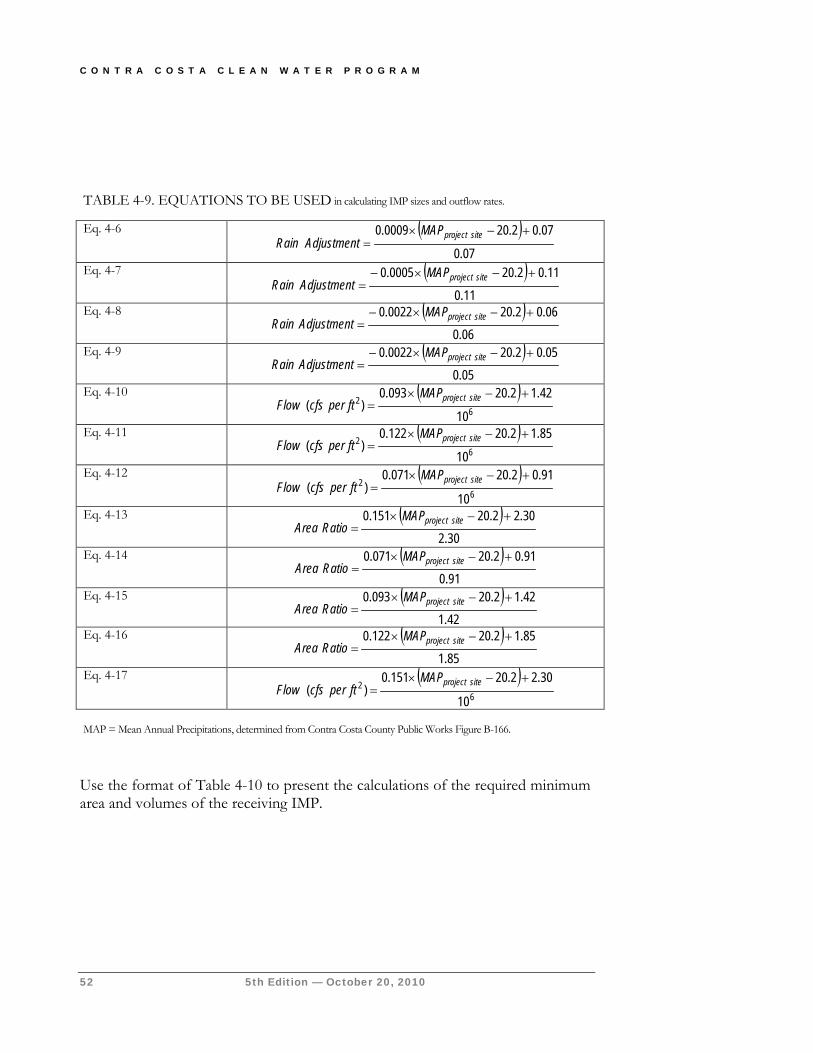
C O N T R A C O S T A C L E A N W A T E R P R O G R A M
52 5th Edition — October 20, 2010
Use the format of Table 4-10 to present the calculations of the required minimum area and volumes of the receiving IMP.
TABLE 4-9. EQUATIONS TO BE USED in calculating IMP sizes and outflow rates. Eq. 4-6 ( )
07.0
07.02.200009.0 +−×=
siteprojectMAPAdjustmentRain
Eq. 4-7 ( )11.0
11.02.200005.0 +−×−=
siteprojectMAPAdjustmentRain
Eq. 4-8 ( )06.0
06.02.200022.0 +−×−=
siteprojectMAPAdjustmentRain
Eq. 4-9 ( )05.0
05.02.200022.0 +−×−=
siteprojectMAPAdjustmentRain
Eq. 4-10 ( )6
2
10
42.12.20093.0)(
+−×=
siteprojectMAPftpercfsFlow
Eq. 4-11 ( )6
2
10
85.12.20122.0)(
+−×=
siteprojectMAPftpercfsFlow
Eq. 4-12 ( )6
2
10
91.02.20071.0)(
+−×=
siteprojectMAPftpercfsFlow
Eq. 4-13 ( )30.2
30.22.20151.0 +−×=
siteprojectMAPRatioArea
Eq. 4-14 ( )91.0
91.02.20071.0 +−×=
siteprojectMAPRatioArea
Eq. 4-15 ( )42.1
42.12.20093.0 +−×=
siteprojectMAPRatioArea
Eq. 4-16 ( )85.1
85.12.20122.0 +−×=
siteprojectMAPRatioArea
Eq. 4-17 ( )6
2
10
30.22.20151.0)(
+−×=
siteprojectMAPftpercfsFlow
MAP = Mean Annual Precipitations, determined from Contra Costa County Public Works Figure B-166.
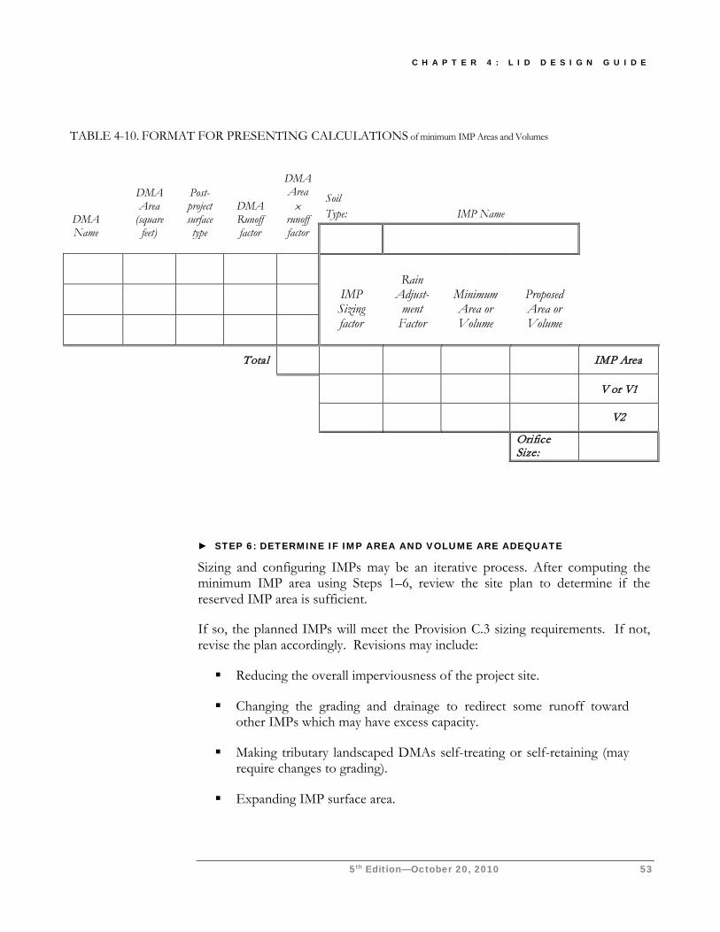
C H A P T E R 4 : L I D D E S I G N G U I D E
5th Edition—October 20, 2010 53
► STEP 6: DETERMINE IF IMP AREA AND VOLUME ARE ADEQUATE
Sizing and configuring IMPs may be an iterative process. After computing the minimum IMP area using Steps 1–6, review the site plan to determine if the reserved IMP area is sufficient.
If so, the planned IMPs will meet the Provision C.3 sizing requirements. If not, revise the plan accordingly. Revisions may include:
Reducing the overall imperviousness of the project site.
Changing the grading and drainage to redirect some runoff toward other IMPs which may have excess capacity.
Making tributary landscaped DMAs self-treating or self-retaining (may require changes to grading).
Expanding IMP surface area.
TABLE 4-10. FORMAT FOR PRESENTING CALCULATIONS of minimum IMP Areas and Volumes
DMA Name
DMA Area
(square feet)
Post-project surface type
DMA Runoff factor
DMA Area ×
runoff factor
Soil Type:
IMP Name
IMP Sizing factor
Rain Adjust-
ment Factor
Minimum Area or Volume
Proposed Area or Volume
Total IMP Area
V or V1
V2
Orifice Size:
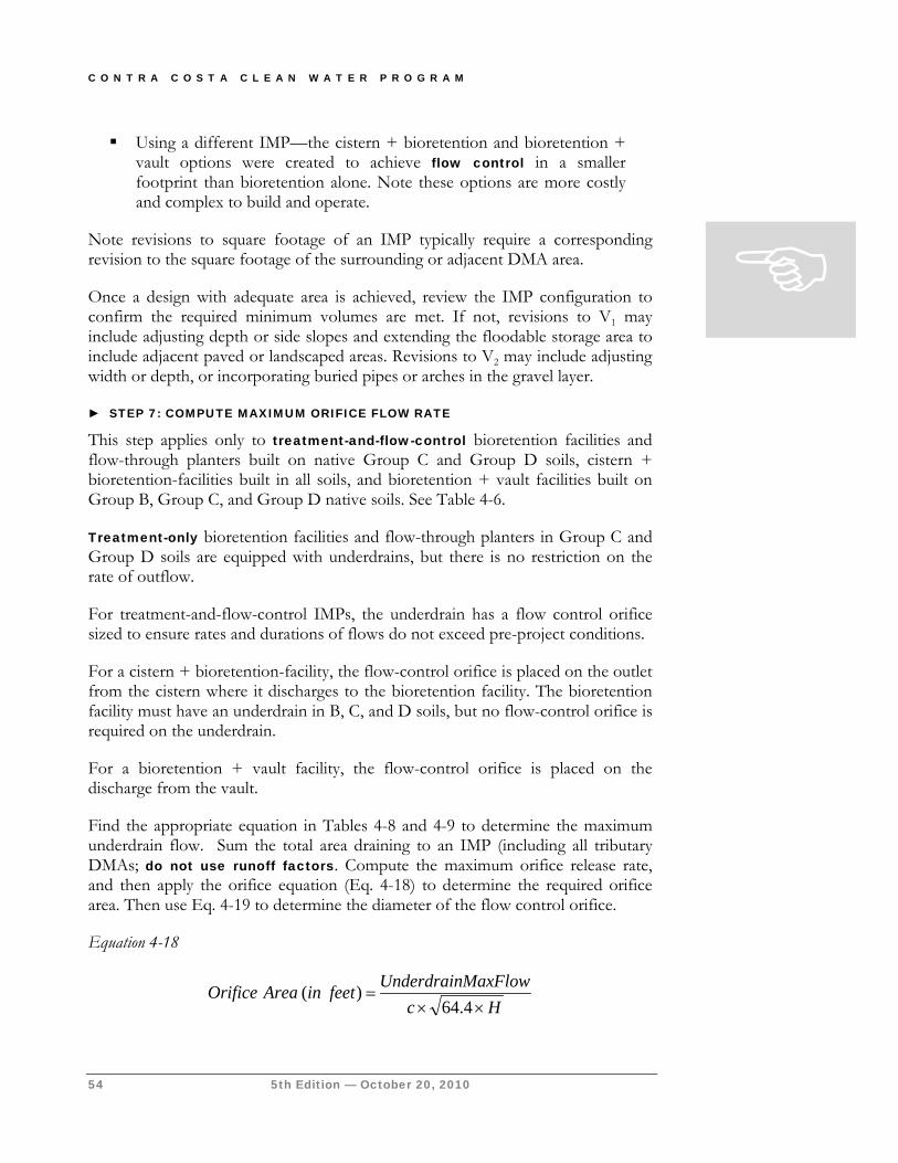
C O N T R A C O S T A C L E A N W A T E R P R O G R A M
54 5th Edition — October 20, 2010
Using a different IMP—the cistern + bioretention and bioretention + vault options were created to achieve flow control in a smaller footprint than bioretention alone. Note these options are more costly and complex to build and operate.
Note revisions to square footage of an IMP typically require a corresponding revision to the square footage of the surrounding or adjacent DMA area.
Once a design with adequate area is achieved, review the IMP configuration to confirm the required minimum volumes are met. If not, revisions to V1 may include adjusting depth or side slopes and extending the floodable storage area to include adjacent paved or landscaped areas. Revisions to V2 may include adjusting width or depth, or incorporating buried pipes or arches in the gravel layer.
► STEP 7: COMPUTE MAXIMUM ORIFICE FLOW RATE
This step applies only to treatment-and-flow-control bioretention facilities and flow-through planters built on native Group C and Group D soils, cistern + bioretention-facilities built in all soils, and bioretention + vault facilities built on Group B, Group C, and Group D native soils. See Table 4-6.
Treatment-only bioretention facilities and flow-through planters in Group C and Group D soils are equipped with underdrains, but there is no restriction on the rate of outflow.
For treatment-and-flow-control IMPs, the underdrain has a flow control orifice sized to ensure rates and durations of flows do not exceed pre-project conditions.
For a cistern + bioretention-facility, the flow-control orifice is placed on the outlet from the cistern where it discharges to the bioretention facility. The bioretention facility must have an underdrain in B, C, and D soils, but no flow-control orifice is required on the underdrain.
For a bioretention + vault facility, the flow-control orifice is placed on the discharge from the vault.
Find the appropriate equation in Tables 4-8 and 4-9 to determine the maximum underdrain flow. Sum the total area draining to an IMP (including all tributary DMAs; do not use runoff factors. Compute the maximum orifice release rate, and then apply the orifice equation (Eq. 4-18) to determine the required orifice area. Then use Eq. 4-19 to determine the diameter of the flow control orifice.
Equation 4-18
HcMaxFlowUnderdrainfeetinAreaOrifice××
=4.64
)(
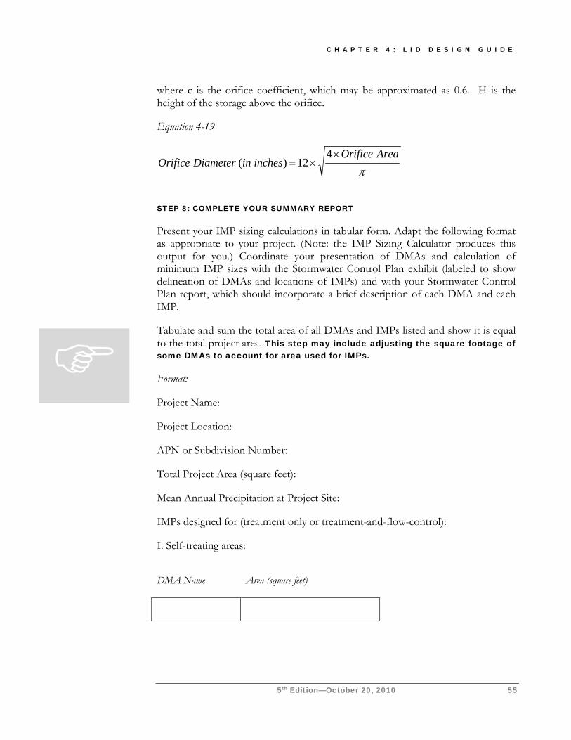
C H A P T E R 4 : L I D D E S I G N G U I D E
5th Edition—October 20, 2010 55
where c is the orifice coefficient, which may be approximated as 0.6. H is the height of the storage above the orifice.
Equation 4-19
πAreaOrifice
inchesinDiameterOrifice×
×=4
12)(
STEP 8: COMPLETE YOUR SUMMARY REPORT
Present your IMP sizing calculations in tabular form. Adapt the following format as appropriate to your project. (Note: the IMP Sizing Calculator produces this output for you.) Coordinate your presentation of DMAs and calculation of minimum IMP sizes with the Stormwater Control Plan exhibit (labeled to show delineation of DMAs and locations of IMPs) and with your Stormwater Control Plan report, which should incorporate a brief description of each DMA and each IMP.
Tabulate and sum the total area of all DMAs and IMPs listed and show it is equal to the total project area. This step may include adjusting the square footage of some DMAs to account for area used for IMPs.
Format:
Project Name:
Project Location:
APN or Subdivision Number:
Total Project Area (square feet):
Mean Annual Precipitation at Project Site:
IMPs designed for (treatment only or treatment-and-flow-control):
I. Self-treating areas:
DMA Name
Area (square feet)
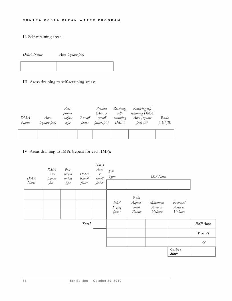
C O N T R A C O S T A C L E A N W A T E R P R O G R A M
56 5th Edition — October 20, 2010
II. Self-retaining areas:
DMA Name
Area (square feet)
III. Areas draining to self-retaining areas:
IV. Areas draining to IMPs (repeat for each IMP):
DMA Name
Area
(square feet)
Post-project surface type
Runoff factor
Product (Area x runoff
factor)[A]
Receiving
self- retaining DMA
Receiving self-
retaining DMA Area (square
feet) [B]
Ratio [A]/[B]
DMA Name
DMA Area
(square feet)
Post-project surface type
DMA Runoff factor
DMA Area ×
runoff factor
Soil Type:
IMP Name
IMP Sizing factor
Rain Adjust-
ment Factor
Minimum Area or Volume
Proposed Area or Volume
Total IMP Area
V or V1
V2
Orifice Size:
C H A P T E R 4 : L I D D E S I G N G U I D E
5th Edition—October 20, 2010 57
Specify Preliminary Design Details In your Stormwater Control Plan, describe your features and facilities in sufficient detail to demonstrate the area, volume, and other criteria of each can be met within the constraints of the site.
Ensure these details are consistent with preliminary site plans, landscaping plans, and architectural plans submitted with your application for planning and zoning approvals.
Following are design sheets for:
Self-treating and self-retaining areas
Pervious pavements
Bioretention
Flow-through planter
Dry well
Cistern + bioretention
Bioretention + vault
These design sheets include recommended configurations and details, and example applications, for these features and facilities. The information in these design sheets must be adapted and applied to the conditions specific to the development project. Local planning, building, and public works officials have final review and approval authority over the project design.
Keep in mind that proper and functional design of features and facilities is the responsibility of the applicant. Effective operation of facilities throughout the project’s lifetime will be the responsibility of the property owner.
Alternatives to LID Design LID has been found to be feasible for nearly all development sites. If you believe LID design may be infeasible for your development site, review the criteria for the selection of stormwater treatment facilities on page 16. If flow-control requirements apply, also review the options for compliance in Appendix C. Then consult with municipal staff before preparing an alternative design for stormwater treatment or flow-control.
C O N T R A C O S T A C L E A N W A T E R P R O G R A M
58 5th Edition — October 20, 2010
For all alternative designs, the applicant must submit a complete Stormwater Control Plan, including an exhibit showing the entire site divided into discrete Drainage Management Areas, text and tables showing how drainage is routed from each DMA to a treatment facility, and calculations demonstrating the design achieves the applicable design criteria for each facility.
► TREATMENT CONTROL ALTERNATIVES
Here are criteria and design considerations for alternatives that may be used under the conditions allowed by the permit and by the municipality:
Sand Filters. To ensure effectiveness is not compromised by compacting or clogging of the filter surface, sand filters must be maintained frequently.
The following criteria apply to sand filters:
Calculate the design flow using the rational method with an intensity of 0.2"/hour and the runoff factors for treatment only from Table 4-2.
To determine the required filter surface area, divide the design flow by an allowable maximum design surface loading rate of 5"/hour.
The minimum depth of filter media is 18". The media should be washed sand, with gradation similar to that specified for fine aggregate in ASTM C-33.
The entire filter area must be accessible for easy maintenance without the need to enter a confined space.
A typical filter design includes a gravel drain layer and a perforated pipe underdrain. Filter fabric may be used to prevent the filter media from entering the gravel layer.
The design should not include any permanent pool or other standing water. Instead of including a pretreatment basin, consider the following features in the area tributary to the filter to reduce the potential for filter clogging:
Limit the size of the Drainage Management Area.
Include only impervious areas in the DMA.
Stabilize slopes and eliminate sources of sediment in the DMA.
Provide screens for trash and leaves at storm drain inlets.
Pending Actions MRP Provision C.3.e.ii.(2)
requires the municipal permitees to submit types of
projects proposed for consideration of “LID
treatment reduction credits” to the Water Board by December
C H A P T E R 4 : L I D D E S I G N G U I D E
5th Edition—October 20, 2010 59
For additional design considerations and details, see Design of Stormwater Filtering Systems by Richard A. Claytor and Thomas R. Schueler, The Center for Watershed Protection, 1996, and California Stormwater BMP Handbooks Fact Sheet TC-40, Media Filter.
“Wet” Detention Ponds and Constructed Wetlands. The required detention volume is determined using the “Unit Basin Storage Size for 80% Capture” chart available on the CCCWP’s website and the mean annual precipitation determined from Contra Costa County Public Works Drawing B-166. . Before proceeding with design, contact the Contra Costa Mosquito and Vector Control District to coordinate the design and plan ongoing inspection and maintenance of the facility for mosquito control. For design considerations and details, see the California Stormwater Best Management Practices Handbooks, Fact Sheet TC-20, “Wet Ponds,” and Fact Sheet TC-21, “Constructed Wetlands.”
Higher-rate surface filters and vault-based filters. As described on page 16, these facilities may be used only in specific types of projects where other alternatives have proven infeasible. For surface filters, the grading and drainage design should minimize the area draining to each unit and maximize the number of discrete drainage areas and units. Proprietary facilities should be installed and maintained consistent with the manufacturer’s instructions.
► TREATMENT AND FLOW CONTROL ALTERNATIVES
By using the CCCWP’s design procedure, including LID IMPs, your project will meet requirements to minimize imperviousness, treat runoff, and control runoff peaks and durations. If the use of LID IMPs is not feasible, compliance with each of these requirements must be demonstrated individually. Separate facilities may be needed for treatment and for flow control.
If flow-control compliance is achieved by Options #1 or #4 in Appendix C, treatment compliance may be achieved by use of LID IMPs sized using treatment-only criteria.
Cistern with sand filter. Treatment and flow-control requirements can be met by using the cistern, including the volume calculated using Equation 4-5 and the discharge rate calculated using Equation 4-5 and Equation 4-17, 4-12, 4-10 or 4-11, and a sand filter sized to achieve a maximum surface loading rate of 5"/hour based on the calculated maximum discharge of the cistern orifice.*
* This option would not occur under the Program’s current policy. All development projects subject to HMP requirements are also subject to LID requirements. It is retained here for information pending further Water Board action.
C O N T R A C O S T A C L E A N W A T E R P R O G R A M
60 5th Edition — October 20, 2010
Treatment-and-flow-control detention basin, wet pond, or wetland. A detention basin may be sized and configured to achieve treatment and flow control:
The facility must contain a volume calculated using the “Unit Basin Storage Size for 80% capture” chart which has a drawdown time of 48 hours. To achieve maximum treatment effectiveness, this volume and discharge rate should be as close to the criteria as possible, neither oversized nor undersized.
The facility must also match pre-project peak flows and durations as must be shown using the modeling procedure described under Option #3 in Appendix C.
Applicants considering this option should consult with municipal staff and with the Contra Costa Mosquito and Vector Control District before proceeding with design.*
* This option would not occur under current policy. Detention basins and wetlands are suitable for drainage management areas larger than an acre; projects creating or replacing an acre or more of impervious area are always subject to LID requirements.
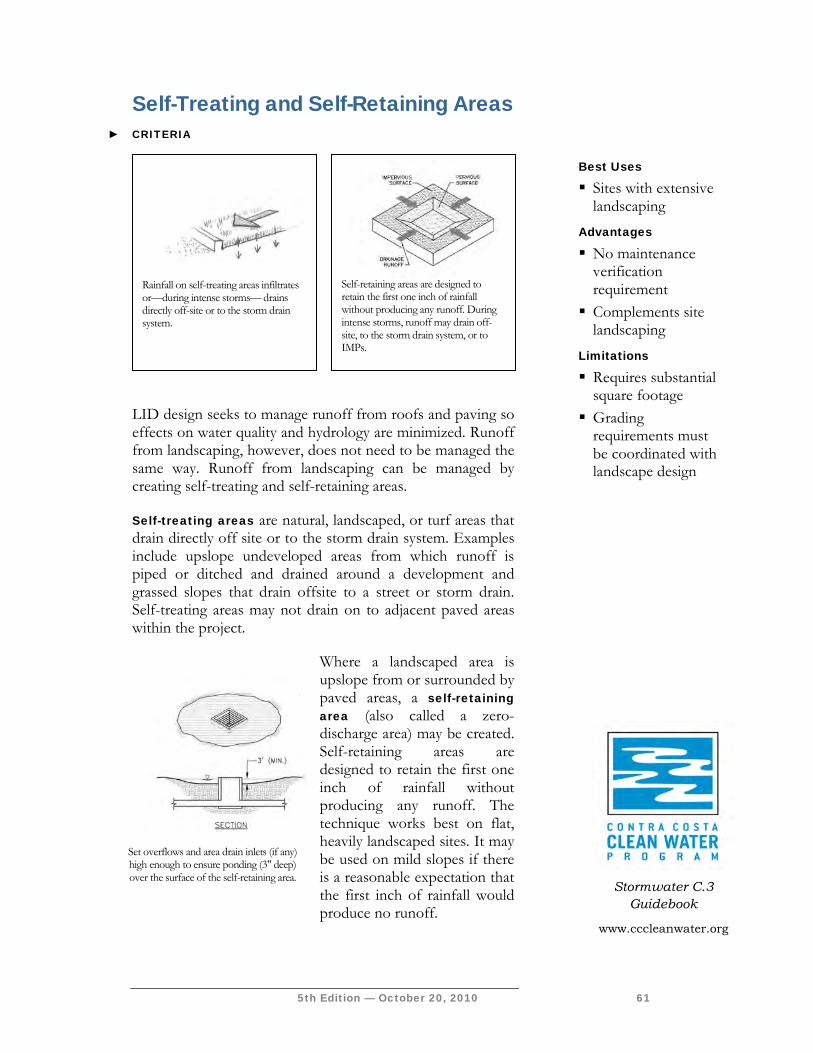
5th Edition — October 20, 2010 61
Self-Treating and Self-Retaining Areas ► CRITERIA
LID design seeks to manage runoff from roofs and paving so effects on water quality and hydrology are minimized. Runoff from landscaping, however, does not need to be managed the same way. Runoff from landscaping can be managed by creating self-treating and self-retaining areas.
Self-treating areas are natural, landscaped, or turf areas that drain directly off site or to the storm drain system. Examples include upslope undeveloped areas from which runoff is piped or ditched and drained around a development and grassed slopes that drain offsite to a street or storm drain. Self-treating areas may not drain on to adjacent paved areas within the project.
Where a landscaped area is upslope from or surrounded by paved areas, a self-retaining area (also called a zero-discharge area) may be created. Self-retaining areas are designed to retain the first one inch of rainfall without producing any runoff. The technique works best on flat, heavily landscaped sites. It may be used on mild slopes if there is a reasonable expectation that the first inch of rainfall would produce no runoff.
Best Uses
Sites with extensive landscaping
Advantages
No maintenance verification requirement
Complements site landscaping
Limitations
Requires substantial square footage
Grading requirements must be coordinated with landscape design
Rainfall on self-treating areas infiltrates or—during intense storms— drains directly off-site or to the storm drain system.
Stormwater C.3
Guidebook
www.cccleanwater.org
Self-retaining areas are designed to retain the first one inch of rainfall without producing any runoff. During intense storms, runoff may drain off-site, to the storm drain system, or to IMPs.
Set overflows and area drain inlets (if any) high enough to ensure ponding (3" deep) over the surface of the self-retaining area.
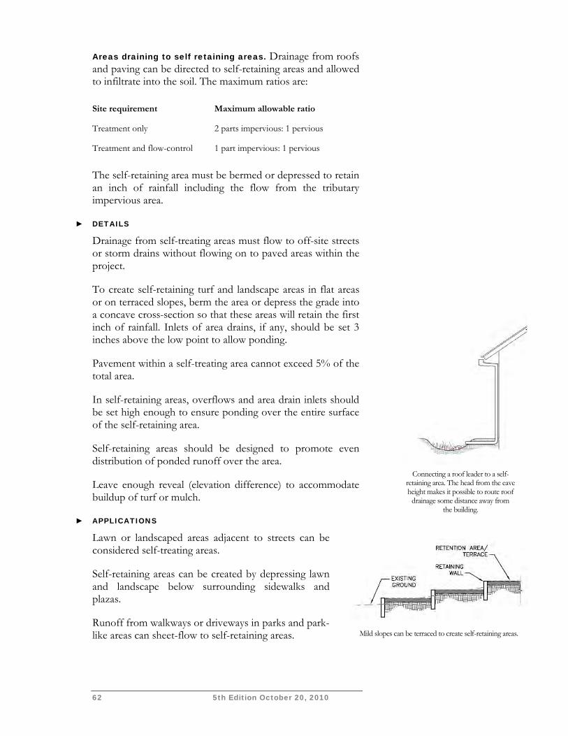
62 5th Edition October 20, 2010
Areas draining to self retaining areas. Drainage from roofs and paving can be directed to self-retaining areas and allowed to infiltrate into the soil. The maximum ratios are:
Site requirement Maximum allowable ratio
Treatment only 2 parts impervious: 1 pervious
Treatment and flow-control 1 part impervious: 1 pervious
The self-retaining area must be bermed or depressed to retain an inch of rainfall including the flow from the tributary impervious area.
► DETAILS
Drainage from self-treating areas must flow to off-site streets or storm drains without flowing on to paved areas within the project.
To create self-retaining turf and landscape areas in flat areas or on terraced slopes, berm the area or depress the grade into a concave cross-section so that these areas will retain the first inch of rainfall. Inlets of area drains, if any, should be set 3 inches above the low point to allow ponding.
Pavement within a self-treating area cannot exceed 5% of the total area.
In self-retaining areas, overflows and area drain inlets should be set high enough to ensure ponding over the entire surface of the self-retaining area.
Self-retaining areas should be designed to promote even distribution of ponded runoff over the area.
Leave enough reveal (elevation difference) to accommodate buildup of turf or mulch.
► APPLICATIONS
Lawn or landscaped areas adjacent to streets can be considered self-treating areas.
Self-retaining areas can be created by depressing lawn and landscape below surrounding sidewalks and plazas.
Runoff from walkways or driveways in parks and park-like areas can sheet-flow to self-retaining areas.
Mild slopes can be terraced to create self-retaining areas.
Connecting a roof leader to a self-
retaining area. The head from the eave height makes it possible to route roof
drainage some distance away from the building.
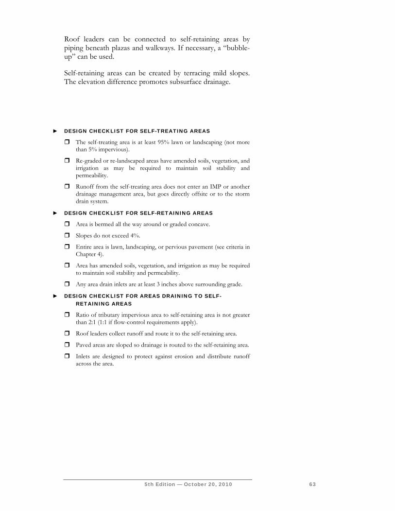
5th Edition — October 20, 2010 63
Roof leaders can be connected to self-retaining areas by piping beneath plazas and walkways. If necessary, a “bubble-up” can be used.
Self-retaining areas can be created by terracing mild slopes. The elevation difference promotes subsurface drainage.
► DESIGN CHECKLIST FOR SELF-TREATING AREAS
The self-treating area is at least 95% lawn or landscaping (not more than 5% impervious).
Re-graded or re-landscaped areas have amended soils, vegetation, and irrigation as may be required to maintain soil stability and permeability.
Runoff from the self-treating area does not enter an IMP or another drainage management area, but goes directly offsite or to the storm drain system.
► DESIGN CHECKLIST FOR SELF-RETAINING AREAS
Area is bermed all the way around or graded concave.
Slopes do not exceed 4%.
Entire area is lawn, landscaping, or pervious pavement (see criteria in Chapter 4).
Area has amended soils, vegetation, and irrigation as may be required to maintain soil stability and permeability.
Any area drain inlets are at least 3 inches above surrounding grade.
► DESIGN CHECKLIST FOR AREAS DRAINING TO SELF-RETAINING AREAS
Ratio of tributary impervious area to self-retaining area is not greater than 2:1 (1:1 if flow-control requirements apply).
Roof leaders collect runoff and route it to the self-retaining area.
Paved areas are sloped so drainage is routed to the self-retaining area.
Inlets are designed to protect against erosion and distribute runoff across the area.

64 5th Edition October 20, 2010
This page intentionally left blank.
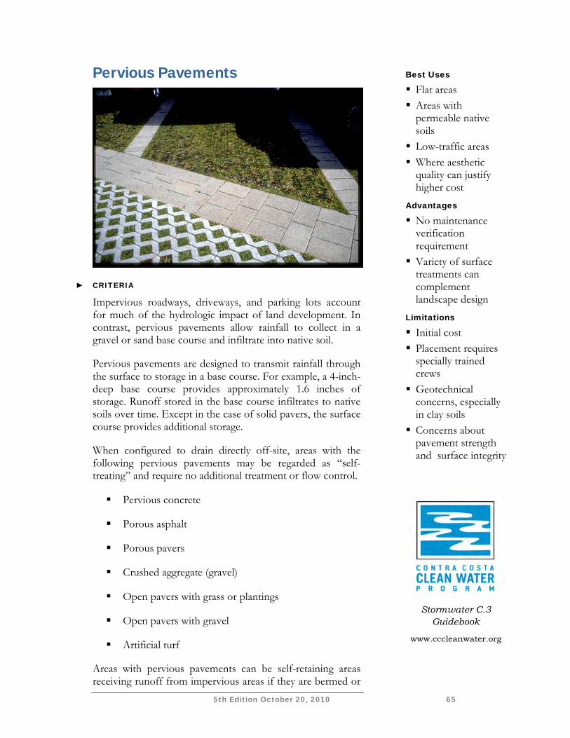
5th Edition October 20, 2010 65
Pervious Pavements
► CRITERIA
Impervious roadways, driveways, and parking lots account for much of the hydrologic impact of land development. In contrast, pervious pavements allow rainfall to collect in a gravel or sand base course and infiltrate into native soil.
Pervious pavements are designed to transmit rainfall through the surface to storage in a base course. For example, a 4-inch-deep base course provides approximately 1.6 inches of storage. Runoff stored in the base course infiltrates to native soils over time. Except in the case of solid pavers, the surface course provides additional storage.
When configured to drain directly off-site, areas with the following pervious pavements may be regarded as “self-treating” and require no additional treatment or flow control.
Pervious concrete
Porous asphalt
Porous pavers
Crushed aggregate (gravel)
Open pavers with grass or plantings
Open pavers with gravel
Artificial turf
Areas with pervious pavements can be self-retaining areas receiving runoff from impervious areas if they are bermed or
Best Uses
Flat areas Areas with
permeable native soils
Low-traffic areas Where aesthetic
quality can justify higher cost
Advantages
No maintenance verification requirement
Variety of surface treatments can complement landscape design
Limitations
Initial cost Placement requires
specially trained crews
Geotechnical concerns, especially in clay soils
Concerns about pavement strength and surface integrity
Stormwater C.3
Guidebook
www.cccleanwater.org
66 5th Edition October 20, 2010
depressed to retain the first one inch of rainfall, including runoff from any tributary impervious areas.
Solid unit pavers—such as bricks, stone blocks, or precast concrete shapes—are considered to reduce runoff compared to impervious pavement, when the unit pavers are set in sand or gravel with " gaps between the pavers. Joints must be filled with an open-graded aggregate free of fines.
Use the runoff factors in Table 4-2.
► DETAILS
Permeable pavements can be used in clay soils; however, special design considerations, including an increased depth of base course, typically apply and will increase the cost of this option. Geotechnical fabric between the base course and underlying clay soil is recommended.
Permeable pavements are best used on grades from flat to approximately 2%. Installations on steeper grades, particularly on clay soils, require cut-off trenches lateral to the slope to intercept, store, and infiltrate drainage from the base course.
Pavement strength and durability typically determines the required depth of base course. If underdrains are used, the outlet elevation must be a minimum of 3 inches above the bottom elevation of the base course.
Pervious concrete and porous asphalt must be installed by crews with special training and tools. Industry associations maintain lists of qualified contractors.
Parking lots with crushed aggregate or unit pavers may require signs or bollards to organize parking.
5th Edition October 20, 2010 67
► DESIGN CHECKLIST FOR PERVIOUS PAVEMENTS
No erodible areas drain on to pavement.
Subgrade is uniform. Compaction is minimal.
Reservoir base course is of open-graded crushed stone. Base depth is adequate to retain rainfall and support design loads.
If a subdrain is provided, outlet elevation is a minimum of 3 inches above bottom of base course.
Subgrade is uniform and slopes are not so steep that subgrade is prone to erosion.
Rigid edge is provided to retain granular pavements and unit pavers.
Solid unit pavers are set in sand or gravel with minimum " gaps between the pavers. Joints are filled with an open-graded aggregate free of fines.
Permeable pavements are installed by industry-certified professionals according to vendor’s recommendations.
Selection and location of pavements incorporates Americans with Disabilities Act requirements, site aesthetics, and uses.
► RESOURCES
Concrete Promotion Council of Northern California www.concreteresources.net.
California Asphalt Pavement Association http://www.californiapavements.org/stormwater.html
Interlocking Concrete Pavement Institute http://www.icpi.org/
Start at the Source Design Manual for Water Quality Protection, pp. 47-53.
Porous Pavements, by Bruce K. Ferguson. 2005. ISBN 0-8493-2670-2.

68 5th Edition October 20, 2010
This page intentionally left blank.
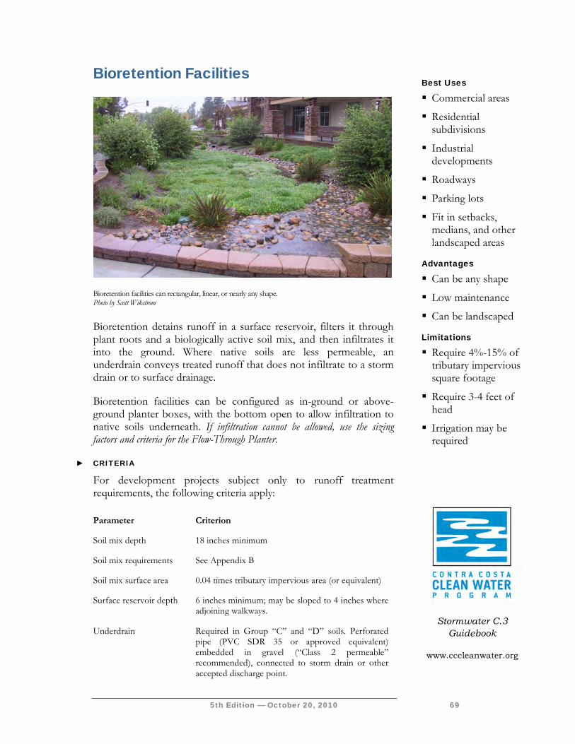
5th Edition — October 20, 2010 69
Bioretention Facilities
Bioretention detains runoff in a surface reservoir, filters it through plant roots and a biologically active soil mix, and then infiltrates it into the ground. Where native soils are less permeable, an underdrain conveys treated runoff that does not infiltrate to a storm drain or to surface drainage.
Bioretention facilities can be configured as in-ground or above-ground planter boxes, with the bottom open to allow infiltration to native soils underneath. If infiltration cannot be allowed, use the sizing factors and criteria for the Flow-Through Planter.
► CRITERIA
For development projects subject only to runoff treatment requirements, the following criteria apply:
Parameter Criterion
Soil mix depth 18 inches minimum
Soil mix requirements See Appendix B
Soil mix surface area 0.04 times tributary impervious area (or equivalent)
Surface reservoir depth 6 inches minimum; may be sloped to 4 inches where adjoining walkways.
Underdrain Required in Group “C” and “D” soils. Perforated pipe (PVC SDR 35 or approved equivalent) embedded in gravel (“Class 2 permeable” recommended), connected to storm drain or other accepted discharge point.
Best Uses
Commercial areas
Residential subdivisions
Industrial developments
Roadways
Parking lots
Fit in setbacks, medians, and other landscaped areas
Advantages
Can be any shape
Low maintenance
Can be landscaped
Limitations
Require 4%-15% of tributary impervious square footage
Require 3-4 feet of head
Irrigation may be required
Bioretention facilities can rectangular, linear, or nearly any shape. Photo by Scott Wikstrom
Stormwater C.3 Guidebook
www.cccleanwater.org
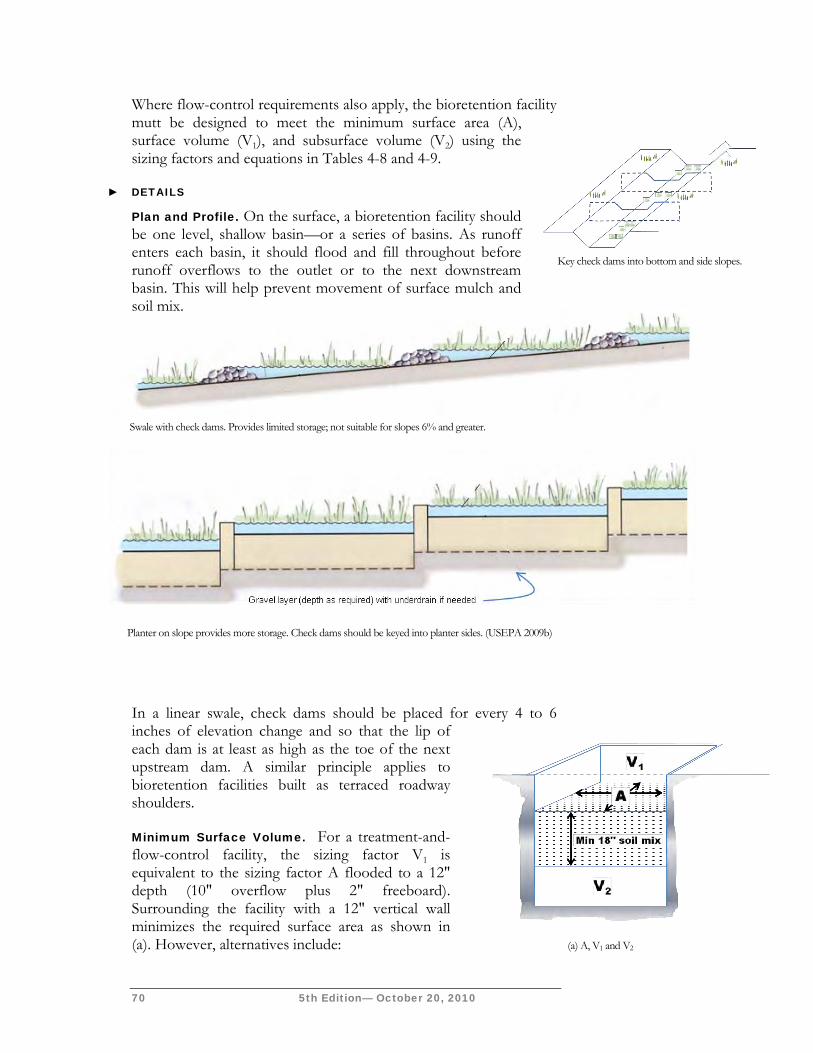
70 5th Edition— October 20, 2010
Swale with check dams. Provides limited storage; not suitable for slopes 6% and greater.
Planter on slope provides more storage. Check dams should be keyed into planter sides. (USEPA 2009b)
Where flow-control requirements also apply, the bioretention facility mutt be designed to meet the minimum surface area (A), surface volume (V1), and subsurface volume (V2) using the sizing factors and equations in Tables 4-8 and 4-9.
► DETAILS
Plan and Profile. On the surface, a bioretention facility should be one level, shallow basin—or a series of basins. As runoff enters each basin, it should flood and fill throughout before runoff overflows to the outlet or to the next downstream basin. This will help prevent movement of surface mulch and soil mix.
In a linear swale, check dams should be placed for every 4 to 6 inches of elevation change and so that the lip of each dam is at least as high as the toe of the next upstream dam. A similar principle applies to bioretention facilities built as terraced roadway shoulders.
Minimum Surface Volume. For a treatment-and-flow-control facility, the sizing factor V1 is equivalent to the sizing factor A flooded to a 12" depth (10" overflow plus 2" freeboard). Surrounding the facility with a 12" vertical wall minimizes the required surface area as shown in (a). However, alternatives include:
(a) A, V1 and V2
Key check dams into bottom and side slopes.
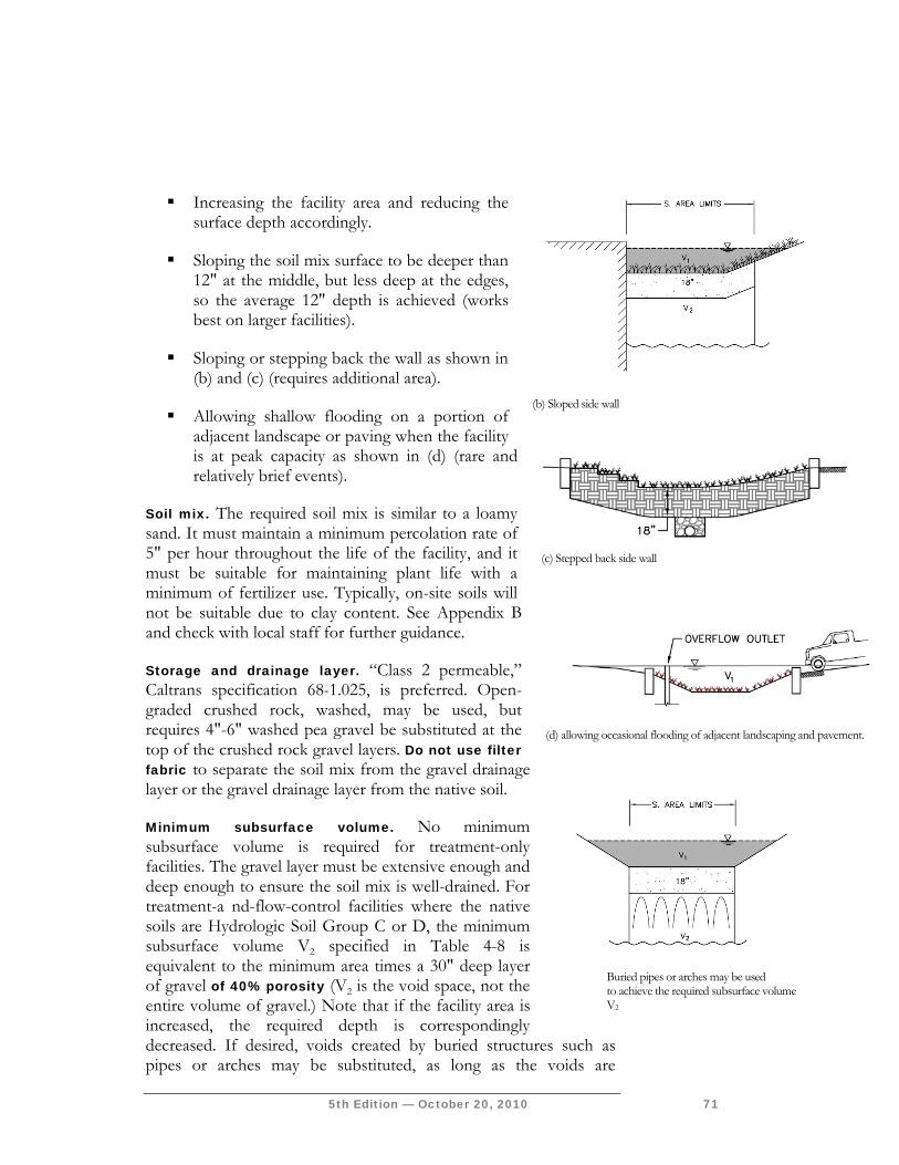
5th Edition — October 20, 2010 71
Increasing the facility area and reducing the surface depth accordingly.
Sloping the soil mix surface to be deeper than 12" at the middle, but less deep at the edges, so the average 12" depth is achieved (works best on larger facilities).
Sloping or stepping back the wall as shown in (b) and (c) (requires additional area).
Allowing shallow flooding on a portion of adjacent landscape or paving when the facility is at peak capacity as shown in (d) (rare and relatively brief events).
Soil mix. The required soil mix is similar to a loamy sand. It must maintain a minimum percolation rate of 5" per hour throughout the life of the facility, and it must be suitable for maintaining plant life with a minimum of fertilizer use. Typically, on-site soils will not be suitable due to clay content. See Appendix B and check with local staff for further guidance.
Storage and drainage layer. “Class 2 permeable,” Caltrans specification 68-1.025, is preferred. Open-graded crushed rock, washed, may be used, but requires 4"-6" washed pea gravel be substituted at the top of the crushed rock gravel layers. Do not use filter fabric to separate the soil mix from the gravel drainage layer or the gravel drainage layer from the native soil.
Minimum subsurface volume. No minimum subsurface volume is required for treatment-only facilities. The gravel layer must be extensive enough and deep enough to ensure the soil mix is well-drained. For treatment-a nd-flow-control facilities where the native soils are Hydrologic Soil Group C or D, the minimum subsurface volume V2 specified in Table 4-8 is equivalent to the minimum area times a 30" deep layer of gravel of 40% porosity (V2 is the void space, not the entire volume of gravel.) Note that if the facility area is increased, the required depth is correspondingly decreased. If desired, voids created by buried structures such as pipes or arches may be substituted, as long as the voids are
(d) allowing occasional flooding of adjacent landscaping and pavement.
(c) Stepped back side wall
Buried pipes or arches may be used to achieve the required subsurface volume V2
(b) Sloped side wall
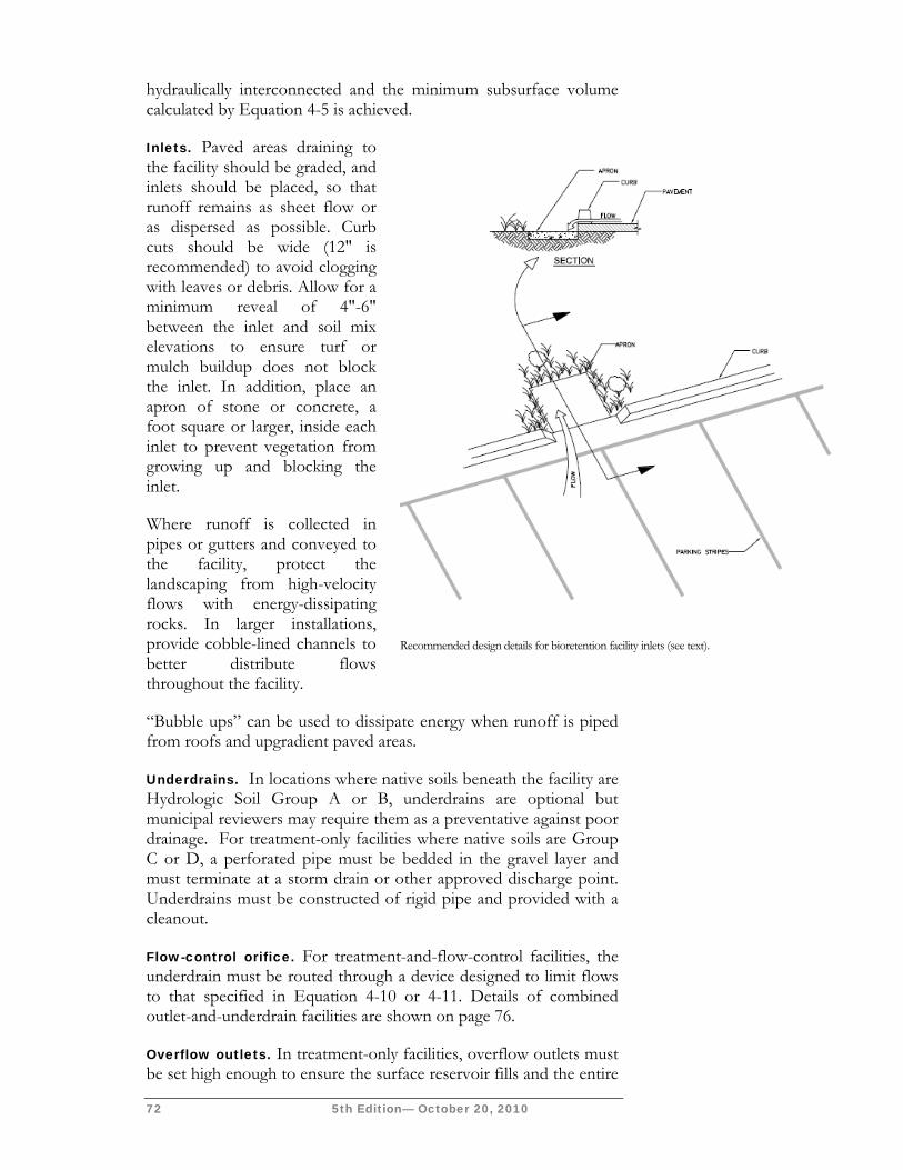
72 5th Edition— October 20, 2010
hydraulically interconnected and the minimum subsurface volume calculated by Equation 4-5 is achieved.
Inlets. Paved areas draining to the facility should be graded, and inlets should be placed, so that runoff remains as sheet flow or as dispersed as possible. Curb cuts should be wide (12" is recommended) to avoid clogging with leaves or debris. Allow for a minimum reveal of 4"-6" between the inlet and soil mix elevations to ensure turf or mulch buildup does not block the inlet. In addition, place an apron of stone or concrete, a foot square or larger, inside each inlet to prevent vegetation from growing up and blocking the inlet.
Where runoff is collected in pipes or gutters and conveyed to the facility, protect the landscaping from high-velocity flows with energy-dissipating rocks. In larger installations, provide cobble-lined channels to better distribute flows throughout the facility.
“Bubble ups” can be used to dissipate energy when runoff is piped from roofs and upgradient paved areas.
Underdrains. In locations where native soils beneath the facility are Hydrologic Soil Group A or B, underdrains are optional but municipal reviewers may require them as a preventative against poor drainage. For treatment-only facilities where native soils are Group C or D, a perforated pipe must be bedded in the gravel layer and must terminate at a storm drain or other approved discharge point. Underdrains must be constructed of rigid pipe and provided with a cleanout.
Flow-control orifice. For treatment-and-flow-control facilities, the underdrain must be routed through a device designed to limit flows to that specified in Equation 4-10 or 4-11. Details of combined outlet-and-underdrain facilities are shown on page 76.
Overflow outlets. In treatment-only facilities, overflow outlets must be set high enough to ensure the surface reservoir fills and the entire
Recommended design details for bioretention facility inlets (see text).
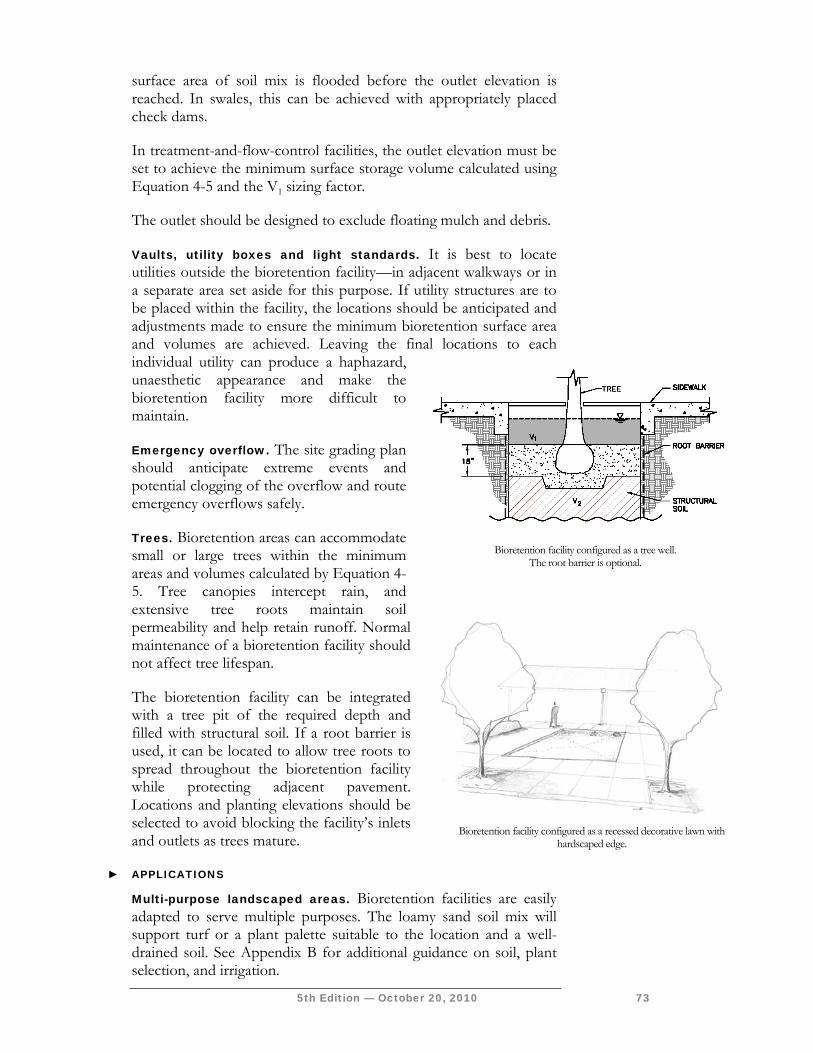
5th Edition — October 20, 2010 73
surface area of soil mix is flooded before the outlet elevation is reached. In swales, this can be achieved with appropriately placed check dams.
In treatment-and-flow-control facilities, the outlet elevation must be set to achieve the minimum surface storage volume calculated using Equation 4-5 and the V1 sizing factor.
The outlet should be designed to exclude floating mulch and debris.
Vaults, utility boxes and light standards. It is best to locate utilities outside the bioretention facility—in adjacent walkways or in a separate area set aside for this purpose. If utility structures are to be placed within the facility, the locations should be anticipated and adjustments made to ensure the minimum bioretention surface area and volumes are achieved. Leaving the final locations to each individual utility can produce a haphazard, unaesthetic appearance and make the bioretention facility more difficult to maintain.
Emergency overflow. The site grading plan should anticipate extreme events and potential clogging of the overflow and route emergency overflows safely.
Trees. Bioretention areas can accommodate small or large trees within the minimum areas and volumes calculated by Equation 4-5. Tree canopies intercept rain, and extensive tree roots maintain soil permeability and help retain runoff. Normal maintenance of a bioretention facility should not affect tree lifespan.
The bioretention facility can be integrated with a tree pit of the required depth and filled with structural soil. If a root barrier is used, it can be located to allow tree roots to spread throughout the bioretention facility while protecting adjacent pavement. Locations and planting elevations should be selected to avoid blocking the facility’s inlets and outlets as trees mature.
► APPLICATIONS
Multi-purpose landscaped areas. Bioretention facilities are easily adapted to serve multiple purposes. The loamy sand soil mix will support turf or a plant palette suitable to the location and a well-drained soil. See Appendix B for additional guidance on soil, plant selection, and irrigation.
Bioretention facility configured as a tree well.
The root barrier is optional.
Bioretention facility configured as a recessed decorative lawn with
hardscaped edge.
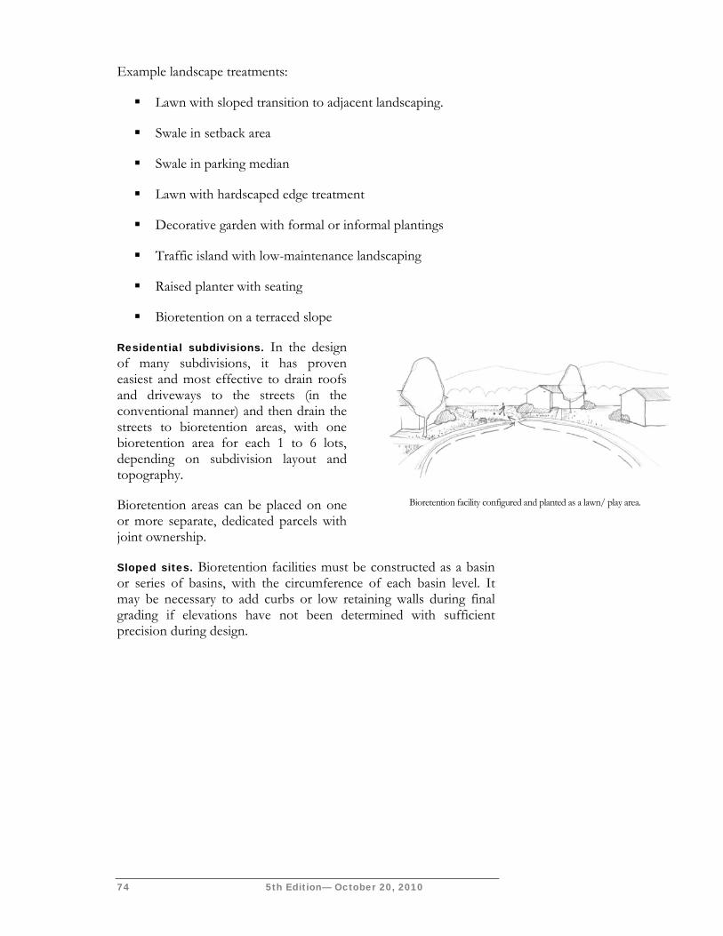
74 5th Edition— October 20, 2010
Example landscape treatments:
Lawn with sloped transition to adjacent landscaping.
Swale in setback area
Swale in parking median
Lawn with hardscaped edge treatment
Decorative garden with formal or informal plantings
Traffic island with low-maintenance landscaping
Raised planter with seating
Bioretention on a terraced slope
Residential subdivisions. In the design of many subdivisions, it has proven easiest and most effective to drain roofs and driveways to the streets (in the conventional manner) and then drain the streets to bioretention areas, with one bioretention area for each 1 to 6 lots, depending on subdivision layout and topography.
Bioretention areas can be placed on one or more separate, dedicated parcels with joint ownership.
Sloped sites. Bioretention facilities must be constructed as a basin or series of basins, with the circumference of each basin level. It may be necessary to add curbs or low retaining walls during final grading if elevations have not been determined with sufficient precision during design.
Bioretention facility configured and planted as a lawn/ play area.
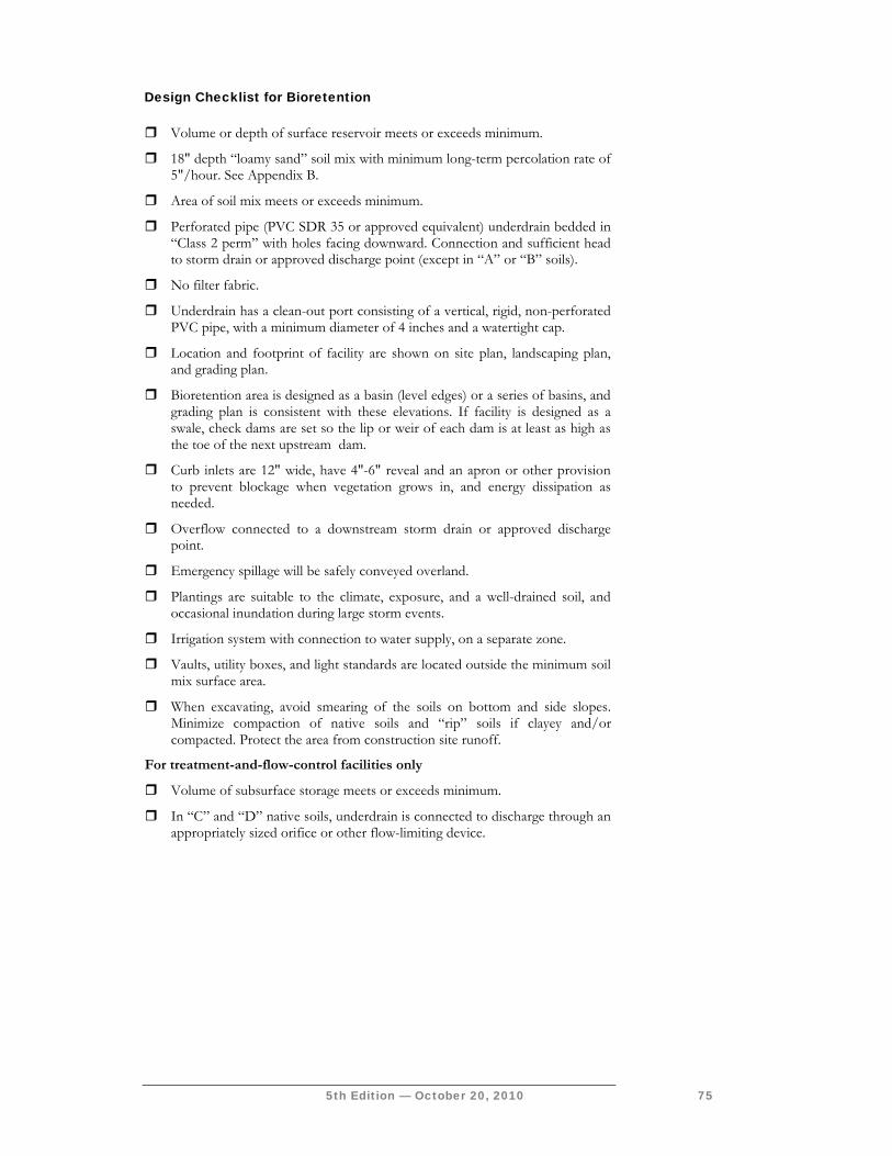
5th Edition — October 20, 2010 75
Design Checklist for Bioretention Volume or depth of surface reservoir meets or exceeds minimum.
18" depth “loamy sand” soil mix with minimum long-term percolation rate of 5"/hour. See Appendix B.
Area of soil mix meets or exceeds minimum.
Perforated pipe (PVC SDR 35 or approved equivalent) underdrain bedded in “Class 2 perm” with holes facing downward. Connection and sufficient head to storm drain or approved discharge point (except in “A” or “B” soils).
No filter fabric.
Underdrain has a clean-out port consisting of a vertical, rigid, non-perforated PVC pipe, with a minimum diameter of 4 inches and a watertight cap.
Location and footprint of facility are shown on site plan, landscaping plan, and grading plan.
Bioretention area is designed as a basin (level edges) or a series of basins, and grading plan is consistent with these elevations. If facility is designed as a swale, check dams are set so the lip or weir of each dam is at least as high as the toe of the next upstream dam.
Curb inlets are 12" wide, have 4"-6" reveal and an apron or other provision to prevent blockage when vegetation grows in, and energy dissipation as needed.
Overflow connected to a downstream storm drain or approved discharge point.
Emergency spillage will be safely conveyed overland.
Plantings are suitable to the climate, exposure, and a well-drained soil, and occasional inundation during large storm events.
Irrigation system with connection to water supply, on a separate zone.
Vaults, utility boxes, and light standards are located outside the minimum soil mix surface area.
When excavating, avoid smearing of the soils on bottom and side slopes. Minimize compaction of native soils and “rip” soils if clayey and/or compacted. Protect the area from construction site runoff.
For treatment-and-flow-control facilities only
Volume of subsurface storage meets or exceeds minimum.
In “C” and “D” native soils, underdrain is connected to discharge through an appropriately sized orifice or other flow-limiting device.
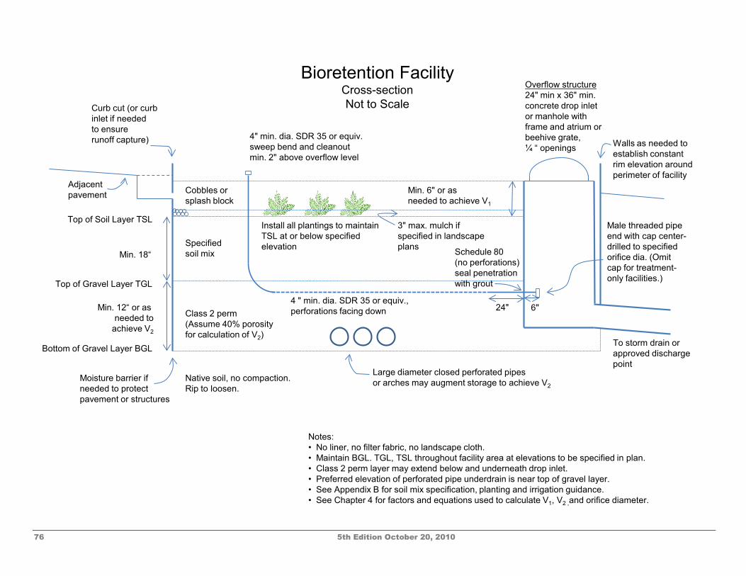
76 5th Edition October 20, 2010
Native soil, no compaction. Rip to loosen.
Class 2 perm(Assume 40% porosityfor calculation of V2)
Min. 12“ or as needed to
achieve V2
Min. 18“ Specified soil mix
3" max. mulch if specified in landscape plans
Min. 6" or asneeded to achieve V1
Curb cut (or curbinlet if neededto ensure runoff capture) 4" min. dia. SDR 35 or equiv.
sweep bend and cleanoutmin. 2" above overflow level
4 " min. dia. SDR 35 or equiv., perforations facing down
Top of Gravel Layer TGL
Bottom of Gravel Layer BGL
Top of Soil Layer TSL
Overflow structure24" min x 36" min.concrete drop inletor manhole with frame and atrium or beehive grate, ¼ “ openings
Schedule 80 (no perforations)seal penetration with grout
Male threaded pipe end with cap center-drilled to specified orifice dia. (Omit cap for treatment-only facilities.)
24" 6"
To storm drain or approved discharge point
Notes:• No liner, no filter fabric, no landscape cloth.• Maintain BGL. TGL, TSL throughout facility area at elevations to be specified in plan.• Class 2 perm layer may extend below and underneath drop inlet.• Preferred elevation of perforated pipe underdrain is near top of gravel layer.• See Appendix B for soil mix specification, planting and irrigation guidance.• See Chapter 4 for factors and equations used to calculate V1, V2 ,and orifice diameter.
Install all plantings to maintainTSL at or below specifiedelevation
Cobbles or splash block
Adjacent pavement
Moisture barrier ifneeded to protectpavement or structures
Bioretention FacilityCross-section Not to Scale
Large diameter closed perforated pipesor arches may augment storage to achieve V2
Walls as needed toestablish constant rim elevation around perimeter of facility
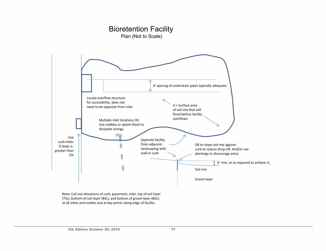
5th Edition October 20, 2010 77
Bioretention FacilityPlan (Not to Scale)
OK to slope soil mix againstcurb to reduce drop-off. And/or useplantings to discourage entry
Soil mix
Gravel layer
Separate facility from adjacentlandscaping with wall or curb
Multiple inlet locations OK. Use cobbles or splash block to dissipate energy.
Usecurb inletsif slope is
greater than2%
Locate overflow structure for accessibility; does notneed to be opposite from inlet
6" min. or as required to achieve V1
A = Surface area of soil mix that will flood before facility overflows
6' spacing of underdrain pipes typically adequate
Note: Call out elevations of curb, pavement, inlet, top of soil layer (TSL), bottom of soil layer (BSL), and bottom of gravel layer (BGL) at all inlets and outlets and at key points along edge of facility.

78 5th Edition October 20, 2010
This page intentionally left blank.
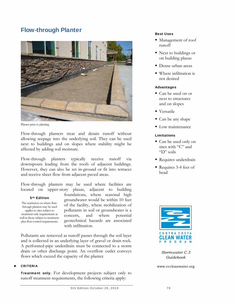
5th Edition October 20, 2010 79
Flow-through Planter
Planter prior to planting
Flow-through planters treat and detain runoff without allowing seepage into the underlying soil. They can be used next to buildings and on slopes where stability might be affected by adding soil moisture.
Flow-through planters typically receive runoff via downspouts leading from the roofs of adjacent buildings. However, they can also be set in-ground or fit into terraces and receive sheet flow from adjacent paved areas.
Flow-through planters may be used where facilities are located on upper-story plazas, adjacent to building
foundations, where seasonal high groundwater would be within 10 feet of the facility, where mobilization of pollutants in soil or groundwater is a concern, and where potential geotechnical hazards are associated with infiltration.
Pollutants are removed as runoff passes through the soil layer and is collected in an underlying layer of gravel or drain rock. A perforated-pipe underdrain must be connected to a storm drain or other discharge point. An overflow outlet conveys flows which exceed the capacity of the planter.
► CRITERIA
Treatment only. For development projects subject only to runoff treatment requirements, the following criteria apply:
5th Edition The restriction on where flow-through planters may be used
applies to sites subject to treatment-only requirements as
well as those subject to treatment-plus-flow-control requirements.
Best Uses
Management of roof runoff
Next to buildings or on building plazas
Dense urban areas
Where infiltration is not desired
Advantages
Can be used on or next to structures and on slopes
Versatile
Can be any shape
Low maintenance
Limitations
Can be used only on sites with “C” and “D” soils
Requires underdrain
Requires 3-4 feet of head
Stormwater C.3 Guidebook
www.cccleanwater.org
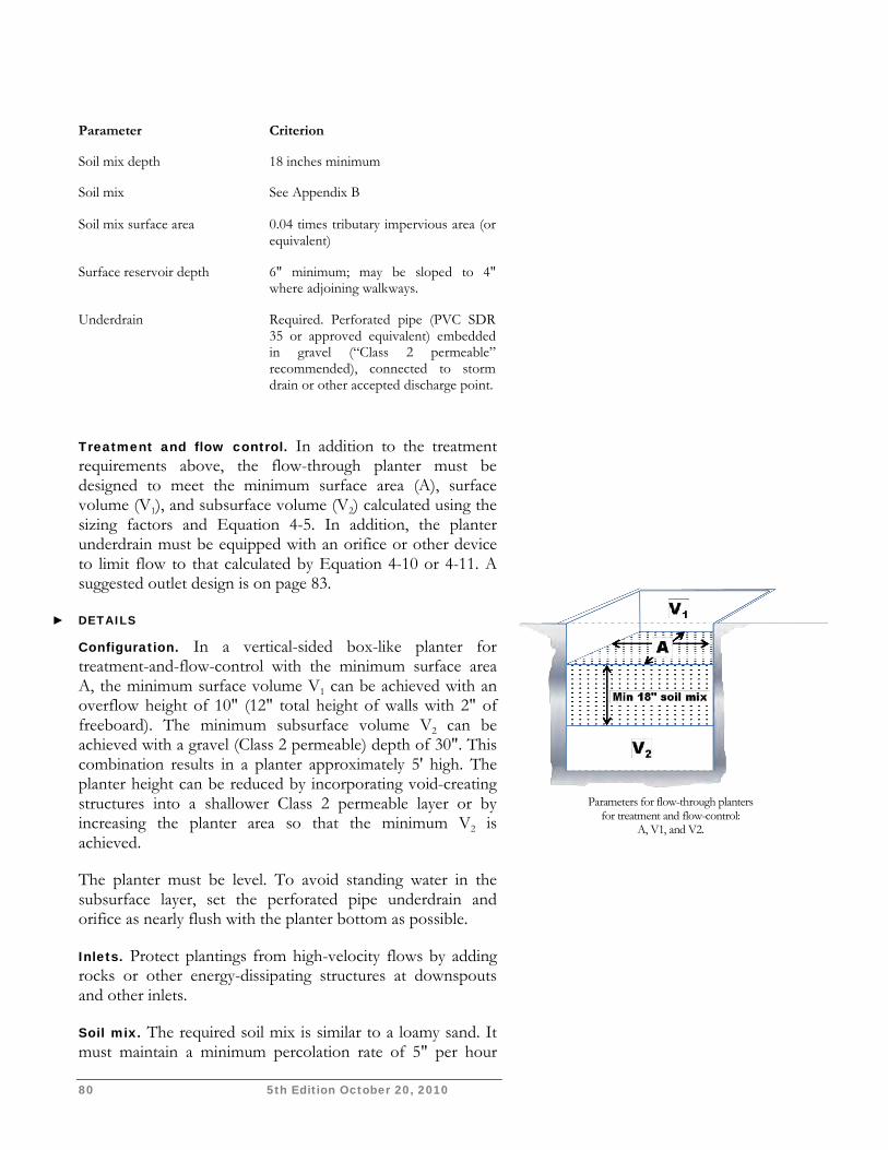
80 5th Edition October 20, 2010
Parameter Criterion
Soil mix depth 18 inches minimum
Soil mix See Appendix B
Soil mix surface area 0.04 times tributary impervious area (or equivalent)
Surface reservoir depth 6" minimum; may be sloped to 4" where adjoining walkways.
Underdrain Required. Perforated pipe (PVC SDR 35 or approved equivalent) embedded in gravel (“Class 2 permeable” recommended), connected to storm drain or other accepted discharge point.
Treatment and flow control. In addition to the treatment requirements above, the flow-through planter must be designed to meet the minimum surface area (A), surface volume (V1), and subsurface volume (V2) calculated using the sizing factors and Equation 4-5. In addition, the planter underdrain must be equipped with an orifice or other device to limit flow to that calculated by Equation 4-10 or 4-11. A suggested outlet design is on page 83.
► DETAILS
Configuration. In a vertical-sided box-like planter for treatment-and-flow-control with the minimum surface area A, the minimum surface volume V1 can be achieved with an overflow height of 10" (12" total height of walls with 2" of freeboard). The minimum subsurface volume V2 can be achieved with a gravel (Class 2 permeable) depth of 30". This combination results in a planter approximately 5' high. The planter height can be reduced by incorporating void-creating structures into a shallower Class 2 permeable layer or by increasing the planter area so that the minimum V2 is achieved.
The planter must be level. To avoid standing water in the subsurface layer, set the perforated pipe underdrain and orifice as nearly flush with the planter bottom as possible.
Inlets. Protect plantings from high-velocity flows by adding rocks or other energy-dissipating structures at downspouts and other inlets.
Soil mix. The required soil mix is similar to a loamy sand. It must maintain a minimum percolation rate of 5" per hour
Parameters for flow-through planters
for treatment and flow-control: A, V1, and V2.
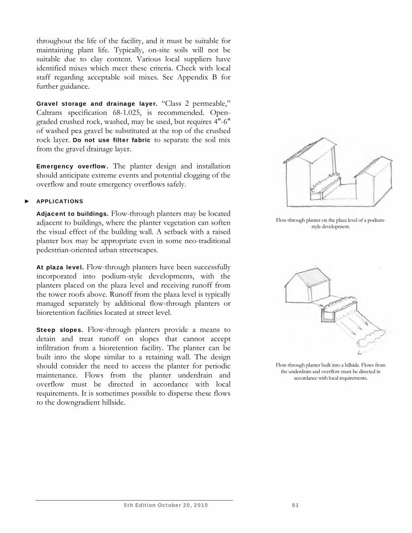
5th Edition October 20, 2010 81
throughout the life of the facility, and it must be suitable for maintaining plant life. Typically, on-site soils will not be suitable due to clay content. Various local suppliers have identified mixes which meet these criteria. Check with local staff regarding acceptable soil mixes. See Appendix B for further guidance.
Gravel storage and drainage layer. “Class 2 permeable,” Caltrans specification 68-1.025, is recommended. Open-graded crushed rock, washed, may be used, but requires 4"-6" of washed pea gravel be substituted at the top of the crushed rock layer. Do not use filter fabric to separate the soil mix from the gravel drainage layer.
Emergency overflow. The planter design and installation should anticipate extreme events and potential clogging of the overflow and route emergency overflows safely.
► APPLICATIONS
Adjacent to buildings. Flow-through planters may be located adjacent to buildings, where the planter vegetation can soften the visual effect of the building wall. A setback with a raised planter box may be appropriate even in some neo-traditional pedestrian-oriented urban streetscapes.
At plaza level. Flow-through planters have been successfully incorporated into podium-style developments, with the planters placed on the plaza level and receiving runoff from the tower roofs above. Runoff from the plaza level is typically managed separately by additional flow-through planters or bioretention facilities located at street level.
Steep slopes. Flow-through planters provide a means to detain and treat runoff on slopes that cannot accept infiltration from a bioretention facility. The planter can be built into the slope similar to a retaining wall. The design should consider the need to access the planter for periodic maintenance. Flows from the planter underdrain and overflow must be directed in accordance with local requirements. It is sometimes possible to disperse these flows to the downgradient hillside.
Flow-through planter built into a hillside. Flows from
the underdrain and overflow must be directed in accordance with local requirements.
Flow-through planter on the plaza level of a podium-
style development.
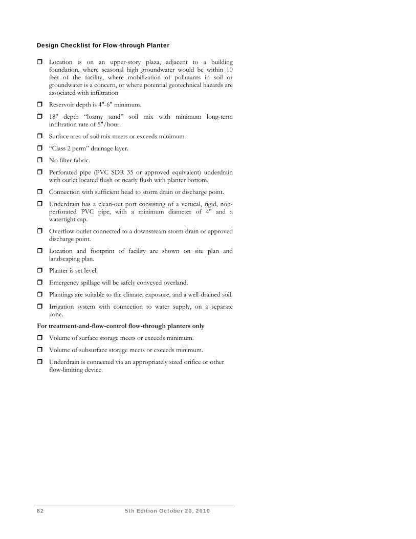
82 5th Edition October 20, 2010
Design Checklist for Flow-through Planter Location is on an upper-story plaza, adjacent to a building
foundation, where seasonal high groundwater would be within 10 feet of the facility, where mobilization of pollutants in soil or groundwater is a concern, or where potential geotechnical hazards are associated with infiltration
Reservoir depth is 4"-6" minimum.
18" depth “loamy sand” soil mix with minimum long-term infiltration rate of 5"/hour.
Surface area of soil mix meets or exceeds minimum.
“Class 2 perm” drainage layer.
No filter fabric.
Perforated pipe (PVC SDR 35 or approved equivalent) underdrain with outlet located flush or nearly flush with planter bottom.
Connection with sufficient head to storm drain or discharge point.
Underdrain has a clean-out port consisting of a vertical, rigid, non-perforated PVC pipe, with a minimum diameter of 4" and a watertight cap.
Overflow outlet connected to a downstream storm drain or approved discharge point.
Location and footprint of facility are shown on site plan and landscaping plan.
Planter is set level.
Emergency spillage will be safely conveyed overland.
Plantings are suitable to the climate, exposure, and a well-drained soil.
Irrigation system with connection to water supply, on a separate zone.
For treatment-and-flow-control flow-through planters only
Volume of surface storage meets or exceeds minimum.
Volume of subsurface storage meets or exceeds minimum.
Underdrain is connected via an appropriately sized orifice or other flow-limiting device.
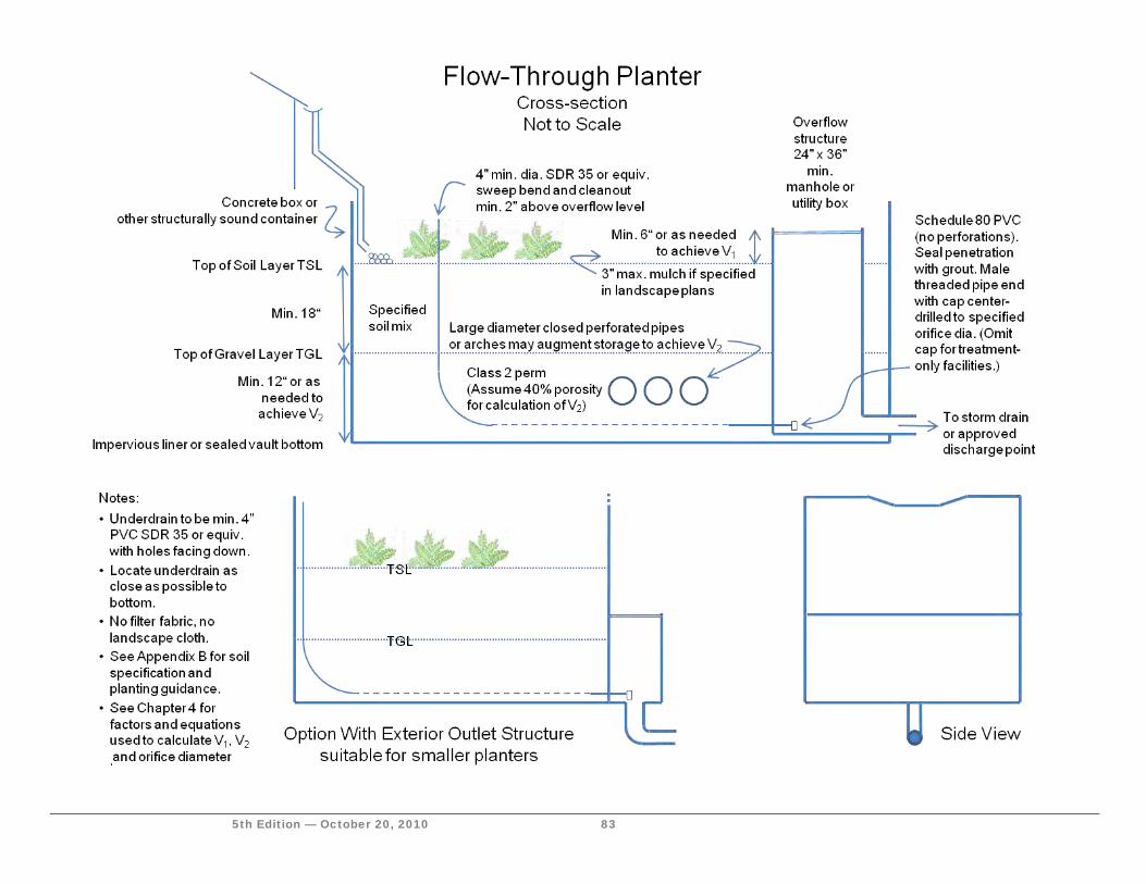
5th Edition — October 20, 2010 83

84 5th Edition October 20, 2010
This page intentionally left blank.
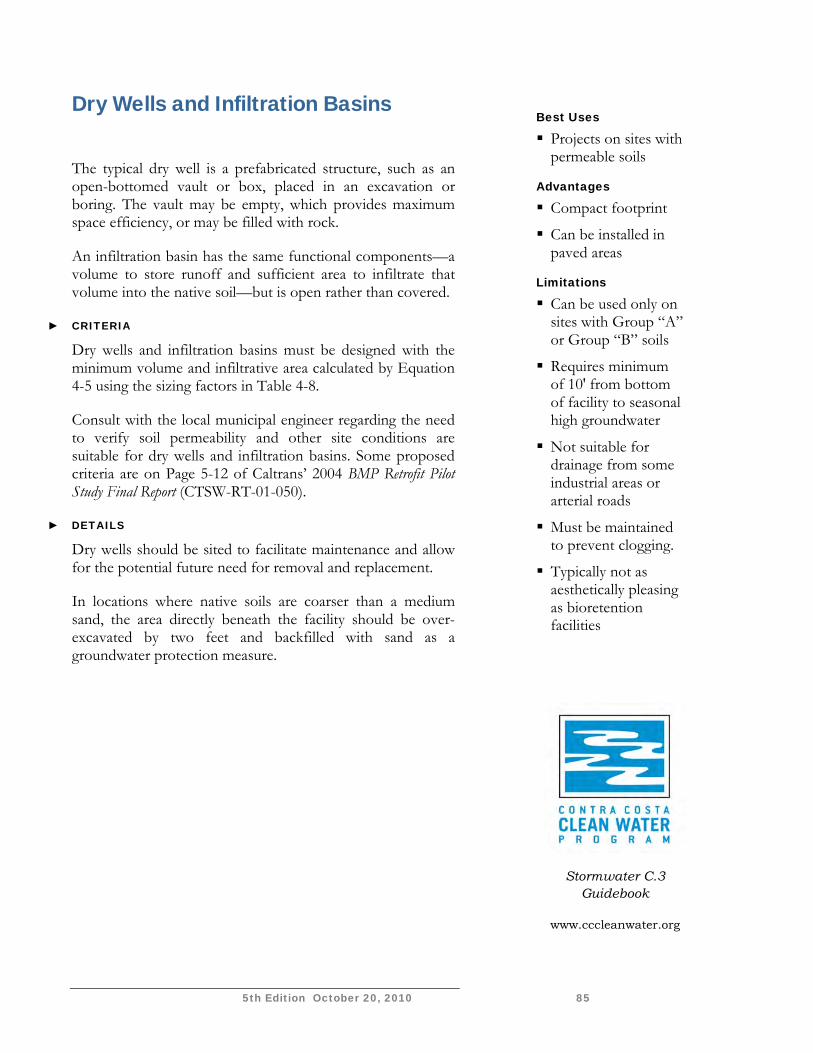
5th Edition October 20, 2010 85
Dry Wells and Infiltration Basins
The typical dry well is a prefabricated structure, such as an open-bottomed vault or box, placed in an excavation or boring. The vault may be empty, which provides maximum space efficiency, or may be filled with rock.
An infiltration basin has the same functional components—a volume to store runoff and sufficient area to infiltrate that volume into the native soil—but is open rather than covered.
► CRITERIA
Dry wells and infiltration basins must be designed with the minimum volume and infiltrative area calculated by Equation 4-5 using the sizing factors in Table 4-8.
Consult with the local municipal engineer regarding the need to verify soil permeability and other site conditions are suitable for dry wells and infiltration basins. Some proposed criteria are on Page 5-12 of Caltrans’ 2004 BMP Retrofit Pilot Study Final Report (CTSW-RT-01-050).
► DETAILS
Dry wells should be sited to facilitate maintenance and allow for the potential future need for removal and replacement.
In locations where native soils are coarser than a medium sand, the area directly beneath the facility should be over-excavated by two feet and backfilled with sand as a groundwater protection measure.
Best Uses
Projects on sites with permeable soils
Advantages
Compact footprint
Can be installed in paved areas
Limitations
Can be used only on sites with Group “A” or Group “B” soils
Requires minimum of 10' from bottom of facility to seasonal high groundwater
Not suitable for drainage from some industrial areas or arterial roads
Must be maintained to prevent clogging.
Typically not as aesthetically pleasing as bioretention facilities
Stormwater C.3 Guidebook
www.cccleanwater.org
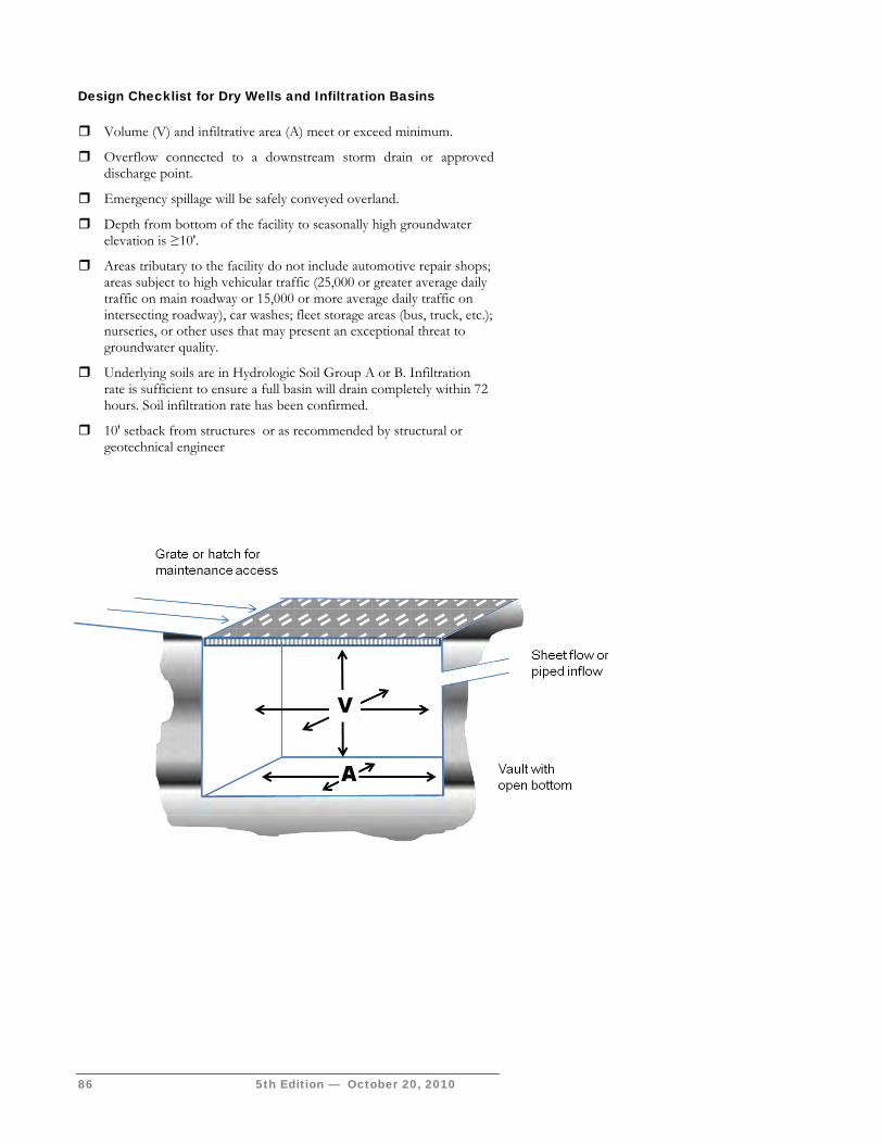
86 5th Edition — October 20, 2010
Design Checklist for Dry Wells and Infiltration Basins Volume (V) and infiltrative area (A) meet or exceed minimum.
Overflow connected to a downstream storm drain or approved discharge point.
Emergency spillage will be safely conveyed overland.
Depth from bottom of the facility to seasonally high groundwater elevation is ≥10'.
Areas tributary to the facility do not include automotive repair shops; areas subject to high vehicular traffic (25,000 or greater average daily traffic on main roadway or 15,000 or more average daily traffic on intersecting roadway), car washes; fleet storage areas (bus, truck, etc.); nurseries, or other uses that may present an exceptional threat to groundwater quality.
Underlying soils are in Hydrologic Soil Group A or B. Infiltration rate is sufficient to ensure a full basin will drain completely within 72 hours. Soil infiltration rate has been confirmed.
10' setback from structures or as recommended by structural or geotechnical engineer
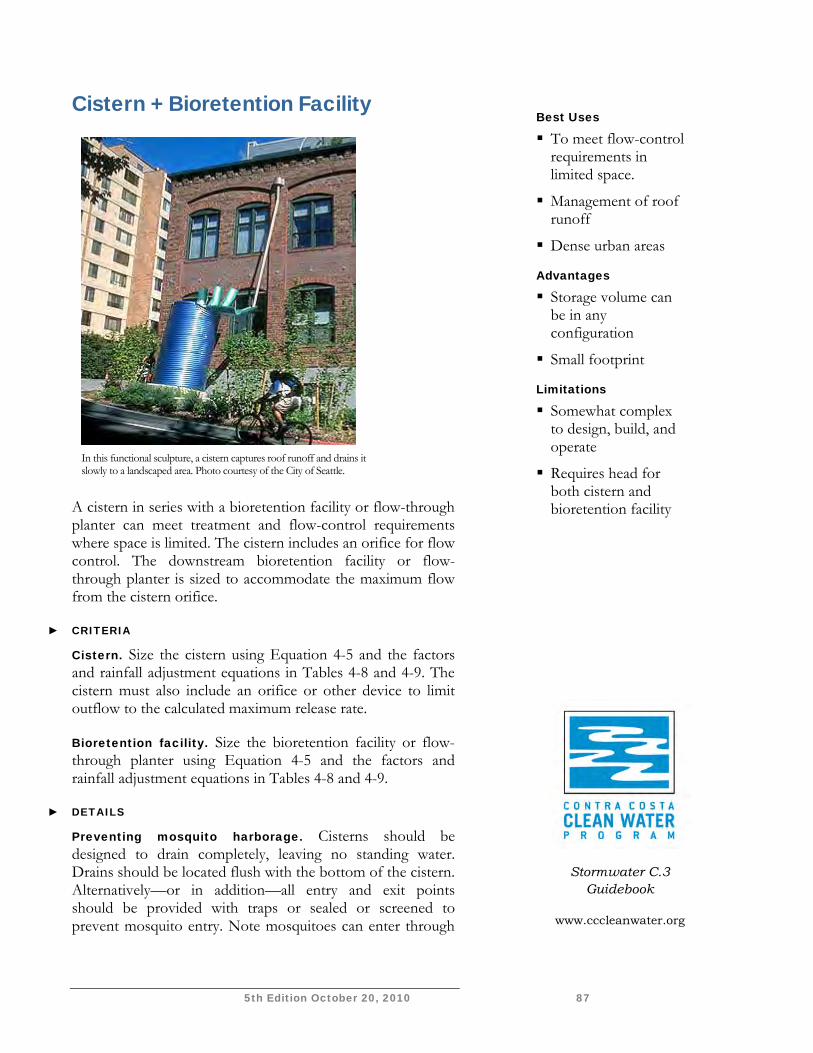
5th Edition October 20, 2010 87
Cistern + Bioretention Facility
A cistern in series with a bioretention facility or flow-through planter can meet treatment and flow-control requirements where space is limited. The cistern includes an orifice for flow control. The downstream bioretention facility or flow-through planter is sized to accommodate the maximum flow from the cistern orifice.
► CRITERIA
Cistern. Size the cistern using Equation 4-5 and the factors and rainfall adjustment equations in Tables 4-8 and 4-9. The cistern must also include an orifice or other device to limit outflow to the calculated maximum release rate.
Bioretention facility. Size the bioretention facility or flow-through planter using Equation 4-5 and the factors and rainfall adjustment equations in Tables 4-8 and 4-9.
► DETAILS
Preventing mosquito harborage. Cisterns should be designed to drain completely, leaving no standing water. Drains should be located flush with the bottom of the cistern. Alternatively—or in addition—all entry and exit points should be provided with traps or sealed or screened to prevent mosquito entry. Note mosquitoes can enter through
In this functional sculpture, a cistern captures roof runoff and drains it slowly to a landscaped area. Photo courtesy of the City of Seattle.
Best Uses
To meet flow-control requirements in limited space.
Management of roof runoff
Dense urban areas
Advantages
Storage volume can be in any configuration
Small footprint
Limitations
Somewhat complex to design, build, and operate
Requires head for both cistern and bioretention facility
Stormwater C.3 Guidebook
www.cccleanwater.org
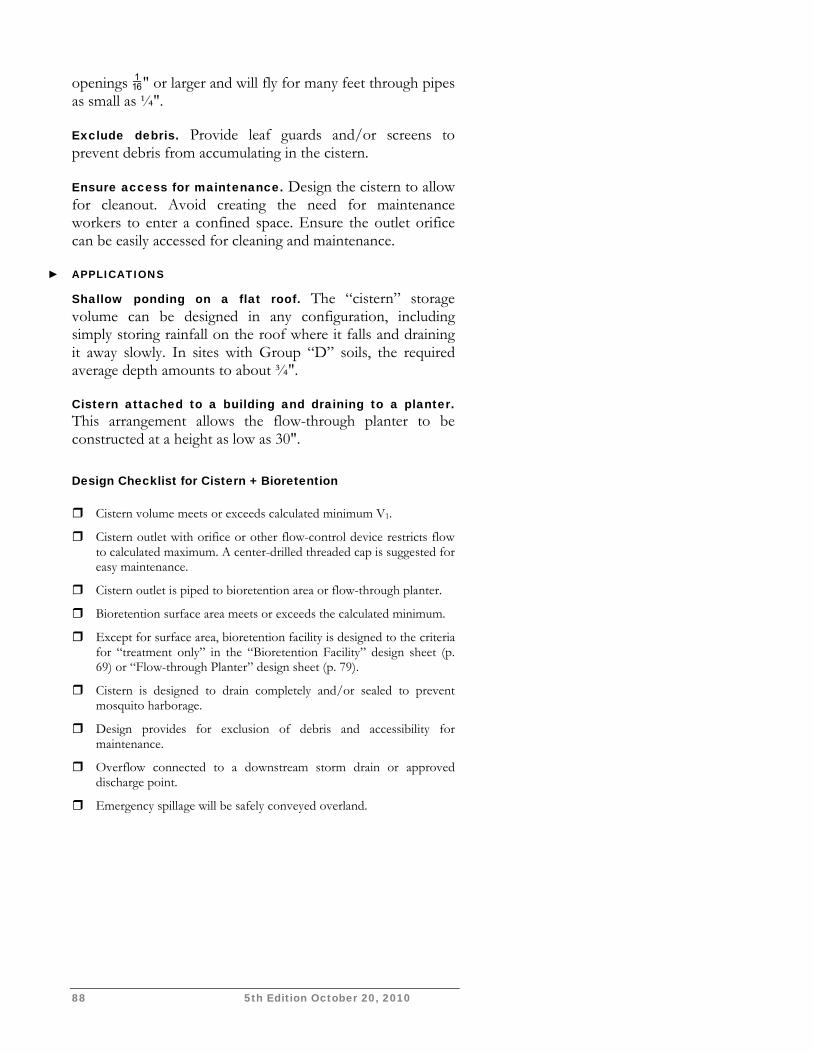
88 5th Edition October 20, 2010
openings " or larger and will fly for many feet through pipes as small as ¼".
Exclude debris. Provide leaf guards and/or screens to prevent debris from accumulating in the cistern.
Ensure access for maintenance. Design the cistern to allow for cleanout. Avoid creating the need for maintenance workers to enter a confined space. Ensure the outlet orifice can be easily accessed for cleaning and maintenance.
► APPLICATIONS
Shallow ponding on a flat roof. The “cistern” storage volume can be designed in any configuration, including simply storing rainfall on the roof where it falls and draining it away slowly. In sites with Group “D” soils, the required average depth amounts to about ¾".
Cistern attached to a building and draining to a planter. This arrangement allows the flow-through planter to be constructed at a height as low as 30".
Design Checklist for Cistern + Bioretention Cistern volume meets or exceeds calculated minimum V1.
Cistern outlet with orifice or other flow-control device restricts flow to calculated maximum. A center-drilled threaded cap is suggested for easy maintenance.
Cistern outlet is piped to bioretention area or flow-through planter.
Bioretention surface area meets or exceeds the calculated minimum.
Except for surface area, bioretention facility is designed to the criteria for “treatment only” in the “Bioretention Facility” design sheet (p. 69) or “Flow-through Planter” design sheet (p. 79).
Cistern is designed to drain completely and/or sealed to prevent mosquito harborage.
Design provides for exclusion of debris and accessibility for maintenance.
Overflow connected to a downstream storm drain or approved discharge point.
Emergency spillage will be safely conveyed overland.
5th Edition October 20, 2010 89
A
V

90 5th Edition October 20, 2010
This page intentionally left blank.
.
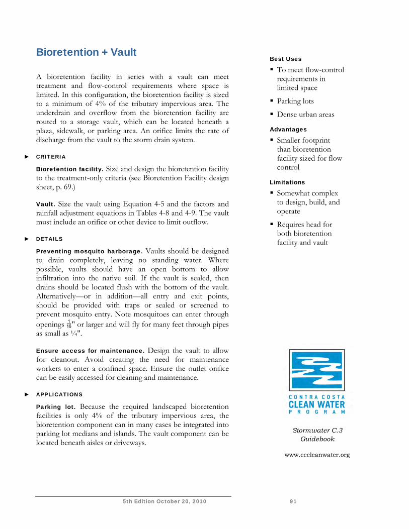
5th Edition October 20, 2010 91
Bioretention + Vault A bioretention facility in series with a vault can meet treatment and flow-control requirements where space is limited. In this configuration, the bioretention facility is sized to a minimum of 4% of the tributary impervious area. The underdrain and overflow from the bioretention facility are routed to a storage vault, which can be located beneath a plaza, sidewalk, or parking area. An orifice limits the rate of discharge from the vault to the storm drain system.
► CRITERIA
Bioretention facility. Size and design the bioretention facility to the treatment-only criteria (see Bioretention Facility design sheet, p. 69.)
Vault. Size the vault using Equation 4-5 and the factors and rainfall adjustment equations in Tables 4-8 and 4-9. The vault must include an orifice or other device to limit outflow.
► DETAILS
Preventing mosquito harborage. Vaults should be designed to drain completely, leaving no standing water. Where possible, vaults should have an open bottom to allow infiltration into the native soil. If the vault is sealed, then drains should be located flush with the bottom of the vault. Alternatively—or in addition—all entry and exit points, should be provided with traps or sealed or screened to prevent mosquito entry. Note mosquitoes can enter through openings " or larger and will fly for many feet through pipes as small as ¼".
Ensure access for maintenance. Design the vault to allow for cleanout. Avoid creating the need for maintenance workers to enter a confined space. Ensure the outlet orifice can be easily accessed for cleaning and maintenance.
► APPLICATIONS
Parking lot. Because the required landscaped bioretention facilities is only 4% of the tributary impervious area, the bioretention component can in many cases be integrated into parking lot medians and islands. The vault component can be located beneath aisles or driveways.
Best Uses
To meet flow-control requirements in limited space
Parking lots
Dense urban areas
Advantages
Smaller footprint than bioretention facility sized for flow control
Limitations
Somewhat complex to design, build, and operate
Requires head for both bioretention facility and vault
Stormwater C.3 Guidebook
www.cccleanwater.org
92 5th Edition October 20, 2010
Multiple bioretention facilities draining to a single vault. Two or more bioretention areas can be connected to a single vault. The vault minimum volume and outlet maximum flow rate are the sum of those calculated for each individual bioretention facility.
Vault with pumped discharge. Where insufficient head exists, vaults may be equipped with pumps to discharge (at a rate no greater than the calculated maximum) to a storm drain or approved discharge point.
Design Checklist for Bioretention + Vault Bioretention facility is designed to the treatment-only criteria in the
“Bioretention Facility” design sheet (pp. 69-78).
Vault volume meets or exceeds calculated minimum.
Vault outlet with orifice or other flow-control device restricts flow to calculated maximum.
Bioretention facility underdrain is routed to the vault.
Bioretention facility overflow is routed to the vault.
Sufficient head exists to convey flow from the underdrain to the vault and from the vault to the discharge point.
Vault is designed to drain completely and/or sealed to prevent mosquito harborage.
Vault design provides for exclusion of debris and accessibility for maintenance.
Vault outlet and overflow are connected to a downstream storm drain or approved discharge point.
Emergency spillage will be safely conveyed overland.
S T O R M W A T E R C . 3 . C O M P L I A N C E
5th Edition — October 20, 2010 93
Construction of Integrated Management Practices Guidance for preparing construction documents and overseeing construction of Integrated Management Practices
etails of construction are critical to ensuring stormwater facilities work properly. A misplaced inlet, an overflow at the wrong elevation, or the wrong soil mix can make a bioretention facility useless or ineffective even
before it comes on-line, and could result in delays to project approvals and additional expense.
Your Stormwater Control Plan must contain enough detail to demonstrate your planned LID features and facilities are feasible and are coordinated with the project site plan, architectural renderings, landscape design, and other information submitted with your application for development approvals. Additional detail must be shown on plans submitted with applications for building and grading permits. During construction, municipal inspectors will check the work against the approved plans.
The Design Sheets in Chapter 4 include details, many of which are critical to proper functioning of the IMP. This chapter describes specific items to be
checked during review of construction documents and during construction.
LID features and facilities have been routinely incorporated into development projects for only a few years. The community of land development professionals and municipal staff continue to compile and analyze “lessons learned” from their experience.
The following guidance is based on those lessons.
Chapter
5
D
I C O N K E Y
Helpful Tip
Submittal Requirement
Terms to Look Up
References & Resources
C O N T R A C O S T A C L E A N W A T E R P R O G R A M
94 5th Edition — October 20, 2010
What to Show on Construction Plans With few exceptions, the plan set should include separate sheets specifically incorporating the features and facilities described in the Stormwater Control Plan. The information on these sheets must be carefully coordinated and made consistent with grading plans, utility plans, landscaping plans, and (in many cases) architectural plans. Consider including the grading plan (screened) as background for the stormwater sheets. It may also be appropriate to show portions of the roofing plan wherever roof ridges define Drainage Management Areas (DMAs).
► GRADING IS KEY
Municipal staff will typically require plans showing the outline of each bioretention facility or other IMP, along with the delineation of DMAs. Call out elevations, including the following:
At curb cut inlets, show elevations for top of paving, top of curb, and top of the bioretention soil layer.
At overflow grates, show the grate elevation and the adjacent top of soil elevation.
Call out elevations of piped inlets.
Show how DMAs follow grade breaks, consistent with the grading plan and the Stormwater Control Plan.
For treatment-and-flow-control IMPs, demonstrate how the minimum surface volume V1 is attained by the design.
► SHOW HOW RUNOFF MOVES
As needed for clarity, show the direction of runoff flow across roofs and pavement and into IMPs. For runoff conveyed via pipes or channels, show locations, slopes, and elevations at the beginning and end of each run.
For roof drainage, show the routing of roof leaders. Use drawings or notes to make clear how drainage from leaders is routed under walkways, across pavement, through drainage pipes, or by other means to reach the IMP.
Show pipes or channels connecting the IMP underdrain and overflow to the site drainage system, municipal storm drain system, or other approved discharge point. Call out slopes and key elevations.
Design Note Avoid creating bioretention areas that are deeper than necessary, and avoid
having landscaped slopes draining on to the top of bioretention soil. Use surface drainage, such as valley gutters or trench
drains, to keep drainage within a few inches below top of pavement. Or use a “bubble up” to bring drainage back up
closer to the surface.
C H A P T E R 5 : C O N S T R U C T I O N
5th Edition—October 20, 2010 95
► SHOW IMPS IN CROSS-SECTION
Use one or more cross-section drawings to illustrate details and key IMP elevations, including bottom of excavation, top of gravel layer, top of soil layer, edge treatments, inlet elevations, overflow grate elevations, rim elevations, locations of rock for energy dissipation, moisture barriers, and other information. Call out specifications or refer to specifications elsewhere for gravel (Class 2 perm) and soil mix.
Show the arrangement and details of outlet structures, particularly for treatment-plus-flow-control IMPs. The details in the Chapter 4 design sheets for bioretention and flow-through planters may be used as a general guide.
Items to Be Inspected During Construction Successful construction of IMPs requires attention to detail during every stage of the construction process, from initial layout to rough grading, installation of utilities, construction of buildings, paving, landscaping, and final clean-up and inspection.
Construction project managers need to understand the purpose and function of IMPs and know how to avoid common missteps that can occur during construction. For bioretention facilities, the following operating principles should be noted at a pre-construction meeting.
Runoff flow from the intended tributary drainage management area must flow into the facility.
The surface reservoir must fill to its intended volume during high inflows.
Runoff must filter rapidly through the layer of imported soil mix.
Filtered runoff must infiltrate into the native soil to the extent possible (or allowable).
Remaining runoff must be captured and drained to a storm drain or other approved location.
See the model construction inspection checklist on the following pages.
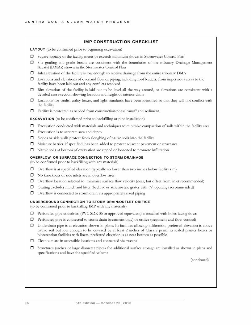
C O N T R A C O S T A C L E A N W A T E R P R O G R A M
96 5th Edition — October 20, 2010
IMP CONSTRUCTION CHECKLIST
LAYOUT (to be confirmed prior to beginning excavation)
Square footage of the facility meets or exceeds minimum shown in Stormwater Control Plan Site grading and grade breaks are consistent with the boundaries of the tributary Drainage Management
Area(s) (DMAs) shown in the Stormwater Control Plan Inlet elevation of the facility is low enough to receive drainage from the entire tributary DMA Locations and elevations of overland flow or piping, including roof leaders, from impervious areas to the
facility have been laid out and any conflicts resolved Rim elevation of the facility is laid out to be level all the way around, or elevations are consistent with a
detailed cross-section showing location and height of interior dams Locations for vaults, utility boxes, and light standards have been identified so that they will not conflict with
the facility Facility is protected as needed from construction-phase runoff and sediment
EXCAVATION (to be confirmed prior to backfilling or pipe installation)
Excavation conducted with materials and techniques to minimize compaction of soils within the facility area Excavation is to accurate area and depth Slopes or side walls protect from sloughing of native soils into the facility Moisture barrier, if specified, has been added to protect adjacent pavement or structures. Native soils at bottom of excavation are ripped or loosened to promote infiltration
OVERFLOW OR SURFACE CONNECTION TO STORM DRAINAGE (to be confirmed prior to backfilling with any materials)
Overflow is at specified elevation (typically no lower than two inches below facility rim) No knockouts or side inlets are in overflow riser Overflow location selected to minimize surface flow velocity (near, but offset from, inlet recommended) Grating excludes mulch and litter (beehive or atrium-style grates with ¼" openings recommended) Overflow is connected to storm drain via appropriately sized piping
UNDERGROUND CONNECTION TO STORM DRAIN/OUTLET ORIFICE (to be confirmed prior to backfilling IMP with any materials)
Perforated pipe undedrain (PVC SDR 35 or approved equivalent) is installed with holes facing down Perforated pipe is connected to storm drain (treatment only) or orifice (treatment-and-flow-control) Underdrain pipe is at elevation shown in plans. In facilities allowing infiltration, preferred elevation is above
native soil but low enough to be covered by at least 2 inches of Class 2 perm; in sealed planter boxes or bioretention facilities with liners, preferred elevation is as near bottom as possible
Cleanouts are in accessible locations and connected via sweeps
Structures (arches or large diameter pipes) for additional surface storage are installed as shown in plans and specifications and have the specified volume
(continued)
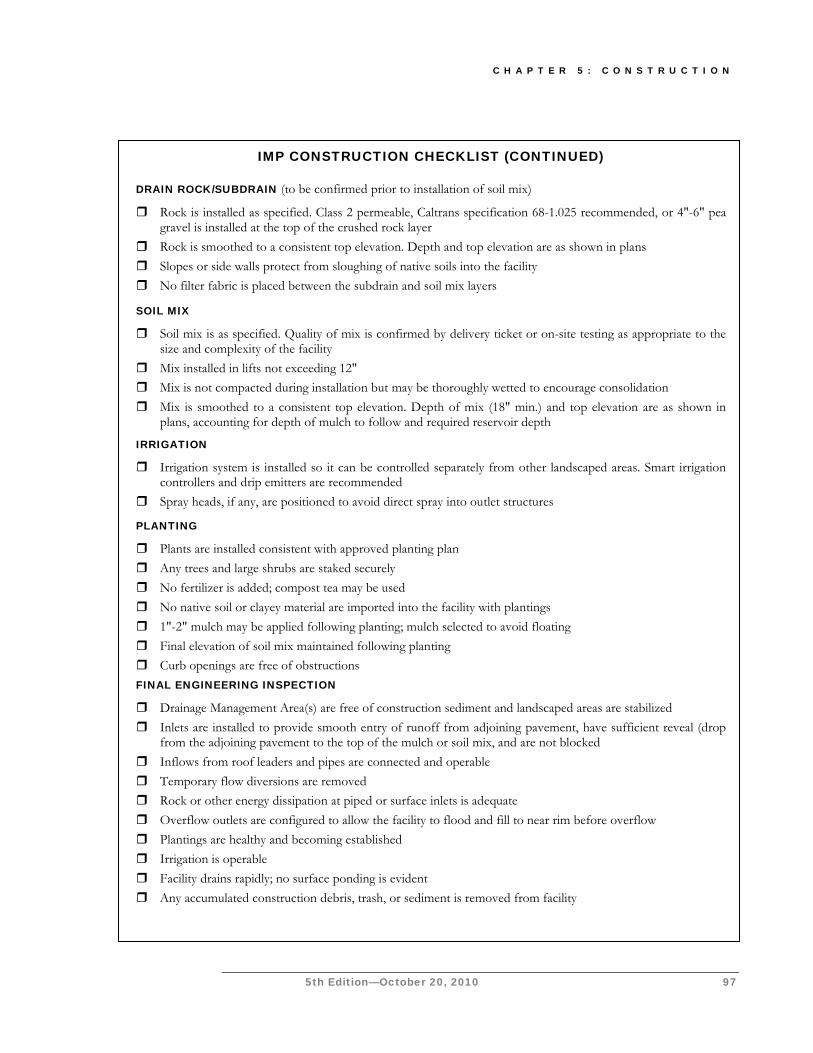
C H A P T E R 5 : C O N S T R U C T I O N
5th Edition—October 20, 2010 97
IMP CONSTRUCTION CHECKLIST (CONTINUED)
DRAIN ROCK/SUBDRAIN (to be confirmed prior to installation of soil mix)
Rock is installed as specified. Class 2 permeable, Caltrans specification 68-1.025 recommended, or 4"-6" pea gravel is installed at the top of the crushed rock layer
Rock is smoothed to a consistent top elevation. Depth and top elevation are as shown in plans Slopes or side walls protect from sloughing of native soils into the facility No filter fabric is placed between the subdrain and soil mix layers
SOIL MIX
Soil mix is as specified. Quality of mix is confirmed by delivery ticket or on-site testing as appropriate to the size and complexity of the facility
Mix installed in lifts not exceeding 12" Mix is not compacted during installation but may be thoroughly wetted to encourage consolidation Mix is smoothed to a consistent top elevation. Depth of mix (18" min.) and top elevation are as shown in
plans, accounting for depth of mulch to follow and required reservoir depth
IRRIGATION
Irrigation system is installed so it can be controlled separately from other landscaped areas. Smart irrigation controllers and drip emitters are recommended
Spray heads, if any, are positioned to avoid direct spray into outlet structures
PLANTING
Plants are installed consistent with approved planting plan Any trees and large shrubs are staked securely No fertilizer is added; compost tea may be used No native soil or clayey material are imported into the facility with plantings 1"-2" mulch may be applied following planting; mulch selected to avoid floating Final elevation of soil mix maintained following planting Curb openings are free of obstructions FINAL ENGINEERING INSPECTION
Drainage Management Area(s) are free of construction sediment and landscaped areas are stabilized Inlets are installed to provide smooth entry of runoff from adjoining pavement, have sufficient reveal (drop
from the adjoining pavement to the top of the mulch or soil mix, and are not blocked Inflows from roof leaders and pipes are connected and operable Temporary flow diversions are removed Rock or other energy dissipation at piped or surface inlets is adequate Overflow outlets are configured to allow the facility to flood and fill to near rim before overflow Plantings are healthy and becoming established Irrigation is operable Facility drains rapidly; no surface ponding is evident Any accumulated construction debris, trash, or sediment is removed from facility

S T O R M W A T E R C . 3 . C O M P L I A N C E
5th Edition — October 20, 2010 99
Operation & Maintenance of Stormwater Facilities How to prepare a customized Stormwater Facilities Operation & Maintenance Plan for the treatment BMPs on your site.
tormwater NPDES Permit Provision C.3.e requires each municipality verify stormwater treatment and flow-control facilities are adequately maintained. Municipalities must report the results of inspections to the Water Boards
annually.
Facilities you install as part of your project will be incorporated into the local municipality’s verification program. This is a six-stage process:
1. Determine who will own the facility and be responsible for its maintenance in perpetuity and document this in your Stormwater Control Plan. The Stormwater Control Plan must also identify the means by which ongoing maintenance will be assured (for example, a maintenance agreement that runs with the land).
2. Identify typical maintenance requirements, allow for these requirements in your project planning and preliminary design, and document the typical maintenance requirements in your Stormwater Control Plan.
3. Prepare an Operation and Maintenance Plan (O&M Plan) for the site incorporating detailed requirements for each treatment and flow-control facility. Typically, a draft O&M Plan must be submitted with the building permit application, and a final O&M Plan must be submitted for review and approved by the municipality prior to building permit final and issuance of a certificate of occupancy. Local requirements vary as to schedule. Check with municipal staff.
Chapter
6
S
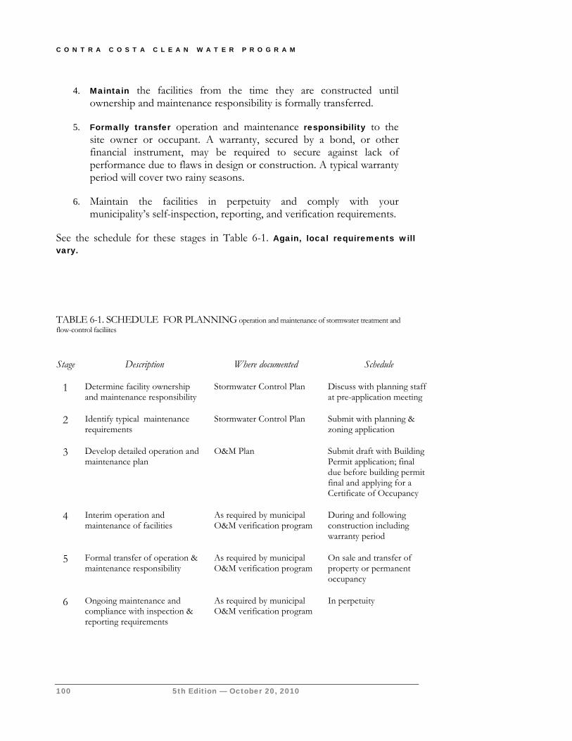
C O N T R A C O S T A C L E A N W A T E R P R O G R A M
100 5th Edition — October 20, 2010
4. Maintain the facilities from the time they are constructed until ownership and maintenance responsibility is formally transferred.
5. Formally transfer operation and maintenance responsibility to the site owner or occupant. A warranty, secured by a bond, or other financial instrument, may be required to secure against lack of performance due to flaws in design or construction. A typical warranty period will cover two rainy seasons.
6. Maintain the facilities in perpetuity and comply with your municipality’s self-inspection, reporting, and verification requirements.
See the schedule for these stages in Table 6-1. Again, local requirements will vary.
TABLE 6-1. SCHEDULE FOR PLANNING operation and maintenance of stormwater treatment and flow-control faciliites
Stage Description Where documented Schedule
1 Determine facility ownership and maintenance responsibility
Stormwater Control Plan Discuss with planning staff at pre-application meeting
2 Identify typical maintenance requirements
Stormwater Control Plan Submit with planning & zoning application
3 Develop detailed operation and maintenance plan
O&M Plan Submit draft with Building Permit application; final due before building permit final and applying for a Certificate of Occupancy
4 Interim operation and maintenance of facilities
As required by municipal O&M verification program
During and following construction including warranty period
5 Formal transfer of operation & maintenance responsibility
As required by municipal O&M verification program
On sale and transfer of property or permanent occupancy
6 Ongoing maintenance and compliance with inspection & reporting requirements
As required by municipal O&M verification program
In perpetuity
C H A P T E R 6 : S T O R M W A T E R F A C I L I T Y M A I N T E N A N C E
5th Edition—October 20, 2010 101
Stage 1: Ownership and Responsibility Your Stormwater Control Plan must specify a means to finance and implement maintenance of treatment and flow-control facilities in perpetuity.
Depending on the intended use of your site and the policies of the local municipality, this may require one or more of the following:
Execution of a maintenance agreement that “runs with the land.”
Creation of a homeowners association (HOA) and execution of an agreement by the HOA to maintain the facilities as well as an annual inspection fee.
Formation of a new community facilities district or other special district, or addition of the properties to an existing special district.
Dedication of fee title or easement transferring ownership of the facility (and the land under it) to the municipality.
Ownership and maintenance responsibility for treatment and flow-control facilities should be discussed at the beginning of project planning, typically at the pre-application meeting for planning and zoning review. Experience has shown provisions to finance and implement maintenance of treatment and flow-control facilities can be a major stumbling block to project approval, particularly for small residential subdivisions. (See “Applying C.3 to New Subdivisions” in Chapter 1.)
► PRIVATE OWNERSHIP AND MAINTENANCE
The municipality may require—as a condition of project approval—that a maintenance agreement be executed.
The CCCWP has prepared the following model agreements:
Operation and Maintenance Agreement for a Single Parcel with a Stormwater Management Facility
Operation and Maintenance Agreement for Subdivisions with Stormwater Management Facilities
Operation and Maintenance Agreement for Subdivisions with Stormwater Management Facilities and a Homeowners Association
CC&R and Subdivision Map Provisions for Subdivisions with Stormwater Management Facilities
C O N T R A C O S T A C L E A N W A T E R P R O G R A M
102 5th Edition — October 20, 2010
CC&R Provisions for Subdivisions with Stormwater Management Facilities and a Homeowners Association
The model agreements “run with the land,” so the agreement executed by a developer is binding on the owners of the subdivided lots. The agreement must be recorded prior to conveyance of the subdivided property.
The model agreements provide the municipality may collect a management and/or inspection fee established by the standard fee schedule. In addition, the agreements provide that, if the property owner fails to maintain the stormwater facility, the municipality may enter the property, restore the stormwater facility to good working order and obtain reimbursement,
including administrative costs, from the property owner.
To augment and enforce maintenance requirements, the County established a two-tiered Community Facilities District (Mello-Roos) throughout the unincorporated area to cover the costs of inspections, reporting to the Water Board and, if necessary, code enforcement and maintenance and repair of individual facilities. Some cities and towns may have similar districts.
► TRANSFER TO PUBLIC OWNERSHIP
Municipalities may sometimes choose to have a treatment and flow-control facility deeded to the public in fee or as an easement and maintain the facility as part of the municipal storm drain system. The municipality may recoup the costs of maintenance through a special tax, assessment district, or similar mechanism.
Locating an IMP in a public right-of-way or easement creates an additional design constraint—along with hydraulic grade, aesthetics, landscaping, and circulation. However, because sites typically drain to the street, it may be possible to locate a bioretention swale parallel with the edge of the parcel. The facility may complement, or substitute for, an underground storm drain system.
Even if the facility is to be deeded or transferred to the municipality after construction is complete, it is still the responsibility of the builder to identify general operation and maintenance requirements, prepare a detailed operation and maintenance plan, and to maintain the facility until that responsibility is formally transferred.
I C O N K E Y
Helpful Tip
Submittal Requirement
Terms to Look Up
References & Resources
Local Requirements
Cities, towns, or the County may have requirements that differ from,
or are in addition to, this countywide Guidebook. See Appendix A
and check with local planning and community development staff.
C H A P T E R 6 : S T O R M W A T E R F A C I L I T Y M A I N T E N A N C E
5th Edition—October 20, 2010 103
Stage 2: General Maintenance Requirements Include in your Stormwater Control Plan a general description of anticipated facility maintenance requirements. This will help ensure that:
Ongoing costs of maintenance have been considered in your facility selection and design.
Site and landscaping plans provide for access for inspections and by maintenance equipment.
Landscaping plans incorporate irrigation requirements for facility plantings.
Initial maintenance and replacement of facility plantings is incorporated into landscaping contracts and guarantees.
Fact sheets available on the CCCWP C.3 web page describe general maintenance requirements for the types of stormwater facilities featured in the LID Design Guide (Chapter 4). You can use this information to specify general maintenance requirements in your Stormwater Control Plan.
Maintenance fact sheets for conventional stormwater facilities are available in the California Stormwater BMP Handbooks.
Stage 3: Stormwater Facilities O&M Plan Submit a draft O&M Plan with construction documents when you apply for permits to begin grading or construction on the site. Revise your draft O&M plan in response to any comments from your municipality, and incorporate new information and changes developed during project construction. Submit a revised, final O&M plan before construction is complete.
Your Final Stormwater Control O&M Plan must be submitted to and approved by your municipality before your building permit can be made final and a certificate of occupancy issued.
Your O&M Plan must be kept on-site for use by maintenance personnel and during site inspections. It is also recommended that a copy of the Stormwater Control Plan be kept onsite as a reference.
Municipal Regional Permit Provision C.3.h requires Contra Costa municipalities periodically verify operation and maintenance (O&M) of facilities installed in their jurisdiction. Each year, they must report to the Water Board the facilities inspected that year and the status of each.
C O N T R A C O S T A C L E A N W A T E R P R O G R A M
104 5th Edition — October 20, 2010
The final O&M plan should incorporate solutions to any problems noted or changes that occurred during construction. For this reason, the final O&M plan may be submitted at the end of the construction period, before the application for final building permit and Certificate of Occupancy.
► TOOLS AND ASSISTANCE
The following step-by-step instructions—and forms available on the CCCWP website—will help you prepare your Stormwater Control Operation and Maintenance Plan. You may use, adapt, and assemble these documents to prepare your own Plan, which will be customized to the specific needs of your site.
These include:
A form for stating or updating key contact information.
An example Inspection and Maintenance Log.
A format for an independent inspector’s annual inspection report.
An example maintenance matrix including necessary maintenance activities, recommended frequency of inspections of maintenance, and indications that maintenance is necessary.
Additional useful references, including links to additional documents, are available in “References and Resources” at the end of this chapter.
► YOUR O&M PLAN: STEP BY STEP
The following step-by-step guidance will help you prepare each required section of your Stormwater Control Operation and Maintenance Plan.
Preparation of the plan will require familiarity with your stormwater facilities as they have been constructed and a fair amount of “thinking through” plans for their operation and maintenance. The text and forms provided here will assist you, but are no substitute for thoughtful planning.
► STEP 1: DESIGNATE RESPONSIBLE INDIVIDUALS
To begin creating your O&M Plan, your organization must designate and identify:
The individual who will have direct responsibility for the maintenance of stormwater controls. This individual should be the designated contact with municipal inspectors and should sign self-inspection reports and any correspondence with the municipality regarding verification inspections.
C H A P T E R 6 : S T O R M W A T E R F A C I L I T Y M A I N T E N A N C E
5th Edition—October 20, 2010 105
Employees or contractors who will report to the designated contact and are responsible for carrying out BMP operation and maintenance.
The corporate officer authorized to negotiate and execute any contracts that might be necessary for future changes to operation and maintenance or to implement remedial measures if problems occur.
Your designated respondent to problems, such as clogged drains or broken irrigation mains, that would require immediate response should they occur during off-hours.
It is recommended to use the form available on the CCCWP website to list this information. Updated contact information must be provided to the municipality immediately whenever a property is sold and whenever designated individuals or contractors change. Complete a new form—and mail or fax a copy to the municipality—whenever this occurs.
Draw or sketch an organization chart to show the relationships of authority and responsibility between the individuals responsible for O&M. This need not be elaborate, particularly for smaller organizations.
Describe how funding for BMP operation and maintenance will be assured, including sources of funds, budget category for expenditures, process for establishing the annual maintenance budget, and process for obtaining authority should unexpected expenditures for major corrective maintenance be required.
Describe how your organization will accommodate initial training of staff or contractors regarding the purpose, mode of operation, and maintenance requirements for the stormwater facilities on your site. Also, describe how your organization will ensure ongoing training as needed and in response to staff changes.
► STEP 2: SUMMARIZE DRAINAGE AND BMPS
Incorporate the following information from your Stormwater Control Plan into your O&M Plan:
Figures delineating and designating pervious and impervious areas.
Figures showing locations of stormwater facilities on the site.
Tables of pervious and impervious areas served by each facility.
Review the Stormwater Control Plan narrative that describes each facility and its tributary drainage area and update the text to incorporate any changes that may have occurred during planning and zoning review, building permit review, or construction. Incorporate the updated text into your O&M Plan.
C O N T R A C O S T A C L E A N W A T E R P R O G R A M
106 5th Edition — October 20, 2010
► STEP 3: DOCUMENT FACILITIES “AS BUILT”
Include the following information from final construction drawings:
Plans, elevations, and details of all facilities. Annotate if necessary with designations used in the Stormwater Control Plan.
Design information or calculations submitted in the detailed design phase (i.e., not included in the Stormwater Control Plan)
Specifications of construction for facilities, including sand or soil, compaction, pipe materials and bedding.
In the final O&M Plan, incorporate field changes to design drawings, including changes to any of the following:
Location and layouts of inflow piping, flow splitter boxes, and piping to off-site discharge
Depths and layering of soil, sand, or gravel
Placement of filter fabric or geotextiles (not recommended between soil and gravel layers of bioretention facilities)
Changes or substitutions in soil or other materials.
Natural soils encountered (e.g. sand or clay lenses)
► STEP 4: PREPARE CUSTOMIZED MAINTENANCE PLANS
Prepare a maintenance plan, schedule, and inspection checklists (routine, annual, and after major storms) for each facility. Plans and schedules for two or more similar facilities on the same site may be combined.
Use the following resources to prepare your customized maintenance plan, schedule, and checklists.
Specific information noted in Steps 2 and 3, above.
Other input from the facility designer, municipal staff, or other sources.
BMP Operation and Maintenance Fact Sheets (available on the CCCWP C.3 web page).
Note any particular characteristics or circumstances that could require attention in the future, and include any troubleshooting advice.
C H A P T E R 6 : S T O R M W A T E R F A C I L I T Y M A I N T E N A N C E
5th Edition—October 20, 2010 107
Also include manufacturer’s data, operating manuals, and maintenance requirements for any:
Pumps or other mechanical equipment.
Proprietary devices used as or in conjunction with BMPs.
Manufacturers’ publications should be referenced in the text (including models and serial numbers where available). Copies of the manufacturers’ publications should be included as an attachment in the back of your O&M Plan or as a separate document.
To better organize your maintenance plan, consider using the “O&M Maintenance Matrix” available on the Program’s C.3 web page to present inspection frequencies, observations, and appropriate maintenance response.
► STEP 5: COMPILE O&M PLAN
Your O&M Plan should follow this general outline:
I. Inspection and Maintenance Log
II. Updates, Revisions and Errata
III. Introduction
A. Narrative overview describing the site; drainage areas, routing, and discharge points; and treatment and flow control facilities
IV. Responsibility for Maintenance
A. General
(1) Name and contact information for responsible individual(s).
(2) Organization chart or charts showing organization of the maintenance function and location within the overall organization.
(3) Reference to Operation and Maintenance Agreement (if any). A copy of the agreement should be attached.
(4) Maintenance Funding
(a) Sources of funds for maintenance
(b) Budget category or line item
C O N T R A C O S T A C L E A N W A T E R P R O G R A M
108 5th Edition — October 20, 2010
(c) Description of procedure and process for ensuring adequate funding for maintenance
B. Staff Training Program
C. Records
D. Safety
V. Summary of Drainage Areas and Stormwater Facilities
A. Drainage Areas
(1) Drawings showing pervious and impervious areas (copied or adapted from Stormwater Control Plan)
(2) Designation and description of each drainage area and how flow is routed to the corresponding facility.
B. Treatment and Flow Control Facilities
(1) Drawings showing location and type of each facility
(2) General description of each facility (Consider a table if more than two facilities)
(a) Area drained and routing of discharge.
(b) Facility type and size
VI. BMP Design Documentation
A. “As-built” drawings of each facility (design drawings in the draft Plan)
B. Manufacturer’s data, manuals, and maintenance requirements for pumps, mechanical or electrical equipment, and proprietary facilities (include a “placeholder” in the draft plan for information not yet available).
C. Specific operation and maintenance concerns and troubleshooting
VII. Maintenance Schedule or Matrix
A. Maintenance Schedule for each facility with specific requirements for:
(1) Routine inspection and maintenance
C H A P T E R 6 : S T O R M W A T E R F A C I L I T Y M A I N T E N A N C E
5th Edition—October 20, 2010 109
(2) Annual inspection and maintenance
(3) Inspection and maintenance after major storms
B. Service Agreement Information
Assemble and make copies of your O&M Plan. One or more copies must be submitted to the municipality, and at least one copy kept on-site. Here are some suggestions for formatting the O&M Plan:
Format plans to 8½" x 11" to facilitate duplication, filing, and handling.
Include the revision date in the footer on each page.
Scan graphics and incorporate with text into a single electronic file. Keep the electronic file backed-up so that copies of the O&M Plan can be made if the hard copy is lost or damaged.
► STEP 6: UPDATES
Your Stormwater Control Operation and Maintenance Plan will be a living document.
Operation and maintenance personnel may change; mechanical equipment may be replaced, and additional maintenance procedures may be needed. Throughout these changes, the O&M Plan must be kept up-to-date.
Updates may be transmitted to your municipality at any time. However, at a minimum, updates to the O&M Plan must accompany the annual inspection report. These updates should reference the sections of the Plan being changed and should be placed in reverse chronological order (most recent at the top) in Section II of the binder. If the entire O&M Plan is updated, as it should be from time to time, these updates should be removed from the first section, but may be filed (perhaps in the back of the binder) for possible future reference.
Stage 4: Interim Operation & Maintenance In accordance with NPDES Permit Provision C.3.e.ii, include the following statement in your Stormwater Control Plan:
The property owner accepts responsibility for interim operation and maintenance of stormwater treatment and flow-control facilities until such time as this responsibility is formally transferred to a subsequent owner.
C O N T R A C O S T A C L E A N W A T E R P R O G R A M
110 5th Edition — October 20, 2010
Applicants will typically be required to warranty stormwater facilities against lack of performance due to flaws in design or construction for a minimum of two rainy seasons following completion of construction. The warranty may need to be secured by a bond or other financial instrument.
Stage 5: Transfer Responsibility As part of the final O&M plan, note the expected date when responsibility for operation and maintenance will be transferred. Notify your municipality when this transfer of responsibility takes place.
Stage 6: Operation & Maintenance Verification Each Contra Costa municipality will implement a Stormwater Treatment Measures Operation and Maintenance Verification Program, including periodic site inspections.
Local stormwater ordinances state municipalities may require an annual certificate of compliance certifying operation and maintenance of treatment and flow-control facilities. To obtain a certificate of compliance, the responsible party must request and pay for an inspection from the municipality each year. Alternatively, owners or lessees may arrange for inspection by a private company authorized by the municipality. Based on the results of the inspection, the municipality may issue a certificate, issue a conditional certificate requiring correction of noted deficiencies by a specific date, or deny the certificate.
Some municipalities have established alternative procedures. Check with local staff for requirements.
References and Resources
Model Stormwater Ordinance (CCCWP, 2005) Urban Runoff Quality Management (WEF/ASCE, 1998). pp 186-189.
Start at the Source (BASMAA, 1999) pp. 139-145.
Stormwater Management Manual (Portland, 2004). Chapter 3. California Storm Water Best Management Practice Handbooks (CASQA, 2003). Best Management Practices Guide (Public Telecommunications Center for Hampton Roads, 2002). Contra Costa Clean Water Program Vector Control Plan Operation, Maintenance, and Management of Stormwater Management Systems (Watershed Management
Institute, 1997)

5th Edition—October 20, 2010 111
Bibliography ASCE. 1996. American Society of Civil Engineers. Hydrology Handbook, Second Edition. ASCE Manuals and Reports on Engineering Practice No. 28. ISBN 0-7844-0138-1. 784 pp. Association of Bay Area Governments. 1986. Manual of Standards for Erosion and Sediment Control Measures. BASMAA. 1999. Bay Area Stormwater Management Agencies Association. Start at the Source: Design Guidance Manual for Stormwater Quality. Tom Richman and Associates. 154 pp. plus appendix. (on CCCWP website) BASMAA. 2003. Using Site Design Techniques to Meet Development Standards for Stormwater Quality. www.basmaa.org CASQA. 2003. California Stormwater Quality Association. California Stormwater BMP Handbooks. Four Handbooks: New Development and Redevelopment, Construction, Municipal, and Industrial/Commercial.
www.cabmphandbooks.org
Contra Costa County. Watershed Atlas. November 2003. 152 pp. 11" x 17". http://cocowaterweb.org/resources/ccwf-publications/watershed-atlas Contra Costa County Department of Environmental Health. Swimming Pool Guidelines.
http://www.cchealth.org/groups/eh/programs/consumer_rec.php
CCCWP. 2004. Model Stormwater Management Ordinance. CCCWP. 2004. Vector Control Plan. 1 June 2004, 18 pp. CCCWP. 2005. Hydrograph Modification Management Plan. 15 May 2005. CCCWP. 2005. Policy on the Use of Hydrodynamic Separators to Achieve Compliance with NPDES Permit Provision C.3. 16 November 2005, 11 pp. CCCWP. 2006. Policy for C.3 Compliance for Subdivisions. 15 February 2006, 3 pp.
CCCWP. 2007. Policy on Selection of Stormwater Treatment Facilities for Maximum Extent Practicable Effectiveness in Compliance with NPDES Provision C.3. Ferguson, Bruce K. 2005. Porous Pavements. CRC Press. Federal Interagency Stream Restoration Working Group. 1998. Stream Restoration: Principles, Processes, and Practices. http://www.nrcs.usda.gov/technical/stream_restoration/ Hampton Roads, VA. 2002. Best Management Practices Guide. Public Telecommunications Center.
http://www.hrstorm.org/BMP.shtml
Low Impact Development Center. 2006. LID for Big-Box Retailers. 75 pp. http://lowimpactdevelopment.org/bigbox/ Maryland. 2000. State of Maryland. Maryland Stormwater Design Manual. www.mde.state.md.us/Programs/WaterPrograms/SedimentandStormwater/stormwater_design/index.asp Portland. City of Portland, OR. 2004 Stormwater Management Manual. http://www.portlandonline.com/bes/index.cfm?c=35117 Prince George’s County, Maryland. 1999. Low-Impact Development Design Strategies: An Integrated Design Approach. Department of Environmental Resources, Programs and Planning Division. June 1999. 150 pp.
http://www.epa.gov/owow/nps/lid/
Prince George’s County, Maryland. 2007. Bioretention Manual. Department of Environmental Resources, Programs and Planning Division. http://www.princegeorgescountymd.gov/Government/AgencyIndex/DER/ESG/Bioretention/bioretention.asp Puget Sound Action Team. 2005. Low Impact Development Technical Guidance Manual for Puget Sound. http://www.psat.wa.gov/Publications/LID_tech_manual05/lid_index.htm Riley, Ann. 1998. Restoring Streams in Cities. Island Press, Washington, DC. 425 pp. http://www.islandpress.org/bookstore/details.php?isbn=9781559630429 RWQCB. 2006. California Regional Water Quality Control Board for the San Francisco Bay Region. Water Quality Control Plan for the San Francisco Bay Basin.
http://www.swrcb.ca.gov/sanfranciscobay
RWQCB. 2006. California Regional Water Quality Control Board for the Central Valley Region. Water Quality Control Plan for the Sacramento

112 5th Edition — October 20, 2010
and San Joaquin River Basins. RWQCB, 2009. California Regional Water Quality Control Board for the San Francisco Bay Region. Municipal Regional Stormwater NPDES Permit. Order R2-2009-0074. http://waterboards.ca.gov/sanfranciscobay/water_issues/programs/stormwater/mrp.shtml Salvia, Samantha. 2000. “Application of Water-Quality Engineering Fundamentals to the Assessment of Stormwater Treatment Devices.” Santa Clara Valley Urban Runoff Pollution Prevention Program. Tech. Memo, 15 pp. www.scvurppp-w2k.com/pdfs/9798/SC18.02finalTM.pdf Schueler, Tom. 1995. Site Planning for Urban Stream Protection. Environmental Land Planning Series. Metropolitan Washington Council of Governments. 232 pp. USEPA. 2008. Managing Wet Weather with Green Infrastructure Municipal Handbook: Rainwater Harvesting Policies. http://cfpub.epa.gov/npdes/greeninfrastructure/technology.cfm USEPA. 2009a. Green Roofs for Stormwater Runoff Control. http://cfpub.epa.gov/npdes/greeninfrastructure/technology.cfm USEPA. 2009b. Stormwater Management Handbook: Implementing Green Infrastructure in Northern Kentucky Communities. http://www.epa.gov/smartgrowth/publications.htm Washington Department of Ecology. 2001. Stormwater Management Manual for Western Washington.
www.ecy.wa.gov/biblio/9911.html
Watershed Management Institute. 1997. Operation, Maintenance, and Management of Stormwater Management Systems. WEF/ASCE. 1998. Water Environment Foundation/American Society of Civil Engineers. Urban Runoff Quality Management. WEF Manual of Practice No. 23, ASCE Manual and Report on Engineering Practice No. 87. ISBN 1-57278-039-8 ISBN 0-7844-0174-8. 259 pp. Access: Order from WEF or ASCE, www.wef.org or www.asce.org.
Wolfe, Bruce. 2004. Executive Officer, Regional Water Quality Control Board for the San Francisco Bay Region. “Use of Storm Drain Inlet Filters and Oil/Water Separators to Meet the Requirements of NPDES Municipal Stormwater
Permits.” Letter to Geoff Brosseau, Executive Director, Bay Area Stormwater Management Agencies Association. August 5, 2004.
5th Edition — October 20, 2010
Local Exceptions & Requirements
Municipality-specific procedures, policies, and submittal requirements. Obtain from your municipal planning and community development department.
The Contra Costa Clean Water Program C.3 web page includes links to each Contra Costa municipality’s C.3 information.
Appendix
A

5th Edition — October 20, 2010
5th Edition— October 20, 2010
Soils, Plantings, and Irrigation for Bioretention Facilities Additional guidance for design and construction of bioretention facilities and flow-through planters
ioretention facility owners are responsible for ensuring the following standards of performance are achieved throughout the life of the facility:
Runoff must percolate through the imported bioretention soil mix at a minimum rate of 5" per hour.
Plantings must be maintained in a healthy condition without use of conventional fertilizers or pesticides.
Irrigation systems must minimize water use and be controlled to prevent overwatering and underdrain flow during dry weather.
As described in Chapter 5, municipalities will periodically verify these standards continue to be achieved. Operation and maintenance verification is required by the municipalities’ stormwater NPDES permit issued by the Regional Water Quality Control Board.
The design criteria and checklists and other guidance in Chapter 4—including the design sheets—aim to ensure new bioretention facilities and planter boxes can reliably meet these standards of performance.
The additional guidance in this Appendix will assist applicants and their designers as they proceed from
Appendix
B
B
Appendix B Contents
Soils .................................................................. B-2 Plantings ........................................................... B-7 Irrigation ........................................................... B-8 Attachment B-1: Plant Recommendations for Bioretention Facilities and Planter Boxes
S T O R M W A T E R C . 3 C O M P L I A N C E
B-2 5th Edition— October 20, 2010
initial planning through design and construction.
Responsibility for design, construction, maintenance, and performance of stormwater treatment and flow-control facilities and their components rests with the applicant or property owner.
Soils Soils for bioretention areas must meet two objectives:
Be sufficiently permeable to infiltrate runoff at a minimum rate of 5" per hour during the life of the facility, and
Have sufficient moisture retention to support healthy vegetation.
Some native loamy sands may be suitable for both objectives; however, such soils are rare in Contra Costa and are not generally available from suppliers.
Achieving both objectives with an engineered soil mix requires careful specification of soil gradations and a substantial component of organic material (typically compost).
The Contra Costa Clean Water Program has developed specifications for two bioretention soil mixes. Local soil products suppliers have expressed interest in developing “brand-name” mixes that meet these specifications. At their sole discretion, municipal construction inspectors may choose to accept test results and certification for a “brand-name” mix from a soil supplier. A list of suppliers who have submitted test results and certification to the Program is on the Program website. Updated soil and compost test results may be required; tests must be within 120 days prior to the delivery date of the bioretention soil to the project site.
Typically, batch-specific test results and certification will be required for projects installing more that 100 cubic yards of bioretention soil.
► SOIL SPECIFICATION
Bioretention soils should meet the following criteria.
1. General Requirements Bioretention soil shall achieve a long-term, in-place infiltration rate of at least 5 inches per hour. Bioretention soil shall also support vigorous plant growth.
I C O N K E Y
Helpful Tip
Submittal Requirement
Terms to Look Up
References & Resources
Credit This Appendix was prepared based on recommendations
by WRA Environmental Consultants, Inc. www.wra-ca.com
A P P E N D I X B — S O I L S , P L A N T I N G S , A N D I R R I G A T I O N
5th Edition October 20, 2010 B-3
Bioretention Soil shall be a mixture of topsoil or fine sand, and compost, measured on a volume basis.
Mix A – Topsoil Blend 10%-20% Topsoil 50%-60% Fine Sand 30%-40% Compost
Mix B – Fine Sand Blend 60%-70% Fine Sand 30%-40% Compost
1.1. Submittals The applicant must submit to the municipality for approval:
A. A sample of mixed bioretention soil.
B. Certification from the soil supplier or an accredited laboratory that the Bioretention Soil meets the requirements of this guideline specification.
C. Grain size analysis results of the fine sand component performed in accordance with ASTM D 422, Standard Test Method for Particle Size Analysis of Soils.
D. Quality analysis results for compost performed in accordance with Seal of Testing Assurance (STA) standards, as specified in Section 1.4.
E. Organic content test results of mixed Bioretention Soil. Organic content test shall be performed in accordance with by Testing Methods for the Examination of Compost and Composting (TMECC) 05.07A, “Loss-On-Ignition Organic Matter Method”.
F. A description of the equipment and methods used to mix the sand and compost to produce Bioretention Soil.
G. Provide the following information about the testing laboratory(ies) name of laboratory(ies) including
1) contact person(s)
2) address(es)
3) phone contact(s)
4) e-mail address(es)
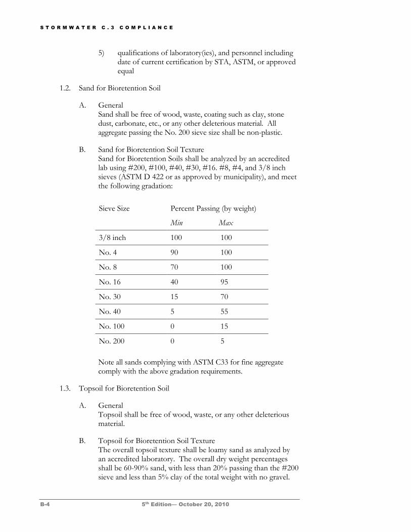
S T O R M W A T E R C . 3 C O M P L I A N C E
B-4 5th Edition— October 20, 2010
5) qualifications of laboratory(ies), and personnel including date of current certification by STA, ASTM, or approved equal
1.2. Sand for Bioretention Soil
A. General Sand shall be free of wood, waste, coating such as clay, stone dust, carbonate, etc., or any other deleterious material. All aggregate passing the No. 200 sieve size shall be non-plastic.
B. Sand for Bioretention Soil Texture Sand for Bioretention Soils shall be analyzed by an accredited lab using #200, #100, #40, #30, #16. #8, #4, and 3/8 inch sieves (ASTM D 422 or as approved by municipality), and meet the following gradation:
Note all sands complying with ASTM C33 for fine aggregate comply with the above gradation requirements.
1.3. Topsoil for Bioretention Soil
A. General Topsoil shall be free of wood, waste, or any other deleterious material.
B. Topsoil for Bioretention Soil Texture The overall topsoil texture shall be loamy sand as analyzed by an accredited laboratory. The overall dry weight percentages shall be 60-90% sand, with less than 20% passing than the #200 sieve and less than 5% clay of the total weight with no gravel.
Sieve Size Percent Passing (by weight)
Min Max
3/8 inch 100 100
No. 4 90 100
No. 8 70 100
No. 16 40 95
No. 30 15 70
No. 40 5 55
No. 100 0 15
No. 200 0 5
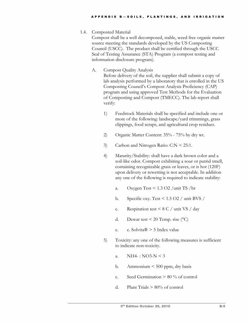
A P P E N D I X B — S O I L S , P L A N T I N G S , A N D I R R I G A T I O N
5th Edition October 20, 2010 B-5
1.4. Composted Material Compost shall be a well decomposed, stable, weed free organic matter source meeting the standards developed by the US Composting Council (USCC). The product shall be certified through the USCC Seal of Testing Assurance (STA) Program (a compost testing and information disclosure program).
A. Compost Quality Analysis Before delivery of the soil, the supplier shall submit a copy of lab analysis performed by a laboratory that is enrolled in the US Composting Council’s Compost Analysis Proficiency (CAP) program and using approved Test Methods for the Evaluation of Composting and Compost (TMECC). The lab report shall verify:
1) Feedstock Materials shall be specified and include one or more of the following: landscape/yard trimmings, grass clippings, food scraps, and agricultural crop residues.
2) Organic Matter Content: 35% - 75% by dry wt.
3) Carbon and Nitrogen Ratio: C:N < 25:1.
4) Maturity/Stability: shall have a dark brown color and a soil-like odor. Compost exhibiting a sour or putrid smell, containing recognizable grass or leaves, or is hot (120F) upon delivery or rewetting is not acceptable. In addition any one of the following is required to indicate stability:
a. Oxygen Test < 1.3 O2 /unit TS /hr
b. Specific oxy. Test < 1.5 O2 / unit BVS /
c. Respiration test < 8 C / unit VS / day
d. Dewar test < 20 Temp. rise (°C)
e. e. Solvita® > 5 Index value
5) Toxicity: any one of the following measures is sufficient to indicate non-toxicity.
a. NH4- : NO3-N < 3
b. Ammonium < 500 ppm, dry basis
c. Seed Germination > 80 % of control
d. Plant Trials > 80% of control
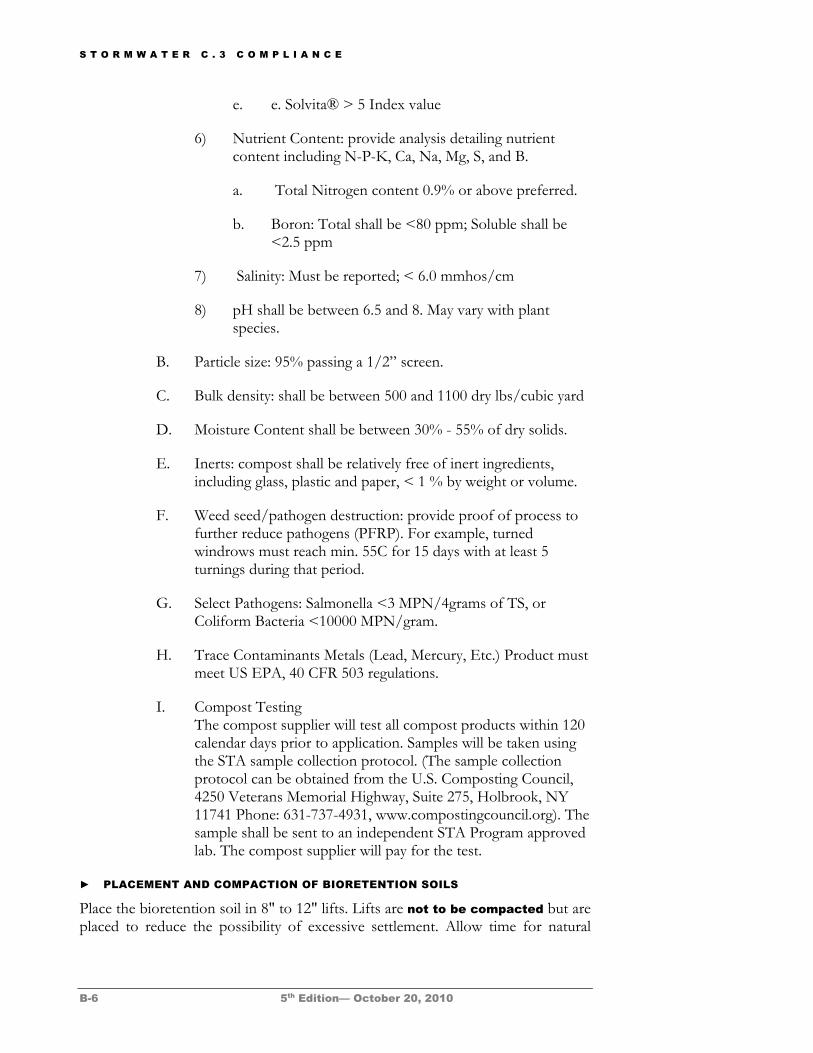
S T O R M W A T E R C . 3 C O M P L I A N C E
B-6 5th Edition— October 20, 2010
e. e. Solvita® > 5 Index value
6) Nutrient Content: provide analysis detailing nutrient content including N-P-K, Ca, Na, Mg, S, and B.
a. Total Nitrogen content 0.9% or above preferred.
b. Boron: Total shall be <80 ppm; Soluble shall be <2.5 ppm
7) Salinity: Must be reported; < 6.0 mmhos/cm
8) pH shall be between 6.5 and 8. May vary with plant species.
B. Particle size: 95% passing a 1/2” screen.
C. Bulk density: shall be between 500 and 1100 dry lbs/cubic yard
D. Moisture Content shall be between 30% - 55% of dry solids.
E. Inerts: compost shall be relatively free of inert ingredients, including glass, plastic and paper, < 1 % by weight or volume.
F. Weed seed/pathogen destruction: provide proof of process to further reduce pathogens (PFRP). For example, turned windrows must reach min. 55C for 15 days with at least 5 turnings during that period.
G. Select Pathogens: Salmonella <3 MPN/4grams of TS, or Coliform Bacteria <10000 MPN/gram.
H. Trace Contaminants Metals (Lead, Mercury, Etc.) Product must meet US EPA, 40 CFR 503 regulations.
I. Compost Testing The compost supplier will test all compost products within 120 calendar days prior to application. Samples will be taken using the STA sample collection protocol. (The sample collection protocol can be obtained from the U.S. Composting Council, 4250 Veterans Memorial Highway, Suite 275, Holbrook, NY 11741 Phone: 631-737-4931, www.compostingcouncil.org). The sample shall be sent to an independent STA Program approved lab. The compost supplier will pay for the test.
► PLACEMENT AND COMPACTION OF BIORETENTION SOILS
Place the bioretention soil in 8" to 12" lifts. Lifts are not to be compacted but are placed to reduce the possibility of excessive settlement. Allow time for natural
A P P E N D I X B — S O I L S , P L A N T I N G S , A N D I R R I G A T I O N
5th Edition October 20, 2010 B-7
compaction and settlement prior to planting. Bioretention soil may be watered to encourage compaction.
Plantings ► PLANT SELECTION GUIDELINES
The plants tabulated in Attachment B-1 were selected for the following characteristics:
Adaptation to Contra Costa’s climate
Drought tolerance
Adaptation to well-drained soils
Adaptation to low soil fertility
Allow infiltration
Are not invasive weeds
Do not have aggressive roots
Characteristics noted in the table, including irrigation preferences and ability to tolerate heat, coastal conditions, flooding, and wind should be considered when selecting plants.
This list is not comprehensive, nor will all these species succeed at every site. Selection for a particular site should be done by experienced professionals familiar with the plants and site conditions. Avoid planting species on the California Invasive Plant Council’s invasive plant inventory list.
► PLANT INSTALLATION
Trees and large shrubs installed in bioretention facilities are susceptible to blowing over before roots are established. They should be staked securely. Three stakes per tree are recommended at windy sites. Straps should be inspected once or twice a year and removed once trees are established to prevent girdling.
► FERTILIZATION
Due to the potential for conveying nutrients to storm drains, no fertilizer should be added to bioretention facilities or planter boxes. Compost tea, available from various nurseries and garden supply retailers, may be applied at a recommended rate of 5 gallons mixed with 15 gallons of water per acre.
Compost tea can be applied up to two weeks prior to planting and once per year between March and June. Application is not recommended when temperatures are
S T O R M W A T E R C . 3 C O M P L I A N C E
B-8 5th Edition— October 20, 2010
below 50°F or above 90°F or when rain is forecast in the next 48 hours. Additional applications may be made as needed to correct nutrient deficiencies.
► MULCH
Mulch is not required but is recommended for the purpose of retaining moisture, preventing erosion and minimizing weed growth. Aged mulch, also called compost mulch, reduces the ability of weeds to establish, keeps soil moist, and replenishes soil nutrients. Aged mulch can be obtained through soil suppliers or directly from commercial recycling yards. Apply 1" to 2" of composted mulch, once a year, preferably in June following weeding.
Compared to bark mulch, aged mulch has somewhat less of a tendency to float into overflow inlets during intense storms. To reduce mulch entering overflow inlets, it is recommended to use atrium or beehive grates with ¼" openings over overflow inlets.
► WEED CONTROL
Weeds should be controlled primarily by manual methods and soil amendment. In response to problem areas or threatening invasions, corn gluten, white vinegar, vinegar-based products such as Burn-out, or non-selective natural herbicides such as Safer’s Sharpshooter may be used.
► PEST AND DISEASE CONTROL
Synthetic pesticides should not be used on bioretention facilities. Beneficial nematodes and non-toxic controls may be used. Acceptable natural pesticides include Safer® Aphid, Whitefly, and Mealybug Killer, Safer® Tree and Shrub Insect Attach, Safer® for Evergreens, and Neem oil.
Irrigation Bioretention soils have a high infiltration rate and require a different irrigation system design than what is typically used for heavy clay soils in Contra Costa County. Irrigation systems must be designed to minimize water use, avoid overwatering, and prevent the underdrain discharges during dry weather.
Bioretention facilities and planter boxes may need to be irrigated more than once a day. Irrigation controls should allow separate control of times and durations of irrigation for bioretention facilities and planter boxes vs. other landscape areas.
Smart irrigation controllers are strongly encouraged. Available controllers may access weather stations, use sensors to measure soil temperature and moisture, and allow input of soil types, plant types, root depth, light conditions, slope, and usable rainfall.
Drip emitters are strongly recommended over spray irrigation. Use multiple, lower-flow (one-half to two gallons per hour) emitters in fast-draining
A P P E N D I X B — S O I L S , P L A N T I N G S , A N D I R R I G A T I O N
5th Edition October 20, 2010 B-9
bioretention soils. Use two or more emitters for perennials, ground covers, and bunchgrasses. Four to six emitters may be needed for larger shrubs and trees. Some types of emitters encourage horizontal distribution of water.
Spray heads must be positioned to avoid direct spray into bioretention facility or planter box outlet structures.
References and Resources Recommendations for Soils Specification, Planting, and Irrigation of Bioretention Facilities,
WRA Environmental Consultants, November 5, 2008.
US Composting Council
Plant List and Planting Guidance for Landscape-Based Stormwater Measures. Appendix B in the ASTM International
Alameda County Clean Water Program C.3 Technical Guidance (2006).
Plants and Landscapes for Summer Dry Climates. Nora Harlow, Ed. East Bay Municipal Utility District, Oakland California Native Plants for Your Garden and Wildlife, Las Pilitas Nursery, 2008. Native Treasures: Gardening with the Plants of California. M. Nevin Smith, 2006. University of California Press.
The Califlora Database, 2008.
California Invasive Plant Council A Guide to Estimating Irrigation Water Needs of Landscape Plantings in California, University of California Cooperative Extension and California Department of Water Resources
Our Water Our World, website to developed to assist consumers in managing home and garden pests in a way that helps protect water.
Bay-Friendly Landscaping for Professionals, a whole systems approach to the design, construction, and maintenance of the landscape to support the integrity of the San Francisco Bay watershed.
University of California Statewide Integrated Pest Management (IPM) Program
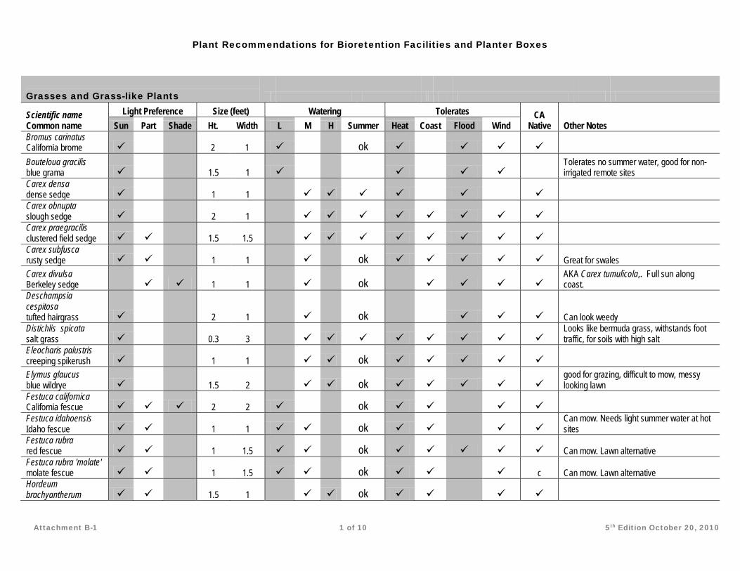
Plant Recommendations for Bioretention Facilities and Planter Boxes
Attachment B-1 1 of 10 5th Edition October 20, 2010
Grasses and Grass-like Plants
Scientific name Common name
Light Preference Size (feet) Watering Tolerates CA Native Other Notes Sun Part Shade Ht. Width L M H Summer Heat Coast Flood Wind
Bromus carinatus California brome
2 1
ok
Bouteloua gracilis blue grama
1.5 1
Tolerates no summer water, good for non-irrigated remote sites
Carex densa dense sedge
1 1
Carex obnupta slough sedge
2 1
Carex praegracilis clustered field sedge
1.5 1.5
Carex subfusca rusty sedge
1 1
ok Great for swales
Carex divulsa Berkeley sedge
1 1
ok
AKA Carex tumulicola,. Full sun along coast.
Deschampsia cespitosa tufted hairgrass
2 1
ok
Can look weedy
Distichlis spicata salt grass
0.3 3
Looks like bermuda grass, withstands foot traffic, for soils with high salt
Eleocharis palustris creeping spikerush
1 1
ok
Elymus glaucus blue wildrye
1.5 2
ok
good for grazing, difficult to mow, messy looking lawn
Festuca californica California fescue 2 2
ok
Festuca idahoensis Idaho fescue
1 1
ok
Can mow. Needs light summer water at hot sites
Festuca rubra red fescue
1 1.5
ok Can mow. Lawn alternative
Festuca rubra 'molate' molate fescue
1 1.5
ok
c Can mow. Lawn alternative
Hordeum brachyantherum
1.5 1
ok
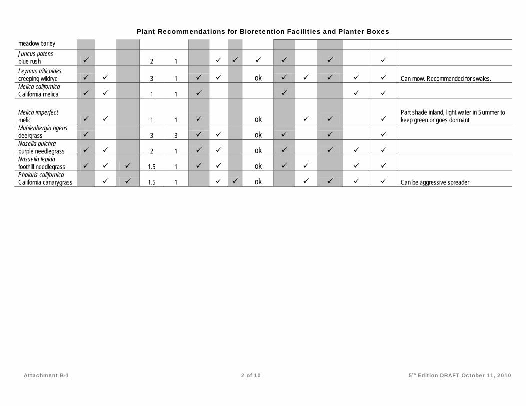
Plant Recommendations for Bioretention Facilities and Planter Boxes
Attachment B-1 2 of 10 5th Edition DRAFT October 11, 2010
meadow barley Juncus patens blue rush
2 1
Leymus triticoides creeping wildrye
3 1
ok Can mow. Recommended for swales.
Melica californica California melica
1 1
Melica imperfect melic
1 1
ok
Part shade inland, light water in Summer to keep green or goes dormant
Muhlenbergia rigens deergrass
3 3
ok
Nasella pulchra purple needlegrass
2 1
ok
Nassella lepida foothill needlegrass 1.5 1
ok
Phalaris californica California canarygrass
1.5 1
ok
Can be aggressive spreader
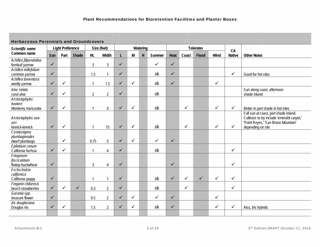
Plant Recommendations for Bioretention Facilities and Planter Boxes
Attachment B-1 3 of 10 5th Edition DRAFT October 11, 2010
Herbaceous Perennials and Groundcovers Scientific name Common name
Light Preference Size (feet) Watering Tolerates CA Native Other Notes Sun Part Shade Ht. Width L M H Summer Heat Coast Flood Wind
Achillea filipendulina fernleaf yarrow
3 3
Achillea millefolium common yarrow
1.5 1
ok
Good for hot sites
Achillea tomentosa woolly yarrow
1 1.5
ok
Aloe striata coral aloe
2 2
ok
Sun along coast, afternoon shade inland
Arctostaphylos hookeri Monterey manzanita
1 4
ok
Better in part shade in hot sites
Arctostaphylos uva-ursi kinnick-kinnick
1 15
ok
Full sun at coast, part shade inland. Cultivars to try include 'emerald carpet,' 'Point Reyes,' 'San Bruno Mountain' depending on site
Ceratostigma plumbaginoides dwarf plumbago
0.75 5
Epilobium canum California fuchsia
1 4
ok
Eriogonum fasciculatum flattop buckwheat
3 4
Eschscholzia californica California poppy
1 1
ok
Fragaria chiloensis beach strawberries 0.3 2
ok
Gazania spp. treasure flower
0.5 2
Iris douglasiana Douglas iris
1.5 2
ok
Also, Iris hybrids
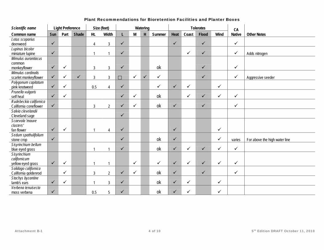
Plant Recommendations for Bioretention Facilities and Planter Boxes
Attachment B-1 4 of 10 5th Edition DRAFT October 11, 2010
Scientific name Light Preference Size (feet) Watering Tolerates CA Native Other Notes Common name Sun Part Shade Ht. Width L M H Summer Heat Coast Flood Wind
Lotus scoparius deerweed
4 3
Lupinus bicolor miniature lupine
1 1
Adds nitrogen
Mimulus aurantiacus common monkeyflower
3 3
ok
Mimulus cardinalis scarlet monkeyflower 3 3
Aggressive seeder
Polygonum capitatum pink knotweed
0.5 4
Prunella vulgaris self heal
ok
Rudebeckia californica California coneflower
3 2
ok
Salvia clevelandii Cleveland sage
Scaevola 'mauve clusters' fan flower
1 4
Sedum spathulifolium stone crop
ok
varies For above the high water line
Sisyrinchium bellum blue eyed grass
1 1
ok
Sisyrinchium californicum yellow eyed grass
1 1
Solidago californica California goldenrod
3 2
ok
Stachys byzantine lamb's ears
1 3
ok
Verbena tenuisecta moss verbena
0.5 5
ok
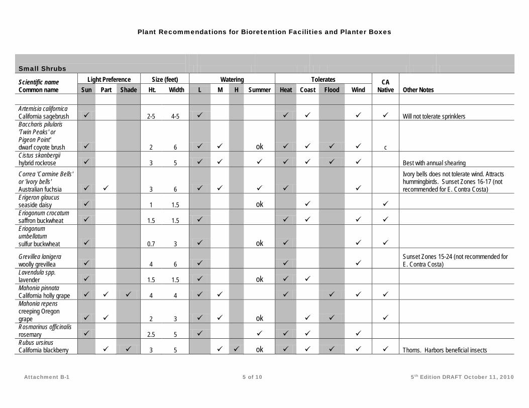
Plant Recommendations for Bioretention Facilities and Planter Boxes
Attachment B-1 5 of 10 5th Edition DRAFT October 11, 2010
Small Shrubs
Scientific name Common name
Light Preference Size (feet) Watering Tolerates CA Native Other Notes Sun Part Shade Ht. Width L M H Summer Heat Coast Flood Wind
Artemisia californica California sagebrush
2-5 4-5
Will not tolerate sprinklers
Baccharis pilularis 'Twin Peaks' or Pigeon Point' dwarf coyote brush
2 6
ok c
Cistus skanbergii hybrid rockrose
3 5
Best with annual shearing
Correa 'Carmine Bells' or 'ivory bells' Australian fuchsia
3 6
Ivory bells does not tolerate wind. Attracts hummingbirds. Sunset Zones 16-17 (not recommended for E. Contra Costa)
Erigeron glaucus seaside daisy
1 1.5
ok
Eriogonum crocatum saffron buckwheat
1.5 1.5
Eriogonum umbellatum sulfur buckwheat
0.7 3
ok
Grevillea lanigera woolly grevillea
4 6
Sunset Zones 15-24 (not recommended for E. Contra Costa)
Lavendula spp. lavender
1.5 1.5
ok
Mahonia pinnata California holly grape 4 4
Mahonia repens creeping Oregon grape
2 3
ok
Rosmarinus officinalis rosemary
2.5 5
Rubus ursinus California blackberry
3 5
ok Thorns. Harbors beneficial insects
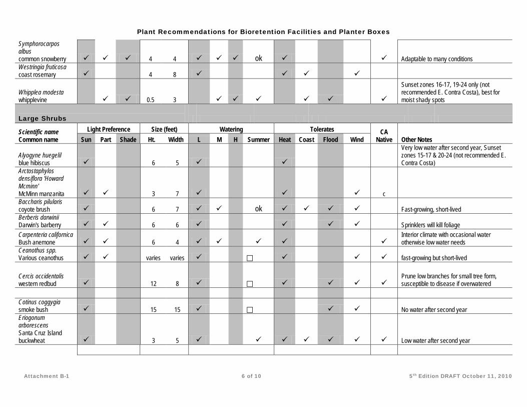
Plant Recommendations for Bioretention Facilities and Planter Boxes
Attachment B-1 6 of 10 5th Edition DRAFT October 11, 2010
Symphorocarpos albus common snowberry 4 4 ok
Adaptable to many conditions
Westringia fruticosa coast rosemary
4 8
Whipplea modesta whipplevine
0.5 3
Sunset zones 16-17, 19-24 only (not recommended E. Contra Costa), best for moist shady spots
Large Shrubs
Scientific name Common name
Light Preference Size (feet) Watering Tolerates CA Native Other Notes Sun Part Shade Ht. Width L M H Summer Heat Coast Flood Wind
Alyogyne huegelil blue hibiscus
6 5
Very low water after second year, Sunset zones 15-17 & 20-24 (not recommended E. Contra Costa)
Arctostaphylos densiflora 'Howard Mcminn' McMinn manzanita
3 7
c
Baccharis pilularis coyote brush
6 7
ok Fast-growing, short-lived
Berberis darwinii Darwin's barberry
6 6
Sprinklers will kill foliage
Carpenteria californica Bush anemone
6 4
Interior climate with occasional water otherwise low water needs
Ceanothus spp. Various ceanothus
varies varies
fast-growing but short-lived
Cercis occidentalis western redbud
12 8
Prune low branches for small tree form, susceptible to disease if overwatered
Cotinus coggygia smoke bush
15 15
No water after second year
Eriogonum arborescens Santa Cruz Island buckwheat
3 5
Low water after second year
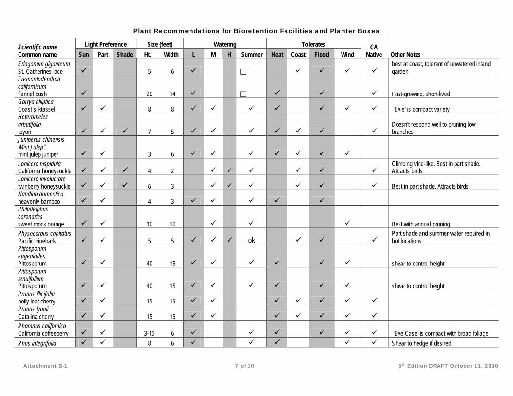
Plant Recommendations for Bioretention Facilities and Planter Boxes
Attachment B-1 7 of 10 5th Edition DRAFT October 11, 2010
Scientific name Common name
Light Preference Size (feet) Watering Tolerates CA Native Other Notes Sun Part Shade Ht. Width L M H Summer Heat Coast Flood Wind
Eriogonum giganteum St. Catherines lace
5 6
best at coast, tolerant of unwatered inland garden
Fremontodendron californicum flannel bush
20 14
Fast-growing, short-lived
Garrya elliptica Coast silktassel
8 8
'Evie' is compact variety
Heteromeles arbutifolia toyon 7 5
Doesn't respond well to pruning low branches
Juniperus chinensis 'Mint Julep" mint julep juniper
3 6
Lonicera hispidula California honeysuckle 4 2
Climbing vine-like. Best in part shade. Attracts birds
Lonicera involucrate twinberry honeysuckle 6 3
Best in part shade. Attracts birds
Nandina domestica heavenly bamboo
4 3
Philadelphus coronaries sweet mock orange
10 10
Best with annual pruning
Physocarpus capitatus Pacific ninebark
5 5 ok
Part shade and summer water required in hot locations
Pittosporum eugeniodes Pittosporum
40 15
shear to control height
Pittosporum tenuifolium Pittosporum
40 15
shear to control height
Prunus illicifolia holly leaf cherry
15 15
Prunus lyonii Catalina cherry
15 15
Rhamnus californica California coffeeberry
3-15 6
'Eve Case' is compact with broad foliage
Rhus integrifolia
8 6
Shear to hedge if desired
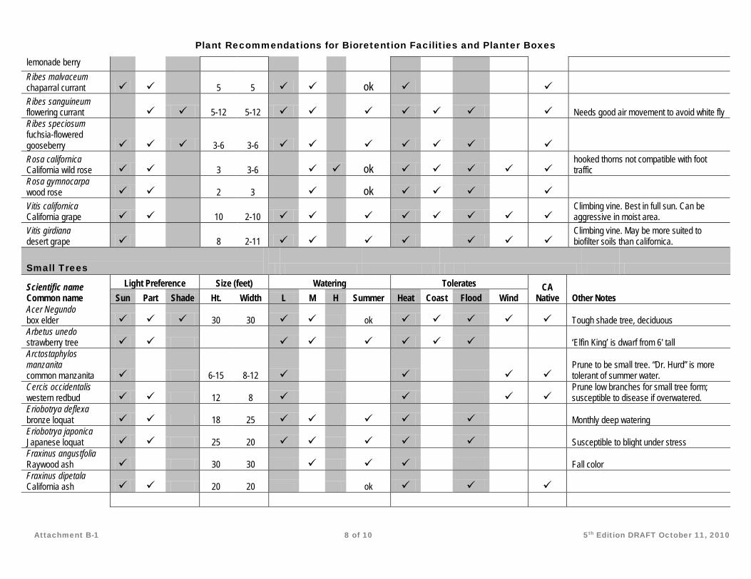
Plant Recommendations for Bioretention Facilities and Planter Boxes
Attachment B-1 8 of 10 5th Edition DRAFT October 11, 2010
lemonade berry Ribes malvaceum chaparral currant
5 5
ok
Ribes sanguineum flowering currant
5-12 5-12
Needs good air movement to avoid white fly
Ribes speciosum fuchsia-flowered gooseberry 3-6 3-6
Rosa californica California wild rose
3 3-6
ok
hooked thorns not compatible with foot traffic
Rosa gymnocarpa wood rose
2 3
ok
Vitis californica California grape
10 2-10
Climbing vine. Best in full sun. Can be aggressive in moist area.
Vitis girdiana desert grape
8 2-11
Climbing vine. May be more suited to biofilter soils than californica.
Small Trees
Scientific name Common name
Light Preference Size (feet) Watering Tolerates CA Native Other Notes Sun Part Shade Ht. Width L M H Summer Heat Coast Flood Wind
Acer Negundo box elder 30 30 ok Tough shade tree, deciduous Arbetus unedo strawberry tree ‘Elfin King’ is dwarf from 6' tall Arctostaphylos manzanita common manzanita 6-15 8-12
Prune to be small tree. “Dr. Hurd” is more tolerant of summer water.
Cercis occidentalis western redbud 12 8
Prune low branches for small tree form; susceptible to disease if overwatered.
Eriobotrya deflexa bronze loquat 18 25 Monthly deep watering Eriobotrya japonica Japanese loquat 25 20 Susceptible to blight under stress Fraxinus angustfolia Raywood ash 30 30 Fall color Fraxinus dipetala California ash 20 20 ok
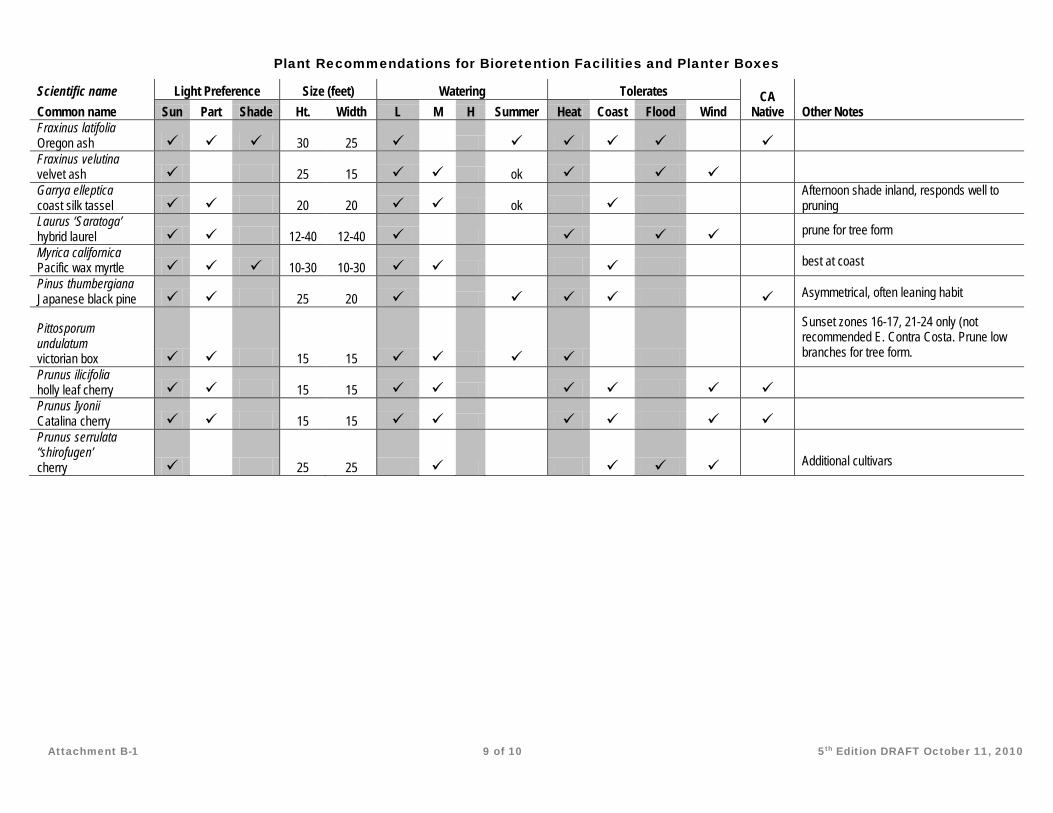
Plant Recommendations for Bioretention Facilities and Planter Boxes
Attachment B-1 9 of 10 5th Edition DRAFT October 11, 2010
Scientific name Light Preference Size (feet) Watering Tolerates CA Native Other Notes Common name Sun Part Shade Ht. Width L M H Summer Heat Coast Flood Wind
Fraxinus latifolia Oregon ash 30 25 Fraxinus velutina velvet ash 25 15 ok Garrya elleptica coast silk tassel 20 20 ok
Afternoon shade inland, responds well to pruning
Laurus ‘Saratoga’ hybrid laurel 12-40 12-40 prune for tree form Myrica californica Pacific wax myrtle 10-30 10-30 best at coast Pinus thumbergiana Japanese black pine 25 20 Asymmetrical, often leaning habit
Pittosporum undulatum victorian box 15 15
Sunset zones 16-17, 21-24 only (not recommended E. Contra Costa. Prune low branches for tree form.
Prunus ilicifolia holly leaf cherry 15 15 Prunus Iyonii Catalina cherry 15 15 Prunus serrulata “shirofugen’ cherry 25 25 Additional cultivars
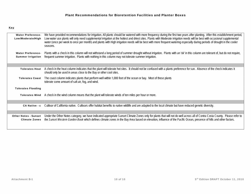
Plant Recommendations for Bioretention Facilities and Planter Boxes
Attachment B-1 10 of 10 5th Edition DRAFT October 11, 2010
Key
Water Preference- Low/Moderate/High
We have provided recommendations for irrigation. All plants should be watered with more frequency during the first two years after planting. After this establishment period, Low water use plants will only need supplemental irrigation at the hottest and driest sites. Plants with Moderate irrigation needs will be best with occasional supplemental water (once per week to once per month) and plants with High irrigation needs will be best with more frequent watering especially during periods of drought in the cooler seasons.
Water Preference- Summer Irrigation
Plants with a check in this column will not withstand a long period of summer drought without irrigation. Plants with an 'ok' in this column are tolerant of, but do not require, frequent summer irrigation. Plants with nothing in this column may not tolerate summer irrigation.
Tolerates Heat A check in the heat column indicates that the plant will tolerate hot sites. It should not be confused with a plants preference for sun. Absence of the check indicates it
should only be used in areas close to the Bay or other cool sites.
Tolerates Coast The coast column indicates plants that perform well within 1,000 feet of the ocean or bay. Most of these plants tolerate some amount of salt air, fog, and wind.
Tolerates Flooding
Tolerates Wind A check in the wind column means that the plant will tolerate winds of ten miles per hour or more.
CA Native - c Cultivar of California native. Cultivars offer habitat benefits to native wildlife and are adapted to the local climate but have reduced genetic diversity.
Other Notes - Sunset
Climate Zones Under the Other Notes category, we have indicated appropriate Sunset Climate Zones only for plants that will not do well across all of Contra Costa County. Please refer to the Sunset Western Garden Book which defines climate zones in the Bay Area based on elevation, influence of the Pacific Ocean, presence of hills and other factors.

5th Edition — October 20, 2010
Flow Control Instructions and tools for meeting flow-control (hydrograph modification management) requirements.
rovision C.3.g in the MRP states:
Stormwater discharges from [applicable] projects shall not cause an increase in the erosion potential of the receiving stream over the pre-projct (existing) condition. Increases in runoff flow and volume shall be managed so that post-proejct runoff shall not exceed pre-project rates and durations, where such increased flow and/or volume is likely to cause increased potential for erosion of creek beds and banks, silt pollutant generation, or other adverse impacts on beneficial uses due to increased erosive force.
As required by a 2003 amendment to the previous NPDES permit, the CCCWP submitted a Hydrograph Modification Management Plan (HMP), including a proposed flow-control standard, in July 2005. The flow-control standard was retained in the MRP issued in October 2009. See Attachment C-1.
The flow-control standard applies to projects which create or replace one acre or more of impervious area and for which applications for development approvals are deemed complete after October 14, 2006. See Chapter 1, including Table 1-1.
Appendix
C
P
Appendix C Contents
Flow Control Overview ................................................ C-1 Options for Flow-Control Compliance:
1: No Increase in Impervious Area .................... C-3 2: Integrated Management Practices ................... C-5 3: Model Pre- and Post-Project Runoff ............... C-5 4a: Low Risk of Accelerated Erosion .................. C-9 4b: Medium Risk of Accelerated Erosion .......... C-11 4c: High Risk of Accelerated Erosion ............... C-13
References and Resources ............................................ C-15 Attachments:
C-1: Hydrograph Modification Management Standard
S T O R M W A T E R C . 3 C O M P L I A N C E
C-2 5th Edition October 20, 2010
The flow-control standard is preventative: project proponents are encouraged to design their projects so there will be no increase in runoff as compared to the pre-project condition of the development site. The CCCWP has created designs and design aids for Low Impact Development Integrated Management Practices (IMPs) which may be used to achieve this criterion.
However, increased runoff is allowed if it can be demonstrated the increases are unlikely to cause downstream erosion or other impacts on beneficial uses of streams. This may be the case either because the drainage downstream between the project site and the Bay/Delta is in pipes or in channels that are tidally influenced or aggrading. Or the applicant may propose a stream restoration project or projects which fully mitigate the erosion risk.
Comparison of post-project to pre-project flows is based on continuous simulation of runoff over a period of 30 years or more, using local hourly rainfall data, and statistical analysis of peak flow recurrence and of the cumulative duration of flows. See the discussion in Chapter 2.
To demonstrate compliance with the standard, select one of the following four options:
Option 1. Demonstrate the project produces no net increase in impervious area. A simple inventory and accounting of existing and proposed impervious area is required. You will also need to show, qualitatively, that changes to drainage facilities will not increase the efficiency of drainage collection and conveyance.
Option 2. Implement IMPs such as planters, swales, and bioretention areas using the Program’s low-impact development site design procedure and facility sizing tool. Applicable criteria, including runoff factors and IMP sizing ratios, have been selected to meet the flow-control standard and are incorporated into the tool.
Option 3. Use a continuous-simulation hydrologic computer model such as USEPA’s Hydrologic Simulation Program—Fortran (HSPF) to simulate pre-project and post-project runoff, including the effect of proposed IMPs, detention basins, or other storwmater management facilities. An hourly rainfall record of at least 30 years must be used. Compile flow statistics and produce summary peak flow and flow duration graphics to demonstrate the following criteria are met:
For flow rates from 10% of the pre-project 2-year runoff event (0.1Q2) to the pre-project 10-year runoff event (Q10), the post-project discharge rates and durations shall not deviate above the pre-project rates and durations by more than 10% over more than 10% of the length of the flow duration curve.
I C O N K E Y
Helpful Tip
Submittal Requirement
Terms to Look Up
References & Resources
A P P E N D I X C — F L O W C O N T R O L
5th Edition October 20, 2010 C-3
For flow rates from 0.5Q2 to Q2, the post project peak flows shall not exceed pre-project peak flows. For flow rates from Q2 to Q10, post-project peak flows may exceed pre-project flows by up to 10% for a 1-year frequency interval. For example, post-project flows could exceed pre-project flows by up to 10% for the interval from Q9 to Q10 or from Q5.5 to Q6.5, but not from Q8 to Q10.
Option 4. Show that, because of the specific characteristics of the stream receiving runoff from the project site, or because of proposed channel restoration projects, or both, there is little likelihood the cumulative impacts from new development could increase the net rate of stream erosion significantly.
Option 4a. Low Risk. Show all downstream reaches, from the project site to the Bay/Delta, are enclosed pipes, hardened channels, subject to tidal action, or aggrading.
Option 4b. Medium Risk. Use the methods and criteria in this Appendix to confirm each reach downstream from the project to the Bay/Delta meets criteria for the “medium risk” (or “low-risk”) classification. Implement an in-stream mitigation project to stabilize stream beds or banks, improve natural stream functions, and/or improve habitat values. The expected environmental benefits of the mitigation project must substantially outweigh the potential impacts of an increase in runoff from the development project.
Option 4c. High Risk. Implement a comprehensive program of in-stream measures to improve stream channel hydrological and ecological functions while accommodating increased flows.
Whichever option is used to demonstrate flow control compliance, projects must also meet the C.3 treatment requirements. Under Option 2, projects can meet both the treatment and flow control requirements by using the low-impact development site design procedure and facility sizing tool. The following sections contain instructions and references to assist you.
Option 1: No increase in impervious area This option applies to sites which have been previously developed. To use Option 1, simply compare existing to proposed impervious area. You will also need to show, qualitatively, that changes to drainage facilities will not increase the efficiency of drainage collection and conveyance.
► RATIONALE
In many` cases, redevelopment of a previously built site will result in decreases in total impervious area—because of setback and landscaping requirements and use
S T O R M W A T E R C . 3 C O M P L I A N C E
C-4 5th Edition October 20, 2010
of IMPs to treat runoff. Even when sized for stormwater treatment only, IMPs also reduce runoff peaks and durations considerably. The combination of decreased impervious area and IMPs practically assures that post-project runoff will not exceed pre-project peaks and durations.
► MEETING THE REQUIREMENTS
Use a base map or aerial photo.
Identify existing roofs, paved areas, and other impervious surfaces.
Delineate the impervious areas, dividing them to facilitate identification of each area and estimation of its square footage.
Mark each delineated area with a unique identifier and calculated square footage.
Prepare a table listing each delineated area and its square footage and show a total for the project site.
Refer to the table of areas you prepared for the design of treatment facilities (Chapter 3, Step 3). Sum the impervious areas. Do not include pervious pavements or other pervious surfaces in this sum.
► PREPARING YOUR SUBMITTAL
See the instructions in Chapter 3, Step 2, regarding assessment of site opportunities and constraints to reduce imperviousness and retain or detain site drainage and in Chapter 3, Step 3, regarding design features and surface treatments used to minimize imperviousness. Make sure this information is included in your Stormwater Control Plan.
Include in your Stormwater Control Plan, as an attachment, figure, or exhibit, the marked-up base map or aerial photo showing existing impervious surfaces.
Include in your Stormwater Control Plan the tabulation and sum of existing impervious areas and a comparison to the total proposed impervious area.
If you used the recommended Low Impact Development design procedure (Chapter 4), including sizing IMPs for stormwater treatment only, no further documentation of reduced drainage efficiency is required. If you used a different design procedure to design stormwater treatment facilities, describe the existing and proposed drainage systems and explain, qualitatively or quantitatively:
Why the time of concentration is increased as a result of the proposed development, and
Why the total volume of runoff is reduced as a result of the proposed development.
A P P E N D I X C — F L O W C O N T R O L
5th Edition October 20, 2010 C-5
Option 2: Integrated Management Practices Most applicants will find it easiest and most cost-effective to use this option. Use the Program’s Design and Documentation Procedure for Low Impact Development (Chapter 4) to select and size swales, planter boxes, bioretention areas, or other IMPs to meet both treatment and flow-control requirements for your project.
► RATIONALE
The Program developed designs and sizing factors for a variety of IMPs. The sizing factor applicable to a particular IMP is dependent on the soil type and rainfall pattern at the development site. The sizing factors were calculated to ensure runoff discharged from the IMP does not exceed the pre-project peaks and durations of runoff from the area tributary to the IMP. See Chapter Two, Chapter Four, and the Program’s Hydrograph Modification Management Plan for more background on calculation of the IMP sizing factors.
► MEETING THE REQUIREMENTS
Follow the instructions in Chapter Four to size IMPs. The Program’s IMP sizing tool, which is available on the Program’s C.3 web page, may be used to facilitate calculations. Select the “Treatment and Flow Control” option to size IMPs to provide both treatment and flow control for site runoff.
► PREPARING YOUR SUBMITTAL
Show calculations as described in Chapter 4. Or incorporate the output from the Program’s IMP sizing tool into your Stormwater Control Plan.
Option 3: Model Pre- and Post-Project Runoff This option is for applicants who wish to design their own flow-control facilities customized to the needs and character of their development projects. It requires the development of a continuous simulation hydrologic model of the project under pre-project and post-project conditions, including the effect of proposed IMPs, detention basins, or other storwmater management facilities
Building a continuous-simulation hydrologic model for a project, and analyzing its output to compare post-project to pre-project hydrology, may be a better option than the Program’s IMP designs and sizing factors:
When it is proposed to use facilities such as detention basins, constructed wetlands, or other facilities for which the Program has not developed sizing factors.
For large drainage areas with complex drainage, steep slopes, dense vegetation, thin top soil, or other hydrological conditions where a site-
S T O R M W A T E R C . 3 C O M P L I A N C E
C-6 5th Edition October 20, 2010
specific model can provide a better representation of post-project and pre-project hydrology.
Because of the time and resources required to implement this option, it is typically applicable to larger developments (sites greater than 20 acres).
Projects that select Option 3 to meet the flow control requirements (Table 1-1) must also meet stormwater treatment requirements and LID requirements. Treatment requirements and flow-control requirements can be met via separate facilities in series, or a single facility may be designed for both treatment and flow-control. For example, a pond or wetland can serve as a treatment facility if it detains the required water quality volume for 48 hours and contains suitable design elements. To show the same pond or wetland also meets flow-control requirements, the applicant would need to construct a computer model to compare post-project to pre-project hydrology on the development site, including the hydrologic effects of the proposed pond or wetland.
Development of continuous simulation hydrologic model for a specific development site requires specialized expertise and substantial resources. Municipal staff may require the applicant to establish a force account or similar financial mechanism to provide for independent, third-party review of model documentation and output. Engineering and other design considerations related to flow-control may need to be coordinated with considerations related to flood protection and controlling other potential environmental impacts of the development.
Consult with municipal staff before beginning work on a computer model, and coordinate implementation with environmental agencies from which project approvals must be obtained.
► RATIONALE
Conventionally, drainage facilities have been designed to accommodate peak flows or volumes generated by a specific hypothetical rainfall event (design storm). The design storm is typically characterized by its recurrence interval (e.g., a 10-year or 100-year storm). Conventional drainage facilities, including flood-control basins, are designed for protection from flooding, not to protect streams from erosion.
As regulatory agencies began to develop criteria to protect streams from accelerated erosion caused by urbanization and increased imperviousness, many agencies limited the allowable increase in peak discharge associated with a specific design storm. The science of fluvial geomorphology showed that, for stable streams in undeveloped watersheds, the “channel forming flow”—the event with the most capability to move sediment—recurred approximately every 1-2 years. Initial criteria for stream protection focused on designing facilities to control peak flows from runoff events at and near this magnitude.
Further analysis of urbanizing streams indicated increases in the frequency and duration of lower flows can also contribute to accelerated stream erosion. Rainfall
A P P E N D I X C — F L O W C O N T R O L
5th Edition October 20, 2010 C-7
events which would produce little or no runoff in a pre-development watershed produce significant runoff from impervious surfaces—and that runoff is typically piped directly to streams. To fully protect streams in urbanizing watersheds from accelerated erosion, it may be necessary to control the entire regime of large and small flows.
Continuous simulation models, which typically use as input hourly rainfall data over 30 years or more, can simulate the entire runoff flow regime under existing and post-project conditions. Two sets of criteria are generally used to compare modeled pre-project and post-project flows over the long term: peak flows for each event contained in the simulation, and duration of flows at the full range of simulated flow rates.
Regardless of the hydrologic calculation method used, estimation of runoff from a particular development site requires selection of appropriate parameters to represent the quantity of rainfall that runs off versus that which puddles, infiltrates into the ground, or is absorbed by vegetation. The rational method uses “C” factors and the SCS methodology uses curve numbers to represent these relationships. Continuous simulation models, such as USEPA’s Hydrologic Simulation Program—Fortran (HSPF), use a more complex suite of parameters to characterize soils and vegetation. Values for these parameters can be calibrated to stream flow data for whole watersheds. For individual development sites, or where stream flow data is not available, appropriate values for each parameter must be estimated.
► MEETING THE REQUIREMENTS
After discussing the process for technical review with municipal staff, build and run a continuous-simulation hydrologic model of the existing site and the proposed development including detention/retention facilities. Procedures and parameters must be consistent with the instructions in the Attachment 3 to the CCCWP’s HMP. Prepare a statistical analysis of the results as described in that guidance.
► PREPARING YOUR SUBMITTAL
Provide a detailed report on the hydrologic modeling that includes, at a minimum:
An introduction that provides a description of existing site conditions, land uses and land cover and a description of the proposed project.
Separate site maps for pre-project and post-project conditions. The site maps should delineate the sub-basins used to characterize the site within the model under pre-project and post-project conditions and show a basin number or other identifier for each sub-basin. Show on your maps: hydraulic structures, roadways, drainageways, stormwater management facilities, and topography; the post-project map should also include proposed grading and site layout.
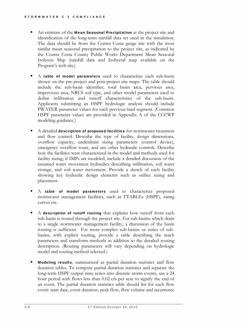
S T O R M W A T E R C . 3 C O M P L I A N C E
C-8 5th Edition October 20, 2010
An estimate of the Mean Seasonal Precipitation at the project site and identification of the long-term rainfall data set used in the simulation. The data should be from the Contra Costa gauge site with the most similar mean seasonal precipitation to the project site, as indicated by the Contra Costa County Public Works Department Mean Seasonal Isohyets Map (rainfall data and Isohyetal map available on the Program’s web site).
A table of model parameters used to characterize each sub-basin shown on the pre-project and post-project site maps. The table should include the sub-basin identifier, total basin area, pervious area, impervious area, NRCS soil type, and other model parameters used to define infiltration and runoff characteristics of the sub-basin. Applicants submitting an HSPF hydrologic analysis should include PWATER parameter values for each pervious land segment. (Common HSPF parameter values are provided in Appendix A of the CCCWP modeling guidance.)
A detailed description of proposed facilities for stormwater treatment and flow control. Describe the type of facility, design dimensions, overflow capacity, underdrain sizing parameters (control device), emergency overflow route, and any other hydraulic controls. Describe how the facilities were characterized in the model and methods used for facility sizing; if IMPs are modeled, include a detailed discussion of the assumed water movement hydraulics describing infiltration, soil water storage, and soil water movement. Provide a sketch of each facility showing key hydraulic design elements such as orifice sizing and placement.
A table of model parameters used to characterize proposed stormwater management facilities, such as FTABLEs (HSPF), rating curves etc.
A description of runoff routing that explains how runoff from each sub-basin is routed through the project site. For sub-basins which drain to a single stormwater management facility, a discussion of the basin routing is sufficient. For more complex sub-basins or series of sub-basins, with explicit routing, provide a table describing the reach parameters and transform methods in addition to the detailed routing description. (Routing parameters will vary depending on hydrologic model and routing method selected.)
Modeling results, summarized as partial duration statistics and flow duration tables. To compute partial duration statistics and separate the long-term HSPF output time series into discrete storm events, use a 24 hour period with flows less than 0.02 cfs per acre to signify the end of an event. The partial duration statistics table should list for each flow event: start date, event duration, peak flow, flow volume and recurrence
A P P E N D I X C — F L O W C O N T R O L
5th Edition October 20, 2010 C-9
interval. Show peak flow frequency and flow duration curves that illustrate the proposed project meets the peak flow control and flow duration control standard (as outlined in HMP Attachment 3).
Option 4a: Low Risk of Accelerated Erosion This option may be applicable if your project is in low-elevation areas near the Bay/Delta or an adjacent urbanized area drained by underground pipes or hardened channels. It is the responsibility of the applicant to demonstrate all downstream channels between the project site and the Bay/Delta meet the “low risk” criteria.
► RATIONALE
Flow control is not necessary if it can be demonstrated that increased flow peaks and durations would have no effect on downstream channels. “No effect” can be stipulated if it is demonstrated that the entire drainage route from the site to the Bay/Delta is in pipes, engineered hardened channels, channels subject to tidal action, or channels subject to accumulation of sediments.
For some projects, this demonstration can be a simple reference to municipal storm drain maps (for example). However, drainage channels, particularly small channels, are not always well documented. Even where drainage is documented, the boundaries of areas tributary to the drainage may be difficult to discern. For this reason, Contra Costa has not prepared a comprehensive map showing where Option 4a applies. Where necessary, applicants may need to provide field notes, photographs, or other documentation to verify the characteristics of specific reaches along the route between their project site and the Bay/Delta.
Many reaches of Contra Costa’s major creeks are natural or unhardened; Option 4a cannot be used to establish compliance with flow-control requirements for projects upstream of these reaches.
► MEETING THE REQUIREMENTS
Trace the drainage route from the project site down to the Bay/Delta. Divide the route into reaches based on the type and characteristics of drainage structures (pipe, engineered channel, natural channel). Assemble documentation and confirm each reach is in one of the following categories:
1. Enclosed pipe.
2. Channel with continuous hardened beds and banks engineered to withstand erosive forces and composed of concrete, engineered riprap, sackcrete, gabions, mats, etc. (Channel hardening must be an engineered continuous installation and not piecemealed in response to localized bank failure and erosion.)
3. Channel subject to tidal action.
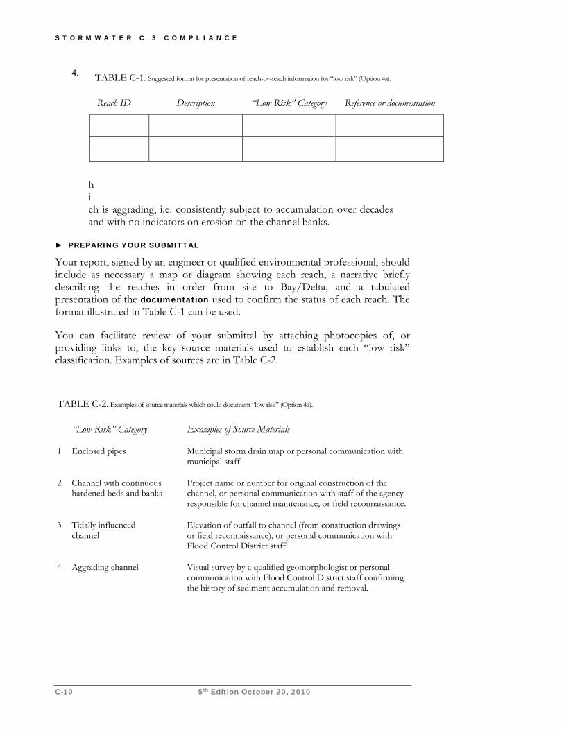
S T O R M W A T E R C . 3 C O M P L I A N C E
C-10 5th Edition October 20, 2010
4. Channel which is aggrading, i.e. consistently subject to accumulation over decades and with no indicators on erosion on the channel banks.
► PREPARING YOUR SUBMITTAL
Your report, signed by an engineer or qualified environmental professional, should include as necessary a map or diagram showing each reach, a narrative briefly describing the reaches in order from site to Bay/Delta, and a tabulated presentation of the documentation used to confirm the status of each reach. The format illustrated in Table C-1 can be used.
You can facilitate review of your submittal by attaching photocopies of, or providing links to, the key source materials used to establish each “low risk” classification. Examples of sources are in Table C-2.
TABLE C-1. Suggested format for presentation of reach-by-reach information for “low risk” (Option 4a).
Reach ID Description “Low Risk” Category Reference or documentation
TABLE C-2. Examples of source materials which could document “low risk” (Option 4a).
“Low Risk” Category Examples of Source Materials
1 Enclosed pipes Municipal storm drain map or personal communication with municipal staff
2 Channel with continuous hardened beds and banks
Project name or number for original construction of the channel, or personal communication with staff of the agency responsible for channel maintenance, or field reconnaissance.
3 Tidally influenced channel
Elevation of outfall to channel (from construction drawings or field reconnaissance), or personal communication with Flood Control District staff.
4 Aggrading channel Visual survey by a qualified geomorphologist or personal communication with Flood Control District staff confirming the history of sediment accumulation and removal.
A P P E N D I X C — F L O W C O N T R O L
5th Edition October 20, 2010 C-11
Option 4b: Medium Risk of Accelerated Erosion This option allows an applicant, in certain cases, to mitigate potential effects of increased runoff on a stream reach by sponsoring a bed or bank restoration project of limited scope.
The option is only available to projects smaller than 20 acres total area.
The applicant must first confirm downstream reaches have characteristics indicating channel beds and banks are, in the main, relatively resistant to accelerated erosion from increased runoff.
The applicant must then have a qualified geomorphologist confirm this finding and develop a proposal for a mitigation project, the benefits of which must substantially outweigh potential impacts of an increase in runoff from the proposed development project.
The applicant must also obtain concurrence from staff of regulatory agencies having jurisdiction—including Regional Water Board staff—that the mitigation project is feasible and desirable.
► RATIONALE
In a “medium risk” stream reach, the channel is stable under current conditions and may be able to absorb a slight increase in watershed imperviousness, but accelerated erosion cannot be ruled out. For some development projects upstream of these reaches, flow-control facilities may be costly or difficult to build, and the resulting benefit may be uncertain and small.
Detailed studies of the potential effects of a development on a stream can be costly, time consuming, and (in the case of a “medium risk” stream reach) could simply reiterate that increased erosion is not likely, but is possible.
As an alternative to extensive study of the stream, applicants have the option of proposing a mitigation project. Contra Costa streams have a substantial backlog of needed (but unfunded) maintenance to prevent or repair localized bank failures. Properly designed and executed, localized restoration projects can have substantial environmental benefits. Mitigation projects should seek to attenuate or reduce excessive erosive stresses (for example, by increasing channel cross section or reducing gradient), rather than just increasing shear resistance by stabilizing banks.
The benefits of the mitigation project must substantially outweigh the incremental increase in the risk of erosion due to the increased runoff represented by the project. This balance is established by the opinion of a qualified geomorphologist and then confirmed by consensus among staff of the agencies having jurisdiction.
Program consultants outlined a process and created technical tools applicants may use to implement this option. To begin the process, an engineer or qualified environmental professional can use the Program’s Basic Geomorphic Assessment
S T O R M W A T E R C . 3 C O M P L I A N C E
C-12 5th Edition October 20, 2010
procedure to evaluate downstream reaches and show each reach is either “low risk” (see Option 4a) or “medium risk.”
► MEETING THE REQUIREMENTS
Implementation of Option 4b proceeds in two phases. In the first phase, an engineer or qualified environmental professional makes a preliminary determination whether all reaches of drainage downstream from the project site to the Bay/Delta are either “low risk” or “medium risk” according to the Program’s criteria. If this determination is affirmative, the applicant may proceed to the second phase, in which a qualified stream geomorphologist confirms the preliminary determination and proposes an appropriate mitigation project.
Applicants are strongly encourage to coordinate with municipal staff, staff of the Contra Costa Flood Control and Water Conservation District, property owners of stream reaches and adjacent parcels, and regulatory agencies having jurisdiction (including the Regional Water Board and the California Department of Fish and Game) during the first phase and/or before proceeding the second phase.
First phase (conducted by an engineer, stream geomorphologist, or other qualified environmental professional): As in Option 4a, trace the drainage route from the project site down to the Bay/Delta. Divide the route into reaches based on the type and characteristics of drainage structures. Identify and assemble documentation for any “low risk” reaches as in Option 4a.
Conduct the field site review and collect the field data described in the Basic Geomorphic Assessment procedure to each of the remaining reaches downstream to the point where:
all further downstream reaches are “low risk,” or
the channel enters a publicly managed reservoir.
For each of these reaches, complete a Geomorphic Assessment Form, including field notes and photographs, to calculate the channel vulnerability indicators and evaluate the appropriate risk class. Write a narrative risk justification to accompany each assessment form.
Second phase (conducted by a qualified stream geomorphologist): Confirm the findings of the preliminary report using the information in the assessment forms, additional field data, and other available information.
Identify and describe a suitable mitigation project to stabilize stream beds or banks, improve natural stream functions, and/or improve habitat values. If a suitable project exists in the same stream reach or watershed, that project should be proposed; otherwise, a project in another watershed may be acceptable.
A P P E N D I X C — F L O W C O N T R O L
5th Edition October 20, 2010 C-13
► PREPARING YOUR SUBMITTAL
Prepare a preliminary plan and proposal for the mitigation project including milestones, schedule, cost estimates, and funding. Include a written commitment from the developer or project proponent to implement the mitigation project timely in connection with the proposed development project.
Provide an opinion and supporting analysis by one or more qualified environmental professionals that the expected environmental benefits of the mitigation project substantially outweigh the potential impacts of an increase in runoff from the development project.
To complete documentation of compliance with flow-control requirements under Option 4b, obtain letters or meeting notes in which staff representatives of regulatory agencies having jurisdiction state the project is feasible and desirable. This must include a letter signed by the Regional Water Board Executive Officer or designee referencing this requirement.
Option 4c: High Risk of Accelerated Erosion As noted at the beginning of this appendix, the Program’s flow-control standard is preventative: project proponents are encouraged to design their projects so that there will be no increase in runoff as compared to the pre-project condition of the development site. This policy aims to ensure watershed-wide increases in runoff and the attendant impacts are minimized, while obviating the need for extensive analysis to characterize the complex and unpredictable relationship between increased runoff and accelerated stream erosion in a particular watershed.
However, where it is very difficult or infeasible to achieve no increase in runoff—or in cases where a stream channel is to be restored as mitigation for other environmental impacts—an applicant may propose to alter the receiving stream channel to accommodate the predicted post-project flow regime.
The analysis required to determine design objectives for in-stream measures will typically involve watershed-scale continuous hydrologic modeling of pre-project and post-project runoff flows, sediment transport modeling, collection and/or analysis of field data to characterize channel morphology including analysis of bed and bank materials and bank vegetation, selection and design of in-stream structures, and project environmental permitting.
► RATIONALE
Stream channels which do not meet the criteria for “low-risk” (Option 4a) or “medium-risk” (Option 4b) are considered at “high-risk” of accelerated erosion due to increased watershed imperviousness. High risk channels are geomorphically unstable under existing conditions, and therefore vulnerable to any increase in impervious area.. It is presumed that increases in runoff flows to these channels will accelerate bed and bank erosion.
S T O R M W A T E R C . 3 C O M P L I A N C E
C-14 5th Edition October 20, 2010
If downstream drainage includes high-risk channels, the applicant must either control runoff flows to pre-project peaks and durations or propose a comprehensive program of in-stream measures to improve channel functions while accommodating increased flows.
► MEETING THE REQUIREMENTS
To obtain approval for a project which discharges increased runoff peaks and durations to a high-risk channel, the project proponent must perform a comprehensive analysis to determine the design objectives for channel restoration and must propose a comprehensive program of in-stream measures to improve channel functions while accommodating increased flows. Specific requirements are developed case-by-case in consultation with regulatory agencies having jurisdiction.
Different project types, channels, and locations will demand different investigative approaches; however, the following framework can be tailored to most situations:
Evaluation of watershed historic conditions.
Evaluation of channel geomorphic conditions.
Evaluation of project impacts on hydrology and sediment yield.
Prediction of impacts on receiving channels.
Design of avoidance or mitigation.
Monitoring and adaptive management.
HMP Attachment 4 includes additional detail regarding this framework and recommended evaluation method and design methods.
► PREPARING YOUR SUBMITTAL
The analysis for compliance with flow-control requirements may, and in many cases should be, integrated with analyses conducted pursuant to obtaining Clean Water Act Section 401 or Section 404 certification, CEQA, California Department of Fish and Game Stream Alteration Permits, and other regulatory approvals which may be required for the development project or implementation of in-stream measures, or both.
Discuss the contents of required submittals with the staff of agencies having jurisdiction prior to the start of the analytical work.
References and Resources Municipal Regional Permit Provision C.3.g. and Attachment C. Contra Costa Clean Water Program Final Hydrograph Modification Management Plan, revised April 19, 2006.
Attachment C-1—Excerpt from MRP Attachment C
Attachment C-1 C-1-1 Order adopted October 14, 2009
I. Demonstrating Compliance with the Standard Contra Costa Permittees shall ensure project proponents shall demonstrate compliance with the HM standard by demonstrating that any one of the following four options is met:
1. No increase in impervious area. The project proponent may compare the project design to the pre-project condition and show the project will not increase impervious area and also will not facilitate the efficiency of drainage collection and conveyance.
2. Implementation of hydrograph modification IMPs. The project proponent may select and size IMPs to manage hydrograph modification impacts, using the design procedure, criteria, and sizing factors specified in the Contra Costa Clean Water Program’s Stormwater C.3 Guidebook. The use of flow-through planters shall be limited to upper-story plazas, adjacent to building foundations, on slopes where infiltration could impair geotechnical stability, or in similar situations where geotechnical issues prevent use of IMPs that allow infiltration to native soils. Limited soil infiltration capacity in itself does not make use of other IMPs infeasible.
3. Estimated post-project runoff durations and peak flows do not exceed pre-project durations and peak flows. The project proponent may use a continuous simulation hydrologic computer model such as USEPA’s Hydrograph Simulation Program—Fortran (HSPF) to simulate pre-project and post-project runoff, including the effect of proposed IMPs, detention basins, or other stormwater management facilities. To use this method, the project proponent shall compare the pre-project and post-project model output for a rainfall record of at least 30 years, using limitations and instructions provided in the Program’s Stormwater C.3 Guidebook, and shall show the following criteria are met:
a. For flow rates from 10% of the pre-project 2-year runoff event (0.1Q2) to the pre-project 10-year runoff event (Q10), the post-project discharge rates and durations shall not deviate above the pre-project rates and durations by more than 10% over more than 10% of the length of the flow duration curve.
b. For flow rates from 0.5Q2 to Q2, the post-project peak flows shall not exceed pre-project peak flows. For flow rates from Q2 to Q10, post-project peak flows may exceed pre-project flows by up to 10% for a 1-year frequency interval. For example, post-project flows could exceed pre-project flows by up to 10% for the interval from Q9 to Q10 or from Q5.5 to Q6.5, but not from Q8 to Q10.
4. Projected increases in runoff peaks and durations will not accelerate erosion of receiving stream reaches. The project proponent may show that, because of the specific characteristics of the stream receiving runoff from the project site, or because of proposed stream restoration projects, or both, there is little likelihood that the cumulative impacts from new development could increase the net rate of stream erosion to the extent that beneficial uses would be significantly impacted. To use this option, the project proponent shall evaluate the receiving stream to determine the relative risk of erosion impacts and take the appropriate actions as described below and in Table A-1. Projects 20 acres or larger in total area shall not use the medium risk methodology in “b” below.
a. “Low Risk.” In a report or letter report, signed by an engineer or qualified environmental professional, the project proponent shall show that all downstream channels between the project site and the Bay/Delta fall into one of the following “low-risk” categories.
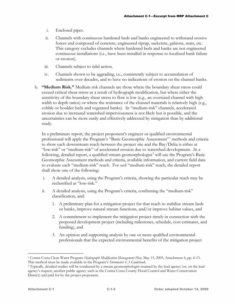
Attachment C-1—Excerpt from MRP Attachment C
Attachment C-1 C-1-2 Order adopted October 14, 2009
i. Enclosed pipes.
ii. Channels with continuous hardened beds and banks engineered to withstand erosive forces and composed of concrete, engineered riprap, sackcrete, gabions, mats, etc. This category excludes channels where hardened beds and banks are not engineered continuous installations (i.e., have been installed in response to localized bank failure or erosion).
iii. Channels subject to tidal action.
iv. Channels shown to be aggrading, i.e., consistently subject to accumulation of sediments over decades, and to have no indications of erosion on the channel banks.
b. “Medium Risk.” Medium risk channels are those where the boundary shear stress could exceed critical shear stress as a result of hydrograph modification, but where either the sensitivity of the boundary shear stress to flow is low (e.g., an oversized channel with high width to depth ratios) or where the resistance of the channel materials is relatively high (e.g., cobble or boulder beds and vegetated banks). In “medium-risk” channels, accelerated erosion due to increased watershed imperviousness is not likely but is possible, and the uncertainties can be more easily and effectively addressed by mitigation than by additional study.
In a preliminary report, the project proponent’s engineer or qualified environmental professional will apply the Program’s “Basic Geomorphic Assessment”1 methods and criteria to show each downstream reach between the project site and the Bay/Delta is either at “low-risk” or “medium-risk” of accelerated erosion due to watershed development. In a following, detailed report, a qualified stream geomorphologist2
i. A detailed analysis, using the Program’s criteria, showing the particular reach may be reclassified as “low-risk.”
will use the Program’s Basic Geomorphic Assessment methods and criteria, available information, and current field data to evaluate each “medium-risk” reach. For each “medium-risk” reach, the detailed report shall show one of the following:
ii. A detailed analysis, using the Program’s criteria, confirming the “medium-risk” classification, and:
1. A preliminary plan for a mitigation project for that reach to stabilize stream beds or banks, improve natural stream functions, and/or improve habitat values, and
2. A commitment to implement the mitigation project timely in connection with the proposed development project (including milestones, schedule, cost estimates, and funding), and
3. An opinion and supporting analysis by one or more qualified environmental professionals that the expected environmental benefits of the mitigation project
1 Contra Costa Clean Water Program Hydrograph Modification Management Plan, May 15, 2005, Attachment 4, pp. 6-13. This method must be made available in the Program’s Stormwater C.3 Guidebook. 2 Typically, detailed studies will be conducted by a stream geomorphologist retained by the lead agency (or, on the lead agency’s request, another public agency such as the Contra Costa County Flood Control and Water Conservation District) and paid for by the project proponent.
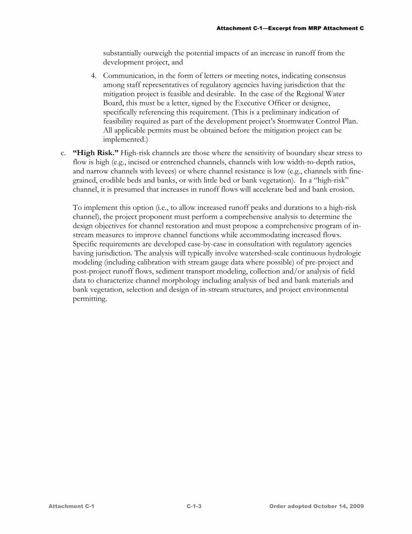
Attachment C-1—Excerpt from MRP Attachment C
Attachment C-1 C-1-3 Order adopted October 14, 2009
substantially outweigh the potential impacts of an increase in runoff from the development project, and
4. Communication, in the form of letters or meeting notes, indicating consensus among staff representatives of regulatory agencies having jurisdiction that the mitigation project is feasible and desirable. In the case of the Regional Water Board, this must be a letter, signed by the Executive Officer or designee, specifically referencing this requirement. (This is a preliminary indication of feasibility required as part of the development project’s Stormwater Control Plan. All applicable permits must be obtained before the mitigation project can be implemented.)
c. “High Risk.” High-risk channels are those where the sensitivity of boundary shear stress to flow is high (e.g., incised or entrenched channels, channels with low width-to-depth ratios, and narrow channels with levees) or where channel resistance is low (e.g., channels with fine-grained, erodible beds and banks, or with little bed or bank vegetation). In a “high-risk” channel, it is presumed that increases in runoff flows will accelerate bed and bank erosion.
To implement this option (i.e., to allow increased runoff peaks and durations to a high-risk channel), the project proponent must perform a comprehensive analysis to determine the design objectives for channel restoration and must propose a comprehensive program of in-stream measures to improve channel functions while accommodating increased flows. Specific requirements are developed case-by-case in consultation with regulatory agencies having jurisdiction. The analysis will typically involve watershed-scale continuous hydrologic modeling (including calibration with stream gauge data where possible) of pre-project and post-project runoff flows, sediment transport modeling, collection and/or analysis of field data to characterize channel morphology including analysis of bed and bank materials and bank vegetation, selection and design of in-stream structures, and project environmental permitting.

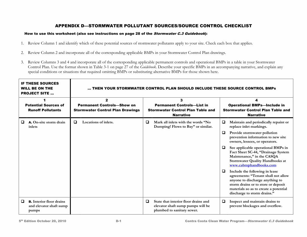
APPENDIX D—STORMWATER POLLUTANT SOURCES/SOURCE CONTROL CHECKLIST
5th Edition October 20, 2010 D-1 Contra Costa Clean Water Program—Stormwater C.3 Guidebook
How to use this worksheet (also see instructions on page 28 of the Stormwater C.3 Guidebook): 1. Review Column 1 and identify which of these potential sources of stormwater pollutants apply to your site. Check each box that applies.
2. Review Column 2 and incorporate all of the corresponding applicable BMPs in your Stormwater Control Plan drawings.
3. Review Columns 3 and 4 and incorporate all of the corresponding applicable permanent controls and operational BMPs in a table in your Stormwater Control Plan. Use the format shown in Table 3-1 on page 27 of the Guidebook. Describe your specific BMPs in an accompanying narrative, and explain any special conditions or situations that required omitting BMPs or substituting alternative BMPs for those shown here.
IF THESE SOURCES WILL BE ON THE PROJECT SITE …
… THEN YOUR STORMWATER CONTROL PLAN SHOULD INCLUDE THESE SOURCE CONTROL BMPs
1 Potential Sources of
Runoff Pollutants
2 Permanent Controls—Show on
Stormwater Control Plan Drawings
3 Permanent Controls—List in
Stormwater Control Plan Table and Narrative
4 Operational BMPs—Include in
Stormwater Control Plan Table and Narrative
A. On-site storm drain inlets
Locations of inlets. Mark all inlets with the words “No Dumping! Flows to Bay” or similar.
Maintain and periodically repaint or replace inlet markings.
Provide stormwater pollution prevention information to new site owners, lessees, or operators.
See applicable operational BMPs in Fact Sheet SC-44, “Drainage System Maintenance,” in the CASQA Stormwater Quality Handbooks at www.cabmphandbooks.com
Include the following in lease agreements: “Tenant shall not allow anyone to discharge anything to storm drains or to store or deposit materials so as to create a potential discharge to storm drains.”
B. Interior floor drains and elevator shaft sump pumps
State that interior floor drains and elevator shaft sump pumps will be plumbed to sanitary sewer.
Inspect and maintain drains to prevent blockages and overflow.
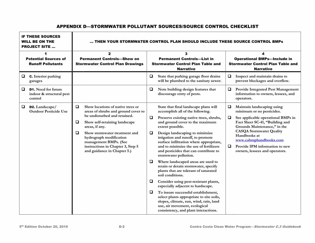
APPENDIX D—STORMWATER POLLUTANT SOURCES/SOURCE CONTROL CHECKLIST
5th Edition October 20, 2010 D-2 Contra Costa Clean Water Program—Stormwater C.3 Guidebook
IF THESE SOURCES WILL BE ON THE PROJECT SITE …
… THEN YOUR STORMWATER CONTROL PLAN SHOULD INCLUDE THESE SOURCE CONTROL BMPs
1 Potential Sources of
Runoff Pollutants
2 Permanent Controls—Show on
Stormwater Control Plan Drawings
3 Permanent Controls—List in
Stormwater Control Plan Table and Narrative
4 Operational BMPs—Include in
Stormwater Control Plan Table and Narrative
C. Interior parking garages
State that parking garage floor drains will be plumbed to the sanitary sewer.
Inspect and maintain drains to prevent blockages and overflow.
D1. Need for future indoor & structural pest control
Note building design features that discourage entry of pests.
Provide Integrated Pest Management information to owners, lessees, and operators.
D2. Landscape/ Outdoor Pesticide Use
Show locations of native trees or areas of shrubs and ground cover to be undisturbed and retained.
Show self-retaining landscape areas, if any.
Show stormwater treatment and hydrograph modification management BMPs. (See instructions in Chapter 3, Step 5 and guidance in Chapter 5.)
State that final landscape plans will accomplish all of the following.
Preserve existing native trees, shrubs, and ground cover to the maximum extent possible.
Design landscaping to minimize irrigation and runoff, to promote surface infiltration where appropriate, and to minimize the use of fertilizers and pesticides that can contribute to stormwater pollution.
Where landscaped areas are used to retain or detain stormwater, specify plants that are tolerant of saturated soil conditions.
Consider using pest-resistant plants, especially adjacent to hardscape.
To insure successful establishment, select plants appropriate to site soils, slopes, climate, sun, wind, rain, land use, air movement, ecological consistency, and plant interactions.
Maintain landscaping using minimum or no pesticides.
See applicable operational BMPs in Fact Sheet SC-41, “Building and Grounds Maintenance,” in the CASQA Stormwater Quality Handbooks at www.cabmphandbooks.com
Provide IPM information to new owners, lessees and operators.
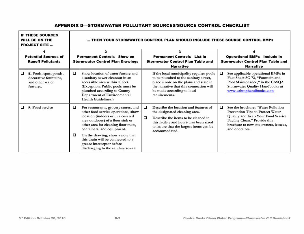
APPENDIX D—STORMWATER POLLUTANT SOURCES/SOURCE CONTROL CHECKLIST
5th Edition October 20, 2010 D-3 Contra Costa Clean Water Program—Stormwater C.3 Guidebook
IF THESE SOURCES WILL BE ON THE PROJECT SITE …
… THEN YOUR STORMWATER CONTROL PLAN SHOULD INCLUDE THESE SOURCE CONTROL BMPs
1 Potential Sources of
Runoff Pollutants
2 Permanent Controls—Show on
Stormwater Control Plan Drawings
3 Permanent Controls—List in
Stormwater Control Plan Table and Narrative
4 Operational BMPs—Include in
Stormwater Control Plan Table and Narrative
E. Pools, spas, ponds, decorative fountains, and other water features.
Show location of water feature and a sanitary sewer cleanout in an accessible area within 10 feet. (Exception: Public pools must be plumbed according to County Department of Environmental Health Guidelines.)
If the local municipality requires pools to be plumbed to the sanitary sewer, place a note on the plans and state in the narrative that this connection will be made according to local requirements.
See applicable operational BMPs in Fact Sheet SC-72, “Fountain and Pool Maintenance,” in the CASQA Stormwater Quality Handbooks at www.cabmphandbooks.com
F. Food service
For restaurants, grocery stores, and other food service operations, show location (indoors or in a covered area outdoors) of a floor sink or other area for cleaning floor mats, containers, and equipment.
On the drawing, show a note that this drain will be connected to a grease interceptor before discharging to the sanitary sewer.
Describe the location and features of the designated cleaning area.
Describe the items to be cleaned in this facility and how it has been sized to insure that the largest items can be accommodated.
See the brochure, “Water Pollution Prevention Tips to Protect Water Quality and Keep Your Food Service Facility Clean.” Provide this brochure to new site owners, lessees, and operators.
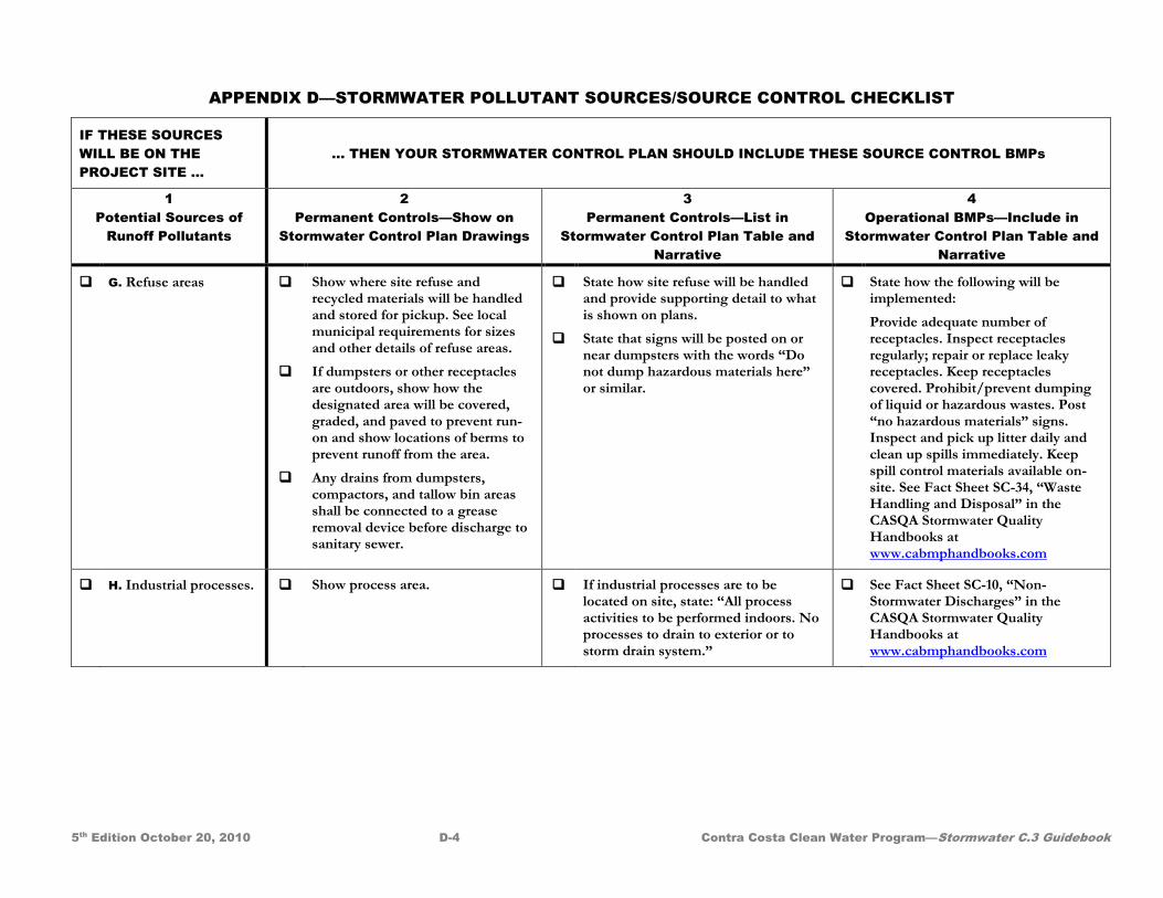
APPENDIX D—STORMWATER POLLUTANT SOURCES/SOURCE CONTROL CHECKLIST
5th Edition October 20, 2010 D-4 Contra Costa Clean Water Program—Stormwater C.3 Guidebook
IF THESE SOURCES WILL BE ON THE PROJECT SITE …
… THEN YOUR STORMWATER CONTROL PLAN SHOULD INCLUDE THESE SOURCE CONTROL BMPs
1 Potential Sources of
Runoff Pollutants
2 Permanent Controls—Show on
Stormwater Control Plan Drawings
3 Permanent Controls—List in
Stormwater Control Plan Table and Narrative
4 Operational BMPs—Include in
Stormwater Control Plan Table and Narrative
G. Refuse areas
Show where site refuse and recycled materials will be handled and stored for pickup. See local municipal requirements for sizes and other details of refuse areas.
If dumpsters or other receptacles are outdoors, show how the designated area will be covered, graded, and paved to prevent run-on and show locations of berms to prevent runoff from the area.
Any drains from dumpsters, compactors, and tallow bin areas shall be connected to a grease removal device before discharge to sanitary sewer.
State how site refuse will be handled and provide supporting detail to what is shown on plans.
State that signs will be posted on or near dumpsters with the words “Do not dump hazardous materials here” or similar.
State how the following will be implemented:
Provide adequate number of receptacles. Inspect receptacles regularly; repair or replace leaky receptacles. Keep receptacles covered. Prohibit/prevent dumping of liquid or hazardous wastes. Post “no hazardous materials” signs. Inspect and pick up litter daily and clean up spills immediately. Keep spill control materials available on-site. See Fact Sheet SC-34, “Waste Handling and Disposal” in the CASQA Stormwater Quality Handbooks at www.cabmphandbooks.com
H. Industrial processes. Show process area. If industrial processes are to be located on site, state: “All process activities to be performed indoors. No processes to drain to exterior or to storm drain system.”
See Fact Sheet SC-10, “Non-Stormwater Discharges” in the CASQA Stormwater Quality Handbooks at www.cabmphandbooks.com
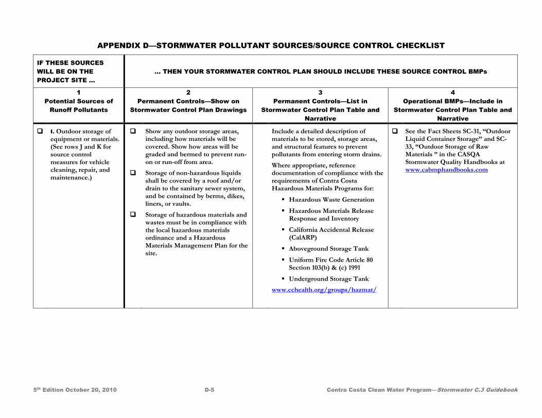
APPENDIX D—STORMWATER POLLUTANT SOURCES/SOURCE CONTROL CHECKLIST
5th Edition October 20, 2010 D-5 Contra Costa Clean Water Program—Stormwater C.3 Guidebook
IF THESE SOURCES WILL BE ON THE PROJECT SITE …
… THEN YOUR STORMWATER CONTROL PLAN SHOULD INCLUDE THESE SOURCE CONTROL BMPs
1 Potential Sources of
Runoff Pollutants
2 Permanent Controls—Show on
Stormwater Control Plan Drawings
3 Permanent Controls—List in
Stormwater Control Plan Table and Narrative
4 Operational BMPs—Include in
Stormwater Control Plan Table and Narrative
I. Outdoor storage of equipment or materials. (See rows J and K for source control measures for vehicle cleaning, repair, and maintenance.)
Show any outdoor storage areas, including how materials will be covered. Show how areas will be graded and bermed to prevent run-on or run-off from area.
Storage of non-hazardous liquids shall be covered by a roof and/or drain to the sanitary sewer system, and be contained by berms, dikes, liners, or vaults.
Storage of hazardous materials and wastes must be in compliance with the local hazardous materials ordinance and a Hazardous Materials Management Plan for the site.
Include a detailed description of materials to be stored, storage areas, and structural features to prevent pollutants from entering storm drains.
Where appropriate, reference documentation of compliance with the requirements of Contra Costa Hazardous Materials Programs for:
Hazardous Waste Generation
Hazardous Materials Release Response and Inventory
California Accidental Release (CalARP)
Aboveground Storage Tank
Uniform Fire Code Article 80 Section 103(b) & (c) 1991
Underground Storage Tank www.cchealth.org/groups/hazmat/
See the Fact Sheets SC-31, “Outdoor Liquid Container Storage” and SC-33, “Outdoor Storage of Raw Materials ” in the CASQA Stormwater Quality Handbooks at www.cabmphandbooks.com
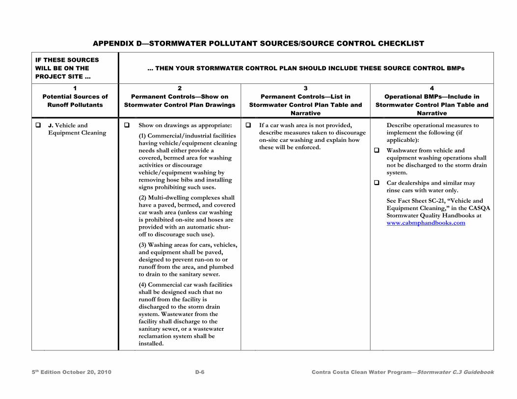
APPENDIX D—STORMWATER POLLUTANT SOURCES/SOURCE CONTROL CHECKLIST
5th Edition October 20, 2010 D-6 Contra Costa Clean Water Program—Stormwater C.3 Guidebook
IF THESE SOURCES WILL BE ON THE PROJECT SITE …
… THEN YOUR STORMWATER CONTROL PLAN SHOULD INCLUDE THESE SOURCE CONTROL BMPs
1 Potential Sources of
Runoff Pollutants
2 Permanent Controls—Show on
Stormwater Control Plan Drawings
3 Permanent Controls—List in
Stormwater Control Plan Table and Narrative
4 Operational BMPs—Include in
Stormwater Control Plan Table and Narrative
J. Vehicle and Equipment Cleaning
Show on drawings as appropriate:
(1) Commercial/industrial facilities having vehicle/equipment cleaning needs shall either provide a covered, bermed area for washing activities or discourage vehicle/equipment washing by removing hose bibs and installing signs prohibiting such uses.
(2) Multi-dwelling complexes shall have a paved, bermed, and covered car wash area (unless car washing is prohibited on-site and hoses are provided with an automatic shut-off to discourage such use).
(3) Washing areas for cars, vehicles, and equipment shall be paved, designed to prevent run-on to or runoff from the area, and plumbed to drain to the sanitary sewer.
(4) Commercial car wash facilities shall be designed such that no runoff from the facility is discharged to the storm drain system. Wastewater from the facility shall discharge to the sanitary sewer, or a wastewater reclamation system shall be installed.
If a car wash area is not provided, describe measures taken to discourage on-site car washing and explain how these will be enforced.
Describe operational measures to implement the following (if applicable):
Washwater from vehicle and equipment washing operations shall not be discharged to the storm drain system.
Car dealerships and similar may rinse cars with water only.
See Fact Sheet SC-21, “Vehicle and Equipment Cleaning,” in the CASQA Stormwater Quality Handbooks at www.cabmphandbooks.com
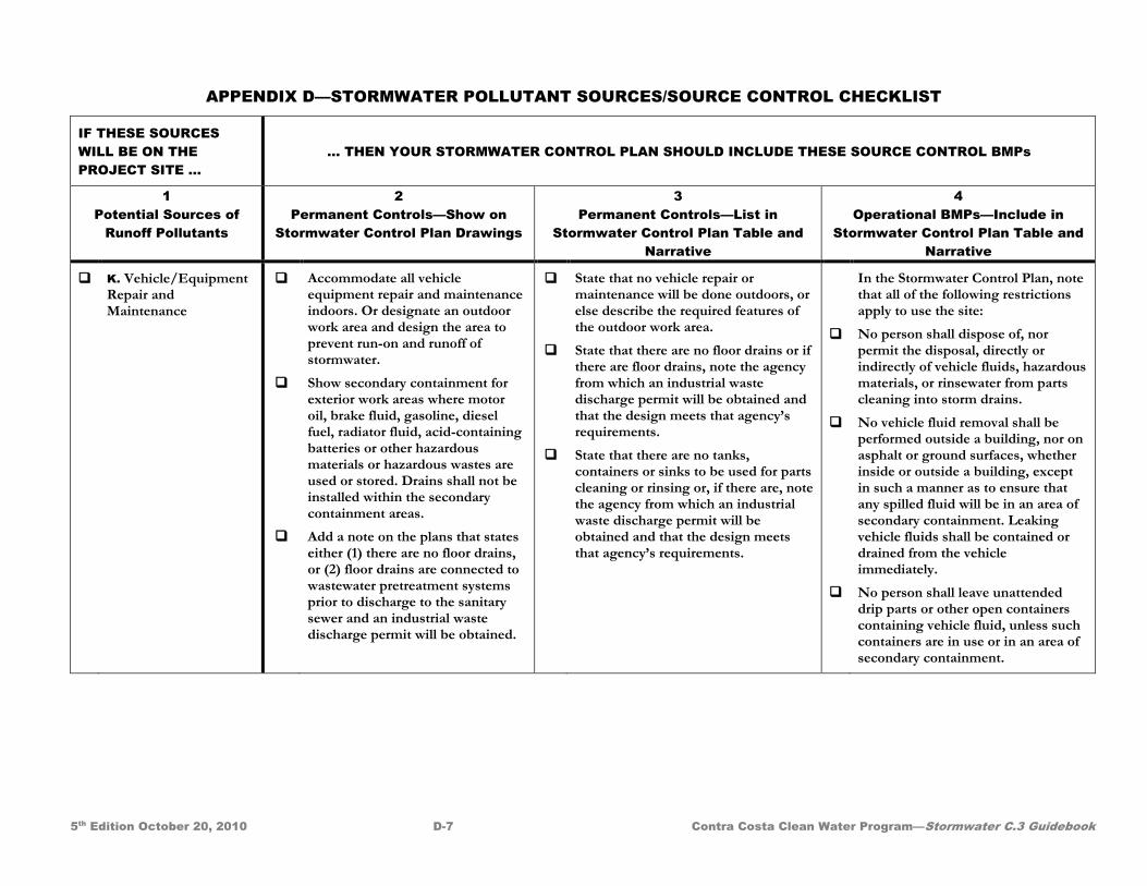
APPENDIX D—STORMWATER POLLUTANT SOURCES/SOURCE CONTROL CHECKLIST
5th Edition October 20, 2010 D-7 Contra Costa Clean Water Program—Stormwater C.3 Guidebook
IF THESE SOURCES WILL BE ON THE PROJECT SITE …
… THEN YOUR STORMWATER CONTROL PLAN SHOULD INCLUDE THESE SOURCE CONTROL BMPs
1 Potential Sources of
Runoff Pollutants
2 Permanent Controls—Show on
Stormwater Control Plan Drawings
3 Permanent Controls—List in
Stormwater Control Plan Table and Narrative
4 Operational BMPs—Include in
Stormwater Control Plan Table and Narrative
K. Vehicle/Equipment Repair and Maintenance
Accommodate all vehicle equipment repair and maintenance indoors. Or designate an outdoor work area and design the area to prevent run-on and runoff of stormwater.
Show secondary containment for exterior work areas where motor oil, brake fluid, gasoline, diesel fuel, radiator fluid, acid-containing batteries or other hazardous materials or hazardous wastes are used or stored. Drains shall not be installed within the secondary containment areas.
Add a note on the plans that states either (1) there are no floor drains, or (2) floor drains are connected to wastewater pretreatment systems prior to discharge to the sanitary sewer and an industrial waste discharge permit will be obtained.
State that no vehicle repair or maintenance will be done outdoors, or else describe the required features of the outdoor work area.
State that there are no floor drains or if there are floor drains, note the agency from which an industrial waste discharge permit will be obtained and that the design meets that agency’s requirements.
State that there are no tanks, containers or sinks to be used for parts cleaning or rinsing or, if there are, note the agency from which an industrial waste discharge permit will be obtained and that the design meets that agency’s requirements.
In the Stormwater Control Plan, note that all of the following restrictions apply to use the site:
No person shall dispose of, nor permit the disposal, directly or indirectly of vehicle fluids, hazardous materials, or rinsewater from parts cleaning into storm drains.
No vehicle fluid removal shall be performed outside a building, nor on asphalt or ground surfaces, whether inside or outside a building, except in such a manner as to ensure that any spilled fluid will be in an area of secondary containment. Leaking vehicle fluids shall be contained or drained from the vehicle immediately.
No person shall leave unattended drip parts or other open containers containing vehicle fluid, unless such containers are in use or in an area of secondary containment.

APPENDIX D—STORMWATER POLLUTANT SOURCES/SOURCE CONTROL CHECKLIST
5th Edition October 20, 2010 D-8 Contra Costa Clean Water Program—Stormwater C.3 Guidebook
IF THESE SOURCES WILL BE ON THE PROJECT SITE …
… THEN YOUR STORMWATER CONTROL PLAN SHOULD INCLUDE THESE SOURCE CONTROL BMPs
1 Potential Sources of
Runoff Pollutants
2 Permanent Controls—Show on
Stormwater Control Plan Drawings
3 Permanent Controls—List in
Stormwater Control Plan Table and Narrative
4 Operational BMPs—Include in
Stormwater Control Plan Table and Narrative
L. Fuel Dispensing Areas
Fueling areas1
Fueling areas shall be covered by a canopy that extends a minimum of ten feet in each direction from each pump. [Alternative: The fueling area must be covered and the cover’s minimum dimensions must be equal to or greater than the area within the grade break or fuel dispensing area1.] The canopy [or cover] shall not drain onto the fueling area.
shall have impermeable floors (i.e., portland cement concrete or equivalent smooth impervious surface) that are: a) graded at the minimum slope necessary to prevent ponding; and b) separated from the rest of the site by a grade break that prevents run-on of stormwater to the maximum extent practicable.
The property owner shall dry sweep the fueling area routinely.
See the Business Guide Sheet, “Automotive Service—Service Stations” in the CASQA Stormwater Quality Handbooks at www.cabmphandbooks.com
1 The fueling area shall be defined as the area extending a minimum of 6.5 feet from the corner of each fuel dispenser or the length at which the hose and nozzle assembly may be operated plus a minimum of one foot, whichever is greater.
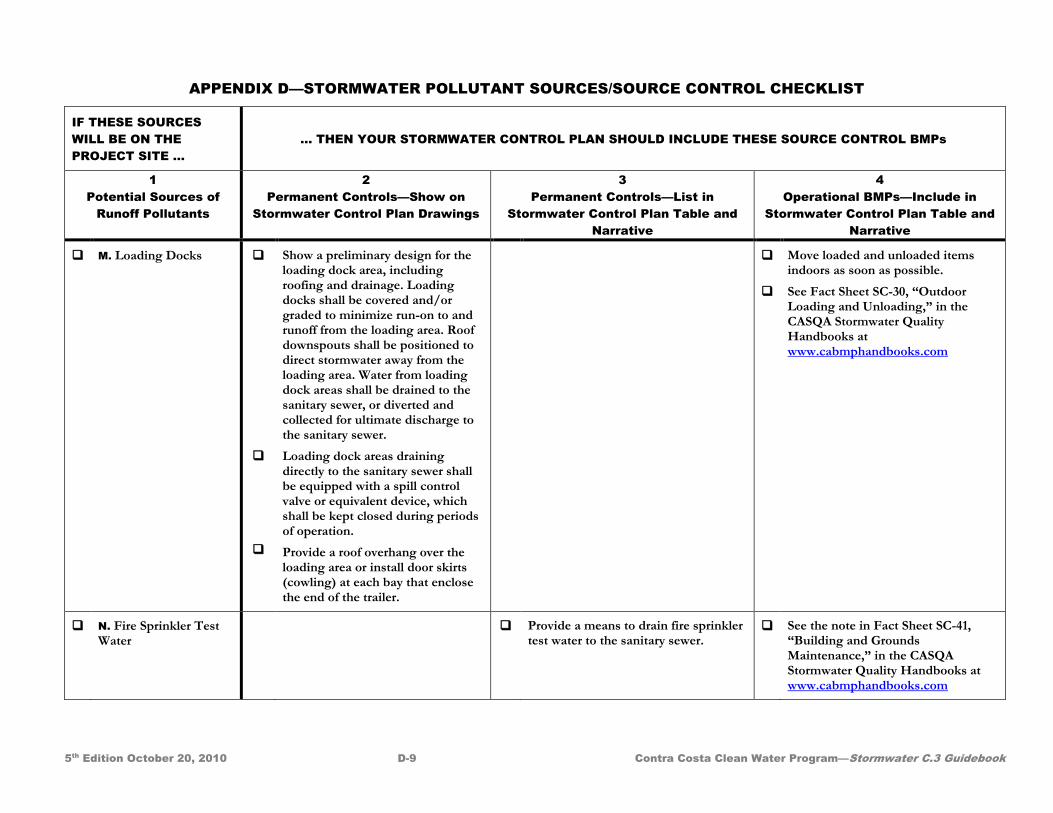
APPENDIX D—STORMWATER POLLUTANT SOURCES/SOURCE CONTROL CHECKLIST
5th Edition October 20, 2010 D-9 Contra Costa Clean Water Program—Stormwater C.3 Guidebook
IF THESE SOURCES WILL BE ON THE PROJECT SITE …
… THEN YOUR STORMWATER CONTROL PLAN SHOULD INCLUDE THESE SOURCE CONTROL BMPs
1 Potential Sources of
Runoff Pollutants
2 Permanent Controls—Show on
Stormwater Control Plan Drawings
3 Permanent Controls—List in
Stormwater Control Plan Table and Narrative
4 Operational BMPs—Include in
Stormwater Control Plan Table and Narrative
M. Loading Docks
Show a preliminary design for the loading dock area, including roofing and drainage. Loading docks shall be covered and/or graded to minimize run-on to and runoff from the loading area. Roof downspouts shall be positioned to direct stormwater away from the loading area. Water from loading dock areas shall be drained to the sanitary sewer, or diverted and collected for ultimate discharge to the sanitary sewer.
Loading dock areas draining directly to the sanitary sewer shall be equipped with a spill control valve or equivalent device, which shall be kept closed during periods of operation.
Provide a roof overhang over the loading area or install door skirts (cowling) at each bay that enclose the end of the trailer.
Move loaded and unloaded items indoors as soon as possible.
See Fact Sheet SC-30, “Outdoor Loading and Unloading,” in the CASQA Stormwater Quality Handbooks at www.cabmphandbooks.com
N. Fire Sprinkler Test Water
Provide a means to drain fire sprinkler test water to the sanitary sewer.
See the note in Fact Sheet SC-41, “Building and Grounds Maintenance,” in the CASQA Stormwater Quality Handbooks at www.cabmphandbooks.com
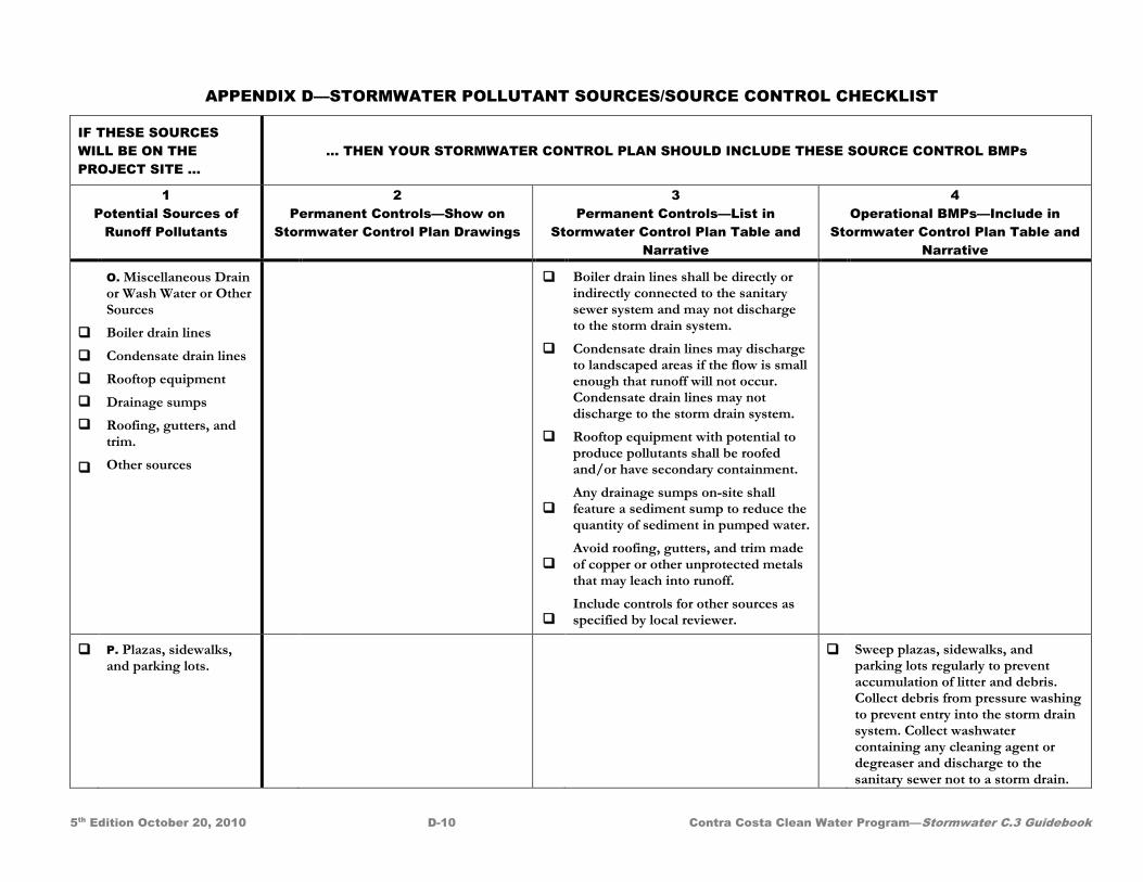
APPENDIX D—STORMWATER POLLUTANT SOURCES/SOURCE CONTROL CHECKLIST
5th Edition October 20, 2010 D-10 Contra Costa Clean Water Program—Stormwater C.3 Guidebook
IF THESE SOURCES WILL BE ON THE PROJECT SITE …
… THEN YOUR STORMWATER CONTROL PLAN SHOULD INCLUDE THESE SOURCE CONTROL BMPs
1 Potential Sources of
Runoff Pollutants
2 Permanent Controls—Show on
Stormwater Control Plan Drawings
3 Permanent Controls—List in
Stormwater Control Plan Table and Narrative
4 Operational BMPs—Include in
Stormwater Control Plan Table and Narrative
O. Miscellaneous Drain or Wash Water or Other Sources
Boiler drain lines
Condensate drain lines
Rooftop equipment
Drainage sumps
Roofing, gutters, and trim.
Other sources
Boiler drain lines shall be directly or indirectly connected to the sanitary sewer system and may not discharge to the storm drain system.
Condensate drain lines may discharge to landscaped areas if the flow is small enough that runoff will not occur. Condensate drain lines may not discharge to the storm drain system.
Rooftop equipment with potential to produce pollutants shall be roofed and/or have secondary containment.
Any drainage sumps on-site shall feature a sediment sump to reduce the quantity of sediment in pumped water.
Avoid roofing, gutters, and trim made of copper or other unprotected metals that may leach into runoff.
Include controls for other sources as specified by local reviewer.
P. Plazas, sidewalks, and parking lots.
Sweep plazas, sidewalks, and parking lots regularly to prevent accumulation of litter and debris. Collect debris from pressure washing to prevent entry into the storm drain system. Collect washwater containing any cleaning agent or degreaser and discharge to the sanitary sewer not to a storm drain.