Embed Size (px)
DESCRIPTION
storm drain design
Citation preview
Revised January 2006
CITY AND COUNTY OF DENVER
STORM DRAINAGE DESIGN& TECHNICAL CRITERIA
Department of Public WorksWastewater Management Division
Engineering Division

This page intentionally left blank.
STORM DRAINAGE DESIGN AND TECHNICAL CRITERIA PREFACE
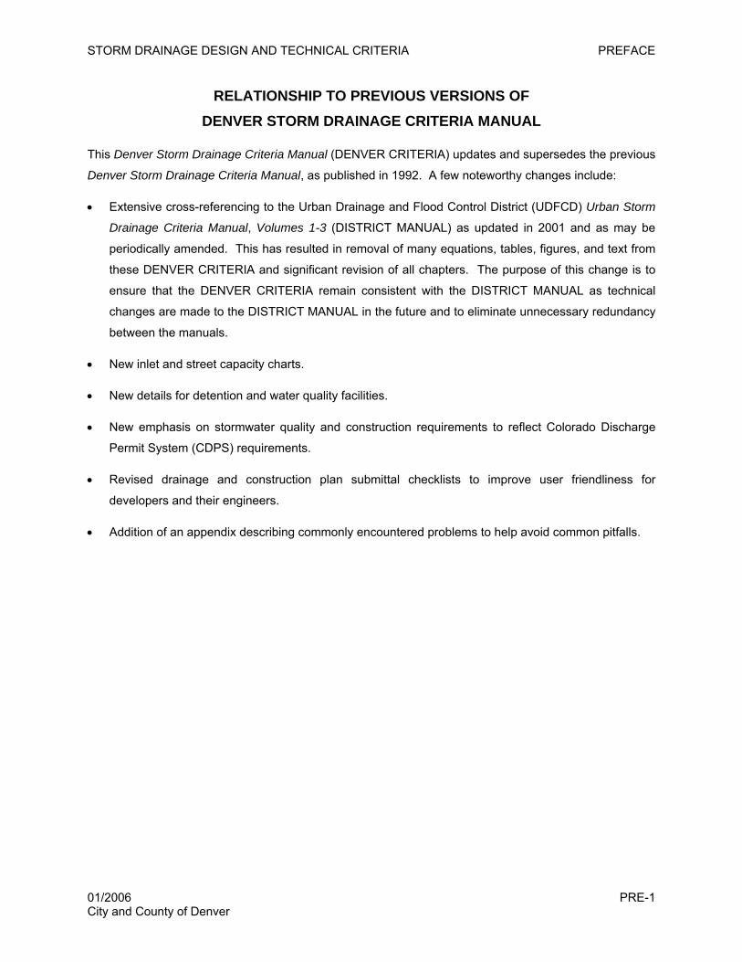
RELATIONSHIP TO PREVIOUS VERSIONS OF DENVER STORM DRAINAGE CRITERIA MANUAL
This Denver Storm Drainage Criteria Manual (DENVER CRITERIA) updates and supersedes the previous
Denver Storm Drainage Criteria Manual, as published in 1992. A few noteworthy changes include:
• Extensive cross-referencing to the Urban Drainage and Flood Control District (UDFCD) Urban Storm
Drainage Criteria Manual, Volumes 1-3 (DISTRICT MANUAL) as updated in 2001 and as may be
periodically amended. This has resulted in removal of many equations, tables, figures, and text from
these DENVER CRITERIA and significant revision of all chapters. The purpose of this change is to
ensure that the DENVER CRITERIA remain consistent with the DISTRICT MANUAL as technical
changes are made to the DISTRICT MANUAL in the future and to eliminate unnecessary redundancy
between the manuals.
• New inlet and street capacity charts.
• New details for detention and water quality facilities.
• New emphasis on stormwater quality and construction requirements to reflect Colorado Discharge
Permit System (CDPS) requirements.
• Revised drainage and construction plan submittal checklists to improve user friendliness for
developers and their engineers.
• Addition of an appendix describing commonly encountered problems to help avoid common pitfalls.
01/2006 PRE-1 City and County of Denver

STORM DRAINAGE DESIGN AND TECHNICAL CRITERIA PREFACE
This page intentionally left blank.
01/2006 PRE-2 City and County of Denver
STORM DRAINAGE DESIGN AND TECHNICAL CRITERIA PREFACE
ACKNOWLEDGEMENTS
The City and County of Denver acknowledges and thanks the following individuals and organizations for
their contributions to this manual.
Denver Public Works Department
Saeed Farahmandi, P.E., Co-project Director
Ted Christianson, P.E.
Alan Sorrel, P.E.
Lynn Brown-Jones
Terry Baus, P.E.
Kevin Lewis, P.E.
Dave Stever
Urban Drainage and Flood Control District
Ben Urbonas, P.E., Co-project Director
Ken Mackenzie, P.E., Project Engineer
Wright Water Engineers, Inc., Consultant Team
Jonathan Jones, P.E., Project Manager
Jane Clary, Project Coordinator/Technical Editor
T. Andrew Earles, P.E., Ph.D.
David W. Foss, P.E.
Kurt Loptien, Drafting
Joe J. Nye, P.E.
James C.Y. Guo, P.E., Ph.D.
This manual relies significantly on work previously completed by others in several existing storm drainage
manuals including:
Urban Storm Drainage Criteria Manual, Volumes 1-3 (UDFCD 1999, 2001)
Denver Water Quality Management Plan (WWE et al. 2004)
Draft Arapahoe County Storm Drainage Criteria Manual (Muller Engineering 2005)
Draft Douglas County Storm Drainage Criteria Manual (Muller Engineering 2005)
01/2006 PRE-3 City and County of Denver

STORM DRAINAGE DESIGN AND TECHNICAL CRITERIA PREFACE
This page intentionally left blank.
01/2006 PRE-4 City and County of Denver

STORM DRAINAGE DESIGN AND TECHNICAL CRITERIA PREFACE
ACRONYMS
BMP Best Management Practice
CAP Corrugated Aluminum Pipe
CASDP Construction Activities Stormwater Discharge Permit
CASMP Construction Activities Stormwater Management Plan
CDOT Colorado Department of Transportation
CDPS Colorado Discharge Permit System
cfs cubic feet per second
CDPHE Colorado Department of Public Health and Environment
CLOMR Conditional Letter of Map Revision
CMP Corrugated Metal Pipe
CUHP Colorado Urban Hydrograph Procedure
CWCB Colorado Water Conservation Board
EGL Energy Grade Line
FEMA Federal Emergency Management Agency
FHAD Flood Hazard Area Delineation
FHWA Federal Highway Administration
FIRM Flood Insurance Rate Map
ft feet
ft/sec feet per second
HGL Hydraulic Grade Line
IBC International Building Code
in inches
LID Low Impact Development
LOMR Letter of Map Revision
MS4 Municipal Separate Storm Sewer System
NOAA National Oceanic and Atmospheric Administration
NRCS Natural Resources Conservation Service
RCP Reinforced Concrete Pipe
ROW Right-of-Way
SEO State Engineer’s Office
SWMM Stormwater Management Model
SWMP Stormwater Management Plan
UDFCD Urban Drainage and Flood Control District
WQCV Water Quality Capture Volume
01/2006 PRE-5 City and County of Denver

STORM DRAINAGE DESIGN AND TECHNICAL CRITERIA PREFACE
This page intentionally left blank.
01/2006 PRE-6 City and County of Denver
STORM DRAINAGE DESIGN AND TECHNICAL CRITERIA TABLE OF CONTENTS
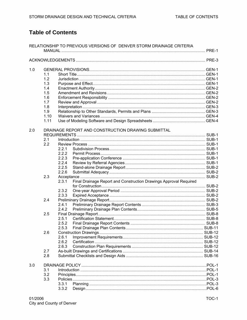
Table of Contents
RELATIONSHIP TO PREVIOUS VERSIONS OF DENVER STORM DRAINAGE CRITERIA MANUAL ................................................................................................................................. PRE-1
ACKNOWLEDGEMENTS .................................................................................................................... PRE-3
1.0 GENERAL PROVISIONS........................................................................................................ GEN-1 1.1 Short Title................................................................................................................... GEN-1 1.2 Jurisdiction ................................................................................................................. GEN-1 1.3 Purpose and Effect..................................................................................................... GEN-1 1.4 Enactment Authority................................................................................................... GEN-2 1.5 Amendment and Revisions ........................................................................................ GEN-2 1.6 Enforcement Responsibility ....................................................................................... GEN-2 1.7 Review and Approval ................................................................................................. GEN-2 1.8 Interpretation .............................................................................................................. GEN-3 1.9 Relationship to Other Standards, Permits and Plans ................................................ GEN-3 1.10 Waivers and Variances .............................................................................................. GEN-4 1.11 Use of Modeling Software and Design Spreadsheets ............................................... GEN-4
2.0 DRAINAGE REPORT AND CONSTRUCTION DRAWING SUBMITTAL REQUIREMENTS ................................................................................................................... SUB-1 2.1 Introduction ................................................................................................................ SUB-1 2.2 Review Process ......................................................................................................... SUB-1
2.2.1 Subdivision Process...................................................................................... SUB-1 2.2.2 Permit Process.............................................................................................. SUB-1 2.2.3 Pre-application Conference .......................................................................... SUB-1 2.2.4 Review by Referral Agencies........................................................................ SUB-1 2.2.5 Stand-alone Drainage Report ....................................................................... SUB-2 2.2.6 Submittal Adequacy ...................................................................................... SUB-2
2.3 Acceptance ................................................................................................................ SUB-2 2.3.1 Final Drainage Report and Construction Drawings Approval Required
for Construction............................................................................................. SUB-2 2.3.2 One-year Approval Period ............................................................................ SUB-2 2.3.3 Expired Acceptance ...................................................................................... SUB-2
2.4 Preliminary Drainage Report...................................................................................... SUB-2 2.4.1 Preliminary Drainage Report Contents ......................................................... SUB-3 2.4.2 Preliminary Drainage Plan Contents............................................................. SUB-5
2.5 Final Drainage Report ................................................................................................ SUB-8 2.5.1 Certification Statement.................................................................................. SUB-8 2.5.2 Final Drainage Report Contents ................................................................... SUB-8 2.5.3 Final Drainage Plan Contents ..................................................................... SUB-11
2.6 Construction Drawings............................................................................................. SUB-12 2.6.1 Improvement Requirements........................................................................ SUB-12 2.6.2 Certification ................................................................................................. SUB-12 2.6.3 Construction Plan Requirements ................................................................ SUB-12
2.7 As-built Drawings and Certifications ........................................................................ SUB-14 2.8 Submittal Checklists and Design Aids ..................................................................... SUB-16
3.0 DRAINAGE POLICY ................................................................................................................POL-1 3.1 Introduction .................................................................................................................POL-1 3.2 Principles.....................................................................................................................POL-1 3.3 Policies........................................................................................................................POL-3
3.3.1 Planning .........................................................................................................POL-3 3.3.2 Design ............................................................................................................POL-6
01/2006 TOC-1 City and County of Denver
STORM DRAINAGE DESIGN AND TECHNICAL CRITERIA TABLE OF CONTENTS
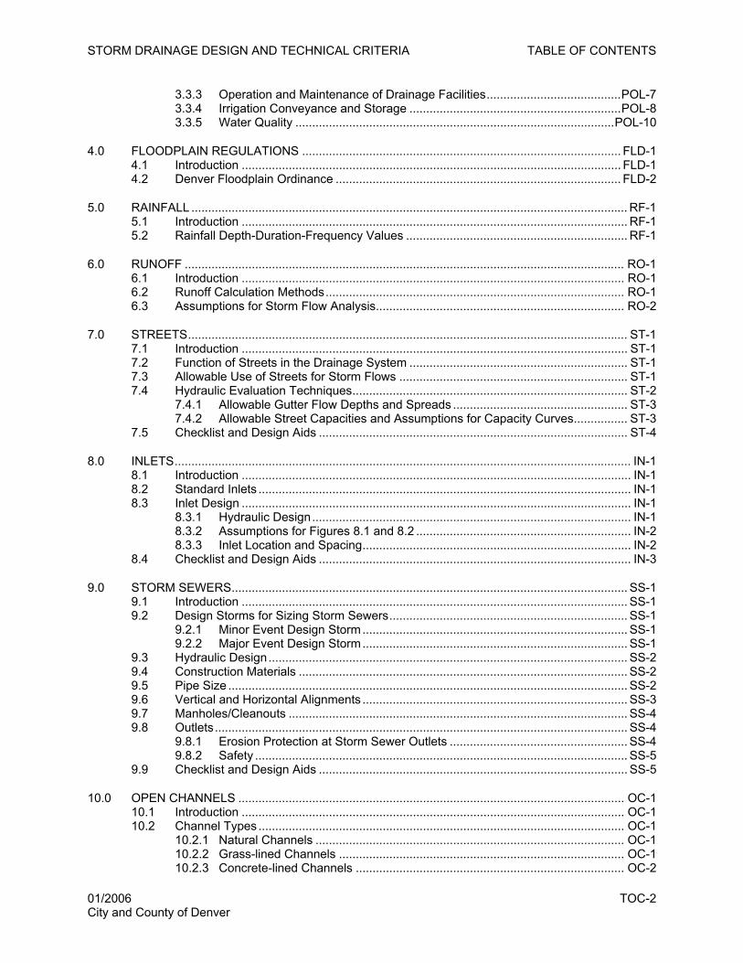
3.3.3 Operation and Maintenance of Drainage Facilities........................................POL-7 3.3.4 Irrigation Conveyance and Storage ...............................................................POL-8 3.3.5 Water Quality ...............................................................................................POL-10
4.0 FLOODPLAIN REGULATIONS ............................................................................................... FLD-1 4.1 Introduction ................................................................................................................. FLD-1 4.2 Denver Floodplain Ordinance ..................................................................................... FLD-2
5.0 RAINFALL .................................................................................................................................. RF-1 5.1 Introduction ................................................................................................................... RF-1 5.2 Rainfall Depth-Duration-Frequency Values .................................................................. RF-1
6.0 RUNOFF ................................................................................................................................... RO-1 6.1 Introduction .................................................................................................................. RO-1 6.2 Runoff Calculation Methods......................................................................................... RO-1 6.3 Assumptions for Storm Flow Analysis.......................................................................... RO-2
7.0 STREETS................................................................................................................................... ST-1 7.1 Introduction ................................................................................................................... ST-1 7.2 Function of Streets in the Drainage System ................................................................. ST-1 7.3 Allowable Use of Streets for Storm Flows .................................................................... ST-1 7.4 Hydraulic Evaluation Techniques.................................................................................. ST-2
7.4.1 Allowable Gutter Flow Depths and Spreads .................................................... ST-3 7.4.2 Allowable Street Capacities and Assumptions for Capacity Curves................ ST-3
7.5 Checklist and Design Aids ............................................................................................ ST-4
8.0 INLETS........................................................................................................................................ IN-1 8.1 Introduction .................................................................................................................... IN-1 8.2 Standard Inlets ............................................................................................................... IN-1 8.3 Inlet Design .................................................................................................................... IN-1
8.3.1 Hydraulic Design............................................................................................... IN-1 8.3.2 Assumptions for Figures 8.1 and 8.2 ................................................................ IN-2 8.3.3 Inlet Location and Spacing................................................................................ IN-2
8.4 Checklist and Design Aids ............................................................................................. IN-3
9.0 STORM SEWERS...................................................................................................................... SS-1 9.1 Introduction ................................................................................................................... SS-1 9.2 Design Storms for Sizing Storm Sewers....................................................................... SS-1
9.2.1 Minor Event Design Storm............................................................................... SS-1 9.2.2 Major Event Design Storm............................................................................... SS-1
9.3 Hydraulic Design........................................................................................................... SS-2 9.4 Construction Materials .................................................................................................. SS-2 9.5 Pipe Size ....................................................................................................................... SS-2 9.6 Vertical and Horizontal Alignments ............................................................................... SS-3 9.7 Manholes/Cleanouts ..................................................................................................... SS-4 9.8 Outlets........................................................................................................................... SS-4
9.8.1 Erosion Protection at Storm Sewer Outlets ..................................................... SS-4 9.8.2 Safety ............................................................................................................... SS-5
9.9 Checklist and Design Aids ............................................................................................ SS-5
10.0 OPEN CHANNELS ................................................................................................................... OC-1 10.1 Introduction .................................................................................................................. OC-1 10.2 Channel Types ............................................................................................................. OC-1
10.2.1 Natural Channels ............................................................................................ OC-1 10.2.2 Grass-lined Channels ..................................................................................... OC-1 10.2.3 Concrete-lined Channels ................................................................................ OC-2
01/2006 TOC-2 City and County of Denver
STORM DRAINAGE DESIGN AND TECHNICAL CRITERIA TABLE OF CONTENTS
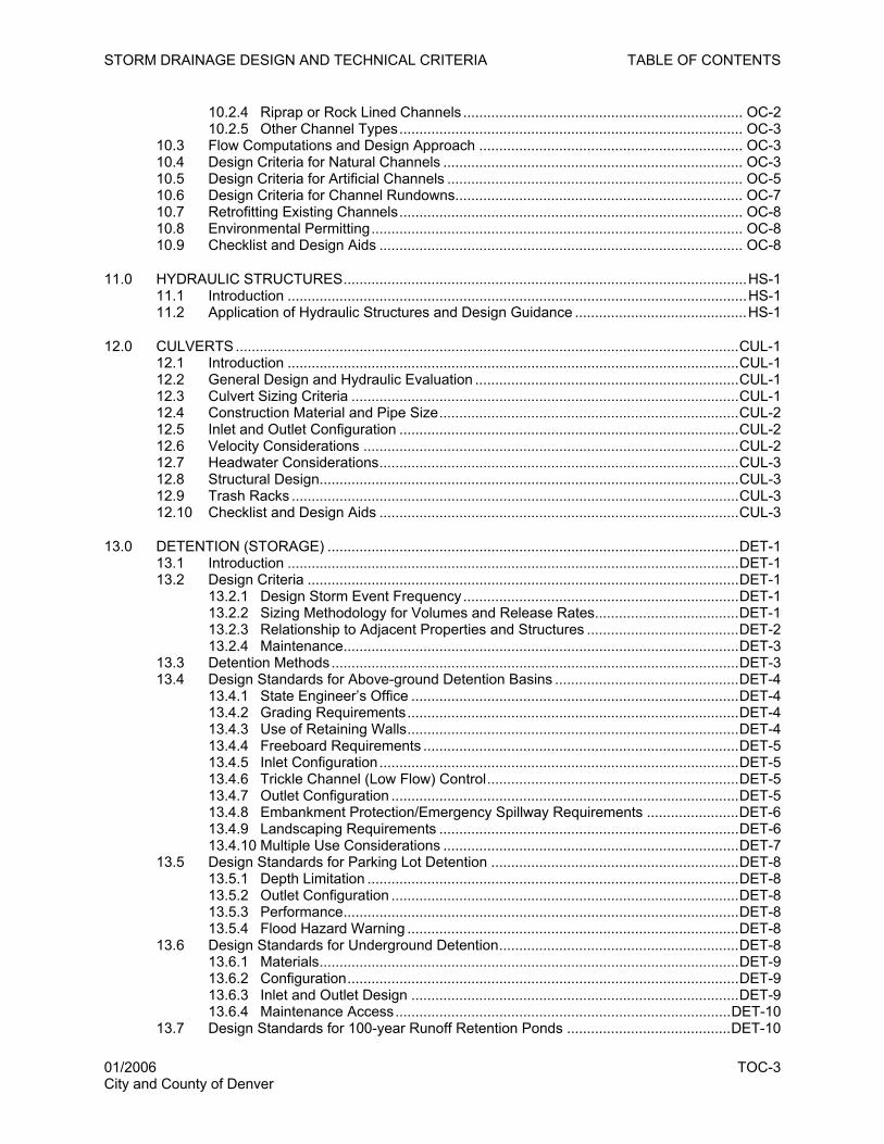
10.2.4 Riprap or Rock Lined Channels ...................................................................... OC-2 10.2.5 Other Channel Types...................................................................................... OC-3
10.3 Flow Computations and Design Approach .................................................................. OC-3 10.4 Design Criteria for Natural Channels ........................................................................... OC-3 10.5 Design Criteria for Artificial Channels .......................................................................... OC-5 10.6 Design Criteria for Channel Rundowns........................................................................ OC-7 10.7 Retrofitting Existing Channels...................................................................................... OC-8 10.8 Environmental Permitting............................................................................................. OC-8 10.9 Checklist and Design Aids ........................................................................................... OC-8
11.0 HYDRAULIC STRUCTURES.....................................................................................................HS-1 11.1 Introduction ...................................................................................................................HS-1 11.2 Application of Hydraulic Structures and Design Guidance ...........................................HS-1
12.0 CULVERTS ..............................................................................................................................CUL-1 12.1 Introduction .................................................................................................................CUL-1 12.2 General Design and Hydraulic Evaluation ..................................................................CUL-1 12.3 Culvert Sizing Criteria .................................................................................................CUL-1 12.4 Construction Material and Pipe Size...........................................................................CUL-2 12.5 Inlet and Outlet Configuration .....................................................................................CUL-2 12.6 Velocity Considerations ..............................................................................................CUL-2 12.7 Headwater Considerations..........................................................................................CUL-3 12.8 Structural Design.........................................................................................................CUL-3 12.9 Trash Racks ................................................................................................................CUL-3 12.10 Checklist and Design Aids ..........................................................................................CUL-3
13.0 DETENTION (STORAGE) .......................................................................................................DET-1 13.1 Introduction .................................................................................................................DET-1 13.2 Design Criteria ............................................................................................................DET-1
13.2.1 Design Storm Event Frequency.....................................................................DET-1 13.2.2 Sizing Methodology for Volumes and Release Rates....................................DET-1 13.2.3 Relationship to Adjacent Properties and Structures ......................................DET-2 13.2.4 Maintenance...................................................................................................DET-3
13.3 Detention Methods......................................................................................................DET-3 13.4 Design Standards for Above-ground Detention Basins ..............................................DET-4
13.4.1 State Engineer’s Office ..................................................................................DET-4 13.4.2 Grading Requirements...................................................................................DET-4 13.4.3 Use of Retaining Walls...................................................................................DET-4 13.4.4 Freeboard Requirements ...............................................................................DET-5 13.4.5 Inlet Configuration..........................................................................................DET-5 13.4.6 Trickle Channel (Low Flow) Control...............................................................DET-5 13.4.7 Outlet Configuration .......................................................................................DET-5 13.4.8 Embankment Protection/Emergency Spillway Requirements .......................DET-6 13.4.9 Landscaping Requirements ...........................................................................DET-6 13.4.10 Multiple Use Considerations ..........................................................................DET-7
13.5 Design Standards for Parking Lot Detention ..............................................................DET-8 13.5.1 Depth Limitation .............................................................................................DET-8 13.5.2 Outlet Configuration .......................................................................................DET-8 13.5.3 Performance...................................................................................................DET-8 13.5.4 Flood Hazard Warning ...................................................................................DET-8
13.6 Design Standards for Underground Detention............................................................DET-8 13.6.1 Materials.........................................................................................................DET-9 13.6.2 Configuration..................................................................................................DET-9 13.6.3 Inlet and Outlet Design ..................................................................................DET-9 13.6.4 Maintenance Access....................................................................................DET-10
13.7 Design Standards for 100-year Runoff Retention Ponds .........................................DET-10
01/2006 TOC-3 City and County of Denver
STORM DRAINAGE DESIGN AND TECHNICAL CRITERIA TABLE OF CONTENTS
13.7.1 Allowable Use ..............................................................................................DET-10 13.7.2 Calculation of Retention Volume..................................................................DET-10 13.7.3 Design Standards for Retention Ponds .......................................................DET-11
13.8 Checklist and Design Aids ........................................................................................DET-13
14.0 WATER QUALITY.....................................................................................................................WQ-1 14.1 Introduction ..................................................................................................................WQ-1 14.2 Applicability Criteria......................................................................................................WQ-1 14.3 Minimum Technical Standards.....................................................................................WQ-2 14.4 BMP Selection..............................................................................................................WQ-3 14.5 Basic Design Principles and Procedure.......................................................................WQ-6 14.6 Maintenance.................................................................................................................WQ-8 14.7 Checklist and Design Aids ...........................................................................................WQ-8
15.0 CONSTRUCTION SITE STORMWATER MANAGEMENT AND EROSION CONTROL....... ESC-1 15.1 Introduction ................................................................................................................ ESC-1 15.2 Permit Triggers........................................................................................................... ESC-1 15.3 Basis of Site Size Determination................................................................................ ESC-2 15.4 Technical and Regulatory Standards......................................................................... ESC-2 15.5 Principles and Performance Standards ..................................................................... ESC-3 15.6 Commonly Observed Problems at Construction Sites............................................... ESC-5 15.7 Submittal Requirements............................................................................................. ESC-6 15.8 Checklist and Design Aids ......................................................................................... ESC-6
16.0 REFERENCES.........................................................................................................................REF-1 16.1 Primary References ....................................................................................................REF-1 16.2 Supplemental References...........................................................................................REF-1
APPENDIX A. STANDARD FORMS................................................................................................ APP A-1 Standard Form SF-1. Time of Concentration...................................................................... APP A-1 Standard Form SF-2. Storm Drainage System Design (Rational Method Procedure) ....... APP A-2
APPENDIX B. COMMONLY OBSERVED PROBLEMS IN DENVER DRAINAGE PROJECTS ..... APP B-1Planning ............................................................................................................................... APP B-1 General Drainage and Flooding........................................................................................... APP B-1 Public Safety ........................................................................................................................ APP B-2 Streets, Inlets and Storm Sewers ........................................................................................ APP B-2 Detention and Water Quality................................................................................................ APP B-3 Construction Sites ................................................................................................................ APP B-7
01/2006 TOC-4 City and County of Denver
STORM DRAINAGE DESIGN AND TECHNICAL CRITERIA TABLE OF CONTENTS
Tables
Table 2.1. Drawing Symbol Criteria and Hydrology Review Table..................................................... SUB-7 Table 2.2. Detention Basin Summary Table to be Placed on Drainage and Construction Plan......... SUB-7 Table 2.3. Drainage Report Checklist ............................................................................................... SUB-16 Table 2.4. Drainage Plan Checklist................................................................................................... SUB-18 Table 2.5. Construction Plan Checklist ............................................................................................. SUB-19 Table 3.1. Design Storms for the Minor and Major Systems .............................................................. POL-6 Table 3.2. Required Maintenance Easements for Drainage Facilities................................................ POL-8 Table 5.1. One Hour Point Rainfall Depths............................................................................................RF-1 Table 5.2. Calculation of Rainfall Durations Less than One Hour .........................................................RF-2 Table 5.3. Rainfall Intensity Duration Values for Use with the Rational Method ...................................RF-3 Table 6.1. Runoff Calculation Methods Acceptable for Use in Denver................................................. RO-2 Table 6.2. Assumptions for Onsite and Offsite Storm Flow Analysis in Denver ................................... RO-3 Table 7.1. Allowable Use of Streets for Minor Storm Runoff ................................................................. ST-2 Table 7.2. Allowable Use of Streets for Major Storm Runoff ................................................................. ST-2 Table 7.3. Allowable Cross-street Flow When Cross Pans Are Allowed............................................... ST-2 Table 7.4. Permitted Flow Depths for Minor Storm for 6-inch Curb and 2-percent Cross Slope........... ST-3 Table 8.1. Inlet Types.............................................................................................................................. IN-1 Table 9.1. Public Storm Sewer Size Criteria..........................................................................................SS-3 Table 9.2. Vertical Alignment Requirements for Storm Sewers.............................................................SS-3 Table 9.3. Manhole Sizes for Straight Sewers.......................................................................................SS-4 Table 9.4. Erosion Protection at Conduit Outlets...................................................................................SS-5 Table 10.1. Channel Rundown Design Criteria...................................................................................... OC-7 Table 11.1. Summary of Hydraulic Structure Types and Criteria. .........................................................HS-2 Table 12.1. Allowable Roadway Overtopping at Culvert Crossings ................................................... CUL-2 Table 12.2. Allowable Velocities at Culvert Outlets ............................................................................ CUL-3 Table 13.1. Detention Sizing Methodologies ...................................................................................... DET-2 Table 13.2. Maximum Allowable Unit Flow Release Rates (cfs/acre) per Tributary Area.................. DET-2 Table 13.3. Grading Criteria for Embankments .................................................................................. DET-4 Table 13.4 Required Retention Rainfall ............................................................................................ DET-11 Table 14.1. Permanent Stormwater BMP Requirements......................................................................WQ-2 Table 14.2. Development Type Summary ............................................................................................WQ-4 Table 14.3. BMP Applicability Matrix ....................................................................................................WQ-5 Figures
Figure 7.1. Allowable Street Capacity for Minor and Major Events ....................................................... ST-5 Figure 7.2. Reduction Factors for Gutter Flow....................................................................................... ST-6 Figure 8.1. Allowable Inlet Capacity— Sump Conditions ....................................................................... IN-4 Figure 8.2. Allowable Inlet Capacity—On Grade Conditions .................................................................. IN-5 Figure 8.3. Inlet Placement at Intersections............................................................................................ IN-6 Figure 9.1. Hydraulic Properties of Circular Pipe...................................................................................SS-7 Figure 13.1. Pond Forebay with Dissipator....................................................................................... DET-14 Figure 13.2. Concrete Trickle Channel Sections for Detention Basins............................................. DET-15 Figure 13.3. Typical Detention Outlet Structure................................................................................ DET-16 Figure 13.4. Outlet for Small On-site Detention Basin...................................................................... DET-17 Figure 13.5. Curb and Gutter Outlet Grate ....................................................................................... DET-18 Figure 13.6. Underground Detention Schematic .............................................................................. DET-19 Figure 14.1. Porous Landscape Detention ........................................................................................ WQ-10 Figure 14.2. Sand Filter Details for Use on Small Sites ≤ 1 Acre ...................................................... WQ-11
01/2006 TOC-5 City and County of Denver
STORM DRAINAGE DESIGN AND TECHNICAL CRITERIA TABLE OF CONTENTS
This page intentionally left blank.
01/2006 TOC-6 City and County of Denver
STORM DRAINAGE DESIGN AND TECHNICAL CRITERIA GENERAL PROVISIONS
1.0 GENERAL PROVISIONS
1.1 Short Title
This manual, together with all future changes and amendments, shall be known as the City and County of
Denver Storm Drainage Design and Technical Criteria Manual (hereafter called DENVER CRITERIA) as
referenced in the Public Works Rules and Regulations Governing Sewerage Charges and Fees and
Management of Wastewater (hereafter called DENVER RULES and REGULATIONS).
1.2 Jurisdiction
These DENVER CRITERIA shall apply to all land within the incorporated areas of the City and County of
Denver (Denver), including any public lands. These DENVER CRITERIA shall apply to all facilities
constructed on Denver rights-of-way (ROW), easements dedicated for public use, and to all privately
owned and maintained drainage facilities, including, but not limited to, detention facilities, storm sewers,
inlets, manholes, culverts, swales, and channels; or as otherwise approved.
1.3 Purpose and Effect
The purpose of these DENVER CRITERIA is to provide requirements and guidance necessary for
developers, consultants, and industrial and commercial operators to select, design and maintain drainage
and flood control facilities. The ultimate goal of these DENVER CRITERIA is to protect the public health,
safety and welfare and minimize adverse impacts to the environment.
Presented in these DENVER CRITERIA are the minimum design and technical criteria for the analysis
and design of storm drainage facilities for both quantity and quality during and following construction. All
new development or redevelopment projects, construction or grading projects, demolition, or any
disturbance of existing ground surface shall comply with these DENVER CRITERIA. Hereinafter, such
projects are referred to as “development and redevelopment.” All such projects submitted for approval
under the provisions of the DENVER RULES and REGULATIONS shall provide adequate analysis and
design of drainage systems for both water quantity and water quality during and following construction in
accordance with these DENVER CRITERIA. Implementing facilities that go beyond the minimum is
encouraged.
The applicant may suggest alternatives to the provisions of these DENVER CRITERIA. The applicant
shall have the burden of showing that the alternatives are equal or better. Policies and technical criteria
not specifically addressed in these DENVER CRITERIA shall follow the latest provisions of the Urban
Drainage and Flood Control District (UDFCD) Urban Storm Drainage Criteria Manual (hereinafter called
DISTRICT MANUAL). Drainage facilities in place or under construction at the time of DENVER
CRITERIA adoption shall be accepted without regard to the provisions of these DENVER CRITERIA.
01/2006 GEN-1 City and County of Denver
STORM DRAINAGE DESIGN AND TECHNICAL CRITERIA GENERAL PROVISIONS
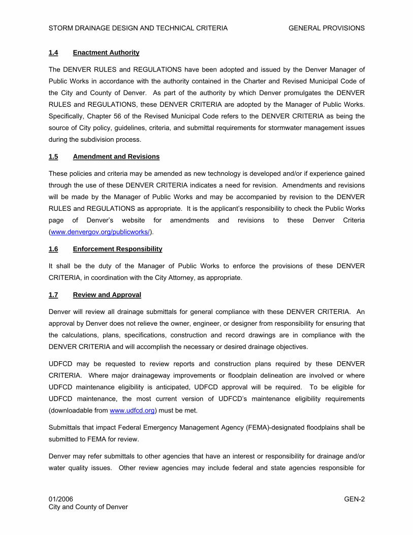
1.4 Enactment Authority
The DENVER RULES and REGULATIONS have been adopted and issued by the Denver Manager of
Public Works in accordance with the authority contained in the Charter and Revised Municipal Code of
the City and County of Denver. As part of the authority by which Denver promulgates the DENVER
RULES and REGULATIONS, these DENVER CRITERIA are adopted by the Manager of Public Works.
Specifically, Chapter 56 of the Revised Municipal Code refers to the DENVER CRITERIA as being the
source of City policy, guidelines, criteria, and submittal requirements for stormwater management issues
during the subdivision process.
1.5 Amendment and Revisions
These policies and criteria may be amended as new technology is developed and/or if experience gained
through the use of these DENVER CRITERIA indicates a need for revision. Amendments and revisions
will be made by the Manager of Public Works and may be accompanied by revision to the DENVER
RULES and REGULATIONS as appropriate. It is the applicant’s responsibility to check the Public Works
page of Denver’s website for amendments and revisions to these Denver Criteria
(www.denvergov.org/publicworks/).
1.6 Enforcement Responsibility
It shall be the duty of the Manager of Public Works to enforce the provisions of these DENVER
CRITERIA, in coordination with the City Attorney, as appropriate.
1.7 Review and Approval
Denver will review all drainage submittals for general compliance with these DENVER CRITERIA. An
approval by Denver does not relieve the owner, engineer, or designer from responsibility for ensuring that
the calculations, plans, specifications, construction and record drawings are in compliance with the
DENVER CRITERIA and will accomplish the necessary or desired drainage objectives.
UDFCD may be requested to review reports and construction plans required by these DENVER
CRITERIA. Where major drainageway improvements or floodplain delineation are involved or where
UDFCD maintenance eligibility is anticipated, UDFCD approval will be required. To be eligible for
UDFCD maintenance, the most current version of UDFCD’s maintenance eligibility requirements
(downloadable from www.udfcd.org) must be met.
Submittals that impact Federal Emergency Management Agency (FEMA)-designated floodplains shall be
submitted to FEMA for review.
Denver may refer submittals to other agencies that have an interest or responsibility for drainage and/or
water quality issues. Other review agencies may include federal and state agencies responsible for
01/2006 GEN-2 City and County of Denver
STORM DRAINAGE DESIGN AND TECHNICAL CRITERIA GENERAL PROVISIONS
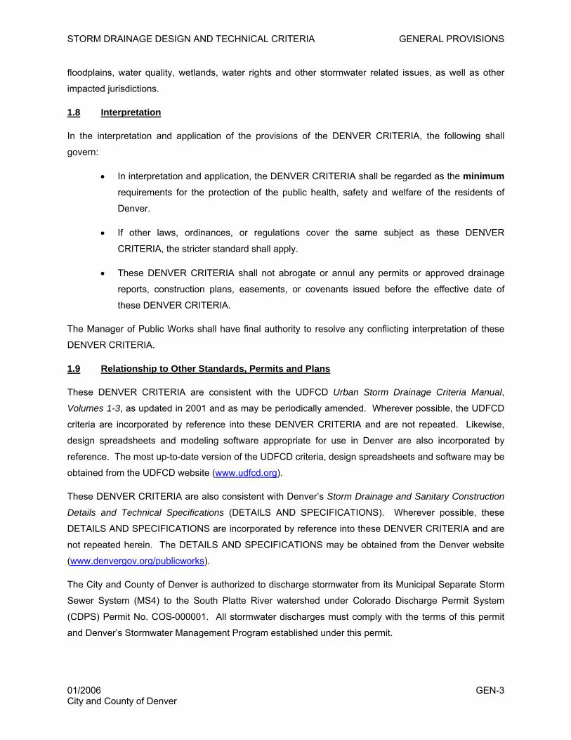
floodplains, water quality, wetlands, water rights and other stormwater related issues, as well as other
impacted jurisdictions.
1.8 Interpretation
In the interpretation and application of the provisions of the DENVER CRITERIA, the following shall
govern:
• In interpretation and application, the DENVER CRITERIA shall be regarded as the minimum
requirements for the protection of the public health, safety and welfare of the residents of
Denver.
• If other laws, ordinances, or regulations cover the same subject as these DENVER
CRITERIA, the stricter standard shall apply.
• These DENVER CRITERIA shall not abrogate or annul any permits or approved drainage
reports, construction plans, easements, or covenants issued before the effective date of
these DENVER CRITERIA.
The Manager of Public Works shall have final authority to resolve any conflicting interpretation of these
DENVER CRITERIA.
1.9 Relationship to Other Standards, Permits and Plans
These DENVER CRITERIA are consistent with the UDFCD Urban Storm Drainage Criteria Manual,
Volumes 1-3, as updated in 2001 and as may be periodically amended. Wherever possible, the UDFCD
criteria are incorporated by reference into these DENVER CRITERIA and are not repeated. Likewise,
design spreadsheets and modeling software appropriate for use in Denver are also incorporated by
reference. The most up-to-date version of the UDFCD criteria, design spreadsheets and software may be
obtained from the UDFCD website (www.udfcd.org).
These DENVER CRITERIA are also consistent with Denver’s Storm Drainage and Sanitary Construction
Details and Technical Specifications (DETAILS AND SPECIFICATIONS). Wherever possible, these
DETAILS AND SPECIFICATIONS are incorporated by reference into these DENVER CRITERIA and are
not repeated herein. The DETAILS AND SPECIFICATIONS may be obtained from the Denver website
(www.denvergov.org/publicworks).
The City and County of Denver is authorized to discharge stormwater from its Municipal Separate Storm
Sewer System (MS4) to the South Platte River watershed under Colorado Discharge Permit System
(CDPS) Permit No. COS-000001. All stormwater discharges must comply with the terms of this permit
and Denver’s Stormwater Management Program established under this permit.
01/2006 GEN-3 City and County of Denver
STORM DRAINAGE DESIGN AND TECHNICAL CRITERIA GENERAL PROVISIONS
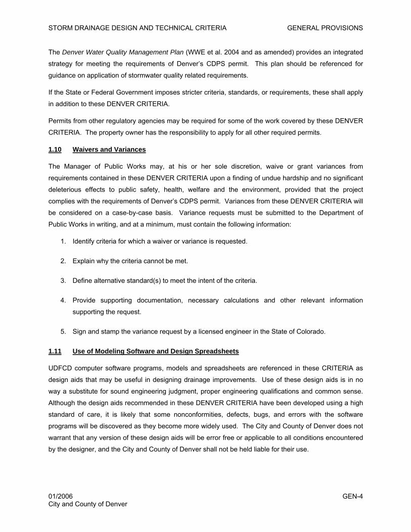
The Denver Water Quality Management Plan (WWE et al. 2004 and as amended) provides an integrated
strategy for meeting the requirements of Denver’s CDPS permit. This plan should be referenced for
guidance on application of stormwater quality related requirements.
If the State or Federal Government imposes stricter criteria, standards, or requirements, these shall apply
in addition to these DENVER CRITERIA.
Permits from other regulatory agencies may be required for some of the work covered by these DENVER
CRITERIA. The property owner has the responsibility to apply for all other required permits.
1.10 Waivers and Variances
The Manager of Public Works may, at his or her sole discretion, waive or grant variances from
requirements contained in these DENVER CRITERIA upon a finding of undue hardship and no significant
deleterious effects to public safety, health, welfare and the environment, provided that the project
complies with the requirements of Denver’s CDPS permit. Variances from these DENVER CRITERIA will
be considered on a case-by-case basis. Variance requests must be submitted to the Department of
Public Works in writing, and at a minimum, must contain the following information:
1. Identify criteria for which a waiver or variance is requested.
2. Explain why the criteria cannot be met.
3. Define alternative standard(s) to meet the intent of the criteria.
4. Provide supporting documentation, necessary calculations and other relevant information
supporting the request.
5. Sign and stamp the variance request by a licensed engineer in the State of Colorado.
1.11 Use of Modeling Software and Design Spreadsheets
UDFCD computer software programs, models and spreadsheets are referenced in these CRITERIA as
design aids that may be useful in designing drainage improvements. Use of these design aids is in no
way a substitute for sound engineering judgment, proper engineering qualifications and common sense.
Although the design aids recommended in these DENVER CRITERIA have been developed using a high
standard of care, it is likely that some nonconformities, defects, bugs, and errors with the software
programs will be discovered as they become more widely used. The City and County of Denver does not
warrant that any version of these design aids will be error free or applicable to all conditions encountered
by the designer, and the City and County of Denver shall not be held liable for their use.
01/2006 GEN-4 City and County of Denver
STORM DRAINAGE DESIGN AND TECHNICAL CRITERIA SUBMITTAL REQUIREMENTS
2.0 DRAINAGE REPORT AND CONSTRUCTION DRAWING SUBMITTAL REQUIREMENTS
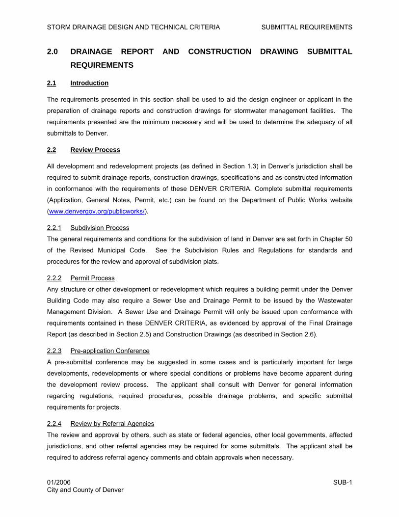
2.1 Introduction
The requirements presented in this section shall be used to aid the design engineer or applicant in the
preparation of drainage reports and construction drawings for stormwater management facilities. The
requirements presented are the minimum necessary and will be used to determine the adequacy of all
submittals to Denver.
2.2 Review Process
All development and redevelopment projects (as defined in Section 1.3) in Denver’s jurisdiction shall be
required to submit drainage reports, construction drawings, specifications and as-constructed information
in conformance with the requirements of these DENVER CRITERIA. Complete submittal requirements
(Application, General Notes, Permit, etc.) can be found on the Department of Public Works website
(www.denvergov.org/publicworks/).
2.2.1 Subdivision Process
The general requirements and conditions for the subdivision of land in Denver are set forth in Chapter 50
of the Revised Municipal Code. See the Subdivision Rules and Regulations for standards and
procedures for the review and approval of subdivision plats.
2.2.2 Permit Process
Any structure or other development or redevelopment which requires a building permit under the Denver
Building Code may also require a Sewer Use and Drainage Permit to be issued by the Wastewater
Management Division. A Sewer Use and Drainage Permit will only be issued upon conformance with
requirements contained in these DENVER CRITERIA, as evidenced by approval of the Final Drainage
Report (as described in Section 2.5) and Construction Drawings (as described in Section 2.6).
2.2.3 Pre-application Conference
A pre-submittal conference may be suggested in some cases and is particularly important for large
developments, redevelopments or where special conditions or problems have become apparent during
the development review process. The applicant shall consult with Denver for general information
regarding regulations, required procedures, possible drainage problems, and specific submittal
requirements for projects.
2.2.4 Review by Referral Agencies
The review and approval by others, such as state or federal agencies, other local governments, affected
jurisdictions, and other referral agencies may be required for some submittals. The applicant shall be
required to address referral agency comments and obtain approvals when necessary.
01/2006 SUB-1 City and County of Denver
STORM DRAINAGE DESIGN AND TECHNICAL CRITERIA SUBMITTAL REQUIREMENTS
2.2.5 Stand-alone Drainage Report
The drainage report shall be a stand-alone document. When references are made or assumptions are
based on previously approved submitted reports, the drainage report must include the appropriate
excerpts, pages, tables, and maps containing the referenced information. Assumptions made in previous
reports must be verified and substantiated. All submitted reports should be clearly and cleanly
reproduced. Photocopies of charts, tables, nomographs, calculations, or any other referenced material
must be legible.
2.2.6 Submittal Adequacy
The submittal checklist provided at the end of this chapter and the requirements specified in Sections 2.4
through 2.6 will be used by Denver to determine the adequacy of the submittal. Incomplete or absent
information may result in the report being returned to the author without review. Denver reserves the right
to require additional information with any submittal.
2.3 Acceptance
2.3.1 Final Drainage Report and Construction Drawings Approval Required for Construction
Acceptance of a final drainage report and construction drawings must be obtained prior to construction of
any drainage improvements within Denver. Preliminary drainage reports are conceptual and are
reviewed by Denver, but they do not receive a formal acceptance and cannot be used for construction.
The approval of a drainage report based on submitted documents and information shall not prevent the
Department of Public Works from requiring the correction of errors.
2.3.2 One-year Approval Period
Final drainage reports will be considered approved for a period of one (1) year. Construction based upon
any approved drainage report must commence within this one-year period.
2.3.3 Expired Acceptance
Approved drainage reports that have exceeded the one-year period may be re-approved on a case-by-
case basis. In order to be re-approved, it must be demonstrated that the report is consistent with the
current DENVER CRITERIA. If new drainage concepts and standards have been developed, or if any
drainage concept or pattern has changed, a new report will be required. Preliminary and Master
Drainage Reports conducted for a Master Development Plan are conceptual and are not affected by the
approval period.
2.4 Preliminary Drainage Report
If it is determined during the development review process that the project is of sufficient size or
complexity, a preliminary drainage report may be required in advance of the final drainage report. This
may also be done at the developer’s request. Two copies of the preliminary drainage report, prepared
01/2006 SUB-2 City and County of Denver

STORM DRAINAGE DESIGN AND TECHNICAL CRITERIA SUBMITTAL REQUIREMENTS
and signed by a professional engineer licensed in the State of Colorado, shall be submitted to the
Department of Public Works for review.
2.4.1 Preliminary Drainage Report Contents
The purpose of the Preliminary Drainage Report is to conceptually define the nature of the proposed
development or project, describe all existing conditions and propose facilities needed to conform to the
requirements of these DENVER CRITERIA. The following is an outline of the minimum Preliminary
Drainage Report requirements: (Note: Denver reserves the right to require additional information with any
submittal.)
1. General Location and Description
A. Location
i. City, county, state highway and local streets within and adjacent to the site or the
area to be served by the drainage improvements.
ii. Township, range, section, ¼ section, subdivision, lot and block.
iii. Names of surrounding developments.
B. Description of Property
i. General project description, including proposed land use.
ii. Area in acres.
iii. Ground cover (type of trees, shrubs, vegetation, hydrologic soil group, topography,
and slope).
iv. Major drainageways and drainage facilities.
v. Existing major irrigation facilities such as ditches and canals.
vi. History of flooding.
vii. Easements within and adjacent to the site.
2. Major Drainage Basins and Sub-basins
A. Major Basin Description
i. Reference to major drainageway planning studies such as flood hazard area
delineation (FHAD) reports, major drainageway master planning reports and flood
insurance rate maps (FIRMs); include a copy of current FIRM showing the location of
subject property.
01/2006 SUB-3 City and County of Denver
STORM DRAINAGE DESIGN AND TECHNICAL CRITERIA SUBMITTAL REQUIREMENTS
ii. Major basin drainage characteristics, existing and planned land uses within the basin,
as defined by the Planning Department.
iii. All nearby irrigation facilities within 100 feet of the property, which will influence or be
influenced by the local drainage.
B. Sub-basin Description
i. Historic drainage patterns of the property in question.
ii. Onsite and offsite sub-basin characteristics.
3. Drainage Facility Design
A. General Concept
i. Drainage concept and typical drainage patterns.
ii. Compliance with offsite runoff considerations.
iii. Anticipated and proposed drainage patterns.
iv. Content of tables, charts, figures, or drawings presented in the report.
B. Specific Details
i. Flows, volumes and water quality capture volumes (WQCV).
ii. Existing stormwater conveyance and storage facilities.
iii. Proposed stormwater conveyances, storage facilities and outlet structures.
iv. Relationship to both upstream and downstream properties and impact of the
development’s drainage on these properties; include discussion of offsite drainage
flow patterns and impact on development under existing and fully developed basin
conditions as defined by the Planning Department.
v. Drainage problems encountered and solutions at specific design points.
vi. Maintenance (whose responsibility and frequency), public safety and access aspects
of the drainage facilities.
vii. Compliance with other local, state and federal requirements.
viii. Structural and non-structural best management practices (BMPs) that will be part of
stormwater management design.
01/2006 SUB-4 City and County of Denver

STORM DRAINAGE DESIGN AND TECHNICAL CRITERIA SUBMITTAL REQUIREMENTS
ix. When deemed necessary by the Review Engineer, electronic update to the Denver
Drainage Master Plan in a format specified by the Review Engineer.
4. Conclusions
A. Compliance with Standards
i. DENVER CRITERIA.
ii. Major Drainageway Planning Studies.
iii. DISTRICT MANUAL.
iv. Denver’s Municipal Colorado Discharge Permit System (CDPS) Stormwater Permit.
v. Justification for any requested waiver.
B. Drainage Concept
i. Effectiveness of drainage design to control damage from storm runoff.
ii. Influence of proposed development on master drainage plan recommendation(s).
iii. Drainage impacts of proposed development on upstream and downstream
properties.
C. Water Quality
i. Measures implemented to treat the WQCV.
5. References
Reference all criteria, master plans, and technical information used in support of concept. The
Preliminary Design Report must be a stand-alone document including portions of relevant documents
referenced in the report. This supporting information may be included as an appendix.
6. Appendices
Appendices should be provided, as needed, to provide supporting information for the report.
2.4.2 Preliminary Drainage Plan Contents
1. Overall Drainage Plan
A. 24” X 36” in size.
B. Boundaries of entire development or project.
C. Limits of all major basins, including offsite basins.
01/2006 SUB-5 City and County of Denver
STORM DRAINAGE DESIGN AND TECHNICAL CRITERIA SUBMITTAL REQUIREMENTS
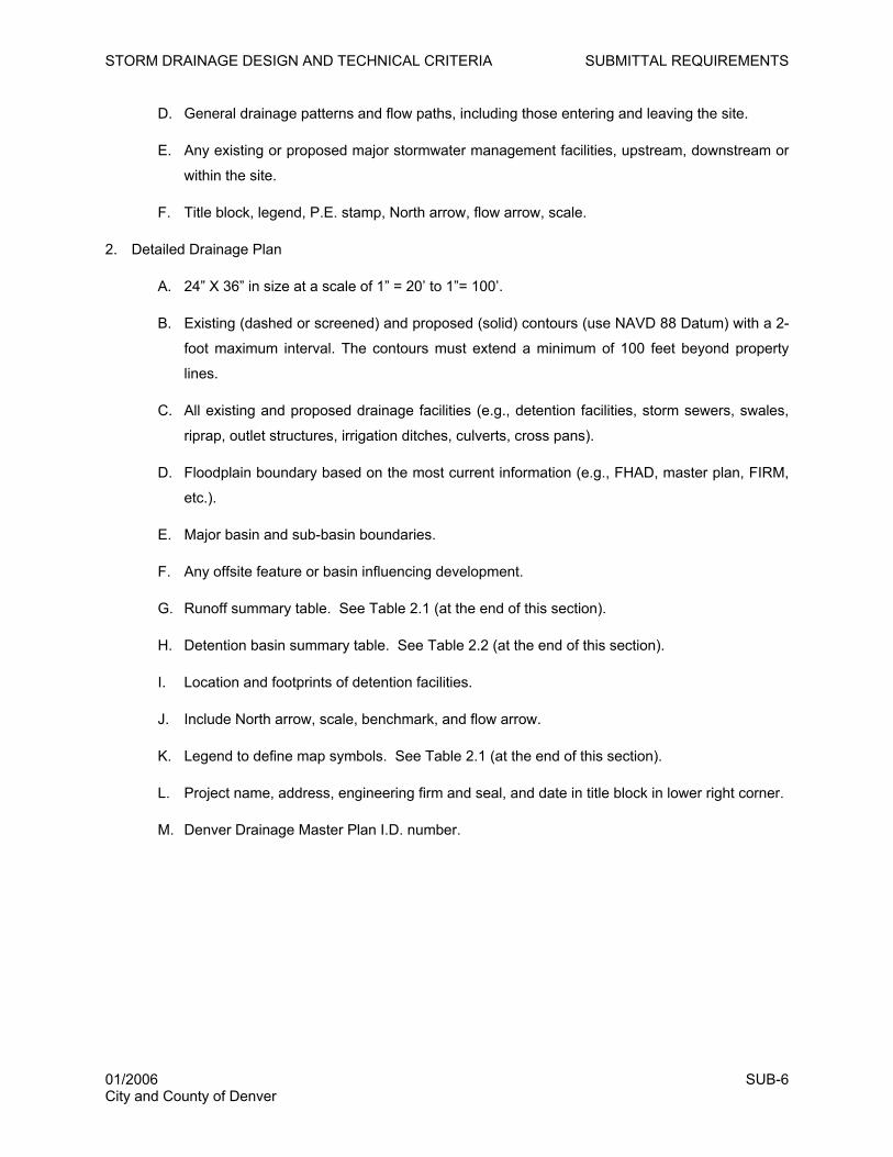
D. General drainage patterns and flow paths, including those entering and leaving the site.
E. Any existing or proposed major stormwater management facilities, upstream, downstream or
within the site.
F. Title block, legend, P.E. stamp, North arrow, flow arrow, scale.
2. Detailed Drainage Plan
A. 24” X 36” in size at a scale of 1” = 20’ to 1”= 100’.
B. Existing (dashed or screened) and proposed (solid) contours (use NAVD 88 Datum) with a 2-
foot maximum interval. The contours must extend a minimum of 100 feet beyond property
lines.
C. All existing and proposed drainage facilities (e.g., detention facilities, storm sewers, swales,
riprap, outlet structures, irrigation ditches, culverts, cross pans).
D. Floodplain boundary based on the most current information (e.g., FHAD, master plan, FIRM,
etc.).
E. Major basin and sub-basin boundaries.
F. Any offsite feature or basin influencing development.
G. Runoff summary table. See Table 2.1 (at the end of this section).
H. Detention basin summary table. See Table 2.2 (at the end of this section).
I. Location and footprints of detention facilities.
J. Include North arrow, scale, benchmark, and flow arrow.
K. Legend to define map symbols. See Table 2.1 (at the end of this section).
L. Project name, address, engineering firm and seal, and date in title block in lower right corner.
M. Denver Drainage Master Plan I.D. number.
01/2006 SUB-6 City and County of Denver
STORM DRAINAGE DESIGN AND TECHNICAL CRITERIA SUBMITTAL REQUIREMENTS
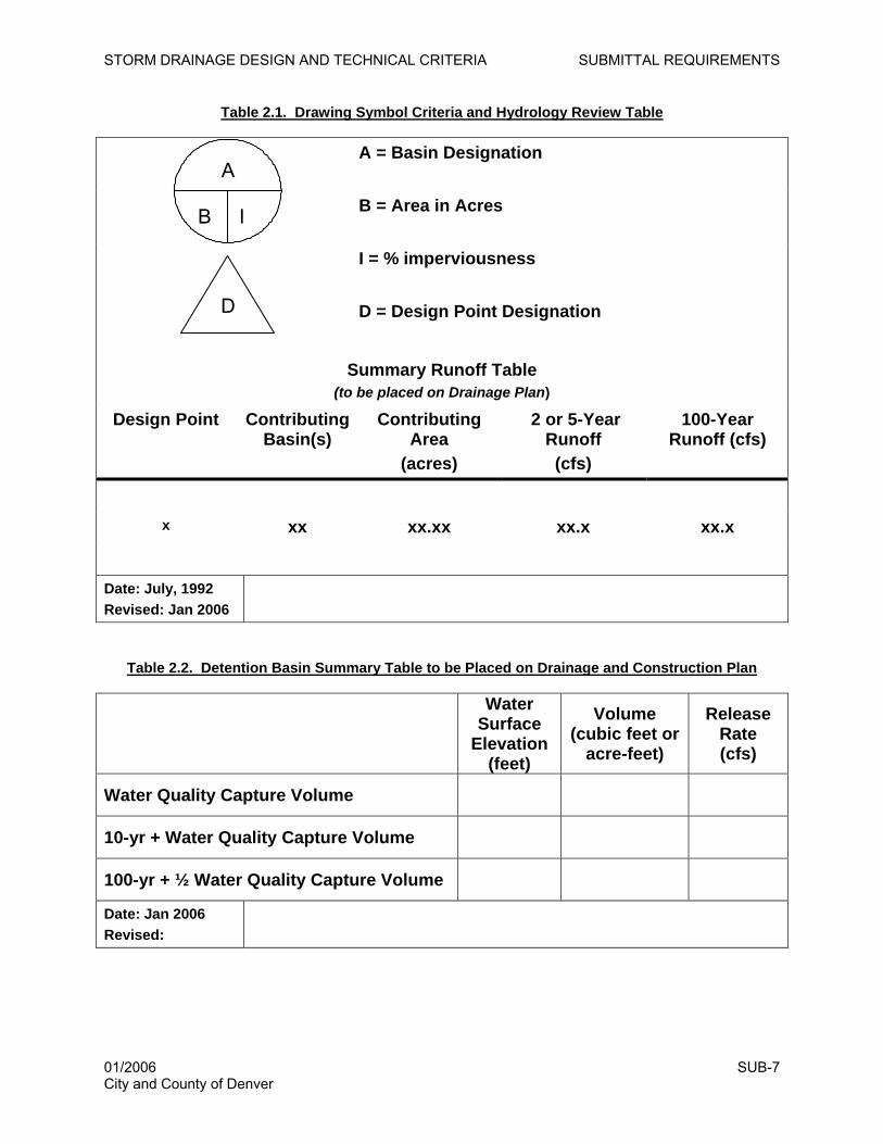
Table 2.1. Drawing Symbol Criteria and Hydrology Review Table
A = Basin Designation B = Area in Acres I = % imperviousness
D = Design Point Designation
Summary Runoff Table (to be placed on Drainage Plan)
Design Point Contributing Basin(s)
Contributing Area
(acres)
2 or 5-Year Runoff (cfs)
100-Year Runoff (cfs)
x xx xx.xx xx.x xx.x
Date: July, 1992 Revised: Jan 2006
D
A
B I
Table 2.2. Detention Basin Summary Table to be Placed on Drainage and Construction Plan
Water
Surface Elevation
(feet)
Volume (cubic feet or
acre-feet)
Release Rate (cfs)
Water Quality Capture Volume
10-yr + Water Quality Capture Volume
100-yr + ½ Water Quality Capture Volume
Date: Jan 2006 Revised:
01/2006 SUB-7 City and County of Denver
STORM DRAINAGE DESIGN AND TECHNICAL CRITERIA SUBMITTAL REQUIREMENTS
2.5 Final Drainage Report
The Final Drainage Report serves to define and expand the concepts shown in the Preliminary Drainage
Report and to assure conformance to these DENVER CRITERIA. The final report may be submitted at
any point during the permitting and platting process, but must be reviewed and approved prior to approval
of the subdivision plat or issuance of the Sewer Use and Drainage Permit. Two copies of the report shall
be submitted to the Public Works Department. Reports shall be typed and bound on 8½” X 11” paper
with all pages numbered. The report shall include a cover letter presenting the design review.
2.5.1 Certification Statement
The report shall contain a certification page with the following statement:
This report for the drainage design of (Name of Development) was prepared by me (or under my supervision) in accordance with the provisions of City and County of Denver Storm Drainage Design and Technical Criteria, and was designed to comply with the provisions thereof. I understand that the City and County of Denver does not, and will not, assume liability for drainage facilities designed by others.
By: ___________________________ Licensed Professional Engineer State of Colorado No. ___________ Affix Seal
2.5.2 Final Drainage Report Contents
The report shall be in accordance with, but not limited to, the following outline and contain the applicable
information listed below. Denver reserves the right to require additional information with any submittal.
1. General Location and Description. See Section 2.4.1, #1
2. Major Drainage Basins and Sub-basins. See Section 2.4.1, #2
3. Drainage Design Criteria
A. Regulations: Discuss optional provisions selected or deviation from the DENVER CRITERIA,
if any, and their justification.
B. Development Criteria References and Constraints.
i. Previous drainage studies (e.g., project master plans, Urban Drainage and Flood
Control District [UDFCD] outfall system plans, Denver Drainage Master Plan) for the
site that influence, or are influenced by, the proposed drainage design and how the
studies will affect drainage design for the site.
ii. Relationship to and implications of adjacent drainage studies.
01/2006 SUB-8 City and County of Denver
STORM DRAINAGE DESIGN AND TECHNICAL CRITERIA SUBMITTAL REQUIREMENTS
iii. Drainage impact of site constraints such as streets, utilities, transit ways, existing
structures, and development or site plans.
C. Hydrologic Criteria
i. Design rainfall.
ii. Hydrologic soil group.
iii. Runoff calculation method(s).
iv. Detention discharge and storage calculation method.
v. Design storm recurrence intervals.
vi. Justification for other criteria or calculation methods used that are not presented in or
referenced by the DENVER CRITERIA.
D. Hydraulic Criteria
i. Various capacity methods.
ii. Hydraulic grade line (HGL) calculation method and head loss coefficients.
iii. Routing method used.
iv. Other drainage facility design criteria used that are not presented in the DENVER
CRITERIA.
E. Water Quality Requirements Under Denver’s Municipal CDPS Stormwater Permit
i. Design procedures and WQCV for the site.
ii. Permanent, post-construction best management practices (BMPs) for treatment of
the WQCV.
iii. Landscaping requirements.
iv. Maintenance requirements for BMPs.
F. Waivers from Criteria
i. Provisions by section number for which a waiver is requested.
ii. Justification for each waiver requested.
4. Drainage Facility Design
A. General Concept. See Section 2.4.1, #3 (A).
01/2006 SUB-9 City and County of Denver
STORM DRAINAGE DESIGN AND TECHNICAL CRITERIA SUBMITTAL REQUIREMENTS
B. Specific Details. See Section 2.4.1, #3 (B) and in addition include:
i. Easements and tracts for drainage purposes, including the conditions and limitations
for use.
ii. All structural and non-structural BMPs, including tributary areas, sizing, treatment
volumes, design features, etc.
5. Conclusions. See Section 2.4.1, #4.
6. References
Reference all criteria and technical information used. The final report must be a stand-alone
document including portions of relevant documents referenced in the report. This supporting
information may be included as an appendix.
7. Appendices
A. Hydrologic Computations
i. Land use assumptions regarding adjacent properties.
ii. Time of concentration and runoff coefficients for each basin.
iii. Minor and major storm runoff at specific design points.
iv. Connectivity diagram showing relationship/connectivity of basins, conveyance
facilities, detention basins and design points.
v. Electronic copy and hard copy of input/output listings for computer models used.
B. Hydraulic Computations
i. Street capacity as compared to allowable capacity using Figure 7.1.
ii. Inlet capacity as compared to allowable capacity using Figures 8.1 and 8.2.
iii. Storm sewer capacity, including HGL elevations and head loss coefficients.
iv. Energy grade line (EGL) when the storm sewer is designed for events higher than the
minor event or is requested by the Public Works Review Engineer.
v. Open channel design, low flow and trickle channel design, stabilization and grade
control improvements.
vi. Energy dissipation at pipe outlets.
vii. Water surface profiles.
01/2006 SUB-10 City and County of Denver
STORM DRAINAGE DESIGN AND TECHNICAL CRITERIA SUBMITTAL REQUIREMENTS
viii. Culvert capacities.
ix. Stage-Storage-Discharge determination for detention basins.
x. Downstream/outfall system capacity of the major drainageway.
xi. Charts, figures and tables related to hydraulic computations.
xii. Electronic and hard copy of input/output listings for computer models used.
C. Water Quality Enhancement BMPs
i. Completed DISTRICT MANUAL Volume 3 design procedure form.
ii. Design and sizing.
iii. Charts, figures, tables, and details related to design.
D. Excerpts from supporting documents, if referenced in report.
2.5.3 Final Drainage Plan Contents
1. Overall Drainage Plan. See Section 2.4.2, #1
2. Detailed Drainage Plan. See Section 2.4.2, #2 and in addition include:
A. Property lines and easements with purposes noted.
B. Adjacent developments or property ownerships.
C. Street cross-section indicating ROW width, flow-line width, cross slope, sidewalk, and curb
type.
D. Street slope and flow direction and cross-pan.
E. Proposed storm sewers and open drainageways, including inlets, manholes, culverts, and
other appurtenances, including riprap protection.
F. Proposed outfalls or exit points for runoff from the developed area and facilities to convey
flows to the final outfall point without damage to downstream properties.
G. Finished floor elevation of proposed and existing structures.
H. Proposed detention basin grading and detention basin outlet schematic, include overflow
directions and amounts and emergency spillway.
I. Water quality enhancement BMPs schematic.
01/2006 SUB-11 City and County of Denver
STORM DRAINAGE DESIGN AND TECHNICAL CRITERIA SUBMITTAL REQUIREMENTS
2.6 Construction Drawings
2.6.1 Improvement Requirements
Drainage improvements within Denver are required to be designed, constructed and accepted in
accordance with Denver standards and criteria. Construction plans are required to be approved by the
Department of Public Works for all facilities within Denver.
The information required for the plans shall be in accordance with sound engineering principles, these
DENVER CRITERIA, Denver’s Municipal CDPS Stormwater Permit, and other applicable Denver
ordinances, regulations, criteria or design guidelines. The plans may also be subject to review by outside
agencies such as UDFCD, Federal Emergency Management Agency (FEMA), U.S. Army Corps of
Engineers, U.S. Environmental Protection Agency or others as required. All plans must comply with the
requirements of the current International Building Code, as may be amended. The approval of
construction plans based on submitted documents and information shall not prevent Public Works from
requiring correction of errors.
2.6.2 Certification
Construction drawings submitted for review and acceptance shall be prepared by a professional engineer
licensed in the State of Colorado. The construction drawings must include the following statement on the
cover sheet:
“These construction drawings for (name of subdivision, development, or project) were prepared by me (or under my direct supervision) in accordance with the requirements of the Storm Drainage and Sanitary Construction Details and Technical Specifications and the Storm Drainage Design and Technical Criteria of the City and County of Denver.
By: ___________________________ Licensed Professional Engineer State of Colorado No. ___________ Affix Seal
Name of Firm__________________
2.6.3 Construction Plan Requirements
The construction plans (24” X 36”) for drainage improvements shall include both general drainage
improvement and specific design feature information, as described below. Denver reserves the right to
require additional information with any submittal.
1. General Information Required for All Drainage Improvement Projects
A. Cover sheet
i. Vicinity map.
ii. Professional engineer certification.
01/2006 SUB-12 City and County of Denver
STORM DRAINAGE DESIGN AND TECHNICAL CRITERIA SUBMITTAL REQUIREMENTS
iii. Title block, sheet index.
iv. Denver standard notes (see www.denvergov.org/publicworks/) for the most current
version).
B. Overall utility plan showing water, sanitary and storm sewer facilities.
C. Grading plan (Use NAVD 88 Datum).
D. Drainage plan.
E. Erosion and sedimentation control plan (refer to Chapter 15).
F. Basic information.
i. Property and right-of-way lines, existing and proposed easements, tracts, structures,
fences, and other land features.
ii. Relation of site to current floodplain boundaries.
iii. Maintenance access.
iv. Utilities adjacent to or crossing stormwater management facilities.
v. Additional design details as required.
vi. Any non-Denver standard details.
2. Specific Design Feature Information
A. Storm Sewers and Culverts
i. Plan and profile of proposed pipe installations, inlets, manholes, junction boxes and
outlet structures with pertinent elevations, dimensions, types, designs and pipe full
flow rates and horizontal controls shown. Plan and profile shall be included on same
sheet.
ii. Minor storm HGLs.
iii. Major storm HGLs if the facility is designed for events greater than the minor storm.
iv. Pipe outlet protection on plan and profile views.
v. Utilities adjacent to or crossing storm sewer or culvert alignment in plan and profile.
vi. 1” = 20’ scale, minimum, grading details for all pipe and culvert inlets and outlets.
01/2006 SUB-13 City and County of Denver
STORM DRAINAGE DESIGN AND TECHNICAL CRITERIA SUBMITTAL REQUIREMENTS
B. Detention/Storage Facilities
i. Detention basin grading, trickle channel, inlet, outlet, and emergency overflow
spillway locations.
ii. Detention facility summary, Table 2.2 (at the end of Section 2.4.2).
iii. Forebay, micropool, trickle channel and outlet construction details, including safety
features, such as racks at openings.
iv. Finished floor of structures adjacent to detention basins.
C. Open Channels, Swales, Channel Stabilization
i. Plan view showing horizontal locations of existing and proposed channels and
swales, including locations of grade control structures and stabilization measures,
such as check structures, drop structures, toe protection, bank stabilization, low-flow
or trickle channels, with appropriate horizontal controls, safety features, etc.
ii. Profile along channel alignment with all invert elevations and top-of-channel bank
elevations and design flow rates.
iii. Water surface limits in plan view.
iv. Water surface profiles for the minor and major storms.
v. Side tributary channels and pipe outlets.
D. Water Quality Enhancement BMPs
i. Plan and profile of improvements as required.
ii. Design details as required.
2.7 As-built Drawings and Certifications
Upon completion of construction, as-built drawings shall be submitted in hard copy (paper set and Mylar
set) and electronic copy. Certifications of the as-built drawings are required as follows:
• Licensed Land Surveyor: A licensed land surveyor in the State of Colorado shall certify the as-built
detention basin volumes and outlet structure sizes and elevations, storm sewer sizes and invert
elevations at inlets, manholes and discharge locations, longitudinal slopes and representative cross
sections of open channels and dimensions of drainage structures.
01/2006 SUB-14 City and County of Denver
STORM DRAINAGE DESIGN AND TECHNICAL CRITERIA SUBMITTAL REQUIREMENTS
• Licensed Professional Engineer: The responsible design engineer shall submit a completed
“Certificate of Inspection.” See the Department of Public Works website
(www.denvergov.org/publicworks/) for requirements.
Certificate of Inspection and as-built drawings and all necessary approvals from all the entities (e.g.,
UDFCD approval for master drainageway improvements, FEMA approval for floodplain, etc.) will be
required prior to the issuance of a sanitary sewer connection permit or the signing of a Certificate of
Occupancy.
01/2006 SUB-15 City and County of Denver
STORM DRAINAGE DESIGN AND TECHNICAL CRITERIA SUBMITTAL REQUIREMENTS
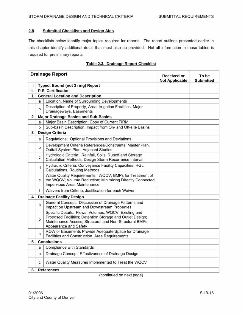
2.8 Submittal Checklists and Design Aids
The checklists below identify major topics required for reports. The report outlines presented earlier in
this chapter identify additional detail that must also be provided. Not all information in these tables is
required for preliminary reports.
Table 2.3. Drainage Report Checklist
Drainage Report
Received or Not Applicable
To be Submitted
i Typed, Bound (not 3 ring) Report ii. P.E. Certification 1 General Location and Description a Location, Name of Surrounding Developments
b Description of Property, Area, Irrigation Facilities, Major Drainageways, Easements
2 Major Drainage Basins and Sub-Basins a Major Basin Description, Copy of Current FIRM b Sub-basin Description, Impact from On- and Off-site Basins 3 Design Criteria a Regulations: Optional Provisions and Deviations
b Development Criteria References/Constraints: Master Plan, Outfall System Plan, Adjacent Studies
c Hydrologic Criteria: Rainfall, Soils, Runoff and Storage Calculation Methods, Design Storm Recurrence Interval
d Hydraulic Criteria: Conveyance Facility Capacities, HGL Calculations, Routing Methods
e Water Quality Requirements: WQCV, BMPs for Treatment of the WQCV; Volume Reduction; Minimizing Directly Connected Impervious Area; Maintenance
f Waivers from Criteria, Justification for each Waiver 4 Drainage Facility Design
a General Concept: Discussion of Drainage Patterns and Impact on Upstream and Downstream Properties
b
Specific Details: Flows, Volumes, WQCV; Existing and Proposed Facilities; Detention Storage and Outlet Design; Maintenance Access; Structural and Non-Structural BMPs; Appearance and Safety
c ROW or Easements Provide Adequate Space for Drainage Facilities and Construction Area Requirements
5 Conclusions a Compliance with Standards b Drainage Concept, Effectiveness of Drainage Design
c Water Quality Measures Implemented to Treat the WQCV 6 References
(continued on next page)
01/2006 SUB-16 City and County of Denver
STORM DRAINAGE DESIGN AND TECHNICAL CRITERIA SUBMITTAL REQUIREMENTS
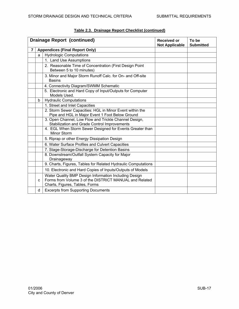
Table 2.3. Drainage Report Checklist (continued)
Drainage Report (continued)
Received or Not Applicable
To be Submitted
7 Appendices (Final Report Only) a Hydrologic Computations 1. Land Use Assumptions
2. Reasonable Time of Concentration (First Design Point Between 5 to 10 minutes)
3. Minor and Major Storm Runoff Calc. for On- and Off-site Basins
4. Connectivity Diagram/SWMM Schematic
5. Electronic and Hard Copy of Input/Outputs for Computer Models Used.
b Hydraulic Computations 1. Street and Inlet Capacities
2. Storm Sewer Capacities: HGL in Minor Event within the Pipe and HGL in Major Event 1 Foot Below Ground
3. Open Channel, Low Flow and Trickle Channel Design, Stabilization and Grade Control Improvements
4. EGL When Storm Sewer Designed for Events Greater than Minor Storm
5. Riprap or other Energy Dissipation Design 6. Water Surface Profiles and Culvert Capacities 7. Stage-Storage-Discharge for Detention Basins
8. Downstream/Outfall System Capacity for Major Drainageway
9. Charts, Figures, Tables for Related Hydraulic Computations 10. Electronic and Hard Copies of Inputs/Outputs of Models
c Water Quality BMP Design Information Including Design Forms from Volume 3 of the DISTRICT MANUAL and Related Charts, Figures, Tables, Forms
d Excerpts from Supporting Documents
01/2006 SUB-17 City and County of Denver
STORM DRAINAGE DESIGN AND TECHNICAL CRITERIA SUBMITTAL REQUIREMENTS
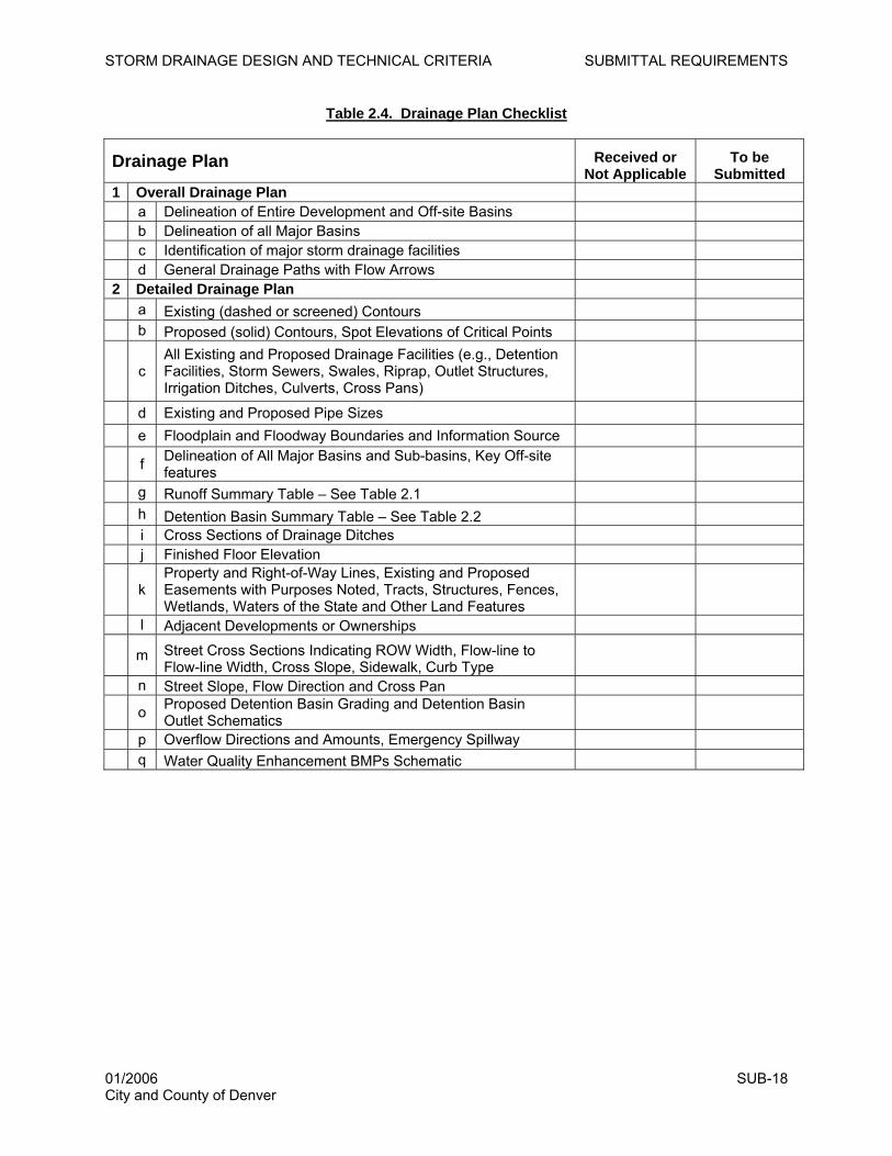
Table 2.4. Drainage Plan Checklist
Drainage Plan Received or Not Applicable
To be Submitted
1 Overall Drainage Plan a Delineation of Entire Development and Off-site Basins b Delineation of all Major Basins c Identification of major storm drainage facilities d General Drainage Paths with Flow Arrows 2 Detailed Drainage Plan a Existing (dashed or screened) Contours b Proposed (solid) Contours, Spot Elevations of Critical Points
c All Existing and Proposed Drainage Facilities (e.g., Detention Facilities, Storm Sewers, Swales, Riprap, Outlet Structures, Irrigation Ditches, Culverts, Cross Pans)
d Existing and Proposed Pipe Sizes e Floodplain and Floodway Boundaries and Information Source
f Delineation of All Major Basins and Sub-basins, Key Off-site features
g Runoff Summary Table – See Table 2.1 h Detention Basin Summary Table – See Table 2.2 i Cross Sections of Drainage Ditches j Finished Floor Elevation
k Property and Right-of-Way Lines, Existing and Proposed Easements with Purposes Noted, Tracts, Structures, Fences, Wetlands, Waters of the State and Other Land Features
l Adjacent Developments or Ownerships
m Street Cross Sections Indicating ROW Width, Flow-line to Flow-line Width, Cross Slope, Sidewalk, Curb Type
n Street Slope, Flow Direction and Cross Pan
o Proposed Detention Basin Grading and Detention Basin Outlet Schematics
p Overflow Directions and Amounts, Emergency Spillway q Water Quality Enhancement BMPs Schematic
01/2006 SUB-18 City and County of Denver
STORM DRAINAGE DESIGN AND TECHNICAL CRITERIA SUBMITTAL REQUIREMENTS
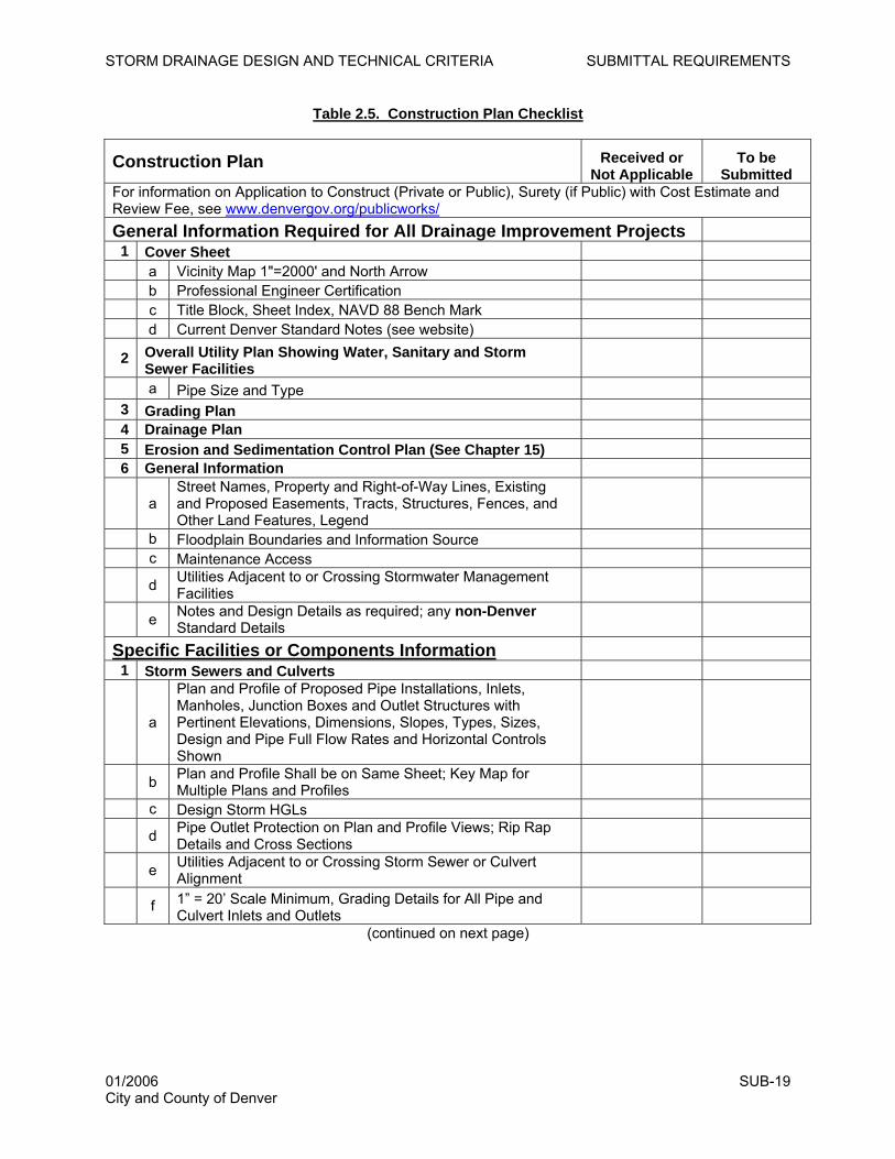
Table 2.5. Construction Plan Checklist
Construction Plan Received or Not Applicable
To be Submitted
For information on Application to Construct (Private or Public), Surety (if Public) with Cost Estimate and Review Fee, see www.denvergov.org/publicworks/General Information Required for All Drainage Improvement Projects
1 Cover Sheet a Vicinity Map 1"=2000' and North Arrow b Professional Engineer Certification c Title Block, Sheet Index, NAVD 88 Bench Mark d Current Denver Standard Notes (see website)
2 Overall Utility Plan Showing Water, Sanitary and Storm Sewer Facilities
a Pipe Size and Type 3 Grading Plan 4 Drainage Plan 5 Erosion and Sedimentation Control Plan (See Chapter 15) 6 General Information
a Street Names, Property and Right-of-Way Lines, Existing and Proposed Easements, Tracts, Structures, Fences, and Other Land Features, Legend
b Floodplain Boundaries and Information Source c Maintenance Access
d Utilities Adjacent to or Crossing Stormwater Management Facilities
e Notes and Design Details as required; any non-Denver Standard Details
Specific Facilities or Components Information 1 Storm Sewers and Culverts
a
Plan and Profile of Proposed Pipe Installations, Inlets, Manholes, Junction Boxes and Outlet Structures with Pertinent Elevations, Dimensions, Slopes, Types, Sizes, Design and Pipe Full Flow Rates and Horizontal Controls Shown
b Plan and Profile Shall be on Same Sheet; Key Map for Multiple Plans and Profiles
c Design Storm HGLs
d Pipe Outlet Protection on Plan and Profile Views; Rip Rap Details and Cross Sections
e Utilities Adjacent to or Crossing Storm Sewer or Culvert Alignment
f 1” = 20’ Scale Minimum, Grading Details for All Pipe and Culvert Inlets and Outlets
(continued on next page)
01/2006 SUB-19 City and County of Denver
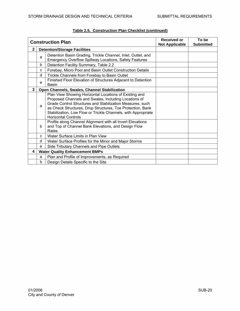
STORM DRAINAGE DESIGN AND TECHNICAL CRITERIA SUBMITTAL REQUIREMENTS
Table 2.5. Construction Plan Checklist (continued)
Construction Plan Received or Not Applicable
To be Submitted
2 Detention/Storage Facilities
a Detention Basin Grading, Trickle Channel, Inlet, Outlet, and Emergency Overflow Spillway Locations, Safety Features
b Detention Facility Summary, Table 2.2 c Forebay, Micro Pool and Basin Outlet Construction Details d Trickle Channels from Forebay to Basin Outlet
e Finished Floor Elevation of Structures Adjacent to Detention Basin
3 Open Channels, Swales, Channel Stabilization
a
Plan View Showing Horizontal Locations of Existing and Proposed Channels and Swales, Including Locations of Grade Control Structures and Stabilization Measures, such as Check Structures, Drop Structures, Toe Protection, Bank Stabilization, Low Flow or Trickle Channels, with Appropriate Horizontal Controls
b Profile along Channel Alignment with all Invert Elevations and Top of Channel Bank Elevations, and Design Flow Rates
c Water Surface Limits in Plan View d Water Surface Profiles for the Minor and Major Storms e Side Tributary Channels and Pipe Outlets
4 Water Quality Enhancement BMPs a Plan and Profile of Improvements, as Required b Design Details Specific to the Site
01/2006 SUB-20 City and County of Denver
STORM DRAINAGE DESIGN AND TECHNICAL CRITERIA DRAINAGE POLICY
3.0 DRAINAGE POLICY
3.1 Introduction
Providing adequate drainage in urban areas is necessary to preserve and promote the general health,
safety, welfare, and economic well being of the urban community. When planning for drainage, certain
underlying principles provide direction. These principles are made operational through policy statements.
The implementation of the policy is, in turn, facilitated by technical criteria and data. Over the past 35
years, the Urban Drainage and Flood Control District (UDFCD) has established strong policies that guide
drainage planning in the metro area, as specified in the DRAINAGE POLICY chapter of the DISTRICT
MANUAL. Denver hereby incorporates by reference all principles and policies contained therein. A brief discussion of the twelve key drainage principles contained in the DISTRICT MANUAL is provided,
followed by Denver’s policies based on these principles. Background information supporting
development of these policies can be obtained from the DRAINAGE POLICY and PLANNING chapters of
the DISTRICT MANUAL and is not repeated herein. Additionally, the DRAINAGE LAW chapter of the
DISTRICT MANUAL provides information on the legal responsibilities for those involved in design,
construction and maintenance of storm drainage facilities.
3.2 Principles
Twelve principles of urban stormwater management identified in the DISTRICT MANUAL are foundational
to these DENVER CRITERIA and are repeated herein due to their importance.
1. Drainage is a regional phenomenon that does not respect the boundaries between government jurisdictions or between properties. This makes it necessary to formulate programs
that include both public and private involvement. Overall, the governmental agencies most directly
involved must provide coordination and master planning, but drainage planning must be integrated on
a regional level if optimum results are to be achieved.
2. A stormwater management system is a subsystem of the total urban water resource system. Stormwater management system planning and design for any site must be compatible with regional
comprehensive plans and should be coordinated with planning for land use, open space, and
transportation corridors. Urban stormwater management must consider and address the interrelated
issues of erosion and sedimentation control, flood control, site grading criteria, and regional water
quality.
3. Every urban area has a minor and major drainage system that must be properly planned and designed. The minor system is designed to provide public convenience and to accommodate
moderate, frequently occurring flows. The major system, which exists regardless of whether it is
planned, carries more water and operates when the rate or volume of runoff exceeds the capacity of
01/2006 POL-1 City and County of Denver
STORM DRAINAGE DESIGN AND TECHNICAL CRITERIA DRAINAGE POLICY
the minor system. To provide for orderly urban growth, reduce costs to future generations, and avoid
loss of life and major property damage, both systems must be planned and properly engineered.
4. Runoff routing is primarily a space allocation problem. The volume of water present at a given
time in an urban region cannot be compressed or diminished. Adequate space must be provided
during initial planning stages for storm drainage runoff conveyance, quality enhancement, and
storage. Otherwise, stormwater runoff will conflict with other land uses, resulting in damages and the
disruption of other urban systems.
5. Planning and design of stormwater drainage systems generally shall not be based on the premise that problems can be transferred from one location to another. Urbanization tends to
increase downstream peak flows by increasing runoff volumes and the speed of runoff conveyance.
Stormwater management systems shall be designed and detention storage shall be provided so that
downstream properties are not adversely impacted.
6. An urban storm drainage strategy should be a multi-objective and multi-means effort. The
many competing demands placed upon space and resources require a stormwater management
strategy that meets a variety of objectives, including water quality enhancement, groundwater
recharge, recreation, wildlife, wetland creation, protection of landmarks/amenities, control of erosion
and sediment deposition, and creation of open spaces. The paramount objective must be protection
of public, health, safety and welfare.
7. Design of the stormwater drainage system shall consider the features, capacity, and function of the existing drainage system. Good designs incorporate the effectiveness of the natural
systems rather than negate, replace or ignore them. Existing features such as natural drainageways,
depressions, wetlands, floodplains, permeable soils, and vegetation provide for infiltration, help
control the velocity of runoff, extend the time of concentration, filter sediment and other pollutants,
and recycle nutrients.
8. In new developments, attempts should be made to reduce stormwater runoff rates and pollutant load increases after development to the maximum extent practicable. To the extent
feasible, the rate of runoff should be slowed by maximizing use of vegetative and porous land cover,
infiltration should be encouraged to reduce runoff volumes, and a series of best management
practices (BMPs) must be provided for water quality enhancement and protection.
9. The stormwater management system shall be designed beginning with the outlet or point of outflow from the project, giving full consideration to downstream effects and the effects of off-site flows entering the system. The design of the stormwater management system shall take into
account runoff from upstream sites, assuming fully developed conditions, and shall evaluate the
downstream conveyance system to ensure that it has sufficient capacity to accept design discharges
01/2006 POL-2 City and County of Denver
STORM DRAINAGE DESIGN AND TECHNICAL CRITERIA DRAINAGE POLICY
without adverse backwater or downstream impacts such as flooding, stream bank erosion, channel
degradation, and sediment deposition.
10. The stormwater management system must receive regular maintenance to ensure long-term function and effectiveness. Stormwater management facilities shall be designed with ease of maintenance, long-term function, protection of public safety and accessibility as primary considerations. Operation and maintenance procedures and activities must be developed and
documented with the facility design. Clear assignment of maintenance responsibilities must be
identified and assigned to an established agency with the resources and understanding that are
required to ensure proper maintenance.
11. Floodplains need to be preserved where feasible and practicable. Preservation of floodplains
serves to minimize hazards, preserve habitat and open space, creates a more livable urban
environment, and protects public health, safety, and welfare.
12. Sufficient right-of-way for lateral channel movement of incised floodplains must be reserved. Whenever a floodplain is contained within a narrow (i.e., degraded) channel, the channel should be
provided with grade control structures and a right-of-way corridor to account for lateral movement.
Lateral movement over time can cause extensive damages to public and private structures and
facilities.
3.3 Policies
In keeping with the 12 principles of storm drainage planning, Denver has developed specific policies that
must be followed. These policies are discussed in the following categories: planning, design, operation
and maintenance, irrigation and storage facilities, and water quality.
3.3.1 Planning
3.3.1.1 Storm drainage planning is required for all development and redevelopment projects
(as defined in Section 1.3) in accordance with these DENVER CRITERIA and the DISTRICT
MANUAL. Requirements for drainage plan submittals must comply with Chapter 2 of these
DENVER CRITERIA.
3.3.1.2 Stormwater management planning shall be required in the initial planning stages for
all developments and redevelopments (as defined in Section 1.3) to ensure that adequate space
is allocated for the drainage facilities.
3.3.1.3 Denver encourages multi-purpose uses of storm drainage facilities that are
compatible with adjacent land uses, Colorado Water Law and water quality enhancement
objectives. Special care shall be taken when storm drainage facilities are contained within
recreational, park and open space areas to ensure that uses are compatible.
01/2006 POL-3 City and County of Denver
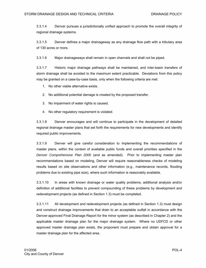
STORM DRAINAGE DESIGN AND TECHNICAL CRITERIA DRAINAGE POLICY
3.3.1.4 Denver pursues a jurisdictionally unified approach to promote the overall integrity of
regional drainage systems.
3.3.1.5 Denver defines a major drainageway as any drainage flow path with a tributary area
of 130 acres or more.
3.3.1.6 Major drainageways shall remain in open channels and shall not be piped.
3.3.1.7 Historic major drainage pathways shall be maintained, and inter-basin transfers of
storm drainage shall be avoided to the maximum extent practicable. Deviations from this policy
may be granted on a case-by-case basis, only when the following criteria are met:
1. No other viable alternative exists.
2. No additional potential damage is created by the proposed transfer.
3. No impairment of water rights is caused.
4. No other regulatory requirement is violated.
3.3.1.8 Denver encourages and will continue to participate in the development of detailed
regional drainage master plans that set forth the requirements for new developments and identify
required public improvements.
3.3.1.9 Denver will give careful consideration to implementing the recommendations of
master plans, within the context of available public funds and overall priorities specified in the
Denver Comprehensive Plan 2000 (and as amended). Prior to implementing master plan
recommendations based on modeling, Denver will require reasonableness checks of modeling
results based on site observations and other information (e.g., maintenance records, flooding
problems due to existing pipe size), where such information is reasonably available.
3.3.1.10 In areas with known drainage or water quality problems, additional analysis and/or
definition of additional facilities to prevent compounding of these problems by development and
redevelopment projects (as defined in Section 1.3) must be completed.
3.3.1.11 All development and redevelopment projects (as defined in Section 1.3) must design
and construct drainage improvements that drain to an acceptable outfall in accordance with the
Denver-approved Final Drainage Report for the minor system (as described in Chapter 2) and the
applicable master drainage plan for the major drainage system. Where no UDFCD or other
approved master drainage plan exists, the proponent must prepare and obtain approval for a
master drainage plan for the affected area.
01/2006 POL-4 City and County of Denver
STORM DRAINAGE DESIGN AND TECHNICAL CRITERIA DRAINAGE POLICY
3.3.1.12 On-site detention of flood flows for all development and redevelopment projects (as
defined in Section 1.3) is required in accordance with these DENVER CRITERIA and Chapter 11
of the DENVER RULES and REGULATIONS for the purpose of reducing urban drainage
problems and the costs of drainage facilities. Exemptions from flood control detention may be
granted under these conditions:
1. Development or redevelopment of a total area of 0.5 acre or less.
2. Development or redevelopment of an area immediately adjacent to a major
drainageway that is capable of conveying the fully developed basin 100-year
flood. In such a case, the 100-year flood detention requirement may be waived;
however, the 10-year event and water quality capture volume (WQCV) shall be
required.
3. Development or redevelopment of areas within defined 100-year floodplains. In
such a case, the 100-year flood detention requirement may be waived; however,
the 10-year event and WQCV shall be required.
4. Development or redevelopment of areas tributary to a publicly owned and
maintained regional detention facility designed to accommodate flows from a fully
developed basin, provided that adequate conveyance of 100-year developed
flows from the development to the regional facility is provided.
All exemptions are subject to approval at the sole discretion of the Public Works Department and
may require additional analysis to demonstrate that no adverse effects to the overall drainage
system will result from the exemption.
3.3.1.13 Denver requires that flood detention and water quality facilities be safe and
maintainable and strongly encourages aesthetically pleasing facilities that are viewed as
community assets rather than liabilities.
3.3.1.14 Planning for water quality and flood detention shall be integrated within all
development and redevelopment (as defined in Section 1.3). In this context, site planning and
design techniques shall reduce runoff volumes and velocities to the maximum extent practicable
by implementing measures that minimize directly connected impervious area, as specified in
Volume 3 of the DISTRICT MANUAL. Guidelines for implementation of this approach in Denver
are provided in Chapter 14 of these DENVER CRITERIA and in Chapter 6 of the Denver Water
Quality Management Plan (WWE et al. 2004).
01/2006 POL-5 City and County of Denver
STORM DRAINAGE DESIGN AND TECHNICAL CRITERIA DRAINAGE POLICY
3.3.1.15 Denver requires on-site retention for all new development and redevelopment (as
defined in Section 1.3) in areas where downstream outfall systems are inadequate or non-
existent and where provision of outfall facilities cannot be reasonably accomplished.
3.3.1.16 Floodplains shall be regulated and managed in accordance with Denver’s Floodplain
Ordinance (Article V, Chapter 56, Revised Municipal Code, and as contained in Chapter 4 of
these DENVER CRITERIA).
3.3.1.17 Denver recognizes the possible effects of the drainage system on water rights. In
such cases, the State Engineer’s Office should be consulted.
3.3.2 Design
The design criteria presented herein represent Denver’s minimum requirements for stormwater
management. These criteria will be revised and updated as necessary to reflect advances in the field of
urban drainage engineering and water resources management.
3.3.2.1 All storm drainage facilities shall be planned and designed in accordance with these
DENVER CRITERIA, the DENVER RULES and REGULATIONS and the DISTRICT MANUAL, all
of which may be revised or amended as new technology is developed and as additional
experience is gained.
3.3.2.2 All subdivisions shall plan, design and implement the minor and major drainage
systems in accordance with the storm recurrence intervals defined in Table 3.1.
Table 3.1. Design Storms for the Minor and Major Systems
Land Use Minor System Major System Residential 2-year 100-year Commercial 5-year 100-year Industrial 5-year 100-year Open Space 2-year 100-year Sump Conditions 5-year 100-year
3.3.2.3 The minor drainage system shall be designed to transport runoff from the minor
storm with minimum disruption to the urban environment and to discharge to an acceptable outfall
per these DENVER CRITERIA.
3.3.2.4 The minor drainage system shall be designed and sized without accounting for peak
flow reductions from onsite detention, unless otherwise approved by Denver.
3.3.2.5 The capacity of the minor system of the downstream development must be
equivalent to, or greater than, the capacity of the upstream system.
01/2006 POL-6 City and County of Denver
STORM DRAINAGE DESIGN AND TECHNICAL CRITERIA DRAINAGE POLICY
3.3.2.6 The major drainage system shall be designed to convey runoff from the 100-year
recurrence interval flood to minimize health and life hazards, damage to structures, and
interruption to traffic and services and shall be designed to discharge to an acceptable outfall per
these DENVER CRITERIA.
3.3.2.7 The major drainage system shall be designed and sized without accounting for peak
flow reductions from onsite or offsite detention unless otherwise approved by Denver. In cases
where permanently dedicated, publicly maintained detention facilities are in place, Denver will
provide credit for flow reduction.
3.3.2.8 Storm runoff shall be determined by the Colorado Urban Hydrograph Procedure
(CUHP) Method or the Rational Method, depending on the catchment size and complexity, as
determined by the criteria provided in Table 6.1.
3.3.2.9 Streets are an integral part of the urban drainage system and may be used for
drainage in accordance with the limitations identified in Tables 7.1 through 7.3 of these DENVER
CRITERIA. Streets shall not be used for drainage in a manner that unduly restricts the primary
purpose of streets, which is for traffic.
3.3.3 Operation and Maintenance of Drainage Facilities
3.3.3.1 Storm drainage facilities, including channels, flood detention and water quality
facilities, storm sewers, and related appurtenances, require on-going maintenance and periodic
repair and restoration to ensure proper functioning. Maintenance and access requirements shall
be considered during the planning and design of these facilities. Maintenance requirements and
access provisions shall be clearly defined in the drainage plan, storm sewer construction plan and
site plan submittals. Easement widths should be based on maintenance access needs and
overflow widths, if any.
3.3.3.2 The land owner is responsible for maintenance of private drainage facilities located
on their land, unless the facilities are designated as public facilities and are within dedicated
public easements.
3.3.3.3 Maintenance access shall be provided for all storm drainage facilities. Easements for
adequate maintenance shall be as defined in Table 3.2.
01/2006 POL-7 City and County of Denver
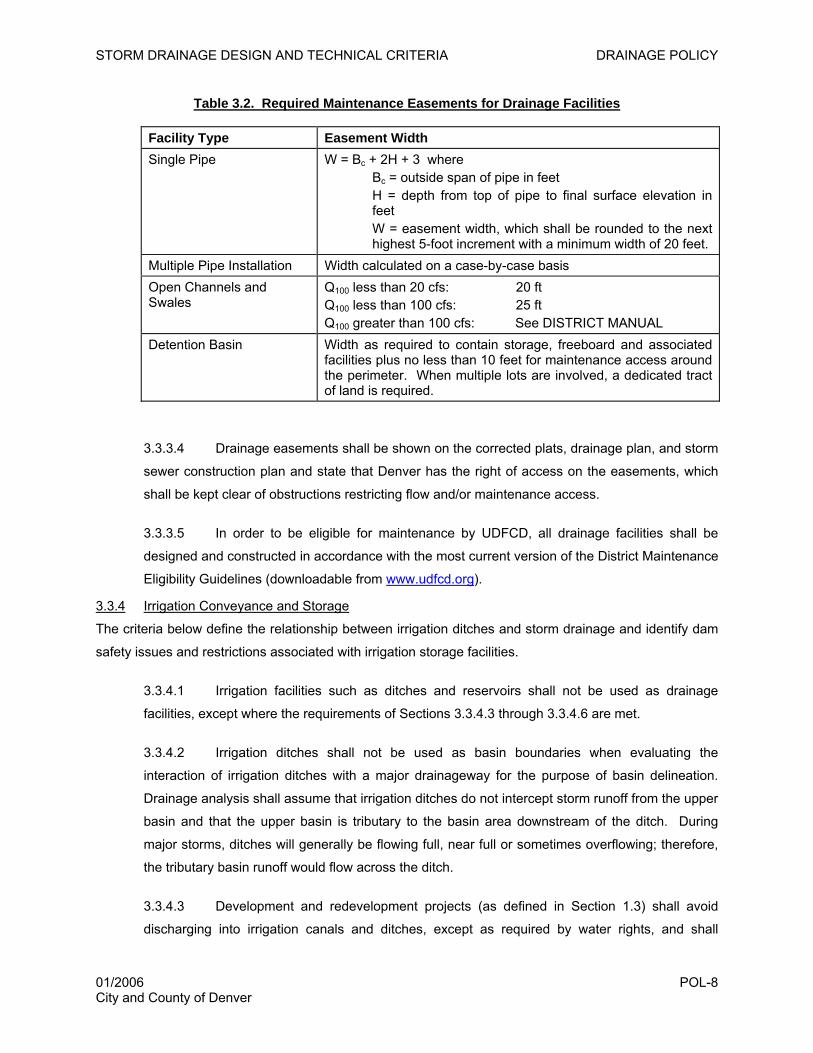
STORM DRAINAGE DESIGN AND TECHNICAL CRITERIA DRAINAGE POLICY
Table 3.2. Required Maintenance Easements for Drainage Facilities
Facility Type Easement Width Single Pipe W = Bc + 2H + 3 where
Bc = outside span of pipe in feet H = depth from top of pipe to final surface elevation in feet W = easement width, which shall be rounded to the next highest 5-foot increment with a minimum width of 20 feet.
Multiple Pipe Installation Width calculated on a case-by-case basis Open Channels and Swales
Q100 less than 20 cfs: 20 ft Q100 less than 100 cfs: 25 ft Q100 greater than 100 cfs: See DISTRICT MANUAL
Detention Basin Width as required to contain storage, freeboard and associated facilities plus no less than 10 feet for maintenance access around the perimeter. When multiple lots are involved, a dedicated tract of land is required.
3.3.3.4 Drainage easements shall be shown on the corrected plats, drainage plan, and storm
sewer construction plan and state that Denver has the right of access on the easements, which
shall be kept clear of obstructions restricting flow and/or maintenance access.
3.3.3.5 In order to be eligible for maintenance by UDFCD, all drainage facilities shall be
designed and constructed in accordance with the most current version of the District Maintenance
Eligibility Guidelines (downloadable from www.udfcd.org).
3.3.4 Irrigation Conveyance and Storage
The criteria below define the relationship between irrigation ditches and storm drainage and identify dam
safety issues and restrictions associated with irrigation storage facilities.
3.3.4.1 Irrigation facilities such as ditches and reservoirs shall not be used as drainage
facilities, except where the requirements of Sections 3.3.4.3 through 3.3.4.6 are met.
3.3.4.2 Irrigation ditches shall not be used as basin boundaries when evaluating the
interaction of irrigation ditches with a major drainageway for the purpose of basin delineation.
Drainage analysis shall assume that irrigation ditches do not intercept storm runoff from the upper
basin and that the upper basin is tributary to the basin area downstream of the ditch. During
major storms, ditches will generally be flowing full, near full or sometimes overflowing; therefore,
the tributary basin runoff would flow across the ditch.
3.3.4.3 Development and redevelopment projects (as defined in Section 1.3) shall avoid
discharging into irrigation canals and ditches, except as required by water rights, and shall
01/2006 POL-8 City and County of Denver
STORM DRAINAGE DESIGN AND TECHNICAL CRITERIA DRAINAGE POLICY
instead direct runoff into historic and natural drainageways. As a general rule, the flat slopes,
limited carrying capacities, and potential for abandonment of ditches make them inappropriate for
storm drainage usage.
3.3.4.4 Discharge of runoff into irrigation ditches shall be approved only under these
conditions:
1. The discharge is consistent with the relevant master drainage plan.
2. Thorough hydrologic and hydraulic analysis indicates the discharge is reasonable.
3. The owner’s liability for ditch failure is clearly defined.
4. Written consent of the ditch company is submitted.
5. The practice is determined to be in Denver’s best interest.
3.3.4.5 Whenever irrigation ditches cross major drainageways within a developing area, the
developer shall design and construct appropriate structures to separate storm runoff from ditch
flows.
3.3.4.6 Any modifications to existing topography or placement of drainage structures that
affect water quality and/or drainage patterns to ditches or other utilities shall comply with the
criteria listed in Section 3.3.4.4.
3.3.4.7 For hydrologic purposes, all private dams shall be ignored in the definition of
floodplains.
3.3.4.8 All development and redevelopment projects (as defined in Section 1.3) downstream
of irrigation storage facilities shall obtain flood hazard maps from the State Engineer’s Office to
determine dam hazard classifications pursuant to Section 37-87-123, CRS.
3.3.4.9 All development and redevelopment projects (as defined in Section 1.3) shall be
restricted to areas outside of the reservoir’s high water line based on the design flood for the
structure’s emergency spillway.
3.3.4.10 All development and redevelopment projects (as defined in Section 1.3) shall be
restricted to areas outside of the high water line based on the breach of a dam (except high
hazard classified dams which have passed inspection by the State Engineer’s office in
accordance with 37-87-105 et seq. CRS 1974).
01/2006 POL-9 City and County of Denver
STORM DRAINAGE DESIGN AND TECHNICAL CRITERIA DRAINAGE POLICY
3.3.4.11 All development and redevelopment (as defined in Section 1.3) shall be restricted to
areas outside existing or potential future emergency spillway paths, beginning at the dam and
proceeding to the point where the flood water returns to the natural drainage course.
3.3.5 Water Quality
3.3.5.1 All development and redevelopment (as defined in Section 1.3) shall comply with the
terms and conditions of Denver’s Colorado Discharge Permit System (CDPS) stormwater
discharge permit for the purpose of minimizing the discharge of pollutants to receiving waters to
the maximum extent practicable.
3.3.5.2 All development and redevelopment projects (as defined in Section 1.3) located
within Denver shall provide specific measures to enhance the water quality of storm-generated
runoff from the fully developed project site, as specified in Chapter 14 of these DENVER
CRITERIA. All BMPs identified in Volume 3 of the DISTRICT MANAUAL are applicable to all
development and redevelopment projects within Denver. Water quality BMPs shall be
implemented in accordance with the requirements of Chapter 14 of these DENVER CRITERIA.
3.3.5.3 All development and redevelopment projects (as defined in Section 1.3) located
within Denver are required to implement BMPs to control erosion, sedimentation, and pollutant
laden stormwater discharges during construction activities in accordance with Chapter 15 of
these DENVER CRITERIA and Volume 3 of the DISTRICT MANUAL.
3.3.5.4 Denver reserves the right to require implementation of temporary and permanent
BMPs on development and redevelopment sites less than one acre in size.
01/2006 POL-10 City and County of Denver
STORM DRAINAGE DESIGN AND TECHNICAL CRITERIA FLOODPLAIN REGULATIONS
4.0 FLOODPLAIN REGULATIONS
4.1 Introduction
The regulation of floodplains is necessary to preserve and promote the general health, welfare, and
economic well being of the region. The general purposes of floodplain regulations are summarized as
follows:
1. To reduce the hazard of floods to life and property.
2. To protect and preserve hydraulic characteristics of water courses used for conveyance of flood
waters.
3. To protect the public from extraordinary financial expenditures for flood control and relief.
Floodplains shall be regulated and managed in accordance with Denver’s Floodplain Ordinance (Article
V, Chapter 56, Revised Municipal Code), which is provided in Section 4.2 below. It is the designer’s
responsibility to use the most current adopted floodplain maps and to ensure compliance with the current
Denver ordinances and federal regulations. Floodplains shall be left in a natural state or used as open
space recreational areas to the maximum extent practicable. In essence, the Ordinance states that:
1. Construction within the floodway is prohibited.
2. Residential construction within the floodplain must elevate the lowest floor (including basement)
to or above the flood protection elevation.
3. Commercial or industrial development must elevate the lowest floor (including basement) or flood
proof to or above the flood protection elevation.
4. Flood protection elevation is 1.5 feet above the base flood elevation.
5. Elevation certificates are required for all structures built within floodplain boundaries as defined by
Federal Emergency Management Agency (FEMA) Flood Insurance Rate Maps.
6. Flood proofing must be approved by the Building Inspection Division.
In cases where the floodplain will be altered, it is the developer’s responsibility to first obtain a Conditional
Letter of Map Revision (CLOMR) early in the planning process and obtain a final Letter of Map Revision
(LOMR) when the project is complete. All analysis and associated costs are the responsibility of the
developer.
Denver encourages flood proofing of existing structures that are not in compliance with Denver’s
Floodplain Ordinance. Flood proofing shall be completed in accordance with the criteria specified in the
FLOOD PROOFING chapter of the DISTRICT MANUAL, the latest version of the Colorado Flood Proofing
Manual (CWCB 1983), the City and County of Denver Flood Protection Handbook (Denver and UDFCD
01/2006 FLD-1 City and County of Denver
STORM DRAINAGE DESIGN AND TECHNICAL CRITERIA FLOODPLAIN REGULATIONS
2003) and FEMA Guidance. Construction of critical facilities such as hospitals, nursing homes, schools
and fire stations in the floodplain must be avoided.
4.2 Denver Floodplain Ordinance
Sec. 56-200. Legislative intent.
(a) Findings of fact. Due to its general terrain and geographical location, the city is particularly subject
to damage from stormwaters, which, from time to time, overflow from existing watercourses and drainage
facilities, and imprudent use of these natural hazard areas called floodplains will pose a continuing and
greater danger to life and property in the future unless proper regulations are adopted.
(b) Statement of purpose. This article is enacted to promote the public health, safety, and general
welfare, and to minimize public and private losses due to flood conditions in specific areas, by provisions
designed to:
(1) Protect human life and health;
(2) Minimize expenditure of public money for costly flood control projects;
(3) Minimize the need for rescue and relief efforts associated with flooding and generally
undertaken at the expense of the general public;
(4) Minimize prolonged business interruptions;
(5) Minimize damage to public facilities and utilities such as water and gas mains, electric,
telephone and sewer lines, streets and bridges located in areas of special flood hazard;
(6) Help maintain a stable tax base by providing for the second use and development of areas
of special flood hazard so as to minimize future flood blight areas;
(7) Ensure that potential buyers are notified that property is in an area of special flood hazard;
(8) Ensure that those who occupy the areas of special flood hazards assume responsibility for
their actions;
(9) Encourage and facilitate urban water resources management techniques reduction of
pollution and the enhancement of the urban environment.
(c) Methods of reducing flood losses. In order to accomplish its purposes, this article:
(1) Requires that all construction of permitted buildings shall be in compliance with the Denver
Building Code;
01/2006 FLD-2 City and County of Denver
STORM DRAINAGE DESIGN AND TECHNICAL CRITERIA FLOODPLAIN REGULATIONS
(2) Restricts or prohibits uses which are dangerous to health, safety, and property due to water
or erosion hazards, or which result in damaging increases in erosion or in flood heights or
velocities;
(3) Requires that uses vulnerable to floods, including facilities which serve such uses, be
protected against flood damage at the time of initial construction;
(4) Controls the alteration of natural floodplains, stream channels, and natural protective
barriers, which help accommodate or channel floodwaters;
(5) Controls filling, grading, dredging, and other development which may increase flood
damage; and,
(6) Prevents or regulates the construction of flood barriers which will unnaturally divert
floodwaters or which may increase flood hazards in other areas.
(Ord. No. 158-86, § 1, 3-17-86)
Sec. 56-201. Definitions.
(a) Words, phrases and terms defined herein shall be given the defined meaning.
(b) Words, phrases and terms not defined herein, but defined in the building code or the zoning code of
the city, shall be construed as defined in such code.
(c) Words, phrases and terms neither defined herein nor in the building code or the zoning code of the
city, shall be given usual and customary meanings except where the context clearly indicates a different
meaning.
(d) The word "shall" is mandatory and not permissive; the word "may" is permissive and not mandatory.
Appeal: A request for a review of the interpretation of any provisions of this article.
Development: Any manmade change to improved or unimproved real estate, including but not limited to
buildings or other structures, mining, dredging, filling, grading, paving, excavation or drilling operations.
Encroachment lines: Limits of obstruction to flood flows. These lines are generally parallel to the stream.
The lines are established by assuming that the area landward (outside) of the encroachment lines may be
ultimately developed in such a way that it will not be available to convey flood flows. The stream channel
and adjoining floodplains between these lines will be maintained as open space and will be adequate to
convey the one-hundred-year flood without adversely increasing flood heights, such increase under any
condition not exceeding one (1) foot.
Equal degree of encroachment: Established by considering the effect of encroachments on the hydraulic
efficiency of the floodplain along a significant reach of the stream, on both sides.
01/2006 FLD-3 City and County of Denver
STORM DRAINAGE DESIGN AND TECHNICAL CRITERIA FLOODPLAIN REGULATIONS
Flood Insurance Rate Map (FIRM): The official map on which the Federal Emergency Management
Agency has delineated both the areas of special flood hazards and the risk premium zones applicable to
the community.
Flood Insurance Study: The official report in which the Federal Emergency Management Agency has
provided flood profiles, as well as the flood boundary-floodway map and the water surface elevation of the
one-hundred-year flood.
Floodplain: An area in and adjacent to a waterway or storm runoff channel, which is subject to a one-
hundred-year flood, and which area is so adverse to past, current or future construction or prudent land
use as to constitute a significant hazard to public health, safety or welfare.
Flood profile: A graph or longitudinal profile showing the relationship of the water surface elevation of a
flood event to a location along a stream or river.
Flood proofing: A combination of structural provisions, changes, or adjustments to properties and
structures subject to flooding primarily for the reduction or elimination of flood damages to properties,
water and sanitary facilities, structures, and contents of buildings in a flood hazard area.
Flood protection elevation: An elevation one and one-half (1.5) feet above the elevation or flood profile of
the hundred-year flood under existing channel and floodplain conditions.
Flood storage area: The fringe portion of the regulatory floodplain in which flows are characteristically of
shallow depths and low velocities.
Floodway: The channel of a river, creek or other watercourse and the adjacent land area that must be
reserved in order to discharge the hundred-year flood without cumulatively increasing the water surface
elevation more than one (1) foot assuming an equal degree of encroachment for a significant reach of
channel.
Manager of public works: Hereinafter called the manager, he shall be the officer in full charge and control
of the department of public works (refer to section 56-204(a)).
Occupancy: The use or possession of a building by humans for purposes including, but not limited to,
residential, office, hospital, or commercial.
One-hundred-year flood: A flood that has the frequency of occurrence of once every one hundred (100)
years determined from an analysis of floods on a particular watercourse and other watercourse and other
watercourses in the same general region. It was approximately a one (1) percent chance of occurring in
any given year.
Regulatory floodplain: That portion of the floodplain subject to inundation by the one-hundred-year flood.
01/2006 FLD-4 City and County of Denver
STORM DRAINAGE DESIGN AND TECHNICAL CRITERIA FLOODPLAIN REGULATIONS
Shallow flooding area: A designated AO zone on the flood insurance rate map (FIRM). The one-hundred-
year flood depths range from one (1) to three (3) feet; a clearly defined channel does not exist; the path of
flooding is unpredictable and indeterminate; and velocity flow may be evident.
Structure: Anything constructed or erected, the use of which requires a more or less permanent location
on or in the ground. It includes but is not limited to objects such as buildings, factories, sheds, and cabins.
Substantial improvement: Any repair, reconstruction, or improvement of a structure, the cost of which
equals or exceeds fifty (50) percent of the market value of the structure either, (a) before the improvement
or repair is started, or (b) if the structure has been damaged, and is being restored, before the damage
occurred. For the purposes of this definition "substantial improvement" is considered to occur when the
first alteration of any wall, ceiling, floor, or other structural part of the building commences, whether or not
that alteration affects the external dimensions of the structure. The term does not, however, include either
(1) any project for improvement of a structure to comply with existing state or local health, sanitary, or
safety code specifications which are solely necessary to assure safe living conditions or (2) any alteration
of a structure listed on the National Register of Historic Places or a state inventory of historic places.
Use: The purpose for which land or structures thereon is designed, arranged or intended to be occupied
or used, or for which it is occupied, maintained, rented or leased.
Variance: A grant of relief from the requirements of this article which permits construction in an area that
would otherwise be prohibited by this article.
(Ord. No. 158-86, § 1, 3-17-86)
Sec. 56-202. General provisions.
(a) Disclaimer of liability. The degree of flood protection required by this article is considered
reasonable for regulatory purposes and is based on scientific and engineering considerations. Larger
floods can and will occur on rare occasions. Flood heights may be increased by manmade or natural
causes. This article does not imply that land outside the areas of special flood hazards or uses permitted
within such areas will be free from flooding or flood damages. This article shall not create liability on the
part of the city, any officer or employee thereof, or the Federal Emergency Management Agency (FEMA),
for any flood damages that result from reliance on this article or any administrative decision lawfully made
thereunder.
(b) Jurisdiction of this article. The provisions of this article apply to all lands, uses and structures in all
areas of the city located within a regulatory floodplain as defined in section 56-201, "Definitions," of this
article.
(c) Interpretation. In the interpretation and application of this article, all provisions shall be:
(1) Considered as minimum requirements;
01/2006 FLD-5 City and County of Denver
STORM DRAINAGE DESIGN AND TECHNICAL CRITERIA FLOODPLAIN REGULATIONS
(2) Liberally construed in favor of the governing body; and,
(3) Deemed neither to limit nor repeal any other powers granted under state statutes.
(d) Floodplains.
(1) Regulatory floodplains. Regulatory floodplains shall be those areas of special flood hazard
which, among others, are identified by FEMA in scientific and engineering reports which are done
periodically, which in the past have been entitled "Flood Insurance Study for the City and County
of Denver," and which are accompanied by flood insurance rate maps (FIRM) and flood
boundary-floodway maps. The regulatory floodplain shall be subdivided into the floodway and the
floodway storage area as defined in section 56-201, definitions, of this article.
(2) Zone A. When one-hundred-year flood elevation data has not been provided in accordance
with the foregoing paragraph, and an area of special flood hazard has been designated zone A,
the deputy manager of public works for wastewater management shall obtain, review and
reasonably utilize any one-hundred-year flood elevation data available from federal, state or other
source in order to administer the applicable conditions of section 56-203, "Floodplain use and
limitations," of this article.
(e) Adoption of floodplain map.
(1) The maps which define the floodplains established by this article shall be adopted by the
manager of public works. Such adoption shall be accomplished by:
a. Filing one (1) copy thereof with the city clerk;
b. Filing one (1) copy thereof with the city attorney;
c. Concurrently with the filings required under a. and b., above, the manager of public
works shall publish a notice stating that the filings have been made and list the dates of
such filings. Such notice shall be published once in the official newspaper.
(2) The adopted maps collectively shall constitute the official floodplain map.
(3) The various individual floodplain maps constituting the official floodplain map shall be
marked and maintained pursuant to a system of identification established by the wastewater
management division of the department of public works.
(4) The manager and his designee shall make all maps available to public inspection at all
reasonable times.
(f) Amendments to official floodplain map.
01/2006 FLD-6 City and County of Denver
STORM DRAINAGE DESIGN AND TECHNICAL CRITERIA FLOODPLAIN REGULATIONS
(1) Upon the recommendation of the deputy manager of public works for wastewater
management, amendments of whatsoever nature to the official floodplain map shall be referred to
the manager of public works for adoption. Amendments shall be adopted as in paragraph (e)
above.
(2) Those individual maps constituting a part of the official floodplain map which were
originated by FEMA, shall only be amended by the manager of public works following FEMA
review and approval of data submitted by the city, and subsequent amendment by FEMA thereof.
(3) All amendments to the official floodplain map shall be listed in the order in which they were
adopted, in a separate register maintained in and kept current by the wastewater management
division of the department of public works.
(g) Effect of other ordinances and regulations. Wherever higher or more restrictive standards are
established by the provisions of any other applicable statute, ordinance or regulation than are established
by the provisions of this article, the provisions of such other statute, ordinance or regulation shall govern.
(h) Effect of private covenants. Nothing herein contained shall be construed to render inoperative any
restrictions established by covenants running with the land unless such are prohibited by or are contrary
to the provisions of this article.
(i) Floodplain disclaimer. As a part of the sale of any property within the city, a disclaimer shall be
provided to the potential buyer by the seller indicating the relationship of the property to any regulatory
floodplain.
(Ord. No. 158-86, § 1, 3-17-86; Ord. No. 711-94, § 1, 9-6-94)
Sec. 56-203. Floodplain use and limitations.
(a) General. The following provisions shall apply to all uses within all areas of floodplains as defined
and adopted under section 56-202(d) and (e) of this article.
(b) Existing uses. An existing use in a floodplain may be changed to any use which is allowed by the
ordinances of the city; provided, however, that such change of an existing use shall be limited by and
shall be in accordance with the regulations herein established.
(c) Regulatory floodplain. In all areas of special flood hazards where one-hundred-year flood elevation
data has been provided, the following provisions are required:
(1) No development, use, fill, excavation, construction or alteration within a floodplain shall be
permitted, which acting alone or in combination with existing or future uses, would cause or result
in any of the following:
01/2006 FLD-7 City and County of Denver
STORM DRAINAGE DESIGN AND TECHNICAL CRITERIA FLOODPLAIN REGULATIONS
a. The storage or processing of materials that are buoyant, flammable, explosive or
otherwise potentially injurious to human, animal or plant life in time of flooding;
b. The disposal of garbage, sludge, waste materials or other potentially injurious
substances in the floodplain;
c. An obstruction or depositing of any material which would impair the flow capacity of
a floodplain or increase floodwater depths or velocities so as to cause probable damage
to others wherever located;
d. A substantial increase in sedimentation and/or erosion.
(2) All new construction, substantial improvement and/or remodeling of existing construction
shall be approved by the wastewater management division for location and shall comply with the
requirements of Section 1723 of the Denver Building Code.
(3) On-site waste disposal systems shall be located to avoid impairment to them or
contamination from them during flooding.
(4) No mobile home shall be located in the regulatory floodplain.
(5) Permitted uses: The following uses shall be permitted within the regulatory floodplain to the
extent that they will comply with all requirements of the zoning ordinance:
a. Agricultural uses such as general farming, pasture, grazing, outdoor plant nurseries,
horticulture, truck farming, forestry, sod farming and wild crop harvesting;
b. Uses such as loading areas, parking areas, airport landing strips and storage yards
for equipment or machinery easily removed from the site or not subject to flood damage;
c. Private and public recreational uses such as parks, golf courses, driving ranges,
archery ranges, picnic grounds, boat launching ramps, and hiking, biking and horseback
riding trails;
d. Utility facilities including, but not limited to, wastewater facilities, water, gas and
electric distribution facilities, roadways and bridges;
e. Fill, excavation or deposit of materials:
1. Any such fill, excavation or deposit of materials shall be permitted only upon
a finding that the fill, excavation or deposit of materials will have some beneficial
purpose and the amount thereof will not be greater than is necessary to achieve
that purpose, as demonstrated by a plan submitted by the owner showing the
01/2006 FLD-8 City and County of Denver
STORM DRAINAGE DESIGN AND TECHNICAL CRITERIA FLOODPLAIN REGULATIONS
final dimensions of the proposed fill, excavation or material and the use to which
the altered land will be put;
2. The fill or material does not encroach on the floodway;
3. Any fill or deposit that reduces the hydraulic capacity shall require
appropriate hydraulic studies and a review of the urban impact on such
reduction;
4. The fill or material will be protected against erosion by rip-rap, strong
vegetative cover or bulkheading.
(d) The floodway. The floodway is an extremely hazardous area due to the velocity of floodwaters
which carry debris, potential projectiles, and erosion potential. In addition to section 56-203(c), the
following provisions shall also apply to all uses within the floodway:
(1) No encroachments, including fill, new construction, substantial improvements, or other
development shall be permitted within the floodway that would result in any increase in flood
levels during the occurrence of the one-hundred-year flood.
(2) No building designed for human occupancy shall be placed in the floodway.
(e) Flood storage area. In addition to the provisions of section 56-203(c), the following requirements
shall also apply to all uses in the flood storage area:
(1) Residential construction. New construction, substantial improvement and/or remodeling of
any residential structure shall have the lowest floor, including basement, elevated a minimum of
one and one-half (1.5) feet above the one-hundred-year flood elevation.
New construction, substantial improvement and/or remodeling of any residential structure within
an area designated as an AO zone on the FIRM shall have the lowest floor, including basement,
elevated above the highest adjacent grade at least as high as the depth number specified in feet
on the community's FIRM (at least two (2) feet if no depth number is specified).
(2) Nonresidential construction. New construction, substantial improvement and/or remodeling
of any commercial, industrial or other nonresidential structure shall either have the lowest floor,
including basement, elevated a minimum of one and one-half (1.5) feet above the level of the
one-hundred-year flood elevation; or, together with attendant utility and sanitary facilities, shall
comply with Section 1723 of the Denver Building Code.
New construction, substantial improvement and/or remodeling of any commercial, industrial or
other nonresidential structure within an area designated as an AO zone on the FIRM shall either
have the lowest floor, including basement, elevated above the highest adjacent grade at least as
01/2006 FLD-9 City and County of Denver
STORM DRAINAGE DESIGN AND TECHNICAL CRITERIA FLOODPLAIN REGULATIONS
high as the depth number specified in feet on the community's FIRM (at least two (2) feet if no
depth number is specified); or, together with attendant utility and sanitary facilities, shall comply
with Section 1723 of the Denver Building Code.
(Ord. No. 158-86, § 1, 3-17-86)
Sec. 56-204. Administration.
(a) Administration of article by manager of public works. The administration of the provisions of this
article is hereby vested in and shall be exercised by the manager of the department of public works who
may, in accordance with article VI of chapter 2 of the Revised Municipal Code, prescribe forms and rules
and regulations in conformity with this article for the proper administration and enforcement hereof. The
manager of public works may delegate the administration of this article or any part thereof, subject to the
limitations of the Charter and this Code, to duly qualified deputies and agents of the manager of public
works. For the purposes of this article, the manager of public works shall delegate the administration
thereof to the deputy manager of public works for wastewater management except section 56-202(e)(1),
"Adoption of floodplain map," and section 56-204(e), "Administrative review."
(b) Responsibilities of land developers.
(1) Each developer of land within the city has a duty to provide on his/her property all
reasonably necessary drainage and detention facilities to ensure the adequate drainage and
control of stormwaters which fall on his/her properties or which contribute runoff to his/her
property.
(2) A storm drainage plan shall be submitted and approved prior to issuing a wastewater permit
for new construction, substantial improvement and/or remodeling of a building located in a
regulatory floodplain. Such plan shall be reviewed with regard for generally accepted engineering
principles and standards as follows:
a. The storm drainage plan shall provide the base flood elevations for those areas
where no base flood elevation had previously been provided, and shall define the
alignment and boundary of any natural drainage course, drainage facility or subdrainage
area on the land in question, and it shall include drawings, profiles, specifications for the
construction of channels, conduits, detention basins, culverts, bridges and all other
drainage facilities reasonably necessary to ensure that flood and stormwaters, including
drainage from other lands which will contribute runoff to the subject property, will be
adequately drained, stored, or otherwise controlled; plans drawn to scale showing the
nature, location, dimensions, and elevations of the area in question; size and location of
existing and/or proposed structures, fill, storage of materials, drainage facilities; floodplain
area and the location of the foregoing. Specifically, the following information is required:
01/2006 FLD-10 City and County of Denver
STORM DRAINAGE DESIGN AND TECHNICAL CRITERIA FLOODPLAIN REGULATIONS
1. Elevation in relation to mean sea level of the lowest floor (including
basement) of all structures;
2. Description of the extent to which any watercourse will be altered or
relocated as a result of proposed development.
b. Included in the plan shall be a schedule containing the estimated dates of
completion of construction for all storm drainage facilities shown on the plat. If and when
the plan is approved and the wastewater permit issued, the owner and applicant shall
comply with said schedule.
(3) Any improvements to an existing drainageway which will result in a change of the regulatory
floodplain will be constructed consistent with applicable city criteria and standards. Development
within the regulatory floodplain will not be permitted until the approved drainage improvements
have been constructed and the amended floodplain maps have been approved by FEMA and
adopted by the city.
(c) Boundary mapping disputes. The boundaries of the regulatory floodplain shall be as they appear on
the floodplain maps filed with the clerk and recorder. Where there appears to be a conflict between the
boundary lines illustrated on the map and actual field conditions, the person contesting the location of the
boundary shall be given an opportunity to submit his own technical evidence.
No deviation from the boundary line as mapped shall be allowed unless the evidence clearly and
conclusively establishes that the mapped location of the line is incorrect. However, if the evidence
submitted, after review, clearly shows that the recorded boundary does not reflect the true condition, an
exception will be granted. If the location of the boundary line should still be in dispute, that person may
appeal as provided in section 56-204(e).
(d) Variances.
(1) The deputy manager of public works for wastewater management (deputy) may authorize,
upon application in specific cases, such variances from the terms of this article, subject to terms
and conditions fixed by the deputy, as will not be contrary to the purposes of this article where,
owing to exceptional and extraordinary circumstances, literal enforcement of the provisions of this
article will result in unnecessary hardship. No variance shall be authorized hereunder unless the
deputy shall find:
a. The variance will not result in an increase in the flood levels in a designated
floodway during a one-hundred-year flood discharge;
b. The variance is the minimum necessary to afford relief considering the flood hazard;
01/2006 FLD-11 City and County of Denver
STORM DRAINAGE DESIGN AND TECHNICAL CRITERIA FLOODPLAIN REGULATIONS
c. The variance will not result in an increased risk to public safety, a substantial
increase in public expense or a nuisance;
d. The lowest floor, including the basement, of any residential structure will be elevated
a minimum of one and one-half (1.5) feet above the level of the one-hundred-year flood;
e. The proposed change or development will not unreasonably endanger the life,
health, safety, welfare or property of any person in time of floods, or result in the
damming of floodwaters or the contribution of potentially damaging debris to floodwaters;
f. The use requested is a permitted use under the zoning ordinance;
g. The applicant is the owner of the subject property;
h. The new construction, substantial improvement, and/or remodeling of any structure
on a lot of one-half acre or less in size, is contiguous to and surrounded by lots with
existing structures constructed below the base flood level. As the lot size increases
beyond the one-half acre, increased technical justification is required for issuing the
variance.
(2) The following matters shall be considered by the deputy in determining all applications for
variances:
a. The danger that materials may be swept onto other lands to the injury of others;
b. The danger to life and property due to flooding or erosion damage;
c. The susceptibility of the proposed facility and its contents to flood damage and the
effect of such damage on the individual owner;
d. The importance of the services provided by the proposed facility to the community;
e. The necessity to the facility of a waterfront location where applicable;
f. The availability of alternative locations, for the proposed use which are not subject to
flooding or erosion damage;
g. The compatibility of the proposed use with the existing and anticipated development;
h. The relationship of the proposed use to the comprehensive plan and floodplain
management program for that area;
i. The safety of access to the property in times of flood for ordinary and emergency
vehicles;
01/2006 FLD-12 City and County of Denver
STORM DRAINAGE DESIGN AND TECHNICAL CRITERIA FLOODPLAIN REGULATIONS
j. The expected height, velocity, duration, rate of rise, and sediment transport of the
floodwaters and the effects of wave action, if applicable, expected at the site;
k. The costs of providing governmental services during and after flood conditions
including maintenance and repair of public utilities and facilities such as sewer, gas,
electrical, and water systems, and streets and bridges.
(3) Each and every application for a variance shall contain adequate technical information
certified by a professional engineer licensed in the state which shall include, unless waived in
writing by the deputy, the following:
a. A certified topographic survey by a licensed land surveyor of the applicant's property
and surrounding areas that may be affected by any proposed change; said survey data
shall include plan, profile and cross-sections showing accurate elevations of all points,
based upon United States Geological Survey datum, within the limits of flooding under
both existing and proposed conditions;
b. Drawings and descriptions of any proposed change to ground surface, topography
or natural features or any proposed construction or modification of any structure or facility
within a floodplain;
c. Drawings and descriptions defining the probable behavior of floodwaters across and
in the vicinity of the applicant's property and for a reasonable distance upstream and
downstream, under both existing and proposed conditions; together with all supporting
hydrologic data and hydraulic analysis, computations, backwater curves, flow quantities
and approximate velocities;
d. Any other information either the applicant or the deputy manager of public works for
waste water management may deem necessary to a thorough and informed evaluation of
the proposed activity;
(4) Any applicant to whom a variance is granted shall be given written notice that the structure
will be permitted to be built, substantially improved or remodeled with a lowest floor elevation
below the one-hundred-year flood elevation and that the cost of flood insurance will be
commensurate with the increased risk resulting from the reduced lowest story elevation.
(5) The deputy shall maintain the records of all appeal actions and report the issuance of any
variance to FEMA upon request.
(e) Administrative review.
(1) Any person who disputes any determination made by or on behalf of the city pursuant to
and by authority of the manager, which determination adversely affects such person, may petition
01/2006 FLD-13 City and County of Denver
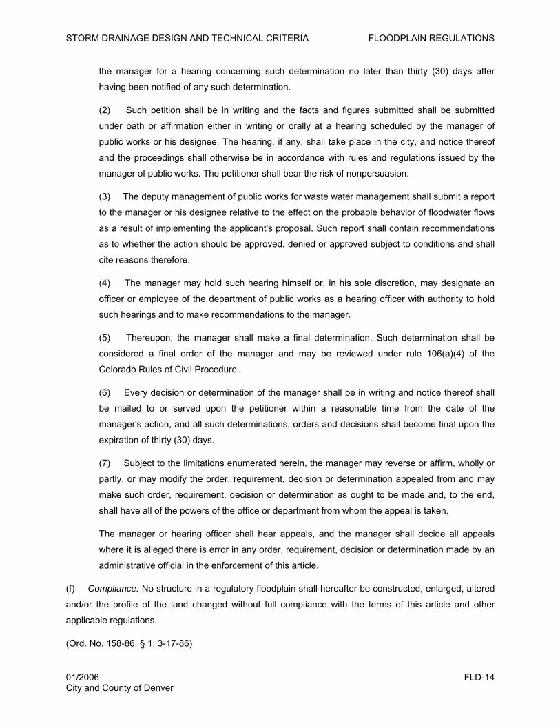
STORM DRAINAGE DESIGN AND TECHNICAL CRITERIA FLOODPLAIN REGULATIONS
the manager for a hearing concerning such determination no later than thirty (30) days after
having been notified of any such determination.
(2) Such petition shall be in writing and the facts and figures submitted shall be submitted
under oath or affirmation either in writing or orally at a hearing scheduled by the manager of
public works or his designee. The hearing, if any, shall take place in the city, and notice thereof
and the proceedings shall otherwise be in accordance with rules and regulations issued by the
manager of public works. The petitioner shall bear the risk of nonpersuasion.
(3) The deputy management of public works for waste water management shall submit a report
to the manager or his designee relative to the effect on the probable behavior of floodwater flows
as a result of implementing the applicant's proposal. Such report shall contain recommendations
as to whether the action should be approved, denied or approved subject to conditions and shall
cite reasons therefore.
(4) The manager may hold such hearing himself or, in his sole discretion, may designate an
officer or employee of the department of public works as a hearing officer with authority to hold
such hearings and to make recommendations to the manager.
(5) Thereupon, the manager shall make a final determination. Such determination shall be
considered a final order of the manager and may be reviewed under rule 106(a)(4) of the
Colorado Rules of Civil Procedure.
(6) Every decision or determination of the manager shall be in writing and notice thereof shall
be mailed to or served upon the petitioner within a reasonable time from the date of the
manager's action, and all such determinations, orders and decisions shall become final upon the
expiration of thirty (30) days.
(7) Subject to the limitations enumerated herein, the manager may reverse or affirm, wholly or
partly, or may modify the order, requirement, decision or determination appealed from and may
make such order, requirement, decision or determination as ought to be made and, to the end,
shall have all of the powers of the office or department from whom the appeal is taken.
The manager or hearing officer shall hear appeals, and the manager shall decide all appeals
where it is alleged there is error in any order, requirement, decision or determination made by an
administrative official in the enforcement of this article.
(f) Compliance. No structure in a regulatory floodplain shall hereafter be constructed, enlarged, altered
and/or the profile of the land changed without full compliance with the terms of this article and other
applicable regulations.
(Ord. No. 158-86, § 1, 3-17-86)
01/2006 FLD-14 City and County of Denver
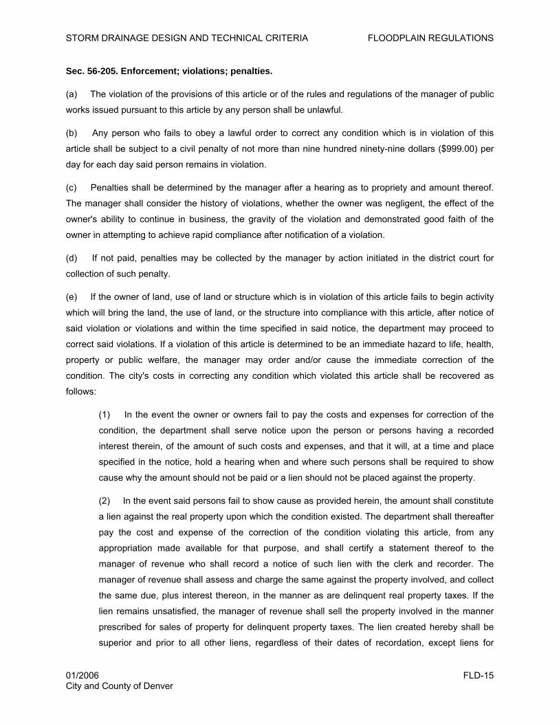
STORM DRAINAGE DESIGN AND TECHNICAL CRITERIA FLOODPLAIN REGULATIONS
Sec. 56-205. Enforcement; violations; penalties.
(a) The violation of the provisions of this article or of the rules and regulations of the manager of public
works issued pursuant to this article by any person shall be unlawful.
(b) Any person who fails to obey a lawful order to correct any condition which is in violation of this
article shall be subject to a civil penalty of not more than nine hundred ninety-nine dollars ($999.00) per
day for each day said person remains in violation.
(c) Penalties shall be determined by the manager after a hearing as to propriety and amount thereof.
The manager shall consider the history of violations, whether the owner was negligent, the effect of the
owner's ability to continue in business, the gravity of the violation and demonstrated good faith of the
owner in attempting to achieve rapid compliance after notification of a violation.
(d) If not paid, penalties may be collected by the manager by action initiated in the district court for
collection of such penalty.
(e) If the owner of land, use of land or structure which is in violation of this article fails to begin activity
which will bring the land, the use of land, or the structure into compliance with this article, after notice of
said violation or violations and within the time specified in said notice, the department may proceed to
correct said violations. If a violation of this article is determined to be an immediate hazard to life, health,
property or public welfare, the manager may order and/or cause the immediate correction of the
condition. The city's costs in correcting any condition which violated this article shall be recovered as
follows:
(1) In the event the owner or owners fail to pay the costs and expenses for correction of the
condition, the department shall serve notice upon the person or persons having a recorded
interest therein, of the amount of such costs and expenses, and that it will, at a time and place
specified in the notice, hold a hearing when and where such persons shall be required to show
cause why the amount should not be paid or a lien should not be placed against the property.
(2) In the event said persons fail to show cause as provided herein, the amount shall constitute
a lien against the real property upon which the condition existed. The department shall thereafter
pay the cost and expense of the correction of the condition violating this article, from any
appropriation made available for that purpose, and shall certify a statement thereof to the
manager of revenue who shall record a notice of such lien with the clerk and recorder. The
manager of revenue shall assess and charge the same against the property involved, and collect
the same due, plus interest thereon, in the manner as are delinquent real property taxes. If the
lien remains unsatisfied, the manager of revenue shall sell the property involved in the manner
prescribed for sales of property for delinquent property taxes. The lien created hereby shall be
superior and prior to all other liens, regardless of their dates of recordation, except liens for
01/2006 FLD-15 City and County of Denver
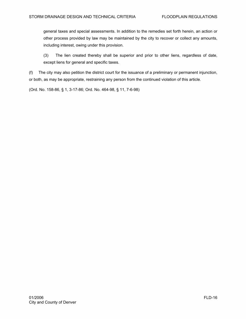
STORM DRAINAGE DESIGN AND TECHNICAL CRITERIA FLOODPLAIN REGULATIONS
general taxes and special assessments. In addition to the remedies set forth herein, an action or
other process provided by law may be maintained by the city to recover or collect any amounts,
including interest, owing under this provision.
(3) The lien created thereby shall be superior and prior to other liens, regardless of date,
except liens for general and specific taxes.
(f) The city may also petition the district court for the issuance of a preliminary or permanent injunction,
or both, as may be appropriate, restraining any person from the continued violation of this article.
(Ord. No. 158-86, § 1, 3-17-86; Ord. No. 464-98, § 11, 7-6-98)
01/2006 FLD-16 City and County of Denver
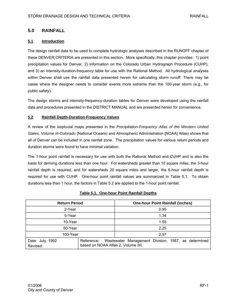
STORM DRAINAGE DESIGN AND TECHNICAL CRITERIA RAINFALL
5.0 RAINFALL
5.1 Introduction
The design rainfall data to be used to complete hydrologic analyses described in the RUNOFF chapter of
these DENVER CRITERIA are presented in this section. More specifically, this chapter provides: 1) point
precipitation values for Denver, 2) information on the Colorado Urban Hydrograph Procedure (CUHP),
and 3) an intensity-duration-frequency table for use with the Rational Method. All hydrological analyses
within Denver shall use the rainfall data presented herein for calculating storm runoff. There may be
cases where the designer needs to consider events more extreme than the 100-year storm (e.g., for
public safety).
The design storms and intensity-frequency-duration tables for Denver were developed using the rainfall
data and procedures presented in the DISTRICT MANUAL and are presented herein for convenience.
5.2 Rainfall Depth-Duration-Frequency Values
A review of the isopluvial maps presented in the Precipitation-Frequency Atlas of the Western United
States, Volume III-Colorado (National Oceanic and Atmospheric Administration [NOAA] Atlas) shows that
all of Denver can be included in one rainfall zone. The precipitation values for various return periods and
duration storms were found to have minimal variation.
The 1-hour point rainfall is necessary for use with both the Rational Method and CUHP and is also the
basis for deriving durations less than one hour. For watersheds greater than 10 square miles, the 3-hour
rainfall depth is required, and for watersheds 20 square miles and larger, the 6-hour rainfall depth is
required for use with CUHP. One-hour point rainfall values are summarized in Table 5.1. To obtain
durations less than 1 hour, the factors in Table 5.2 are applied to the 1-hour point rainfall.
Table 5.1. One-hour Point Rainfall Depths
Return Period One-hour Point Rainfall (inches) 2-Year 0.95 5-Year 1.34 10-Year 1.55 50-Year 2.25
100-Year 2.57 Date: July, 1992 Revised:
Reference: Wastewater Management Division, 1987, as determined based on NOAA Atlas 2, Volume IIII.
01/2006 RF-1 City and County of Denver
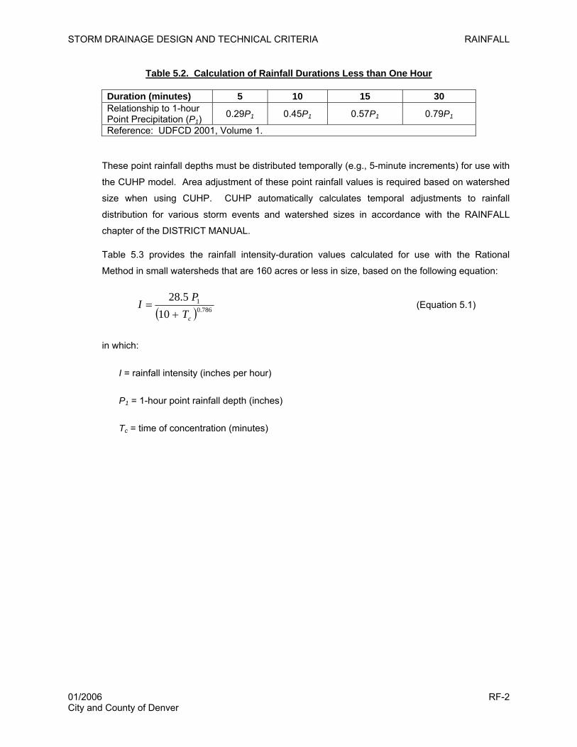
STORM DRAINAGE DESIGN AND TECHNICAL CRITERIA RAINFALL
Table 5.2. Calculation of Rainfall Durations Less than One Hour
Duration (minutes) 5 10 15 30 Relationship to 1-hour Point Precipitation (P1)
0.29P1 0.45P1 0.57P1 0.79P1
Reference: UDFCD 2001, Volume 1.
These point rainfall depths must be distributed temporally (e.g., 5-minute increments) for use with
the CUHP model. Area adjustment of these point rainfall values is required based on watershed
size when using CUHP. CUHP automatically calculates temporal adjustments to rainfall
distribution for various storm events and watershed sizes in accordance with the RAINFALL
chapter of the DISTRICT MANUAL.
Table 5.3 provides the rainfall intensity-duration values calculated for use with the Rational
Method in small watersheds that are 160 acres or less in size, based on the following equation:
( ) 786.01
105.28
cTPI
+= (Equation 5.1)
in which:
I = rainfall intensity (inches per hour)
P1 = 1-hour point rainfall depth (inches)
Tc = time of concentration (minutes)
01/2006 RF-2 City and County of Denver

STORM DRAINAGE DESIGN AND TECHNICAL CRITERIA RAINFALL
Table 5.3. Rainfall Intensity Duration Values for Use with the Rational Method
Time Rainfall Intensity in Inches per Hour Time Rainfall Intensity in Inches per Hour Min. 2-yr 5-yr 10-yr 50-yr 100-yr Min. 2-yr 5-yr 10-yr 50-yr 100-yr
5 3.22 4.55 5.26 7.63 8.72 35 1.36 1.92 2.22 3.22 3.68 10 2.57 3.63 4.19 6.09 6.95 36 1.34 1.88 2.18 3.16 3.61 11 2.47 3.49 4.04 5.86 6.69 37 1.31 1.85 2.14 3.11 3.55 12 2.38 3.36 3.89 5.65 6.45 38 1.29 1.82 2.11 3.06 3.49 13 2.30 3.25 3.76 5.45 6.23 39 1.27 1.79 2.07 3.01 3.44 14 2.23 3.14 3.63 5.27 6.02 40 1.25 1.76 2.04 2.96 3.38 15 2.16 3.04 3.52 5.11 5.83 41 1.23 1.74 2.01 2.92 3.33 16 2.09 2.95 3.41 4.95 5.66 42 1.21 1.71 1.98 2.87 3.28 17 2.03 2.86 3.31 4.81 5.49 43 1.19 1.69 1.95 2.83 3.23 18 1.97 2.78 3.22 4.67 5.34 44 1.18 1.66 1.92 2.79 3.19 19 1.92 2.71 3.13 4.55 5.19 45 1.16 1.64 1.89 2.75 3.14 20 1.87 2.64 3.05 4.43 5.06 46 1.14 1.61 1.87 2.71 3.10 21 1.82 2.57 2.97 4.31 4.93 47 1.13 1.59 1.84 2.67 3.05 22 1.78 2.51 2.90 4.21 4.81 48 1.11 1.57 1.82 2.64 3.01 23 1.73 2.45 2.83 4.11 4.69 49 1.10 1.55 1.79 2.60 2.97 24 1.69 2.39 2.76 4.01 4.58 50 1.08 1.53 1.77 2.57 2.93 25 1.66 2.34 2.70 3.92 4.48 51 1.07 1.51 1.75 2.53 2.89 26 1.62 2.28 2.64 3.84 4.38 52 1.06 1.49 1.72 2.50 2.86 27 1.58 2.24 2.59 3.75 4.29 53 1.04 1.47 1.70 2.47 2.82 28 1.55 2.19 2.53 3.68 4.20 54 1.03 1.45 1.68 2.44 2.79 29 1.52 2.14 2.48 3.60 4.11 55 1.02 1.44 1.66 2.41 2.75 30 1.49 2.10 2.43 3.53 4.03 56 1.01 1.42 1.64 2.38 2.72 31 1.46 2.06 2.39 3.46 3.95 57 0.99 1.40 1.62 2.35 2.69 32 1.43 2.02 2.34 3.40 3.88 58 0.98 1.39 1.60 2.33 2.66 33 1.41 1.99 2.30 3.34 3.81 59 0.97 1.37 1.58 2.30 2.63 34 1.38 1.95 2.26 3.28 3.74 60 0.96 1.35 1.57 2.27 2.60
Date: Jan 2006 Revised:
Calculated based on Equation 5.1.
01/2006 RF-3 City and County of Denver
STORM DRAINAGE DESIGN AND TECHNICAL CRITERIA RAINFALL
This page intentionally left blank.
01/2006 RF-4 City and County of Denver
STORM DRAINAGE DESIGN AND TECHNICAL CRITERIA RUNOFF
6.0 RUNOFF
6.1 Introduction
Proper calculation of runoff is critical to proper planning and sizing of storm drainage facilities.
Erroneously high runoff calculations can result in higher cost facilities, while erroneously low runoff
calculations can result in damage or loss of infrastructure, life, property and natural resources. This
chapter identifies the methodology to be used for determining the storm runoff design peaks and volumes
for preparation of storm drainage studies, plans, and facility designs in Denver. The background,
equations, examples, and spreadsheets (e.g., UD Rational) for these methods should be obtained from
the RUNOFF Chapter of the DISTRICT MANUAL. The Colorado Urban Hydrograph Procedure (CUHP)
and the Stormwater Management Model (SWMM) computer models for calculating and routing runoff may
be downloaded from the Urban Drainage and Flood Control District (UDFCD) website (www.udfcd.org).
6.2 Runoff Calculation Methods
There are several methods for calculating runoff acceptable for use in Denver: the Rational Method,
CUHP, and CUHP combined with SWMM, as described in Table 6.1. In some cases, UDFCD and/or
Denver have completed detailed hydrologic studies that may also be used. Criteria determining
appropriateness of use are also summarized in Table 6.1. All criteria specified in the DISTRICT MANUAL
must be followed for preparation of drainage reports and storm drainage facility designs in Denver.
01/2006 RO-1 City and County of Denver
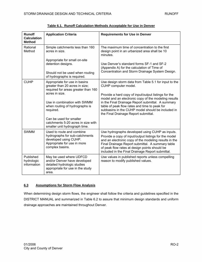
STORM DRAINAGE DESIGN AND TECHNICAL CRITERIA RUNOFF
Table 6.1. Runoff Calculation Methods Acceptable for Use in Denver
Runoff Calculation Method
Application Criteria Requirements for Use in Denver
Rational Method
Simple catchments less than 160 acres in size. Appropriate for small on-site detention designs. Should not be used when routing of hydrographs is required.
The maximum time of concentration to the first design point in an urbanized area shall be 10 minutes. Use Denver’s standard forms SF-1 and SF-2 (Appendix A) for the calculation of Time of Concentration and Storm Drainage System Design.
CUHP Appropriate for use in basins greater than 20 acres in size; required for areas greater than 160 acres in size. Use in combination with SWMM when routing of hydrographs is required. Can be used for smaller catchments 5-20 acres in size with smaller unit hydrograph time.
Use design storm data from Table 5.1 for input to the CUHP computer model. Provide a hard copy of input/output listings for the model and an electronic copy of the modeling results in the Final Drainage Report submittal. A summary table of peak flow rates and time to peak for subbasins in the CUHP model should be included in the Final Drainage Report submittal.
SWMM Used to route and combine hydrographs for sub-catchments developed using CUHP. Appropriate for use in more complex basins.
Use hydrographs developed using CUHP as inputs. Provide a copy of input/output listings for the model and an electronic copy of the modeling results in the Final Drainage Report submittal. A summary table of peak flow rates at design points should be included in the Final Drainage Report submittal.
Published hydrologic information
May be used where UDFCD and/or Denver have developed detailed hydrologic studies appropriate for use in the study area.
Use values in published reports unless compelling reason to modify published values.
6.3 Assumptions for Storm Flow Analysis
When determining design storm flows, the engineer shall follow the criteria and guidelines specified in the
DISTRICT MANUAL and summarized in Table 6.2 to assure that minimum design standards and uniform
drainage approaches are maintained throughout Denver.
01/2006 RO-2 City and County of Denver
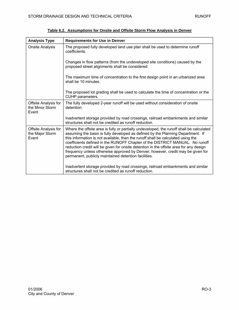
STORM DRAINAGE DESIGN AND TECHNICAL CRITERIA RUNOFF
Table 6.2. Assumptions for Onsite and Offsite Storm Flow Analysis in Denver
Analysis Type Requirements for Use in Denver Onsite Analysis The proposed fully developed land use plan shall be used to determine runoff
coefficients. Changes in flow patterns (from the undeveloped site conditions) caused by the proposed street alignments shall be considered. The maximum time of concentration to the first design point in an urbanized area shall be 10 minutes. The proposed lot grading shall be used to calculate the time of concentration or the CUHP parameters.
Offsite Analysis for the Minor Storm Event
The fully developed 2-year runoff will be used without consideration of onsite detention. Inadvertent storage provided by road crossings, railroad embankments and similar structures shall not be credited as runoff reduction.
Offsite Analysis for the Major Storm Event
Where the offsite area is fully or partially undeveloped, the runoff shall be calculated assuming the basin is fully developed as defined by the Planning Department. If this information is not available, then the runoff shall be calculated using the coefficients defined in the RUNOFF Chapter of the DISTRICT MANUAL. No runoff reduction credit will be given for onsite detention in the offsite area for any design frequency unless otherwise approved by Denver; however, credit may be given for permanent, publicly maintained detention facilities. Inadvertent storage provided by road crossings, railroad embankments and similar structures shall not be credited as runoff reduction.
01/2006 RO-3 City and County of Denver

STORM DRAINAGE DESIGN AND TECHNICAL CRITERIA RUNOFF
This page intentionally left blank.
01/2006 RO-4 City and County of Denver
STORM DRAINAGE DESIGN AND TECHNICAL CRITERIA STREETS
7.0 STREETS
7.1 Introduction
The criteria presented in this chapter shall be used in the evaluation of the allowable drainage
encroachment within public streets. The criteria, evaluation techniques, and design examples provided in
the STREETS/INLETS/STORM SEWERS chapter of the DISTRICT MANUAL are hereby incorporated by
reference and not repeated herein, unless modified by Denver or applied to conditions in Denver. The
UD-Inlet software program (downloadable from www.udfcd.org) may also be used in the hydraulic
evaluation of street flows. When used, the software input and output listings should be submitted in
electronic and hard-copy formats to Denver.
7.2 Function of Streets in the Drainage System
The primary function of urban streets is for safe traffic movement; therefore, stormwater drainage and
conveyance in streets is subservient to this function and must be properly designed to prevent
interference with traffic, especially at intersections. When the drainage in the street exceeds allowable
limits set forth in Section 7.3, a storm sewer system (Chapter 9) or an open channel (Chapter 10) is
required to convey the excess flows. Streets are also part of the major drainage system when they carry
flows in excess of the minor storm, also subject to the limitations of Section 7.3.
7.3 Allowable Use of Streets for Storm Flows
Allowable use of streets for storm flows is summarized in Tables 7.1 through 7.3. The minor storm
referenced in these tables is either the 2-year or 5-year event in accordance with Chapter 3, Table 3.1,
and the major storm is the 100-year event. No curb overtopping during the minor storm is allowed for any
street regardless of classification. The maximum allowable street flow for the minor storm runoff shall be
the product of the flow calculated at the “Maximum Theoretical Street Encroachment” and the required
reduction factor, following the hydraulic evaluation techniques in the STREETS/INLETS/STORM
SEWERS chapter of the DISTRICT MANUAL, or 10 cfs, whichever is more restrictive. In accordance with
Table 7.3, cross-street flow is only allowed on local streets when no storm sewers are available and cross
pans are provided to carry these flows.
01/2006 ST-1 City and County of Denver

STORM DRAINAGE DESIGN AND TECHNICAL CRITERIA STREETS
Table 7.1. Allowable Use of Streets for Minor Storm Runoff
Street Classification Maximum Street Encroachment Local No curb overtopping. Flow may spread to crown of street. Collector No curb overtopping. Flow spread must leave at least one lane free of water,
with 5 feet on either side of the street crown. Arterial No curb overtopping. Flow spread must leave at least two 10-foot lanes free
of water, providing 10 feet on each side of the street crown or median.
Table 7.2. Allowable Use of Streets for Major Storm Runoff
Street Classification
Maximum Depth and Inundated Area
Local and Collector Residential dwellings, public, commercial and industrial buildings shall not be less than 12 inches above the 100-year water surface elevation at the ground line or lowest water entry into the building. The depth of water over the gutter flow line shall not exceed 12 inches.
Arterial Residential dwellings, public, commercial and industrial buildings shall not be less than 12 inches above the 100-year water surface elevation at the ground line or lowest water entry into the building. To allow for emergency vehicles, the depth of water shall not exceed the street crown or 12 inches at the gutter flow line, whichever is more restrictive.
Table 7.3. Allowable Cross-street Flow When Cross Pans Are Allowed1
Street Classification Minor Storm Flow Major Storm Flow Local
6 inches of depth in cross pan, if cross pan allowed.
12 inches of depth in cross pan or gutter flow line.
1Cross pans are not allowed in collector or arterial streets or where a storm sewer is available.
7.4 Hydraulic Evaluation Techniques
Hydraulic calculations shall be completed to determine the capacity of street gutters and the resulting
encroachment onto the street section. These calculations will use the hydrology developed in Chapters 5
and 6 and will subsequently be used in calculations for inlets and storm sewer sizing.
The following factors should be taken into consideration when designing street flow:
• Public safety, including the potential for hydroplaning and splashback.
• Pedestrian nuisance in areas with high pedestrian use.
• Future pavement overlays.
• Hail and trash accumulation in the gutter.
01/2006 ST-2 City and County of Denver
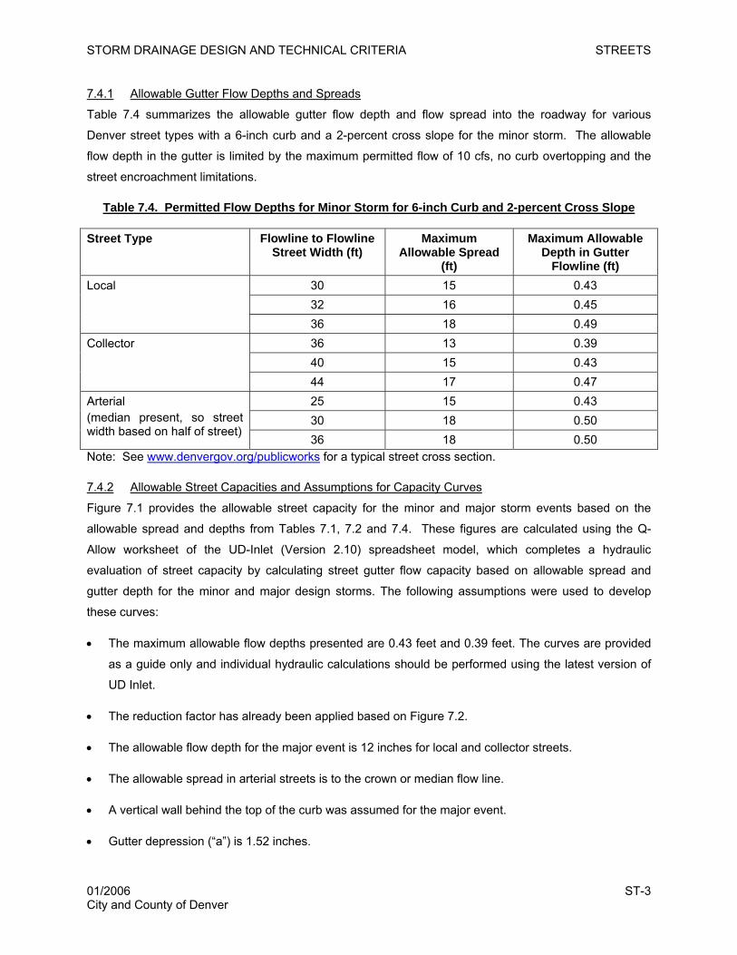
STORM DRAINAGE DESIGN AND TECHNICAL CRITERIA STREETS
7.4.1 Allowable Gutter Flow Depths and Spreads
Table 7.4 summarizes the allowable gutter flow depth and flow spread into the roadway for various
Denver street types with a 6-inch curb and a 2-percent cross slope for the minor storm. The allowable
flow depth in the gutter is limited by the maximum permitted flow of 10 cfs, no curb overtopping and the
street encroachment limitations.
Table 7.4. Permitted Flow Depths for Minor Storm for 6-inch Curb and 2-percent Cross Slope
Street Type Flowline to Flowline Street Width (ft)
Maximum Allowable Spread
(ft)
Maximum Allowable Depth in Gutter
Flowline (ft) 30 15 0.43 32 16 0.45
Local
36 18 0.49 36 13 0.39 40 15 0.43
Collector
44 17 0.47 25 15 0.43 30 18 0.50
Arterial (median present, so street width based on half of street)
36 18 0.50 Note: See www.denvergov.org/publicworks for a typical street cross section.
7.4.2 Allowable Street Capacities and Assumptions for Capacity Curves
Figure 7.1 provides the allowable street capacity for the minor and major storm events based on the
allowable spread and depths from Tables 7.1, 7.2 and 7.4. These figures are calculated using the Q-
Allow worksheet of the UD-Inlet (Version 2.10) spreadsheet model, which completes a hydraulic
evaluation of street capacity by calculating street gutter flow capacity based on allowable spread and
gutter depth for the minor and major design storms. The following assumptions were used to develop
these curves:
• The maximum allowable flow depths presented are 0.43 feet and 0.39 feet. The curves are provided
as a guide only and individual hydraulic calculations should be performed using the latest version of
UD Inlet.
• The reduction factor has already been applied based on Figure 7.2.
• The allowable flow depth for the major event is 12 inches for local and collector streets.
• The allowable spread in arterial streets is to the crown or median flow line.
• A vertical wall behind the top of the curb was assumed for the major event.
• Gutter depression (“a”) is 1.52 inches.
01/2006 ST-3 City and County of Denver
STORM DRAINAGE DESIGN AND TECHNICAL CRITERIA STREETS
• Gutter width is 2 feet.
• Manning’s “n” is 0.016.
• Cross slope is 2 percent.
7.5 Checklist and Design Aids
All of the design criteria in this chapter must be followed. Several key considerations that the designer
must take care to address include:
1. The primary function of urban streets is for safe traffic movement. Where a storm sewer is
available, inlets must be provided at intersections, as shown in Figure 8.3.
2. Provide an inlet where a catch curb changes to a spill curb.
3. Maximum allowable street capacity for minor event is 10 cfs or gutter capacity, whichever is
less.
4. Allowable street capacity for major and minor storms is subject to safety considerations
using the reduction factor taken from Figure 7.2
5. Nuisance flows must be carried by gutters or pans to an inlet. Nuisance flows are not
allowed to cross a driving lane.
6. Cross pans are not allowed on collector or arterial streets or where a storm sewer is
available.
01/2006 ST-4 City and County of Denver
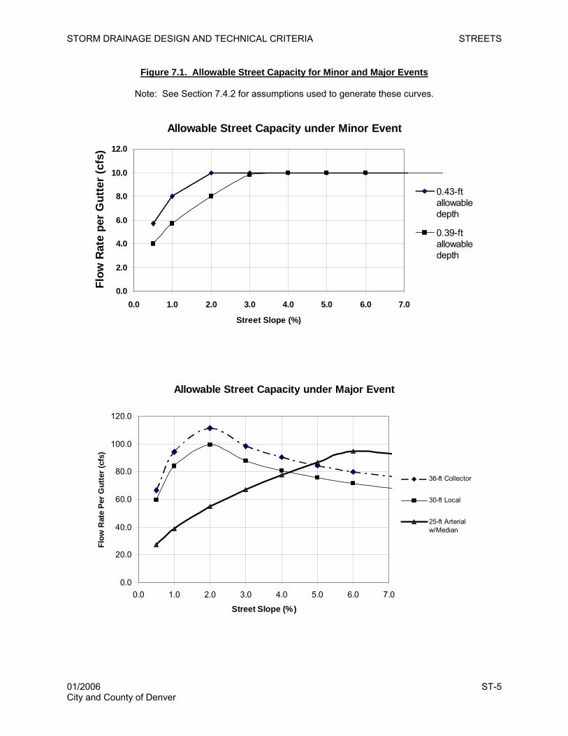
STORM DRAINAGE DESIGN AND TECHNICAL CRITERIA STREETS
Figure 7.1. Allowable Street Capacity for Minor and Major Events
Note: See Section 7.4.2 for assumptions used to generate these curves.
Allowable Street Capacity under Minor Event
0.0
2.0
4.0
6.0
8.0
10.0
12.0
0.0 1.0 2.0 3.0 4.0 5.0 6.0 7.0
Street Slope (%)
Flow
Rat
e pe
r G
utte
r (c
fs)
0.43-ftallowabledepth
0.39-ftallowabledepth
Allowable Street Capacity under Major Event
0.0
20.0
40.0
60.0
80.0
100.0
120.0
0.0 1.0 2.0 3.0 4.0 5.0 6.0 7.0
Street Slope (%)
Flow
Rat
e Pe
r Gut
ter (
cfs)
36-ft Collector
30-ft Local
25-ft Arterialw/Median
01/2006 ST-5 City and County of Denver
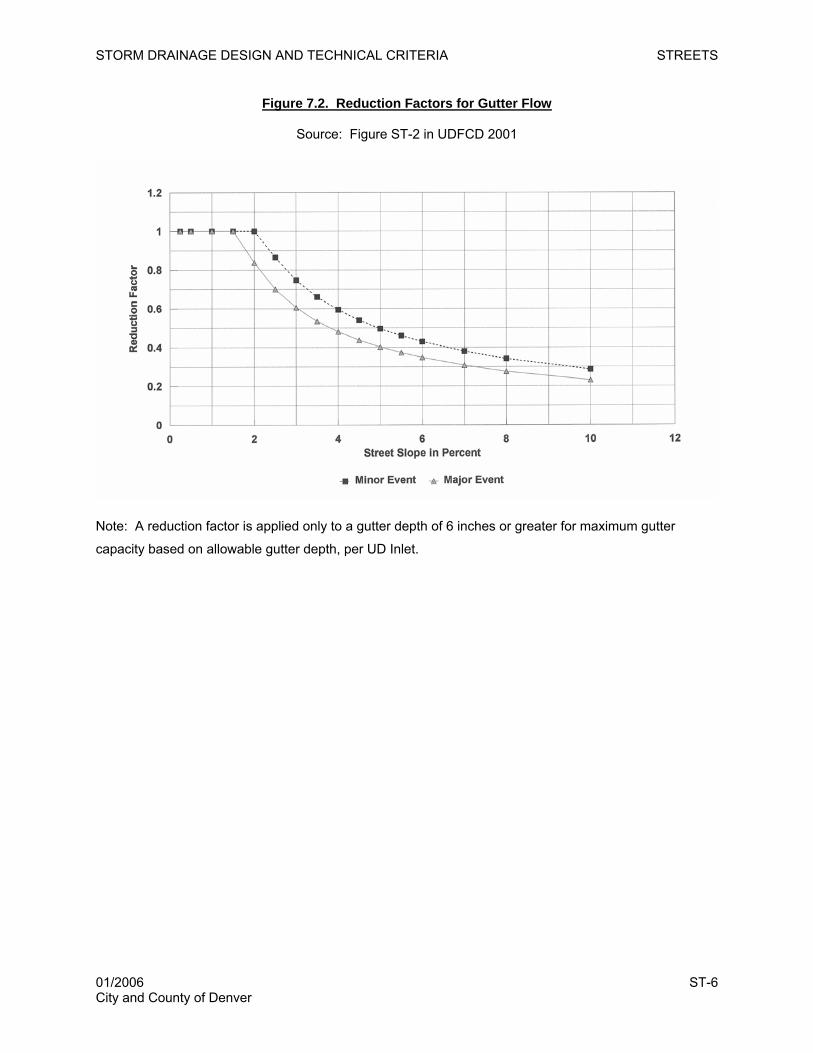
STORM DRAINAGE DESIGN AND TECHNICAL CRITERIA STREETS
Figure 7.2. Reduction Factors for Gutter Flow
Source: Figure ST-2 in UDFCD 2001
Note: A reduction factor is applied only to a gutter depth of 6 inches or greater for maximum gutter
capacity based on allowable gutter depth, per UD Inlet.
01/2006 ST-6 City and County of Denver
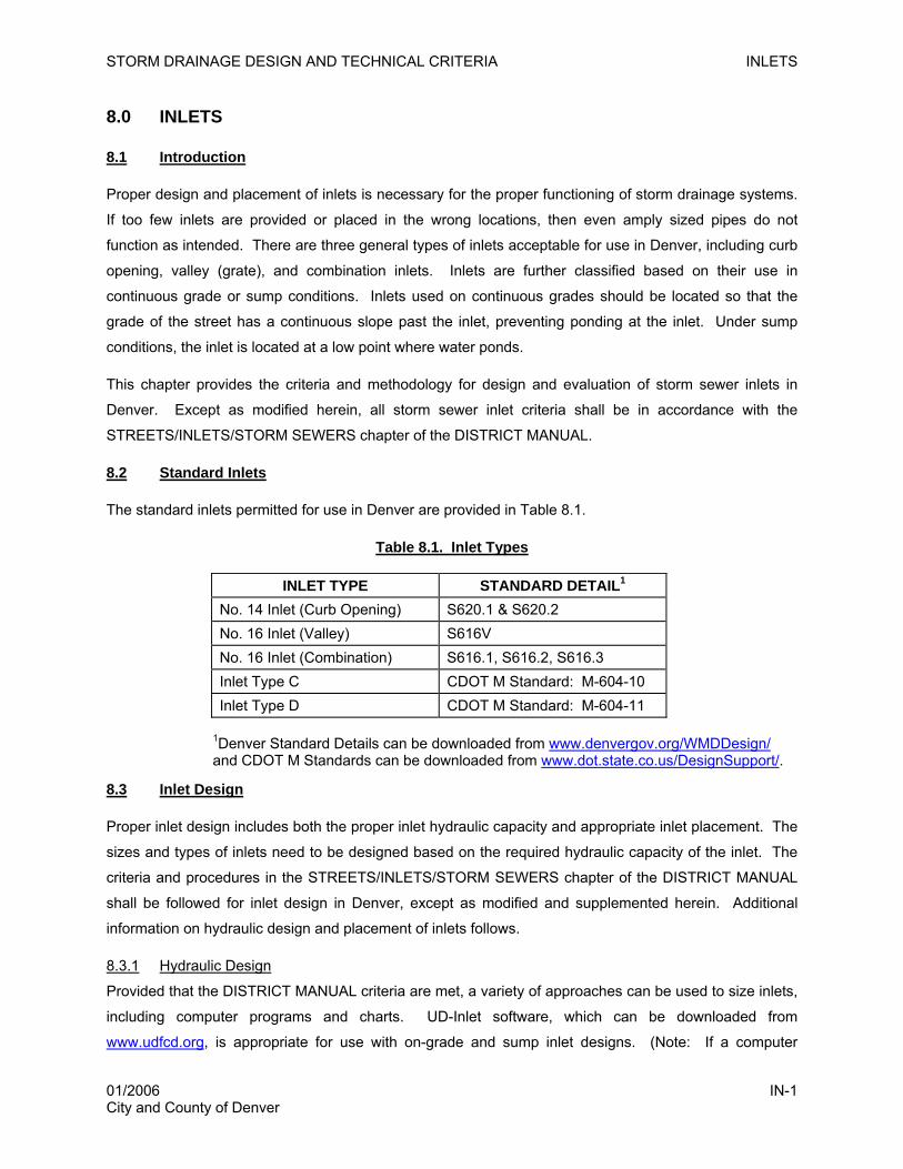
STORM DRAINAGE DESIGN AND TECHNICAL CRITERIA INLETS
8.0 INLETS
8.1 Introduction
Proper design and placement of inlets is necessary for the proper functioning of storm drainage systems.
If too few inlets are provided or placed in the wrong locations, then even amply sized pipes do not
function as intended. There are three general types of inlets acceptable for use in Denver, including curb
opening, valley (grate), and combination inlets. Inlets are further classified based on their use in
continuous grade or sump conditions. Inlets used on continuous grades should be located so that the
grade of the street has a continuous slope past the inlet, preventing ponding at the inlet. Under sump
conditions, the inlet is located at a low point where water ponds.
This chapter provides the criteria and methodology for design and evaluation of storm sewer inlets in
Denver. Except as modified herein, all storm sewer inlet criteria shall be in accordance with the
STREETS/INLETS/STORM SEWERS chapter of the DISTRICT MANUAL.
8.2 Standard Inlets
The standard inlets permitted for use in Denver are provided in Table 8.1.
Table 8.1. Inlet Types
INLET TYPE STANDARD DETAIL1
No. 14 Inlet (Curb Opening) S620.1 & S620.2 No. 16 Inlet (Valley) S616V No. 16 Inlet (Combination) S616.1, S616.2, S616.3 Inlet Type C CDOT M Standard: M-604-10 Inlet Type D CDOT M Standard: M-604-11
1Denver Standard Details can be downloaded from www.denvergov.org/WMDDesign/ and CDOT M Standards can be downloaded from www.dot.state.co.us/DesignSupport/.
8.3 Inlet Design
Proper inlet design includes both the proper inlet hydraulic capacity and appropriate inlet placement. The
sizes and types of inlets need to be designed based on the required hydraulic capacity of the inlet. The
criteria and procedures in the STREETS/INLETS/STORM SEWERS chapter of the DISTRICT MANUAL
shall be followed for inlet design in Denver, except as modified and supplemented herein. Additional
information on hydraulic design and placement of inlets follows.
8.3.1 Hydraulic Design
Provided that the DISTRICT MANUAL criteria are met, a variety of approaches can be used to size inlets,
including computer programs and charts. UD-Inlet software, which can be downloaded from
www.udfcd.org, is appropriate for use with on-grade and sump inlet designs. (Note: If a computer
01/2006 IN-1 City and County of Denver
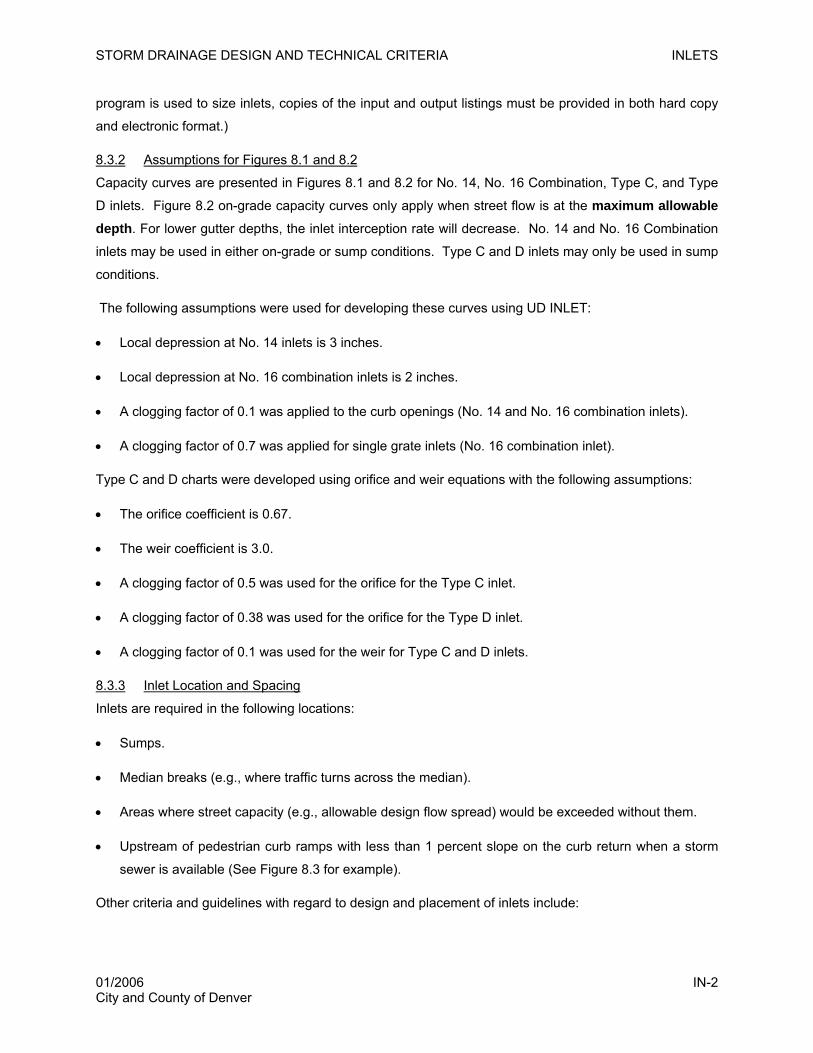
STORM DRAINAGE DESIGN AND TECHNICAL CRITERIA INLETS
program is used to size inlets, copies of the input and output listings must be provided in both hard copy
and electronic format.)
8.3.2 Assumptions for Figures 8.1 and 8.2
Capacity curves are presented in Figures 8.1 and 8.2 for No. 14, No. 16 Combination, Type C, and Type
D inlets. Figure 8.2 on-grade capacity curves only apply when street flow is at the maximum allowable depth. For lower gutter depths, the inlet interception rate will decrease. No. 14 and No. 16 Combination
inlets may be used in either on-grade or sump conditions. Type C and D inlets may only be used in sump
conditions.
The following assumptions were used for developing these curves using UD INLET:
• Local depression at No. 14 inlets is 3 inches.
• Local depression at No. 16 combination inlets is 2 inches.
• A clogging factor of 0.1 was applied to the curb openings (No. 14 and No. 16 combination inlets).
• A clogging factor of 0.7 was applied for single grate inlets (No. 16 combination inlet).
Type C and D charts were developed using orifice and weir equations with the following assumptions:
• The orifice coefficient is 0.67.
• The weir coefficient is 3.0.
• A clogging factor of 0.5 was used for the orifice for the Type C inlet.
• A clogging factor of 0.38 was used for the orifice for the Type D inlet.
• A clogging factor of 0.1 was used for the weir for Type C and D inlets.
8.3.3 Inlet Location and Spacing
Inlets are required in the following locations:
• Sumps.
• Median breaks (e.g., where traffic turns across the median).
• Areas where street capacity (e.g., allowable design flow spread) would be exceeded without them.
• Upstream of pedestrian curb ramps with less than 1 percent slope on the curb return when a storm
sewer is available (See Figure 8.3 for example).
Other criteria and guidelines with regard to design and placement of inlets include:
01/2006 IN-2 City and County of Denver
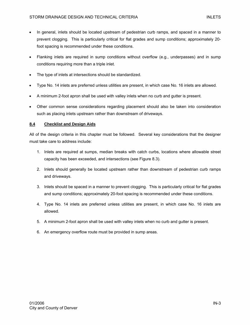
STORM DRAINAGE DESIGN AND TECHNICAL CRITERIA INLETS
• In general, inlets should be located upstream of pedestrian curb ramps, and spaced in a manner to
prevent clogging. This is particularly critical for flat grades and sump conditions; approximately 20-
foot spacing is recommended under these conditions.
• Flanking inlets are required in sump conditions without overflow (e.g., underpasses) and in sump
conditions requiring more than a triple inlet.
• The type of inlets at intersections should be standardized.
• Type No. 14 inlets are preferred unless utilities are present, in which case No. 16 inlets are allowed.
• A minimum 2-foot apron shall be used with valley inlets when no curb and gutter is present.
• Other common sense considerations regarding placement should also be taken into consideration
such as placing inlets upstream rather than downstream of driveways.
8.4 Checklist and Design Aids
All of the design criteria in this chapter must be followed. Several key considerations that the designer
must take care to address include:
1. Inlets are required at sumps, median breaks with catch curbs, locations where allowable street
capacity has been exceeded, and intersections (see Figure 8.3).
2. Inlets should generally be located upstream rather than downstream of pedestrian curb ramps
and driveways.
3. Inlets should be spaced in a manner to prevent clogging. This is particularly critical for flat grades
and sump conditions; approximately 20-foot spacing is recommended under these conditions.
4. Type No. 14 inlets are preferred unless utilities are present, in which case No. 16 inlets are
allowed.
5. A minimum 2-foot apron shall be used with valley inlets when no curb and gutter is present.
6. An emergency overflow route must be provided in sump areas.
01/2006 IN-3 City and County of Denver
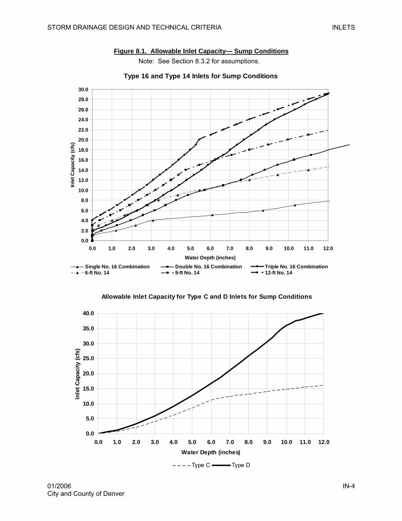
STORM DRAINAGE DESIGN AND TECHNICAL CRITERIA INLETS
Figure 8.1. Allowable Inlet Capacity— Sump Conditions
Type 16 and Type 14 Inlets for Sump Conditions
0.0
2.0
4.0
6.0
8.0
10.0
12.0
14.0
16.0
18.0
20.0
22.0
24.0
26.0
28.0
30.0
0.0 1.0 2.0 3.0 4.0 5.0 6.0 7.0 8.0 9.0 10.0 11.0 12.0
Water Depth (inches)
Inle
t Cap
acity
(cfs
)
Single No. 16 Combination Double No. 16 Combination Triple No. 16 Combination6-ft No. 14 9-ft No. 14 12-ft No. 14
Note: See Section 8.3.2 for assumptions.
Allowable Inlet Capacity for Type C and D Inlets for Sump Conditions
0.0
5.0
10.0
15.0
20.0
25.0
30.0
35.0
40.0
0.0 1.0 2.0 3.0 4.0 5.0 6.0 7.0 8.0 9.0 10.0 11.0 12.0
Water Depth (inches)
Inle
t Cap
acity
(cfs
)
Type C Type D
01/2006 IN-4 City and County of Denver
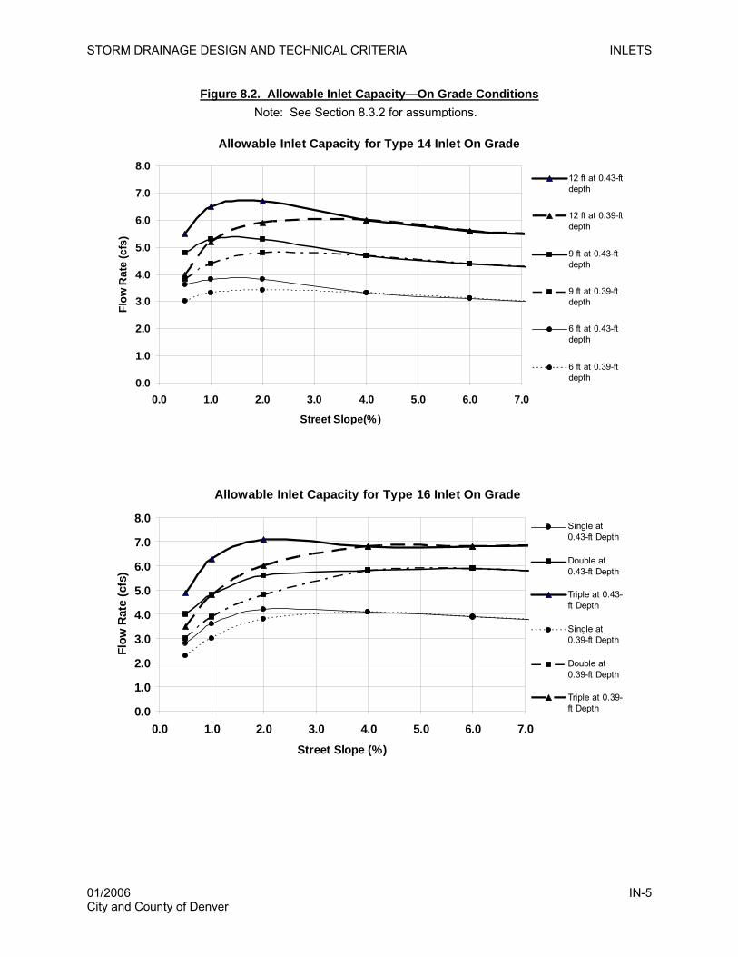
STORM DRAINAGE DESIGN AND TECHNICAL CRITERIA INLETS
Figure 8.2. Allowable Inlet Capacity—On Grade Conditions Note: See Section 8.3.2 for assumptions.
Allowable Inlet Capacity for Type 14 Inlet On Grade
0.0
1.0
2.0
3.0
4.0
5.0
6.0
7.0
8.0
0.0 1.0 2.0 3.0 4.0 5.0 6.0 7.0
Street Slope(%)
Flow
Rat
e (c
fs)
12 ft at 0.43-ftdepth
12 ft at 0.39-ftdepth
9 ft at 0.43-ftdepth
9 ft at 0.39-ftdepth
6 ft at 0.43-ftdepth
6 ft at 0.39-ftdepth
Allowable Inlet Capacity for Type 16 Inlet On Grade
0.0
1.0
2.0
3.0
4.0
5.0
6.0
7.0
8.0
0.0 1.0 2.0 3.0 4.0 5.0 6.0 7.0
Street Slope (%)
Flow
Rat
e (c
fs)
Single at0.43-ft Depth
Double at0.43-ft Depth
Triple at 0.43-ft Depth
Single at0.39-ft Depth
Double at0.39-ft Depth
Triple at 0.39-ft Depth
01/2006 IN-5 City and County of Denver
STORM DRAINAGE DESIGN AND TECHNICAL CRITERIA STORM SEWERS
9.0 STORM SEWERS
9.1 Introduction
Storm sewers are a part of the drainage system and are required when the other parts of the system no
longer have capacity for additional runoff. Except as modified herein, the design of storm sewers shall be
in accordance with the Storm Sewer section of the STREETS/INLETS/STORM SEWERS chapter of the
DISTRICT MANUAL.
9.2 Design Storms for Sizing Storm Sewers
Two design storms shall be considered for sizing storm sewers, the minor (2- or 5-year) storm and the
major (100-year) storm. In each case, storm sewers are to be sized to carry whatever portion of the runoff
that cannot be conveyed on the surface, as dictated by the available capacity in streets and swales during
these two events.
9.2.1 Minor Event Design Storm
At a minimum, storm sewers are to be sized to pick up any minor storm runoff that exceeds the minor
event capacity of the street or roadside swales (discussed in Chapter 7, Streets). Inlets are located at
these points to intercept excess minor event flow and route it to the storm sewer. Storm sewers shall be
designed to convey the minor storm flood peaks while flowing at 80 percent of the full pipe capacity.
Section 9.3 provides additional information on hydraulic design methods for the minor storm.
9.2.2 Major Event Design Storm
There are conditions when the storm sewer system will be sized to convey flows greater than the minor
storm runoff, including locations where:
1) The street capacity for the major storm is exceeded, especially where the grade slopes
down behind the curb and the major storm capacity is limited to the height of the curb.
2) The major storm flows split off in an undesired direction (e.g., flow splits at intersections).
3) The storm sewer system is accepting flow from an upstream storm sewer system or branch
that is designed for the major storm.
4) Regional storm sewers are designed for the major storm.
5) The storm sewers must convey undetained flows to a regional detention basin.
If a storm sewer is to be designed to carry major storm flows, the inlets to the storm sewer shall be
designed accordingly. In pipes designed to convey up to the major storm, the hydraulic grade line (HGL)
is allowed to rise above the top of the storm sewer, but shall be kept at least 1.0 foot below manhole lids,
inlet grates and inlet curb openings. Section 9.3 provides additional information on hydraulic design
methods for the major storm.
01/2006 SS-1 City and County of Denver
STORM DRAINAGE DESIGN AND TECHNICAL CRITERIA STORM SEWERS
9.3 Hydraulic Design
Storm sewers shall be designed to convey the minor storm flood peaks while flowing at 80 percent of the
full pipe capacity. To ensure that this objective is achieved, the hydraulic and energy grade lines shall be
calculated by accounting for pipe friction losses and pipe form losses. Total hydraulic losses shall be
calculated accounting for friction, expansion, contraction, bend, and junction losses following the methods
in the Storm Sewer section of the STREETS/INLETS/STORM SEWERS chapter of the DISTRICT
MANUAL. In addition, for convenience, a chart identifying the hydraulic properties of circular pipe is
provided in Figure 9.1. This chart assumes that the friction coefficient and Manning’s n do not vary
throughout depth. The Neo UD Sewer software program (downloadable from www.udfcd.org) may also
be used to design storm sewers; if used, electronic and hard copy submittals of the program inputs and
outputs are required.
The maximum velocity in all storm sewers shall be 18 ft/sec. The minimum velocity shall be 3 ft/sec at
half-full or full-conduit flow conditions.
The final EGL shall be at or below the proposed ground surface for the design event. The HGL shall not
exceed the crown of the pipe for the minor storm. In cases where the conduit is designed to convey up to
the full 100-year flow, the allowable HGL must be 1 foot below inlet elevations, or 1 foot below ground
where no inlets are present.
9.4 Construction Materials
Construction materials must be in accordance with the most current Denver Storm Drainage and Sanitary
Construction Details and Technical Specifications.
9.5 Pipe Size
The minimum allowable pipe size for storm sewers is dependent upon a practical diameter from the
maintenance standpoint. The length of the sewer also affects maintenance and, therefore, the minimum
diameter. Table 9.1 presents the minimum pipe size for public storm sewers.
01/2006 SS-2 City and County of Denver
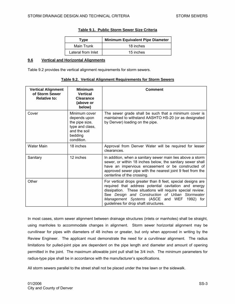
STORM DRAINAGE DESIGN AND TECHNICAL CRITERIA STORM SEWERS
Table 9.1. Public Storm Sewer Size Criteria
Type Minimum Equivalent Pipe Diameter Main Trunk 18 inches
Lateral from Inlet 15 inches
9.6 Vertical and Horizontal Alignments
Table 9.2 provides the vertical alignment requirements for storm sewers.
Table 9.2. Vertical Alignment Requirements for Storm Sewers
Vertical Alignment of Storm Sewer
Relative to:
Minimum Vertical
Clearance (above or
below)
Comment
Cover
Minimum cover depends upon the pipe size, type and class, and the soil bedding condition.
The sewer grade shall be such that a minimum cover is maintained to withstand AASHTO HS-20 (or as designated by Denver) loading on the pipe.
Water Main
18 inches
Approval from Denver Water will be required for lesser clearances.
Sanitary 12 inches In addition, when a sanitary sewer main lies above a storm sewer, or within 18 inches below, the sanitary sewer shall have an impervious encasement or be constructed of approved sewer pipe with the nearest joint 9 feet from the centerline of the crossing.
Other For vertical drops greater than 8 feet, special designs are required that address potential cavitation and energy dissipation. These situations will require special review. See Design and Construction of Urban Stormwater Management Systems (ASCE and WEF 1992) for guidelines for drop shaft structures.
In most cases, storm sewer alignment between drainage structures (inlets or manholes) shall be straight,
using manholes to accommodate changes in alignment. Storm sewer horizontal alignment may be
curvilinear for pipes with diameters of 48 inches or greater, but only when approved in writing by the
Review Engineer. The applicant must demonstrate the need for a curvilinear alignment. The radius
limitations for pulled-joint pipe are dependent on the pipe length and diameter and amount of opening
permitted in the joint. The maximum allowable joint pull shall be 3/4 inch. The minimum parameters for
radius-type pipe shall be in accordance with the manufacturer’s specifications.
All storm sewers parallel to the street shall not be placed under the tree lawn or the sidewalk.
01/2006 SS-3 City and County of Denver
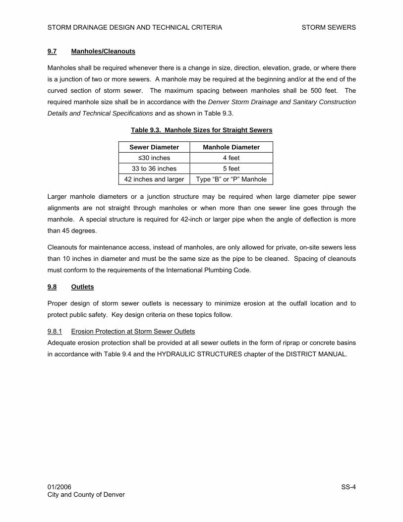
STORM DRAINAGE DESIGN AND TECHNICAL CRITERIA STORM SEWERS
9.7 Manholes/Cleanouts
Manholes shall be required whenever there is a change in size, direction, elevation, grade, or where there
is a junction of two or more sewers. A manhole may be required at the beginning and/or at the end of the
curved section of storm sewer. The maximum spacing between manholes shall be 500 feet. The
required manhole size shall be in accordance with the Denver Storm Drainage and Sanitary Construction
Details and Technical Specifications and as shown in Table 9.3.
Table 9.3. Manhole Sizes for Straight Sewers
Sewer Diameter Manhole Diameter ≤30 inches 4 feet
33 to 36 inches 5 feet 42 inches and larger Type “B” or “P” Manhole
Larger manhole diameters or a junction structure may be required when large diameter pipe sewer
alignments are not straight through manholes or when more than one sewer line goes through the
manhole. A special structure is required for 42-inch or larger pipe when the angle of deflection is more
than 45 degrees.
Cleanouts for maintenance access, instead of manholes, are only allowed for private, on-site sewers less
than 10 inches in diameter and must be the same size as the pipe to be cleaned. Spacing of cleanouts
must conform to the requirements of the International Plumbing Code.
9.8 Outlets
Proper design of storm sewer outlets is necessary to minimize erosion at the outfall location and to
protect public safety. Key design criteria on these topics follow.
9.8.1 Erosion Protection at Storm Sewer Outlets
Adequate erosion protection shall be provided at all sewer outlets in the form of riprap or concrete basins
in accordance with Table 9.4 and the HYDRAULIC STRUCTURES chapter of the DISTRICT MANUAL.
01/2006 SS-4 City and County of Denver

STORM DRAINAGE DESIGN AND TECHNICAL CRITERIA STORM SEWERS
Table 9.4. Erosion Protection at Conduit Outlets
Erosion Protection Type
DISTRICT MANUAL Chapter
Appropriate Use Inappropriate Use
Riprap Lining MAJOR DRAINAGE
Receiving channel on same line and grade
Storm sewer and culvert outlets
High tailwater Fish passage
Wetland channels
Low Tailwater Stilling Basin
HYDRAULIC STRUCTURES
Storm sewer and culvert outlets
Low tailwater
Confined receiving area
Concrete Impact Stilling Basin
HYDRAULIC STRUCTURES
Storm sewer outlets Low tailwater
In-line culvert outlets High visibility areas
Concrete Baffle Chute
HYDRAULIC STRUCTURES
Storm sewer outlets Low tailwater Degrading channel
In-line culvert outlets High debris potential High visibility areas
Drop Structures HYDRAULIC STRUCTURES
Wetland channels Low-rise box culverts or
small diameter pipes where plugging is possible
Confined receiving area Fish passage
Source: Table adapted after Draft Douglas County Drainage Criteria Manual (Muller Engineering 2005).
9.8.2 Safety
Headwalls and wingwalls associated with storm sewer outlets shall be provided with guardrails, handrails,
or fencing in conformance with Denver building codes and roadway design safety requirements.
Handrails shall be required in all areas where the drop from the headwall or wingwall exceeds 30 inches.
The height of the handrail shall be 42 inches for pedestrian walkways or open areas and 54 inches for
bicycle traffic (AASHTO 2002).
9.9 Checklist and Design Aids
All of the design criteria in this chapter must be followed. Several key considerations that the designer
must take care to address include:
1. Design the EGL below the ground surface for the design event.
2. Design the HGL not to exceed the pipe’s crown for the minor storm.
3. Design the HGL not to exceed 1 foot below ground when the conduit is designed to convey
the major event.
01/2006 SS-5 City and County of Denver
STORM DRAINAGE DESIGN AND TECHNICAL CRITERIA STORM SEWERS
4. Account for all losses in the EGL and HGL calculations including outlet, form, bend, manhole,
and junction losses.
5. Provide adequate erosion protection at the outlet of all sewers.
6. Provide cross sections for rip rap protection.
7. Check for minimum pipe cover and clearance with utilities.
8. Check overflow under sump conditions.
9. Design the invert of the inflow pipe to the detention basin to be higher than the water quality
level.
10. Flapgates should only be considered as a last option.
11. Aprons must be provided at outfall structures.
01/2006 SS-6 City and County of Denver
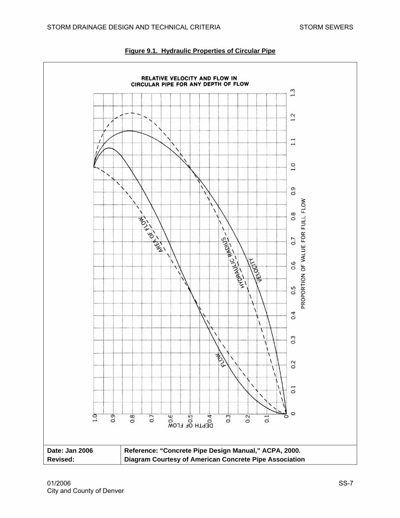
STORM DRAINAGE DESIGN AND TECHNICAL CRITERIA STORM SEWERS
Figure 9.1. Hydraulic Properties of Circular Pipe
Date: Jan 2006 Revised:
Reference: “Concrete Pipe Design Manual,” ACPA, 2000. Diagram Courtesy of American Concrete Pipe Association
01/2006 SS-7 City and County of Denver

STORM DRAINAGE DESIGN AND TECHNICAL CRITERIA STORM SEWERS
This page intentionally left blank.
01/2006 SS-8 City and County of Denver
STORM DRAINAGE DESIGN AND TECHNICAL CRITERIA OPEN CHANNELS
10.0 OPEN CHANNELS
10.1 Introduction
This chapter provides the minimum technical criteria for the hydraulic evaluation and design of open
channels in Denver. In many instances, special design or evaluation techniques will be required. Design
criteria in the Open Channels section of the MAJOR DRAINAGE chapter of the Urban Storm Drainage
Criteria Manual (DISTRICT MANUAL) are hereby incorporated by reference. Except as modified herein,
all open channel designs shall be in accordance with the DISTRICT MANUAL.
10.2 Channel Types
A variety of channel types occur in Denver. These include channels resulting from natural processes and
artificial channels. Examples of natural channels include Bear Creek, the South Platte River, Cherry
Creek and Sand Creek. Most natural channels within the older parts of Denver have been modified in the
past. Artificial channels include large designated floodways, irrigation canals and flumes, roadside
ditches, concrete or rock-lined channels, composite channels, bioengineered channels and grass-lined
channels. An overview of channel types allowed in Denver under various conditions and associated
design considerations is provided below, followed by specific design criteria in Section 10.4 through 10.6.
As previously discussed in Chapter 3, a major drainageway is defined as any drainage flow path with a
tributary area of 130 acres or more. Minor drainageways convey flows from tributary areas less than 130
acres.
10.2.1 Natural Channels
If natural channels are to be used for carrying storm runoff from an urbanized area, the altered nature of
the runoff peaks and volumes from urban development will inevitably cause erosion, which must be
planned for and controlled based on detailed hydraulic analysis. Investigations necessary to assure that
the natural channels will be adequate are different for every waterway. At a minimum, the engineer must
prepare cross sections of the channel, define the water surface profile for the minor and major design
flood, investigate the bed and bank material to determine erosion tendencies, and study the bank slope
stability of the channel under future flow conditions. Supercritical flow does not normally occur in natural
channels, but calculations must be made to assure that the results do not reflect supercritical flow.
Typically, a variety of measures must be implemented to ensure channel stability that may include drop
structures along with both hard (e.g., rip-rap, boulders) and soft (e.g., willows, revegetation, slope
shaping) streambank stabilization measures. The natural floodplain along these channels should be
preserved whenever practicable.
10.2.2 Grass-lined Channels
Denver requires grass-lined channels for major drainageways, except in cases of existing development
where right-of-way (ROW) is restricted. Grass-lined channels provide many benefits such as channel
01/2006 OC-1 City and County of Denver
STORM DRAINAGE DESIGN AND TECHNICAL CRITERIA OPEN CHANNELS
storage, lower velocities, and multiple-use greenbelt benefits. Grass stabilizes the body of the channel,
consolidates the soil mass of the bed, checks the erosion on the channel surface, controls the movement
of soil particles along the channel bottom, and creates turbulence resulting in loss of energy and
increased flow retardance.
Key design considerations for grass-lined channels include erosion, sediment deposition, scour, and
hydraulics. Channels in sandy soils require special erosion control techniques and velocity limitations.
For the purposes of these DENVER CRITERIA, sandy soils are defined as non-cohesive sands classified
as SW, SP, or SM in accordance with the Unified Soil Classification System. The UDFCD publication
Design Guidelines and Criteria for Channels and Hydraulic Structures on Sandy Soil (Simons Li and
Associates 1981) should be used when appropriate. Grass-lined channels in developing areas should be
stabilized with grade control structures to prevent downcutting, depression of the water table and
degradation of natural vegetation. Low-flow areas may need to be armored or otherwise stabilized to
guard against erosion.
10.2.3 Concrete-lined Channels
Concrete-lined channels for major drainageways will be permitted only where ROW restrictions within
existing development prohibit grass-lined channels. The lining must be designed to withstand the various
forces and actions that cause bank overtopping, deteriorate the lining, erode the soil beneath the lining,
and erode unlined areas, especially for the supercritical flow conditions.
If the project constraints suggest the use of a concrete channel for a major drainageway, the applicant
shall present the concept with justification to the Department of Public Works for consideration of a waiver
from these DENVER CRITERIA. If a waiver is granted, supporting design information will be required for
approval of a concrete-lined channel.
10.2.4 Riprap or Rock Lined Channels
Riprap or rock-lined channels are generally discouraged and shall be permitted only in areas of existing
development where ROW for major drainageways is limited and such limitation prohibits the use of grass-
lined channels. The advantage of rock lining a channel is that a steeper channel grade can be used due
to the higher friction of the rock. Also, steeper side slopes are permitted. Rock linings (i.e., revetments)
are permitted as a means of controlling erosion for natural channels. The disadvantages are appearance,
the large initial cost of construction and the high maintenance costs due to vandalism and loss of rock
during high flows.
If the project constraints suggest the use of riprap lining for a major drainageway, then the engineer must
present the concept and its justification to the Review Engineer for consideration of a waiver from these
DENVER CRITERIA.
01/2006 OC-2 City and County of Denver
STORM DRAINAGE DESIGN AND TECHNICAL CRITERIA OPEN CHANNELS
10.2.5 Other Channel Types
The MAJOR DRAINAGE chapter of the DISTRICT MANUAL provides criteria for composite channels,
which have a distinct low-flow channel vegetated with a mixture of wetland and riparian vegetation, and
bioengineered channels, which use vegetative components and other natural materials in combination
with structural measures to construct natural-like channels. These channel types are allowed in Denver
when designed in accordance with the DISTRICT MANUAL criteria.
Additionally, a variety of commercially available synthetic fabrics and channel lining products intended to
reduce erosion are available. The use of synthetic fabrics for lining of channels for major drainageways
within Denver is restricted to areas of existing development where the ROW constraints prohibit the use
of a grass-lined section and where existing drainage problems are evident. The linings shall be restricted
to channels with a Froude number of 0.8 or less. Such use shall be allowed only upon written approval
for a waiver from the Review Engineer.
The DISTRICT MANUAL also provides guidance for boatable channels, where special safety
considerations must be considered for drop structures and other channel characteristics.
10.3 Flow Computations and Design Approach
Regardless of the type of channel selected, hydraulic analyses must be conducted to evaluate flow
characteristics, including flow regime, water surface elevations, velocities, depths and hydraulic
transitions for multiple flow conditions. All flow computations shall be in accordance with the MAJOR
DRAINAGE chapter of the DISTRICT MANUAL. The UD-Channels spreadsheet (downloadable from
www.udfcd.org) may be used to complete some flow calculations; however, water surface profile
calculations necessary to determine the energy grade line (EGL), water surface elevation, and hydraulic
grade line (HGL) must be completed separately using the methods in the DISTRICT MANUAL. All
channels shall be designed considering public safety and maintenance requirements.
If published UDFCD or Denver outfall system or drainage master plans exist, then channel designs
should be completed in accordance with the recommendations of these plans.
10.4 Design Criteria for Natural Channels
The design criteria and evaluation techniques for natural channels are:
1. Channel and overbank areas shall have adequate capacity for the 100-year storm runoff.
2. Erosion-control structures, such as drop structures or grade-control checks, shall be provided to
control channel erosion as the tributary watershed urbanizes.
3. Water surface profiles shall be defined so that the floodplain can be zoned and protected.
01/2006 OC-3 City and County of Denver
STORM DRAINAGE DESIGN AND TECHNICAL CRITERIA OPEN CHANNELS
4. Filling of the floodplain shall be avoided because it reduces valuable channel storage capacity and
tends to increase downstream runoff peaks.
5. Roughness factors (n values) representative of unmaintained channel conditions shall be used for the
analysis of water surface profiles.
6. Roughness factors (n values) representative of maintained channel conditions shall be used to
determine velocity limitations.
7. Control structures will typically be required to decrease the thalweg slope, control erosion and
sediment deposition for both the major and the minor storm runoff. The appearance of these
structures should be compatible with their surroundings. Where possible, structures should be
located at principal grade changes to minimize the cost of retaining structures, reduce perceived
scale and appearance of mass and bulk, and use existing land forms of the site. All check drops,
dams, or structures should, whenever feasible, use natural materials to integrate with natural
landscape characteristics and should only be provided where necessary as indicated by hydraulic
analyses.
8. Plan and profile drawings of the floodplain shall be prepared. Appropriate allowances for known
future bridges or culverts, which can raise the water surface profile and cause the floodplain to be
extended, shall be included in the analysis. The applicant shall contact the Public Works Department
for information on future bridges and roads in undeveloped areas.
9. Natural waterway channel boundaries and alignments shall be preserved, maintained or enhanced in
their natural condition to serve as landscape and visual amenities, to provide focal points for
development projects, and to help define “edges” in and around communities. Vegetation groups,
rock outcroppings, terrain form, soils, waterways, and bodies of water shall be preserved to the extent
practicable.
10. The usual rules of freeboard depth, curvature and other factors, which are applicable to artificial
channels, do not apply for natural channels. A minimum of 1 foot of freeboard above the 100-year
water surface shall be provided, with 3 feet provided at bridges and 18 inches at structures.
Significant benefits may be realized if channel overtopping and localized flooding of adjacent areas
are planned for the major runoff peak.
11. If a natural channel is to be used as a major drainageway for a development, then the applicant shall
meet with the Department of Public Works to discuss the concept and obtain the requirements for
planning and design documentation. Approval of the concept and design will be made in accordance
with the requirements of Chapter 2 of these DENVER CRITERIA.
01/2006 OC-4 City and County of Denver
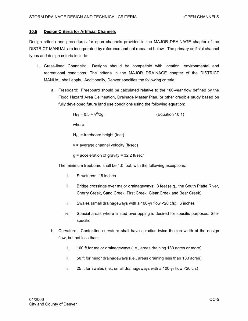
STORM DRAINAGE DESIGN AND TECHNICAL CRITERIA OPEN CHANNELS
10.5 Design Criteria for Artificial Channels
Design criteria and procedures for open channels provided in the MAJOR DRAINAGE chapter of the
DISTRICT MANUAL are incorporated by reference and not repeated below. The primary artificial channel
types and design criteria include:
1. Grass-lined Channels: Designs should be compatible with location, environmental and
recreational conditions. The criteria in the MAJOR DRAINAGE chapter of the DISTRICT
MANUAL shall apply. Additionally, Denver specifies the following criteria:
a. Freeboard: Freeboard should be calculated relative to the 100-year flow defined by the
Flood Hazard Area Delineation, Drainage Master Plan, or other credible study based on
fully developed future land use conditions using the following equation:
HFB = 0.5 + v2/2g (Equation 10.1)
where
HFB = freeboard height (feet)
v = average channel velocity (ft/sec)
g = acceleration of gravity = 32.2 ft/sec2
The minimum freeboard shall be 1.0 foot, with the following exceptions:
i. Structures: 18 inches
ii. Bridge crossings over major drainageways: 3 feet (e.g., the South Platte River,
Cherry Creek, Sand Creek, First Creek, Clear Creek and Bear Creek)
iii. Swales (small drainageways with a 100-yr flow <20 cfs): 6 inches
iv. Special areas where limited overtopping is desired for specific purposes: Site-
specific
b. Curvature: Center-line curvature shall have a radius twice the top width of the design
flow, but not less than:
i. 100 ft for major drainageways (i.e., areas draining 130 acres or more)
ii. 50 ft for minor drainageways (i.e., areas draining less than 130 acres)
iii. 25 ft for swales (i.e., small drainageways with a 100-yr flow <20 cfs)
01/2006 OC-5 City and County of Denver
STORM DRAINAGE DESIGN AND TECHNICAL CRITERIA OPEN CHANNELS
c. Roughness Coefficient: Use the maximum Manning’s n value for determining the
channel hydraulic capacity and the minimum value for determining the channel lining
stability.
d. Main Channel: A main channel is required for sandy soils, but may also be used with
other soil conditions.
e. Trickle Channel: Baseflows shall be carried in a concrete trickle channel that provides a
minimum capacity of 2 percent of the 100-year flow, but not less than 1 cfs. Alternatives
to concrete will be considered on a case-by-case basis. Composite or wetland-bottom-
type channels are allowed and must be designed in accordance with the DISTRICT
MANUAL. For swales, trickle channel requirements will be evaluated on a case-by-case
basis.
f. Bottom Width: The minimum bottom width shall be consistent with the maximum depth
and velocity criteria and shall not be less than 4 feet or the trickle channel width when
trickle channel is required.
g. Water Surface Profiles: The energy gradient shall be shown on all drawings. The
standard method for determining the water surface profile is the U.S. Army Corps of
Engineers HEC-RAS computer model.
h. Other Hydraulic Information: For minor drainageways, submit capacity and velocity
calculations and Froude numbers with construction drawings, including electronic
submittal of spreadsheets.
2. Riprap-lined Channels: The criteria in the MAJOR DRAINAGE chapter of the DISTRICT
MANUAL shall apply.
3. Concrete-lined, Composite and Bioengineered Channels: The criteria in the MAJOR DRAINAGE
chapter of the DISTRICT MANUAL shall apply.
4. Manufactured Lining Types: The criteria in the MAJOR DRAINAGE chapter of the DISTRICT
MANUAL shall apply, as well as the manufacturer’s recommendations for the specific product.
The applicant will be required to submit the technical data in support of the proposed material.
Additional information or calculations may be requested by the Department of Public Works to
verify assumptions or design criteria.
Regardless of the channel type, vegetation and land form, variations are encouraged to enhance the
aesthetic quality of channels, provided that channel functional factors are not compromised. Channel
capacity must be increased to accommodate increases in plant material types and densities and variation
of land form. Overstory canopy trees are allowed and encouraged outside of high hazard areas.
01/2006 OC-6 City and County of Denver
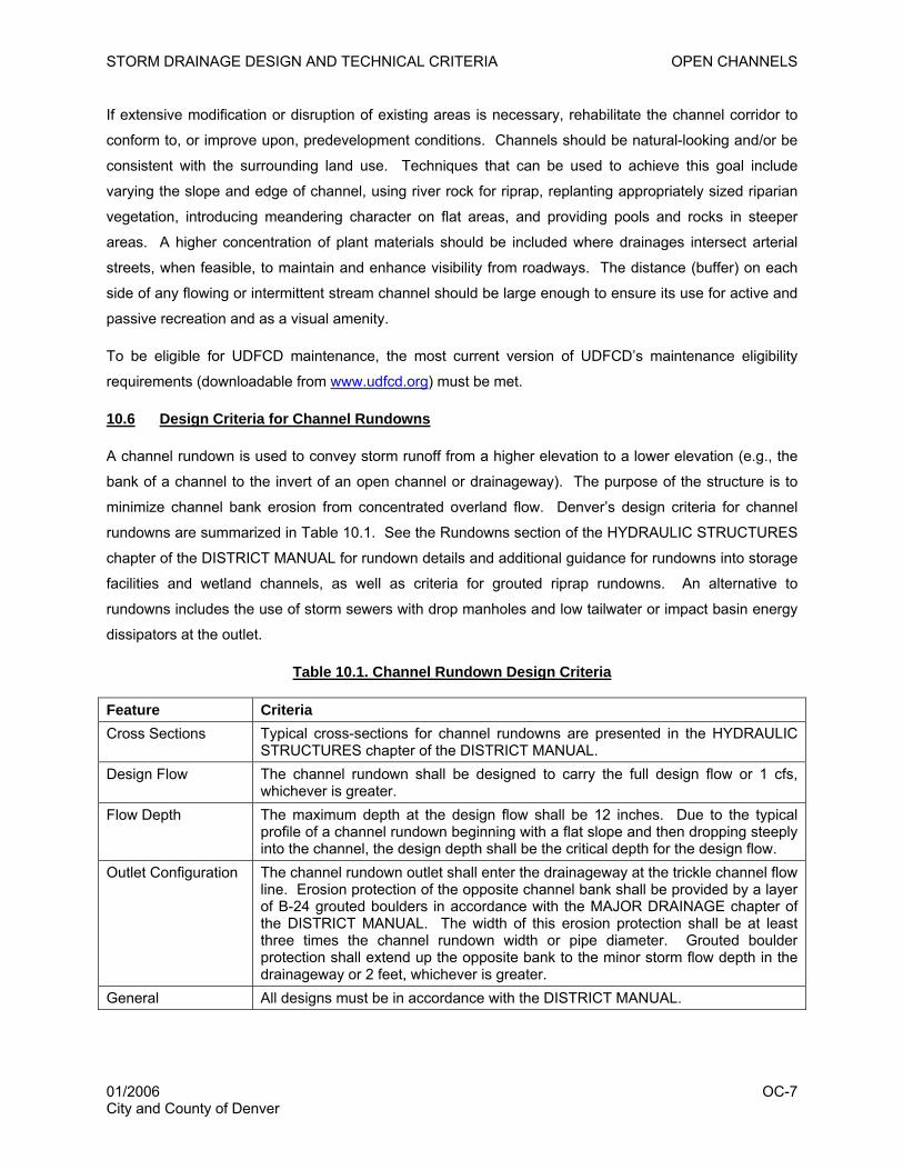
STORM DRAINAGE DESIGN AND TECHNICAL CRITERIA OPEN CHANNELS
If extensive modification or disruption of existing areas is necessary, rehabilitate the channel corridor to
conform to, or improve upon, predevelopment conditions. Channels should be natural-looking and/or be
consistent with the surrounding land use. Techniques that can be used to achieve this goal include
varying the slope and edge of channel, using river rock for riprap, replanting appropriately sized riparian
vegetation, introducing meandering character on flat areas, and providing pools and rocks in steeper
areas. A higher concentration of plant materials should be included where drainages intersect arterial
streets, when feasible, to maintain and enhance visibility from roadways. The distance (buffer) on each
side of any flowing or intermittent stream channel should be large enough to ensure its use for active and
passive recreation and as a visual amenity.
To be eligible for UDFCD maintenance, the most current version of UDFCD’s maintenance eligibility
requirements (downloadable from www.udfcd.org) must be met.
10.6 Design Criteria for Channel Rundowns
A channel rundown is used to convey storm runoff from a higher elevation to a lower elevation (e.g., the
bank of a channel to the invert of an open channel or drainageway). The purpose of the structure is to
minimize channel bank erosion from concentrated overland flow. Denver’s design criteria for channel
rundowns are summarized in Table 10.1. See the Rundowns section of the HYDRAULIC STRUCTURES
chapter of the DISTRICT MANUAL for rundown details and additional guidance for rundowns into storage
facilities and wetland channels, as well as criteria for grouted riprap rundowns. An alternative to
rundowns includes the use of storm sewers with drop manholes and low tailwater or impact basin energy
dissipators at the outlet.
Table 10.1. Channel Rundown Design Criteria
Feature Criteria Cross Sections Typical cross-sections for channel rundowns are presented in the HYDRAULIC
STRUCTURES chapter of the DISTRICT MANUAL. Design Flow The channel rundown shall be designed to carry the full design flow or 1 cfs,
whichever is greater. Flow Depth The maximum depth at the design flow shall be 12 inches. Due to the typical
profile of a channel rundown beginning with a flat slope and then dropping steeply into the channel, the design depth shall be the critical depth for the design flow.
Outlet Configuration The channel rundown outlet shall enter the drainageway at the trickle channel flow line. Erosion protection of the opposite channel bank shall be provided by a layer of B-24 grouted boulders in accordance with the MAJOR DRAINAGE chapter of the DISTRICT MANUAL. The width of this erosion protection shall be at least three times the channel rundown width or pipe diameter. Grouted boulder protection shall extend up the opposite bank to the minor storm flow depth in the drainageway or 2 feet, whichever is greater.
General All designs must be in accordance with the DISTRICT MANUAL.
01/2006 OC-7 City and County of Denver
STORM DRAINAGE DESIGN AND TECHNICAL CRITERIA OPEN CHANNELS
10.7 Retrofitting Existing Channels
Many redevelopment projects in Denver provide opportunities for retrofitting and improving existing open
channels. Guidance for retrofitting existing channels is provided in the MAJOR DRAINAGE chapter of the
DISTRICT MANUAL.
10.8 Environmental Permitting
A variety of federal (e.g., 404 permit), state (e.g., dewatering, stormwater) and local permits are often
required when constructing open channels. The engineer shall obtain necessary permits.
10.9 Checklist and Design Aids
All of the design criteria in this chapter must be followed. Several key considerations that the designer
must take care to address include:
1. Check flow velocity with low retardance (“n”) factor and capacity with high retardance factor.
2. Check Froude number and critical flow conditions.
3. Grass channel side slopes must be 4:1 or flatter.
4. Show EGL and water surface profile on design drawings.
5. Consider all backwater conditions (i.e., at culverts) when determining channel capacity.
6. Check velocity for conditions without backwater effects.
7. Provide adequate freeboard.
8. Provide adequate ROW for the channel and continuous maintenance access.
01/2006 OC-8 City and County of Denver
STORM DRAINAGE DESIGN AND TECHNICAL CRITERIA HYDRAULIC STRUCTURES
11.0 HYDRAULIC STRUCTURES
11.1 Introduction
Hydraulic structures are used to guide and control water flow velocities, directions and depths, elevation
and slope of streambed, general configuration of the waterway, and its stability and maintenance
characteristics. Hydraulic structures (e.g., riprap, channel grade control structures, bridges) help to
control the energy associated with flowing water, thereby reducing erosion-related damage to the stream.
Consideration of environmental, ecological, aesthetic and public safety objectives should be integrated
with careful and thorough hydraulic engineering design. The proper application of hydraulic structures
can reduce initial and future maintenance costs by managing the character of the flow to fit the
environmental and project needs. All hydraulic structures should be designed and constructed
considering aesthetics and should fit in with their surroundings to the extent practicable. Structures must
be designed with long-term maintainability as a key criterion.
The criteria to be used in the design of hydraulic structures shall be in accordance with the HYDRAULIC
STRUCTURES and MAJOR DRAINAGE chapters of the DISTRICT MANUAL, unless modified herein.
11.2 Application of Hydraulic Structures and Design Guidance
Table 11.1 summarizes the types of hydraulic structures that may be constructed in Denver and cross-
references the reader to the appropriate criteria and guidance for their construction. A checklist for
hydraulic structure design is also provided in the HYDRAULIC STRUCTURES chapter of the DISTRICT
MANUAL.
01/2006 HS-1 City and County of Denver
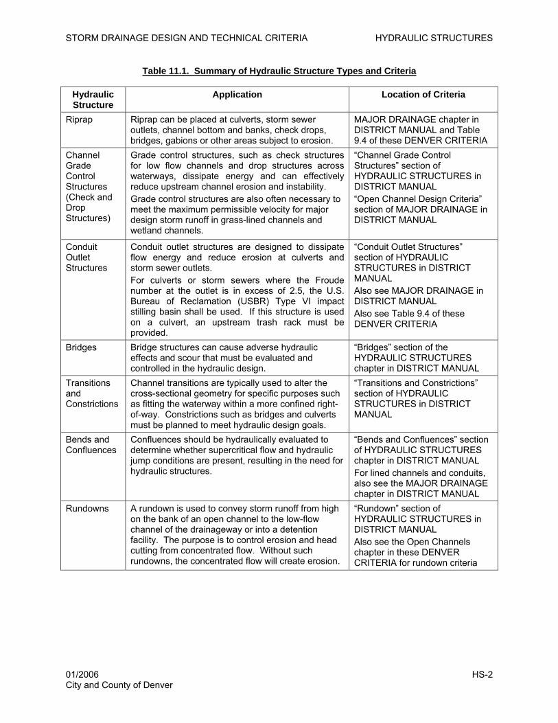
STORM DRAINAGE DESIGN AND TECHNICAL CRITERIA HYDRAULIC STRUCTURES
Table 11.1. Summary of Hydraulic Structure Types and Criteria
Hydraulic Structure
Application Location of Criteria
Riprap Riprap can be placed at culverts, storm sewer outlets, channel bottom and banks, check drops, bridges, gabions or other areas subject to erosion.
MAJOR DRAINAGE chapter in DISTRICT MANUAL and Table 9.4 of these DENVER CRITERIA
Channel Grade Control Structures (Check and Drop Structures)
Grade control structures, such as check structures for low flow channels and drop structures across waterways, dissipate energy and can effectively reduce upstream channel erosion and instability. Grade control structures are also often necessary to meet the maximum permissible velocity for major design storm runoff in grass-lined channels and wetland channels.
“Channel Grade Control Structures” section of HYDRAULIC STRUCTURES in DISTRICT MANUAL “Open Channel Design Criteria” section of MAJOR DRAINAGE in DISTRICT MANUAL
Conduit Outlet Structures
Conduit outlet structures are designed to dissipate flow energy and reduce erosion at culverts and storm sewer outlets. For culverts or storm sewers where the Froude number at the outlet is in excess of 2.5, the U.S. Bureau of Reclamation (USBR) Type VI impact stilling basin shall be used. If this structure is used on a culvert, an upstream trash rack must be provided.
“Conduit Outlet Structures” section of HYDRAULIC STRUCTURES in DISTRICT MANUAL Also see MAJOR DRAINAGE in DISTRICT MANUAL Also see Table 9.4 of these DENVER CRITERIA
Bridges Bridge structures can cause adverse hydraulic effects and scour that must be evaluated and controlled in the hydraulic design.
“Bridges” section of the HYDRAULIC STRUCTURES chapter in DISTRICT MANUAL
Transitions and Constrictions
Channel transitions are typically used to alter the cross-sectional geometry for specific purposes such as fitting the waterway within a more confined right-of-way. Constrictions such as bridges and culverts must be planned to meet hydraulic design goals.
“Transitions and Constrictions” section of HYDRAULIC STRUCTURES in DISTRICT MANUAL
Bends and Confluences
Confluences should be hydraulically evaluated to determine whether supercritical flow and hydraulic jump conditions are present, resulting in the need for hydraulic structures.
“Bends and Confluences” section of HYDRAULIC STRUCTURES chapter in DISTRICT MANUAL For lined channels and conduits, also see the MAJOR DRAINAGE chapter in DISTRICT MANUAL
Rundowns A rundown is used to convey storm runoff from high on the bank of an open channel to the low-flow channel of the drainageway or into a detention facility. The purpose is to control erosion and head cutting from concentrated flow. Without such rundowns, the concentrated flow will create erosion.
“Rundown” section of HYDRAULIC STRUCTURES in DISTRICT MANUAL Also see the Open Channels chapter in these DENVER CRITERIA for rundown criteria
01/2006 HS-2 City and County of Denver
STORM DRAINAGE DESIGN AND TECHNICAL CRITERIA CULVERTS
12.0 CULVERTS
12.1 Introduction
A culvert is defined as a conduit for the conveyance of water under a roadway, railroad, canal, or other
embankment. In addition to serving hydraulic functions, culverts also must carry overhead loads from
traffic and other activities, thereby serving a structural function. Proper culvert design is essential
because culverts often significantly influence upstream and downstream flood risks, floodplain
management and public safety. The criteria presented in this chapter shall be used in the design of
culverts. The criteria, techniques, and design examples provided in the CULVERTS chapter of the
DISTRICT MANUAL are hereby incorporated by reference and not repeated herein, unless modified by
Denver.
12.2 General Design and Hydraulic Evaluation
The hydraulic principles, criteria, roughness coefficients, entrance loss coefficients, culvert capacity charts
and other information provided in the CULVERTS chapter of the DISTRICT MANUAL shall be used in the
hydraulic evaluation, sizing and design of culverts, except as modified herein. The UD-Culvert
spreadsheet (downloadable from www.udfcd.org) may also be used in the hydraulic evaluation of
culverts. When used, the software input and output listings should be submitted to Denver in electronic
and hard copy formats.
Additional references prepared by the Colorado Department of Transportation and the Federal Highway
Administration (e.g., FHWA 1985, Ginsberg 1987) may also be helpful in hydraulic evaluation of culverts,
particularly with regard to bridge crossings.
12.3 Culvert Sizing Criteria
For street crossings, the minimum culvert size is based on the allowable street overtopping for the various
street classifications as set forth in Table 12.1 and allowable headwater depths as discussed in Section
12.7. In no case shall street overtopping occur for a 10-year frequency or smaller storm. Other
conditions may be present that will require a larger culvert size, particularly with regard to public safety
concerns and upstream and downstream impacts. In some cases, the minimum criteria may result in
some structures remaining in the 100-year floodplain, which may require an increase in culvert size to
lower the floodplain elevation. Also, if only a small increase in culvert size is required to prevent
overtopping, then the larger culvert is required.
01/2006 CUL-1 City and County of Denver
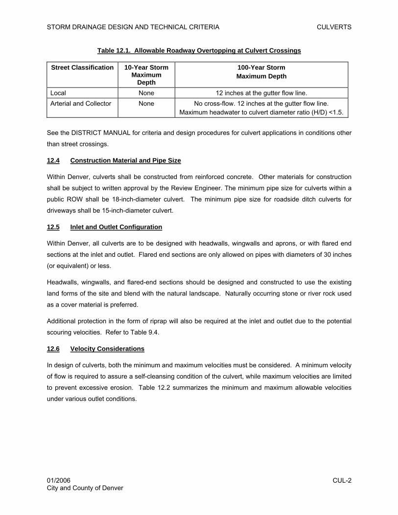
STORM DRAINAGE DESIGN AND TECHNICAL CRITERIA CULVERTS
Table 12.1. Allowable Roadway Overtopping at Culvert Crossings
Street Classification 10-Year Storm Maximum
Depth
100-Year Storm Maximum Depth
Local None 12 inches at the gutter flow line. Arterial and Collector None No cross-flow. 12 inches at the gutter flow line.
Maximum headwater to culvert diameter ratio (H/D) <1.5.
See the DISTRICT MANUAL for criteria and design procedures for culvert applications in conditions other
than street crossings.
12.4 Construction Material and Pipe Size
Within Denver, culverts shall be constructed from reinforced concrete. Other materials for construction
shall be subject to written approval by the Review Engineer. The minimum pipe size for culverts within a
public ROW shall be 18-inch-diameter culvert. The minimum pipe size for roadside ditch culverts for
driveways shall be 15-inch-diameter culvert.
12.5 Inlet and Outlet Configuration
Within Denver, all culverts are to be designed with headwalls, wingwalls and aprons, or with flared end
sections at the inlet and outlet. Flared end sections are only allowed on pipes with diameters of 30 inches
(or equivalent) or less.
Headwalls, wingwalls, and flared-end sections should be designed and constructed to use the existing
land forms of the site and blend with the natural landscape. Naturally occurring stone or river rock used
as a cover material is preferred.
Additional protection in the form of riprap will also be required at the inlet and outlet due to the potential
scouring velocities. Refer to Table 9.4.
12.6 Velocity Considerations
In design of culverts, both the minimum and maximum velocities must be considered. A minimum velocity
of flow is required to assure a self-cleansing condition of the culvert, while maximum velocities are limited
to prevent excessive erosion. Table 12.2 summarizes the minimum and maximum allowable velocities
under various outlet conditions.
01/2006 CUL-2 City and County of Denver
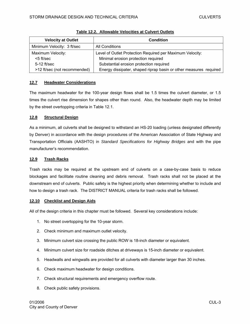
STORM DRAINAGE DESIGN AND TECHNICAL CRITERIA CULVERTS
Table 12.2. Allowable Velocities at Culvert Outlets
Velocity at Outlet Condition Minimum Velocity: 3 ft/sec All Conditions Maximum Velocity: <5 ft/sec 5-12 ft/sec >12 ft/sec (not recommended)
Level of Outlet Protection Required per Maximum Velocity: Minimal erosion protection required Substantial erosion protection required Energy dissipater, shaped riprap basin or other measures required
12.7 Headwater Considerations
The maximum headwater for the 100-year design flows shall be 1.5 times the culvert diameter, or 1.5
times the culvert rise dimension for shapes other than round. Also, the headwater depth may be limited
by the street overtopping criteria in Table 12.1.
12.8 Structural Design
As a minimum, all culverts shall be designed to withstand an HS-20 loading (unless designated differently
by Denver) in accordance with the design procedures of the American Association of State Highway and
Transportation Officials (AASHTO) in Standard Specifications for Highway Bridges and with the pipe
manufacturer’s recommendation.
12.9 Trash Racks
Trash racks may be required at the upstream end of culverts on a case-by-case basis to reduce
blockages and facilitate routine cleaning and debris removal. Trash racks shall not be placed at the
downstream end of culverts. Public safety is the highest priority when determining whether to include and
how to design a trash rack. The DISTRICT MANUAL criteria for trash racks shall be followed.
12.10 Checklist and Design Aids
All of the design criteria in this chapter must be followed. Several key considerations include:
1. No street overtopping for the 10-year storm.
2. Check minimum and maximum outlet velocity.
3. Minimum culvert size crossing the public ROW is 18-inch diameter or equivalent.
4. Minimum culvert size for roadside ditches at driveways is 15-inch diameter or equivalent.
5. Headwalls and wingwalls are provided for all culverts with diameter larger than 30 inches.
6. Check maximum headwater for design conditions.
7. Check structural requirements and emergency overflow route.
8. Check public safety provisions.
01/2006 CUL-3 City and County of Denver
STORM DRAINAGE DESIGN AND TECHNICAL CRITERIA CULVERTS
This page intentionally left blank.
01/2006 CUL-4 City and County of Denver
STORM DRAINAGE DESIGN AND TECHNICAL CRITERIA DETENTION (STORAGE)
01/2006 DET-1 City and County of Denver
13.0 DETENTION (STORAGE)
13.1 Introduction
Detention of flood flows for all development and redevelopment projects (as defined in Section 1.3) is
required in accordance with the policies presented in Section 3.3.1.12 of these DENVER CRITERIA. The
main purpose of a detention facility is to store the excess storm runoff associated with increased basin
imperviousness and discharge this excess at a rate similar to the rate experienced from the basin without
development.
This chapter provides the criteria that shall be used in the design and evaluation of all detention facilities.
The criteria presented in the STORAGE chapter of the DISTRICT MANUAL are hereby incorporated by
reference and shall be adhered to unless elaborated upon or modified herein. Any special design
conditions that cannot be defined by these DENVER CRITERIA shall be reviewed by the Department of
Public Works before proceeding with design. Denver strongly encourages integration of detention and
water quality treatment requirements in accordance with the strategies presented in Chapter 6 of the
current Denver Water Quality Management Plan, which can be downloaded from
http://www.denvergov.org/publicworks/ and Volume 3 of the DISTRICT MANUAL. All detention facilities
must have adequate maintenance access and be maintained on a regular basis.
13.2 Design Criteria
13.2.1 Design Storm Event Frequency
All detention facilities shall be designed to control the 10- and 100-year recurrence interval floods and
may be combined with the water quality capture volume (WQCV).
13.2.2 Sizing Methodology for Volumes and Release Rates
Table 13.1 summarizes acceptable methodologies for sizing detention facilities. The STORAGE chapter
of the DISTRICT MANUAL should be referenced for application of these methods. Input and output
listings used with software programs shall be provided to Denver in electronic and hard copy formats.
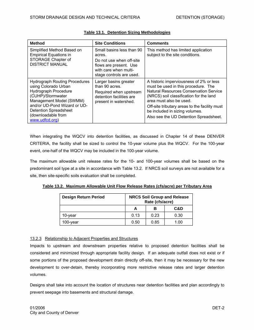
STORM DRAINAGE DESIGN AND TECHNICAL CRITERIA DETENTION (STORAGE)
Table 13.1. Detention Sizing Methodologies
Method Site Conditions Comments Simplified Method Based on Empirical Equations in STORAGE Chapter of DISTRICT MANUAL
Small basins less than 90 acres. Do not use when off-site flows are present. Use with care when multi-stage controls are used.
This method has limited application subject to the site conditions.
Hydrograph Routing Procedures using Colorado Urban Hydrograph Procedure (CUHP)/Stormwater Management Model (SWMM) and/or UD-Pond Wizard or UD-Detention Spreadsheet (downloadable from www.udfcd.org)
Larger basins greater than 90 acres. Required when upstream detention facilities are present in watershed.
A historic imperviousness of 2% or less must be used in this procedure. The Natural Resources Conservation Service (NRCS) soil classification for the land area must also be used. Off-site tributary areas to the facility must be included in sizing volumes. Also see the UD Detention Spreadsheet.
When integrating the WQCV into detention facilities, as discussed in Chapter 14 of these DENVER
CRITERIA, the facility shall be sized to control the 10-year volume plus the WQCV. For the 100-year
event, one-half of the WQCV may be included in the 100-year volume.
The maximum allowable unit release rates for the 10- and 100-year volumes shall be based on the
predominant soil type at a site in accordance with Table 13.2. If NRCS soil surveys are not available for a
site, then site-specific soils evaluation shall be completed.
Table 13.2. Maximum Allowable Unit Flow Release Rates (cfs/acre) per Tributary Area
Design Return Period NRCS Soil Group and Release Rate (cfs/acre)
A B C&D 10-year 0.13 0.23 0.30 100-year 0.50 0.85 1.00
13.2.3 Relationship to Adjacent Properties and Structures
Impacts to upstream and downstream properties relative to proposed detention facilities shall be
considered and minimized through appropriate facility design. If an adequate outfall does not exist or if
some portions of the proposed development drain directly off-site, then it may be necessary for the new
development to over-detain, thereby incorporating more restrictive release rates and larger detention
volumes.
Designs shall take into account the location of structures near detention facilities and plan accordingly to
prevent seepage into basements and structural damage.
01/2006 DET-2 City and County of Denver
STORM DRAINAGE DESIGN AND TECHNICAL CRITERIA DETENTION (STORAGE)
13.2.4 Maintenance
All detention facilities shall be designed with adequate maintenance access provisions and in a manner
that facilitates ease of maintenance. For larger regional facilities to be eligible for UDFCD maintenance,
the most current version of UDFCD’s maintenance eligibility requirements (downloadable from
www.udfcd.org) must be met.
13.3 Detention Methods
There are two basic approaches to designing storage facilities. When runoff storage facilities are planned
on an individual site basis, they are referred to as “on-site.” Larger facilities that have been identified and
sized as a part of some overall regional plan are categorized as “regional” facilities. In addition, the
regional definition can also be applied to storage facilities that address moderately sized watersheds to
encompass multiple land development projects. This chapter focuses primarily on on-site detention
facilities. In order for Denver to consider regional facilities, the following criteria must be met:
1. A Denver-approved master plan recommends the regional detention facility.
2. The regional detention facility is designed to accommodate the fully developed flows from
the upstream watershed.
3. The regional detention facility is constructed, or will be constructed in phases with the
development; otherwise, temporary detention must be provided.
4. Legally-binding ownership and maintenance responsibilities by a public entity are clearly
defined to ensure the proper function of the facility in perpetuity.
5. There is adequate conveyance of the fully developed flows from the site to the regional
detention basin.
6. Design is completed in accordance with the DISTRICT MANUAL, considering these criteria:
a. Multi-use (e.g., recreation) shall be considered in the design of detention basins.
b. The creation of jurisdictional dams shall be strongly discouraged.
c. Basins shall be located on existing publicly-owned lands whenever possible.
d. If regional flood control detention facilities incorporate regional extended detention
basins for stormwater quality, developments upstream of the regional facility shall
provide the minimum level of onsite stormwater quality enhancement identified in
Chapter 14, Stormwater Quality.
Criteria for several approaches to on-site detention are provided in the remainder of this chapter based on
the facility being located in open space, parking lots or underground. Underground detention is only
01/2006 DET-3 City and County of Denver
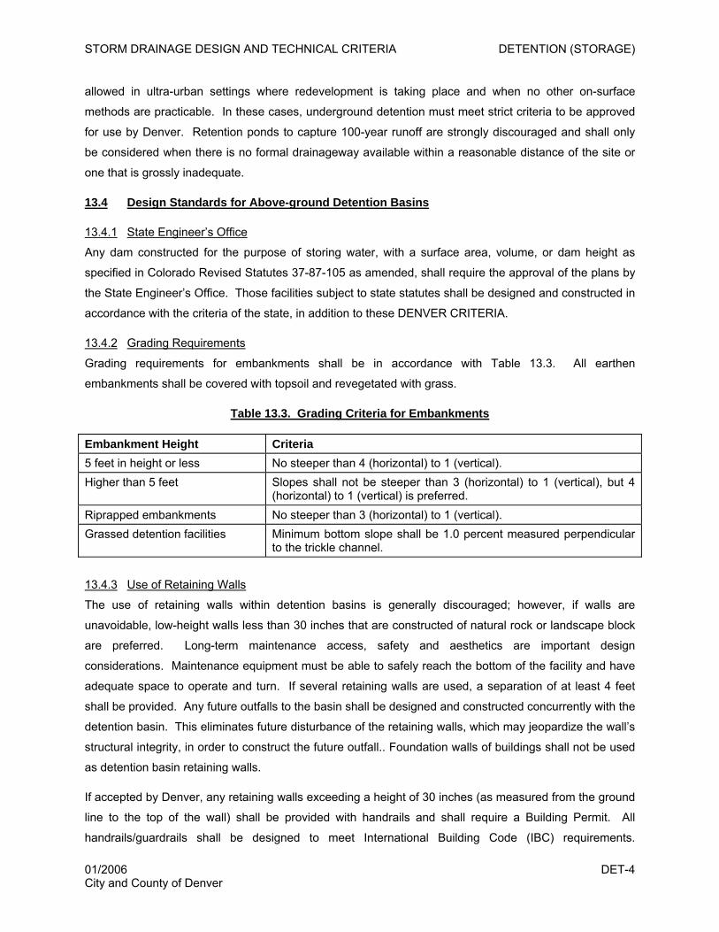
STORM DRAINAGE DESIGN AND TECHNICAL CRITERIA DETENTION (STORAGE)
allowed in ultra-urban settings where redevelopment is taking place and when no other on-surface
methods are practicable. In these cases, underground detention must meet strict criteria to be approved
for use by Denver. Retention ponds to capture 100-year runoff are strongly discouraged and shall only
be considered when there is no formal drainageway available within a reasonable distance of the site or
one that is grossly inadequate.
13.4 Design Standards for Above-ground Detention Basins
13.4.1 State Engineer’s Office
Any dam constructed for the purpose of storing water, with a surface area, volume, or dam height as
specified in Colorado Revised Statutes 37-87-105 as amended, shall require the approval of the plans by
the State Engineer’s Office. Those facilities subject to state statutes shall be designed and constructed in
accordance with the criteria of the state, in addition to these DENVER CRITERIA.
13.4.2 Grading Requirements
Grading requirements for embankments shall be in accordance with Table 13.3. All earthen
embankments shall be covered with topsoil and revegetated with grass.
Table 13.3. Grading Criteria for Embankments
Embankment Height Criteria 5 feet in height or less No steeper than 4 (horizontal) to 1 (vertical). Higher than 5 feet Slopes shall not be steeper than 3 (horizontal) to 1 (vertical), but 4
(horizontal) to 1 (vertical) is preferred. Riprapped embankments No steeper than 3 (horizontal) to 1 (vertical). Grassed detention facilities Minimum bottom slope shall be 1.0 percent measured perpendicular
to the trickle channel.
13.4.3 Use of Retaining Walls
The use of retaining walls within detention basins is generally discouraged; however, if walls are
unavoidable, low-height walls less than 30 inches that are constructed of natural rock or landscape block
are preferred. Long-term maintenance access, safety and aesthetics are important design
considerations. Maintenance equipment must be able to safely reach the bottom of the facility and have
adequate space to operate and turn. If several retaining walls are used, a separation of at least 4 feet
shall be provided. Any future outfalls to the basin shall be designed and constructed concurrently with the
detention basin. This eliminates future disturbance of the retaining walls, which may jeopardize the wall’s
structural integrity, in order to construct the future outfall.. Foundation walls of buildings shall not be used
as detention basin retaining walls.
If accepted by Denver, any retaining walls exceeding a height of 30 inches (as measured from the ground
line to the top of the wall) shall be provided with handrails and shall require a Building Permit. All
handrails/guardrails shall be designed to meet International Building Code (IBC) requirements.
01/2006 DET-4 City and County of Denver
STORM DRAINAGE DESIGN AND TECHNICAL CRITERIA DETENTION (STORAGE)
Appropriate measures (typically an all-weather access road to the basin bottom) shall be included to allow
for access by maintenance equipment.
Walled-in or steep-sided basins should be located away from major pedestrian routes and emergency
egress routes should be provided. Site lighting may also be required to discourage illicit activity in walled-
in basins.
A licensed professional engineer shall perform a structural analysis of the retaining wall for the various
loading conditions the wall may encounter. The wall design and calculations shall be stamped by the
professional engineer and submitted to Denver for review. The structural design details and requirements
for the retaining wall(s) shall be included in the construction drawings.
13.4.4 Freeboard Requirements
For sites greater than or equal to 5 acres, the elevation of the top of the embankment shall be a minimum
of 1 foot above the water surface elevation when the emergency spillway is conveying the maximum
design or emergency flow. For sites less than 5 acres, the minimum required freeboard is 1.0 foot above
the computed 100-year water surface elevation in the detention facility.
13.4.5 Inlet Configuration
Inlets shall be designed in accordance with the DISTRICT MANUAL. Forebays shall be provided, as
shown in Figure 13.1, to reduce sediment loading to the facility. Such forebays shall be regularly
maintained.
13.4.6 Trickle Channel (Low Flow) Control
All grassed bottom detention basins shall include a concrete trickle channel designed according to
DISTRICT MANUAL and as illustrated in Figure 13.2.
13.4.7 Outlet Configuration
The DISTRICT MANUAL and UDFCD website (www.udfcd.org) provide design guidance, design details
and examples for several detention basin outlet configurations. Figure 13.3 provides design details with
Denver’s criteria incorporated. The minimum allowable size of the outlet pipe is 8 inches, provided that it
can convey 120 percent of the 100-year outflow, and a control orifice plate at the entrance of the pipe is
required to control the discharge of the design flow. The trash rack must be designed in accordance with
the DISTRICT MANUAL. Clogging is a particularly important concern on small sites. Figure 13.4
illustrates how outlet designs and trash racks may be used to minimize clogging. The UDFCD website
(www.udfcd.org) should be referenced for design details illustrating the integration of the WQCV into
detention facilities.
All outlets shall be designed to minimize unauthorized modifications that affect proper function. A sign
with a minimum area of 1.0 square foot shall be attached to the outlet or posted nearby (if unable to be
posted to the outlet) with the following message:
01/2006 DET-5 City and County of Denver
STORM DRAINAGE DESIGN AND TECHNICAL CRITERIA DETENTION (STORAGE)
WARNING Keep screen and grate clean.
Unauthorized modification of this outlet is a code violation.
13.4.8 Embankment Protection/Emergency Spillway Requirements
Whenever a detention basin uses an embankment to contain water, the embankment shall be protected
from catastrophic failure due to overtopping. Overtopping can occur when the basin outlets become
obstructed or when a larger than 100-year storm occurs. The emergency spillway of a storage facility
should be designed to pass flows in excess of the design flow of the outlet works. When the storage
facility falls under the jurisdiction of the Colorado State Engineer’s Office (SEO), the spillway’s design
storm is prescribed by the SEO (SEO 1988). If the storage facility is not a jurisdictional structure, the size
of the spillway design storm should be based upon the risk and consequences of a facility failure.
Generally, embankments should have spillways that, at a minimum, are capable of conveying the total
peak 100-year storm discharge from a fully developed total tributary catchment, including all off-site
areas, if any. Frequently, however, analysis of downstream hazards will indicate that the spillway design
storm will need to be larger than the 100-year event.
Failure protection for the embankment may be provided in the form of a buried heavy soil riprap layer on
the entire downstream face of the embankment or a separate emergency spillway. Structures shall not
be located in the path of the emergency spillway or overflow. The invert of the emergency spillway
should be set equal to or above the 100-year water surface elevation.
13.4.9 Landscaping Requirements
Water diversion/detention areas and embankments should be designed and constructed to blend with
their surroundings, creating site amenities rather than eyesores. The Denver Water Quality Management
Plan should be referenced for more guidance on designing aesthetically pleasing facilities. In open space
or natural areas, techniques to be considered include creation of topographic changes that mimic natural
conditions (including a variety of slope changes), using natural materials such as stone, blending with the
textures and patterns of the surrounding landscape, and using materials that match the local
environment. Existing drainage patterns should be preserved whenever possible.
All above-ground detention basins shall be revegetated in accordance with the criteria described in the
REVEGETATION Chapter of the DISTRICT MANUAL. Additionally, landscaping improvements may be
provided in the basin to enhance the aesthetics of the basin. When determining landscaping, long-term
maintainability of the facility should be a high priority. The following is a list of guidelines (adapted from
Draft Douglas County Storm Drainage Criteria Manual, Muller Engineering, 2005) for basin landscaping:
• Detention areas should have attractive natural-looking features, fit into the surrounding landscape
and add to the overall character of an area, as opposed to having boxy and geometric features. The
shape of the detention basin should be as natural looking as practical, with terracing of the slopes
01/2006 DET-6 City and County of Denver
STORM DRAINAGE DESIGN AND TECHNICAL CRITERIA DETENTION (STORAGE)
and bottom. The tops and the toes of slopes should vary, and there should be an undulation in the
shape and grading of the sides of the detention area.
• Slopes should vary and be well vegetated to prevent erosion. The use of appropriate groundcovers
and grasses at the top of the slope help to soften the appearance of the detention area and can
incorporate the detention area into the landscape design. Appropriate plant material, such as wetland
species or drought tolerant species, should be planted in the detention area and on the slopes.
Shrubs and trees should be planted back from the top of the slope. Native and perennial species
should be used to the extent practical.
• Use of rock or wood mulch in and adjacent to detention facilities is discouraged because of its
potential to be displaced and clog outlet structures. Mulch placed over filter fabric is particularly
susceptible to displacement and should not be used on slopes greater than 6 (horizontal) to 1
(vertical) or below the 100-year water surface elevation.
• Rundowns, which convey runoff from streets and parking lots into channels or storage facilities,
should be incorporated into the overall design and be attractively designed.
13.4.10 Multiple Use Considerations
Multiple uses of detention facilities are encouraged; however, it is critical that the uses of these areas be
taken into account to ensure that usage conflicts are minimized. For example, areas used as soccer
fields or golf courses need to drain within a reasonable timeframe to prevent soggy fields that are
incompatible with recreational use. Other park and detention facility conflicts may relate to safety in areas
used for child play, West Nile virus concerns, and/or protection and enhancement of wildlife. Specific
factors that shall be considered for multiple use facilities include:
• Compatibility with design, historic designation or other protective constraints including wildlife habitat
and protection.
• Compatibility with recreational uses. The level of organized and informal activity in a park must be
considered.
• Technical constraints and opportunities including soil characteristics, turf management, or terrain.
• Potential for new natural areas and wildlife corridors.
• Size and configuration of the park. For example, a small neighborhood park under five acres would
probably not be appropriate for a detention facility.
• Maintenance and operations, funding resources, successful techniques for dealing with silt, debris,
etc.
• The configuration and easements for underground utilities and their impact on the existing park land.
01/2006 DET-7 City and County of Denver
STORM DRAINAGE DESIGN AND TECHNICAL CRITERIA DETENTION (STORAGE)
• Potential for total rehabilitation of existing sites to accommodate multi-purpose uses.
• Impacts on all aspects of the open space system: Highline Canal and trails, South Platte River
Greenway, natural areas including potential areas such as along gulches, traditional parks, and other
publicly owned lands.
13.5 Design Standards for Parking Lot Detention
13.5.1 Depth Limitation
The maximum allowable design depth of ponding in parking lots for the 100-year flood is 12 inches.
13.5.2 Outlet Configuration
Where a drop inlet is used to discharge to a storm sewer or drainageway, the minimum pipe size for the
outlet is 8-inch diameter, provided that it can convey 120 percent of the 100-year outflow. Where a weir
and a small diameter outlet through a curb are used, the size and shape are dependent on the
discharge/storage requirements. A minimum 4-inch-diameter pipe size is recommended. See Figure
13.5 for a representative outlet structure for use with small structures in parking lots.
13.5.3 Performance
To assure that the detention facility performs as designed, maintenance access shall be provided in
accordance with Section 3.3.3. The outlet shall be designed to minimize unauthorized modifications,
which affect function. Any repaving of the parking lot shall be evaluated for impact on volume and
release rates and is subject to approval by the Department of Public Works. A sign shall be attached or
posted in accordance with Section 13.5.4.
13.5.4 Flood Hazard Warning
All parking lot detention areas shall have multiple signs posted identifying the detention basin area. The
signs shall have a minimum area of 1.5 square feet and containing the following message:
WARNING This area is a detention basin and is subject
to periodic flooding to a depth of (provide design depth).
Any suitable materials and geometry of the sign are permissible, subject to approval by the Department of
Public Works.
13.6 Design Standards for Underground Detention
Underground detention is strongly discouraged in Denver for the following reasons:
• Underground detention is not visible; therefore, it tends to be “out-of-sight, out-of-mind.” As a result,
these devices do not typically receive regular maintenance, nor is their performance periodically
monitored.
01/2006 DET-8 City and County of Denver
STORM DRAINAGE DESIGN AND TECHNICAL CRITERIA DETENTION (STORAGE)
• Maintenance access is often poor, which can be a deterrent to maintenance.
• Anaerobic (absence of dissolved oxygen) conditions in bottom sediments are more likely to develop
in underground devices. This condition can release pollutants that were bound to the sediment and
cause bad odors.
Nevertheless, Denver recognizes that there are some cases where the use of such facilities is necessary
due to extreme space constraints in smaller, ultra-urban redevelopment sites. Denver will consider the
use of underground detention under these circumstances; however, the applicant must comply with the
following restrictions prior to receiving authorization for its use:
• Clear evidence must be provided documenting why detention cannot be provided on the ground
surface and why the use of an underground facility is the best choice for the site, considering factors
such as initial installation, maintenance, and ability to assure long-term function.
• The WQCV must still be provided above-ground, even if detention is provided below ground.
When no other alternative is practicable, the requirements for underground detention are provided below.
13.6.1 Materials
Underground detention shall be constructed using corrugated aluminum pipe (CAP), reinforced concrete
pipe (RCP), concrete vaults or approved equivalents. Galvanized or aluminumized pipes are not
acceptable. The pipe thickness, cover, bedding, and backfill shall be designed to withstand HS-20
loading, or as otherwise required by Denver.
13.6.2 Configuration
Pipe or vault segments shall be sufficient in number, height, and length to provide the required minimum
storage volume. The minimum headroom height of the pipe or vault segments shall be 48 inches to
permit maintenance.
If parallel pipes are used, the pipe segments shall be placed side by side and connected at both ends by
elbow and tee fittings (see Figure 13.6). The pipe segments shall be continuously sloped at a minimum
of 0.25 percent to the outlet. Manholes for maintenance access shall be placed in the tee fittings, bends
and in the straight segments of the pipe, when required.
Permanent buildings or structures shall not be placed directly above the underground detention.
13.6.3 Inlet and Outlet Design
Inlets to detention facilities can be surface inlets, pipes and/or a local private storm sewer system.
Outlets from underground detention shall consist of a short (maximum 50 foot) length(s) of pipe with an 8-
inch minimum diameter that can convey 120 percent of the 100-year outflow. A two-pipe outlet may be
required to control both design return periods. The invert of the lowest outlet pipe shall be set at the
01/2006 DET-9 City and County of Denver
STORM DRAINAGE DESIGN AND TECHNICAL CRITERIA DETENTION (STORAGE)
lowest point in the detention vault. The outlet pipe(s) shall discharge into a standard manhole or standard
inlet or into an open drainageway with erosion protection. If an orifice plate is required to control the
release rates, the plate(s) shall have a hinge on one side to open into the detention pipes to facilitate
back flushing of the outlet pipe(s) and be firmly bolted or secured to the wall to prevent leakage around
the edges.
13.6.4 Maintenance Access
Access easements to the detention facility shall be provided in accordance with Figure 13.6.
Maintenance access designs shall take into consideration Occupational Safety and Health Administration
(OSHA) requirements for confined space entry.
13.7 Design Standards for 100-year Runoff Retention Ponds
13.7.1 Allowable Use
A retention facility (a pond with a zero release rate or a very slow release rate when a trickle outflow can
be tolerated) is used when there is no available formal downstream drainageway, or one that is grossly
inadequate. When designing a retention facility, the hydrologic basis of design is difficult to describe
because of the stochastic nature of rainfall events. Thus, sizing for a given set of assumptions does not
ensure that another scenario produced by nature (e.g., a series of small storms that add up to large
volumes over a week or two) will not overwhelm the intended design. For this reason, retention ponds
are strongly discouraged as a permanent solution for drainage problems. They have been used in some
instances as temporary measures until a formal system is developed downstream.
When a retention pond is proposed as a temporary solution to an evolving drainage problem, the pond
shall be sized to capture, as a minimum, the runoff equal to 1.5 times the 24-hour, 100-year storm plus 1-
foot freeboard. The facility also shall be situated and designed so that when it overtops, no human-
occupied or critical structures (e.g., electrical vaults) will be flooded, and no catastrophic failure at the
facility (e.g., loss of dam embankment) will occur. Retention facilities shall be as shallow as feasible to
encourage infiltration and other losses of the captured urban runoff. A minimum infiltration drawdown of
the volume in 72 hours will be required for all retention ponds. If this volume cannot be infiltrated within
this time frame, a secondary outlet must be designed to provide additional releases from the pond.
13.7.2 Calculation of Retention Volume
The standard methodology described below in Equation 13.1 and Table 13.4 shall be used for calculating
the required volume for retention. The intent of this methodology is to provide a simple, reasonable
calculation without compromising Denver’s policies for public safety and welfare.
01/2006 DET-10 City and County of Denver
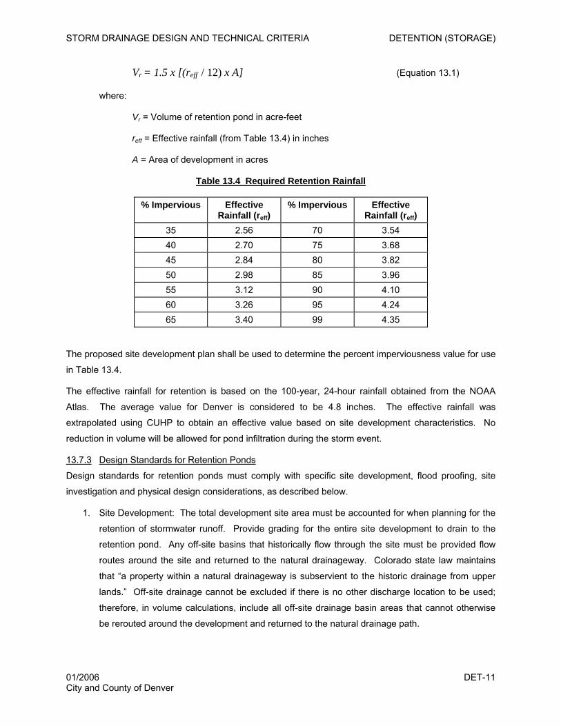
STORM DRAINAGE DESIGN AND TECHNICAL CRITERIA DETENTION (STORAGE)
Vr = 1.5 x [(reff / 12) x A] (Equation 13.1)
where:
Vr = Volume of retention pond in acre-feet
reff = Effective rainfall (from Table 13.4) in inches
A = Area of development in acres
Table 13.4 Required Retention Rainfall
% Impervious Effective Rainfall (reff)
% Impervious Effective Rainfall (reff)
35 2.56 70 3.54 40 2.70 75 3.68 45 2.84 80 3.82 50 2.98 85 3.96 55 3.12 90 4.10 60 3.26 95 4.24 65 3.40 99 4.35
The proposed site development plan shall be used to determine the percent imperviousness value for use
in Table 13.4.
The effective rainfall for retention is based on the 100-year, 24-hour rainfall obtained from the NOAA
Atlas. The average value for Denver is considered to be 4.8 inches. The effective rainfall was
extrapolated using CUHP to obtain an effective value based on site development characteristics. No
reduction in volume will be allowed for pond infiltration during the storm event.
13.7.3 Design Standards for Retention Ponds
Design standards for retention ponds must comply with specific site development, flood proofing, site
investigation and physical design considerations, as described below.
1. Site Development: The total development site area must be accounted for when planning for the
retention of stormwater runoff. Provide grading for the entire site development to drain to the
retention pond. Any off-site basins that historically flow through the site must be provided flow
routes around the site and returned to the natural drainageway. Colorado state law maintains
that “a property within a natural drainageway is subservient to the historic drainage from upper
lands.” Off-site drainage cannot be excluded if there is no other discharge location to be used;
therefore, in volume calculations, include all off-site drainage basin areas that cannot otherwise
be rerouted around the development and returned to the natural drainage path.
01/2006 DET-11 City and County of Denver

STORM DRAINAGE DESIGN AND TECHNICAL CRITERIA DETENTION (STORAGE)
2. Floodproofing: The construction of a retention pond is essentially creating an isolated floodplain
on the property. Delineate the limits of the 100-year flood area on the design drawing. Provide 1
foot of freeboard from the 100-year maximum water surface elevation of retention pond volume.
Provide a 100-year emergency release overflow route from the site, which returns the flow back
to its natural drainage path. Ensure finished floor elevations are 1.5 feet above the water surface
elevation when the emergency spillway is conveying the maximum design flow or emergency
flow.
3. Site Investigation: Site selection for infiltration retention ponds is critical. Factors for evaluating
site suitability include:
• Location of groundwater table
• Location of bedrock
• Seasonal fluctuation of water table
• Soil permeability and porosity
• Soil profile
• Environmental conditions (e.g., contaminated soils)
• Proximity to structures (e.g., basements)
The following factors would preclude the site’s use as a retention infiltration pond:
• A seasonal high groundwater of less than 4 feet below the pond bottom
• Bedrock within 4 feet of the pond bottom
• Pond location over fill
• Surface and underlying soils classified as NRCS Hydrologic Group D
• Saturated infiltration rate less than 0.3 inch per hour
A thorough geotechnical and geohydrological investigation shall be performed to determine site
suitability. The following shall be included in the investigation:
• Soil borings to a depth of 10 feet or to bedrock
• Percolation tests
• Soil classification
4. Physical Design Characteristics: The pond construction shall conform to the criteria as explained
in Section 13.4 for above-ground detention basins. Section 13.4.2 shall be adhered to for grading
01/2006 DET-12 City and County of Denver
STORM DRAINAGE DESIGN AND TECHNICAL CRITERIA DETENTION (STORAGE)
requirements. Section 13.4.8 shall be consulted for embankment protection as required. Section
13.4.9 shall be referred to for landscaping requirements.
13.8 Checklist and Design Aids
All of the design criteria in this chapter must be followed. Several key considerations that the designer
must take care to address include:
1) Grade earth slopes 4:1 or flatter.
2) Provide minimum freeboard of 1 foot.
3) Provide trickle channels in above-ground detention areas.
4) Protect embankment from overtopping conditions.
5) Provide proper trash racks at all outlet structures.
6) Provide signs as required.
7) Provide maintenance access.
8) Provide emergency spillway and check emergency overflow path.
9) Check finished floor elevation of any structure near the detention basin.
10) Ensure that failure of underground detention is clearly evident from above ground.
11) Design the invert of the inflow pipe to the detention basin to be higher than the water quality
level.
01/2006 DET-13 City and County of Denver
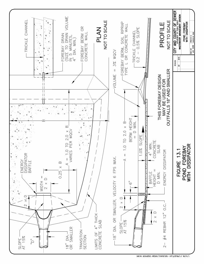
MAY
BE
US
ED F
OR
OU
TFA
LLS
18" A
ND
SM
ALLE
RP
RO
FILE
NO
T TO
SC
ALE
THIS
FO
RE
BA
Y D
ES
IGN
PLA
NN
OT
TO S
CA
LE

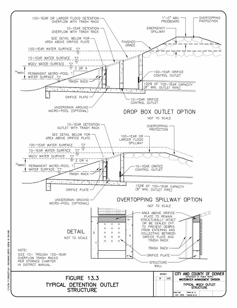
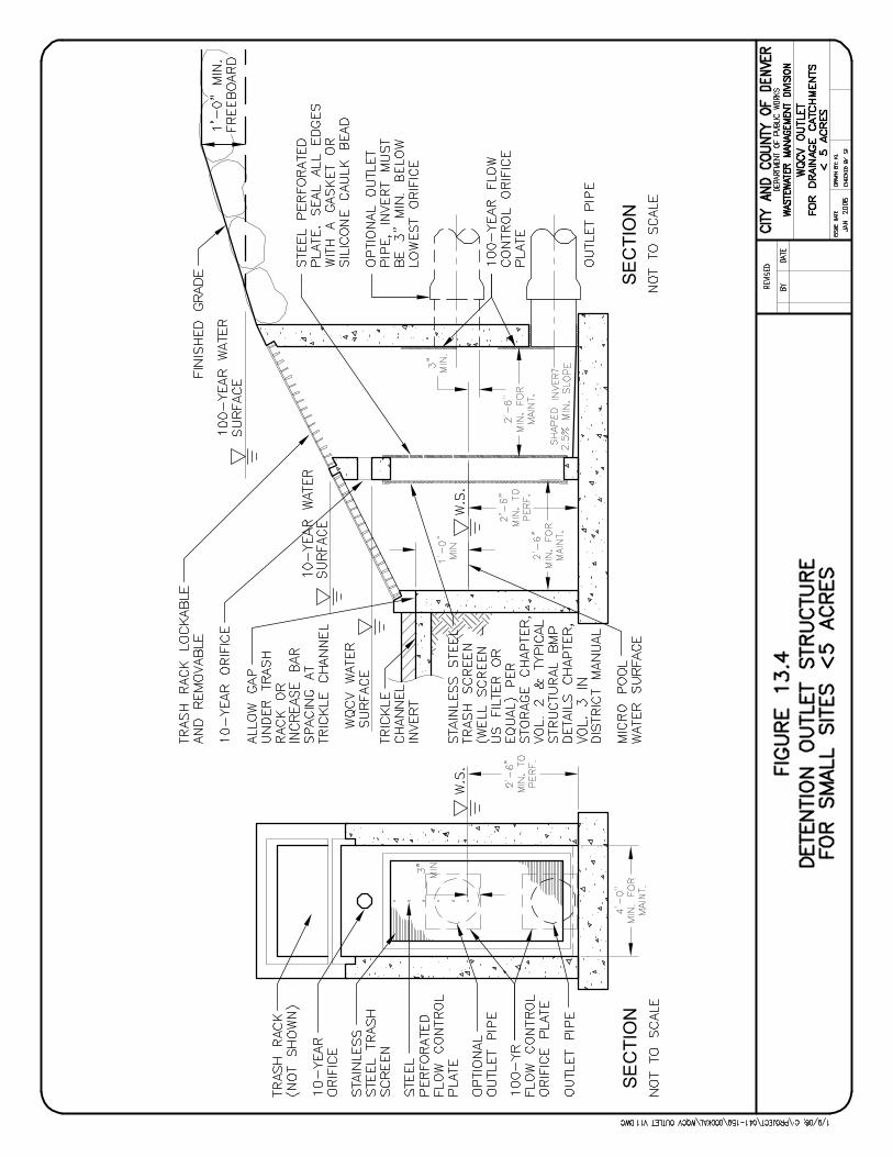
SEC
TIO
NSE
CTI
ON
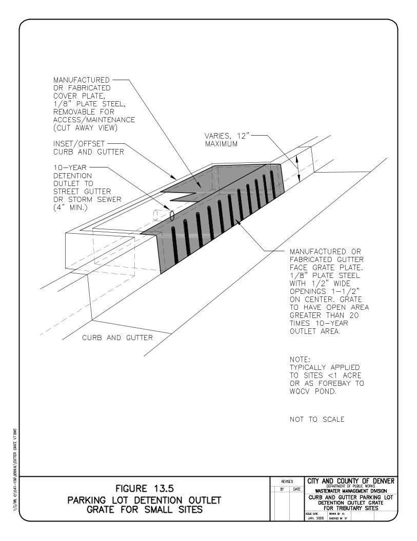
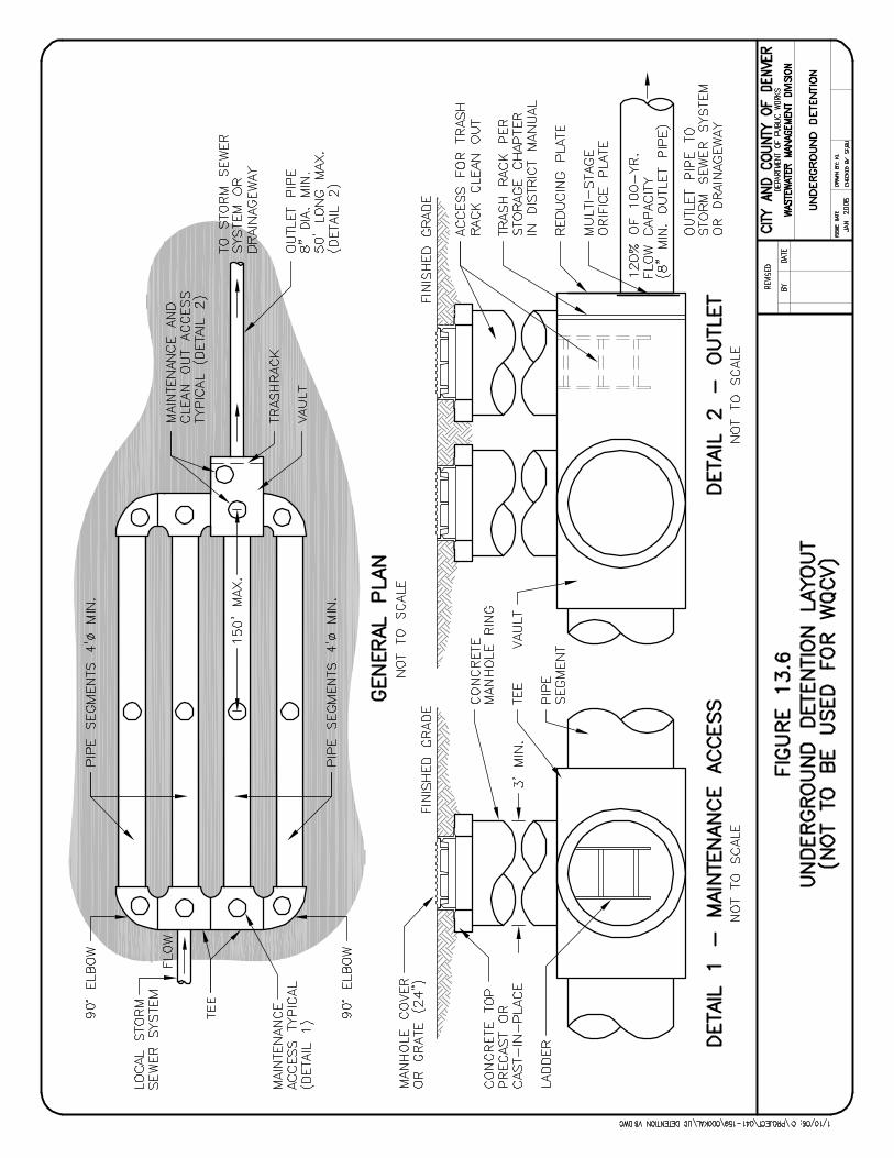

STORM DRAINAGE DESIGN AND TECHNICAL CRITERIA DETENTION (STORAGE)
This page intentionally left blank.
01/2006 DET-20 City and County of Denver
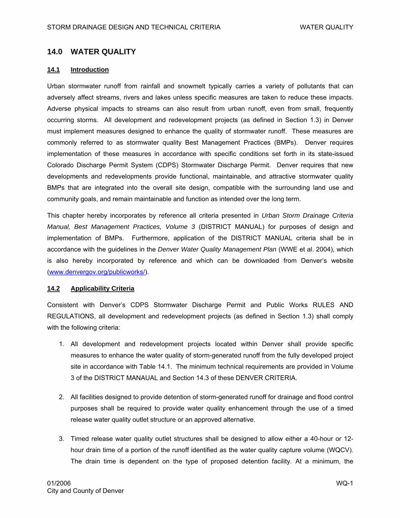
STORM DRAINAGE DESIGN AND TECHNICAL CRITERIA WATER QUALITY
14.0 WATER QUALITY
14.1 Introduction
Urban stormwater runoff from rainfall and snowmelt typically carries a variety of pollutants that can
adversely affect streams, rivers and lakes unless specific measures are taken to reduce these impacts.
Adverse physical impacts to streams can also result from urban runoff, even from small, frequently
occurring storms. All development and redevelopment projects (as defined in Section 1.3) in Denver
must implement measures designed to enhance the quality of stormwater runoff. These measures are
commonly referred to as stormwater quality Best Management Practices (BMPs). Denver requires
implementation of these measures in accordance with specific conditions set forth in its state-issued
Colorado Discharge Permit System (CDPS) Stormwater Discharge Permit. Denver requires that new
developments and redevelopments provide functional, maintainable, and attractive stormwater quality
BMPs that are integrated into the overall site design, compatible with the surrounding land use and
community goals, and remain maintainable and function as intended over the long term.
This chapter hereby incorporates by reference all criteria presented in Urban Storm Drainage Criteria
Manual, Best Management Practices, Volume 3 (DISTRICT MANUAL) for purposes of design and
implementation of BMPs. Furthermore, application of the DISTRICT MANUAL criteria shall be in
accordance with the guidelines in the Denver Water Quality Management Plan (WWE et al. 2004), which
is also hereby incorporated by reference and which can be downloaded from Denver’s website
(www.denvergov.org/publicworks/).
14.2 Applicability Criteria
Consistent with Denver’s CDPS Stormwater Discharge Permit and Public Works RULES AND
REGULATIONS, all development and redevelopment projects (as defined in Section 1.3) shall comply
with the following criteria:
1. All development and redevelopment projects located within Denver shall provide specific
measures to enhance the water quality of storm-generated runoff from the fully developed project
site in accordance with Table 14.1. The minimum technical requirements are provided in Volume
3 of the DISTRICT MANAUAL and Section 14.3 of these DENVER CRITERIA.
2. All facilities designed to provide detention of storm-generated runoff for drainage and flood control
purposes shall be required to provide water quality enhancement through the use of a timed
release water quality outlet structure or an approved alternative.
3. Timed release water quality outlet structures shall be designed to allow either a 40-hour or 12-
hour drain time of a portion of the runoff identified as the water quality capture volume (WQCV).
The drain time is dependent on the type of proposed detention facility. At a minimum, the
01/2006 WQ-1 City and County of Denver
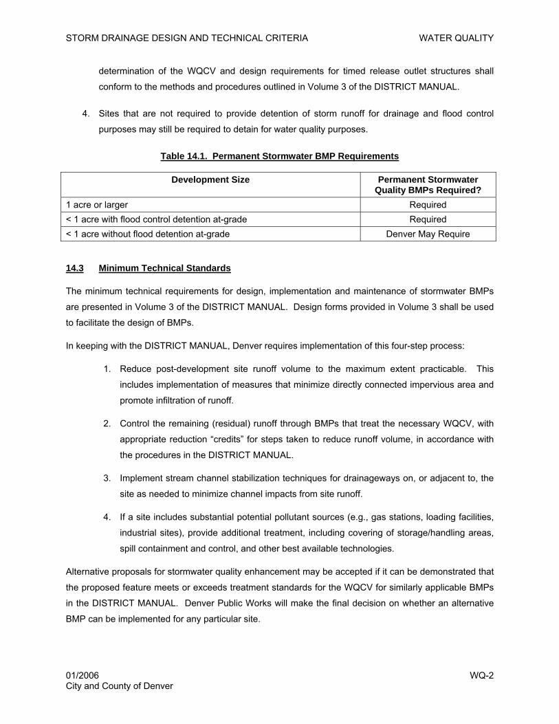
STORM DRAINAGE DESIGN AND TECHNICAL CRITERIA WATER QUALITY
determination of the WQCV and design requirements for timed release outlet structures shall
conform to the methods and procedures outlined in Volume 3 of the DISTRICT MANUAL.
4. Sites that are not required to provide detention of storm runoff for drainage and flood control
purposes may still be required to detain for water quality purposes.
Table 14.1. Permanent Stormwater BMP Requirements
Development Size Permanent Stormwater Quality BMPs Required?
1 acre or larger Required < 1 acre with flood control detention at-grade Required < 1 acre without flood detention at-grade Denver May Require
14.3 Minimum Technical Standards
The minimum technical requirements for design, implementation and maintenance of stormwater BMPs
are presented in Volume 3 of the DISTRICT MANUAL. Design forms provided in Volume 3 shall be used
to facilitate the design of BMPs.
In keeping with the DISTRICT MANUAL, Denver requires implementation of this four-step process:
1. Reduce post-development site runoff volume to the maximum extent practicable. This
includes implementation of measures that minimize directly connected impervious area and
promote infiltration of runoff.
2. Control the remaining (residual) runoff through BMPs that treat the necessary WQCV, with
appropriate reduction “credits” for steps taken to reduce runoff volume, in accordance with
the procedures in the DISTRICT MANUAL.
3. Implement stream channel stabilization techniques for drainageways on, or adjacent to, the
site as needed to minimize channel impacts from site runoff.
4. If a site includes substantial potential pollutant sources (e.g., gas stations, loading facilities,
industrial sites), provide additional treatment, including covering of storage/handling areas,
spill containment and control, and other best available technologies.
Alternative proposals for stormwater quality enhancement may be accepted if it can be demonstrated that
the proposed feature meets or exceeds treatment standards for the WQCV for similarly applicable BMPs
in the DISTRICT MANUAL. Denver Public Works will make the final decision on whether an alternative
BMP can be implemented for any particular site.
01/2006 WQ-2 City and County of Denver

STORM DRAINAGE DESIGN AND TECHNICAL CRITERIA WATER QUALITY
14.4 BMP Selection
Although a variety of BMPs may improve water quality at a given development site, Denver requires that
additional factors related to the development type, aesthetics, surrounding land use, long-term
sustainability and maintenance be taken into account in selection and implementation of stormwater
quality BMPs. The Denver Water Quality Management Plan provides guidance on these additional
factors and Denver’s expectations for BMP designs. Table 14.2 summarizes typical land uses present in
Denver, while Table 14.3 identifies BMPs appropriate for use in these settings, with supplemental
explanation provided in the Denver Water Quality Management Plan.
Additional descriptions and design details for the BMPs in Table 14.3 can be obtained from the DISTRICT
MANUAL. Supplemental details for porous landscape detention and sand filters are provided in Figures
14.1 and 14.2, respectively.
Denver strongly discourages treatment of stormwater in underground vault-type devices due to long-term
maintenance concerns with such devices that are often “out-of-sight, out-of-mind.” Above-ground
treatment of the WQCV is required, even when detention of the minor and major design flows is
underground.
01/2006 WQ-3 City and County of Denver
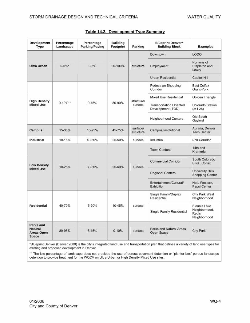
STORM DRAINAGE DESIGN AND TECHNICAL CRITERIA WATER QUALITY
Table 14.2. Development Type Summary
Development Type
Percentage Landscape
Percentage Parking/Paving
Building Footprint Parking
Blueprint Denver* Building Block Examples
Downtown LODO
Employment Portions of Stapleton and Lowry
Ultra Urban 0-5%* 0-5% 90-100% structure
Urban Residential Capitol Hill
Pedestrian Shopping Corridor
East Colfax Grant-York
Mixed Use Residential Golden Triangle
Transportation Oriented Development (TOD)
Colorado Station (at I-25)
High Density Mixed Use 0-10%** 0-15% 80-90% structure/
surface
Neighborhood Centers Old South Gaylord
Campus 15-30% 10-25% 45-75% surface/ structure Campus/Institutional Auraria, Denver
Tech Center
Industrial 10-15% 40-60% 25-50% surface Industrial I-70 Corridor
Town Centers 14th and Krameria
Commercial Corridor South Colorado Blvd., Colfax
Regional Centers University Hills Shopping Center
Low Density Mixed Use 10-25% 30-50% 25-60% surface
Entertainment/Cultural/ Exhibition
Natl. Western, Pepsi Center
Single Family/Duplex Residential
City Park West Neighborhood
Residential 40-70% 5-20% 10-45% surface
Single Family Residential
Sloan’s Lake Neighborhood, Regis Neighborhood
Parks and Natural Areas Open Space
80-95% 5-15% 0-10% surface Parks and Natural Areas Open Space City Park
*Blueprint Denver (Denver 2000) is the city’s integrated land use and transportation plan that defines a variety of land use types for existing and proposed development in Denver.
** The low percentage of landscape does not preclude the use of porous pavement detention or “planter box” porous landscape detention to provide treatment for the WQCV on Ultra Urban or High Density Mixed Use sites.
01/2006 WQ-4 City and County of Denver
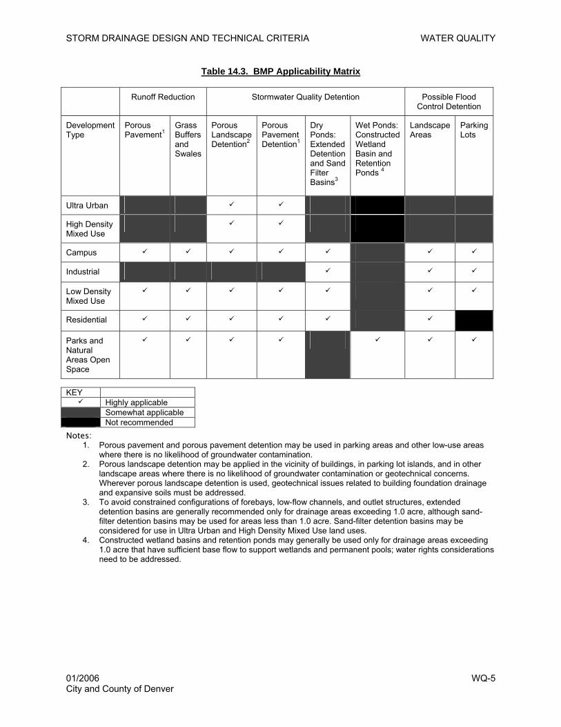
STORM DRAINAGE DESIGN AND TECHNICAL CRITERIA WATER QUALITY
Table 14.3. BMP Applicability Matrix
Runoff Reduction Stormwater Quality Detention Possible Flood Control Detention
Development Type
Porous Pavement1
Grass Buffers and Swales
Porous Landscape Detention2
Porous Pavement Detention1
Dry Ponds: Extended Detention and Sand Filter Basins3
Wet Ponds: Constructed Wetland Basin and Retention Ponds 4
Landscape Areas
Parking Lots
Ultra Urban
High Density Mixed Use
Campus
Industrial
Low Density Mixed Use
Residential
Parks and Natural Areas Open Space
KEY
Highly applicable Somewhat applicable Not recommended Notes:
1. Porous pavement and porous pavement detention may be used in parking areas and other low-use areas where there is no likelihood of groundwater contamination.
2. Porous landscape detention may be applied in the vicinity of buildings, in parking lot islands, and in other landscape areas where there is no likelihood of groundwater contamination or geotechnical concerns. Wherever porous landscape detention is used, geotechnical issues related to building foundation drainage and expansive soils must be addressed.
3. To avoid constrained configurations of forebays, low-flow channels, and outlet structures, extended detention basins are generally recommended only for drainage areas exceeding 1.0 acre, although sand-filter detention basins may be used for areas less than 1.0 acre. Sand-filter detention basins may be considered for use in Ultra Urban and High Density Mixed Use land uses.
4. Constructed wetland basins and retention ponds may generally be used only for drainage areas exceeding 1.0 acre that have sufficient base flow to support wetlands and permanent pools; water rights considerations need to be addressed.
01/2006 WQ-5 City and County of Denver
STORM DRAINAGE DESIGN AND TECHNICAL CRITERIA WATER QUALITY
14.5 Basic Design Principles and Procedure
The Denver Water Quality Management Plan identifies guiding principles for integrating stormwater
quality measures into the overall design of new development or redevelopment. This information is
provided below to further explain Denver’s stormwater management goals.
1. Consider stormwater quality needs early in the design process. Left to the end of site
development, stormwater quality facilities will often be “shoe-horned” into the site, resulting in
forced, constrained approaches. When included in the initial planning for a project, opportunities
to integrate stormwater quality facilities into a site can be fully realized.
2. Take advantage of the entire site when planning for stormwater quality treatment. Spreading runoff over a larger portion of the site can help to reduce undesirable treatment
strategies that rely on proprietary underground treatment devices or deep, walled-in basins that
detract from a site and are difficult to maintain.
3. Reduce runoff rates and volumes to the maximum extent practicable to more closely match natural conditions. To achieve this, place stormwater in contact with the landscape,
minimize directly connected impervious areas, reduce the amount of impervious area (e.g.,
replace low-use or emergency access paved areas with porous pavement) and select treatment
techniques that promote infiltration.
4. Integrate stormwater quality management and flood control, when practical. For example,
in cases where an extended detention basin, retention pond, wetland basin, or sand filter basin is
used to address stormwater quality, any of these basins can be modified to include flood control
detention in addition to the WQCV if space constraints allow.
5. Design attractive stormwater quality facilities that enhance the site, the community, and the environment. Designers should consider surrounding land use type, immediate context, the
prominence of the stormwater quality facility’s location on the site, and the proximity of the site to
important civic spaces.
6. Design sustainable facilities that can be safely maintained. Facility design should provide
adequate maintenance access with a minimum disturbance, disruption, and cost. Designers
need to fully consider how these facilities will be maintained, and what equipment will be
necessary.
7. Design and maintain facilities with public safety in mind. Designers need to consider
minimizing perimeter wall heights, providing railing adjacent to vertical drops of 30” or more, and
ensuring basin edges are designed with gradually sloping banks. They should also avoid walled-
in or steeply sloped, remote basins that could provide haven for illicit activities. Lighting should
be considered an option, where necessary.
01/2006 WQ-6 City and County of Denver
STORM DRAINAGE DESIGN AND TECHNICAL CRITERIA WATER QUALITY
The following design process outlines an approach for implementing these seven principles into the four
minimum technical criteria presented in Section 14.3.
1. Develop an initial site design. This should include a rough layout of lots, buildings, streets,
parking, and landscape areas with a general idea of proposed site grades and an estimate of
approximate areas associated with roofs, streets, walks, parking lots, and landscaping or open
space.
2. Consider the full range of BMP alternatives. Determine which of the seven Development
Types in Table 14.2 most closely match the site and then consider the full range of alternative
approaches for addressing drainage and stormwater quality for the site, including techniques to
reduce runoff and distribute BMPs throughout the site. Reduce runoff volume to the maximum
extent practicable by implementing practices that minimize directly connected impervious area
and promote infiltration. Test the influence of several alternatives on the overall character and
layout of the site, weigh pros and cons of each, and progress towards an optimum approach.
Consider long-term or life-cycle costs in the selection of alternative BMPs. When selecting and
designing BMPs that rely on infiltration (i.e., porous pavement detention, porous landscape
detention), the designer needs to carefully consider geotechnical and foundation issues and the
ability of the property owner to understand and properly maintain these facilities.
3. Pursue a functional distribution of landscape areas. Consider these principles:
• Keep detention basins shallow and consider providing some space for tree and shrub
plantings around their perimeter in areas that do not restrict maintenance access.
• Reserve an initial area about 5 to 15 percent of the size of the impervious area for stormwater
quality treatment. This area may be reduced in later stages of design.
• Minimize exclusive reliance on extended detention basins (primarily for aesthetic and land
use reasons). When included, locate them near a low-lying area of the site away from
pedestrian corridors and gathering places.
• Landscaped areas/grass buffers, porous landscape and porous pavement areas should be
distributed throughout the site. See the Implementation Details section of Chapter 6 of the
Denver Water Quality Management Plan for several examples of how porous landscape
detention facilities can be configured adjacent to buildings, in parking lots, and in other
landscape areas. In general, it is prudent to locate porous landscape detention in close
proximity to the impervious area being served.
4. Consider surface conveyance as an alternative to pipes. Conveying flows on the surface is
the best method for getting runoff to porous landscape and porous pavement detention because it
allows the facilities to be shallow. If flow can be conveyed on the surface in grass swales or in
01/2006 WQ-7 City and County of Denver

STORM DRAINAGE DESIGN AND TECHNICAL CRITERIA WATER QUALITY
strips of modular block porous pavement, additional stormwater quality benefits will accrue and
the required WQCV will be reduced. If runoff must be conveyed under the surface in a pipe, area
inlets within a landscaped area are preferred over street or curb inlets, since this gives runoff a
chance to sheet flow through vegetation and infiltrate prior to entering the storm sewer. The
basin or channel receiving these flows must be deep enough to allow the opposite end of the pipe
to empty.
5. Integrate stormwater quality and flood control detention. Identify flood control detention
requirements, water quality treatment requirements and opportunities to integrate these functions
into multi-purpose facilities.
6. Tailor approach to the specific pollutants of concern. If downstream receiving waters are
threatened by specific stormwater constituents, such as lakes threatened by excessive
phosphorus loading leading to eutrophication, provide BMPs that are particularly effective at
addressing that pollutant.
14.6 Maintenance
Under Denver’s CDPS permit, Denver is required to “ensure” that BMPs are properly maintained.
Maintenance guidelines are provided in both the DISTRICT MANUAL and the Denver Water Quality
Management Plan and are hereby incorporated by reference. For all stormwater management facilities,
Denver requires the following:
1) Facilities must be designed to be readily maintainable with clearly specified long-term
maintenance requirements.
2) Long-term maintenance of the BMP must by provided by the facility owner.
14.7 Checklist and Design Aids
All of the design criteria in this chapter must be followed. Several key considerations that the designer
must take care to address include:
1. Provide stormwater quality treatment in accordance with the requirements in Section 14.2 and
Table 14.2.
2. Provide treatment of the WQCV calculated in accordance with the DISTRICT MANUAL.
3. Provide completed design forms from the DISTRICT MANUAL for selected structural BMPs.
4. Provide schematic details of selected structural BMPs.
5. Design the invert of the inflow pipe to the detention basin to be higher than the water quality level
in detention basins.
01/2006 WQ-8 City and County of Denver
STORM DRAINAGE DESIGN AND TECHNICAL CRITERIA WATER QUALITY
6. Provide water quality outlet structure designs that minimize the number of perforation columns
and keep the diameter of perforation below 2 inches.
7. Design forebays to effectively capture sediment and keep the outlet structure from clogging.
8. Select BMPs with ease of maintenance as a top priority.
9. Provide information on proper maintenance of the BMP(s), including frequency of required
maintenance.
10. If proposed BMP(s) are not selected from the DISTRICT MANUAL, then provide documented
evidence that the BMP can satisfy the minimum technical requirements by meeting or exceeding
similarly applicable BMP(s) in the DISTRICT MANUAL.
01/2006 WQ-9 City and County of Denver
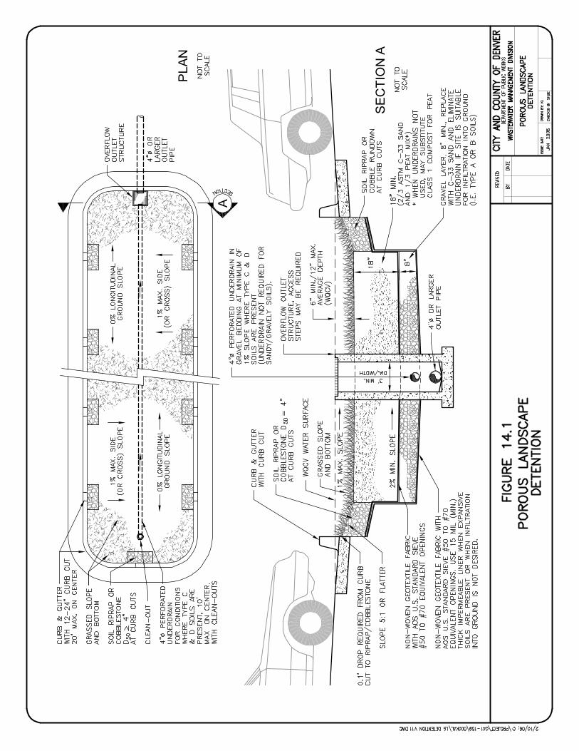
A
PLA
N
SE
CTI
ON
A
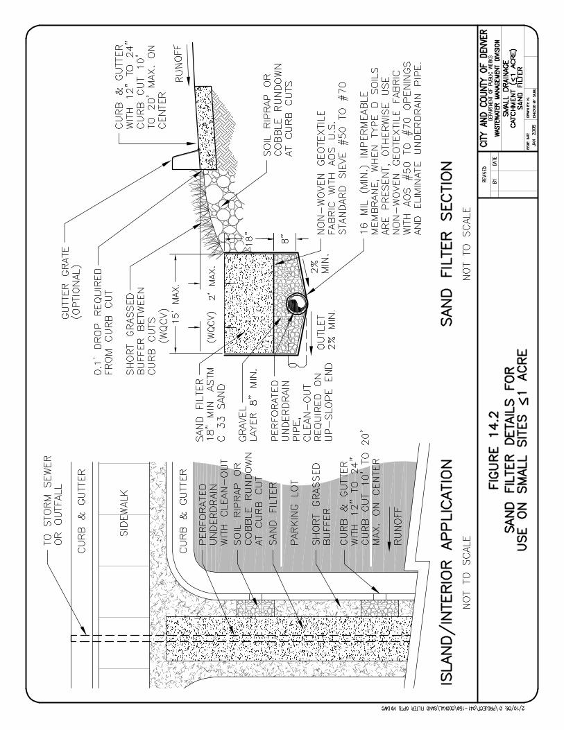
STORM DRAINAGE DESIGN AND TECHNICAL CRITERIA WATER QUALITY
This page intentionally left blank.
01/2006 WQ-12 City and County of Denver
STORM DRAINAGE DESIGN AND TECHNICAL CRITERIA CONSTRUCTION SITE STORMWATER MANAGEMENT AND EROSION CONTROL
15.0 CONSTRUCTION SITE STORMWATER MANAGEMENT AND EROSION CONTROL
15.1 Introduction
All projects located within Denver are required to implement Best Management Practices (BMPs) to
control erosion, sedimentation, and pollutant laden stormwater discharges during construction activities.
This requirement applies to all new development or redevelopment projects (as defined in Section 1.3)
and includes grading projects or demolition where there is to be any excavation, trenching or other
disturbance of the existing ground surface.
This chapter identifies the requirements triggering a Construction Activities Stormwater Discharge Permit,
general principles of erosion and sediment control, the submittal requirements for Construction Activities
Stormwater Management Plans and the minimum technical criteria for erosion control at construction
sites. This chapter hereby incorporates by reference all criteria presented in the Urban Storm Drainage
Criteria Manual, Best Management Practices, Volume 3 (DISTRICT MANUAL) for purposes of design and
implementation of construction-related BMPs.
15.2 Permit Triggers
Construction projects are required to obtain a Construction Activities Stormwater Discharge Permit and
submit a Construction Activities Stormwater Management Plan if any of the following criteria are present.
1. The site development is one acre or more.
2. The site development is under one acre in area, but meets one of the following:
a. The site development is part of a larger overall development sale or plan, and the overall
development plan will ultimately disturb one or more acres at full build-out.
b. If two or more adjacent sites are under construction, but not by the same developer or
contractor, and the total area for these sites exceeds one acre, a Construction Activities
Stormwater Discharge Permit may be required for each individual site.
c. The site has been identified by the Department of Public Works as having a significant
potential for erosion, based on site characteristics including topography.
d. The site is known to contain contaminated soils on site or have a pre-existing condition
warranting special care during construction.
e. The site is within the 100-year designated floodplain of a drainageway, or may discharge
runoff directly into “Waters of the State.”
01/2006 ESC-1 City and County of Denver
STORM DRAINAGE DESIGN AND TECHNICAL CRITERIA CONSTRUCTION SITE STORMWATER MANAGEMENT AND EROSION CONTROL
In addition to permits from Denver, Colorado law also requires that construction projects that exceed one
acre of disturbance area, or are part of a one acre or larger development or sale plan, obtain a
“Stormwater Discharge Permit Associated with Construction Activities” from the Colorado Department of
Public Health and Environment (CDPHE). Information on the State issued permit may be obtained from
the Permits and Enforcement Section of the Water Quality Control Division, CDPHE. It is important to
note that conditions triggering a permit for Denver are more stringent than CDPHE requirements. Denver
permits are triggered based on site size rather than disturbed area.
For a construction project that meets both CDPHE’s and Denver’s permit triggers, separate permits from
each jurisdiction are required.
15.3 Basis of Site Size Determination
The site acreage used to determine a requirement for the Construction Activities Stormwater Discharge
Permit is based on the total area of the project site. If work is also occurring within the right-of-way
(ROW) adjacent to the site, this area of impact must also be included.
To determine the area for utility and street improvement projects, the following criteria shall be followed:
1. If the project does not fall within public ROW,
a. Define the construction limits of the project.
b. Include all construction areas involved with the project.
c. Include all areas to be used for equipment or material storage.
d. Indicate the calculated disturbance area enclosed by the construction limits.
2. If the project falls within public ROW, the area is calculated as follows:
Area = (ROW Width x Project Length) + Areas Used for Contractor Laydown
If the site area, as defined by the above procedures, equals one acre or more, a Construction Activities
Stormwater Discharge Permit is required. Utility construction plans for a development site already
covered by a Department of Public Works-issued Construction Activities Stormwater Discharge Permit
are bound by the requirements of that permit and will not require a separate permit.
15.4 Technical and Regulatory Standards
At a minimum, erosion and sediment control BMPs shall be designed, implemented and maintained in
accordance with the Volume 3, Best Management Practices of the DISTRICT MANUAL.
01/2006 ESC-2 City and County of Denver
STORM DRAINAGE DESIGN AND TECHNICAL CRITERIA CONSTRUCTION SITE STORMWATER MANAGEMENT AND EROSION CONTROL
The minimum regulatory standards that shall be followed include:
• Chapter 10, “Water Quality Grading and Erosion Control” as contained in Department of Public Works
Rules & Regulations Governing Sewerage, Charges and Fees and Management of Wastewater, most
recent version (downloadable from www.denvergov.org/publicworks/).
• “Construction Sites Program” approved response to Part I.B.1.(d) of City and County of Denver
Municipal Stormwater Discharge Permit, CDPHE Permit No. COS-000001, June 9, 1998.
15.5 Principles and Performance Standards
In keeping with the "Construction Sites Program" requirements of Denver’s Stormwater CDPS Permit No.
COS-000001, Denver requires implementation of the following principles at construction sites:
1. Reduce soil loss from all construction sites to the maximum extent practicable.
2. Improve the water quality of storm runoff from construction sites to the maximum extent
practicable.
3. Prevent accumulation of soil and debris originating from construction activity in Denver’s MS4.
4. Prevent discharges of chemicals, chemical wastes and other pollutants from construction sites.
5. Prevent migration of construction debris off site.
6. Prevent damage to properties adjacent to construction sites arising from sediment, debris,
chemical wastes or other pollutants.
7. Protect "state waters" and wetlands from damage caused by erosion, sedimentation, chemical
wastes, or other pollutants arising from construction activity.
These principles shall be achieved by implementation of structural and non-structural BMPs in
accordance with the technical criteria in Volume 3 of the DISTRICT CRITERIA. Factors such as project
type, size, duration, soil type, site slope and proximity to State Waters shall be considered when selecting
BMPs. Guidance for selection of BMPs for construction sites can be obtained from the Stormwater
Quality Control Plan Information Guide (downloadable from www.denvergov.org/publicworks). Denver
has established the following performance standards for erosion and sediment control and requires that
developers meet these standards:
1. All land disturbance activities shall be conducted in a manner that effectively reduces
accelerated soil erosion and reduces the movement or deposition of sediment off site.
2. All land disturbance activities shall be designed, constructed and completed in a manner that
minimizes the duration of land disturbance.
01/2006 ESC-3 City and County of Denver
STORM DRAINAGE DESIGN AND TECHNICAL CRITERIA CONSTRUCTION SITE STORMWATER MANAGEMENT AND EROSION CONTROL
3. Soil stabilization measures shall be implemented within 14 days following completion of
grading activities.
4. Sediment resulting from accelerated soil erosion shall be removed from storm or surface
runoff to the maximum extent practicable prior to leaving the site.
5. All temporary facilities for conveying water around, through or from land disturbed by
construction activity shall be designed and constructed to limit flows to non-erosive velocities.
6. When land disturbing activities are completed, all temporary erosion and sediment control
facilities shall be removed, and the site shall be permanently stabilized.
7. Revegetation of disturbed land shall take place immediately upon completion of construction
activity in that part of the development.
8. All construction wastes, fuel, lubricants, chemical wastes, trash, or debris shall be contained
on site and protected from contact with rainfall or surface runoff.
9. All chemical wastes, trash, debris, or contaminated soil shall be periodically removed from the
construction site and disposed of properly.
To facilitate implementation of these performance standards, Denver recommends implementation of the
following “Minimum Impact Design” practices to minimize erosion, control sedimentation and protect water
quality:
1. Grading, excavation, or clearing and grubbing operations should disturb the smallest practical
area of vegetated, stable soil. Those parts of the site that are not going to be built on
immediately should stay in a natural state until grading is necessary.
2. Existing on-site vegetation should be used as part of the BMPs used to control erosion and
sedimentation and to improve water quality. Existing vegetated stable soil is a good defense
against erosion. Use of existing vegetation for buffer strips is also more cost effective than
attempting to re-establish a vegetated surface.
3. When grading is complete, topsoil stripped off and stockpiled during the grading operations
should be redistributed on the site. The goal is to place most of the original organic material
where it can best be used to establish a good seedbed for revegetation operations.
4. Development of the site should fit the existing topography to the maximum extent practicable
so that grading can match existing contours and existing natural drainage can be preserved.
5. Large sites should be "phased" in such a way that grading, construction, and stabilization are
completed with the phase reaching an acceptable level of stabilization before grading begins
01/2006 ESC-4 City and County of Denver
STORM DRAINAGE DESIGN AND TECHNICAL CRITERIA CONSTRUCTION SITE STORMWATER MANAGEMENT AND EROSION CONTROL
on the next adjoining phase. Ideally, acceptable stabilization is achieved when the density of
the vegetation cover has reached 70 percent.
6. Construction schedules should be as specific as possible and take into account these factors:
a. Site stabilization—minimizing the time between grading startup and application of
seed and mulch after final grade is reached. Seeding, surface roughening, mulching,
or use of geotextiles and matting at the site should be completed within 14 calendar
days after grading operations are finished in any area—even if the area is going to be
built on right away.
b. Time of the year—every effort should be made to avoid site exposure during the peak
rainy period of April 15 through September 15.
c. Growing season—in order to allow for the best possible seeding success and
vegetation growth.
d. Street paving—at least with aggregate as soon as possible after street profiles have
been graded.
7. Fill areas requiring compaction to 90 percent Proctor or higher should be kept to a minimum
as revegetation will be more difficult in compacted soil.
8. Soil stockpiles that will remain for more than 30 days or are close to existing drainageways
need to have stabilization and containment measures installed within 14 days of stockpile
construction.
9. Sites should be designed with specific areas set aside for equipment maintenance and fueling
and designated areas for chemical, fuel and oil, construction materials, and waste storage that
minimize the contact between stored materials and rainfall or runoff. Spill prevention,
containment and cleanup protocols should be prepared and enforced.
For Minimum Impact Design to be most effective, the concepts need to be applied to the earliest design
phases of a development. Because the construction process is not static, these Minimum Impact Design
concepts must evolve along with the design and construction of the project.
15.6 Commonly Observed Problems at Construction Sites
Proper implementation and maintenance of erosion and sediment control measures is critical for the
protection of water quality downstream of construction sites. Failure to properly implement and maintain
these measures can also result in costly fines and other severe penalties. For these reasons, it is
01/2006 ESC-5 City and County of Denver
STORM DRAINAGE DESIGN AND TECHNICAL CRITERIA CONSTRUCTION SITE STORMWATER MANAGEMENT AND EROSION CONTROL
important to plan for and avoid these common problems at construction sites. See Appendix B for
commonly observed problems at construction sites.
15.7 Submittal Requirements
An application for a Construction Activities Stormwater Discharge Permit must be submitted to the
Department of Public Works. This application form, titled “Sewer Use and Drainage Permit Form,” can be
downloaded from Denver’s website (www.denvergov.org/publicworks/). Approval and issuance of a
Construction Activities Stormwater Discharge Permit shall require the submittal and approval of the
Construction Activities Stormwater Management Plan. The narrative report and drawings submitted for
the plan shall have professional engineer (P.E.) stamps and an Owner’s Certification note signed by the
owner, site developer or their authorized agents.
Submittal requirements and additional information concerning the content of plans and reports, standard
notes and other permit-related items are specified in Denver’s Stormwater Quality Control Plan, which
must be downloaded from www.denvergov.org/publicworks/. Compliance with CDPHE submittal
requirements does not ensure compliance with Denver requirements. Issuance of a Denver Construction
Activities Stormwater Discharge Permit does not eliminate the need to obtain a CDPHE permit. In the
event of conflicts, the more stringent requirements shall govern. Submittal requirements for the
Construction Activities Stormwater Management Plan include five copies of the narrative report, five P.E.-
stamped sets of drawings, one copy of miscellaneous technical information and additional documentation
and correspondence, as specified by Public Works (www.denvergov.org/publicworks/).
15.8 Checklist and Design Aids
All of the design criteria in this chapter must be followed. Several important steps include:
1. Determination of whether the site requires a Construction Activities Stormwater Discharge
Permit.
2. Completed application for a Construction Activities Stormwater Discharge Permit.
3. Completed Construction Activities Stormwater Management Plan in accordance with
submittal requirements.
01/2006 ESC-6 City and County of Denver
STORM DRAINAGE DESIGN AND TECHNICAL CRITERIA REFERENCES
16.0 REFERENCES
16.1 Primary References
Urban Drainage and Flood Control District. 1999. Urban Storm Drainage Criteria Manual, Volume 3.
Denver, CO: Urban Drainage and Flood Control District. Website: www.udfcd.org.
Urban Drainage and Flood Control District. 2001. Urban Storm Drainage Criteria Manual, Volumes 1-2.
Denver, CO: Urban Drainage and Flood Control District. Website: www.udfcd.org.
Wright Water Engineers, Inc., Muller Engineering, Wenk Associates, Matrix Design Group and Smith
Environmental, 2004. Denver Water Quality Management Plan. Denver, CO: City and County of
Denver Wastewater Management Division. Website: www.denvergov.org/publicworks/.
16.2 Supplemental References
American Association of State Highway and Transportation Officials (AASHTO). 2002. Standard
Specifications for Highway Bridges, 17th Edition.
American Concrete Pipe Association. 2000. Concrete Pipe Design Manual. Arlington, Virginia:
American Concrete Pipe Association.
American Society of Civil Engineers and Water Environment Federation (ASCE and WEF). 1992. Design
and Construction of Urban Stormwater Management Systems. ASCE Manual and Reports of
Engineering Practice No. 77 and WEF Manual of Practice FD-20. New York, NY: ASCE and
Alexandria, VA: WEF.
City and County of Denver Office of Emergency Management and Urban Drainage and Flood Control
District. 2003. City and County of Denver Flood Protection Handbook. Denver, CO: City and
County of Denver.
City and County of Denver, Department of Public Works, Engineering Division. 2003. Storm Drainage
and Sanitary Construction Details and Technical Specifications. Denver, CO: City and County of
Denver.
City and County of Denver, Department of Public Works, Wastewater Management Division. 2003. “Rules
and Regulations Governing Sewerage Charges and Fees and Management of Wastewater” and
Chapter 56, Articles 91 through 107, Revised Municipal Code.
City and County of Denver, Department of Public Works, Wastewater Management Division. 2000.
Stormwater Quality Control Plans: An Information Guide. Denver, CO: City and County of
Denver. Website: www.denvergov.org/publicworks/.
01/2006 REF-1 City and County of Denver
STORM DRAINAGE DESIGN AND TECHNICAL CRITERIA REFERENCES
City and County of Denver. 2000. Blueprint Denver, An Integrated Land Use and Transportation Plan.
Denver, CO: City and County of Denver.
City and County of Denver. 2005. Article V. Floodplain Management, Chapter 56, Revised Municipal
Code, City and County of Denver, codified through October 17, 2005. (Incorporates Ordinances
No. 158-86, § 1, 3-17-86; Ord. No. 711-94, § 1, 9-6-94; Ord. No. 464-98, § 11, 7-6-98)
Colorado Department of Public Health and Environment (CDPHE). 2003. Authorization to Discharge
Under the Colorado Discharge Permit System, City and County of Denver, Permit No. COS-
000001. Denver, CO: Colorado Department of Public Health and Environment.
Colorado Department of Transportation. 2000. 2000 M-Standard (Miscellaneous Standard) Plans.
www.dot.state.co.us/DesignSupport/.
Colorado Water Conservation Board (CWCB). 1983. Colorado Flood Proofing District Manual.
Division of Water Resources, Office of the State Engineer (SEO). 1988. Rules and Regulations for Dam
Safety and Dam Construction, 2 CCR 402-1.
Ginsberg, A. 1987. HY8 Culvert Analysis Microcomputer Program Applications Guide. Washington, DC:
U.S. Department of Transportation, Federal Highway Administration.
International Code Council. 2003. International Building Code.
Muller Engineering. 2005. Arapahoe County Storm Drainage Criteria Manual. Draft.
Muller Engineering. 2005. Douglas County Storm Drainage Criteria Manual. Draft.
National Oceanic and Atmospheric Administration (NOAA). 1973. Precipitation-Frequency Atlas of the
Western United States, Volume III-Colorado. Washington, D.C.: U.S. Department of Commerce,
National Weather Service.
Simons Li and Associates. 1981. Design Guidelines and Criteria for Channels and Hydraulic Structures
on Sandy Soil.
U.S. Federal Highway Administration (FHWA). 1985. Hydraulic Design of Highway Culverts. Hydraulic
Design Series No. 5. Washington, DC: U.S. Department of Transportation, Federal Highway
Administration.
Urban Drainage and Flood Control District. 2005. District Maintenance Eligibility Guidelines.
Downloadable from www.udfcd.org.
Water Environment Federation and American Society of Civil Engineers. 1998. Urban Runoff Quality
Management. WEF Manual of Practice No. 23 and ASCE Manual and Report on Engineering
Practice No. 87. Alexandria, VA: Water Environment Federation.
01/2006 REF-2 City and County of Denver
STORM
01/200City and Co
DRAINAGE DESIGN AND TECHNICAL CRITERIA APPENDIX A
6 APP A-1 unty of Denver
APPENDIX A. STANDARD FORMS
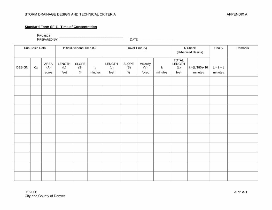
STORM DRAINAGE DESIGN AND TECHNICAL CRITERIA APPENDIX A
Standard Form SF-1. Time of Concentration
PROJECT _________________________________ PREPARED BY _________________________________ DATE__________________
Sub-Basin Data Initial/Overland Time (ti) Travel Time (tt) tc Check (Urbanized Basins)
Final tc Remarks
DESIGN C5
AREA (A)
LENGTH (L)
SLOPE (S) ti
LENGTH (L)
SLOPE (S)
Velocity (V) tt
TOTAL LENGTH
(L) tc=(L/180)+10 tc = ti + tt
acres feet % minutes feet % ft/sec minutes feet minutes minutes
01/2006 APP A-1 City and County of Denver
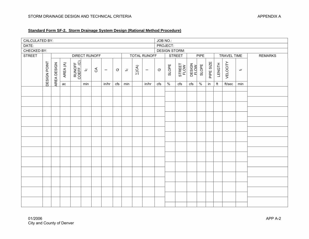
STORM DRAINAGE DESIGN AND TECHNICAL CRITERIA APPENDIX A
Standard Form SF-2. Storm Drainage System Design (Rational Method Procedure)
CALCULATED BY: JOB NO.: DATE: PROJECT: CHECKED BY: DESIGN STORM:
DIRECT RUNOFF TOTAL RUNOFF STREET PIPE TRAVEL TIME REMARKS
AR
EA
(A)
RU
NO
FF
CO
EFF
. (C
)
t C CA
I Q
t C
∑(C
A)
I Q
SLO
PE
STR
EE
T FL
OW
DE
SIG
N
FLO
W
SLO
PE
PIP
E S
IZE
LEN
GTH
VE
LOC
ITY
t t
STREET
DE
SIG
N P
OIN
T
AR
EA
DE
SIG
N
ac min in/hr cfs min in/hr cfs % cfs cfs % in ft ft/sec min
01/2006 APP A-2 City and County of Denver

DRAINAGE DESIGN AND TECHNICAL CRITERIA APPENDIX A
6 APP A-3 unty of Denver
This page intentionally left blank.
STORM
01/200City and Co
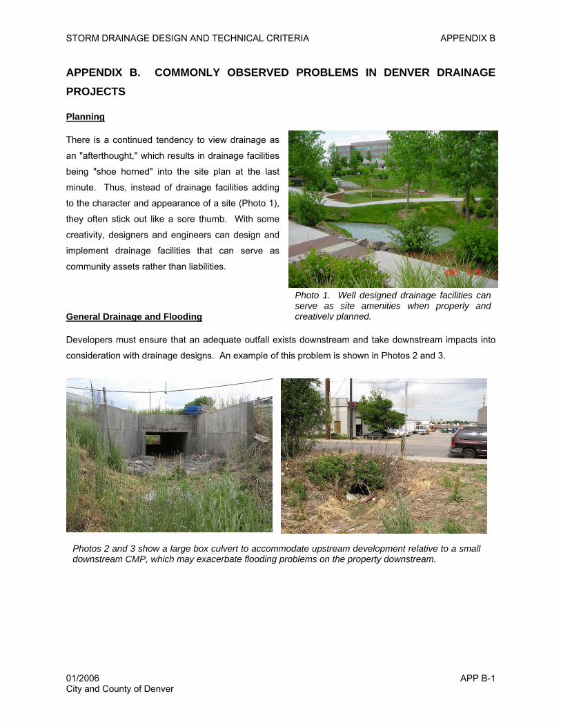
STORM DRAINAGE DESIGN AND TECHNICAL CRITERIA APPENDIX B
APPENDIX B. COMMONLY OBSERVED PROBLEMS IN DENVER DRAINAGE PROJECTS
Planning
There is a continued tendency to view drainage as
an "afterthought," which results in drainage facilities
being "shoe horned" into the site plan at the last
minute. Thus, instead of drainage facilities adding
to the character and appearance of a site (Photo 1),
they often stick out like a sore thumb. With some
creativity, designers and engineers can design and
implement drainage facilities that can serve as
community assets rather than liabilities.
Photo 1. Well designed drainage facilities can serve as site amenities when properly and creatively planned.General Drainage and Flooding
Developers must ensure that an adequate outfall exists downstream and take downstream impacts into
consideration with drainage designs. An example of this problem is shown in Photos 2 and 3.
Photos 2 and 3 show a large box culvert to accommodate upstream development relative to a small downstream CMP, which may exacerbate flooding problems on the property downstream.
01/2006 APP B-1 City and County of Denver
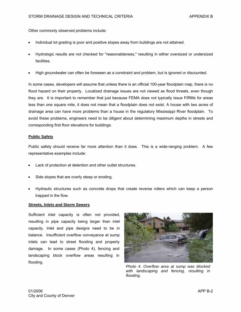
STORM DRAINAGE DESIGN AND TECHNICAL CRITERIA APPENDIX B
Other commonly observed problems include:
• Individual lot grading is poor and positive slopes away from buildings are not attained.
• Hydrologic results are not checked for "reasonableness," resulting in either oversized or undersized
facilities.
• High groundwater can often be foreseen as a constraint and problem, but is ignored or discounted.
In some cases, developers will assume that unless there is an official 100-year floodplain map, there is no
flood hazard on their property. Localized drainage issues are not viewed as flood threats, even though
they are. It is important to remember that just because FEMA does not typically issue FIRMs for areas
less than one square mile, it does not mean that a floodplain does not exist. A house with two acres of
drainage area can have more problems than a house in the regulatory Mississippi River floodplain. To
avoid these problems, engineers need to be diligent about determining maximum depths in streets and
corresponding first floor elevations for buildings.
Public Safety
Public safety should receive far more attention than it does. This is a wide-ranging problem. A few
representative examples include:
• Lack of protection at detention and other outlet structures.
• Side slopes that are overly steep or eroding.
• Hydraulic structures such as concrete drops that create reverse rollers which can keep a person
trapped in the flow.
Streets, Inlets and Storm Sewers
Sufficient inlet capacity is often not provided,
resulting in pipe capacity being larger than inlet
capacity. Inlet and pipe designs need to be in
balance. Insufficient overflow conveyance at sump
inlets can lead to street flooding and property
damage. In some cases (Photo 4), fencing and
landscaping block overflow areas resulting in
flooding. Photo 4. Overflow area at sump was blocked with landscaping and fencing, resulting in flooding.
01/2006 APP B-2 City and County of Denver
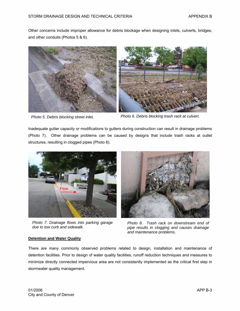
STORM DRAINAGE DESIGN AND TECHNICAL CRITERIA APPENDIX B
Other concerns include improper allowance for debris blockage when designing inlets, culverts, bridges,
and other conduits (Photos 5 & 6).
Inadequate gutter capacity or modifications to gutters during construction can result in drainage problems
(Photo 7). Other drainage problems can be caused by designs that include trash racks at outlet
structures, resulting in clogged pipes (Photo 8).
Photo 6. Debris blocking trash rack at culvert. Photo 5. Debris blocking street inlet.
Flow
Photo 7. Drainage flows into parking garage due to low curb and sidewalk.
Photo 8. Trash rack on downstream end of pipe results in clogging and causes drainage and maintenance problems.
Detention and Water Quality
There are many commonly observed problems related to design, installation and maintenance of
detention facilities. Prior to design of water quality facilities, runoff reduction techniques and measures to
minimize directly connected impervious area are not consistently implemented as the critical first step in
stormwater quality management.
01/2006 APP B-3 City and County of Denver
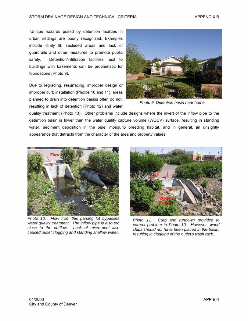
STORM DRAINAGE DESIGN AND TECHNICAL CRITERIA APPENDIX B
Unique hazards posed by detention facilities in
urban settings are poorly recognized. Examples
include dimly lit, secluded areas and lack of
guardrails and other measures to promote public
safety. Detention/infiltration facilities next to
buildings with basements can be problematic for
foundations (Photo 9).
Photo 9. Detention basin near home.
Due to regrading, resurfacing, improper design or
improper curb installation (Photos 10 and 11), areas
planned to drain into detention basins often do not,
resulting in lack of detention (Photo 12) and water
quality treatment (Photo 13). Other problems include designs where the invert of the inflow pipe to the
detention basin is lower than the water quality capture volume (WQCV) surface, resulting in standing
water, sediment deposition in the pipe, mosquito breeding habitat, and in general, an unsightly
appearance that detracts from the character of the area and property values.
Photo 10. Flow from this parking lot bypasses water quality treatment. The inflow pipe is also too close to the outflow. Lack of micro-pool also caused outlet clogging and standing shallow water.
Flow
Wood Chips
Photo 11. Curb and rundown provided to correct problem in Photo 10. However, wood chips should not have been placed in the basin, resulting in clogging of the outlet’s trash rack.
01/2006 APP B-4 City and County of Denver
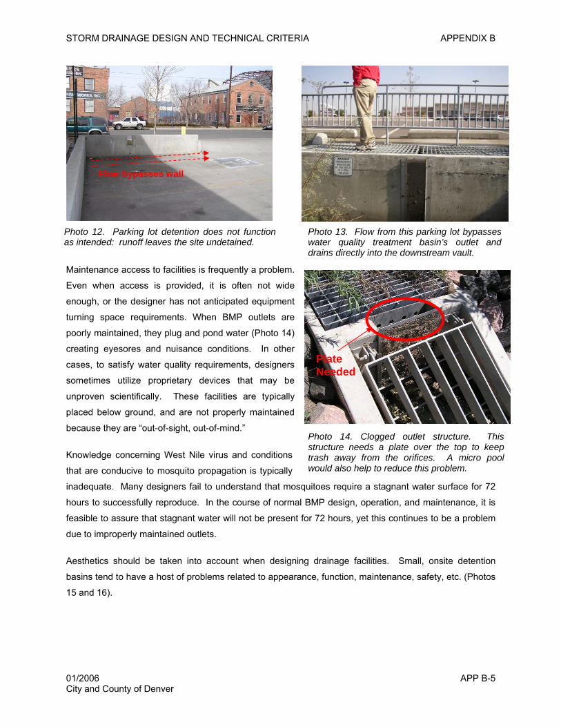
STORM DRAINAGE DESIGN AND TECHNICAL CRITERIA APPENDIX B
Flow bypasses wall
APP B-5 City and County of Denver
Photo 14. Clogged outlet structure. This structure needs a plate over the top to keep trash away from the orifices. A micro pool would also help to reduce this problem.
Plate Needed
Maintenance access to facilities is frequently a problem.
Even when access is provided, it is often not wide
enough, or the designer has not anticipated equipment
turning space requirements. When BMP outlets are
poorly maintained, they plug and pond water (Photo 14)
creating eyesores and nuisance conditions. In other
cases, to satisfy water quality requirements, designers
sometimes utilize proprietary devices that may be
unproven scientifically. These facilities are typically
placed below ground, and are not properly maintained
because they are “out-of-sight, out-of-mind.”
Photo 13. Flow from this parking lot bypasses water quality treatment basin’s outlet and drains directly into the downstream vault.
Photo 12. Parking lot detention does not function as intended: runoff leaves the site undetained.
Knowledge concerning West Nile virus and conditions
that are conducive to mosquito propagation is typically
inadequate. Many designers fail to understand that mosquitoes require a stagnant water surface for 72
hours to successfully reproduce. In the course of normal BMP design, operation, and maintenance, it is
feasible to assure that stagnant water will not be present for 72 hours, yet this continues to be a problem
due to improperly maintained outlets.
Aesthetics should be taken into account when designing drainage facilities. Small, onsite detention
basins tend to have a host of problems related to appearance, function, maintenance, safety, etc. (Photos
15 and 16).
01/2006
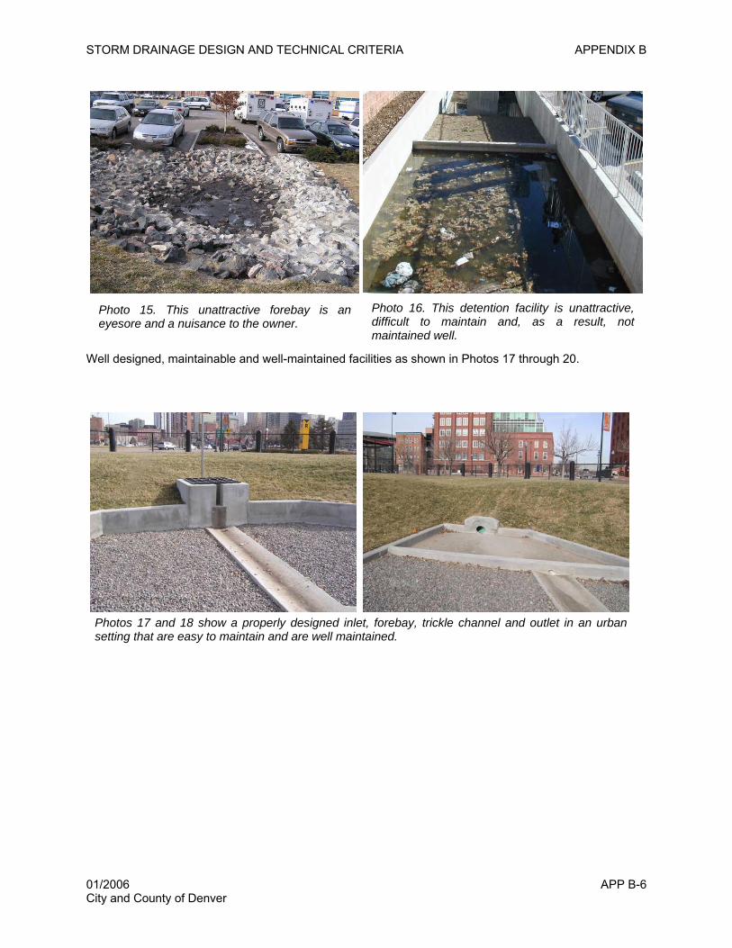
STORM DRAINAGE DESIGN AND TECHNICAL CRITERIA APPENDIX B
01/2006 APP B-6 City and County of Denver
Well designed, maintainable and well-maintained facilities as shown in Photos 17 through 20.
Photo 16. This detention facility is unattractive, difficult to maintain and, as a result, not maintained well.
Photo 15. This unattractive forebay is an eyesore and a nuisance to the owner.
Photos 17 and 18 show a properly designed inlet, forebay, trickle channel and outlet in an urban setting that are easy to maintain and are well maintained.
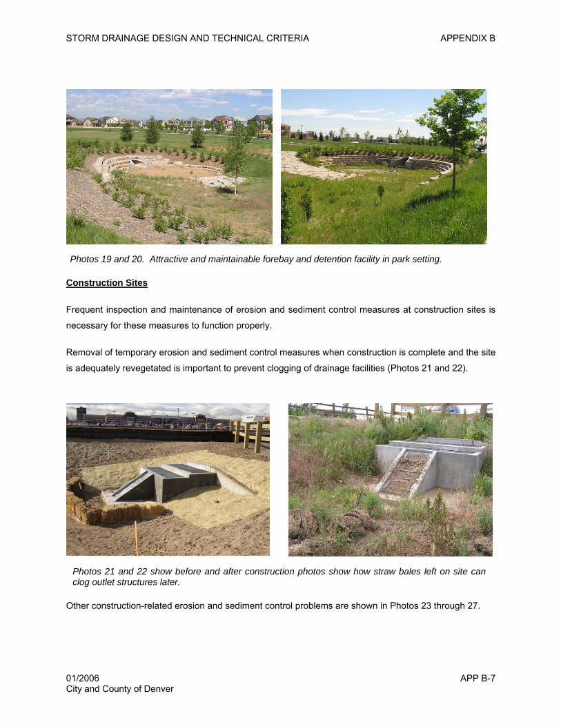
STORM DRAINAGE DESIGN AND TECHNICAL CRITERIA APPENDIX B
Photos 19 and 20. Attractive and maintainable forebay and detention facility in park setting.
Construction Sites
Frequent inspection and maintenance of erosion and sediment control measures at construction sites is
necessary for these measures to function properly.
Removal of temporary erosion and sediment control measures when construction is complete and the site
is adequately revegetated is important to prevent clogging of drainage facilities (Photos 21 and 22).
Photos 21 and 22 show before and after construction photos show how straw bales left on site can clog outlet structures later.
Other construction-related erosion and sediment control problems are shown in Photos 23 through 27.
01/2006 APP B-7 City and County of Denver
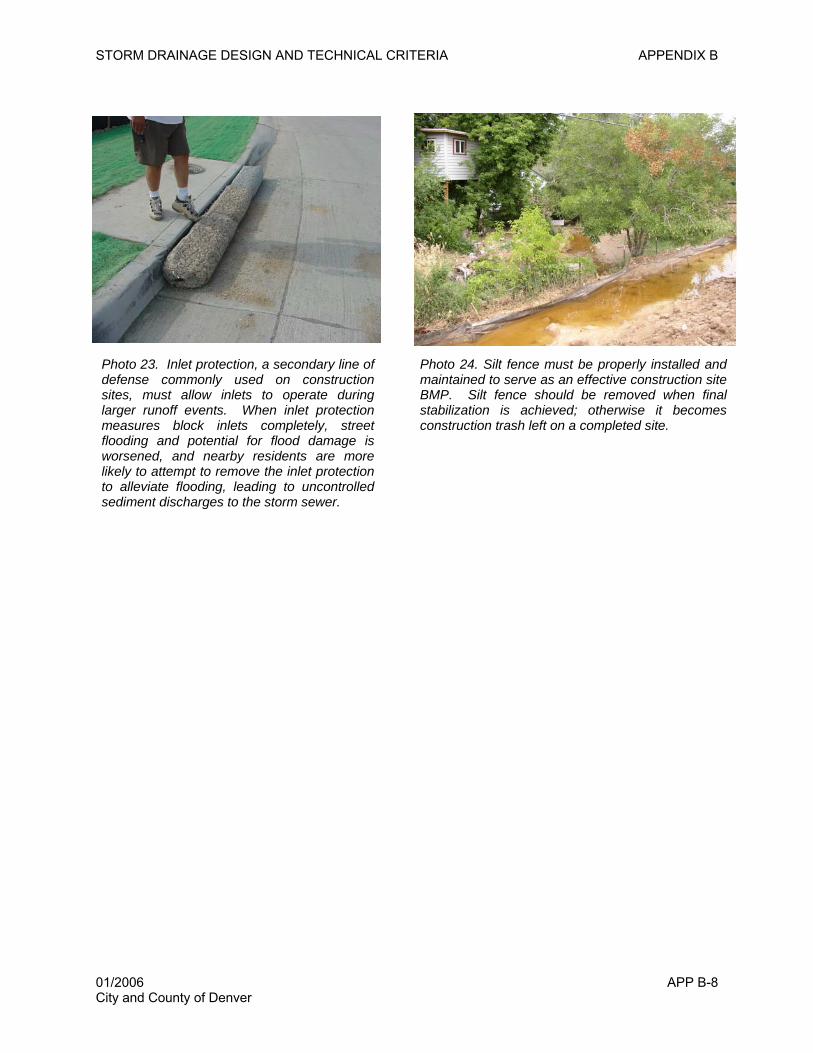
STORM DRAINAGE DESIGN AND TECHNICAL CRITERIA APPENDIX B
Photo 24. Silt fence must be properly installed and maintained to serve as an effective construction site BMP. Silt fence should be removed when final stabilization is achieved; otherwise it becomes construction trash left on a completed site.
Photo 23. Inlet protection, a secondary line of defense commonly used on construction sites, must allow inlets to operate during larger runoff events. When inlet protection measures block inlets completely, street flooding and potential for flood damage is worsened, and nearby residents are more likely to attempt to remove the inlet protection to alleviate flooding, leading to uncontrolled sediment discharges to the storm sewer.
01/2006 APP B-8 City and County of Denver
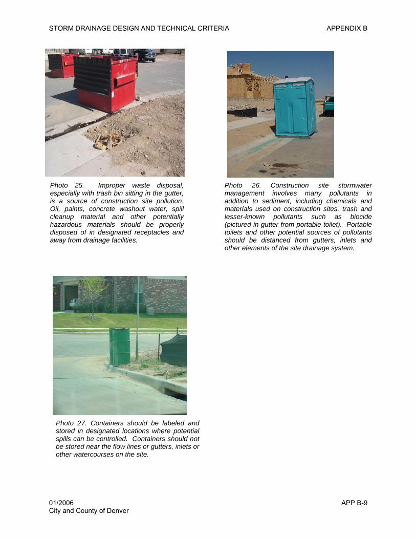
STORM DRAINAGE DESIGN AND TECHNICAL CRITERIA APPENDIX B
01/2006 APP B-9 City and County of Denver
Photo 25. Improper waste disposal, especially with trash bin sitting in the gutter, is a source of construction site pollution. Oil, paints, concrete washout water, spill cleanup material and other potentially hazardous materials should be properly disposed of in designated receptacles and away from drainage facilities.
Photo 26. Construction site stormwater management involves many pollutants in addition to sediment, including chemicals and materials used on construction sites, trash and lesser-known pollutants such as biocide (pictured in gutter from portable toilet). Portable toilets and other potential sources of pollutants should be distanced from gutters, inlets and other elements of the site drainage system.
Photo 27. Containers should be labeled and stored in designated locations where potential spills can be controlled. Containers should not be stored near the flow lines or gutters, inlets or other watercourses on the site.