Embed Size (px)
Citation preview
Appliance I
SS
nstallation Guide
L-1035
Legal Information
End-User License AgreementThe use of the products described in these materials is subject to the then current end-user license agreement, which can be found at the Stonesoft website:www.stonesoft.com/en/support/eula.html
Third Party LicensesThe Stonesoft software includes several open source or third-party software packages. The appropriate software licensing information for those products can be found at the Stonesoft website:www.stonesoft.com/en/customer_care/support/third_party_licenses.html
U.S. Government AcquisitionsIf Licensee is acquiring the Software, including accompanying documentation on behalf of the U.S. Government, the following provisions apply. If the Software is supplied to the Department of Defense (“DoD”), the Software is subject to “Restricted Rights”, as that term is defined in the DOD Supplement to the Federal Acquisition Regulations (“DFAR”) in paragraph 252.227-7013(c) (1). If the Software is supplied to any unit or agency of the United States Government other than DOD, the Government’s rights in the Software will be as defined in paragraph 52.227-19(c) (2) of the Federal Acquisition Regulations (“FAR”). Use, duplication, reproduction or disclosure by the Government is subject to such restrictions or successor provisions.
Product Export RestrictionsThe products described in this document are subject to export control under the laws of Finland and the European Council Regulation (EC) N:o 1334/2000 of 22 June 2000 setting up a Community regime for the control of exports of dual-use items and technology (as amended). Thus, the export of this Stonesoft software in any manner is restricted and requires a license by the relevant authorities.
General Terms and Conditions of Support and Maintenance ServicesThe support and maintenance services for the products described in these materials are provided pursuant to the general terms for support and maintenance services and the related service description, which can be found at the Stonesoft website:www.stonesoft.com/en/customer_care/support/
Replacement ServiceThe instructions for replacement service can be found at the Stonesoft website:www.stonesoft.com/en/customer_care/support/rma/
Hardware WarrantyThe appliances described in these materials have a limited hardware warranty. The terms of the hardware warranty can be found at the Stonesoft website:www.stonesoft.com/en/customer_care/support/warranty_service/
Trademarks and PatentsThe products described in these materials are protected by one or more of the following European and US patents: European Patent Nos. 1065844, 1189410, 1231538, 1231754, 1259028, 1271283, 1289183, 1289202, 1304830, 1304849, 1313290, 1326393, 1361724, 1379037, and 1379046 and US Patent Nos. 6,650,621; 6,856,621; 6,912,200; 6,996,573; 7,099,284; 7,127,739; 7,130,266; 7,130,305; 7,146,421; 7,162,737; 7,234,166; 7,260,843; 7,280,540; 7,325,248; 7,360,242; 7,386,525; 7,406,534; 7,461,401; 7,573,823; 7,721,084; and 7,739,727 and may be protected by other EU, US, or other patents, or pending applications. Stonesoft, the Stonesoft logo and StoneGate, are all trademarks or registered trademarks of Stonesoft Corporation. All other trademarks or registered trademarks are property of their respective owners.
DisclaimerAlthough every precaution has been taken to prepare these materials, THESE MATERIALS ARE PROVIDED "AS-IS" and Stonesoft makes no warranty to the correctness of information and assumes no responsibility for errors, omissions, or resulting damages from the use of the information contained herein. All IP addresses in these materials were chosen at random and are used for illustrative purposes only.
Copyright © 2013 Stonesoft Corporation. All rights reserved. All specifications are subject to change.
Revision: AIG_SSL-1035_ 20130225
2
IntroductionThank you for choosing a Stonesoft™ appliance. This guide provides instructions for the initial hardware installation and the maintenance of SSL-1035 appliances. See Product Documentation (page 4) for information on other available documentation.The use of the appliance is subject to the acceptance of the End User License Agreement, which can be found at the Stonesoft website.
Contents
Installation Procedure .................. 4 Product Documentation ................ 4 Safety Precautions ....................... 5 Unpacking the Appliance .............. 7 Front Panel .................................. 8 Back Panel .................................. 9 Installing the Interface Module ...... 10 Rack-Mounting............................. 11 Connecting the Cables ................. 15 Configuring the Appliance ............. 20 Managing the Appliance ............... 39 Maintenance Operations............... 41 Disposal Instructions ................... 47
Caution – Never open the covers of the appliance! There are no user serviceable parts inside. Opening the covers may lead to serious injury and will void the warranty. Read the Safety Precautions (page 5) before you conduct any installation or maintenance operations on the appliance.
Introduction 3

Instal lation ProcedureThe appliance installation involves the following mandatory steps:1. If you have purchased a network interface module, install it into
the appliance. See Installing the Interface Module (page 10).
2. Install the appliance into a rack and connect the cables. See Rack-Mounting (page 11) and Connecting the Cables (page 15).
3. Configure the basic system settings (time, interfaces, and routing), and import the license and a certificate. See Configuring the Appliance (page 20).
Product DocumentationThe available PDF documentation can be accessed through the SSL VPN Administrator’s front page. The SSL VPN Administrator also has embedded instructions that you can open by clicking the Help link or question mark icon on the various pages.Install the free Adobe Reader program to view the PDF documents (available at www.adobe.com/reader/).
Appliance Interface Module
4 Installation Procedure
Safety PrecautionsThe following safety information and procedures must be followed whenever working with electronic equipment. However, please be advised that Stonesoft appliances are not end-user serviceable, and you must never open the appliance covers for any reason. Doing so may lead to serious injury and will void any hardware warranty that may be associated with your appliance.
Electrical Safety PrecautionsBasic electrical safety precautions should be followed to protect yourself from harm and the appliance from damage:• Be aware of the locations of the power on/off switch as well as the
room's emergency power-off switch, disconnection switch, or electrical outlet. If an electrical accident occurs, you can then quickly cut power to the system.
• Do not work alone when working with high voltage components.• Use only one hand when working with powered-on electrical
equipment. This is to avoid making a complete circuit, which will cause electrical shock. Use extreme caution when using metal tools, which can easily damage any electrical components or circuit boards they come into contact with.
• Do not use mats designed to decrease electrostatic discharge as protection from electrical shock. Instead, use rubber mats that have been specifically designed as electrical insulators.
• The power supply cord must include a grounding plug and must be plugged into a grounded electrical outlet.
General Safety PrecautionsFollow these rules to ensure general safety:• Keep the area around the appliance clean and free of clutter.• We recommend using a regulating uninterruptible power supply (UPS)
to protect the appliance from power surges and voltage spikes, and to keep your system operating in case of a power failure.
Caution – Never open the appliance covers! There are no user serviceable parts inside. Opening the covers may lead to serious injury and will void the warranty.
Safety Precautions 5
Power Supplies
Appliances with DC Power Supply• The appliance must be used in a restricted access location and the
users must be well-trained to operate it.• The socket-outlet for pluggable equipment must be installed near the
equipment and must be easily accessible.• The appliance inlet must have SPS approval or have, at minimum, a
15 AWG wire provided for the power supply.• The mains supply plug on the power supply cord is the disconnect
device on the appliance. To disconnect the appliance, you must first disconnect the mains and then disconnect the ground.
Appliances with AC Power Supply• The appliance inlet is the disconnect device.
ESD PrecautionsElectrostatic discharge (ESD) is generated by two objects with different electrical charges coming into contact with each other. An electrical discharge is created to neutralize this difference, which can damage electronic components and printed circuit boards. Use a grounded wrist strap designed to prevent static discharge.
Laser PrecautionsClass 1 Laser Product.
Note – Use a UPS (Uninterruptible Power Supply) in critical environments with your Stonesoft appliance. If after a brief power outage your Stonesoft appliance only partially starts up (for example, the power light is on, but the appliance does not connect), turn the appliance off for five seconds and then back on.
Caution – Invisible laser radiation is emitted from the end of the fiber-optic cable and from the fiber port. Do not stare into the beam and avoid direct exposure to the beam.
6 Safety Precautions

Operating PrecautionsCare must be taken to ensure that the cover is in place when the appliance is operating to ensure proper cooling. If this rule is not strictly followed, the warranty may become void. Do not open the power supply casing. Power supplies can only be accessed and serviced by a qualified technician of the manufacturer.
Operating and Storage TemperaturesThe allowed operating temperature of the appliance is 0...+40ºC. The allowed storage temperature is -20...+70ºC. Do not operate or store the appliance in temperatures outside these limits.
Lithium Battery Precautions
For California:Perchlorate Material - special handling may apply. See www.dtsc.ca.gov/hazardouswaste/perchlorate.This notice is required by California Code of Regulations, Title 22, Division 4.5, Chapter 33: Best Management Practices for Perchlorate Materials. This product/part includes a battery that contains Perchlorate material.
Unpacking the ApplianceInspect the box that the appliance was shipped in and any other boxes included in the delivery. The interface module is always delivered in a separate box. Note if any of the boxes are damaged in any way. If the appliance itself or any components delivered with the appliance show any damage, file a damage claim with the carrier who delivered the appliance or the components.
Caution – Do not change the battery; the battery must be replaced by authorized service personnel only. There is a risk of explosion if the battery is incorrectly replaced. The replacement battery must be the same as or the equivalent to the type recommended by the manufacturer. Used batteries must be discarded according to the manufacturer’s instructions. Short-circuiting the battery may heat the battery and cause severe injuries.
Unpacking the Appliance 7
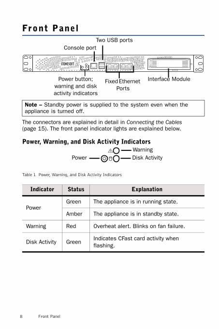
Front Panel
The connectors are explained in detail in Connecting the Cables (page 15). The front panel indicator lights are explained below.
Power, Warning, and Disk Activity Indicators
Note – Standby power is supplied to the system even when the appliance is turned off.
Table 1 Power, Warning, and Disk Activity Indicators
Indicator Status Explanation
PowerGreen The appliance is in running state.
Amber The appliance is in standby state.
Warning Red Overheat alert. Blinks on fan failure.
Disk Activity GreenIndicates CFast card activity when flashing.
Power button;warning and disk activity indicators
Interface ModuleFixed Ethernet Ports
Two USB portsConsole port
Disk ActivityWarning
Power
8 Front Panel

Fixed Ethernet Ports
Back Panel
Table 2 Indicators for Fixed Ethernet Ports
Indicator Status Explanation
Activity Green Link ok, blinks on activity.
LinkGreen 1 Gbps link.
Amber 100 Mbps link.
LinkActivity
AC power connector
CFast Card
Appliance with two DC power supplies CFast Card
Two DC power connectors
Power indicators
(Optional) Grounding screw
Appliance with AC power supply
Back Panel 9
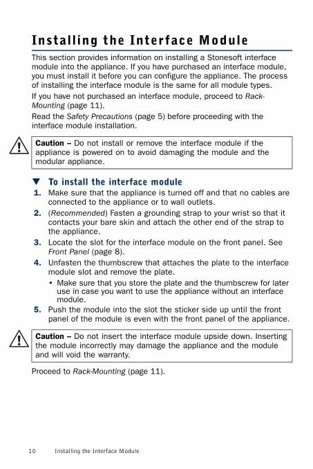
Instal l ing the Interface ModuleThis section provides information on installing a Stonesoft interface module into the appliance. If you have purchased an interface module, you must install it before you can configure the appliance. The process of installing the interface module is the same for all module types.If you have not purchased an interface module, proceed to Rack-Mounting (page 11).Read the Safety Precautions (page 5) before proceeding with the interface module installation.
To install the interface module1. Make sure that the appliance is turned off and that no cables are
connected to the appliance or to wall outlets.2. (Recommended) Fasten a grounding strap to your wrist so that it
contacts your bare skin and attach the other end of the strap to the appliance.
3. Locate the slot for the interface module on the front panel. See Front Panel (page 8).
4. Unfasten the thumbscrew that attaches the plate to the interface module slot and remove the plate.• Make sure that you store the plate and the thumbscrew for later
use in case you want to use the appliance without an interface module.
5. Push the module into the slot the sticker side up until the front panel of the module is even with the front panel of the appliance.
Proceed to Rack-Mounting (page 11).
Caution – Do not install or remove the interface module if the appliance is powered on to avoid damaging the module and the modular appliance.
Caution – Do not insert the interface module upside down. Inserting the module incorrectly may damage the appliance and the module and will void the warranty.
10 Installing the Interface Module
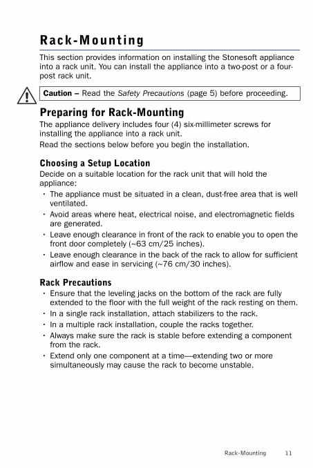
Rack-MountingThis section provides information on installing the Stonesoft appliance into a rack unit. You can install the appliance into a two-post or a four-post rack unit.
Preparing for Rack-MountingThe appliance delivery includes four (4) six-millimeter screws for installing the appliance into a rack unit.Read the sections below before you begin the installation.
Choosing a Setup LocationDecide on a suitable location for the rack unit that will hold the appliance:• The appliance must be situated in a clean, dust-free area that is well
ventilated.• Avoid areas where heat, electrical noise, and electromagnetic fields
are generated.• Leave enough clearance in front of the rack to enable you to open the
front door completely (~63 cm/25 inches).• Leave enough clearance in the back of the rack to allow for sufficient
airflow and ease in servicing (~76 cm/30 inches).
Rack Precautions• Ensure that the leveling jacks on the bottom of the rack are fully
extended to the floor with the full weight of the rack resting on them.• In a single rack installation, attach stabilizers to the rack.• In a multiple rack installation, couple the racks together.• Always make sure the rack is stable before extending a component
from the rack.• Extend only one component at a time—extending two or more
simultaneously may cause the rack to become unstable.
Caution – Read the Safety Precautions (page 5) before proceeding.
Rack-Mounting 11
Appliance Precautions• Determine the placement of each component in the rack before
starting the installation.• Install the heaviest components on the bottom of the rack first, and
then work up.• The appliance must be connected to a grounded power outlet.• Use a regulating uninterruptible power supply (UPS) to protect the
appliance from power surges and voltage spikes, and to keep your system operating in case of a power failure.
• Always keep the rack's front door and all panels and components on the appliances closed when not servicing to maintain proper cooling.
Before Installing the Appliance Into a Rack• Make sure that the rack is securely anchored onto an unmovable
surface or structure before installing the appliance into the rack.• Make sure that the system is adequately supported. Make sure that
all the components are securely fastened to the appliance to prevent components from falling off of the appliance.
• Be sure to install an AC power disconnect for the entire rack assembly. This power disconnect must be clearly marked.
• The rack assembly must be properly grounded to avoid electric shock.• The rack assembly must provide sufficient airflow to the appliance for
proper cooling.
Installing the Appliance Into a Rack
This section provides information on installing the appliance into a rack unit. There are a variety of rack units on the market, so the assembly procedure may differ slightly from what is instructed. If necessary, refer to the instructions that came with the rack unit you are using.If you are installing the appliance into a Telco-type rack, follow the general directions below. The main difference in the installation procedure is whether you are installing the appliance into a four-post rack or a two-post rack. Proceed to one of the following:• Installing the Appliance Into a Four-Post Telco Rack (page 13)• Installing the Appliance Into a Two-Post Telco Rack (page 14)
Note – Do not install the appliance upside down.
12 Rack-Mounting
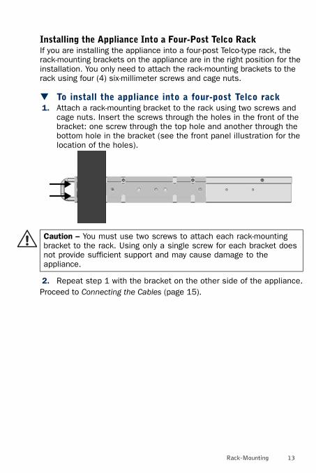
Installing the Appliance Into a Four-Post Telco RackIf you are installing the appliance into a four-post Telco-type rack, the rack-mounting brackets on the appliance are in the right position for the installation. You only need to attach the rack-mounting brackets to the rack using four (4) six-millimeter screws and cage nuts.
To install the appliance into a four-post Telco rack1. Attach a rack-mounting bracket to the rack using two screws and
cage nuts. Insert the screws through the holes in the front of the bracket: one screw through the top hole and another through the bottom hole in the bracket (see the front panel illustration for the location of the holes).
2. Repeat step 1 with the bracket on the other side of the appliance.Proceed to Connecting the Cables (page 15).
Caution – You must use two screws to attach each rack-mounting bracket to the rack. Using only a single screw for each bracket does not provide sufficient support and may cause damage to the appliance.
Rack-Mounting 13
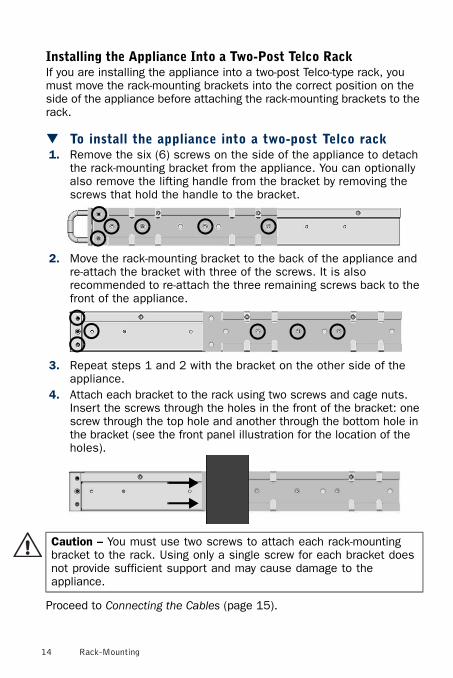
Installing the Appliance Into a Two-Post Telco RackIf you are installing the appliance into a two-post Telco-type rack, you must move the rack-mounting brackets into the correct position on the side of the appliance before attaching the rack-mounting brackets to the rack.
To install the appliance into a two-post Telco rack1. Remove the six (6) screws on the side of the appliance to detach
the rack-mounting bracket from the appliance. You can optionally also remove the lifting handle from the bracket by removing the screws that hold the handle to the bracket.
2. Move the rack-mounting bracket to the back of the appliance and re-attach the bracket with three of the screws. It is also recommended to re-attach the three remaining screws back to the front of the appliance.
3. Repeat steps 1 and 2 with the bracket on the other side of the appliance.
4. Attach each bracket to the rack using two screws and cage nuts. Insert the screws through the holes in the front of the bracket: one screw through the top hole and another through the bottom hole in the bracket (see the front panel illustration for the location of the holes).
Proceed to Connecting the Cables (page 15).
Caution – You must use two screws to attach each rack-mounting bracket to the rack. Using only a single screw for each bracket does not provide sufficient support and may cause damage to the appliance.
14 Rack-Mounting
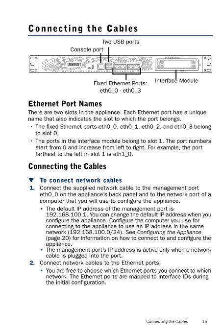
Connecting the Cables
Ethernet Port NamesThere are two slots in the appliance. Each Ethernet port has a unique name that also indicates the slot to which the port belongs.• The fixed Ethernet ports eth0_0, eth0_1, eth0_2, and eth0_3 belong
to slot 0.• The ports in the interface module belong to slot 1. The port numbers
start from 0 and increase from left to right. For example, the port farthest to the left in slot 1 is eth1_0.
Connecting the Cables
To connect network cables1. Connect the supplied network cable to the management port
eth0_0 on the appliance’s back panel and to the network port of a computer that you will use to configure the appliance.• The default IP address of the management port is
192.168.100.1. You can change the default IP address when you configure the appliance. Configure the computer you use for connecting to the appliance to use an IP address in the same network (192.168.100.0/24). See Configuring the Appliance (page 20) for information on how to connect to and configure the appliance.
• The management port’s IP address is active only when a network cable is plugged into the port.
2. Connect network cables to the Ethernet ports.• You are free to choose which Ethernet ports you connect to which
network. The Ethernet ports are mapped to Interface IDs during the initial configuration.
Interface ModuleFixed Ethernet Ports:eth0_0 - eth0_3
Two USB portsConsole port
Connecting the Cables 15
• See the next section for information on connecting network cables to the SFP ports on SFP interface modules.
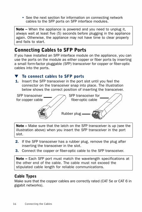
Connecting Cables to SFP PortsIf you have installed an SFP interface module on the appliance, you can use the ports on the module as either copper or fiber ports by inserting a small form-factor pluggable (SFP) transceiver for copper or fiber-optic cables into the ports.
To connect cables to SFP ports1. Insert the SFP transceiver in the port slot until you feel the
connector on the transceiver snap into place. The illustration below shows the correct position of inserting the transceiver.
2. If the SFP transceiver has a rubber plug, remove the plug after inserting the transceiver in the slot.
3. Connect the copper or fiber-optic cable to the SFP transceiver.
Cable TypesMake sure that the copper cables are correctly rated (CAT 5e or CAT 6 in gigabit networks).
Note – When the appliance is powered and you need to unplug it, always wait at least five (5) seconds before plugging in the appliance again. Otherwise, the appliance may not have time to clear properly and fails to start.
Note – Make sure that the latch on the SFP transceiver is up (see the illustration above) when you insert the SFP transceiver in the port slot.
Note – Each SFP port must match the wavelength specifications at the other end of the cable. The cable must not exceed the stipulated cable length for reliable communications.
SFP transceiver for copper cable
SFP transceiver for fiber-optic cable
Rubber plug
16 Connecting the Cables
Speed/Duplex SettingsNetwork cards at both ends of each cable must have identical speed/duplex settings. This also applies to the automatic negotiation setting: if one end of the cable is set to autonegotiate, the other end must also be set to autonegotiate. Gigabit standards require interfaces to use autonegotiation—fixed settings are not allowed at gigabit speeds.
Connecting the Appliance to an AC Power SupplyYour appliance may have either a single AC power supply or two DC power supplies. Proceed to one of the following:• Connecting the Appliance to an AC Power Supply• Connecting the Appliance to DC Power Supplies
Connecting the Appliance to an AC Power Supply
To connect the appliance to an AC power supply1. Connect the power cord to the AC power connector on the back of
the appliance.2. Plug the power cord into a grounded, high-quality power strip that
offers protection from electrical noise and power surges.• We highly recommend using an uninterruptible power supply
(UPS) to ensure continuous operation and minimize the risk of damage to the appliance in case of sudden loss of power.
Proceed to Configuring the Appliance (page 20).
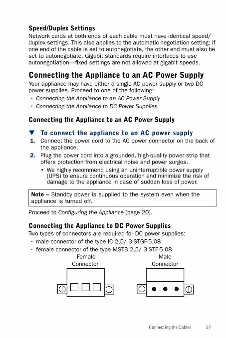
Connecting the Appliance to DC Power SuppliesTwo types of connectors are required for DC power supplies:• male connector of the type IC 2,5/ 3-STGF-5,08• female connector of the type MSTB 2,5/ 3-STF-5,08
Note – Standby power is supplied to the system even when the appliance is turned off.
Female Connector
Male Connector
Connecting the Cables 17
If you have an appliance with two DC power supplies, two male connectors are preinstalled on the back panel of the appliance. You must assemble two female connectors that will connect to the two male connectors.
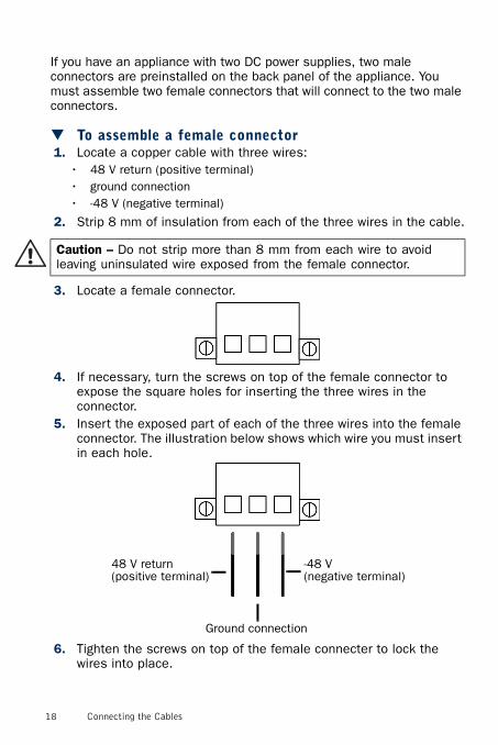
To assemble a female connector1. Locate a copper cable with three wires:
• 48 V return (positive terminal)• ground connection• -48 V (negative terminal)
2. Strip 8 mm of insulation from each of the three wires in the cable.
3. Locate a female connector.
4. If necessary, turn the screws on top of the female connector to expose the square holes for inserting the three wires in the connector.
5. Insert the exposed part of each of the three wires into the female connector. The illustration below shows which wire you must insert in each hole.
6. Tighten the screws on top of the female connecter to lock the wires into place.
Caution – Do not strip more than 8 mm from each wire to avoid leaving uninsulated wire exposed from the female connector.
-48 V(negative terminal)
48 V return (positive terminal)
Ground connection
18 Connecting the Cables
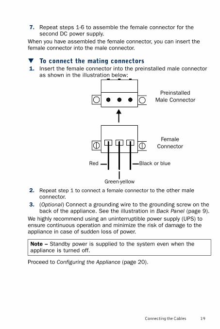
7. Repeat steps 1-6 to assemble the female connector for the second DC power supply.
When you have assembled the female connector, you can insert the female connector into the male connector.
To connect the mating connectors1. Insert the female connector into the preinstalled male connector
as shown in the illustration below:
2. Repeat step 1 to connect a female connector to the other male connector.
3. (Optional) Connect a grounding wire to the grounding screw on the back of the appliance. See the illustration in Back Panel (page 9).
We highly recommend using an uninterruptible power supply (UPS) to ensure continuous operation and minimize the risk of damage to the appliance in case of sudden loss of power.
Proceed to Configuring the Appliance (page 20).
Note – Standby power is supplied to the system even when the appliance is turned off.
Black or blueRed
Green-yellow
Preinstalled Male Connector
Female Connector
Connecting the Cables 19

Configuring the ApplianceBefore the appliance can offer any services to the users, you must configure the networking settings for all interfaces you intend to use.Start by Defining the Basic Settings.
Defining the Basic SettingsThe only interface that is defined when you receive the appliance is the management port eth 0_0 on the appliance’s back panel. The default IP address of the management port is 192.168.100.1. You can change the default IP address and other default settings for the appliance in the Engine Configuration Wizard.
To start the Engine Configuration Wizard1. Connect the supplied null-modem cable to the serial port on the
appliance’s front panel and to a computer that you will use for a terminal connection.
2. On the computer, open a terminal with the following settings: 9600 bps, 8 databits, 1 stopbit, no parity.
3. Turn on the appliance using the power button. The engine bootup process is shown in the Console and, after some time, the Engine Configuration Wizard starts.
To set the keyboard layout1. Highlight the entry field for Keyboard Layout and press ENTER. The
Select Keyboard Layout dialog opens.
1
20 Configuring the Appliance

2. Highlight the correct layout and press ENTER.
To set the engine’s timezone1. Highlight the entry field for Local Timezone and press ENTER.
2. Select the correct timezone in the dialog that opens.
Note – If the desired keyboard layout is not available, use the best-matching available layout, or select US_English.
Note – The timezone setting affects only the way the time is displayed on the engine command line. The actual operation always uses UTC time.
1
Configuring the Appliance 21
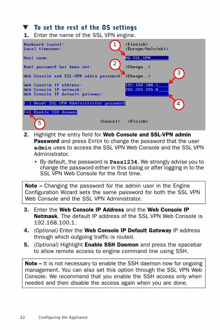
To set the rest of the OS settings1. Enter the name of the SSL VPN engine.
2. Highlight the entry field for Web Console and SSL-VPN admin Password and press ENTER to change the password that the user admin uses to access the SSL VPN Web Console and the SSL VPN Administrator.• By default, the password is Pass1234. We strongly advise you to
change the password either in this dialog or after logging in to the SSL VPN Web Console for the first time.
3. Enter the Web Console IP Address and the Web Console IP Netmask. The default IP address of the SSL VPN Web Console is 192.168.100.1.
4. (Optional) Enter the Web Console IP Default Gateway IP address through which outgoing traffic is routed.
5. (Optional) Highlight Enable SSH Daemon and press the spacebar to allow remote access to engine command line using SSH.
Note – Changing the password for the admin user in the Engine Configuration Wizard sets the same password for both the SSL VPN Web Console and the SSL VPN Administrator.
Note – It is not necessary to enable the SSH daemon now for ongoing management. You can also set this option through the SSL VPN Web Console. We recommend that you enable the SSH access only when needed and then disable the access again when you are done.
1
2
5
3
4
22 Configuring the Appliance
6. Highlight Finish and press ENTER. The Engine Configuration Wizard closes.
Continue by Logging in to the SSL VPN Web Console.
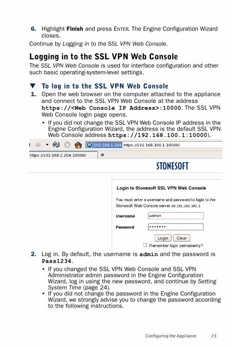
Logging in to the SSL VPN Web ConsoleThe SSL VPN Web Console is used for interface configuration and other such basic operating-system-level settings.
To log in to the SSL VPN Web Console1. Open the web browser on the computer attached to the appliance
and connect to the SSL VPN Web Console at the address https://<Web Console IP Address>:10000. The SSL VPN Web Console login page opens.• If you did not change the SSL VPN Web Console IP address in the
Engine Configuration Wizard, the address is the default SSL VPN Web Console address https://192.168.100.1:10000).
2. Log in. By default, the username is admin and the password is Pass1234.• If you changed the SSL VPN Web Console and SSL VPN
Administrator admin password in the Engine Configuration Wizard, log in using the new password, and continue by Setting System Time (page 24).
• If you did not change the password in the Engine Configuration Wizard, we strongly advise you to change the password according to the following instructions.
Configuring the Appliance 23
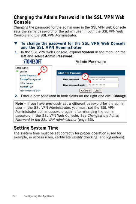
Changing the Admin Password in the SSL VPN Web ConsoleChanging the password for the admin user in the SSL VPN Web Console sets the same password for the admin user in both the SSL VPN Web Console and the SSL VPN Administrator.
To change the password for the SSL VPN Web Console and the SSL VPN Administrator
1. In the SSL VPN Web Console, expand System in the menu on the left and select Admin Password.
2. Enter a new password in both fields on the right and click Change.
Setting System TimeThe system time must be set correctly for proper operation (used for example, in access rules, certificate validity checking, and log entries).
Note – If you have previously set a different password for the admin user in the SSL VPN Administrator, you must set the SSL VPN Administrator admin password again after changing the admin password in the SSL VPN Web Console. See Changing the Admin Password in the SSL VPN Administrator (page 33).
1
2
24 Configuring the Appliance
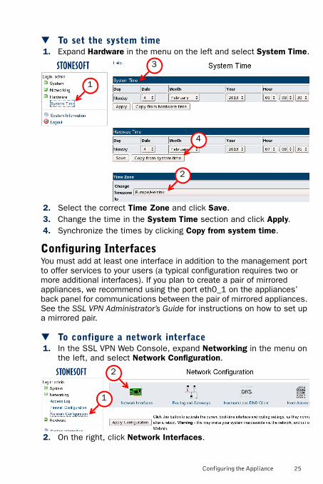
To set the system time1. Expand Hardware in the menu on the left and select System Time.
2. Select the correct Time Zone and click Save.3. Change the time in the System Time section and click Apply.4. Synchronize the times by clicking Copy from system time.
Configuring InterfacesYou must add at least one interface in addition to the management port to offer services to your users (a typical configuration requires two or more additional interfaces). If you plan to create a pair of mirrored appliances, we recommend using the port eth0_1 on the appliances’ back panel for communications between the pair of mirrored appliances. See the SSL VPN Administrator’s Guide for instructions on how to set up a mirrored pair.
To configure a network interface1. In the SSL VPN Web Console, expand Networking in the menu on
the left, and select Network Configuration.
2. On the right, click Network Interfaces.
1
2
3
4
2
1
Configuring the Appliance 25
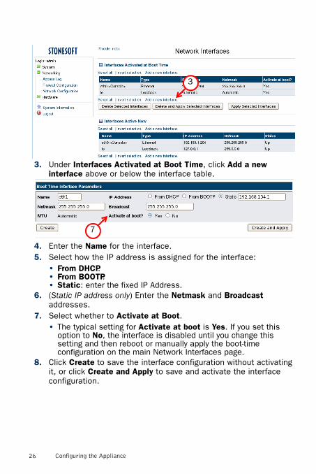
3. Under Interfaces Activated at Boot Time, click Add a new interface above or below the interface table.
4. Enter the Name for the interface.5. Select how the IP address is assigned for the interface:
• From DHCP.• From BOOTP.• Static: enter the fixed IP Address.
6. (Static IP address only) Enter the Netmask and Broadcast addresses.
7. Select whether to Activate at Boot.• The typical setting for Activate at boot is Yes. If you set this
option to No, the interface is disabled until you change this setting and then reboot or manually apply the boot-time configuration on the main Network Interfaces page.
8. Click Create to save the interface configuration without activating it, or click Create and Apply to save and activate the interface configuration.
3
7
26 Configuring the Appliance
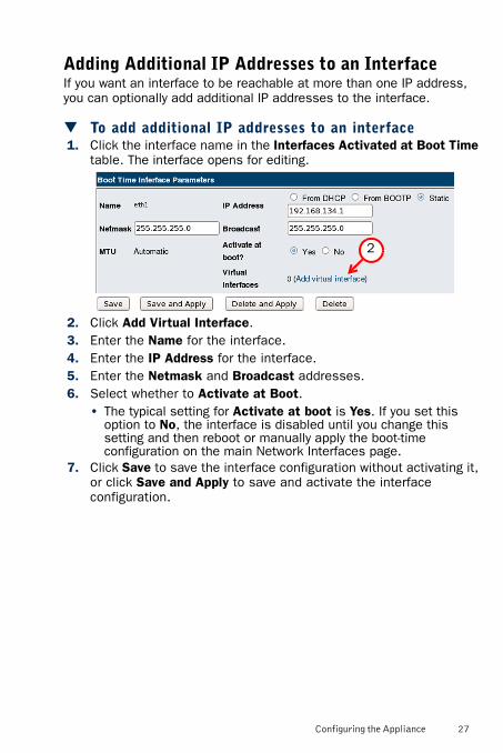
Adding Additional IP Addresses to an InterfaceIf you want an interface to be reachable at more than one IP address, you can optionally add additional IP addresses to the interface.
To add additional IP addresses to an interface1. Click the interface name in the Interfaces Activated at Boot Time
table. The interface opens for editing.
2. Click Add Virtual Interface.3. Enter the Name for the interface.4. Enter the IP Address for the interface.5. Enter the Netmask and Broadcast addresses.6. Select whether to Activate at Boot.
• The typical setting for Activate at boot is Yes. If you set this option to No, the interface is disabled until you change this setting and then reboot or manually apply the boot-time configuration on the main Network Interfaces page.
7. Click Save to save the interface configuration without activating it, or click Save and Apply to save and activate the interface configuration.
2
Configuring the Appliance 27

Configuring Routing
To configure routing1. In the SSL VPN Web Console, under the Networking category in
the menu on the left, select Network Configuration.2. On the right, click Routing and Gateways. The Routing page
opens.
3. Define the Default Router in one of the following ways:• Select None (or from DHCP) if the IP address of the default
gateway is dynamically assigned.• Select Gateway and enter the IP address of your gateway.
4. Select the interface through which the gateway Device is reached.5. (Optional) Configure the following settings to define Static Routes
through a next-hop gateway (such as a router), and/or Local Routes to devices that are connected directly (such as through a hub or directly through a crossover cable):• Interface: Enter the name of the interface used by the route.• Network: Enter the IP address of the network to which the route
belongs.• Netmask: Enter the Netmask.• Gateway: (Static Routes only) Enter the IP address of the next-
hop gateway through which outgoing traffic is routed.6. Click Save.7. Click Return to Network Configuration. You are returned to the
Network Configuration page.8. Click Apply Configuration. The routes added in the Routing
configuration activated at boot time section are activated.
28 Configuring the Appliance
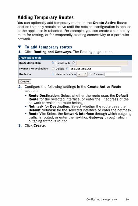
Adding Temporary RoutesYou can optionally add temporary routes in the Create Active Route section that only remain active until the network configuration is applied or the appliance is rebooted. For example, you can create a temporary route for testing, or for temporarily creating connectivity to a particular network.
To add temporary routes1. Click Routing and Gateways. The Routing page opens.
2. Configure the following settings in the Create Active Route section:• Route Destination: Select whether the route uses the Default
Route for the selected interface, or enter the IP address of the network to which the route belongs.
• Netmask for Destination: Select whether the route uses the Default Netmask for the selected interface or enter the netmask.
• Route Via: Select the Network Interface through which outgoing traffic is routed, or enter the next-hop Gateway through which outgoing traffic is routed.
3. Click Create.
Configuring the Appliance 29
Configuring DNS SettingsIf you want services to be available by domain names as well as IP addresses, you must configure the DNS settings as below.
To configure the DNS settings1. In the SSL VPN Web Console, under the Networking category in
the menu on the left, select Network Configuration.2. On the right, click the Hostname and DNS client icon.3. Enter the Hostname of the appliance.4. In DNS Servers, enter the IP addresses of your DNS servers.5. (Optional) In Resolution order, specify the order in which the
addresses are queried from different sources.6. (Optional) In Search domains, select Listed and enter your domain
(for example: example.com).
Generating a Certificate RequestAuthentication in SSL is based on certificates as the proof of identity. The appliance contains a factory-installed certificate that allows testing in a closed network without the need to install an actual working certificate on the appliance. When installing the appliance for other use, you must always generate a working certificate.
The following procedure explains how to generate a certificate request using the tools included with the appliance. You can also generate a certificate request using other tools. The certificate must be in the .pem format. See the SSL VPN Administrator’s Guide for more information on certificates.
Caution – Never use the factory-installed standard keys and certificates for anything other than testing in a closed environment! If you do not generate new keys and certificates, the security of the system is severely compromised.
30 Configuring the Appliance
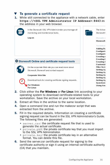
To generate a certificate request1. While still connected to the appliance with a network cable, enter
https://<SSL VPN Administrator IP Address>:8443 as the address in your web browser.
2. Click either the For Windows or For Linux link according to your operating system to download certificate-related tools to your workstation. Save the archive on your local workstation.
3. Extract all files in the archive to the same location.4. Open a command line and run the makecsr script that was
extracted from the archive.5. Fill in the required details. Information on creating a certificate
signing request can be found in the SSL VPN Administrator’s Guide. The following files are generated:• server.csr: the certificate request file that is used to
generate the actual certificate.• private.pk8: the private certificate key that you must import
to the SSL VPN Administrator.• private.key: the private certificate key in an alternative
format. You can delete this file.6. Send the server.csr certificate request for signing to the
certificate authority or sign it using an internal certificate authority (CA) that you maintain.
2
Configuring the Appliance 31

• If the CA is not configured as trusted in the web browser the end-users connect with, the users see a certificate warning that they need to accept to access resources.
• Many commercial certificate authorities are configured as trusted in web browsers by default.
When you have the signed certificate, import it to the SSL VPN Administrator and activate it for the Administration Service and Access Point. See Logging in to the SSL VPN Administrator and Importing Certificate Keys and Certificates (page 35).
Logging in to the SSL VPN AdministratorThe SSL VPN Administrator is used to set up and manage the SSL VPN features.
To log in to the SSL VPN Administrator1. Click Log on on the left, under the title Stonesoft SSL VPN
Administrator.
2. Log in using the password you set for the SSL VPN Web Console and SSL VPN Administrator admin user account.
32 Configuring the Appliance
Changing the Admin Password in the SSL VPN AdministratorBy default, the same password is used to log in to the SSL VPN Web Console and the SSL VPN Administrator as the admin user. We recommend changing the SSL VPN Administrator admin password to a unique password.
To change the admin password in the SSL VPN Administrator
1. When the SSL VPN Administrator opens, scroll down to the bottom of the page.
2. Click Manage Settings. The Settings page opens.3. Scroll down to the Super Administrator Password section.4. (Optional) Deselect Enable Password Policy if you do not want to
require the password to meet specific security requirements.5. Enter the Current Password.6. Enter and confirm a secure New Password.7. Click Save.
After changing the admin password, import your license and the working certificate.
Importing a LicenseFor the initial configuration of the appliance, you must import the SSL VPN license through the SSL VPN Administrator. If you later connect the appliance to the Stonesoft Management Center, you can optionally manage the licenses through the Management Client as well. See the Stonesoft Administrator’s Guide or the Online Help of the Management Client for more information.
Note – If you change the password for the admin user in the SSL VPN Web Console after changing the password for the admin user in the SSL VPN Administrator, the same password is set for the admin user in both the SSL VPN Web Console and the SSL VPN Administrator. You must set the SSL VPN Administrator admin password again after changing the admin password in the SSL VPN Web Console.
Configuring the Appliance 33
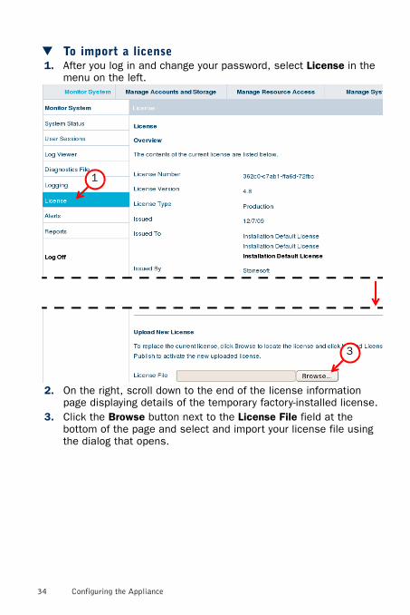
To import a license1. After you log in and change your password, select License in the
menu on the left.
2. On the right, scroll down to the end of the license information page displaying details of the temporary factory-installed license.
3. Click the Browse button next to the License File field at the bottom of the page and select and import your license file using the dialog that opens.
3
1
34 Configuring the Appliance
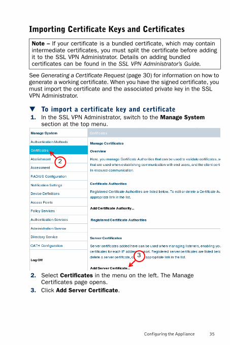
Importing Certificate Keys and Certificates
See Generating a Certificate Request (page 30) for information on how to generate a working certificate. When you have the signed certificate, you must import the certificate and the associated private key in the SSL VPN Administrator.
To import a certificate key and certificate1. In the SSL VPN Administrator, switch to the Manage System
section at the top menu.
2. Select Certificates in the menu on the left. The Manage Certificates page opens.
3. Click Add Server Certificate.
Note – If your certificate is a bundled certificate, which may contain intermediate certificates, you must split the certificate before adding it to the SSL VPN Administrator. Details on adding bundled certificates can be found in the SSL VPN Administrator’s Guide.
2
3
Configuring the Appliance 35
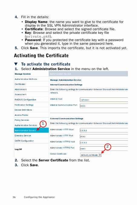
4. Fill in the details:• Display Name: the name you want to give to the certificate for
display in the SSL VPN Administrator interface.• Certificate: Browse and select the signed certificate file.• Key: Browse and select the private certificate key file
(private.pk8).• Password: If you protected the certificate key with a password
when you generated it, type in the same password here.5. Click Save. This imports the certificate, but it is not activated yet.
Activating the Certificate
To activate the certificate1. Select Administration Service in the menu on the left.
2. Select the Server Certificate from the list.3. Click Save.
1
2
36 Configuring the Appliance
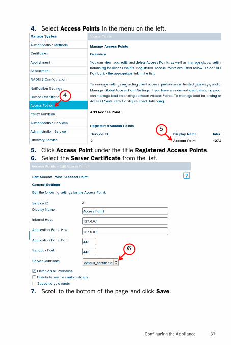
4. Select Access Points in the menu on the left.
5. Click Access Point under the title Registered Access Points.6. Select the Server Certificate from the list.
7. Scroll to the bottom of the page and click Save.
4
5
6
Configuring the Appliance 37
Moving onAfter importing the license and the working certificate, your SSL VPN system is ready to be configured with additional administrator accounts and the user accounts and services that you want the appliance to provide in your network.For step-by-step instructions for tasks outlined below, see the SSL VPN Administrator help system (click the Help link in the top menu of the SSL VPN Administrator) or the SSL VPN Administrator’s Guide.Your next steps with the software include:1. Creating an external user storage.2. Creating user groups and users. Accounts for both administrator
users and end-users are created in the same way. Administrator access can be controlled with access rules based on user groups.
3. Defining access rules for allowing access to the services on the appliance.
4. Defining the services you want to offer.• In addition to other services, you can also configure the SSL VPN
Web Console and the SSL VPN Administrator to be accessible remotely through the Application Portal.
After configuring the administrator accounts, user accounts, and services, you can optionally connect the SSL VPN appliance to the Stonesoft Management Center. This allows you to monitor the appliance status through the Management Client. You can optionally also manage the SSL VPN licenses through the Management Client. In addition, you can configure that SSL VPN logs are sent to the Stonesoft Management Center and can be viewed through the Management Client. See the Stonesoft Administrator’s Guide or the Online Help of the Management Client for more information.
38 Configuring the Appliance
Managing the Appliance
Enabling Command Line AccessYou can enable SSH on the appliance to remotely connect to the operating system command line (Linux) to use standard networking tools (like Ping) or to transfer files through SSH. You can alternatively connect to the engine through a serial cable.If the command line has not been used before, you must first set the command line password.
To enable command line access to the appliance1. Log in to the SSL VPN Web Console remotely through the Access
Point or locally through the management port eth0_0 on the appliance’s back panel at the address https://<Web Console IP Address>:10000.• For detailed instructions for establishing the local connection,
see Logging in to the SSL VPN Web Console (page 23).2. In the SSL VPN Web Console, expand System in the menu on the
left and select Root Password.3. On the right, type in and confirm the command line password for
the account “root”. The “root” account is always the only account for command line access.
4. (Optional) To enable SSH on the appliance, first select Services in the menu on the left, and then select the Enable SSH daemon option under Access Control on the right.
Connecting to Engine Command LineOnce you have enabled command line access (see Enabling Command Line Access above), you can connect to the engine command line.
To connect to engine command line1. Do one of the following:
• Connect the serial cable supplied with the appliance to the serial port on the appliance’s front panel and to a computer, and then open a terminal on the computer using the following settings: 9600 bps, 8 databits, 1 stopbit, no parity.
• Connect to the appliance’s IP address on any interface using an SSH client (for example, PuTTY) on the standard port (TCP/22).
2. Log in with username root and the password you set through the SSL VPN Web Console.
Managing the Appliance 39
• The default key map is set to US English. If you want to change the key map, run the commandsg-reconfigure --no-shutdown.
• The dash character is located to the left of the backspace key in the US English keyboard layout.
Checking System InformationThis section explains how you can check basic system operating status and the software version that the access point is running. The actual SSL VPN services are monitored through the SSL VPN Administrator in the Monitor System pages (see the SSL VPN Administrator’s Guide for details on the SSL VPN services monitoring).
To check the system status and installed software version
1. Log in to the SSL VPN Web Console remotely through the Access Point or locally through the management port eth0_0 on the appliance’s back panel at the address https://<Web Console IP Address>:10000.• For detailed instructions for establishing the local connection,
see Logging in to the SSL VPN Web Console (page 23).2. Information on the software version and system status is
displayed on the right. If you navigate away from this view, you can return by selecting System Information in the menu on the left.
Restarting Services
To restart services1. Log in to the SSL VPN Web Console remotely through the Access
Point or locally through the management port eth0_0 on the appliance’s front panel at the address https://<Web Console IP Address>:10000.• For detailed instructions for establishing the local connection,
see Logging in to the SSL VPN Web Console (page 23).2. Expand System in the menu on the left and select Services.3. On the right, select the services that you wish to restart.4. Click Restart to restart the services that are selected above.
40 Managing the Appliance

Maintenance Operations
Changing the Password for Command Line AccessThe account for the user root is the only account for engine command line access. You can change the password for the root account through the Engine Configuration Wizard following the instructions below or through the SSL VPN Web Console as described in Enabling Command Line Access (page 39).
To change the root password in the Engine Configuration Wizard
1. Connect to the engine command line as described in Connecting to Engine Command Line (page 39).
2. Issue the command sg-reconfigure. The Engine Configuration Wizard starts.
3. Highlight the entry field for Root Password Has Been Set and press ENTER.
4. Enter and confirm the new password in the dialog that opens.5. Highlight Finish and press ENTER.
3
Maintenance Operations 41
Reverting to Previously Installed Software VersionThis procedure allows you to undo a software upgrade. The appliance has two working partitions. One is designated as active and the other as inactive. The inactive partition is used for upgrades and the status is switched between the partitions when the upgrade is ready to be activated. If the appliance does not start up with the new version, it automatically switches to the previous configuration at the next reboot. You can also switch back to the previously installed software version manually as instructed here whenever necessary.
To switch back to the previously active version1. Connect the serial cable supplied with the appliance to the serial
port on the appliance’s front panel and to a computer.2. On the computer, open a terminal with the following settings:
9600 bps, 8 databits, 1 stopbit, no parity.3. (Re)start the appliance:
• If the appliance is powered on, press Enter, log in with username root and the password you set through the SSL VPN Web Console (see Enabling Command Line Access (page 39), and issue command reboot.
4. Wait until a list of the appliance partitions is shown. The currently active partition is highlighted.
5. Select the inactive partition and press Enter. A list of available commands opens.
6. Select Boot SSL-VPN <name of partition> and press Enter. The appliance switches partitions and boots up.
If you want to undo this operation, repeat the steps exactly as above.
Note – When the appliance is powered and you need to unplug it, always wait at least five (5) seconds before plugging in the appliance again. Otherwise, the appliance may not have time to clear properly and fails to start.
42 Maintenance Operations
Resetting the Appliance to Factory Settings
To reset to factory settings1. Connect the serial cable supplied with the appliance to the serial
port on the appliance’s front panel and to a computer.2. On the computer, open a terminal with the following settings:
9600 bps, 8 databits, 1 stopbit, no parity.3. (Re)start the appliance:
• If the appliance is powered on, press Enter, log in with username root and the password you set through the SSL VPN Web Console (see Enabling Command Line Access (page 39), and issue command reboot.
4. Wait until a list of the appliance partitions is shown. The currently active partition is highlighted.
5. Press Enter. A list of available commands opens.6. Select System Restore Options and press Enter.7. Type 1 and press Enter to clear the settings. A confirmation
prompt is shown.8. Type YES and press Enter to perform the reset. If you decide to
cancel the operation, type NO and press Enter.
To use the appliance after a factory reset, you must configure it as explained in Configuring the Appliance (page 20).
Note – Perform a factory reset only if you have a specific need to do so. Consult Stonesoft Support before performing this operation if you are unsure of whether this operation is necessary or not.
Note – When the appliance is powered and you need to unplug it, always wait at least five (5) seconds before plugging in the appliance again. Otherwise, the appliance may not have time to clear properly and fails to start.
Caution – Do not unplug the power from the appliance or interrupt the reset in any way. If the reset is interrupted, the appliance may become unusable until serviced.
Maintenance Operations 43
Replacing the Interface Module
You can replace an interface module either with the same type of module or with a different type of module. You can also replace the interface module with the plate that covered the interface module slot at the time of delivery. See Reattaching the Plate to the Interface Module Slot (page 47).If the number of ports in the old module and the new module are the same, the mapping between the Interface IDs and the port names does not change. No further action is needed after you have replaced the module. However, if the number of ports in the new module is not the same as in the old module, you may need to modify the interface definitions.For more information, see the Interface Module Guide delivered with the interface module.
To replace the interface module1. Connect to the engine command line as described in Connecting
to Engine Command Line (page 39).2. Shut down the engine:
• If the appliance is powered on, press Enter, log in as the user root with the password you have set for the appliance, and issue the command halt.
3. Unplug all power cords from the system and the wall outlets.4. Disconnect all the cables from the appliance.5. (Recommended) Fasten a grounding strap to your wrist so that it
contacts your bare skin and attach the other end of the strap to the appliance.
6. Locate the interface module’s release lever on the left of the module’s front panel.
7. Release the module from its locking position by pressing the lever right and by holding the lever down. Pull the module carefully out of the slot using the handle on the module’s front panel.
Caution – Do not install or remove the interface module if the appliance is powered on to avoid damaging the module and the appliance.
Note – If the unlocked module does not move, keep the release lever down, press the module gently toward the back of the slot, and pull the module again by the handle.
44 Maintenance Operations

8. Replace the module with a new one. See Installing the Interface Module (page 10).
9. Connect the cables and plug the power cords to the system and to the wall outlets.
10. Power on the appliance using the power button.
11. If the number of ports in the new module differs from the old module, modify the interface definitions as necessary in the SSL VPN Web Console and save and activate the changes. See the SSL VPN Administrator’s Guide for more information on modifying interface definitions.
Changing the CFast CardIf necessary, you can replace the CFast card with another CFast card that you have received from Stonesoft.
To change the CFast card1. Power off the appliance.2. Locate the CFast card on the appliance’s back panel. See Back
Panel (page 9).3. Push the CFast card in gently to release the card from its slot.4. Locate the new CFast card and note the two slots at the end of the
card. One of the slots is wider than the other one.5. Turn the CFast card so that the end with the slots is turned toward
the appliance and the wider slot is on the left.6. Insert the new CFast card into the slot and push it in gently to lock
the card into place.
To use the appliance after changing the CFast card, you must configure it as explained in Configuring the Appliance (page 20).
Caution – Do not power on the appliance if you have not installed an interface module or a placeholder module in the appliance.
Caution – Make sure that you insert the CFast card correctly. The wider slot at the end of the card must be on the left when you insert the card.
Maintenance Operations 45
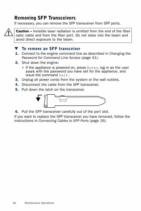
Removing SFP TransceiversIf necessary, you can remove the SFP transceiver from SFP ports.
To remove an SFP transceiver1. Connect to the engine command line as described in Changing the
Password for Command Line Access (page 41).2. Shut down the engine:
• If the appliance is powered on, press Enter, log in as the user root with the password you have set for the appliance, and issue the command halt.
3. Unplug all power cords from the system or the wall outlets.4. Disconnect the cable from the SFP transceiver.5. Pull down the latch on the transceiver.
6. Pull the SFP transceiver carefully out of the port slot.If you want to replace the SFP transceiver you have removed, follow the instructions in Connecting Cables to SFP Ports (page 16).
Caution – Invisible laser radiation is emitted from the end of the fiber-optic cable and from the fiber port. Do not stare into the beam and avoid direct exposure to the beam.
46 Maintenance Operations
Reattaching the Plate to the Interface Module Slot
To reattach the plate to the interface module slot1. Power off the appliance.2. Remove the interface module from the interface module slot. See
Front Panel (page 8).3. Make note of the tab at the lower left corner of the plate.4. Insert the tab into the hole in the lower left corner of the slot
casing.5. Slide the plate inward until it covers the slot and the thumbscrew
in the plate aligns with the screw hole to the right of the slot.6. Tighten the thumbscrew until the plate is attached firmly in place.
Disposal InstructionsDispose of the appliance separately from household waste at an appropriate waste disposal facility at the end of its useful service life.
Caution – Do not power on the appliance if no interface module is installed or if the interface module slot is not covered by the plate that covered the slot at the time of delivery. Using the appliance without an interface module or without the plate covering the interface slot may damage the appliance and will void the warranty.
Disposal Instructions 47

Stonesoft Appliance Installation Guide
This booklet covers the initial installation and configuration tasks
specific to your Stonesoft Appliance.
For information on how to prepare the Management Center for a new
engine installation, see the other available documentation. See inside
for further details.
All documentation and our technical knowledge base is available at:
www.stonesoft.com/support.
Copyright 2013 Stonesoft Corporation.
Stonesoft Inc.Americas Headquarters1050 Crown Pointe ParkwaySuite 900Atlanta, GA 30338, USAtel. +1 866 869 4075fax. +1 770 668 1131
Stonesoft CorporationInternational Headquarters
Itälahdenkatu 22 AFl-0021O Helsinki, Finland
tel. +358 9 4767 11fax. +358 9 4767 1349
www.stonesoft.com