Embed Size (px)
Citation preview
Stonesoft NextGeneration FirewallHardware GuideModels 105, 110, 115, and 315Revision E
2
Table of contents1 Appliance features............................................................................................................................................... 3
Model 105 features........................................................................................................................................ 3Model 110 features........................................................................................................................................ 5Model 115 features........................................................................................................................................ 7Model 315 features........................................................................................................................................ 9
2 Precautions......................................................................................................................................................... 12Safety precautions........................................................................................................................................12Electrical safety precautions........................................................................................................................ 12
3 Install the appliance.......................................................................................................................................... 13Install a 3G modem in the appliance.......................................................................................................... 13Mount a 105 appliance................................................................................................................................ 15Mount a 110 or 115 appliance.................................................................................................................... 16Install a 315 appliance in a rack................................................................................................................. 16Connect antennas and cables..................................................................................................................... 17Default port settings for plug-and-play........................................................................................................ 19How the integrated switch works.................................................................................................................19
4 Compliance information.................................................................................................................................... 21Applied technologies...................................................................................................................................21National restrictions and requirements for authorization............................................................................. 21
5 Find product documentation............................................................................................................................ 22
Appliance features | 3
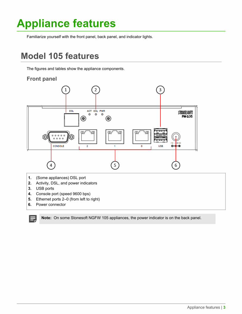
Appliance featuresFamiliarize yourself with the front panel, back panel, and indicator lights.
Model 105 featuresThe figures and tables show the appliance components.
Front panel
1. (Some appliances) DSL port2. Activity, DSL, and power indicators3. USB ports4. Console port (speed 9600 bps)5. Ethernet ports 2–0 (from left to right)6. Power connector
Note: On some Stonesoft NGFW 105 appliances, the power indicator is on the back panel.
Appliance features | 4
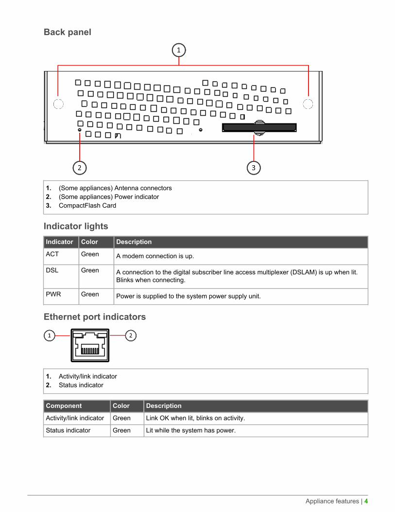
Back panel
1. (Some appliances) Antenna connectors2. (Some appliances) Power indicator3. CompactFlash Card
Indicator lightsIndicator Color Description
ACT Green A modem connection is up.
DSL Green A connection to the digital subscriber line access multiplexer (DSLAM) is up when lit.Blinks when connecting.
PWR Green Power is supplied to the system power supply unit.
Ethernet port indicators
1. Activity/link indicator2. Status indicator
Component Color Description
Activity/link indicator Green Link OK when lit, blinks on activity.
Status indicator Green Lit while the system has power.
Appliance features | 5
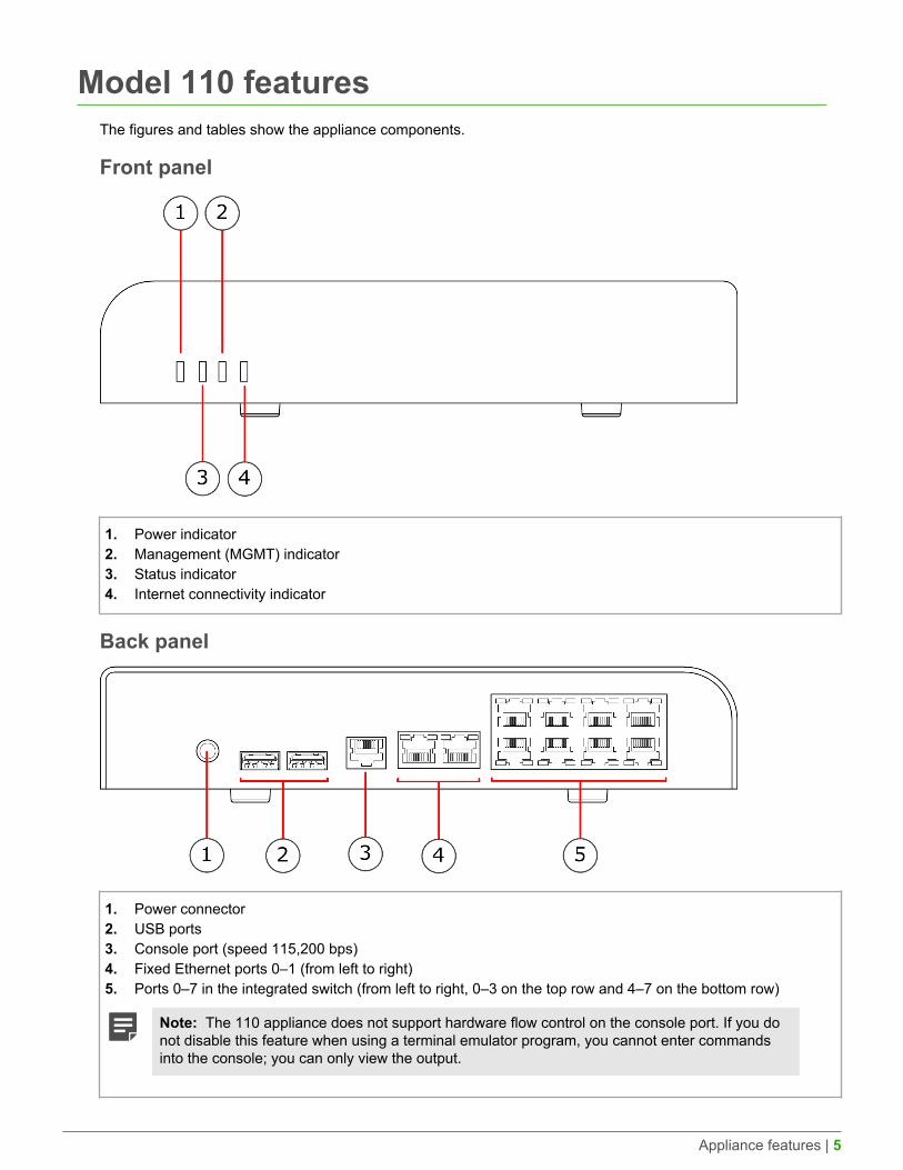
Model 110 featuresThe figures and tables show the appliance components.
Front panel
1. Power indicator2. Management (MGMT) indicator3. Status indicator4. Internet connectivity indicator
Back panel
1. Power connector2. USB ports3. Console port (speed 115,200 bps)4. Fixed Ethernet ports 0–1 (from left to right)5. Ports 0–7 in the integrated switch (from left to right, 0–3 on the top row and 4–7 on the bottom row)
Note: The 110 appliance does not support hardware flow control on the console port. If you donot disable this feature when using a terminal emulator program, you cannot enter commandsinto the console; you can only view the output.
Appliance features | 6
Indicator lightsIndicator Color Description
Power Green Power is supplied to the system power supply unit.
Amber Initial contact is established but the engine is not online. Blinks until initial contact isestablished.
Status
Green The engine is online.
MGMT Green Management connection is established.
Internet Green Internet connection is up.
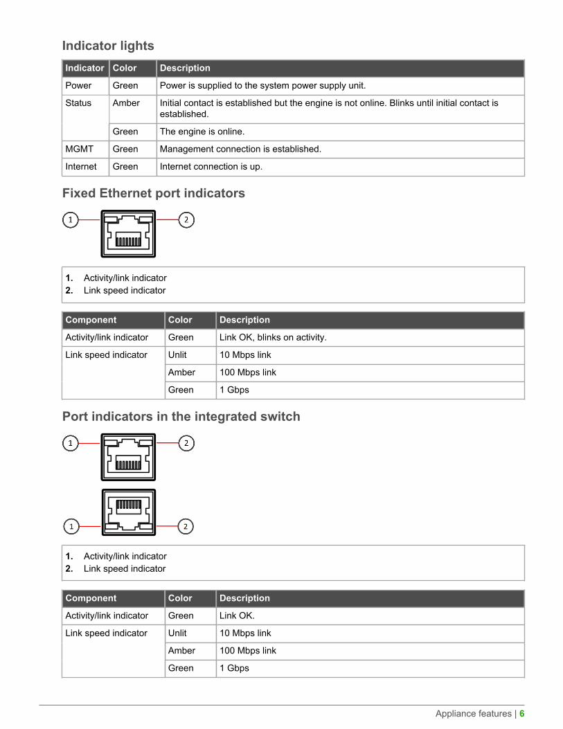
Fixed Ethernet port indicators
1. Activity/link indicator2. Link speed indicator
Component Color Description
Activity/link indicator Green Link OK, blinks on activity.
Unlit 10 Mbps link
Amber 100 Mbps link
Link speed indicator
Green 1 Gbps
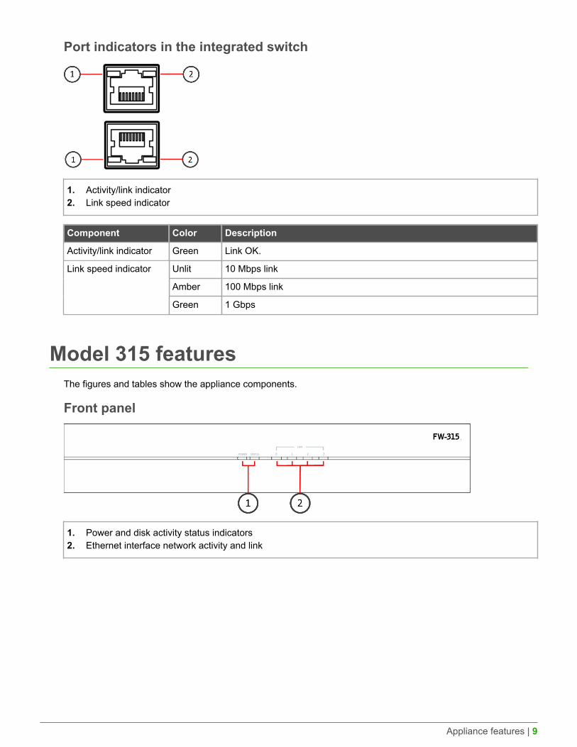
Port indicators in the integrated switch
1. Activity/link indicator2. Link speed indicator
Component Color Description
Activity/link indicator Green Link OK.
Unlit 10 Mbps link
Amber 100 Mbps link
Link speed indicator
Green 1 Gbps
Appliance features | 7
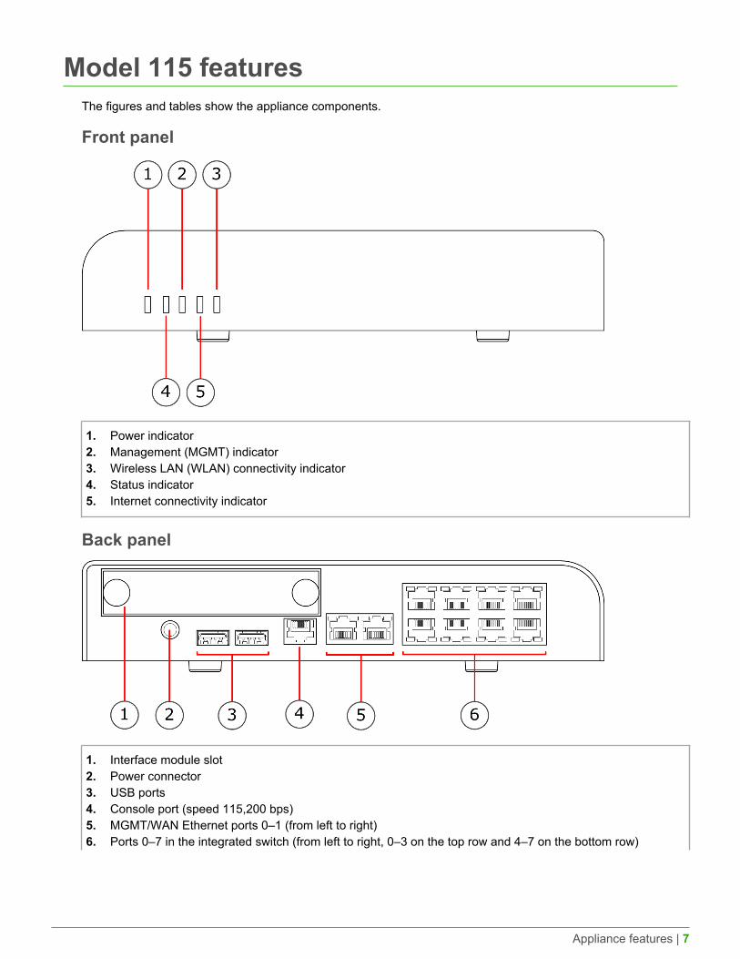
Model 115 featuresThe figures and tables show the appliance components.
Front panel
1. Power indicator2. Management (MGMT) indicator3. Wireless LAN (WLAN) connectivity indicator4. Status indicator5. Internet connectivity indicator
Back panel
1. Interface module slot2. Power connector3. USB ports4. Console port (speed 115,200 bps)5. MGMT/WAN Ethernet ports 0–1 (from left to right)6. Ports 0–7 in the integrated switch (from left to right, 0–3 on the top row and 4–7 on the bottom row)
Appliance features | 8
Note: The 115 appliance does not support hardware flow control on the console port. If you donot disable this feature when using a terminal emulator program, you cannot enter commandsinto the console; you can only view the output.
Ethernet port namesEthernet port names are based on the slot and port numbers. The first number in the name represents the slot onthe appliance. The second number represents the port on the slot. Example: eth2_0 is located on port 0 of slot 2.
Component Slot number Slot location Port numbers
Fixed Ethernet ports 0 Back panel eth0_0 and eth0_1.
Interface modules 1 Back panel The port numbers startfrom 0 and increase fromleft to right.
Example: The port farthestto the left in slot 1 iseth1_0.
Indicator lightsIndicator Color Description
Power Green Power is supplied to the system power supply unit.
Amber Initial contact is established but the engine is not online. Blinks until initial contact isestablished.
Status
Green The engine is online.
MGMT Green Management connection is established.
Internet Green Internet connection is up.
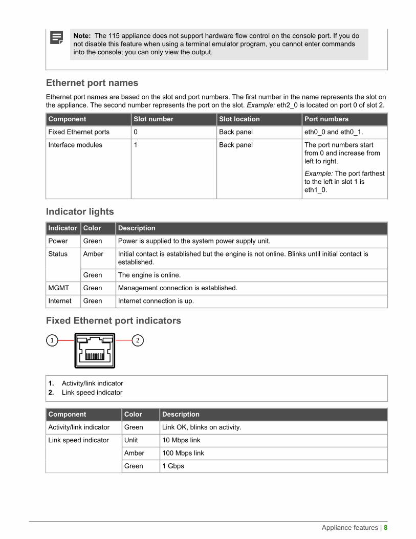
Fixed Ethernet port indicators
1. Activity/link indicator2. Link speed indicator
Component Color Description
Activity/link indicator Green Link OK, blinks on activity.
Unlit 10 Mbps link
Amber 100 Mbps link
Link speed indicator
Green 1 Gbps
Appliance features | 9
Port indicators in the integrated switch
1. Activity/link indicator2. Link speed indicator
Component Color Description
Activity/link indicator Green Link OK.
Unlit 10 Mbps link
Amber 100 Mbps link
Link speed indicator
Green 1 Gbps
Model 315 featuresThe figures and tables show the appliance components.
Front panel
1. Power and disk activity status indicators2. Ethernet interface network activity and link
Appliance features | 10
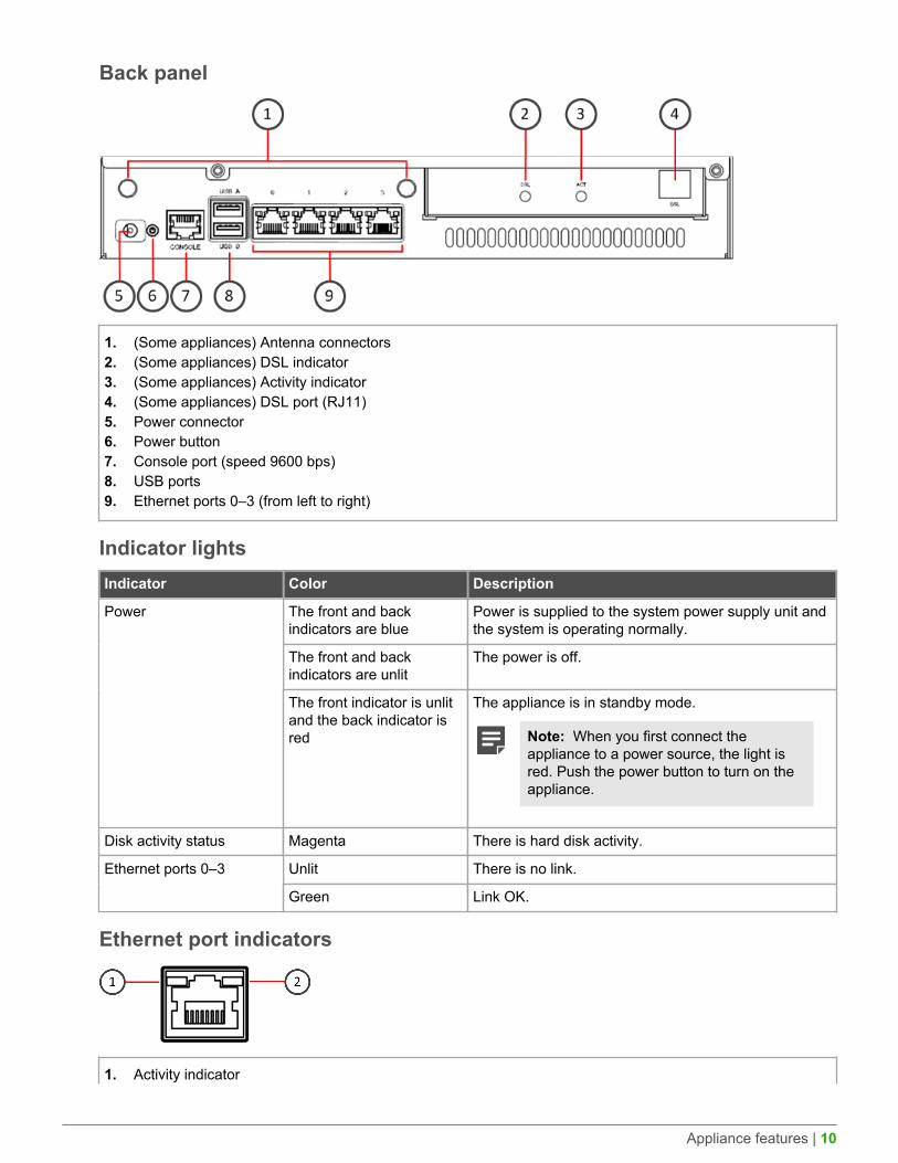
Back panel
1. (Some appliances) Antenna connectors2. (Some appliances) DSL indicator3. (Some appliances) Activity indicator4. (Some appliances) DSL port (RJ11)5. Power connector6. Power button7. Console port (speed 9600 bps)8. USB ports9. Ethernet ports 0–3 (from left to right)
Indicator lightsIndicator Color Description
The front and backindicators are blue
Power is supplied to the system power supply unit andthe system is operating normally.
The front and backindicators are unlit
The power is off.
Power
The front indicator is unlitand the back indicator isred
The appliance is in standby mode.
Note: When you first connect theappliance to a power source, the light isred. Push the power button to turn on theappliance.
Disk activity status Magenta There is hard disk activity.
Unlit There is no link.Ethernet ports 0–3
Green Link OK.
Ethernet port indicators
1. Activity indicator
Appliance features | 11
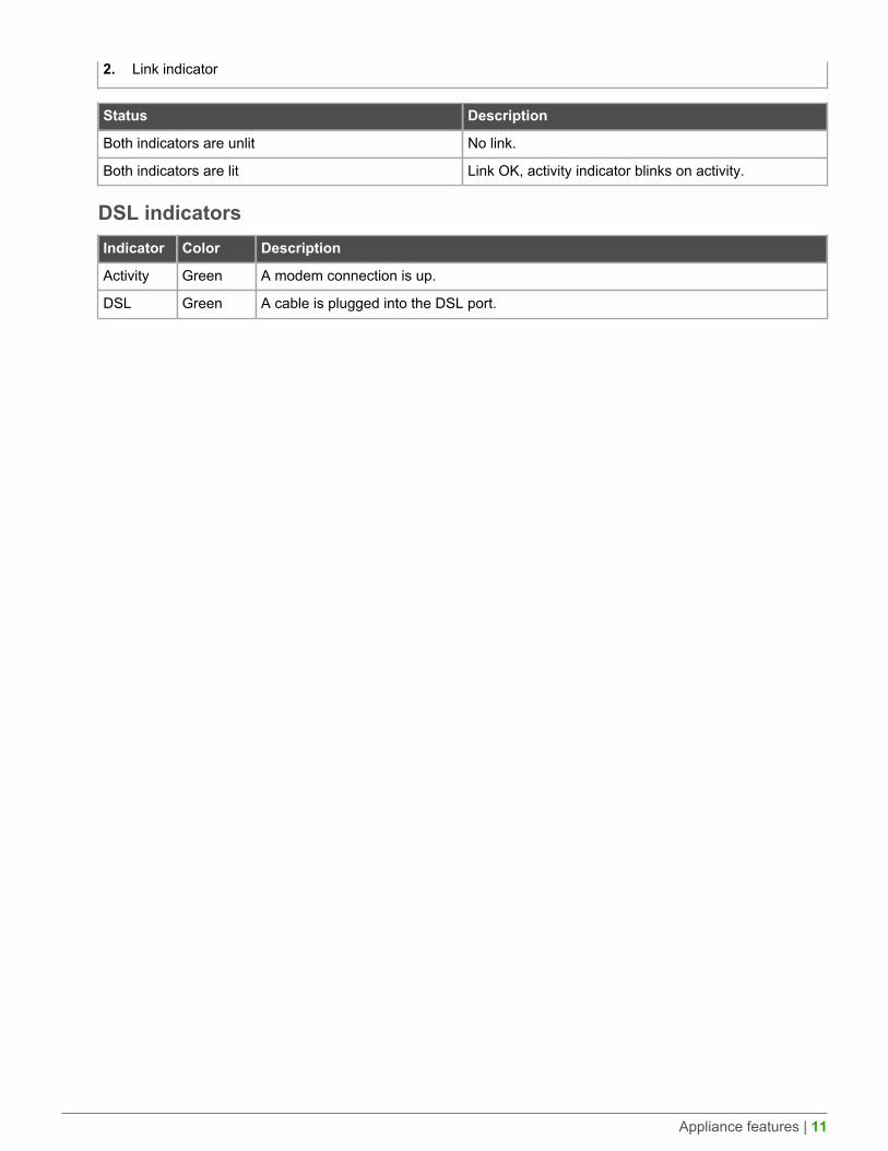
2. Link indicator
Status Description
Both indicators are unlit No link.
Both indicators are lit Link OK, activity indicator blinks on activity.
DSL indicatorsIndicator Color Description
Activity Green A modem connection is up.
DSL Green A cable is plugged into the DSL port.
Precautions | 12
PrecautionsThe precautions provide safety guidance when working with Forcepoint appliances and electrical equipment.
Safety precautionsRead the safety information and follow the procedures whenever you are working with electronic equipment.
CAUTION: Forcepoint appliances cannot be serviced by end users. Never open the appliancecovers for any reason. Doing so can lead to serious injury and void the hardware warranty.
General safetyFollow these rules to ensure general safety.
• Keep the area around the appliance clean and free of clutter.• Use a regulating uninterruptible power supply (UPS) to keep your system operating if there is a power failure
and to protect the appliance from power surges and voltage spikes.• If you need to switch off or unplug the appliance, always wait at least five seconds before turning on or
plugging in the appliance again.
Operating precautions• Power supplies — Do not open the power supply casing. Only the manufacturer's qualified technician can
access and service power supplies.• WLAN precautions — Data traffic by a wireless connection might allow unauthorized third parties to receive
data. Take the necessary steps to secure your radio network. See http://www.wi-fi.org for information aboutsecuring your WLAN.
Restrictions and requirements might apply for authorizing wireless devices. Check with your local authoritiesfor additional information.
Electrical safety precautionsFollow basic electrical safety precautions to protect yourself from harm and the appliance from damage.
• Know the locations of the power on/off button and the emergency turn-off switch, disconnection switch, orelectrical outlet for the room. If an electrical accident occurs, you can quickly turn off power to the system.
• When working with high-voltage components, do not work alone.• When working with electrical equipment that is turned on, use only one hand. This is to avoid making a
complete circuit, which causes an electric shock. Use extreme caution when using metal tools, which caneasily damage any electrical components or circuit boards the tools come into contact with.
• Do not use mats designed to decrease electrostatic discharge as protection from electric shock. Instead, userubber mats that have been designed as electrical insulators.
• 315 appliances only: The power supply cable must include a grounding plug and must be plugged into agrounded electrical outlet.
Install the appliance | 13
Install the appliancePrepare and install the appliance in your network.
• You have installed a Stonesoft Management Center (SMC) on a separate server.• You have configured the Firewall element in the Management Client, and saved the initial configuration on a
USB drive.
Note: For additional information on SMC installation and initial configuration, see the StonesoftNext Generation Firewall Installation Guide.
• You have inspected the appliance, the delivery box, and all components included in the shipment.
Note: Do not use damaged appliances or components.
Install a 3G modem in the applianceInstall a SIM card into a 3G modem, connect the external antenna, and connect the modem to the appliance.
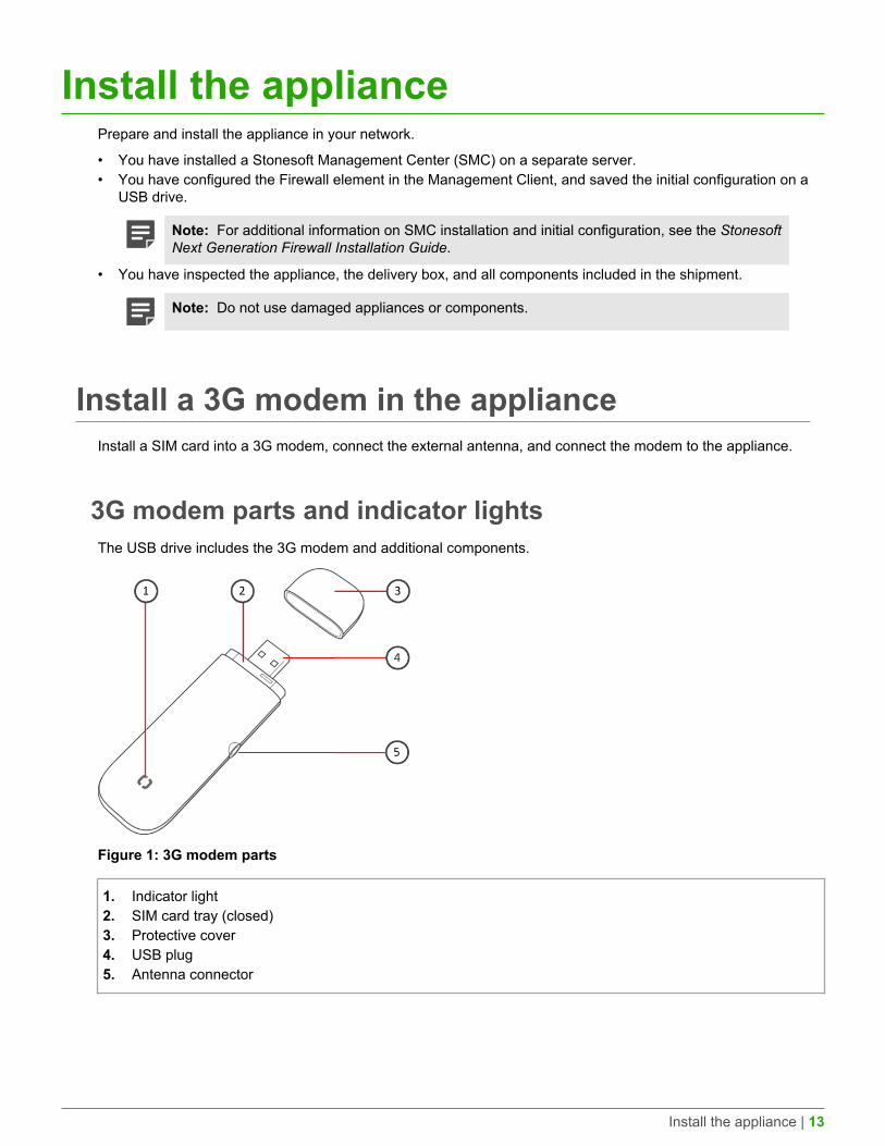
3G modem parts and indicator lightsThe USB drive includes the 3G modem and additional components.
Figure 1: 3G modem parts
1. Indicator light2. SIM card tray (closed)3. Protective cover4. USB plug5. Antenna connector
Install the appliance | 14
Table 1: 3G modem indicator lights
Indicator status Color Description
Quickly flashing light Alternating colors (red, yellow,green, blue, and purple)
Indicates that the modem issearching for a network.
Slowly flashing light Red Indicates a problem with the SIMcard or that there is no network.
Any color Indicates that the modem has founda network.
Blue Transfer rate is UMTS.
Green Transfer rate is HSPA+/ HSPA.
Purple Transfer rate is EDGE.
Light continuously on
Yellow Transfer rate is GPRS.
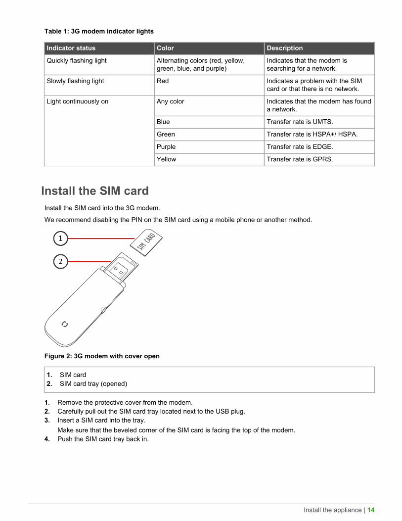
Install the SIM cardInstall the SIM card into the 3G modem.
We recommend disabling the PIN on the SIM card using a mobile phone or another method.
Figure 2: 3G modem with cover open
1. SIM card2. SIM card tray (opened)
1. Remove the protective cover from the modem.2. Carefully pull out the SIM card tray located next to the USB plug.3. Insert a SIM card into the tray.
Make sure that the beveled corner of the SIM card is facing the top of the modem.4. Push the SIM card tray back in.
Install the appliance | 15
Connect the external antennaUse the external antenna with the modem for optimal speed and performance.
1. Open the protective cover of the antenna connector at the side of the modem, and pull out the cover slightly.2. Insert the antenna cable firmly to the antenna connector.3. Attach the antenna to the wall with the two self-adhesive fastening strips included in the shipment.
1. Attach one strip to the surface of the antenna and the other strip to the wall surface.2. Position the antenna so the transmission level is optimal; for example, near a window that faces the
direction of a base station.
Connect the 3G modem to an applianceInsert the modem in a USB port on the appliance.
Important: For safety reasons, we recommend using the USB extension cable when you connectthe 3G modem to an appliance.
1. Attach the USB extension cable to the USB plug of the modem.2. Connect the USB extension cable to a USB port on the appliance.
Change the 3G modem SIM cardIf necessary, replace the SIM card and update the interface information.
We recommend that you use a mobile phone or other method to disable the PIN on the SIM card beforeinstallation.
1. Disconnect the modem USB extension cable from the USB port on the appliance.2. Carefully pull out the SIM card tray.3. Remove the existing SIM card from the tray.4. Insert the new SIM card into the tray.5. Push the SIM card tray back in.6. Attach the USB extension cable to the modem and to the USB port on the appliance.7. Using the Management Client, modify the interface details according to your service provider's instructions.8. Refresh the engine policy in the Management Client to transfer the configuration changes.
Mount a 105 applianceYou can mount a 105 appliance to a wall or place the appliance on a horizontal surface such as a desk or rackshelf.
The bracket and screws are not included by default. You can order them separately.
Note: Use the appropriate screws for the surface you are mounting the appliance on. Make surethat the screws are long enough to provide sufficient support for the appliance.
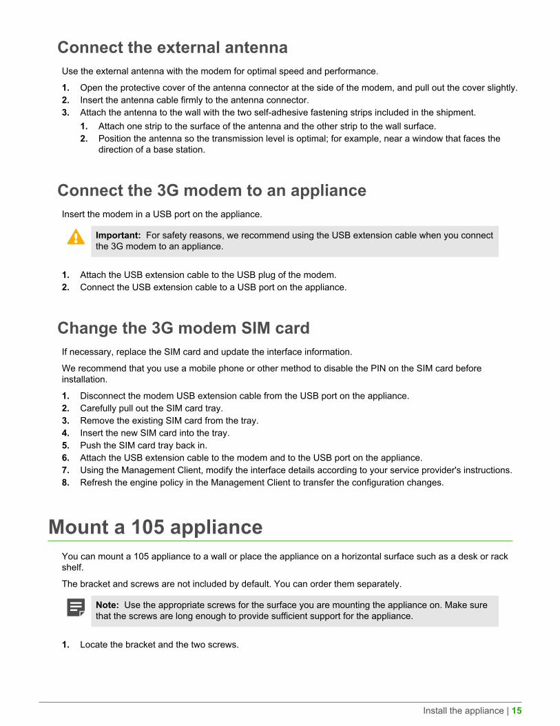
1. Locate the bracket and the two screws.
Install the appliance | 16
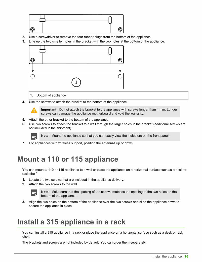
2. Use a screwdriver to remove the four rubber plugs from the bottom of the appliance.3. Line up the two smaller holes in the bracket with the two holes at the bottom of the appliance.
1. Bottom of appliance
4. Use the screws to attach the bracket to the bottom of the appliance.
Important: Do not attach the bracket to the appliance with screws longer than 4 mm. Longerscrews can damage the appliance motherboard and void the warranty.
5. Attach the other bracket to the bottom of the appliance.6. Use two screws to attach the bracket to a wall through the larger holes in the bracket (additional screws are
not included in the shipment).
Note: Mount the appliance so that you can easily view the indicators on the front panel.
7. For appliances with wireless support, position the antennas up or down.
Mount a 110 or 115 applianceYou can mount a 110 or 115 appliance to a wall or place the appliance on a horizontal surface such as a desk orrack shelf.
1. Locate the two screws that are included in the appliance delivery.2. Attach the two screws to the wall.
Note: Make sure that the spacing of the screws matches the spacing of the two holes on thebottom of the appliance.
3. Align the two holes on the bottom of the appliance over the two screws and slide the appliance down tosecure the appliance in place.
Install a 315 appliance in a rackYou can install a 315 appliance in a rack or place the appliance on a horizontal surface such as a desk or rackshelf.
The brackets and screws are not included by default. You can order them separately.
Install the appliance | 17
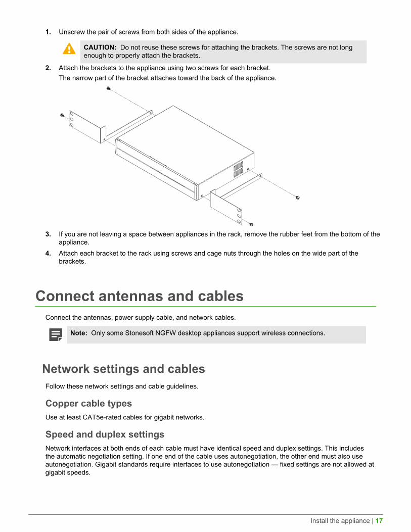
1. Unscrew the pair of screws from both sides of the appliance.
CAUTION: Do not reuse these screws for attaching the brackets. The screws are not longenough to properly attach the brackets.
2. Attach the brackets to the appliance using two screws for each bracket.The narrow part of the bracket attaches toward the back of the appliance.
3. If you are not leaving a space between appliances in the rack, remove the rubber feet from the bottom of theappliance.
4. Attach each bracket to the rack using screws and cage nuts through the holes on the wide part of thebrackets.
Connect antennas and cablesConnect the antennas, power supply cable, and network cables.
Note: Only some Stonesoft NGFW desktop appliances support wireless connections.
Network settings and cablesFollow these network settings and cable guidelines.
Copper cable typesUse at least CAT5e-rated cables for gigabit networks.
Speed and duplex settingsNetwork interfaces at both ends of each cable must have identical speed and duplex settings. This includesthe automatic negotiation setting. If one end of the cable uses autonegotiation, the other end must also useautonegotiation. Gigabit standards require interfaces to use autonegotiation — fixed settings are not allowed atgigabit speeds.
Install the appliance | 18
Connect the antennasIf your appliance has WLAN support, connect the antennas.
1. Install the antennas to the two connectors on the back panel of the appliance.2. Tighten the knurled nuts at the base of the antennas to secure them firmly to the appliance.3. Position the antennas.
Connect network cablesEthernet ports are mapped to interface IDs during the initial configuration. Determine which Ethernet ports to usefor connecting to your networks.
Note: In appliances that have WLAN support, the port number of the integrated wireless networkcard is 3 for 105 appliances, 1 for 115 appliances, and 5 for 315 appliances.
Note: In the 110 and 115 appliances, the ID of the integrated switch is 0.
1. Connect network cables to the Ethernet ports.If you use the plug-and-play method, connect a cable to Ethernet port 0 for contacting the Installation Server.
• 105 appliances — The ports are numbered 2–0 from left to right.• 110 appliances — The ports are numbered 0–1 from left to right.• 115 appliances — The ports are numbered 0–1 from left to right.
Note: Port 0 is the MGMT port, and port 1 is the WLAN port.
• 315 appliances — The ports are numbered 0–3 from left to right.2. If the appliance has DSL support, connect the cable to the RJ11 DSL port.
The DSL port number is 4.
CAUTION: To reduce the risk of fire, use only a 26 AWG or larger (for example, 24 AWG) ULListed or CSA Certified Telecommunication Line Cord.
3. If the appliance has an integrated switch, connect the cables to the ports in the integrated switch.The ID of the integrated switch is 0. The ports are numbered from left to right: 0–3 on the top row and 0–1 onthe bottom row.
4. (Optional) Connect a 3G modem to one of the USB ports.The port number of the 3G modem is 0.
Connect the power supplyUse the power cable to plug in the appliance.
Note: We recommend using a UPS to ensure continuous operation and minimize the risk ofdamage to the appliance in case of sudden loss of power.
Note: Standby power is supplied to the system even when the appliance is turned off.
1. Connect the power cable to the power connector.
Install the appliance | 19
• 105 appliances — The power connector is on the front of the appliance.• 110 and 115 appliances — The power connector is on the back of the appliance.• 315 appliances — The power connector is on the back of the appliance.
2. Plug the power cable into a grounded, high-quality power strip that offers protection from electrical noise andpower surges.
Default port settings for plug-and-playThe appliance uses the default port settings when contacting the Installation Server using the plug-and-playmethod.
Different ports are available to contact the Installation Server. Make sure the port settings are configured correctlyin the Management Client for the initial configuration. If one method fails, the appliance uses the next port.
Table 2: Plug-and-play port order and settings
Order Port type Default settings
1 3G modem port • Access Point Name — internet• Phone number — *99#• PIN Code — <Empty value>
Note: You must disable the PIN on the modem.
2 ADSL port Set the ADSL Service Provider to Automatic in the initial configuration.
For a list of the predefined ADSL settings, see Knowledge Base article 9742.
3 Ethernet port 0 The corresponding interface in the initial configuration must have a dynamic IPv4address.
How the integrated switch worksThe integrated switch of the 110 and 115 appliances enable you to configure port groups. The Stonesoft NGFWengine does not inspect traffic between ports in the same port group.
Note: You can only use the integrated switch if the appliance has been configured as a SingleFirewall. You cannot use the integrated switch as an external switch device without StonesoftNGFW properly configured and running. Only the 110 or 115 appliance can use the integratedswitch.
When the Stonesoft NGFW engine is in the initial configuration state and no configuration has been saved to theintegrated switch, ports in the integrated switch are not configured into port groups and the integrated switch doesnot yet route traffic. After a configuration has been saved, traffic is allowed between ports in the same port groupaccording to the configuration even if you reboot the appliance.
If you turn off the appliance, the port group configuration is reset and traffic between the ports in the same portgroup is interrupted. The last saved port group configuration is automatically applied to the appliance when theappliance has been turned on again.

Install the appliance | 20
Note: The ports in the integrated switch of the 110 and 115 appliances do not support VLANtagging.
Compliance information | 21
Compliance informationStonesoft NGFW appliances that have wireless support are in compliance with the EMC directive (2014/30/EU)and the FCC standard (FCC Part 15) for wireless devices intended for home and office use.
This information is valid for all dual band products (2.4 GHz, IEEE 802.11b/g/n, and 5 GHz, IEEE 802.11n).
The supported channels and frequencies for Stonesoft NGFW appliances are listed by country in theManagement Client. The wireless configuration is transferred to the appliance when you install the policy on theengine.
Applied technologiesThe appliance uses these technologies.
• Radio spectrum — Sub-bands 2400–2483,5 MHz, 5150–5250 MHz, 5250–5350 MHz, and 5470–5725 MHz• Safety — Dual band products• Electromagnetic Compatibility (EMC) — Dual band products
National restrictions and requirements forauthorization
These appliances can be operated within FCC DFS2 band or ETSI/EC DFS band, or other countries that regulateor plan to regulate mid-5 GHz band.
The usage of mid-5 GHz band is subject to the regulatory approval alone with the resided devices.
The requirements for any country or area might change. We recommend that you check with your localauthorities for the latest status of national requirements for 2.4 GHz and 5 GHz wireless LANs.

Find product documentation | 22
Find product documentationOn the Forcepoint support website, you can find information about a released product, including productdocumentation, technical articles, and more.
You can get additional information and support for your product on the Forcepoint support website at https://support.forcepoint.com. There, you can access product documentation, Knowledge Base articles, downloads,cases, and contact information.
Copyright © 1996 - 2016 Forcepoint LLC Forcepoint™ is a trademark of Forcepoint LLC.
SureView®, ThreatSeeker®, TRITON®, Sidewinder® and Stonesoft® are registered trademarks of Forcepoint LLC. Raytheon is a registered trademark of Raytheon Company.
All other trademarks and registered trademarks are property of their respective owners.