Embed Size (px)
Citation preview
SECTION 1 TROUBLESHOOTING
STEERING PROBLEMS
PROBLEM
Hard Steering
CAUSE
Low Tire Pressure
Lack of Lubricant
Bearings and/or Bushings worn
Tie Rods Bent
Steering Gear Broken
MOWER PAN AND BLADE PROBLEMS
PROBLEM CAUSE
Blade Won't Turn Belt Off Pulleys
Belt Damaged
Blade Nut Loose
Blade Won't Disengage
Blade Leaves Swirl Marks in Lawn
REMEDY
Check Pressure Chapter I1 Section 1
Lubricate Chapter I1 Section 1
Steering Disassembly and Inspection Chapter I1 Section 2
Straighten or Replace Chapter I1 Section 2
Disassembly and Replacement Chapter I1 Section 2
Blade Brake Not Working
Pan Unlevel
Blade Unlevel or Bent
REMEDY
Replace Chapter I1 Section 3
Replace Chapter I1 Section 3
Tighten Chapter 11 Section 1 Refer to Spec. Sheet -- Torque
Check Blade Brake Tension Chapter I1 Section 3
Correct Pan Level Chapter I1 Section 3
Correct Pan Level Chapter I1 Section 3
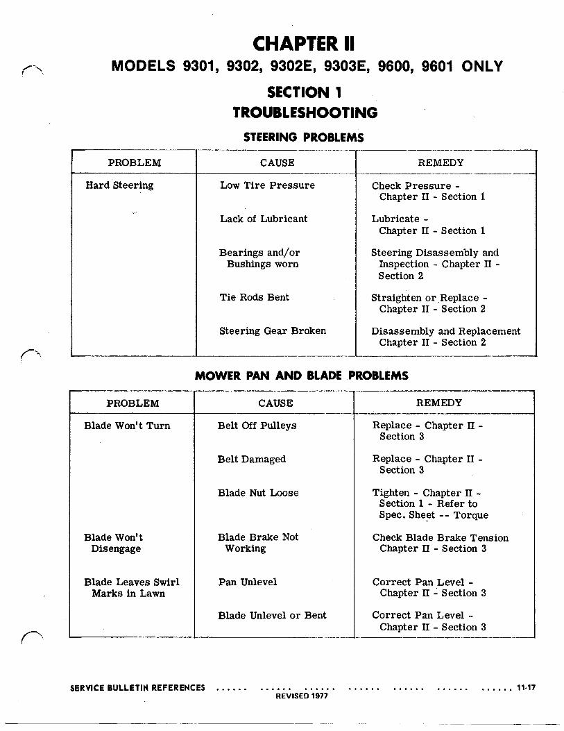
MODELS 9301, 9302, 9302E, 9303E, 9600, 9601 ONLY
MOWER .PAN AND BLADE Cont.
PROBLEM
Belt Comes Off (Rear)
Belt Comes Off (Front)
CAUSE
Belt Keeper Loose
Broken Belt
*Top Idler Pulley Broken or Bent
*Intermediate Shaft Loose
Rear Idler Spring Broken
Rear Idler Arm Broken
Broken Belt
*Bottom Idler Pulley Broken or Bent
*Intermediate Shaft Loose
Idler Arm Broken or Bent
Belt Pulley Bent or Broken
REMEDY
Tighten Chapter I1 Section 3
Replace Chapter I1 Section 3
Replace Chapter I1 Section 3
Tighten Chapter I1 Section 3
Replace Chapter I1 Section 3
Replace Chapter I1 Section 3
Replace Chapter I1 Section 3
Replace Chapter 11 Section 3
Tighten Chapter I1 Section 3
Replace Chapter I1 Section 3
Replace Chapter I1 Section 3
*Diagram shown only.
DRIVE PROBLEMS'
I PROBLEM
Mower Will Not Propel
CAUSE
Improper drive adjust- ment
Drive Disc Polished
Drive Disc Broken
REMEDY
Adjust Chapter I1 Section 4
Score Chapter I1 Section 4
Repair o r Replace, Chapter I1 Section 4
11-18 SERVICEBULLETINREFERENCES REVISED 1977
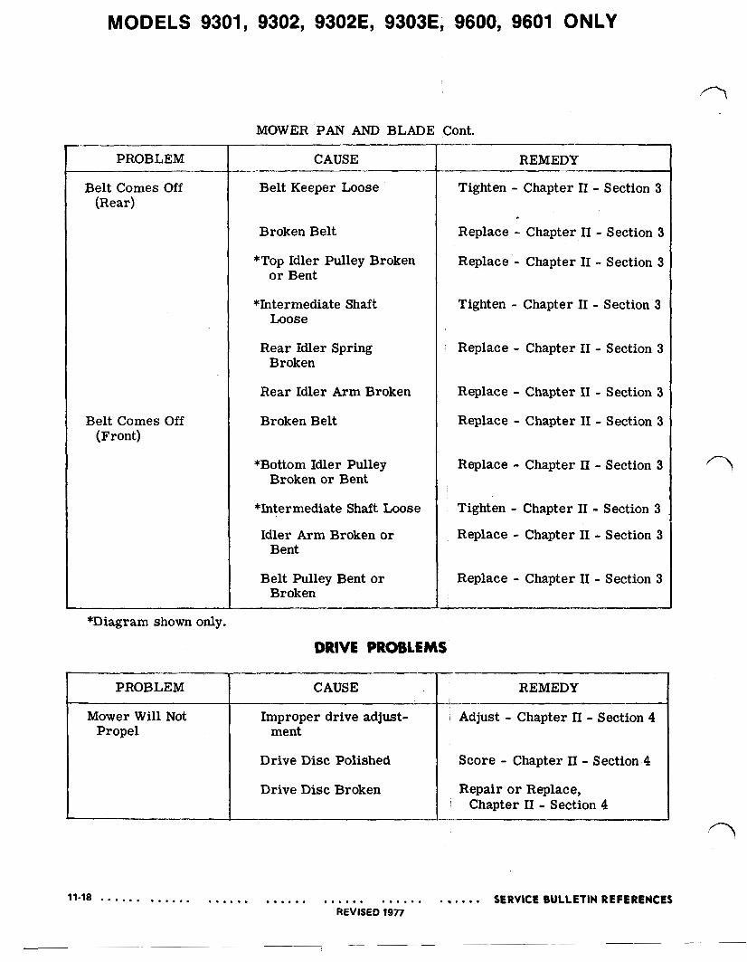
MODELS 9301, 9302, 9302E, 9303E, 9600, 9601 ONLY
PROBLEM
Mower Will Not Propel Cont.
DRIVE PROBLEMS Cont.
CAUSE
Rubber Drive Roller Worn o r Damaged
Chain Loose
Chain Broken
Transmission Rod(s) Bent
Differential Broken
Sprocket Worn or Broken
Wil l Not Drive In Reverse
Clutch Pedal Must Be Pulled Back for More Drive
REMEDY
Replace Chapter I1 Section 4
Adjust Chapter I1 Section 4
Repair o r Replace, Chapter I1 Section 4
Repair o r Replace, Chapter I1 Section 4
Repair o r Replace, Chapter I1 Section 4
Replace Chapter I1 Section 4
Check Reverse Booster Spring o r Disc. Compression Spring Chapter II Section 4
Disc Compression Spring Adjust Chapter II Section 4
The following check list will assist in locating the problem source.
FUEL PROBLEMS
FUEL TROUBLE SHOOTING
TROUBLES REMEDIES CAUSES
Engine will not start a. Fill tank a. Fuel tank empty
b. Water in fuel b. Drain fuel from tank and
fresh fuel carburetor and replace with
c. Old fuel in tank forms
d. Shut-off valve closed
clean out fuel line gum to plug up fuel line c. Empty out old fuel and
d. Open valve

MODELS 9301, 9302, 9302E, 9303E, '9600, 9601 ONLY
FUEL PROBLEMS Cont. ~-
TROUBLES REMEDIES CAUSES
Engine slows down a. Unplug hole a. Vent hole in fuel tank and stops cap plugged
b. Fuel line or strainer
c. Refill tank c. Fuel tank runs dry
strainer clogged i b. Clean out fuel line or
IGNITION PROBLEMS
SPARK PLUG TROUBLE CHART
PLUG CONDITION
Black carbon or sooty deposit
Pitted o r burned points, white, light tan or blistered de- posits. Rapid wear of points
Cracked or broken Plug
Cracked or broken insulator on lower end of plug
Widening of gap
CAUSES
a. Breaker points dirty or out of adjustment
b. Weak condenser
c. Incorrect plug
a. Incorrect plug
a. Careless installation of Plug
a. Center electrode strained when regapping Plug
a. Normal wear
RECOMMENDATION
a. Clean and adjust gap
b. Check and replace if weak
C. Install correct plug
a. Install correct plug
I-
a. Replace plug
a. Replace plug
a. Clean and regap

MODELS 9301, 9302, 9302E, 9303E, 9600, 9601 ONLY
SPECIFICATIONS
LUBRICATION SPECIFICATIONS Grease For Front Axle & King Pin Spindle Boy “A” Grease or
Multiple Purpose, Automotive Grease
Multiple purpoSe, Automotive Grease Differential Lawn-Boy “A” Grease or
Multiple purpoSe, Automotive Grease
Front Wheel Bearings Lawn-Boy “A” Grease or
Hexshaft Drive Roller #30 Weight Oil
BOLT AND N U T TORQUES
King Pin to Tie Rod Nuts 135 inch pounds Steering Casting Bolts. 135 inch pounds
Engine Mounting Bolts. 135 inch pounds Engine Pulley Bolt 250 inch pounds Drive Disc Screws 90 inch pounds Belt Pulley Nut. 250 inch pounds Blade Nut 600 inch pounds Drive Roller Nuts 90 inch pounds
Wheel Bearing Bolts 175 inch pounds Differential Bolts 135 inch pounds Wheel Nuts Adjustable
Steering Gear Set Screw 135 inch pounds
Hexshaft Bearing Retainer Plate Screws 35 inch pounds
ENGINE SPECIFICATIONS
26” 30”
Idle r.p.m. 1,750 1,750 Operating r.p.m. 3,650 3,650 Oil Requirements SAE 10W/30 SAE 10W/30 Gas Tank Capacity 2 Qt. 2 Qt. Spark Plugs #‘s Champion CJ-8 Champion CJ-8
or Autolite A7N or Autolite A7N
SERVICE BULLETIN REFERENCES 11-21 REVISED 1977
MODELS 9301, 9302, 9302E, 9303E, ;9600, 9601 ONLY
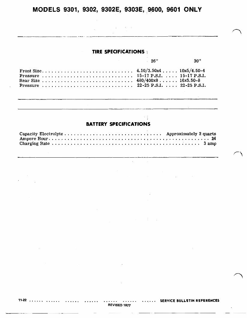
TIRE SPECIFICATIONS
Front Size. 4.10/3.50~4 10x5/4.50-4 Pressure 15-17 P.S.I. 15-17 P.S.I. Rear Size 480/400x8 16~5.50-8 Pressure 22-25 P.S.I. 22-25 P.S.I.
BATTERY SPECIFICATIONS
Capacity Electrolyte Approximately 2 quarts Ampere Hour 24 Charging Rate 3 amp
SERVICE BULLETIN REFERENCES REVISED 1977

MODELS 9301, 9302, 9302E, 9303E, 9600, 9601 ONLY
SECTION 2
HOW TO REPAIR AND REPLACE
STEERING To insure trouble-free operation, use a grease gun and apply a good quality automotive chassis lubricant to the five zerk fittings. (Figure 2-1). Or Lawn-Boy “A” grease.
A positive type steering system is employed. The steer- ing arm is keyed to the steering shaft and secured with a setscrew. The steering gear is linked to the left side spindle and king pin arm. A tie rod connects the wheels.
As you disassemble the front end, watch for bent or mis-shaped rods, dry bearings, bearings or bushings which are damaged, and shafts which are gouged or grooved.
FIGURE 2-1
SERVICE BULLETIN REFERENCES 11-23 REVISED 1977

MODELS 9301, 9302, 9302E, 9303E, i9600, 9601 ONLY
FIGURE 2-3 04238
11-24 SERVICE BULLETIN REFERENCES REVISED 1977
MODELS 9301, 9302, 9302E, 9303E, 9600, 9601 ONLY STEERING DISASSEMBLY
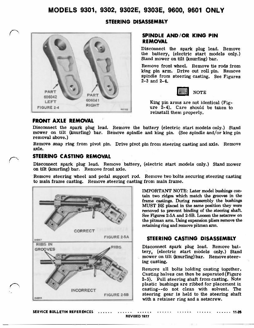
FIGURE 2-4 RIGHT 94193
SPINDLE A N D / O R KING PIN REMOVAL
Disconnect the spark plug lead. Remove the battery, (electric start models only.) Stand mower on tilt (knurfing) bar. Remove front wheel. Remove tie rods from king pin arm. Drive out roll pin. Remove spindle from steering casting. See Figures 2-3 and 2-4.
NOTE
King pin a rms a re not identical (Fig- ure 2-4). Care should be taken to reinstall them properly.
FRONT AXLE REMOVAL Disconnect the spark plug lead. Remove the battery (electric start models only.) Stand mower on tilt (knurfing) bar. Remove spindle and king pin. (See spindle and/or king pin removal above.) Remove snap ring from pivot pin. Drive pivot pin from steering casting and axle. Remove axle. STEERING CASTING REMOVAL Disconnect spark plug lead. Remove battery, (electric start models only.) Stand mower on tilt (knurfing) bar. Remove front axle. Remove steering wheel and pedal support rod. Remove two bolts securing steering casting to main frame casting. Remove steering casting from main frame.
CORRECT
04267 FIGURE 2-5A
RIBS IN
I
INCORRECT FIGURE 2-5B
04268
IMPORTANT NOTE: Later model bushings con- tain two ridges which match the grooves in the frame castings. During reassembly the bushings MUST BE placed in the same position they were removed to prevent binding of the steering shaft. See Figures 2-5A and 2-5B. Loosen the setscrew on the pitman arm. Using expansion pliers remove the retaining ring and remove pitman arm.
STEERING CASTING DISASSEMBLY Disconnect spark plug lead. Remove bat- tery, (electric start models only.) Stand mower on tilt (knurfing) bar. Remove steer- ing casting. Remove all bolts holding casting together. Casting halves can then be separated (Figure 2-5). Pull steering shaft from casting. Note plastic bushings a r e ribbed for placement in casting--do not clean with solvent. The steering gear is held to the steering shaft with a retainer ring and a setscrew.
MODELS 9301, 9302, 9302E, 9303E, 9600, 9601 ONLY
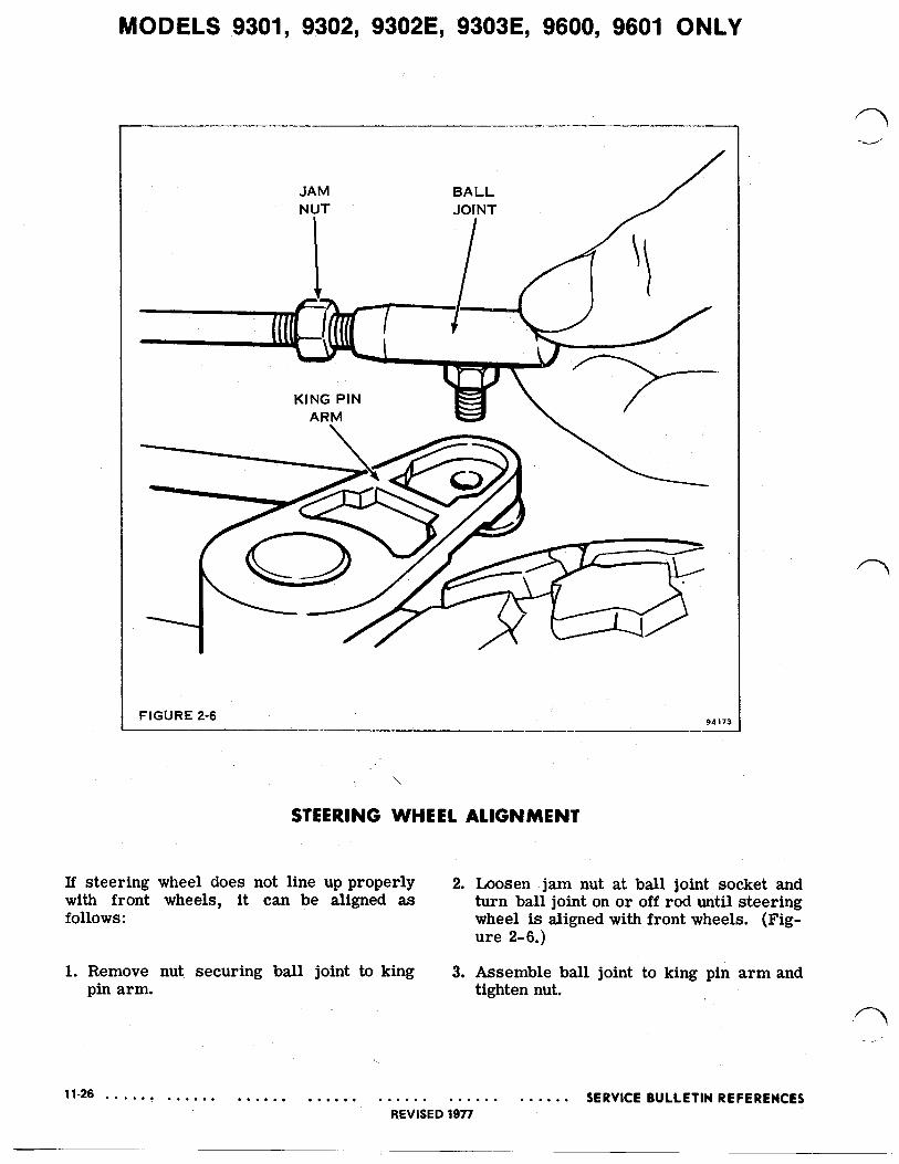
FIGURE 2-6 94173
\
STEERING WHEEL ALIGNMENT !
If steering wheel does not line up properly 2. Loosen ,jam nut at ball joint socket and with front wheels, it can be aligned as turn ball joint on o r off rod until steering follows: wheel is aligned with front wheels. (Fig-
ure 2-6.j
1. Remove nut securing ball joint to king 3. Assemble ball joint to king pin a rm and pin arm. tighten nut.
MODELS 9301, 9302, 9302E, 9303E, 9600, 9601 ONLY
SECTION 3
ADJUSTMENTS
POWER FOR DRIVING
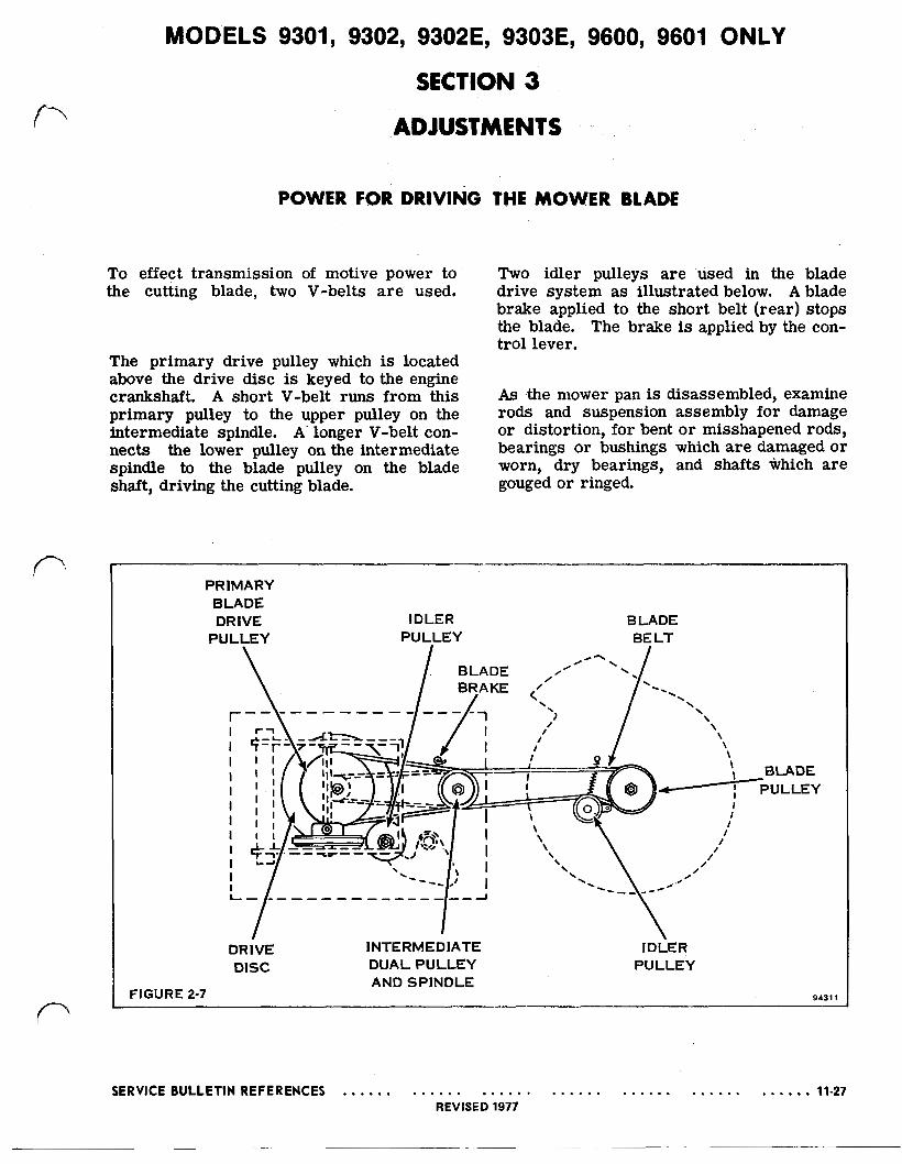
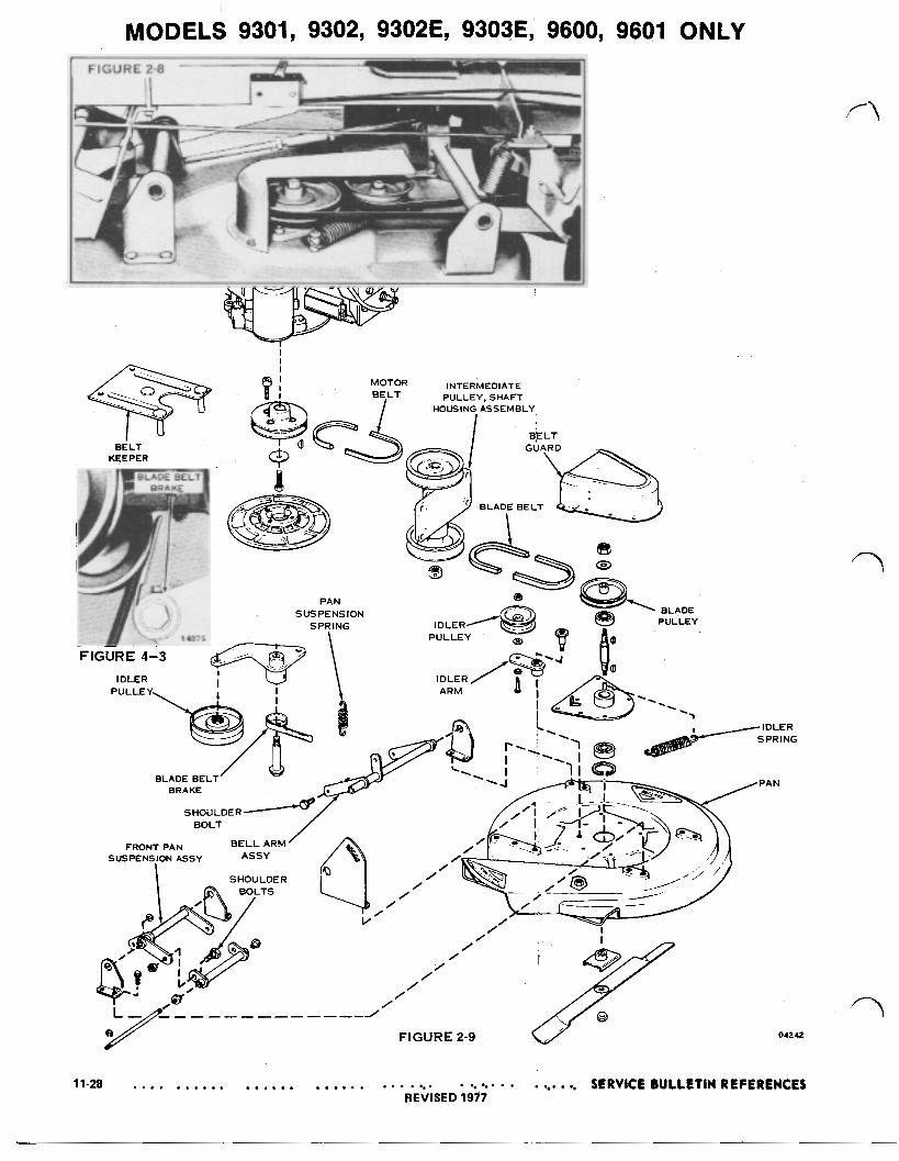
To effect transmission of motive power to the cutting blade, two V-belts a r e used.
The primary drive pulley which is located above the drive disc is keyed to the engine crankshaft. A short V-belt runs from this primary pulley to the upper pulley on the intermediate spindle. A' longer V-belt con- nects the lower pulley on the intermediate spindle to the blade pulley on the blade shaft, driving the cutting blade.
THE MOWER BLADE
Two idler pulleys are used in the blade drive system as illustrated below. A blade brake applied to the short belt (rear) stops the blade. The brake is applied by the con- trol lever.
As .the mower pan is disassembled, examine rods and suspension assembly for damage or distortion, for bent o r misshapened rods, bearings or bushings which a re damaged o r worn, dry bearings, and shafts which are gouged or ringed.
FIGURE
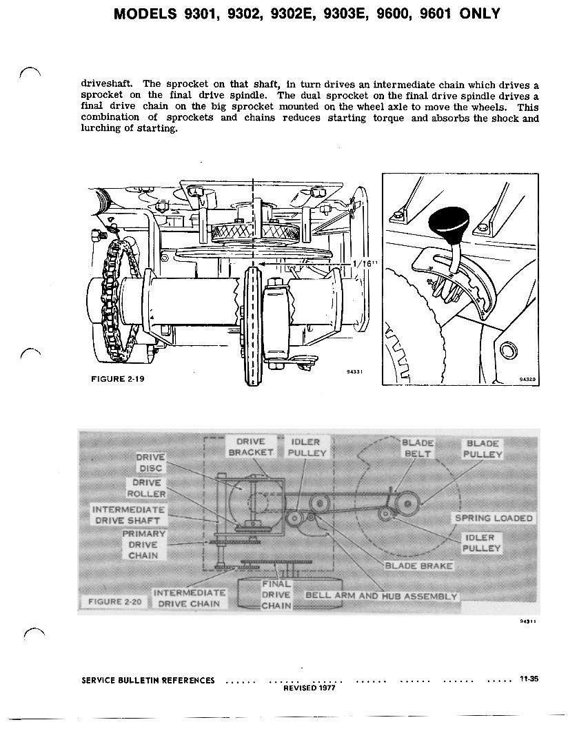
PRIMARY BLADE DRIVE IDLER BLADE
PULLEY PULLEY BELT
DRIVE INTERMEDIATE IDLER DISC DUAL PULLEY PULLEY
AND SPINDLE 2-7 94311
SERVICE BULLETIN REFERENCES 11-27 REVISED 1977
04242
11-28 SERVICE BULLETIN REFERENCES REVISED 1977
MODELS 9301, 9302, 9302E, 9303E. 9600, 9601 ONLY MOWER PAN DISASSEMBLY
I 1
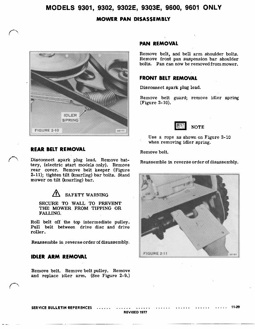
REAR BELT REMOVAL
Disconnect spark plug lead. Remove bat- tery, (electric start models only). Remove rear cover. Remove belt keeper (Figure 2-11); tighten tilt (knurfing) bar bolts. Stand mower on tilt (knurfing) bar.
SAFETY WARNING
SECURE TO WALL TO PREVENT THE MOWER FROM TIPPING OR FALLING.
Roll belt off the top intermediate pulley. Pull belt between drive disc and drive roller.
Reassemble in reverse order of disassembly.
PAN REMOVAL
Remove belt, and bell arm shoulder bolts. Remove front pan suspension bar shoulder bolts. Pan can now be removed from mower.
FRONT BELT REMOVAL Disconnect spark plug lead.
NOTE
Use a rope as shown on Figure 2-10 when removing idler spring.
Remove belt.
Reassemble in reverse order of disassembly.
IDLER ARM REMOVAL FIGURE 2-11 94181 ~-
Remove belt. Remove belt pulley. Remove and replace idler arm. (See Figure 2-9.)
SERVICE BULLETIN REFERENCES 11-29 REVISED 1977

MODELS 9301, 9302, 9302E, 9303E, '9600, 9601 ONLY BLADE BRAKE ADJUSTMENT
When the blade control lever is placed in SAFETY WARNING the “off” position, an adjustable leaf spring connected to the bell a rm and hub assembly is forced against the drive belt preventing the blade from rotating.
BLADE NUT MUST BE TIGHT BE- FORE ADJUSTING BLADE BRAKE TENSION. SECURE MOWER TO PREVENT TIPPING OR FALLING.
The blade brake leaf spring be ad- 1. Use a right angle screwdriver to loosen justed to obtain blade stoppage in not less than (4) four or more than (6) six seconds with engine operating at 3600 RPM.
the lock screw on the blade brake leaf spring. See Figure 2-12.
To obtain proper blade brake tension: 2. Move the spring in or out until desired position, is obtained.
Disconnect spark Plug lead- Remove bat- 3. Tighten lock Screw Lower tery, (electric start models only.) mower back on wheels. Stand mower on tilt (knurfing) bar. 4. Start engine, letting it run about (2) two
minutes' to warm up.
5. Place blade control lever in "off" posi- tion. Check blade stoppage by visually observing drive pulley. DO NOT place
FIGURE 2-12 94184
11-30 SERVICE BULLETIN REFERENCES REVISED 1977

MODELS 9301, 9302, 9302E, 9303E, 9600, 9601 ONLY PAN TILT ADJUSTMENT- 26” & 30’’ MODELS
1. Locate the mower on a flat level surface such as a driveway, sidewalk, garage floor, etc.
2. Place the height adjustment lever in the middle setting.
3. Rotate the blade until the cutting edge is facing the front of the mower and meas- ure the distance from the ground to the tip of the cutting edge of the blade. See Figure 2- 13.
4. Rotate the blade 180º and measure (from rear of pan) the distance’ from the ground
to the tip of the cutting edge of the blade. See Figure 2-13.
5. The mower pan tilt is Correct if the measurement obtained in step 4 is 1/4 inch higher than the measurement ob- tained in step 3.
6. The pan tilt may be adjusted by removing the cotter pin on one end of the tilt adjust rod, loosen the jam nut on the clevis and turn the rod in o r out of the clevis until the required tilt is reached. Secure clevis with jam nut. See Figure 2-14.
7. See page 11-54 and check for bent blade.
FIGURE 2-14 94276

MODELS 9301, 9302, 9302E, 9303E, 9600, 9601 ONLY
SECTION 4 THEORY OF OPERATION
INTRODUCTION The Lawn-Boy Riding Mower is powered by a vertical shaft four-cycle gasoline engine mounted on the rear of the machine. The vertical crankshaft of the engine drives both the wheels and the cutting blade, with the speed of the forward motion determined by the Speed Selector Lever which provides three forward speeds, a reverse, and a neutral position. The speed of the cutting blade on the mower is determined by the revolutions per minute of the engine. The throttle allows varying speeds of the engine up to a maximum of 3600 rpm.
Because of the selective controls of the Rider, it is possible to drive the machine without the cutting blade rotating, to drive the wheels slowly while the cutting blade and engine are at full 3600 rpm for maximum cutting in heavy growth, and to regulate from the driver's seat many combinations of speed and cutting heights.
FIRST POSITION
FIGURE 2-15
94316
POWER FOR DRIVING THE WHEELS
The driving of the wheels is accomplished through the use of a large aluminum drive disc which is keyed to the vertical crankshaft of the engine. Because this disc always rotates at the speed of the engine, transfer of motive power at varying speeds is accomplished through the use of linkages, by bringing the rubber-tired drive roller into contact with the disc at three different positions from the center of the disc. The linear speed of any point on a wheel is highest when the point is at the rim and slowest at the hub. The first position
MODELS 9301, 9302, 9302E, 9303E, 9600, 9601 ONLY
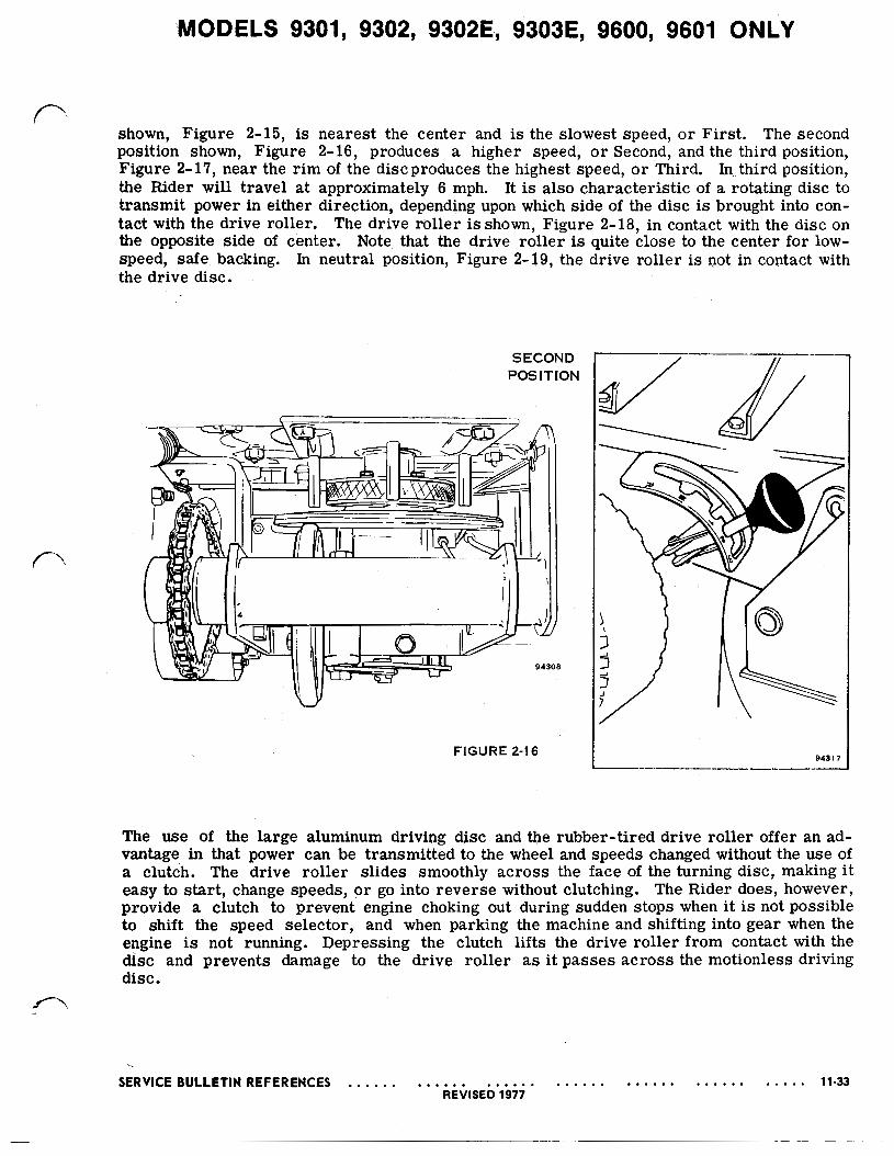
shown, Figure 2-15, is nearest the center and is the slowest speed, or First. The second position shown, Figure 2-16, produces a higher speed, o r Second, and the third position, Figure 2-17, near the rim of the disc produces the highest speed, or Third. In third position, the Rider will travel at approximately 6 mph. It is also characteristic of a rotating disc to transmit power in either direction, depending upon which side of the disc is brought into con- tact with the drive roller. The drive roller is shown, Figure 2-18, in contact with the disc on the opposite side of center. Note that the drive roller is quite close to the center for low-
' , drive roller is not in contact with speed, safe backing. In neutral position, Figure 2-19, the the drive disc.
SECOND POSITION
FIGURE 2-16
\
94317
The use of the large aluminum driving disc and the rubber-tired drive roller offer an ad- vantage in that power can be transmitted to the wheel and speeds changed without the use of a clutch. The drive roller slides smoothly across the face of the turning disc, making i t easy to start, change speeds, or go into reverse without clutching. The Rider does, however, provide a clutch to prevent engine choking out during sudden stops when it is not possible to shift the speed selector, and when parking the machine and shifting into gear when the engine is not running. Depressing the clutch lifts the drive roller from contact with the disc and prevents damage to the drive roller as it passes across the motionless driving disc.
SERVICE BULLETIN REFERENCES 11-33 REVISED 1977

MODELS 9301, 9302, 9302E, 9303E,' 9600, 9601 ONLY
Inherent in the driving system of disc and drive roller making sudden contact is a tendency to lurch or buck when the machine is started from a dead stop. To make smoother starts possible, a series of sprockets and chains transmits the motive power from the drive roller to the wheels. In Figure 2-20 is shown the smooth transmission of power as the sprocket on the drive roller shaft turns a primary chain connected to the sprocket on the intermediate
REVERSE POSITION
FIGURE 2-18
11-34 REVISED 1977
SERVICE BULLETIN REFERENCES
MODELS 9301, 9302, 9302E, 9303E, 9600, 9601 ONLY
driveshaft. The sprocket on that shaft, in turn drives an intermediate chain which drives a sprocket on the final drive spindle. The dual sprocket on the final drive spindle drives a final drive chain on the big sprocket mounted on the wheel axle to move the wheels. This combination of sprockets and chains reduces starting torque and absorbs the shock and lurching of starting.
94311
SERVICE BULLETIN REFERENCES 11-35 REVISED 1977
MODELS 9301, 9302, 9302E, 9303E, '9600, 9601 ONLY
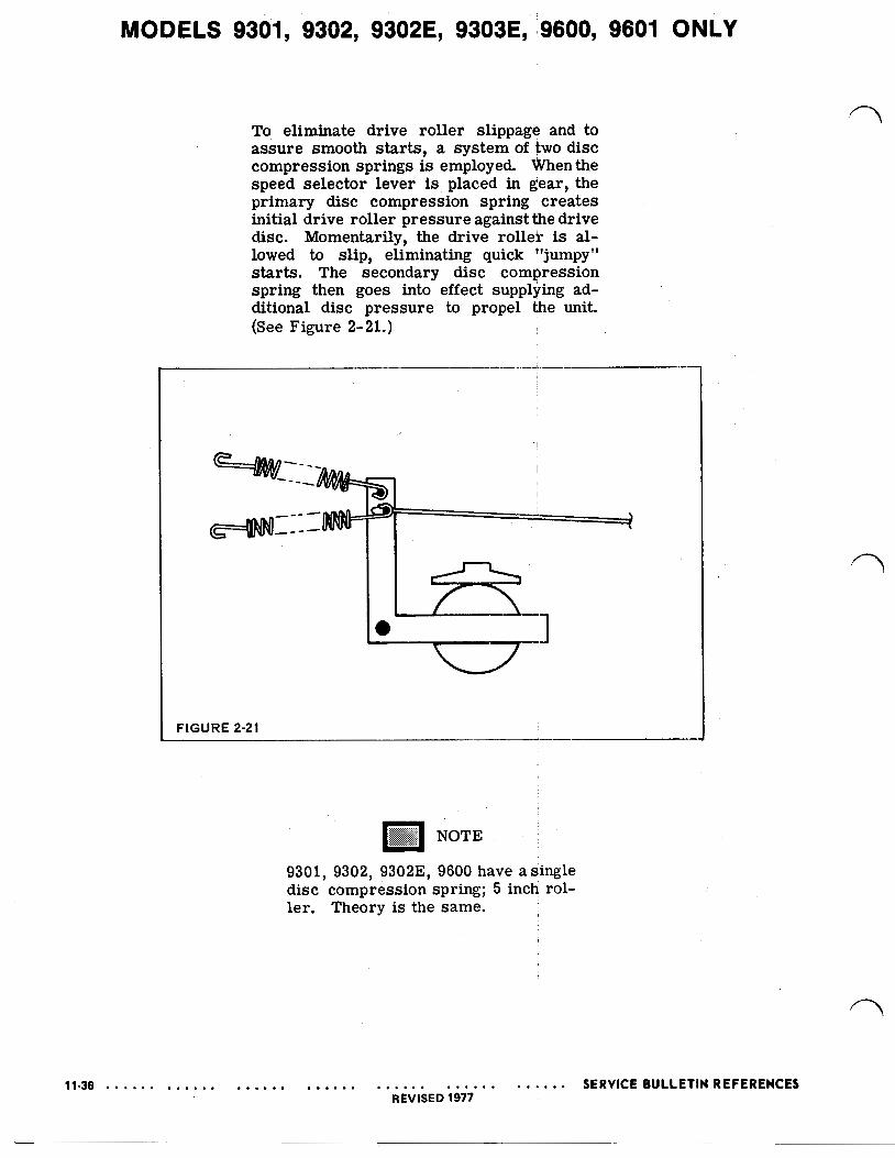
To eliminate drive roller slippage and to assure smooth starts, a system of two disc compression springs is employed. When the speed selector lever is placed in gear, the primary disc compression spring creates initial drive roller pressure against the drive disc. Momentarily, the drive roller is al- lowed to slip, eliminating quick "jumpy" starts. The secondary disc compression spring then goes into effect supplying ad- ditional disc pressure to propel the unit. (See Figure 2-21.)
FIGURE 2-21 i-
n NOTE 9301, 9302, 9302E 9600 have a single disc compression spring; 5 inch rol- ler. Theory is the same.

MODELS 9302, 9302E, 9303E, 9600, 9601 ONLY
NOTE
CHAIN TENSIONER 9303. 9303E, 9601
COMPRESSION SECONDARY
SERVICE BULLETIN REFERENCES 11-37 REVISED 1977
MODELS 9301, 9302, 9302E, 9303E, 9600, 9601 ONLY PRIMARY DRIVE SERVICING
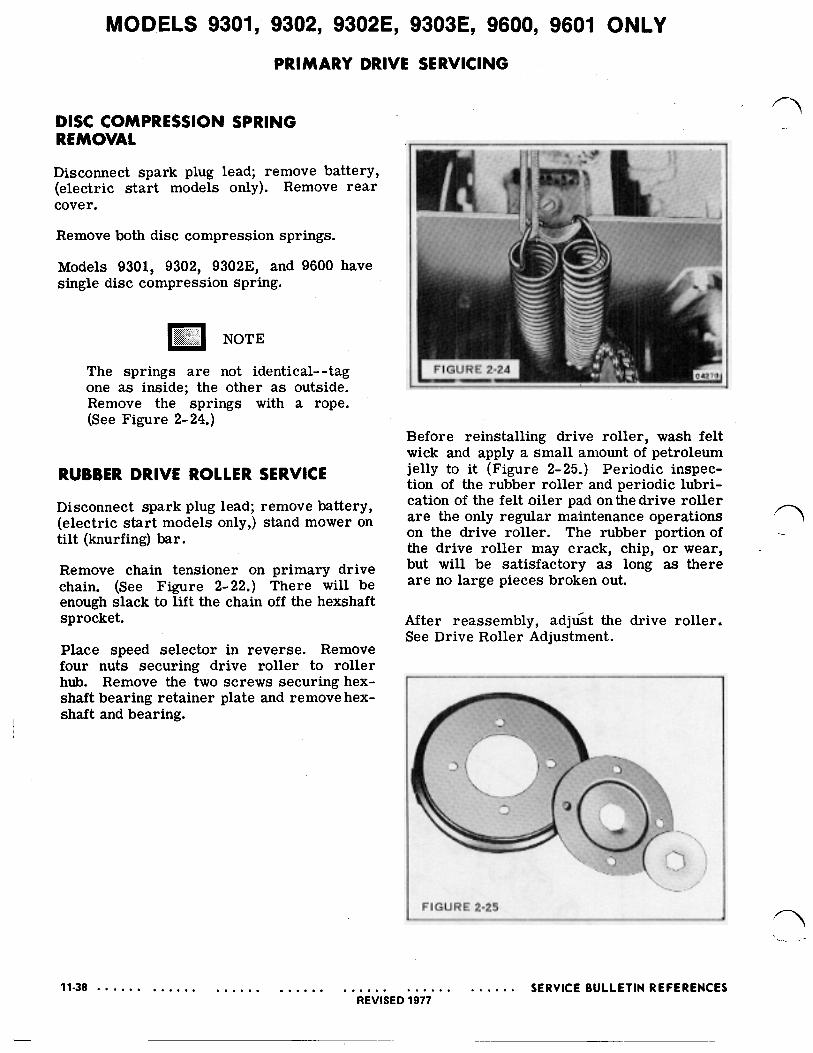
DISC COMPRESSION SPRING REMOVAL
Disconnect spark plug lead; remove battery, (electric start models only). Remove rear cover.
Remove both disc compression springs.
Models 9301, 9302, 93023, and 9600 have single disc compression spring.
The springs are not identical--tag one as inside; the other a s outside. Remove the springs with a rope. (See Figure 2-24.)
RUBBER DRIVE ROLLER SERVICE
Disconnect spark plug lead; remove battery, (electric start models only,) stand mower on tilt (knurfing) bar.
Remove chain tensioner on primary drive chain. (See Figure 2-22.) There will be enough slack to lift the chain off the hexshaft sprocket.
Place speed selector in reverse. Remove four nuts securing drive roller to roller hub. Remove the two screws securing hex- shaft bearing retainer plate and remove hex- shaft and bearing.
_-
Before reinstalling drive roller, wash felt wick and apply a small amount of petroleum jelly to it (Figure 2-25.) Periodic inspec- tion of the rubber roller and periodic lubri- cation of the felt oiler pad on the drive roller are the only regular maintenance operations on the drive roller. The rubber portion of the drive roller may crack, chip, or wear, but will be satisfactory as long as there are no large pieces broken out.
After reassembly, adjust the drive roller. See Drive Roller Adjustment.
FIGURE 2-25
11-38 e . e . . . . . e . . . . . . . . a s . SERVICE BULLETIN REFERENCES REVISED 1977
MODELS 9301, 9302, 9302E, 9303E, 9600, 9601 ONLY DRIVE ASSEMBLY ADJUSTMENTS
DRIVE ROLLER TRAVEL HORIZONTAL
Disconnect spark plug lead; remove battery, (electric start models only,) stand mower on tilt (knurfing) bar.
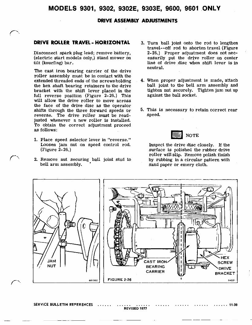
The cast iron bearing carrier of the drive roller assembly must be in contact with the extended threaded ends of the screws holding the hex shaft bearing retainers to the drive bracket with the shift lever placed in the full reverse position (Figure 2-26.) This will allow the drive roller to move across the face of the drive disc as the operator shifts through the three forward speeds or reverse. The drive roller must be read- justed whenever a new roller is installed. To obtain the correct adjustment proceed as follows:
1. Place speed selector lever in "reverse." Loosen jam nut on speed control rod. (Figure 2-26.)
2. Remove nut securing ball joint stud to bell arm assembly.
3. Turn ball joint onto the rod to lengthen travel--off rod to shorten travel (Figure 2-26.) Proper adjustment does not nec- essarily put the drive roller on center line of drive disc when shift lever is in neutral.
4. When proper adjustment is made, attach ball joint to the bell arm assembly and tighten nut securely. Tighten jam nut up against the ball socket.
5. This is necessary to retain correct rear speed.
Inspect the drive disc closely. If the surface is polished the rubber drive roller will slip. Remove polish finish by rubbing in a circular pattern with sand paper or emery cloth.
681902 FIGURE 2-26 94331
SERVICE BULLETIN REFERENCES 11-39 REVISED 1977
MODELS 9301, 9302, 9302E, 9303E, 9600, 9601 ONLY
FIGURE 2-27 94332
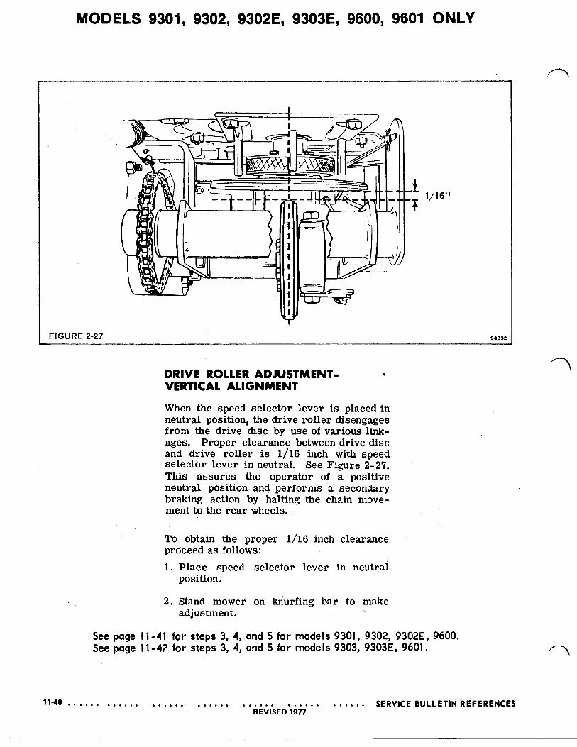
DRIVE ROLLER ADJUSTMENT- VERTICAL ALIGNMENT When the speed selector lever is placed in neutral position, the drive roller disengages from the drive disc by use of various link- ages. Proper clearance between drive disc and drive roller is 1/16 inch with speed selector lever in neutral. See Figure 2-27. This assures the operator of a positive neutral position and performs a secondary braking action by halting the chain move- ment to the rear wheels.
To obtain the proper 1/16 inch clearance proceed as follows: 1. Place speed selector lever in neutral
position.
2. Stand mower on knurfing bar to make adjustment.
See page 11-41 for steps 3, 4, and 5 for models 9301, 9302, 9302E, 9600. See page 11-42 for steps 3, 4, and 5 for models 9303, 9303E, 9601.
11-40 SERVICE BULLETIN REFERENCES REVISED
MODELS 9301, 9302, 9302E, 9600 ONLY

MODELS 9303, 9303E, 9601, ONLY
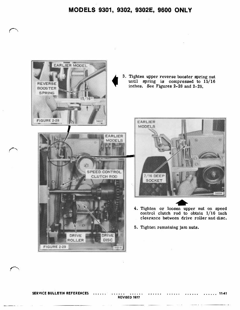
3. Tighten upper reverse booster spring nut until spring is compressed 1 1/2". See Figure 2-30.
4. Tighten or loosen upper nut on, speed control clutch rod to obtain 1/16 inch clearance between roller and disc.
5. Tighten remaining jam nuts.
SERVICE BULLETIN REFERENCES 11-42 REVISED 1977
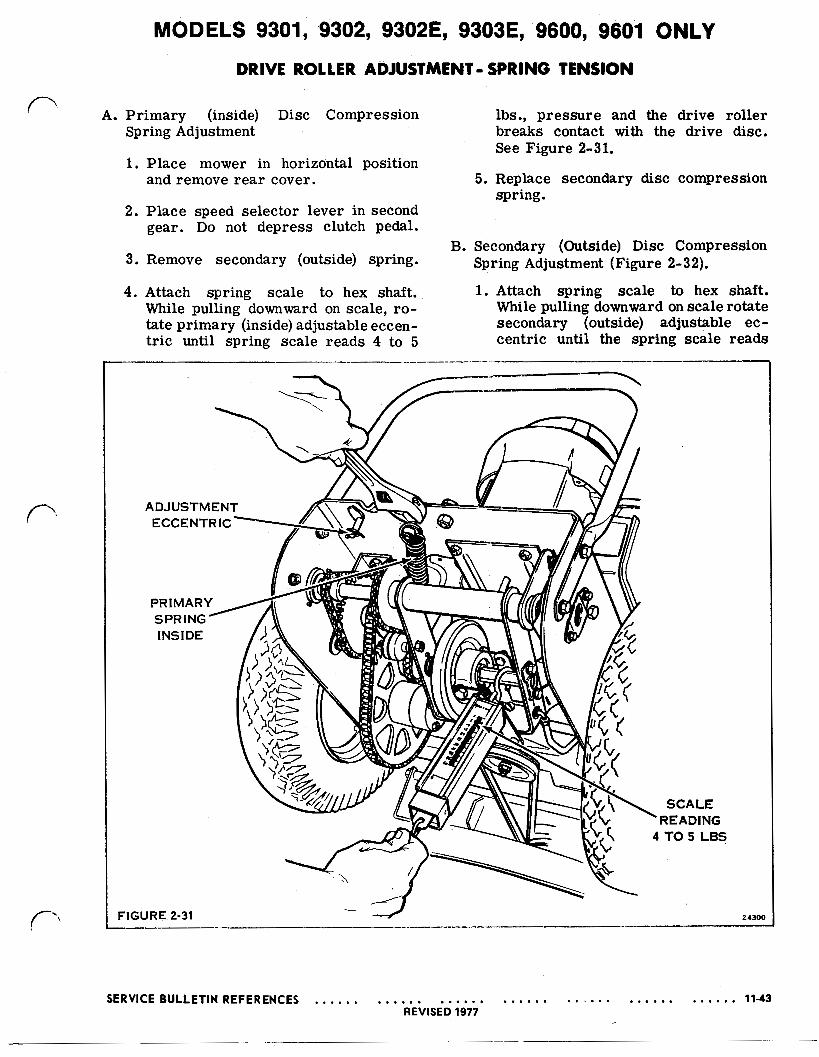
MODELS 9301, 9302, 9302E, 9303E, 9600, 9601 ONLY DRIVE ROLLER ADJUSTMENT- SPRING TENSION
A. Primary (inside) Disc Compression lbs., pressure and the drive roller Spring Adjustment breaks contact with the drive disc.
1. Place mower in horizontal position and remove rear cover.
2. Place speed selector lever in second gear. Do not depress clutch pedal.
3. Remove secondary (outside) spring.
4. Attach spring scale to hex shaft. While pulling downward on scale, ro- tate primary (inside) adjustable eccen- tr ic until spring scale reads 4 to 5
See Figure 2-31.
5. Replace secondary disc compression spring.
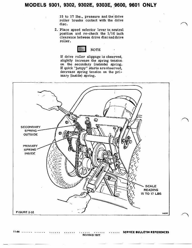
B. Secondary (Outside) Disc Compression Spring Adjustment (Figure 2-32).
1. Attach spring scale to hex shaft. While pulling downward on scale rotate secondary (outside) adjustable ec- centric until the spring scale reads
FIGURE 2-31 24300
SERVICE BULLETIN REFERENCES 11-43 REVISED 1977
MODELS 9301, 9302, 9302E, 9303E, i9600, 9601 ONLY
15 to 17 lbs., pressure and the drive roller breaks contact with the drive disc.
2. Place speed selector lever in neutral position and re-check the 1/16 inch clearance between drive disc and, drive roller.
NOTE
If drive roller slippage is observed, slightly increase the spring tension on the secondary (outside) spring. If quick "jumpy" starts are observed, decrease spring tension on the pri- mary (inside) spring.
FIGURE 2-32 04299
MODELS 9301, 9302, 9302E, 9303E, 9600, 9601 ONLY
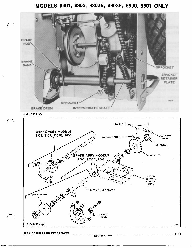
BRAKE ROD\
BRAKE BAND.
14076
BRAKE'DRUM INTERMEDIATE SHAFT' FIGURE 2-33
ROLL PINS
PRIMARY CHAIN SECONDARY-
CHAIN
SPROCKET
ASSY MODELS
INTERMEDIATE SHAFT
FIGURE 2-34 0425
SERVICE BULLETIN REFERENCES 11-45 REVISED 1977
MODELS 9301, 9302, 9302E, 9303E, '9600, 9601 ONLY
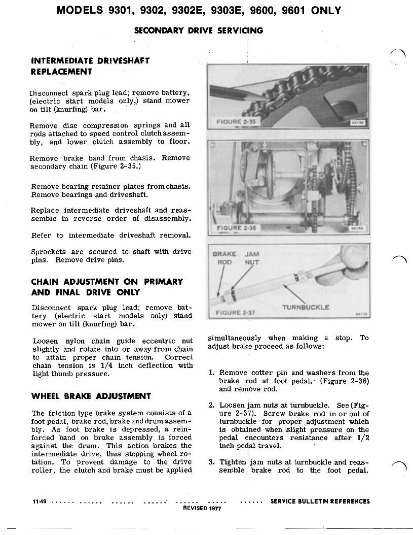
SECONDARY .DRIVE SERVICING
Remove brake band from chasis. Remove secondary chain (Figure 2-35.)
Remove bearing retainer plates from chasis. Remove bearings and driveshaft.
Replace intermediate driveshaft and reas- semble in reverse order of disassembly.
Loosen nylon chain guide eccentric nut slightly and rotate into or away from chain to attain proper chain tension. Correct chain tension is 1/4 inch deflection with light thumb pressure.
WHEEL BRAKE ADJUSTMENT
The friction type brake system consists of a foot pedal, brake rod, brake and drum assem- bly. A s foot brake is depressed, a rein- forced band on brake assembly is forced against the drum. This action brakes the intermediate drive, thus stopping wheel ro- tation. To prevent damage to the drive roller, the clutch and brake must be applied
simultaneously when making a stop. To adjust brake proceed a s follows:
1. Remove' cotter pin and washers from the brake rod at foot pedal. (Figure 2-36) and remove rod.
2. Loosen jam nuts at turnbuckle. See (Fig- ure 2-37). Screw brake rod in o r out of turnbuckle for proper adjustment which is obtained when slight pressure on the pedal encounters resistance after 1/2 inch pedal travel.
3. Tighten, jam nuts at turnbuckle and reas- semble brake rod to the foot pedal.

MODELS 9301, 9302, 9302E, 9303E, 9600, 9601 ONLY
FIGURE 2-38 1 A 0 7 9
FIGURE 2-39 04247

MODELS 9301, 9302, 9302E, 9303E, ‘9600, 9601 ONLY FINAL DRIVE DISASSEMBLY
DIFFERENTIAL REMOVAL Disconnect spark plug lead; remove battery (elec- tric start models only).
SAFETY WARNING
WHEN STANDING MOWER ON END, ALWAYS ANCHOR IT TO PREVENT FROM TIPPING OR FALLING. ALSO
TION AND DISCONNECT SPARK PLUG LEAD.
PLACE THROTTLE IN “STOP” POSI-
Stand mower on tilt (knurfing) bar. Remove rear belt. !
Remove rods from carrier bracket and disc compression springs. Lower bracket to floor.
Remove chain, rear wheels and axle bear- ings.
Place blade control lever in “on” position and slide differential out.
NOTE
Be careful not to mar the drive disc with the differential sprocket teeth when removing the differential.
Reassemble in reverse order of disassem- bly. After reassembly place blade control lever in off position.
DIFFERENTIAL DISASSEMBLY Remove differential. (See above.)
Remove four bolts holding differential and sprocket together. Differential halves can then be separated. Inspect parts, etc., (Fig- ure 2-39.
When reassembling, pack differential with 3 ounces of Lawn-Boy “A” grease/
11-48 SERVICE BULLETIN REFERENCES REVISED 1977
MODELS 9301, 9302, 9302E, 9303E, 9600, 9601 ONLY
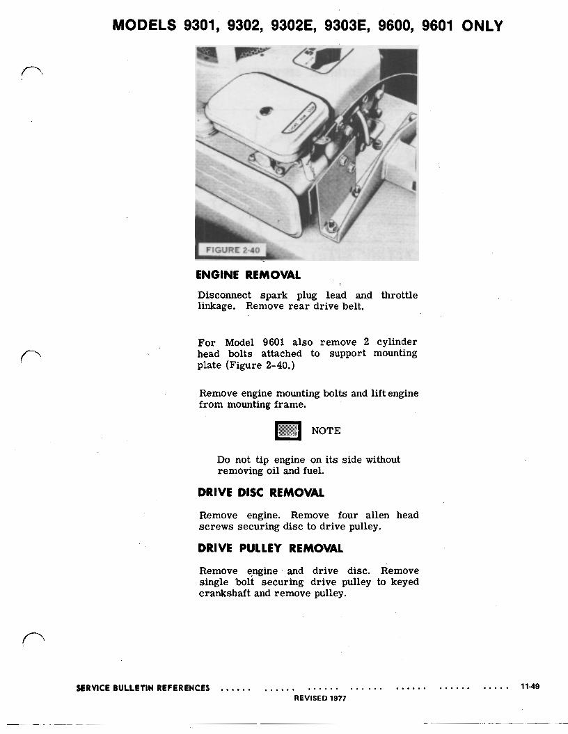
ENGINE REMOVAL Disconnect spark plug lead and throttle linkage. Remove rear drive belt.
For Model 9601 also remove 2 cylinder head bolts attached to support mounting plate (Figure 2-40.)
Remove engine mounting bolts and lift engine from mounting frame.
NOTE
Do not tip engine on its side without removing oil and fuel.
DRIVE DISC REMOVAL
Remove engine. Remove four allen head screws securing disc to drive pulley.
DRIVE PULLEY REMOVAL
Remove engine and drive disc. Remove single bolt securing drive pulley to keyed crankshaft and remove pulley.
SERVICE BULLETIN REFERENCES 11-49 REVISED 1977
MODELS 9302E, 9303E ONLY
SECTION 5
ELECTRICAL SERVICING
FIGURE 2-41 L
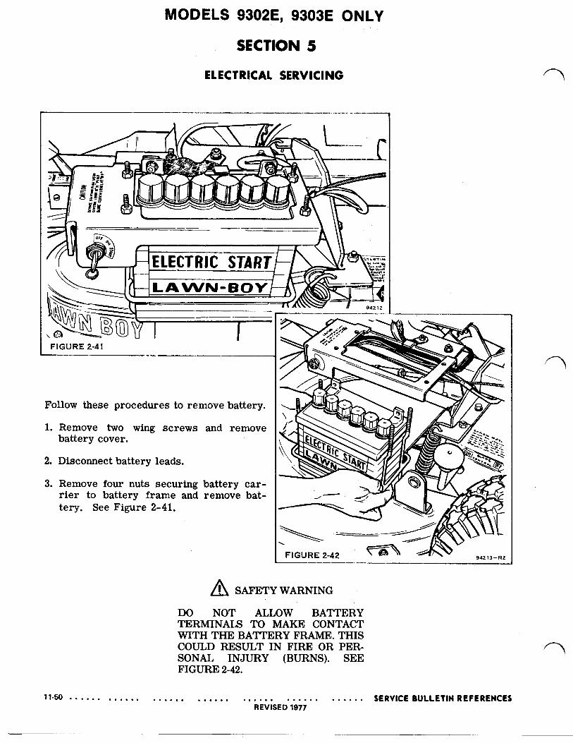
Follow these procedures to remove battery.
1. Remove two wing screws and remove battery cover.
2. Disconnect battery leads.
3. Remove four nuts securing battery car- rier to battery frame and remove bat- tery. See Figure 2-41.
SAFETY WARNING
DO NOT ALLOW BATTERY TERMINALS TO MAKE CONTACT WITH THE BATTERY FRAME. THIS
SONAL INJURY (BURNS). SEE COULD RESULT IN FIRE OR PER-
FIGURE 2-42.
11-50 SERVICE BULLETIN REFERENCES REVISED 1977
MODELS 9302E, 9303E ONLY
DIODE I GROOVED END
DIODE
FIGURE 2-43 FRONT OF MOWER 94256
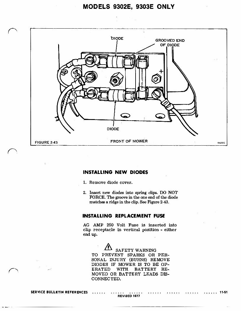
INSTALLING NEW DIODES
1. Remove diode cover.
2. Insert new diodes into spring clips. DO NOT FORCE. The groove in the one end of the diode matches a ridge in the clip. See Figure 2-43.
INSTALLING REPLACEMENT FUSE AG AMP 250 Volt Fuse is inserted into clip receptacle in vertical position either end up.
SAFETY WARNING
SONAL INJURY (BURNS) REMOVE TO PREVENT SPARKS OR PER-
DIODES IF MOWER IS TO BE OP- ERATED WITH BATTERY RE- MOVED OR BATTERY LEADS DIS- CONNECTED.
SERVICE BULLETIN REFERENCES 11-51 REVISED 1977
MODELS 9301, 9302, 9302E, 9303E, 9600, 9601 ONLY
SECTION 6
PREVENTIVE MAINTENANCE
To obtain peak performance and long life from the engine the air cleaner must be serviced regularly. Under normal condi- tions an air cleaner should be serviced every 10 hours of operation, oftener, if under dusty condition. To service air cleaner, pour old oil from bowl. Wash ele- ment thoroughly in solvent and dry. Clean bowl and refill with same type of oil used in crankcase. See engine Owner’s Manual.
CRANKCASE O I L
TIRES
Recommended pressure for front wheels on Models 9601, 9303, 93033 is 15-17 lbs. Rear pressure for the same models is 22- 25 lbs.
BATTERY
Check battery fluid level every 10 hours of operation.
Add distilled water to f i l l ring.
BLADE CARE
A blade will naturally become dull with use. It can be quickly sharpened with a few strokes of a file or sharpening stone. SHARPEN ONLY THE CUTTING EDGE. A blade that is not straight or properly bal- anced can cause engine vibration; loss of engine power. Excessive vibration can lead to engine (usually crankshaft) damage if allowed to continue. Imbalance can be caused by uneven wear o r impact damage. Minor imbalance can usually be corrected by grinding or filing the heavy end; if not, the blade should be replaced.
gravity of battery falls below- 12.25, recharge battery.
In storage; Battery should be charged fully once per month.
SAFETY WARNING
DO NOT CHARGE AT A RATE EX- CEEDING 4 AMPS.
DO NOT allow tools to make contact with the battery terminals when installing or servicing battery.
Remove diodes if mower engine is to be op- erated with’ battery removed o r battery leads disconnected.
DO NOT tip mower up on tilt (knurfing) LUBRICATION
A. Lubricate front wheel bearings with Automo- bar without removing battery. tive Chassis Lubricant or Lawn-Boy “A” Grease. Using conventional grease gun apply lubricant DO NOT operate mower with battery cover until grease is observed at end of the bearing removed. surface.
B. Lubricate friction points whenever DIFFERENTIAL needed. All bushings are oil impregnated and do not require oil.’ All ball bearings Check differential every 50 hours. Fill to are sealed with lubricant and therefore do 3 ounce capacity with multi-purpose auto- not require periodic lubrication. motive grease.
11-52 SERVICE BULLETIN REFERENCES REVISED 1977
MODELS 9301, 9302, 9302E, -9303E, 9600, 9601 ONLY
FRICTION DRIVE
Check rubber drive roller drive disc clearance every 30 hours.
BLADE
SAFETY WARNING
DISCONNECT THE SPARK PLUG WIRE AND PLACE THE BLADE CONTROL LEVER IN THE "OFF" POSITION.
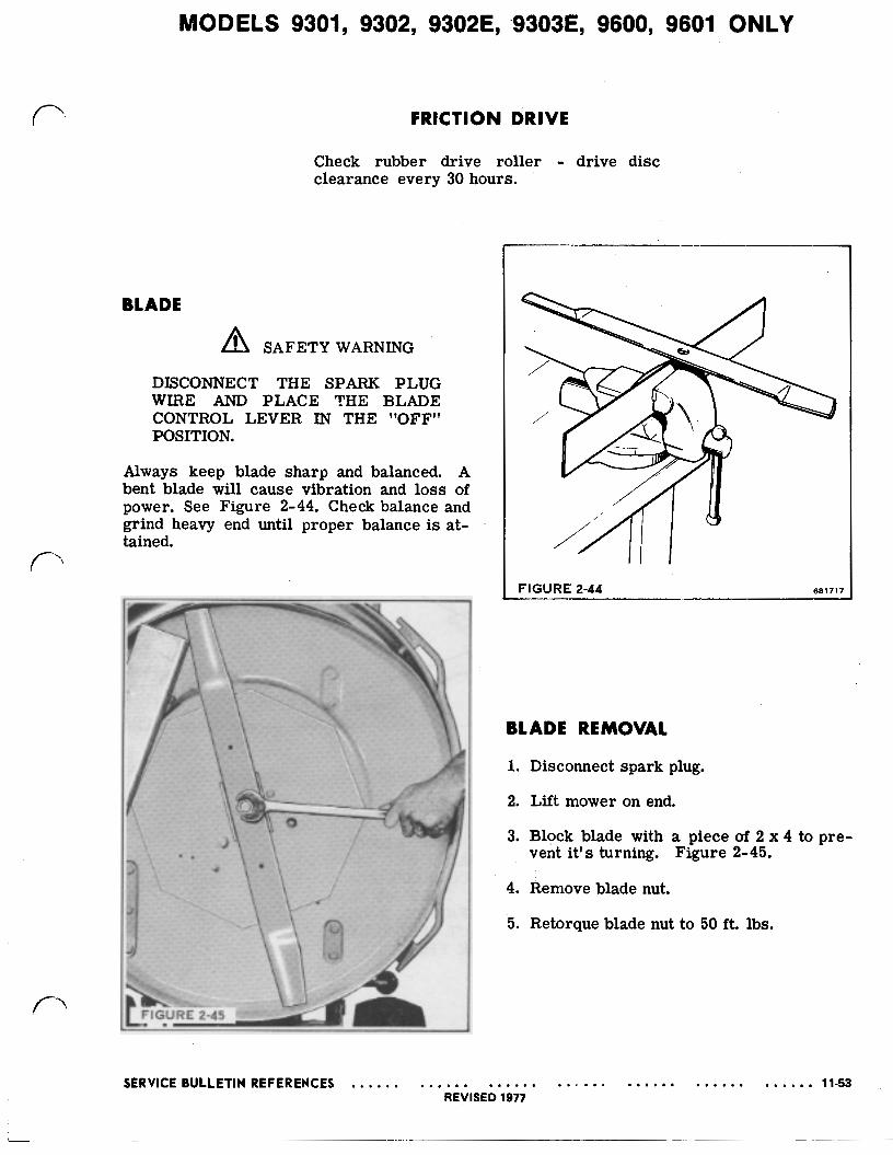
Always keep blade sharp and balanced. A bent blade will cause vibration and loss of power. See Figure 2-44. Check balance and grind heavy end until proper balance is at-
FIGURE 2-44 681717
BLADE REMOVAL
1. Disconnect spark plug.
2. Lift mower on end.
3. Block blade with a piece of 2 x 4 to pre- vent it's turning. Figure 2-45.
4. Remove blade nut.
5. Retorque blade nut to 50 ft. lbs.
MODELS 9301, 9302, 9303E, 9600, 9601 ONLY 9302E,
BENT BLADE
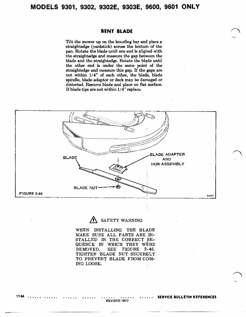
Tilt the mower up on the knurfing bar and place a straightedge (yardstick) across the bottom of the pan. Rotate the blade until one end is aligned with the straightedge and measure the gap between the blade and the straightedge. Rotate the blade until the other end is under the same point of the straightedge and measure this gap. If the gaps are not within 1/4” of each other, the blade, blade spindle, blade adaptor or deck may be damaged or distorted. Remove blade and place on flat surface. If blade tips are not within 1/4” replace.
SAFETY WARNING
WHEN INSTALLING THE BLADE
STALLED IN THE CORRECT SE- QUENCE IN WHICH THEY WERE
TIGHTEN BLADE NUT SECURELY
ING LOOSE.
MAKE SURE ALL PARTS ARE :IN-
REMOVED. SEE FIGURE 2-46.
TO PREVENT BLADE FROM COM-