Embed Size (px)
Citation preview
SBS Erection ManualVersion 1.0 - December 11, 2014
Steelway Building Systems’Erection ManualRecommended Installation Procedures& Safety Warnings

7825 Springwater Road, Aylmer, Ontario N5H 2R4 1.800.265.7740 steelway.com
Introduction .................................................................................................................................................... 2 Safety .................................................................................................................................................... 2 Building Permit .................................................................................................................................... 2 Responsibility for Erection Procedures .............................................................................................. 2 Site Conditions ..................................................................................................................................... 2 Protective Equipment .......................................................................................................................... 3Drawings ...................................................................................................................................................... 4 Approval Drawings .............................................................................................................................. 4 Erection Drawings ................................................................................................................................ 4Drawing Package ........................................................................................................................................... 5 Certificate of Design ........................................................................................................................... 5 General Information Page .................................................................................................................. 6 Reactions Information Pages .............................................................................................................. 7 Anchor Bolt Plan .................................................................................................................................. 9 Anchor Bolt Details .............................................................................................................................. 10 Roof Framing Plan ............................................................................................................................... 11 Frame Cross Section ............................................................................................................................. 13 Endwall Framing .................................................................................................................................. 15 Sidewall Framing ................................................................................................................................. 17Foundation/Squaring Methods ..................................................................................................................... 19 Site Preparation .................................................................................................................................... 19 Squaring Methods ............................................................................................................................... 20 Concrete Anchors/Anchor Bolts .......................................................................................................... 21 Foundation/Squaring Methods .......................................................................................................... 22 Tolerances on Anchor Bolt Placement ............................................................................................... 23Unloading Material ....................................................................................................................................... 24 Arrival at Building Site ......................................................................................................................... 24 Receiving .............................................................................................................................................. 24 Unloading & Material Layout .............................................................................................................. 24 Safety Precautions ................................................................................................................................ 25 Using a Spreader Bar ........................................................................................................................... 25 Unloading ............................................................................................................................................. 26 Shop Primer .......................................................................................................................................... 26 Storage ................................................................................................................................................. 26Primary and Secondary Steel Erection ......................................................................................................... 27 Assembly (Tips for Assembly) .................................................................................................................... 27 Step One to Step Seven ............................................................................................................................ 29/35 Alternate Step Two ................................................................................................................................... 36 Alternate Step Three ................................................................................................................................ 37Bolted Connections ........................................................................................................................................ 38 Basic Bolting Instructions .......................................................................................................................... 38 Snug/Tightening Sequence ....................................................................................................................... 39 Table One - Bolt Tension ........................................................................................................................... 40 Field Bolting Inspection ............................................................................................................................ 40 Other Field Connection Notes .................................................................................................................. 41Basic Sheeting Erection ................................................................................................................................. 42 Sheeting & Trim ......................................................................................................................................... 42 Wall Panel Installation .............................................................................................................................. 43 Trim Installation ......................................................................................................................................... 44 Roof Sheeting Installation ........................................................................................................................ 44 Accessories ................................................................................................................................................. 45 Inspection ................................................................................................................................................... 45Conclusion ...................................................................................................................................................... 46Glossary of Terms............................................................................................................................................ 47
Erection ManualIndex

7825 Springwater Road, Aylmer, Ontario N5H 2R4 1.800.265.7740 steelway.com p 2
This erection manual is intended to provide Steelway Building Systems’ (Steelway) Builders and/or their erectors with the procedures for erecting Steelway buildings. Steelway is not responsible for the erection of our buildings, nor do we assume any responsibility for defects that may be attributed to improper erection techniques, or negligence of other parties.
It is the builder and/or their erector’s responsibility to read this manual, and be familiar with its contents prior to erecting any new Steelway building.
Cost effective construction depends on advanced planning done during the pre-construction stages. Some Steelway buildings may require special erection techniques because of their particular use, such as: crane buildings, multi storey buildings, and buildings that integrate glass, concrete, stucco, brick or stone work. The project site should be examined and planned prior to material delivery. Alternate solutions to deal with unique site conditions should be developed at this time. A well planned, clean, and orderly job site will usually reduce erection time and costs while creating an atmosphere of safety, and offering a perception of professionalism and craftsmanship.
At Steelway, we are committed to supplying our builders with quality products and services. This manual will improve the overall quality of our product.
SafetySteelway makes every effort to incorporate safety into all of the buildings we supply. Making safety a first priority on the construction site must also be an important part to the overall installation plan. All owners, supervisors and site workers must be familiar with the workplace health and safety standards in their province as well as any local code and requirements. For projects in the United States, the Department of Labor has established Federal safety standards that all construction workers must be familiar with and practice. Failure to adhere to these standards can result in substantial fines and stop work orders.
Building PermitIt is the owner and/or contractor’s responsibility to provide to the local building department all of the necessary documentation required to obtain building permits. It is also the owner/contractor’s responsibility to arrange for any permit required site inspections. Steelway is not responsible for site inspection of any of the installed components provided.
Responsibility for Erection ProceduresWhile Steelway has made every effort possible to outline recommended installation procedures and safety warnings, it is solely the installer/erector’s responsibility for all procedures used to install the building components provided. The CISC Code of Standard Practice clearly states that the manufacturer (Steelway) is not responsible for determining the erection procedure, for checking the adequacy of the connections for the uncompleted structure, or for providing erection bracing. Nor shall Steelway be liable for loss, injury or damage resulting from faulty erection practices. Under no circumstances will Steelway accept any consequential damages.
Site ConditionsThe building site must be properly prepared to allow suitable, dry storage of delivered components and safe access in and around building foundations. All delivered components must be handled in a safe manner and stored for easy access during the erection process. All safety precautions for handling light gauge material must be followed so as not to damage the product.
Erection ManualIntroduction
7825 Springwater Road, Aylmer, Ontario N5H 2R4 1.800.265.7740 steelway.com p 3
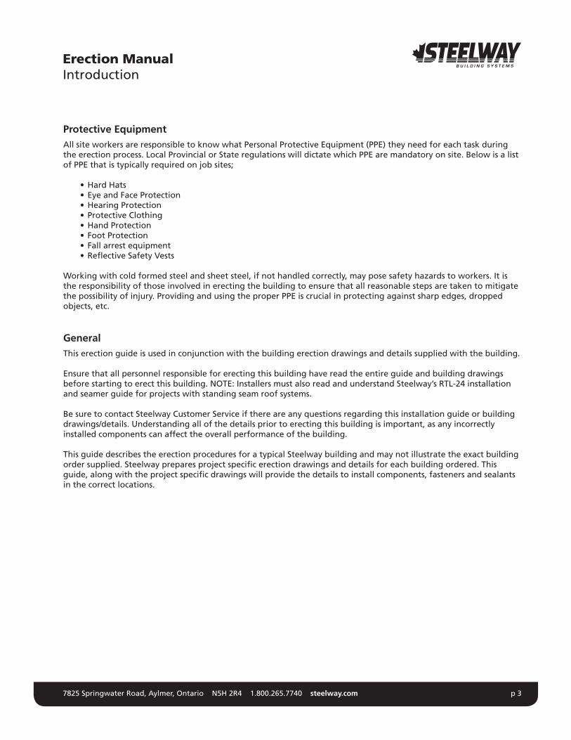
Protective EquipmentAll site workers are responsible to know what Personal Protective Equipment (PPE) they need for each task during the erection process. Local Provincial or State regulations will dictate which PPE are mandatory on site. Below is a list of PPE that is typically required on job sites;
•HardHats •EyeandFaceProtection •HearingProtection •ProtectiveClothing •HandProtection •FootProtection •Fallarrestequipment •ReflectiveSafetyVests
Working with cold formed steel and sheet steel, if not handled correctly, may pose safety hazards to workers. It is the responsibility of those involved in erecting the building to ensure that all reasonable steps are taken to mitigate the possibility of injury. Providing and using the proper PPE is crucial in protecting against sharp edges, dropped objects, etc.
GeneralThis erection guide is used in conjunction with the building erection drawings and details supplied with the building.
Ensure that all personnel responsible for erecting this building have read the entire guide and building drawings before starting to erect this building. NOTE: Installers must also read and understand Steelway’s RTL-24 installation and seamer guide for projects with standing seam roof systems.
Be sure to contact Steelway Customer Service if there are any questions regarding this installation guide or building drawings/details. Understanding all of the details prior to erecting this building is important, as any incorrectly installed components can affect the overall performance of the building.
This guide describes the erection procedures for a typical Steelway building and may not illustrate the exact building order supplied. Steelway prepares project specific erection drawings and details for each building ordered. This guide, along with the project specific drawings will provide the details to install components, fasteners and sealants in the correct locations.
Erection ManualIntroduction
7825 Springwater Road, Aylmer, Ontario N5H 2R4 1.800.265.7740 steelway.com p 4
Prior to erecting any component, refer to the building Erection Drawings to confirm the location of that component. Building components shall not be field modified unless indicated on drawings, or authorization has been given by Steelway Building Systems. Improper location and erection of components can be costly due to erection time spent disassembling and re-erecting, and could result in structural failure.
This section outlines some common features of the Erection Drawings.
Approval DrawingsDrawings that are “ISSUED FOR INFORMATION” will be marked in the revision block on each page. These drawings are only intended for co-ordination purposes only, and confirming building details before construction begins. These drawings are to be reviewed carefully to ensure that all aspects of the building are correct. Once the approval drawings have been signed by the buyer, the buyer has confirmed that Steelway Building Systems has correctly interpreted the overall contract requirements for the building, accessories, and their location.
The issue level for these drawings will be indicated with a number; a higher number will indicate the most recent versionofthedrawing.Drawingsthatare“ISSUEDFORINFORMATION”areincompleteanddonotreflectthefinalbuilding details, mark numbers, bolts, etc.
DO NOT USE APPROVAL DRAWINGS FOR ERECTION PURPOSES.
A typical approval drawing package contains the following drawings, with the certificate of design:
G1 - General Information PageR1 - Reaction PageS1 - Anchor Bolt Plan S2 - Roof Framing PlanS3 - Frame Cross SectionS4 - Endwall Framing PlanS5 - Sidewall Framing Plan
NOTE - Additional drawings maybe required depending on building size and complexity.
Erection DrawingsDrawings that are “ISSUED FOR ERECTION” will also be clearly marked in the revision block on each page. These drawings are to be used for setting anchor bolts, and erecting the rest of the building.
A typical construction drawing package contains the following drawings:
G1 - General Information PageR1 - Reaction PageS1 - Anchor Bolt Plan S2 - Roof Framing PlanS3 - Frame Cross SectionS4 - Endwall Framing PlanS5 - Sidewall Framing PlanSD1 - Structural Erection Details
NOTE - Additional drawings maybe required depending on building size and complexity.
Erection ManualDrawings

7825 Springwater Road, Aylmer, Ontario N5H 2R4 1.800.265.7740 steelway.com p 5
Certificate of Design
This page contains information about the building manufacturer and erector. It also indicates the design standards, manufacturing standards and loading used to design the building. This information is required to obtain a building permit. Check this page carefully to ensure that all information is correct.
Erection ManualDrawing Package
A660-10 Steelway Building Systems
* Initial each true statement. Mark N/A if statement does not apply.
Certificate of Design - 2010.docx Revised: May 3, 2005 Page 1 of 2
Certificate of Design and Manufacturing Conformance with
NBC, 2010 This Certificate is to affirm that all components of the steel building system described below, to be supplied by the named Manufacturer certified in accordance with CSA A660, have been or will be designed and fabricated in accordance with the following Standards to carry the loads and load combinations specified. 1. DESCRIPTION Manufacturer’s Name and Address: Steelway Building Systems, Springwater Rd., Aylmer, ON Manufacturer's Certificate No. under CSA A660:
Customer Order Number:
Building Type and Size:
(mm) Intended Use and Occupancy:
Importance Category (NBC, Sentence 4.1.2.1.(3)):
Site Location:
Applicable Building Code:
Builder's Name and Address:
Owner's Name and Address:
Engineer’s Initials *
2. DESIGN STANDARDS N/A National Building Code of Canada, 2010, Part 4: Structural Design CAN/CSA-S16-09, Limit States Design of Steel Structures CAN/CSA-S136-07, North American Specification for the Design of Cold-Formed Steel Structural Members Other (specify):
dated
3. MANUFACTURING STANDARDS N/A (a) Fabrication has been or will be in accordance with CAN/CSA-S16 and CAN/CSA-S136, as applicable. (b) Welding has been or will be performed in accordance with CSA W59 and CAN/CSA-S136, as applicable. (c) The Manufacturer has been certified in accordance with CSA W47.1, for Division 1 or Division 2, and/or CSA W55.3, if applicable. (d) Welders have been qualified in accordance with CSA-W47.1. 4. PURLIN STABILITY N/A Purlin braces are provided in accordance with CAN/CSA-S136, Clause D3 and Appendix B, Clause D3.2.2. In particular, for a standing seam roof supported on movable clips, braces providing lateral support to both top and bottom purlin flange have been or will be provided. The number of rows is determined by analysis but in no case is less than 1 for spans up to 7m inclusive or less than 2 for spans greater than 7m. 5. LOADS (a) Snow, Ice, and Rain Load N/A 1-in-50 year ground snow load, Ss,
(kPa) 1-in-50 year associated rain load, Sr,
(kPa) Wind exposure factor, Cw,
Importance factor, Is,
Roof snow load, S,
(kPa) Drift load considered (NBC Sub-section 4.1.6.2.8) refer to drawing of specific building Specified rain load (NBC, Article 4.1.6.4)
(mm). (b) Full and Partial Snow Load N/A (i) Applied on any one and any two adjacent spans of continuous purlins (ii) Applied on any one and any two adjacent spans of modular rigid frames with continuous roof beams (iii) Applied as described for the building geometry in NBC, Part 4, and in the User's Guide - NBC 2010 Structural Commentaries (Part 4), Commentary G: Snow Loads (c) Wind Load N/A 1-in-50 year reference velocity pressure
(kPa) Importance factor, Iw
A660-10 Steelway Building Systems
* Initial each true statement. Mark N/A if statement does not apply.
Certificate of Design - 2010.docx Revised: May 3, 2005 Page 2 of 2
(d) Wind Load Application N/A (i) Applied as per NBC, Part 4, Section 4.1.7 (ii) Pressure coefficients as per User’s Guide – NBC 2010 Structural Commentaries (Part 4 of Dvision B), Commentary I: Wind Loads, Figures I7 through I14 (iii) Building internal pressure Category
per User’s Guide – NBC 2010 Structural Commentaries (Part 4 of Division B), Commentary I: Wind Loads (e) Crane Loads (where applicable) N/A Type:
(top running)(under-running)(jib) Capacity:
(tonnes) Wheel base:
(m) Maximum static, vertical wheel load:
(kN) Vertical impact factor:
% Lateral factor:
% Lateral wheel load:
(kN) Longitudinal factor:
% Maximum longitudinal load:
(kN/side) (f) Mezzanine Live Load:
(kPa) N/A (g) Seismic Load: N/A (Applied as per NBC, Part 4, Sub-section 4.1.8 Sa(0.2)
, Sa (0.5)
, Sa (1.0)
, Sa (2.0)
, Fa
, Fv
, IE
(h) Other Live Loads N/A (Specify):
(i) Dead Loads N/A Dead load of building components is incorporated in the design Collateral load (mechanical, electrical, ceiling, sprinklers, etc.):
(kPa) Mezzanine:
(kPa) Other (specify):
(
) (j) Load Combinations N/A Applied in accordance with NBC, Part 4, Section 4.1. 6. GENERAL REVIEW DURING CONSTRUCTION The Manufacturer does not provide general review during construction for regulatory purposes. 7. CERTIFICATION BY ENGINEER I
, a Professional Engineer registered or licensed to practice in the Province or Territory of
, hereby certify that I have reviewed the design and manufacturing process for the steel building system described. I certify that the foregoing statements, initialed by me, are true.
Signature:
Name:
Title:
Affiliation:
Date:
Professional Seal

7825 Springwater Road, Aylmer, Ontario N5H 2R4 1.800.265.7740 steelway.com p 6
General Information PageThe General Information page contains a variety of information. Erectors should familiarize themselves with the information on this page before beginning the erection of any Steelway Building.
1) General Notes - This section contains information about General Erection Instructions, Bracing Reactions, Responsibility, Shop Primer, Field Work, and Material Specifications.
2) Drawing Schedule - The drawing schedule gives a list of the drawing numbers and titles included in the drawing package.
3) Revision Box - Inside the revision box will be a revision number, a description, along with the date and the engineers/checker initials. When drawings are revised a new revision line will be added to the revision box.
When erecting a building ensure that the revision description reads “ISSUED FOR ERECTION”
Erection ManualDrawing Package
1
3
2

7825 Springwater Road, Aylmer, Ontario N5H 2R4 1.800.265.7740 steelway.com p 7
Reactions Information PagesThese pages show the rigid frame and endwall reactions, anchor bolts and base plates, as well as bracing reactions and general notes.
1) Rigid Frame Maximum reactions, Anchor Bolts and Base Plates - These tables show the maximum factored reactions for the governing design load combinations, and the quantities and size of the base plates and anchor bolts. Each frame type has a separate table. Frames of the same type will be identified at the bottom.
2) Rigid Frame Basic Column Reactions - This table shows the unfactored reactions for all the loading conditions that the building has been designed for. Similar frames are grouped together and are indicated at the bottom of the table.
3) Wind Bent Maximum reactions, Anchor Bolts and Base Plate (if applicable) - This table shows the maximum unfactored reactions for all the design loading conditions, the quantities and size of the base plates and associated anchor bolts for the wind bent.
Erection ManualDrawing Package
1 3
2

7825 Springwater Road, Aylmer, Ontario N5H 2R4 1.800.265.7740 steelway.com p 8
4) EndWall Column Basic Column Reactions - This table shows the reactions at the endwall column base plate and the quantities and size of the base plates and associated anchor bolts.
5) Building Bracing Reaction - This table indicates the location and unfactored reactions of any wall bracing.
6) Notes For Reactions - This is a list of the design criteria and loading used to design the building. Depending on the building it may also contain any snow drift diagrams, Crane and Mezzanine loading.
7) General Notes - This is a list of general information that pertains to the reactions indicated on this page.
Erection ManualDrawing Package
5
4 6
7

7825 Springwater Road, Aylmer, Ontario N5H 2R4 1.800.265.7740 steelway.com p 9
Anchor Bolt PlanThis is the overall plan of the foundation, showing building length and width, endwall column offsets, anchor bolt placement, column orientations, as well as the underside of base plate elevations (unless noted in individual base details)andfinishedfloorelevation.
1) “Out-to-Out of Steel” - These dimensions are the overall length and width of the building, measured from the outside face of girt to the outside face of girt, known as the steel line. These dimensions are usually the out to out concrete dimension. If the edge of the concrete will not be at the steel line, take extra care when locating the anchor bolts.
2) “Hold this Dimension” - This is a critical dimension between the column anchor bolt sets for a rigid frame. If anchor bolts are not spaced accurately the rigid frame columns will be out of plumb and prevent the frame connections from connecting properly.
3) Endwall Column Offsets - These dimensions are taken from outside of steel to the centre line of anchor bolt sets. Refer to the appropriate anchor bolt detail for the location and offsets of the anchor bolts.
4) Bay Spacing - These dimensions are the distance between the centre-line of column to the centre-line of column. If these dimensions are not maintained, the secondary framing will not fit the building properly.
Erection ManualDrawing Package
1
3 3
2
4
4
1

7825 Springwater Road, Aylmer, Ontario N5H 2R4 1.800.265.7740 steelway.com p 10
NOTE - The various Anchor Bolt Details may reoccur at several locations around the building. The orientation of the Anchor Bolt Details may not match the overall plan at all locations. The details may be rotated or mirrored from the orientations on the overall plan. When setting anchor bolts, orient the group as per the overall plan, using the details for the size, spacing, and offsets of the anchor bolts.
Anchor Bolt DetailsThese are the individual anchor bolt details indicated on the anchor bolt plan. 1) Anchor Bolt Details - The anchor bolt details show the anchor bolt diameter and the overall length and width of
the base plate. Anchor bolt placement is shown from the outside of steel line either from the endwall (EW) and/or sidewall (SW). Any variation in anchor bolt size, quantity, placement, or underside of the base plate elevation will be shown on a separate detail.
2) Anchor Bolt Projection - This table indicates the minimum and maximum anchor bolt projection given the base plate thickness and bolt diameter.
NOTE - Anchor bolt projection is based off the underside of base plate; increase the projection accordingly if grout is to be used.
Erection ManualDrawing Package
1
2

7825 Springwater Road, Aylmer, Ontario N5H 2R4 1.800.265.7740 steelway.com p 11
Roof Framing PlanThe roof framing plan shows the roof framing components along with sizes and their locations.
1) Roof Dimensions - These dimensions are the overall length and width of the roof measured from the outside face of girt to the outside face of girt at the eave and gable face. These dimensions will typically match the anchor bolt plan. If the building has eave extensions and/or gable overhangs an extra dimension will be added after the main building dimensions.
2) Bay Spacing - These dimensions indicate the distance between the centre line of the column to the centre line of the next column.
3) Endwall Column Offsets - These dimensions are the endwall column offsets. These dimensions are taken from outside of steel to the centre line of the column.
4) Roof Framing - All of the roofs framing members are shown on the roof framing plan. This includes purlins, purlin stabilizers, eave purlins, bracing, bearing clips, ridge plates and gable angles. Purlins that are repetitive are labeled only once per roof surface and are indicated as typical (Typ) after their part number. If HSS struts are required they will also be shown on the roof framing plan. The roof plan member table lists the mark number and part number.
Erection ManualDrawing Package
1
1
32
5
4
6

7825 Springwater Road, Aylmer, Ontario N5H 2R4 1.800.265.7740 steelway.com p 12
5) Roof Plan Member Table - The roof plan member table lists the mark number and part ID for all roof framing members.
6) Purlin Laps - These dimensions indicate the length of the purlin laps. Purlin lap dimensions are taken from the gridline to the end of the purlin. Purlin laps are the same on both sides of the rafter but can change from gridline to gridline. Ensure that the proper lap is at the correct location.
Erection ManualDrawing Package
7825 Springwater Road, Aylmer, Ontario N5H 2R4 1.800.265.7740 steelway.com p 13
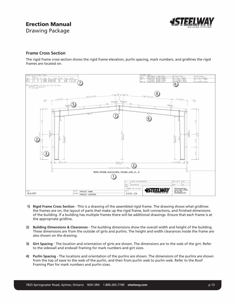
Frame Cross SectionThe rigid frame cross section shows the rigid frame elevation, purlin spacing, mark numbers, and gridlines the rigid frames are located on.
1) Rigid Frame Cross Section - This is a drawing of the assembled rigid frame. The drawing shows what gridlines the frames are on, the layout of parts that make up the rigid frame, bolt connections, and finished dimensions of the building. If a building has multiple frames there will be additional drawings. Ensure that each frame is at the appropriate gridline.
2) Building Dimensions & Clearances - The building dimensions show the overall width and height of the building. These dimensions are from the outside of girts and purlins. The height and width clearances inside the frame are also shown on the drawing.
3) Girt Spacing - The location and orientation of girts are shown. The dimensions are to the web of the girt. Refer to the sidewall and endwall framing for mark numbers and girt sizes.
4) Purlin Spacing - The locations and orientation of the purlins are shown. The dimensions of the purlins are shown from the top of eave to the web of the purlin, and then from purlin web to purlin web. Refer to the Roof Framing Plan for mark numbers and purlin sizes.
Erection ManualDrawing Package
1
3
2
2
5
4
6
6
7
7

7825 Springwater Road, Aylmer, Ontario N5H 2R4 1.800.265.7740 steelway.com p 14
5) Flange Brace Locations - Flange braces are shown on the roof and walls of the building at (FB) locations. Flange braces can be single sided indicated with a (1) or double sided (2). Flange brace marks are based on the size and length of the brace. Refer to the top left corner of the page for Flange brace thicknesses related to their marks.
6) Rigid Frame Member Mark Numbers - Rigid frame mark numbers for each member are shown on the drawing. The table in the top right corner describes the plate size each member is made of.
7) Rigid Frame Connections - The rigid frame splices are indicated on the drawing. The spice plate numbers coincide with the Splice Plate & Bolts table in the top left corner of the page. The table shows the splice mark, bolts and plate size. The quantity, type, diameter, and length of bolts are also shown for each splice plate connection. Ensure that the proper bolts are used as indicated.
Erection ManualDrawing Package

7825 Springwater Road, Aylmer, Ontario N5H 2R4 1.800.265.7740 steelway.com p 15
Endwall FramingThe Endwall Framing drawing shows the various building members for the endwalls, as well as the opening locations and sizes. The endwalls are identified by grid line number and as Left Endwall, Right Endwall. Framing elevations are oriented looking at the building from the outside.
1) Building Dimensions - The overall dimensions of the wall are measured from the outside face of girt to the
outside face of girt. These dimensions will match the out to out steel dimensions on the Anchor Bolt Plan.
2) Bay Spacing - These dimensions indicate the distance between the centre line of a column and the centre line of a column.
3) Girt Spacing - The location and orientation of girts are shown. The dimensions are to the web of the girt.
4) Framing Members - All wall framing members are shown and a mark number is given. These mark numbers coincide with the Member table on the top right of the page.
5) Factory Located Openings - All overhead doors are factory located. The dimensions to locate openings will be either from the outside of the girt to the edge of the opening, or from the centre of the column to the edge of the opening. The width and height of the opening are also shown on the drawing.
Erection ManualDrawing Package
1
1
3
2
5
4
4
6
7
8

7825 Springwater Road, Aylmer, Ontario N5H 2R4 1.800.265.7740 steelway.com p 16
6) Laps - These dimensions indicate the length that girts will lap. Ensure that the proper lap is at the right location.
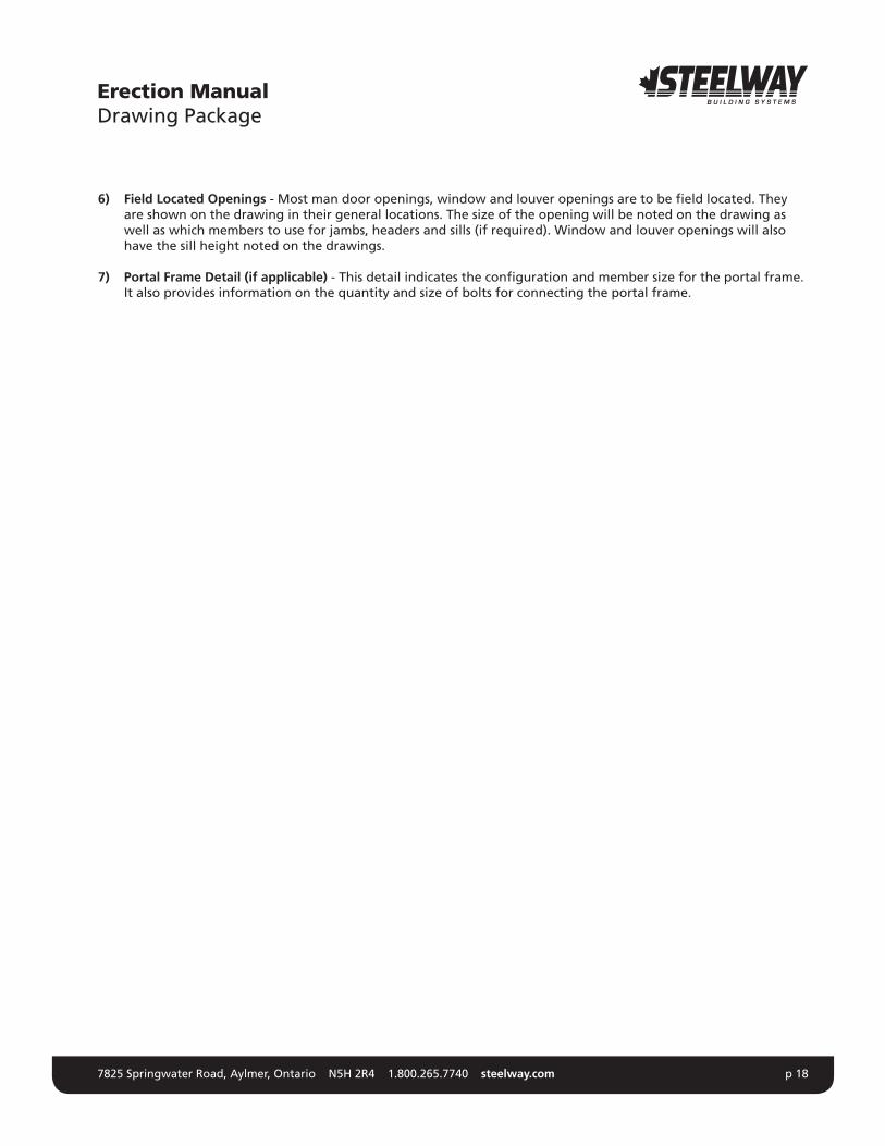
7) Field Located Openings - Most man door openings, window and louver openings are to be field located. They are shown on the drawing in their general locations. The size of the opening will be noted on the drawing as well as which members to use for jambs, headers and sills (if required). Window and louver openings will also have the sill height noted on the drawings.
8) Table - This table indicates the size, type and length of bolts to be used for the column and rafter connections. The location of the bolts is indicated by the part numbers of the connecting members. Ensure that the proper bolts are used as indicated.
Erection ManualDrawing Package

7825 Springwater Road, Aylmer, Ontario N5H 2R4 1.800.265.7740 steelway.com p 17
Sidewall FramingThe sidewall framing drawing shows the various building members for the sidewalls, as well as the opening locations and sizes. The sidewalls are identified by grid line number. Framing elevations are oriented looking at the building from the outside.
1) Building Dimensions - The overall dimensions of the wall are measured from the outside face of the girt to the outside face of the girt. These dimensions will match the out to out steel dimensions on the Anchor Bolt Plan.
2) Bay Spacing - These dimensions indicate the distance between the centre line of a column and the centre line of a column.
3) Girt Spacing - The location and orientation of girts are shown. The dimensions are to the web of the girt.
4) Framing Members - All wall framing members are shown and a mark number is given. These mark numbers coincide with the Member table on the top right of the page.
5) Girt Laps - These dimensions indicate the length that girts will lap. Ensure that the proper lap is at the right location.
Erection ManualDrawing Package
1
1
3
2
5
4
4
4
6
7
7825 Springwater Road, Aylmer, Ontario N5H 2R4 1.800.265.7740 steelway.com p 18
6) Field Located Openings - Most man door openings, window and louver openings are to be field located. They are shown on the drawing in their general locations. The size of the opening will be noted on the drawing as well as which members to use for jambs, headers and sills (if required). Window and louver openings will also have the sill height noted on the drawings.
7) Portal Frame Detail (if applicable) - This detail indicates the configuration and member size for the portal frame. It also provides information on the quantity and size of bolts for connecting the portal frame.
Erection ManualDrawing Package

7825 Springwater Road, Aylmer, Ontario N5H 2R4 1.800.265.7740 steelway.com p 19
Steelway is not responsible for the design or installation of the foundation. All soil preparation and foundation design must be prepared by a licensed engineer qualified for this work.
Site Preparation The efficient erection of a steel building hinges on the quality of the foundation installation. The foundation must be square, straight, and level. All dimensions shown on the Anchor Bolt Plan must be carefully observed. Locate the anchor bolts carefully, following the details provided. Use templates to hold the anchor bolts firmly in position so they will not settle or be knocked out of alignment before the concrete hardens.
The use of a transit and/or level is recommended when laying out the foundation. Measure the width and length on each side and from corner to corner of the building and each bay to ensure the layout is square. Installing the building components and getting the building straight and square will be much easier if the foundation is accurate.
Ensure that the foundation has had time to cure properly before attempting to erect the building.
Steelway expects foundation and anchor bolt installation to meet the requirements of CAN/CSA-S16-09. CISC Code of Standard Practice for Structural Steel, which is referenced by CAN/CSA-S16-09, specifies the acceptable tolerances for the anchor bolt placement in Section 7 (see also Appendix D). Anchor bolts must not vary from the dimensions shown on the Erection Drawings by more than the following
1) 1/8” (3mm) center to center of any bolt within an anchor bolt group, where an anchor bolt group is defined as the set of anchor bolts which receives a single fabricated steel shipping piece;
2) 1/4” (6mm) center-to-center of adjacent anchor bolt groups;
3) Maximum accumulation of 1/4” (6mm) per 100’ (30 480 mm) along the established column line of multiple anchor bolt groups, but not to exceed a total of 1” (25mm). The established column line is the actual field line most representative of the centers of the as-built anchor bolt groups along a line of columns;
4) 1/4” (6mm) from the center of any anchor bolt group to the established column line through that group.
Items 2, 3, and 4 also apply to offset dimensions, shown on the Erection Drawings, measured parallel and perpendicular to the nearest established column line for individual columns shown on the drawings to be offset from established column lines. Anchor bolts are to be set perpendicular to the bearing surface, threads protected and free of concrete, and nuts should run freely. Shear pockets are to be cleaned prior to steel erection.
Erection ManualFoundations/Squaring Methods
7825 Springwater Road, Aylmer, Ontario N5H 2R4 1.800.265.7740 steelway.com p 20
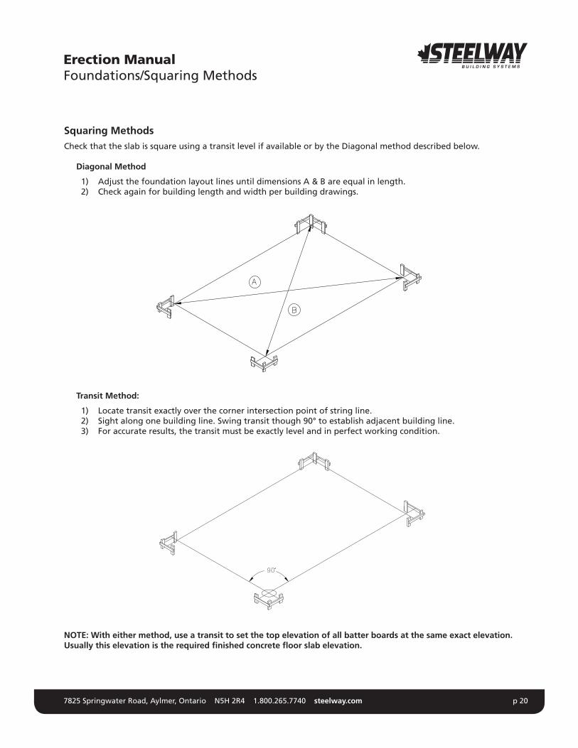
Squaring MethodsCheck that the slab is square using a transit level if available or by the Diagonal method described below.
Diagonal Method
1) Adjust the foundation layout lines until dimensions A & B are equal in length. 2) Check again for building length and width per building drawings.
Transit Method:
1) Locate transit exactly over the corner intersection point of string line. 2) Sight along one building line. Swing transit though 90° to establish adjacent building line. 3) For accurate results, the transit must be exactly level and in perfect working condition.
NOTE: With either method, use a transit to set the top elevation of all batter boards at the same exact elevation. Usually this elevation is the required finished concrete floor slab elevation.
Erection ManualFoundations/Squaring Methods
7825 Springwater Road, Aylmer, Ontario N5H 2R4 1.800.265.7740 steelway.com p 21
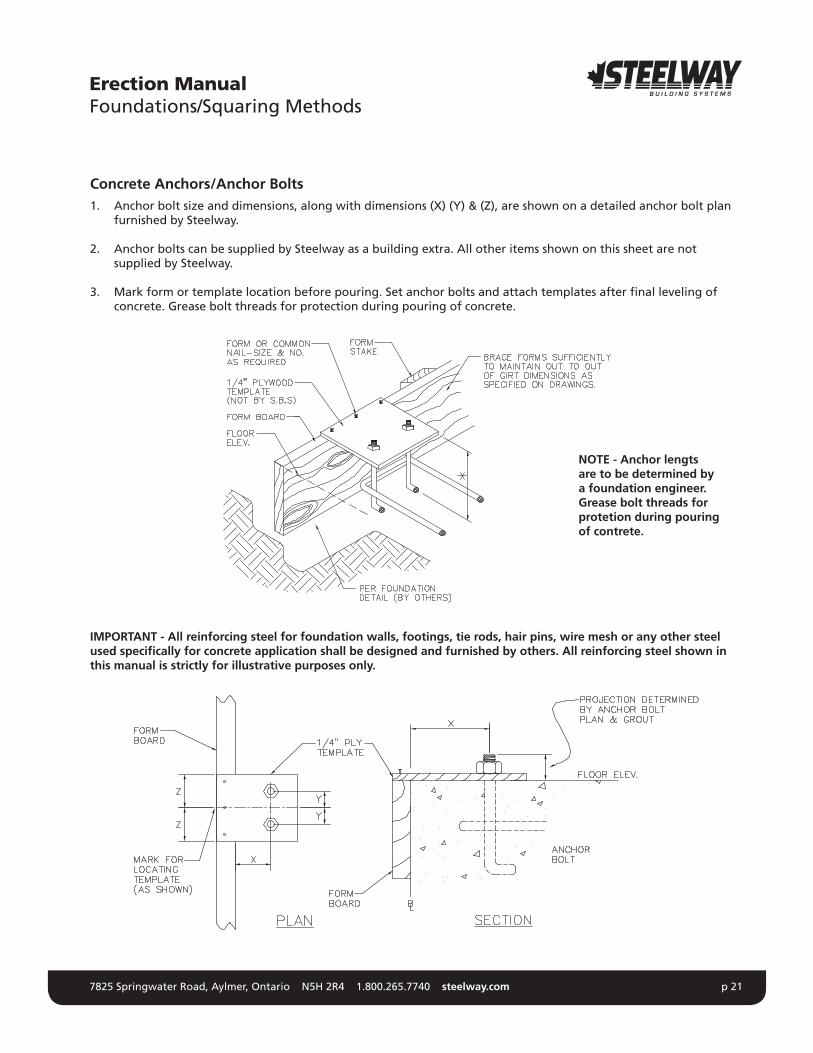
Concrete Anchors/Anchor Bolts 1. Anchor bolt size and dimensions, along with dimensions (X) (Y) & (Z), are shown on a detailed anchor bolt plan
furnished by Steelway.
2. Anchor bolts can be supplied by Steelway as a building extra. All other items shown on this sheet are not supplied by Steelway.
3. Mark form or template location before pouring. Set anchor bolts and attach templates after final leveling of concrete. Grease bolt threads for protection during pouring of concrete.
IMPORTANT - All reinforcing steel for foundation walls, footings, tie rods, hair pins, wire mesh or any other steel used specifically for concrete application shall be designed and furnished by others. All reinforcing steel shown in this manual is strictly for illustrative purposes only.
Erection ManualFoundations/Squaring Methods
NOTE - Anchor lengts are to be determined by a foundation engineer. Grease bolt threads for protetion during pouring of contrete.

7825 Springwater Road, Aylmer, Ontario N5H 2R4 1.800.265.7740 steelway.com p 22
Foundations/Squaring MethodsBe sure to check all foundation measurements including: overall size, elevation, level and squareness, anchor bolt placement and projection. Use a steel tape and transit and reference to a permanent benchmark. Check each dimension shown on the anchor bolt plan.
Double check ‘A’ (the inside bolt spacing) before placing concrete. (See anchor bolt plan for dimensions)
Also check the bolt alignment using a string. All anchor bolt placement tolerance is to meet the current S16.1 code.
Erection ManualFoundations/Squaring Methods

7825 Springwater Road, Aylmer, Ontario N5H 2R4 1.800.265.7740 steelway.com p 23
Tolerances on Anchor Bolt PlacementNOTE - These illustrations set out the tolerances and anchor bolt projection that the foundation is expected to meet.
Erection ManualFoundations/Squaring Methods
n
n-1
6
5
4
3
2
1

7825 Springwater Road, Aylmer, Ontario N5H 2R4 1.800.265.7740 steelway.com p 24
Arrival at the Building Site When fabrication is complete, shipment is made to the building site. All building components are carefully bundled, crated and inspected to prevent damage during transportation. The transportation company is responsible for delivering these components undamaged.
ReceivingWhen the shipment is received, check each item against the proper shipping document. If a shortage is discovered, have the transportation agent make a notation to that effect, on your bill. Then report to Steelway in writing, any shortages upon unloading.
Examine your shipment carefully for damage. If any damage is found, be sure the agent makes a damage notation on the bill before accepting it.
If damage is concealed until crating or packaging is removed, call your agent at once for an inspection and obtain an inspection memorandum covering concealed damage.
Unloading and Material Layout
As the building material is unloaded, it should be placed in and around the building site near the place where it will be used. While each job will vary according to the size or site conditions, the above layout typifies an arrangement which offers convenience and accessibility during assembly.
Rigid frame columns are laid in position for erecting. Roof beams are stacked for sub-assembly and are easily accessible for setting.
Erection ManualUnloading Material
1
1
1
1
1
1
1
1
3
33
3
3
3
3
33
2
2
5
5
4
6
1. Girt, Eave Struts and Purlins2. End Frames3. Main Frames
4. Hardware (clips, bolts screws etc.)5. Endwall Girts6. Foundation
Material Layout

7825 Springwater Road, Aylmer, Ontario N5H 2R4 1.800.265.7740 steelway.com p 25
Girts, purlins, eave member and braces are divided according to the requirements of each bay. Nested parts should be separated and blocked.
Endwalls are laid out for each end.
Small components (nuts and bolts, clips, sag rods, fasteners, etc.) are assembled in a given area and convenient to all parts of the building. To prevent any loss due to theft, these small components should be secured at the end of the working day. ***Mention crating***
Cladding and other components, which will not be used in the initial stage of erecting the steel, are placed to the outside on the boards and covered to protect them from the weather and contact with the ground.
Safety PrecautionsStay well in the clear of loads being lifted by machinery and keep hands and feet clear of moving loads.
Using a Spreader BarUse a spreader bar to lift panel crates that are longer than 25 feet. Panels should be lifted with slings that are specifically designed to lift light gauge panels. The spreader bar reduces the possibility of buckling long sheets as they are being lifted.
CORRECT INCORRECT
IMPORTANT - Roof panels or bundles are often located on the roof prior to installation (on roofs slopes of 2:12 or less).
This procedure can cause damage if the crates are located over unsupported areas. If the crates are to be located on the roof structure, the following blocking procedure must be adhered to: 1. Allstructuralmembers,flangebracing,rod/cablebracingandpurlinstabilizersmustbeinplace.Plumband
tighten bolts before blocking is installed, and bundles are placed on the roof. 2. Bundles should only be located directly over frames. Bundles should not be located on purlins at mid span. 3. Blocking should be installed between all purlins at the frames where crates are to be located. The length of
the blocking should equal the purlin spacing. 4. Remove the blocking after the panels are installed.
Erection ManualUnloading Material

7825 Springwater Road, Aylmer, Ontario N5H 2R4 1.800.265.7740 steelway.com p 26
UnloadingFor primary and secondary structural steel, the unloading equipment should be positioned at the pickup or balanced points of the load. The weight and shape of the load determines the pick-up points.
NOTE: NO ONE should be allowed to walk on materials stored on the ground as footprints can still be seen on the material after it has been erected. Time spent cleaning soiled materials could be better spent on erection.
Shop PrimerSteelway’s standard grey oxide primer provides temporary protection against rust during transportation and while the building is being erected. Our primer is not designed for long term exposure to the elements. It is the erector’s responsibility to protect the steel if it is to be stored on site for any length of time. Purlins and girts should be covered, and sloped to allow for water to drain off the material. Primary steel should be covered and safely stacked inanup-rightpositionWaterthatisallowedtopondonflangesorwebscancausetheprimertoliftandflakeoffthe steel over time. Steelway will not be held responsible for paint damaged by ponding water. It is the erector’s responsibility to touch up shop primer that has been damaged during erection.
StorageIMPORTANT: If panels are wet or damp uncrate immediately and restack so that air can circulate between them.
Recommended Jobsite Storage & Protection for Sheeting
1. Block above ground to keep water out. 2. Slope bundles for drainage. 3. Stack sheeting with spacers between bundles. 4. Cover with tarp or plastic to protect from rain or snow. 5. Tie down cover ends away from stack to permit air movement. Do not wrap under or restrict air movement.
Erection ManualUnloading Material

7825 Springwater Road, Aylmer, Ontario N5H 2R4 1.800.265.7740 steelway.com p 27
AssemblyMany erectors know that a man on the ground can work twice as efficiently as a man working in the air. It will help the builder if he can assemble as many components as possible while they are on the ground. Ground pre-assembly is safer and takes a lot less of the crew’s time and energy, especially tightening of High Strength bolts whenever possible.
Columns can be pre-assembled with clips, brace angles and other miscellaneous connections. The builder will have to decide on how much pre-assembly can be done depending on the size and type of job. Flange brace angles can also be loosely bolted to the rafter sections while they are on the ground. Post and beam endwall materials can also be laid out at each end of the building. They can be partially or fully pre-assembled for tilting up into place as a unit or unit sections. Girts, purlins, eave struts and door jamb bundles should be opened and divided along each side of the building according to the requirements of each bay. Wall and roof rods should be placed in their respective bays. (Turn the rod nuts down then back them off to clean the nut threads) Pre-assembling nuts, bolts and washers can also save time later.
Tips for Assembly
•Ifsheetingisnotappliedimmediatelythegirtsshouldbeblockedorropedtopreventgirtflutter •Walkingorclimbingongirtconnectionsintroducesseverestressesonthesteel.Therepairofcarelesslydamaged
material is always more costly than measures of prevention. •Priortoinstallation,notethepositioningforeachgirtlineshownonthedrawingsprovidedbySteelwayto
accommodate the framed openings. This is done to avoid erratic screw lines and stripped out screw holes in the sheets.
•Itisimportanttoalignthefaceofthebaseangleorbasegirtwiththegirtfacestoallowfortheproperalignment of the wall sheeting. Avoid setting the base angle inside of the concrete edge as panel dimples can occur when fasteners are driven.
•Initialallfinishedconnectionssoothersalsoknowthattheyhavebeenfinished. •Makesurethattherearenodamagedmaterialsonthestructurethatwouldrequiretheremovalofsheeting
to repair.
NOTESteelway does not supply or design the erection bracing required to erect the steel building system. The instructions in this guide are solely intended to represent the fact that erection bracing is required during erection, and are not to be interpreted as representing proper erection bracing configurations, components or anchorages.
CAN/CSA-S16-01, Section 29, and CISC Code of Standard Practice for Structural Steel, Section 7, require the use of erection bracing which can withstand all of the loads on the uncompleted structure, including wind, equipment, and equipment operation. The Erector is to ensure that there is an adequate margin of safety in the uncompleted structure. Erection bracing is to remain in place undisturbed as long as required for the safety and integrity of the structure.
Roof and wall panels are an integral part of the steel building system. Until the paneling is completely installed, the building cannot be considered fully braced. DO NOT REMOVE THE ERECTION BRACING UNTIL PANEL INSTALLATION IS COMPLETE.
Prepare a detailed plan for the erection bracing and the timing of its installation and removal before the erection commences. Take into account all loads that will be imposed on the building at the various phases or erection, including temporary piles of materials and the work of other trades.
Construction loads may be greater than the design loads required for the building by the building code and must be accounted for. For instance, the partially erected steel building can present more surface area to the wind than when the exterior panels have been fully installed, yet the strength of the building system may depend, in part, on
Erection ManualPrimary and Secondary Steel Erection
7825 Springwater Road, Aylmer, Ontario N5H 2R4 1.800.265.7740 steelway.com p 28
the bracing of the purlins and girts may need to be roped or blocked to prevent them from fluttering in the wind.Install the necessary erection bracing before each component is detached from the lifting equipment. To minimize crane time, attach erection bracing cables to the components before lifting and secure as soon as the components are in place.
Do not rely on the anchor bolts to temporarily secure columns ensuring erection. Ensure that the foundation and anchor bolts are suitable for any and all erection induced forces.
Frames having interior columns require special attention. Due to the additional support of the interior columns, the members are lighter than those of clear-span frames. These members are more apt to buckle during erection and require more care when lifting and bracing. Never leave the free end of an uncompleted frame without proper bracing.
Ensure that the structure is adequately braced at the end of each work day.
Erection ManualPrimary and Secondary Steel Erection

7825 Springwater Road, Aylmer, Ontario N5H 2R4 1.800.265.7740 steelway.com p 29
Step One
1. Erect mainframe columns starting at a braced bay and snug tight all anchor bolts. The top of all shims or leveling nuts used by the erector should be level at all four corners or the base plates. Check anchor bolt plan and erection drawings for special conditions.
2. Erect temporary bracing and all sidewall girts to mainframe columns before erecting rafters.
NOTE - All lifting devices are to be specifically designed to lift the various building components. Spreader bars and slings are to be used to prevent permanent deformation of all structural members. It is the erectors responsibility to determine the correct size and quantity of cranes.
For spans greater than 150’ clear, an alternate procedure should be considered.
CAUTION - Brace all framing properly during the day and overnight. Unexpected winds will bring inadequately braced framing down.
Erection ManualPrimary and Secondary Steel Erection
Temporary Column Bracing(Cable stregth and anchorage to be determined by the erector).

7825 Springwater Road, Aylmer, Ontario N5H 2R4 1.800.265.7740 steelway.com p 30
Step Two
1. Bolt rafter assembly together on the ground and tighten all high strength bolts using ‘Turn-of Nut’ method as specified under clause 23.4 CAN/CSA -Si 6.1 M94. Also see section 6.0 of this manual)
2. Lift rafter sections into place. Install all columns to rafter connection bolts using ‘Turn-of-Nut method. 3. Hold in place until this section is secured to columns and temporary bracing is tied off in both directions to
hold frame in place and reduce lateral movement.
CAUTION - Care must be taken not to twist the rafter or induce impact loads when lifting or setting the rafter into place.
Erection ManualPrimary and Secondary Steel Erection
Temporary Rafter Bracing(Brace rafter at ridge, each interior column of every other permanent roof bracing panel point in both diretions).

7825 Springwater Road, Aylmer, Ontario N5H 2R4 1.800.265.7740 steelway.com p 31
Step Three
1. Raise second haunch and rafter beam frame section into place. 2. Hold in place until this section is bolted to columns and lead purlins have been attached. A minimum of both
eave and ridge purlins, plus intermediate purlins at bracing panel points must be installed.
Erection ManualPrimary and Secondary Steel Erection
Lead Purlins
TemporaryColumn Bracing(Both directions).

7825 Springwater Road, Aylmer, Ontario N5H 2R4 1.800.265.7740 steelway.com p 32
Step Four
1. Bolt in place all remaining purlins of the braced bay. 2. Installpurlinstabilizersandflangebracesasshownontheerectiondrawings,permanentrodbracingis
loosely installed. 3. Square and plumb braced bay, using a transit or laser and permanent rod bracing snugged down.
NOTE - Rigid frames are NOT designed to resist any lateral loads applied in the direction indicated. Only temporary and permanent bracing can resist these loads.
Erection ManualPrimary and Secondary Steel Erection
TemporaryColumn Bracing(Both diretions).

7825 Springwater Road, Aylmer, Ontario N5H 2R4 1.800.265.7740 steelway.com p 33
Step Five
1. Locate the transit as shown above (in this particular case slightly to the left of the first rigid frame). 2. Make sure the transit is perfectly level. 3. RotatethetransituntilyougettheexacttapereadingsatpointsAandB(basecolumn,outsideflange - see detail). 4. Lock horizontal rotation of the transit. 5. Adjust rod bracing until the tape reading at points A and B is obtained at all points indicated on above sketch.Takeallreadingsfromtheoutsideedgeoftheflange(adjustreadingsforvaryingflangewidths along the frame).
Erection ManualPrimary and Secondary Steel Erection
A
B
TemporaryRafter Bracing
Transit Location
Read with transit or laser

7825 Springwater Road, Aylmer, Ontario N5H 2R4 1.800.265.7740 steelway.com p 34
Step Six
1. Proceed with the erection of the remaining frames and post and beam endwalls. 2. If the building bay does not exceed the number of bays shown in the sketch, only eave members and lead
purlins may be used to stabilize frames, and post and beam endwalls. Erect next braced bay (if applicable) before proceeding to erect the remaining frames.
Erection ManualPrimary and Secondary Steel Erection
Lead Purlins
Temporary Bracing

7825 Springwater Road, Aylmer, Ontario N5H 2R4 1.800.265.7740 steelway.com p 35
Step Seven
1. Completeerectionofallbuildingcomponents,ensuringthatallsecondarystructuralboltsandflangebraceshave been installed.
2. Square and plumb entire building again before proceeding to point 3. Make periodic alignment checks and adjustments throughout erecting the balance of the structural system, based on this benchmark bay. This will make all succeeding connections easier. The temporary construction bracing should still be in place and tight.
3. Note that after the completion of all secondary framing in one end bay, attachment of roof panels may commence with the completion of the remaining components.
Alternate Purlin Erection ProcedureFollow step one & two as shown previously.
Erection ManualPrimary and Secondary Steel Erection

7825 Springwater Road, Aylmer, Ontario N5H 2R4 1.800.265.7740 steelway.com p 36
Alternate Step TwoNOTE - All lifting devices are to be specifically designed to lift the various building components. Spreader bars and slings are to be used to prevent permanent deformation of all structural members. Four cranes may be required depending on total span and weight of assembled sections. It is the erectors responsibility to determine the correct size and number of cranes.
IMPORTANT - Both temporary and permanent bracin gare critical both for safety and to prevent excessive twisting and damage of the steel during erection.
CAUTION - CARE MUST BE TAKEN NOT TO TWIST RAFTER OR INDUCE IMPACT LOADS WHEN LIFTING OR SETTING RAFTER INTO PLACE.
1. Starting at the braced bay, bolt both rafter assemblies together on the ground and tighten all high strength
bolts using ‘Turn-of-Nut’ method as specified under clause 23.4 CAN/CSA-S16.1 M94 (also section 6.0 of this manual).Standraftersectionsuprightandboltallpurlins,stabilizers,flangebracesandpermanentbracingonthe ground.
2. Lift entire assembly into place. Install all columns to rafter connection bolts using ‘Turn-of-Nut method. 3. Hold in place both rafter sections until temporary bracing is tied off. Temporary bracing should still be used to
reduce lateral movement.
Erection ManualPrimary and Secondary Steel Erection
Temporary Rafter Bracing(Brace rafter at ridge, each interior column and minimum of every other permanent roof bracing panel point).

7825 Springwater Road, Aylmer, Ontario N5H 2R4 1.800.265.7740 steelway.com p 37
Alternate Step Three
1. Install both eave purlins and every other purlin starting at braced bay. 2. Square and plumb braced bay. 3. Erect next frame and install every other purlin in an alternate fashion as shown above.
Alternate Step Four 1. Install remaining lapped purlins once all frames have been erected. 2. Installpurlinstabilizersandflangebracesasshownonerectiondrawings.
Erection ManualPrimary and Secondary Steel Erection
Temporary Bracing(as per building erector).
7825 Springwater Road, Aylmer, Ontario N5H 2R4 1.800.265.7740 steelway.com p 38
Basic Bolting InstructionsThis section is to provide the erector with the basic bolting requirements needed to erect the steel components supplied by Steelway Building Systems. It should be noted that the erector is responsible for using safe and correct building erection procedures. It is also the erector’s responsibility not to apply any excessive twisting or lateral movement to any of the connections since these types of forces are NOT considered in design.
It should also be noted that Steelway recommends only the ‘Turn-of-Nut’ method as specified under clause 23.4 CAN/CSA-S16.1-M94 and section 6.0 of this manual. The ‘Job Inspection Torque’ table last appeared in the 1978 edition of S16.1. All other editions (1984, ‘89, ’94) no longer use bolt torque values.
The reasons for this are as follows: •Therelationshipbetweenbolttorqueandbolttensionisnotconstant,norpredictable •Thedesignobjectiveistension,nottorque. •Torquedependsonfrictionbetweenthenutthreadsandboltthreads.
Friction is a function of: •Threadfitandclearances •Threadlubrication •Manufacturingprocesses •Boltcoatings(zinc,cadmium,etc.) •Thelengthoftimeboltcontainersareopenedandexposedtotheelements. •Timedifferencesbetweenuseofthefirstboltsfromthecontainerandthelastbolts •Whetherwashersareusedornot
Therefore, you cannot rely on the site torque values to indicate correct bolt tension values.
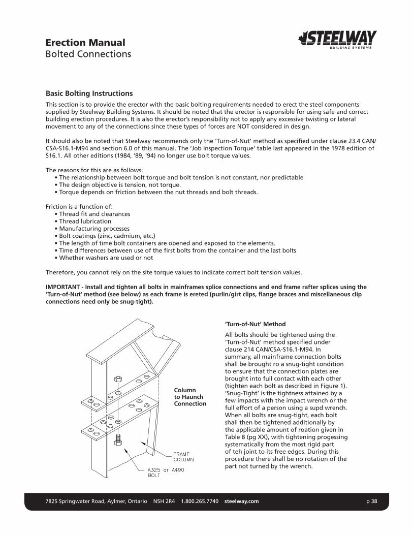
IMPORTANT - Install and tighten all bolts in mainframes splice connections and end frame rafter splices using the ‘Turn-of-Nut’ method (see below) as each frame is ereted (purlin/girt clips, flange braces and miscellaneous clip connections need only be snug-tight).
Erection ManualBolted Connections
‘Turn-of-Nut’ Method
All bolts should be tightened using the ‘Turn-of-Nut’ method specified under clause 214 CAN/CSA-S16.1-M94. In summary, all mainframe connection bolts shall be brought ro a snug-tight condition to ensure that the connection plates are brought into full contact with each other (tighten each bolt as described in Figure 1). ‘Snug-Tight’ is the tightness attained by a few impacts with the impact wrench or the full effort of a person using a supd wrench. When all bolts are snug-tight, each bolt shall then be tightened additionally by the applicable amount of roation given in Table 8 (pg XX), with tightening progessing systematically from the most rigid part of teh joint to its free edges. During this procedure there shall be no rotation of the part not turned by the wrench.
Columnto HaunchConnection
7825 Springwater Road, Aylmer, Ontario N5H 2R4 1.800.265.7740 steelway.com p 39
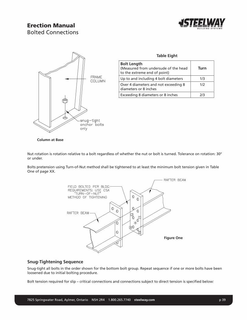
Nut rotation is rotation relative to a bolt regardless of whether the nut or bolt is turned. Tolerance on rotation: 30° or under.
Bolts pretension using Turn-of-Nut method shall be tightened to at least the minimum bolt tension given in Table One of page XX.
Snug-Tightening Sequence Snug-tight all bolts in the order shown for the bottom bolt group. Repeat sequence if one or more bolts have been loosened due to initial bolting procedure.
Bolt tension required for slip – critical connections and connections subject to direct tension is specified below:
Erection ManualBolted Connections
Bolt Length(Measured from undersude of the head to the extreme end of point)
Turn
Up to and including 4 bolt diameters 1/3
Over 4 diameters and not exceeding 8 diameters or 8 inches
1/2
Exceeding 8 diameters or 8 inches 2/3
Table Eight
Column at Base
Figure One
7825 Springwater Road, Aylmer, Ontario N5H 2R4 1.800.265.7740 steelway.com p 40
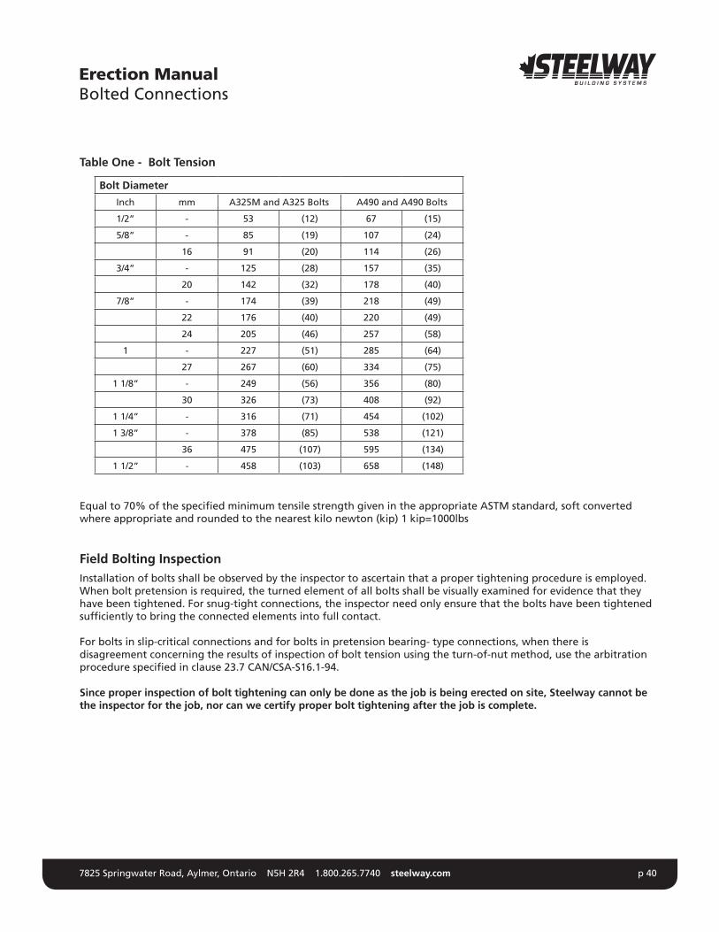
Table One - Bolt Tension
Equal to 70% of the specified minimum tensile strength given in the appropriate ASTM standard, soft converted where appropriate and rounded to the nearest kilo newton (kip) 1 kip=1000lbs
Field Bolting InspectionInstallation of bolts shall be observed by the inspector to ascertain that a proper tightening procedure is employed. When bolt pretension is required, the turned element of all bolts shall be visually examined for evidence that they have been tightened. For snug-tight connections, the inspector need only ensure that the bolts have been tightened sufficiently to bring the connected elements into full contact.
For bolts in slip-critical connections and for bolts in pretension bearing- type connections, when there is disagreement concerning the results of inspection of bolt tension using the turn-of-nut method, use the arbitration procedure specified in clause 23.7 CAN/CSA-S16.1-94.
Since proper inspection of bolt tightening can only be done as the job is being erected on site, Steelway cannot be the inspector for the job, nor can we certify proper bolt tightening after the job is complete.
Erection ManualBolted Connections
Bolt Diameter
Inch mm A325M and A325 Bolts A490 and A490 Bolts
1/2” - 53 (12) 67 (15)
5/8” - 85 (19) 107 (24)
16 91 (20) 114 (26)
3/4” - 125 (28) 157 (35)
20 142 (32) 178 (40)
7/8” - 174 (39) 218 (49)
22 176 (40) 220 (49)
24 205 (46) 257 (58)
1 - 227 (51) 285 (64)
27 267 (60) 334 (75)
1 1/8” - 249 (56) 356 (80)
30 326 (73) 408 (92)
1 1/4” - 316 (71) 454 (102)
1 3/8” - 378 (85) 538 (121)
36 475 (107) 595 (134)
1 1/2” - 458 (103) 658 (148)

7825 Springwater Road, Aylmer, Ontario N5H 2R4 1.800.265.7740 steelway.com p 41
Other Field Connection Notes 1. Minimumboltlengthrequiresthatboltsneedonlybeflushwiththeoutsidefaceofthenutaftercompleting
the appropriate tightening method. 2. The erector should ensure that the proper bolts have been installed in the correct location. The following
markings should be observed on all high-strength bolts and nuts.
Erection ManualBolted Connections
7825 Springwater Road, Aylmer, Ontario N5H 2R4 1.800.265.7740 steelway.com p 42
Sheeting & TrimThe owner’s acceptance of any building depends on its finished appearance. Sheeting, trim and accessories are the most conspicuous elements of construction and must be installed with the greatest of care.
It is recommended that the wall sheeting be installed first as wall panels lend a high degree of rigidity to an incomplete structure.
Before sheeting is installed:
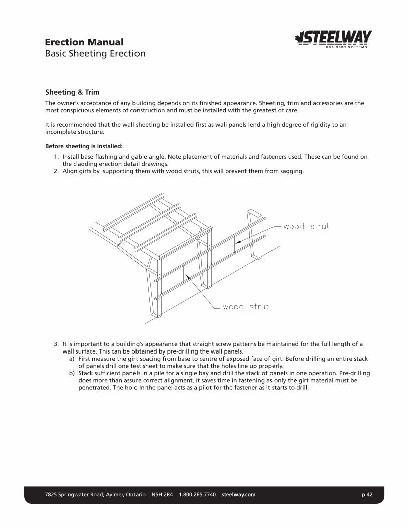
1. Installbaseflashingandgableangle.Noteplacementofmaterialsandfastenersused.Thesecanbefoundonthe cladding erection detail drawings.
2. Align girts by supporting them with wood struts, this will prevent them from sagging.
3. It is important to a building’s appearance that straight screw patterns be maintained for the full length of a wall surface. This can be obtained by pre-drilling the wall panels.
a) First measure the girt spacing from base to centre of exposed face of girt. Before drilling an entire stack of panels drill one test sheet to make sure that the holes line up properly.
b) Stack sufficient panels in a pile for a single bay and drill the stack of panels in one operation. Pre-drilling does more than assure correct alignment, it saves time in fastening as only the girt material must be penetrated. The hole in the panel acts as a pilot for the fastener as it starts to drill.
Erection ManualBasic Sheeting Erection
7825 Springwater Road, Aylmer, Ontario N5H 2R4 1.800.265.7740 steelway.com p 43
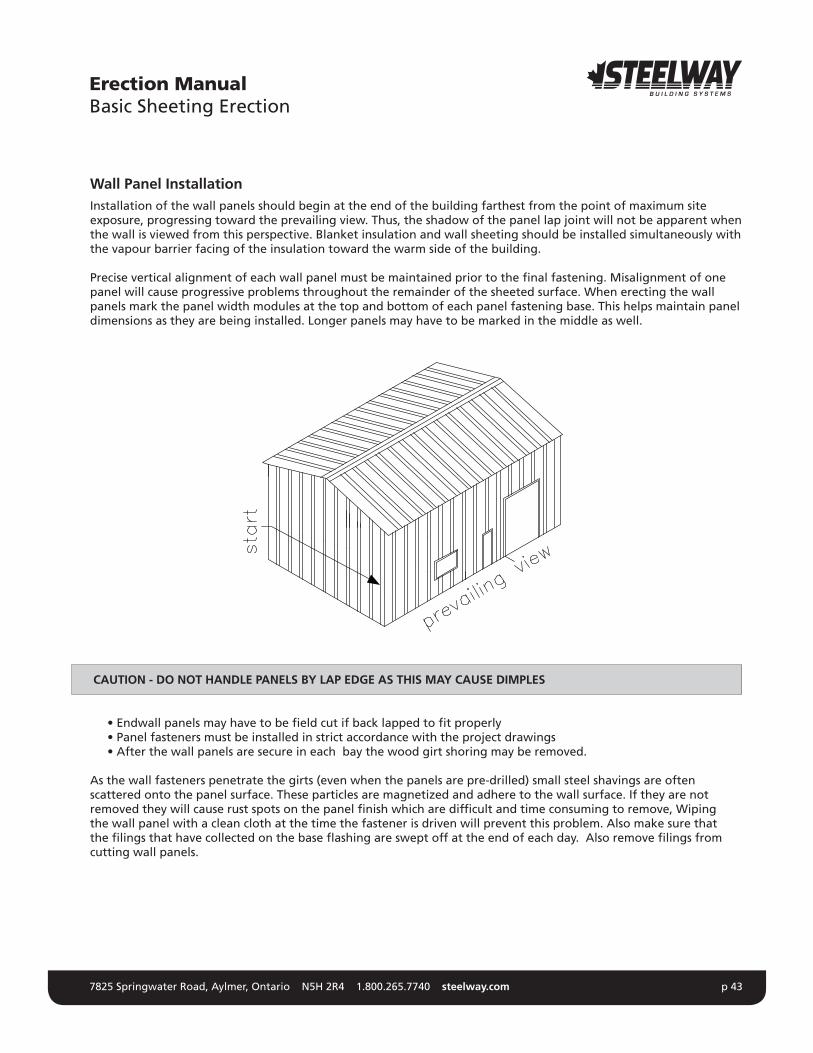
Wall Panel InstallationInstallation of the wall panels should begin at the end of the building farthest from the point of maximum site exposure, progressing toward the prevailing view. Thus, the shadow of the panel lap joint will not be apparent when the wall is viewed from this perspective. Blanket insulation and wall sheeting should be installed simultaneously with the vapour barrier facing of the insulation toward the warm side of the building.
Precise vertical alignment of each wall panel must be maintained prior to the final fastening. Misalignment of one panel will cause progressive problems throughout the remainder of the sheeted surface. When erecting the wall panels mark the panel width modules at the top and bottom of each panel fastening base. This helps maintain panel dimensions as they are being installed. Longer panels may have to be marked in the middle as well.
CAUTION - DO NOT HANDLE PANELS BY LAP EDGE AS THIS MAY CAUSE DIMPLES
•Endwallpanelsmayhavetobefieldcutifbacklappedtofitproperly •Panelfastenersmustbeinstalledinstrictaccordancewiththeprojectdrawings •Afterthewallpanelsaresecureineachbaythewoodgirtshoringmayberemoved.
As the wall fasteners penetrate the girts (even when the panels are pre-drilled) small steel shavings are often scattered onto the panel surface. These particles are magnetized and adhere to the wall surface. If they are not removed they will cause rust spots on the panel finish which are difficult and time consuming to remove, Wiping the wall panel with a clean cloth at the time the fastener is driven will prevent this problem. Also make sure that thefilingsthathavecollectedonthebaseflashingaresweptoffattheendofeachday.Alsoremovefilingsfromcutting wall panels.
Erection ManualBasic Sheeting Erection

7825 Springwater Road, Aylmer, Ontario N5H 2R4 1.800.265.7740 steelway.com p 44
Trim InstallationThe trim (installed simultaneously or right after the wall panels) has an enormous impact on the appearance of a building. Trims can easily be damaged by mishandling. If the trim is not true it detracts from the final appearance of thebuilding.Trims,flashingsandclosuresarefastenedandsealedasindicatedbyprojectdrawings.Onceagainpre-assemble as many trims as possible on the ground.
Roof Sheeting InstallationSheeting the roof is the single most important part in the erection of a structure. The roof must protect the building interior for many years.
As with the walls, roof sheets and insulation are installed simultaneously. All sheets should be positioned as indicated by the project drawings. Manufacturer’s instructions for eave, gable and ridge detailing should be followed closely. It is imperative that the roof panel extend past the eave trim by 2” or more. If the panel does not extend 2 or more inches past the eave trim winter roof water will run down the trim and the wall forming large icicles. The ice is unsightly and may damage the building. Care must be taken with the alignment of opposite sloped panel ribs for integrity of the ridge condition. If possible, lay out the roof panels so that the lap joint is on the leeward side of the most severe weather direction. This will reduce the possibility of a wind driven rain leak.
The builder is supplied with three weapons to prevent roof leaks. They are Tape sealant, tube caulking & closure strips. The proper application of each is very important. Follow the manufacturer’s recommendation for sealer, closure and fastener placement. Sealants should be installed during the erection of the lap sheet (i.e. on StormSeal roofs or liners). If the tape is installed too far in advance it can dry out or collect dirt, both of which could interfere with the sealing of the metal sheets. To ensure a tight seal, wipe the sheets with a rag to remove any oil, dirt or moisture.
Erection ManualBasic Sheeting Erection

7825 Springwater Road, Aylmer, Ontario N5H 2R4 1.800.265.7740 steelway.com p 45
CAUTION - NEVER USE AN UNFASTENED PANEL AS A WORK PLATFORM
A tape sealant should not be stretched during application. Remember to remove the release paper just prior to lapping the sheets. The end result of an incorrect installation will be a faulty lap seal and a costly leak.
Tube caulking should be used as necessary in accordance with sound erection practice.
Exerciseextremecautionwhenwalkingoninstalledroofpanels.Rooftrafficmustbeconfinedtopanelflatspreferably at the purlin line. Never walk or stand on the major panels ribs, this not only illustrates poor erection practice but it also opens up the lap joint and destroys the weather tightness of the roof. Never apply a concentrated single force to any major corrugation for any reason. Use walk boards to distribute loads over two or more corrugations.
It is imperative that drill filings be swept from the roof at the end of each work day. Drill shavings, either from saw cuts or drilling and fastening operations, may become embedded in the roof coating and within a matter of hours rust can develop. This rust could eventually run off of the roof and stain the wall finish as well.
There are many choices available to building owner’s today, in both roof systems and fastening devices. Each has its own merit and impact upon appearance, insurance requirements, life cycle value and cost. Most utilize sheet metal fasteners in various locations and capacities. Proper installations of these fasteners can only be accomplished with the proper equipment.
AccessoriesAccessories are chosen for their function and appearance. Most become integrated into the general building appearance. For this reason they must be installed with the same care and attention as the sheeting and trim. Accessory items typical to many structures include: framed openings, personal or service doors, skylights and wall lights, interior treatments, ventilation devices, overhangs and facia systems. Recheck the erection drawings for the location of each accessory and be sure to follow the manufacturer’s instructions explicitly for installation
InspectionA thorough inspection of the entire facility should be made by the owner prior to the owner’s final acceptance tour. All necessary corrections and adjustments should be made at this time. Things to look for should include: •theintegrityofthestructuralandsheetmetalconnections •missingcomponents •damagedcomponents •accessoriesoperatingproperly •marredfinishes
NOTE - A Preventative Maintenance Manual can be found on Steelway’s website at www.steelway.com.
Erection ManualBasic Sheeting Erection
7825 Springwater Road, Aylmer, Ontario N5H 2R4 1.800.265.7740 steelway.com p 46
Finally, the job site should be left in a condition that would satisfy you if you were the owner. A littered site detracts from the appearance of a newly completed building. No job site should be considered complete until all construction debris is cleaned up.
A clean, well organized job site also promotes safety work habits among construction workers. Safety cannot be stressed enough Workmen should be trained to use the proper safety equipment and procedures. Proper safety gear for the specific job should be enforced at all times. Safety cannot be solicited through a booklet, a rule, or a program. It is embodied in awareness, responsibility, commitment, training, and supervision.
“Safety is the best insurance for keeping everyone in business.”
Steelway hopes that these tips will help your erection jobs move more smoothly and result in the best constructed buildings possible. These buildings will be a credit to the industry and continue the evolution that has made metal buildings a major force in construction today.
Erection ManualConclusion
7825 Springwater Road, Aylmer, Ontario N5H 2R4 1.800.265.7740 steelway.com p 47
Accessory A building product that supplements the building structure and coverings such as door, window, skylight ventilator, etc.
Anchor Bolts Bolts used to anchor structural members to the foundation.
Anchor Bolt Plan A plan of the foundation showing all dimensions and sections required to properly locate and set all anchor bolts, including projection above concrete, recesses, etc.
Base Angle An angle secured to the foundation and used to attach the bottom of the wall paneling.
Base Channel A channel secured to the foundation and used to attach the bottom of the wall paneling.
Base Flashing A Flashing at the base of the wall panels used to shed water away from the building.
Base Plate A plate attached to the bottom of a column that rests on a foundation and is secured by anchor bolts.
Bay The space between the main frames measured parallel to the sidewall.
Beam A structural member, usually horizontal, that is subject to loads perpendicular to its length.
Bearing Clip The clip angle used to bolt secondary members to the main frames.
Bill of Material A list of components used for fabrication, shipping, receiving and accounting purposes.
Braced Bay A bay in a building which contains bracing.
Brace Rods Rods used on roof and sidewalls of some buildings to transfer wind, seismic, and lateral crane forces to the foundation.
Bracing Building components used in roofs and walls to transfer loads to the foundation. Also used to plumb and square buildings but not designed to replace erection bracing.
Bracing Tier A configuration of structural cross (X) members and struts.
Bracket A structural support projecting from a wall or column to another structural member. Examples: canopy brackets, lean-to brackets and crane runway brackets.
Bridge Crane A load lifting system consisting of a hoist that moves laterally on a bridge that in turn moves longitudinally on a runway made of beams and rails.
Building A structure forming an open, partially enclosed, or enclosed space constructed by a planned process of combining materials and components to meet specific conditions of use.
Building Length The dimension of the building, measured perpendicular to the main framing, between endwall steel lines.
Building Width The dimension of the building, measured parallel to the main framing, between sidewall steel lines.
Bypass A roof or wall framing system where the purlins or girts are completely outside theflangesoftheraftersorcolumns.
C.S.S.B.I. Canadian Sheet Steel Building Institute.
C.W.B. Canadian Welding Bureau.
Erection ManualGlossary of Terms

7825 Springwater Road, Aylmer, Ontario N5H 2R4 1.800.265.7740 steelway.com p 48
Cable Brace Cables used as the primary bracing method for the roof and sidewalls. These cables transfer wind and seismic forces to the foundation.
Cable Grip A helically formed high-strength-steel wire component used to connect a steel brace cable to an eyebolt or similar hardware.
Camber Curvatureofaflexuralmemberintheplaneofitswebbeforeloading.
Canopy A projecting roof system that is supported and restrained at one end only.
Cantilever A building component, typically a beam or rafter, which extends beyond its support so that one or both ends are not supported.
Capillary Action The action that causes movement of liquids when in contact with two closely adjacent surfaces such as panel sidelaps.
Caulk To seal and make weather-tight joints, seams, or voids by filling with a waterproofing compound or material. Also, the sealing material used.
“Cee” Section A member cold formed from sheet steel in the shape of a block “C” that may be used either singly or back to back. Also known as a light gauge channel.
Clear-Span Frame A rigid frame having no interior columns.
Clip A plate or angle used to fasten two or more members together.
Closure/Foam Closure Aresilientstripoffoamorneoprene,flatononesideandformedtothecontourof ribbed panels on the other side, used to close openings created when joining metalpanelstoflashings.
Column A main member used in a vertical position on a building to transfer loads to the foundation.
Component A part used in the building system.
Corner Trim Apreformedflashingtoclosetheintersectionofsidewallandendwallpanels.
Crane A machine designed to move material by means of a hoist.
Crane Beam The member that supports a crane rail. Supports may be columns or rafters depending on the type of crane system. On under-slung bridge cranes, the runway beam also acts as the crane rail.
Curb Araisededgeonaconcretefloorslaborroofaccessory.
Downspout A conduit used to carry water from the gutter of a building.
Drip Flashing A Flashing used at the top and bottom of windows and doors to shed water away from the building.
Eave The line along the sidewall formed by the intersection of the roof and wall steel lines.
Eave Extension An extension of the roof beyond the sidewall (eave) of the building.
Eave Height Theverticaldimensionfromfinishedfloortotheeave.
Eave Strut A structural member located at the eave of a building that supports roof and wall paneling.
Eave Trim A trim at the eave of the building.
End Bay The bays adjacent to the endwalls of a building.
End Frame A frame in the endwall of a building.
Erection ManualGlossary of Terms

7825 Springwater Road, Aylmer, Ontario N5H 2R4 1.800.265.7740 steelway.com p 49
Endwall The exterior edge of the building that is parallel to the main frames of the building.
Endwall Column A vertical member located at the endwall of a building, which supports the girts. In post and beam endwalls, the endwall columns also support the endwall rafter.
Endwall Rafter A structural beam located at the endwall supporting roof purlins.
Erection The on-site assembling of prefabricated components to form a complete structure.
Erection Bracing Bracing used and supplied by the erector during construction to hold the building components in position until the building is capable of supporting itself.
Erection Drawings Plans and erection instructions which identify all individual parts in sufficient detail to permit the proper erection and installation of the metal building system furnished by the manufacturer.
Expandable Endwall A building endwall designed to support a future expansion of the building length.
Expansion Joint A break or space in construction to allow for expansion and contraction of the materials used in the structure.
Facade A decorative band of panels or other materials at or around the perimeter of the roof.
Fascia A decorative trim or panel projecting from the face of a wall.
Field The “job site”, “building site” or general market area.
Finished Floor Elevation Thetheoreticalelevationofthesurfaceofthegroundfloorconcreteslab. Used as a reference elevation for the building.
Flange Brace Abracingmemberusedtoprovidelateralsupporttotheflangeofa structural member.
Flashing Light gage materials used to close and finish roof transitions, roof openings and wall openings.
Flush (Purlins/Girts) Arooforwallframingsystemwheretheoutsideflangesofthepurlinsorgirtsareflushwiththeoutsideflangesoftheraftersorcolumns.
Foundation The substructure that supports a building or other structure.
Frame See Framing.
Framed Opening Framework which surrounds an opening in the wall or roof of a building.
Framed Opening Trims Theflashingsandtrimsusedtofinishframedopenings.
Framing The primary and secondary members (columns, rafters, girts, purlins, bracing, etc.) which are assembled to make up the skeleton of a structure to which the panels are to be attached.
Gable The triangular portion of the endwall from the level of the eave to the ridge of the roof.
Gable Angle An angle that caps off the gable end of the building to allow for panels to be screwed.
Gable Extension An projection of the roof beyond the endwall of the building.
Gable Trim A Flashing designed to close the opening between the roof and endwall panels.
Girt A horizontal structural member that is attached to sidewall or endwall columns and supports wall paneling.
Erection ManualGlossary of Terms

7825 Springwater Road, Aylmer, Ontario N5H 2R4 1.800.265.7740 steelway.com p 50
Grade The term used when referring to the ground elevation around a building.
Grout A non-shrinking mixture of cement, sand and water used to fill cracks and cavities. Often used under base plates or levelling plates to obtain uniform bearing surfaces.
Gusset A steel plate used to reinforce or connect structural elements.Gutter A sheet metal channel installed at an eave, valley, or parapet for the purpose of
carrying water from the roof to the downspouts.
Haunch The intersection of a rigid frame column and rafter at the eave.
Header The horizontal framing member located at the top of a framed opening.
High-Lift Door An overhead door that is raised vertically as high as possible before folding away from the wall.
Hip The line formed where two adjacent sloping planes of a roof meet.
Ice Dam A build-up of ice, which forms a dam on the roof covering along the eave of the building.
Interior Column A column in a rigid frame which is located between the sidewall columns and provides support to the rigid frame rafter(s).
“J” Trim A J-shaped trim used to cover panel edges and ends at doors, windows, soffits, interior corners, etc.
Jack Beam A beam used to support another beam or rafter and eliminate a column support.
Jamb A vertical framing member at the side of a framed opening.
Joist Ahorizontalstructuralmemberthattransfersloadfromthefloororroofpanelstothe beams or rafters.
Knee See Haunch.
Lean-To A building, normally having a monoslope roof, which is partially supported on one side by another structure.
Light Gauge Generally, steel having a thickness between 8ga. and 18ga. Also, a term used to describe the secondary steel framing on a building.
Light-Transmitting Panels See Translucent Panels.
Liner Sheet metal panels, normally applied to the inside face of the purlins and/or girts, to provide an interior finish. In the case of a thermal roof or wall, the panel is applied to the outside face of the purlins and girts.
Masonry Anything constructed of granular materials such as brick, concrete block, ceramic block, and concrete.
Mastic Caulking or sealant furnished in rolls.
Mezzanine Anintermediatelevelbetweenfloorandceilingoccupyingapartialareaofthefloorspace.
Mill Section Steel sections (angles, channels, S sections, W sections, etc.) having standard dimensions and properties, which are formed by rolling mills while the steel is in a semi-molten state.
Monoslope A building having a roof sloping in one direction only. Used to designate a building that has a single-slope roof with two or more independent columns.
Multi Span Frame A Rigid Frame having interior columns.
Erection ManualGlossary of Terms

7825 Springwater Road, Aylmer, Ontario N5H 2R4 1.800.265.7740 steelway.com p 51
NBC National Building Code.
Nibbler An electric hand tool used to cut sheet steel.
Offset (Purlins/Girts) Arooforwallframingsystemwheretheoutsideflangesofthepurlinsorgirtsareoutsidetheflangesoftheraftersorcolumnsbyadistancelessthanthedepthofthe purlins or girts. Standard offset is 1” (25mm).
Overhead Door A door consisting of horizontally hinged sections, equipped with hardware and tracks that roll the door into an overhead position clear of, and immediately above, the door opening.
Packing List A list that calls out by quantity and part number each assembly or piece of material to be shipped for a building.
Panel (Roof/Wall) A thin (30ga. to 22ga.) sheet of steel having various profiles, used to cover the roof or wall of a building. The panel provides protection from the elements, rigidity for the building system, and aesthetic appeal.
Parapet Thatportionoftheverticalwallofabuildingthatextendsabovetheroofline at the intersection of the wall and roof.
Part Number A unique part identification. Also called a mark number or piece mark.
Partition An interior wall.
Peak The uppermost point of the gable.
Peak Sign A sign attached to the peak of the building at the endwall showing the building manufacturer.
Pinned Connection A connection between building components that is meant to provide support without preventing the rotation of the connected component(s). Also known as a simple connection.
Pitch See Roof Slope. Also, the distance between holes or bolts, measured parallel to the centerline, or web, of a member.
Ponding The gathering of water in low or depressed areas on a roof.
Portal Frame A Rigid Frame configuration designed to brace a building system where X-bracing is not permitted.
Post and Beam Endwall A structural system consisting of a series of rafters supported by columns. Used as the end frame of a building.
Pre-Painted Coil Coil steel that receives a paint coating prior to the forming operation.
Primary Eave Trim Aflashingusedtocloseofftheintersectionoftheroofandsidewallexteriorpanels. Provides a smooth, continuous surface onto which the roof panels are sealed.
Primary Members The main load-carrying members of a structural system, including columns, rafters, and beams.
Primer The initial coat of paint applied in the shop to the structural framing of a building for protection against the elements during shipping and erection.
Purlin A horizontal structural member attached to the rafters and which supports roof panels.
Purlin Stabilizer The secondary framing member attached to the roof purlin and fastened diagonally back to the rafter.
Rafter A primary framing member supporting the roof system.
Erection ManualGlossary of Terms

7825 Springwater Road, Aylmer, Ontario N5H 2R4 1.800.265.7740 steelway.com p 52
Rake The intersection of the plane of the roof and the plane of the gable.
Rake Angle Angle fastened to purlins at rake for attachment of endwall panels and roof panels.
Ridge The highest point on the roof of the building, which describes a horizontal line formed by opposing sloping planes of the roof steel line.
Ridge Cap A transition of the roofing materials along the ridge of a roof.
Rigid Frame A structural frame consisting of members joined together so as to render the frame stable with respect to the design loads, without the need for bracing in its plane.
Rigid Frame Endwall A building endwall having a rigid frame for the primary framing.
Roof Covering Theexposedexteriorroofskinconsistingofpanels,attachments,flashing and sealants.
Roof Curb Araisedareaontherooftoflashandsupportmechanicalequipment, skylights, etc.
Roof Overhang See Eave Extension and/or Gable Extension.
Roof Slope The angle that a roof surface makes with the horizontal. Usually expressed in units of vertical rise to 12 units of horizontal run.
RWL (Rain Water Leader) See Downspout.
SSR (Standing Seam Roof) A roof panel system employing clips screwed to the supporting roof framing. Panels are fastened to the clips by seaming. This roof system is free to expand and contract with changes in temperature.
Sag Angle A member used to brace a girt or purlin in the direction of its weak axis.
Sag Rod See Sag Angle.
Screw Down Roof A roof system where the panels are fastened directly to the roof framing supports using screws through the panel into the framing.
Scupper Anopeningthroughaparapetorfacadedesignedtodirecttheflowofwateroutthrough the face of the gutter rather than through a downspout.
Sealant Any material used to seal cracks, joints or laps to protect against leaks. May be used in liquid and semi-solid forms.
Secondary Members Members that transmit loads to primary members. In a metal building system, this termincludespurlins,girts,struts,diagonalbracing,portalframes,flangebraces,headers, jambs, sag angles, and other miscellaneous framing.
Self-Drilling Screw A screw that combines the functions of drilling and fastening. See Stitch Screw, Tek Screws and Structural Teks.
Self-Tapping Screw A screw that taps its own threads in a pre-drilled hole. Grade 304 Stainless Screws are self-tapping.
Sheet See Panel (Roof and/or Wall).
Shim A piece of steel used to level base plates or for packing between structural members.
Shipping List See Packing List.
Sidewall An exterior building wall, typically perpendicular to the main frames, that represents one extent of the building width.
Erection ManualGlossary of Terms
7825 Springwater Road, Aylmer, Ontario N5H 2R4 1.800.265.7740 steelway.com p 53
Sill A horizontal framing member at the base of a window or other framed opening.
Single Slope See Monoslope.
Sliding Door A door with one or more leafs, which opens horizontally by means of an overhead guide or bottom track.
Soffit Material that covers the underside of an overhang.
Span The distance between supports.
Specifications A statement of particulars of a given job, as to the building size and the type, quality, and performance of the workmanship, materials to be used, and the terms of the contract.
Splice A connection in a structural member or between structural members.
Steel Line The plane of the exterior surface of the wall or roof framing. Normally the plane of the inside face of the exterior Panel. Building length and width are measured to the steel line of the endwalls and sidewalls.
Stitch Screw Screws which drill their own hole but do not tap threads, making them suitable for fastening through 0.03” - 0.095” (0.76mm - 2.4mm) of steel material. Used to fasten panel and trim to panel and trim.
Structural Teks Also known as Tek 5 screws. Screws having fine threads (usually 24 threads per inch) which drill their own holes and tap their own threads through 0.250” - 0.500” (6.36mm - 12.72mm) of steel, making them suitable for fastening to structural steel. Thicker steel requires pre-drilling of the holes. The fine threads make these screws unsuitable for use as stitch or tek screws.
Strut A brace fitted into a framework to resist force in the direction of its length.
Tek Screws Screws having coarse threads (usually 14 threads per inch) which drill their own hole and tap their own threads through 0.036” - 0.210” (0.91mm - 5.30mm) of steel, making them suitable for fastening to light gauge material. Used to fasten panel and trim to light gauge framing and to fasten accessory angles, such as rake angles, to light gauge framing.
Thermal Block A spacer of low thermal conductance material.
Thermal System A system of liner panel (installed on the outside face of the purlins and/or girts), raised clips, hat bars and exterior panel used to provide an insulation space on the exterior of the building.
Through-Fastened Roof See Screw-Down Roof.
Torque Wrench A wrench containing an adjustable mechanism for measuring and controlling the amount of torque or turning force to be exerted. Often used in tightening the nuts of high strength bolts.
Translucent Panels A fiberglass light-transmitting panel formed to the profile of the specified cladding panel.
Trim The light gauge metal used in the finish of a building, especially around openings andattheintersectionofsurfaces.Oftenreferredtoasflashing.
Tube Caulk Caulking or sealant furnished in tubes for application using a caulking gun.
Turn-of-Nut Method The preferred method of pre-tensioning high strength bolts.
Valley The sloping or horizontal line formed where two adjacent sloping planes of a roof meet and drain toward each other.
Erection ManualGlossary of Terms
7825 Springwater Road, Aylmer, Ontario N5H 2R4 1.800.265.7740 steelway.com p 54
Vapour Barrier Any material placed on the warm side of insulation to prevent moisture penetration.
Vertical-Lift Door An overhead door that is raised vertically for the full height of the door.
Wall Covering The exposed exterior panels, attachments, trims, and sealants.
Water-Proof A surface that will not permit penetration of water even when submerged.
Weather Tight A surface that resists the penetration of the elements under normal operating conditions. Proper drainage is required.
Web Thepartofachannel,purlin,girt,column,orrafterbetweentheflanges.
Wind Bent See Portal Frame.
Wind Post A vertical member supporting a wall system, designed to withstand horizontal wind loads.
“Zee” Section A member in the shape of a block “Z”.
Erection ManualGlossary of Terms