Embed Size (px)
Citation preview
Steels for Hydrogen Service at Elevated Temperatures and Pressures in Petroleum Refineries and Petrochemical Plants
API RECOMMENDED PRACTICE 941SIXTH EDITION, MARCH 2004
--`,,```,,,,````-`-`,,`,,`,`,,`---

--`,,```,,,,````-`-`,,`,,`,`,,`---
Steels for Hydrogen Service at Elevated Temperatures and Pressures in Petroleum Refineries and Petrochemical Plants
Downstream Segment
API RECOMMENDED PRACTICE 941SIXTH EDITION, MARCH 2004
--`,,```,,,,````-`-`,,`,,`,`,,`---
SPECIAL NOTES
API publications necessarily address problems of a general nature. With respect to partic-ular circumstances, local, state, and federal laws and regulations should be reviewed.
API is not undertaking to meet the duties of employers, manufacturers, or suppliers towarn and properly train and equip their employees, and others exposed, concerning healthand safety risks and precautions, nor undertaking their obligations under local, state, or fed-eral laws.
Information concerning safety and health risks and proper precautions with respect to par-ticular materials and conditions should be obtained from the employer, the manufacturer orsupplier of that material, or the material safety data sheet.
Nothing contained in any API publication is to be construed as granting any right, byimplication or otherwise, for the manufacture, sale, or use of any method, apparatus, or prod-uct covered by letters patent. Neither should anything contained in the publication be con-strued as insuring anyone against liability for infringement of letters patent.
Generally, API standards are reviewed and revised, reafÞrmed, or withdrawn at least everyÞve years. Sometimes a one-time extension of up to two years will be added to this reviewcycle. This publication will no longer be in effect Þve years after its publication date as anoperative API standard or, where an extension has been granted, upon republication. Statusof the publication can be ascertained from the API Standards department telephone (202)682-8000. A catalog of API publications, programs and services is published annually andupdated biannually by API, and available through Global Engineering Documents, 15 Inv-erness Way East, M/S C303B, Englewood, CO 80112-5776.
This document was produced under API standardization procedures that ensure appropri-ate notiÞcation and participation in the developmental process and is designated as an APIstandard. Questions concerning the interpretation of the content of this standard or com-ments and questions concerning the procedures under which this standard was developedshould be directed in writing to the Director of the Standards department, American Petro-leum Institute, 1220 L Street, N.W., Washington, D.C. 20005. Requests for permission toreproduce or translate all or any part of the material published herein should be addressed tothe Director, Business Services.
API standards are published to facilitate the broad availability of proven, sound engineer-ing and operating practices. These standards are not intended to obviate the need for apply-ing sound engineering judgment regarding when and where these standards should beutilized. The formulation and publication of API standards is not intended in any way toinhibit anyone from using any other practices.
Any manufacturer marking equipment or materials in conformance with the markingrequirements of an API standard is solely responsible for complying with all the applicablerequirements of that standard. API does not represent, warrant, or guarantee that such prod-ucts do in fact conform to the applicable API standard.
All rights reserved. No part of this work may be reproduced, stored in a retrieval system, or transmitted by any means, electronic, mechanical, photocopying, recording, or otherwise,
without prior written permission from the publisher. Contact the Publisher, API Publishing Services, 1220 L Street, N.W., Washington, D.C. 20005.
Copyright © 2004 American Petroleum Institute
--`,,```,,,,````-`-`,,`,,`,`,,`---

FOREWORD
API publications may be used by anyone desiring to do so. Every effort has been made bythe Institute to assure the accuracy and reliability of the data contained in them; however, theInstitute makes no representation, warranty, or guarantee in connection with this publicationand hereby expressly disclaims any liability or responsibility for loss or damage resultingfrom its use or for the violation of any federal, state, or municipal regulation with which thispublication may conßict.
Suggested revisions are invited and should be submitted to API, Standards department,1220 L Street, N.W., Washington, DC 20005, [email protected].
iii--`,,```,,,,````-`-`,,`,,`,`,,`---

--`,,```,,,,````-`-`,,`,,`,`,,`---
CONTENTS
Page
0 INTRODUCTION. . . . . . . . . . . . . . . . . . . . . . . . . . . . . . . . . . . . . . . . . . . . . . . . . . . . . . 1
1 SCOPE . . . . . . . . . . . . . . . . . . . . . . . . . . . . . . . . . . . . . . . . . . . . . . . . . . . . . . . . . . . . . . . 1
2 REFERENCES . . . . . . . . . . . . . . . . . . . . . . . . . . . . . . . . . . . . . . . . . . . . . . . . . . . . . . . . 12.1 Standards . . . . . . . . . . . . . . . . . . . . . . . . . . . . . . . . . . . . . . . . . . . . . . . . . . . . . . . . 12.2 Other References . . . . . . . . . . . . . . . . . . . . . . . . . . . . . . . . . . . . . . . . . . . . . . . . . . 2
3 OPERATING LIMITS . . . . . . . . . . . . . . . . . . . . . . . . . . . . . . . . . . . . . . . . . . . . . . . . . . 33.1 Basis for Setting Operating Limits . . . . . . . . . . . . . . . . . . . . . . . . . . . . . . . . . . . . 33.2 Selecting Materials for New Equipment . . . . . . . . . . . . . . . . . . . . . . . . . . . . . . . . 3
4 FORMS OF HIGH TEMPERATURE HYDROGEN ATTACK . . . . . . . . . . . . . . . . . 74.1 General . . . . . . . . . . . . . . . . . . . . . . . . . . . . . . . . . . . . . . . . . . . . . . . . . . . . . . . . . . 74.2 Surface Decarburiation. . . . . . . . . . . . . . . . . . . . . . . . . . . . . . . . . . . . . . . . . . . . . . 74.3 Internal Decarburization and Fissuring . . . . . . . . . . . . . . . . . . . . . . . . . . . . . . . . . 7
5 FACTORS INFLUENCING HTHA. . . . . . . . . . . . . . . . . . . . . . . . . . . . . . . . . . . . . . . . 85.1 High Temperature Hydrogen Attack in a Liquid Hydrocarbon Phase. . . . . . . . . . 85.2 Incubation Time . . . . . . . . . . . . . . . . . . . . . . . . . . . . . . . . . . . . . . . . . . . . . . . . . . . 85.3 Effect of Primary Stresses . . . . . . . . . . . . . . . . . . . . . . . . . . . . . . . . . . . . . . . . . . . 95.4 Effect of Secondary Stresses . . . . . . . . . . . . . . . . . . . . . . . . . . . . . . . . . . . . . . . . . 95.5 Effect of Heat Treatment . . . . . . . . . . . . . . . . . . . . . . . . . . . . . . . . . . . . . . . . . . . . 95.6 Effect of Stainless Steel Cladding or Weld Overlay . . . . . . . . . . . . . . . . . . . . . . 10
6 INSPECTION FOR HTHA. . . . . . . . . . . . . . . . . . . . . . . . . . . . . . . . . . . . . . . . . . . . . . 10
APPENDIX AÑHIGH TEMPERATURE HYDROGEN ATTACK OF 0.5Mo STEELS . . . . . . . . . . . . . . . . . . . . . . . . . . . . . . . . . . . . . . . . . . . . . . . . . . . . . . . 13
APPENDIX BÑHIGH TEMPERATURE HYDROGEN ATTACK OF 1.25 CR-0.5Mo STEEL. . . . . . . . . . . . . . . . . . . . . . . . . . . . . . . . . . . . . . . . . . . . . . . . . 21
APPENDIX CÑHIGH TEMPERATURE HYDROGEN ATTACK OF 2.25CR-1Mo STEEL. . . . . . . . . . . . . . . . . . . . . . . . . . . . . . . . . . . . . . . . . . . . . . . . . . . 23
APPENDIX D . . . . . . . . . . . . . . . . . . . . . . . . . . . . . . . . . . . . . . . . . . . . . . . . . . . . . . . . . . . . 25
APPENDIX EÑREQUEST FOR NEW INFORMATION . . . . . . . . . . . . . . . . . . . . . . . . 31
Figures1 Operating Limits for Steels in Hydrogen Service to Avoid
Decarburization and Fissuring . . . . . . . . . . . . . . . . . . . . . . . . . . . . . . . . . . . . . . . . . 52 C-0.5Mo Steel (ASTM A 204-A) Showing Internal Decarburization
and Fissuring in High Temperature Hydrogen Service . . . . . . . . . . . . . . . . . . . . . . 83 Time for Incipient Attack of Carbon Steel in High Temperature
Hydrogen Service . . . . . . . . . . . . . . . . . . . . . . . . . . . . . . . . . . . . . . . . . . . . . . . . . . 12A-1 Experience with C-0.5Mo and Mn-0.5Mo Steel in High Temperature
Hydrogen Service . . . . . . . . . . . . . . . . . . . . . . . . . . . . . . . . . . . . . . . . . . . . . . . . . . 15
v
--`,,```,,,,````-`-`,,`,,`,`,,`---
CONTENTS
Page
A-2 Steels in High Temperature Hydrogen Service Showing Effect of Molybdenum and Trace Alloying Elements . . . . . . . . . . . . . . . . . . . . . . . . . . . . . . 18
A-3 Time For Incipient Attack of 0.5Mo Steels in High Temperature Hydrogen Service . . . . . . . . . . . . . . . . . . . . . . . . . . . . . . . . . . . . . . . . . . . . . . . . . . 19
B-1 Operating Conditions for 1.25Cr-0.5Mo Steels That Experienced HTHA below the Figure 1 Curve . . . . . . . . . . . . . . . . . . . . . . . . . . . . . . . . . . . . . . . . . . . . 22
C-1 Operating Conditions of 2.25Cr-1Mo Steels That Experienced HTHA below the Figure 1 Curve . . . . . . . . . . . . . . . . . . . . . . . . . . . . . . . . . . . . . . . . . . . . 24
TablesA-1 Operating Conditions for C-0.5Mo Steels That Experienced High
Temperature Hydrogen Attack below the 0.5Mo Steel Curve in Figure A-1 . . . . 17B-1 Experience with High Temperature Hydrogen Attack of 1.25Cr-0.5Mo
Steel at Operating Conditions below the Figure 1 Curve. . . . . . . . . . . . . . . . . . . . 21C-1 Experience with High Temperature Hydrogen Attack of 2.25Cr-1Mo
Steel at Operating Conditions below the Figure 1 Curve. . . . . . . . . . . . . . . . . . . . 23D-1 Summary of Inspection Methods for High Temperature Hydrogen
Attack. . . . . . . . . . . . . . . . . . . . . . . . . . . . . . . . . . . . . . . . . . . . . . . . . . . . . . . . . . . . 26D-2 Summary of Ultrasonic Inspection Methods for High Temperature
Hydrogen Attack . . . . . . . . . . . . . . . . . . . . . . . . . . . . . . . . . . . . . . . . . . . . . . . . . . . 29
vi
--`,,```,,,,````-`-`,,`,,`,`,,`---

1
Steels for Hydrogen Service at Elevated Temperatures and Pressures in Petroleum ReÞneries and Petrochemical Plants
0 Introduction
This recommended practice discusses the resistance ofsteels to high temperature hydrogen attack (HTHA). At nor-mal atmospheric temperatures, gaseous molecular hydrogendoes not readily permeate steel, even at high pressures. Car-bon steel is the standard material for cylinders that are used totransport hydrogen at pressures of 2000 psi (14 MPa). Manypostweld heat treated carbon steel pressure vessels have beenused successfully in continuous service at pressures up to10,000 psi (69 MPa) and temperatures up to 430¡F (221¡C).However, under these same conditions, highly stressed car-bon steels and hardened steels have cracked due to hydrogenembrittlement.
The recommended maximum hydrogen partial pressure atatmospheric temperature for carbon steel fabricated in accor-dance with the ASME Boiler and Pressure Vessel Code is13,000 psia (90 MPa). Below this pressure, carbon steelequipment has shown satisfactory performance. Above thispressure, very little operating and experimental data are avail-able. If plants are to operate at hydrogen partial pressures thatexceed 13,000 psia (90 MPa), the use of an austenitic stain-less steel liner with venting in the shell should be considered.
At elevated temperatures, molecular hydrogen dissociatesinto the atomic form, which can readily enter and diffusethrough the steel. Under these conditions, the diffusion ofhydrogen in steel is more rapid. As discussed in Section 4,Forms of High Temperature Hydrogen Attack, hydrogenreacts with the carbon in the steel to cause either surfacedecarburization or internal decarburization and Þssuring, andeventually cracking. This form of hydrogen damage is calledhigh temperature hydrogen attack.
1 Scope
This recommended practice summarizes the results ofexperimental tests and actual data acquired from operatingplants to establish practical operating limits for carbon andlow alloy steels in hydrogen service at elevated temperaturesand pressures. The effects on the resistance of steels to hydro-gen at elevated temperature and pressure that result from highstress, heat treating, chemical composition, and cladding arediscussed. This recommended practice does not address theresistance of steels to hydrogen at lower temperatures (belowabout 400¡F [204¡C]), where atomic hydrogen enters thesteel as a result of an electrochemical mechanism.
This recommended practice applies to equipment in reÞn-eries, petrochemical facilities, and chemical facilities inwhich hydrogen or hydrogen-containing ßuids are processedat elevated temperature and pressure. The guidelines in this
recommended practice can also be applied to hydrogenationplants such as those that manufacture ammonia, methanol,edible oils, and higher alcohols.
Hydrogenation processes usually require standards andmaterials that may not be warranted in other operations of thepetroleum industry. At certain combinations of elevated tem-perature and hydrogen partial pressure, both chemical andmetallurgical changes occur in carbon steel, which inadvanced stages can render it unsuitable for safe operation.Alloy steels containing chromium and molybdenum can beused under such conditions.
The steels discussed in this recommended practice resistHTHA when operated within the guidelines given. However,they may not be resistant to other corrosives present in a pro-cess stream or to other metallurgical damage mechanismsoperating in the high temperature hydrogen attack range. Thisrecommended practice also does not address the issues sur-rounding possible damage from rapid cooling of the metal afterit has been in high temperature, high pressure hydrogen service(e.g., possible need for outgassing hydroprocessing reactors).This recommended practice will discuss in detail only theresistance of steels to high temperature hydrogen attack.
Presented in this document are curves which indicate theoperating limits of temperature and hydrogen partial pressurefor satisfactory performance of carbon steel and Cr-Mo steelsin elevated temperature, hydrogen service. In addition, itincludes a summary of inspection methods to evaluate equip-ment for the existence of HTHA.
2 References
2.1 STANDARDS
Unless otherwise speciÞed, the most recent editions orrevisions of the following codes shall, to the extent speciÞedherein, form a part of this publication.
ASME
1
Boiler and Pressure Vessel Code
Section II, ÒMaterialsÓ (Part A, ÒFerrous MaterialSpeciÞcations,Ó and Part D, ÒPropertiesÓ), Section III, ÒRules for Construction of Nuclear PowerPlant Components,Ó and Section VIII, ÒPressure Ves-sels,Ó Divisions 1 and 2.
Code for Pressure Piping
ASME B31.3, ÒChemical Plant and Petroleum ReÞn-ery PipingÓ
1
ASME International, 3 Park Avenue, New York, NY 10016-0518,www.asme.org.
--`,,```,,,,````-`-`,,`,,`,`,,`---
2 API R
ECOMMENDED
P
RACTICE
941
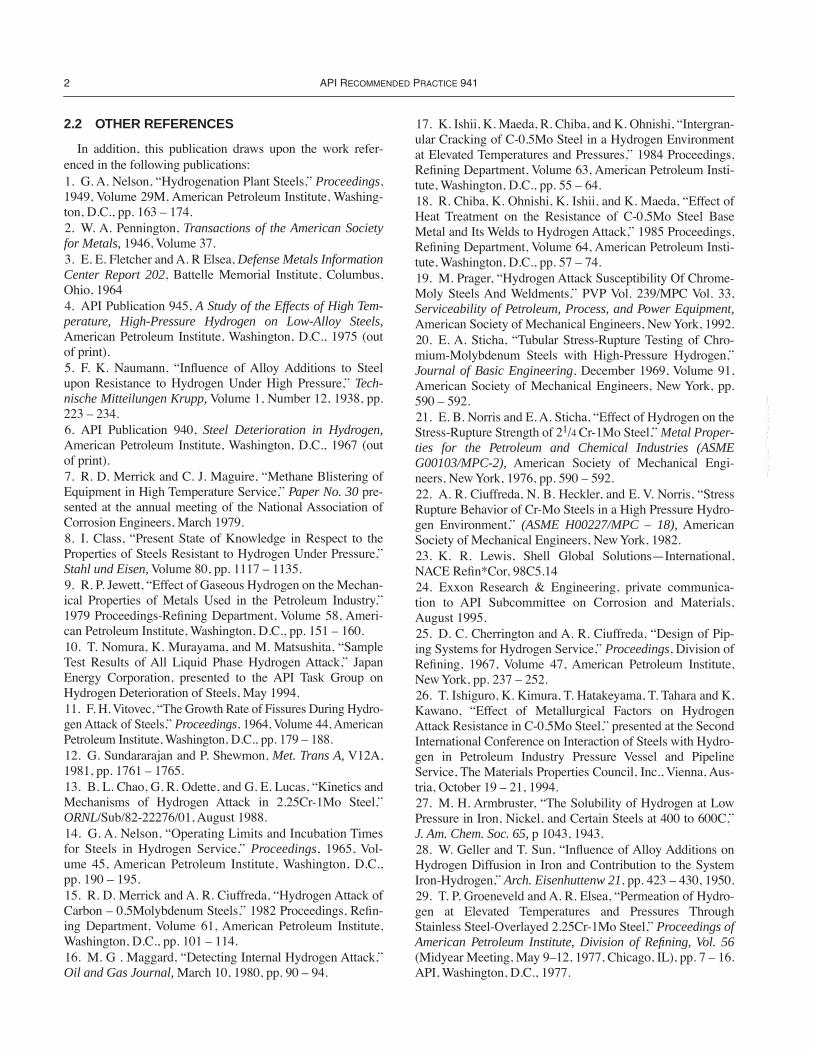
2.2 OTHER REFERENCES
In addition, this publication draws upon the work refer-enced in the following publications:1. G. A. Nelson, ÒHydrogenation Plant Steels,Ó
Proceedings
,1949, Volume 29M, American Petroleum Institute, Washing-ton, D.C., pp. 163 Ð 174.2. W. A. Pennington,
Transactions of the American Societyfor Metals,
1946, Volume 37.3. E. E. Fletcher and A. R Elsea,
Defense Metals InformationCenter Report 202
, Battelle Memorial Institute, Columbus,Ohio, 19644. API Publication
945,
A Study of the Effects of High Tem-perature, High-Pressure Hydrogen on Low-Alloy Steels,
American Petroleum Institute, Washington, D.C., 1975 (outof print).5. F. K. Naumann, ÒInßuence of Alloy Additions to Steelupon Resistance to Hydrogen Under High Pressure,Ó
Tech-nische Mitteilungen Krupp,
Volume 1, Number 12, 1938, pp.223 Ð 234.6. API Publication
940,
Steel Deterioration in Hydrogen,
American Petroleum Institute, Washington, D.C., 1967 (outof print).7. R. D. Merrick and C. J. Maguire, ÒMethane Blistering ofEquipment in High Temperature Service,Ó
Paper No. 30
pre-sented at the annual meeting of the National Association ofCorrosion Engineers, March 1979.8. I. Class, ÒPresent State of Knowledge in Respect to theProperties of Steels Resistant to Hydrogen Under Pressure,Ó
Stahl und Eisen,
Volume 80, pp. 1117 Ð 1135.9. R. P. Jewett, ÒEffect of Gaseous Hydrogen on the Mechan-ical Properties of Metals Used in the Petroleum Industry,Ó1979 Proceedings-ReÞning Department, Volume 58, Ameri-can Petroleum Institute, Washington, D.C., pp. 151 Ð 160.10. T. Nomura, K. Murayama, and M. Matsushita, ÒSampleTest Results of All Liquid Phase Hydrogen Attack,Ó JapanEnergy Corporation, presented to the API Task Group onHydrogen Deterioration of Steels, May 1994.11. F. H. Vitovec, ÒThe Growth Rate of Fissures During Hydro-gen Attack of Steels,Ó
Proceedings
, 1964, Volume 44, AmericanPetroleum Institute, Washington, D.C., pp. 179 Ð 188.12. G. Sundararajan and P. Shewmon,
Met. Trans A,
V12A,1981, pp. 1761 Ð 1765.13. B. L. Chao, G. R. Odette, and G. E. Lucas, ÒKinetics andMechanisms of Hydrogen Attack in 2.25Cr-1Mo Steel,Ó
ORNL
/Sub/82-22276/01, August 1988.14. G. A. Nelson, ÒOperating Limits and Incubation Timesfor Steels in Hydrogen Service,Ó
Proceedings
,
1965, Vol-ume 45, American Petroleum Institute, Washington, D.C.,pp. 190 Ð 195.15. R. D. Merrick and A. R. Ciuffreda, ÒHydrogen Attack ofCarbon Ð 0.5Molybdenum Steels,Ó 1982 Proceedings, ReÞn-ing Department, Volume 61, American Petroleum Institute,Washington, D.C., pp. 101 Ð 114.16. M. G . Maggard, ÒDetecting Internal Hydrogen Attack,Ó
Oil and Gas Journal,
March 10, 1980, pp. 90 Ð 94.
17. K. Ishii, K. Maeda, R. Chiba, and K. Ohnishi, ÒIntergran-ular Cracking of C-0.5Mo Steel in a Hydrogen Environmentat Elevated Temperatures and Pressures,Ó 1984 Proceedings,ReÞning Department, Volume 63, American Petroleum Insti-tute, Washington, D.C., pp. 55 Ð 64.18. R. Chiba, K. Ohnishi, K. Ishii, and K. Maeda, ÒEffect ofHeat Treatment on the Resistance of C-0.5Mo Steel BaseMetal and Its Welds to Hydrogen Attack,Ó 1985 Proceedings,ReÞning Department, Volume 64, American Petroleum Insti-tute, Washington, D.C., pp. 57 Ð 74.19. M. Prager, ÒHydrogen Attack Susceptibility Of Chrome-Moly Steels And Weldments,Ó PVP Vol. 239/MPC Vol. 33,
Serviceability of Petroleum, Process, and Power Equipment,
American Society of Mechanical Engineers, New York, 1992.20. E. A. Sticha, ÒTubular Stress-Rupture Testing of Chro-mium-Molybdenum Steels with High-Pressure Hydrogen,Ó
Journal of Basic Engineering
, December 1969, Volume 91,American Society of Mechanical Engineers, New York, pp.590 Ð 592.21. E. B. Norris and E. A. Sticha, ÒEffect of Hydrogen on theStress-Rupture Strength of 2
1
/
4
Cr-1Mo Steel,Ó
Metal Proper-ties for the Petroleum and Chemical Industries (ASMEG00103/MPC-2),
American Society of Mechanical Engi-neers, New York, 1976, pp. 590 Ð 592.22. A. R. Ciuffreda, N. B. Heckler, and E. V. Norris, ÒStressRupture Behavior of Cr-Mo Steels in a High Pressure Hydro-gen Environment,Ó
(ASME H00227/MPC – 18),
AmericanSociety of Mechanical Engineers, New York, 1982.23. K. R. Lewis, Shell Global SolutionsÑInternational,NACE ReÞn*Cor, 98C5.1424. Exxon Research & Engineering, private communica-tion to API Subcommittee on Corrosion and Materials,August 1995.25. D. C. Cherrington and A. R. Ciuffreda, ÒDesign of Pip-ing Systems for Hydrogen Service,Ó
Proceedings
, Division ofReÞning, 1967, Volume 47, American Petroleum Institute,New York, pp. 237 Ð 252.26. T. Ishiguro, K. Kimura, T. Hatakeyama, T. Tahara and K.Kawano, ÒEffect of Metallurgical Factors on HydrogenAttack Resistance in C-0.5Mo Steel,Ó presented at the SecondInternational Conference on Interaction of Steels with Hydro-gen in Petroleum Industry Pressure Vessel and PipelineService, The Materials Properties Council, Inc., Vienna, Aus-tria, October 19 Ð 21, 1994.27. M. H. Armbruster, ÒThe Solubility of Hydrogen at LowPressure in Iron, Nickel, and Certain Steels at 400 to 600C,Ó
J. Am. Chem. Soc. 65,
p 1043, 1943.28. W. Geller and T. Sun, ÒInßuence of Alloy Additions onHydrogen Diffusion in Iron and Contribution to the SystemIron-Hydrogen,Ó
Arch. Eisenhuttenw 21
, pp. 423 Ð 430, 1950.29. T. P. Groeneveld and A. R. Elsea, ÒPermeation of Hydro-gen at Elevated Temperatures and Pressures ThroughStainless Steel-Overlayed 2.25Cr-1Mo Steel,Ó
Proceedings ofAmerican Petroleum Institute, Division of Refining, Vol. 56
(Midyear Meeting, May 9Ð12, 1977, Chicago, IL), pp. 7 Ð 16.API, Washington, D.C., 1977.
--`,,```,,,,````-`-`,,`,,`,`,,`---
S
TEELS
FOR
H
YDROGEN
S
ERVICE
AT
E
LEVATED
T
EMPERATURES
AND
P
RESSURES
IN
P
ETROLEUM
R
EFINERIES
AND
P
ETROCHEMICAL
P
LANTS
3
30. ÒReport on the Effect of Stainless Steel Weld Overlay orCladding on Hydrogen Attack of Underlying Steel,Ó Materi-als Properties Council, New York, September 1984.31. Archakov and Grebeshkova, Reference 105 in
WeldingResearch Council Bulletin 275
, ÒThe Use of Quenched andTempered 2.25 Cr-1Mo Steel for Thick Wall Reactor Vessels,etc.,Ó W. E. Erwin, J. C. Kerr, February 1982.32. Exxon Report: ÒHydrogen Attack Of GoÞner ReactorInlet Nozzle,Ó 1988.33. G. R. Prescott, ÒHistory and Basis of Prediction ofHydrogen Attack of C-0.5Mo Steel,Ó a state-of-the-art reviewpresented at Second International Conference on Interactionof Steels with Hydrogen in Petroleum Industry Pressure Ves-sel and Pipeline Service, The Materials Properties Council,Inc., Vienna, Austria, October 19 Ð 21,1994.34. W. D. Wang, ÒInspection of ReÞnery Vessels for Hydro-gen Attack Using Ultrasonic Techniques,Ó Review of Progressin
Quantitative Nondestructive Evaluation
, Vol. 12, D. O.Thompson and D. E. Chement, Plenum Press, New York.35. Weicheng D. Wang, ÒUltrasonic Detection of High Tem-perature Hydrogen Attack,Ó United States Patent #5,404754,Issued April 11, 1995.36. W. David Wang, ÒUltrasonic Detection, Characterization,and QuantiÞcation of Localized High Temperature Hydrogenattack in Weld Heat Affected Zone,Ó
In Service Experience inFossil and Nuclear Power Plants,
PVP-Vol. 392, Edited by J.Pan, ASME, New York, 1999, pp. 291 Ð 298.37. Weicheng David Wang, ÒUltrasonic Techniques forInspection of Weld and Heat-Affected Zone for LocalizedHigh Temperature Hydrogen Attack,Ó United States Patent#6,125,704, Issued Oct. 3, 2000.38. R. Bruscato, ÒTemper Embrittlement and Creep Embrit-tlement of 2.25Cr-1Mo Shielded Metal-Arc Weld Deposits,ÓWeld. J. 49, Res. Suppl., pp 148-s Ð 156-s, April 1970.
3 Operating Limits
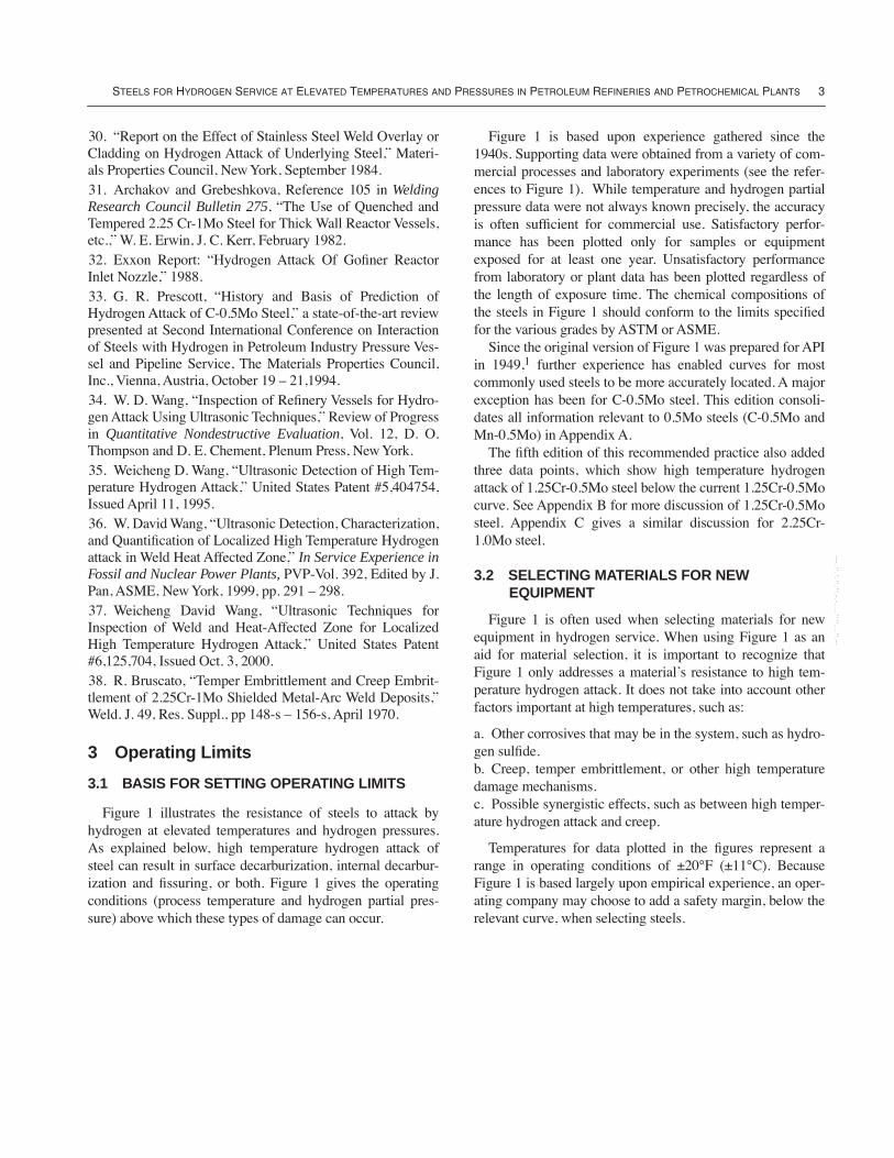
3.1 BASIS FOR SETTING OPERATING LIMITS
Figure 1 illustrates the resistance of steels to attack byhydrogen at elevated temperatures and hydrogen pressures.As explained below, high temperature hydrogen attack ofsteel can result in surface decarburization, internal decarbur-ization and Þssuring, or both. Figure 1 gives the operatingconditions (process temperature and hydrogen partial pres-sure) above which these types of damage can occur.
Figure 1 is based upon experience gathered since the1940s. Supporting data were obtained from a variety of com-mercial processes and laboratory experiments (see the refer-ences to Figure 1). While temperature and hydrogen partialpressure data were not always known precisely, the accuracyis often sufÞcient for commercial use. Satisfactory perfor-mance has been plotted only for samples or equipmentexposed for at least one year. Unsatisfactory performancefrom laboratory or plant data has been plotted regardless ofthe length of exposure time. The chemical compositions ofthe steels in Figure 1 should conform to the limits speciÞedfor the various grades by ASTM or ASME.
Since the original version of Figure 1 was prepared for APIin 1949,
1
further experience has enabled curves for mostcommonly used steels to be more accurately located. A majorexception has been for C-0.5Mo steel. This edition consoli-dates all information relevant to 0.5Mo steels (C-0.5Mo andMn-0.5Mo) in Appendix A.
The Þfth edition of this recommended practice also addedthree data points, which show high temperature hydrogenattack of 1.25Cr-0.5Mo steel below the current 1.25Cr-0.5Mocurve. See Appendix B for more discussion of 1.25Cr-0.5Mosteel. Appendix C gives a similar discussion for 2.25Cr-1.0Mo steel.
3.2 SELECTING MATERIALS FOR NEW EQUIPMENT
Figure 1 is often used when selecting materials for newequipment in hydrogen service. When using Figure 1 as anaid for material selection, it is important to recognize thatFigure 1 only addresses a materialÕs resistance to high tem-perature hydrogen attack. It does not take into account otherfactors important at high temperatures, such as:
a. Other corrosives that may be in the system, such as hydro-gen sulÞde.b. Creep, temper embrittlement, or other high temperaturedamage mechanisms.c. Possible synergistic effects, such as between high temper-ature hydrogen attack and creep.
Temperatures for data plotted in the Þgures represent arange in operating conditions of ±20¡F (±11¡C). BecauseFigure 1 is based largely upon empirical experience, an oper-ating company may choose to add a safety margin, below therelevant curve, when selecting steels.
--`,,```,,,,````-`-`,,`,,`,`,,`---
4 API R
ECOMMENDED
P
RACTICE
941
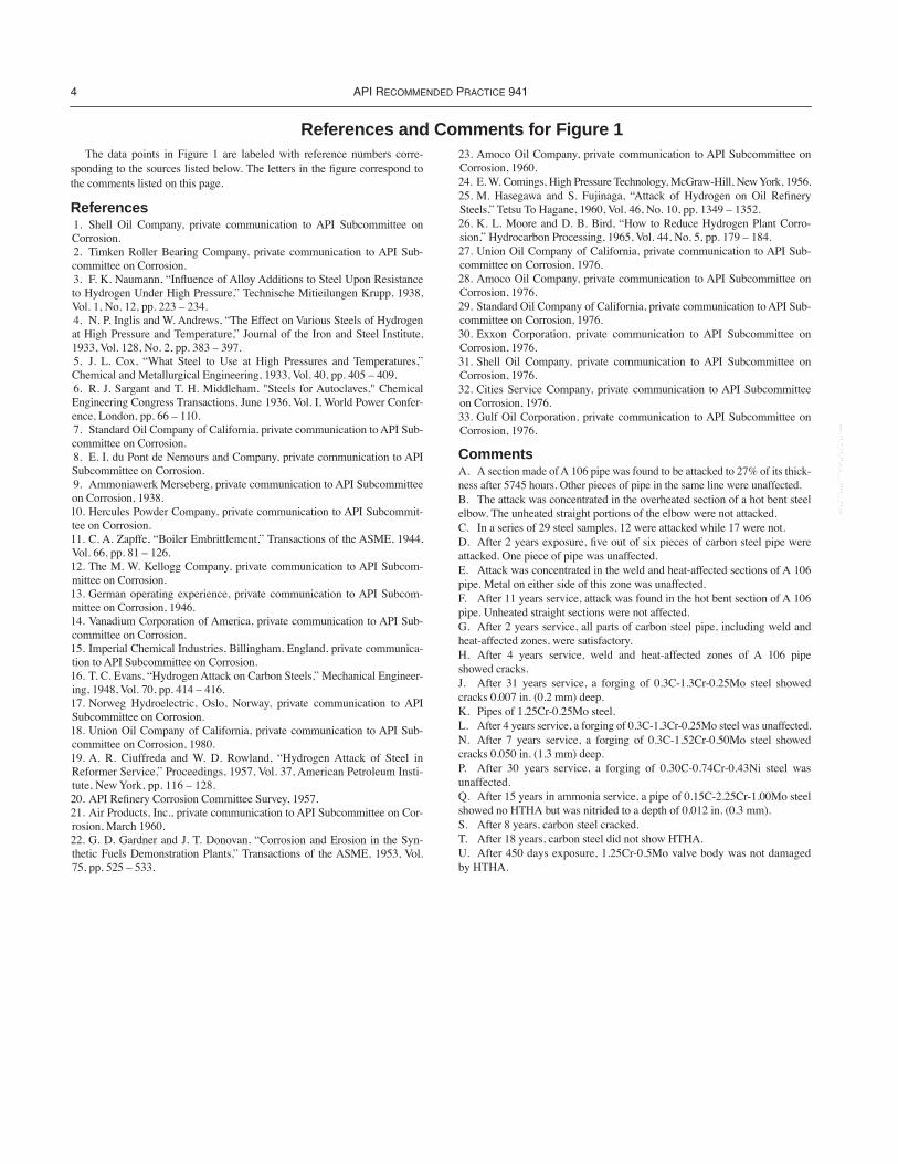
References and Comments for Figure 1
The data points in Figure 1 are labeled with reference numbers corre-sponding to the sources listed below. The letters in the Þgure correspond tothe comments listed on this page.
References
1. Shell Oil Company, private communication to API Subcommittee onCorrosion. 2. Timken Roller Bearing Company, private communication to API Sub-committee on Corrosion. 3. F. K. Naumann, ÒInßuence of Alloy Additions to Steel Upon Resistanceto Hydrogen Under High Pressure,Ó Technische Mitieilungen Krupp, 1938,Vol. 1, No. 12, pp. 223 Ð 234. 4. N. P. Inglis and W. Andrews, ÒThe Effect on Various Steels of Hydrogenat High Pressure and Temperature,Ó Journal of the Iron and Steel Institute,1933, Vol. 128, No. 2, pp. 383 Ð 397. 5. J. L. Cox, ÒWhat Steel to Use at High Pressures and Temperatures,ÓChemical and Metallurgical Engineering, 1933, Vol. 40, pp. 405 Ð 409. 6. R. J. Sargant and T. H. Middleham, "Steels for Autoclaves," ChemicalEngineering Congress Transactions, June 1936, Vol. I, World Power Confer-ence, London, pp. 66 Ð 110. 7. Standard Oil Company of California, private communication to API Sub-committee on Corrosion. 8. E. I. du Pont de Nemours and Company, private communication to APISubcommittee on Corrosion. 9. Ammoniawerk Merseberg, private communication to API Subcommitteeon Corrosion, 1938.10. Hercules Powder Company, private communication to API Subcommit-tee on Corrosion.11. C. A. Zapffe, ÒBoiler Embrittlement,Ó Transactions of the ASME, 1944,Vol. 66, pp. 81 Ð 126.12. The M. W. Kellogg Company, private communication to API Subcom-mittee on Corrosion.13. German operating experience, private communication to API Subcom-mittee on Corrosion, 1946.14. Vanadium Corporation of America, private communication to API Sub-committee on Corrosion.15. Imperial Chemical Industries, Billingham, England, private communica-tion to API Subcommittee on Corrosion. 16. T. C. Evans, ÒHydrogen Attack on Carbon Steels,Ó Mechanical Engineer-ing, 1948, Vol. 70, pp. 414 Ð 416.17. Norweg Hydroelectric, Oslo, Norway, private communication to APISubcommittee on Corrosion.18. Union Oil Company of California, private communication to API Sub-committee on Corrosion, 1980.19. A. R. Ciuffreda and W. D. Rowland, ÒHydrogen Attack of Steel inReformer Service,Ó Proceedings, 1957, Vol. 37, American Petroleum Insti-tute, New York, pp. 116 Ð 128.20. API ReÞnery Corrosion Committee Survey, 1957.21. Air Products, Inc., private communication to API Subcommittee on Cor-rosion, March 1960.22. G. D. Gardner and J. T. Donovan, ÒCorrosion and Erosion in the Syn-thetic Fuels Demonstration Plants,Ó Transactions of the ASME, 1953, Vol.75, pp. 525 Ð 533.
23. Amoco Oil Company, private communication to API Subcommittee onCorrosion, 1960.24. E. W. Comings, High Pressure Technology, McGraw-Hill, New York, 1956.25. M. Hasegawa and S. Fujinaga, ÒAttack of Hydrogen on Oil ReÞnerySteels,Ó Tetsu To Hagane, 1960, Vol. 46, No. 10, pp. 1349 Ð 1352.26. K. L. Moore and D. B. Bird, ÒHow to Reduce Hydrogen Plant Corro-sion,Ó Hydrocarbon Processing, 1965, Vol. 44, No. 5, pp. 179 Ð 184.27. Union Oil Company of California, private communication to API Sub-committee on Corrosion, 1976.28. Amoco Oil Company, private communication to API Subcommittee onCorrosion, 1976.29. Standard Oil Company of California, private communication to API Sub-committee on Corrosion, 1976.30. Exxon Corporation, private communication to API Subcommittee onCorrosion, 1976.31. Shell Oil Company, private communication to API Subcommittee onCorrosion, 1976.32. Cities Service Company, private communication to API Subcommitteeon Corrosion, 1976.33. Gulf Oil Corporation, private communication to API Subcommittee onCorrosion, 1976.
Comments
A. A section made of A 106 pipe was found to be attacked to 27% of its thick-ness after 5745 hours. Other pieces of pipe in the same line were unaffected.B. The attack was concentrated in the overheated section of a hot bent steelelbow. The unheated straight portions of the elbow were not attacked.C. In a series of 29 steel samples, 12 were attacked while 17 were not.D. After 2 years exposure, Þve out of six pieces of carbon steel pipe wereattacked. One piece of pipe was unaffected.E. Attack was concentrated in the weld and heat-affected sections of A 106pipe. Metal on either side of this zone was unaffected.F. After 11 years service, attack was found in the hot bent section of A 106pipe. Unheated straight sections were not affected.G. After 2 years service, all parts of carbon steel pipe, including weld andheat-affected zones, were satisfactory.H. After 4 years service, weld and heat-affected zones of A 106 pipeshowed cracks.J. After 31 years service, a forging of 0.3C-1.3Cr-0.25Mo steel showedcracks 0.007 in. (0.2 mm) deep.K. Pipes of 1.25Cr-0.25Mo steel.L. After 4 years service, a forging of 0.3C-1.3Cr-0.25Mo steel was unaffected.N. After 7 years service, a forging of 0.3C-1.52Cr-0.50Mo steel showedcracks 0.050 in. (1.3 mm) deep.P. After 30 years service, a forging of 0.30C-0.74Cr-0.43Ni steel wasunaffected.Q. After 15 years in ammonia service, a pipe of 0.15C-2.25Cr-1.00Mo steelshowed no HTHA but was nitrided to a depth of 0.012 in. (0.3 mm).S. After 8 years, carbon steel cracked.T. After 18 years, carbon steel did not show HTHA.U. After 450 days exposure, 1.25Cr-0.5Mo valve body was not damagedby HTHA.
--`,,```,,,,````-`-`,,`,,`,`,,`---

3000 5000 7000 9000 11000 13000
200
400
300
500
600
700
800
Tem
pera
ture
, °C
2500200015001000500300
500
400
600
700
800
900
1000
1100
1200
1300
1400
1500
Tem
pera
ture
, °F
Hydrogen Partial Pressure, psia
3.45 6.90 10.34 13.79 17.24 20.7 34.5 48.3 62.1 73.8Hydrogen Partial Pressure, MPa Absolute
0
10
1022
49
1
94
Surface decarburizationInternal decarburization
Satisfactory
Internal decarburizationand fissuring
Surface decarburization
See comments
Legend:
Carbonsteel
1.0Cr0.5Mo
2.25Cr1.00Mo
3.0Cr1.0Mo
6.0Cr0.5Mo
8 (240˚�F)13
8U5 6
3
6
22
17
15
13+0.1%V
24 (28,000)
13+0.5%W0.75%V
3
13
1313 3
14+0.25%V
6.0Cr–0.5Mo steel
3.0Cr–1Mo steel2.25Cr–1Mo–V steel
2.25Cr–1.0Mo steel
1.25Cr–0.5Mo or 1.0Cr–0.5Mo steel
7
1N1Q
1J
1
1
1P
7
1
1L
1N
1 Carbon steel
3
2K
3
1K
1
1
11
20
237
7,3
1
5
237
723
19
12B20A
21G25H
21E
26
23F23
2316C 1D
33S23201119
231
23
23 2318T 1
1
16
3 (1510˚ F)
3
Scale change
1.25Cr–0.5Mo steel
1.0Cr–0.5Mo steel
Note: See App. A and Figure A-1 for 0.5Mo steels
The limits described by these curves are based on service experience originally collected by G.A. Nelson and on additionalinformation gathered by or made available to API. Austenitic stainless steels are generally not decarburized in hydrogen at any temperature or hydrogen pressure.The limits described by these curves are based on experience with cast steel as well as annealed and normalized steels atstress levels defined by Section VIII, Division I, of the ASME code. See 5.3 and 5.4 in text for additional information.Several failures of 1-1/4Cr–1Mo steel have been reported in the satisfactory region. See Appendix B for details.The inclusion of the 2.25Cr–1Mo-V class of steels is based on 10,000+hr laboratory tests where these alloys were at leastequal to the 3Cr–1Mo steel. See Reference 22 listed in Section 2.2.
1.
2.3.
4.5.
Copyright © 1967 by G.A. Nelson. Production rights granted by author to API.This figure was revised by API in 1969, 1983, 1990 and 1996
Notes:
Figure 1—Operating Limits for Steels in Hydrogen Service �to Avoid Decarburization and Fissuring
--`,,```,,,,````-`-`,,`,,`,`,,`---
S
TEELS
FOR
H
YDROGEN
S
ERVICE
AT
E
LEVATED
T
EMPERATURES
AND
P
RESSURES
IN
P
ETROLEUM
R
EFINERIES
AND
P
ETROCHEMICAL
P
LANTS
7
4 Forms of High Temperature Hydrogen Attack
4.1 GENERAL
As noted above, high temperature hydrogen can attacksteels in two ways:
a. Surface decarburization.b. Internal decarburization and Þssuring.
The combination of high temperature and low hydrogenpartial pressure favors surface decarburization without inter-nal decarburization and Þssuring. The combination of lowtemperature, but above 430¡F (221¡C), and high hydrogenpartial pressure favors internal decarburization and Þssuring,which can eventually lead to cracking. Both mechanisms areactive at high temperatures and high hydrogen partial pres-sures. These mechanisms are described more fully below.
The broken-line curves at the top of Figure 1 represent thetendencies for surface decarburization of steels while they arein contact with hydrogen. The solid-line curves represent thetendencies for steels to decarburize internally with resultantÞssuring and cracking created by methane formation.
4.2 SURFACE DECARBURIZATION
Surface decarburization does not produce Þssures. In thisrespect, it is similar to decarburization created by the expo-sure of steel to certain other gases, such as air, oxygen, or car-bon dioxide. The usual effects of surface decarburization area slight, localized reduction in strength and hardness and anincrease in ductility. Because these effects are usually small,there is often much less concern with surface decarburizationthan there is with internal decarburization.
A number of theories have been proposed to explain thissurface decarburization,
2,3,4
but the currently-accepted viewis based on the migration of carbon to the surface where gas-eous compounds of carbon are formed, rendering the steelless rich in carbon. (The gaseous compounds formed are CH
4
or, when oxygen-containing gases are present, CO.) Watervapor hastens the reaction. Carbon in solution diffuses to thesurface so that the rate-controlling mechanism appears to becarbon diffusion. Inasmuch as the carbon in solution is con-tinuously supplied from the carbides, carbide stability isdirectly related to the rate of surface decarburization.
In cases where surface decarburization predominates overinternal attack, the actual values of pressure-temperaturecombinations have not been extensively studied; but the lim-its deÞned by Naumann
5
probably give the most accuratetrends. NaumannÕs work, which is based on 100-hour tests,
indicates decarburization tendencies; however, long-timeexposures have indicated lower operating limits.
4.3 INTERNAL DECARBURIZATION AND FISSURING
The solid-line curves in Figure 1 deÞne the areas abovewhich material damage by internal decarburization and Þssur-ing/cracking have been reported. Below and to the left of thecurve for each alloy, satisfactory performance has been expe-rienced with periods of exposure of up to approximately 50years. At temperatures above and to the right of the solidcurves, internal decarburization and Þssuring/cracking occurs.Internal decarburization and Þssuring are preceded by anincubation period that depends on temperature and hydrogenpartial pressure (see Section 5.2 for further discussion).
Internal decarburization and Þssuring are caused byhydrogen permeating the steel and reacting with carbon toform methane.
5
The methane formed cannot diffuse out ofthe steel and typically accumulates at grain boundaries. Thisresults in high localized stresses which lead to the formationof Þssures, cracks, or blisters in the steel. Fissures in hydro-gen-damaged steel lead to a substantial deterioration ofmechanical properties.
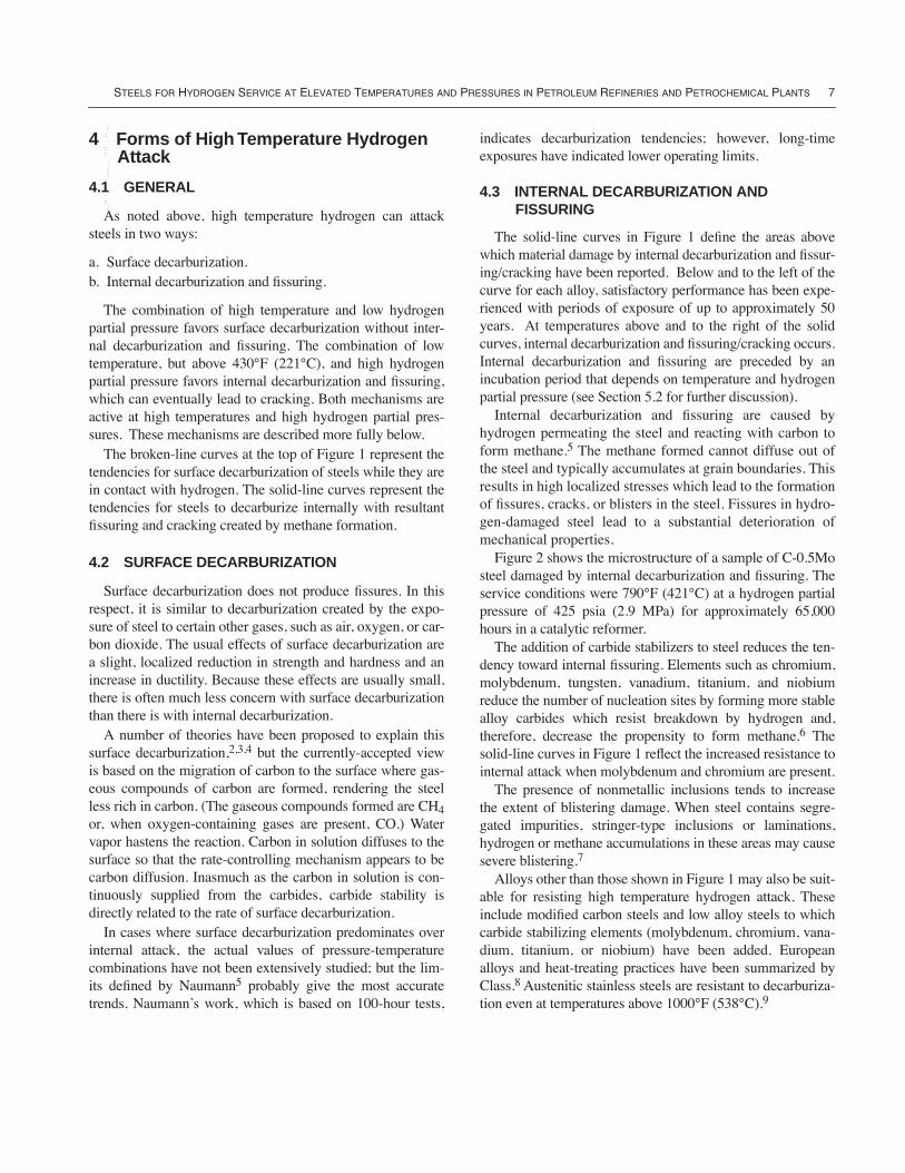
Figure 2 shows the microstructure of a sample of C-0.5Mosteel damaged by internal decarburization and Þssuring. Theservice conditions were 790¡F (421¡C) at a hydrogen partialpressure of 425 psia (2.9 MPa) for approximately 65,000hours in a catalytic reformer.
The addition of carbide stabilizers to steel reduces the ten-dency toward internal Þssuring. Elements such as chromium,molybdenum, tungsten, vanadium, titanium, and niobiumreduce the number of nucleation sites by forming more stablealloy carbides which resist breakdown by hydrogen and,therefore, decrease the propensity to form methane.
6
Thesolid-line curves in Figure 1 reßect the increased resistance tointernal attack when molybdenum and chromium are present.
The presence of nonmetallic inclusions tends to increasethe extent of blistering damage. When steel contains segre-gated impurities, stringer-type inclusions or laminations,hydrogen or methane accumulations in these areas may causesevere blistering.
7
Alloys other than those shown in Figure 1 may also be suit-able for resisting high temperature hydrogen attack. Theseinclude modiÞed carbon steels and low alloy steels to whichcarbide stabilizing elements (molybdenum, chromium, vana-dium, titanium, or niobium) have been added. Europeanalloys and heat-treating practices have been summarized byClass.
8
Austenitic stainless steels are resistant to decarburiza-tion even at temperatures above 1000¡F (538¡C).
9
--`,,```,,,,````-`-`,,`,,`,`,,`---
8 API R
ECOMMENDED
P
RACTICE
941
5 Factors Influencing HTHA
5.1 HIGH TEMPERATURE HYDROGEN ATTACK IN A LIQUID HYDROCARBON PHASE
High temperature hydrogen attack can occur in a liquidhydrocarbon phase if it can occur in the gas phase in equilib-rium with the liquid phase. For materials selection purposes(using Figure 1), hydrogen dissolved in liquid hydrocarbonshould be assumed to exert a vapor pressure equal to thehydrogen partial pressure of the gas with which the liquid isin equilibrium. Recent plant experience and testing of Þeld-exposed specimens have shown that high temperature hydro-gen attack can occur under such conditions.
10
High temperature hydrogen attack has been found in car-bon steel, liquid-Þlled piping downstream of a heavy oil des-ulfurization unit separator that was operating at hydrogenpartial pressure and temperature conditions above the Figure1 carbon steel curve. Testing of Þeld-exposed test specimensshowed high temperature hydrogen attack of both chrome-plated and bare carbon steel samples which were totallyimmersed in liquid.
10
5.2 INCUBATION TIME
Damage to steels by high pressure, high temperaturehydrogen is preceded by a period of time when no noticeablechange in properties is detectable by current mechanical test-ing methods. After this period of time has elapsed, materialdamage is evident with resultant decreases in strength, ductil-ity, and toughness. The length of time before high tempera-ture hydrogen attack can be detected by usual mechanicaltesting methods is termed the incubation period. This periodvaries with the type of steel and severity of exposure; it maylast only a few hours under extreme conditions and becomeprogressively longer at lower temperatures and hydrogen par-tial pressures. With some steels under mild conditions, nodamage can be detected by mechanical testing methods evenafter many years of exposure. During this initial stage ofattack, in some cases, laboratory examination (high magniÞ-cation metallography, utilizing optical microscopy and scan-ning electron microscopy) of samples removed from theequipment have revealed voids at grain boundaries.
The length of the incubation period is important because itdetermines the useful life of a steel at conditions under whichhigh temperature hydrogen attack occurs. Useful theoreticalmodels of the high temperature hydrogen attack mechanismand incubation period have been proposed.
11, 12, 13
High tem-
Notes:
1. Service conditions were 65,000 hours in a catalytic reformer at a temperature of 790¡F (421¡C) and a hydrogen partial pressure of 425 psia (2.9 MPa). From Reference 11.
2. MagniÞcation: 520
x
; nital etched.
Figure 2ÑC-0.5Mo Steel (ASTM A 204-A) Showing Internal Decarburization and Fissuring in High Temperature Hydrogen Service
Fissure
Unaltered pearlite
Decarburized zone
Ferrite
--`,,```,,,,````-`-`,,`,,`,`,,`---

S
TEELS
FOR
H
YDROGEN
S
ERVICE
AT
E
LEVATED
T
EMPERATURES
AND
P
RESSURES
IN
P
ETROLEUM
R
EFINERIES
AND
PETROCHEMICAL PLANTS 9
perature hydrogen attack can be viewed as occurring in threestages:
a. The incubation period during which mechanical propertieschange very slowly and the changes are not detectable.
b. The stage of rapid mechanical property deterioration asso-ciated with rapid Þssure growth.
c. The Þnal stage where carbon in solid solution is exhaustedand mechanical properties reach their Þnal value.
During the incubation period, methane pressure builds upin submicroscopic voids. These voids grow slowly due bothto internal methane pressure and applied stress. When thevoids reach a critical size, and begin connecting to form Þs-sures, the effects on mechanical properties become evident.The incubation period depends on many variables, includingthe type of steel, degree of cold working, amount of impurityelements, applied stress, hydrogen pressure, and temperature.
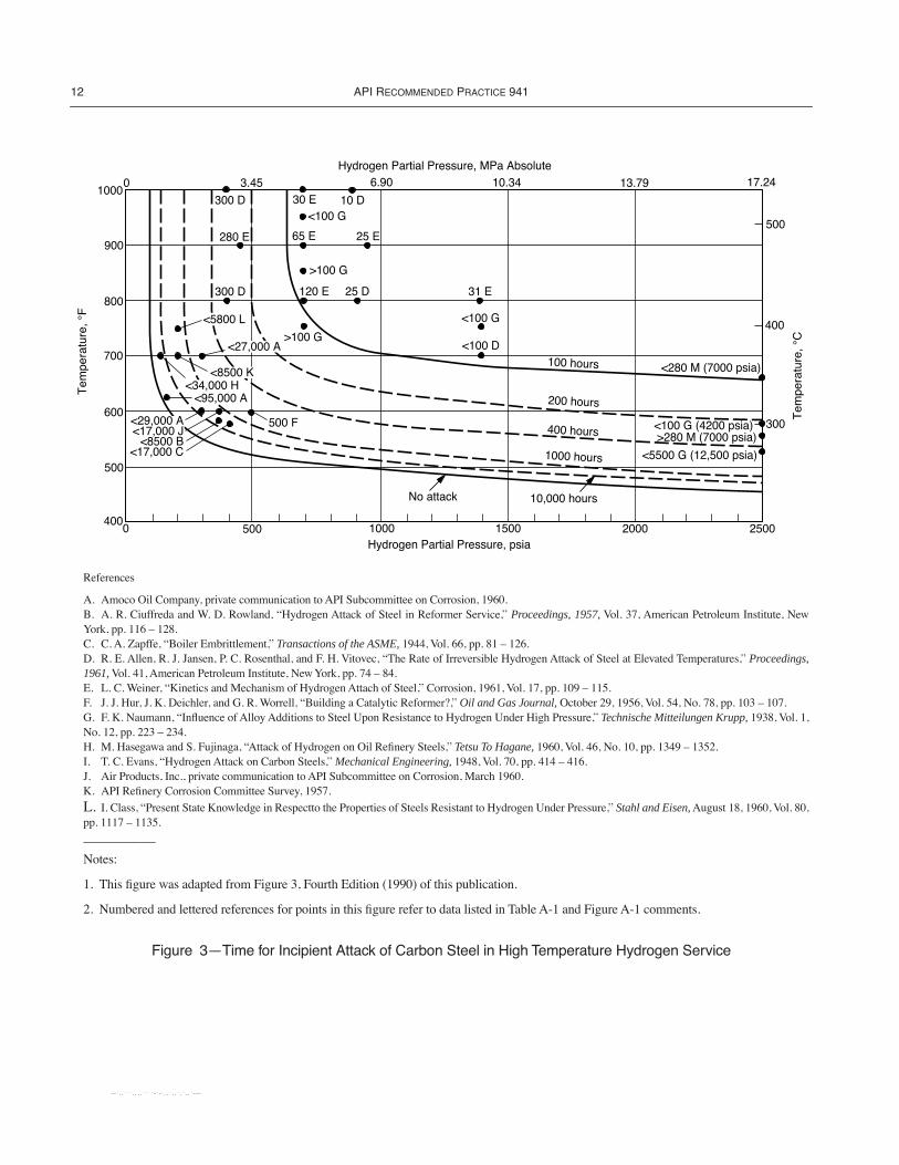
Incubation curves for carbon steel are given in Figure 3.14
These can be used as a guide in determining approximate safeoperating times for steels that operate above their long-termexperience curves. Appendix A includes similar curves thatmay be useful for some heats of C-0.5Mo steel, with the pre-caution that resistance of C-0.5Mo steel to high temperaturehydrogen attack is particularly sensitive to heat treatment,chemical composition, and the heating/cooling history of thesteel during forming.15, 16, 17, 18
5.3 EFFECT OF PRIMARY STRESSES
Many users have reported satisfactory performance ofannealed or normalized and tempered steels produced before1969, as shown in Figure 1. These steels have been used forpressure-retaining equipment at design stress levels allowedby the 1969 or earlier editions of commonly-accepted codes(such codes include the ASME Code, Section VIII, Division1; the standards of the American National Standards Institute;and, for the lower-strength materials, those of DeutscheIndustrie-Normen). However, pressure vessels in hydrogenservice have also been constructed using the higher allowablestresses permitted in Section VIII, Division 2, or modiÞca-tions of Section III of the ASME Code. Quenched and tem-pered or normalized and tempered steels have normally beenutilized for these vessels due to their improved mechanicalproperties (strength and impact toughness).
No incidents of decarburization or Þssuring of pressurevessels built to the speciÞcations of Section VIII, Division 2,of the ASME Code have been reported. None of the failuredata in Figure 1 represent materials used at the higher allow-able stresses.
Published laboratory creep studies19 have shown that therupture strength and rupture ductility of 2.25Cr-1Mo steel arediminished when tested in hydrogen as compared to their val-ues in air. These tests were a continuation of previously-
reported tests20, 21, 22 that showed somewhat conßictingresults in shorter term tests.
These tests were conducted at applied stress levels similar tothose that might be experienced by ASME Section VIII, Divi-sion 2 vessels. Test exposure times exceeded 50,000 hoursdepending on applied stress and temperature. The test speci-mens were from weldments of thick section plates and repre-sented base metal, weld metal, and heat-affected zone.Detrimental effects of hydrogen were found down to the Figure1 limit of 850¡F (454¡C) at 2000 psia (14 MPa) and 3000 psia(21 MPa) hydrogen partial pressure. In rare cases unusuallyhigh localized stresses have caused high temperature hydro-gen attack under temperature and hydrogen partial pressureconditions that are not expected to cause damage according tothe Figure 1 curves.23 However, there is no report of HTHAbelow the Figure 1 limits when stresses are within ASMECode limits.
5.4 EFFECT OF SECONDARY STRESSES
High temperature hydrogen attack can be accelerated bysecondary stresses, such as thermal stresses or those inducedby cold work. High thermal stresses were considered to play asigniÞcant role in the high temperature hydrogen attack ofsome 2.25Cr-1Mo steel piping.24 Other 2.25Cr-1Mo steelpiping in the same system, subjected to more severe hydrogenpartial pressures and temperatures, was not attacked.
The effect of cold work was demonstrated by Vitovec inwork sponsored by API and summarized in API Publication940.6 Vitovec compared speciÞc gravities of SAE 1020 steelwith varying degrees of cold work tested in 900 psi (6.2 MPa)hydrogen at 700¡F (371¡C), 800¡F (427¡C), and 1000¡F(538¡C). The decrease in speciÞc gravity over time indicatesthe rate at which internal Þssures produced by high tempera-ture hydrogen attack are developed.
Annealed samples (0% strain) had an incubation period fol-lowed by a decrease in speciÞc gravity. Steels with 5% strainhad shorter incubation periods, and speciÞc gravity decreasedat a more rapid rate. Steels with 39% strain showed no incuba-tion period at any test temperature, indicating that Þssuringand cracking started immediately upon exposure to hydrogen.
These tests are considered signiÞcant in explaining thecracks sometimes found in highly stressed areas of an other-wise apparently resistant material. In addition, Cherringtonand Ciuffreda25 have emphasized the need for removingnotches (stress concentrators) in hydrogen service equipment.
5.5 EFFECT OF HEAT TREATMENT
Both industry experience and research work indicate thatpostweld heat treatment (PWHT) of chromium-molybdenumsteels in hydrogen service improves resistance to high tem-perature hydrogen attack. The PWHT stabilizes alloy car-bides. This reduces the amount of carbon available tocombine with hydrogen, thus improving high temperature
--`,,```,,,,````-`-`,,`,,`,`,,`---
10 API RECOMMENDED PRACTICE 941
hydrogen attack resistance. Also, PWHT reduces residualstresses and is therefore beneÞcial for all steels.
Research 4, 13, 17, 18, 26 has shown that certain metal car-bides may be more resistant to decomposition in high temper-ature hydrogen environments. Creep tests in hydrogendemonstrated the beneÞcial effect of increased PWHT on thehigh temperature hydrogen attack resistance of 2.25Cr-1Mosteel.19 In these tests, 2.25Cr-1Mo steels postweld heattreated for 16 hours at 1275¡F (691¡C) showed more resis-tance to high temperature hydrogen attack than the samesteels postweld heat treated for 24 hours at 1165¡F (630¡C).Both high PWHT temperatures and longer times are beneÞ-cial. Similarly, high temperature hydrogen attack resistanceof 1Cr-0.5Mo and 1.25Cr-0.5Mo steels is improved by rais-ing the minimum PWHT temperature to 1250¡F (677¡C)from the 1100¡F (593¡C) minimum required by Section VIIIof the ASME Code.
The user must balance the advantages of high PWHT tem-peratures with other factors, such as the effect upon strengthand notch toughness. Note higher PWHT temperatures canaffect the ability to meet ASME Code Class 2 strengthrequirements.
5.6 EFFECT OF STAINLESS STEEL CLADDING OR WELD OVERLAY
The solubility of hydrogen in austenitic stainless steel isabout an order of magnitude greater than for ferritic steels.27
The diffusion coefÞcient of hydrogen through austeniticstainless steel is roughly two orders of magnitude lower thanfor ferritic steels.28, 29 A sound, metallurgically bonded auste-nitic stainless steel cladding or weld overlay can reduce theeffective hydrogen partial pressure acting on the base metal.Ferritic or martensitic claddings or weld overlays have littleor no beneÞt in reducing the hydrogen partial pressure actingon the base metal.
The amount of hydrogen partial pressure reductiondepends on the materials and the relative thickness of thecladding/weld overlay and the base metal. The thicker theaustenitic stainless steel barrier is relative to the base metal,the better.30 Archakov and Grebeshkova31 mathematicallyconsidered how stainless steel corrosion barrier layersincrease resistance of carbon and low alloy steels to high tem-perature hydrogen attack.
There have been a few instances of high temperaturehydrogen attack of base metal that was clad or overlayed withaustenitic stainless steel. All of the reported instancesinvolved C-0.5Mo steel base metal. In one case,32 high tem-perature hydrogen attack occurred in a reactor vessel at a noz-zle location where the C-0.5Mo base metal was very thickrelative to the cladding/overlay. Another incident of high tem-perature hydrogen attack of C-0.5Mo steel occurred underintergranularly cracked Type 304 austenitic stainless steel
cladding (see data point 51U in Appendix A). The other casesinvolved ferritic or martensitic stainless steel cladding.
It is not advisable to take a credit for the presence of anaustenitic stainless steel cladding/weld overlay when select-ing the base metal for a new vessel or when operating anexisting vessel long term in high temperature hydrogen ser-vice. Some operators have successfully taken some credit forthe presence of an austenitic stainless steel cladding/weldoverlay for short-term operation when conditions only mar-ginally exceeded the Figure 1 curve for the base metal. Satis-factory performance in such cases requires assurance that theeffective hydrogen partial pressure acting on the base metalbe accurately determined and that the integrity of the clad-ding/weld overlay be maintained. Such assurance may be dif-Þcult to achieve, especially where complex geometries areinvolved. Many operators take the presence of an austeniticstainless steel cladding/weld overlay into account whenestablishing inspection priorities for HTHA, especially for C-0.5Mo steel equipment.
6 Inspection for HTHA
The selection of optimum inspection methods and frequen-cies for high temperature hydrogen attack in speciÞc equip-ment or applications is the responsibility of the user. Theinformation below and in Tables D-1 and D-2 are intended toassist the user in making such decisions.
Experience with steels operated below their respective Fig-ure 1 Nelson curves has been good. Consequently, most usersdo not inspect equipment for high temperature hydrogenattack damage unless it has been operated near or above itscurve. A high temperature attack inspection program shouldalso consider equipment that operates infrequently above itscurve (e.g., operations such as Òhot hydrogen strippingÓ inhydroprocessing reactors and associated piping and equip-ment). Only a small number of documented instances of hightemperature hydrogen attack occurring at conditions belowthe curves have been reported to the API (see Appendixes A,B, and C). Most of these have involved C-0.5Mo steel.33
Periodic inspection of C-0.5Mo steel equipment and pipingshould be considered if operated above the carbon steelcurve, based on factors such as relative position of the oper-ating parameters versus the carbon steel curve, consequenceof failure, presence of cladding, prior heat treatment, etc.Because HTHA is time dependent, existing C-0.5Mo steelequipment and piping may continue to deteriorate withtime, if susceptible. As this equipment and piping age theowner should consider increasing the inspection frequency.See Appendix A.
High temperature hydrogen attack damage may occur inwelds, weld HAZs, or base metal. Even within these speciÞcareas, the degree of damage may vary widely. Consequently,if damage is suspected, then a thorough inspection means thatrepresentative samples of these areas be examined.
--`,,```,,,,````-`-`,,`,,`,`,,`---
STEELS FOR HYDROGEN SERVICE AT ELEVATED TEMPERATURES AND PRESSURES IN PETROLEUM REFINERIES AND PETROCHEMICAL PLANTS 11
Tables D-1 and D-2 provide a summary of available meth-ods of inspection for HTHA damage, including a discussionof the advantages and limitations of each. Two or moreinspection methods are often used in combination to over-come the limitations of any single method.34, 35
High temperature hydrogen attack is a difÞcult inspectionchallenge. The early stages of attack with Þssures, or evensmall cracks, can be difÞcult to detect. The advanced stage ofattack with signiÞcant cracking is much easier to detect, butat that point there is already a higher likelihood of equipmentfailure. In addition to general attack of the base metal, hightemperature hydrogen attack has been known to occur as avery narrow band of intense attack and cracking, runningalongside and parallel to welds. This highly localized form ofattack requires special nondestructive testing (NDT) tech-niques for detection, such as high frequency shear wave andangle-beam spectrum analysis.36, 37
For base metal examination, ultrasonic testing (UT) meth-ods have the best chance of detecting high temperature hydro-gen attack damage in the Þssuring stage. Most effective is theuse of a frequency dependent backscatter method in combina-tion with the velocity ratio and spectral analysis techniques.Backscatter can be used as a Þrst step of inspection and canbe used to quantify the depth of damage. Velocity ratio andspectral analysis are useful for conÞrmation of backscatter
indications. Other methods are capable of detecting high tem-perature hydrogen attack only after discrete cracks haveformed and there is signiÞcant degradation of mechanicalproperties.
For weldment examination, only two UT methods ofexamination are considered effective. High frequency shearwave and angle-beam spectrum analysis techniques should beused to detect high temperature hydrogen attack damage inthe Þssuring stage. Conventional shear wave UT and time ofßight diffraction (TOFD) techniques can be used to detectHTHA in the advanced stages, when there is signiÞcantcracking.
When the internal surface is accessible, wet ßuorescentmagnetic particle testing (WFMT) can be used to Þnd HTHAdamage in the form of surface breaking cracks. In situ metal-lography can be effective in detecting the early stages of hightemperature hydrogen attack (decarburization and Þssuring)at the surface of the steel as well as differentiating betweenHTHA and other forms of cracking. Skill is required for thesurface polishing, etching, replication, and microstructuralinterpretation. Because in situ metallography only examines asmall speciÞc area, other methods should be used to comple-ment it. It requires access to the surface of interest, and mayrequire removal of a small amount of surface material fromthe process side for best results (see Table D-2).
--`,,```,,,,````-`-`,,`,,`,`,,`---
12 API RECOMMENDED PRACTICE 941
Figure 3ÑTime for Incipient Attack of Carbon Steel in High Temperature Hydrogen Service
500
600
700
800
300
400
500
3.45 13.7910.34 17.246.90Hydrogen Partial Pressure, MPa Absolute
1000
25002000150010000Hydrogen Partial Pressure, psia
0
900
500
<27,000 A
300 D
<8500 K
<95,000 A<34,000 H
<5800 L
<29,000 A<17,000 J
<8500 B<17,000 C
>100 G<100 D
No attack
100 hours
400 hours
1000 hours
200 hours
<100 G
31 E
10,000 hours
500 F
10 D
120 E 25 D
>100 G
65 E
<100 G30 E
25 E280 E
300 D
<280 M (7000 psia)
<100 G (4200 psia)
<5500 G (12,500 psia)
>280 M (7000 psia)
400
References
A. Amoco Oil Company, private communication to API Subcommittee on Corrosion, 1960. B. A. R. Ciuffreda and W. D. Rowland, ÒHydrogen Attack of Steel in Reformer Service,Ó Proceedings, 1957, Vol. 37, American Petroleum Institute, NewYork, pp. 116 Ð 128.C. C. A. Zapffe, ÒBoiler Embrittlement,Ó Transactions of the ASME, 1944, Vol. 66, pp. 81 Ð 126.D. R. E. Allen, R. J. Jansen, P. C. Rosenthal, and F. H. Vitovec, ÒThe Rate of Irreversible Hydrogen Attack of Steel at Elevated Temperatures,Ó Proceedings,1961, Vol. 41, American Petroleum Institute, New York, pp. 74 Ð 84.E. L. C. Weiner, ÒKinetics and Mechanism of Hydrogen Attach of Steel,Ó Corrosion, 1961, Vol. 17, pp. 109 Ð 115.F. J. J. Hur, J. K. Deichler, and G. R. Worrell, ÒBuilding a Catalytic Reformer?,Ó Oil and Gas Journal, October 29, 1956, Vol. 54, No. 78, pp. 103 Ð 107.G. F. K. Naumann, ÒInßuence of Alloy Additions to Steel Upon Resistance to Hydrogen Under High Pressure,Ó Technische Mitteilungen Krupp, 1938, Vol. 1,No. 12, pp. 223 Ð 234.H. M. Hasegawa and S. Fujinaga, ÒAttack of Hydrogen on Oil ReÞnery Steels,Ó Tetsu To Hagane, 1960, Vol. 46, No. 10, pp. 1349 Ð 1352.I. T. C. Evans, ÒHydrogen Attack on Carbon Steels,Ó Mechanical Engineering, 1948, Vol. 70, pp. 414 Ð 416.J. Air Products, Inc., private communication to API Subcommittee on Corrosion, March 1960.K. API ReÞnery Corrosion Committee Survey, 1957.
L. I. Class, ÒPresent State Knowledge in Respectto the Properties of Steels Resistant to Hydrogen Under Pressure,Ó Stahl and Eisen, August 18, 1960, Vol. 80,pp. 1117 Ð 1135.__________
Notes:
1. This Þgure was adapted from Figure 3, Fourth Edition (1990) of this publication.
2. Numbered and lettered references for points in this Þgure refer to data listed in Table A-1 and Figure A-1 comments.
--`,,```,,,,````-`-`,,`,,`,`,,`---
13
APPENDIX A—HIGH TEMPERATURE HYDROGEN ATTACK OF 0.5Mo STEELS
A.1 GeneralThe purpose of this appendix is to provide a brief summary
of the information and experience regarding the use of 0.5Mo(C-0.5Mo, Mn-0.5Mo) steels in elevated temperature andpressure hydrogen service.
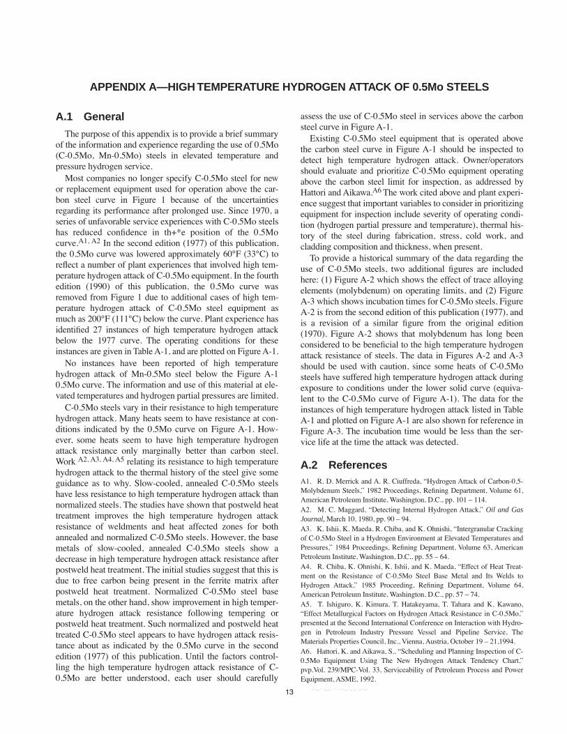
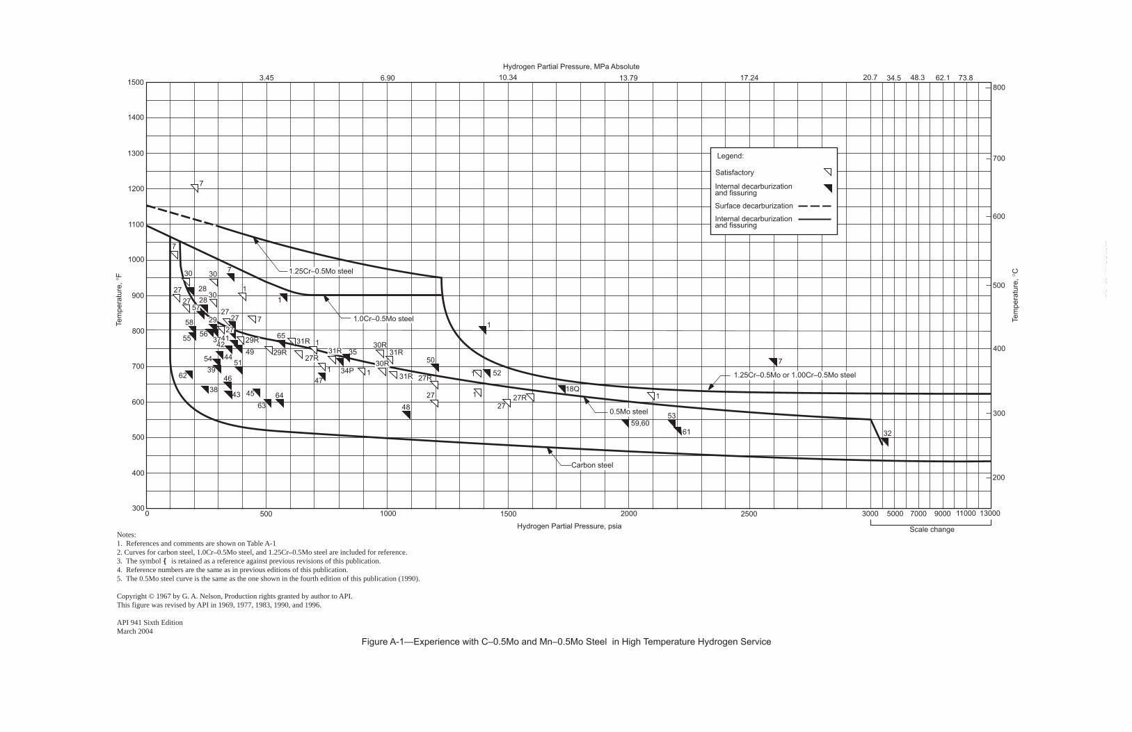
Most companies no longer specify C-0.5Mo steel for newor replacement equipment used for operation above the car-bon steel curve in Figure 1 because of the uncertaintiesregarding its performance after prolonged use. Since 1970, aseries of unfavorable service experiences with C-0.5Mo steelshas reduced conÞdence in th+*e position of the 0.5Mocurve.A1, A2 In the second edition (1977) of this publication,the 0.5Mo curve was lowered approximately 60¡F (33¡C) toreßect a number of plant experiences that involved high tem-perature hydrogen attack of C-0.5Mo equipment. In the fourthedition (1990) of this publication, the 0.5Mo curve wasremoved from Figure 1 due to additional cases of high tem-perature hydrogen attack of C-0.5Mo steel equipment asmuch as 200¡F (111¡C) below the curve. Plant experience hasidentiÞed 27 instances of high temperature hydrogen attackbelow the 1977 curve. The operating conditions for theseinstances are given in Table A-1, and are plotted on Figure A-1.
No instances have been reported of high temperaturehydrogen attack of Mn-0.5Mo steel below the Figure A-10.5Mo curve. The information and use of this material at ele-vated temperatures and hydrogen partial pressures are limited.
C-0.5Mo steels vary in their resistance to high temperaturehydrogen attack. Many heats seem to have resistance at con-ditions indicated by the 0.5Mo curve on Figure A-1. How-ever, some heats seem to have high temperature hydrogenattack resistance only marginally better than carbon steel.Work A2, A3, A4, A5 relating its resistance to high temperaturehydrogen attack to the thermal history of the steel give someguidance as to why. Slow-cooled, annealed C-0.5Mo steelshave less resistance to high temperature hydrogen attack thannormalized steels. The studies have shown that postweld heattreatment improves the high temperature hydrogen attackresistance of weldments and heat affected zones for bothannealed and normalized C-0.5Mo steels. However, the basemetals of slow-cooled, annealed C-0.5Mo steels show adecrease in high temperature hydrogen attack resistance afterpostweld heat treatment. The initial studies suggest that this isdue to free carbon being present in the ferrite matrix afterpostweld heat treatment. Normalized C-0.5Mo steel basemetals, on the other hand, show improvement in high temper-ature hydrogen attack resistance following tempering orpostweld heat treatment. Such normalized and postweld heattreated C-0.5Mo steel appears to have hydrogen attack resis-tance about as indicated by the 0.5Mo curve in the secondedition (1977) of this publication. Until the factors control-ling the high temperature hydrogen attack resistance of C-0.5Mo are better understood, each user should carefully
assess the use of C-0.5Mo steel in services above the carbonsteel curve in Figure A-1.
Existing C-0.5Mo steel equipment that is operated abovethe carbon steel curve in Figure A-1 should be inspected todetect high temperature hydrogen attack. Owner/operatorsshould evaluate and prioritize C-0.5Mo equipment operatingabove the carbon steel limit for inspection, as addressed byHattori and Aikawa.A6 The work cited above and plant experi-ence suggest that important variables to consider in prioritizingequipment for inspection include severity of operating condi-tion (hydrogen partial pressure and temperature), thermal his-tory of the steel during fabrication, stress, cold work, andcladding composition and thickness, when present.
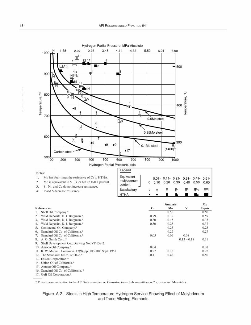
To provide a historical summary of the data regarding theuse of C-0.5Mo steels, two additional Þgures are includedhere: (1) Figure A-2 which shows the effect of trace alloyingelements (molybdenum) on operating limits, and (2) FigureA-3 which shows incubation times for C-0.5Mo steels. FigureA-2 is from the second edition of this publication (1977), andis a revision of a similar Þgure from the original edition(1970). Figure A-2 shows that molybdenum has long beenconsidered to be beneÞcial to the high temperature hydrogenattack resistance of steels. The data in Figures A-2 and A-3should be used with caution, since some heats of C-0.5Mosteels have suffered high temperature hydrogen attack duringexposure to conditions under the lower solid curve (equiva-lent to the C-0.5Mo curve of Figure A-1). The data for theinstances of high temperature hydrogen attack listed in TableA-1 and plotted on Figure A-1 are also shown for reference inFigure A-3. The incubation time would be less than the ser-vice life at the time the attack was detected.
A.2 ReferencesA1. R. D. Merrick and A. R. Ciuffreda, ÒHydrogen Attack of Carbon-0.5-Molybdenum Steels,Ó 1982 Proceedings, ReÞning Department, Volume 61,American Petroleum Institute, Washington, D.C., pp. 101 Ð 114.A2. M. C. Maggard, ÒDetecting Internal Hydrogen Attack,Ó Oil and GasJournal, March 10, 1980, pp. 90 Ð 94.A3. K. Ishii, K. Maeda, R. Chiba, and K. Ohnishi, ÒIntergranular Crackingof C-0.5Mo Steel in a Hydrogen Environment at Elevated Temperatures andPressures,Ó 1984 Proceedings, ReÞning Department, Volume 63, AmericanPetroleum Institute, Washington, D.C., pp. 55 Ð 64.A4. R. Chiba, K. Ohnishi, K. Ishii, and K. Maeda, ÒEffect of Heat Treat-ment on the Resistance of C-0.5Mo Steel Base Metal and Its Welds toHydrogen Attack,Ó 1985 Proceeding, ReÞning Department, Volume 64,American Petroleum Institute, Washington, D.C., pp. 57 Ð 74.A5. T. Ishiguro, K. Kimura, T. Hatakeyama, T. Tahara and K. Kawano,ÒEffect Metallurgical Factors on Hydrogen Attack Resistance in C-0.5Mo,Ópresented at the Second International Conference on Interaction with Hydro-gen in Petroleum Industry Pressure Vessel and Pipeline Service, TheMaterials Properties Council, Inc., Vienna, Austria, October 19 Ð 21,1994.A6. Hattori, K. and Aikawa, S., ÒScheduling and Planning Inspection of C-0.5Mo Equipment Using The New Hydrogen Attack Tendency Chart,Ópvp.Vol. 239/MPC-Vol. 33, Serviceability of Petroleum Process and PowerEquipment, ASME, 1992.
--`,,```,,,,````-`-`,,`,,`,`,,`---

14 API RECOMMENDED PRACTICE 941
References and Comments for Figure A-1The data in Figure A-1 are labeled with reference numbers corresponding
to the sources listed below. The letters in the Þgure correspond to the com-ments listed on this page.
References1. Shell Oil Company, private communication to API Subcommittee onCorrosion.7. Standard Oil Company of California, private communication to API Sub-committee on Corrosion.18. Union Oil Company of California, private communication to API Sub-committee on Corrosion, 1980.27. Union Oil Company of California, private communication to API Sub-committee on Corrosion, 1976.28. Amoco Oil Company, private communication to API Subcommittee onCorrosion, 1976.29. Standard Oil Company of California, private communication to API Sub-committee on Corrosion, 1976.30. Exxon Corporation, private communication to API Subcommittee onCorrosion, 1976.31. Shell Oil Company, private communication to API Subcommittee onCorrosion, 1976.32. Cities Service Company, private communication to API Subcommitteeon Corrosion, 1976.34. Koch ReÞning Company, private communication to API Subcommitteeon Corrosion, 1980.36. ATexaco Incorporated, private communication to API Subcommittee onCorrosion, 1980.37. BExxon Corporation, private communication to API Subcommittee onCorrosion, 1979.38. CExxon Corporation.39. DExxon Corporation.41. FCaltex Petroleum Corporation, private communication to API Subcom-mittee on Corrosion, 1980.42. GGetty Oil Company.43. MGetty Oil Company.44. ICaltex Petroleum Corporation, private communication to API Subcom-mittee on Corrosion and Materials Engineering, 1984.45. JJGC Corporation/Japan Steel Works, API Midyear ReÞning Meeting,1984 (10).46. K,EJGC Corporation/Japan Steel Works, Exxon Corporation.47. LJGC Corporation/Japan Steel Works, API Midyear ReÞning Meeting, 1985.48. MAir Products & Chemicals, Inc., private communication to API Sub-committee on Corrosion and Materials Engineering, 1985.49. STexaco USA, API Fall ReÞning Meeting, 1985.50. TMobil R&D Corporation, private communication to API Subcommitteeon Corrosion and Materials Engineering, 1986.51. UShell Oil Company, private communication to API Subcommittee onMaterials Engineering and Inspection, 1987.52. VTexaco, Inc., private communication to API Subcommittee on Corro-sion, 1981.53. Kemira, B. V., private communication to API subcommittee on MaterialsEngineerings & Inspection, 1986.54. AAChevron Research and Technology Company, private communicationto API Subcommittee on Corrosion and Materials, June 1992.55. BBChevron Research and Technology Company, private communicationto API Subcommittee on Corrosion and Materials, June 1992.56. CCChevron Research and Technology Company, private communicationto API Subcommittee on Corrosion and Materials, June 1992.57. DDChevron Research and Technology Company, private communicationto API Subcommittee on Corrosion and Materials, June 1992.58. EEChevron Research and Technology Company, private communicationto API Subcommittee on Corrosion and Materials, June 1992.59. FFChevron Research and Technology Company, private communicationto API Subcommittee on Corrosion and Materials, June 1992.60. GGChevron Research and Technology Company, private communicationto API Subcommittee on Corrosion and Materials, June 1992.
61. HHChevron Research and Technology Company, private communicationto API Subcommittee on Corrosion and Materials, June 1992.62. IIChevron Research and Technology Company, private communication toAPI Subcommittee on Corrosion and Materials, June 1992.63. JJTosco, private communication to API Subcommittee on Corrosion andMaterials, April 1993.64. KKTosco, private communication to API Subcommittee on Corrosion andMaterials, April 1993.65. LLExxon report: ÒHydrogen Attack of GoÞner Reactor Inlet Nozzle,Ó 1988.
CommentsA. Feed line pipe leaked; isolated areas damaged.Blistered, decarburized,Þssured; postweld heat treated at 1100¡F to 1350¡F.B. Efßuent line, pipe and heat-affected zone, isolated areas damaged; nopostweld heat treatment.C. Weld and pipe, isolated areas damaged; no postweld heat treatment.D. Efßuent line; weld, isolated areas damaged; postweld heat treatment.E. Feed line; weld and heat-affected zone, isolated areas damaged; postweldheat treatment.F. Feed/efßuent exchanger nozzle-to-shell weld, cracks in welds and inexchanger tubes.G. Efßuent exchanger channel; welds, plate, and heat-affected zone, isolatedareas damaged; postweld heat treatment.H. Efßuent exchanger channel; welds, plate, and heat-affected zone, isolatedareas damaged; postweld heat treated at 1100¡F.I. Catalytic reformer, combined feed/efßuent exchanger shell; plate;postweld heat treated at 1250¡F.J. Hydrodesulfurization unit efßuent exchanger channel head and shellplate.(Hydrocarbon feed to unit and make-up hydrogen from ethylene unit.)K. Catalytic reformer combined feed piping; welds and base metal;postweld heat treatment.L. Gas-oil hydrodesulfurization unit.Elbow cracked intergranularly anddecarburized at fusion line between weld metal and heat-affected zone; nopostweld heat treatment.M. Ammonia plant converter; exit piping; intergranular cracking and internaldecarburization of pipe.P. Hydrodesulfurization unit hydrogen preheat exchanger shell; blisters,intergranular Þssuring, and decarburization in weld metal; postweld heattreated at 1150¡F.Q. Attack of heat exchanger tubing in tubesheet.R. Stainless steel cladding on 0.5Mo steel; no known HTHA.S. Decarburization and Þssuring of weld metal; postweld heat treated at 1150¡F.T. Forged tubesheet cracked with surface decarburization; tubes blistered.U. Hydrodesulfurization unit, C-0.5Mo steel exchanger tubesheet; decarbur-ized, Þssured, and cracked under intergranularly cracked ASTM Type 304cladding.V. Hydrocracker charge exchanger liquid with a small amount of hydrogen;C-0.5Mo with Type 410S rolled bond clad.Extensive blistering and Þssuringunder clad.W. C-0.5Mo steel piping in ammonia plant syngas loop; decarburized andÞssured.AA. Blistering and Þssuring of a ßange.BB. HAZ and base metal Þssuring of pipe.CC. Base metal Þssuring and surface blistering in heat exchanger shell.DD. Attack at weld, HAZ and base material in piping.EE. Localized attack in weld, HAZ in piping.FF. Base metal attack in piping.GG. Base metal attack in a heat exchanger channel.HH. Base metal attack in piping.II. Blistering and base metal attack in a heat exchanger shell.JJ. Base metal attack in a TP405 roll bond clad vessel.KK. Base metal attack in a TP405 roll bond clad vessel.LL. Attack in nozzle attachment area of a vessel weld overlaid with Type309Nb.MM. Internal decarburization/Þssuring of piping in a hydrocracker unit after235,000 hours of service.
--`,,```,,,,````-`-`,,`,,`,`,,`---
3000 5000 7000 9000 11000 13000
200
400
300
500
600
700
800
Tem
pera
ture
, °C
2500200015001000500300
500
400
600
700
800
900
1000
1100
1200
1300
1400
1500
Tem
pera
ture
, °F
Hydrogen Partial Pressure, psia
3.45 6.90 10.34 13.79 17.24 20.7 34.5 48.3 62.1 73.8Hydrogen Partial Pressure, MPa Absolute
0
7
7
30 730
11
7
282727
5728
30
272758
55
62
38
3954 44
4929R41
51
46
43 4563
64
471
27R29R
6531R
2756
29
3731R
1
34P
35
1
31R30R
31R
30R 50
27R
2748
521
127
27R
1
18Q
0.5Mo steel
Carbon steel
59,60
1
53
61
7
32
1.25Cr–0.5Mo or 1.00Cr–0.5Mo steel
Satisfactory
Internal decarburizationand fissuring
Surface decarburization
Internal decarburizationand fissuring
Legend:
1.25Cr–0.5Mo steel
1.0Cr–0.5Mo steel
Scale change
42
Figure A-1—Experience with C–0.5Mo and Mn–0.5Mo Steel in High Temperature Hydrogen Service
Notes:1. References and comments are shown on Table A-12. Curves for carbon steel, 1.0Cr–0.5Mo steel, and 1.25Cr–0.5Mo steel are included for reference.3. The symbol { is retained as a reference against previous revisions of this publication.4. Reference numbers are the same as in previous editions of this publication.5. The 0.5Mo steel curve is the same as the one shown in the fourth edition of this publication (1990).
Copyright © 1967 by G. A. Nelson, Production rights granted by author to API.This figure was revised by API in 1969, 1977, 1983, 1990, and 1996.
API 941 Sixth EditionMarch 2004
--`,,```,,,,````-`-`,,`,,`,`,,`---
STEELS FOR HYDROGEN SERVICE AT ELEVATED TEMPERATURES AND PRESSURES IN PETROLEUM REFINERIES AND PETROCHEMICAL PLANTS 17
Table A-1ÑOperating Conditions for C-0.5Mo Steels That Experienced High Temperature Hydrogen Attack below the 0.5Mo Steel Curve in Figure A-1
PointTemperature
Hydrogen Partial Pressure(Absolute) Service Hours
(Approx.)
Degrees Below 0.5Mo Curve (Approximate)
¡F ¡C psi MPa ¡F ¡C36A1 790 421 350 2.41 80,000 20 1137B1 800 427 285 1.97 57,000 30 1738C1 640 338 270 1.86 83,000 180 10039D1 700 371 300 2.07 96,000 125 6941F1 760 404 375 2.59 85,000 40 2242G1 750 399 350 2.41 150,000 60 3343H1 625 329 350 2.41 150,000 185 10344I1 7302 3882 313 2.16 116,000 90 5045J3 620/640 327/338 457 3.15 70,000 167/147 93/8246K1 626/680 330/360 350 2.41 131,000 184/130 102/7247L3 6842 362 738 5.09 61,000 54 3048M5 550/570 288/299 1060/1100 7.31/7.59 79,000 125/105 69/58
* 655/670 346/354 - - 17,500 20/5 11/349S3 750/770 399/410 390 2.69 67,000 50/30 28/17
* 650 343 - - 163,000 150 8351U3 690 366 397 2.74 - 100 5653W5 545 285 2190 15.1 140,000 45 2554AA1 725/760 385/404 300/380 2.07/2.62 105,000 40/100 22/5655BB1 800/850 427/454 175/190 1.21/1.31 124,000 80/30 44/1756CC1 810/825 432/441 275/300 1.90/2.07 223,000 15/0 8/057DD1 8504 4544 2254 1.554 158,000 10 658EE1 810/855 432/457 170 1.17 138,000 70/25 39/1459FF3 550/600 288/316 2000 13.79 210,000 50/0 28/060GG3 550/600 288/316 2000 13.79 210,000 50/0 28/061HH3 530/600 277/316 2200 15.17 210,000 60/0 33/062II3 670/700 354/371 190 1.31 192,000 180/150 100/8363JJ3 600/750 316/399 500 3.45 235,000 180/30 100/17
64KK3 600/770 316/410 525 3.62 283,000 170/0 94/065LL3 775 413 550 3.79 - 0 0
Notes: Numbers and letters in the Þrst column (labeled ÒPointÓ) refer to references and comments for Figure A-1.Where two numbers are given, the Þrst number represents average operating conditions while the second number represents maximum operating conditions.1Catalytic reformer service.2Average.3Hydrodesulfurizer service.4Maximum.5Ammonia plant.*API task group currently resolving these points.
--`,,```,,,,````-`-`,,`,,`,`,,`---
18 API RECOMMENDED PRACTICE 941
Figure A-2ÑSteels in High Temperature Hydrogen Service Showing Effect of Molybdenum and Trace Alloying Elements
500
600
700
800
900
1000
300
400
500
1.38 2.07 2.76 3.45 4.14 4.83 5.52 6.21 6.90
Hydrogen Partial Pressure, MPa Absolute
142
12 11 4
3
1
13
13
1413
14
1514
10
1695
8
88
8
8
9
14
1414
99 9
99
Carbon steel
7
9
179
0.1Mo steel
0.25Mo steel
0.5Mo steel
1
1
6
8(1400)
1
1000900800700600500400300200100
Hydrogen Partial Pressure, psia
Legend
Equivalentmolybdenumcontent
Satisfactory
HTHA
00.01-0.10
0.11-0.20
0.21-0.30
0.31-0.40
0.41-0.50
0.51-0.60
____________Notes:1.) Mo has four times the resistance of Cr to HTHA.2.) Mo is equivalent to V, Ti, or Nb up to 0.1 percent.3.) Si, Ni, and Cu do not increase resistance.4.) P and S decrease resistance.
)) Analysis MoReferences Cr Mo V Equiv.)1.) Shell Oil Company.*)) 0.50)) 0.50)2.) Weld Deposits, D. J. Bergman.*) 0.79) 0.39)) 0.59)3.) Weld Deposits, D. J. Bergman.*) 0.80) 0.15)) 0.35)4.) Weld Deposits, D. J. Bergman.*) 0.50) 0.25)) 0.37)5.) Continental Oil Company.*)) 0.25)) 0.25)6.) Standard Oil Co. of California.*)) 0.27)) 0.27)7.) Standard Oil Co. of California.*) 0.05) 0.06) 0.08 )8.) A. O. Smith Corp.*))) 0.13 Ð 0.18) 0.11)9.) Shell Development Co., Drawing No. VT 659-2. )10.) Amoco Oil Company.*) 0.04))) 0.01)11.) R. W. Manuel, Corrosion, 17(9), pp. 103-104, Sept. 1961) 0.27) 0.15)) 0.22)12.) The Standard Oil Co. of Ohio.*) 0.11) 0.43)) 0.50)13.) Exxon Corporation.* )14.) Union Oil of California.* )15.) Amoco Oil Company.* )16.) Standard Oil Co. of California. * )17.) Gulf Oil Corporation.*
* Private communication to the API Subcommittee on Corrosion (now Subcommittee on Corrosion and Materials).
--`,,```,,,,````-`-`,,`,,`,`,,`---
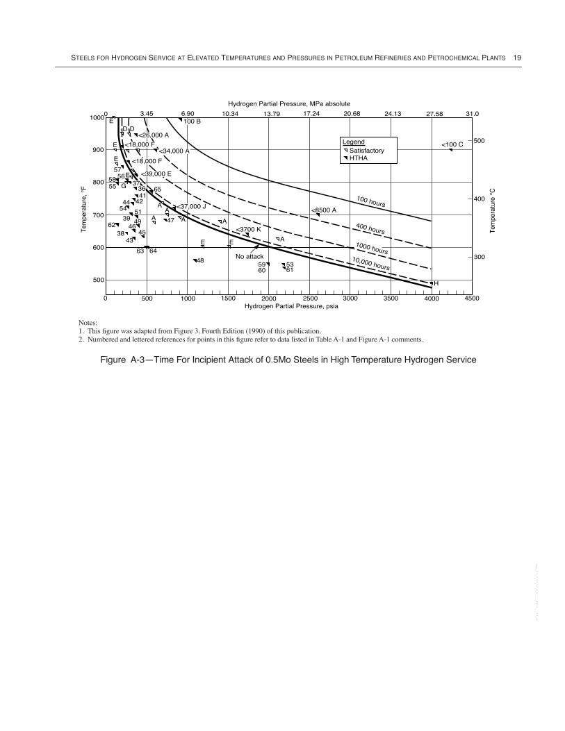
STEELS FOR HYDROGEN SERVICE AT ELEVATED TEMPERATURES AND PRESSURES IN PETROLEUM REFINERIES AND PETROCHEMICAL PLANTS 19
Figure A-3ÑTime For Incipient Attack of 0.5Mo Steels in High Temperature Hydrogen Service
500
600
700
800
<26,000 A
Tem
pera
ture
, ¡F
300
400
500
Tem
pera
ture
¡C
3.45 13.7910.34 17.24 20.68 24.136.90 27.58 31.0
Hydrogen Partial Pressure, MPa absolute
1000
450040003500300025002000150010000Hydrogen Partial Pressure, psia
100 B0
<18,000 F<34,000 A
<18,000 F
<39,000 E
<37,000 J
900
500 H
<100 C
<8500 A
A
536160
59
<3700 KA
EE
48
64
62
65
54
63No attack
ED D
E
E
G
E37
3641
4244 AA
47 A3951
49
4538
57
5855
56
46
43
A
LegendSatisfactoryHTHA
100 hours
400 hours
1000 hours10,000 hours
Notes:1. This Þgure was adapted from Figure 3, Fourth Edition (1990) of this publication.2. Numbered and lettered references for points in this Þgure refer to data listed in Table A-1 and Figure A-1 comments.
--`,,```,,,,````-`-`,,`,,`,`,,`---

--`,,```,,,,````-`-`,,`,,`,`,,`---
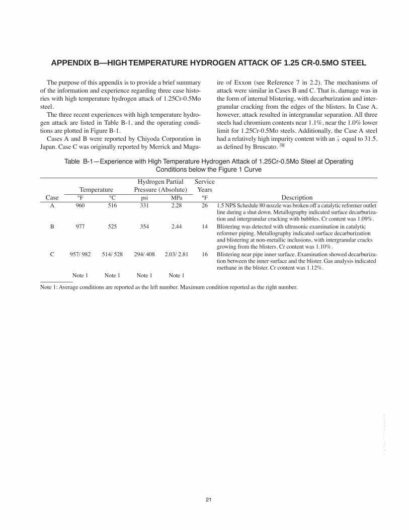
21
APPENDIX B—HIGH TEMPERATURE HYDROGEN ATTACK OF 1.25 CR-0.5MO STEEL
The purpose of this appendix is to provide a brief summaryof the information and experience regarding three case histo-ries with high temperature hydrogen attack of 1.25Cr-0.5Mosteel.
The three recent experiences with high temperature hydro-gen attack are listed in Table B-1, and the operating condi-tions are plotted in Figure B-1.
Cases A and B were reported by Chiyoda Corporation inJapan. Case C was originally reported by Merrick and Magu-
ire of Exxon (see Reference 7 in 2.2). The mechanisms ofattack were similar in Cases B and C. That is, damage was inthe form of internal blistering, with decarburization and inter-granular cracking from the edges of the blisters. In Case A,however, attack resulted in intergranular separation. All threesteels had chromium contents near 1.1%, near the 1.0% lowerlimit for 1.25Cr-0.5Mo steels. Additionally, the Case A steelhad a relatively high impurity content with an equal to 31.5,as deÞned by Bruscato. 38
x
Table B-1ÑExperience with High Temperature Hydrogen Attack of 1.25Cr-0.5Mo Steel at Operating Conditions below the Figure 1 Curve
TemperatureHydrogen Partial
Pressure (Absolute)ServiceYears
Case ¡F ¡C psi MPa ¡F DescriptionA 960 516 331 2.28 26 1.5 NPS Schedule 80 nozzle was broken off a catalytic reformer outlet
line during a shut down. Metallography indicated surface decarburiza-tion and intergranular cracking with bubbles. Cr content was 1.09%.
B 977 525 354 2.44 14 Blistering was detected with ultrasonic examination in catalytic reformer piping. Metallography indicated surface decarburization and blistering at non-metallic inclusions, with intergranular cracks growing from the blisters. Cr content was 1.10%.
C 957/ 982 514/ 528 294/ 408 2.03/ 2.81 16 Blistering near pipe inner surface. Examination showed decarburiza-tion between the inner surface and the blister. Gas analysis indicated methane in the blister. Cr content was 1.12%.
Note 1 Note 1 Note 1 Note 1
Note 1: Average conditions are reported as the left number. Maximum condition reported as the right number.
--`,,```,,,,````-`-`,,`,,`,`,,`---
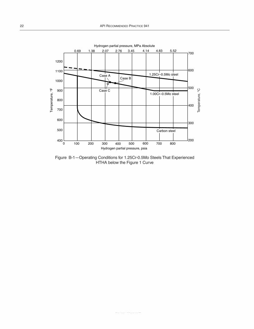
22 API RECOMMENDED PRACTICE 941
Figure B-1ÑOperating Conditions for 1.25Cr-0.5Mo Steels That Experienced HTHA below the Figure 1 Curve
1000 200 300 400 500 600 700 800400
900
1000
1100
1200
700
600
500
800
Hydrogen partial pressure, psia
700
300
400
200
600
500
3.452.762.071.380.69 4.14 4.83 5.52
Case B
Case C
1.25CrÐ0.5Mo steel
1.00CrÐ0.5Mo steel
Case A
Hydrogen partial pressure, MPa Absolute
Carbon steel
--`,,```,,,,````-`-`,,`,,`,`,,`---
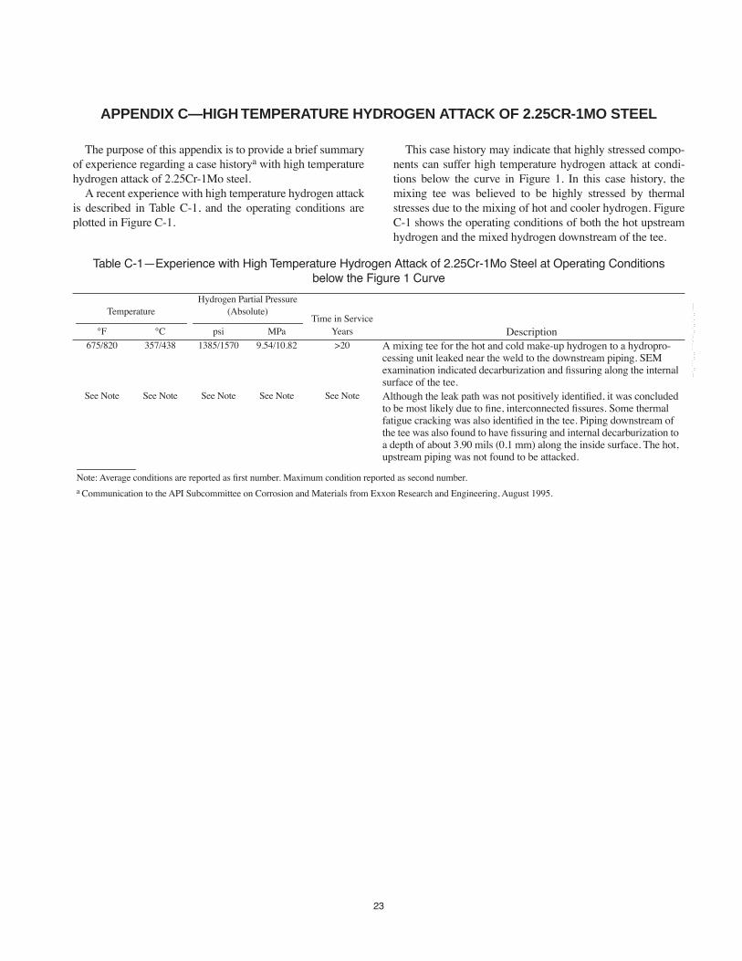
23
APPENDIX C—HIGH TEMPERATURE HYDROGEN ATTACK OF 2.25CR-1MO STEEL
The purpose of this appendix is to provide a brief summaryof experience regarding a case historya with high temperaturehydrogen attack of 2.25Cr-1Mo steel.
A recent experience with high temperature hydrogen attackis described in Table C-1, and the operating conditions areplotted in Figure C-1.
This case history may indicate that highly stressed compo-nents can suffer high temperature hydrogen attack at condi-tions below the curve in Figure 1. In this case history, themixing tee was believed to be highly stressed by thermalstresses due to the mixing of hot and cooler hydrogen. FigureC-1 shows the operating conditions of both the hot upstreamhydrogen and the mixed hydrogen downstream of the tee.
Table C-1ÑExperience with High Temperature Hydrogen Attack of 2.25Cr-1Mo Steel at Operating Conditions below the Figure 1 Curve
TemperatureHydrogen Partial Pressure
(Absolute)Time in Service
¡F ¡C psi MPa Years Description675/820 357/438 1385/1570 9.54/10.82 >20 A mixing tee for the hot and cold make-up hydrogen to a hydropro-
cessing unit leaked near the weld to the downstream piping. SEM examination indicated decarburization and Þssuring along the internal surface of the tee.
See Note See Note See Note See Note See Note Although the leak path was not positively identiÞed, it was concluded to be most likely due to Þne, interconnected Þssures. Some thermal fatigue cracking was also identiÞed in the tee. Piping downstream of the tee was also found to have Þssuring and internal decarburization to a depth of about 3.90 mils (0.1 mm) along the inside surface. The hot, upstream piping was not found to be attacked.
Note: Average conditions are reported as Þrst number. Maximum condition reported as second number.a Communication to the API Subcommittee on Corrosion and Materials from Exxon Research and Engineering, August 1995.
--`,,```,,,,````-`-`,,`,,`,`,,`---
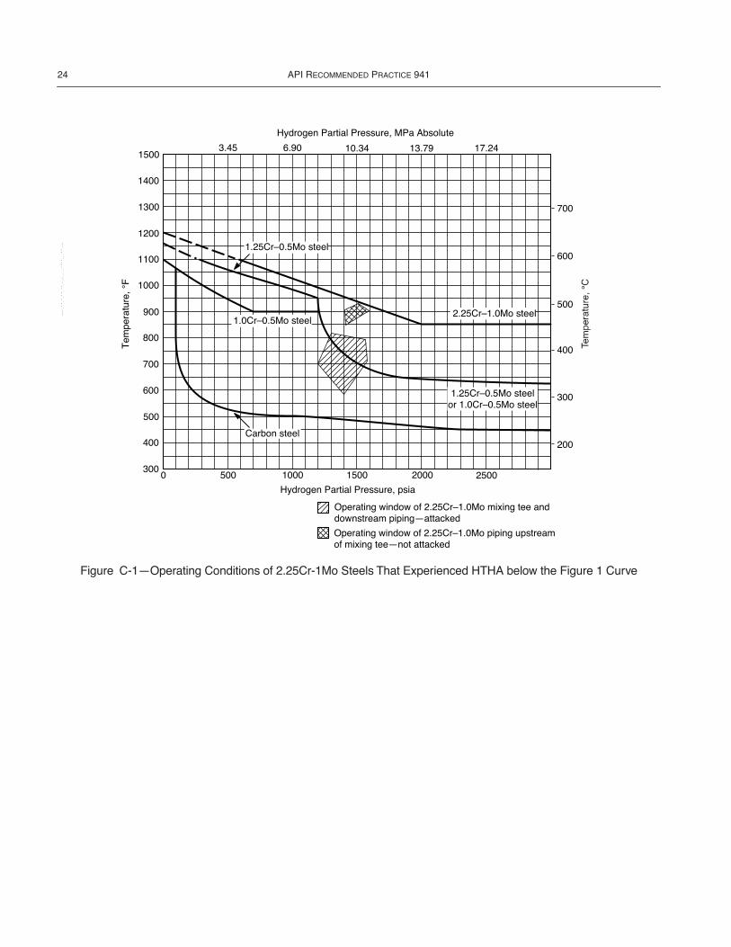
24 API RECOMMENDED PRACTICE 941
Figure C-1ÑOperating Conditions of 2.25Cr-1Mo Steels That Experienced HTHA below the Figure 1 Curve
1500
1400
1300
1200
1100
1000
800
900
700
600
500
400
300
3.45 6.90 10.34 13.79 17.24
700
600
500
400
300
200
Hydrogen Partial Pressure, MPa Absolute
0 500 1000 1500 2000 2500
1.0CrÐ0.5Mo steel
Hydrogen Partial Pressure, psia
Operating window of 2.25CrÐ1.0Mo mixing tee anddownstream pipingÑattacked
Operating window of 2.25CrÐ1.0Mo piping upstreamof mixing teeÑnot attacked
2.25CrÐ1.0Mo steel
1.25CrÐ0.5Mo steelor 1.0CrÐ0.5Mo steel
Carbon steel
1.25CrÐ0.5Mo steel
--`,,```,,,,````-`-`,,`,,`,`,,`---

25
APPENDIX D
--`,,```,,,,````-`-`,,`,,`,`,,`---
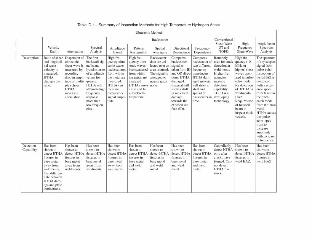
Table D-1ÑSummary of Inspection Methods for High Temperature Hydrogen Attack
Ultrasonic Methods
Velocity Ratio Attenuation
Spectral Analysis
Backscatter Conventional Shear Wave
UT and TOFD
High Frequency Shear Wave
Angle-beam Spectrum Analysis
Amplitude Based
Pattern Recognition
Spatial Averaging
Directional Dependence
Frequency Dependence
Description Ratio of shear and longitudi-nal wave velocity is measured. HTHA changes the ratio.
Dispersion of ultrasonic shear wave is measured by recording drop in ampli-tude of multi-ple echoes. HTHA increases attenuation.
The Þrst backwall sig-nal is ana-lyzed in terms of amplitude versus fre-quency. HTHA will attenuate high frequency response more than low frequen-cies.
High fre-quency ultra-sonic waves backscattered from within the metal are measured. HTHA can increase backscatter signal ampli-tude.
High fre-quency ultra-sonic waves backscattered from within the metal are analyzed. HTHA causes a rise and fall in backscat-ter pattern.
Backscatter data are col-lected over an area scanned. The signal is averaged to negate grain noise.
Compares backscatter signal as taken from ID and OD direc-tions. HTHA damaged material will show a shift in indicated damage towards the exposed sur-face (ID).
Compares backscatter of two different frequency transducers. HTHA dam-aged material will show a shift and spread of backscatter in time.
Routinely used for crack detection at weldments. Higher fre-quencies increase detection capability. TOFD is a developing technology.
High fre-quency (10 MHz or higher) shear waves oper-ated in pulse-echo mode for detection of HTHA in weldments/HAZ. Requires use of focused beam to inspect thick vessels.
The spectrum of any suspect signal from pulse-echo inspection of weld/HAZ is compared with a refer-ence spec-trum taken in the pitch-catch mode from the base metal. HTHA causes the pulse-echo spec-trum to increase amplitude with increase of frequency.
Detection Capability
Has been shown to detect HTHA Þssures in base metal, away from weldments. Can differen-tiate between HTHA dam-age and plate laminations.
Has been shown to detect HTHA Þssures in base metal away from weldments.
Has been shown to detect HTHA Þssures in base metal away from weldments.
Has been shown to detect HTHA Þssures in base metal away from weldments.
Has been shown to detect HTHA Þssures in base metal and weld metal.
Has been shown to detect HTHA Þssures in base metal and weld metal.
Has been shown to detect HTHA Þssures in base metal and weld metal.
Has been shown to detect HTHA Þssures in base metal and weld metal.
Can reliably detect HTHA only after cracks have formed. Can-not detect HTHA Þs-sures.
Has been shown to detect HTHA Þssures in weld HAZ.
Has been shown to detect HTHA Þssures in weld HAZ.
--`,,```,,,,````-`-`,,`,,`,`,,`---

ST
EE
LS FO
R HY
DR
OG
EN S
ER
VIC
E AT E
LEV
AT
ED T
EM
PE
RA
TU
RE
S AN
D PR
ES
SU
RE
S IN PE
TR
OLE
UM
RE
FIN
ER
IES A
ND P
ET
RO
CH
EM
ICA
L PLA
NT
S27
Advantages Not affected by inclu-sions, grain size, or sur-face rough-ness, or curvature. No prior inspec-tion history needed for interpretation.
Simple to use. Very sensi-tive to inter-nal Þssuring due to HTHA. Can be used to differentiate between inclusions and HTHA damage.
Very sensi-tive to inter-nal Þssuring due to HTHA. Can be used for scanning. Can give an indi-cation of depth of HTHA. Can be automated in either a B-scan or C-scan mode. Can be used to monitor changes in extent of damage.
Very sensi-tive to inter-nal Þssuring due to HTHA. Can be used for scanning. Can give an indi-cation of depth of HTHA. Can differentiate between HTHA dam-age and inclu-sions.
Sensitive to internal Þs-suring due to HTHA. Can be used to improve detection of Þssuring stages of HTHA and to determine depth of dam-age.
Very sensi-tive to inter-nal Þssuring due to HTHA. Can be used to dif-ferentiate between HTHA dam-age and other internal defects such as inclusions.
Very sensi-tive to inter-nal Þssuring due to HTHA. Can be used to dif-ferentiate between HTHA dam-age and other internal defects such as inclusions.
Can scan full coverage of weldments from the OD.
Can scan full coverage of weldments from the OD. Very sensi-tive to inter-nal Þssuring due to HTHA. Can be used to dif-ferentiate between HTHA dam-age and weld-ing defects and inclu-sions. Can be used for scan-ning. Can give an indi-cation of depth of HTHA. Can be automated in either a B-scan or C-scan mode. Can be used to monitor changes in extent of damage.
Can scan full coverage of weldments from the OD. Very sensi-tive to inter-nal Þssuring due to HTHA. Can be used to dif-ferentiate between HTHA dam-age and weld-ing defects and inclu-sions.
Table D-1ÑSummary of Inspection Methods for High Temperature Hydrogen Attack (Continued)
Ultrasonic Methods
Velocity Ratio Attenuation
Spectral Analysis
Backscatter Conventional Shear Wave
UT and TOFD
High Frequency Shear Wave
Angle-beam Spectrum Analysis
Amplitude Based
Pattern Recognition
Spatial Averaging
Directional Dependence
Frequency Dependence
--`,,```,,,,````-`-`,,`,,`,`,,`---
28A
PI S
TA
ND
AR
D 941
Limitations Covers only local spot where probe is held. Can-not be used for scanning large areas. Cannot detect HTHA dam-age that is less than 10% through wall. Cladding can cause false interpretation if included in velocity mea-surement.
Covers only local spot where probe is held. Can-not be used for scanning. ID or OD sur-face corrosion can give false readings. Needs paral-lel surfaces. Thick materi-als decrease sensitivity. DifÞcult to get similar repeat read-ings when used as a monitoring program.
Technique is best when used as a comparison of a clean non-HTHA area versus a suspect area.
Inclusions, large grains, ID pitting, laminar defects, or scale can give false indica-tions of HTHA. Dam-age from HTHA atten-uates back-scatter signal, which can cause false interpreta-tions in siz-ing and characteriz-ing the ßaw.
Not a pri-mary method, usually a complemen-tary method.
Requires access to both ID and OD surfaces. Does not work well on clad equip-ment.
Not a pri-mary method, usually a complemen-tary method. Does not work well on very shallow HTHA dam-age.
Cannot detect HTHA Þs-sures. Can only detect HTHA cracks. Actual crack sizing can be difÞcult.
Accurately sizing the depth of HTHA Þs-sures in weld HAZ may be difÞcult.
Recommen-dations
Recom-mended for base metal HTHA detec-tion when 1) advanced HTHA dam-age is sug-gested by the results of other methods or 2) used as a complemen-tary technique with a back-scatter method.
Not recom-mended for HTHA inspection.
Used as a complemen-tary technique after back-scatter method indi-cates possi-ble damage.
Recom-mended only when used with other techniques. Should be limited to the initial screen-ing.
Recom-mended only when used with other techniques as the Þrst step of inspection.
Used as a complemen-tary technique when depth of damage can-not be clearly identiÞed.
Used as a complemen-tary technique after back-scatter pat-tern recognition technique indicates pos-sible damage.
Used as a complemen-tary technique after back-scatter pat-tern recognition technique indicates pos-sible damage.
Not recom-mended for HTHA inspection to detect Þs-sures. Can be used to detect developed cracks.
Recom-mended for detection and sizing of localized HTHA in weld/HAZ.
Recom-mended as a complemen-tary technique after high fre-quency shear wave indi-cates possi-ble damage.
Table D-1ÑSummary of Inspection Methods for High Temperature Hydrogen Attack (Continued)
Ultrasonic Methods
Velocity Ratio Attenuation
Spectral Analysis
Backscatter Conventional Shear Wave
UT and TOFD
High Frequency Shear Wave
Angle-beam Spectrum Analysis
Amplitude Based
Pattern Recognition
Spatial Averaging
Directional Dependence
Frequency Dependence
--`,,```,,,,````-`-`,,`,,`,`,,`---
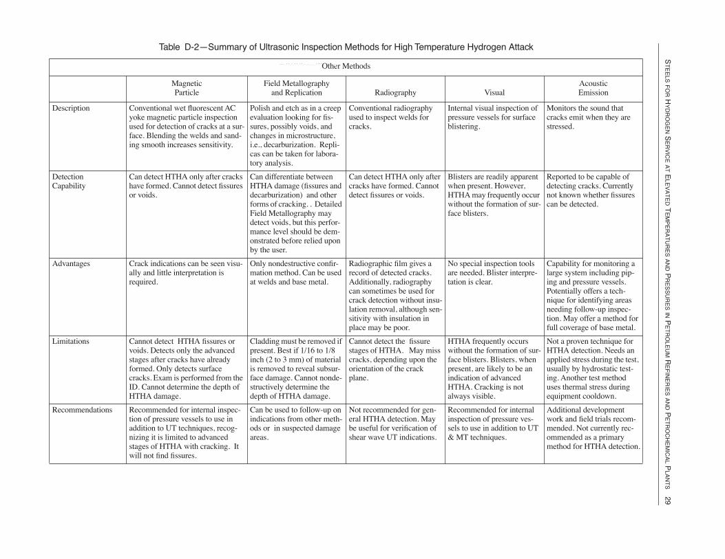
ST
EE
LS FO
R HY
DR
OG
EN S
ER
VIC
E AT E
LEV
AT
ED T
EM
PE
RA
TU
RE
S AN
D PR
ES
SU
RE
S IN PE
TR
OLE
UM
RE
FIN
ER
IES A
ND P
ET
RO
CH
EM
ICA
L PLA
NT
S29
Table D-2ÑSummary of Ultrasonic Inspection Methods for High Temperature Hydrogen Attack
Other Methods
Magnetic Particle
Field Metallography and Replication Radiography Visual
Acoustic Emission
Description Conventional wet ßuorescent AC yoke magnetic particle inspection used for detection of cracks at a sur-face. Blending the welds and sand-ing smooth increases sensitivity.
Polish and etch as in a creep evaluation looking for Þs-sures, possibly voids, and changes in microstructure, i.e., decarburization. Repli-cas can be taken for labora-tory analysis.
Conventional radiography used to inspect welds for cracks.
Internal visual inspection of pressure vessels for surface blistering.
Monitors the sound that cracks emit when they are stressed.
Detection Capability
Can detect HTHA only after cracks have formed. Cannot detect Þssures or voids.
Can differentiate between HTHA damage (Þssures and decarburization) and other forms of cracking. . Detailed Field Metallography may detect voids, but this perfor-mance level should be dem-onstrated before relied upon by the user.
Can detect HTHA only after cracks have formed. Cannot detect Þssures or voids.
Blisters are readily apparent when present. However, HTHA may frequently occur without the formation of sur-face blisters.
Reported to be capable of detecting cracks. Currently not known whether Þssures can be detected.
Advantages Crack indications can be seen visu-ally and little interpretation is required.
Only nondestructive conÞr-mation method. Can be used at welds and base metal.
Radiographic Þlm gives a record of detected cracks. Additionally, radiography can sometimes be used for crack detection without insu-lation removal, although sen-sitivity with insulation in place may be poor.
No special inspection tools are needed. Blister interpre-tation is clear.
Capability for monitoring a large system including pip-ing and pressure vessels. Potentially offers a tech-nique for identifying areas needing follow-up inspec-tion. May offer a method for full coverage of base metal.
Limitations Cannot detect HTHA Þssures or voids. Detects only the advanced stages after cracks have already formed. Only detects surface cracks. Exam is performed from the ID. Cannot determine the depth of HTHA damage.
Cladding must be removed if present. Best if 1/16 to 1/8 inch (2 to 3 mm) of material is removed to reveal subsur-face damage. Cannot nonde-structively determine the depth of HTHA damage.
Cannot detect the Þssure stages of HTHA. May miss cracks, depending upon the orientation of the crack plane.
HTHA frequently occurs without the formation of sur-face blisters. Blisters, when present, are likely to be an indication of advanced HTHA. Cracking is not always visible.
Not a proven technique for HTHA detection. Needs an applied stress during the test, usually by hydrostatic test-ing. Another test method uses thermal stress during equipment cooldown.
Recommendations Recommended for internal inspec-tion of pressure vessels to use in addition to UT techniques, recog-nizing it is limited to advanced stages of HTHA with cracking. It will not Þnd Þssures.
Can be used to follow-up on indications from other meth-ods or in suspected damage areas.
Not recommended for gen-eral HTHA detection. May be useful for veriÞcation of shear wave UT indications.
Recommended for internal inspection of pressure ves-sels to use in addition to UT & MT techniques.
Additional development work and Þeld trials recom-mended. Not currently rec-ommended as a primary method for HTHA detection.
--`,,```,,,,````-`-`,,`,,`,`,,`---

--`,,```,,,,````-`-`,,`,,`,`,,`---
31
APPENDIX E—REQUEST FOR NEW INFORMATION
The API Subcommittee on Corrosion and Materials col-lects data on the alloys shown in all Þgures or similar alloysthat may come into use. Revisions to the curves will be pub-lished as the need arises.
For the existing curves, data are desired for instances ofhigh temperature hydrogen attack (HTHA) damage thatoccur above or below the curve for the steel involved; dataare also desired for successful experience in the area abovethe curve for the steel involved. For chromium-molybdenumsteels not included on the existing Þgures, data for successesand HTHA damage in any meaningful area are desired.
The following data sheet is provided for the readerÕs con-venience in submitting new data. Available data should befurnished by inserting information in the spaces provided
and checking the appropriate answer where a selection isindicated. Any additional information should be attached.
While both hydrogen partial pressure and temperature areimportant, particular attention should be given to obtainingthe best estimate of accurate metal temperature. Onemethod of obtaining more accurate data for a speciÞc area isto attach a skin thermocouple to the area that previouslyexhibited high temperature hydrogen damage.
The completed form should be returned to the followingaddress:
American Petroleum InstituteStandards Department1220 L Street, N.W.Washington, D.C. [email protected]
--`,,```,,,,````-`-`,,`,,`,`,,`---
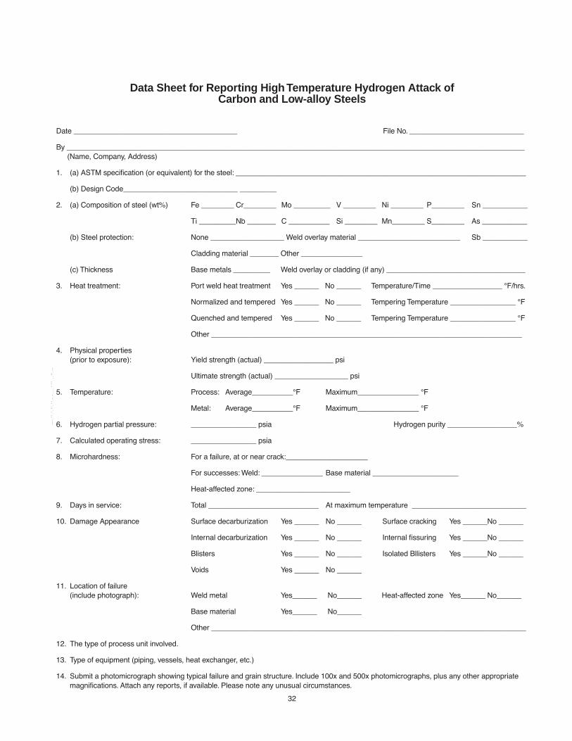
32
Data Sheet for Reporting High Temperature Hydrogen Attack of Carbon and Low-alloy Steels
Date ________________________________________ File No. ____________________________
By ________________________________________________________________________________________________________________(Name, Company, Address)
1. (a) ASTM speciÞcation (or equivalent) for the steel: _______________________________________________________________________
(b) Design Code____________________________ _________
2. (a) Composition of steel (wt%) Fe ________ Cr________ Mo _________ V ________ Ni ________ P________ Sn ___________
Ti _________Nb _______ C __________ Si ________ Mn________ S________ As ___________
(b) Steel protection: None __________________ Weld overlay material _________________________ Sb ___________
Cladding material _______ Other _______________
(c) Thickness Base metals _________ Weld overlay or cladding (if any) __________________________________
3. Heat treatment: Port weld heat treatment Yes ______ No ______ Temperature/Time _________________ ¡F/hrs.
Normalized and tempered Yes ______ No ______ Tempering Temperature ________________ ¡F
Quenched and tempered Yes ______ No ______ Tempering Temperature ________________ ¡F
Other ____________________________________________________________________________
4. Physical properties(prior to exposure): Yield strength (actual) _________________ psi
Ultimate strength (actual) __________________ psi
5. Temperature: Process: Average__________¡F Maximum_______________ ¡F
Metal: Average__________¡F Maximum_______________ ¡F
6. Hydrogen partial pressure: ________________ psia Hydrogen purity _________________%
7. Calculated operating stress: ________________ psia
8. Microhardness: For a failure, at or near crack:____________________
For successes: Weld: _______________ Base material _____________________
Heat-affected zone: _______________________
9. Days in service: Total ___________________________ At maximum temperature ____________________________
10. Damage Appearance Surface decarburization Yes ______ No ______ Surface cracking Yes ______No ______
Internal decarburization Yes ______ No ______ Internal Þssuring Yes ______No ______
Blisters Yes ______ No ______ Isolated Bllisters Yes ______No ______
Voids Yes ______ No ______
11. Location of failure(include photograph): Weld metal Yes______ No______ Heat-affected zone Yes______ No______
Base material Yes______ No______
Other _____________________________________________________________________________
12. The type of process unit involved.
13. Type of equipment (piping, vessels, heat exchanger, etc.)
14. Submit a photomicrograph showing typical failure and grain structure. Include 100x and 500x photomicrographs, plus any other appropriate magniÞcations. Attach any reports, if available. Please note any unusual circumstances.
--`,,```,,,,````-`-`,,`,,`,`,,`---
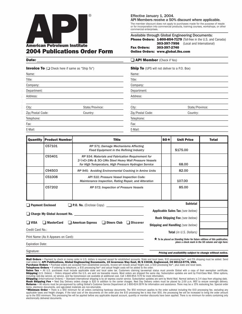
Invoice To (❏ Check here if same as “Ship To”)
Name:
Title:
Company:
Department:
Address:
City: State/Province:
Zip/Postal Code: Country:
Telephone:
Fax:
E-Mail:
❏ Payment Enclosed ❏ P.O. No. (Enclose Copy)
❏ Charge My Global Account No.
❏ VISA ❏ MasterCard ❏ American Express ❏ Diners Club ❏ Discover
Credit Card No.:
Print Name (As It Appears on Card):
Expiration Date:
Signature:
Quantity Product Number Title Total
Subtotal
Applicable Sales Tax (see below)
Rush Shipping Fee (see below)
Shipping and Handling (see below)
Total (in U.S. Dollars)
★ To be placed on Standing Order for future editions of this publication,place a check mark in the SO column and sign here:
Pricing and availability subject to change without notice.
Date:
SO★ Unit Price
❏ API Member (Check if Yes)
Ship To (UPS will not deliver to a P.O. Box)
Name:
Title:
Company:
Department:
Address:
City: State/Province:
Zip/Postal Code: Country:
Telephone:
Fax:
E-Mail:
Mail Orders – Payment by check or money order in U.S. dollars is required except for established accounts. State and local taxes, $10 processing fee*, and 5% shipping must be added. Sendmail orders to: API Publications, Global Engineering Documents, 15 Inverness Way East, M/S C303B, Englewood, CO 80112-5776, USA.Purchase Orders – Purchase orders are accepted from established accounts. Invoice will include actual freight cost, a $10 processing fee*, plus state and local taxes.Telephone Orders – If ordering by telephone, a $10 processing fee* and actual freight costs will be added to the order.Sales Tax – All U.S. purchases must include applicable state and local sales tax. Customers claiming tax-exempt status must provide Global with a copy of their exemption certificate.Shipping (U.S. Orders) – Orders shipped within the U.S. are sent via traceable means. Most orders are shipped the same day. Subscription updates are sent by First-Class Mail. Other options,including next-day service, air service, and fax transmission are available at additional cost. Call 1-800-854-7179 for more information.Shipping (International Orders) – Standard international shipping is by air express courier service. Subscription updates are sent by World Mail. Normal delivery is 3-4 days from shipping date.Rush Shipping Fee – Next Day Delivery orders charge is $20 in addition to the carrier charges. Next Day Delivery orders must be placed by 2:00 p.m. MST to ensure overnight delivery.Returns – All returns must be pre-approved by calling Global’s Customer Service Department at 1-800-624-3974 for information and assistance. There may be a 15% restocking fee. Special orderitems, electronic documents, and age-dated materials are non-returnable.*Minimum Order – There is a $50 minimum for all orders containing hardcopy documents. The $50 minimum applies to the order subtotal including the $10 processing fee, excluding anyapplicable taxes and freight charges. If the total cost of the documents on the order plus the $10 processing fee is less than $50, the processing fee will be increased to bring the order amountup to the $50 minimum. This processing fee will be applied before any applicable deposit account, quantity or member discounts have been applied. There is no minimum for orders containing onlyelectronically delivered documents.
Effective January 1, 2004.API Members receive a 50% discount where applicable.The member discount does not apply to purchases made for the purpose of resale or for incorporation into commercial products, training courses, workshops, or othercommercial enterprises.
Available through Global Engineering Documents:Phone Orders: 1-800-854-7179 (Toll-free in the U.S. and Canada)
303-397-7956 (Local and International)Fax Orders: 303-397-2740Online Orders: www.global.ihs.com
®APIAmerican Petroleum Institute2004 Publications Order Form
C57101 RP 571; Damage Mechanisms AffectingFixed Equipment in the Refining Industry $175.00
C93401 RP 934; Materials and Fabrication Requirement for2-1/4Cr-1Mo & 3Cr-1Mo Steel Heavy Wall Pressure Vessels
for High Temperature, High Pressure Hydrogen Service 68.00
C94503 RP 945; Avoiding Environmental Cracking in Amine Units 82.00
C51008 API 510; Pressure Vessel Inspection Code: Maintenance Inspection, Rating Repair, and Alteration 107.00
C57202 RP 572; Inspection of Pressure Vessels 85.00
--`,,```,,,,````-`-`,,`,,`,`,,`---

There’s more where this came from.The American Petroleum Institute provides additional resources and programsto the oil and natural gas industry which are based on API® Standards. Formore information, contact:
• API Monogram® Licensing Program Phone: 202-962-4791Fax: 202-682-8070
• American Petroleum Institute Quality Registrar Phone: 202-962-4791(APIQR®) Fax: 202-682-8070
• API Spec Q1® Registration Phone: 202-962-4791Fax: 202-682-8070
• API Perforator Design Registration Phone: 202-962-4791Fax: 202-682-8070
• API Training Provider Certification Program Phone: 202-682-8490Fax: 202-682-8070
• Individual Certification Programs Phone: 202-682-8064Fax: 202-682-8348
• Engine Oil Licensing and Certification System Phone: 202-682-8516(EOLCS) Fax: 202-962-4739
• API PetroTEAM™ Phone: 202-682-8195(Training, Education and Meetings) Fax: 202-682-8222
Check out the API Publications, Programs, and Services Catalog online atwww.api.org.
APIAmerican Petroleum Institute Helping You Get The Job Done Right.®
®
--`,,```,,,,````-`-`,,`,,`,`,,`---

03/04
--`,,```,,,,````-`-`,,`,,`,`,,`---

Additional copies are available through Global EngineeringDocuments at (800) 854-7179 or (303) 397-7956
Information about API Publications, Programs and Services isavailable on the World Wide Web at: http://www.api.org
Product No. C94106--`,,```,,,,````-`-`,,`,,`,`,,`---


![[INCO 2980]Austenitic Chromium-Nickel Stainless Steels at Elevated Temperatures Mechanical and Physical Properties](https://img.dokumen.tips/doc/110x75/577cd8e81a28ab9e78a245c9/inco-2980austenitic-chromium-nickel-stainless-steels-at-elevated-temperatures.jpg)


