Embed Size (px)
Citation preview

750 W. Lake Cook Rd., Suite 480 | Buffalo Grove, IL 60089
Ph: 855.572.6849
www.concretefibersolutions.com
STEEL DECK? STEEL FIBERS!
The most common concrete floor type is the ground-supported slab, also known as slab on
ground or slab on grade. Second in popularity, at least in North America, comes the composite
slab, a type of suspended floor made of concrete over a steel deck. The two floor types have
several things in common. Both are widely used; both are often misunderstood; and both
benefit from steel fibers. However, steel fibers play a different role in each floor type.
DEFINING TERMS
You who are structural engineers may want to skip this section.
A composite slab is a suspended floor that consists of concrete cast over a deck of corrugated
sheet steel. The concrete doesn't just sit on top of the steel deck, but is tightly connected to it,
usually through dimples pressed into the steel. The dimples work like the deformations on
rebar, connecting concrete and steel to make a composite structural element (Fig. 1).
Figure 1. Steel deck designed for a composite slab. Corrugations make the deck stiff. Dimples connect the deck to the concrete slab, allowing composite action. This particular deck is W3 Formlok from Verco Decking, Inc. Other
manufacturers may use different shapes but the principles, including the benefits of steel fibers, remain the same.

750 W. Lake Cook Rd., Suite 480 | Buffalo Grove, IL 60089
Ph: 855.572.6849
www.concretefibersolutions.com
Composite slabs go by several names. The Steel Deck Institute calls them composite steel floor
deck-slabs, which is quite a mouthful. Out on the jobsite, they are often known as slabs on
deck. That last term, though valid and concise, can be misleading -- because not every slab on
deck is composite. There are also noncomposite floors in which the steel deck serves only as a
soffit form that is left in place. Such floors are designed as normal reinforced concrete slabs
with internal reinforcement. The steel deck under a noncomposite slab is called a form deck,
and it lacks the dimples that create composite action. I won't say any more about
noncomposite slabs here, but you should know they exist.
The reinforcement in composite slabs is often classified as positive or negative. These terms
have different meanings in structural engineering than they do in everyday speech. Positive
reinforcement resists the tension caused by positive moment; negative reinforcement resists
the tension caused by negative moment. In a floor slab, positive moment is the sagging that
occurs between supports. Sagging puts the slab in tension at the bottom, so positive
reinforcement goes in the lower part of the slab. Negative moment is the hogging that occurs
over a support. Hogging puts the slab in tension at the top, so negative reinforcement goes in
the upper part of the slab.
THREE KINDS OF REINFORCEMENT
Composite slabs contain three distinct kinds of reinforcement: positive, negative, and crack-
control. But not every floor gets all three.
Positive reinforcement, in every composite slab, is the steel deck. Located at the very bottom
of the slab, it is in the ideal place to resist positive moment. Some designs include rebar near
the bottom for extra positive reinforcement, but this is an addition to, not a replacement for,
the steel deck.
Negative reinforcement normally consists of short lengths of rebar placed high in the slab,
centered over the structural supports. Not every composite slab needs negative reinforcement.
If the floor is what engineers call a simply supported span -- a single span with a support at each
end -- there is no negative moment to worry about. Only floors with multiple spans experience
negative moment, and even their designers may choose to treat each span as if it were simply
supported, eliminating the need for negative reinforcement as a key part of the structural
design.
750 W. Lake Cook Rd., Suite 480 | Buffalo Grove, IL 60089
Ph: 855.572.6849
www.concretefibersolutions.com
Crack-control reinforcement deals with cracks that occur for any reason other than positive and
negative moments. Because these nonstructural cracks are most often caused by temperature
changes and concrete's drying shrinkage, they are sometimes called temperature and shrinkage
cracks. They do not affect the floor's ability to support loads, but they can look bad and reduce
a floor's serviceability if they grow too wide. Crack-control reinforcement aims not to prevent
nonstructural cracks, but to limit their width.
The role of steel fibers in a composite steel-deck slab is normally confined to the third kind of
reinforcement: crack-control. You don't need steel fibers for positive reinforcement because
the steel deck does that job. You could, conceivably, use steel fibers for negative
reinforcement, but rebar is generally more efficient for this purpose, because you can confine it
to the locations of high negative moment instead of spreading it throughout the slab.
WIRE MESH -- TRADITIONAL BUT FLAWED
Traditionally, designers have specified wire mesh to control cracks in composite slabs. The
Steel Deck Institute has long endorsed this practice, calling for steel equal to at least 0.075% of
the slab's cross-sectional area (The area is measured above the deck flutes.).1 Some engineers
call for more than the minimum, up to eight times as much, hoping to keep cracks tighter than
usual.
Wire mesh works -- if it is lapped properly, and if it is supported high in the slab so it can limit
crack width at the floor surface. But those are big ifs that often go unsatisfied. It turns out that
wire mesh suffers from five serious drawbacks.
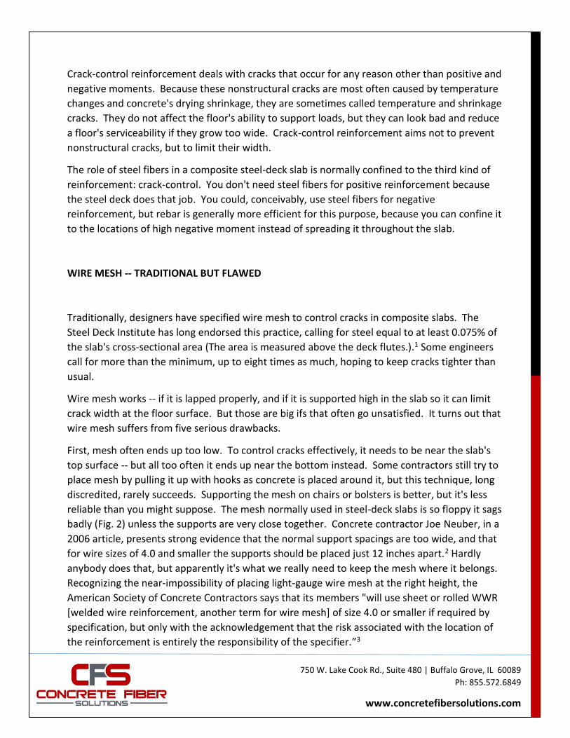
First, mesh often ends up too low. To control cracks effectively, it needs to be near the slab's
top surface -- but all too often it ends up near the bottom instead. Some contractors still try to
place mesh by pulling it up with hooks as concrete is placed around it, but this technique, long
discredited, rarely succeeds. Supporting the mesh on chairs or bolsters is better, but it's less
reliable than you might suppose. The mesh normally used in steel-deck slabs is so floppy it sags
badly (Fig. 2) unless the supports are very close together. Concrete contractor Joe Neuber, in a
2006 article, presents strong evidence that the normal support spacings are too wide, and that
for wire sizes of 4.0 and smaller the supports should be placed just 12 inches apart.2 Hardly
anybody does that, but apparently it's what we really need to keep the mesh where it belongs.
Recognizing the near-impossibility of placing light-gauge wire mesh at the right height, the
American Society of Concrete Contractors says that its members "will use sheet or rolled WWR
[welded wire reinforcement, another term for wire mesh] of size 4.0 or smaller if required by
specification, but only with the acknowledgement that the risk associated with the location of
the reinforcement is entirely the responsibility of the specifier.”3
750 W. Lake Cook Rd., Suite 480 | Buffalo Grove, IL 60089
Ph: 855.572.6849
www.concretefibersolutions.com
Figure 2. Wire mesh sagging between supports. I bet it doesn't look like this on the drawings.
Second, mesh sometimes ends up too high. Though it's rare for a whole mat to be installed too
high, often a corner will stick up above the floor surface. If the concrete finishers catch this in
time, they can snip off the offending wires with bolt cutters, but that's messy. If they don't
catch it in time, wires must be cut out of the hardened concrete, leaving damage that must be
patched.
Third, mesh comes in sheets that must be lapped to provide continuous reinforcement.
Specifications typically call for a minimum lap of one space (the distance between cross wires)
plus 2 inches. The Wire Reinforcement Institute recommends tying the sheets together at all
laps, though that advice is often ignored.4 If the mesh shifts before or during the concrete pour,
the laps can easily disappear, leaving gaps where cracks can open wide. And even if the mesh
doesn't shift, laps can cause trouble. With some layouts, you end up with locations where four
layers overlap. That's a lot of wire to cram into what can be a tight space, and it can lead to the
problem mentioned in the previous paragraph: mesh sticking out of the floor surface.
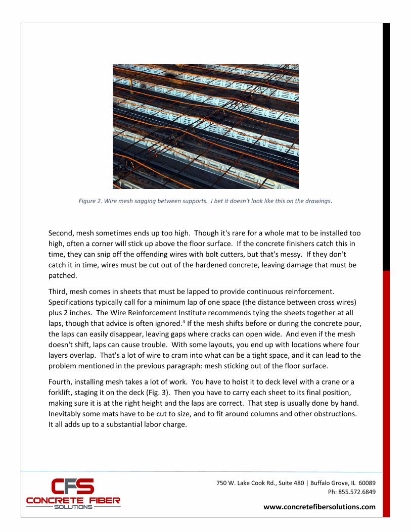
Fourth, installing mesh takes a lot of work. You have to hoist it to deck level with a crane or a
forklift, staging it on the deck (Fig. 3). Then you have to carry each sheet to its final position,
making sure it is at the right height and the laps are correct. That step is usually done by hand.
Inevitably some mats have to be cut to size, and to fit around columns and other obstructions.
It all adds up to a substantial labor charge.
750 W. Lake Cook Rd., Suite 480 | Buffalo Grove, IL 60089
Ph: 855.572.6849
www.concretefibersolutions.com
Figure 3. Wire mesh must be hoisted to deck level and staged there before it is finally set in place. Each step takes time and costs money. In contrast, steel fibers arrive in the concrete truck and are placed along with the concrete,
usually by pump.
Last, mesh causes injuries. Walking on corrugated steel is tricky even when the deck is bare,
and mesh makes it worse. The risk of tripping is always there, and it rises if the mesh is chaired
up, as it should be if you want it to do its job.
STEEL FIBERS -- THE REPLACEMENT FOR WIRE MESH
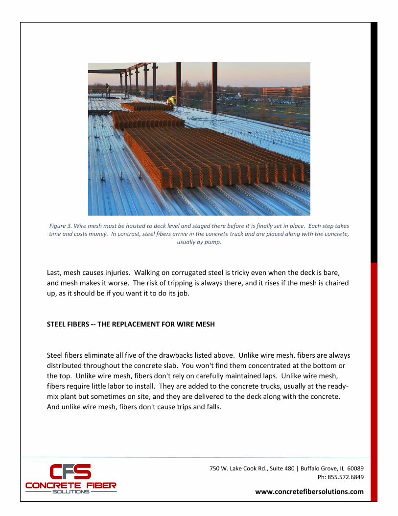
Steel fibers eliminate all five of the drawbacks listed above. Unlike wire mesh, fibers are always
distributed throughout the concrete slab. You won't find them concentrated at the bottom or
the top. Unlike wire mesh, fibers don't rely on carefully maintained laps. Unlike wire mesh,
fibers require little labor to install. They are added to the concrete trucks, usually at the ready-
mix plant but sometimes on site, and they are delivered to the deck along with the concrete.
And unlike wire mesh, fibers don't cause trips and falls.
750 W. Lake Cook Rd., Suite 480 | Buffalo Grove, IL 60089
Ph: 855.572.6849
www.concretefibersolutions.com
Figure 4. This concrete contains steel fibers at 25 pcy. The fibers had no noticeable effect on the concrete placement.
Since 2006, the Steel Deck Institute has endorsed the use of steel fibers for crack control in
composite slabs. The recommended minimum dosage is at least 25 pcy (pounds per cubic
yard).5 As with mesh, some engineers specify more than the code minimum when they want
better-than-usual control over cracks. Some composite slabs have been built with a fiber
dosage of 50 pcy. Dosage rates above 50 pcy are rare but not impossible.
OBJECTIONS TO STEEL FIBERS
Are there reasons not to switch from wire mesh to steel fibers? Two objections to steel fibers
are often raised: that fibers will make the concrete hard to pump, and that fibers will show at
the floor surface. Both objections can be valid, but the right fiber goes a long way toward
overcoming them.
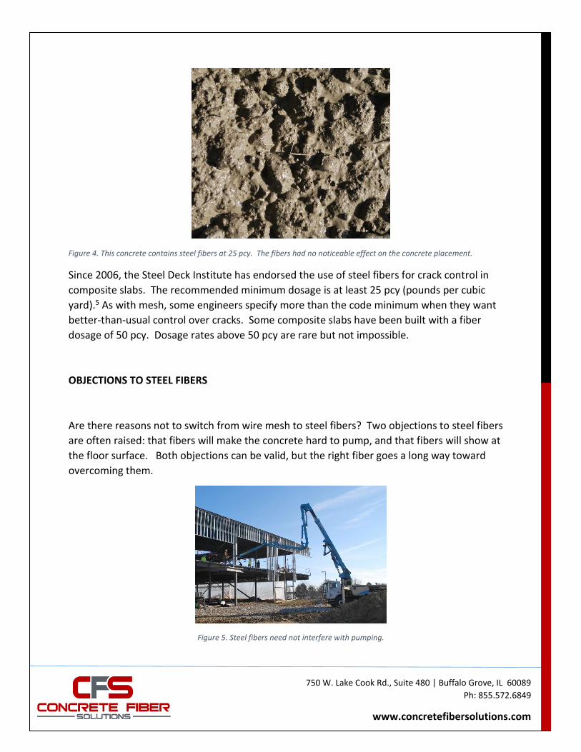
Figure 5. Steel fibers need not interfere with pumping.
750 W. Lake Cook Rd., Suite 480 | Buffalo Grove, IL 60089
Ph: 855.572.6849
www.concretefibersolutions.com
Concrete placed on deck is usually delivered by pumping (Fig. 5), so contractors naturally want
a mix that pumps easily and won't clog. Steel-fiber-reinforced concrete has not always met that
need. But if you look at the jobs where fibers interfered with pumping, almost all involved long
fibers or very high dosages, or both. Few problems arise when you use Type II, 1-inch fibers at
the standard dosage rate of 25 pcy. Such fibers have even been used at 50 pcy with no
noticeable effect on pumpability.
The objection to exposed fibers is a little harder to deal with. As I've said before, if your
tolerance for exposed fibers is literally zero -- that is, not one fiber in sight -- don't use fibers.
But that's an extreme position. With 1-inch fibers and a little care in striking off the concrete,
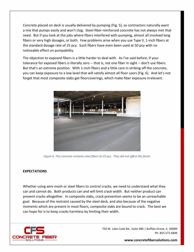
you can keep exposure to a low level that will satisfy almost all floor users (Fig. 6). And let's not
forget that most composite slabs get floorcoverings, which make fiber exposure irrelevant.
Figure 6. This concrete contains steel fibers at 25 pcy. They did not affect the finish.
EXPECTATIONS
Whether using wire mesh or steel fibers to control cracks, we need to understand what they
can and cannot do. Both products can and will limit crack width. But neither product can
prevent cracks altogether. In composite slabs, crack prevention seems to be an unreachable
goal. Because of the restraint caused by the steel deck, and also because of the negative
moments which are present in most floors, composite slabs are bound to crack. The best we
can hope for is to keep cracks harmless by limiting their width.
750 W. Lake Cook Rd., Suite 480 | Buffalo Grove, IL 60089
Ph: 855.572.6849
www.concretefibersolutions.com
This reveals a difference between how steel fibers work in composite and ground-supported
slabs. In ground-supported floors, fibers prevent cracking if you use enough of them. Closely
spaced fibers stop micro cracks from growing into cracks you can see. This is the key to wide-
slab construction with steel fibers, a method that allows slabs up to 125 feet long without
intermediate joints or visible cracks. But that kind of crack prevention works only in slabs that
are free to shrink. Composite slabs are never free because the steel deck restrains them. For
this reason, fibers in composite slabs cannot prevent all cracking; they can only control it.
NEGATIVE-MOMENT CRACKING
The widest cracks in a composite slab usually show up over beams and girders, where negative
moment is present. Steel fibers won't necessarily keep such cracks acceptably tight -- and
neither will wire mesh, for that matter. The Steel Deck Institute says: "The reinforcement
chosen for temperature and shrinkage reinforcement most likely will not supply sufficient area
of reinforcement for negative bending over the supports."6
What do we do about negative-moment cracking, then? The Steel Deck Institute has two
suggestions. One option is to ignore negative moments. Design the floor as if each span were
simply supported (even though it really isn't), and let the cracks open wide over the beams and
girders. According to the Institute, most standard design tables for composite slabs are based
on this notion. The other option is to design for continuity, using the reinforced-concrete
principles set out in ACI 318. This option requires negative reinforcement running
perpendicular to, and centered on, the beams and girders. The negative reinforcement is
usually in bar form, though strips of wire mesh are also possible.
A third solution is sometimes suggested: Saw a joint directly over the beam or girder. Sawn
joints control cracks pretty well in ground-supported slabs, so it hardly seems outrageous to
think they could do the same in composite slabs. However, this approach has not proven
consistently successful. Sometimes a crack appears right next to the joint.
750 W. Lake Cook Rd., Suite 480 | Buffalo Grove, IL 60089
Ph: 855.572.6849
www.concretefibersolutions.com
SWITCHING TO STEEL FIBERS
Converting a composite-slab design from wire mesh to steel fibers is easy.
1. Confirm that the wire mesh is being used to control temperature and shrinkage cracks, not to
provide positive or negative reinforcement.
2. Determine the fiber dosage. If the mesh is the minimum required by the Steel Deck Institute
-- 0.075% of the slab's cross-sectional area or 6x6, W1.4xW1.4, whichever is greater -- replace it
with the minimum fiber dosage: 25 pcy. If the mesh is heavier than the minimum, increase the
fiber dosage in proportion.
3. Specify the fiber type, length, and aspect ratio (or effective diameter, if you prefer). At
Concrete Fiber Solutions, we recommend our CFS100-2 fiber. This is a Type II fiber, 1-inch-long,
with an aspect ratio of 43 (effective diameter 0.023 inch).
4. Don't change the steel deck.
5. If the design includes negative reinforcement, or positive reinforcement that's in addition to
the steel deck, leave it in. Don't try to replace it with fibers.
Now you are ready to enjoy a deck pour without wire mesh.
1. Steel Deck Institute, SDI C-2011, "Standard for Composite Steel Floor Deck-Slabs", 2011, p. 17. 2. Joseph Neuber, "Support Requirements for Welded-Wire Reinforcement in Slabs", Concrete International, September 2006, p. 40. 3. American Society of Concrete Contractors, ASCC Position Statement 2, "Location of Welded-Wire Reinforcement in Concrete Slabs", 2012. 4. Roy H. Reiterman, Technical Consultant to the Wire Reinforcement Institute, "A Sample Specification for Welded Wire Reinforcement", March, 2006. 5. Steel Deck Institute, SDI C-2011, "Standard for Composite Steel Floor Deck-Slabs", 2011, p. 17. 6. Steel Deck Institute, SDI C-2011, "Standard for Composite Steel Floor Deck-Slabs", 2011, p. 15.


![CSSBI-Steel Roof Deck Floor Deck[1]](https://img.dokumen.tips/doc/110x75/552e8098550346231a8b49af/cssbi-steel-roof-deck-floor-deck1.jpg)


