Embed Size (px)
Citation preview

STEEL BUILDINGS IN EUROPE
Multi-Storey Steel Buildings
Part 2: Concept Design
.


Multi-Storey Steel Buildings
Part 2: Concept Design

2 - ii

Part 2: Concept Design
2 - iii
FOREWORD
This publication is a second part of a design guide, Multi-Storey Steel Buildings.
The 10 parts in the Multi-Storey Steel Buildings guide are:
Part 1: Architect’s guide Part 2: Concept design Part 3: Actions Part 4: Detailed design Part 5: Joint design Part 6: Fire Engineering Part 7: Model construction specification Part 8: Design software – section capacity Part 9: Design software – simple connections Part 10: Software specification for composite beams.
Multi-Storey Steel Buildings is one of two design guides. The second design guide is Single-Storey Steel Buildings.
The two design guides have been produced in the framework of the European project “Facilitating the market development for sections in industrial halls and low rise buildings (SECHALO) RFS2-CT-2008-0030”.
The design guides have been prepared under the direction of Arcelor Mittal, Peiner Träger and Corus. The technical conten t has been prepared by CTICM and SCI, collaborating as the Steel Alliance.

Part 2: Concept Design
2 - iv

Part 2: Concept Design
2 - v
Contents
Page No
FOREWORD iii SUMMARY vi 1 INTRODUCTION: STRUCTURAL DESIGN IN OVERALL BUILDING DESIGN 1
1.1 Hierarchy of design decisions 2 1.2 Client requirements 3 1.3 Economics 5 1.4 Construction programme 6 1.5 Sustainability 7
2 BENEFITS OF STEEL CONSTRUCTION 11 2.1 Speed of construction 11 2.2 Construction process 12 2.3 Long spans and service integration 13 2.4 Lightweight structures and resource efficiency 14 2.5 Benefits of adaptability 15
3 CASE STUDIES ON MULTI-STOREY STEEL BUILDINGS 16 3.1 Office Building, Bishops Square, London 16 3.2 Le Seguana, Paris 18 3.3 Luxembourg Chamber of Commerce 19 3.4 Kings Place, Kings Cross, London 20 3.5 Kone Headquarters, Helsinki 21 3.6 AM Steel Centre, Liege 22
4 ANATOMY OF BUILDING DESIGN 24 4.1 Floor grids 24 4.2 Dimensional coordination 25 4.3 Structural options for stability 27 4.4 Columns 30 4.5 Structural options for floor systems 31 4.6 Factors influencing structural arrangements 35 4.7 Structure – service integration 37
5 FLOOR SYSTEMS 40 5.1 Composite construction 40 5.2 Composite beams and composite slabs with steel decking 40 5.3 Long-span composite beams with web openings 45 5.4 Cellular composite beams with composite slab and steel decking 47 5.5 Composite beams with precast concrete units 50 5.6 Non-composite beams with precast units 53 5.7 Integrated beams with precast concrete units 55 5.8 Asymmetric beams and deep decking 59 5.9 Beam connections 60
6 OTHER DESIGN ISSUES 63 6.1 Accidental Actions 63 6.2 Floor dynamics 65 6.3 Corrosion protection 67 6.4 Temperature effects 67 6.5 Fire safety 67 6.6 Acoustic performance 68 6.7 Energy efficiency 70 6.8 Cladding 70
REFERENCES 75

Part 2: Concept Design
2 - vi
SUMMARY
This publication p resents information necessary to assist in the choice and use of steel structures a t the concep t design sta ge of modern m ulti-storey build ings. The primary sector of interest is commercial buildings, but the same information may also be used in other sectors. The inform ation is presented in terms of the design strategy, anatom y of building de sign and stru ctural syste ms that are relev ant to the m ulti-storey build ings. This publication on the concept design of m ulti-storey frames complements other parts of the guide.
The use of long span composite construction is considered to be a very im portant step towards th e grea ter u se of stee l in m ulti-storey buildin gs, and th ese f orms of construction are em phasised in this publicat ion. Cellular b eams and perforated s teel sections are prom oted, as integrated solu tions providing long spans without increasing overall floor depth. Long spans provide co lumn-free adaptable space with fewer foundations. Integrated beam s are also benefi cial where the beam depth is m inimised, such as in renovation applica tions. Other form s of floor c onstruction, such as precast concrete units, are also covered.
Tables are provided for prelim inary design of the variou s structu ral system s, with typical layouts, sizes and guidance on the key design issues.

Part 2: Concept Design
2 - 1
1 INTRODUCTION: STRUCTURAL DESIGN IN OVERALL BUILDING DESIGN
In m ulti-storey buildin gs, the des ign of the prim ary structure is s trongly influenced by many issues, as defined below:
The need to provide clear floor spans for more usable space
The choice of cladding system
Planning requirem ents, which m ay limit the building h eight and the maximum floor-to-floor zone
The services strategy and effective integration of building services
Site conditions, which dictate the foundation system and location of foundations
Craneage limitations and storage space for materials and components
Speed of construction, which may influence the number of components that are used and the installation process.
Studies show that the cost of the building structure is generally only 10% of the total building cost – and the influen ce of the choice of structure on the foundations, services and claddi ng are often more significant [1]. In reality , building design is a synthesis of architect ural, structural, services, logistics and buildability issues. Stee l f rames ar e ide ally su ited f or m odern m ulti-storey commercial buildings such as that shown in Figure 1.1.
Figure 1.1 Modern commercial building in steel

Part 2: Concept Design
2 - 2
1.1 Hierarchy of design decisions The development of any proposal for a construction project requires a complex series of design decisions that are inte r-related. The process should begin with a clear und erstanding of the clien t re quirements and of local conditions or regulations. Despite th e com plexity, it is possible to identify a hierarchy of design decisions, as shown in Figure 1.2.
Firstly, planning requirem ents are likely to define the overall building for m, which will also in clude aspects such as natural light, ventil ation and services. The principal design ch oices that n eed to be made in close consultation with the client are:
The depth of the floor zone and the overall s tructure/service inte raction strategy
The need for special structural arrange ments in public spaces or circulation areas
The provision of som e tolerance between structure and serv ices, to perm it future adaptability
The benefit of using longer span structure, at negligible extra cost, in order to enhance flexibility of layout.
Based on the design brief, a concept design is then prepared and is reviewed by the design team and client. It is this early inte ractive stage where the important decisions are made that influence th e cost and value of the final pro ject. Close involvement with the client is essential.
Figure 1.2 Hierarchy of design decisions

Part 2: Concept Design
2 - 3
Once the co ncept design is agreed, the detailed design of the building and its components is usually undertaken with le ss direct interaction with the client. Connections and interfaces between the com ponents are often detailed by the fabricator or specialist designer but the lead architect should have an understanding of the form of these details.
1.2 Client requirements 1.2.1 Spatial Requirements
Client requirements may be defined firs tly by general physica l aspects of the building, e.g. the num ber of occupants a nd their range of functions, planning modules or floor-to-floor zones. Minim um floor loadings a nd fire resistance periods are defined in national regulations , but the client m ay wish to specify higher requirements.
Examples of general client requirements are:
Occupation density 1 person per 10 m to 15 m2
Useable floor area : Total area 80 to 90% typically
Floor-to-floor zone 3,6 m to 4,2 m
Floor-to-ceiling zone 2,7 m to 3 m typically
Planning module 1,2 m to 1,5 m
Imposed loading 2,5 to 7,5 kN/m2
Fire resistance R60 to R120
The floor-to-floor zone is a key param eter, which is influenced by planning requirements on overall building height, natural light, claddi ng cost and other aspects.
1.2.2 Service requirement
Other client requirem ents m ay be defi ned under the heading of ‘servicing’, which includes Inform ation Technology and other comm unication issues in addition to ventilation, lighting and other servicing requirements. In most inner city projects , air cond itioning or co mfort cooling is essen tial, becaus e nois e limits the u se of natura l ventila tion. In sub-urban or m ore rural sites, natural ventilation may be preferred.
Design req uirements f or building serv ices are usu ally dete rmined by regulations in the country where th e structure is to be constructed and are a function of the external and internal environments.
Typical examples of client requirem ents for design of the prim ary building services are:
Fresh air supply 8-12 litres/sec per person
Internal temperatures 22C 2C
Cooling load 40-70 W/m2
Thermal insulation (walls) U < 0,35 W/m2K

Part 2: Concept Design
2 - 4
Data communications are norm ally placed un der a rais ed access floor to facilitate access by th e user and futu re m odifications. O ther services are generally supported under the floor, above a ceiling. The services can becom e highly congested and an integrated solu tion, such as that shown in Figure 1.3 can be advantageous in m inimising the overall depth required to accommodate both structure and services.
Figure 1.3 Services integrated with a cellular floor beam
1.2.3 Floor loading
Floor loadings are presented in nati onal Regulations or in EN 1991-1-1, and minimum values can b e increased by c lient requirem ents. Floor loading has three basic components:
Imposed loading, including partitions
Ceiling and services, and a raised floor
Self weight of the structure.
Imposed loading is dependant on the use of the building and design loads range from 2,0 to 7,5 kN/m2, as illustrated in Table 1.1, which has been extracted from Table 6.2 of EN 1991-1-1. Imposed loads on floors shoul d be taken from EN 1991-1-1 Tables 6.1 and 6.2. §6.3.1.2( 8) provides an allowance for movable partitions ranging between 0,5 kN/m2 and 1,2 kN/m2. A further 0,7 kN/m2 is generally allowed for ceiling, services and a raised floor.
For perimeter beams, it is necess ary to includ e the load ing from façade walls and internal finishes w hich can range f rom 3 to 5 kN/m f or ligh tweight cladding to 8 to 10 kN/m for brickwork and 10 to 15 kN/m for precast concrete panels.
The self weight of a typical co mposite floor is 2,8 to 3,5 kN/m2, which is only about 50 % of that of a 200 mm deep rein forced concrete flat slab. The self weight of a precast hollow core concrete slab and concrete topping is ty pically 3,5 to 6,5 kNm2 for a similar span.

Part 2: Concept Design
2 - 5
Other typical weights are illustrated in Table 1.2.
Table 1.1 Typical imposed loads for offices (kN/m2)
En 1991-1-1 Category
Application Imposed Loading
Partitions Ceiling,
Services, etc.
B Offices - general 2,0 – 3,0 0,5 – 1,2 0,7
C1 Areas with tables 2,0 – 3,0 0,5 – 1,2 0,7
C2 Areas with fixed seats 3,0 – 4,0 0,5 – 1,2 0,7
C3 Areas open to crowds 3,0 – 5,0
C5 Areas open to large crowds
5,0 – 7,5
Table 1.2 Typical weights for building elements
Element Typical weight
Precast units (Spanning 6 m, designed for a 5 kN/m2 imposed load) 3,5 to 4,5 kN/m2
Composite slab (Normal weight concrete, 140 mm thick) 2,8 to 3,5 kN/m2
Composite slab (Light weight concrete, 130 mm thick) 2,1 to 2,5 kN/m2
Services (lighting) 0,25 kN/m2
Ceilings 0,1 kN/m2
Steelwork (low rise 2 to 6 storeys) 35 to 50 kg/m2
Steelwork (medium rise 7 to 12 storeys) 40 to 70 kg/m2
1.2.4 External Loading
Roofs are subject to imposed loads, to be taken from EN1991-1-1, typically 0,4 or 0,6 kN/m2.
Roofs are also subject to snow load s, which should be determ ined from EN 1991-1-3.
Wind loads should be calculated from EN 1991-1-4.
The determination of these loads is covered by other documents in this series[2].
1.3 Economics 1.3.1 Cost of construction
A breakdown of construction cost s for a typical office building [1] is approximately as below:
Foundations 5-15%
Super structure and floors 10-15%
Cladding and roofing 15-25%
Services (mechanical and electrical) 15-25%
Services (sanitation and other services) 5-10%
Finishes, partitioning and fitments 10-20%
Preliminaries (site management) 10-15%

Part 2: Concept Design
2 - 6
Preliminaries represent the costs of the site management and control facilities, including cranes, storag e and equip ment. Site preliminaries can vary with the scale of the project and a figure of 15% of the tota l cost is of ten allowed for steel in tensive cons truction reduc ing to 12% for higher levels of offsite prefabrication. The superstructure or fra mework cost is rarely m ore than 10% of the to tal, but it has an im portant effect on other costs. For ex ample, a reduction of 100 mm in the ceiling floor zone can lead to a 2,5% saving in cladding cost (equivalent to 0,5% saving in overall building cost).
1.3.2 Benefits of steel construction
Steel construction offers m any benefits to the client/user in o peration including:
Column-free spans, permitting flexibility in use
Ease of extension and adaptation in the future, including needs for re-servicing
Variety of cladding and roofing systems
Long design life and ease of maintenance
Energy efficient design.
These benefits of steel construction are explored in Section 2.
1.3.3 Cost of ownership / occupancy
It is estimated that the total cost of running a building during a 60 year design life may be 3 to 5 times the cost of initial construction. Major com ponents in the longer term costs include:
Direct running costs of heat, lighting, air conditioning
Refurbishing the interior, m inor redecoration every 3-5 years, m ajor refitting every 10-20 years
Replacing the services, approximately every 15-20 years
Possibly re-cladding the building after 25-30 years.
The European Directiv e on Energ y Sa ving in Buildings now requires that office buildings carry an ‘energy pass port’ which defines the energy use and energy saving m easures. Many modern buildings are designed with energy saving measures in m ind, including double skin facades, therm al capacity and chimneys for natural ventilation and photovoltaics in roofing.
1.4 Construction programme A typical construction programme for a medium-sized office building is shown in Figure 1.4. One of the advantages of steel construction is that the initial period of site preparation and foundati on construction permits sufficient tim e for off-site fabrication of the steel structure into a ‘kit of parts’. This is known as ‘Fast track’ construction.
Part 2: Concept Design
2 - 7
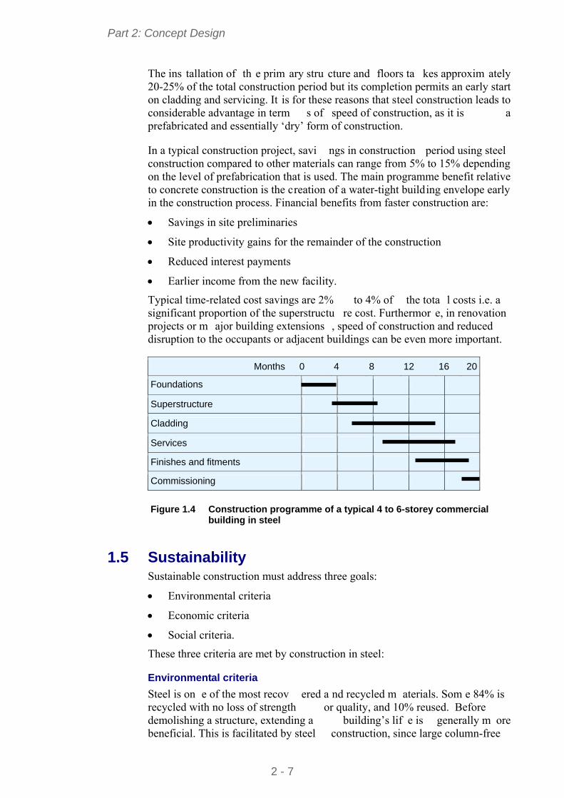
The ins tallation of th e prim ary stru cture and floors ta kes approxim ately 20-25% of the total construction period but its completion permits an early start on cladding and servicing. It is for these reasons that steel construction leads to considerable advantage in term s of speed of construction, as it is a prefabricated and essentially ‘dry’ form of construction.
In a typical construction project, savi ngs in construction period using steel construction compared to other materials can range from 5% to 15% depending on the level of prefabrication that is used. The main programme benefit relative to concrete construction is the creation of a water-tight building envelope early in the construction process. Financial benefits from faster construction are:
Savings in site preliminaries
Site productivity gains for the remainder of the construction
Reduced interest payments
Earlier income from the new facility.
Typical time-related cost savings are 2% to 4% of the tota l costs i.e. a significant proportion of the superstructu re cost. Furthermor e, in renovation projects or m ajor building extensions , speed of construction and reduced disruption to the occupants or adjacent buildings can be even more important.
Months 0 4 8 12 16 20
Foundations
Superstructure
Cladding
Services
Finishes and fitments
Commissioning
Figure 1.4 Construction programme of a typical 4 to 6-storey commercial
building in steel
1.5 Sustainability Sustainable construction must address three goals:
Environmental criteria
Economic criteria
Social criteria.
These three criteria are met by construction in steel:
Environmental criteria
Steel is on e of the most recov ered a nd recycled m aterials. Som e 84% is recycled with no loss of strength or quality, and 10% reused. Before demolishing a structure, extending a building’s lif e is generally m ore beneficial. This is facilitated by steel construction, since large column-free

Part 2: Concept Design
2 - 8
spaces give flexibility for change in use. Advances in the manufacturing of raw materials means that less water and en ergy is used in production, and allows for significant reductions in noise, particle and CO2 emissions. Economic criteria
Steel construction brings together the va rious elem ents of a structure in an integrated design. The m aterials are m anufactured, fabricated and constructed using efficient production processes. Th e use of m aterial is highly optim ised and waste virtu ally elim inated. The stru ctures them selves are used f or all aspects of m odern life, including logistics, retail, comm ercial, and manufacturing, providing th e infrastructure on whic h society depends. Steel construction provides low investment costs, optim um ope rational costs and outstanding flexibility of building us e, with high quality, functionality, aesthetics and fast construction times. Social criteria
The high proportion of offsite fabrication in steel buildings means that working conditions are safer, controlled and protected from the weather. A fixed location for employees helps to develop communities, family life and the skills. Steel releases no harm ful substances into the environm ent, and steel buildings provide a robust, safe solution.
Multi-storey buildings
The design of m ulti-storey building s is in creasingly depend ent on asp ects of sustainability, defined by criteria such as:
Efficient use of materials and responsible sourcing of materials
Elimination of waste in manufacturing and in construction processes
Energy efficiency in building operation, including improved air-tightness
Measures to reduce water consumption
Improvement in indoor comfort
Overall management and planning criteria, such as public transport connections, aesthetics or preservation of ecological value.
Steel framed buildings can be designed to satisfy all these criteria. Some of the recognised sustainability benefits of steel are:
Steel structures are ro bust, with a long life. Properly detailed and maintained, steel structures can be used indefinitely
Approximately 10% of steel sections are re-used[3]
95% of structural steel sections are recycled
Steel p roducts can po tentially b e di smantled and reused, particularly modular components or steel frames
Steel structures are lightweight for use on poor ground or over tunnels
Steel is manufactured efficiently in factory controlled processes
All waste is recycled in manufacture and no steel waste is produced on site

Part 2: Concept Design
2 - 9
Construction in steel m aximises th e opportunity and ease of extending buildings and change of use
High levels of thermal insulation can be provided in the building envelope
Prefabricated construction systems are rapidly installed and are much safer in terms of the construction processes
Steel construction is safe to install, and safety features can be introduced into the steel design, such as pre-attached safety barriers, as shown in Figure 1.5.
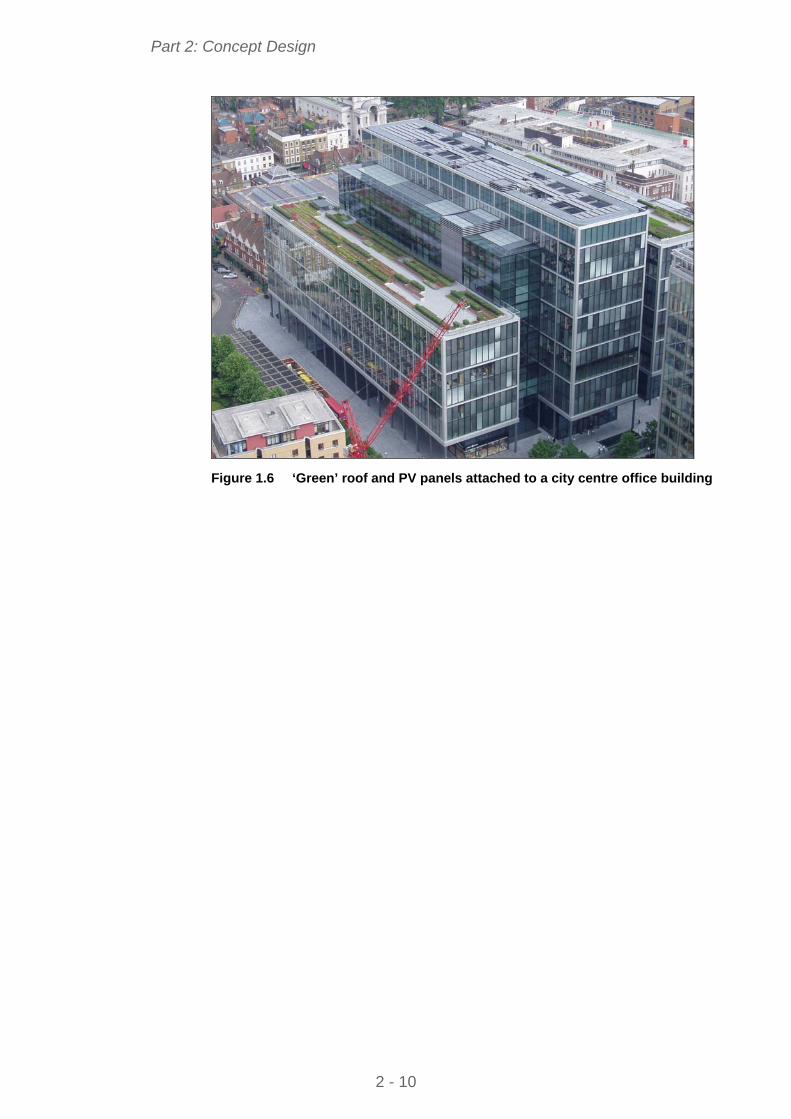
Different sustain ability assessm ent m easures exist in various European countries[4]. National building regulations pr esent m inimum levels of overall energy performance which m ust be satis fied. Many m ulti-storey buildings are designed with solar shading and active energy creation technologies, such as Photovoltaics (PVs), as shown in Figure 1.6.
Utilisation of the ther mal capacity of the building s tructure can be achieved using composite slabs, and research has shown that a slab depth of only 50 mm to 75 mm is needed to provide adequate fabric energy storage[5].
Figure 1.5 Safety barriers pre-attached to the perimeter steelwork
Part 2: Concept Design
2 - 10
Figure 1.6 ‘Green’ roof and PV panels attached to a city centre office building

Part 2: Concept Design
2 - 11
2 BENEFITS OF STEEL CONSTRUCTION
In the multi-storey building sector, the benefits of steel construction are largely related to th e ‘fast track’ nature of the construction process, which leads to a wide range of financial and process benefits. Many innovations associated with the construction process have further im proved these inherent benefits and have increased efficiency and productivity. This is very important in inner city projects wh ere lack of space for storag e of m aterials and other facilities, limitations on delive ries and logistics, a nd planning constraint s, m ean that a higher proportion of work should be done in the factory and less on site.
The benef its of stee l in m ulti-storey cons truction arise m ainly f rom its prefabricated nature, its lightweight and the ability to phase the vario us activities in series rath er than in pa rallel. These benef its ar e explored in the following sections.
2.1 Speed of construction Speed of construc tion is the m ost important benefit offered by steel construction, which le ads to f inancial, m anagement and other logistical benefits, many of which can be e xperienced in econom ic as we ll as sustainability terms. For an eight-storey office building, it is found that steel construction is up to 20% faster than re inforced concrete, but, im portantly, the construction of the primary frame and floors is up to 40% faster and allows for early start in build ing services, installation, cladding and ot her activities. The fast construction process is based on a synergistic us e of steel fram es, steel decking and in som e cases, concrete or braced steel cores, as illustrated in Figure 2.1.
The financial benefits of speed of construction may be expressed as:
Early completion, which leads to reduced interest charges on the borrowed capital and to early return in terms of revenue
Lower cash flow
Reduced m anagement costs on-site , due prim arily to the sho rter construction period, but also due to the fewer personnel employed
Reduced hire costs of site facilities
Greater certainty and less risk in the construction process.

Part 2: Concept Design
2 - 12
Figure 2.1 Rapid installation of steelwork and steel decking speeds up the
construction process
2.2 Construction process Speed of construction is achieved by ‘j ust in time’ delivery of components and by rapid assem bly for the steel fram ework. It is estim ated that a sing le tower crane can install up to 20 steel elements per day, which corresponds to a floor area of approximately 300 m2.
Secondary benefits in steel construction arise from:
Placing of steel decking, in ‘bundles ’ on the beam s and installation of decking at a rate of up to 500 m2 per day
Avoidance of tem porary propping by usi ng steel decking spans of 3 m to 4 m for profiles of 50 mm to 80 mm depth
Fire pro tection by intu mescent coating th at is applied in the factory and, therefore, eliminates the time required for this process on-site
Opportunities for reduction in the amount of fir e protection by use of fire engineering analysis
Use of mobile installation platforms improve construction safety and speed up the installation process, as shown in Figure 2.2
Prefabricated stairs that are installe d as part of the steel construction package
Safety barriers can be attached to the perimeter steel beams, see Figure 1.5
Rapid concrete placem ent of up to 1000 m2 area in one day for a 130 m deep slab

Part 2: Concept Design
2 - 13
Light s teel inf ill walls a nd partitions that a re installed rapid ly and can be prefabricated
Modular serviced units that may be installed with the steelwork package.
Figure 2.2 Rapid, safe installation of steelwork and steel decking from a mobile erection platform speeds up the construction process
2.3 Long spans and service integration The integration of building services within the prim ary structure can be achieved by two methods:
Designing the structure to be of m inimum construction depth so that services pass beneath
Designing the structure with periodic openings or zones for integration of services within the structural depth.
Long span construction is attractive because it eliminates the need for in ternal columns and makes the internal space more adaptable to a range of current and future uses. Spans of 12 m to 18 m are readily achiev ed by a variety of structural steel technologies.
The minimum structural depth is achieve d by use of slim floor or integrated beams whic h have a m aximum s pan capability of around 9 m. Structura l systems which provide for service integration include:
Cellular beams with regular circular openings, as shown in Figure 1.3
Rolled or f abricated steel beams with periodic openings, often rectangular in shape, as shown in Figure 2.3
Trusses or other open shaped members.

Part 2: Concept Design
2 - 14
For comm ercial buildings, the floor a nd service zone is typically 800 mm to 1200 mm. For renovation projects where the original façade is retained, sli m floor or integrated beam s have proved to be attractive a nd can achieve an overall floor zone of less than 600 mm.
The economics of long span construction may be summarised as:
Saving in cladding cost (up to 300 mm per floor)
Elimination of internal c olumns and incre ase in useable a rea (up to 3% of the plan area)
Fewer steel elements to install (up to 25% less)
Columns and façades can be located at the perimeter of the building
Ease of service integration and future servicing
Future adaptability of the space and re-use of the building.
Figure 2.3 Rectangular openings in composite beams for service distribution
2.4 Lightweight structures and resource efficiency Steel construction of all t ypes is lightweight, even when including concrete floors. The self weight of a typical co mposite floor system is typically only 40% of that of a reinforced concrete flat slab. When the total building weight is considered, a steel framed structure is up to 30% lighter than the equivalent concrete building, which leads to an equivalent saving in foundation costs.

Part 2: Concept Design
2 - 15
Furthermore, steel construction is the preferred solution for building on:
Post-industrial or former built-on sites, often with pre-existing foundations
Building over underground services and tunnels
Building on railway lines and other ‘podium-type’ structures.
Steel construction virtually eliminates waste by the nature of its m anufacturing process an d all s teel waste is recycled. S ynergistic m aterials s uch as plasterboard can also be recycled.
2.5 Benefits of adaptability General expectations for all multi-storey buildings change substantially during their design lives. A building’s occupancy is also likely to change several times during its life. Increasingly, the nature of the occupancy m ay change; for example in m any m ajor European cities , there is a growing trend to convert office buildings into apartments.
In the 1960s and 70s, m any buildings we re constructed to m inimum cost without any allowance f or future adapta tion. These structures have not proved capable of responding to occupant’s cha nging needs, leading to their early demolition.
Although difficult to quantify at the proposal development stage, there are clear qualitative benefits in specifying a stru cture that is inh erently adaptable to changes in requirements during its design life. Key issues on adaptability are:
Specifying longer spans, permitting greater flexibility of layout
Providing space for additional services
Specifying floor loadings that permit change of occupancy.

Part 2: Concept Design
2 - 16
3 CASE STUDIES ON MULTI-STOREY STEEL BUILDINGS
The following case studies describe the us e of steel in m ulti-storey buildings, primarily in the comm ercial building sector, but a lso in the residential sector, where the same technologies are used.
3.1 Office Building, Bishops Square, London
Figure 3.1 Office building, Bishop’s Square, London
The Bishop's Square project near to London's Broadgate area com prises a composite steel structure of 18 m s pan and only 650 mm depth. There is an almost fully glazed façade and a 'green' roof space on three levels . The completed building is shown in Fi gure 3.1, and during construction in Figure 3.2.
The 12-storey building of close to 80000 m2 floor area comprised approximately 9500 tonnes of steelwork, and was erected in only 30 weeks out of an overall 20 month construction programme. Fire protection, in the form of intumescent coatings, was applied o ff-site in a si ngle operation by the steelwork contractor, which speeded up the following trades.
The highly glazed façade was designed to satisfy onerous thermal requirements which led to the use of triple glazing w ith integral louvres. Photovoltaic panels were installed on the roof to provide an energy source for lighting, thereby reducing running costs and CO2 emissions.

Part 2: Concept Design
2 - 17
The floor-to-floor height was only 3,9 m, which necessitated a beam depth of only 650 mm as part of a 1050 mm overall floor zone. The 9 m span heavily loaded primary beam s had larg e recta ngular openings, and were tapered in depth close to the concrete cores to allow for distribution of large ducts.
Secondary beam s were designed as fabricat ed steel sections with a series of 425 mm diameter circular openings for services and two rectangular openings of 425 mm depth × 750 mm length close to m id-span. An im posed load deflection limit of only 30 mm was specified, which was achieved by beams of 138 kg/m weight with no stiffening.
Figure 3.2 View of long span cellular beams in the Bishop’s Square project

Part 2: Concept Design
2 - 18
3.2 Le Seguana, Paris Le Seguana is a 25000 m2 office developm ent on the banks of the Seine in Paris, shown in Figure 3.3. It consists of colu mn free spaces of 18 m 36 m and is fully air conditioned. The constr uction was completed in 22 months to programme and budget, including the er ection of 2000 tonnes of structural steelwork in only 12 weeks.
Figure 3.3 Le Seguana buildings, Paris, during construction
Stability for the structure was provided by a combination o f steel braced cores and slip-formed concrete cores.
The strategy for air conditioning involved local control for every 12 m2 of floor space. This dem anded a larg e number of ducts , which were accomm odated within the cellular beams, as illustrated in Figure 3.4.
Figure 3.4 Ducts emanating from central plant room – providing locally
controlled environment
Part 2: Concept Design
2 - 19
3.3 Luxembourg Chamber of Commerce
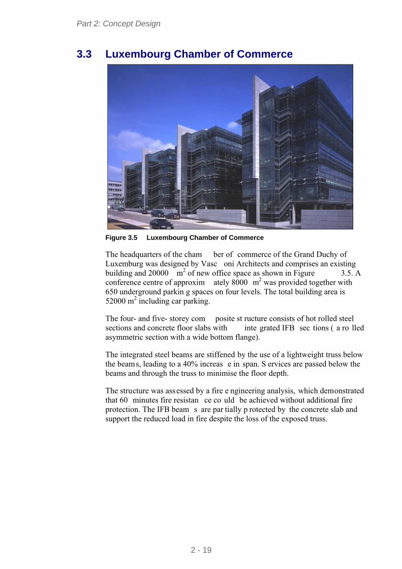
Figure 3.5 Luxembourg Chamber of Commerce
The headquarters of the cham ber of commerce of the Grand Duchy of Luxemburg was designed by Vasc oni Architects and comprises an existing building and 20000 m2 of new office space as shown in Figure 3.5. A conference centre of approxim ately 8000 m2 was provided together with 650 underground parkin g spaces on four levels. The total building area is 52000 m2 including car parking.
The four- and five- storey com posite st ructure consists of hot rolled steel sections and concrete floor slabs with inte grated IFB sec tions ( a ro lled asymmetric section with a wide bottom flange).
The integrated steel beams are stiffened by the use of a lightweight truss below the beams, leading to a 40% increas e in span. S ervices are passed below the beams and through the truss to minimise the floor depth.
The structure was assessed by a fire e ngineering analysis, which demonstrated that 60 minutes fire resistan ce co uld be achieved without additional fire protection. The IFB beam s are par tially p rotected by the concrete slab and support the reduced load in fire despite the loss of the exposed truss.
Part 2: Concept Design
2 - 20
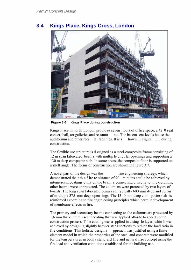
3.4 Kings Place, Kings Cross, London
Figure 3.6 Kings Place during construction
Kings Place in north London provid es seven floors of office space, a 42 0 seat concert hall, art galleries and restaura nts. The basem ent levels house the auditorium and other reci tal facilities. It is s hown in Figure 3.6 during construction.
The flexible use structure is d esigned as a steel-composite frame consisting of 12 m span fabricated beams with multip le circular openings and supporting a 130 m deep composite slab. In some areas, the composite floor is supported on a shelf angle. The forms of construction are shown in Figure 3.7.
A novel part of the design was the fire engineering strategy, which demonstrated tha t th e f ire re sistance of 90 minutes coul d be achieved by intumescent coatings o nly on the beam s connecting d irectly to th e c olumns; other beams were unprotected. The colum ns were protected by two layers of boards. The long span fabricated beam s are typically 600 mm deep and consist of m ultiple 375 mm deep open ings. The 13 0 mm deep com posite slab is reinforced according to fire engin eering principles which perm it development of membrane effects in fire.
The primary and secondary beams connecting to the co lumns are p rotected by 1,6 mm thick intum escent coating that was applied off-site to speed up the construction process. T he coating was a pplied in a sing le layer, whic h was achieved by designing slightly heavier stee l sections to reduce the load ratio in fire conditions. This holistic design a pproach was justified using a finite element model in which the properties of the steel and concrete were modified for the tem peratures in both a stand ard fire and nat ural fi re concept using the fire load and ventilation conditions established for the building use.

Part 2: Concept Design
2 - 21
Figure 3.7 Different beam types used in Kings Place
3.5 Kone Headquarters, Helsinki
Figure 3.8 Kone building during construction and completed
The 18-storey Kone headquarters build ing in Espoo near Helsinki used a composite fl oor structure and had a fully glazed façade. The total floo r area was 9800 m2. Stability was provide d by a large concrete co re loca ted on the south face of the building, as shown in Figure 3.8.
The structure was innovative in its construction because the floor structure was prefabricated as large cassettes and lifte d into place, as shown in Figure 3.9. The span of the floor grid was 12,1 m for the primary beams and 8,1 m for the secondary beams. A minimum number of steel columns were used internally.
The east and west facing walls have full height glass panels. The cladding was configured as a double facade to pro vide shading and also to act as a th ermal barrier. The concrete core next to the south facing wall reduced the heat gain on this façade.

Part 2: Concept Design
2 - 22
Figure 3.9 Prefabricated floor cassette system
3.6 AM Steel Centre, Liege
Figure 3.10 AM building during construction showing the cellular beams

Part 2: Concept Design
2 - 23
The five-storey Steel Centre in Liege, Belgium is an innovative office building designed to achieve a high level of energy efficiency. It is 16 m 80 m on plan and consists of an off-centre line of in ternal columns to create beam spans of 9 m and 7 m. The longer span seconda ry members are 500 mm deep and are placed at 3 m spacing, which support a composite floor. The secondary members use IPE330/ IPE 300 sections to create cellular b eams with regular 400 mm diameter openings. The form of construction is shown in Figure 3.10. The 9 m span prim ary cellular beam s are the sam e depth and use HEB 320/ HEA 320 sections.
A fire engin eering analysis was carried out to d emonstrate that th e composite beams coul d be unprotected except for those connected to the colum ns. The columns are concrete filled circular hollow sections, which are unprotected and achieve the required fire resistance, lead ing to a considerable reduction in fire protection costs.
The build ing is suppo rted on piles because of the poor gro und conditions in this former industrial area. The low se lf weight of the structure (< 350 kg/m2) and of the curtain walling system was important in minimising the loads on the piles.
Part 2: Concept Design
2 - 24
4 ANATOMY OF BUILDING DESIGN
The building design is dependent on various parameters:
Floor grid
Building height
Circulation and access space
Services requirements and service integration.
These aspects are addressed as follows:
4.1 Floor grids Floor grids define the spacing of the columns in orthogonal directions, which are influenced by:
The planning grid (norm ally based on units of 300 mm but m ore typically multiples of 0,6, 1,2 or 1,5 m)
The colum n spacing along the façade, depend ing on th e façade m aterial (typically 5,4 m to 7,5 m)
The use of the internal space (i.e. for offices or open plan space)
The requirements for building service distribution (from the building core).
Along the façade lin e, colum n spa cings are no rmally defined by the need to provide support to the cl adding system (for exam ple, a m aximum column spacing of 6 m is normally required for brickwork). This influences the column spacing internally, unless additional columns are used along the façade line.
The span of the beam s across the building norm ally conform s to one of the following column grid arrangement:
Single internal line of colum ns, placed offset to the line of a central corridor. This is shown in Figure 4.1
Pairs of column lines on either side of a corridor
Column-free internal spans with columns located along the façade line.
For naturally ventilated offices, a build ing width of 12 m to 15 m is typically used, which can be achieved by two spans of 6 m to 7,5 m. A single span can also be pro vided with deep (400 mm or m ore) precast concrete hollow core units spanning the full width of the build ing. Natural lighting also plays a role in choice of the width of floor plate.
However, in m odern buildings, a long sp an solution provides a cons iderable enhancement in flexibility of layout. For air-conditioned offices, a clear span of 15 m to 18 m is often used. An exam ple of the colum n grid for a long span option in a building with a large atrium is shown in Figure 4.2.

Part 2: Concept Design
2 - 25
7.5 m
6 m
6 m
48 m
13.5 m
T
L L
T
LS S
L – Lift; S – Stairs; T – Toilets Figure 4.1 Column grid for a naturally ventilated office
7.5 m7.5 m
7.5 m
7.5 m
15 m
15 m
30 m15 m
60 m
45 m
L
T
L
L
L
L
T
S S
L
S
L – Lift; S – Stairs; T – Toilets Figure 4.2 Column grid for long span floor in a prestige air conditioned office
4.2 Dimensional coordination The choice of the basic building shape is usually the Architect’s responsibility, constrained by such issues as th e site plan, access, building orien tation, parking, landscaping and local planni ng requirem ents. The following general guidance influences the choice of structure.
Between sources of natural light there should be 13,5 m and 20 m intervals
Naturally lit and ventilated zone s extend a distan ce of twice the floor-to-ceiling height from the outer wa lls – artificial li ght and ventilation is required in other zones

Part 2: Concept Design
2 - 26
Atria improve the efficient use of the building, and reduce the running costs.
4.2.1 Influence of building height
The building height has a strong influence on the:
Structural system that is adopted
Foundation system
Fire resistance requirements and means of escape
Access (by lifts) and circulation space
Choice of cladding system
Speed of construction and site productivity.
For taller b uildings, s trategically p laced concrete o r b raced steel cores ar e usually adopted. Ultra tall build ings are influen ced strongly by th e stabilising system, but are outside the scope of this guidance.
Sizes of lifts and their speed of movement also becom e important considerations for tall buildings.
Depending on the Regulations for fi re safety in the particular country, the use of sprinklers m ay be required for buildi ngs of more than eight storeys (or approximately 30 m high).
4.2.2 Horizontal coordination
Horizontal coordination is dominated by the need on plan for defined zones for vertical access, safe evacuation in fi re, and vertical se rvice distribution. Positioning of service and access cores is influenced by:
Horizontal distribution systems for mechanical services
Fire r esistance requ irements, which may control evacuation routes and compartment sizes
The need to distribute the stabilizing systems (bracing and cores) effectively throughout the building plan.
Figure 4.1 and Figure 4.2 show typical arrangements that satisfy these criteria.
An atrium may be incorporated to incr ease lighting to the o ccupied space and to provide high value circulation areas at ground and interm ediate levels. The design requirements for atria are:
Support to the long span roof of the atrium
Access routes for general circulation
Fire safety measures by smoke extraction and safe evacuation routes
Light levels and servicing to internal offices.

Part 2: Concept Design
2 - 27
4.2.3 Vertical coordination
The target floor-to-floor height is b ased on a floor-to -ceiling height of 2,5 m to 2,7 m for speculative offices, or 3 m for more prestige applications, plus the floor depth including services. The fo llowing target floor-to-floor depths should be considered at the concept design stage:
Prestige office 4 – 4,2 m
Speculative office 3,6 – 4,0 m
Renovation project 3,5 – 3,9 m
These targets permit a range of structural solutions. If, for planning reasons, it is required to lim it the overall building height, this can be achieved by use of slim floor or integrated beam systems. Integrated beam systems are often used in renovation projects where the fl oor–to-floor height is lim ited by compatibility with the existing building or façade.
For a 12 m span composite beam, the structural depth is approxim ately 600 mm. The fire protection thickness (if needed) and an allowance for deflections should also be included (nominally 30 mm).
Where the s tructural and service zo nes are separated ver tically, the f ollowing should be added to the structural depth:
Raised access floor 150 mm to 200 mm
Air conditioning units 400 mm to 500 mm
Ceiling and lighting 120 mm to 250 mm
However, significant reductions in overall depth can be achieved by vertical integration of the structural and service z ones. This is par ticularly effective for longer span construction.
For concept design of or thodox commercial m ulti-storey steel structures, the following ‘target’ floor depths may be used:
Composite beam construction 800 mm – 1200 mm
Cellular beams (with service integration) 800 mm – 1100 mm
Precast concrete floors (7,5 m span) 1200 mm – 1200 mm
Precast concrete floors (14 m span) 1450 mm – 1450 mm
Slim floor or integrated beams 600 mm – 800 mm
4.3 Structural options for stability The structu ral system required for stab ility is prim arily inf luenced b y th e building height. For buildings up to eight storeys height, the steel structure may be designed to provide stability, but for taller buildings, concrete or braced steel cores are m ore efficient s tructurally. The following structural system s may be considered for stability.

Part 2: Concept Design
2 - 28
4.3.1 Rigid frames
For buildings up to four storeys high, ri gid frames may be used in which the multiple beam to column connectio ns provide bending resistance and s tiffness to resist horizontal loads. This is ge nerally only possible where the beam s are relatively deep (400 mm to 500 mm) and where the column size is increased to resist the applied moments. Full depth end plate connections generally provide the necessary rigidity.
4.3.2 Braced frames
For buildings up to 12 storeys high, braced steel frames are commonly used in which cross, K or V bracing is used in th e walls, gener ally within a cavity in the façade, or around stairs o r other se rviced zones. Cross b racing is designed in tension only (the other m ember be ing redundant). Cross bracing is often simple flat steel plate, but angle s ections and channel sections m ay also be used.
When bracing is designed to work in com pression, hollow sections are often used, although angle sections and channel sections may also be used.
A steel braced frame has the two key advantages:
Responsibility for temporary stability lies with one organisation
As soon as the steel bracing is connected (bolted), the structure is stable.
4.3.3 Concrete or steel cores
Concrete cores are th e most practical sy stem for buildings of up to 40 storeys high, but the concrete core is generally constructed in advance of the steel framework. In this form of construction, the beams often span directly between the colum ns on the perim eter of the bu ilding and the concrete core. S pecial structural design considerations are required for:
The beam connections to the concrete core
The design of the heavier primary beams at the corner of core
Fire safety and robustness of the long span construction.
Special attention must be paid to the connections between the steel beams and the concre te cores allow ing for adjustment, anticipating that the core may be out of position. The connection itse lf m ay not be com pleted until in situ concrete ha s cured, or until elements have been welde d, so attention to temporary stability is important.
A typical layout of beam s around a conc rete core is shown in Figure 4.3, showing the use of heavier beams at the corner of the core. A double beam may be required to minimise the structural depth at the corner of the cores.

Part 2: Concept Design
2 - 29
12 m15 m
12 m
15 m
Figure 4.3 Typical beam layout around a concrete core
Steel plated cores m ay be used as an economic alternativ e where speed of construction is critical. Double skin cores can be installed with the rest of the steelwork package and the concreting opera tion can be carried out later. This form of construction is shown in Figure 4.4.
Figure 4.4 Steel composite core speeds up the construction process

Part 2: Concept Design
2 - 30
4.4 Columns Columns in multi-s torey steel frames are generally H s ections, predominantly carrying axial load. When the stability of the structure is pro vided by cores, o r discreet vertical bracing, the beams are generally designed as simply supported. The generally accep ted design m odel is that nom inally p inned connections produce nominal moments in the column, calculated by assuming that the beam reaction is 100 mm from the face of the colum n. If the reactions on the opposite side of the column are equal, there is no net m oment. Columns on the perimeter of the structure will have an applied mom ent, due to the connection being on one side only. The design of columns is cov ered in detail in Multi-storey steel buildings. Part 4: Detailed design[6].
For preliminary design, it is appropriate to base the choic e of column section on axial load alone, but ensure that the column is only working at 90% of its capacity, to allow for the subsequent inclusion of the nominal moments.
Typical column sizes are given in Table 4.1.
Table 4.1 Typical column sizes (for medium span composite floors)
Number of floors supported by column section
typical column size (h)
1 150
2 – 4 200
3 – 8 250
5 – 12 300
10 – 40 350
Although small column sections may be preferred for architectural reasons, the practical issues of connections to the floor beams should be considered. It can be difficult and costly to provide connection into the minor axis of a very small column section.
For ease of constru ction, colum ns are us ually erec ted in two, or sometim es three-storey sections (i.e. approxim ately 8 m to 12 m i n length). Colum n sections are joined with splices, ty pically 300 mm to 600 mm above the floor level.
It is common to vary the column size within the height of the building, to make efficient use of the steelwork. Although it may be convenient to align the columns on a single c entroidal axis, it m ay be preferable to maintain the same external face, so that all edge details, and supports for cl adding, are sim ilar. The floor beams will be slightly dif ferent lengths, and the additional mom ent induced by offsetting the upper column section will need to be accounted for in design.
Typical splice details are shown in Figure 4.5, when a change in section has been accommodated by a division plate between the sections.

Part 2: Concept Design
2 - 31
1
1 Division plate
Figure 4.5 Typical splice details with bearing plate
If there are restrictions on space, it is possible to use countersunk bolts in the plates, or if the colum n sections have th e same internal profile, to use internal cover plates and countersunk bolts, as shown in Figure 4.6.
External cover plates Internal cover plates
Figure 4.6 Column splice with countersunk bolts
4.5 Structural options for floor systems 4.5.1 General arrangement of floors
A wide range of floor solutions are ava ilable. Typical solutions are given in Table 4.2, and more details in the fo llowing sections. Although steel solutions are appropriate for short spans (typ ically 6 m to 9 m), steel has an im portant advantage over other m aterials in that long span solutions (between 12 m and 18 m) can be easily provided. This has the key advantage of column-free space, allowing future adaptability, and fewer foundations.

Part 2: Concept Design
2 - 32
Floors spanning onto th e steel beams will nor mally be either pre cast concrete units, or composite floors. The supporti ng beams may be below the floor, with the floor bearing on the top flange (often known as “downstand” beams), or the beams may share the sam e zone with the floor construction, to reduce the overall depth of the zone. The availa ble construction zone is often the determining factor when choosing a floor solution.
Beams within the floor zone are known as slim floor beam s, or integrated beams. Beams may be non-composite, or composite. In composite construction shear connectors are welded to the top fl ange of the beam , transferring load to the concrete floor. Shear connecto rs are of ten welded on s ite to the top f lange of the beam which has been left unpainted, through the steel decking (known as “through-deck” welding). Despite exte nsive testing and research that demonstrates the adequacy of through-d eck welding, some authorities prefer that the studs are welded off site, and the deck must therefore be single span, or must be punctured to fit over the sh ear connectors. Alternatively, shear connectors can be m echanically fixed (often shot fired) through the decking to the beam.
Precast concrete units m ay be used for low rise fram es, but com posite floors are common in both low rise and high rise structures.
Table 4.2 Typical floor solutions
Form of construction Typical solution
Low rise, modest spans, no restriction on construction depth
downstand beams precast units or composite floors
Modest spans (less than 9 m), restricted construction depth
integrated solutions – precast or composite floors
Low rise, long span (e.g. 15 m) downstand beams in the façade precast concrete units (15 m), composite floors with secondary steel beams spanning 15 m
Medium and high rise, modest spans, no restriction on construction depth
downstand beams, composite construction
Medium and high rise, long spans (to 18 m) restricted construction depth
composite floors with cellular long span secondary steel beams
4.5.2 Composite beam arrangements
Composite beams support composite slabs, which span between the beams. For design of orthogonal grids, two generic beam arrangements may be considered:
Long span secondary beams, supported by shorter span primary beams (see Figure 4.7). In this case, the beam sizes can be sele cted so that the prim ary and secondary beams are of approximately equal depth.
Long span primary beams, supporting shorter span secondary beams (see Figure 4.8). In this case, the primary beams are relatively deep.
Cellular beams are m ore efficient when used for long span secondary beam s, whereas fabricated beam s are m ore efficient for long span prim ary beam s, where shear forces are higher. It is al so possible to elim inate secondary beams

Part 2: Concept Design
2 - 33
by using long span composite slabs and pr imary beams directly attached to the columns.
130
450
450 - 600
300 - 450
9 - 15 m 6 - 9 m
Figure 4.7 Typical long span secondary beams (span of slab is indicated)
130
3002400
500 - 700
600 - 900
9 - 15 m 6 - 9 m
Figure 4.8 Typical long span primary beams and shorter span secondary
beams (span of slab is indicated)
Integrated b eams are a special case in which beam s span directly be tween columns and secondary beam s are eliminated. These beams are generally used in square grids, as illustrated in Figure 4.9. The slab is supported by the bottom flange or extended bottom plate of the b eam and may be in the form of a deep composite slab or a hollow core concrete slab.

Part 2: Concept Design
2 - 34
225
300 - 350
5 - 9 m
6 - 9 m
(1)(2)
(3)
1 Integrated beam 2 Tie member 3 Deep composite slab or hollow core concrete slab Figure 4.9 Integrated beams or slim floor (span of slab is indicated)
The span range of various structural options in both steel and concrete are illustrated in Figure 4.10. Long span steel options generally provide for service integration for spans of over 12 m. Cellular beams and composite trus ses are more efficient for long span secondary beams, whereas fabricated beam s are often used for long span primary beams.
Span (m) 6 8 10 13 16 20
Reinforced concrete flat slab
Integrated beams and deep composite slab
Integrated beams with precast slabs
Composite beams and slab
Fabricated beams with web openings
Cellular composite beams
Composite trusses
Figure 4.10 Span range of various structural options

Part 2: Concept Design
2 - 35
4.5.3 Features of long span construction
Long span beam s have gained in popular ity in the comm ercial building sector because they offer the following benefits in design and construction:
Internal columns are elim inated, leading to m ore flexible and efficient use of internal space
Services ca n be integ rated with in the depth of the struc ture, and so the floor-to-floor depth is not increased
Fewer components are required (typical ly 30% fewer beam s) leading to reduced construction and installation time
Fire protection costs can be reduced due to the m assivity (weight : exposed profile) of the longer span members
For cellula r beam s, m ultiple c ircular ducts f or services a re cheape r than rectangular ducts
Steelwork costs are not increased significantly, despite the longer spans
Overall building costs are increased by a negligible amount (less than 1%).
4.5.4 Approximate steel quantities
For estim ating purposes in the design of office buildings, representative weights of steel m ay be used for build ings of rectangular plan form . These quantities will increase signi ficantly for non rectangular or tall buildings or for buildings with atria or complex façades.
The approxim ate quantities are pres ented in Table 4.3, and are express ed in terms of the total floor area of the bu ilding, and do not include steelwork used in the façade, atrium or roof.
Table 4.3 Approximate steel quantities for estimating purposes
Approximate steel quantities (kg/m2 floor area) Form of Building
Beams Columns Bracing Total
3 or 4-storey building of rectangular form 25–30 8–10 2–3 35–40
6–8-storey building of rectangular form 25–30 12–15 3–5 40–50
8–10-storey building with long spans 35–40 12–15 3–5 50–60
20-storey building with a concrete core 25–30 10–13 1–2 40–50
20-storey building with a braced steel core 25–30 20–25 8–10 55–70
4.6 Factors influencing structural arrangements The construction programme will be a ke y concern in any project, and should be consid ered at the s ame tim e as c onsidering the cost of structu re, th e services, cladding and finishes. The stru ctural scheme has a key influence on programme and cost, and structural so lutions which can be ere cted saf ely, quickly to allow early access for the following trades.

Part 2: Concept Design
2 - 36
4.6.1 Site conditions
Increasingly, structu res are constructe d on ‘bro wnfield’ sites, where earlier construction has lef t a p ermanent legacy. In c ity centres, a solution involving fewer, although m ore heavily loaded foundations are often preferred, which leads to longer spans for the super-structure.
A confined site can place particular constraints on th e structural scheme, for example the physical size of the elem ents that can be delivered and erected. Access may demand that the s teel is erected directly from a delivery lorry in the road. T his m ay prevent workin g at cer tain tim es in the day m aking the erection programme relatively inflexible. A m obile erection platform provides temporary storage and speeds up the installation process, as shown in Figure 2.2.
4.6.2 Cranes
The number of cranes on a project will be dominated by:
The site footprint – whethe r a sensible coverage of the building site can be achieved, including off-loading.
The size of the pro ject – which dictates whether m ore than one cran e is economic. In city centre projects, towe r cranes are often located in a lift shaft or atrium.
Use of additional mobile cranes – multi-storey structures are generally erected using a tower crane, which may be supplemented by mobile cranes for specific heavy lifting operations.
As an indication, an erection rate of between 20 and 30 pieces p er day is a reasonable installation rate. W ith aver age weights of the com ponents, this equates to approxim ately 10 to 12 tonnes of steel per day. There is therefore benefit in using fewer, long span b eams. Where possible, prefabrication reduces the number of items to be lifted, and increases erection rates.
4.6.3 Installation of composite floors
Composite floors com prise profiled st eel decking, which is lifted onto the steelwork in bundles an d usually man-ha ndled into pos ition. Safety nets are erected im mediately after the s teelwork and before the decking placem ent. Steelwork already erected at upper levels does not prevent decking being lifted and placed, although d ecking is u sually p laced as the steelwork is erected . Completed floors m ay be used as a sa fe working platform for subs equent erection of steelwork, and allow other wo rks to proceed at lower leve ls, as shown in Figure 4.11. For this reason, th e upper floor in any group of floors (usually three floor levels) is often concreted first.

Part 2: Concept Design
2 - 37
Figure 4.11 Composite floors create a safe working platform during
construction
4.6.4 Installation of precast concrete slabs
Placing of precast concrete slabs b ecomes difficult if they are lowered through erected steelwork. Better practice is to place the s labs as the steelwork for each floor is erected, and for the supply and in stallation to be part of the Steelwork Contractor’s package. G enerally, columns and f loor steelwork will b e erected, with minimal steelwork at upper levels sufficient to stabilise the columns, until the precast slabs have been positioned. Steelwork for the upper floors will then continue.
4.7 Structure – service integration Most large office-type structures require air conditioning or ‘comfort cooling’, which will necessita te both horizo ntal a nd ve rtical dis tribution syste ms. The provision f or such system s is of critical im portance for the superstructur e layout, affecting the layout and type of members chosen.
The basic d ecision either to integ rate the ductwork within the stru ctural depth or to sim ply suspend the ductwork at a lower lev el affects the ch oice o f member, the fire protection system, the cladding (cost and program me) and overall building height. Other system s provide conditioned air from a raised floor.
The most commonly used systems are the Variable Air Volume system (VAV) and the Fan Coil system . VAV systems are often used in buildings with single owner occu piers, b ecause of their lower runnin g costs. Fan Coil system s are often used in speculative buildings because of their lower capital costs.

Part 2: Concept Design
2 - 38
Generally, a zone of 400 mm will perm it services to be suspended belo w the structure. An additional 150–200 mm is usually allowed for fire protection, ceiling and lighting units and a nom inal defle ction (25 mm). Ter minal units (Fan coil or VAV units) are located be tween the beam s where there is m ore space available.
Service integration is achieved by passi ng services through pe netrations in the supporting steelwork. These m ay be indi vidual openings form ed in steel beams, or multiple regular openings.
Cellular bea ms perm it multiple cir cular ducts to be distributed aroun d th e building as shown in Figure 4.12, particularly where passing from the building core. E longated openings m ay be crea ted in cellular beam construction, as illustrated in Figure 4.13.
Figure 4.12 Cellular beam with multiple service ducts
If there are no overall height constraint s, services can be accommodated below the floor structure. The penalty is an increased construction depth of each floor, and increased cladding area.

Part 2: Concept Design
2 - 39
Figure 4.13 Elongated openings with horizontal stiffeners
An exam ple of service distribution below the floor of an integrated beam is illustrated in Figure 4.14. The shallowest in tegrated floor solution is achieved with deep decking and asymm etric steel beams, where services can be located in the ribs in the decking, and pass through the supporting steelwork. The size of the ducting and service components is obviously limited in this arrangement.
Figure 4.14 Service distribution below the floor of an integrated beam floor

Part 2: Concept Design
2 - 40
5 FLOOR SYSTEMS
In add ition to th eir pr imary load-r esisting f unction, f loors tr ansfer ho rizontal loads to the vertical bracing. In addition, floor slab, beams and columns have to satisfy a specified fire resistance (typically 60 to 120 minutes).
Services may be integrated with the fl oor construction, or be suspended below the floor (as described in Section 4.6). In commercial buildings, raised floors allow services (particu larly electri cal and communicatio n services ) to be distributed easily.
This sectio n describ es various f loor system s of ten used in m ulti-storey buildings. T he m ain ch aracteristics of each floor sys tem are described , with guidance on im portant design issues. Th is section does not contain detailed design procedures but directs the reader to the sources of design guidance.
The following floor systems are covered:
Composite beams and composite slabs with steel decking
Long-span composite beams often with service openings
Cellular composite beams with composite slabs and steel decking
Integrated beams with precast concrete units
Composite and non-composite beams with precast concrete units.
5.1 Composite construction In the following sections, design appr oaches are presented for com posite construction. Decking may have a re-entra nt or trapezoidal profile – re-entran t decking uses m ore concrete than trap ezoidal decking, but has increased fire resistance for a given slab depth. T rapezoidal decking generally spans further than re-entrant decking, but the shear stud res istance is reduced due to th e influence of the profile shape.
Generally, norm al weight concrete (NWC) is used, although lightweight concrete (L WC) is structurally effi cient and in som e countries w idely available.
5.2 Composite beams and composite slabs with steel decking
5.2.1 Description
Composite construction consists of downstand steel beam s with shear connectors (studs ) welded to the top flange to enable the beam to act compositely with an in situ composite floor slab.
The composite slab comprises profiled decking of various shapes that span 3 m to 4 m between secondary beam s. The ge neric deck profiles are illustrated in

Part 2: Concept Design
2 - 41
Figure 5.1 together with their typical sl ab depths. A ‘targe t’ slab depth of 130 mm is often used for 50 or 60 mm deep deck profiles, increasing to 150 mm for 80 mm deep deck profiles. Steel thicknesses of 0,8 mm to 1,2 mm are used depending on the deck spans.
The decking is normally designed to support the wet weight of the concrete and construction loading as a continuous m ember over two or three spans, but the composite slab is normally designed as sim ply supported between beam s. Sufficient com posite a ction occu rs that it is genera lly the constr uction condition that controls the m aximum spans that can be designed. Unpropped decking is preferred for reasons of speed of construction.
The secondary beams in the floor grid are supported by primary beam s. These beams are usually designed as composite, but edge beam s can be designed as non-composite, although shear connectors m ay be used for structural integrity and wind loads. A typical example of a composite beam used as an edge beam is shown in Figure 5.2.
110 - 130
130 - 150
140 - 170
Figure 5.1 Decking profiles used in composite construction
The shear connectors are norm ally site-welded through the decking to provide a secure fixing to the beam, and to enable the decking to provide restraint to the beam during the construction stage.
Mesh reinforcement, normally of 140 mm to 200 mm2/m cross-sectional area, is placed in the slab to e nhance the fire resistance of the slab, to help distribute localised loads, to act as transverse reinforcement around the shear connectors and to reduce cracking in the slab over the beams.

Part 2: Concept Design
2 - 42
Figure 5.2 Edge beam in composite construction
5.2.2 Typical beam spans and design criteria
Secondary beams are typically 6 m to 15 m span at 3 m to 4 m spacing (3,75 m is generally the p referred m aximum span of the s lab). Prim ary beam s are designed with spans of 6 m to 12 m, when using IPE sections. A rectangular floor grid is often used, in which the secondary beams span the longer distance, in order that the secondary and prim ary bea ms are of sim ilar size. A typical structural arrangement is illustrated in Figure 5.3.
Edge beams m ay be deeper than inte rnal beam s because of serv iceability requirements of the cladding. Also, the use of composite edge beam s requires placing of U-bars around the shear connectors.
Limitations on tota l deflection will us ually govern for secondary beam s using S355 steel. Bending res istance will usually govern for m ost primary beams in S235 or S275.

Part 2: Concept Design
2 - 43
6.0m 6.0m
3.0m 3.0m 3.0m 3.0m
7.5m
6.0m
1
1
4
7
5
6
3
2
2
IPE A 360 S235
IPE 220
IPE 220
IPE A 330 S235
IPE O 360 S235 P1 IPE A 360 S235
IPE 300 S235 IPE 300 S235
IPE
27
0 S
23
5
IPE
27
0 S
23
5
IPE
27
0 S
23
5
IPE
27
0 S
23
5
IPE
27
0 S
23
5
IPE
45
0 S
23
5
IPE
40
0 S
23
5
IPE
40
0 S
23
5
IPE
30
0 S
23
5
IPE
30
0 S
23
5
HEA 220 S
355
HEA 220 S
355
HEA 240 S
355
HEA 220 S
355
HEA 240 S
355
HEA 220 S
355
HEA 240 S
355
HEA 220 S
355
HEB 220 S
355
HEA 240 S
355
HEA 220 S
355
HEA 240 S
355
HEA 220 S
355
HEA 220 S
355
HEA 240 S
355
HEA 220 S
355
HEA 240 S
355
HEA 220 S
355
1. Side bracing 2. Slab
3. Wall bracing 4. Stairs
5. Lifts and toilets 6. Void
7. Gable end
Figure 5.3 Short-span composite beam – example of floor steelwork
arrangement for 4-storey rectangular plan building
5.2.3 Services integration
Heating and ventilation units can be positioned between beams, but ducts will generally pass below shallow beam s. Typically, for the 7,5 m 6 m floor grid shown above, the overall floor zone is 1100 mm to 1200 mm allowing for 150 mm raised floor and 400 mm deep air conditioning ducts below the beams. The overall floor zone is illustrated in Figure 5.4. This floor depth m ay reduce to 700 mm in the case without air conditioning services.
100-150
120
360
50
5050
400
≈ 1130-1180mm
1
2
3
4
1 Raised floor 2 Fan-coil unit 3 Ducting and insulation 4 Lighting and Ceiling
Figure 5.4 Overall floor zone – typical short-span composite construction

Part 2: Concept Design
2 - 44
5.2.4 Fire protection
Beams (typically): Intumescent coating 1,5 mm thick for up to 90 minutes fire resistance
Board protection 15-25 mm thick for up to 90 minutes fire resistance Columns (typically): Board protection 15 mm thick for up to 60 minutes fire resistance
Board protection 25 mm thick for 90 minutes fire resistance
Table 5.1 Sizes of composite secondary beams using IPE or HE sections (S235 steel) in a floor grid
Maximum span of secondary beam Rolled steel beam
6 m 7,5 m 9 m 10,5 m 12 m
Minimum weight IPE 270A IPE 300 IPE 360 IPE 400 IPE 500
Minimum depth HE 220A HE 240A HE 280A HE 320A HE340B
Variable action = 3 kN/m2 plus 1 kN/m2 for partitions Slab depth = 130 mm; Beam spacing = 3 m
Table 5.2 Maximum spans of composite secondary beams for typical office loading
IPE Span (m) HEA Span (m) HEB Span (m)
200 5,0 200 5,8 200 6,7
220 5,6 220 6,5 220 7,7
240 6,2 240 7,3 240 8,6
- - 260 8,0 260 9,3
270 7,0 280 8,7 280 9,9
300 7,9 300 9,6 300 10,9
330 8,4 320 10,3 320 11,6
- - 340 11,3 340 12,3
360 9,4 360 11,9 360 12,9
400 10,4 400 13,1 400 13,8
450 12,2 450 14,2 450 14,7
500 13,6 500 15,1 500 15,6
550 14,7 550 15,9 550 16,4
600 15,7 600 16,6 600 17,1
Variable action = 3 kN/m2 plus 1 kN/m2 for partitions Slab depth = 130 mm; Beam spacing = 3 m
Table 5.3 Sizes of composite primary beams (S235 steel) in a floor grid
Maximum span of primary beam Span of secondary beams
6 m 7,5 m 9 m 10,5 m 12 m
6 m IPE 360 IPE 400 IPE 450 IPE 550 IPE 600R
7,5 m IPE 400 IPE 450 IPE 550 IPE 600R IPE 750 137
9 m IPE 450 IPE 500 IPE 600 IPE 750 137 IPE 750 173
Variable action = 3 kN/m2 plus 1 kN/m2 for partitions Slab depth = 130 mm; Beam spacing = 3 m

Part 2: Concept Design
2 - 45
5.3 Long-span composite beams with web openings 5.3.1 Description
Long span com posite beam s are often designed with large web openings to facilitate integration of services, as shown in Figure 5.5. Grids are eithe r arranged so that the lo ng span secondary beam s are placed at 3 m to 3,75 m spacing and are supported by shorter sp an prim ary beams. Alternatively, short-span secondary beams (6 - 9 m span) are supported by long-span primary beams. Service openings can be circular, elongated or rectangular in shape, and can be up to 70% of the beam de pth. They can have a length/depth ratio typically of up to 3,5. Web stiffeners may be required around large openings.
Figure 5.5 Beams with various opening sizes and with off-site fire protection
5.3.2 Beam spans and design criteria
Long-span secondary beams: 9 m to 15 m span at 3 m to 3,75 m spacing.
Long-span primary beams: 9 m to 12 m span at 6 m to 9 m spacing.
A typical structural arrangem ent whic h elim inates internal co lumns is illustrated in Figure 5.6. Elongated or r ectangular openings should be lo cated in areas of low shear, e.g. in the middle third of the span for uniform ly loaded beams. Other guidance on opening sizes is presented in Figure 5.7. Critical checks for long span beam s are usually deflections and dynam ic response. Shear resistance at large openings close to the supports or point loads m ay be critical.

Part 2: Concept Design
2 - 46
6.0m
7.5m
6.0m
3.0m 3.0m
6.0m
3.0m 3.0m
1
1
3
42
5
2 2
IPE A 330 S235
IPE O 360 S235
IPE A 240 S235
IPE A 240 S235
IPE A 360 S235 IPE A 450 S235
IPE A 450 S235
IPE
A 5
00 S
235
IPE
O 4
00 S
235
IPE
O 4
00 S
235
IPE
O 2
70 S
235
IPE
O 2
70 S
235
IPE
O 2
70 S
235
IPE
550
S23
5
HE 220 A
S35
5
HE 220 A
S35
5
HE 240 A
S35
5
HE 220 A
S35
5
HE 240 A
S35
5
HE 220 A
S35
5
HE 220 A
S35
5
HE 220 A
S35
5
HE 280 A
S35
5
HE 220 A
S35
5
HE 280 A
S35
5
HE 240 A
S35
5
HE 280 A
S35
5
HE 220 A
S35
5
HE 280 A
S35
5
HE 240 A
S35
5
1. Side bracing 2. Slab 3. Wall bracing 4. Stairs 5. Lift Figure 5.6 Long-span composite beams (with web openings)

Part 2: Concept Design
2 - 47
h
h
l
l ll
0
0 00 0
0.25h
h h
0
0
0.7h
hh
h h
0.5 0 0.4 0
0.8
2.5
Figure 5.7 Limits of sizes and spacing of circular and rectangular web
openings
5.3.3 Services integration
Service ducts may pass through openings in the web of the beams. Ducts for air conditioning are approximately 400 mm deep, but vary between manufacturers. Larger service units, wh ich are typically 450 mm deep, but up to 750 mm for variable air volum e (VAV) units can be situated between beam s. The overal l depth of the floor zone will be typically:
1000 mm for 13,5 m span beam (with 300 mm deep web openings)
1200 mm for 15 m span beams (with 400 mm deep web openings)
5.3.4 Fire protection
Fire protection m ay be in the form of board protection or intum escent coating (intumescent coatings can be applied o ff-site as a single coating up to 1,8 mm thick in order to achieve 90 minutes fire resistance), as illustrated in Figure 5.5.
5.4 Cellular composite beams with composite slab and steel decking
5.4.1 Description
Cellular beam s are beam s with circular openings with regular spacing along their length, as illustrated in Figure 5.8. The beam s are m ade by cutting and re-welding hot rolled steel sections. Openings, or ‘cells’, are norm ally circular, which are ideally suited to circular du cts, but can be elongated, rectangular or hexagonal. Cells m ay have to be filled in to create a solid web at positions of high shear, such as at supports or either side of point loads along the beam.

Part 2: Concept Design
2 - 48
The size an d spacing o f the openings can be restricted by the fabrication method. However, the full range of secti on sizes is available from which to chose the sizes of the top and bottom chords. For com posite design, the top chord is generally chosen as a lighter section than the bottom chord
Cellular beams can be arranged as long- span secondary beams, supporting the floor slab d irectly, or in some cases , as long-span prim ary beams supporting other cellular beams or I section secondary beams.
Figure 5.8 Long-span secondary cellular beams with regular circular
openings
5.4.2 Beam spans and design criteria
Secondary beam s should be spaced at 3 m to 3,75 m to avoid temporary propping of the decking during constructi on. Opening sizes are typically 60 to 80% of the beam depth. Stiffeners m ay be required for elongated openings. Large (elongated or rectangular) openings should be located in areas of low shear, e.g. in the middle third of span for uniformly loaded beams.
A structural arrangement for corner of a floor around an atrium is illustrated in Figure 5.9. In this case, the floor grid is 15 m 7,5 m, in which the cellular beams are 15 m span and 670 mm deep. Internal beam s are elim inated except around the service cores.
Shear or buckling of the web posts m ay occur between openi ngs, particularly near high point loads or adjacent to elongated openings. In this case, the spacing of the openings should be increased or heavier sections used. Typical chord sizes for 12 m to 18 m span cellular secondary beams at 3 m spacing are presented in Table 5.4.

Part 2: Concept Design
2 - 49
Table 5.4 Sizes of composite cellular beams as secondary beams (IPE/HE sections in S355 steel)
Maximum span of cellular beam (m) Cellular beam parameters
12 m 13,5 m 15 m 16,5 m 18 m
Opening diameter (mm) 300 350 400 450 500
Beam depth (mm) 460 525 570 630 675
Top chord IPE 360 IPE 400 IPE 400 IPE 450 IPE 500
Bottom chord HE 260A HE 300A HE 340B HE 360B HE 400M
Variable action = 3 kN/m2 plus 1 kN/m2 for partitions Slab depth = 130 mm; Beam spacing = 3 m
15.0m
3.75m
7.5m
7.5m
3.0m
3.0m
4.5m
3.0m
1.5m
3.75m 3.75m 3.75m 3.75m 3.75m 3.75m 3.75m
15.0m
IPE 450 S355
HEB 320 S355
IPE O 400 S235
IPE A 360 S355
IPE O 400 S235
IPE A 360 S355
HEB 320 S355
HEB 300 S355
HEB 300 S355
IPE O 300 S235
IPE O 300 S235
IPE O 300 S235
HEB 450 S355 HEB 450 S355
IPE
O 3
60
S2
35
IPE
O 3
60
S2
35
IPE
A 4
50
/ I
PE
A 5
50
S3
55
IPE
A 4
50
/ I
PE
A 5
50
S3
55
IPE
A 4
50
/ I
PE
A 5
50
S3
55
IPE
A 4
50
/ I
PE
A 5
50
S3
55
IPE
A 4
50
/ I
PE
A 5
50
S3
55
IPE
A 4
50
/ I
PE
A 5
50
S3
55
IPE
A 4
50
/ I
PE
A 5
50
S3
55
IPE
A 4
50
/ I
PE
A 5
50
S3
55
IPE
O 3
60
S2
35 IP
E 2
20
S2
35
IPE
22
0S
23
5
IPE
22
0S
23
5
IPE
22
0S
23
5
IPE
O 3
60
S2
35
IPE
A 3
60
S2
35
IPE
A 3
60
S2
35
HE
B 3
00
S3
55
HE
B 3
00
S3
55
IPE 450 S355 IPE 450 S355 IPE 450 S355
76.1 x 3.2
CHS S275
76.1 x 3.2
CHS S275
76.1
x 3
.2
CHS S27
5
76.1
x 3
.2
CHS S27
5
2
1
3
5
4
46 6
1. Wall bracing 2. Slab 3. Toilets 4. Void 5. Stairs 6. Lifts Figure 5.9 Cellular beams (long-span secondary beams) – example of
steelwork arrangement at the corner of a 8-storey building with an atrium

Part 2: Concept Design
2 - 50
5.4.3 Services integration
Regular openings in the web allow ducts to pass through the beams as shown in Figure 5.10. Larger services equipment is located between the beam s. Opening sizes should allow for any insulation around the services. Fabrication should be arranged to ensure web openings align through the beams along the building.
The overall floor zone can be as low as 1000 mm for 15 m span beam s with regular 400 mm openings, which is much sh allower than the case where ducts pass below the beams.
150
140
600
100
50
≈1050
1
2
3
1 Raised floor 2 Ducting and insulation
400 diameter 3 Lighting and Ceiling
Figure 5.10 Cellular beam – Typical cross-section showing services
integration
5.4.4 Fire protection
Intumescent coatings are the p referred fi re prot ection syst em for ce llular beams, and are often applied off-site. Reference 7 gives advice on fire protection of beams with web openings.
5.5 Composite beams with precast concrete units 5.5.1 Description
This system consists of steel beams with shear connecto rs that are often pre-welded to the top flange as part of the fa brication process. The beam s support precast concrete units with a stru ctural concre te inf ill ov er th e bea m between the ends of the units, and often with an additional topping covering the units. The p recast concrete (P.C.) u nits are eith er hollow core, norm ally 150 - 260 mm deep, or solid planks of 75 mm to 100 mm depth.
At the supp orts, deeper P.C. units are either chamfered on their upp er face or notched so that the in situ concrete fully encases the shear connectors. Narrow openings a re cre ated within the ho llow core units during the m anufacturing process to allow transverse reinforcem ent to be placed acro ss the beams and embedded in the precast units for a pproximately 600 mm on either side, as shown in Figure 5.11.
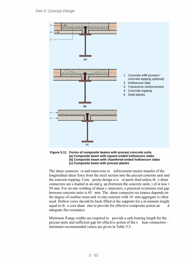
Part 2: Concept Design
2 - 51
(a)
1
2
3
(b)
(c)
4
5
1 Concrete infill (screed / concrete topping optional)
2 Hollowcore slab 3 Transverse reinforcement 4 Concrete topping 5 Solid planks
Figure 5.11 Forms of composite beams with precast concrete units
(a) Composite beam with square-ended hollowcore slabs (b) Composite beam with chamfered-ended hollowcore slabs (c) Composite beam with precast planks
The shear connecto rs and transverse re inforcement ensure transfer of the longitudinal shear force from the steel section into the precast concrete unit and the concrete topping. Com posite design is n ot perm itted unless th e shear connectors are s ituated in an end g ap (between the concrete units ) of at leas t 50 mm. For on-site welding of shear c onnectors, a practical m inimum end gap between concrete units is 65 mm. The shear connector res istance depends on the degree of confine ment and in situ concrete with 10 mm aggregate is often used. Hollow cores should be back-filled at the supports for a m inimum length equal to th e core diam eter to provide for effective composite action an d adequate fire resistance.
Minimum fl ange widths are required to provide a safe bearing length for the precast units and sufficient gap for effective action of the s hear connectors – minimum recommended values are given in Table 5.5.

Part 2: Concept Design
2 - 52
Table 5.5 Minimum widths for bearing of PC units
Minimum beam width
Internal beam 180 mm 75 mm or 100 mm deep solid precast unit
Edge beam 210 mm
Internal beam 180 mm Hollow core precast unit
Edge beam 210 mm
Non-composite edge beam 120 mm
Edge beams are often designed as non-composite, with nom inal shear connection provided to meet robustness and stability requirements. These shear connectors are usually site-welded thr ough openings cast in the precast units. Composite edge beam s require careful de tailing of U-bar reinf orcement in to slots in the precast concrete units, and a greater minimum flange width.
Temporary bracing providing lateral rest raint is often required to reduce the effective le ngth f or latera l tors ional bucklin g of the beam during the construction stage, when only one side is loaded . Full tors ional restraint in the temporary condition may be difficult to achieve, unless deep restraint members with rigid connections are used, or by developing ‘U-fram e action’ involving the beams, the restraint members and rigid connections.
5.5.2 Beam span and design criteria
Long span secondary beam s should pr ovide sufficient m inimum width to support the P.C. units as given in Table 5.5, so an IPE 400 mm is the minimum practical beam depth. Beams that are pl aced parallel to th e span of the precas t units cannot usually be designed compositely.
Edge beams are generally designed as non-composite, but are tied into the floor to meet robustness requirements.
Transverse reinforcement must be provided in all com posite design cases, as shown in Figure 5.11 and Figure 5.12.
The critical check is of ten torsional resistance and twist, or com bined torsion and lateral torsional buck ling resistance in the cons truction condition (with loads on one side only).

Part 2: Concept Design
2 - 53
Figure 5.12 Composite floor construction with precast concrete hollow core
units, showing transverse reinforcement bars placed within open cores
5.5.3 Services integration
Main service ducts are located below the beams with larger services equipment located between beam s. Allow for 1200 mm overall depth including ceiling and services. Openings can be provided in the beam web but the beam s should be designed as non-composite in this case.
5.5.4 Fire protection
Spray, board or intumescent coating may be used as the fire protection systems to beams supporting precast concrete units.
Transverse bars m ust be carefully deta iled into the pre cast units – extending 600 mm into each un it. For 90 to 120 minutes fire resistan ce, a 50 mm (minimum) concrete topping is required.
5.6 Non-composite beams with precast units 5.6.1 Description
Precast units m ay be s upported on the top fl ange of the steel beams, or supported on ‘shelf’ angles. The P.C. units are either in the form of hollow core units, norm ally 150 – 400 mm de ep, or solid planks of 75 mm to 100 mm depth. Hollow core p recast concrete un its can be us ed to span up to 15 m

Part 2: Concept Design
2 - 54
(400 mm or deeper). An exam ple of long span precast concrete units being placed on steel beams is shown in Figure 5.13.
Shelf angles are bolted or welded to the beam web, with an outstand leg long enough to provide adequate bearing of the precast unit and to allow installation of the units under the top flange of the beam s. Precast concrete u nits are generally grouted in position. The P.C. un its may have either a screed (which may be structural), or a raised floor.
Figure 5.13 Long span precast concrete units being placed on steelwork
Temporary late ral b racing is of ten requir ed to lim it the ef fective leng th f or lateral torsional buckling of the beam during the construction stage when only one side is loaded.
In order to meet robustness requirements, mesh and a structural topping may be required, or reinforcem ent concreted into hollow cores and passed through holes in the steel beam web. Tying m ay also be required between the concrete units and the edge beams.
5.6.2 Beam spans and design criteria
Construction stage loading (precast planks on one side only) must be considered. Tem porary bracing m ay be required. Beam s loaded on one sid e only in the perm anent condition should designed for the applied torsional moment.
When the top flange of a beam supports precast planks, th e minimum flange width is 180 mm to allow for m inimum bearing and a 30 mm gap between the P.C. units, as illustrated in Figure 5.14.
Shelf angles should project at least 50 mm beyond the beam flange. When shelf angles are provided, 2 5 mm clearance is req uired between the end of the concrete unit and the beam flange, as shown in Figure 5.15.

Part 2: Concept Design
2 - 55
The critical beam check is often torsional resis tance, or co mbined torsion and lateral torsional buckling resistance in the construction condition (with loads on one side only).
5.6.3 Services integration
Main service ducts are located below the beams with larger services equipment located between beams.
180 min.
30
75 min.
50
50 min.
75 min.
(a) Units sitting on downstand beam (b) Units sitting on shelf angle beam Figure 5.14 Floor construction with precast concrete units in non-composite
construction
25 min.
Figure 5.15 Bearing and clearance requirements for precast units on shelf
angle beams
5.6.4 Fire protection
Fire protection m ay be spray, board or an in tumescent coa ting to the beam . Shelf angle beam s can achieve 30 minutes fire resistance by up-turning the angles, (the vertical leg is above the projecting leg, as shown in Figure 5.15) so that they remain relatively cool in fire.
5.7 Integrated beams with precast concrete units 5.7.1 Description
Precast concrete units m ay be used as part of a slim floor or integ rated beam system, in which the b eams are contained within the floor depth, as illustrated in Figure 5.16. Two forms of steel beams are commonly used:

Part 2: Concept Design
2 - 56
A steel plate (typically 15 mm thick) m ay welded to the underside of an H section. This plate extends beyond the bottom flange by at least 100 mm either side, in order to support the precast concrete units.
A 20 mm fl ange plate (typical) m ay be we lded to half of an I section cut along the web.
A structural concrete topping with rein forcement is recommended in order to tie the P.C. units together. The topping thickness should cover the P.C. units by at least 50 mm. I f used without a t opping, reinforcement s hould be provided through the web of the beam to tie the fl oor on each sid e of the beam together in order to meet robustness requirements.
1 Hollowcore concrete slab
2 IFB/SFB – beam 3 Column section
Figure 5.16 Integrated floor beam (slim floor beam) and precast concrete units
A com posite integ rated beam can be achieved by welding shear conn ectors (normally 19 mm diameter 70 mm long) to the top flange of the steel section. Reinforcement is then placed across the flange into slots prepared in the precast units, or on top of shallow precast units. If the beams are designed compositely, the topping should cover the shear c onnectors by at least 15 mm, and the precast units by at least 60 mm.
A typical structural arrangem ent in wh ich the integrated beam s span 6 m and the P.C. units span 7,5 m is illustrated in F igure 5.17. In this cas e, th e P.C. units are 200 mm deep and a 60 mm concrete topping is used. The edge beam s are IPE, designed as n on-composite and are placed belo w the P.C. units. Nominal shear connectors are provided to m eet robustness requirem ents. In this case, th e slab can be cas t level w ith th e top of the beam, as shown in Figure 5.18.
5.7.2 Beam spans and design criteria
Ideally, th e span of the precast con crete units and the b eam span should be optimised to produce a f loor thickness compatible with the beam depth. Beams loaded on one side only are relatively h eavy because of their torsional loading. Also, tors ional effects during construction will need to be checked. A central spine beam with precast units spanni ng to downstand edge beam s (beams located under the P.C. units, but co ncealed in the wall) will generally b e more economic than the P.C. units spanning along the building, onto a series of transverse spanning beams.

Part 2: Concept Design
2 - 57
Composite edge beam s require careful detailin g of U-bars around th e shear connectors and into the precast units or structural topping – therefore non-composite edge beams are preferred.
Critical checks are usu ally the torsi onal res istance, com bined to rsion an d lateral torsional buckling resistance in the construction condition (when loaded on one side only), or lateral torsiona l buckling in the construction condition (with loads on both sides). Deflection may be critical for all types of integrated beams.
Typical beam sizes of s lim floor beams and integrated beams for spans of 5 m to 8 m are presented in Table 5.6 and Table 5.7 respectively.
6.0m
3.0m 3.0m
6.0m
6.0m
7.5m
HEA 220 S
355
HEA 220 S
355
HEA 240 S
355
HEA 220 S
355
HEA 240 S
355
HEA 220 S
355
HEB 220 S
355
HEA 240 S
355
HEA 240 S
355
HEA 220 S
355
HEB 220 S
355
HEA 240 S
355
HEA 240 S
355
HEA 220 S
355
HEA 220 S
355
HEA 220 S
355
HEA 240 S
355
HEA 220 S
355
IPE 400 S235
IPE
A 4
50 S
235
IPE
400
S23
5
IPE
400
S23
5
IPE
240
S23
5IP
E 2
40 S
235
IPE
240
S23
5
IPE
O 3
00 S
235
IPE 400 S235
IPE A 400 S235
6HEB 260/460 x 15
IPE A 400 S235
6HEB 260/460 x 15
IPE 220 S235
IPE 220 S235
1
2
1
345
1. Side bracing 2. Precast concrete units + 60 mm NWC topping 3. Wall bracing 4. Stairs 5. Lifts and toilets 6. Slimflor beam Figure 5.17 Slim floor steelwork arrangement for a four-storey rectangular
building (central spine slim floor beam and downstand edge beams)

Part 2: Concept Design
2 - 58
5.7.3 Services integration
The flat floor soffit allo ws unrestricted access for services below the floor, as shown in Figure 5.18.
1
3
2
60
200
5
4
1 NWC topping 2 A142 mesh
3 T12 1200 long tie bars @ 600 ctrs through holes in web
4 HEB 260
5 460 15 plate
Figure 5.18 Slim floor construction – typical cross-section using precast units
5.7.4 Fire protection
The concrete encasement around the beam is normally sufficient to provide up to 60 minutes fire resistance without additional protection.
For 90 minutes fire res istance, an in tumescent coating or board protection to the flange plate is required. Correct deta iling o f transverse reinforcement is required, particularly for hollow core un its, where filling of the co res adjacent to the beam is necessary.
Table 5.6 Span of slim floor beams comprising HE sections and welded bottom plate
Typical beam size for slim floor beam span Span of slab (m)
5 m 6 m 7 m 8 m
5 HE 200A HE 240A HE 280A HE 300A
6 HE 240A HE 280A HE 300A HE 280A
7 HE 280A HE 300A HE 280B HE 300B
8 HE 280A HE 280B HE 300B HE 320B
Slab depth equal to the beam depth, plus 50 mm The welded plate should be 150 mm wider than the HE section
Table 5.7 Span of integrated beams cut from IPE sections with a welded bottom flange plate
Typical beam size for integrated beam span Span of slab (m)
5 m 6 m 7 m 8 m
5 IPE 400 IPE 500 IPE 550 IPE 600
6 IPE 500 IPE 550 IPE 600 HE 500A
7 IPE 550 IPE 600 HE 500A HE 600A
8 IPE 600 HE 500A HE 600A HE 600B
All section sizes are cut to be half the IPE section sizes given A 20 mm thick welded bottom flange plate is used in all cases

Part 2: Concept Design
2 - 59
5.8 Asymmetric beams and deep decking 5.8.1 Description
Asymmetric beams (ASBs) may be used to support composite slabs using deep decking. ASBs are hot rolled steel beam s with a wider bottom flange than top. The section m ay have e mbossments rolled into the top flange and acts compositely with the concrete encasement without the need for additional shear connectors. The decking spans between the bottom flanges of the bea ms and supports the loads during construction.
Span arrangements are normally based on a 6 m to 9 m grid, with a slab depth of 280-350 mm. Decking requires propping during the construction stage for spans of more than 6 m. Reinforcing bars (16 – 25 mm diameter) placed in the ribs of the slab give sufficient fire resistance.
ASB sections are generally approxim ately 300 mm deep. The sections m ay be rolled with rela tively thick webs (e qual to or thicker than the f langes), which offer a fire resis tance of 60 minutes without additional protection (for norm al office loading).
Services can be integrated by for ming elongated openings in the webs of the beams, and by locating ducts between the rib s of the decking, as illus trated in Figure 5.19.
Edge beams can be slim floor beams ut ilising a rectangular hollow section, or downstand beams. Ties, normally Tees with the leg cast in th e slab, are used to restrain th e colum ns interna lly in the direction at right angles to the m ain beams.
Mesh reinforcem ent (A142 for 60 minutes fire resistance and A193 for 90 minutes) is placed in the slab ov er the ASB. If the top flange of the ASB is level with the surface of the concrete, the slabs e ach side of the ASB should be tied together to m eet robustness re quirements, norm ally by reinforcem ent (typically T12 bars @ 600 centres) passed through the web of the ASB. ASBs are norm ally designed as non-composite if the concrete cover over the top flange is less than 30 mm.
Figure 5.19 Integration of services using asymmetric beams

Part 2: Concept Design
2 - 60
5.8.2 Beam spans and design criteria
In this form of construction with d eep decking, the m aximum span of the decking is lim ited to approxim ately 6 m for a 300 mm dee p slab, in order to avoid tem porary propping. The maxim um spa n of the ASB beams is in the range of 6 m to 10 m, depending on their size and spacing.
5.8.3 Services integration
Unrestricted distribution of services below the floor is provided. Small services and ducts (up to 160 mm diameter) can be passed through holes in the beam webs and between ribs in the decking, as shown in Figure 5.20. The following floor zones m ay be used in schem e design using asymm etric beams and deep decking.
600 – 800 mm with light services (and a raised floor)
800 – 1000 mm with air conditioning (and a raised floor)
150
300
50
800mm
200
5050
1
2
3
4
1 Raised floor 2 Ducting through beam 3 Slimline fan coil unit 4 Lighting and Ceiling
Figure 5.20 Typical floor construction using asymmetric beams and deep
decking
5.8.4 Fire protection
Fire engineered ASBs have relatively thick webs and with the web a nd top flange encased with concrete require no additional fire protection for up to 60 minutes.
Other ASB sections require fire prot ection for greater than 30 minutes – normally by board to the bottom flange.
5.9 Beam connections All the f loor system s reviewed in this section utilise s imple connection s (nominal pins), which are not assum ed to develop significant m oments. To realise this assum ption in practice, the connection deta ils must be ductile, in order to accommodate the rotation that develops at the connection.
Full depth connections, where the end plat e is welded to the web and flanges, are provided for floor m embers that are s ubject to tors ion, such as integrated beams or slim floor beam s. For any floor solution, the possib ility of torsional loading in the construction stage should be checked, as connections with torsional resistance, or temporary restraints may be required.

Part 2: Concept Design
2 - 61
The use of full depth end plates m ay mean that the connections can no longer be assumed to be pinned. In m any instances, it is assum ed that the connection may still b e regarded as pinned, as long as the end plate thickness is no more than half th e bolt d iameter, in S27 5 stee l. Som e regulatory autho rities m ay wish to see a calculation to demonstrate the connection classification.
5.9.1 Beam to column connections
When connections are not subject to to rsion, sim ple (vertical shear only) connections are usually detailed. Sta ndard connections are used, with the choice of detail left to the steelwork contractor. The standard connections are the flexible end plate, a fin plate or double angle cleats, shown in Figure 5.21. It is commonly assumed that the types of connections shown in Figure 5.21 are pinned, as long as the plates and angles are relatively thin (10 mm in S275 steel). Multi-storey steel buildings Part 5: Joint design[8] cover the design of pinned connections.
(a) (b) (c) Figure 5.21 Standard beam connections. (a) Flexible end plate (b) Fin plate
(c) Double angle cleat
In general, flexible end plates ar e generally used for beam -to-column connections. Fin plates are often used for beam-to-beam connections.
5.9.2 Beam to beam connections
Beam-to-beam connections also utilis e the standard details, although the secondary beam will need to be notched, as shown in Figure 5.22.
Figure 5.22 Beam to beam connection
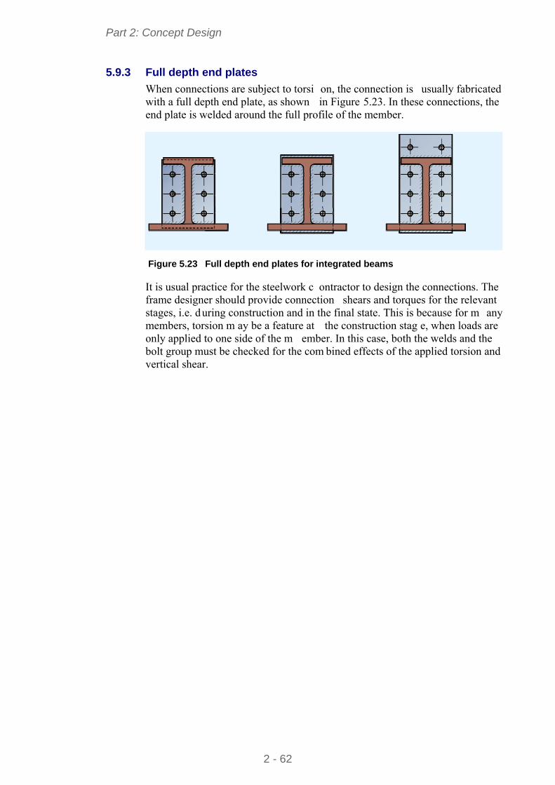
Part 2: Concept Design
2 - 62
5.9.3 Full depth end plates
When connections are subject to torsi on, the connection is usually fabricated with a full depth end plate, as shown in Figure 5.23. In these connections, the end plate is welded around the full profile of the member.
Figure 5.23 Full depth end plates for integrated beams
It is usual practice for the steelwork c ontractor to design the connections. The frame designer should provide connection shears and torques for the relevant stages, i.e. during construction and in the final state. This is because for m any members, torsion m ay be a feature at the construction stag e, when loads are only applied to one side of the m ember. In this case, both the welds and the bolt group must be checked for the com bined effects of the applied torsion and vertical shear.

Part 2: Concept Design
2 - 63
6 OTHER DESIGN ISSUES
The following design issues will affect the overall building concept, including the structural design aspects.
6.1 Accidental Actions EN 1990 requires that structures be de signed for accidental design situations. The situations that need to be consider ed are set out in EN 1991-1-7, and these relate to both identified acciden tal actions and u nidentified accidental actions. The strategy to be adopted in either case depends on three “consequence classes” that are set out in EN 1990; for buildings, one of those classes has been subdiv ided and th e catego ries of building in each class are set o ut in EN 1991-1-7, Table A.1.
For identified accid ental actions, desi gn strategies in clude protectin g th e structure against the action but more generally, and for unidentified actions, the structure should be designed to have an appropriate level of “robustness”, defined as:
“The ability of a structure to withstand events like fire, explosions, impact or the consequences of human error, without being damaged to an extent disproportionate to the original cause.”
For unidentified actions, the strategy fo r achieving robustness is set out in EN 1991-1-7 § 3.3, which says that:
“… the potential failure of the structure arising from an unspecified cause shall be mitigated … by adopting one or more of the following approaches:
a) designing key elements on which the stability of the structure depends, to sustain the effects of a model of accidental action Ad;
b) designing the structure so that in the event of a localised failure (e.g. failure of a single member) the stability of the whole structure or of a significant part of it would not be endangered;
c) applying prescriptive design/detailing rules that provide acceptable robustness for the structure (e.g. three dimensional tying for additional integrity, or a minimum level of ductility of structural members subject to impact).”
6.1.1 Consequence classes
EN 1990 defines three consequences classes:
CC1 Low consequences of failure
CC2 Medium consequences of failure
CC3 High consequences of failure

Part 2: Concept Design
2 - 64
Class CC2 is subdivided by EN 1991-1-7 into CC2a (Lower risk group) and CC2b (Upper risk group). Medium rise buildings mostly fall with group CC2b. Examples of categories given by Tabl e A.1 of EN 1991-1-7 include the following: Table 6.1 Examples of building categorisation (taken from Table A.1 of
EN 1991-1-7)
Consequence Class
Example of categorization of building type and occupancy
2B Upper Risk Group
Hotels, flats, apartments and other residential buildings greater than 4 storeys but not exceeding 15 storeys. Educational buildings greater than single storey but not exceeding 15 storeys. Retailing premises greater than 3 storeys but not exceeding 15 storeys. Offices greater than 4 storeys but not exceeding 15 storeys. All buildings to which the public are admitted and which contain floor areas exceeding 2000 m2 but not exceeding 5000 m2 at each storey.
The recomm ended strategy for Conse quence Class 2b involves either the design for localised failure (see Section 6.1.2) or the design of colum ns as key elements (see Section 6.1.6).
6.1.2 Design for the consequences of localised failure in multi-storey buildings
In multi-storey build ings, the requ irement for r obustness generally leads to a design strategy where the colum ns are tied in to the rest of the s tructure. This should m ean that any one length of column cannot easily be removed. However, should a len gth be removed by an acciden tal action, th e floor systems should be able to develop catenary action, to lim it the extent of the failure.
It should be noted that the requ irements are not intended to ensur e th at th e structure is still serv iceable following some extreme event, but that da mage is limited, and that progressive collapse is prevented.
6.1.3 Horizontal tying
EN 1991-1-7, A.5 provides guidance on the horizontal tying of fra med structures. It gives expressions for th e design tensile resistance requ ired for internal and perimeter ties. The calculated tying force is generally equal to the vertical shear.
Tying forces do not necessarily need to be carried by the steelwork fram e. A composite concrete floor, for example, can be used to tie columns together, but must be designed to perfor m this fu nction. Addition al reinforcem ent may be required, and the columns (particularl y edge colum ns) m ay need careful detailing to ensure the tying force is transferred between column and slab.
If the tying forces are to be carried by the structural steelwork alone, it should be noted th at the check for tying resis tance is entirely s eparate to that f or resistance to vertical forces. The shear force and tying forces are never applied

Part 2: Concept Design
2 - 65
at the sam e tim e. Furtherm ore, the usual requirem ent that m embers and connections rem ain serviceable unde r design loading is ignored when calculating resistance to tying, as ‘s ubstantial perm anent deform ation of members and their co nnections is acceptable’. Guidance on the des ign of connections to resist tying forces is given in Multi-storey steel buildings. Part 5: Joint design[8].
6.1.4 Tying of precast concrete floor units
EN 1991-1-7, §A.5.1 (2) requires that when concrete or other heavy floor units are used (as floors), they should be tie d in the direction of their span. The intention is to prevent floor units or floor slabs s imply falling through the steel frame, if the steelwork is m oved or removed due to som e major trauma. Slabs must be tied to each other over supports , and tied to edge beam s. Tying forces may be determined from §9.10.2 of BS EN 1992-1-1.
6.1.5 Vertical tying
EN 1991-1-7, A.6 provides guidance on the ve rtical tying of framed structures. The clause recommends that co lumn splices should be capable of carrying an axial tens ion equal to the larg est design vertical permanent and va riable load reaction applied to the c olumn from any one storey. In practice, th is is n ot an onerous obligation, and m ost splices de signed for adequate stiffness and robustness during erection are likely to be sufficient to carry the axial tying force. Guidance on th e design of splices to resist tying forces is given in other publications in this series Multi-storey steel buildings. Part 5: Joint design [8].
6.1.6 Key elements
EN 1991-1-7, A.8 provides guidance on the design of “Key elem ents”. It recommends that a key elem ent should be capable of sustaining an accidental design action of Ad applied in h orizontal an d vertical directions (in one direction at a tim e) to the m ember and any attached com ponents. The recommended value of Ad for building structures is 34 kN/m2. Any other structural component that pr ovides “lateral restraint vi tal to the stability” of a key element should also be designed as a key element.
6.1.7 Risk assessment
Buildings which fall in to consequence cl ass 3 have to be assessed using risk assessment techniques. Annex B of EN 1991-1-7 provides infor mation on risk assessment and B.9 provides guidance specific to buildings.
6.2 Floor dynamics Floor response is assessed first by calculating the fundamental frequency of the floor, and checking this against a limit. Limits are given in National regulations or technical guidance, and m ay vary between countries. Generally, if the fundamental frequency of th e floor structure is greater than 4 Hz, the floor is usually considered to be satisfactory. The natural frequency of the floor is then at least twice the natu ral frequ ency due to r apid walk ing. W hilst this is generally acceptable for busy workplaces, it is not appropriate for quieter areas of buildings where vibrations are more perceptible.

Part 2: Concept Design
2 - 66
A more appropriate approach is an assessment based on a ‘response factor’ that takes into account the amplitude of th e vibration, which is norm ally measured in terms of acceleration. Allowable res ponse factors are also given in national regulations or technical guidance a nd m ay vary between countries. Higher response factors indicate increasingly dynamic floors that are m ore noticeable to the occupants. A response factor of 8 relative to a ba se acceleration of 5 mm/s2 is generally taken to indicate acceptable performance for an office, but it may be necessary to reduce the response factor to (for example) 1 to 2 for a hospital or other specialist rooms.
In practice, response factors are reduced (i.e. vibration is less noticeable) by increasing the mass participating in the motion. Long-span beams are generally less of a dynam ic problem than shorter sp ans, which is contrary to ideas based on natural frequency alone.
Beam layout is often important, as longe r continuous lines of secondary beam s in composite construction result in lower response factors than shorter lengths, because m ore m ass participates in the motion with long er lin es of b eams. Figure 6.1 shows two possible arrangem ents of beams. The response factor for arrangement (b) will be lower (less noticeable to occupants) than arrangem ent (a), as the participating mass is increased in arrangement (b).
The dynamic response of bare floors duri ng construction is m ore likely to be perceived than the same floor when furnished and occupied.
Further information on the hum an induced vibration if steel structures can be obtained from the HIVOSS website[9].
Primary beams
Secondarybeams
Secondarybeams
Primary beams
(a) (b) Figure 6.1 Alternative beam layouts

Part 2: Concept Design
2 - 67
6.3 Corrosion protection The corros ion of steel is an electroch emical process that requ ires the simultaneous presence of water and oxygen. In the absence of either, corrosion does not occur. Hence, f or unprotected st eel in dry environments (e.g. internal steelwork), corrosion will be m inimal. The principal factors that determine the rate of corrosion of steel in air are the proportion of total time during which the surface is wet, due to rainfall, cond ensation etc, and the ty pe and am ount of atmospheric pollution (e.g. sulphates, chlorides, etc.).
External steelwork will need corrosi on protection. The local environm ent is important, and can be b roadly classified accord ing to EN ISO 12944-2, which describes categories from C1 (heated in teriors) through to C5 (aggressive marine or industrial environm ent). Many corrosion protection system s are available, including metallic coatings (such as galvanising) and paint system s, and should be chosen based on the environment classification.
Occasionally, local regulations demand that even interior steelwork or encased members must have corrosion protecti on, but in general, hidden steelwork inside dry, heated buildings requires no protection at all.
6.4 Temperature effects In theory, steel frames expand and contract with changes in temperature. Often, the temperature change of the steelwork itself is m uch lower than any change in the external temperature, because it is protected.
It is recommended that expansion joints are avoided if possible, since these are expensive a nd can be d ifficult to d etail cor rectly to m aintain a weathe r-tight external envelope. In preference to pr oviding expansion joints, the fram e may be analysed including the design e ffects of a tem perature change. The temperature actions m ay be determ ined from EN 1991-1-5, and com binations of actions verified in ac cordance with EN 1990. In most cases, the m embers will be found to be adequate.
Common practice for multi-storey buildings in Northern Europe, in the absence of calculations, is tha t expansion joints do not need to be provided unless the length of th e building exceeds 100 m for simple (braced) frames, and 50m in continuous construction. In war mer climates, common practice is to lim it the length to around 80 m. These recomm endations apply to the steel fram e – expansion joints should be provided in stiff external cladding such as brickwork. When expansion joints in multi-storey buildings are provided, they are commonly arranged to coincide with significant changes of shape on plan, or at sign ificant changes in floor level, or to separa te parts of the structure on different foundations.
6.5 Fire safety Building designers should consider the im plications of fire resistance when choosing the structural configuration and should address issues such as:
Means of escape.

Part 2: Concept Design
2 - 68
Size of compartment
Access and facilities for the Fire Service
Limiting the spread of fire
Smoke control and evacuation
Adoption of sprinklers.
Generally, the above issues are addressed by the scheme architect.
In addition to the above, structural performance in the event of a fire must meet prescribed s tandards, expressed as a peri od of fi re resistance of the structural components. As an alternative, a ‘fire engineering’ approach may be followed which acco unts for th e fire s afety of the wh ole building , considerin g the structure use, the hazards, the risks and how these are addressed.
In general, the structural engineer and architect should consider:
Schemes which have fewer beams to fire protect
The opportunity to use unprotected steelwork
The influence of service integ ration on the fire protection system , a nd appropriate solutions such as intumescent coatings on cellular beams
The influence that site applied prot ection m ay have on the construction programme, particularly if the protection is a spray
Requirements for the final appearance of exposed steelwork when choosing a fire protection system.
Guidance on the fire engineering of multi-storey steel structures is given in Multi-storey steel buildings. Part 6: Fire engineering[10].
6.6 Acoustic performance Limits on r esidual noise, after accounting for attenuation by the building façade, are usually specified in National regulations for open plan offices and conference rooms. Criteria are also usually given for the acceptable noise from building services in the same categories.
Maximum and minimum ambient noise leve l targets are generally defined for spaces within buildings. These are appropriate for comfort in both com mercial premises and residential accommodation.
To meet acoustic p erformance standards, the construction de tails may require special attention. In Figure 6.2 precast concrete units have an isolated screed (a screed separated from the precas t unit by a prop rietary resilient laye r, or by a waterproof membrane and dense m ineral wool). In addition, the ceiling is no t in direct contact with the steel beam, and is at least 8 kg/m2. Particular attention must also be paid to th e junction where walls m eet floors and cei lings (known as “flanking” details). An exa mple of a typical flanking detail is shown in Figure 6.3, where there is dense m ineral wool around the st eel beam, sealant

Part 2: Concept Design
2 - 69
where the wall finish m eets the ceiling, and sealant where the floor treatm ent meets the wall finish.
Figure 6.2 Typical floor treatment to provide improved acoustic performance
1
2
5
3
4
6
1 Dense mineral wool 2 Acoustic sealant 3 Mineral wool packing 4 Precast concrete unit 5 Floor treatment 6 Sealant Figure 6.3 Typical flanking detail for an internal separating wall
Separating walls between occupancies are likely to be of double skin construction to reduce noise transmission, facilitating the use of bracing within the wall construction.
Part 2: Concept Design
2 - 70
6.7 Energy efficiency Thermal insulation pro vided in th e building envelope is traditiona lly the architect’s responsibility. However, the st ructural engineer must be involved in the developm ent of appropriate deta ils and layout. Supporting system s for cladding may be m ore com plicated in order to m eet therm al perform ance requirements, involving eccentric connection to the supporting steelwork. Steel members that penetrate the insulation, such as balcony supports, need special consideration and detailing to avoid ‘t hermal bridging’. Therm al bridges not only lead to heat loss, b ut may also lead to con densation on the inside of the building.
6.8 Cladding Cladding sy stems that m ay be used in m ulti-storey bu ilding depend on the building height and the degree of fenest ration. Fully glazed facades are widely used, although provision for solar shading generally has to be m ade. An example of a fully glazed cladding is shown in F igure 6.4. The following cladding systems are generally:
Brickwork Ground supported up to 3 storeys. Supported by stainless steel angles attached to edge beams for taller buildings
Glazing systems Generally triple glazing or double layer facades supported on aluminium posts or glass fins
Curtain walling Aluminium or other lightweight façade that is attached to the perimeter steelwork
Insulated render or tiles Cladding system supported on light steel infill walls, mainly used in public sector buildings and residential buildings.

Part 2: Concept Design
2 - 71
Figure 6.4 Triple glazed wall in a multi-storey commercial building
6.8.1 Brickwork cladding
Brickwork cladding is generally supported from the structural fram e by continuous angles, bracket angles or i ndividual brackets, often for med from stainless steel to avoid any unsightly staining. Generally, the brackets will have some provision of vertical adjustment, often using two matc hing plates with serrations o n the m ating surfaces. Figure 6.5 shows typical fixings to steel beams, where the bracket arrangem ent is connected to a plate welded between the flanges of the beam.
Figure 6.5 Typical fixing details to steel members
Figure 6.6 shows typical fixing details to the edge of conc rete slabs. The bracket m ay fix to the sop of the sla b, or m ay connect to a dovetail shaped profile formed in the edge trim of the slab.

Part 2: Concept Design
2 - 72
Figure 6.6 Typical fixing details to concrete slabs
6.8.2 Glazing systems
Many steel structures have glazed facades. T here a re a large num ber of different system s, and the m anufacturer of the system should be consulted when specifying the system , and particular ly the fixings to the steel fram e. In many cases the f ixings will be at th e corners of glazed pan els, and the panels themselves will have some form of gasket on the joints between panels.
A number of i mportant issues need to be addressed, notably the need to m ake provision for adjustment in the connections, because the tolerances on the steel frame and the glazing panels are generall y different. Movement due to thermal effects m ay be s ignificant, and this will have to be acco mmodated in th e support system.
6.8.3 Curtain walling
Curtain walling includes:
Metal panels (generally steel or aluminium)
Precast concrete panels
Stone cladding.
Curtain walling may be able to support their own weight and the applied loads without add itional s tructural system s. This type of panel is generally hung, (supported at the top of the panel) or supported at their base from the floor. Generally, each panel s ystem will have a proprie tary fixing detail th at allows for m ovement and adjustm ent in three directions, in orde r to ov ercome the difference in tolerances of the fra me and cladding panels. The connections can be substantial, and provision m ay be require to conceal the connections in a raised floor or ceiling zone. The slab design m ay need review in order to accommodate the local connection forces. It is also comm on that fixing s will be required to the outside edge of a floor, which is usually achieved by a dovetail channel cast into the edge of the slab.
Cladding may require a dditional s tructural support – gen erally in the form of mullions which m ay extend vertically ove r a number of floor s, possibly with intermediate horizonta l m embers (tran soms). Vertical or horizontal m etal sheeting is often supported in this way. The connections need careful consideration, to allow f or adjustm ent in three dir ections, and to allow f or movement whilst carrying lateral loads to the floors.

Part 2: Concept Design
2 - 73
6.8.4 Insulated render cladding and tiles
Insulated render cladding is a lightwe ight, energy efficient cladd ing for multi-storey stru ctures, which utilis es insu lation and render supported by a secondary steel fram e, as shown in Fi gure 6.7. With appropriate detailing and installation, this typ e of façade can be a fast, robust an d highly in sulated solution. Tiles m ay be used as a s ubstitute f or the r ender, and thes e m ay be individual tiles or pre-form ed panels. Similarly, brickwork ca n be used as the external skin, as shown in Figure 6.8.
7
6
5
2
3
1
4
1 Fire resistant plasterboard 2 Supplementary insulation 3 Steel frame 4 Sheathing board 5 Breather membrane 6 Rigid board insulation 7 Polymer modified render
Figure 6.7 Typical insulated render cladding supported by light steel framing

Part 2: Concept Design
2 - 74
3
1
2
1 Insulated board with foil face 2 Wall ties attached to dovetail
channels 3 Brickwork
Figure 6.8 Insulated infill panel with brickwork cladding

Part 2: Concept Design
2 - 75
REFERENCES
1 HICKS, S. J., LAWSON, R. M., RACKHAM, J. W. and FORDHAM, P.
Comparative structure cost of modern commercial buildings (second edition) The Steel Construction Institute, 2004
2 Steel Buildings in Europe Multi-storey steel buildings. Part 3: Actions
3 SANSOM, M & MEIJER, J Life-cycle assessment (LCA) for steel construction European commission, 2002
4 Several assessment methods are used. For example: BREEAM in the UK HQE in France DNGB in Germany BREEAM-NL, Greencalc+ and BPR Gebouw in the Netherlands Valideo in Belgium Casa Clima in Trento Alto Adige, Italy (each region has its own approach) LEED, used in various countries
5 GORG OLEWSKI, M. The role of steel in environmentally responsible buildings The Steel Construction Institute, 1999
6 Steel Buildings in Europe Multi-storey steel building. Part 4: Detailed design
7 SIMMS, W.I. RT 983: Interim guidance on the use of intumescent coatings for the fire protection of beams The Steel Construction Institute, 2004
8 Steel Buildings in Europe Multi-storey steel buildings. Part 5: Joint design
9 http://www.stb.rwth-aachen.de/projekte/2007/HIVOSS/download.php
10 Steel Buildings in Europe Multi-storey steel buildings. Part 6: Fire engineering